US10893855B2 - Retractor system and retractor with detachable handle - Google Patents
Retractor system and retractor with detachable handleDownload PDFInfo
- Publication number
- US10893855B2 US10893855B2US15/918,530US201815918530AUS10893855B2US 10893855 B2US10893855 B2US 10893855B2US 201815918530 AUS201815918530 AUS 201815918530AUS 10893855 B2US10893855 B2US 10893855B2
- Authority
- US
- United States
- Prior art keywords
- rod
- attachment portion
- retractor
- cavity
- retaining member
- Prior art date
- Legal status (The legal status is an assumption and is not a legal conclusion. Google has not performed a legal analysis and makes no representation as to the accuracy of the status listed.)
- Active, expires
Links
- 238000003780insertionMethods0.000claimsdescription2
- 230000037431insertionEffects0.000claimsdescription2
- NJPPVKZQTLUDBO-UHFFFAOYSA-NnovaluronChemical compoundC1=C(Cl)C(OC(F)(F)C(OC(F)(F)F)F)=CC=C1NC(=O)NC(=O)C1=C(F)C=CC=C1FNJPPVKZQTLUDBO-UHFFFAOYSA-N0.000description10
- 210000003484anatomyAnatomy0.000description7
- 238000000034methodMethods0.000description4
- 238000001356surgical procedureMethods0.000description3
- 238000013459approachMethods0.000description2
- 210000000988bone and boneAnatomy0.000description2
- 230000006378damageEffects0.000description2
- 208000014674injuryDiseases0.000description2
- 210000004872soft tissueAnatomy0.000description2
- 210000003813thumbAnatomy0.000description2
- 210000001519tissueAnatomy0.000description2
- 210000001835visceraAnatomy0.000description2
- 208000027418Wounds and injuryDiseases0.000description1
- 230000015572biosynthetic processEffects0.000description1
- 230000000881depressing effectEffects0.000description1
- 230000003993interactionEffects0.000description1
- 230000014759maintenance of locationEffects0.000description1
- 238000012986modificationMethods0.000description1
- 230000004048modificationEffects0.000description1
- 239000004065semiconductorSubstances0.000description1
- 229910001220stainless steelInorganic materials0.000description1
- 239000010935stainless steelSubstances0.000description1
- 230000008733traumaEffects0.000description1
Images


Classifications
- A—HUMAN NECESSITIES
- A61—MEDICAL OR VETERINARY SCIENCE; HYGIENE
- A61B—DIAGNOSIS; SURGERY; IDENTIFICATION
- A61B17/00—Surgical instruments, devices or methods
- A61B17/02—Surgical instruments, devices or methods for holding wounds open, e.g. retractors; Tractors
- A61B17/0218—Surgical instruments, devices or methods for holding wounds open, e.g. retractors; Tractors for minimally invasive surgery
- A—HUMAN NECESSITIES
- A61—MEDICAL OR VETERINARY SCIENCE; HYGIENE
- A61B—DIAGNOSIS; SURGERY; IDENTIFICATION
- A61B17/00—Surgical instruments, devices or methods
- A61B17/02—Surgical instruments, devices or methods for holding wounds open, e.g. retractors; Tractors
- A61B17/0206—Surgical instruments, devices or methods for holding wounds open, e.g. retractors; Tractors with antagonistic arms as supports for retractor elements
- A—HUMAN NECESSITIES
- A61—MEDICAL OR VETERINARY SCIENCE; HYGIENE
- A61B—DIAGNOSIS; SURGERY; IDENTIFICATION
- A61B17/00—Surgical instruments, devices or methods
- A61B2017/00367—Details of actuation of instruments, e.g. relations between pushing buttons, or the like, and activation of the tool, working tip, or the like
- A—HUMAN NECESSITIES
- A61—MEDICAL OR VETERINARY SCIENCE; HYGIENE
- A61B—DIAGNOSIS; SURGERY; IDENTIFICATION
- A61B17/00—Surgical instruments, devices or methods
- A61B2017/0046—Surgical instruments, devices or methods with a releasable handle; with handle and operating part separable
- A—HUMAN NECESSITIES
- A61—MEDICAL OR VETERINARY SCIENCE; HYGIENE
- A61B—DIAGNOSIS; SURGERY; IDENTIFICATION
- A61B17/00—Surgical instruments, devices or methods
- A61B2017/00477—Coupling
Definitions
- the present disclosurerelates to a surgical apparatus that retracts soft tissue and other anatomy of a patient in order to provide access to an operative site.
- a surgeonmay make an incision in a patient to access internal organs, bones, and/or other anatomical structures.
- Retraction devicesmay be used to hold back soft tissue and other patient anatomy in the immediate area of the incision.
- Such retraction devicesmay provide the surgeon with an unobstructed view of the internal organs, bones, and/or other anatomical structures.
- the retraction devicesmay provide the surgeon with an opening via which the surgeon may access the anatomical structures with one or more surgical tools.
- aspects of this disclosureprovide a retractor system comprising retractors that retract anatomy to provide exposure of an operative site.
- various aspects of this disclosureare directed to a retractor having a handle that may be used to manipulate and position a retractor blade. After positioning the retractor blade, the handle may be detached and removed in order to provide less encumbered access to the operative site.
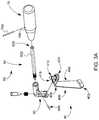
- FIG. 1provides a perspective view of a retractor system in accordance with various aspects of the present disclosure.
- FIG. 2provides a perspective view of a retractor assembly of FIG. 1 in accordance with various aspects of the present disclosure.
- FIG. 3Aprovides an exploded view of a handle assembly in regard to a retractor blade of FIG. 2 .
- FIG. 3Bprovides a detailed, perspective view a base portion 420 of the retractor blade of FIG. 2 .
- FIG. 4provides a perspective view of an attachment portion of the handle assembly of FIG. 3A .
- FIG. 5provides a cross-sectional view of a retractor blade of FIG. 2 with a locked handle assembly as the retractor blade is being attached to a jointed arm of the retractor assembly.
- FIG. 6provides cross-sectional view of the retractor blade of FIG. 2 with the handle assembly in an unlocked position.
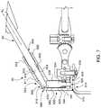
- FIG. 7provides cross-sectional view of the retractor blade of FIG. 2 with the handle assembly in an locked position.
- “and/or”means any one or more of the items in the list joined by “and/or”.
- “x and/or y”means any element of the three-element set ⁇ (x), (y), (x, y) ⁇ . In other words, “x and/or y” means “one or both of x and y.”
- “x, y, and/or z”means any element of the seven-element set ⁇ (x), (y), (z), (x, y), (x, z), (y, z), (x, y, z) ⁇ . In other words, “x, y and/or z” means “one or more of x, y, and z.”
- first, second, etc.may be used herein to describe various elements, these elements should not be limited by these terms. These terms are only used to distinguish one element from another element. Thus, for example, a first element, a first component or a first section discussed below could be termed a second element, a second component or a second section without departing from the teachings of the present disclosure. Similarly, various spatial terms, such as “upper,” “lower,” “side,” and the like, may be used in distinguishing one element from another element in a relative manner.
- componentsmay be oriented in different manners, for example a semiconductor device may be turned sideways so that its “top” surface is facing horizontally and its “side” surface is facing vertically, without departing from the teachings of the present disclosure.
- the term “on”will be utilized in the document to mean both “on” and “directly on” (e.g., with no intervening layer).
- FIG. 1illustrates an embodiment of a retractor system 10 in accordance with various aspects of the present disclosure.
- the retractor system 10may include a frame assembly 20 , a jointed arm 30 , and a plurality of retractor blades 40 .
- the various components of the retractor system 10may be made, for example, of stainless steel.
- the frame assembly 20may include one or more posts 22 , frame arms 24 , and clamps 26 .
- Each post 22may be fixed to a rail and/or a hospital bed (not shown) such that the post 22 extends upward in a generally vertical direction.
- Each post 22may provide a location to which a frame arm 24 may be secured.
- two posts 22are secured on opposite sides of a hospital bed, with a frame arm 24 secured to each post 22 by a clamp 26 .
- the frame arms 24are bent to extend toward the center of the hospital bed along a portion of their length.
- the frame arms 24may occupy a generally horizontal plane, and may provide a location to which to mount other components of the retractor system 10 , such as jointed arms 30 via additional clamps 26 .
- FIG. 2illustrates a retractor assembly 100 comprising a retractor blade 40 and handle assembly 50 that are secured to a jointed arm 30 and clamp 26 .
- the jointed arm 30is adapted to provide for adjustable constraint of a proximal end of a retractor blade 40 when the retractor blade 40 is secured to the jointed arm 30 .
- the jointed arm 30may provide at least some appreciable freedom of motion in at least one direction for the retractor blade 40 relative to the frame assembly 20 . While preventing at least some motion of the retractor blade 40 , the jointed arm 30 may allow the proximal end of the retractor blade 40 some freedom of motion but maintain the retractor blade 40 at or near a selected position.
- the jointed arm 30may be adapted to maintain the retractor blade 40 in a fixed or stationary position once various joints are arranged in a desired position.
- the illustrated jointed arm 30is an example of an adjustable arm used to secure a retractor blade 40 to the retractor frame assembly 20 .
- the jointed arm 30may comprise one or more single-axis hinges 32 , which may be adjusted and then locked to a desired position.
- the jointed arm 30may comprise other types of adjustable joints.
- the jointed arm 30may include one or more a universal joints, ball joints, prismatic joints, etc. located along the length of the jointed arm 30 .
- the jointed arm 30may comprise an elongated shaft 306 that extends from a proximal end 302 toward a distal end 304 .
- a head 308may be adjoined to the distal end 304 of the shaft 306 via a pivot 310 .
- the shaft 306may further include a rack 303 adapted to engage a pinion 260 of a clamp 26 that is used secured the jointed arm 30 to the frame arm 24 .
- the head 308may be adapted to received and secure the retractor blade 40 to the shaft 306 .
- the shaft 306may comprise a generally straight, generally cylindrical member. In some embodiments, the shaft 306 may be bent in one or more locations, or curved to accommodate different procedures or access sites. As noted above, the shaft 306 may include a rack 303 . The rack 303 may be positioned along one or more longitudinal sides of the shaft 306 and may extend along such sides of the shaft 306 . Moreover, the rack 303 may be sized such that the rack 303 passes through an aperture 262 in the clamp 26 such that teeth 305 of the rack 303 engage corresponding teeth (not shown) of the pinion 260 .
- the pinion 260may be actuated in order to adjust an amount that the distal end 304 of the shaft 306 extends from the frame arm 24 .
- rotation of the pinion 206 in a first directionmay extend the distal end 304 away from the frame arm 24 .
- rotation of the pinion 206 in a second direction opposite the first directionmay retract the distal end 304 toward the frame arm 24 .
- the pivot 310generally joins the head 308 to the shaft 306 , allowing the shaft 306 and the head 308 to be adjusted relative to one another in one plane, but restricting their freedom of motion in other directions.
- the pivot 310may comprise a pin 311 that passes through aligned barrel holes of the shaft 306 and the head 308 .
- the pivot 310may further comprise a worm drive 313 .
- the worm drive 313may control and adjust the amount of pivot or angle between the shaft 306 and head 308 .
- a thumb screw or worm 315 of the worm drive 313may pass through the distal end 304 of the shaft 306 such that a longitudinal axis A W of the worm 315 is perpendicular to the longitudinal axis A P of the pin 311 .
- a worm gear 317 of the worm drive 313may be position along the proximal end 319 of the head 306 such that teeth of the worm gear 317 mesh with threads of the thumb screw or worm 315 .
- Rotation of the worm 315 via the head 321 in a first directionmay adjust or force the head 306 in a downward direction with respect to the shaft 306 .
- rotation of the worm 315 in a second direction opposite the first directionmay adjust or force the head 306 in an upward direction with respect to the shaft 306 .
- the head 308may include an attachment hole 312 , an actuating button 314 , and a locking ball 316 .
- the attachment hole 312 , actuating button 314 , and locking ball 316cooperate to form an attachment mechanism.
- depressing the actuating button 314allows increased freedom of movement of the locking ball 316 , which permits a post or other structure to be inserted into or removed from the attachment hole 312 .
- Releasing the actuating button 314constrains the locking ball 316 such that the locking ball 312 protrudes into the attachment hole 312 and secures an attachment post of the retractor blade 40 .
- the retractor blade 40may be secured to the shaft 306 via the head 308 .
- the illustrated retractor blade 40includes a blade 400 having a distal end 402 , a proximal end 404 , a retracting portion 406 .
- the retractor blade 40may further include a base portion 420 having an attachment post 410 and a handle mount 416 .
- the distal end 402may correspond to the end of the blade 400 oriented more deeply inside the patient during a surgical procedure, and the proximal end 404 may correspond to the end of the blade 400 oriented closer to a practitioner during a surgical procedure.
- the retracting portion 406generally extends from the proximal end 404 adjoined to the base portion 420 to the distal end 402 .
- the base portion 420may extend at an angle (e.g., 90°) from the retracting portion 406 .
- the retracting portion 406may be sized and adapted to hold back tissue from a site of interest during a procedure.
- a retractor systemmay include a number of differently sized and/or shaped retractor blades 40 to provide increased adaptability for different procedures and/or patients.
- the base portion 420located proximate to the proximal end 404 , may provide a location or locations to grasp and/or secure the retractor blade 40 .
- the attachment post 410may be sized and adapted to provide a location for attachment to the jointed arm 30 .
- the attachment post 410may be sized and adapted to cooperate with the attachment hole 312 of the head 308 .
- the attachment post 410may have a generally cylindrical-shape and may extend from an upper surface 422 of the base portion 420 .
- a longitudinal axis A A of the attachment post 410extends at a right angle from the upper surface 422 ; however, the attachment post 410 in some embodiments may extend from the upper surface 422 at other angles.
- the attachment post 410may include an upper annular groove 412 and a lower annular groove 414 .
- the post 410 and grooves 412 , 414may be sized such that the attachment post 410 may pass freely through the attachment hole 312 of the head 308 when the locking ball 316 of the head 308 is not constrained, but may be held in place when one of a respective groove 412 , 414 is aligned with the locking ball 316 and the locking ball 316 is constrained to protrude into the attachment hole 312 .
- the upper groove 412may provide an attachment location that results in the upper surface 422 of the base portion 420 being slightly farther away from a lower surface of the head 308 .
- the upper groove 412may be sized and adapted such that when the upper groove 412 is aligned and constrained by the locking ball 316 , the attachment post 410 is constrained from moving vertically with respect to the head 308 .
- the upper groove 412 , attachment hole 308 , and locking ball 316are sized and adapted such that the attachment feature 410 may rotate about the longitudinal axis A A with respect to the head 308 .
- the lower groove 414is located nearer to the base portion 420 than the upper groove 412 .
- the upper surface 422 of the base portion 420 as well as the lower surface 309 of the head 308may have cooperating serrated surfaces that restrict rotation of the attachment post 410 relative to the head 308 when the lower groove 414 accepts the locking ball 316 .
- a practitionermay alter the amount of freedom of movement of the retractor blade 40 relative to the head 308 .
- the handle mount 416may be sized and adapted to provide a location for attachment of a manipulator or handle that a practitioner may use to position the retractor blade 40 .
- the handle mount 416may comprise generally, flat tab 418 having an upper surface 411 and a lower surface 413 that both extend perpendicularly from the attachment post 410 and parallel to the upper surface 422 of the base portion 420 .
- a pedestal 419(See, FIGS. 6 and 7 ) may affix the lower surface 413 to the upper surface 422 of the base portion 420 to provide the tab 418 with greater structural support.
- the pedestal 419has a smaller width and length than the tab 418 such that lateral sides 421 and a distal end 423 of the tab 418 extend beyond the pedestal 419 .
- the tab 418 on the pedestal 419may therefore define grooves 417 between the lower surface 413 of the tab 418 and the upper surface 422 of the base portion 420 .
- the grooves 417may traverse along the lateral sides 421 of the tab 418 and may traverse parallel along the upper surface 422 .
- the handle assembly 50may be attached to the retractor blade 40 via a slidable engagement of the handle assembly 50 along the grooves 417 .
- the distal end 423 of the tab 418may be rounded or tapered to ease insertion of the tab 418 into an attachment portion 60 of the handle assembly 50 .
- the upper surface 422 of the tab 418may include a recess 425 with vertical walls 427 .
- the recess 425is sized to receive a retaining member 630 (See, FIGS. 6 and 7 ) of the handle assembly 50 .
- the retaining member 630may engage the walls 427 of the recess 425 and prevent removal of the tab 418 from the attachment portion 60 of the handle assembly 50 , thereby locking the handle assembly 50 to the retractor blade 40 .
- the handle assembly 50may include an attachment portion 60 , a handle 70 , and a retaining rod 80 .
- the retaining rod 80may secure the handle 70 to the attachment portion 60 .
- the retaining rod 80may be manipulated to selectably engage the retaining member 630 with the walls 427 of the recess 425 .
- the attachment portion 60may be sized and adapted to cooperate with the handle mount 416 of the retractor blade 40 .
- the attachment portion 60may comprise a grooved slot 610 that is sized and adapted to accept and mate with the tab 418 and grooves 417 of the mount 416 .
- the grooved slot 610 and tab 418may cooperate to secure the attachment portion 60 to the mount 416 .
- the grooved slot 610may comprise an upper surface 612 and a lower surface 614 .
- the lower surface 614may be spaced apart from the upper surface 612 by a distance slightly larger than a thickness of the tab 416 . In this manner, the tab 416 may be received by the grooved slot 610 such that the surfaces 612 , 614 closely mate and engage the surfaces 411 , 413 .
- the lower surface 612 of the grooved slot 610may include an opening 616 sized to receive and closely mate with the pedestal 419 upon which the tab 418 rests.
- the grooved slot 610may further comprise an end wall 618 .
- the end wall 618may be sized to receive and closely mate with the rounded or tapered distal end 423 of the tab 418 .
- the end wall 618 and distal end 423may cooperate to properly position the tab 418 within the slot 610 .
- the end wall 618may stop further advancement of the distal end 423 into the slotted groove 610 when the recess 425 is properly aligned to receive the retaining member 630 .
- the upper surface 614 of the groove slot 610includes an aperture 619 .
- the aperture 619is positioned in the upper surface 614 such that the aperture 619 aligns with the recess 425 of the tab 418 when the tab 418 is fully inserted into the slot 610 .
- the aperture 619is sized to closely mate with a tip 632 of the retaining member 630 .
- the tip 632may be beveled or tapered. Such tapering may help guide the tip 632 into the recess 425 even in the presence of minor misalignment of the recess 425 with the aperture 619 .
- a practitionermay fail to fully insert the tab 418 into the slot 610 .
- the tapered tip 632may aid the member 630 in sliding into the recess 425 and urging the tab 418 into a fully inserted position.
- the retaining member 630may include a base portion 634 and a peg 636 that extends from the base portion 634 .
- the both the base portion 634 and peg 636are cylindrically-shaped with a circular cross-section.
- the base portion 634may have a larger diameter than the peg 636 .
- the attachment portion 60may include a first longitudinal cavity 640 and the retaining member 630 may be housed within such cavity 640 .
- the cavity 640may be shaped and sized such that its inner walls 642 closely mate with side walls 638 of the base portion 634 and permit the base portion 634 to slide longitudinally along the cavity 640 .
- a spring 644may be positioned about the peg 636 to bias the retaining member 630 away from the slot 610 and tab 418 . To this end, the spring 644 may be compressed between a lower surface 641 of the cavity 640 and a lower surface 635 of the base portion 634 .
- the attachment portion 60may include a second longitudinal cavity 650 that is sized and adapted to receive a threaded end 810 of the retaining rod 80 .
- a distal end 652 of the second longitudinal cavity 650may adjoin a proximal end 649 of the cavity 640 .
- the longitudinal axis of the cavity 650forms an obtuse angle with the longitudinal axis of the cavity 640 .
- the cavity 650may be shaped and sized such that its inner walls 652 closely mate with side walls 812 of the retaining rod 80 and permit the retaining rod 80 to slide longitudinally along at least a portion of the cavity 650 .
- the inner walls 652may include threads 654 toward the distal end 652 .
- the threads 654are configured to engage threads 811 of the retention rod 80 .
- the retaining rod 80may be advanced through the second cavity 650 and into an proximal portion 649 of the first cavity 640 via rotation of the retaining rod 80 in a first direction about a longitudinal axis A R . Conversely, rotation of the retaining rod 80 in a second direction opposite the first direction may withdrawal the rod 80 from the first cavity 640 .
- a tapered end 818 of the rod 80may engage an end 633 of the retaining member 630 . Further advancement of the rod 80 may overcome the biasing force of the spring 644 and advance the peg 636 of the retaining member 330 toward the recess 425 of tab 418 . As shown in FIG. 7 , rod 80 may advance the end 632 of the peg 636 such that the end 632 engages the recess 425 , thus preventing withdrawal of the tab 418 from the attachment portion 60 . Once in the locked position, an annular rib 820 of rod 80 clears an aperture 655 in the attachment portion 60 that extends laterally into the second cavity 650 .
- a pin 660may then be inserted into the aperture 655 . See, FIG. 3A .
- the pin 660may engage and block the passage of the annular rib 820 and thereby prevent withdrawal of the rod 80 from the attachment portion 60 .
- the rod 80may be secured to the attachment portion 60 , thus preventing, via the engaged retaining member 630 , the detachment of the handle assembly 50 from the retractor blade 40 .
- the handle 70may be sized and adapted to be grasped by a practitioner.
- the handlemay include an aperture (not shown) sized to receive a proximal end 830 of the rod 80 .
- the handle 70may further include an aperture 700 which may be aligned with a corresponding aperture 832 toward the proximal end 830 of the rod 80 .
- Another pin 760may be passed through the apertures 700 , 832 thereby locking the handle 70 to the rod 80 .
- a practitionermay rotate the handle 70 about the longitudinal axis A R of the rod 80 in order to advance the rod 80 to the retractor blade 40 .
- the handle 70provides for convenient manipulation and placement of the retractor blade 40 .
- the practitionermay remove the pin 660 from the attachment portion 60 .
- the practitionermay then rotate the handle 70 about longitudinal axis A R to withdrawal the rod 80 from the attachment portion 60 and disengage the retaining member 630 from the mount 416 . After such disengagement, the handle assembly 50 may be detached from the retractor blade 40 .
- the frame assembly 20is first secured to the hospital bed. With the patient in place, an incision is made to provide access to the operative site of interest. A retractor blade 40 is then selected and secured to a handle assembly 50 . The retractor blade 40 is then inserted, distal end first, into the operative site of interest, and positioned as desired to retract tissue and provide access to the surgical site of interest. Once positioned as desired, the handle assembly 50 may be released from the retractor blade 40 . The head 308 of a jointed arm 30 may now be secured to the arm attachment feature 410 of the retractor blade 40 , with the first end 302 of the jointed arm 30 secured to the frame assembly 20 with a clamp 26 . Thus, the retractor blade 40 is secured at both its distal and proximal ends, removing the need for manual holding of the retractor blade during the procedure.
- the jointed arm 30generally maintains the retractor blade 40 in position
- the motion permitted by the pivot 310 of the jointed arm and/or the interaction between the attachment assembly and the upper groove 412 (if the upper groove 412 is utilized)allows some amount of “float” for the retractor blade 40 relative to the frame assembly 20 in the event of any pounding, chiseling, or other events that may cause portions of the anatomy or equipment to shift, helping to maintain a desired access shape as well as helping to reduce risk of any additional injury or trauma to the patient, as well as damage to any equipment, that may be caused by such a shift or movement.
- additional retractor blades 40may be added, positioned, and secured in place as desired. In the embodiment illustrated in FIG. 1 , four retractor blades have been used.
- Each of the retractor bladesmay be positioned independently of other retractor blades, in contrast to certain known systems that require, for example, paired blades to be located opposed to each other.
- the retractor system 10provides for flexibility in the formation of the desired access site, as well as open access to the site of interest.
Landscapes
- Health & Medical Sciences (AREA)
- Life Sciences & Earth Sciences (AREA)
- Surgery (AREA)
- Heart & Thoracic Surgery (AREA)
- Engineering & Computer Science (AREA)
- Biomedical Technology (AREA)
- Nuclear Medicine, Radiotherapy & Molecular Imaging (AREA)
- Medical Informatics (AREA)
- Molecular Biology (AREA)
- Animal Behavior & Ethology (AREA)
- General Health & Medical Sciences (AREA)
- Public Health (AREA)
- Veterinary Medicine (AREA)
- Surgical Instruments (AREA)
Abstract
Description
Claims (19)
Priority Applications (1)
| Application Number | Priority Date | Filing Date | Title |
|---|---|---|---|
| US15/918,530US10893855B2 (en) | 2017-03-27 | 2018-03-12 | Retractor system and retractor with detachable handle |
Applications Claiming Priority (2)
| Application Number | Priority Date | Filing Date | Title |
|---|---|---|---|
| US201762476928P | 2017-03-27 | 2017-03-27 | |
| US15/918,530US10893855B2 (en) | 2017-03-27 | 2018-03-12 | Retractor system and retractor with detachable handle |
Publications (2)
| Publication Number | Publication Date |
|---|---|
| US20180271509A1 US20180271509A1 (en) | 2018-09-27 |
| US10893855B2true US10893855B2 (en) | 2021-01-19 |
Family
ID=63581258
Family Applications (1)
| Application Number | Title | Priority Date | Filing Date |
|---|---|---|---|
| US15/918,530Active2038-12-22US10893855B2 (en) | 2017-03-27 | 2018-03-12 | Retractor system and retractor with detachable handle |
Country Status (1)
| Country | Link |
|---|---|
| US (1) | US10893855B2 (en) |
Cited By (2)
| Publication number | Priority date | Publication date | Assignee | Title |
|---|---|---|---|---|
| US20220370060A1 (en)* | 2021-05-20 | 2022-11-24 | United Orthopedic Corporation | Supporting hook structure for femoral surgery |
| US20240341741A1 (en)* | 2023-03-31 | 2024-10-17 | Astura Medical Inc. | Tissue retractor having a bevel gear driven retractor blade |
Families Citing this family (5)
| Publication number | Priority date | Publication date | Assignee | Title |
|---|---|---|---|---|
| WO2019055173A1 (en)* | 2017-09-18 | 2019-03-21 | Thompson Surgical Instruments, Inc. | Retractor system and side load connector for surgical retractor blade |
| US20210038211A1 (en)* | 2019-08-05 | 2021-02-11 | Zimmer Biomet Spine, Inc. | Smart retractor blade |
| CN110840498A (en)* | 2019-11-20 | 2020-02-28 | 无锡市舒康医疗器械有限公司 | Intestinal canal tractor |
| US11375989B2 (en) | 2019-12-10 | 2022-07-05 | Thompson Surgical Instruments, Inc. | Retractor system, swivel lock, and surgical retractor blade |
| US11806002B2 (en)* | 2021-02-01 | 2023-11-07 | Thompson Surgical Instruments, Inc. | Retractor system and retractor arm with detachable handle |
Citations (33)
| Publication number | Priority date | Publication date | Assignee | Title |
|---|---|---|---|---|
| US3749088A (en) | 1971-06-23 | 1973-07-31 | W Kohlmann | Surgical retractor device |
| GB1570499A (en) | 1976-12-21 | 1980-07-02 | Automotive Prod Co Ltd | Ball and socket joints |
| US4971038A (en) | 1989-04-26 | 1990-11-20 | Farley Daniel K | Table mounted surgical retractor |
| FR2690067A1 (en) | 1992-04-17 | 1993-10-22 | Jbs Sa | Adjustable surgical spacing and/or positioning instrument - comprises pair of arms with adjustable spacing levers, connected together by slideway with rapid-action spring-biassed fastening assembly |
| US5902233A (en) | 1996-12-13 | 1999-05-11 | Thompson Surgical Instruments, Inc. | Angling surgical retractor apparatus and method of retracting anatomy |
| US5931777A (en) | 1998-03-11 | 1999-08-03 | Sava; Gerard A. | Tissue retractor and method for use |
| US5984865A (en) | 1998-09-15 | 1999-11-16 | Thompson Surgical Instruments, Inc. | Surgical retractor having locking interchangeable blades |
| US5984867A (en) | 1997-05-02 | 1999-11-16 | Heartport, Inc. | Surgical retractor and method of retracting |
| US6036641A (en)* | 1996-02-20 | 2000-03-14 | Cardiothoracic System, Inc. | Surgical instruments for stabilizing the beating heart during coronary artery bypass graft surgery |
| FR2807313A1 (en) | 2000-04-07 | 2001-10-12 | Materiel Orthopedique En Abreg | Device for maintaining the soft tissues during surgery of the vertebral column comprises valves acting on the incision edges mounted on a ring made of two half-rings connected by pins |
| US20020026101A1 (en) | 1999-10-06 | 2002-02-28 | Bookwalter John R. | Surgical retractor assembly |
| US20020095071A1 (en) | 2001-01-17 | 2002-07-18 | Farley Daniel K. | Cross bar for a surgical retractor system |
| US6468207B1 (en) | 2000-02-04 | 2002-10-22 | Lone Star Medical Products, Inc. | Deep tissue surgical retractor apparatus and method of retracting tissue |
| US20030004401A1 (en) | 2001-06-29 | 2003-01-02 | Robert Ball | Self retaining retractor ring |
| US20030069478A1 (en) | 2001-10-05 | 2003-04-10 | Burns Phillips | Retractor blade connector head |
| US20040129109A1 (en) | 2002-10-15 | 2004-07-08 | Phillips Burns P. | Swivel retractor blade assembly |
| US20040199055A1 (en) | 2003-04-02 | 2004-10-07 | Mulac Anthony J. | Crank retractor handle |
| US20040249388A1 (en) | 1996-07-31 | 2004-12-09 | Michelson Gary K. | Distractor with opening |
| US6887198B2 (en)* | 2001-10-05 | 2005-05-03 | Burns P. Phillips | Gooseneck surgical retractor positioner and method of its use |
| US20050113645A1 (en) | 2003-10-17 | 2005-05-26 | Minnesota Scientific, Inc. | Articulated retractor blade holder |
| US20050177028A1 (en) | 2002-04-26 | 2005-08-11 | Research Surgical Pty Ltd | Retractor |
| US20050192484A1 (en) | 2004-01-12 | 2005-09-01 | Minnesota Scientific, Inc. | Retractor blades for minimally invasive surgical procedures and method of retraction |
| US20060224044A1 (en) | 2005-03-31 | 2006-10-05 | Depuy Spine, Inc. | Surgical retractors and methods of use |
| US7182731B2 (en)* | 2002-01-23 | 2007-02-27 | Genesee Biomedical, Inc. | Support arm for cardiac surgery |
| ES2272170A1 (en) | 2005-07-20 | 2007-04-16 | Ansabere Surgigal, S.L. | SUPPORT FOR SURGICAL SEPARATORS. |
| US20070270840A1 (en) | 2006-03-21 | 2007-11-22 | Spinefrontier Lls | Spinous process fixation device |
| US20080215081A1 (en) | 2007-03-02 | 2008-09-04 | United Orthopedic Corporation & Shao-Kang Hsueh | Expansion mechanism for minimally invasive lumbar operation |
| US20090221876A1 (en) | 2008-01-08 | 2009-09-03 | Tyson Cobb | Surgical Release Apparatuses, Systems and Methods |
| US7892174B2 (en)* | 2006-07-19 | 2011-02-22 | Zimmer Spine, Inc. | Surgical access system and method of using the same |
| US8114020B2 (en) | 2006-08-17 | 2012-02-14 | Helmut Fricke | Surgical retractor fixing device |
| US8257255B2 (en) | 2009-02-24 | 2012-09-04 | Thompson Surgical Instruments, Inc. | Surgical retractor with locking blade |
| US9277906B2 (en)* | 2011-04-19 | 2016-03-08 | NSI-US, Inc. | Quick-release handle for retractor blades |
| US9320506B2 (en) | 2009-10-21 | 2016-04-26 | Thompson Surgical Instruments, Inc. | Retractor system for anterior cervical spine surgery |
- 2018
- 2018-03-12USUS15/918,530patent/US10893855B2/enactiveActive
Patent Citations (34)
| Publication number | Priority date | Publication date | Assignee | Title |
|---|---|---|---|---|
| US3749088A (en) | 1971-06-23 | 1973-07-31 | W Kohlmann | Surgical retractor device |
| GB1570499A (en) | 1976-12-21 | 1980-07-02 | Automotive Prod Co Ltd | Ball and socket joints |
| US4971038A (en) | 1989-04-26 | 1990-11-20 | Farley Daniel K | Table mounted surgical retractor |
| FR2690067A1 (en) | 1992-04-17 | 1993-10-22 | Jbs Sa | Adjustable surgical spacing and/or positioning instrument - comprises pair of arms with adjustable spacing levers, connected together by slideway with rapid-action spring-biassed fastening assembly |
| US6036641A (en)* | 1996-02-20 | 2000-03-14 | Cardiothoracic System, Inc. | Surgical instruments for stabilizing the beating heart during coronary artery bypass graft surgery |
| US20040249388A1 (en) | 1996-07-31 | 2004-12-09 | Michelson Gary K. | Distractor with opening |
| US5902233A (en) | 1996-12-13 | 1999-05-11 | Thompson Surgical Instruments, Inc. | Angling surgical retractor apparatus and method of retracting anatomy |
| US5984867A (en) | 1997-05-02 | 1999-11-16 | Heartport, Inc. | Surgical retractor and method of retracting |
| US5931777A (en) | 1998-03-11 | 1999-08-03 | Sava; Gerard A. | Tissue retractor and method for use |
| US5984865A (en) | 1998-09-15 | 1999-11-16 | Thompson Surgical Instruments, Inc. | Surgical retractor having locking interchangeable blades |
| US20020026101A1 (en) | 1999-10-06 | 2002-02-28 | Bookwalter John R. | Surgical retractor assembly |
| US6468207B1 (en) | 2000-02-04 | 2002-10-22 | Lone Star Medical Products, Inc. | Deep tissue surgical retractor apparatus and method of retracting tissue |
| FR2807313A1 (en) | 2000-04-07 | 2001-10-12 | Materiel Orthopedique En Abreg | Device for maintaining the soft tissues during surgery of the vertebral column comprises valves acting on the incision edges mounted on a ring made of two half-rings connected by pins |
| US20020095071A1 (en) | 2001-01-17 | 2002-07-18 | Farley Daniel K. | Cross bar for a surgical retractor system |
| US20030004401A1 (en) | 2001-06-29 | 2003-01-02 | Robert Ball | Self retaining retractor ring |
| EP1269922A1 (en) | 2001-06-29 | 2003-01-02 | DePuy Orthopaedics, Inc. | Articulated and lockable suture retaining retractor ring |
| US20030069478A1 (en) | 2001-10-05 | 2003-04-10 | Burns Phillips | Retractor blade connector head |
| US6887198B2 (en)* | 2001-10-05 | 2005-05-03 | Burns P. Phillips | Gooseneck surgical retractor positioner and method of its use |
| US7182731B2 (en)* | 2002-01-23 | 2007-02-27 | Genesee Biomedical, Inc. | Support arm for cardiac surgery |
| US20050177028A1 (en) | 2002-04-26 | 2005-08-11 | Research Surgical Pty Ltd | Retractor |
| US20040129109A1 (en) | 2002-10-15 | 2004-07-08 | Phillips Burns P. | Swivel retractor blade assembly |
| US20040199055A1 (en) | 2003-04-02 | 2004-10-07 | Mulac Anthony J. | Crank retractor handle |
| US20050113645A1 (en) | 2003-10-17 | 2005-05-26 | Minnesota Scientific, Inc. | Articulated retractor blade holder |
| US20050192484A1 (en) | 2004-01-12 | 2005-09-01 | Minnesota Scientific, Inc. | Retractor blades for minimally invasive surgical procedures and method of retraction |
| US20060224044A1 (en) | 2005-03-31 | 2006-10-05 | Depuy Spine, Inc. | Surgical retractors and methods of use |
| ES2272170A1 (en) | 2005-07-20 | 2007-04-16 | Ansabere Surgigal, S.L. | SUPPORT FOR SURGICAL SEPARATORS. |
| US20070270840A1 (en) | 2006-03-21 | 2007-11-22 | Spinefrontier Lls | Spinous process fixation device |
| US7892174B2 (en)* | 2006-07-19 | 2011-02-22 | Zimmer Spine, Inc. | Surgical access system and method of using the same |
| US8114020B2 (en) | 2006-08-17 | 2012-02-14 | Helmut Fricke | Surgical retractor fixing device |
| US20080215081A1 (en) | 2007-03-02 | 2008-09-04 | United Orthopedic Corporation & Shao-Kang Hsueh | Expansion mechanism for minimally invasive lumbar operation |
| US20090221876A1 (en) | 2008-01-08 | 2009-09-03 | Tyson Cobb | Surgical Release Apparatuses, Systems and Methods |
| US8257255B2 (en) | 2009-02-24 | 2012-09-04 | Thompson Surgical Instruments, Inc. | Surgical retractor with locking blade |
| US9320506B2 (en) | 2009-10-21 | 2016-04-26 | Thompson Surgical Instruments, Inc. | Retractor system for anterior cervical spine surgery |
| US9277906B2 (en)* | 2011-04-19 | 2016-03-08 | NSI-US, Inc. | Quick-release handle for retractor blades |
Cited By (3)
| Publication number | Priority date | Publication date | Assignee | Title |
|---|---|---|---|---|
| US20220370060A1 (en)* | 2021-05-20 | 2022-11-24 | United Orthopedic Corporation | Supporting hook structure for femoral surgery |
| US11950771B2 (en)* | 2021-05-20 | 2024-04-09 | United Orthopedic Corporation | Supporting hook structure for femoral surgery |
| US20240341741A1 (en)* | 2023-03-31 | 2024-10-17 | Astura Medical Inc. | Tissue retractor having a bevel gear driven retractor blade |
Also Published As
| Publication number | Publication date |
|---|---|
| US20180271509A1 (en) | 2018-09-27 |
Similar Documents
| Publication | Publication Date | Title |
|---|---|---|
| US10893855B2 (en) | Retractor system and retractor with detachable handle | |
| US9320506B2 (en) | Retractor system for anterior cervical spine surgery | |
| US9539035B2 (en) | Rod insertion device | |
| US9474538B2 (en) | Systems and methods for guiding anchors for facet fixation | |
| CA2598310C (en) | Surgical adapter | |
| US7588541B2 (en) | Method and system for positioning a medical device at one or more angles relative to an imaging probe | |
| CN108601627A (en) | MS master-slave of performing the operation robot | |
| US20090287062A1 (en) | Adjustable Rail Clamp | |
| US20200214686A1 (en) | Retractor system and side load connector for surgical retractor blade | |
| US11806002B2 (en) | Retractor system and retractor arm with detachable handle | |
| US8403939B2 (en) | Surgical drill guide | |
| US20230013570A1 (en) | Retractor system and side load connector for surgical retractor blade | |
| US20250152154A1 (en) | Retractor system, swivel lock, and surgical retractor blade | |
| US10869680B2 (en) | Positioning bracket for multiple bone tunnel drill guides | |
| US12070200B2 (en) | Ring retractor system | |
| US12390206B2 (en) | Compressor/distractor with tower traversal | |
| US20240008862A1 (en) | Retractor system and retractor arm with detachable handle | |
| CN114321110A (en) | Locking device and medical operation platform | |
| US20240366206A1 (en) | Retractor system | |
| CN111772799A (en) | An insertion tube guiding and fixing device for a flexible endoscopic surgical robot system | |
| US20240197310A1 (en) | Surgical retractor with integrated handle and system | |
| US20240350129A1 (en) | Arm Attachment For Retractor And Retractor Blades | |
| JPH0446732Y2 (en) |
Legal Events
| Date | Code | Title | Description |
|---|---|---|---|
| FEPP | Fee payment procedure | Free format text:ENTITY STATUS SET TO UNDISCOUNTED (ORIGINAL EVENT CODE: BIG.); ENTITY STATUS OF PATENT OWNER: SMALL ENTITY | |
| AS | Assignment | Owner name:THOMPSON SURGICAL INSTRUMENTS, INC., MICHIGAN Free format text:ASSIGNMENT OF ASSIGNORS INTEREST;ASSIGNOR:TRUCKEY, ADAM;REEL/FRAME:045427/0775 Effective date:20180315 | |
| FEPP | Fee payment procedure | Free format text:ENTITY STATUS SET TO SMALL (ORIGINAL EVENT CODE: SMAL); ENTITY STATUS OF PATENT OWNER: SMALL ENTITY | |
| STPP | Information on status: patent application and granting procedure in general | Free format text:DOCKETED NEW CASE - READY FOR EXAMINATION | |
| STPP | Information on status: patent application and granting procedure in general | Free format text:NON FINAL ACTION MAILED | |
| STPP | Information on status: patent application and granting procedure in general | Free format text:RESPONSE TO NON-FINAL OFFICE ACTION ENTERED AND FORWARDED TO EXAMINER | |
| STPP | Information on status: patent application and granting procedure in general | Free format text:FINAL REJECTION MAILED | |
| STPP | Information on status: patent application and granting procedure in general | Free format text:RESPONSE AFTER FINAL ACTION FORWARDED TO EXAMINER | |
| STPP | Information on status: patent application and granting procedure in general | Free format text:PUBLICATIONS -- ISSUE FEE PAYMENT VERIFIED | |
| STCF | Information on status: patent grant | Free format text:PATENTED CASE | |
| MAFP | Maintenance fee payment | Free format text:PAYMENT OF MAINTENANCE FEE, 4TH YR, SMALL ENTITY (ORIGINAL EVENT CODE: M2551); ENTITY STATUS OF PATENT OWNER: SMALL ENTITY Year of fee payment:4 |