US10893223B2 - Systems and methods for rolling shutter compensation using iterative process - Google Patents
Systems and methods for rolling shutter compensation using iterative processDownload PDFInfo
- Publication number
- US10893223B2 US10893223B2US16/784,656US202016784656AUS10893223B2US 10893223 B2US10893223 B2US 10893223B2US 202016784656 AUS202016784656 AUS 202016784656AUS 10893223 B2US10893223 B2US 10893223B2
- Authority
- US
- United States
- Prior art keywords
- input
- pixel
- pixel array
- output
- input pixel
- Prior art date
- Legal status (The legal status is an assumption and is not a legal conclusion. Google has not performed a legal analysis and makes no representation as to the accuracy of the status listed.)
- Active
Links
Images


Classifications
- H04N5/357—
- G—PHYSICS
- G06—COMPUTING OR CALCULATING; COUNTING
- G06T—IMAGE DATA PROCESSING OR GENERATION, IN GENERAL
- G06T3/00—Geometric image transformations in the plane of the image
- G06T3/60—Rotation of whole images or parts thereof
- H—ELECTRICITY
- H04—ELECTRIC COMMUNICATION TECHNIQUE
- H04N—PICTORIAL COMMUNICATION, e.g. TELEVISION
- H04N23/00—Cameras or camera modules comprising electronic image sensors; Control thereof
- H04N23/60—Control of cameras or camera modules
- H04N23/68—Control of cameras or camera modules for stable pick-up of the scene, e.g. compensating for camera body vibrations
- H04N23/681—Motion detection
- H04N23/6812—Motion detection based on additional sensors, e.g. acceleration sensors
- H—ELECTRICITY
- H04—ELECTRIC COMMUNICATION TECHNIQUE
- H04N—PICTORIAL COMMUNICATION, e.g. TELEVISION
- H04N23/00—Cameras or camera modules comprising electronic image sensors; Control thereof
- H04N23/60—Control of cameras or camera modules
- H04N23/68—Control of cameras or camera modules for stable pick-up of the scene, e.g. compensating for camera body vibrations
- H04N23/682—Vibration or motion blur correction
- H04N23/683—Vibration or motion blur correction performed by a processor, e.g. controlling the readout of an image memory
- H—ELECTRICITY
- H04—ELECTRIC COMMUNICATION TECHNIQUE
- H04N—PICTORIAL COMMUNICATION, e.g. TELEVISION
- H04N25/00—Circuitry of solid-state image sensors [SSIS]; Control thereof
- H04N25/50—Control of the SSIS exposure
- H04N25/53—Control of the integration time
- H04N25/531—Control of the integration time by controlling rolling shutters in CMOS SSIS
- H04N5/23258—
- H04N5/23267—
- H04N5/3532—
- H04N5/3535—
Definitions
- the disclosurerelates generally to image processing and more particularly to systems and methods for rolling shutter correction using an iterative image correction process.
- CMOS sensors and/or other sensorsuse a rolling shutter that exposes rows of pixels to light at slightly different times during image capture. This slight temporal shift between each row start may result in a deformed image caused by image capture device motion. Some image correction solutions may not account for high frequency image capture device motion and require dedicated hardware.
- Image correctionmay include correction of image deformities such as wobble, for example, and/or other deformities.
- Image deformitiesmay occur due to rolling shutter that exposes rows of pixels to light at slightly different times during image capture. Corrected image may account for image capture device movement between exposures of rows of pixels.
- Image capture componentmay be configured to obtain one or more input images captured by one or more imaging sensors of one or more image capture devices.
- an input imagemay be obtained from an imaging sensor of an image capture device.
- One or more imaging sensors used to capture the input imagemay be one or more rigidly mounted active pixel sensors such as CMOS and/or other sensors.
- the input image captured by the imaging sensormay comprise an array of pixels.
- the input image captured by the imaging sensormay comprise photosites or pixels acquired at slightly different moments in time. Contents of pixels in the pixel array may be captured on a row-by-row basis so that contents of an individual row of pixels may be captured after a time delay relative to the acquisition of contents of another row of pixels within the array.
- Pixels of the pixel arraymay be characterized by pixel contents.
- Pixel contentsmay include pixel position information specifying the individual pixel positions within the pixel array. Pixel position within the array may be expressed in terms of x and y coordinates, and/or other coordinate schemes.
- Contents of pixels in the pixel arraymay include pixel values within the pixel array. Pixel value may include a numeric representation associated with specific colors in a color space (e.g., RGB, CMYK, and/or other color spaces).
- the image capture devicemay include a lens.
- the lensmay be configured to provide light waves to the imaging sensor.
- the lensmay be characterized by a lens projection.
- the imagemay be configured based on the lens projection and the input image may be configured in an equirectangular projection and/or other lens projection.
- the lens projectionmay be characterized by a rectilinear transformation and/or other lens projection.
- the imaging sensormay typically capture an image over a time window configured between approximately 4 milliseconds and 1000 milliseconds, depending on an exposure and/or an image frame rate.
- the imaging sensorperforms row-by-row capture of pixel values wherein a given row of pixels of the image may be sampled at a given time.
- the row-to-row delaymay result in a “rolling shutter” effect, where objects in the resultant image (i.e. the input image) may be skewed (tilted to the left or right, depending on the direction of image capture device or subject movement).
- the acquisition time componentmay be configured to obtain acquisition time specifying time of capture of one or more sets of pixels within the pixel array of the input image.
- Pixel acquisition timemay be determined using an imaging sensor internal clock and/or imaging sensor configurations. Imaging sensor configurations may determine a maximum frame rate and/or other imaging sensor parameters.
- Pixel acquisition timemay be determined based on image exposure duration and position of the pixel in the image array (pixel row index).
- the acquisition time componentmay be configured to associate acquisition time specifying time of capture of one or more sets of pixels within the pixel array with row locations corresponding to pixels in the input image.
- the orientation componentmay be configured to obtain one or more orientation information specifying imaging sensor orientations at the acquisition times of the sets of input pixels within the input pixel array.
- the orientation componentmay be configured to obtain orientation information based on an analysis of the first pixel row of the input image and the second pixel row of the input image.
- the orientation componentmay be configured to be coupled to an orientation sensor.
- the orientation sensormay comprise one or more of a gyroscope, accelerometer, and/or other orientation sensors.
- the orientation sensormay be configured to provide orientation information of the image capture device.
- the orientation sensormay comprise one or more of a gyroscope, accelerometer, and/or other orientation sensors.
- the motion of the image capture devicemay cause changes in the image capture device orientation when different portions (e.g., different rows) of the input image are captured.
- Imagesmay capture image capture device movements during image acquisition which may result in deformities caused by changes in orientation of the imaging sensor at the pixel acquisition time instance.
- Image deformitiesmay be corrected by determining the changes in orientation of the imaging sensor at the pixel acquisition time instance.
- Obtaining orientation of the imaging sensor at the pixel acquisition time instancemay be used in correcting the input image deformities associated with the motion of the image capture devise.
- various other image characteristics configured for individual input imagesincluding but not limited to lens aperture, exposure value, depth of focus, color content, image sharpness, saturation, white balance, field of view, resolution, image size, lens projection (e.g., equirectangular, rectilinear), and/or other parameters may be used when correcting image deformities.
- the output pixel array componentmay be configured to determine an output pixel array based on the input image.
- the output pixel arraymay represent a pixel array of the input image obtained by the input image component that has been transformed to account for changes in the imaging sensor orientation at different acquisition times, as described in U.S. patent application Ser. No. 15/387,468, which is incorporated by reference in its entirety.
- a first output cellmay be determined based on a first orientation information specifying a first imaging sensor orientation obtained at a first acquisition time of first set of pixels of the input image.
- the output pixel array componentmay be configured to determine a second output cell based on differences between the first output cell (determined based on the first orientation information specifying the first imaging sensor orientation obtained at the first acquisition time of first set of pixels of the input image) and a second orientation information specifying a second imaging sensor orientation obtained at a second acquisition time of a second pixel of the input image.
- the iteration componentmay be configured to determine an output image based on the output pixel array and the input image.
- the output imagemay represent corrected input image obtained by the input image component by determining a location of a pixel within the input image corresponding to a location of a pixel within the output pixel array obtained by the output pixel array component by performing one or more fixed point iterations.
- the iteration componentmay be configured to determine pixel locations on a sensor line y within the input image using imaging sensor orientations R(y) at a time the imaging sensor has acquired a row of pixels in the input image corresponding to the output cell within the output pixel array.
- Sensor line ymay correspond to the x-axis of the input pixel array expressed in terms of x and y coordinates, and/or other positions.
- the iteration componentmay be configured to determine pixel locations on an imaging sensor line y within the input image by performing one or more fixed point iterations.
- number of iterationsmay be determined on a difference between sensor line y n of a given iteration and sensor line y n ⁇ 1 of a preceding iteration. Number of iterations may be limited until no significant difference between successive y n is found.
- imaging sensor orientation R(y)may be used by the iteration component.
- a pixelmay be selected in the output pixel array.
- a corresponding row y n+1 of the input imagemay be determined using fixed point iteration process.
- the iteration componentmay be configured to determine output pixel positions by performing one or more fixed point iterations to identify one or more input pixels within the input image that correspond to one or more pixels in the output pixel array.
- the iteration componentmay be configured to determine output pixel values based on pixel values of the input image.
- FIG. 1illustrates a system for performing image correction for rolling shutter, in accordance with one or more implementations.
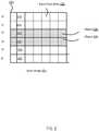
- FIG. 2illustrates an exemplary representation of a timing delay associated with a CMOS imaging system, in accordance with one or more implementations.
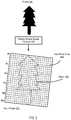
- FIG. 3illustrates an exemplary representation of an input image pixel array associated with an input image, in accordance with one or more implementations.
- FIG. 4illustrates an exemplary schematic of output image determined via iterative image correction process, in accordance with one or more implementations.
- FIG. 5illustrates an exemplary schematic of iterations of performed during iterative image correction process, in accordance with one or more implementations.
- FIG. 6illustrates a method for performing image correction for rolling shutter, in accordance with one or more implementations.
- FIG. 1illustrates system 100 configured to perform image correction for rolling shutter, in accordance with one or more implementations.
- system 100may include one or more image capture device 126 .
- Image capture device 126may be configured to communicate with one or more client computing platforms 104 and/or one or more server(s) according to a client/server architecture.
- the users of system 100may access image capture device 126 directly via image capture device 126 and/or indirectly with one or more server(s) via client computing platform(s) 104 .
- Image capture device 126may be configured to execute one or more computer program components.
- the computer program componentsmay include one or more of input image component 106 , acquisition time component 108 , orientation component 110 , output pixel array component 112 , iteration component 114 and/or other components.
- Image capture device 126may include one or more of a computing platform, a mobile device (e.g., a smart phone, a tablet, and/or other mobile device), a camera (e.g., an action camera, a sports camera, and/or other type of camera), a video recorder, and/or other device configured to capture images and/or video segments.
- Image capture device 126may include one or more sensors including one or more of a GPS, a gyro, a compass, an accelerometer, a temperature sensor, a pressure sensor, a depth sensor, imaging sensor, a sound transducer, and/or other sensors.
- One or more sensorsmay be located external to image capture device 126 and may provide information obtained via the one or more sensors external to image capture device 126 .
- Image capture component 106may be configured to obtain one or more input images captured by one or more imaging sensors of one or more image capture devices.
- an input imagemay be obtained from an imaging sensor of an image capture device.
- One or more imaging sensors used to capture the input imagemay be one or more rigidly mounted active pixel sensors such as CMOS and/or other sensors.
- Such imaging sensorsmay be produced by a complementary metal-oxide-semiconductor (CMOS) technology for constructing integrated circuits and hence may be referred to as the CMOS image sensor.
- CMOScomplementary metal-oxide-semiconductor
- the input image captured by the imaging sensormay comprise an array of pixels.
- the input image captured by the imaging sensormay comprise of photosites or pixels acquired at slightly different moments in time. Contents of pixels in the pixel array may be captured on a row-by-row basis so that contents of an individual row of pixels may be captured after a time delay relative to the acquisition of contents of another row of pixels within the array.
- the rolling shutter configuration described in this applicationinvolves row-by-row capture this is not intended to be limiting, and the concepts described herein are equally applicable to any image sensor that captures or “reads out” photosites or pixels on a subset-by-subset basis regardless of whether or not the subsets are rows.
- Pixels of the pixel arraymay be characterized by pixel contents.
- Pixel contentsmay include pixel position information specifying the individual pixel positions within the pixel array. Pixel position within the array may be expressed in terms of x and y coordinates, and/or other coordinate schemes.
- Contents of pixels in the pixel arraymay include pixel values within the pixel array. Pixel value may include a numeric representation associated with specific colors in a color space (e.g., RGB, CMYK, and/or other color spaces). For example, a pixel having a value of (1, 0, 0) in the RGB color space may be associated with a pure red color. Other types of pixel values may control opacity and/or other information for the pixel.
- the image capture devicemay include a lens.
- the lensmay be configured to provide light waves to the imaging sensor.
- the lensmay be characterized by a lens projection.
- the input imagemay be configured based on the lens projection and the input image may be configured in an equirectangular projection and/or other lens projection.
- the lens projectionmay be characterized by a rectilinear transformation and/or other lens projection.
- the imaging sensorsmay typically capture an image over a time window configured between approximately 4 milliseconds and 1000 milliseconds, depending on an exposure and/or an image frame rate.
- the imaging sensorperforms row-by-row capture of pixel values wherein a given row of pixels of the image may be sampled at a given time.
- the row-to-row delaymay result in a “rolling shutter” effect, where objects in the resultant image (i.e. the input image) may be skewed (tilted to the left or right, depending on the direction of image capture device or subject movement). For example, when tracking a car moving at high speed, the car may not appear distorted but the background may appear tilted.
- images obtained by imaging sensors characterized by row-by-row image acquisition processmay be applicable to other sensor technologies and/or to other image configurations.
- an imaging sensormay comprise two or more imaging sensor components wherein the first imaging sensor component may sense incoming waves (e.g., light, radio frequency waves, pressure waves) at a first time instance, while the second image sensor component may sense the incoming waves at a second time instance, e.g., subsequent to the first time instance.
- wavese.g., light, radio frequency waves, pressure waves
- an imaging sensormay comprise two charge-couple device (CCD) imaging sensor components (e.g., one covering one (e.g., left) portion of a view field and one covering another (e.g., right) portion of the view) configured to acquire pixels at two time instances (e.g., first pixels of one CCD imaging sensor component and subsequently pixels of the other CCD imaging sensor component).
- CCDcharge-couple device
- an imaging sensormay be configured to acquire (scan) a portion of an image at a given time.
- the image portionmay include multiple pixels arranges in a variety of configurations, e.g., multiple rows, partial row, polygon, frame-like, and/or other shapes.
- imaging sensormay be configured to capture images using exposure duration parameter and/or other parameters.
- Exposure duration parametermay be configured in accordance with a variety of parameters, image acquisition rate (frame rate), amount of light (ambient and/or flash), sensor sensitivity setting (e.g., ISO setting), sensor dimension, and/or other parameters.
- exposure timemay be configured from the range between 1/500 of a second to 120 seconds.
- the row-to row acquisition time (transfer time) parametermay be configured based on sensor pixel resolution, frame rate, and/or other imaging sensor parameters; and may be selected between 2 microsecond (us) and 10,000 us.
- Acquisition time component 108may be configured to obtain acquisition time specifying time of capture of one or more sets of pixels within the pixel array of the input image. Pixel acquisition time may be determined using an imaging sensor internal clock and/or imaging sensor configurations. Imaging sensor configurations may determine a maximum frame rate and/or other imaging sensor parameters. Pixel acquisition time may be determined based on image exposure duration and position of the pixel in the image array (pixel row index). By way of a non-limiting illustration, a first acquisition time specifying a time of capture of a first set of pixels may be obtained within a pixel array of the input image. Acquisition time component 108 may be configured to obtain a second acquisition time specifying a time of capture of a second set of pixels within the pixel array of the input image.
- Acquisition time component 108may be configured to associate acquisition time specifying time of capture of one or more sets of pixels within the pixel array with row locations corresponding to pixels in the input image.
- a first acquisition timemay be associated with a first row of the input image.
- Acquisition time component 108may be configured to associate a second acquisition time with a second row of the input image.
- Input image 201illustrates an image of an object, denoted by horizontal lines, obtained with the image capture device.
- Input image 201may comprise input pixel array 202 .
- Input pixel array 202may further comprise rows of pixels 212 , 214 , 216 , 218 , and 220 corresponding to rows of pixels within input pixel array 202 captured by an imaging sensor at acquisition times t 0 , t 1 , t 2 , t 3 , t 4 , and t 5 , respectively.
- Input image 201may comprise representation 206 of the object.
- Input image 201may comprise representation 208 of the object.
- Representation 206may correspond to pixel row 216 of input pixel array 202 of input image 201 .
- Representation 208may correspond to pixel row 218 of input pixel array 202 in input image 201 .
- pixel row 218may occur (e.g., be sampled) subsequent to pixel row 216 relative frame start time (e.g., point in time denoted 203 in FIG. 2 ).
- Object representation 206may correspond to pixels acquired at time instant t 2 and object representation 208 may correspond to pixels acquired at time instant t 3 .
- Time instant t 2may be associated with pixel row 216 having object representation 206 and time instant t 3 may be associated with pixel row 218 having object representation 208 .
- orientation component 110may be configured to obtain one or more orientation information specifying imaging sensor orientations at the acquisition times of the sets of input pixels within the input pixel array.
- a first orientation information specifying a first imaging sensor orientationmay be obtained at a first acquisition time of a first set of pixels of the input image.
- Orientation component 110may be configured to obtain a second orientation information specifying a second imaging sensor orientation at a second acquisition time of a second set of pixels with a row of pixels of the input image.
- Orientation component 110may be configured to obtain orientation information based on an analysis of the first pixel row of the input image and the second pixel row of the input image.
- orientation component 110may be configured to be coupled to an orientation sensor.
- the orientation sensormay comprise one or more of a gyroscope, accelerometer, and/or other orientation sensors.
- the orientation sensormay be configured to provide orientation information.
- the orientation sensormay comprise one or more of a gyroscope, accelerometer, and/or other orientation sensors.
- the motion of the image capture devicemay cause changes in the image capture device orientation when different portions (e.g., different rows) of the input image are captured.
- Imagesmay reflect image capture device movements during image acquisition, which may result in image deformities caused by changes in orientation of the imaging sensor at the pixel acquisition time instance.
- object 301may be captured by an image device having using an imaging sensor that performs row-by-row capture of pixel values wherein a given row of pixels within input pixel array 323 of resulting input image 321 may be sampled at a given time.
- the motion and/or orientation change of the image capture device during the image capture processmay result in a deformed or skewed input image pixel array 323 in relation to object 301 .
- Image deformitiesmay be corrected by determining the changes in orientation of the sensor at the pixel acquisition time instance. Obtaining orientation of the imaging sensor at the pixel acquisition time instance may be used in correcting the input image deformities associated with the motion of the image capture devise. It will be recognized by those skilled in the arts that various other image characteristics configured for individual input images, including but not limited to lens aperture, exposure value, depth of focus, color content, image sharpness, saturation, white balance, field of view, resolution, image size, lens projection (e.g., equirectangular, rectilinear), and/or other parameters may be used when correcting image deformities.
- Image capture device imaging sensor orientation R(y), at the time of capturing a given row of the image (row y),may depend on the image capture device's rotation and transfer time (the time between the capture of subsequent rows in the image capture device).
- the transfer timemay be determined during image capture device manufacturing and/or testing.
- the transfer timemay be estimated by minimizing the projection error of overlapping parts of two or more source images. The projection error may be determined based on a measured of an average distance between matched control points using a key point detector methodology, such as SIFT-based key point detector methodology and/or other methodology.
- an interpolation processmay be applied to the orientation information in order to obtain orientation corresponding to the row acquisition time instant.
- the interpolation processmay include selection of a closest in time value, linear interpolation, quadratic interpolation and/or other method.
- Output pixel array component 112may be configured to determine an output pixel array based on the input image.
- the output pixel arraymay represent a pixel array of the input image obtained by input image component 106 that has been transformed to account for changes in the imaging sensor orientation at different acquisition times, as described in U.S. patent application Ser. No. 15/387,468, which is incorporated by reference in its entirety.
- a first output cellmay be determined based on a first orientation information specifying a first imaging sensor orientation obtained at a first acquisition time of first set of pixels of the input image.
- Output pixel array component 112may be configured to determine a second output cell based on differences between the first output cell (determined based on the first orientation information specifying the first imaging sensor orientation obtained at the first acquisition time of first set of pixels of the input image) and a second orientation information specifying a second imaging sensor orientation obtained at a second acquisition time of a second pixel of the input image.
- Iteration component 114may be configured to determine an output image based on the output pixel array and the input image.
- the output imagemay represent corrected input image obtained by input image component 106 by determining a location of a pixel within the input image corresponding to a location of a pixel within the output pixel array obtained by output pixel array component 112 by performing one or more fixed point iterations.
- Iteration component 114may be configured to determine pixel locations on a sensor line y within the input image using imaging sensor orientations R(y) at a time the imaging sensor has acquired a row of pixels in the input image corresponding to the output cell within the output pixel array. Iteration component 114 may be configured to determine pixel locations on an imaging sensor line y within the input image by performing one or more fixed point iterations.
- Number of iterations Nmay be selected between 3 and 11, in some implementations.
- number of iterationsmay be determined on a difference between sensor line y n of a given iteration and sensor line y n ⁇ 1 of a preceding iteration. Number of iterations may be limited until no significant difference between successive y n is found.
- imaging sensor orientation R(y)may be used by iteration component 114 .
- a pixelmay be selected in the output pixel array.
- a corresponding row y n+1 of the input imagemay be determined using fixed point iteration process.
- iterative processmay determine pixel locations within input image 421 using imaging sensor orientations at a time an imaging sensor has acquired a row of pixels in input image 421 corresponding to output pixel 403 within the output pixel array 401 .
- Output pixel 403 within output pixel array 401may be acquired at time 423 .
- Output pixel 403may be located on sensor line 413 within output pixel array 401 .
- sensor line 413may be acquired at acquisition time 425 within input image 421 .
- Imaging sensor orientation at acquisition time 425may be interpolated as 431 and output pixel 403 may correspond to pixel 409 within input image 421 with orientation 431 .
- Pixel 409may be located on sensor line 423 within input image 421 .
- sensor line 423may be acquired at acquisition time 427 within input image 421 .
- Imaging sensor orientation acquired at acquisition time 427may be interpolated as 435 and output pixel 403 may correspond to pixel 411 within input image 421 with orientation 435 .
- Pixel 411may be located on sensor line 433 within input image 421 .
- iteration component 114may be configured to determine output pixel positions by performing one or more fixed point iterations to identify one or more input pixels within the input image that correspond to one or more pixels in the output pixel array. Iteration component 114 may be configured to determine output pixel values based on pixel values of the input image.
- output image 521may represent a corrected input image 501 such that image deformities caused by changes in imaging sensor orientation have been corrected.
- Output image 521may include output pixel array 515 .
- Output pixel array 515may comprise one or more output pixels, such as output pixel 510 , as illustrated by FIG. 5 .
- Output pixel 510may be characterized by a position within output pixel array 515 and an output pixel value.
- Output pixel 510may be positioned within output pixel array 515 at sensor line 505 .
- Output pixel position 505may be determined by performing one or more fixed point iterations within input image 501 and correspond to pixel 508 located at sensor line 503 of input pixel array 513 of input image 501 (e.g., as illustrated in FIG. 4 ).
- the value of output pixel 510 of output image 521may be determine based on a value of input pixel 508 of input image 501 .
- image capture device 126 , client computing platform(s) 104 , and/or external resources 120may be operatively linked via one or more electronic communication links.
- electronic communication linksmay be established, at least in part, via network 103 such as the Internet and/or other networks. It will be appreciated that this is not intended to be limiting, and that the scope of this disclosure includes implementations in which image capture device 126 , client computing platform(s) 104 , and/or external resources 120 may be operatively linked via some other communication media.
- a given client computing platform 104may include one or more processors configured to execute computer program components.
- the computer program componentsmay be configured to enable a producer and/or user associated with the given client computing platform 104 to interface with system 100 and/or external resources 120 , and/or provide other functionality attributed herein to client computing platform(s) 104 .
- the given client computing platform 104may include one or more of a desktop computer, a laptop computer, a handheld computer, a NetBook, a Smartphone, a gaming console, and/or other computing platforms.
- External resources 120may include sources of information, hosts and/or providers of virtual environments outside of system 100 , external entities participating with system 100 , and/or other resources. In some implementations, some or all of the functionality attributed herein to external resources 120 may be provided by resources included in system 100 .
- Image capture device 126may include electronic storage 122 , one or more processors 124 , and/or other components. Image capture device 126 may include communication lines, or ports to enable the exchange of information with a network and/or other computing platforms. Illustration of image capture device 126 FIG. 1 is not intended to be limiting. Image capture device 126 may include a plurality of hardware, software, and/or firmware components operating together to provide the functionality attributed herein to image capture device 126 .
- Electronic storage 122may include electronic storage media that electronically stores information.
- the electronic storage media of electronic storage 122may include one or both of system storage that is provided integrally (i.e., substantially non-removable) with image capture device 126 and/or removable storage that is connectable to image capture device 126 via, for example, a port (e.g., a USB port, a Firewire port, etc.) or a drive (e.g., a disk drive, etc.).
- a porte.g., a USB port, a Firewire port, etc.
- a drivee.g., a disk drive, etc.
- Electronic storage 122may include one or more of optically readable storage media (e.g., optical disks, etc.), magnetically readable storage media (e.g., magnetic tape, magnetic hard drive, floppy drive, etc.), electrical charge-based storage media (e.g., EEPROM, RAM, etc.), solid-state storage media (e.g., flash drive, etc.), and/or other electronically readable storage media.
- optically readable storage mediae.g., optical disks, etc.
- magnetically readable storage mediae.g., magnetic tape, magnetic hard drive, floppy drive, etc.
- electrical charge-based storage mediae.g., EEPROM, RAM, etc.
- solid-state storage mediae.g., flash drive, etc.
- Electronic storage 122may be a separate component within image capture device 126 , or electronic storage 122 may be provided integrally with one or more other components of within image capture device 126 (e.g., processor 124 ). Although electronic storage 122 is shown in FIG. 1 as a single entity, this is for illustrative purposes only. In some implementations, electronic storage 122 may comprise a plurality of storage units. These storage units may be physically located within the same device, or electronic storage 122 may represent storage functionality of a plurality of devices operating in coordination. Electronic storage 122 may include one or more virtual storage resources (e.g., cloud storage, a virtual private network, and/or other virtual storage resources). Electronic storage 122 may store software algorithms, information determined by processor(s) 124 , information received from image capture device 126 , information received from client computing platform(s) 104 , and/or other information that enables system 100 to function as described herein.
- virtual storage resourcese.g., cloud storage, a virtual private network, and/or other virtual storage resources
- Processor(s) 124may be configured to provide information processing capabilities in image capture device 126 .
- processor(s) 124may include one or more of a digital processor, an analog processor, a digital circuit designed to process information, an analog circuit designed to process information, a state machine, and/or other mechanisms for electronically processing information.
- processor(s) 124is shown in FIG. 1 as a single entity, this is for illustrative purposes only.
- processor(s) 124may include a plurality of processing units. These processing units may be physically located within the same device, or processor(s) 124 may represent processing functionality of a plurality of devices operating in coordination.
- the processor(s) 124may be configured to execute computer readable instruction components 106 , 108 , 110 , 112 , 114 and/or other components.
- the processor(s) 124may be configured to execute components 106 , 108 , 110 , 112 , 114 and/or other components by software; hardware; firmware; some combination of software, hardware, and/or firmware; and/or other mechanisms for configuring processing capabilities on processor(s) 124 .
- components 106 , 108 , 110 , 112 and/or 114are illustrated in FIG. 1 as being co-located within a single processing unit, in implementations in which processor(s) 124 includes multiple processing units, one or more of components 106 , 108 , 110 , 112 and/or 114 may be located remotely from the other components.
- the description of the functionality provided by the different components 106 , 108 , 110 , 112 and/or 114 described hereinis for illustrative purposes, and is not intended to be limiting, as any of components 106 , 108 , 110 , 112 and/or 114 may provide more or less functionality than is described.
- processor(s) 124may be configured to execute one or more additional components that may perform some or all of the functionality attributed herein to one of components 106 , 108 , 110 , 112 and/or 114 .
- FIG. 6illustrates a method 600 for performing image correction for rolling shutter, in accordance with one or more implementations.
- the operations of method 600 presented beloware intended to be illustrative. In some implementations, method 600 may be accomplished with one or more additional operations not described, and/or without one or more of the operations discussed. Additionally, the order in which the operations of method 600 are illustrated in FIG. 6 and described below is not intended to be limiting.
- method 600may be implemented in one or more processing devices (e.g., a digital processor, an analog processor, a digital circuit designed to process information, an analog circuit designed to process information, a state machine, and/or other mechanisms for electronically processing information).
- the one or more processing devicesmay include one or more devices executing some or all of the operations of method 600 in response to instructions stored electronically on an electronic storage medium.
- the one or more processing devicesmay include one or more devices configured through hardware, firmware, and/or software to be specifically designed for execution of one or more of the operations of method 600 .
- an input image array of an input image captured by an imaging sensor an imaging capture devicemay be obtained. Operation 602 may be performed by one or more physical processors executing an input image component that is the same as or similar to input image component 106 , in accordance with one or more implementations.
- a first acquisition time specifying capture times of a first pixel within the pixel arraymay be obtained and/or a second acquisition time specifying capture times of a second pixel within the pixel array may be obtained.
- Operation 604may be performed by one or more physical processors executing an acquisition time component that is the same as or similar to acquisition time component 108 , in accordance with one or more implementations.
- a first orientation information specifying imaging sensor orientation at the first acquisition time of the first pixelmay be obtained and/or a second orientation information specifying imaging sensor orientation at the second acquisition time of the second pixel may be obtained.
- Operation 606may be performed by one or more physical processors executing an orientation component that is the same as or similar to orientation component 110 , in accordance with one or more implementations.
- an output pixel array of output cells based on the input pixel arraymay be determined.
- the cells of the output pixel arraymay be transformed based on differences between imaging sensor orientations at the different acquisition times within the input image.
- Operation 608may be performed by one or more physical processors executing an output pixel array component that is the same as or similar to output pixel array component 112 , in accordance with one or more implementations.
- one or more fixed point iterations to identify one or more input pixels within the input pixel array of the input image that corresponds to one the output pixelsmay be performed.
- a value of the output pixel based on a value of a corresponding pixel within the input imagemay be determined. Operations 610 and 612 may be performed by one or more physical processors executing an iteration component that is the same as or similar to iteration component 114 , in accordance with one or more implementations.
Landscapes
- Engineering & Computer Science (AREA)
- Multimedia (AREA)
- Signal Processing (AREA)
- Physics & Mathematics (AREA)
- General Physics & Mathematics (AREA)
- Theoretical Computer Science (AREA)
- Studio Devices (AREA)
Abstract
Description
Claims (20)
Priority Applications (1)
| Application Number | Priority Date | Filing Date | Title |
|---|---|---|---|
| US16/784,656US10893223B2 (en) | 2017-02-22 | 2020-02-07 | Systems and methods for rolling shutter compensation using iterative process |
Applications Claiming Priority (4)
| Application Number | Priority Date | Filing Date | Title |
|---|---|---|---|
| US15/439,257US10194101B1 (en) | 2017-02-22 | 2017-02-22 | Systems and methods for rolling shutter compensation using iterative process |
| US16/257,290US10412328B2 (en) | 2017-02-22 | 2019-01-25 | Systems and methods for rolling shutter compensation using iterative process |
| US16/538,631US10560648B2 (en) | 2017-02-22 | 2019-08-12 | Systems and methods for rolling shutter compensation using iterative process |
| US16/784,656US10893223B2 (en) | 2017-02-22 | 2020-02-07 | Systems and methods for rolling shutter compensation using iterative process |
Related Parent Applications (1)
| Application Number | Title | Priority Date | Filing Date |
|---|---|---|---|
| US16/538,631ContinuationUS10560648B2 (en) | 2017-02-22 | 2019-08-12 | Systems and methods for rolling shutter compensation using iterative process |
Publications (2)
| Publication Number | Publication Date |
|---|---|
| US20200177827A1 US20200177827A1 (en) | 2020-06-04 |
| US10893223B2true US10893223B2 (en) | 2021-01-12 |
Family
ID=65032736
Family Applications (4)
| Application Number | Title | Priority Date | Filing Date |
|---|---|---|---|
| US15/439,257Active2037-04-16US10194101B1 (en) | 2017-02-22 | 2017-02-22 | Systems and methods for rolling shutter compensation using iterative process |
| US16/257,290ActiveUS10412328B2 (en) | 2017-02-22 | 2019-01-25 | Systems and methods for rolling shutter compensation using iterative process |
| US16/538,631ActiveUS10560648B2 (en) | 2017-02-22 | 2019-08-12 | Systems and methods for rolling shutter compensation using iterative process |
| US16/784,656ActiveUS10893223B2 (en) | 2017-02-22 | 2020-02-07 | Systems and methods for rolling shutter compensation using iterative process |
Family Applications Before (3)
| Application Number | Title | Priority Date | Filing Date |
|---|---|---|---|
| US15/439,257Active2037-04-16US10194101B1 (en) | 2017-02-22 | 2017-02-22 | Systems and methods for rolling shutter compensation using iterative process |
| US16/257,290ActiveUS10412328B2 (en) | 2017-02-22 | 2019-01-25 | Systems and methods for rolling shutter compensation using iterative process |
| US16/538,631ActiveUS10560648B2 (en) | 2017-02-22 | 2019-08-12 | Systems and methods for rolling shutter compensation using iterative process |
Country Status (1)
| Country | Link |
|---|---|
| US (4) | US10194101B1 (en) |
Families Citing this family (2)
| Publication number | Priority date | Publication date | Assignee | Title |
|---|---|---|---|---|
| US10194101B1 (en)* | 2017-02-22 | 2019-01-29 | Gopro, Inc. | Systems and methods for rolling shutter compensation using iterative process |
| EP3929864A1 (en) | 2020-06-23 | 2021-12-29 | Prophesee | Image enhancement method, apparatus and system |
Citations (126)
| Publication number | Priority date | Publication date | Assignee | Title |
|---|---|---|---|---|
| US5260779A (en) | 1992-02-21 | 1993-11-09 | Control Automation, Inc. | Method and apparatus for inspecting a printed circuit board |
| EP0605045A1 (en) | 1992-12-29 | 1994-07-06 | Laboratoires D'electronique Philips S.A.S. | Image processing method and apparatus for generating one image from adjacent images |
| EP0650299A1 (en) | 1993-10-20 | 1995-04-26 | Laboratoires D'electronique Philips S.A.S. | Image processing system comprising fixed cameras and a system simulating a moving camera |
| EP0661672A1 (en) | 1993-12-29 | 1995-07-05 | Laboratoires D'electronique Philips S.A.S. | Picture processing process and device for building a target image from a source image with perspective change |
| US5555895A (en) | 1993-01-29 | 1996-09-17 | Centre National De La Recherche Scientifique | Process and device for eye movement analysis |
| US6434265B1 (en) | 1998-09-25 | 2002-08-13 | Apple Computers, Inc. | Aligning rectilinear images in 3D through projective registration and calibration |
| US20020112005A1 (en) | 1998-08-25 | 2002-08-15 | Charles Namias | Video e-mail kiosk |
| US20020122113A1 (en) | 1999-08-09 | 2002-09-05 | Foote Jonathan T. | Method and system for compensating for parallax in multiple camera systems |
| US6486908B1 (en) | 1998-05-27 | 2002-11-26 | Industrial Technology Research Institute | Image-based method and system for building spherical panoramas |
| US20020191087A1 (en) | 1996-04-15 | 2002-12-19 | Canon Kabushiki Kaisha | Communication apparatus and method that link a network address with designated image information |
| US20030085992A1 (en) | 2000-03-07 | 2003-05-08 | Sarnoff Corporation | Method and apparatus for providing immersive surveillance |
| US20030098954A1 (en) | 2001-04-27 | 2003-05-29 | International Business Machines Corporation | Calibration-free eye gaze tracking |
| US20030160862A1 (en) | 2002-02-27 | 2003-08-28 | Charlier Michael L. | Apparatus having cooperating wide-angle digital camera system and microphone array |
| US20040010804A1 (en) | 1996-09-04 | 2004-01-15 | Hendricks John S. | Apparatus for video access and control over computer network, including image correction |
| US20040017492A1 (en) | 2002-07-29 | 2004-01-29 | Stavely Donald J. | Apparatus and method for improved-resolution digital zoom in an electronic imaging device |
| US20040021780A1 (en) | 2002-07-31 | 2004-02-05 | Intel Corporation | Method and apparatus for automatic photograph annotation with contents of a camera's field of view |
| US20040047606A1 (en) | 2002-09-09 | 2004-03-11 | Canon Kabushiki Kaisha | Image recording apparatus capable of recording information associated with location upon image sensing together with sensed image data, and control method thereof |
| US6711293B1 (en) | 1999-03-08 | 2004-03-23 | The University Of British Columbia | Method and apparatus for identifying scale invariant features in an image and use of same for locating an object in an image |
| US6710740B2 (en) | 2002-03-04 | 2004-03-23 | Intel Corporation | Recording-location determination |
| US20040075738A1 (en) | 1999-05-12 | 2004-04-22 | Sean Burke | Spherical surveillance system architecture |
| US20040135900A1 (en) | 2003-01-15 | 2004-07-15 | Hewlett Packard Company | Method and apparatus for capture of sensory data in association with image data |
| US20040169724A1 (en) | 2002-12-09 | 2004-09-02 | Ekpar Frank Edughom | Method and apparatus for creating interactive virtual tours |
| US6788333B1 (en) | 2000-07-07 | 2004-09-07 | Microsoft Corporation | Panoramic video |
| US20050033760A1 (en) | 1998-09-01 | 2005-02-10 | Charles Fuller | Embedded metadata engines in digital capture devices |
| US20050062869A1 (en) | 1999-04-08 | 2005-03-24 | Zimmermann Steven Dwain | Immersive video presentations |
| US20050104976A1 (en) | 2003-11-17 | 2005-05-19 | Kevin Currans | System and method for applying inference information to digital camera metadata to identify digital picture content |
| US20050134707A1 (en) | 2003-12-18 | 2005-06-23 | Eastman Kodak Company | Image metadata attachment |
| US20050289111A1 (en) | 2004-06-25 | 2005-12-29 | Tribble Guy L | Method and apparatus for processing metadata |
| US20060050997A1 (en) | 2004-09-09 | 2006-03-09 | Casio Computer Co., Ltd. | Camera device with movie capture function |
| US7057663B1 (en) | 2001-05-17 | 2006-06-06 | Be Here Corporation | Audio synchronization pulse for multi-camera capture systems |
| US20070030358A1 (en) | 2005-07-19 | 2007-02-08 | Canon Kabushiki Kaisha | Image-processing device, method for controlling same, computer program, and storage medium |
| US20070053659A1 (en) | 2003-10-10 | 2007-03-08 | Jiro Kiyama | Reproducing apparatus, method for controlling reproducing apparatus, content recording medium, data structure, control program, computer-readable recording medium storing control program |
| US20070120986A1 (en) | 2005-11-08 | 2007-05-31 | Takashi Nunomaki | Imaging device, information processing method, and computer program |
| US20070140662A1 (en) | 2005-11-08 | 2007-06-21 | Takashi Nunomaki | Information processing apparatus, imaging device, information processing method, and computer program |
| US20070154202A1 (en) | 2006-01-04 | 2007-07-05 | Lee King F | Method and apparatus to facilitate correcting rolling shutter images |
| US20070300249A1 (en) | 2006-06-22 | 2007-12-27 | Smith Kevin P | In-band data recognition and synchronization system |
| US20080094499A1 (en) | 2005-12-07 | 2008-04-24 | Sony Corporation | Imaging apparatus, data recording method and data-display control method, and computer program |
| US20080118100A1 (en) | 2006-11-20 | 2008-05-22 | Canon Kabushiki Kaisha | Information processing apparatus and control method thereof, and computer readable storage medium |
| WO2009047572A1 (en) | 2007-10-09 | 2009-04-16 | Analysis Systems Research High-Tech S.A. | Integrated system, method and application for the synchronized interactive play-back of multiple spherical video content and autonomous product for the interactive play-back of prerecorded events. |
| US20090160957A1 (en) | 2007-12-20 | 2009-06-25 | Micron Technology, Inc. | Methods and system for digitally stabilizing video captured from rolling shutter cameras |
| US20090202177A1 (en) | 2008-02-07 | 2009-08-13 | Eric Jeffrey | Non-Uniform Image Resizer |
| US20090210707A1 (en) | 2006-05-15 | 2009-08-20 | Paolo De Lutiis | Out-of Band Authentication Method and System for Communication Over a Data Network |
| US20090251558A1 (en) | 2008-04-04 | 2009-10-08 | Samsung Techwin Co., Ltd. | Fast and low-power digital camera with gps |
| US20090262206A1 (en) | 2008-04-16 | 2009-10-22 | Johnson Controls Technology Company | Systems and methods for providing immersive displays of video camera information from a plurality of cameras |
| US20090271447A1 (en) | 2008-04-28 | 2009-10-29 | Shin Kang Soo | Method for synchronizing contents file and device for employing the same |
| US20100045773A1 (en) | 2007-11-06 | 2010-02-25 | Ritchey Kurtis J | Panoramic adapter system and method with spherical field-of-view coverage |
| US20100097443A1 (en) | 2008-10-16 | 2010-04-22 | Peter Lablans | Controller in a Camera for Creating a Panoramic Image |
| WO2010073192A1 (en) | 2008-12-23 | 2010-07-01 | Koninklijke Philips Electronics N.V. | Image scaling curve generation |
| US20100238304A1 (en) | 2009-03-18 | 2010-09-23 | Casio Computer Co., Ltd. | Digital camera for recording still image with speech |
| US20100250022A1 (en) | 2006-12-29 | 2010-09-30 | Air Recon, Inc. | Useful unmanned aerial vehicle |
| US20100289924A1 (en) | 2009-05-14 | 2010-11-18 | Hoya Corporation | Imager that adds visual effects to an image |
| US20100299630A1 (en) | 2009-05-22 | 2010-11-25 | Immersive Media Company | Hybrid media viewing application including a region of interest within a wide field of view |
| US20110013778A1 (en) | 2004-06-23 | 2011-01-20 | Yamaha Corporation | Speaker array apparatus and method for setting audio beams of speaker array appratus |
| US20110115883A1 (en) | 2009-11-16 | 2011-05-19 | Marcus Kellerman | Method And System For Adaptive Viewport For A Mobile Device Based On Viewing Angle |
| EP2334058A1 (en) | 2008-09-28 | 2011-06-15 | Huawei Device Co., Ltd. | Image zooming method and apparatus |
| US20110141300A1 (en) | 2009-12-11 | 2011-06-16 | Fotonation Ireland Limited | Panorama Imaging Using a Blending Map |
| US7983502B2 (en) | 2007-08-06 | 2011-07-19 | Microsoft Corporation | Viewing wide angle images using dynamic tone mapping |
| US20110176043A1 (en) | 2010-01-21 | 2011-07-21 | Microsoft Corporation | Reducing Motion-Related Artifacts in Rolling Shutter Video Information |
| US20110176014A1 (en) | 2010-01-18 | 2011-07-21 | Wei Hong | Video Stabilization and Reduction of Rolling Shutter Distortion |
| US20110261227A1 (en) | 2008-09-12 | 2011-10-27 | Nikon Corporation | Imaging apparatus |
| US20110267514A1 (en) | 2010-04-30 | 2011-11-03 | Ecole Polytechnique Federale De Lausanne | Method to compensate the effect of the rolling shutter effect |
| US20120092559A1 (en) | 2010-10-19 | 2012-04-19 | Apple Inc. | Rolling Shutter Distortion Correction |
| US20120242798A1 (en) | 2011-01-10 | 2012-09-27 | Terrence Edward Mcardle | System and method for sharing virtual and augmented reality scenes between users and viewers |
| US20130021450A1 (en) | 2011-07-22 | 2013-01-24 | Yasuo Yoshizawa | Stereoscopic imaging system, recording control method, stereoscopic image reproduction system, and reproduction control method |
| US20130058619A1 (en) | 2011-09-02 | 2013-03-07 | Nikon Corporation | Imaging device and image-audio playback device |
| US20130058532A1 (en) | 2007-03-05 | 2013-03-07 | Sportvision, Inc. | Tracking An Object With Multiple Asynchronous Cameras |
| US20130127903A1 (en) | 2009-02-26 | 2013-05-23 | Sylvain Paris | System and Method for Reducing the Appearance of Residuals in Gradient-Based Image Compositing |
| US20130176403A1 (en) | 2011-08-16 | 2013-07-11 | Kenneth Varga | Heads up display (HUD) sensor system |
| US20130177168A1 (en) | 2009-12-24 | 2013-07-11 | Nokia Corporation | Apparatus |
| US20130182177A1 (en) | 2012-01-18 | 2013-07-18 | John Furlan | Systems and methods for improving video stutter in high resolution progressive video |
| US20130210563A1 (en) | 2009-05-02 | 2013-08-15 | Steven J. Hollinger | Ball with camera for reconnaissance or recreation and network for operating the same |
| US20130235226A1 (en) | 2012-03-12 | 2013-09-12 | Keith Stoll Karn | Digital camera having low power capture mode |
| US8606073B2 (en) | 2010-05-12 | 2013-12-10 | Woodman Labs, Inc. | Broadcast management system |
| US20140037268A1 (en) | 2012-08-03 | 2014-02-06 | Canon Kabushiki Kaisha | Moving image recording apparatus capable of recording moving images to recording media, and control method and storage medium therefor |
| US20140039884A1 (en) | 2001-12-14 | 2014-02-06 | Microsoft Corporation | Quality improvement techniques in an audio encoder |
| US8670030B2 (en) | 2010-05-25 | 2014-03-11 | Olympus Imaging Corp. | Photographing device and control method therefor |
| US20140071299A1 (en) | 2012-09-12 | 2014-03-13 | Google Inc. | Methods and Systems for Removal of Rolling Shutter Effects |
| WO2014090277A1 (en) | 2012-12-10 | 2014-06-19 | Nokia Corporation | Spatial audio apparatus |
| US20140240122A1 (en) | 2014-02-27 | 2014-08-28 | Fitbit, Inc. | Notifications on a User Device Based on Activity Detected By an Activity Monitoring Device |
| US8842197B2 (en) | 2005-11-30 | 2014-09-23 | Scenera Mobile Technologies, Llc | Automatic generation of metadata for a digital image based on ambient conditions |
| US8890954B2 (en) | 2010-09-13 | 2014-11-18 | Contour, Llc | Portable digital video camera configured for remote image acquisition control and viewing |
| US20150058102A1 (en) | 2013-08-21 | 2015-02-26 | Jaunt Inc. | Generating content for a virtual reality system |
| US9019396B2 (en) | 2012-04-19 | 2015-04-28 | Olympus Corporation | Wireless communication device, memory device, wireless communication system, wireless communication method, and program recordable medium |
| US20150142211A1 (en) | 2012-05-04 | 2015-05-21 | Aeryon Labs Inc. | System and method for controlling unmanned aerial vehicles |
| US20150142742A1 (en) | 2013-11-17 | 2015-05-21 | Zhen-Chao HONG | System and method for syncing local directories that enable file access across multiple devices |
| US20150166476A1 (en) | 2013-12-17 | 2015-06-18 | Yi-Cheng Chen | Methods for treating neurodegenerative diseases associated with aggregation of amyloid-beta |
| US20150186073A1 (en) | 2013-12-30 | 2015-07-02 | Lyve Minds, Inc. | Integration of a device with a storage network |
| US20150189221A1 (en) | 2013-12-26 | 2015-07-02 | Canon Kabushiki Kaisha | Image reproducing apparatus and method for controlling same |
| US20150287435A1 (en) | 2014-04-04 | 2015-10-08 | Red.Com, Inc. | Video camera with capture modes |
| US20150288754A1 (en) | 2014-04-07 | 2015-10-08 | Palo Alto Research Center Incorporated | Service discovery using collection synchronization with exact names |
| US9158304B2 (en) | 2013-11-10 | 2015-10-13 | Google Inc. | Methods and systems for alerting and aiding an emergency situation |
| US20150304532A1 (en) | 2014-04-18 | 2015-10-22 | Alarm.Com Incorporated | Pan and tilt camera with robotic movement |
| US20150336015A1 (en) | 2014-05-21 | 2015-11-26 | Universal City Studios Llc | Ride vehicle tracking and control system using passive tracking elements |
| US20150350614A1 (en) | 2012-08-31 | 2015-12-03 | Brain Corporation | Apparatus and methods for tracking using aerial video |
| US20150363648A1 (en) | 2014-06-11 | 2015-12-17 | Arris Enterprises, Inc. | Detection of demarcating segments in video |
| US20150367958A1 (en) | 2014-06-20 | 2015-12-24 | nearmap australia pty ltd. | Wide-area aerial camera systems |
| US20150370250A1 (en) | 2014-06-19 | 2015-12-24 | Skydio, Inc. | Magic wand interface and other user interaction paradigms for a flying digital assistant |
| US20160018822A1 (en) | 2014-07-18 | 2016-01-21 | Helico Aerospace Industries Sia | Autonomous vehicle operation |
| US20160031559A1 (en) | 2014-07-30 | 2016-02-04 | SZ DJI Technology Co., Ltd | Systems and methods for target tracking |
| US20160054737A1 (en) | 2014-08-22 | 2016-02-25 | Cape Productions Inc. | Methods and Apparatus for Unmanned Aerial Vehicle Autonomous Aviation |
| US20160076892A1 (en) | 2014-03-24 | 2016-03-17 | SZ DJI Technology Co., Ltd | Methods and systems for determining a state of an unmanned aerial vehicle |
| US20160098469A1 (en) | 2014-10-07 | 2016-04-07 | Yahoo! Inc. | Method and system for providing a synchronization service |
| US20160101856A1 (en) | 2014-06-23 | 2016-04-14 | Nixie Labs, Inc. | Wearable unmanned aerial vehicles, and associated systems and methods |
| US20160112713A1 (en) | 2014-10-20 | 2016-04-21 | Google Inc. | Mapping spherical image to 2d representations |
| US20160129999A1 (en) | 2014-11-07 | 2016-05-12 | Paccar Inc | Drone systems for pre-trip inspection and assisted backing |
| US20160139596A1 (en) | 2014-11-14 | 2016-05-19 | Lg Electronics Inc. | Mobile terminal and controlling method thereof |
| US20160165563A1 (en) | 2013-07-31 | 2016-06-09 | Samsung Electronics Co., Ltd. | Method and apparatus for time synchronization in device-to-device communication |
| US20160179096A1 (en) | 2014-05-23 | 2016-06-23 | Lily Robotics, Inc. | Launching unmanned aerial copter from mid-air |
| US20160189101A1 (en) | 2014-05-20 | 2016-06-30 | Verizon Patent And Licensing Inc. | Secure payload deliveries via unmanned aerial vehicles |
| US20160234438A1 (en) | 2015-02-06 | 2016-08-11 | Tetsuya Satoh | Image processing system, image generation apparatus, and image generation method |
| US20160239340A1 (en) | 2015-02-13 | 2016-08-18 | International Business Machines Corporation | Determining an ordering to use to open and close programs that call other programs |
| US20160269621A1 (en) | 2015-03-13 | 2016-09-15 | Center For Integrated Smart Sensors Foundation | Front-end event detector and low-power camera system using thereof |
| US20160295108A1 (en) | 2015-04-01 | 2016-10-06 | Cheng Cao | System and method for panoramic imaging |
| US9473758B1 (en) | 2015-12-06 | 2016-10-18 | Sliver VR Technologies, Inc. | Methods and systems for game video recording and virtual reality replay |
| US20160304198A1 (en) | 2014-12-03 | 2016-10-20 | Google Inc. | Systems and methods for reliable relative navigation and autonomous following between unmanned aerial vehicle and a target object |
| US20160306351A1 (en) | 2015-04-14 | 2016-10-20 | Vantage Robotics, Llc | System for authoring, executing, and distributing unmanned aerial vehicle flight-behavior profiles |
| US20160313734A1 (en) | 2015-04-21 | 2016-10-27 | Gopro, Inc. | Return Path Configuration For Remote Controlled Aerial Vehicle |
| US20160327950A1 (en) | 2014-06-19 | 2016-11-10 | Skydio, Inc. | Virtual camera interface and other user interaction paradigms for a flying digital assistant |
| US20160336020A1 (en) | 2015-05-11 | 2016-11-17 | Lily Robotics, Inc. | External microphone for an unmanned aerial vehicle |
| US20160366290A1 (en) | 2015-06-11 | 2016-12-15 | Casio Computer Co., Ltd. | Image shooting apparatus for adding information to image |
| US20170048334A1 (en) | 2014-05-27 | 2017-02-16 | Panasonic Intellectual Property Management Co., Ltd. | Method for sharing photographed images between users |
| US9602795B1 (en) | 2016-02-22 | 2017-03-21 | Gopro, Inc. | System and method for presenting and viewing a spherical video segment |
| US20170236257A1 (en) | 2012-04-06 | 2017-08-17 | Microsoft Technology Licensing, Llc | Joint Video Stabilization and Rolling Shutter Correction on a Generic Platform |
| US20170272668A1 (en) | 2016-03-18 | 2017-09-21 | Raytheon Company | Methods and system for geometric distortion correction for space-based rolling-shutter framing sensors |
| US20170332018A1 (en) | 2016-05-10 | 2017-11-16 | Nvidia Corporation | Real-time video stabilization for mobile devices based on on-board motion sensing |
| US10194101B1 (en)* | 2017-02-22 | 2019-01-29 | Gopro, Inc. | Systems and methods for rolling shutter compensation using iterative process |
Family Cites Families (2)
| Publication number | Priority date | Publication date | Assignee | Title |
|---|---|---|---|---|
| US9930225B2 (en) | 2011-02-10 | 2018-03-27 | Villmer Llc | Omni-directional camera and related viewing software |
| US9570113B2 (en) | 2014-07-03 | 2017-02-14 | Gopro, Inc. | Automatic generation of video and directional audio from spherical content |
- 2017
- 2017-02-22USUS15/439,257patent/US10194101B1/enactiveActive
- 2019
- 2019-01-25USUS16/257,290patent/US10412328B2/enactiveActive
- 2019-08-12USUS16/538,631patent/US10560648B2/enactiveActive
- 2020
- 2020-02-07USUS16/784,656patent/US10893223B2/enactiveActive
Patent Citations (133)
| Publication number | Priority date | Publication date | Assignee | Title |
|---|---|---|---|---|
| US5260779A (en) | 1992-02-21 | 1993-11-09 | Control Automation, Inc. | Method and apparatus for inspecting a printed circuit board |
| EP0605045A1 (en) | 1992-12-29 | 1994-07-06 | Laboratoires D'electronique Philips S.A.S. | Image processing method and apparatus for generating one image from adjacent images |
| US5555895A (en) | 1993-01-29 | 1996-09-17 | Centre National De La Recherche Scientifique | Process and device for eye movement analysis |
| EP0650299A1 (en) | 1993-10-20 | 1995-04-26 | Laboratoires D'electronique Philips S.A.S. | Image processing system comprising fixed cameras and a system simulating a moving camera |
| EP0661672A1 (en) | 1993-12-29 | 1995-07-05 | Laboratoires D'electronique Philips S.A.S. | Picture processing process and device for building a target image from a source image with perspective change |
| US20020191087A1 (en) | 1996-04-15 | 2002-12-19 | Canon Kabushiki Kaisha | Communication apparatus and method that link a network address with designated image information |
| US20040010804A1 (en) | 1996-09-04 | 2004-01-15 | Hendricks John S. | Apparatus for video access and control over computer network, including image correction |
| US6486908B1 (en) | 1998-05-27 | 2002-11-26 | Industrial Technology Research Institute | Image-based method and system for building spherical panoramas |
| US20020112005A1 (en) | 1998-08-25 | 2002-08-15 | Charles Namias | Video e-mail kiosk |
| US7403224B2 (en) | 1998-09-01 | 2008-07-22 | Virage, Inc. | Embedded metadata engines in digital capture devices |
| US20050033760A1 (en) | 1998-09-01 | 2005-02-10 | Charles Fuller | Embedded metadata engines in digital capture devices |
| US6434265B1 (en) | 1998-09-25 | 2002-08-13 | Apple Computers, Inc. | Aligning rectilinear images in 3D through projective registration and calibration |
| US6711293B1 (en) | 1999-03-08 | 2004-03-23 | The University Of British Columbia | Method and apparatus for identifying scale invariant features in an image and use of same for locating an object in an image |
| US20050062869A1 (en) | 1999-04-08 | 2005-03-24 | Zimmermann Steven Dwain | Immersive video presentations |
| US20040075738A1 (en) | 1999-05-12 | 2004-04-22 | Sean Burke | Spherical surveillance system architecture |
| US20020122113A1 (en) | 1999-08-09 | 2002-09-05 | Foote Jonathan T. | Method and system for compensating for parallax in multiple camera systems |
| US20030085992A1 (en) | 2000-03-07 | 2003-05-08 | Sarnoff Corporation | Method and apparatus for providing immersive surveillance |
| US6788333B1 (en) | 2000-07-07 | 2004-09-07 | Microsoft Corporation | Panoramic video |
| US20030098954A1 (en) | 2001-04-27 | 2003-05-29 | International Business Machines Corporation | Calibration-free eye gaze tracking |
| US7057663B1 (en) | 2001-05-17 | 2006-06-06 | Be Here Corporation | Audio synchronization pulse for multi-camera capture systems |
| US20140039884A1 (en) | 2001-12-14 | 2014-02-06 | Microsoft Corporation | Quality improvement techniques in an audio encoder |
| US20030160862A1 (en) | 2002-02-27 | 2003-08-28 | Charlier Michael L. | Apparatus having cooperating wide-angle digital camera system and microphone array |
| US6710740B2 (en) | 2002-03-04 | 2004-03-23 | Intel Corporation | Recording-location determination |
| US20040017492A1 (en) | 2002-07-29 | 2004-01-29 | Stavely Donald J. | Apparatus and method for improved-resolution digital zoom in an electronic imaging device |
| US20040021780A1 (en) | 2002-07-31 | 2004-02-05 | Intel Corporation | Method and apparatus for automatic photograph annotation with contents of a camera's field of view |
| US20040047606A1 (en) | 2002-09-09 | 2004-03-11 | Canon Kabushiki Kaisha | Image recording apparatus capable of recording information associated with location upon image sensing together with sensed image data, and control method thereof |
| US20040169724A1 (en) | 2002-12-09 | 2004-09-02 | Ekpar Frank Edughom | Method and apparatus for creating interactive virtual tours |
| US20040135900A1 (en) | 2003-01-15 | 2004-07-15 | Hewlett Packard Company | Method and apparatus for capture of sensory data in association with image data |
| US20070053659A1 (en) | 2003-10-10 | 2007-03-08 | Jiro Kiyama | Reproducing apparatus, method for controlling reproducing apparatus, content recording medium, data structure, control program, computer-readable recording medium storing control program |
| US20050104976A1 (en) | 2003-11-17 | 2005-05-19 | Kevin Currans | System and method for applying inference information to digital camera metadata to identify digital picture content |
| US20050134707A1 (en) | 2003-12-18 | 2005-06-23 | Eastman Kodak Company | Image metadata attachment |
| US20110013778A1 (en) | 2004-06-23 | 2011-01-20 | Yamaha Corporation | Speaker array apparatus and method for setting audio beams of speaker array appratus |
| US20050289111A1 (en) | 2004-06-25 | 2005-12-29 | Tribble Guy L | Method and apparatus for processing metadata |
| US20060050997A1 (en) | 2004-09-09 | 2006-03-09 | Casio Computer Co., Ltd. | Camera device with movie capture function |
| US20070030358A1 (en) | 2005-07-19 | 2007-02-08 | Canon Kabushiki Kaisha | Image-processing device, method for controlling same, computer program, and storage medium |
| US20070140662A1 (en) | 2005-11-08 | 2007-06-21 | Takashi Nunomaki | Information processing apparatus, imaging device, information processing method, and computer program |
| US20070120986A1 (en) | 2005-11-08 | 2007-05-31 | Takashi Nunomaki | Imaging device, information processing method, and computer program |
| US8842197B2 (en) | 2005-11-30 | 2014-09-23 | Scenera Mobile Technologies, Llc | Automatic generation of metadata for a digital image based on ambient conditions |
| US9342534B2 (en) | 2005-11-30 | 2016-05-17 | Scenera Mobile Technologies, Llc | Automatic generation of metadata for a digital image based on meterological conditions |
| US20080094499A1 (en) | 2005-12-07 | 2008-04-24 | Sony Corporation | Imaging apparatus, data recording method and data-display control method, and computer program |
| US20070154202A1 (en) | 2006-01-04 | 2007-07-05 | Lee King F | Method and apparatus to facilitate correcting rolling shutter images |
| US20090210707A1 (en) | 2006-05-15 | 2009-08-20 | Paolo De Lutiis | Out-of Band Authentication Method and System for Communication Over a Data Network |
| US20070300249A1 (en) | 2006-06-22 | 2007-12-27 | Smith Kevin P | In-band data recognition and synchronization system |
| US20080118100A1 (en) | 2006-11-20 | 2008-05-22 | Canon Kabushiki Kaisha | Information processing apparatus and control method thereof, and computer readable storage medium |
| US20100250022A1 (en) | 2006-12-29 | 2010-09-30 | Air Recon, Inc. | Useful unmanned aerial vehicle |
| US20130058532A1 (en) | 2007-03-05 | 2013-03-07 | Sportvision, Inc. | Tracking An Object With Multiple Asynchronous Cameras |
| US7983502B2 (en) | 2007-08-06 | 2011-07-19 | Microsoft Corporation | Viewing wide angle images using dynamic tone mapping |
| WO2009047572A1 (en) | 2007-10-09 | 2009-04-16 | Analysis Systems Research High-Tech S.A. | Integrated system, method and application for the synchronized interactive play-back of multiple spherical video content and autonomous product for the interactive play-back of prerecorded events. |
| US20100045773A1 (en) | 2007-11-06 | 2010-02-25 | Ritchey Kurtis J | Panoramic adapter system and method with spherical field-of-view coverage |
| US20090160957A1 (en) | 2007-12-20 | 2009-06-25 | Micron Technology, Inc. | Methods and system for digitally stabilizing video captured from rolling shutter cameras |
| US20090202177A1 (en) | 2008-02-07 | 2009-08-13 | Eric Jeffrey | Non-Uniform Image Resizer |
| US20090251558A1 (en) | 2008-04-04 | 2009-10-08 | Samsung Techwin Co., Ltd. | Fast and low-power digital camera with gps |
| US20090262206A1 (en) | 2008-04-16 | 2009-10-22 | Johnson Controls Technology Company | Systems and methods for providing immersive displays of video camera information from a plurality of cameras |
| US20090271447A1 (en) | 2008-04-28 | 2009-10-29 | Shin Kang Soo | Method for synchronizing contents file and device for employing the same |
| US20110261227A1 (en) | 2008-09-12 | 2011-10-27 | Nikon Corporation | Imaging apparatus |
| EP2334058A1 (en) | 2008-09-28 | 2011-06-15 | Huawei Device Co., Ltd. | Image zooming method and apparatus |
| US20100097443A1 (en) | 2008-10-16 | 2010-04-22 | Peter Lablans | Controller in a Camera for Creating a Panoramic Image |
| WO2010073192A1 (en) | 2008-12-23 | 2010-07-01 | Koninklijke Philips Electronics N.V. | Image scaling curve generation |
| US20130127903A1 (en) | 2009-02-26 | 2013-05-23 | Sylvain Paris | System and Method for Reducing the Appearance of Residuals in Gradient-Based Image Compositing |
| US8411166B2 (en) | 2009-03-18 | 2013-04-02 | Casio Computer Co., Ltd. | Digital camera for recording still image with speech |
| US20100238304A1 (en) | 2009-03-18 | 2010-09-23 | Casio Computer Co., Ltd. | Digital camera for recording still image with speech |
| US20130210563A1 (en) | 2009-05-02 | 2013-08-15 | Steven J. Hollinger | Ball with camera for reconnaissance or recreation and network for operating the same |
| US20100289924A1 (en) | 2009-05-14 | 2010-11-18 | Hoya Corporation | Imager that adds visual effects to an image |
| US20100299630A1 (en) | 2009-05-22 | 2010-11-25 | Immersive Media Company | Hybrid media viewing application including a region of interest within a wide field of view |
| US20110115883A1 (en) | 2009-11-16 | 2011-05-19 | Marcus Kellerman | Method And System For Adaptive Viewport For A Mobile Device Based On Viewing Angle |
| US20110141300A1 (en) | 2009-12-11 | 2011-06-16 | Fotonation Ireland Limited | Panorama Imaging Using a Blending Map |
| US20130177168A1 (en) | 2009-12-24 | 2013-07-11 | Nokia Corporation | Apparatus |
| US20110176014A1 (en) | 2010-01-18 | 2011-07-21 | Wei Hong | Video Stabilization and Reduction of Rolling Shutter Distortion |
| US20110176043A1 (en) | 2010-01-21 | 2011-07-21 | Microsoft Corporation | Reducing Motion-Related Artifacts in Rolling Shutter Video Information |
| US20110267514A1 (en) | 2010-04-30 | 2011-11-03 | Ecole Polytechnique Federale De Lausanne | Method to compensate the effect of the rolling shutter effect |
| US8606073B2 (en) | 2010-05-12 | 2013-12-10 | Woodman Labs, Inc. | Broadcast management system |
| US8670030B2 (en) | 2010-05-25 | 2014-03-11 | Olympus Imaging Corp. | Photographing device and control method therefor |
| US8896694B2 (en) | 2010-09-13 | 2014-11-25 | Contour, Llc | Portable digital video camera configured for remote image acquisition control and viewing |
| US8890954B2 (en) | 2010-09-13 | 2014-11-18 | Contour, Llc | Portable digital video camera configured for remote image acquisition control and viewing |
| US20120092559A1 (en) | 2010-10-19 | 2012-04-19 | Apple Inc. | Rolling Shutter Distortion Correction |
| US20120242798A1 (en) | 2011-01-10 | 2012-09-27 | Terrence Edward Mcardle | System and method for sharing virtual and augmented reality scenes between users and viewers |
| US20130021450A1 (en) | 2011-07-22 | 2013-01-24 | Yasuo Yoshizawa | Stereoscopic imaging system, recording control method, stereoscopic image reproduction system, and reproduction control method |
| US20130176403A1 (en) | 2011-08-16 | 2013-07-11 | Kenneth Varga | Heads up display (HUD) sensor system |
| US20130058619A1 (en) | 2011-09-02 | 2013-03-07 | Nikon Corporation | Imaging device and image-audio playback device |
| US20130182177A1 (en) | 2012-01-18 | 2013-07-18 | John Furlan | Systems and methods for improving video stutter in high resolution progressive video |
| US20130235226A1 (en) | 2012-03-12 | 2013-09-12 | Keith Stoll Karn | Digital camera having low power capture mode |
| US20170236257A1 (en) | 2012-04-06 | 2017-08-17 | Microsoft Technology Licensing, Llc | Joint Video Stabilization and Rolling Shutter Correction on a Generic Platform |
| US9019396B2 (en) | 2012-04-19 | 2015-04-28 | Olympus Corporation | Wireless communication device, memory device, wireless communication system, wireless communication method, and program recordable medium |
| US20150142211A1 (en) | 2012-05-04 | 2015-05-21 | Aeryon Labs Inc. | System and method for controlling unmanned aerial vehicles |
| US20140037268A1 (en) | 2012-08-03 | 2014-02-06 | Canon Kabushiki Kaisha | Moving image recording apparatus capable of recording moving images to recording media, and control method and storage medium therefor |
| US20150350614A1 (en) | 2012-08-31 | 2015-12-03 | Brain Corporation | Apparatus and methods for tracking using aerial video |
| US20140071299A1 (en) | 2012-09-12 | 2014-03-13 | Google Inc. | Methods and Systems for Removal of Rolling Shutter Effects |
| WO2014090277A1 (en) | 2012-12-10 | 2014-06-19 | Nokia Corporation | Spatial audio apparatus |
| US20160165563A1 (en) | 2013-07-31 | 2016-06-09 | Samsung Electronics Co., Ltd. | Method and apparatus for time synchronization in device-to-device communication |
| US20150058102A1 (en) | 2013-08-21 | 2015-02-26 | Jaunt Inc. | Generating content for a virtual reality system |
| US20150055937A1 (en) | 2013-08-21 | 2015-02-26 | Jaunt Inc. | Aggregating images and audio data to generate virtual reality content |
| US9409646B2 (en) | 2013-11-10 | 2016-08-09 | Google Inc. | Methods and systems for providing aerial assistance |
| US9158304B2 (en) | 2013-11-10 | 2015-10-13 | Google Inc. | Methods and systems for alerting and aiding an emergency situation |
| US20150142742A1 (en) | 2013-11-17 | 2015-05-21 | Zhen-Chao HONG | System and method for syncing local directories that enable file access across multiple devices |
| US20150166476A1 (en) | 2013-12-17 | 2015-06-18 | Yi-Cheng Chen | Methods for treating neurodegenerative diseases associated with aggregation of amyloid-beta |
| US20150189221A1 (en) | 2013-12-26 | 2015-07-02 | Canon Kabushiki Kaisha | Image reproducing apparatus and method for controlling same |
| US20150186073A1 (en) | 2013-12-30 | 2015-07-02 | Lyve Minds, Inc. | Integration of a device with a storage network |
| US20140240122A1 (en) | 2014-02-27 | 2014-08-28 | Fitbit, Inc. | Notifications on a User Device Based on Activity Detected By an Activity Monitoring Device |
| US20160076892A1 (en) | 2014-03-24 | 2016-03-17 | SZ DJI Technology Co., Ltd | Methods and systems for determining a state of an unmanned aerial vehicle |
| US20150287435A1 (en) | 2014-04-04 | 2015-10-08 | Red.Com, Inc. | Video camera with capture modes |
| US20150288754A1 (en) | 2014-04-07 | 2015-10-08 | Palo Alto Research Center Incorporated | Service discovery using collection synchronization with exact names |
| US20150304532A1 (en) | 2014-04-18 | 2015-10-22 | Alarm.Com Incorporated | Pan and tilt camera with robotic movement |
| US20160189101A1 (en) | 2014-05-20 | 2016-06-30 | Verizon Patent And Licensing Inc. | Secure payload deliveries via unmanned aerial vehicles |
| US20150336015A1 (en) | 2014-05-21 | 2015-11-26 | Universal City Studios Llc | Ride vehicle tracking and control system using passive tracking elements |
| US20160179096A1 (en) | 2014-05-23 | 2016-06-23 | Lily Robotics, Inc. | Launching unmanned aerial copter from mid-air |
| US20170048334A1 (en) | 2014-05-27 | 2017-02-16 | Panasonic Intellectual Property Management Co., Ltd. | Method for sharing photographed images between users |
| US20150363648A1 (en) | 2014-06-11 | 2015-12-17 | Arris Enterprises, Inc. | Detection of demarcating segments in video |
| US20160327950A1 (en) | 2014-06-19 | 2016-11-10 | Skydio, Inc. | Virtual camera interface and other user interaction paradigms for a flying digital assistant |
| US20150370250A1 (en) | 2014-06-19 | 2015-12-24 | Skydio, Inc. | Magic wand interface and other user interaction paradigms for a flying digital assistant |
| US20150367958A1 (en) | 2014-06-20 | 2015-12-24 | nearmap australia pty ltd. | Wide-area aerial camera systems |
| US20160101856A1 (en) | 2014-06-23 | 2016-04-14 | Nixie Labs, Inc. | Wearable unmanned aerial vehicles, and associated systems and methods |
| US20160139602A1 (en) | 2014-06-23 | 2016-05-19 | Nixie Labs, Inc. | Launch-controlled unmanned aerial vehicles, and associated systems and methods |
| US20160018822A1 (en) | 2014-07-18 | 2016-01-21 | Helico Aerospace Industries Sia | Autonomous vehicle operation |
| US20160031559A1 (en) | 2014-07-30 | 2016-02-04 | SZ DJI Technology Co., Ltd | Systems and methods for target tracking |
| US20160054737A1 (en) | 2014-08-22 | 2016-02-25 | Cape Productions Inc. | Methods and Apparatus for Unmanned Aerial Vehicle Autonomous Aviation |
| US20160098469A1 (en) | 2014-10-07 | 2016-04-07 | Yahoo! Inc. | Method and system for providing a synchronization service |
| US20160112713A1 (en) | 2014-10-20 | 2016-04-21 | Google Inc. | Mapping spherical image to 2d representations |
| US20160129999A1 (en) | 2014-11-07 | 2016-05-12 | Paccar Inc | Drone systems for pre-trip inspection and assisted backing |
| US20160139596A1 (en) | 2014-11-14 | 2016-05-19 | Lg Electronics Inc. | Mobile terminal and controlling method thereof |
| US20160304198A1 (en) | 2014-12-03 | 2016-10-20 | Google Inc. | Systems and methods for reliable relative navigation and autonomous following between unmanned aerial vehicle and a target object |
| US20160234438A1 (en) | 2015-02-06 | 2016-08-11 | Tetsuya Satoh | Image processing system, image generation apparatus, and image generation method |
| US20160239340A1 (en) | 2015-02-13 | 2016-08-18 | International Business Machines Corporation | Determining an ordering to use to open and close programs that call other programs |
| US20160269621A1 (en) | 2015-03-13 | 2016-09-15 | Center For Integrated Smart Sensors Foundation | Front-end event detector and low-power camera system using thereof |
| US20160295108A1 (en) | 2015-04-01 | 2016-10-06 | Cheng Cao | System and method for panoramic imaging |
| US20160306351A1 (en) | 2015-04-14 | 2016-10-20 | Vantage Robotics, Llc | System for authoring, executing, and distributing unmanned aerial vehicle flight-behavior profiles |
| US20160313734A1 (en) | 2015-04-21 | 2016-10-27 | Gopro, Inc. | Return Path Configuration For Remote Controlled Aerial Vehicle |
| US20160336020A1 (en) | 2015-05-11 | 2016-11-17 | Lily Robotics, Inc. | External microphone for an unmanned aerial vehicle |
| US20160366290A1 (en) | 2015-06-11 | 2016-12-15 | Casio Computer Co., Ltd. | Image shooting apparatus for adding information to image |
| US9473758B1 (en) | 2015-12-06 | 2016-10-18 | Sliver VR Technologies, Inc. | Methods and systems for game video recording and virtual reality replay |
| US9602795B1 (en) | 2016-02-22 | 2017-03-21 | Gopro, Inc. | System and method for presenting and viewing a spherical video segment |
| US20170272668A1 (en) | 2016-03-18 | 2017-09-21 | Raytheon Company | Methods and system for geometric distortion correction for space-based rolling-shutter framing sensors |
| US20170332018A1 (en) | 2016-05-10 | 2017-11-16 | Nvidia Corporation | Real-time video stabilization for mobile devices based on on-board motion sensing |
| US10194101B1 (en)* | 2017-02-22 | 2019-01-29 | Gopro, Inc. | Systems and methods for rolling shutter compensation using iterative process |
Non-Patent Citations (31)
| Title |
|---|
| "Spatial Audio Lecture Series," Regents of the University of California at Berkeley, Center for New Music and Audio Technologies, 2015, 1 Page, [online] [retrieved on Aug. 20, 2015] Retrieved from the Internet <URL:http:l/cnmat.berkelev.edu/spatialaudiolectures>. |
| AVIDAN S; SHAMIR A: "Seam carving for content-aware image resizing", ACM TRANSACTIONS ON GRAPHICS, ACM, NY, US, vol. 26, no. 3, 1 July 2007 (2007-07-01), US, pages 10 - 1, XP007904203, ISSN: 0730-0301, DOI: 10.1145/1276377.1276390 |
| Avidan, S., et al., "Seam Carving for Content-Aware Image Resizing", ACM Transactions on Graphics (TOG), ACM, vol. 26, No. 3, Article 10, Jul. 1, 2007, XP007904203, 10 pages. |
| Benjamin Meyer et al, ‘Real-time Free-Viewpoint Navigation from Compressed Multi-Video Recordings’, Proc. 3D Data Processing, Visualization and Transmission (3DPVT), (May 31, 2010), pp. 1-6, URL: http://www.cg.cs.tu-bs.de/media/publications/meyer2010realtime.pdf, (Dec. 3, 2013), XP055091261. |
| Butler et al, "Texture Mapping" [online]. Carnegie Mellon University, 2015 [retrieved on Feb. 1, 2018]. Retrieved from the Internet: <URL: https://web.archive.org/web/20151007042049/https://www.cs.cmu.edu/afs/cs/academi c/class/15462-f09/www/lec/lec10.pdf >, 9 pages. |
| DAW-SEN HWANG; SHAO-YI CHIEN: "Content-aware image resizing using perceptual seam carving with human attention model", MULTIMEDIA AND EXPO, 2008 IEEE INTERNATIONAL CONFERENCE ON, IEEE, PISCATAWAY, NJ, USA, 23 June 2008 (2008-06-23), Piscataway, NJ, USA, pages 1029 - 1032, XP032965469, ISBN: 978-1-4244-2570-9, DOI: 10.1109/ICME.2008.4607613 |
| Farin et al., "Shortest Circular Paths on Planar Graphs," in 27th Symposium on Information Theory in the Benelux 2006, 8 pgs. |
| Felix Klose et al, ‘Stereoscopic 3D View Synthesis From Unsynchronized Multi-View Video’, Proc. European Signal Processing Conference (EUSIPCO), Barcelona, Spain, (Sep. 2, 2011), pp. 1904-1909, URL: http://www.cg.cs.tu-bs.de/media/publications/eusipco2011_3d_synth.pdf, (Dec. 3, 2013), XP055091259. |
| Foote J et al, 'FlyCam: practical panoramic video and automatic camera control', Multimedia and Expo, 2000. ICME 2000. 2000 IEEE International Conference on Newyork, NY, USA Jul. 30-Aug. 2, 2000, Piscataway, NJ, USA,IEEE, US, (Jul. 30, 2000), vol. 3, doi:10.1109/ICME.2000.871033, ISBN 978-0-7803-6536-0, pp. 1419-1422, XP010512772. |
| FOOTE J., KIMBER D.: "FlyCam: practical panoramic video and automatic camera control", MULTIMEDIA AND EXPO, 2000. ICME 2000. 2000 IEEE INTERNATIONAL CONFEREN CE ON NEW YORK, NY, USA 30 JULY-2 AUG. 2000, PISCATAWAY, NJ, USA,IEEE, US, vol. 3, 30 July 2000 (2000-07-30) - 2 August 2000 (2000-08-02), US, pages 1419 - 1422, XP010512772, ISBN: 978-0-7803-6536-0, DOI: 10.1109/ICME.2000.871033 |
| Hossein Afshari et al: 'The Panoptic Camera: A Plenoptic Sensor with Real-Time Omnidirectional Capability', Journal of Signal Processing Systems, vol. 70, No. 3, Mar. 14, 2012 (Mar. 14, 2012), pp. 305-328, XP055092066, ISSN: 1939-8018, DOI: 10.1007/s11265-012-0668-4. |
| HOSSEIN AFSHARI, LAURENT JACQUES, LUIGI BAGNATO, ALEXANDRE SCHMID, PIERRE VANDERGHEYNST, YUSUF LEBLEBICI: "The PANOPTIC Camera: A Plenoptic Sensor with Real-Time Omnidirectional Capability", JOURNAL OF SIGNAL PROCESSING SYSTEMS, vol. 70, no. 3, 1 March 2013 (2013-03-01), pages 305 - 328, XP055092066, ISSN: 19398018, DOI: 10.1007/s11265-012-0668-4 |
| Hwang, Daw-Sen, et al., "Content-Aware Image Resizing Using Perceptual Seam Carving with Human Attention Model", International Conference on Multimedia and Expo, 2008 IEEE, Piscataway, NJ, Jun. 23, 2008, XP032965469, pp. 1029-1032. |
| Lipski, C.: ‘Virtual video camera’, Siggraph '09: Posters on, Siggraph'09, vol. 0, Jan. 1, 2009 (Jan. 1, 2009), pp. 1-1, XP055091257, New York, New York, USA DOI: 10.1145/1599301.1599394. |
| Mai Zheng et al, Stitching Video from Webcams, Advances in Visual Computing: 4th International Symposium, ISVC 2008, Las Vegas, NV, USA, Dec. 1-3, 2008. Proceedings, Part II, Springer Berlin Heidelberg, Berlin, Heidelberg, pp. 420-429, ISBN 978-3-540-89645-6, XP019112243. |
| MARTIN ATZMUELLER, ALVIN CHIN, FREDERIK JANSSEN, IMMANUEL SCHWEIZER, CHRISTOPH TRATTNER (EDS.): "Big data analytics in the social and ubiquitous context : 5th International Workshop on Modeling Social Media, MSM 2014, 5th International Workshop on Mining Ubiquitous and Social Environments, MUSE 2014 and first International Workshop on Machine Learning for Urban Sensor Data, SenseML 2014 : revis", vol. 5359, 1 December 2008, SPRINGER, Berlin, Heidelberg, ISBN: 978-3-642-17318-9, article MAI ZHENG ; XIAOLIN CHEN ; LI GUO: "Stitching Video from Webcams", pages: 420 - 429, XP019112243, 032548, DOI: 10.1007/978-3-540-89646-3_41 |
| O'Donovan, A., et al., "Audio-Visual Panoramas and Spherical Audio Analysis using the Audio Camera," C1 Proceedings of the 16th International Conference on Auditory Display, Jun. 9-15, 2010, pp. ICAD-167-ICAD-168, can be retrieved at <URL: https://smartech.gatech.edu/bitstream/handle/1853/49858/0%27DonovanDuraisw ami201 O.pdf?sequence=1 >. |
| O'Donovan, A., et al., "Real Time Capture of Audio Images and their Use with Video," 2007 IEEE Workshop on Applications of Signal Processing to Audio and Acoustics, Oct. 21-24, 2007, pp. 10-13. |
| PCT International Search Report and Written Opinion for PCT/US15/38913, dated Sep. 29, 2015, 15 Pages. |
| PCT International Search Report for PCT/EP2014/057352 dated Jun. 27, 2014, 3 pages. |
| PCT International Search Report for PCT/EP2014/058008 dated May 26, 2014, 3 pages. |
| PCT International Search Report for PCT/EP2014/061897 dated Sep. 15, 2014, 3 pages. |
| Perazzi et al., "Panoramic Video from Unstructured Camera Arrays," Eurographics, vol. 34 (2015), No. 2, 12pgs. |
| Ryan Jackson: ‘Shooting 360-degree video with four GoPro HD Hero cameras / Ryan Jackson Photography’ Feb. 8, 2011 (Feb. 8, 2011), XP055099926, Extrait de l'Internet: URL:http://punkoryan.com/2011/02/08/shooting-360-degree-video-with-four-gopro-hd -hero-cameras [extrait le Feb. 3, 2014] 37 pages. |
| U.S. Appl. No. 14/920,427, filed Oct. 22, 2015, entitled "Apparatus and Methods for Embedding Metadata Into Video Stream" 62 pages. |
| U.S. Appl. No. 14/927,343, filed Oct. 29, 2015, entitled "Apparatus and Methods for Rolling Shutter Compensation for Multi-Camera Systems" 45 pages. |
| U.S. Appl. No. 14/949,786, filed Nov. 23, 2015, entitled "Apparatus and Methods for Image Alignment" 67 pages. |
| U.S. Appl. No. 15/001,038, filed Jan. 19, 2016, entitled "Metadata Capture Apparatus and Methods" 54 pages. |
| Wang, Yu-Shuen, et al., "Optimized Scale-and-Stretch for Image Resizing", ACM Transactions on Graphics (TOG), ACM, vol. 27, No. 5, Article 118, Dec. 1, 2008, XP002609797, 8 pages. |
| YU-SHUEN WANG, ET AL: "Optimized scale-and-stretch for image resizing", ACM TRANSACTIONS ON GRAPHICS, ACM, NY, US, vol. 27, no. 5, 1 December 2008 (2008-12-01), US, pages 118:1 - 118:8, XP002609797, ISSN: 0730-0301, DOI: 10.1145/1409060.1409071 |
| Zhi et al., "Toward Dynamic Image Mosaic Generation With Robustness to Parallax," IEEE Transactions on Image Processing, vol. 21, No. 1, Jan. 2012, pp. 366-378. |
Also Published As
| Publication number | Publication date |
|---|---|
| US20200177827A1 (en) | 2020-06-04 |
| US10194101B1 (en) | 2019-01-29 |
| US20190364233A1 (en) | 2019-11-28 |
| US20190158768A1 (en) | 2019-05-23 |
| US10412328B2 (en) | 2019-09-10 |
| US10560648B2 (en) | 2020-02-11 |
Similar Documents
| Publication | Publication Date | Title |
|---|---|---|
| US12056886B2 (en) | Systems and methods for depth estimation using generative models | |
| US10542208B2 (en) | Systems and methods for synthesizing high resolution images using image deconvolution based on motion and depth information | |
| CN109194876B (en) | Image processing method, apparatus, electronic device, and computer-readable storage medium | |
| EP3494693B1 (en) | Combining images aligned to reference frame | |
| US12010440B2 (en) | Optical image stabilization movement to create a super-resolution image of a scene | |
| US10306165B2 (en) | Image generating method and dual-lens device | |
| US9558543B2 (en) | Image fusion method and image processing apparatus | |
| US10911680B2 (en) | Method and system of geolocation and attitude correction for mobile rolling shutter cameras | |
| CN107911682B (en) | Image white balance processing method, device, storage medium and electronic device | |
| CN107911683B (en) | image white balance processing method, device, storage medium and electronic equipment | |
| US20130010073A1 (en) | System and method for generating a depth map and fusing images from a camera array | |
| CN109685853B (en) | Image processing method, image processing device, electronic equipment and computer readable storage medium | |
| CN109598764A (en) | Camera calibration method and device, electronic equipment and computer-readable storage medium | |
| CN109600548A (en) | Image processing method and apparatus, electronic device, computer-readable storage medium | |
| US10893223B2 (en) | Systems and methods for rolling shutter compensation using iterative process | |
| US9560287B2 (en) | Noise level based exposure time control for sequential subimages | |
| US8620102B2 (en) | Methods, apparatuses and systems for piecewise generation of pixel correction values for image processing | |
| CN109559352B (en) | Camera calibration method, apparatus, electronic device and computer-readable storage medium | |
| US20250078201A1 (en) | Coordinate-based self-supervision for burst demosaicing and denoising | |
| US20250175711A1 (en) | Temporal reconstruction using raw image data and previous images | |
| HK1251750A1 (en) | Image white balance processing method and device, storage medium and electronic equipment | |
| HK1251750B (en) | Image white balance processing method and device, storage medium and electronic equipment |
Legal Events
| Date | Code | Title | Description |
|---|---|---|---|
| FEPP | Fee payment procedure | Free format text:ENTITY STATUS SET TO UNDISCOUNTED (ORIGINAL EVENT CODE: BIG.); ENTITY STATUS OF PATENT OWNER: LARGE ENTITY | |
| STPP | Information on status: patent application and granting procedure in general | Free format text:DOCKETED NEW CASE - READY FOR EXAMINATION | |
| STPP | Information on status: patent application and granting procedure in general | Free format text:RESPONSE TO NON-FINAL OFFICE ACTION ENTERED AND FORWARDED TO EXAMINER | |
| AS | Assignment | Owner name:JPMORGAN CHASE BANK, N.A., AS ADMINISTRATIVE AGENT, NEW YORK Free format text:SECURITY INTEREST;ASSIGNOR:GOPRO, INC.;REEL/FRAME:054113/0594 Effective date:20201016 | |
| STCF | Information on status: patent grant | Free format text:PATENTED CASE | |
| AS | Assignment | Owner name:GOPRO, INC., CALIFORNIA Free format text:RELEASE OF PATENT SECURITY INTEREST;ASSIGNOR:JPMORGAN CHASE BANK, N.A., AS ADMINISTRATIVE AGENT;REEL/FRAME:055106/0434 Effective date:20210122 | |
| MAFP | Maintenance fee payment | Free format text:PAYMENT OF MAINTENANCE FEE, 4TH YEAR, LARGE ENTITY (ORIGINAL EVENT CODE: M1551); ENTITY STATUS OF PATENT OWNER: LARGE ENTITY Year of fee payment:4 | |
| AS | Assignment | Owner name:WELLS FARGO BANK, NATIONAL ASSOCIATION, AS AGENT, CALIFORNIA Free format text:SECURITY INTEREST;ASSIGNOR:GOPRO, INC.;REEL/FRAME:072358/0001 Effective date:20250804 Owner name:FARALLON CAPITAL MANAGEMENT, L.L.C., AS AGENT, CALIFORNIA Free format text:SECURITY INTEREST;ASSIGNOR:GOPRO, INC.;REEL/FRAME:072340/0676 Effective date:20250804 |