US10891838B2 - Detecting device and control system with such detecting device - Google Patents
Detecting device and control system with such detecting deviceDownload PDFInfo
- Publication number
- US10891838B2 US10891838B2US16/612,530US201816612530AUS10891838B2US 10891838 B2US10891838 B2US 10891838B2US 201816612530 AUS201816612530 AUS 201816612530AUS 10891838 B2US10891838 B2US 10891838B2
- Authority
- US
- United States
- Prior art keywords
- detection apparatus
- passive infrared
- fresnel lens
- infrared sensor
- rotation unit
- Prior art date
- Legal status (The legal status is an assumption and is not a legal conclusion. Google has not performed a legal analysis and makes no representation as to the accuracy of the status listed.)
- Active
Links
Images


Classifications
- G—PHYSICS
- G08—SIGNALLING
- G08B—SIGNALLING OR CALLING SYSTEMS; ORDER TELEGRAPHS; ALARM SYSTEMS
- G08B13/00—Burglar, theft or intruder alarms
- G08B13/18—Actuation by interference with heat, light, or radiation of shorter wavelength; Actuation by intruding sources of heat, light, or radiation of shorter wavelength
- G08B13/189—Actuation by interference with heat, light, or radiation of shorter wavelength; Actuation by intruding sources of heat, light, or radiation of shorter wavelength using passive radiation detection systems
- G08B13/19—Actuation by interference with heat, light, or radiation of shorter wavelength; Actuation by intruding sources of heat, light, or radiation of shorter wavelength using passive radiation detection systems using infrared-radiation detection systems
- G08B13/193—Actuation by interference with heat, light, or radiation of shorter wavelength; Actuation by intruding sources of heat, light, or radiation of shorter wavelength using passive radiation detection systems using infrared-radiation detection systems using focusing means
- G—PHYSICS
- G02—OPTICS
- G02B—OPTICAL ELEMENTS, SYSTEMS OR APPARATUS
- G02B3/00—Simple or compound lenses
- G02B3/02—Simple or compound lenses with non-spherical faces
- G02B3/08—Simple or compound lenses with non-spherical faces with discontinuous faces, e.g. Fresnel lens
- G—PHYSICS
- G08—SIGNALLING
- G08B—SIGNALLING OR CALLING SYSTEMS; ORDER TELEGRAPHS; ALARM SYSTEMS
- G08B13/00—Burglar, theft or intruder alarms
- G08B13/18—Actuation by interference with heat, light, or radiation of shorter wavelength; Actuation by intruding sources of heat, light, or radiation of shorter wavelength
- G08B13/189—Actuation by interference with heat, light, or radiation of shorter wavelength; Actuation by intruding sources of heat, light, or radiation of shorter wavelength using passive radiation detection systems
- G08B13/19—Actuation by interference with heat, light, or radiation of shorter wavelength; Actuation by intruding sources of heat, light, or radiation of shorter wavelength using passive radiation detection systems using infrared-radiation detection systems
- G08B13/191—Actuation by interference with heat, light, or radiation of shorter wavelength; Actuation by intruding sources of heat, light, or radiation of shorter wavelength using passive radiation detection systems using infrared-radiation detection systems using pyroelectric sensor means
- G—PHYSICS
- G08—SIGNALLING
- G08B—SIGNALLING OR CALLING SYSTEMS; ORDER TELEGRAPHS; ALARM SYSTEMS
- G08B13/00—Burglar, theft or intruder alarms
- G08B13/18—Actuation by interference with heat, light, or radiation of shorter wavelength; Actuation by intruding sources of heat, light, or radiation of shorter wavelength
- G08B13/189—Actuation by interference with heat, light, or radiation of shorter wavelength; Actuation by intruding sources of heat, light, or radiation of shorter wavelength using passive radiation detection systems
- G08B13/194—Actuation by interference with heat, light, or radiation of shorter wavelength; Actuation by intruding sources of heat, light, or radiation of shorter wavelength using passive radiation detection systems using image scanning and comparing systems
- G08B13/196—Actuation by interference with heat, light, or radiation of shorter wavelength; Actuation by intruding sources of heat, light, or radiation of shorter wavelength using passive radiation detection systems using image scanning and comparing systems using television cameras
- G08B13/19617—Surveillance camera constructional details
- G08B13/19626—Surveillance camera constructional details optical details, e.g. lenses, mirrors or multiple lenses
- G—PHYSICS
- G08—SIGNALLING
- G08B—SIGNALLING OR CALLING SYSTEMS; ORDER TELEGRAPHS; ALARM SYSTEMS
- G08B29/00—Checking or monitoring of signalling or alarm systems; Prevention or correction of operating errors, e.g. preventing unauthorised operation
- G08B29/18—Prevention or correction of operating errors
- G08B29/183—Single detectors using dual technologies
Definitions
- the present applicationrelates to a passive infrared detection apparatus; and more particularly, the present application relates to a passive infrared detection apparatus for detecting a human being in a building and a control system having such a detection apparatus.
- a passive infrared sensoris also referred to as a PIR sensor, and it has been widely used in buildings due to advantages such as privacy and low costs.
- the passive infrared sensorcan be used for detecting a human being in a building for the purpose of security or control, for example, realizing purposes of security, energy saving, etc.
- the passive infrared sensorCompared to a camera sensor, the passive infrared sensor has lower costs and only recognizes infrared signals, thus protecting privacy.
- a common passive infrared sensorcomprises a single passive infrared sensing unit and a Fresnel lens at its front end.
- the passive infrared sensing unitwill produce a voltage based on a change in the radiation intensity, so as to output a signal; and the Fresnel lens is used for converging infrared rays with specific wavelengths, for example infrared radiation emitted by a human body, to the passive infrared sensing unit, increasing the scope of detection of the passive infrared sensing unit.
- the aim of the present applicationis to solve or at least alleviate the problems in the prior art.
- a detection apparatuscomprises: a passive infrared sensor and a Fresnel lens provided on the passive infrared sensor.
- the detection apparatusfurther comprises a rotation unit, the rotation unit being capable of driving the passive infrared sensor and the Fresnel lens to rotate together.
- control systemcomprises a detection apparatus according to various embodiments of the present application.
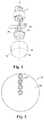
- FIG. 1shows an exploded view of a detection apparatus according to an embodiment of the present application
- FIG. 2shows a particular pattern of an embodiment of a Fresnel lens for the detection apparatus of the present application
- FIG. 3shows another particular pattern of an embodiment of a Fresnel lens for the detection apparatus of the present application
- FIG. 4shows a schematic diagram of the projection of a monitoring scope of the detection apparatus
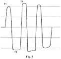
- FIG. 5shows a graph of a voltage signal of the detection apparatus.
- FIG. 1shows a detection apparatus based on a passive infrared sensor according to one embodiment of the present application.
- the detection apparatusmainly comprises: a passive infrared sensor 12 ; a Fresnel lens 13 , arranged on the passive infrared sensor 12 and intended for selectively converging, to the passive infrared sensor 12 , infrared radiation emitted by a detected object for example a human being; and a rotation unit 11 .
- the passive infrared sensor 12 and the Fresnel lens 13can both be directly or indirectly connected to the rotation unit 11 , for example an output shaft 111 of the rotation unit 11 , so that the rotation unit 11 can drive the passive infrared sensor 12 and the Fresnel lens 13 to rotate together.
- the passive infrared sensor 12 and the Fresnel lens 13are arranged coaxially with the output shaft 111 of the rotation unit 11 along an axis A.
- the rotation unit 11can be any apparatus that can drive the passive infrared sensor 12 and the Fresnel lens 13 to rotate; in some embodiments, as shown in the drawings, the rotation unit 11 can comprise a motor, for example a servo motor, and the rotation or stop of or the rotation rate during rotation of the motor can be controlled. In some embodiments, the rotation unit 11 can further comprise a deceleration mechanism connected with the motor, to reduce an output rotation rate of the rotation unit.
- the passive infrared sensor 12 and the Fresnel lens 13can be respectively connected to a base; subsequently, the base comprising the passive infrared sensor 12 and the Fresnel lens 13 can be mounted to the output shaft of the rotation unit 11 , so that the entirety comprising the passive infrared sensor 12 and the Fresnel lens 13 rotates together with the output shaft of the rotation unit 11 .
- the manner of connecting the passive infrared sensor 12 and the Fresnel lens 13 to the rotation unit 11is not limited to the way described in the drawings and above; and any connection mode that can realize the effect that the passive infrared sensor 12 and the Fresnel lens 13 rotate together with the rotation unit 11 can be used.
- the passive infrared sensor 12comprises a single passive infrared sensing unit 121 and a control circuit board 122 connected to the passive infrared sensing unit.
- the passive infrared sensing unit 121is a sensor based on the pyroelectric effect which can generate charges upon a temperature change. The temperature change may be caused by infrared radiation.
- the control circuit board 122is connected with the passive infrared sensing unit 121 , so as to collect a voltage signal caused by the charges generated by the passive infrared sensing unit 121 and realizes the purpose of control based on the voltage signal.
- the Fresnel lens 13comprises an operation region 131 at a lower end and a part 132 at an upper side for enclosing the passive infrared sensor 12 .
- FIG. 2 and FIG. 3show a pattern of an embodiment of the operation region of the Fresnel lens.
- the operation region of the Fresnel lenscomprises at least one radial sensitive zone 21 .
- the operation region 2 of the Fresnel lenscomprises one radial sensitive zone 21 and a blind zone 22 .
- the operation region 3 of the Fresnel lenscomprises four radial sensitive zones 31 , 32 , 33 and 34 .
- the four radial sensitive zones 31 , 32 , 33 and 34are separated by blind zones 35 , 36 , 37 and 38 , and any two adjacent radial sensitive zones form an included angle of 90 degree, so as to form a cross sensitive zone pattern.
- the number of radial sensitive zonescan be adjusted according to practical demands, for example, two, three, five, etc. radial sensitive zones can be selected; and the included angles between various sensitive zones can be adjusted according to practical demands, for example, the included angles can be randomly selected between 0° and 360°. In some embodiments, the included angles can be within the range of 60° to 180°. Furthermore, the included angles between the various adjacent radial sensitive zones can be set to be the same or different.
- the sensitive zones of the Fresnel lensare intended to converge infrared rays within a specific wavelength range irradiated by a detected object onto the sensing unit of the passive infrared sensor.
- the specific wavelength rangecan be 8 to 14 ⁇ m, and the wavelength range covers the infrared radiation wavelengths emitted by human bodies.
- the blind zones of the Fresnel lensare intended for preventing the infrared radiation being converged to the sensing unit of the passive infrared sensor.
- FIG. 4shows a virtual projection of the detection apparatus when the Fresnel lens pattern of FIG. 3 is used.
- the detection apparatuscomprises a rotation unit 11 , and the rotation unit can drive the entirety 40 of the passive infrared sensor and the Fresnel lens to rotate along the direction shown by arrow F or a direction opposite thereto.
- the projected monitoring scope of the detection apparatus onto the groundis denoted by D, and the monitoring scope D comprises a strong sensing zone 41 approximately corresponding to the sensitive zone of the Fresnel lens and a weak sensing zone 42 corresponding to the blind zone of the Fresnel lens.
- the monitoring scope Dincluding the strong sensing zone 41 and the weak sensing zone 42 therein, will also rotate along with the rotation unit 11 of the detection apparatus along the direction indicated by the arrow R or a direction opposite thereto.
- the passive infrared sensing unitwill generate charges and a voltage signal due to the change in the infrared radiation and the pyroelectric effect; and whether a detected object exists in the monitoring scope D can be determined based on the voltage signal.
- the rotation unit 11rotates, the monitoring scope D rotates accordingly; and the detected object, even staying still at A, will also enter the strong sensing zone 41 and the weak sensing zone 42 alternately.
- the infrared radiation emitted by the detected objectis converged to the passive infrared sensing unit, so that the passive infrared sensing unit has an increased temperature and generates charges and generates a voltage signal, for example, a positive voltage; subsequently, when the detected object at A then enters the weak sensing zone 42 from the strong sensing zone 41 , the infrared radiation converged to the passive infrared sensing unit disappears, so that the passive infrared sensing unit has a decreased temperature and generates charges and a voltage signal, for example, a negative voltage.
- the passive infrared sensorcan determine the existence of a detected object upon sensing one or more voltage signals.
- the detection apparatuscan be programmed to improve its sensitivity or accuracy. For example, when a higher sensitivity is needed, it can be programmed to determine the existence of a detected object upon sensing a voltage signal for fewer times, and when a higher accuracy is needed, it can be programmed to determine the existence of a detected object upon sensing a voltage signal for more times.
- the sensitive zonesare radially arranged, the voltage signals received within a certain period of time can be increased or reduced by adjusting the rotation rate of the rotation unit 11 , thus adjusting the sensitivity of the detection apparatus.
- the sensitivity of the detection apparatuscan also be adjusted by adjusting the number of, the included angles between radial sensitive zones, etc.
- the detection functioncan be realized by only enabling the infrared radiation received by the passive infrared sensing unit to change, and for all of the embodiments described above, the sensitive zones and the blind zones of the Fresnel lens can both be arranged oppositely to realize the same or substantially the same effect.
- the rotation unit of the detection apparatuscan rotate intermittently, for example rotating for one or more circles at intervals of A. In some other embodiments, the rotation unit of the detection apparatus can rotate based on the first voltage signal T 1 , that is to say, the detection apparatus starts to rotate after receiving a first voltage signal.
- the detection apparatuscan be applied to a building to realize the purposes of control and security.
- the present applicationalso provides a control system comprising a detection apparatus according to various embodiments of the present application; and the control system can control one or more of lamplight, air conditioner, and heating and/or ventilation system in a building based on information fed back by the detection apparatus.
- the control systemcan also control an alarm system etc. in the building based on the information fed back by the detection apparatus.
Landscapes
- Physics & Mathematics (AREA)
- General Physics & Mathematics (AREA)
- Optics & Photonics (AREA)
- Engineering & Computer Science (AREA)
- Computer Security & Cryptography (AREA)
- Photometry And Measurement Of Optical Pulse Characteristics (AREA)
- Geophysics And Detection Of Objects (AREA)
Abstract
Description
Claims (13)
Applications Claiming Priority (4)
| Application Number | Priority Date | Filing Date | Title |
|---|---|---|---|
| CN201720513048U | 2017-05-10 | ||
| CN201720513048.1UCN206805730U (en) | 2017-05-10 | 2017-05-10 | Detection device and the control system with the detection device |
| CN201720513048.1 | 2017-05-10 | ||
| PCT/US2018/027099WO2018208419A1 (en) | 2017-05-10 | 2018-04-11 | Detecting device and control system with such detecting device |
Publications (2)
| Publication Number | Publication Date |
|---|---|
| US20200202688A1 US20200202688A1 (en) | 2020-06-25 |
| US10891838B2true US10891838B2 (en) | 2021-01-12 |
Family
ID=60739761
Family Applications (1)
| Application Number | Title | Priority Date | Filing Date |
|---|---|---|---|
| US16/612,530ActiveUS10891838B2 (en) | 2017-05-10 | 2018-04-11 | Detecting device and control system with such detecting device |
Country Status (3)
| Country | Link |
|---|---|
| US (1) | US10891838B2 (en) |
| CN (1) | CN206805730U (en) |
| WO (1) | WO2018208419A1 (en) |
Families Citing this family (2)
| Publication number | Priority date | Publication date | Assignee | Title |
|---|---|---|---|---|
| CN108428323A (en)* | 2018-03-08 | 2018-08-21 | 吕梁学院 | A kind of fire detecting arrangement and application method |
| US12158156B2 (en)* | 2022-12-13 | 2024-12-03 | Air Cool Industrial Co., Ltd. | Ceiling fan infrared detection and control system |
Citations (40)
| Publication number | Priority date | Publication date | Assignee | Title |
|---|---|---|---|---|
| US6044632A (en) | 1998-02-05 | 2000-04-04 | Eaton Corporation, Cutler-Hammer Products | Backup proximity sensor for a vehicle |
| US6469625B1 (en)* | 2000-02-18 | 2002-10-22 | Optex Co., Ltd | Security sensor having disturbance detecting capability |
| US6604022B2 (en) | 2001-06-14 | 2003-08-05 | Sharper Image Corporation | Robot for autonomous operation |
| CN200965718Y (en) | 2006-10-18 | 2007-10-24 | 付文军 | Rotary pyroelecteic detector |
| CN200972458Y (en) | 2006-05-10 | 2007-11-07 | 邓斌 | Pyroelectric infrared probe capable of investigating static human body signal |
| CN101285710A (en) | 2008-05-15 | 2008-10-15 | 深圳和而泰智能控制股份有限公司 | Thermal release electric infra-red ray human body detection device |
| CN201149330Y (en) | 2007-12-30 | 2008-11-12 | 海信(山东)空调有限公司 | Air conditioner with sport type infrared sensor |
| US20090014654A1 (en)* | 2005-03-21 | 2009-01-15 | Visonic Ltd. | Passive infra-red detectors |
| CN101866020A (en) | 2010-05-19 | 2010-10-20 | 山东建筑大学 | An intelligent detection device and method for detecting dynamic and static human body |
| EP2259035A1 (en) | 2009-05-29 | 2010-12-08 | BRITISH TELECOMMUNICATIONS public limited company | Heat location sensor |
| CN201707454U (en) | 2010-05-19 | 2011-01-12 | 山东建筑大学 | Intelligent detector for detecting dynamic and static human bodies |
| CN201957306U (en) | 2011-01-25 | 2011-08-31 | 南京信息工程大学 | Classroom energy-saving controller for realizing static detection of human body based on multi-sensor framework |
| CN102183795A (en) | 2011-02-28 | 2011-09-14 | 中北大学 | Target detection system and method based on dynamic utilization of pyroelectric infrared sensor |
| CN201983853U (en) | 2011-01-21 | 2011-09-21 | 赵友杰 | Noise detection and environment purification device |
| CN201983863U (en) | 2011-03-25 | 2011-09-21 | 刘瑜 | Novel infrared human body induction device |
| CN102510640A (en) | 2011-12-14 | 2012-06-20 | 上海工程技术大学 | Self-control switch used for detecting static human body |
| CN102510601A (en) | 2011-10-11 | 2012-06-20 | 天津大学 | Infrared sensing device for detecting static human bodies |
| CN102590884A (en) | 2012-02-15 | 2012-07-18 | 浙江大学 | Human body positioning and following system and method based on pyroelectric infrared sensors |
| CN202818467U (en) | 2012-09-27 | 2013-03-20 | 京东方科技集团股份有限公司 | Energy-saving television |
| CN103135142A (en) | 2011-11-23 | 2013-06-05 | 深圳市富美通科技开发有限公司 | Unmanned detector for guest room |
| CN103197354A (en) | 2013-03-22 | 2013-07-10 | 黄程云 | Digital passive infrared static human body detector and detection method thereof |
| CN203164439U (en) | 2013-03-22 | 2013-08-28 | 黄程云 | Digital passive infrared static human body detector |
| CN103399351A (en) | 2013-07-22 | 2013-11-20 | 深圳市百欧森环保科技开发有限公司 | Oscillating active human body detector for detecting dynamic and static human body and detection method of swing-type active human body detector |
| CN103728028A (en) | 2013-12-31 | 2014-04-16 | 天津大学 | Method for extracting and differentiating human body heat source features of infrared pyroelectricity wavelet packet energy |
| CN103729626A (en) | 2013-12-31 | 2014-04-16 | 天津大学 | Human body heat source feature extracting and distinguishing method based on infrared pyroelectric information |
| CN203734648U (en) | 2014-03-10 | 2014-07-23 | 苏州硕穗光机电科技有限公司 | Rotating-shaft-type human body infrared induction switch |
| US8809788B2 (en) | 2011-10-26 | 2014-08-19 | Redwood Systems, Inc. | Rotating sensor for occupancy detection |
| US8901496B2 (en) | 2012-06-20 | 2014-12-02 | General Electric Company | Overhead occupancy sensor |
| CN203981279U (en) | 2014-08-21 | 2014-12-03 | 衢州迪升工业设计有限公司 | A kind of probe of personal safety monitor device |
| CN104266309A (en) | 2014-09-30 | 2015-01-07 | 章安福 | Method and device for controlling air conditioner to be stopped automatically |
| CN104280134A (en) | 2014-10-16 | 2015-01-14 | 武汉理工大学 | Static human body position estimation device and method based on pyroelectricity technology |
| US8941078B2 (en) | 2006-03-29 | 2015-01-27 | Jansyl Industries, Llc | Infant stimulation and environment sterilizing device |
| CN104422524A (en) | 2013-09-04 | 2015-03-18 | 海尔集团公司 | Human body detection device based on infrared heat source detection |
| CN104697117A (en) | 2015-03-11 | 2015-06-10 | 山东大学 | Energy-saving device and method for air conditioner based on active human body pyroelectric infrared induction |
| CN104698727A (en) | 2015-03-24 | 2015-06-10 | 海信集团有限公司 | Human body protection method and device for laser projection device and laser projection device |
| CN205049760U (en) | 2015-05-19 | 2016-02-24 | 南京信息工程大学 | Infrared detecting device that detectable is static and motion is human |
| US20160320239A1 (en) | 2013-12-11 | 2016-11-03 | Eco Dm Lab Co., Ltd. | Infrared sensor module using rotary ultrasonic motor |
| EP3159709A1 (en) | 2015-10-21 | 2017-04-26 | Everspring Industry Co., Ltd. | Apparatus and method for detecting azimuthal angle of heat source |
| US20190259258A1 (en)* | 2018-02-16 | 2019-08-22 | Optex Co., Ltd. | Security sensor device |
| US20190323897A1 (en)* | 2017-01-13 | 2019-10-24 | The Research Foundation For The State University Of New York | Chopped passive infrared sensor apparatus and method for stationary and moving occupant detection |
- 2017
- 2017-05-10CNCN201720513048.1Upatent/CN206805730U/enactiveActive
- 2018
- 2018-04-11WOPCT/US2018/027099patent/WO2018208419A1/ennot_activeCeased
- 2018-04-11USUS16/612,530patent/US10891838B2/enactiveActive
Patent Citations (49)
| Publication number | Priority date | Publication date | Assignee | Title |
|---|---|---|---|---|
| US6044632A (en) | 1998-02-05 | 2000-04-04 | Eaton Corporation, Cutler-Hammer Products | Backup proximity sensor for a vehicle |
| US6469625B1 (en)* | 2000-02-18 | 2002-10-22 | Optex Co., Ltd | Security sensor having disturbance detecting capability |
| US6604022B2 (en) | 2001-06-14 | 2003-08-05 | Sharper Image Corporation | Robot for autonomous operation |
| US20090014654A1 (en)* | 2005-03-21 | 2009-01-15 | Visonic Ltd. | Passive infra-red detectors |
| US8941078B2 (en) | 2006-03-29 | 2015-01-27 | Jansyl Industries, Llc | Infant stimulation and environment sterilizing device |
| CN200972458Y (en) | 2006-05-10 | 2007-11-07 | 邓斌 | Pyroelectric infrared probe capable of investigating static human body signal |
| CN200965718Y (en) | 2006-10-18 | 2007-10-24 | 付文军 | Rotary pyroelecteic detector |
| CN201149330Y (en) | 2007-12-30 | 2008-11-12 | 海信(山东)空调有限公司 | Air conditioner with sport type infrared sensor |
| CN101285710A (en) | 2008-05-15 | 2008-10-15 | 深圳和而泰智能控制股份有限公司 | Thermal release electric infra-red ray human body detection device |
| CN101285710B (en) | 2008-05-15 | 2010-12-22 | 深圳和而泰智能控制股份有限公司 | Thermal release electric infra-red ray human body detection device |
| EP2259035A1 (en) | 2009-05-29 | 2010-12-08 | BRITISH TELECOMMUNICATIONS public limited company | Heat location sensor |
| CN201707454U (en) | 2010-05-19 | 2011-01-12 | 山东建筑大学 | Intelligent detector for detecting dynamic and static human bodies |
| CN101866020A (en) | 2010-05-19 | 2010-10-20 | 山东建筑大学 | An intelligent detection device and method for detecting dynamic and static human body |
| CN101866020B (en) | 2010-05-19 | 2012-09-05 | 山东建筑大学 | Intelligent detection method for detecting dynamic and static human body |
| CN201983853U (en) | 2011-01-21 | 2011-09-21 | 赵友杰 | Noise detection and environment purification device |
| CN201957306U (en) | 2011-01-25 | 2011-08-31 | 南京信息工程大学 | Classroom energy-saving controller for realizing static detection of human body based on multi-sensor framework |
| CN102183795B (en) | 2011-02-28 | 2013-12-25 | 中北大学 | Target detection system and method based on dynamic utilization of pyroelectric infrared sensor |
| CN102183795A (en) | 2011-02-28 | 2011-09-14 | 中北大学 | Target detection system and method based on dynamic utilization of pyroelectric infrared sensor |
| CN201983863U (en) | 2011-03-25 | 2011-09-21 | 刘瑜 | Novel infrared human body induction device |
| CN102510601B (en) | 2011-10-11 | 2014-04-02 | 天津大学 | Infrared sensing device for detecting static human bodies |
| CN102510601A (en) | 2011-10-11 | 2012-06-20 | 天津大学 | Infrared sensing device for detecting static human bodies |
| US8809788B2 (en) | 2011-10-26 | 2014-08-19 | Redwood Systems, Inc. | Rotating sensor for occupancy detection |
| CN103135142A (en) | 2011-11-23 | 2013-06-05 | 深圳市富美通科技开发有限公司 | Unmanned detector for guest room |
| CN102510640B (en) | 2011-12-14 | 2014-02-05 | 上海工程技术大学 | Self-control switch used for detecting static human body |
| CN102510640A (en) | 2011-12-14 | 2012-06-20 | 上海工程技术大学 | Self-control switch used for detecting static human body |
| CN102590884B (en) | 2012-02-15 | 2013-11-13 | 浙江大学 | Human body positioning and following system and method based on pyroelectric infrared sensors |
| CN102590884A (en) | 2012-02-15 | 2012-07-18 | 浙江大学 | Human body positioning and following system and method based on pyroelectric infrared sensors |
| US8901496B2 (en) | 2012-06-20 | 2014-12-02 | General Electric Company | Overhead occupancy sensor |
| CN202818467U (en) | 2012-09-27 | 2013-03-20 | 京东方科技集团股份有限公司 | Energy-saving television |
| CN203164439U (en) | 2013-03-22 | 2013-08-28 | 黄程云 | Digital passive infrared static human body detector |
| CN103197354A (en) | 2013-03-22 | 2013-07-10 | 黄程云 | Digital passive infrared static human body detector and detection method thereof |
| CN103197354B (en) | 2013-03-22 | 2015-08-12 | 黄程云 | Digital passive infrared human body detector and detection method thereof |
| CN103399351A (en) | 2013-07-22 | 2013-11-20 | 深圳市百欧森环保科技开发有限公司 | Oscillating active human body detector for detecting dynamic and static human body and detection method of swing-type active human body detector |
| CN103399351B (en) | 2013-07-22 | 2016-08-10 | 深圳市百欧森环保科技开发有限公司 | Swing type active detecting people's body device of detection dynamic and static human body and detection method thereof |
| CN104422524A (en) | 2013-09-04 | 2015-03-18 | 海尔集团公司 | Human body detection device based on infrared heat source detection |
| US20160320239A1 (en) | 2013-12-11 | 2016-11-03 | Eco Dm Lab Co., Ltd. | Infrared sensor module using rotary ultrasonic motor |
| CN103728028A (en) | 2013-12-31 | 2014-04-16 | 天津大学 | Method for extracting and differentiating human body heat source features of infrared pyroelectricity wavelet packet energy |
| CN103729626A (en) | 2013-12-31 | 2014-04-16 | 天津大学 | Human body heat source feature extracting and distinguishing method based on infrared pyroelectric information |
| CN203734648U (en) | 2014-03-10 | 2014-07-23 | 苏州硕穗光机电科技有限公司 | Rotating-shaft-type human body infrared induction switch |
| CN203981279U (en) | 2014-08-21 | 2014-12-03 | 衢州迪升工业设计有限公司 | A kind of probe of personal safety monitor device |
| CN104266309A (en) | 2014-09-30 | 2015-01-07 | 章安福 | Method and device for controlling air conditioner to be stopped automatically |
| CN104280134A (en) | 2014-10-16 | 2015-01-14 | 武汉理工大学 | Static human body position estimation device and method based on pyroelectricity technology |
| CN104697117A (en) | 2015-03-11 | 2015-06-10 | 山东大学 | Energy-saving device and method for air conditioner based on active human body pyroelectric infrared induction |
| CN104698727A (en) | 2015-03-24 | 2015-06-10 | 海信集团有限公司 | Human body protection method and device for laser projection device and laser projection device |
| CN104698727B (en) | 2015-03-24 | 2017-01-11 | 海信集团有限公司 | Human body protection method and device for laser projection device and laser projection device |
| CN205049760U (en) | 2015-05-19 | 2016-02-24 | 南京信息工程大学 | Infrared detecting device that detectable is static and motion is human |
| EP3159709A1 (en) | 2015-10-21 | 2017-04-26 | Everspring Industry Co., Ltd. | Apparatus and method for detecting azimuthal angle of heat source |
| US20190323897A1 (en)* | 2017-01-13 | 2019-10-24 | The Research Foundation For The State University Of New York | Chopped passive infrared sensor apparatus and method for stationary and moving occupant detection |
| US20190259258A1 (en)* | 2018-02-16 | 2019-08-22 | Optex Co., Ltd. | Security sensor device |
Non-Patent Citations (3)
| Title |
|---|
| Deshmukh, Abhisek et al., "Improvised-PIR Sensor for Stationery and Motional Human Detection", International J. of Advanced Research in Electrical, Electronics and Instrumentation Engineering, vol. 4, Issue 10, Oct. 2015, 5 pages. |
| International Search Report and Written Opinion for application PCT/ US2018/027099, dated Jul. 20, 2018, 12 pages. |
| Sun, Qingquan et al., "Static Human Detection and Scenario Recognition via Wearable Thermal Sensing System", MDPI Computers, published Jan. 20, 2017, 11 pages. |
Also Published As
| Publication number | Publication date |
|---|---|
| CN206805730U (en) | 2017-12-26 |
| WO2018208419A1 (en) | 2018-11-15 |
| US20200202688A1 (en) | 2020-06-25 |
Similar Documents
| Publication | Publication Date | Title |
|---|---|---|
| US8314390B2 (en) | PIR motion sensor system | |
| SE441551B (en) | PASSIVE INFRAROAD INFRASTRUCTURE DETECTION DEVICE | |
| CN104422524B (en) | A kind of apparatus for detecting human body based on infrared heat source detection | |
| US10891838B2 (en) | Detecting device and control system with such detecting device | |
| EP2957149A1 (en) | Motion detector system, lighting system with such system and method for detecting moving vehicles and/or pedestrians | |
| US20160320239A1 (en) | Infrared sensor module using rotary ultrasonic motor | |
| JP5761557B2 (en) | Pyroelectric infrared sensor device, detection method and program | |
| JPH02183752A (en) | Infrared detection device for air conditioners | |
| JP6279407B2 (en) | Human body detection device | |
| WO2020000186A1 (en) | Pyroelectric infrared detection system | |
| TWI558988B (en) | Apparatus and method for detecting azimuth of heat source | |
| WO2022008340A1 (en) | Systems and methods for people counting using beam-forming passive infrared sensors having a dynamically configurable field of view | |
| CN211116743U (en) | A moving head home appliance controller based on multiple pyroelectric infrared sensors | |
| US12442690B2 (en) | Systems and methods for people counting using beam-forming passive infrared sensors having a dynamically configurable field of view | |
| JP7281671B2 (en) | Compound eye type human body detection device | |
| KR101703226B1 (en) | Non-contact type temperature and motion detection apparatus and method therefor | |
| JP2008190923A (en) | Heat ray sensor | |
| CN119756595B (en) | Pyroelectric lens system and detection method of target detection object | |
| US20190043324A1 (en) | A volumetric occupancy counting system | |
| KR20150005313A (en) | Infra-red Laser Device for inspection | |
| JP2000283839A (en) | Infrared human body detector | |
| JP2000234957A (en) | Moving object-detecting device | |
| Mathas | Sensing motion with passive infrared (PIR) sensors | |
| JP6785072B2 (en) | Infrared source detection system and infrared source detection method | |
| JPH06242255A (en) | Human body detector |
Legal Events
| Date | Code | Title | Description |
|---|---|---|---|
| AS | Assignment | Owner name:CARRIER AIR CONDITIONING AND REFRIGERATION R&D MANAGEMENT (SHANGHAI) CO., LTD., CHINA Free format text:ASSIGNMENT OF ASSIGNORS INTEREST;ASSIGNOR:TIAN, LINGHAO;REEL/FRAME:050974/0700 Effective date:20170601 Owner name:CARRIER CORPORATION, FLORIDA Free format text:ASSIGNMENT OF ASSIGNORS INTEREST;ASSIGNOR:CARRIER AIR CONDITIONING AND REFRIGERATION R&D MANAGEMENT (SHANGHAI) CO., LTD.;REEL/FRAME:050974/0710 Effective date:20170830 | |
| FEPP | Fee payment procedure | Free format text:ENTITY STATUS SET TO UNDISCOUNTED (ORIGINAL EVENT CODE: BIG.); ENTITY STATUS OF PATENT OWNER: LARGE ENTITY | |
| STPP | Information on status: patent application and granting procedure in general | Free format text:RESPONSE TO NON-FINAL OFFICE ACTION ENTERED AND FORWARDED TO EXAMINER | |
| STPP | Information on status: patent application and granting procedure in general | Free format text:PUBLICATIONS -- ISSUE FEE PAYMENT VERIFIED | |
| STCF | Information on status: patent grant | Free format text:PATENTED CASE | |
| MAFP | Maintenance fee payment | Free format text:PAYMENT OF MAINTENANCE FEE, 4TH YEAR, LARGE ENTITY (ORIGINAL EVENT CODE: M1551); ENTITY STATUS OF PATENT OWNER: LARGE ENTITY Year of fee payment:4 |