US10890955B2 - System for controlling environmental conditions within an automated data storage library - Google Patents
System for controlling environmental conditions within an automated data storage libraryDownload PDFInfo
- Publication number
- US10890955B2 US10890955B2US15/460,429US201715460429AUS10890955B2US 10890955 B2US10890955 B2US 10890955B2US 201715460429 AUS201715460429 AUS 201715460429AUS 10890955 B2US10890955 B2US 10890955B2
- Authority
- US
- United States
- Prior art keywords
- enclosure
- data storage
- library
- environmental
- storage library
- Prior art date
- Legal status (The legal status is an assumption and is not a legal conclusion. Google has not performed a legal analysis and makes no representation as to the accuracy of the status listed.)
- Active, expires
Links
Images


Classifications
- G—PHYSICS
- G06—COMPUTING OR CALCULATING; COUNTING
- G06F—ELECTRIC DIGITAL DATA PROCESSING
- G06F1/00—Details not covered by groups G06F3/00 - G06F13/00 and G06F21/00
- G06F1/16—Constructional details or arrangements
- G06F1/20—Cooling means
- G06F1/206—Cooling means comprising thermal management
- H—ELECTRICITY
- H05—ELECTRIC TECHNIQUES NOT OTHERWISE PROVIDED FOR
- H05K—PRINTED CIRCUITS; CASINGS OR CONSTRUCTIONAL DETAILS OF ELECTRIC APPARATUS; MANUFACTURE OF ASSEMBLAGES OF ELECTRICAL COMPONENTS
- H05K7/00—Constructional details common to different types of electric apparatus
- H05K7/20—Modifications to facilitate cooling, ventilating, or heating
- H05K7/20709—Modifications to facilitate cooling, ventilating, or heating for server racks or cabinets; for data centers, e.g. 19-inch computer racks
- H05K7/20836—Thermal management, e.g. server temperature control
- G—PHYSICS
- G05—CONTROLLING; REGULATING
- G05B—CONTROL OR REGULATING SYSTEMS IN GENERAL; FUNCTIONAL ELEMENTS OF SUCH SYSTEMS; MONITORING OR TESTING ARRANGEMENTS FOR SUCH SYSTEMS OR ELEMENTS
- G05B2219/00—Program-control systems
- G05B2219/20—Pc systems
- G05B2219/21—Pc I-O input output
- G05B2219/21156—Over temperature protection
Definitions
- the present disclosurerelates to a data storage library for the storage and data transfer of data storage media, and more specifically, to a system for controlling the environmental conditions within a data storage library.
- Automated data storage librariesare known for providing cost effective storage and retrieval of large quantities of data.
- the data in automated data storage librariesis typically stored on media of data storage cartridges that are, in turn, stored at storage slots or the like inside the library in a fashion that renders the media, and its resident data, accessible for physical retrieval.
- Such data storage cartridgesare commonly termed “removable media.”
- Data storage cartridge mediamay comprise any type of media on which data may be stored and which may serve as removable media, including but not limited to magnetic media (such as magnetic tape or disks), optical media (such as optical tape or disks), electronic media (such as PROM, EEPROM, flash PROM, COMPACTFLASHTM, SMARTMEDIATM, MEMORY STICKTM, etc.), or other suitable media.
- An example of a data storage cartridge that is widely employed in automated data storage libraries for mass data storageis a magnetic tape cartridge.
- automated data storage librariestypically comprise data storage drives that store data to, and/or retrieve data from, the data storage cartridge media.
- automated data storage librariestypically comprise I/O stations at which data storage cartridges are supplied or added to, or removed from, the library.
- the transport of data storage cartridges between data storage slots, data storage drives, and I/O stationsis typically accomplished by one or more robotic accessors.
- Such accessorshave grippers for physically retrieving the selected data storage cartridges from the storage slots within the automated data storage library and transporting such cartridges to the data storage drives by moving, for example, in the horizontal (X) and vertical (Y) directions.
- deep slot technologyallows for storage cells that contain more than a single data storage cartridge.
- Such storage librariesallow for higher density, or more cartridges stored per square foot.
- two or more cartridgesmay be stored in a multi-cartridge deep slot cell, arrayed in series, one behind the other, in tiers ranging from a front-most tier to a rearmost tier.
- Efforts to improve the performance of traditional data centersattempt to minimize the cost of processing and storing data.
- One option that is employed to reduce operational costs of datacentersis to run the equipment in the datacenter at the high end of its environmental operational limits, thereby allowing for cooling of the datacenter to be reduced.
- datacentersare running increasingly hot and more humid conditions than traditional datacenters in an attempt to reduce operating costs.
- this strategymay be effective when applied to disk and/or flash data storage environments, magnetic tape is more susceptible to degradation when exposed to these unfavorable conditions. Therefore, this option is not available for magnetic tape libraries.
- environmental conditioning unitsmay be incorporated into (or on) the data storage libraries themselves.
- some data storage librariesmay be too small to incorporate an integrated environmental conditioning unit and/or may not be large enough to justify an integrated environmental conditioning unit.
- incorporation of an environmental conditioning unitalso may involve significant engineering and/or alterations to the data storage library in order to properly mount the environmental conditioning unit, substantially seal the data storage library, drain condensation produced by the environmental conditioning unit, etc.
- a system for controlling at least one environmental condition within a data storage libraryincludes a data storage library and at least one enclosure surrounding at least a portion of the data storage library.
- the systemalso includes at least one environmental conditioning unit fluidly connected to the at least one enclosure via at least one duct, wherein the at least one environmental conditioning unit is configurable to control at least one environmental condition within the at least one enclosure and within the data storage library.
- the at least one enclosuremay be formed of at least one flexible material, the at least one flexible material selected from the group consisting of nylon, polyester, canvas, cotton, silk, plastic, foil, para-aramid synthetic fiber, and combinations thereof.
- the at least one enclosuremay be formed of at least one rigid material, the at least one rigid material selected from the group consisting of wood, plastic, carbon fiber, metal, and combinations thereof.
- the at least one enclosurefurther may include at least one access opening to permit access to the interior of the at least one enclosure.
- the at least one access openingmay have an access door to impede intrusion of exterior environmental conditions and escape of interior environmental conditions.
- the at least one enclosuremay enclose the entire data storage library. Alternatively, the at least one enclosure may enclose only one side of the library which includes the at least one access opening of the data storage library.
- a deviceincluding an enclosure configured to at least partially surround at least a portion of a data storage library.
- the enclosuremay include at least one surface configured to surround the at least one opening in the data storage library, and at least one enclosure access door in the at least one of the surface of sufficient size to permit access to at least a portion of the data storage library.
- the enclosuremay also include at least one duct connection configured to fluidly connect at least one duct from an environmental conditioning unit to the enclosure.
- the enclosuremay be formed of at least one flexible material, the at least one flexible material selected from the group consisting of nylon, polyester, canvas, cotton, silk, plastic, foil, para-aramid synthetic fiber, and combinations thereof. Additionally, the enclosure may further include a collapsible frame structure. Alternatively, the enclosure may be formed of at least one rigid material selected from the group consisting of wood, plastic, carbon fiber, metal, and combinations thereof.
- the enclosuremay further include at least one environmental sensor for measuring at least one of temperature, humidity, and combinations thereof.
- the at least one enclosure access doormay comprise at least one of a hinged door, split membrane, sliding panel, rolled door, hinged flap, a zippered door, vertically-hanging slats, an air curtain, and vertically-hanging flaps.
- a systemwhich includes at least one data storage library having at least one ventilation opening therein, and at least one enclosure configurable to surround the data storage library, the at least one enclosure configured to form a chamber of sufficient size to contain the data storage library.
- the systemalso includes at least one environmental conditioning unit fluidly connected to the at least one enclosure, wherein the at least one environmental conditioning unit is configured to control one or more environmental conditions within the data storage library.
- the at least one environmental conditioning unitmay be fluidly connected to the at least one enclosure by at least one supply duct.
- the systemmay include a plurality of data storage libraries respectively surrounded by a plurality of enclosures, wherein a single environmental conditioning unit is configured to be fluidly connected to the plurality of enclosures.
- At least one of a Y-duct and a manifoldmay fluidly connect the single environmental conditioning unit to the plurality of enclosures.
- a system for controlling at least one environmental condition within at least one data storage librarymay include a data storage library, wherein the data storage library comprises a housing having at least a first ventilation opening in a first surface thereon.
- the systemmay also include a first enclosure configured to surround at least the first ventilation opening on the first surface of the data storage library, as well as at least one environmental conditioning unit configured to control at least one environmental condition within the data storage library, wherein the at least one environmental conditioning unit is fluidly connected to the first enclosure by at least one supply duct.
- the housingmay further include at least a second ventilation opening in a second surface thereon, and the system may include a second enclosure configured to surround at least the second ventilation opening in the second surface of the data storage library, wherein the at least one environmental conditioning unit is fluidly connected to the second enclosure by at least one return duct. Additionally, the first enclosure may be configured to surround only the first ventilation opening and the second enclosure may be configured to surround only the second ventilation opening.
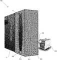
- FIG. 1is a perspective view of an automated data storage library according to one embodiment.
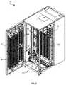
- FIG. 2is a perspective view of the interior of a storage frame from the data storage library of FIG. 1 .
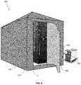
- FIG. 3is a perspective view of an automated data storage library according to another embodiment.
- FIG. 4is a schematic diagram of an automated data storage library according to one embodiment.
- FIG. 5is a block diagram depicting a controller configuration according to one embodiment.
- FIG. 6is a perspective view of an environmental conditioning system for a data storage library in accordance with one aspect.
- FIG. 7is a perspective view of an environmental conditioning system for a data storage library in accordance with another aspect.
- FIG. 8is a perspective view of an environmental conditioning system for a data storage library in accordance with another aspect.
- FIG. 9is a perspective view of an environmental conditioning system for a data storage library in accordance with another aspect.
- FIG. 10Ais a front view of an environmental conditioning system for a data storage library in accordance with another aspect.
- FIG. 10Bis a rear view of an environmental conditioning system for the data storage library of FIG. 10A .
- FIG. 11Ais a side view of a Y-duct in accordance with one aspect.
- FIG. 11Bis a side view of a multi-port manifold in accordance with another aspect.
- FIG. 12is a perspective view of an environmental conditioning system for a plurality if data storage libraries in accordance with another aspect.
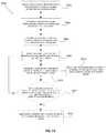
- FIG. 13is a flowchart of a method of providing environmentally controlled air into a data storage library in accordance with one aspect.
- FIG. 14is a flowchart of a method of providing environmentally controlled air into a data storage library in accordance with another aspect.
- FIG. 15a flowchart of a method of providing environmentally controlled air into a data storage library in accordance with another aspect.
- FIGS. 1-3illustrate an example of a data storage system, e.g., an automated data storage library 10 which stores and retrieves data storage cartridges, containing data storage media (not shown), from multi-cartridge deep slot storage cells 100 and single cartridge storage slots 16 .
- Examples of an automated data storage librarywhich has a similar configuration as that depicted in FIGS. 1-3 , and may be implemented with some of the various approaches herein may include IBM TS4500 Library or the IBM 3584 UltraScalable Tape Library.
- the library 10may comprise a single frame 11 (as shown in FIGS. 1-2 ) or multiple frames (as shown in FIG. 3 ).
- the library 10 in the embodiment of FIG. 3comprises a left hand service bay 13 , one or more storage frames 11 , and right hand service bay 14 .
- a framemay comprise an expansion component of the library.
- storage framesmay be added or removed to expand or reduce the size and/or functionality of the library.
- framesmay include additional storage slots, deep storage slot cells, drives, import/export stations, accessors, operator panels, controller cards, communication cards, power supplies, etc.
- an accessor aisle 12preferably extends between the storage frames and bays of the embodiment in FIG. 3 , thereby allowing an accessor to move between frames.
- FIGS. 1-2show an exemplary embodiment of a storage frame 11 , which may act as the base frame of the library 10 .
- the storage frame 11 illustrated in FIG. 2may have only a single accessor 18 (i.e., there are no redundant accessors) and no service bay.
- a storage framemay include multiple robotic accessors and/or service bays.
- the library 10is arranged for accessing data storage media in response to commands from at least one external host system (not shown).
- the library 10includes a plurality of storage slots 16 on front door 17 and a plurality of multi-cartridge deep slot cells 100 on rear wall 19 , both of which may be used for storing data storage cartridges that may contain data storage media.
- the storage slots 16are configured to store a single data storage cartridge
- the multi-cartridge deep slot cells 100are configured to store a plurality of data storage cartridges.
- the arrangement and positioning of the storage slots 16 and the deep slot cells 100may be different than illustrated in FIG. 2 .
- the storage frame 11 of the library 10also includes at least one data storage drive 15 , e.g., for reading and/or writing data with respect to the data storage media in the data storage cartridges.
- a first accessor 18may be used to transport data storage cartridges containing data storage media between the plurality of storage slots 16 , the multi-cartridge deep slot cells 100 , and/or the data storage drive(s) 15 .
- the data storage drives 15may be optical disk drives, magnetic tape drives, or other types of data storage drives that are used to read and/or write data with respect to the data storage media.
- the storage frame 11may optionally include an operator panel or other user interface, such as a web-based interface, which allows a user to interact with the library 10 .
- the library 10may have an associated software application having a user interface, which also allows a user to interact with the library 10 .
- the software applicationmay be executable on a computing device, a remote server, a cloud or a mobile device.
- the automated data storage library 10as described in reference to FIGS. 1-3 , is depicted according to one embodiment.
- the library 10may employ a controller, e.g., arranged as a distributed system of modules with a plurality of processor nodes.
- the libraryis controlled, not by a central controller, but rather, by a distributed control system for receiving logical commands and converting the commands to physical movements of the accessor and gripper, and for operating the drives in accordance with the desired physical movements.
- the distributed control systemmay also provide logistical support, such as responding to host requests for element status, inventory, library status, etc.
- the specific commands, the conversion of those commands to physical movements of the accessor, gripper, controllers, and other components, and the operation of the drivesmay be of a type known to those of skill in the art.
- automated data storage library 10has been described as employing a distributed control system, various other approaches described and/or suggested herein may be implemented in automated data storage libraries regardless of control configuration, such as, but not limited to, an automated data storage library having one or more library controllers that are not distributed.
- library 10receives commands from one or more host systems 40 , 41 , 42 .
- the host systems 40 , 41 , 42such as host servers, communicate with the library directly, e.g., on line 80 (e.g., path), through one or more control ports (not shown), or through one or more data storage drives 15 on paths 81 , 82 .
- the host systems 40 , 41 , 42may provide commands to access particular data storage cartridges and move the cartridges, for example, between the storage slots 16 , the deep slot cells 100 , and the data storage drives 15 .
- the commandsare typically logical commands identifying the data storage cartridges or data storage cartridge media, and/or logical locations for accessing the media.
- commandsand “work requests” are used interchangeably herein to refer to such communications from the host system 40 , 41 , 42 to the library 10 as are intended to result in accessing particular data storage media within the library 10 depending on the desired approach.
- the library 10may be controlled by a library controller.
- the library controllermay include a distributed control system receiving the logical commands from hosts, determining the required actions, and/or converting the actions to physical movements of the first and/or second accessors 18 , 28 and/or gripper assemblies 20 , 30 .
- the distributed control systemmay have a plurality of processor nodes, each having one or more computer processors.
- a communication processor node 50may be located in a storage frame 11 . The communication processor node provides a communication link for receiving the host commands, either directly or through the drives 15 , via at least one external interface, e.g., coupled to line 80 .
- the communication processor node 50is coupled to each of the data storage drives 15 of a storage frame 11 , via lines 70 , and may communicate with the drives 15 and with host systems 40 , 41 , 42 .
- the host systems 40 , 41 , 42may be directly coupled to the communication processor node 50 , at line 80 (e.g., input) for example, or to control port devices (not shown) which connect the library to the host system(s) with a library interface similar to the drive/library interface.
- line 80e.g., input
- control port devicesnot shown
- various communication arrangementsmay be employed for communication with the hosts and with the data storage drives. In the example of FIG.
- lines 80 and 81are intended to be Ethernet and a SCSI bus, respectively, and may serve as host connections.
- path 82comprises an example of a Fibre Channel bus which is a high speed serial data interface, allowing transmission over greater distances than the SCSI bus systems.
- the data storage drives 15may be in close proximity to the communication processor node 50 , and may employ a short distance communication scheme, such as Ethernet, or a serial connection, such as RS-422. Thus, the data storage drives 15 may be individually coupled to the communication processor node 50 by lines 70 . Alternatively, the data storage drives 15 may be coupled to the communication processor node 50 through one or more networks.
- additional storage frames 11may be provided, whereby each is preferably coupled to the adjacent storage frame.
- any of the additional storage frames 11may include communication processor nodes 50 , storage slots 16 , storage cells 100 , data storage drives 15 , networks 60 , etc.
- An automated data storage library 10typically comprises one or more controllers to direct the operation of the automated data storage library. Moreover, host computers and data storage drives typically include similar controllers.
- a library controllermay take many different forms and may comprise, for example, but is not limited to, an embedded system, a distributed control system, a personal computer, a workstation, etc.
- the term “library controller” as used hereinis intended in its broadest sense as a device that includes at least one processor, and optionally further circuitry and/or logic, for controlling and/or providing at least some aspects of library operations.
- a typical controller 400is shown with a processor 402 , Random Access Memory (RAM) 403 , nonvolatile memory 404 , device specific circuits 401 , and I/O interface 405 .
- the RAM 403 and/or nonvolatile memory 404may be contained in the processor 402 as could the device specific circuits 401 and I/O interface 405 .
- the processor 402may comprise, for example, an off-the-shelf microprocessor, custom processor, Field Programmable Gate Array (FPGA), Application Specific Integrated Circuit (ASIC), discrete logic, etc.
- the RAM 403is typically used to hold variable data, stack data, executable instructions, etc.
- the nonvolatile memory 404may comprise any type of nonvolatile memory such as, but not limited to, Electrically Erasable Programmable Read Only Memory (EEPROM), flash Programmable Read Only Memory (PROM), battery backup RAM, hard disk drives, etc.
- EEPROMElectrically Erasable Programmable Read Only Memory
- PROMflash Programmable Read Only Memory
- the nonvolatile memory 404is typically used to hold the executable firmware and any nonvolatile data containing programming instructions that can be executed to cause the processor 402 to perform certain functions.
- the I/O interface 405may include a communication interface that allows the processor 402 to communicate with devices external to the controller.
- Examples of the communication interfacemay comprise, but are not limited to, serial interfaces such as RS-232, USB (Universal Serial Bus), Small Computer Systems Interface (SCSI), RS-422 or a wireless communication interface such as Wi-Fi, Bluetooth, near-field communication (NFC) or other wireless interfaces.
- the controller 400may communicate with an external device via the communication interface 405 in any communication protocols such as Automation/Drive Interface (ADI).
- ADIAutomation/Drive Interface
- the device specific circuits 401provide additional hardware to enable the controller 400 to perform unique functions including, but not limited to, motor control of an accessor cartridge gripper. Moreover, the device specific circuits 401 may include electronics that provide, by way of example but not limitation, Pulse Width Modulation (PWM) control, Analog to Digital Conversion (ADC), Digital to Analog Conversion (DAC), etc. In addition, all or part of the device specific circuits 401 may reside outside the controller 400 .
- PWMPulse Width Modulation
- ADCAnalog to Digital Conversion
- DACDigital to Analog Conversion
- a library controllermay comprise one or more dedicated controllers of a library, depending on the desired embodiment. For example, there may be a primary controller and a backup controller.
- a library controllermay comprise one or more processor nodes of a distributed control system.
- communication processor node 50e.g., of FIG. 4
- the other processor nodesif present may assist the library controller and/or may provide backup or redundant functionality.
- communication processor node 50 and work processor node 52may work cooperatively to form the library controller while the other processor nodes (if present) may assist the library controller and/or may provide backup or redundant functionality. Still further, all of the processor nodes may comprise the library controller. According to various approaches described and/or suggested herein, a library controller may have a single processor or controller, or it may include multiple processors or controllers, or multiple cores in a processor chip.
- an apparatusfor example an enclosure
- the enclosuremay be fluidly connected to an associated environmental conditioning unit (e.g., an air conditioning unit), which may deliver conditioned air into the enclosure and, by extension, into the data storage library.
- an environmental conditioning unite.g., an air conditioning unit
- the environmental conditions within the interior of the data storage librarymay be controlled without the need for an integrated environmental conditioning unit attached thereto.
- Environmental conditioning system 500comprises an enclosure 502 configured to substantially surround a data storage library frame 11 , similar to that described above with respect to FIGS. 1-2 . While FIG. 6 only shows library frame 11 comprising a single library frame, it is to be understood that a plurality of library frames, such as that which is illustrated in FIG. 3 , may be at least partially surrounded by enclosure 502 .
- Library frame(s) 11may comprise conventional data storage library components, similar to that which is found in library 10 described above with respect to FIG. 2 .
- one or more of library frames 11may comprise a plurality of storage slots to hold data storage cartridges associated with data storage media, one or more data storage drives to read and/or write data associated with the media associated with the data storage cartridges, and one or more robotic accessors.
- enclosure 502may have a tent-like structure, with the capability of being easily and quickly erected and/or installed (and/or uninstalled and/or disassembled) to substantially surround one or more library frames 11 .
- the walls of enclosure 502may be self-supporting, or may be held by a collapsible and/or removable framework structure (not shown).
- the framework structuremay be formed of any appropriate material, such as, for example, a plurality of fiberglass or para-aramid synthetic fiber (e.g., KEVLAR®) poles.
- the framework structuremay be broken down and/or collapsed so as to enable the enclosure 502 to be portable and storable when not in use.
- the framework structuremay comprise a plurality of spring-biased joints and/or flexible structures, enabling the structure to partially or fully automatically erect when opened or released. While shown surrounding library frame(s) 11 in FIG. 6 , it is to be understood that enclosure 502 may be erected alone and may not require the presence of one or more library frames 11 in order to maintain shape and form. Alternatively, enclosure 502 may use elements of frames 11 for support or attachment points.
- Enclosure 502may be formed of any suitable material, such as nylon, polyester, canvas, cotton, silk, plastic, foil, a para-aramid synthetic fiber (e.g., KEVLAR®), or any other flexible material.
- the materialpreferably provides a barrier to environmental conditions.
- the enclosureresists, inhibits, and/or prevents environmental conditions outside the enclosure from intruding and/or infiltrating into the interior chamber formed by the enclosure.
- the enclosure 502in one embodiment may provide and/or maintain substantially stable environmental conditions within the enclosure 502 .
- enclosure 502may comprise multiple layers of multiple materials, either alike or different, so as to provide varying degrees of insulating properties, if needed.
- One or more layers of material of enclosure 502may be an insulation layer.
- at least a portion of enclosure 502may be formed of a substantially water-resistant or waterproof material.
- At least one closable access door 504may be provided on at least one side wall of enclosure 502 so as to allow access by an operator into the interior chamber formed by enclosure 502 .
- Access door 504may be made of the any suitable material or combination of materials, and they may be the same or different materials than enclosure 502 , such as, for example, nylon, polyester, canvas, cotton, silk, plastic, foil, a para-aramid synthetic fiber (e.g., KEVLAR®), or any other flexible material.
- the access door 504may be selectively openable and closable. When open, access door 504 provides an opening preferably of sufficient size to permit a technician (human adult) access to the interior chamber of the enclosure 502 .
- access door 504may be configured as a hinged flap, a zippered door, one or more vertically-hanging slats or flaps, an air curtain, or any other appropriate closure capable of allowing selective access, yet allowing closure in order to provide a barrier between the environment within enclosure 502 and the environment outside the enclosure 502 .
- enclosure 502When access door 504 is closed, enclosure 502 may form a chamber having environmental conditions around library frame(s) 11 that may be substantially separate from and different than the environmental conditions outside the enclosure 502 .
- An environmental conditioning unit 506located outside of and separate from enclosure 502 , may be fluidly connected to the enclosure 502 via at least one duct 508 .
- ductmay refer to any material, apparatus or structure that allows air to be moved from one location to another.
- the environmental conditioning unit 506may operate to provide conditioned air into the interior of the enclosure 502 , thereby controlling at least one environmental condition (e.g., temperature and/or humidity) within the enclosure 502 .
- the environmental conditioning unit 506may be any suitable mechanism to condition the air, which may comprise cooling, heating, removing humidity, adding humidity, filtering, or any other modification to the ambient air.
- one or more environmental sensors 510may be located within enclosure 502 such that the controller of the environmental conditioning unit 506 (or another control system, such as library controller 400 ) may maintain one or more set environmental conditions within enclosure 502 .
- the environmental sensor(s) 510may be, for example, temperature and/or humidity sensors.
- library frame(s) 11may also incorporate one or more environmental sensors therein for the same purpose as that described above.
- the environmental sensor(s) 510may communicate with the environmental conditioning unit 506 or other controller via any suitable connection means, such as a wired connection or wireless connection.
- any suitable connection meanssuch as a wired connection or wireless connection.
- environmental sensor(s) 510may be provided at any suitable location(s) within enclosure 502 (which may also comprise a location within frame 11 ).
- Environmental conditioning unit 506may be configured to provide conditioned air into enclosure 502 via duct 508 so as to condition the environment within the interior of library frame(s) 11 , as well.
- one or more fans within frame(s) 11 conventionally utilized for tape drives, power supplies, library controllers, etc.may aid in maintaining air circulation within both frame(s) 11 and enclosure 502 .
- Vents and/or natural openings within frame(s) 11may be configured to allow the conditioned air from within enclosure 502 to enter the interior of the frame(s) 11 .
- the conditioned environment within enclosure 502may be capable of being maintained, thereby inhibiting, avoiding, and/or preventing the influx of external air into library frame(s) 11 , where such external air could potentially create issues such as condensation formation on data storage cartridges, data storage drives, or other components.
- environmental conditioning unit 506may also include one or more return air ducts capable of recycling the air within enclosure 502 . Incorporation of one or more return air ducts may aid in reducing the amount of energy needed to maintain the environmental conditions within enclosure 502 , and it may also allow for better control of the environmental conditions within enclosure 502 . However, the presence of one or more return ducts may provide less positive air pressure within enclosure 502 , which may lead to an influx of external air into the enclosure 502 and/or library frame(s) 11 in the event that access door 504 is opened.
- enclosure 502may surround or encompass only certain areas of library frame(s) 11 where air is capable of flowing into or out of the frame(s) 11 .
- the enclosuremay only cover an area of the frame(s) 11 where fans are configured to draw air into the interior of the data storage library.
- a first enclosuremay cover an area of the frame(s) 11 where fans are configured to draw air into the interior of the data storage library, while another enclosure may be configured to cover an area of the frame(s) 11 where vents are located to allow air to pass out of the data storage library.
- the supply duct of the environmental conditioning unitmay be fluidly connected to the first enclosure, while a return air duct may be fluidly connected to the second enclosure.
- Environmental conditioning system 600comprises an enclosure 602 configured to substantially surround a data storage library frame 11 , similar to that described above with respect to FIGS. 1-2 . While FIG. 7 only shows library frame 11 comprising a single library frame, it is to be understood that a plurality of library frames, such as that which is illustrated in FIG. 3 , may be at least partially surrounded by enclosure 602 .
- Library frame(s) 11may comprise conventional data storage library componentry, similar to that which is found in library 10 described above with respect to FIG. 2 .
- one or more of library frames 11may comprise a plurality of storage slots to hold data storage cartridges associated with data storage media, one or more data storage drives to read and/or write data associated with the media associated with the data storage cartridges, and one or more robotic accessors.
- enclosure 602is configured to fit closely to the surfaces of library frame(s) 11 in a sleeve-like fashion. Thus, enclosure 602 may not necessitate additional structural support to remain in place surrounding frame(s) 11 .
- Enclosure 602may be formed of any suitable material, such as nylon, polyester, canvas, cotton, silk, plastic, foil, a para-aramid synthetic fiber (e.g., KEVLAR®), or any other flexible material. The material preferably provides a barrier to environmental conditions. In one embodiment, the enclosure resists, inhibits, and/or prevents environmental conditions outside the enclosure from intruding and/or infiltrating into the interior chamber formed by the enclosure.
- the enclosure 602in one embodiment may provide and maintain substantially stable environmental conditions within the enclosure 602 . Additionally, and/or alternatively, enclosure 602 may comprise multiple layers of multiple materials, either alike or different, so as to provide varying degrees of insulating properties, if needed. One or more layers of material of enclosure 602 may be an insulation layer. Furthermore, at least a portion of enclosure 602 may be formed of a substantially water-resistant or waterproof material.
- At least one closable access door 604may be provided on at least one side wall of enclosure 602 so as to allow access by an operator into the interior chamber formed by enclosure 602 .
- Access door 604may be made of the any suitable material or combination of materials, and they may be the same or different materials than enclosure 602 , such as, for example, such as nylon, polyester, canvas, cotton, silk, plastic, foil, a para-aramid synthetic fiber (e.g., KEVLAR®), or any other flexible material.
- the access door 604may be selectively openable and closable.
- access door 604When open, access door 604 provides an opening preferably of sufficient size to permit access to the interior of frame(s) 11 (e.g., through a library door, an I/O station door, a service panel, etc.). Furthermore, access door 604 may be configured as a hinged flap, a zippered door, one or more vertically-hanging slats or flaps, an air curtain, or any other appropriate closure capable of allowing selective access, yet allowing closure in order to provide a barrier between the environment within enclosure 602 and the environment outside the enclosure 602 .
- enclosure 602When access door 604 is closed, enclosure 602 may form a sleeve around library frame(s) 11 such that the environmental conditions within enclosure 602 are substantially separate from and different than the environmental conditions outside the enclosure 602 .
- An environmental conditioning unit 606located outside of and separate from enclosure 602 , may be fluidly connected to the enclosure 602 via at least one duct 608 .
- the environmental conditioning unit 606may operate to provide conditioned air into the interior of the enclosure 602 , thereby controlling the at least one environmental condition (e.g., temperature and/or humidity) within the enclosure 602 .
- the environmental conditioning unit 606may be any suitable mechanism to condition the air, which may comprise cooling, heating, removing humidity, adding humidity, filtering, or any other modification to the ambient air.
- the inlet port of duct 608 into enclosure 602may be strategically placed so as correspond to one or more fan or vent inlets (or outlets) on frame(s) 11 so as to allow the conditioned air provided from environmental conditioning unit 602 to enter into the library frame(s) 11 .
- positive air pressurewould result within enclosure 602 when environmental conditioning unit 606 is active, forcing conditioned air into enclosure 602 and out of any existing gaps, cracks, openings, vents, etc. in enclosure 602 .
- a return air duct(not shown) may be provided and, if present, may be strategically placed so as to correspond to one or more fan or vent outlets (or inlets) on frame(s) 11 so as to allow the conditioned air provided from environmental conditioning unit 602 to exit from the library frame(s) 11 .
- one or more environmental sensors 610may be located within enclosure 602 such that the controller of the environmental conditioning unit 606 (or another control system, such as library controller 400 ) may maintain or substantially maintain one or more set, selected and/or desired environmental conditions within enclosure 602 .
- the environmental sensor(s) 610may be, for example, temperature and/or humidity sensors.
- library frame(s) 11may also incorporate one or more environmental sensors therein for the same purpose as that described above.
- the environmental sensor(s) 610may communicate with the environmental conditioning unit 606 or other controller via any suitable connection means, such as a wired connection or wireless connection. Also, while shown as being located on an interior wall of enclosure 602 , it is to be understood that environmental sensor(s) 610 may be provided at any suitable location(s) within enclosure 602 (which may also comprise a location within frame 11 ).
- Environmental conditioning system 700like environmental conditioning system 500 described above, comprises an enclosure 702 at least partially surrounding a data storage library frame(s) 11 . While FIG. 8 only shows library frame 11 comprising a single library frame, it is to be understood that the data storage library may comprise a plurality of frames, such as that which is illustrated in FIG. 3 .
- Library frame(s) 11may comprise conventional data storage library componentry, similar to that which is found in library 10 described above with respect to FIG. 2 .
- one or more of library frames 11may comprise a plurality of storage slots to hold data storage cartridges associated with data storage media, one or more data storage drives to read and/or write data associated with the media associated with the data storage cartridges, and one or more robotic accessors.
- Environmental conditioning system 700comprises an enclosure 702 adapted and configured to substantially and/or entirely surround the data storage library frame(s) 11 and preferably permits access to the data storage library in a manner that resists, inhibits, and/or prevents environmental conditions outside the enclosure from intruding and/or infiltrating into the interior chamber formed by the enclosure.
- enclosure 702may provide and substantially maintain stable environmental conditions within the enclosure 702 .
- Enclosure 702may be formed of any rigid structural material, preferably a material such as, for example, wood, plastic, carbon fiber, metal, etc. Additionally and/or alternatively, enclosure 702 may comprise multiple layers of multiple materials, either alike or different, so as to provide varying degrees of insulating properties, if needed. One or more layers of material of enclosure 702 may be an insulation layer. Furthermore, at least a portion of enclosure 702 may be formed of a substantially water-resistant or waterproof material. Enclosure 702 may be constructed around library frame(s) 11 so as to be either a portable, semi-permanent or permanent structure. The material preferably provides a barrier to environmental conditions, for example, temperature and/or humidity. In one embodiment, the enclosure 702 is capable of providing and/or maintaining relatively stable environmental conditions within enclosure 702 .
- At least one access door 704may be provided on at least one side wall of enclosure 702 so as to allow selective access by an operator into the interior chamber formed by enclosure 702 .
- Access door 704may be a hinged door constructed of the same or similar materials as the enclosure 702 , such as, for example, wood, plastic, carbon fiber, metal, etc.
- access door 704may be made of a different, non-rigid material, such as nylon, polyester, canvas, cotton, silk, plastic, foil, a para-aramid synthetic fiber (e.g., KEVLAR®), or any other flexible material.
- Door 704may comprise a flap, a zippered door, hanging slats or flaps (similar to a vertical blind), an air curtain, or any entryway barrier that will provide some degree of environmental control when not being accessed.
- Door 704preferably permits ingress and egress from the enclosure 702 and may be selectively openable and closable.
- enclosure 702When access door 704 is closed, enclosure 702 may form a chamber having environmental conditions around library frame(s) 11 , that are substantially separate from and different than the environmental conditions outside the enclosure 702 .
- Enclosure 702may encompass all of the library frame(s) 11 , or at least portions of library frame(s) 11 .
- An environmental conditioning unit 706located outside of and separate from enclosure 702 , may be fluidly connected to the enclosure 702 via a supply duct 708 and a return duct 710 , wherein supply duct 708 provides conditioned air into enclosure 702 , while return duct 710 allows for the recirculation of conditioned air out of enclosure 702 .
- supply duct 708provides conditioned air into enclosure 702
- return duct 710allows for the recirculation of conditioned air out of enclosure 702 .
- only a single supply ductmay be provided, allowing for positive pressure to form within the enclosure 702 , as detailed above with respect to FIG. 6 .
- the environmental conditioning unit 706may operate to provide conditioned air into the interior of the enclosure 702 , thereby controlling at least one environmental condition (e.g., temperature and/or humidity) within the enclosure 702 .
- the environmental conditioning unit 706may be any suitable mechanism to condition the air, which may comprise cooling, heating, removing humidity, adding humidity, filtering, or any other modification to the ambient air.
- one or more environmental sensors 712may be located within enclosure 702 such that the controller of the environmental conditioning unit 706 (or another control system, such as library controller 400 ) may maintain one or more environmental conditions within enclosure 702 .
- the environmental sensor(s) 712may be, for example, temperature and/or humidity sensors.
- library frame(s) 11may also incorporate one or more environmental sensors therein for the same purpose as that described above.
- the environmental sensor(s) 712may communicate with the environmental conditioning unit 706 or other controller via any suitable connection means, such as a wired connection or wireless connection. Also, while shown as being located on an interior wall of enclosure 702 , it is to be understood that environmental sensor(s) 712 may be provided at any suitable location(s) within enclosure 702 (which may also comprise a location within frame 11 ).
- Environmental conditioning unit 706may be configured to provide conditioned air into enclosure 702 via duct 708 so as to condition the environment within the interior of the enclosure, and library frame(s) 11 as well.
- one or more fans within frame(s) 11 for tape drives, power supplies, library controllers, etc.may aid in maintaining air circulation within both frame(s) 11 and enclosure 702 .
- Vents and/or natural openings within frame(s) 11may be configured to allow the conditioned air from within enclosure 702 to enter the interior of the frame(s) 11 .
- enclosure 702may surround or encompass only certain areas of library frame(s) 11 where air is capable of flowing into or out of the frame(s) 11 .
- the enclosuremay only cover an area of the frame(s) 11 where fans are configured to draw air into the interior of the data storage library.
- a first enclosuremay cover an area of the frame(s) 11 where fans are configured to draw air into the interior of the data storage library, while another enclosure may be configured to cover an area of the frame(s) 11 where vents are located to allow air to pass out of the data storage library.
- the supply duct of the environmental conditioning unitmay be fluidly connected to the first enclosure, while a return air duct may be fluidly connected to the second enclosure.
- System 800comprises enclosure 802 adapted and configured to substantially or partially surround at least one side of a library frame 11 , such as the access door 17 of frame 11 .
- Enclosure 802may include a plurality of side and/or top panels, as well as an access door 804 .
- Access door 804may be configured as a hinged door (e.g., an office door, cabinet door, etc.), hinged flap (e.g., a non-zippered door to a camping tent), a zippered door (e.g., a zippered camping tent door), one or more vertically-hanging slats or flaps (e.g., a door to a high-traffic cold storage room), a split membrane (e.g., a flexible slot or hole that remains closed until forced open), an air curtain (e.g., a high-traffic store front that uses a wall of forced air to create an environmental barrier), a sliding panel (e.g., a sliding closet door, a pocket door, etc.), a rolled door (e.g., rolling blinds, rolled security door, etc.), or any other appropriate closure capable of allowing selective access, yet allowing closure in order to provide a barrier between the environment within enclosure 802 and the environment outside the enclosure 802 .
- Access door 804may be formed of any suitable material, such as, for example, nylon, polyester, canvas, cotton, silk, plastic, foil, a para-aramid synthetic fiber (e.g., KEVLAR®), or any other flexible material. Alternatively, there may be no door 804 incorporated into enclosure 802 . Enclosure 802 may also include a skirt 810 , with skirt 810 capable of providing a barrier and/or seal between the bottom portion of library frame(s) 11 and the floor or other surface upon which library frame(s) 11 stand.
- suitable materialsuch as, for example, nylon, polyester, canvas, cotton, silk, plastic, foil, a para-aramid synthetic fiber (e.g., KEVLAR®), or any other flexible material.
- a para-aramid synthetic fibere.g., KEVLAR®
- Enclosure 802may also include a skirt 810 , with skirt 810 capable of providing a barrier and/or seal between the bottom portion of library frame(s) 11 and the floor or other surface upon which library frame(s
- Enclosure 802may have the capability of being easily and quickly erected and/or installed (and/or uninstalled and/or collapsed) to substantially surround at least one side of the one or more library frames 11 .
- the walls of enclosure 802may be self-supporting, or may be held by a collapsible and/or removable framework structure (not shown).
- the framework structuremay be formed of any appropriate material, such as, for example, a plurality of fiberglass or para-aramid synthetic fiber (e.g., KEVLAR®) poles.
- the framework structuremay be broken down so as to enable the enclosure 802 to be portable and storable when not in use.
- the framework structuremay comprise a plurality of spring-biased joints and/or flexible members enabling the structure to automatically erect when opened.
- Enclosure 802may be formed of any suitable material, such as nylon, polyester, canvas, cotton, silk, plastic, foil, a para-aramid synthetic fiber (e.g., KEVLAR®), or any other flexible material.
- enclosure 802may be formed of a substantially rigid material, such as, for example, wood, plastic, carbon fiber, metal, etc.
- enclosure 802When access door 804 is closed, enclosure 802 may form a chamber having controlled environmental conditions around at least one side of library frame(s) 11 , wherein the interior environmental conditions are substantially separate from and different than the environmental conditions outside the enclosure 802 .
- An environmental conditioning unit 806located outside of and separate from enclosure 802 , may be fluidly connected to the enclosure 802 via at least one duct 808 .
- the environmental conditioning unit 806may operate to provide conditioned air into the interior of the enclosure 802 , thereby controlling the at least one environmental condition (e.g., temperature and/or humidity) within the enclosure 802 .
- the environmental conditioning unit 806may be any suitable mechanism to condition the air, which may comprise cooling, heating, removing humidity, adding humidity, filtering, or any other modification to the ambient air.
- enclosure 802need only surround an area of the library frame 11 .
- the enclosuremay only surround the area of the library where air is drawn into the interior of the library.
- one or more fans or vents (not shown) in library frame 11may be located in or adjacent access door 17 , which is substantially surrounded by enclosure 802 .
- air drawn into the library frame 11is actually conditioned air provided by environmental conditioning unit 806 , as opposed to the ambient external air surrounding other portions of the frame 11 .
- the interior of library frame 11is provided with conditioned air, without the need for an enclosure which entirely surrounds the frame 11 .
- a first, primary enclosuremay substantially surround an area of the library where vents and/or fans are designed to draw air into the library
- a secondary enclosuremay be utilized to substantially surround another area of the library where vents and/or fans are designed to let air pass out of the library.
- the one or more supply ducts of the environmental conditioning unitmay be fluidly connected to the primary enclosure
- one or more return ductsmay be fluidly connected to the secondary enclosure so as to recirculate the conditioned air.
- a top or bottom surface of the frame 11comprises air intake and/or exhaust ports
- one or more enclosurescould be utilized to cover those intake and/or exhaust ports so as to prevent conditioned air from leaking into the external environment.
- some ports and/or vents on frame 11may be blocked rather than providing a separate enclosure so as to move conditioned air into or out of the data storage library.
- one or more environmental sensors 812may be located within enclosure 802 such that the controller of the environmental conditioning unit 806 (or another control system, such as library controller 400 ) may maintain one or more environmental conditions within enclosure 802 .
- the environmental sensor(s) 812may be, for example, temperature and/or humidity sensors.
- library frame(s) 11may also incorporate one or more environmental sensors therein for the same purpose as that described above.
- the environmental sensor(s) 812may communicate with the environmental conditioning unit 806 or other controller via any suitable connection means, such as a wired connection or wireless connection. Also, while shown as being located on an interior wall of enclosure 802 , it is to be understood that environmental sensor(s) 812 may be provided at any suitable location(s) within enclosure 802 (which may also comprise a location within frame 11 ).
- FIGS. 10A-10Ban environmental conditioning system 900 according to another aspect of the disclosure is illustrated. While FIGS. 1-9 pertain to data storage library systems comprising one or more large library frames, other data storage scenarios may not necessitate such large-scale storage capabilities. Accordingly, smaller, “desktop”-style automated data storage libraries may be more appropriate for such circumstances. Examples of automated data storage libraries which have a similar configuration as that depicted in FIGS. 10A-10B , and may be implemented with some of the various approaches herein, may include the IBM TS3200 Library and the IBM TS3100 Library.
- environmental conditioning system 900includes a data storage library 902 . While not shown in detail, it is to be understood that the data storage library may comprise all or most components needed for the storage of data on data storage cartridges, including data storage drives, a library controller, etc.
- system 900may comprise an enclosure 904 mounted on a front portion of data storage library 902 .
- the enclosure 904may be fluidly connected to a supply duct 916 of an associated environmental conditioning unit 915 via a duct connector 906 , which may deliver conditioned air into the enclosure 904 (and the chamber created by enclosure 904 ) and, thus, into the data storage library 902 .
- Enclosure 904may be mounted at one or more locations on data storage library 902 where vent holes for exhausting air from and/or drawing air into the interior of the data storage library 902 are located. In this way, conditioned air provided by environmental conditioning unit 915 may be blown into the interior of data storage library 902 , thereby regulating the environmental conditions (e.g., temperature and/or humidity) within the data storage library 902 .
- environmental conditionse.g., temperature and/or humidity
- system 900may further include one or more additional enclosures 908 , 912 , which may be mounted over fan holes located in the rear of data storage library 902 , which conventionally serve the purpose of exhausting air from (or drawing air into) the interior of data storage library 902 for ventilation (and the chamber created by enclosure 908 and/or 912 ).
- Enclosures 908 , 912may cover the fan holes and may be fluidly coupled (via respective duct connectors 910 , 914 ) to a return duct 917 of environmental conditioning unit 915 so as to recirculate conditioned air provided within data storage library 902 .
- enclosures 908 , 912may be combined into a single enclosure covering one or more fan holes in the rear of data storage library 902 . While it may be very small, enclosure 904 , 908 and/or 912 comprise a chamber space between the duct connection and data storage library 902 .
- enclosure 904may be configured to supply conditioned air from environmental conditioning unit 915 , while enclosures 908 , 912 may be configured to return conditioned air for recirculation in environmental conditioning unit 915 .
- enclosures 908 , 912may be configured to supply conditioned air from environmental conditioning unit 915
- enclosure 904may be configured to return conditioned air for recirculation in environmental conditioning unit 915 .
- the system 900may be configured such that there is no return path for conditioned air, and thus there may only be a conditioned air supply (e.g., enclosure 904 ) which provides conditioned air into the interior of data storage library 902 .
- the rear of data storage library 902may comprise fan and/or vent holes in addition to those covered by enclosures 908 , 912 . Accordingly, one or more additional enclosures may be mounted over the additional fan and/or vent holes. Alternatively, a single enclosure may be configured to cover all fan and/or vent holes (e.g., an enclosure which covers the entire rear surface of data storage library 902 ). Additionally and/or alternatively, enclosure(s) may not be needed for all fan and/or vent holes, as air loss or leakage through such air holes may be insignificant to the overall environmental conditioning experienced within data storage library 902 .
- enclosures 904 , 908 , 912may comprise one or more environmental sensors (e.g., temperature and/or humidity sensors). Additionally and/or alternatively, data storage library 902 and/or environmental conditioning unit 915 (and/or the ducting therebetween) may comprise one or more environmental sensors. Such environmental sensors may be utilized in conjunction with a library controller (or other suitable controller, e.g. environmental conditioning unit controller) so as to maintain desired environmental conditions within data storage library 902 , and the sensor(s) may communicate with the controller through a wired connection, a wireless connection, or combinations thereof.
- a library controlleror other suitable controller, e.g. environmental conditioning unit controller
- Y-duct 1000for splitting a single duct into two separate ducts is illustrated.
- Y-duct 1000may include a primary port 1002 , a connector 1004 , and two secondary ports 1006 , 1008 .
- primary port 1002may be fluidly connected to an environmental conditioning unit so as to enable conditioned air to flow through each of secondary ports 1006 , 1008 .
- the conditioned air from a single environmental conditioning unitmay flow to two different data storage libraries/enclosures, or to two different areas of the same data storage library/enclosure.
- the return air supply from two different data storage libraries/enclosures or two different areas of the same data storage library/enclosuremay be routed to a single environmental conditioning unit via Y-duct 1000 .
- the Y-duct 1000may include one or more air handling valves therein to allow different degrees of air flow between secondary ports 1006 , 1008 , thereby allowing for greater control of air flow to two different data storage libraries/enclosures or two different areas of the same data storage library/enclosure by a single environmental conditioning unit.
- FIG. 11Billustrates a manifold 1010 .
- Manifold 1010includes a primary port 1012 , connector 1014 , and four separate secondary ports 1016 , 1018 , 1020 , 1022 .
- primary port 1012may be fluidly connected to an environmental conditioning unit so as to enable conditioned air to flow through each of secondary ports 1016 , 1018 , 1020 , 1022 .
- one or more of secondary ports 1016 , 1018 , 1020 , 1022may operate as return paths for conditioned air from the respective data storage libraries/enclosures or regions within a single library enclosure.
- more than one primary port 1012may be utilized so as to increase the overall air handling capability of manifold 1010 .
- the manifold 1010may include one or more air handling valves therein to allow different degrees of air flow between secondary ports 1016 , 1018 , 1020 , 1022 , thereby allowing for greater control of air flow to multiple different data storage libraries/enclosures or multiple different areas of the same data storage library/enclosure by a single environmental conditioning unit fluidly coupled to primary port 1012 .
- environmental conditioning system 1030includes a first data storage library 1032 at least partially surrounded by a first enclosure 1033 , as well as a second data storage library 1036 at least partially surrounded by a second enclosure 1038 .
- a single environmental conditioning unit 1042may be configured to supply conditioned air to first enclosure 1033 via a first supply duct 1044 and supply conditioned air to second enclosure 1038 via a second supply duct 1046 .
- environmental conditioning unit 1042may include one or more supply ducts and one or more return ducts for recycling conditioned air provided to the enclosures, which may conserve energy and/or provide improved environmental control of the conditioned air.
- First enclosure 1033may comprise an enclosure door 1034
- second enclosure 1038may comprise an enclosure door 1040
- Enclosure doors 1034 , 1040may allow for access to various portion of respective data storage libraries 1032 , 1036 , such as removable data storage drives, removable data storage cartridges, an operator interface panel, etc.
- first enclosure 1033 and/or second enclosure 1038may include a rear enclosure door to enable access to data storage drives, power supplies, library controllers, etc.
- enclosure doors 1034 , 1040When enclosure doors 1034 , 1040 are closed, the environmental conditions within respective enclosures 1033 , 1038 may be regulated and/or controlled by conditioned air provided via the fluid connection to environmental conditioning unit 1042 .
- first enclosure 1033 and/or second enclosure 1038may also include one or more environmental sensors 1050 therein.
- One or more environmental sensors 1050may enable a controller of the environmental conditioning unit 1042 (or another control system, such as library controller 400 ) to maintain one or more set environmental conditions within respective enclosures 1033 , 1038 .
- the environmental sensor(s) 1050may be, for example, temperature and/or humidity sensors.
- libraries 1032 , 1036may also incorporate one or more environmental sensors therein for the same purpose as that described above.
- the environmental sensor(s) 1050may communicate with the environmental conditioning unit 1042 or other controller via any suitable connection means, such as a wired connection or wireless connection.
- any suitable connection meanssuch as a wired connection or wireless connection.
- environmental sensor(s) 1050may be provided at any suitable location(s) within enclosures 1033 , 1038 .
- a single supply ductmay provide conditioned air (or receive return air) for more than one enclosure by using, for example, one or more interconnected ducts such as the Y-duct shown and described above with respect to FIG. 11A , or the manifold shown and described above with respect to FIG. 11B .
- the Y-duct and/or manifoldmay include one or more air handling valves therein to allow different degrees of air flow between neighboring ducts, thereby allowing for greater control of air flow to multiple different data storage libraries/enclosures or multiple different areas of the same data storage library/enclosure by a single environmental conditioning unit.
- process 2000for providing environmentally conditioned air into a data storage library according to one embodiment is disclosed. While process 2000 may be considered for the sake of convenience and not with the intent of limiting the disclosure as comprising a series and/or number of steps, it is to be understood that the process does not need be performed as a series of steps and/or the steps do not need to be performed in the order shown and described with respect to FIG. 13 , but may be performed as an integral process or a series of steps, in the order described or an alternative order.
- an enclosureis provided to substantially surround a data storage library so as to form a chamber around the data storage library.
- the enclosuremay have one or more access doors to allow for access into and out of the enclosure and/or data storage library.
- at least one enclosure environmental conditioning unit(separate from the data storage library) may be provided and fluidly connected to the enclosure via, for example, at least one supply duct and/or at least one return duct.
- itmay be determined whether or not the access door of the enclosure is closed and, if not closed, the access door of the enclosure may be closed, either automatically or manually. This step may be optional because, for example, there may not be an access door of the enclosure or the access door may not require closing (e.g., as with hanging slots or an air curtain).
- air from the at least one enclosure environmental conditioning unitis provided into the chamber formed by the enclosure.
- the airpreferably not only conditions the chamber, but also conditions the environment within the interior of the data storage library via, for example, at least one ventilation opening in the data storage library.
- at least one environmental conditione.g., temperature and/or humidity
- the sensormay be positioned within the chamber of the enclosure and/or within the data storage library.
- the environmental conditions within the chamberare within a desired range of selected environmental conditions within the data storage library.
- the selected environmental conditions within the data storage librarymay be predetermined based on known desirable operational conditions, or may be calculated based on exterior conditions, operational status of the data storage library, etc. If the environmental conditions are not within the desired range of selected environmental conditions within the data storage library, conditioned air from the at least one enclosure may continue to be provided into the chamber. However, if yes, then the environmental conditions within the chamber and within the data storage library may be maintained at 2016 .
- Such maintenance of the environmental conditions within the chamber and data storage librarymay include shutting down the enclosure environmental conditioning unit when the selected environmental conditions are reached, and/or selectively and intermittently operating the enclosure environmental conditioning unit so as to maintain the selected environmental conditions.
- process 3000for providing environmentally conditioned air into a data storage library according to another embodiment is disclosed. While process 3000 may be considered for the sake of convenience and not with the intent of limiting the disclosure as comprising a series and/or number of steps, it is to be understood that the process does not need be performed as a series of steps and/or the steps do not need to be performed in the order shown and described with respect to FIG. 14 , but may be performed as an integral process or a series of steps, in the order described or an alternative order.
- at least one enclosureis provided to substantially surround at least one air inlet opening of a data storage library so as to form a chamber or barrier around the at least one air inlet opening.
- the at least one enclosuremay have one or more access doors to allow for access into and out of the enclosure and/or data storage library. Alternatively, the enclosure may have no access door(s).
- at least one enclosure environmental conditioning unit(separate from the data storage library) may be provided and fluidly connected to the at least one enclosure via, for example, at least one supply duct.
- itmay be determined whether or not the access door of the enclosure (if present) is closed and, if not closed, the access door of the enclosure may be closed, either automatically or manually.
- any intake and/or exhaust openings in the data storage library that are not surrounded by the at least one enclosureoptionally may be covered.
- any intake and/or exhaust vents in the data storage library that are not surrounded by the at least one enclosuremay be physically blocked at 3010 .
- at least one secondary enclosuremay be provided to cover the intake and/or exhaust vents or openings, and the at least one secondary enclosure may be fluidly connected to at least one return duct of the enclosure environmental conditioning unit at 3012 .
- air from the at least one enclosure environmental conditioning unitis provided into the at least one enclosure.
- the airpreferably not only conditions the enclosure, but also conditions the environment within the interior of the data storage library via, for example, one or more ventilation openings in the data storage library.
- at least one environmental conditione.g., temperature and/or humidity
- at least one environmental conditione.g., temperature and/or humidity
- Such a determinationmay be made, for example, by using at least one environmental sensor (e.g., temperature and/or humidity sensors) within the at least one enclosure and/or the data storage library at 3018 .
- the environmental conditions within the at least one enclosure and/or within the data storage libraryare within a desired range of the selected environmental conditions within the data storage library.
- the selected environmental conditions within the data storage librarymay be predetermined based on known desirable operational conditions, or may be calculated based on exterior conditions, operational status of the data storage library, etc. If the environmental conditions within the data storage library are not within the desired and/or selected range, conditioned air from the environmental conditioning unit may continue to be provided into the at least one enclosure. However, if yes, then the environmental conditions within the at least one enclosure and within the data storage library may be maintained at 3022 .
- Such maintenance of the environmental conditions within the at least one enclosure and/or data storage librarymay include shutting down the enclosure environmental conditioning unit when the selected environmental conditions are reached, and/or selectively and intermittently operating the enclosure environmental conditioning unit so as to maintain the selected environmental conditions.
- process 4000for providing environmentally conditioned air into a data storage library according to another embodiment is disclosed. While process 4000 may be considered for the sake of convenience and not with the intent of limiting the disclosure as comprising a series and/or number of steps, it is to be understood that the process does not need be performed as a series of steps and/or the steps do not need to be performed in the order shown and described with respect to FIG. 15 , but may be performed as an integral process or a series of steps, in the order described or an alternative order.
- at least one primary enclosureis provided to substantially surround at least one ventilation opening on a first surface of a data storage library.
- At 4004at least one secondary enclosure is provided to substantially surround at least one ventilation opening on a second surface of the data storage library.
- at least one enclosure environmental conditioning unit(separate from the data storage library) may be provided and fluidly connected to the at least one primary enclosure via, for example, at least one supply duct, as well as fluidly connected to the at least one secondary enclosure via, for example, at least one return duct.
- air from the at least one enclosure environmental conditioning unitis provided into the at least one primary enclosure.
- the air from the enclosure environmental conditioning unitnot only conditions the primary enclosure, but also conditions the environment within the interior of the data storage library.
- conditioned air from within the data storage librarymay be recirculated from the at least one secondary enclosure via the at least one return duct.
- at least one environmental conditione.g., temperature and/or humidity
- at least one environmental conditionwithin the data storage library is determined. Such a determination may be made, for example, by using at least one environmental sensor (e.g., temperature and/or humidity sensors) within the data storage library and/or the primary and/or secondary enclosure at 4014 .
- the environmental conditions within the data storage libraryare within a desired and/or selected range.
- the selected environmental conditions within the data storage librarymay be predetermined based on known desirable operational conditions, or may be calculated based on exterior conditions, operational status of the data storage library, etc. If no, and the environmental conditions within the data storage library are not within the selected range, conditioned air from the at least one enclosure may continue to be provided into the at least one primary enclosure. However, if yes, then the environmental conditions within the data storage library may be maintained at 4018 .
- Such maintenance of the environmental conditions within the data storage librarymay include shutting down the enclosure environmental conditioning unit when the desired environmental conditions are reached, and/or selectively and intermittently operating the enclosure environmental conditioning unit so as to maintain the selected environmental conditions.
- Steps 4004 , 4010 and the second enclosure and return duct of 4006may be optional, as there may not be recirculation and/or a return duct for the enclosure environmental conditioning unit.
- the enclosure environmental conditioning unitmay be configured to provide positive pressure of conditioned air to the data storage library without any recirculation.
- various embodiments described and/or suggested hereinare able to provide data storage systems, and optionally, automated data storage libraries having environmental control capabilities associated with the automated data storage library, with the capability of operating within desired and/or selected environmental conditions, even without library-mounted environmental conditioning unit(s), which may require modifications to an existing data storage library.
- favorable conditionse.g., temperature, humidity, absence of contaminants, etc.
- the enclosure or enclosures and enclosure environmental conditioning unit(s)may be temporary, semi-permanent, or permanent structures, depending upon the application and user needs.
- the enclosure(s) and environmental conditioning unit(s)may be utilized on various makes, models, and sizes of data storage libraries.
- the present disclosuremay be a system, a method, and/or a computer program product.
- the computer program productmay include a computer readable storage medium (or media) having computer readable program instructions thereon for causing a processor to carry out aspects of the present disclosure.
- the computer readable storage mediumcan be a tangible device that can retain and store instructions for use by an instruction execution device.
- the computer readable storage mediummay be, for example, but is not limited to, an electronic storage device, a magnetic storage device, an optical storage device, an electromagnetic storage device, a semiconductor storage device, or any suitable combination of the foregoing.
- a non-exhaustive list of more specific examples of the computer readable storage mediumincludes the following: a portable computer diskette, a hard disk, a random access memory (RAM), a read-only memory (ROM), an erasable programmable read-only memory (EPROM or Flash memory), a static random access memory (SRAM), a portable compact disc read-only memory (CD-ROM), a digital versatile disk (DVD), a memory stick, a floppy disk, a mechanically encoded device such as punch-cards or raised structures in a groove having instructions recorded thereon, and any suitable combination of the foregoing.
- RAMrandom access memory
- ROMread-only memory
- EPROM or Flash memoryerasable programmable read-only memory
- SRAMstatic random access memory
- CD-ROMcompact disc read-only memory
- DVDdigital versatile disk
- memory sticka floppy disk
- a mechanically encoded devicesuch as punch-cards or raised structures in a groove having instructions recorded thereon
- a computer readable storage mediumis not to be construed as being transitory signals per se, such as radio waves or other freely propagating electromagnetic waves, electromagnetic waves propagating through a waveguide or other transmission media (e.g., light pulses passing through a fiber-optic cable), or electrical signals transmitted through a wire.
- Computer readable program instructions described hereincan be downloaded to respective computing/processing devices from a computer readable storage medium or to an external computer or external storage device via a network, for example, the Internet, a local area network, a wide area network and/or a wireless network.
- the networkmay comprise copper transmission cables, optical transmission fibers, wireless transmission, routers, firewalls, switches, gateway computers and/or edge servers.
- a network adapter card or network interface in each computing/processing devicereceives computer readable program instructions from the network and forwards the computer readable program instructions for storage in a computer readable storage medium within the respective computing/processing device.
- Computer readable program instructions for carrying out operations of the present disclosuremay be assembler instructions, instruction-set-architecture (ISA) instructions, machine instructions, machine dependent instructions, microcode, firmware instructions, state-setting data, or either source code or object code written in any combination of one or more programming languages, including an object oriented programming language such as Smalltalk, C++ or the like, and conventional procedural programming languages, such as the “C” programming language or similar programming languages.
- the computer readable program instructionsmay execute entirely on the user's computer, partly on the user's computer, as a stand-alone software package, partly on the user's computer and partly on a remote computer or entirely on the remote computer or server.
- the remote computermay be connected to the user's computer through any type of network, including a local area network (LAN) or a wide area network (WAN), or the connection may be made to an external computer (for example, through the Internet using an Internet Service Provider).
- electronic circuitryincluding, for example, programmable logic circuitry, field-programmable gate arrays (FPGA), or programmable logic arrays (PLA) may execute the computer readable program instructions by utilizing state information of the computer readable program instructions to personalize the electronic circuitry, in order to perform aspects of the present disclosure.
- These computer readable program instructionsmay be provided to a processor of a general purpose computer, special purpose computer, or other programmable data processing apparatus to produce a machine, such that the instructions, which execute via the processor of the computer or other programmable data processing apparatus, create means for implementing the functions/acts specified in the flowchart and/or block diagram block or blocks.
- These computer readable program instructionsmay also be stored in a computer readable storage medium that can direct a computer, a programmable data processing apparatus, and/or other devices to function in a particular manner, such that the computer readable storage medium having instructions stored therein comprises an article of manufacture including instructions which implement aspects of the function/act specified in the flowchart and/or block diagram block or blocks.
- the computer readable program instructionsmay also be loaded onto a computer, other programmable data processing apparatus, or other device to cause a series of operational steps to be performed on the computer, other programmable apparatus or other device to produce a computer implemented process, such that the instructions which execute on the computer, other programmable apparatus, or other device implement the functions/acts specified in the flowchart and/or block diagram block or blocks.
- each block in the flowchart or block diagramsmay represent a module, segment, or portion of instructions, which comprises one or more executable instructions for implementing the specified logical function(s).
- the functions noted in the blockmay occur out of the order noted in the figures.
- two blocks shown in successionmay, in fact, be executed substantially concurrently, or the blocks may sometimes be executed in the reverse order, depending upon the functionality involved.
- a systemmay include a processor and logic integrated with and/or executable by the processor, the logic being configured to perform one or more of the process steps recited herein.
- the processorhas logic embedded therewith as hardware logic, such as an application specific integrated circuit (ASIC), a field programmable gate array (FPGA), etc.
- ASICapplication specific integrated circuit
- FPGAfield programmable gate array
- executable by the processorwhat is meant is that the logic is hardware logic; software logic such as firmware, part of an operating system, part of an application program; etc., or some combination of hardware and software logic that is accessible by the processor and configured to cause the processor to perform some functionality upon execution by the processor.
- Software logicmay be stored on local and/or remote memory of any memory type, as known in the art. Any processor known in the art may be used, such as a software processor module and/or a hardware processor such as an ASIC, a FPGA, a central processing unit (CPU), an integrated circuit (IC), a graphics processing unit (GPU), etc.
- a data processing system suitable for storing and/or executing program codemay include at least one processor, which may be or be part of a controller, coupled directly or indirectly to memory elements through a system bus, such as controller 400 of FIG. 5 .
- the memory elementscan include local memory employed during actual execution of the program code, such as nonvolatile memory 404 of FIG. 5 , bulk storage, and cache memories which provide temporary storage of at least some program code in order to reduce the number of times code must be retrieved from bulk storage during execution.
- embodiments of the present disclosuremay be provided in the form of a service deployed on behalf of a customer to offer service on demand.
Landscapes
- Engineering & Computer Science (AREA)
- Physics & Mathematics (AREA)
- General Engineering & Computer Science (AREA)
- Theoretical Computer Science (AREA)
- General Physics & Mathematics (AREA)
- Human Computer Interaction (AREA)
- Computer Hardware Design (AREA)
- Thermal Sciences (AREA)
- Microelectronics & Electronic Packaging (AREA)
- Automation & Control Theory (AREA)
- Air Conditioning Control Device (AREA)
- Automatic Tape Cassette Changers (AREA)
Abstract
Description
Claims (25)
Priority Applications (1)
| Application Number | Priority Date | Filing Date | Title |
|---|---|---|---|
| US15/460,429US10890955B2 (en) | 2017-03-16 | 2017-03-16 | System for controlling environmental conditions within an automated data storage library |
Applications Claiming Priority (1)
| Application Number | Priority Date | Filing Date | Title |
|---|---|---|---|
| US15/460,429US10890955B2 (en) | 2017-03-16 | 2017-03-16 | System for controlling environmental conditions within an automated data storage library |
Publications (2)
| Publication Number | Publication Date |
|---|---|
| US20180267581A1 US20180267581A1 (en) | 2018-09-20 |
| US10890955B2true US10890955B2 (en) | 2021-01-12 |
Family
ID=63519272
Family Applications (1)
| Application Number | Title | Priority Date | Filing Date |
|---|---|---|---|
| US15/460,429Active2037-11-28US10890955B2 (en) | 2017-03-16 | 2017-03-16 | System for controlling environmental conditions within an automated data storage library |
Country Status (1)
| Country | Link |
|---|---|
| US (1) | US10890955B2 (en) |
Cited By (1)
| Publication number | Priority date | Publication date | Assignee | Title |
|---|---|---|---|---|
| US11212935B2 (en)* | 2016-06-20 | 2021-12-28 | International Business Machines Corporation | Cabling a set of enclosures |
Families Citing this family (9)
| Publication number | Priority date | Publication date | Assignee | Title |
|---|---|---|---|---|
| US10418071B2 (en) | 2017-03-16 | 2019-09-17 | International Business Machines Corporation | Data storage library with positive pressure system |
| US10395695B2 (en) | 2017-03-16 | 2019-08-27 | International Business Machines Corporation | Data storage library with media acclimation device and methods of acclimating data storage media |
| US10551806B2 (en) | 2017-03-16 | 2020-02-04 | International Business Machines Corporation | System for providing an access area for a data storage library |
| US10431254B2 (en) | 2017-03-16 | 2019-10-01 | International Business Machines Corporation | System for providing an acclimation enclosure for a data storage library |
| US11500430B2 (en) | 2017-03-16 | 2022-11-15 | International Business Machines Corporation | Data storage library with service mode for protecting data storage drives |
| US10417851B2 (en) | 2017-03-16 | 2019-09-17 | International Business Machines Corporation | Data storage library with service mode |
| US10026445B1 (en) | 2017-03-16 | 2018-07-17 | International Business Machines Corporation | Data storage library with interior access regulation |
| US11732913B2 (en)* | 2020-05-07 | 2023-08-22 | Quantum Corporation | System and method for controlling internal temperature of media library |
| CN113589873B (en)* | 2021-09-27 | 2021-11-30 | 广州市企通信息科技有限公司 | Machine room environment measurement and control system based on Internet of things |
Citations (152)
| Publication number | Priority date | Publication date | Assignee | Title |
|---|---|---|---|---|
| US4831476A (en) | 1985-07-15 | 1989-05-16 | Allen-Bradley Company | Disc drive isolation system |
| US4838911A (en) | 1987-07-24 | 1989-06-13 | Robertson William M | Video tape storage cabinet |
| US5278708A (en) | 1991-07-29 | 1994-01-11 | Storage Technology Corporation | Single tape cartridge access port |
| US5449229A (en) | 1994-07-07 | 1995-09-12 | Storage Technology Corporation | Tambour door customer access port |
| US5940354A (en) | 1997-03-17 | 1999-08-17 | Fujitsu Limited | Library apparatus |
| JPH11287499A (en) | 1998-03-31 | 1999-10-19 | Aiwa Co Ltd | Air conditioner |
| JP2001093121A (en) | 1998-04-10 | 2001-04-06 | Sony Corp | Information recording and reproducing device and its cleaning method |
| JP2001307474A (en) | 2000-04-26 | 2001-11-02 | Hitachi Ltd | Disk unit |
| US6347020B1 (en) | 1999-11-05 | 2002-02-12 | Storage Technology Corporation | Double-door safety access port for automated tape library |
| US20020023444A1 (en) | 2000-08-23 | 2002-02-28 | Felder Robin A. | Automated storage and retrieval apparatus for freezers and related method thereof |
| US6366982B1 (en) | 1998-10-23 | 2002-04-02 | Hitachi Electronics Engineering Co., Ltd. | Raid library apparatus for transportable media and method of controlling the library apparatus |
| US6409450B1 (en) | 2000-01-12 | 2002-06-25 | Storage Technology Corporation | Library service port |
| US6457928B1 (en) | 1999-08-04 | 2002-10-01 | Ampex Corporation | Inter-row transfer unit for moving tape cartridges between rows of library systems |
| US6478524B1 (en) | 1999-09-02 | 2002-11-12 | Liconic Ag | Storage arrangement and storage receptacle with storage arrangement |
| US6494663B2 (en) | 1999-07-16 | 2002-12-17 | Storage Technology Corporation | Method and system for sharing robotic mechanisms between automated storage libraries |
| US20030039056A1 (en) | 1999-03-18 | 2003-02-27 | Tsutomu Satoh | Cartridge library apparatus |
| US6537013B2 (en) | 2001-04-26 | 2003-03-25 | International Business Machines Corporation | Picking mechanism with ventilation system for automated library of memory storage units |
| US6563771B1 (en) | 2000-03-22 | 2003-05-13 | Storage Technology Corporation | Digital data disc library apparatus |
| US20030197619A1 (en) | 2002-04-18 | 2003-10-23 | International Business Machines Corporation | Computer-server rack enclosure fault light diagnostic system |
| US6661596B2 (en) | 2001-05-01 | 2003-12-09 | International Business Machines Corporation | Apparatus and method for adapting a data recording device to ambient environmental conditions such as temperature and humidity in order to reduce the risk of damage to the storage media |
| US6676505B2 (en) | 1999-04-12 | 2004-01-13 | Inclose Design, Inc. | Memory storage device docking adapter having a hinged air filter cover |
| US6676026B1 (en) | 2002-08-07 | 2004-01-13 | International Business Machines Corporation | System and method for autonomic environmental monitoring, adjusting, and reporting capability in a remote data storage and retrieval device |
| US20040025515A1 (en) | 2002-08-08 | 2004-02-12 | International Business Machines Corporation | Method for cooling automated storage library media using thermoelectric cooler |
| US20040080244A1 (en) | 2002-10-28 | 2004-04-29 | Lowther Robert J. | Expandable server cabinet |
| US20040145468A1 (en) | 2003-01-15 | 2004-07-29 | Lg Electronics Inc. | Portable device-interoperable home network system |
| US20040153386A1 (en) | 2002-08-19 | 2004-08-05 | George Eckerdt | Tangible security asset management system and methods thereof |
| US20040165358A1 (en) | 2003-02-26 | 2004-08-26 | Dell Products L.P. | System and method for detecting blank modules |
| US20040264042A1 (en) | 2003-06-26 | 2004-12-30 | Spectra Logic Corporation | Magazine-Based Data Cartridge Library |
| US20050057847A1 (en) | 2003-09-16 | 2005-03-17 | Spectra Logic Corporation | Magazine-Based Library |
| US6896612B1 (en) | 2004-01-26 | 2005-05-24 | Sun Microsystems, Inc. | Self-cooled electronic equipment enclosure with failure tolerant cooling system and method of operation |
| US6924981B2 (en) | 2002-11-25 | 2005-08-02 | International Business Machines Corporation | Method for combined air and liquid cooling of stacked electronics components |
| US20050170770A1 (en) | 2002-11-25 | 2005-08-04 | American Power Conversion Corporation | Exhaust air removal system |
| US20050185323A1 (en) | 1997-04-30 | 2005-08-25 | Spectra Logic Corporation | Data Cartridge Library System |
| US6940716B1 (en) | 2000-07-13 | 2005-09-06 | Intel Corporation | Method and apparatus for dissipating heat from an electronic device |
| US20050270727A1 (en) | 2004-06-07 | 2005-12-08 | Shoei-Yuan Shih | Loading cartridge latch structure |
| US7039924B2 (en) | 2003-02-24 | 2006-05-02 | International Business Machines Corporation | System and method of providing and relocating a portable storage canister in an automated data storage library |
| US20060177922A1 (en) | 2005-02-10 | 2006-08-10 | Velocity 11 | Environmental control incubator with removable drawer and robot |
| US7106538B2 (en) | 2004-07-28 | 2006-09-12 | Fujitsu Limited | Library apparatus |
| US20060250578A1 (en) | 2005-05-06 | 2006-11-09 | Pohl Garrick G | Systems and methods for controlling, monitoring, and using remote applications |
| US20060259195A1 (en) | 2004-12-22 | 2006-11-16 | Eliuk Walter W | Automated pharmacy admixture system (APAS) |
| US20060262447A1 (en) | 2005-05-19 | 2006-11-23 | Fujitsu Limited | Library apparatus and cartridge therefor |
| US20070180278A1 (en) | 2006-01-31 | 2007-08-02 | Tableau, Llc | Remote power sensing for hard disk bridge controller |
| WO2007099542A2 (en) | 2006-03-02 | 2007-09-07 | Silentium Ltd. | Soundproof climate controlled rack |
| US20070250410A1 (en) | 2006-03-27 | 2007-10-25 | Cyril Brignone | Managing assets using at least one policy and asset locations |
| WO2008014578A1 (en) | 2006-08-03 | 2008-02-07 | Carlos Wagner De Souza | System of cooling for data center and similar |
| US20080043371A1 (en) | 2006-08-18 | 2008-02-21 | Sun Microsystems, Inc. | Disk storage cartridge |
| US20080061138A1 (en) | 2006-09-07 | 2008-03-13 | International Business Machines Corporation | Validation of the identity of a removable media volume mounted in an automated data storage library |
| US20080065903A1 (en) | 2006-09-07 | 2008-03-13 | International Business Machines Corporation | Selective encryption of data stored on removable media in an automated data storage library |
| US20080094797A1 (en) | 2006-09-25 | 2008-04-24 | Giovanni Coglitore | Container-based data center |
| US20080106368A1 (en) | 2006-10-23 | 2008-05-08 | Vitier Eberto A | Secure storage facility |
| US20080151491A1 (en) | 2006-12-21 | 2008-06-26 | Baldwin Richard G | Systems and methods for cooling rack mounted electronics enclosures |
| US20080231152A1 (en) | 2007-03-20 | 2008-09-25 | Liconic Ag | Automated substance storage |
| US7434412B1 (en)* | 2005-10-27 | 2008-10-14 | Sun Microsystems, Inc. | Computer equipment temperature control system and methods for operating the same |
| US7474497B2 (en) | 2006-03-14 | 2009-01-06 | International Business Machines Corporation | Deep slot magazine storage library |
| US20090046427A1 (en) | 2007-06-04 | 2009-02-19 | Yahoo! Inc. | Cold Row Encapsulation for Server Farm Cooling System |
| US20090061758A1 (en) | 2007-08-28 | 2009-03-05 | Super Electric Corporation | Floor Vent Booster Fan |
| JP2009087518A (en) | 2007-09-10 | 2009-04-23 | Toray Ind Inc | Support for magnetic recording medium, and magnetic recording medium |
| US20090168345A1 (en)* | 2006-06-15 | 2009-07-02 | Martini Valan R | Energy saving system and method for cooling computer data center and telecom equipment |
| US20090266511A1 (en) | 2008-04-29 | 2009-10-29 | Rob Yang | Methods and systems for using a storage device to control and manage external cooling devices |
| US7635246B2 (en) | 2006-01-23 | 2009-12-22 | Nexus Biosystems, Inc. | Device and method for retrieving or replacing a tray within a storage compartment |
| US7656602B2 (en) | 2008-05-05 | 2010-02-02 | International Business Machines Corporation | Systems and methods for protecting a sensitive device from corrosion |
| US7656660B2 (en) | 2007-11-20 | 2010-02-02 | International Business Machines Corporation | Airflow arresting apparatus and method for facilitating cooling of an electronics rack of a data center |
| US20100078492A1 (en) | 2009-08-20 | 2010-04-01 | Cislo Daniel M | Solar Powered Smart Ventilation System |
| WO2010067443A1 (en) | 2008-12-11 | 2010-06-17 | 富士通株式会社 | Information storage device and cleaning machine |
| US7746634B2 (en) | 2007-08-07 | 2010-06-29 | Cooligy Inc. | Internal access mechanism for a server rack |
| US7751188B1 (en) | 2007-06-29 | 2010-07-06 | Emc Corporation | Method and system for providing cooling of components in a data storage system |
| US20100170277A1 (en) | 2008-10-31 | 2010-07-08 | Dell Products L.P. | System and Method For Vertically Stacked Information Handling System and Infrastructure Enclosures |
| US20100188810A1 (en) | 2009-01-27 | 2010-07-29 | Microsoft Corporation | Self-contained and modular air-cooled containerized server cooling |
| US20100249987A1 (en) | 2009-03-27 | 2010-09-30 | Ls Industrial Systems Co., Ltd. | Mobile rack for a library and rfid system for a library including the same |
| US20100254241A1 (en) | 2007-12-14 | 2010-10-07 | Fujitsu Limited | Hierarchical storage system, library apparatus, magazine, and control method of the hierarchical storage system |
| US20110022771A1 (en) | 2009-07-23 | 2011-01-27 | Video Products, Inc. | System and method for displaying alarm notifications on an on-screen display |
| US20110083824A1 (en) | 2009-06-03 | 2011-04-14 | Bripco Bvba | Data Centre |
| US20110108207A1 (en) | 2009-11-09 | 2011-05-12 | LDM Products, Inc. | Retractable computer rack aisle roof |
| US7961419B2 (en) | 2002-06-14 | 2011-06-14 | Hitachi, Ltd. | Storage apparatus and control method therefor |
| CN102192631A (en) | 2010-03-18 | 2011-09-21 | 海尔集团公司 | Method and system for preventing condensation |
| US20110231007A1 (en) | 2010-03-19 | 2011-09-22 | Biehle Electric Inc. | Automated library |
| JP2011191207A (en) | 2010-03-15 | 2011-09-29 | Toshiba Corp | Reagent storage, automatic analyzer, and temperature control program of the reagent storage |
| US8051671B2 (en) | 2005-10-03 | 2011-11-08 | Hewlett-Packard Development Company, L.P. | System and method for cooling computers |
| US20120046792A1 (en) | 2010-08-11 | 2012-02-23 | Secor Russell P | Wireless sensors system and method of using same |
| US8141621B2 (en) | 2008-12-11 | 2012-03-27 | International Business Machines Corporation | Apparatus and method for providing in situ cooling of computer data centers during service calls |
| US8151046B2 (en) | 2003-05-22 | 2012-04-03 | Hitachi, Ltd. | Disk array apparatus and method for controlling the same |
| CN102407663A (en) | 2010-08-25 | 2012-04-11 | 富士胶片株式会社 | Image recording apparatus |
| US20120155027A1 (en) | 2010-12-16 | 2012-06-21 | Broome John P | Portable computer server enclosure |
| US8206976B2 (en) | 2006-06-02 | 2012-06-26 | Hitachi, Ltd. | Culture system, culture apparatus, culture vessel box, and air cleaning method |
| US8209993B2 (en) | 2006-06-01 | 2012-07-03 | Exaflop Llc | Warm water cooling |
| US8210914B2 (en) | 2006-01-20 | 2012-07-03 | American Power Coversion Corporation | Air removal unit |
| US20120305042A1 (en) | 2011-06-03 | 2012-12-06 | Forrest Sound Products, Llc. | Method and framework for suspending acoustic absorption medium |
| CN102881313A (en) | 2011-07-11 | 2013-01-16 | 连秉然 | Split type push-pull heterogeneous storage control management system |
| US20130031928A1 (en) | 2010-08-13 | 2013-02-07 | Jung Ki Kim | Wind direction controller for controlling cooling air inside data center |
| US20130088833A1 (en)* | 2011-10-05 | 2013-04-11 | International Business Machines Corporation | Flexible air duct for equipment cooling |
| US20130128455A1 (en) | 2011-11-17 | 2013-05-23 | Cisco Technology, Inc. | Environmental control for module housing electronic equipment racks |
| US8456840B1 (en) | 2007-07-06 | 2013-06-04 | Exaflop Llc | Modular data center cooling |
| US8514513B2 (en) | 2011-09-29 | 2013-08-20 | Fujitsu Limited | Library apparatus and method for controlling conveying of storage medium |
| US20130244563A1 (en) | 2009-07-09 | 2013-09-19 | Yahoo! Inc. | Integrated building based air handler for server farm cooling system |
| US8544289B2 (en) | 2002-11-25 | 2013-10-01 | Schneider Electric It Corporation | Exhaust air removal system |
| US20140019768A1 (en) | 2010-12-02 | 2014-01-16 | Viscount Security Systems Inc. | System and Method for Shunting Alarms Using Identifying Tokens |
| US20140059946A1 (en) | 2012-09-04 | 2014-03-06 | Brock R. Gardner | Expandable data center with movable wall |
| US8675303B2 (en) | 2009-08-17 | 2014-03-18 | International Business Machines Corporation | Method to handle portable cassettes removeably disposed in a data storage library comprising a pass-through accessor |
| US8694152B2 (en) | 2010-12-15 | 2014-04-08 | Symbotic, LLC | Maintenance access zones for storage and retrieval systems |
| US20140206271A1 (en) | 2013-01-22 | 2014-07-24 | Roland M. Ignacio | Electronics rack cooling duct |
| US8789384B2 (en) | 2010-03-23 | 2014-07-29 | International Business Machines Corporation | Computer rack cooling using independently-controlled flow of coolants through a dual-section heat exchanger |
| US20140238639A1 (en) | 2013-02-27 | 2014-08-28 | Level 3 Communications, Llc | Modular enclosure system and kit for containing and regulating airflow |
| US20140277765A1 (en) | 2013-03-15 | 2014-09-18 | University Of Southern California | Human-building interaction framework for personalized comfort driven system operations in buildings |
| US8849784B2 (en) | 2011-09-30 | 2014-09-30 | Oracle International Corporation | Storage tape analytics user interface with media validation |
| US20140290162A1 (en) | 2013-03-29 | 2014-10-02 | Shibuya Kogyo Co., Ltd. | Isolator system |
| US20140293471A1 (en) | 2013-03-28 | 2014-10-02 | Fujitsu Limited | Library device and control method thereof |
| US8939524B2 (en) | 2011-03-22 | 2015-01-27 | Erwin Gasser | Shelter |
| US20150036293A1 (en) | 2006-06-15 | 2015-02-05 | Valan R. Martini | Energy saving system and method for cooling computer data center and telecom equipment |
| US8974274B2 (en) | 2010-04-16 | 2015-03-10 | Google Inc. | Evaporative induction cooling |
| US20150088319A1 (en) | 2013-09-25 | 2015-03-26 | International Business Machines Corporation | Data center cooling |
| US20150086305A1 (en) | 2013-09-25 | 2015-03-26 | Oracle International Corporation | Horizontal pass-through for a data storage library |
| US20150106654A1 (en) | 2007-05-11 | 2015-04-16 | Kip Cr P1 Lp | Method and system for non-intrusive monitoring of library components |
| US9025275B1 (en) | 2014-10-17 | 2015-05-05 | Oracle International Corporation | System for limiting access to internal environment of storage library via cartridge access port |
| US9043035B2 (en) | 2011-11-29 | 2015-05-26 | International Business Machines Corporation | Dynamically limiting energy consumed by cooling apparatus |
| CN204361533U (en) | 2014-12-18 | 2015-05-27 | 广西电网有限责任公司电力科学研究院 | A kind of condensation-preventing device of adaptive control |
| US20150167996A1 (en) | 2010-09-14 | 2015-06-18 | Google Inc. | Thermodynamic modeling for enclosures |
| US20150203297A1 (en) | 2013-12-07 | 2015-07-23 | Trumed Systems, Inc. | Automated smart storage of temperature sensitive products |
| US9110641B2 (en) | 2012-08-15 | 2015-08-18 | Hon Hai Precision Industry Co., Ltd. | Container data center |
| US20150269641A1 (en) | 2014-03-07 | 2015-09-24 | Lars Energy Analytics, LLC | Systems and methods for implementing automated intelligence-based bidding for repair services for environmental control systems in monitored buildings |
| US9155230B2 (en) | 2011-11-28 | 2015-10-06 | Asetek Danmark A/S | Cooling system for a server |
| US20150294525A1 (en) | 2014-04-10 | 2015-10-15 | Innovative Product Achievements, Llc | Item dispensing apparatus |
| US9190112B1 (en) | 2014-07-17 | 2015-11-17 | International Business Machines Corporation | Storing write environment conditions |
| US9240209B1 (en) | 2014-09-30 | 2016-01-19 | International Business Machines Corporation | Pass-through tape access in a disk storage environment |
| US9255936B2 (en) | 2010-09-10 | 2016-02-09 | Hamilton Storage Technologies, Inc. | Sample storage cassette for ultra-low or cryogenic temperatures |
| US9291408B2 (en) | 2011-05-25 | 2016-03-22 | International Business Machines Corporation | Data center with dual radiator cabinets for redundant operation |
| US20160094898A1 (en) | 2014-09-27 | 2016-03-31 | Rf Code, Inc. | System and method for monitoring sensor output |
| US20160112245A1 (en) | 2014-10-20 | 2016-04-21 | Ca, Inc. | Anomaly detection and alarming based on capacity and placement planning |
| US20160107312A1 (en) | 2014-10-21 | 2016-04-21 | Centurylink Intellectual Property Llc | Automated Data Center |
| US20160109389A1 (en) | 2013-05-13 | 2016-04-21 | Nikon Metrology Nv | Enclosed x-ray imaging system |
| US9321136B2 (en) | 2011-05-25 | 2016-04-26 | Lenovo Enterprise Solutions PTE. LTD. | Multi-rack, door-mounted heat exchanger |
| US20160117126A1 (en) | 2010-12-27 | 2016-04-28 | Amplidata Nv | Distributed Object Storage System Comprising Low Power Storage Nodes |
| US9361921B2 (en) | 2013-12-18 | 2016-06-07 | Globalfoundries Inc. | Tape servo track write compensation |
| US9368148B2 (en) | 2011-10-25 | 2016-06-14 | Spectra Logic, Corporation | Efficient moves via spare chamber |
| US20160223455A1 (en)* | 2015-01-30 | 2016-08-04 | Fujitsu Limited | Container, evaluating method, and container type data center |
| US20160240061A1 (en) | 2013-08-05 | 2016-08-18 | Mc10, Inc. | Flexible temperature sensor including conformable electronics |
| US9433122B2 (en) | 2010-10-25 | 2016-08-30 | Fujitsu Limited | Air conditioning system |
| US20160302332A1 (en) | 2013-03-14 | 2016-10-13 | Emprimus, Llc | Electromagnetically Protected Electronic Enclosure |
| US20170010015A1 (en) | 2015-07-07 | 2017-01-12 | Altrason Inc. | Humidity regulating system |
| US20170064876A1 (en) | 2015-09-02 | 2017-03-02 | Revolver 26 Investment Corporation | Integrated high density server vault with hvac ups backup |
| US9642286B1 (en) | 2015-12-14 | 2017-05-02 | Amazon Technologies, Inc. | Coordinated control using rack mountable cooling canisters |
| US20170154483A1 (en) | 2014-08-21 | 2017-06-01 | Peter Alexander Cordiner | An electronic locking system |
| US20170275012A1 (en) | 2016-03-28 | 2017-09-28 | The Boeing Company | Thrust recovery outflow valves for use with aircraft |
| US20170323666A1 (en) | 2016-05-04 | 2017-11-09 | International Business Machines Corporation | Integrated cooling in automated tape libraries |
| US20170347496A1 (en)* | 2016-05-27 | 2017-11-30 | Oracle International Corporation | Integrated environmental control for electronic equipment enclosures |
| US9888615B1 (en) | 2016-12-22 | 2018-02-06 | Amazon Technologies, Inc. | Tape library rack module with environmentally isolated interior |
| US9916869B1 (en) | 2017-03-16 | 2018-03-13 | International Business Machines Corporation | Method for servicing a self-cooled data storage library |
| US20180077819A1 (en) | 2016-09-14 | 2018-03-15 | Switch, Ltd. | Ventilation and air flow control |
| US20180155975A1 (en) | 2015-06-02 | 2018-06-07 | Bsh Hausgeraete Gmbh | Domestic appliance comprising a differential pressure sensor |
| US10004165B1 (en) | 2017-03-10 | 2018-06-19 | Amazon Technnologies, Inc. | Self-filling humidity control device for equipment racks |
| US20180172304A1 (en) | 2016-12-19 | 2018-06-21 | Tuckernuck Technology, L.L.C. | Methods of providing ventilation to an enclosed space |
| US10026455B1 (en) | 2017-03-16 | 2018-07-17 | International Business Machines Corporation | System and method for controlling environmental conditions within an automated data storage library |
| US10045457B1 (en) | 2017-03-16 | 2018-08-07 | International Business Machines Corporation | System for maintaining the environment of a self-cooled data storage library |
- 2017
- 2017-03-16USUS15/460,429patent/US10890955B2/enactiveActive
Patent Citations (161)
| Publication number | Priority date | Publication date | Assignee | Title |
|---|---|---|---|---|
| US4831476A (en) | 1985-07-15 | 1989-05-16 | Allen-Bradley Company | Disc drive isolation system |
| US4838911A (en) | 1987-07-24 | 1989-06-13 | Robertson William M | Video tape storage cabinet |
| US5278708A (en) | 1991-07-29 | 1994-01-11 | Storage Technology Corporation | Single tape cartridge access port |
| US5449229A (en) | 1994-07-07 | 1995-09-12 | Storage Technology Corporation | Tambour door customer access port |
| US5940354A (en) | 1997-03-17 | 1999-08-17 | Fujitsu Limited | Library apparatus |
| US20050185323A1 (en) | 1997-04-30 | 2005-08-25 | Spectra Logic Corporation | Data Cartridge Library System |
| JPH11287499A (en) | 1998-03-31 | 1999-10-19 | Aiwa Co Ltd | Air conditioner |
| JP2001093121A (en) | 1998-04-10 | 2001-04-06 | Sony Corp | Information recording and reproducing device and its cleaning method |
| US6366982B1 (en) | 1998-10-23 | 2002-04-02 | Hitachi Electronics Engineering Co., Ltd. | Raid library apparatus for transportable media and method of controlling the library apparatus |
| US20030039056A1 (en) | 1999-03-18 | 2003-02-27 | Tsutomu Satoh | Cartridge library apparatus |
| US6676505B2 (en) | 1999-04-12 | 2004-01-13 | Inclose Design, Inc. | Memory storage device docking adapter having a hinged air filter cover |
| US6494663B2 (en) | 1999-07-16 | 2002-12-17 | Storage Technology Corporation | Method and system for sharing robotic mechanisms between automated storage libraries |
| US6457928B1 (en) | 1999-08-04 | 2002-10-01 | Ampex Corporation | Inter-row transfer unit for moving tape cartridges between rows of library systems |
| US6478524B1 (en) | 1999-09-02 | 2002-11-12 | Liconic Ag | Storage arrangement and storage receptacle with storage arrangement |
| US6347020B1 (en) | 1999-11-05 | 2002-02-12 | Storage Technology Corporation | Double-door safety access port for automated tape library |
| US6409450B1 (en) | 2000-01-12 | 2002-06-25 | Storage Technology Corporation | Library service port |
| US20020098064A1 (en) | 2000-01-12 | 2002-07-25 | Storage Technology Corporation | Library service port |
| US6563771B1 (en) | 2000-03-22 | 2003-05-13 | Storage Technology Corporation | Digital data disc library apparatus |
| JP2001307474A (en) | 2000-04-26 | 2001-11-02 | Hitachi Ltd | Disk unit |
| US6940716B1 (en) | 2000-07-13 | 2005-09-06 | Intel Corporation | Method and apparatus for dissipating heat from an electronic device |
| US6467285B2 (en) | 2000-08-23 | 2002-10-22 | University Of Virginia Patent Foundation | Automated storage and retrieval apparatus for freezers and related method thereof |
| US20020023444A1 (en) | 2000-08-23 | 2002-02-28 | Felder Robin A. | Automated storage and retrieval apparatus for freezers and related method thereof |
| US6537013B2 (en) | 2001-04-26 | 2003-03-25 | International Business Machines Corporation | Picking mechanism with ventilation system for automated library of memory storage units |
| US6661596B2 (en) | 2001-05-01 | 2003-12-09 | International Business Machines Corporation | Apparatus and method for adapting a data recording device to ambient environmental conditions such as temperature and humidity in order to reduce the risk of damage to the storage media |
| US20030197619A1 (en) | 2002-04-18 | 2003-10-23 | International Business Machines Corporation | Computer-server rack enclosure fault light diagnostic system |
| US7961419B2 (en) | 2002-06-14 | 2011-06-14 | Hitachi, Ltd. | Storage apparatus and control method therefor |
| US6676026B1 (en) | 2002-08-07 | 2004-01-13 | International Business Machines Corporation | System and method for autonomic environmental monitoring, adjusting, and reporting capability in a remote data storage and retrieval device |
| US20040025515A1 (en) | 2002-08-08 | 2004-02-12 | International Business Machines Corporation | Method for cooling automated storage library media using thermoelectric cooler |
| US6854275B2 (en) | 2002-08-08 | 2005-02-15 | International Business Machines Corporation | Method for cooling automated storage library media using thermoelectric cooler |
| US20040153386A1 (en) | 2002-08-19 | 2004-08-05 | George Eckerdt | Tangible security asset management system and methods thereof |
| US20040080244A1 (en) | 2002-10-28 | 2004-04-29 | Lowther Robert J. | Expandable server cabinet |
| US6924981B2 (en) | 2002-11-25 | 2005-08-02 | International Business Machines Corporation | Method for combined air and liquid cooling of stacked electronics components |
| US20050170770A1 (en) | 2002-11-25 | 2005-08-04 | American Power Conversion Corporation | Exhaust air removal system |
| US8544289B2 (en) | 2002-11-25 | 2013-10-01 | Schneider Electric It Corporation | Exhaust air removal system |
| US20040145468A1 (en) | 2003-01-15 | 2004-07-29 | Lg Electronics Inc. | Portable device-interoperable home network system |
| US7039924B2 (en) | 2003-02-24 | 2006-05-02 | International Business Machines Corporation | System and method of providing and relocating a portable storage canister in an automated data storage library |
| US20040165358A1 (en) | 2003-02-26 | 2004-08-26 | Dell Products L.P. | System and method for detecting blank modules |
| US8151046B2 (en) | 2003-05-22 | 2012-04-03 | Hitachi, Ltd. | Disk array apparatus and method for controlling the same |
| US20040264042A1 (en) | 2003-06-26 | 2004-12-30 | Spectra Logic Corporation | Magazine-Based Data Cartridge Library |
| US20050057847A1 (en) | 2003-09-16 | 2005-03-17 | Spectra Logic Corporation | Magazine-Based Library |
| US6896612B1 (en) | 2004-01-26 | 2005-05-24 | Sun Microsystems, Inc. | Self-cooled electronic equipment enclosure with failure tolerant cooling system and method of operation |
| US20050270727A1 (en) | 2004-06-07 | 2005-12-08 | Shoei-Yuan Shih | Loading cartridge latch structure |
| US7106538B2 (en) | 2004-07-28 | 2006-09-12 | Fujitsu Limited | Library apparatus |
| US20060259195A1 (en) | 2004-12-22 | 2006-11-16 | Eliuk Walter W | Automated pharmacy admixture system (APAS) |
| US20060177922A1 (en) | 2005-02-10 | 2006-08-10 | Velocity 11 | Environmental control incubator with removable drawer and robot |
| US20060250578A1 (en) | 2005-05-06 | 2006-11-09 | Pohl Garrick G | Systems and methods for controlling, monitoring, and using remote applications |
| US7277247B2 (en) | 2005-05-19 | 2007-10-02 | Fujitsu Limited | Library apparatus and cartridge therefor |
| US20060262447A1 (en) | 2005-05-19 | 2006-11-23 | Fujitsu Limited | Library apparatus and cartridge therefor |
| US8051671B2 (en) | 2005-10-03 | 2011-11-08 | Hewlett-Packard Development Company, L.P. | System and method for cooling computers |
| US7434412B1 (en)* | 2005-10-27 | 2008-10-14 | Sun Microsystems, Inc. | Computer equipment temperature control system and methods for operating the same |
| US8210914B2 (en) | 2006-01-20 | 2012-07-03 | American Power Coversion Corporation | Air removal unit |
| US7635246B2 (en) | 2006-01-23 | 2009-12-22 | Nexus Biosystems, Inc. | Device and method for retrieving or replacing a tray within a storage compartment |
| US20070180278A1 (en) | 2006-01-31 | 2007-08-02 | Tableau, Llc | Remote power sensing for hard disk bridge controller |
| WO2007099542A2 (en) | 2006-03-02 | 2007-09-07 | Silentium Ltd. | Soundproof climate controlled rack |
| US7474497B2 (en) | 2006-03-14 | 2009-01-06 | International Business Machines Corporation | Deep slot magazine storage library |
| US20070250410A1 (en) | 2006-03-27 | 2007-10-25 | Cyril Brignone | Managing assets using at least one policy and asset locations |
| US8209993B2 (en) | 2006-06-01 | 2012-07-03 | Exaflop Llc | Warm water cooling |
| US8206976B2 (en) | 2006-06-02 | 2012-06-26 | Hitachi, Ltd. | Culture system, culture apparatus, culture vessel box, and air cleaning method |
| US20150036293A1 (en) | 2006-06-15 | 2015-02-05 | Valan R. Martini | Energy saving system and method for cooling computer data center and telecom equipment |
| US20090168345A1 (en)* | 2006-06-15 | 2009-07-02 | Martini Valan R | Energy saving system and method for cooling computer data center and telecom equipment |
| WO2008014578A1 (en) | 2006-08-03 | 2008-02-07 | Carlos Wagner De Souza | System of cooling for data center and similar |
| US20080043371A1 (en) | 2006-08-18 | 2008-02-21 | Sun Microsystems, Inc. | Disk storage cartridge |
| US20080065903A1 (en) | 2006-09-07 | 2008-03-13 | International Business Machines Corporation | Selective encryption of data stored on removable media in an automated data storage library |
| US20080061138A1 (en) | 2006-09-07 | 2008-03-13 | International Business Machines Corporation | Validation of the identity of a removable media volume mounted in an automated data storage library |
| US20080094797A1 (en) | 2006-09-25 | 2008-04-24 | Giovanni Coglitore | Container-based data center |
| US20080106368A1 (en) | 2006-10-23 | 2008-05-08 | Vitier Eberto A | Secure storage facility |
| US20080151491A1 (en) | 2006-12-21 | 2008-06-26 | Baldwin Richard G | Systems and methods for cooling rack mounted electronics enclosures |
| US8857208B2 (en) | 2007-03-20 | 2014-10-14 | Liconic Ag | Automated substance storage |
| US20080231152A1 (en) | 2007-03-20 | 2008-09-25 | Liconic Ag | Automated substance storage |
| US20150106654A1 (en) | 2007-05-11 | 2015-04-16 | Kip Cr P1 Lp | Method and system for non-intrusive monitoring of library components |
| US20090046427A1 (en) | 2007-06-04 | 2009-02-19 | Yahoo! Inc. | Cold Row Encapsulation for Server Farm Cooling System |
| US7751188B1 (en) | 2007-06-29 | 2010-07-06 | Emc Corporation | Method and system for providing cooling of components in a data storage system |
| US8456840B1 (en) | 2007-07-06 | 2013-06-04 | Exaflop Llc | Modular data center cooling |
| US7746634B2 (en) | 2007-08-07 | 2010-06-29 | Cooligy Inc. | Internal access mechanism for a server rack |
| US20090061758A1 (en) | 2007-08-28 | 2009-03-05 | Super Electric Corporation | Floor Vent Booster Fan |
| JP2009087518A (en) | 2007-09-10 | 2009-04-23 | Toray Ind Inc | Support for magnetic recording medium, and magnetic recording medium |
| US7656660B2 (en) | 2007-11-20 | 2010-02-02 | International Business Machines Corporation | Airflow arresting apparatus and method for facilitating cooling of an electronics rack of a data center |
| US20100254241A1 (en) | 2007-12-14 | 2010-10-07 | Fujitsu Limited | Hierarchical storage system, library apparatus, magazine, and control method of the hierarchical storage system |
| US20090266511A1 (en) | 2008-04-29 | 2009-10-29 | Rob Yang | Methods and systems for using a storage device to control and manage external cooling devices |
| WO2009134610A2 (en) | 2008-04-29 | 2009-11-05 | Quantum Corporation | Methods and systems for using a storage device to control and manage external cooling devices |
| US7656602B2 (en) | 2008-05-05 | 2010-02-02 | International Business Machines Corporation | Systems and methods for protecting a sensitive device from corrosion |
| US20100170277A1 (en) | 2008-10-31 | 2010-07-08 | Dell Products L.P. | System and Method For Vertically Stacked Information Handling System and Infrastructure Enclosures |
| US8141621B2 (en) | 2008-12-11 | 2012-03-27 | International Business Machines Corporation | Apparatus and method for providing in situ cooling of computer data centers during service calls |
| WO2010067443A1 (en) | 2008-12-11 | 2010-06-17 | 富士通株式会社 | Information storage device and cleaning machine |
| US20100188810A1 (en) | 2009-01-27 | 2010-07-29 | Microsoft Corporation | Self-contained and modular air-cooled containerized server cooling |
| US20100249987A1 (en) | 2009-03-27 | 2010-09-30 | Ls Industrial Systems Co., Ltd. | Mobile rack for a library and rfid system for a library including the same |
| US9069534B2 (en) | 2009-06-03 | 2015-06-30 | Bripco Bvba | Data centre |
| US20110083824A1 (en) | 2009-06-03 | 2011-04-14 | Bripco Bvba | Data Centre |
| US20130244563A1 (en) | 2009-07-09 | 2013-09-19 | Yahoo! Inc. | Integrated building based air handler for server farm cooling system |
| US20110022771A1 (en) | 2009-07-23 | 2011-01-27 | Video Products, Inc. | System and method for displaying alarm notifications on an on-screen display |
| US8675303B2 (en) | 2009-08-17 | 2014-03-18 | International Business Machines Corporation | Method to handle portable cassettes removeably disposed in a data storage library comprising a pass-through accessor |
| US20100078492A1 (en) | 2009-08-20 | 2010-04-01 | Cislo Daniel M | Solar Powered Smart Ventilation System |
| US20110108207A1 (en) | 2009-11-09 | 2011-05-12 | LDM Products, Inc. | Retractable computer rack aisle roof |
| JP2011191207A (en) | 2010-03-15 | 2011-09-29 | Toshiba Corp | Reagent storage, automatic analyzer, and temperature control program of the reagent storage |
| CN102192631A (en) | 2010-03-18 | 2011-09-21 | 海尔集团公司 | Method and system for preventing condensation |
| US20110231007A1 (en) | 2010-03-19 | 2011-09-22 | Biehle Electric Inc. | Automated library |
| US8789384B2 (en) | 2010-03-23 | 2014-07-29 | International Business Machines Corporation | Computer rack cooling using independently-controlled flow of coolants through a dual-section heat exchanger |
| US8974274B2 (en) | 2010-04-16 | 2015-03-10 | Google Inc. | Evaporative induction cooling |
| US20120046792A1 (en) | 2010-08-11 | 2012-02-23 | Secor Russell P | Wireless sensors system and method of using same |
| US20130031928A1 (en) | 2010-08-13 | 2013-02-07 | Jung Ki Kim | Wind direction controller for controlling cooling air inside data center |
| CN102407663A (en) | 2010-08-25 | 2012-04-11 | 富士胶片株式会社 | Image recording apparatus |
| US9255936B2 (en) | 2010-09-10 | 2016-02-09 | Hamilton Storage Technologies, Inc. | Sample storage cassette for ultra-low or cryogenic temperatures |
| US20150167996A1 (en) | 2010-09-14 | 2015-06-18 | Google Inc. | Thermodynamic modeling for enclosures |
| US9433122B2 (en) | 2010-10-25 | 2016-08-30 | Fujitsu Limited | Air conditioning system |
| US20140019768A1 (en) | 2010-12-02 | 2014-01-16 | Viscount Security Systems Inc. | System and Method for Shunting Alarms Using Identifying Tokens |
| US8694152B2 (en) | 2010-12-15 | 2014-04-08 | Symbotic, LLC | Maintenance access zones for storage and retrieval systems |
| US20120155027A1 (en) | 2010-12-16 | 2012-06-21 | Broome John P | Portable computer server enclosure |
| US20160117126A1 (en) | 2010-12-27 | 2016-04-28 | Amplidata Nv | Distributed Object Storage System Comprising Low Power Storage Nodes |
| US8939524B2 (en) | 2011-03-22 | 2015-01-27 | Erwin Gasser | Shelter |
| US9321136B2 (en) | 2011-05-25 | 2016-04-26 | Lenovo Enterprise Solutions PTE. LTD. | Multi-rack, door-mounted heat exchanger |
| US9291408B2 (en) | 2011-05-25 | 2016-03-22 | International Business Machines Corporation | Data center with dual radiator cabinets for redundant operation |
| US20120305042A1 (en) | 2011-06-03 | 2012-12-06 | Forrest Sound Products, Llc. | Method and framework for suspending acoustic absorption medium |
| CN102881313A (en) | 2011-07-11 | 2013-01-16 | 连秉然 | Split type push-pull heterogeneous storage control management system |
| US8514513B2 (en) | 2011-09-29 | 2013-08-20 | Fujitsu Limited | Library apparatus and method for controlling conveying of storage medium |
| US8849784B2 (en) | 2011-09-30 | 2014-09-30 | Oracle International Corporation | Storage tape analytics user interface with media validation |
| US20130088833A1 (en)* | 2011-10-05 | 2013-04-11 | International Business Machines Corporation | Flexible air duct for equipment cooling |
| US9368148B2 (en) | 2011-10-25 | 2016-06-14 | Spectra Logic, Corporation | Efficient moves via spare chamber |
| US20130128455A1 (en) | 2011-11-17 | 2013-05-23 | Cisco Technology, Inc. | Environmental control for module housing electronic equipment racks |
| US9155230B2 (en) | 2011-11-28 | 2015-10-06 | Asetek Danmark A/S | Cooling system for a server |
| US9043035B2 (en) | 2011-11-29 | 2015-05-26 | International Business Machines Corporation | Dynamically limiting energy consumed by cooling apparatus |
| US9110641B2 (en) | 2012-08-15 | 2015-08-18 | Hon Hai Precision Industry Co., Ltd. | Container data center |
| US20140059946A1 (en) | 2012-09-04 | 2014-03-06 | Brock R. Gardner | Expandable data center with movable wall |
| US20140206271A1 (en) | 2013-01-22 | 2014-07-24 | Roland M. Ignacio | Electronics rack cooling duct |
| US20140238639A1 (en) | 2013-02-27 | 2014-08-28 | Level 3 Communications, Llc | Modular enclosure system and kit for containing and regulating airflow |
| US20160302332A1 (en) | 2013-03-14 | 2016-10-13 | Emprimus, Llc | Electromagnetically Protected Electronic Enclosure |
| US20140277765A1 (en) | 2013-03-15 | 2014-09-18 | University Of Southern California | Human-building interaction framework for personalized comfort driven system operations in buildings |
| US20140293471A1 (en) | 2013-03-28 | 2014-10-02 | Fujitsu Limited | Library device and control method thereof |
| US20140290162A1 (en) | 2013-03-29 | 2014-10-02 | Shibuya Kogyo Co., Ltd. | Isolator system |
| US20160109389A1 (en) | 2013-05-13 | 2016-04-21 | Nikon Metrology Nv | Enclosed x-ray imaging system |
| US20160240061A1 (en) | 2013-08-05 | 2016-08-18 | Mc10, Inc. | Flexible temperature sensor including conformable electronics |
| US20150086305A1 (en) | 2013-09-25 | 2015-03-26 | Oracle International Corporation | Horizontal pass-through for a data storage library |
| US20150179210A1 (en) | 2013-09-25 | 2015-06-25 | Oracle International Corporation | Vertical pass-through for a data storage library |
| US20150088319A1 (en) | 2013-09-25 | 2015-03-26 | International Business Machines Corporation | Data center cooling |
| US20150203297A1 (en) | 2013-12-07 | 2015-07-23 | Trumed Systems, Inc. | Automated smart storage of temperature sensitive products |
| US9361921B2 (en) | 2013-12-18 | 2016-06-07 | Globalfoundries Inc. | Tape servo track write compensation |
| US20150269641A1 (en) | 2014-03-07 | 2015-09-24 | Lars Energy Analytics, LLC | Systems and methods for implementing automated intelligence-based bidding for repair services for environmental control systems in monitored buildings |
| US20150294525A1 (en) | 2014-04-10 | 2015-10-15 | Innovative Product Achievements, Llc | Item dispensing apparatus |
| US9190112B1 (en) | 2014-07-17 | 2015-11-17 | International Business Machines Corporation | Storing write environment conditions |
| US20170154483A1 (en) | 2014-08-21 | 2017-06-01 | Peter Alexander Cordiner | An electronic locking system |
| US20160094898A1 (en) | 2014-09-27 | 2016-03-31 | Rf Code, Inc. | System and method for monitoring sensor output |
| US9240209B1 (en) | 2014-09-30 | 2016-01-19 | International Business Machines Corporation | Pass-through tape access in a disk storage environment |
| US9025275B1 (en) | 2014-10-17 | 2015-05-05 | Oracle International Corporation | System for limiting access to internal environment of storage library via cartridge access port |
| US20160112245A1 (en) | 2014-10-20 | 2016-04-21 | Ca, Inc. | Anomaly detection and alarming based on capacity and placement planning |
| US20160107312A1 (en) | 2014-10-21 | 2016-04-21 | Centurylink Intellectual Property Llc | Automated Data Center |
| CN204361533U (en) | 2014-12-18 | 2015-05-27 | 广西电网有限责任公司电力科学研究院 | A kind of condensation-preventing device of adaptive control |
| US20160223455A1 (en)* | 2015-01-30 | 2016-08-04 | Fujitsu Limited | Container, evaluating method, and container type data center |
| US20180155975A1 (en) | 2015-06-02 | 2018-06-07 | Bsh Hausgeraete Gmbh | Domestic appliance comprising a differential pressure sensor |
| US20170010015A1 (en) | 2015-07-07 | 2017-01-12 | Altrason Inc. | Humidity regulating system |
| US20170064876A1 (en) | 2015-09-02 | 2017-03-02 | Revolver 26 Investment Corporation | Integrated high density server vault with hvac ups backup |
| US9642286B1 (en) | 2015-12-14 | 2017-05-02 | Amazon Technologies, Inc. | Coordinated control using rack mountable cooling canisters |
| US20170275012A1 (en) | 2016-03-28 | 2017-09-28 | The Boeing Company | Thrust recovery outflow valves for use with aircraft |
| US20170323666A1 (en) | 2016-05-04 | 2017-11-09 | International Business Machines Corporation | Integrated cooling in automated tape libraries |
| US20170347496A1 (en)* | 2016-05-27 | 2017-11-30 | Oracle International Corporation | Integrated environmental control for electronic equipment enclosures |
| US20180077819A1 (en) | 2016-09-14 | 2018-03-15 | Switch, Ltd. | Ventilation and air flow control |
| US20180172304A1 (en) | 2016-12-19 | 2018-06-21 | Tuckernuck Technology, L.L.C. | Methods of providing ventilation to an enclosed space |
| US9888615B1 (en) | 2016-12-22 | 2018-02-06 | Amazon Technologies, Inc. | Tape library rack module with environmentally isolated interior |
| US20180184548A1 (en) | 2016-12-22 | 2018-06-28 | Amazon Technologies, Inc. | Tape library rack module with environmentally isolated interior |
| US10004165B1 (en) | 2017-03-10 | 2018-06-19 | Amazon Technnologies, Inc. | Self-filling humidity control device for equipment racks |
| US9916869B1 (en) | 2017-03-16 | 2018-03-13 | International Business Machines Corporation | Method for servicing a self-cooled data storage library |
| US10026455B1 (en) | 2017-03-16 | 2018-07-17 | International Business Machines Corporation | System and method for controlling environmental conditions within an automated data storage library |
| US10045457B1 (en) | 2017-03-16 | 2018-08-07 | International Business Machines Corporation | System for maintaining the environment of a self-cooled data storage library |
Non-Patent Citations (30)
| Title |
|---|
| Authors: IBM, "Energy Efficient Cooling System for Data Center", IPCOM000182040D, Apr. 23, 2009, pp. 1-4. |
| Disclosed Anonymously, ip.com, "Method for a Direct Air Free Cooling with a real time hygrometry regulation for Data Center", IPCOM000200312D, Oct. 5, 2010, pp. 1-3. |
| Ernest S. Gale et al., U.S. Appl. No. 15/460,389, filed Mar. 16, 2017. |
| Ernest S. Gale et al., U.S. Appl. No. 15/460,397, filed Mar. 16, 2017. |
| Ernest S. Gale et al., U.S. Appl. No. 15/460,403, filed Mar. 16, 2017. |
| Ernest S. Gale et al., U.S. Appl. No. 15/460,420, filed Mar. 16, 2017. |
| Ernest S. Gale et al., U.S. Appl. No. 15/460,497, filed Mar. 16, 2017. |
| Ex Parte Quayle Action dated May 1, 2019 issued in U.S. Appl. No. 15/460,497. |
| Frachtenberg E. et al., "Thermal Design in the Open Compute Datacenter", Thermal and Thermomechanical Phenomena in Electronic Systems (ITherm), 13th IEEE I22012. |
| Hanaoka Y. et al., "Technologies for Realizing New ETERNUS LT270 High-End Tape Library System", Fujitsu Sci. Tech. J., 42.1, pp. 24-31, Jan. 2006. |
| Jose G. Miranda Gavillan et al., U.S. Appl. No. 15/460,345, filed Mar. 16, 2017. |
| Jose G. Miranda Gavillan et al., U.S. Appl. No. 15/460,357, filed Mar. 16, 2017. |
| Jose G. Miranda Gavillan et al., U.S. Appl. No. 15/460,379, filed Mar. 16, 2017. |
| Jose G. Miranda Gavillan et al., U.S. Appl. No. 15/460,402, filed Mar. 16, 2017. |
| Jose G. Miranda Gavillan et al., U.S. Appl. No. 15/460,423, filed Mar. 16, 2017. |
| Jose G. Miranda Gavillan et al., U.S. Appl. No. 15/460,429, filed Mar. 16, 2017. |
| Jose G. Miranda Gavillan et al., U.S. Appl. No. 15/460,439, filed Mar. 16, 2017. |
| Jose G. Miranda Gavillan et al., U.S. Appl. No. 15/460,441, filed Mar. 16, 2017. |
| Jose G. Miranda Gavillan et al., U.S. Appl. No. 15/460,456, filed Mar. 16, 2017. |
| Jose G. Miranda Gavillan et al., U.S. Appl. No. 15/460,472, filed Mar. 16, 2017. |
| Jose G. Miranda Gavillan et al., U.S. Appl. No. 15/460,479, filed Mar. 16, 2017. |
| Lee, S. et al., "Thermoelectric-based Sustainable Self-Cooling for Fine-Grained Processor Hot Spots", 15th IEEE ITHERM Conference, May 31-Jun. 3, 2016, pp. 847-856. |
| List of IBM Patents or Applications Treated as Related. |
| McCormick-Goodhart M. et al, "The Design and Operation of a Passive Humidity-Controlled Cold Storage Vault Using Conventional Freezer Technology and Moisture-Sealed Cabinets", IS&T's 2004 Archiving Conference, Apr. 20-23, 2005, San Antonio, Texas. |
| Office Action dated Apr. 25, 2019 issued in U.S. Appl. No. 15/460,439. |
| Office Action dated Mar. 25, 2019 issued in U.S. Appl. No. 15/979,601. |
| Office Action dated May 9, 2019 issued in U.S. Appl. No. 15/460,456. |
| Oga, S. et al., "Indirect External Air Cooling Type Energy-Saving Hybrid Air Conditioner for Data Centers, "F-COOL NEO"", Fuji Electric Review, vol. 60, No. 1, Mar. 30, 2014, pp. 59-64. |
| Ouchi M. et al., "Thermal Management Systems for Data Centers with Liquid Cooling Technique of CPU", ITherm IEEE 13th Intersociety Conference, May 30-Jun. 1, 2012, pp. 790-798. |
| Rasmussen N., "Cooling Options for Rack Equipment with Side-to-Side Airflow", www.apc.com, 2004. |
Cited By (1)
| Publication number | Priority date | Publication date | Assignee | Title |
|---|---|---|---|---|
| US11212935B2 (en)* | 2016-06-20 | 2021-12-28 | International Business Machines Corporation | Cabling a set of enclosures |
Also Published As
| Publication number | Publication date |
|---|---|
| US20180267581A1 (en) | 2018-09-20 |
Similar Documents
| Publication | Publication Date | Title |
|---|---|---|
| US10890955B2 (en) | System for controlling environmental conditions within an automated data storage library | |
| US10509421B2 (en) | Method for controlling environmental conditions within an automated data storage library | |
| US10172253B2 (en) | System for maintaining the environment of a self-cooled data storage library | |
| US10217491B2 (en) | Method for servicing a self-cooled data storage library | |
| US11269302B2 (en) | System for providing an access area for a data storage library | |
| US11211093B2 (en) | System for providing an acclimation enclosure for a data storage library | |
| US10660240B2 (en) | Method for providing an access area for a data storage library | |
| US10559328B2 (en) | System and method for controlling environmental conditions within an automated data storage library | |
| US10276214B2 (en) | Data storage library with acclimation chamber | |
| US10426057B2 (en) | Integrated cooling in automated tape libraries | |
| US11423949B2 (en) | Data storage library with media acclimation device and methods of acclimating data storage media | |
| US11158355B2 (en) | Data storage library with positive pressure system | |
| US10566023B2 (en) | Data storage library with service mode for protecting data storage drives | |
| US20180268863A1 (en) | Data storage library with service mode | |
| US11726533B2 (en) | Data storage library with service mode for protecting data storage drives |
Legal Events
| Date | Code | Title | Description |
|---|---|---|---|
| AS | Assignment | Owner name:INTERNATIONAL BUSINESS MACHINES CORPORATION, NEW YORK Free format text:ASSIGNMENT OF ASSIGNORS INTEREST;ASSIGNORS:MIRANDA GAVILLAN, JOSE G.;GOODMAN, BRIAN G.;GOODMAN, GREGORY J.;AND OTHERS;REEL/FRAME:041598/0311 Effective date:20170228 Owner name:INTERNATIONAL BUSINESS MACHINES CORPORATION, NEW Y Free format text:ASSIGNMENT OF ASSIGNORS INTEREST;ASSIGNORS:MIRANDA GAVILLAN, JOSE G.;GOODMAN, BRIAN G.;GOODMAN, GREGORY J.;AND OTHERS;REEL/FRAME:041598/0311 Effective date:20170228 | |
| STPP | Information on status: patent application and granting procedure in general | Free format text:NON FINAL ACTION MAILED | |
| STPP | Information on status: patent application and granting procedure in general | Free format text:RESPONSE TO NON-FINAL OFFICE ACTION ENTERED AND FORWARDED TO EXAMINER | |
| STPP | Information on status: patent application and granting procedure in general | Free format text:FINAL REJECTION MAILED | |
| STPP | Information on status: patent application and granting procedure in general | Free format text:RESPONSE AFTER FINAL ACTION FORWARDED TO EXAMINER | |
| STPP | Information on status: patent application and granting procedure in general | Free format text:DOCKETED NEW CASE - READY FOR EXAMINATION | |
| STPP | Information on status: patent application and granting procedure in general | Free format text:NON FINAL ACTION MAILED | |
| STPP | Information on status: patent application and granting procedure in general | Free format text:RESPONSE TO NON-FINAL OFFICE ACTION ENTERED AND FORWARDED TO EXAMINER | |
| STPP | Information on status: patent application and granting procedure in general | Free format text:PUBLICATIONS -- ISSUE FEE PAYMENT VERIFIED | |
| STCF | Information on status: patent grant | Free format text:PATENTED CASE | |
| MAFP | Maintenance fee payment | Free format text:PAYMENT OF MAINTENANCE FEE, 4TH YEAR, LARGE ENTITY (ORIGINAL EVENT CODE: M1551); ENTITY STATUS OF PATENT OWNER: LARGE ENTITY Year of fee payment:4 |