US10889275B2 - Wheel sensors within vehicular brake assemblies - Google Patents
Wheel sensors within vehicular brake assembliesDownload PDFInfo
- Publication number
- US10889275B2 US10889275B2US16/350,268US201816350268AUS10889275B2US 10889275 B2US10889275 B2US 10889275B2US 201816350268 AUS201816350268 AUS 201816350268AUS 10889275 B2US10889275 B2US 10889275B2
- Authority
- US
- United States
- Prior art keywords
- indicia
- sensor
- drum
- backing plate
- brake
- Prior art date
- Legal status (The legal status is an assumption and is not a legal conclusion. Google has not performed a legal analysis and makes no representation as to the accuracy of the status listed.)
- Active, expires
Links
- 230000000712assemblyEffects0.000titledescription2
- 238000000429assemblyMethods0.000titledescription2
- 238000001514detection methodMethods0.000claimsdescription2
- 230000002411adverseEffects0.000description3
- 241000239290AraneaeSpecies0.000description2
- 229910001018Cast ironInorganic materials0.000description1
- 230000005355Hall effectEffects0.000description1
- 238000004140cleaningMethods0.000description1
- 230000000694effectsEffects0.000description1
- 238000005286illuminationMethods0.000description1
- 238000004519manufacturing processMethods0.000description1
- 238000012544monitoring processMethods0.000description1
- 230000003287optical effectEffects0.000description1
Images


Classifications
- B—PERFORMING OPERATIONS; TRANSPORTING
- B60—VEHICLES IN GENERAL
- B60T—VEHICLE BRAKE CONTROL SYSTEMS OR PARTS THEREOF; BRAKE CONTROL SYSTEMS OR PARTS THEREOF, IN GENERAL; ARRANGEMENT OF BRAKING ELEMENTS ON VEHICLES IN GENERAL; PORTABLE DEVICES FOR PREVENTING UNWANTED MOVEMENT OF VEHICLES; VEHICLE MODIFICATIONS TO FACILITATE COOLING OF BRAKES
- B60T8/00—Arrangements for adjusting wheel-braking force to meet varying vehicular or ground-surface conditions, e.g. limiting or varying distribution of braking force
- B60T8/32—Arrangements for adjusting wheel-braking force to meet varying vehicular or ground-surface conditions, e.g. limiting or varying distribution of braking force responsive to a speed condition, e.g. acceleration or deceleration
- B—PERFORMING OPERATIONS; TRANSPORTING
- B60—VEHICLES IN GENERAL
- B60T—VEHICLE BRAKE CONTROL SYSTEMS OR PARTS THEREOF; BRAKE CONTROL SYSTEMS OR PARTS THEREOF, IN GENERAL; ARRANGEMENT OF BRAKING ELEMENTS ON VEHICLES IN GENERAL; PORTABLE DEVICES FOR PREVENTING UNWANTED MOVEMENT OF VEHICLES; VEHICLE MODIFICATIONS TO FACILITATE COOLING OF BRAKES
- B60T8/00—Arrangements for adjusting wheel-braking force to meet varying vehicular or ground-surface conditions, e.g. limiting or varying distribution of braking force
- B60T8/17—Using electrical or electronic regulation means to control braking
- B60T8/1701—Braking or traction control means specially adapted for particular types of vehicles
- B60T8/1708—Braking or traction control means specially adapted for particular types of vehicles for lorries or tractor-trailer combinations
- B—PERFORMING OPERATIONS; TRANSPORTING
- B60—VEHICLES IN GENERAL
- B60T—VEHICLE BRAKE CONTROL SYSTEMS OR PARTS THEREOF; BRAKE CONTROL SYSTEMS OR PARTS THEREOF, IN GENERAL; ARRANGEMENT OF BRAKING ELEMENTS ON VEHICLES IN GENERAL; PORTABLE DEVICES FOR PREVENTING UNWANTED MOVEMENT OF VEHICLES; VEHICLE MODIFICATIONS TO FACILITATE COOLING OF BRAKES
- B60T8/00—Arrangements for adjusting wheel-braking force to meet varying vehicular or ground-surface conditions, e.g. limiting or varying distribution of braking force
- B60T8/17—Using electrical or electronic regulation means to control braking
- B60T8/171—Detecting parameters used in the regulation; Measuring values used in the regulation
- B—PERFORMING OPERATIONS; TRANSPORTING
- B60—VEHICLES IN GENERAL
- B60T—VEHICLE BRAKE CONTROL SYSTEMS OR PARTS THEREOF; BRAKE CONTROL SYSTEMS OR PARTS THEREOF, IN GENERAL; ARRANGEMENT OF BRAKING ELEMENTS ON VEHICLES IN GENERAL; PORTABLE DEVICES FOR PREVENTING UNWANTED MOVEMENT OF VEHICLES; VEHICLE MODIFICATIONS TO FACILITATE COOLING OF BRAKES
- B60T8/00—Arrangements for adjusting wheel-braking force to meet varying vehicular or ground-surface conditions, e.g. limiting or varying distribution of braking force
- B60T8/32—Arrangements for adjusting wheel-braking force to meet varying vehicular or ground-surface conditions, e.g. limiting or varying distribution of braking force responsive to a speed condition, e.g. acceleration or deceleration
- B60T8/321—Arrangements for adjusting wheel-braking force to meet varying vehicular or ground-surface conditions, e.g. limiting or varying distribution of braking force responsive to a speed condition, e.g. acceleration or deceleration deceleration
- B60T8/329—Systems characterised by their speed sensor arrangements
- F—MECHANICAL ENGINEERING; LIGHTING; HEATING; WEAPONS; BLASTING
- F16—ENGINEERING ELEMENTS AND UNITS; GENERAL MEASURES FOR PRODUCING AND MAINTAINING EFFECTIVE FUNCTIONING OF MACHINES OR INSTALLATIONS; THERMAL INSULATION IN GENERAL
- F16D—COUPLINGS FOR TRANSMITTING ROTATION; CLUTCHES; BRAKES
- F16D51/00—Brakes with outwardly-movable braking members co-operating with the inner surface of a drum or the like
- G—PHYSICS
- G01—MEASURING; TESTING
- G01P—MEASURING LINEAR OR ANGULAR SPEED, ACCELERATION, DECELERATION, OR SHOCK; INDICATING PRESENCE, ABSENCE, OR DIRECTION, OF MOVEMENT
- G01P3/00—Measuring linear or angular speed; Measuring differences of linear or angular speeds
- G01P3/42—Devices characterised by the use of electric or magnetic means
- G01P3/44—Devices characterised by the use of electric or magnetic means for measuring angular speed
- F—MECHANICAL ENGINEERING; LIGHTING; HEATING; WEAPONS; BLASTING
- F16—ENGINEERING ELEMENTS AND UNITS; GENERAL MEASURES FOR PRODUCING AND MAINTAINING EFFECTIVE FUNCTIONING OF MACHINES OR INSTALLATIONS; THERMAL INSULATION IN GENERAL
- F16D—COUPLINGS FOR TRANSMITTING ROTATION; CLUTCHES; BRAKES
- F16D51/00—Brakes with outwardly-movable braking members co-operating with the inner surface of a drum or the like
- F16D2051/001—Parts or details of drum brakes
- F16D2051/003—Brake supports
- F—MECHANICAL ENGINEERING; LIGHTING; HEATING; WEAPONS; BLASTING
- F16—ENGINEERING ELEMENTS AND UNITS; GENERAL MEASURES FOR PRODUCING AND MAINTAINING EFFECTIVE FUNCTIONING OF MACHINES OR INSTALLATIONS; THERMAL INSULATION IN GENERAL
- F16D—COUPLINGS FOR TRANSMITTING ROTATION; CLUTCHES; BRAKES
- F16D66/00—Arrangements for monitoring working conditions, e.g. wear, temperature
- F16D2066/003—Position, angle or speed
- F—MECHANICAL ENGINEERING; LIGHTING; HEATING; WEAPONS; BLASTING
- F16—ENGINEERING ELEMENTS AND UNITS; GENERAL MEASURES FOR PRODUCING AND MAINTAINING EFFECTIVE FUNCTIONING OF MACHINES OR INSTALLATIONS; THERMAL INSULATION IN GENERAL
- F16D—COUPLINGS FOR TRANSMITTING ROTATION; CLUTCHES; BRAKES
- F16D65/00—Parts or details
- F16D65/02—Braking members; Mounting thereof
- F16D65/10—Drums for externally- or internally-engaging brakes
- F—MECHANICAL ENGINEERING; LIGHTING; HEATING; WEAPONS; BLASTING
- F16—ENGINEERING ELEMENTS AND UNITS; GENERAL MEASURES FOR PRODUCING AND MAINTAINING EFFECTIVE FUNCTIONING OF MACHINES OR INSTALLATIONS; THERMAL INSULATION IN GENERAL
- F16D—COUPLINGS FOR TRANSMITTING ROTATION; CLUTCHES; BRAKES
- F16D66/00—Arrangements for monitoring working conditions, e.g. wear, temperature
Definitions
- the present inventionrelates generally to wheel sensors used to detect speed and/or other operating conditions, and more particularly, the present invention relates to wheel speed sensors for towable trailers, such as cargo, industrial utility, and recreational vehicle (RV) trailers, using electric brake systems.
- towable trailerssuch as cargo, industrial utility, and recreational vehicle (RV) trailers, using electric brake systems.
- RVrecreational vehicle
- a primary objective of the present inventionis to provide an improved sensing orientation and configuration system for brake assemblies. These improvements include providing apparatus for detecting wheel speed and/or other operating characteristics which:
- a sensoris mounted on the backing plate to detect wheel speed and/or other operating conditions detectable from the motion and/or relative location or condition of those indicia.
- the number of indicia used and the indicia spacing along the interior circumferential rimis selected as needed for a given type of sensor and/or a given application.
- the indiciacan be a series of notches in the rim along the entire interior circumferential rim, resembling a series of “teeth” into that rim.
- the width of those teethcan be formed wide enough to accommodate movement of the hub-drum relative to the backing plate and/or the sensor, without loss of system functionality, according to the sensing tolerances of a given sensor being used in a given application.
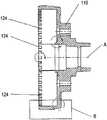
- FIG. 1shows a cross-sectional view of a trailer brake hub and drum assembly, taken through the axis of rotation, with the teachings of the present invention applied thereto.
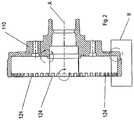
- FIG. 2shows a cross-sectional view of the brake hub-drum of a preferred embodiment of the present invention, taken through the axis of rotation.
- FIG. 3shows an enlarged cross-sectional view of portion B of FIG. 2 .
- FIG. 4shows a cross-sectional view of an alternative trailer hub and drum assembly, taken through the axis of rotation, according to the present invention.
- FIG. 1shows a trailer drum 10 and hub 15 , oriented with respect to a conventional backing plate 20 of a brake system (such as an electric brake for a cargo, industrial utility or RV trailer), as mounted on spindle or axle 17 for rotation about axis A.
- the present inventionincludes the provision of at least one sensor 22 on the enclosed side of backing plate 20 , facing the interior of drum 10 .
- sensor 22is mounted near the circumferential periphery of backing plate 20 , and spaced apart from the interior circumferential rim of drum 10 .
- the number of sensors mounted on backing plate 20 , and the type of sensor device used for sensor 22 in a given application,can be selected according to the operating conditions desired to be detected, and the relative cost and reliability of a given type of sensor.
- At least one detectable indicia 24is mounted on or formed into the interior circumferential rim of drum 10 , at one or more locations spaced apart from sensor 22 , but within the detectable range of the sensing tolerance of a given sensor 22 being used for a given application of the present invention.
- the detectable indicia illustratedis a notch or “tooth” cast, cut, machined, or otherwise formed into the interior circumferential rim of drum 10 .
- sensor 22can, for example, be a Hall effect or magnetic sensor device.
- sensor 22can be an optical device, detecting light intensity variations as indicia 24 pass close by.
- sensor 22 and indicia 24will pass close to each other, enough so that sensor 22 will detect that event, and pass the information along to a conventional remote operational indicator, monitor, or control device.
- the detectable indiciamay instead be reflective tape, an illumination source, a thermal emitter, or the like.
- Placing the sensor and the detectable indicia within the enclosure defined by the brake hub-drum and the backing plateserves to give greater protection for the sensor against road debris and the operating environment. This placement also can be consistent between different sized brake systems. Further, this placement is often sufficiently tolerant of variations in trailer load, trailer turning/maneuvers, bearing end play, and other disturbances which can effect the spacing and orientation of brake components, that sensor signal reliability is not adversely affected, particularly where the size (width, for example) of the detectable indicia is established for a given application, by reference to the sensor range, capacity, and expected usage environment. Also, in given applications, mounting the detectable indicia at this location allows the sensor to be mounted directly to form fitting features incorporated into other brake components.
- sensor 22can be mounted at any angle relative to the circumferential edge of backing plate 20 . Further, this mounting arrangement can take advantage of the “self-cleaning” characteristics of brake drums to maintain sensor reliability, and the fact that brake drums tend to be more resistant to adverse deflection issues which would affect the sensor/indicia air gap.
- indicia 24can be spaced apart equally or at varying distances from each other. Also, indicia 24 can be of a uniform size and shape in certain applications, or formed of different sizes and shapes for other detection purposes.
- FIG. 2shows a preferred embodiment of trailer hub-drum 110 according to the teachings of the present invention, with indicia 124 used for sensing wheel speed formed in the interior circumference of the drum rim.
- indicia 124can, for example, be a formed as a plurality of teeth cut or cast into the interior circumferential rim, and in a pattern equally spaced apart along the entire interior rim. Using wider teeth than sensor 22 would otherwise require for such indicia, allows the wheel speed to be reliably detected regardless of vehicle loading and other angular movement forces relative to the sensor/indicia orientation.
- indicia 124can include a chamfer or inclined end 124 a .
- the senor and/or indicia 124can be partially exposed to the environment outside of the enclosure created between hub-drum 110 and the backing plate.
- the backing platecan be mounted further within hub-drum 110 , and/or the sensor can be mounted on the exposed side of the backing plate.
- the sensormay be mounted to slide over the indicia, rather than move past the indicia spaced apart therefrom.
- FIG. 4shows another preferred embodiment of the present invention.
- the corresponding sensor 22 ais mounted to a brake structural member at its radial or circumferential periphery, such as a cast iron spider 25 , which is at least partially covered by a debris shield 26 spaced apart from the spider along Axis A.
- a brake structural membersuch as a cast iron spider 25
- a debris shield 26spaced apart from the spider along Axis A.
- the present inventioncould be applied to hydraulic brake systems using a rotatable brake drum.
Landscapes
- Engineering & Computer Science (AREA)
- Mechanical Engineering (AREA)
- Transportation (AREA)
- General Engineering & Computer Science (AREA)
- Physics & Mathematics (AREA)
- General Physics & Mathematics (AREA)
- Regulating Braking Force (AREA)
- Braking Arrangements (AREA)
Abstract
Description
- a. are inexpensive to manufacture and maintain,
- b. increase traffic safety during vehicle operation,
- c. minimize component weight,
- d. facilitate use and repair, and
- e. are durable and reliable over extended use and with a wider variety of vehicles.
Claims (10)
Priority Applications (2)
| Application Number | Priority Date | Filing Date | Title |
|---|---|---|---|
| US16/350,268US10889275B2 (en) | 2018-10-23 | 2018-10-23 | Wheel sensors within vehicular brake assemblies |
| US16/661,727US11066051B2 (en) | 2018-10-23 | 2019-10-23 | Wheel sensors within vehicular brake assemblies |
Applications Claiming Priority (1)
| Application Number | Priority Date | Filing Date | Title |
|---|---|---|---|
| US16/350,268US10889275B2 (en) | 2018-10-23 | 2018-10-23 | Wheel sensors within vehicular brake assemblies |
Related Child Applications (1)
| Application Number | Title | Priority Date | Filing Date |
|---|---|---|---|
| US16/661,727Continuation-In-PartUS11066051B2 (en) | 2018-10-23 | 2019-10-23 | Wheel sensors within vehicular brake assemblies |
Publications (2)
| Publication Number | Publication Date |
|---|---|
| US20200122698A1 US20200122698A1 (en) | 2020-04-23 |
| US10889275B2true US10889275B2 (en) | 2021-01-12 |
Family
ID=70280326
Family Applications (1)
| Application Number | Title | Priority Date | Filing Date |
|---|---|---|---|
| US16/350,268Active2039-04-19US10889275B2 (en) | 2018-10-23 | 2018-10-23 | Wheel sensors within vehicular brake assemblies |
Country Status (1)
| Country | Link |
|---|---|
| US (1) | US10889275B2 (en) |
Citations (23)
| Publication number | Priority date | Publication date | Assignee | Title |
|---|---|---|---|---|
| US3812391A (en)* | 1972-06-16 | 1974-05-21 | Rockwell International Corp | Wheel speed sensor |
| US4698536A (en)* | 1985-04-16 | 1987-10-06 | Toyota Jidosha Kabushiki Kaisha | Built-in wheel speed sensor structure for a car |
| US4907445A (en)* | 1987-12-28 | 1990-03-13 | Koyo Seiko Co., Ltd. | Automobile wheel bearing unit |
| US5281911A (en)* | 1991-11-08 | 1994-01-25 | Eaton Corporation | Vehicle wheel speed sensor employing a locating plate |
| US5476272A (en)* | 1994-01-19 | 1995-12-19 | Federal-Mogul Corporation | Speed sensor ring for vehicle anti-lock brake system |
| US5491407A (en)* | 1995-02-03 | 1996-02-13 | Kearney-National, Inc. | Wheel bearing speed sensor |
| US5678933A (en)* | 1995-01-20 | 1997-10-21 | Nsk Ltd. | Speed sensing rolling bearing unit |
| US20030047363A1 (en)* | 2001-09-07 | 2003-03-13 | Yohei Makuta | Wheel structure |
| US6568512B1 (en)* | 2002-05-16 | 2003-05-27 | International Truck Intellectual Property Company, Llc | Corrosion resistant cast-in insert exciter ring |
| US20030110860A1 (en)* | 2001-12-14 | 2003-06-19 | Ntn Corporation | Vehicle mounted bearing assembly |
| US20030122539A1 (en)* | 2001-10-17 | 2003-07-03 | Heimann Rudy J. | Signal wheel |
| US20030201766A1 (en)* | 2002-04-29 | 2003-10-30 | Faetanini Steven E. | Vehicle wheel bearing, wheel-speed sensor mechanism assembly, and wheel speed sensor |
| US20030234578A1 (en)* | 2002-03-08 | 2003-12-25 | Ntn Corporation | Rotation detecting device and anti-skid braking system using the same |
| US20040187581A1 (en)* | 2003-03-24 | 2004-09-30 | Masahiko Kamiya | Brake noise detection device |
| US20060091723A1 (en)* | 2004-10-29 | 2006-05-04 | Gunite Corporation | Exciter ring for a brake rotor |
| US20060124411A1 (en)* | 2004-12-10 | 2006-06-15 | The Boler Company | Corrosion-resistant ABS tone ring |
| US20100288411A1 (en)* | 2004-11-12 | 2010-11-18 | Richard Loewe | Tire Pressure Maintenance Device |
| US20110067963A1 (en)* | 2008-04-04 | 2011-03-24 | Knorr-Bremse Systeme Fuer Nutzfahrzeuge Gmbh | Arrangement of a Brake Disc on a Wheel Hub |
| US20130255366A1 (en)* | 2010-11-26 | 2013-10-03 | Fredrik Seglo | Brake Monitoring Device And Components Associated Therewith |
| US20180290637A1 (en)* | 2017-04-06 | 2018-10-11 | Hendrickson Usa, L.L.C. | Tone ring with protective filler |
| US20190101565A1 (en)* | 2017-10-03 | 2019-04-04 | Ford Global Technologies, Llc | Wheel-speed tone ring apparatus |
| US20190309810A1 (en)* | 2018-04-10 | 2019-10-10 | Bendix Spicer Foundation Brake Llc | Thermally Isolated Composite Exciter Ring |
| US20200122692A1 (en)* | 2018-10-23 | 2020-04-23 | Dexter Axle Company | Wheel sensors within vehicular brake assemblies |
- 2018
- 2018-10-23USUS16/350,268patent/US10889275B2/enactiveActive
Patent Citations (23)
| Publication number | Priority date | Publication date | Assignee | Title |
|---|---|---|---|---|
| US3812391A (en)* | 1972-06-16 | 1974-05-21 | Rockwell International Corp | Wheel speed sensor |
| US4698536A (en)* | 1985-04-16 | 1987-10-06 | Toyota Jidosha Kabushiki Kaisha | Built-in wheel speed sensor structure for a car |
| US4907445A (en)* | 1987-12-28 | 1990-03-13 | Koyo Seiko Co., Ltd. | Automobile wheel bearing unit |
| US5281911A (en)* | 1991-11-08 | 1994-01-25 | Eaton Corporation | Vehicle wheel speed sensor employing a locating plate |
| US5476272A (en)* | 1994-01-19 | 1995-12-19 | Federal-Mogul Corporation | Speed sensor ring for vehicle anti-lock brake system |
| US5678933A (en)* | 1995-01-20 | 1997-10-21 | Nsk Ltd. | Speed sensing rolling bearing unit |
| US5491407A (en)* | 1995-02-03 | 1996-02-13 | Kearney-National, Inc. | Wheel bearing speed sensor |
| US20030047363A1 (en)* | 2001-09-07 | 2003-03-13 | Yohei Makuta | Wheel structure |
| US20030122539A1 (en)* | 2001-10-17 | 2003-07-03 | Heimann Rudy J. | Signal wheel |
| US20030110860A1 (en)* | 2001-12-14 | 2003-06-19 | Ntn Corporation | Vehicle mounted bearing assembly |
| US20030234578A1 (en)* | 2002-03-08 | 2003-12-25 | Ntn Corporation | Rotation detecting device and anti-skid braking system using the same |
| US20030201766A1 (en)* | 2002-04-29 | 2003-10-30 | Faetanini Steven E. | Vehicle wheel bearing, wheel-speed sensor mechanism assembly, and wheel speed sensor |
| US6568512B1 (en)* | 2002-05-16 | 2003-05-27 | International Truck Intellectual Property Company, Llc | Corrosion resistant cast-in insert exciter ring |
| US20040187581A1 (en)* | 2003-03-24 | 2004-09-30 | Masahiko Kamiya | Brake noise detection device |
| US20060091723A1 (en)* | 2004-10-29 | 2006-05-04 | Gunite Corporation | Exciter ring for a brake rotor |
| US20100288411A1 (en)* | 2004-11-12 | 2010-11-18 | Richard Loewe | Tire Pressure Maintenance Device |
| US20060124411A1 (en)* | 2004-12-10 | 2006-06-15 | The Boler Company | Corrosion-resistant ABS tone ring |
| US20110067963A1 (en)* | 2008-04-04 | 2011-03-24 | Knorr-Bremse Systeme Fuer Nutzfahrzeuge Gmbh | Arrangement of a Brake Disc on a Wheel Hub |
| US20130255366A1 (en)* | 2010-11-26 | 2013-10-03 | Fredrik Seglo | Brake Monitoring Device And Components Associated Therewith |
| US20180290637A1 (en)* | 2017-04-06 | 2018-10-11 | Hendrickson Usa, L.L.C. | Tone ring with protective filler |
| US20190101565A1 (en)* | 2017-10-03 | 2019-04-04 | Ford Global Technologies, Llc | Wheel-speed tone ring apparatus |
| US20190309810A1 (en)* | 2018-04-10 | 2019-10-10 | Bendix Spicer Foundation Brake Llc | Thermally Isolated Composite Exciter Ring |
| US20200122692A1 (en)* | 2018-10-23 | 2020-04-23 | Dexter Axle Company | Wheel sensors within vehicular brake assemblies |
Also Published As
| Publication number | Publication date |
|---|---|
| US20200122698A1 (en) | 2020-04-23 |
Similar Documents
| Publication | Publication Date | Title |
|---|---|---|
| US11066051B2 (en) | Wheel sensors within vehicular brake assemblies | |
| US20240253392A1 (en) | Aerodynamic Wheel Covers and Mounting Assemblies | |
| US10573100B2 (en) | Nut, in particular wheel or axle nut, washer, control device for wheel or axle nuts in vehicles and vehicle provided therewith | |
| US5011303A (en) | Integrated bearing provided with a pulser and with a sensor for equipping a motor vehicle wheel hub | |
| US7610998B2 (en) | Disc brake | |
| US8021052B2 (en) | Sensor-equipped bearing for wheel | |
| US5097701A (en) | Automobile wheel hub | |
| JPH07506425A (en) | Device for measuring rotational motion | |
| US20130275018A1 (en) | Vehicle brake monitoring apparatus and method | |
| ITTO950119U1 (en) | ROTATION SPEED DETECTION DEVICE WITH DETACHABLE SENSOR. | |
| KR0161509B1 (en) | Vehicle wheel speed sensor | |
| US20180290637A1 (en) | Tone ring with protective filler | |
| WO2015076198A1 (en) | Error state detection device for automobile tires | |
| US10889275B2 (en) | Wheel sensors within vehicular brake assemblies | |
| JP4864441B2 (en) | Wheel bearing with sensor | |
| US7336067B2 (en) | Sensor assembly, sealing device, and roller bearing apparatus for vehicles having integrated connector and ring | |
| JP2003262220A (en) | Structure provided with bearing device with sensor, and method of detecting abnormality of bearing device with sensor in structure | |
| AU2020371497B2 (en) | Wheel sensors within vehicular brake assemblies | |
| WO2010147004A1 (en) | System for monitoring tire air pressure | |
| US5121972A (en) | Device for cooling vehicle brake area | |
| US6955096B2 (en) | Monitoring the axial load acting on the hub of a motor vehicle wheel | |
| KR102160796B1 (en) | Air disk brake for commercial vehicle | |
| AU2018244114A1 (en) | Wheel end sensor mounting assembly for heavy-duty vehicles | |
| KR101966729B1 (en) | Disk wheel hub module for moniting commercial vehicle | |
| CN105691348B (en) | Safety belt Webbing take-up device, seat belt apparatus and vehicle |
Legal Events
| Date | Code | Title | Description |
|---|---|---|---|
| STPP | Information on status: patent application and granting procedure in general | Free format text:NON FINAL ACTION MAILED | |
| STPP | Information on status: patent application and granting procedure in general | Free format text:NOTICE OF ALLOWANCE MAILED -- APPLICATION RECEIVED IN OFFICE OF PUBLICATIONS | |
| AS | Assignment | Owner name:DEXTER AXLE COMPANY, INDIANA Free format text:ASSIGNMENT OF ASSIGNORS INTEREST;ASSIGNORS:BOLLINGER, STEVEN R.;CARRISON, MARKUS C.;LIEVORE, SAMUEL N.;REEL/FRAME:054526/0345 Effective date:20201202 | |
| STCF | Information on status: patent grant | Free format text:PATENTED CASE | |
| AS | Assignment | Owner name:BMO HARRIS BANK N.A., ILLINOIS Free format text:ABL SECURITY AGREEMENT;ASSIGNORS:DEXTER AXLE COMPANY LLC;DEXTER MARINE PRODUCTS OF GEORGIA, LLC;REEL/FRAME:057784/0868 Effective date:20211004 Owner name:CREDIT SUISSE AG, CAYMAN ISLANDS BRANCH, NEW YORK Free format text:FIRST LIEN SECURITY AGREEMENT;ASSIGNORS:DEXTER AXLE COMPANY LLC;DEXTER MARINE PRODUCTS OF GEORGIA, LLC;REEL/FRAME:057724/0266 Effective date:20211004 | |
| AS | Assignment | Owner name:CREDIT SUISSE AG, NEW YORK BRANCH, AS COLLATERAL AGENT, NEW YORK Free format text:SECURITY AGREEMENT (FIRST LIEN);ASSIGNORS:DEXTER AXLE COMPANY LLC (F/O/B DEXTER AXLE COMPANY);DEXTER MARINE PRODUCTS OF GEORGIA LLC;PROGRESS MFG. LLC;REEL/FRAME:061623/0474 Effective date:20221005 | |
| AS | Assignment | Owner name:DEXTER AXLE COMPANY LLC, INDIANA Free format text:CHANGE OF NAME;ASSIGNOR:DEXTER AXLE COMPANY;REEL/FRAME:065018/0933 Effective date:20210727 | |
| MAFP | Maintenance fee payment | Free format text:PAYMENT OF MAINTENANCE FEE, 4TH YEAR, LARGE ENTITY (ORIGINAL EVENT CODE: M1551); ENTITY STATUS OF PATENT OWNER: LARGE ENTITY Year of fee payment:4 |