US10888693B2 - Drug pellet injector needle and method - Google Patents
Drug pellet injector needle and methodDownload PDFInfo
- Publication number
- US10888693B2 US10888693B2US15/683,507US201715683507AUS10888693B2US 10888693 B2US10888693 B2US 10888693B2US 201715683507 AUS201715683507 AUS 201715683507AUS 10888693 B2US10888693 B2US 10888693B2
- Authority
- US
- United States
- Prior art keywords
- hub
- sheath
- tube
- orientation
- passageway
- Prior art date
- Legal status (The legal status is an assumption and is not a legal conclusion. Google has not performed a legal analysis and makes no representation as to the accuracy of the status listed.)
- Active, expires
Links
Images


Classifications
- A—HUMAN NECESSITIES
- A61—MEDICAL OR VETERINARY SCIENCE; HYGIENE
- A61M—DEVICES FOR INTRODUCING MEDIA INTO, OR ONTO, THE BODY; DEVICES FOR TRANSDUCING BODY MEDIA OR FOR TAKING MEDIA FROM THE BODY; DEVICES FOR PRODUCING OR ENDING SLEEP OR STUPOR
- A61M37/00—Other apparatus for introducing media into the body; Percutany, i.e. introducing medicines into the body by diffusion through the skin
- A61M37/0069—Devices for implanting pellets, e.g. markers or solid medicaments
- A—HUMAN NECESSITIES
- A61—MEDICAL OR VETERINARY SCIENCE; HYGIENE
- A61M—DEVICES FOR INTRODUCING MEDIA INTO, OR ONTO, THE BODY; DEVICES FOR TRANSDUCING BODY MEDIA OR FOR TAKING MEDIA FROM THE BODY; DEVICES FOR PRODUCING OR ENDING SLEEP OR STUPOR
- A61M31/00—Devices for introducing or retaining media, e.g. remedies, in cavities of the body
- A61M31/007—Injectors for solid bodies, e.g. suppositories
- A—HUMAN NECESSITIES
- A61—MEDICAL OR VETERINARY SCIENCE; HYGIENE
- A61B—DIAGNOSIS; SURGERY; IDENTIFICATION
- A61B17/00—Surgical instruments, devices or methods
- A61B17/34—Trocars; Puncturing needles
- A61B17/3401—Puncturing needles for the peridural or subarachnoid space or the plexus, e.g. for anaesthesia
- A—HUMAN NECESSITIES
- A61—MEDICAL OR VETERINARY SCIENCE; HYGIENE
- A61B—DIAGNOSIS; SURGERY; IDENTIFICATION
- A61B17/00—Surgical instruments, devices or methods
- A61B17/34—Trocars; Puncturing needles
- A61B17/3468—Trocars; Puncturing needles for implanting or removing devices, e.g. prostheses, implants, seeds, wires
- A—HUMAN NECESSITIES
- A61—MEDICAL OR VETERINARY SCIENCE; HYGIENE
- A61M—DEVICES FOR INTRODUCING MEDIA INTO, OR ONTO, THE BODY; DEVICES FOR TRANSDUCING BODY MEDIA OR FOR TAKING MEDIA FROM THE BODY; DEVICES FOR PRODUCING OR ENDING SLEEP OR STUPOR
- A61M5/00—Devices for bringing media into the body in a subcutaneous, intra-vascular or intramuscular way; Accessories therefor, e.g. filling or cleaning devices, arm-rests
- A61M5/14—Infusion devices, e.g. infusing by gravity; Blood infusion; Accessories therefor
- A61M5/158—Needles for infusions; Accessories therefor, e.g. for inserting infusion needles, or for holding them on the body
- A—HUMAN NECESSITIES
- A61—MEDICAL OR VETERINARY SCIENCE; HYGIENE
- A61M—DEVICES FOR INTRODUCING MEDIA INTO, OR ONTO, THE BODY; DEVICES FOR TRANSDUCING BODY MEDIA OR FOR TAKING MEDIA FROM THE BODY; DEVICES FOR PRODUCING OR ENDING SLEEP OR STUPOR
- A61M5/00—Devices for bringing media into the body in a subcutaneous, intra-vascular or intramuscular way; Accessories therefor, e.g. filling or cleaning devices, arm-rests
- A61M5/178—Syringes
- A61M5/31—Details
- A61M5/315—Pistons; Piston-rods; Guiding, blocking or restricting the movement of the rod or piston; Appliances on the rod for facilitating dosing ; Dosing mechanisms
- A61M5/31511—Piston or piston-rod constructions, e.g. connection of piston with piston-rod
- A61M5/31515—Connection of piston with piston rod
- A—HUMAN NECESSITIES
- A61—MEDICAL OR VETERINARY SCIENCE; HYGIENE
- A61M—DEVICES FOR INTRODUCING MEDIA INTO, OR ONTO, THE BODY; DEVICES FOR TRANSDUCING BODY MEDIA OR FOR TAKING MEDIA FROM THE BODY; DEVICES FOR PRODUCING OR ENDING SLEEP OR STUPOR
- A61M5/00—Devices for bringing media into the body in a subcutaneous, intra-vascular or intramuscular way; Accessories therefor, e.g. filling or cleaning devices, arm-rests
- A61M5/178—Syringes
- A61M5/31—Details
- A61M5/315—Pistons; Piston-rods; Guiding, blocking or restricting the movement of the rod or piston; Appliances on the rod for facilitating dosing ; Dosing mechanisms
- A61M5/31565—Administration mechanisms, i.e. constructional features, modes of administering a dose
- A61M5/31576—Constructional features or modes of drive mechanisms for piston rods
- A61M5/31583—Constructional features or modes of drive mechanisms for piston rods based on rotational translation, i.e. movement of piston rod is caused by relative rotation between the user activated actuator and the piston rod
- A61M5/31586—Constructional features or modes of drive mechanisms for piston rods based on rotational translation, i.e. movement of piston rod is caused by relative rotation between the user activated actuator and the piston rod performed by rotationally moving or pivoted actuator, e.g. an injection lever or handle
- A—HUMAN NECESSITIES
- A61—MEDICAL OR VETERINARY SCIENCE; HYGIENE
- A61M—DEVICES FOR INTRODUCING MEDIA INTO, OR ONTO, THE BODY; DEVICES FOR TRANSDUCING BODY MEDIA OR FOR TAKING MEDIA FROM THE BODY; DEVICES FOR PRODUCING OR ENDING SLEEP OR STUPOR
- A61M5/00—Devices for bringing media into the body in a subcutaneous, intra-vascular or intramuscular way; Accessories therefor, e.g. filling or cleaning devices, arm-rests
- A61M5/178—Syringes
- A61M5/31—Details
- A61M5/32—Needles; Details of needles pertaining to their connection with syringe or hub; Accessories for bringing the needle into, or holding the needle on, the body; Devices for protection of needles
- A61M5/3286—Needle tip design, e.g. for improved penetration
- A—HUMAN NECESSITIES
- A61—MEDICAL OR VETERINARY SCIENCE; HYGIENE
- A61M—DEVICES FOR INTRODUCING MEDIA INTO, OR ONTO, THE BODY; DEVICES FOR TRANSDUCING BODY MEDIA OR FOR TAKING MEDIA FROM THE BODY; DEVICES FOR PRODUCING OR ENDING SLEEP OR STUPOR
- A61M5/00—Devices for bringing media into the body in a subcutaneous, intra-vascular or intramuscular way; Accessories therefor, e.g. filling or cleaning devices, arm-rests
- A61M5/178—Syringes
- A61M5/31—Details
- A61M5/32—Needles; Details of needles pertaining to their connection with syringe or hub; Accessories for bringing the needle into, or holding the needle on, the body; Devices for protection of needles
- A61M5/3293—Needles; Details of needles pertaining to their connection with syringe or hub; Accessories for bringing the needle into, or holding the needle on, the body; Devices for protection of needles characterised by features of the needle hub
- G—PHYSICS
- G09—EDUCATION; CRYPTOGRAPHY; DISPLAY; ADVERTISING; SEALS
- G09B—EDUCATIONAL OR DEMONSTRATION APPLIANCES; APPLIANCES FOR TEACHING, OR COMMUNICATING WITH, THE BLIND, DEAF OR MUTE; MODELS; PLANETARIA; GLOBES; MAPS; DIAGRAMS
- G09B23/00—Models for scientific, medical, or mathematical purposes, e.g. full-sized devices for demonstration purposes
- G09B23/28—Models for scientific, medical, or mathematical purposes, e.g. full-sized devices for demonstration purposes for medicine
- G09B23/285—Models for scientific, medical, or mathematical purposes, e.g. full-sized devices for demonstration purposes for medicine for injections, endoscopy, bronchoscopy, sigmoidscopy, insertion of contraceptive devices or enemas
- A—HUMAN NECESSITIES
- A61—MEDICAL OR VETERINARY SCIENCE; HYGIENE
- A61B—DIAGNOSIS; SURGERY; IDENTIFICATION
- A61B90/00—Instruments, implements or accessories specially adapted for surgery or diagnosis and not covered by any of the groups A61B1/00 - A61B50/00, e.g. for luxation treatment or for protecting wound edges
- A61B90/39—Markers, e.g. radio-opaque or breast lesions markers
- A61B2090/3966—Radiopaque markers visible in an X-ray image
- A—HUMAN NECESSITIES
- A61—MEDICAL OR VETERINARY SCIENCE; HYGIENE
- A61M—DEVICES FOR INTRODUCING MEDIA INTO, OR ONTO, THE BODY; DEVICES FOR TRANSDUCING BODY MEDIA OR FOR TAKING MEDIA FROM THE BODY; DEVICES FOR PRODUCING OR ENDING SLEEP OR STUPOR
- A61M25/00—Catheters; Hollow probes
- A61M2025/0007—Epidural catheters
- A—HUMAN NECESSITIES
- A61—MEDICAL OR VETERINARY SCIENCE; HYGIENE
- A61M—DEVICES FOR INTRODUCING MEDIA INTO, OR ONTO, THE BODY; DEVICES FOR TRANSDUCING BODY MEDIA OR FOR TAKING MEDIA FROM THE BODY; DEVICES FOR PRODUCING OR ENDING SLEEP OR STUPOR
- A61M25/00—Catheters; Hollow probes
- A61M25/0067—Catheters; Hollow probes characterised by the distal end, e.g. tips
- A61M25/0068—Static characteristics of the catheter tip, e.g. shape, atraumatic tip, curved tip or tip structure
- A61M25/007—Side holes, e.g. their profiles or arrangements; Provisions to keep side holes unblocked
Definitions
- the present disclosuregenerally relates to drug delivery devices, and more particularly to drug pellet injectors that are each configured to deploy one or more drug pellets.
- Drugsmay be delivered to patients by a variety of methods including oral, intravenous, intramuscular, inhalation, topical or subcutaneous delivery.
- the drugmay be delivered directly or locally to the treatment site (e.g., intrathecally, intraspinally, intraarticularly, etc.).
- the method of delivery chosendepends upon, among other things, the condition being treated, and the desired therapeutic concentration of the drug to be achieved in the patient and the duration of drug concentration that must be maintained.
- Drug depotssuch as, for example, drug pellets have been developed, which allow a drug to be introduced or administered to sites beneath the skin of a patient.
- the drug pelletsrelease the drug over a period of time.
- Drug pelletsallow the drug to be released from the pellet in a relatively uniform dose over weeks, months or even years.
- Administering drugs using drug pelletsis becoming especially important and popular in modulating the immune, inflammation and/or pain responses in treatment of chronic conditions including rheumatoid arthritis, osteoarthritis, sciatica, carpal tunnel syndrome, lower back pain, lower extremity pain, upper extremity pain, cancer, tissue pain and pain associated with injury or repair of cervical, thoracic, and/or lumbar vertebrae or intervertebral discs, rotator cuff, articular joint, TMJ, tendons, ligaments, muscles, and the like.
- Drug delivery deviceshave been developed to implant drug pellets within a patient.
- conventional devicesare often cumbersome, may be difficult to operate, may not prevent the drug pellets from being misdirected as they move through the device and/or include numerous components. This increases the total time needed to perform a procedure and increases the likelihood of user error.
- This disclosuredescribes improvements over these prior art technologies.
- an injection needlein one embodiment, is provided.
- the injection needleincludes a tube having opposite first and second ends.
- a hubis coupled to the first end.
- a sheathis coupled to the tube and the hub.
- the hubis movable relative to the tube to move the sheath between a first orientation in which the sheath covers an orifice in the second end and a second orientation in which the sheath is spaced apart from the orifice.
- FIG. 1is a perspective view of one embodiment of a drug pellet delivery system in accordance with the present principles of the present disclosure
- FIG. 2is a side view of the drug pellet delivery system shown in FIG. 1 ;
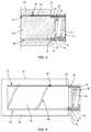
- FIG. 3is a side, cross sectional view of components of the drug pellet delivery system shown in FIG. 1 ;
- FIG. 4is a side view, in part phantom, of components of the drug pellet delivery system shown in FIG. 1 .
- a drug pellet delivery system and related methodsare discussed in terms of medical devices for delivering drug pellets, such as, for example, one or a plurality of drug depots.
- the system and methodmay be employed in applications that require at least one drug pellet to be implanted within a patient's body.
- the system and methodmay be employed in applications to deliver one or more drug pellets into the epidural space of the lumbrosacral spine of a patient.
- the drug pellet delivery systemincludes a Tuohy epidural needle containing a spring, a plunger, drug pellets, and a sheath covering an exit orifice of the needle.
- the needlecontains a mechanism to displace the sheath and activate the spring/plunger system to deploy the pellets.
- the mechanismincludes twisting the needle hub.
- the drug pellet delivery systemincludes a pellet injector needle having a small cannula that is about the size and shape of a standard Tuohy epidural needle.
- the pellet injector needleis the only component needed to perform a procedure to inject drug pellets in a target location.
- the pellet injector needleincludes a spring-loaded plunger inside a probe to reduce the risk of user error and simplify the process of pellet deployment.
- the drug pellet delivery systemincludes a pellet injector needle that is an all-in-one concept to reduce the number of components of the system the user interacts with to one, and greatly simplify the deployment process. This will reduce the total time to perform the procedure as well as reduce the number of user errors. Additionally, there is a significant reduction in the total volume of the product, reducing packaging size.
- the drug pellet delivery systemincludes a pellet injector needle having a sheath, such as, for example, a stopper that prevents drug pellets from falling out of the injector needle until the stopper is moved out of an opening of a cannula of the injector needle.
- the pellet injector needleincludes a spring that engages a plunger. The spring is configured to be compressed against the plunger. Once the stopper is moved, the system will automatically deploy the pellets.
- a hubsuch as, for example, a cap is attached to the cannula such that the cap can rotate about the cannula's center axis.
- a pinconnects the stopper to the cap.
- the capincludes a helical track that the pin slides in. As the cap is rotated clockwise, the pin slides along the track and moves the stopper axially toward the cap. In some embodiments, two rotations of the cap are required to trigger the pellet deployment system inside of the cannula.
- one or all of the components of the drug pellet delivery systemmay be disposable, peel-pack, pre-packed sterile devices.
- the components of the drug pellet delivery systemare configured for one time use and are disposed after they are used one time. However, it is contemplated that one or all of the components of the drug pellet delivery system may be reusable.
- the drug pellet delivery systemmay be configured as a kit with multiple sized and configured components, including, for example, various drug pellets or depots.
- the drug pellets or depotsare pre-loaded into a delivery device.
- one or more of the components of the drug pellet delivery systemare configured to be sterilized.
- the disclosed drug pellet delivery system and methodsmay be alternatively employed in a surgical treatment with a patient in a prone or supine position, and/or employ various surgical approaches, including anterior, posterior, posterior mid-line, direct lateral, postero-lateral, antero-lateral approaches, etc. in any body region.
- the system and methods of the present disclosuremay also be used on animals, bone models and other non-living substrates, such as, for example, in training, testing and demonstration.
- Rangesmay be expressed herein as from “about” or “approximately” one particular value and/or to “about” or “approximately” another particular value. Men such a range is expressed, another embodiment includes from the one particular value and/or to the other particular value. Similarly, when values are expressed as approximations, by use of the antecedent “about,” it will be understood that the particular value forms another embodiment. It is also understood that all spatial references, such as, for example, horizontal, vertical, top, upper, lower, bottom, left and right, are for illustrative purposes only and can be varied within the scope of the disclosure. For example, the references “upper” and “lower” are relative and used only in the context to the other, and are not necessarily “superior” and “inferior”.
- treating or “treatment” of a disease or conditionrefers to performing a procedure that may include administering one or more drug pellets or drug depots to a patient (human, normal or otherwise or other mammal), in an effort to alleviate signs or symptoms of the disease or condition. Alleviation can occur prior to signs or symptoms of the disease or condition appearing, as well as after their appearance.
- treating or treatmentincludes preventing or prevention of disease or undesirable condition (e.g., preventing the disease from occurring in a patient, who may be predisposed to the disease but has not yet been diagnosed as having it).
- treating or treatmentdoes not require complete alleviation of signs or symptoms, does not require a cure, and specifically includes procedures that have only a marginal effect on the patient.
- Treatmentcan include inhibiting the disease, e.g., arresting its development, or relieving the disease, e.g., causing regression of the disease.
- treatmentcan include reducing acute or chronic inflammation; alleviating pain and mitigating and inducing re-growth of new ligament, bone and other tissues; as an adjunct in surgery; and/or any repair procedure.
- tissueincludes soft tissue, ligaments, tendons, cartilage and/or bone unless specifically referred to otherwise.
- FIGS. 1-4there are illustrated components of a drug pellet delivery system 10 in accordance with the principles of the present disclosure.
- the components of drug pellet delivery system 10can be fabricated from biologically acceptable materials suitable for medical applications, including metals, synthetic polymers, ceramics and bone material and/or their composites, depending on the particular application and/or preference of a medical practitioner.
- the components of drug pellet delivery system 10individually or collectively, can be fabricated from materials such as stainless steel alloys, commercially pure titanium, titanium alloys, Grade 5 titanium, super-elastic titanium alloys, cobalt-chrome alloys, stainless steel alloys, superelastic metallic alloys (e.g., Nitinol, super elasto-plastic metals, such as GUM METAL® manufactured by Toyota Material Incorporated of Japan), ceramics and composites thereof such as calcium phosphate (e.g., SKELITETM manufactured by Biologix Inc.), thermoplastics such as polyaryletherketone (PAEK) including polyetheretherketone (PEEK), polyetherketoneketone (PEKK) and polyetherketone (PEK), carbon-PEEK composites,
- Various components of drug pellet delivery system 10may have material composites, including the above materials, to achieve various desired characteristics such as strength, rigidity, elasticity, compliance, biomechanical performance, durability and radiolucency or imaging preference.
- the components of drug pellet delivery system 10individually or collectively, may also be fabricated from a heterogeneous material such as a combination of two or more of the above-described materials.
- the components of drug pellet delivery system 10may be monolithically formed, integrally connected or include fastening elements and/or instruments, as described herein.
- drug pellet delivery system 10is used to deliver one or a plurality of drug pellets or drug depots.
- the drug pellet or drug depotsmay include an active agent, such as, for example, one or a plurality of drugs.
- Drug pellet delivery system 10includes a tube, such as, for example, a cannula 12 that extends along a longitudinal axis A between an end 14 and an opposite end 16 .
- Cannula 12includes a surface 18 that defines a passageway 20 and an orifice 22 that is in communication with passageway 20 .
- Cannula 12is curved at end 16 such that orifice 22 extends transverse to axis A.
- orifice 22extends perpendicular to axis A.
- orifice 22may be disposed at alternate orientations, relative to axis A, such as, for example, acute or obtuse, co-axial and/or may be offset or staggered.
- passageway 20may have various cross section configurations, such as, for example, circular, oval, oblong, triangular, rectangular, square, polygonal, irregular, uniform, non-uniform, variable, tubular and/or tapered. In some embodiments, passageway 20 has a uniform diameter along the entire length of cannula 12 .
- cannula 12is made from a biocompatible material that provides rigidity to cannula 12 , such as, for example, stainless steel. In some embodiments, cannula 12 is a Tuohy epidural needle.
- Cannula 12includes a circumferential cavity 24 that extends into surface 18 , as best shown in FIGS. 3 and 4 .
- a flange 26 of a capsuch as, for example, a hub 28 is positioned within cavity 24 to couple hub 28 to cannula 12 such that hub 28 is rotatable relative to cannula 12 about axis A.
- an end 30 of hub 28is positioned within passageway 20 to position flange 26 within cavity 24 .
- hub 28can be variously connected with cannula 12 , such as, for example, frictional engagement, threaded engagement, mutual grooves, screws, adhesive, nails, barbs and/or raised element.
- Hub 28includes a transverse surface 32 that directly engages an end surface 34 of cannula 12 when flange 26 is positioned within cavity 24 .
- Hub 28includes a handle having a gripping portion 36 , an inner portion 38 and a circumferential channel 40 positioned between portion 36 and portion 38 .
- Channel 40is configured for disposal of a stopper, such as, for example, a sheath 42 , as discussed herein.
- an outer surface of portion 36may have various surface configurations, such as, for example, smooth and/or surface configurations to enhance gripping, such as, for example, rough, arcuate, undulating, porous, semi-porous, dimpled, polished and/or textured, according to the requirements of a particular application.
- Portion 38includes a helical track 44 that extends into an outer surface of portion 38 , as shown in FIG. 4 .
- Track 44is configured to move sheath 42 between a first orientation in which sheath 42 covers at least a portion of orifice 22 and a second orientation in which sheath 44 is spaced apart from orifice 22 , as discussed herein.
- portion 38includes a wall 45 that extends perpendicular to axis A. Hub 28 is coupled to cannula 12 such that wall 45 extends across passageway 20 to block passageway 20 .
- System 10includes a plunger 46 movably positioned within passageway 20 , as shown in FIG. 2 .
- Plunger 46includes a body 48 having a cylindrical configuration and a tapered tip 50 .
- a biasing membersuch as, for example, a spring 52 is disposed within passageway 20 .
- Spring 52includes an end 54 that directly engages hub 28 and an end 56 that directly engages plunger 44 .
- One or a plurality of drug depots, such as, for example, drug pellets 58may be positioned within passageway 20 such that tip 50 of plunger 46 directly engages one of pellets 58 , as shown in FIG. 2 .
- Hub 28rotates relative to cannula 12 to move spring 52 between a compressed configuration in which pellets 58 are maintained within passageway 20 and an uncompressed configuration.
- spring 52moves plunger 46 in the direction shown by arrow B in FIG. 2 to push one or more of pellets 58 through orifice 22 of cannula 12 , as discussed herein.
- a pin 60is permanently fixed to an end 62 of sheath 42 to couple sheath 42 to hub 28 .
- Pin 60is positioned within track 44 such that when hub 28 is rotated relative to cannula 12 about axis A, pin 60 moves along track 44 to move sheath 42 relative to hub 28 and cannula 12 between a first orientation in which an end 64 of sheath 42 covers at least a portion of orifice 22 of cannula 12 , as shown in FIG. 1 , and a second orientation in which end 64 of sheath 42 is spaced apart from orifice 22 .
- sheath 42moves along axis A in the direction shown by arrow C in FIG. 2 .
- sheath 42When sheath 42 is in the first orientation, sheath 42 blocks orifice 22 to prevent pellets 58 from exiting cannula 12 through orifice 22 .
- spring 52moves from the compressed configuration to the uncompressed configuration to move plunger 46 in the direction shown by arrow B such that plunger 46 pushes at least one of pellets 58 through orifice 22 .
- system 10is employed with a surgical procedure, such as, to deliver one or more drug pellets or drug depots, such as, for example drug pellets 58 to a target location within a patient.
- the target locationis the epidural space of the lumbrosacral spine.
- system 10 and accessories thereof, described abovecan be employed to implant one or more drug pellets within a patient at a selected location, such as, for example, a surgical site.
- a medical practitionerobtains access to the surgical site in any appropriate manner, such as, for example, via an incision.
- system 10can be used in any existing surgical method or technique including open surgery, mini-open surgery, minimally invasive surgery and percutaneous surgical implantation.
- One or more drug pelletscan be delivered to the target location using system 10 .
- System 10may be assembled by inserting one or more drug pellets or drug depots, such as, for example, drug pellets 58 within passageway 20 of cannula 12 .
- one or more pellets 58are pre-loaded into cannula 12 . That is, system 10 may be delivered to a medical practitioner with pellets 58 already positioned within cannula 12 .
- Cannula 12is inserted through the incision to position cannula 12 within the patient such that orifice 22 of cannula 12 is positioned adjacent to the target location with sheath 42 in the first orientation to prevent pellets 58 from exiting cannula 12 through orifice 22 .
- Hub 28is then rotated relative to cannula 12 about axis A such that pin 60 moves along track 44 to move sheath 42 relative to hub 28 and cannula 12 along axis A in the direction shown by arrow C to move end 64 of sheath 42 such that end 64 is spaced apart from orifice 22 .
- Moving sheath 42 from the first orientation to the second orientationcauses spring 52 to move from the compressed configuration to the uncompressed configuration to move plunger 46 in the direction shown by arrow B such that plunger 46 pushes at least one of pellets 58 through orifice 22 to the target location.
- At least one of the components of system 10can be made of radiolucent materials such as polymers.
- cannula 12is made from a radiopaque material. Radiomarkers may be included for identification under x-ray, fluoroscopy, CT or other imaging techniques.
- cannula 12is removed from the patient and the incision is closed.
Landscapes
- Health & Medical Sciences (AREA)
- Engineering & Computer Science (AREA)
- Life Sciences & Earth Sciences (AREA)
- General Health & Medical Sciences (AREA)
- Veterinary Medicine (AREA)
- Biomedical Technology (AREA)
- Heart & Thoracic Surgery (AREA)
- Public Health (AREA)
- Animal Behavior & Ethology (AREA)
- Anesthesiology (AREA)
- Hematology (AREA)
- Surgery (AREA)
- Medical Informatics (AREA)
- Vascular Medicine (AREA)
- Molecular Biology (AREA)
- Nuclear Medicine, Radiotherapy & Molecular Imaging (AREA)
- Pathology (AREA)
- Dermatology (AREA)
- General Physics & Mathematics (AREA)
- Physics & Mathematics (AREA)
- Chemical & Material Sciences (AREA)
- Mathematical Optimization (AREA)
- Radiology & Medical Imaging (AREA)
- Algebra (AREA)
- Computational Mathematics (AREA)
- Pulmonology (AREA)
- Mathematical Analysis (AREA)
- Medicinal Chemistry (AREA)
- Mathematical Physics (AREA)
- Pure & Applied Mathematics (AREA)
- Business, Economics & Management (AREA)
- Educational Administration (AREA)
- Educational Technology (AREA)
- Theoretical Computer Science (AREA)
- Infusion, Injection, And Reservoir Apparatuses (AREA)
Abstract
Description
Claims (19)
Priority Applications (4)
| Application Number | Priority Date | Filing Date | Title |
|---|---|---|---|
| US15/683,507US10888693B2 (en) | 2017-08-22 | 2017-08-22 | Drug pellet injector needle and method |
| EP18183623.0AEP3449970A1 (en) | 2017-08-22 | 2018-07-16 | Drug pellet injector needle and method |
| KR1020180096727AKR102647370B1 (en) | 2017-08-22 | 2018-08-20 | Drug pellet injector needle and method |
| US17/102,734US11672961B2 (en) | 2017-08-22 | 2020-11-24 | Drug pellet injector needle and method technical field |
Applications Claiming Priority (1)
| Application Number | Priority Date | Filing Date | Title |
|---|---|---|---|
| US15/683,507US10888693B2 (en) | 2017-08-22 | 2017-08-22 | Drug pellet injector needle and method |
Related Child Applications (1)
| Application Number | Title | Priority Date | Filing Date |
|---|---|---|---|
| US17/102,734DivisionUS11672961B2 (en) | 2017-08-22 | 2020-11-24 | Drug pellet injector needle and method technical field |
Publications (2)
| Publication Number | Publication Date |
|---|---|
| US20190060625A1 US20190060625A1 (en) | 2019-02-28 |
| US10888693B2true US10888693B2 (en) | 2021-01-12 |
Family
ID=62975903
Family Applications (2)
| Application Number | Title | Priority Date | Filing Date |
|---|---|---|---|
| US15/683,507Active2038-09-17US10888693B2 (en) | 2017-08-22 | 2017-08-22 | Drug pellet injector needle and method |
| US17/102,734Active2038-09-01US11672961B2 (en) | 2017-08-22 | 2020-11-24 | Drug pellet injector needle and method technical field |
Family Applications After (1)
| Application Number | Title | Priority Date | Filing Date |
|---|---|---|---|
| US17/102,734Active2038-09-01US11672961B2 (en) | 2017-08-22 | 2020-11-24 | Drug pellet injector needle and method technical field |
Country Status (3)
| Country | Link |
|---|---|
| US (2) | US10888693B2 (en) |
| EP (1) | EP3449970A1 (en) |
| KR (1) | KR102647370B1 (en) |
Families Citing this family (2)
| Publication number | Priority date | Publication date | Assignee | Title |
|---|---|---|---|---|
| KR102535239B1 (en) | 2021-11-05 | 2023-05-30 | 남호진 | Manufacturing method of bus bar for battery and bus bar for battery manufactured thereby |
| KR102866214B1 (en) | 2022-07-21 | 2025-09-30 | 남호진 | Continuous automation manufacturing device of bus bar for battery |
Citations (30)
| Publication number | Priority date | Publication date | Assignee | Title |
|---|---|---|---|---|
| US2513014A (en)* | 1946-11-18 | 1950-06-27 | Abbott Lab | Apparatus for implanting medicinal pellets subcutaneously |
| US2850013A (en) | 1956-03-20 | 1958-09-02 | Cordis Nat | Animal pellet injector gun |
| US2922420A (en)* | 1957-11-29 | 1960-01-26 | Sierra Eng Co | Epidural needle |
| US4377380A (en)* | 1980-12-15 | 1983-03-22 | Leslie Vadas | Dual plunger dental amalgam dispenser |
| US4673387A (en) | 1985-05-06 | 1987-06-16 | N. J. Phillips Pty. Limited | Pellet injector |
| US4790312A (en)* | 1987-01-20 | 1988-12-13 | Becton Dickinson Acutecare, Inc. | Surgical knife |
| US4846811A (en) | 1987-01-29 | 1989-07-11 | International Medical Innovators, Inc. | Sliding sheath for medical needles |
| US4926877A (en)* | 1989-04-24 | 1990-05-22 | Bookwalter John R | Biopsy needle with completely closable cutting end bore |
| US5281197A (en)* | 1992-07-27 | 1994-01-25 | Symbiosis Corporation | Endoscopic hemostatic agent delivery system |
| US5284479A (en) | 1989-08-30 | 1994-02-08 | N.V. Nederlandsche Apparatenfabriek Nedap | Implanter |
| US5358474A (en)* | 1991-07-02 | 1994-10-25 | Intermed, Inc. | Subcutaneous drug delivery device |
| US5542920A (en) | 1994-09-12 | 1996-08-06 | Delab | Needle-less parenteral introduction device |
| US5695463A (en) | 1994-09-27 | 1997-12-09 | Societe De Conseils De Recherches Et D'applications | Safety injection device |
| US5997513A (en) | 1995-11-22 | 1999-12-07 | Smith; Jerry A. | Syringe cover cooperating with needle cover |
| US20050038355A1 (en)* | 2003-08-13 | 2005-02-17 | Gellman Barry N. | Marking biopsy sites |
| US20090148500A1 (en) | 2007-12-04 | 2009-06-11 | Lawter James R | Medicinal implant cartridge |
| US20090270672A1 (en) | 2007-01-09 | 2009-10-29 | Fago Frank M | Needle Cap Ejector for Radiation Shielded Syringe |
| US7794432B2 (en) | 2004-08-06 | 2010-09-14 | Meridian Medical Technologies, Inc. | Automatic injector with kickback attenuation |
| US7918821B2 (en) | 2009-05-05 | 2011-04-05 | Mahurkar Sakharam D | Universal safety syringe |
| US7988676B1 (en) | 2002-01-24 | 2011-08-02 | Robin Scott Gray | Syringe and method of using |
| US8048035B2 (en) | 2004-08-06 | 2011-11-01 | Meridian Medical Technologies, Inc. | Automatic injector with needle cover |
| US20120209247A1 (en) | 2009-07-15 | 2012-08-16 | Wuxi Yushou Medical Applicance Ltd., | Safe Disposable Injector with Changeable and Automatically Retractable Needle |
| US8657840B2 (en)* | 2011-02-17 | 2014-02-25 | Gyrus Ent L.L.C. | Surgical instrument with distal suction capability |
| US20140081210A1 (en)* | 2011-05-25 | 2014-03-20 | Access Scientific, Llc | Access device |
| US9289563B2 (en) | 2011-02-23 | 2016-03-22 | Pharma Consult Ges.M.B.H. | Syringe with syringe barrel, syringe head and ejector unit |
| US20160376820A1 (en) | 2015-06-26 | 2016-12-29 | Jerry Dean Glover | System for Latching and Unlatching A Swing Gate |
| US20170119974A1 (en)* | 2015-11-04 | 2017-05-04 | Custom Medical Applications, Inc. | Needles and related assemblies and methods |
| US20170281251A1 (en) | 2016-04-05 | 2017-10-05 | Warsaw Orthopedic, Inc | Surgical system and method |
| US10413313B2 (en)* | 2013-09-27 | 2019-09-17 | Release Medical, Inc. | Tissue incision device |
| WO2020012031A1 (en) | 2018-07-12 | 2020-01-16 | Sika Technology Ag | A self-adhering sealing device with an adhesive sealant layer |
Family Cites Families (6)
| Publication number | Priority date | Publication date | Assignee | Title |
|---|---|---|---|---|
| GB2240718A (en)* | 1990-02-09 | 1991-08-14 | Hundon Forge Ltd | Implanting device with needle cover |
| US5507807A (en)* | 1994-03-01 | 1996-04-16 | Shippert; Ronald D. | Apparatus for the release of a substance within a patient |
| US6659996B1 (en)* | 1995-11-09 | 2003-12-09 | Intermed, Inc. | Device for delivering biological agents |
| AU1331497A (en)* | 1995-12-18 | 1997-07-14 | Kerisma Medical Products, L.L.C. | Fiberoptic-guided interstitial seed manual applicator and seed cartridge |
| US20060122555A1 (en)* | 1998-04-10 | 2006-06-08 | Mark Hochman | Drug infusion device for neural axial and peripheral nerve tissue identification using exit pressure sensing |
| US20110306820A1 (en)* | 2010-06-14 | 2011-12-15 | Coloplast A/S | Method of treating incontinence |
- 2017
- 2017-08-22USUS15/683,507patent/US10888693B2/enactiveActive
- 2018
- 2018-07-16EPEP18183623.0Apatent/EP3449970A1/enactivePending
- 2018-08-20KRKR1020180096727Apatent/KR102647370B1/enactiveActive
- 2020
- 2020-11-24USUS17/102,734patent/US11672961B2/enactiveActive
Patent Citations (30)
| Publication number | Priority date | Publication date | Assignee | Title |
|---|---|---|---|---|
| US2513014A (en)* | 1946-11-18 | 1950-06-27 | Abbott Lab | Apparatus for implanting medicinal pellets subcutaneously |
| US2850013A (en) | 1956-03-20 | 1958-09-02 | Cordis Nat | Animal pellet injector gun |
| US2922420A (en)* | 1957-11-29 | 1960-01-26 | Sierra Eng Co | Epidural needle |
| US4377380A (en)* | 1980-12-15 | 1983-03-22 | Leslie Vadas | Dual plunger dental amalgam dispenser |
| US4673387A (en) | 1985-05-06 | 1987-06-16 | N. J. Phillips Pty. Limited | Pellet injector |
| US4790312A (en)* | 1987-01-20 | 1988-12-13 | Becton Dickinson Acutecare, Inc. | Surgical knife |
| US4846811A (en) | 1987-01-29 | 1989-07-11 | International Medical Innovators, Inc. | Sliding sheath for medical needles |
| US4926877A (en)* | 1989-04-24 | 1990-05-22 | Bookwalter John R | Biopsy needle with completely closable cutting end bore |
| US5284479A (en) | 1989-08-30 | 1994-02-08 | N.V. Nederlandsche Apparatenfabriek Nedap | Implanter |
| US5358474A (en)* | 1991-07-02 | 1994-10-25 | Intermed, Inc. | Subcutaneous drug delivery device |
| US5281197A (en)* | 1992-07-27 | 1994-01-25 | Symbiosis Corporation | Endoscopic hemostatic agent delivery system |
| US5542920A (en) | 1994-09-12 | 1996-08-06 | Delab | Needle-less parenteral introduction device |
| US5695463A (en) | 1994-09-27 | 1997-12-09 | Societe De Conseils De Recherches Et D'applications | Safety injection device |
| US5997513A (en) | 1995-11-22 | 1999-12-07 | Smith; Jerry A. | Syringe cover cooperating with needle cover |
| US7988676B1 (en) | 2002-01-24 | 2011-08-02 | Robin Scott Gray | Syringe and method of using |
| US20050038355A1 (en)* | 2003-08-13 | 2005-02-17 | Gellman Barry N. | Marking biopsy sites |
| US7794432B2 (en) | 2004-08-06 | 2010-09-14 | Meridian Medical Technologies, Inc. | Automatic injector with kickback attenuation |
| US8048035B2 (en) | 2004-08-06 | 2011-11-01 | Meridian Medical Technologies, Inc. | Automatic injector with needle cover |
| US20090270672A1 (en) | 2007-01-09 | 2009-10-29 | Fago Frank M | Needle Cap Ejector for Radiation Shielded Syringe |
| US20090148500A1 (en) | 2007-12-04 | 2009-06-11 | Lawter James R | Medicinal implant cartridge |
| US7918821B2 (en) | 2009-05-05 | 2011-04-05 | Mahurkar Sakharam D | Universal safety syringe |
| US20120209247A1 (en) | 2009-07-15 | 2012-08-16 | Wuxi Yushou Medical Applicance Ltd., | Safe Disposable Injector with Changeable and Automatically Retractable Needle |
| US8657840B2 (en)* | 2011-02-17 | 2014-02-25 | Gyrus Ent L.L.C. | Surgical instrument with distal suction capability |
| US9289563B2 (en) | 2011-02-23 | 2016-03-22 | Pharma Consult Ges.M.B.H. | Syringe with syringe barrel, syringe head and ejector unit |
| US20140081210A1 (en)* | 2011-05-25 | 2014-03-20 | Access Scientific, Llc | Access device |
| US10413313B2 (en)* | 2013-09-27 | 2019-09-17 | Release Medical, Inc. | Tissue incision device |
| US20160376820A1 (en) | 2015-06-26 | 2016-12-29 | Jerry Dean Glover | System for Latching and Unlatching A Swing Gate |
| US20170119974A1 (en)* | 2015-11-04 | 2017-05-04 | Custom Medical Applications, Inc. | Needles and related assemblies and methods |
| US20170281251A1 (en) | 2016-04-05 | 2017-10-05 | Warsaw Orthopedic, Inc | Surgical system and method |
| WO2020012031A1 (en) | 2018-07-12 | 2020-01-16 | Sika Technology Ag | A self-adhering sealing device with an adhesive sealant layer |
Non-Patent Citations (1)
| Title |
|---|
| European Search Report, European Patent Office, EP 18183623.0-1122, dated Jan. 31, 2019. |
Also Published As
| Publication number | Publication date |
|---|---|
| US20210077798A1 (en) | 2021-03-18 |
| US11672961B2 (en) | 2023-06-13 |
| KR20190021176A (en) | 2019-03-05 |
| EP3449970A1 (en) | 2019-03-06 |
| KR102647370B1 (en) | 2024-03-13 |
| US20190060625A1 (en) | 2019-02-28 |
Similar Documents
| Publication | Publication Date | Title |
|---|---|---|
| US11759614B2 (en) | Enhanced stylet for drug depot injector | |
| US12017050B2 (en) | Drug depot delivery system and method | |
| US9918753B2 (en) | Spinal implant system and method | |
| US20130018419A1 (en) | Spinal rod system and method | |
| US8764804B2 (en) | Bone fastener and methods of use | |
| US12042400B2 (en) | Spinal implant system and method | |
| US11672961B2 (en) | Drug pellet injector needle and method technical field | |
| US9247980B2 (en) | Device for performing a surgical procedure and method | |
| US9936988B2 (en) | Surgical system and method | |
| JP2021535780A (en) | Spinal implant system and method |
Legal Events
| Date | Code | Title | Description |
|---|---|---|---|
| AS | Assignment | Owner name:WARSAW ORTHOPEDIC, INC., INDIANA Free format text:ASSIGNMENT OF ASSIGNORS INTEREST;ASSIGNOR:KOCH, BRIAN D.;REEL/FRAME:043445/0755 Effective date:20170829 | |
| STPP | Information on status: patent application and granting procedure in general | Free format text:DOCKETED NEW CASE - READY FOR EXAMINATION | |
| STPP | Information on status: patent application and granting procedure in general | Free format text:NON FINAL ACTION MAILED | |
| STPP | Information on status: patent application and granting procedure in general | Free format text:RESPONSE TO NON-FINAL OFFICE ACTION ENTERED AND FORWARDED TO EXAMINER | |
| STPP | Information on status: patent application and granting procedure in general | Free format text:NON FINAL ACTION MAILED | |
| STPP | Information on status: patent application and granting procedure in general | Free format text:FINAL REJECTION MAILED | |
| STPP | Information on status: patent application and granting procedure in general | Free format text:ADVISORY ACTION MAILED | |
| STPP | Information on status: patent application and granting procedure in general | Free format text:NON FINAL ACTION MAILED | |
| STPP | Information on status: patent application and granting procedure in general | Free format text:RESPONSE TO NON-FINAL OFFICE ACTION ENTERED AND FORWARDED TO EXAMINER | |
| STPP | Information on status: patent application and granting procedure in general | Free format text:PUBLICATIONS -- ISSUE FEE PAYMENT VERIFIED | |
| STCF | Information on status: patent grant | Free format text:PATENTED CASE | |
| MAFP | Maintenance fee payment | Free format text:PAYMENT OF MAINTENANCE FEE, 4TH YEAR, LARGE ENTITY (ORIGINAL EVENT CODE: M1551); ENTITY STATUS OF PATENT OWNER: LARGE ENTITY Year of fee payment:4 |