US10888496B2 - Medicament vial assembly - Google Patents
Medicament vial assemblyDownload PDFInfo
- Publication number
- US10888496B2 US10888496B2US15/761,255US201615761255AUS10888496B2US 10888496 B2US10888496 B2US 10888496B2US 201615761255 AUS201615761255 AUS 201615761255AUS 10888496 B2US10888496 B2US 10888496B2
- Authority
- US
- United States
- Prior art keywords
- vial
- vial adapter
- adapter assembly
- annular
- stem
- Prior art date
- Legal status (The legal status is an assumption and is not a legal conclusion. Google has not performed a legal analysis and makes no representation as to the accuracy of the status listed.)
- Active, expires
Links
Images


Classifications
- A—HUMAN NECESSITIES
- A61—MEDICAL OR VETERINARY SCIENCE; HYGIENE
- A61J—CONTAINERS SPECIALLY ADAPTED FOR MEDICAL OR PHARMACEUTICAL PURPOSES; DEVICES OR METHODS SPECIALLY ADAPTED FOR BRINGING PHARMACEUTICAL PRODUCTS INTO PARTICULAR PHYSICAL OR ADMINISTERING FORMS; DEVICES FOR ADMINISTERING FOOD OR MEDICINES ORALLY; BABY COMFORTERS; DEVICES FOR RECEIVING SPITTLE
- A61J1/00—Containers specially adapted for medical or pharmaceutical purposes
- A61J1/14—Details; Accessories therefor
- A61J1/1406—Septums, pierceable membranes
- A—HUMAN NECESSITIES
- A61—MEDICAL OR VETERINARY SCIENCE; HYGIENE
- A61J—CONTAINERS SPECIALLY ADAPTED FOR MEDICAL OR PHARMACEUTICAL PURPOSES; DEVICES OR METHODS SPECIALLY ADAPTED FOR BRINGING PHARMACEUTICAL PRODUCTS INTO PARTICULAR PHYSICAL OR ADMINISTERING FORMS; DEVICES FOR ADMINISTERING FOOD OR MEDICINES ORALLY; BABY COMFORTERS; DEVICES FOR RECEIVING SPITTLE
- A61J1/00—Containers specially adapted for medical or pharmaceutical purposes
- A61J1/14—Details; Accessories therefor
- A61J1/20—Arrangements for transferring or mixing fluids, e.g. from vial to syringe
- A61J1/2003—Accessories used in combination with means for transfer or mixing of fluids, e.g. for activating fluid flow, separating fluids, filtering fluid or venting
- A61J1/2006—Piercing means
- A61J1/201—Piercing means having one piercing end
- A—HUMAN NECESSITIES
- A61—MEDICAL OR VETERINARY SCIENCE; HYGIENE
- A61J—CONTAINERS SPECIALLY ADAPTED FOR MEDICAL OR PHARMACEUTICAL PURPOSES; DEVICES OR METHODS SPECIALLY ADAPTED FOR BRINGING PHARMACEUTICAL PRODUCTS INTO PARTICULAR PHYSICAL OR ADMINISTERING FORMS; DEVICES FOR ADMINISTERING FOOD OR MEDICINES ORALLY; BABY COMFORTERS; DEVICES FOR RECEIVING SPITTLE
- A61J1/00—Containers specially adapted for medical or pharmaceutical purposes
- A61J1/14—Details; Accessories therefor
- A61J1/20—Arrangements for transferring or mixing fluids, e.g. from vial to syringe
- A61J1/2003—Accessories used in combination with means for transfer or mixing of fluids, e.g. for activating fluid flow, separating fluids, filtering fluid or venting
- A61J1/2048—Connecting means
- A61J1/2051—Connecting means having tap means, e.g. tap means activated by sliding
- A—HUMAN NECESSITIES
- A61—MEDICAL OR VETERINARY SCIENCE; HYGIENE
- A61J—CONTAINERS SPECIALLY ADAPTED FOR MEDICAL OR PHARMACEUTICAL PURPOSES; DEVICES OR METHODS SPECIALLY ADAPTED FOR BRINGING PHARMACEUTICAL PRODUCTS INTO PARTICULAR PHYSICAL OR ADMINISTERING FORMS; DEVICES FOR ADMINISTERING FOOD OR MEDICINES ORALLY; BABY COMFORTERS; DEVICES FOR RECEIVING SPITTLE
- A61J1/00—Containers specially adapted for medical or pharmaceutical purposes
- A61J1/14—Details; Accessories therefor
- A61J1/20—Arrangements for transferring or mixing fluids, e.g. from vial to syringe
- A61J1/2003—Accessories used in combination with means for transfer or mixing of fluids, e.g. for activating fluid flow, separating fluids, filtering fluid or venting
- A61J1/2048—Connecting means
- A61J1/2055—Connecting means having gripping means
- A—HUMAN NECESSITIES
- A61—MEDICAL OR VETERINARY SCIENCE; HYGIENE
- A61J—CONTAINERS SPECIALLY ADAPTED FOR MEDICAL OR PHARMACEUTICAL PURPOSES; DEVICES OR METHODS SPECIALLY ADAPTED FOR BRINGING PHARMACEUTICAL PRODUCTS INTO PARTICULAR PHYSICAL OR ADMINISTERING FORMS; DEVICES FOR ADMINISTERING FOOD OR MEDICINES ORALLY; BABY COMFORTERS; DEVICES FOR RECEIVING SPITTLE
- A61J1/00—Containers specially adapted for medical or pharmaceutical purposes
- A61J1/14—Details; Accessories therefor
- A61J1/20—Arrangements for transferring or mixing fluids, e.g. from vial to syringe
- A61J1/2003—Accessories used in combination with means for transfer or mixing of fluids, e.g. for activating fluid flow, separating fluids, filtering fluid or venting
- A61J1/2068—Venting means
- A61J1/2072—Venting means for internal venting
- A—HUMAN NECESSITIES
- A61—MEDICAL OR VETERINARY SCIENCE; HYGIENE
- A61J—CONTAINERS SPECIALLY ADAPTED FOR MEDICAL OR PHARMACEUTICAL PURPOSES; DEVICES OR METHODS SPECIALLY ADAPTED FOR BRINGING PHARMACEUTICAL PRODUCTS INTO PARTICULAR PHYSICAL OR ADMINISTERING FORMS; DEVICES FOR ADMINISTERING FOOD OR MEDICINES ORALLY; BABY COMFORTERS; DEVICES FOR RECEIVING SPITTLE
- A61J1/00—Containers specially adapted for medical or pharmaceutical purposes
- A61J1/14—Details; Accessories therefor
- A61J1/20—Arrangements for transferring or mixing fluids, e.g. from vial to syringe
- A61J1/2096—Combination of a vial and a syringe for transferring or mixing their contents
Definitions
- the present disclosurerelates generally to medical vial assemblies, and more particularly, to medical vials pre-attached with a vial adapter assembly for the transfer of gases/liquids/fluid or other substances to/from medical vials.
- cytotoxic drugshave generally been used to kill cancer cells.
- the use of cytotoxic drugs, in the treatment of cancer cellspresents specific dangers to all cells, both in the patient and in healthcare providers.
- the exposure to a health care provideris normally very small for each cytotoxic drug dose administration, evidence suggests that chronic, low-dose exposure can produce significant health problems. Accordingly, a system that allows the safe handling of hazardous drugs while significantly reducing and/or eliminating the exposure to providers would be of great benefit.
- Drugsare typically supplied in glass or plastic vials that are capped with a gas impermeable liquid seal or stopper.
- the vial contentsare a solid powder, such that a liquid needs to be injected for mixing (e.g., reconstitution).
- additional contentse.g., liquid
- the vialis intended to be sealed to liquid and gases, drug molecules in vapor phase can leak or pass around the sides of the stopper or through the stopper as the injection needle is withdrawn, thus presenting a hazard to the provider or clinician.
- the present disclosurerelates to medical vials pre-attached with a vial adapter assembly for the transfer of gases/liquids/fluid or other substances to/from medical vials.
- a vial adapter assemblyfor a closed fluid transfer system.
- the vial adapter assemblyincludes a vial adapter, and a vial collar.
- the vial adapterincludes a base defining an inner annular rim and an outer annular rim and a cavity therebetween; an annular stem extending from the base and defining an opening having a plurality of fingers extending around the opening thereof, wherein each finger defines a proximal recess and a distal recess formed therein; a cover supported on the outer annular rim, wherein an expansion chamber is defined within the cover and the base; and an adapter support situated within the cavity of the base.
- the adapter supportincludes a male stem extending in a first direction from the base, the male stem selectively connectable to and insertable into an open distal end of a syringe adapter, the male stem defining a lumen extending therethrough; a seal extending across the lumen of the male stem; and a spike extending in a second direction from the inner annular rim and into the opening of the annular stem, wherein the spike includes a first lumen being in fluid communication with the lumen of the male stem, and wherein the spike includes a second lumen being in fluid communication with the expansion chamber.
- the adapter supportfurther includes a bladder extending between the base and the cover.
- the vial collarincludes an annular body configured and dimensioned for sliding receipt within the annular stem of the vial adapter; at least one tab projecting from an outer surface of the annular body and being configured for selective receipt in distal recess and proximal recess of a respective finger of vial adapter; and at least one retainer projecting from an inner surface of the annular body.
- the vial adapter assemblymay include a first position where the vial collar is extended relative to the annular stem, and a second position where the vial collar is retracted relative to the annular stem.
- the at least one tab of the vial collarWhen the vial adapter assembly is in the first position, the at least one tab of the vial collar may be disposed within the distal recess of a respective finger of the plurality of fingers of the annular stem. When the vial adapter assembly is in the second position, the at least one tab of the vial collar may be disposed within the proximal recess of a respective finger of the plurality of fingers of the annular stem. When the vial adapter assembly is in the second position, the at least one tab of the vial collar may be disposed within the proximal recess of a respective finger of the plurality of fingers of the annular stem.
- the plurality of fingers of the annular stemmay be resilient.
- the spike of the vial adaptermay extend towards the annular body of the vial collar.
- the plurality of fingers of the annular stem of the vial adaptermay include two pair of diametrically opposed fingers.
- the at least one tab of the vial collarmay include two pair of diametrically opposed tabs.
- the at least one retainer of the vial adaptermay include two pair of diametrically opposed retainers.
- the spike of the vial adaptermay be configured to penetrate a stopper of a medical vial upon an actuation of the vial adapter assembly from the first position to the second position.
- a medical vial assemblyincludes a medical vial including a neck defining an opening into the vial, and a stopper disposed within the neck and closing the opening of the vial; and a vial adapter assembly connected to the neck of the medical vial.
- the vial adapter assemblyincludes a base defining an inner annular rim and an outer annular rim and a cavity therebetween; an annular stem extending from the base and defining an opening having a plurality of fingers extending around the opening thereof, wherein each finger defines a proximal recess and a distal recess formed therein; a cover supported on the outer annular rim, wherein an expansion chamber is defined within the cover and the base; and an adapter support situated within the cavity of the base.
- the adapter supportincludes a male stem extending in a first direction from the base, the male stem selectively connectable to and insertable into an open distal end of a syringe adapter, the male stem defining a lumen extending therethrough; a seal extending across the lumen of the male stem; and a spike extending in a second direction from the inner annular rim and into the opening of the annular stem, wherein the spike includes a first lumen being in fluid communication with the lumen of the male stem, and wherein the spike includes a second lumen being in fluid communication with the expansion chamber.
- the adapter supportfurther includes a bladder extending between the base and the cover.
- the medical vial assemblyfurther includes a vial collar connected to the neck of the medical vial.
- the vial collarincludes an annular body configured and dimensioned for sliding receipt within the annular stem of the vial adapter, and at least partially surrounding the neck of the medical vial; at least one tab projecting from an outer surface of the annular body and being configured for selective receipt in distal recess and proximal recess of a respective finger of vial adapter; and at least one retainer projecting from an inner surface of the annular body, wherein each retainer is snap-fit connected to the neck of the medical vial.
- the vial adapter assemblymay include a first position where the vial collar is extended relative to the annular stem, and a second position where the vial collar is retracted relative to the annular stem.
- the vial adapter assemblyWhen the vial adapter assembly is in the first position, the at least one tab of the vial collar may be disposed within the distal recess of a respective finger of the plurality of fingers of the annular stem.
- the vial adapter assemblyWhen the vial adapter assembly is in the second position, the at least one tab of the vial collar may be disposed within the proximal recess of a respective finger of the plurality of fingers of the annular stem.
- the spike of the vial adapter assemblyWhen the vial adapter assembly is in the second position, the spike of the vial adapter assembly may penetrate the stopper of the medical vial.
- the plurality of fingers of the annular stem of the vial adapter assemblymay be resilient.
- a tip of the spike of the vial adaptermay extend beyond the stopper of the medical vial when the vial adapter assembly is in the second position.
- the vial adapterincludes a base defining an inner annular rim and an outer annular rim and a cavity therebetween; and an annular stem extending from the base and defining an opening.
- the annular stemincludes a plurality of fingers extending around the opening thereof, wherein each finger terminates in a proximal-most retainer; and at least one distal-most retainer projecting radially inwardly from an inner surface of the annular stem.
- the vial adapterfurther includes a cover supported on the outer annular rim, wherein an expansion chamber is defined within the cover and the base; and an adapter support situated within the cavity of the base.
- the adapter supportincludes a male stem extending in a first direction from the base, the male stem selectively connectable to and insertable into an open distal end of a syringe adapter, the male stem defining a lumen extending therethrough; a seal extending across the lumen of the male stem; and a spike extending in a second direction from the inner annular rim and into the opening of the annular stem, wherein the spike includes a first lumen being in fluid communication with the lumen of the male stem, and wherein the spike includes a second lumen being in fluid communication with the expansion chamber.
- the vial adapteradditionally includes a bladder extending between the base and the cover.
- Each proximal-most retainer of the vial adaptermay be resilient.
- Each distal-most retainer of the vial adaptermay be resilient.
- the distal-most retainersmay be in axial registration with the spike.
- Each distal-most retainer of the vial adaptermay extend distally and radially inwardly.
- Each distal-most retainer of the vial adaptermay include a shoulder located distal of a tip of the spike.
- the spike of the vial adaptermay extend towards the plurality of fingers.
- the plurality of fingers of the vial adaptermay include two pair of diametrically opposed fingers.
- the at least one distal-most retainermay include two pair of diametrically opposed retainers.
- the spike of the vial adaptermay be configured to penetrate a stopper of a medical vial upon an insertion of a neck of the medical vial distally from the proximal-most retainers into engagement with the shoulder of the at least one distal-most retainer.
- a medical vial assemblyincludes a medical vial and a vial adapter.
- the medical vialincludes a neck defining an opening into the vial, and a stopper disposed within the neck and closing the opening of the vial.
- the vial adapterincludes a base defining an inner annular rim and an outer annular rim and a cavity therebetween; an annular stem extending from the base and defining an opening configured to receive the neck of the medical vial therein, the annular stem includes: a plurality of fingers extending around the opening thereof, wherein each finger terminates in a proximal-most retainer; and at least one distal-most retainer projecting radially inwardly from an inner surface of the annular stem, wherein each distal-most retainer is in snap-fit engagement with the neck of the medical vial.
- the vial adapterfurther includes a cover supported on the outer annular rim, wherein an expansion chamber is defined within the cover and the base; and an adapter support situated within the cavity of the base.
- the adapter supportincludes a male stem extending in a first direction from the base, the male stem selectively connectable to and insertable into an open distal end of a syringe adapter, the male stem defining a lumen extending therethrough; a seal extending across the lumen of the male stem; and a spike extending in a second direction from the inner annular rim and into the opening of the annular stem, wherein the spike includes a first lumen being in fluid communication with the lumen of the male stem, and wherein the spike includes a second lumen being in fluid communication with the expansion chamber.
- the vial adapteralso includes a bladder extending between the base and the cover.
- the vial adapter assemblymay include a first position where the proximal-most retainers are in engagement with the neck of the medical vial, and a second position where the distal-most retainers are in engagement with the neck of the medical vial. When when the vial adapter assembly is in the second position, the spike of the vial adapter assembly may penetrate the stopper of the medical vial.
- Each proximal-most retainer of the vial adaptermay be resilient.
- Each distal-most retainer of the vial adaptermay be resilient.
- the distal-most retainersmay be in axial registration with the spike.
- Each distal-most retainer of the vial adaptermay extend distally and radially inwardly.
- Each distal-most retainer of the vial adaptermay include a shoulder located distal of a tip of the spike.
- the spike of the vial adaptermay extend towards the plurality of fingers.
- the plurality of fingers of the vial adaptermay include two pair of diametrically opposed fingers.
- the at least one distal-most retainermay include two pair of diametrically opposed retainers.
- the spike of the vial adaptermay be configured to penetrate the stopper of the medical vial upon an insertion of the neck of the medical vial distally from the proximal-most retainers into engagement with the shoulder of the at least one distal-most retainer.
- the vial adapterincludes a base defining an inner annular rim and an outer annular rim and a cavity therebetween; and an annular stem extending from the base and defining an opening.
- the annular stemincludes a plurality of fingers extending around the opening thereof, wherein each finger terminates in a proximal-most retainer; at least one distal-most retainer projecting radially inwardly from an inner surface of the annular stem; and a pull tab extending from one of the plurality of fingers.
- the vial adapterfurther includes a cover supported on the outer annular rim, wherein an expansion chamber is defined within the cover and the base; and an adapter support situated within the cavity of the base.
- the adapter supportincludes a male stem extending in a first direction from the base, the male stem selectively connectable to and insertable into an open distal end of a syringe adapter, the male stem defining a lumen extending therethrough; a seal extending across the lumen of the male stem; and a spike extending in a second direction from the inner annular rim and into the opening of the annular stem, wherein the spike includes a first lumen being in fluid communication with the lumen of the male stem, and wherein the spike includes a second lumen being in fluid communication with the expansion chamber.
- This vial adapteralso includes a bladder extending between the base and the cover.
- Each proximal-most retainer of the vial adaptermay be resilient. Each distal-most retainer of the vial adapter may be resilient. The distal-most retainer may be in axial registration with the spike. Each distal-most retainer of the vial adapter may extend distally and radially inwardly. Each distal-most retainer of the vial adapter may include a shoulder located distal of a tip of the spike. The spike of the vial adapter may extend towards the plurality of fingers. The spike of the vial adapter may be configured to penetrate a stopper of a medical vial upon an insertion of a neck of the medical vial distally from the proximal-most retainers into engagement with the shoulder of the at least one distal-most retainer.
- a medical vial assemblyincludes a medical vial including a neck defining an opening into the vial, and a stopper disposed within the neck and closing the opening of the vial; and a vial adapter.
- the vial adapterincludes a base defining an inner annular rim and an outer annular rim and a cavity therebetween; and an annular stem extending from the base and defining an opening configured to receive the neck of the medical vial therein.
- the annular stemincludes a plurality of fingers extending around the opening thereof, wherein each finger terminates in a proximal-most retainer; at least one distal-most retainer projecting radially inwardly from an inner surface of the annular stem, wherein each distal-most retainer is in snap-fit engagement with the neck of the medical vial; and a pull tab extending from one of the plurality of fingers.
- the vial adapterfurther includes a cover supported on the outer annular rim, wherein an expansion chamber is defined within the cover and the base; and an adapter support situated within the cavity of the base.
- the adapter supportincludes a male stem extending in a first direction from the base, the male stem selectively connectable to and insertable into an open distal end of a syringe adapter, the male stem defining a lumen extending therethrough; a seal extending across the lumen of the male stem; and a spike extending in a second direction from the inner annular rim and into the opening of the annular stem, wherein the spike includes a first lumen being in fluid communication with the lumen of the male stem, and wherein the spike includes a second lumen being in fluid communication with the expansion chamber.
- This vial adapteralso includes a bladder extending between the base and the cover.
- Each proximal-most retainer of the vial adaptermay be resilient.
- Each distal-most retainer of the vial adaptermay be resilient.
- the distal-most retainersmay be in axial registration with the spike.
- Each distal-most retainer of the vial adaptermay extend distally and radially inwardly.
- Each distal-most retainer of the vial adaptermay include a shoulder located distal of a tip of the spike.
- the spike of the vial adaptermay extend towards the plurality of fingers.
- the spike of the vial adaptermay be configured to penetrate a stopper of a medical vial upon an insertion of a neck of the medical vial distally from the proximal-most retainers into engagement with the shoulder of the at least one distal-most retainer.
- a medical vial assemblyincludes a medical vial including a neck defining an opening into the vial, and a stopper disposed within the neck and closing the opening of the vial; and a vial adapter.
- the vial adapterincludes a base defining an inner annular rim and an outer annular rim and a cavity therebetween; and an annular stem extending from the base and defining an opening configured to receive the neck of the medical vial therein.
- the annular stemincludes at least one retainer projecting radially inwardly from an inner surface of the annular stem, wherein each retainer is spaced an axial distance from the opening of the annular stem, and wherein each retainer is configured for snap-fit engagement with the neck of the medical vial; and at least one gasket extending across the opening of the annular stem, wherein the at least one gasket forms a fluid tight seal between the annular stem of the vial adapter and the neck of the medical vial; a cover supported on the outer annular rim, wherein an expansion chamber is defined within the cover and the base; and an adapter support situated within the cavity of the base.
- the adapter supportincludes a male stem extending in a first direction from the base, the male stem selectively connectable to and insertable into an open distal end of a syringe adapter, the male stem defining a lumen extending therethrough; a seal extending across the lumen of the male stem; and a spike extending in a second direction from the inner annular rim and into the opening of the annular stem, wherein the spike includes a first lumen being in fluid communication with the lumen of the male stem, and wherein the spike includes a second lumen being in fluid communication with the expansion chamber.
- This vial adapteralso includes a bladder extending between the base and the cover.
- the at least one gasket of the annular stem of the vial adaptermay include a proximal gasket and a distal gasket, wherein each gasket defines a central opening therein.
- Each gasketmay be fabricated from at least one of a rubber or a thermoplastic elastomer.
- Each retainer of the vial adaptermay be resilient.
- the retainersmay be in axial registration with the spike.
- Each retainer of the vial adaptermay extend distally and radially inwardly.
- Each retainer of the vial adaptermay include a shoulder located distal of a tip of the spike.
- the spike of the vial adaptermay be configured to penetrate a stopper of a medical vial upon an insertion of a neck of the medical vial distally from engagement with the proximal gasket to engagement with the distal gasket and into engagement with the shoulder of the at least one retainer.
- FIG. 1is a side elevational view, with parts separated, of a medical vial and a vial adapter assembly according to an embodiment of the present disclosure
- FIG. 2is a perspective view, with parts separated, of the vial adapter assembly of FIG. 1 ;
- FIG. 3is a bottom perspective view of a vial adapter of the vial adapter assembly illustrating in FIG. 1 ;
- FIG. 4is a bottom perspective view of a locking collar of the vial adapter assembly illustrating in FIG. 1 ;
- FIG. 5is a perspective view of the vial adapter assembly of FIG. 1 , shown attached to the medical vial, illustrating the vial adapter assembly in a first, non-penetrating position;
- FIG. 6is a longitudinal, cross-sectional view of the vial adapter assembly and medical vial of FIG. 5 , as taken through 6 - 6 of FIG. 5 ;
- FIG. 7is a cross-sectional, perspective view of an annular stem and vial collar of the vial adapter assembly of FIGS. 1-6 ;
- FIG. 8is a side elevational view the vial adapter assembly of FIG. 1 shown attached to the medical vial, illustrating the vial adapter assembly in a second, penetrating position;
- FIG. 9is a longitudinal cross-sectional view of the vial adapter assembly and medical vial of FIG. 8 ;
- FIG. 10is a bottom perspective view of a vial adapter assembly according to another embodiment of the present disclosure.
- FIG. 11is a perspective view, with parts separated, of the vial adapter assembly of FIG. 10 ;
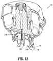
- FIG. 12is a longitudinal, cross-sectional view of the vial adapter assembly of FIGS. 10 and 11 , as taken through 12 - 12 of FIG. 10 ;
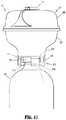
- FIG. 13is a side elevational view the vial adapter assembly of FIGS. 10-12 shown attached to the medical vial;
- FIG. 14is a longitudinal cross-sectional view of the vial adapter assembly and medical vial of FIG. 13 , illustrating the vial adapter assembly in a first, non-penetrating position;
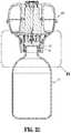
- FIG. 15is a longitudinal cross-sectional view of the vial adapter assembly and medical vial of FIG. 13 , illustrating the vial adapter assembly in a second, penetrating position;
- FIG. 16is a side elevational view a vial adapter assembly, according to yet another embodiment of the present disclosure, shown attached to the medical vial, illustrating the vial adapter assembly in a first, non-penetrating position;
- FIG. 17is a perspective view, with parts separated, of the vial adapter assembly of FIG. 16 ;
- FIG. 18is a longitudinal, cross-sectional view of FIG. 16 ;
- FIG. 19is a perspective, cross-sectional view of the vial adapter assembly of FIGS. 16-18 ;
- FIG. 20is an elevational view of a vial adapter assembly, according to still another embodiment of the present disclosure, shown attached to the medical vial, illustrating the vial adapter assembly in a first, non-penetrating position;
- FIG. 21is a perspective view, with parts separated, of the vial adapter assembly of FIG. 20 ;
- FIG. 22is a longitudinal, cross-sectional view of the vial adapter assembly and the medical vial of FIG. 20 ;
- FIG. 23is an enlarged view of the indicated area of detail of FIG. 22 ;
- FIG. 24is a perspective, cross-sectional view of the vial adapter assembly of FIGS. 20-23 .
- a medical vial assemblyincluding a medical vial “V” pre-connected, pre-loaded or pre-attached with a vial adapter assembly, e.g., vial adapter assembly 100 in FIGS. 1-9 , vial adapter assembly 200 in FIGS. 10-15 , vial adapter assembly 300 in FIGS. 16-19 , and vial adapter assembly 400 in FIGS. 20-25 .
- a vial adapter assemblye.g., vial adapter assembly 100 in FIGS. 1-9 , vial adapter assembly 200 in FIGS. 10-15 , vial adapter assembly 300 in FIGS. 16-19 , and vial adapter assembly 400 in FIGS. 20-25 .
- Each vial adapter assembly 100 , 200 , 300 and 400generally includes at least a first position wherein vial adapter assembly 100 , 200 , 300 or 400 is connected to medical vial “V” such that a respective spike 105 , 205 , 305 , 405 thereof does not penetrate a stopper “S” of medical vial “V”, and at least a second position wherein vial adapter assembly 100 , 200 , 300 or 400 is connected to medical vial “V” such that a respective spike 105 , 205 , 305 , 405 thereof penetrates stopper “S” of medical vial “V”.
- vial adapter assembly 100in conjunction with medical vial “V”, is shown and described.
- vial adapter assembly 100connects to a neck of a vial, bottle, or other container “V” holding liquid to be extracted or into which liquid is to be delivered.
- these containerswill be referred to collectively by the term “vial.”
- Vial adapter assembly 100may be provided in sizes and configurations as necessary to attach to commercially-available vials.
- Vial adapter assembly 100includes a vial adapter 110 , and an associated vial collar 120 .
- Vial adapter 110includes a distal end or cover 109 , and a proximal end or base 111 .
- Vial adapter 110further includes an adapter support 103 (including a male stem 119 supporting a seal 123 and including opposed, outwardly extending guide rails 157 , 159 ), a spike 105 , and an expansion chamber 107 .
- proximal end 111 of vial adapter 110is substantially bowl-shaped and is configured to receive and/or seat adapter support 103 thereon.
- Vial adapter 110includes a toroid-shaped expansion chamber 107 , including a bladder 127 and translucent distal end or cover 109 , seated on an inner rim and an outer rim of proximal end 111 .
- Bladder 127has a substantially U-shaped radial cross-section including a first annular rim captured between an outer annular rim of proximal end 111 and an outer annular rim of distal end 109 of vial adapter 110 , and a second annular rim captured between an inner annular rim of proximal end 111 and an inner annular rim of distal end 109 of vial adapter 110 .
- Proximal end 111 of vial adapter assembly 100includes an annular stem 113 extending therefrom.
- Annular stem 113defines an opening 113 a therein into which vial collar 120 is disposed.
- Annular stem 113includes at least a pair of proximally extending resilient fingers 114 along a radial length thereof. Each finger 114 includes a proximal window or recess 114 a and a distal window or recess 114 b formed therein.
- Vial adapter 110includes a toroid-shaped expansion chamber including a bladder, and a translucent cover seated on an inner rim and an outer rim of proximal end 111 .
- the bladderhas a substantially U-shaped radial cross-section including a first annular rim captured between the outer annular rim of proximal end 111 and the outer annular rim of the cover, and a second annular rim captured between the inner annular rim of proximal end 111 and the inner annular rim of the cover.
- spike 105 of vial adapter assembly 100extends away from proximal end 111 of vial adapter 110 and includes a tip configured to pierce the stopper or septum “S” provided on medical vial “V”.
- Spike 105has a length sufficient to extend into medical vial “V” when vial adapter assembly 100 is in the second position.
- Spike 105may be made of plastic, however, it is envisioned that spike 105 may support a metallic piercing member or hypo-tube to assist in the ability of spike 105 to penetrate the stopper “S” of medical vial “V”.
- Spike 105is in axial registration with distal window or recess 114 b of finger 114 of annular stem 113 .
- Spike 105 and proximal end 111 of vial adapter 110may define two ducts.
- a first duct of spike 105may extend between the tip of spike 105 and a lumen of a male stem 119 of distal end 109 of vial adapter 110 , and is provided to permit fluid flow between medical vial “V” and male stem 119 .
- a second duct of spike 105may extend between the tip of spike 105 and a first cavity of a chamber defined within the expansion chamber when the toroid-shaped bladder is deflated. The chamber of the expansion chamber expands upon a movement of the bladder when air or other gas is injected into male stem 119 and a duct from a syringe that is attached to a syringe adapter.
- Vial collar 120includes an annular body 120 a having at least a pair of tabs 120 b extending outwardly therefrom, wherein the pair of tabs 120 b are radially aligned with proximal and distal windows 114 a , 114 b of fingers 114 of annular stem 113 of vial adapter 110 .
- Annular body 120 a of vial collar 120defines a circular central opening into which a neck of medical vial “V” is received.
- Vial collar 120includes retainers 121 around the circumference of annular body 120 a which extend radially inward and distally, and which are configured to connect vial collar 120 of vial adapter assembly 100 to the neck of medical vial “V” to form a connection between vial adapter assembly 100 and medical vial “V” when the neck of medical vial “V” is inserted into central opening of annular body 120 a .
- Each retainer 121defines a ledge or shoulder 121 a therein for engagement with the neck of the medical vial “V”.
- Vial collar 120is connected to annular stem 113 of vial adapter such that the pair of tabs 120 b of annular body 120 a are disposed within either proximal or distal windows 114 a , 114 b of fingers 114 of annular stem 113 of vial adapter 110 .
- vial adapter assembly 100is in the first position, as described above.
- vial adapter assembly 100is in the second position, as described above.
- vial collar 120may be sized to accommodate different size necks of different size vials, such as, for example, a 20 mm vial cap of a 60 ml vial; a 28 mm vial cap of a 60 ml vial; and a 13 mm vial cap of a 20 ml vial. Accordingly, a diameter of vial collar 120 may be sized appropriately so as to accommodate at least the caps of the vials identified above.
- medical vial “V”is provided with vial adapter assembly 100 pre-connected, pre-loaded or pre-attached thereto with vial adapter assembly 100 in the first position, wherein spike 105 of vial adapter assembly 100 does not penetrate stopper “S” of medical vial “V”.
- vial adapter assembly 100is actuated from the first position to the second position by proximally displacing vial adapter 110 relative to vial collar 120 , as indicated by arrow “A” of FIG. 6 .
- the pair of tabs 120 b of annular body 120 aare moved from within proximal windows 114 a of fingers 114 of annular stem 113 of vial adapter 110 to distal windows 114 b of fingers 114 of annular stem 113 . Additionally, in so doing, as illustrated in FIG. 8 , spike 105 of vial adapter 110 is advanced to penetrate stopper “S” of medical vial “V”.
- Vial adapter assembly 200in conjunction with medical vial “V”, is shown and described.
- Vial adapter assembly 200includes a vial adapter 210 having distal and proximal ends 209 , 211 .
- Vial adapter 210includes a distal end or cover 209 , and a proximal end or base 211 .
- Vial adapter 210further includes an adapter support 203 (including a male stem 219 supporting a seal 223 and including opposed, outwardly extending guide rails 257 , 259 ), a spike 205 , and an expansion chamber 207 .
- Vial adapter 210includes a toroid-shaped expansion chamber including a bladder, and a translucent cover seated on an inner rim and an outer rim of proximal end 211 .
- the bladderhas a substantially U-shaped radial cross-section including a first annular rim captured between the outer annular rim of proximal end 211 and the outer annular rim of the cover, and a second annular rim captured between the inner annular rim of proximal end 211 and the inner annular rim of the cover.
- proximal end 211 of vial adapter 210is substantially bowl-shaped and is configured to receive and/or seat adapter support 203 thereon.
- Vial adapter 210includes a toroid-shaped expansion chamber 207 , including a bladder 227 and translucent distal end or cover 209 , seated on an inner rim and an outer rim of proximal end 211 .
- Bladder 227has a substantially U-shaped radial cross-section including a first annular rim captured between an outer annular rim of proximal end 211 and an outer annular rim of distal end 209 of vial adapter 210 , and a second annular rim captured between an inner annular rim of proximal end 211 and an inner annular rim of distal end 209 of vial adapter 210 .
- Proximal end 211 of vial adapter assembly 200includes an annular stem 213 extending therefrom.
- Annular stem 213defines an opening 213 a therein into which the neck of medical vial “V” is to be disposed.
- Annular stem 213includes at least a pair of proximally extending resilient fingers 214 (two pair being shown) along a radial length thereof.
- Each finger 214includes a respective proximal-most retainer or tab 214 a extending radially inwardly therefrom.
- Proximal-most retainers 214 a of fingers 214are configured to connect vial adapter assembly 200 to the neck of medical vial “V” to form a connection, in the first position, between vial adapter assembly 200 and medical vial “V” when the neck of medical vial “V” is inserted into central opening of annular stem 213 .
- annular stem 213also includes at least two pair of distal-most retainer 213 b extending radially inwardly therefrom.
- Distal-most retainers 213 bare disposed distal of proximal-most retainers 214 a .
- Each proximal-most retainer 213 bis in the form of a resilient arm extending distally and radially inwardly.
- Each proximal-most retainer 213 bdefines a shoulder or ledge 213 c which is configured to engage a shoulder of the neck of the medical vial “C”.
- distal-most retainers 213 a of annular stem 213are configured to connect vial adapter assembly 200 to the neck of medical vial “V” to form a connection, in the second position, between vial adapter assembly 200 and medical vial “V” when vial adapter assembly 200 is actuated from the first position to the second position.
- spike 205 of adapter assembly 200extends away from proximal end 211 of vial adapter 210 and includes a tip configured to pierce the stopper or septum “S” provided on medical vial “V”.
- Spike 205has a length sufficient to extend into medical vial “V” when vial adapter assembly 200 is in the second position.
- Spike 205may be made of plastic, however, it is envisioned that spike 205 may support a metallic piercing member or hypo-tube to assist in the ability of spike 205 to penetrate the stopper “S” of medical vial “V”.
- Spike 205is in axial registration with distal-most retainers 213 b of annular stem 213 .
- Spike 205 and proximal end 211 of vial adapter 210may define two ducts.
- a first duct of spike 205may extend between the tip of spike 205 and a lumen of a male stem 219 of distal end 209 of vial adapter 210 , and is provided to permit fluid flow between medical vial “V” and male stem 219 .
- a second duct of spike 205may extend between the tip of spike 205 and a first cavity of a chamber defined within the expansion chamber when the toroid-shaped bladder is deflated. The chamber of the expansion chamber expands upon a movement of the bladder when air or other gas is injected into male stem 219 and a duct from a syringe that is attached to a syringe adapter.
- medical vial “V”is provided with vial adapter assembly 200 pre-connected, pre-loaded or pre-attached thereto with vial adapter assembly 200 in the first position, wherein spike 205 of vial adapter assembly 200 does not penetrate stopper “S” of medical vial “V”.
- vial adapter 210 of vial adapter assembly 200is actuated from the first position to the second position by proximally displacing vial adapter 210 relative to the neck of medical vial “V”, as indicated by arrow “A” in FIG. 14 . In so doing, as illustrated in FIG.
- distal-most retainers 213 a of annular stem 213 of vial adapter 210are moved into connection with the neck (e.g., with a shoulder or flange of the neck) of medical vial “V”. Additionally, in so doing, as also illustrated in FIG. 15 , spike 205 of vial adapter 210 is advanced to penetrate stopper “S” of medical vial “V”.
- Vial adapter assembly 300is shown and described. Vial adapter assembly 300 is substantially similar to vial adapter assembly 200 and thus, will only be described herein in detail to discuss the differences in construction and operation thereof.
- Vial adapter assembly 300includes a vial adapter 310 having a distal end or cover 309 , and a proximal end or base 311 .
- Vial adapter 310further includes an adapter support 303 (including a male stem 319 supporting a seal 323 and including opposed, outwardly extending guide rails 357 , 359 ), a spike 305 , and an expansion chamber 307 .
- Vial adapter 310includes a toroid-shaped expansion chamber including a bladder, and a translucent cover seated on an inner rim and an outer rim of proximal end 311 .
- the bladderhas a substantially U-shaped radial cross-section including a first annular rim captured between the outer annular rim of proximal end 311 and the outer annular rim of the cover, and a second annular rim captured between the inner annular rim of proximal end 311 and the inner annular rim of the cover.
- proximal end 311 of vial adapter 310is substantially bowl-shaped and is configured to receive and/or seat adapter support 303 thereon.
- Vial adapter 310includes a toroid-shaped expansion chamber 307 , including a bladder 327 and translucent distal end or cover 309 , seated on an inner rim and an outer rim of proximal end 311 .
- Bladder 327has a substantially U-shaped radial cross-section including a first annular rim captured between an outer annular rim of proximal end 311 and an outer annular rim of distal end 309 of vial adapter 310 , and a second annular rim captured between an inner annular rim of proximal end 311 and an inner annular rim of distal end 309 of vial adapter 310 .
- Proximal end 311 of vial adapter assembly 300includes an annular stem 313 extending therefrom.
- Annular stem 313defines an opening therein into which a neck of medical vial “V” is received.
- Annular stem 313includes at least two pair of proximally extending resilient fingers 314 along a radial length thereof. At least fingers 314 of annular stem 313 are fabricated from polyethylene or polypropylene.
- Annular stem 313including fingers 314 , may be integrally formed with proximal end 311 or may be a separate component fixedly connected to (e.g., welded, adhered, threaded onto) proximal end 311 .
- Each finger 314 of annular stem 313includes a respective proximal-most retainer 314 a extending radially inwardly therefrom.
- Proximal-most retainers 314 a of fingers 314are configured to connect vial adapter assembly 300 to the neck of medical vial “V” to form a connection, in the first position, between vial adapter assembly 300 and medical vial “V” when the neck of medical vial “V” is inserted into central opening of annular stem 313 .
- Annular stem 313also includes at least two pair of distal-most retainer 313 a extending radially inwardly therefrom. Distal-most retainers 313 a are disposed distal of proximal-most retainers 314 a . Distal-most retainers 313 a of annular stem 313 are configured to connect vial adapter assembly 300 to the neck of medical vial “V” to form a connection, in the second position, between vial adapter assembly 300 and medical vial “V” when vial adapter assembly 300 is actuated from the first position to the second position. Each distal-most retainer 313 a defines a shoulder or ledge configured to engage the neck of the medical vial “V”.
- a spike 305 of adapter assembly 300extends away from proximal end 311 of vial adapter 310 and includes a tip configured to pierce the stopper or septum “S” provided on medical vial “V”.
- Vial adapter assembly 300includes a tear-away ring 315 or the like which interconnects fingers 314 of annular stem 313 .
- Tear-away ring 315functions to inhibit or prevent fingers 314 from splaying radially outward upon an application of a force in a radially outward direction to any one of fingers 314 .
- Tear-away ring 315may include a tab 315 a projecting therefrom. Tear-away ring 315 may be integrally formed with, on or in fingers 314 of annular stem 313 .
- a separate ring, band, seal or the likemay be provided which circumscribes or surrounds fingers 314 , and which functions to inhibit or prevent fingers 314 from splaying radially outward upon an application of a force in a radially outward direction to any one of fingers 314 .
- such alternative separate ring, band, seal or the likemay be selectively removable from fingers 314 to separate fingers 314 and permit fingers 314 to flex or deflect radially outward upon the application of a force in a radially outward direction to any one of fingers 314 .
- annular channel or groovemay be formed around annular stem 313 which functions as a region of reduced strength whereby, when a force is applied to tab 315 a of tear-away ring 315 , tear-away ring 315 is separated, along the annular groove to separate tear-away ring 315 from the remainder of annular stem 313 .
- tear-away ring 315may be torn or peeled away from annular stem 313 , and in turn, fingers 314 , to free fingers 314 and permit fingers 314 to flex or deflect radially outward upon the application of a force in a radially outward direction to any one of fingers 314 .
- a medical vial “V”is provided with vial adapter assembly 300 pre-connected, pre-loaded or pre-attached thereto with vial adapter assembly 300 in the first position, wherein spike 305 of vial adapter assembly 300 does not penetrate stopper “S” of medical vial “V”.
- tear-away ring 315is first removed from fingers 314 of annular stem 313 , as described above, to separate and free fingers 314 .
- vial adapter 310 of vial adapter assembly 300is actuated from the first position to the second position by proximally displacing vial adapter 310 relative to the neck of medical vial “V”, as indicated by arrow “A” of FIG. 18 .
- fingers 314flex or deflect radially outward (as indicated by arrow “B” of FIG. 19 ), as needed, against the outer contour of medical vial “V” until distal-most retainers 313 a of annular stem 313 of vial adapter 310 are moved into connection with the flange or shoulder of the neck of medical vial “V”.
- spike 305 of vial adapter 310is advanced to penetrate stopper “S” of medical vial “V”.
- Vial adapter assembly 400is shown and described. Vial adapter assembly 400 is substantially similar to vial adapter assembly 100 and thus, will only be described herein in detail to discuss the differences in construction and operation thereof.
- Vial adapter assembly 400includes a vial adapter 410 having a distal end or cover 409 , and a proximal end or base 411 .
- Vial adapter 410further includes an adapter support 403 (including a male stem 419 supporting a seal 423 and including opposed, outwardly extending guide rails 457 , 459 ), a spike 405 , and an expansion chamber 307 .
- Vial adapter 410includes a toroid-shaped expansion chamber including a bladder, and a translucent cover seated on an inner rim and an outer rim of proximal end 411 .
- the bladderhas a substantially U-shaped radial cross-section including a first annular rim captured between the outer annular rim of proximal end 411 and the outer annular rim of the cover, and a second annular rim captured between the inner annular rim of proximal end 411 and the inner annular rim of the cover.
- proximal end 411 of vial adapter 410is substantially bowl-shaped and is configured to receive and/or seat adapter support 403 thereon.
- Vial adapter 410includes a toroid-shaped expansion chamber 407 , including a bladder 427 and translucent distal end or cover 409 , seated on an inner rim and an outer rim of proximal end 411 .
- Bladder 427has a substantially U-shaped radial cross-section including a first annular rim captured between an outer annular rim of proximal end 411 and an outer annular rim of distal end 409 of vial adapter 410 , and a second annular rim captured between an inner annular rim of proximal end 411 and an inner annular rim of distal end 409 of vial adapter 410 .
- Proximal end 411 of vial adapter assembly 400includes an annular stem 413 extending therefrom.
- Annular stem 413defines an opening therein into which a neck of medical vial “V” is received.
- Annular stem 413includes a resilient gasket, skirt, flange or seal 415 extending across a free end thereof or within a radial wall thereof.
- Gasket 415may include a proximal gasket 415 a and a distal gasket 415 b , with a central opening 415 c defined in each.
- Gaskets 415 a , 415 bmay be fabricated from rubber or a thermoplastic elastomer or the like.
- Proximal gasket 415 amay function as a retainer for retaining vial adapter assembly 400 connected to the neck of medical vial “V” while in the first position.
- annular stem 413may include at least two pair of proximal-most retainers extending radially inwardly therefrom. The proximal-most retainers may be configured to connect vial adapter assembly 400 to the neck of medical vial “V” to form a connection, in the first position, between vial adapter assembly 400 and medical vial “V” when the neck of medical vial “V” is inserted into the central opening of annular stem 413 .
- Annular stem 413also includes at least two pair of distal-most retainers 413 b extending radially inwardly therefrom. Distal-most retainers 413 b are disposed distal of proximal gasket 415 a and distal gasket 415 b . Distal-most retainers 413 b of annular stem 413 are configured to connect vial adapter assembly 400 to the neck of medical vial “V” to form a connection, in the second position, between vial adapter assembly 400 and medical vial “V” when vial adapter assembly 400 is actuated from the first position to the second position. Each distal-most retainer 413 b includes a shoulder or ledge 413 c configured to engage the neck of the medical vial “V”.
- a spike 405 of adapter assembly 400extends away from proximal end 411 of vial adapter 410 and includes a tip configured to pierce the stopper or septum “S” provided on medical vial “V”.
- a medical vial “V”is provided with vial adapter assembly 400 pre-connected, pre-loaded or pre-attached thereto with vial adapter assembly 400 in the first position, wherein spike 405 of vial adapter assembly 400 does not penetrate stopper “S” of medical vial “V”.
- vial adapter assembly 400is in the first position, the neck of the medical vial “V” extends through central opening 415 c of gasket 415 wherein proximal gasket 415 a forms a seal about the neck of the medical vial “V” and functions to help secure vial adapter assembly 400 to medical vial “V”.
- vial adapter 410 of vial adapter assembly 400is actuated from the first position to the second position by proximally displacing vial adapter 410 relative to the neck of medical vial “V”. In so doing, spike 405 of vial adapter 410 is advanced to penetrate stopper “S” of medical vial “V”.
- distal gasket 415 bmay function to form a seal about the neck of the medical vial “V”.
- vial adapters 110 , 210 , 310 and 410For a more detailed discussion of the construction and operation of certain aspects, component and features of vial adapters 110 , 210 , 310 and 410 , reference may be made to U.S. Pat. No. 9,107,809, the entire content of which is incorporated herein by reference.
Landscapes
- Health & Medical Sciences (AREA)
- Pharmacology & Pharmacy (AREA)
- Life Sciences & Earth Sciences (AREA)
- Animal Behavior & Ethology (AREA)
- General Health & Medical Sciences (AREA)
- Public Health (AREA)
- Veterinary Medicine (AREA)
- Physics & Mathematics (AREA)
- Fluid Mechanics (AREA)
- Medical Preparation Storing Or Oral Administration Devices (AREA)
- Medicines Containing Material From Animals Or Micro-Organisms (AREA)
Abstract
Description
Claims (11)
Priority Applications (1)
| Application Number | Priority Date | Filing Date | Title |
|---|---|---|---|
| US15/761,255US10888496B2 (en) | 2015-09-17 | 2016-09-16 | Medicament vial assembly |
Applications Claiming Priority (3)
| Application Number | Priority Date | Filing Date | Title |
|---|---|---|---|
| US201562220058P | 2015-09-17 | 2015-09-17 | |
| US15/761,255US10888496B2 (en) | 2015-09-17 | 2016-09-16 | Medicament vial assembly |
| PCT/US2016/052167WO2017049107A1 (en) | 2015-09-17 | 2016-09-16 | Medicament vial assembly |
Publications (2)
| Publication Number | Publication Date |
|---|---|
| US20180263848A1 US20180263848A1 (en) | 2018-09-20 |
| US10888496B2true US10888496B2 (en) | 2021-01-12 |
Family
ID=58289689
Family Applications (1)
| Application Number | Title | Priority Date | Filing Date |
|---|---|---|---|
| US15/761,255Active2037-10-07US10888496B2 (en) | 2015-09-17 | 2016-09-16 | Medicament vial assembly |
Country Status (9)
| Country | Link |
|---|---|
| US (1) | US10888496B2 (en) |
| EP (1) | EP3349714B1 (en) |
| JP (1) | JP6895142B2 (en) |
| AU (1) | AU2016323793B2 (en) |
| CA (1) | CA2999123C (en) |
| IL (1) | IL257902B (en) |
| MX (1) | MX394559B (en) |
| NZ (1) | NZ740418A (en) |
| WO (1) | WO2017049107A1 (en) |
Cited By (1)
| Publication number | Priority date | Publication date | Assignee | Title |
|---|---|---|---|---|
| US11857497B2 (en) | 2022-03-08 | 2024-01-02 | Equashield Medical Ltd | Fluid transfer station in a robotic pharmaceutical preparation system |
Families Citing this family (9)
| Publication number | Priority date | Publication date | Assignee | Title |
|---|---|---|---|---|
| WO2009140511A1 (en) | 2008-05-14 | 2009-11-19 | J&J Solutions, Inc. | Systems and methods for safe medicament transport |
| CN105008227B (en)* | 2013-02-07 | 2017-03-08 | 伊奎希尔德医疗有限公司 | Improvements to closed drug delivery systems |
| AU2016323793B2 (en) | 2015-09-17 | 2021-03-11 | J&J SOLUTIONS, INC. d/b/a Corvida Medical | Medicament vial assembly |
| CA3001858C (en) | 2015-10-13 | 2021-03-23 | J&J SOLUTIONS, INC. d/b/a Corvida Medical | Automated compounding equipment for closed fluid transfer system |
| EP4374891A3 (en) | 2017-10-16 | 2024-08-28 | Enable Injections, Inc. | Pressurized gas powered liquid transfer device and system |
| CA3015070A1 (en)* | 2018-08-22 | 2020-02-22 | Duoject Medical Systems Inc. | Easy linking transfer system |
| US20220118185A1 (en)* | 2019-03-20 | 2022-04-21 | Sanofi | Container retaining member, drug delivery device and method |
| EP4603074A3 (en)* | 2019-07-03 | 2025-10-15 | Becton, Dickinson and Company | Medical device, medical device assembly including the same, and method of reconstitution of a pharmaceutical composition |
| DE102020210898A1 (en) | 2020-08-28 | 2022-03-03 | B. Braun Melsungen Aktiengesellschaft | Coupling device for an adapter for a vial, adapter for a vial, set comprising such an adapter and system comprising such an adapter |
Citations (200)
| Publication number | Priority date | Publication date | Assignee | Title |
|---|---|---|---|---|
| US2530230A (en) | 1948-07-24 | 1950-11-14 | Frank J Cozzoli | Combined filling and sealing machine |
| US3270996A (en) | 1965-12-01 | 1966-09-06 | United Carr Inc | Coat hook and attachment |
| US3706305A (en) | 1971-03-03 | 1972-12-19 | Harold J Berger | Combination blood sampling vacuum syringe centrifuge container and specimen cup |
| US4180070A (en) | 1977-08-29 | 1979-12-25 | Abbott Laboratories | Disposable double vial syringe |
| US4201208A (en) | 1977-11-30 | 1980-05-06 | Abbott Laboratories | Sterile connecting device |
| EP0050466A1 (en) | 1980-10-22 | 1982-04-28 | The Duriron Company, Inc. | Rotary valve actuator |
| US4576211A (en) | 1984-02-24 | 1986-03-18 | Farmitalia Carlo Erba S.P.A. | Safety device for connection of a syringe with the mouth or opening of a bottle containing a drug or a small tube for drug delivery from the syringe |
| US4579380A (en) | 1983-12-06 | 1986-04-01 | Carnegie-Mellon University | Servo robot gripper |
| US4673404A (en) | 1983-05-20 | 1987-06-16 | Bengt Gustavsson | Pressure balancing device for sealed vessels |
| US4692068A (en) | 1985-01-08 | 1987-09-08 | Aluminium Pechiney | Apparatus for distribution at a regulated rate of a fluidizable powdery material |
| US4752292A (en) | 1983-01-24 | 1988-06-21 | Icu Medical, Inc. | Medical connector |
| EP0452220A1 (en) | 1990-04-12 | 1991-10-16 | Societe Industrielle De Construction D'appareils Et De Materiel Electriques | Interconnection device for coupling electrical cables without stripping their insulation |
| US5100394A (en) | 1988-01-25 | 1992-03-31 | Baxter International Inc. | Pre-slit injection site |
| US5135489A (en) | 1988-01-25 | 1992-08-04 | Baxter International Inc. | Pre-slit injection site and tapered cannula |
| US5158554A (en) | 1988-01-25 | 1992-10-27 | Baxter International Inc. | Pre-slit injection site and associated cannula |
| US5211638A (en) | 1988-01-25 | 1993-05-18 | Baxter International Inc. | Pre-slit injection site |
| US5312377A (en) | 1993-03-29 | 1994-05-17 | Dalton Michael J | Tapered luer connector |
| US5314466A (en) | 1992-04-13 | 1994-05-24 | Ep Technologies, Inc. | Articulated unidirectional microwave antenna systems for cardiac ablation |
| US5344441A (en) | 1991-07-03 | 1994-09-06 | Volker Gronauer | Antenna arrangement with supply cable for medical applications |
| US5370678A (en) | 1992-04-13 | 1994-12-06 | Ep Technologies, Inc. | Steerable microwave antenna systems for cardiac ablation that minimize tissue damage and blood coagulation due to conductive heating patterns |
| US5405340A (en) | 1992-10-07 | 1995-04-11 | Abbott Laboratories | Threaded securing apparatus for flow connectors |
| US5409453A (en) | 1992-08-12 | 1995-04-25 | Vidamed, Inc. | Steerable medical probe with stylets |
| US5431201A (en) | 1993-12-03 | 1995-07-11 | Technology 2000 Incororated | Robotic admixture system |
| US5437650A (en) | 1993-03-23 | 1995-08-01 | Abbott Laboratories | Securing collar for cannula connector |
| US5445630A (en) | 1993-07-28 | 1995-08-29 | Richmond; Frank M. | Spike with luer fitting |
| US5470327A (en) | 1993-06-29 | 1995-11-28 | Abbott Laboratories | Pointed adapter for blunt entry device |
| US5520666A (en) | 1994-12-06 | 1996-05-28 | Abbott Laboratories | Valved intravenous fluid line connector |
| JPH08182742A (en) | 1994-12-28 | 1996-07-16 | Otsuka Pharmaceut Factory Inc | Infusion container |
| US5545152A (en) | 1994-10-28 | 1996-08-13 | Minimed Inc. | Quick-connect coupling for a medication infusion system |
| US5549566A (en) | 1994-10-27 | 1996-08-27 | Abbott Laboratories | Valved intravenous fluid line infusion device |
| US5658260A (en) | 1988-01-25 | 1997-08-19 | Baxter International Inc. | Bayonet lock cannula for pre-slit y-site |
| US5685866A (en) | 1991-12-18 | 1997-11-11 | Icu Medical, Inc. | Medical valve and method of use |
| US5685842A (en) | 1996-04-22 | 1997-11-11 | Abbott Laboratories | Drug delivery system and method |
| US5702374A (en) | 1995-11-14 | 1997-12-30 | Abbott Laboratories | Male luer connector assembly |
| US5776176A (en) | 1996-06-17 | 1998-07-07 | Urologix Inc. | Microwave antenna for arterial for arterial microwave applicator |
| US5785692A (en) | 1992-07-06 | 1998-07-28 | Abbott Laboratories | Safety cannula |
| US5785682A (en) | 1995-03-22 | 1998-07-28 | Abbott Laboratories | Pre-filled syringe drug delivery system |
| US5797897A (en) | 1988-01-25 | 1998-08-25 | Baxter International Inc. | Pre-slit injection site and tapered cannula |
| US5800486A (en) | 1996-06-17 | 1998-09-01 | Urologix, Inc. | Device for transurethral thermal therapy with cooling balloon |
| US5807345A (en) | 1995-06-30 | 1998-09-15 | Abbott Laboratories | Luer cap for terminally sterilized syringe |
| US5810768A (en) | 1995-06-07 | 1998-09-22 | Icu Medical, Inc. | Medical connector |
| US5861021A (en) | 1996-06-17 | 1999-01-19 | Urologix Inc | Microwave thermal therapy of cardiac tissue |
| US5891129A (en) | 1997-02-28 | 1999-04-06 | Abbott Laboratories | Container cap assembly having an enclosed penetrator |
| US5899888A (en) | 1988-01-25 | 1999-05-04 | Baxter International Inc. | Pre-slit injection site and tapered cannula |
| WO1999029415A1 (en) | 1997-12-08 | 1999-06-17 | Institut Für Umwelttechnologie Und Umweltanalytik E.V. (Iuta) - Institut An Der Gerhard-Mercator-Universität- Gesamthochschule In Duisburg | Device for automated production of cytostatic and/or antibiotic applications |
| US5924584A (en) | 1997-02-28 | 1999-07-20 | Abbott Laboratories | Container closure with a frangible seal and a connector for a fluid transfer device |
| US5954708A (en) | 1983-01-24 | 1999-09-21 | Icu Medical, Inc. | Medical connector |
| US5957898A (en) | 1997-05-20 | 1999-09-28 | Baxter International Inc. | Needleless connector |
| US6063068A (en) | 1997-12-04 | 2000-05-16 | Baxter International Inc. | Vial connecting device for a sliding reconstitution device with seal |
| US6113068A (en) | 1998-10-05 | 2000-09-05 | Rymed Technologies | Swabbable needleless injection port system having low reflux |
| US6139534A (en) | 2000-01-24 | 2000-10-31 | Bracco Diagnostics, Inc. | Vial access adapter |
| US6161049A (en) | 1999-03-26 | 2000-12-12 | Urologix, Inc. | Thermal therapy catheter |
| US6171287B1 (en) | 1998-05-29 | 2001-01-09 | Lawrence A. Lynn | Luer receiver and method for fluid transfer |
| US6193697B1 (en) | 1987-03-17 | 2001-02-27 | Baxter International Inc. | Pre-slit injection site and tapered cannula |
| US6221065B1 (en) | 1998-04-03 | 2001-04-24 | Filtertek Inc. | Self-priming needle-free “Y”-adapter |
| US6245048B1 (en) | 1996-12-16 | 2001-06-12 | Icu Medical, Inc. | Medical valve with positive flow characteristics |
| US6261282B1 (en) | 1997-05-20 | 2001-07-17 | Baxter International Inc. | Needleless connector |
| US6302289B1 (en) | 1999-01-07 | 2001-10-16 | Tetra Laval Holdings & Finance S.A. | Safety device in opening arrangements for packaging containers |
| US6382442B1 (en) | 1998-04-20 | 2002-05-07 | Becton Dickinson And Company | Plastic closure for vials and other medical containers |
| JP2002126094A (en) | 2000-10-24 | 2002-05-08 | Terumo Corp | Connector system |
| US6387074B1 (en) | 1996-11-13 | 2002-05-14 | Astra Aktiebolag | Two-chamber drug delivery device comprising a separating membrane |
| US6394983B1 (en) | 1998-10-28 | 2002-05-28 | Abbott Laboratories | Cap and luer connector for a fluid transfer device |
| US6409708B1 (en) | 1995-05-02 | 2002-06-25 | Carmel Pharma Ab | Apparatus for administrating toxic fluid |
| US6428520B1 (en) | 1996-12-16 | 2002-08-06 | Icu Medical, Inc. | Positive-flow valve |
| US20020177819A1 (en) | 2001-03-13 | 2002-11-28 | Barker John M. | Pre-filled safety vial injector |
| US6506189B1 (en) | 1995-05-04 | 2003-01-14 | Sherwood Services Ag | Cool-tip electrode thermosurgery system |
| US6522930B1 (en) | 1998-05-06 | 2003-02-18 | Atrionix, Inc. | Irrigated ablation device assembly |
| US20030070726A1 (en)* | 2001-10-11 | 2003-04-17 | Kjell Andreasson | Method and assembly for fluid transfer |
| US6577903B1 (en) | 1998-05-06 | 2003-06-10 | Microsulis Plc | Thermal sensor positioning in a microwave waveguide |
| US6595964B2 (en) | 2000-12-22 | 2003-07-22 | Baxter International Inc. | Luer activated thread coupler |
| US6599273B1 (en) | 1991-12-18 | 2003-07-29 | Icu Medical, Inc. | Fluid transfer device and method of use |
| US6605576B2 (en) | 2001-09-20 | 2003-08-12 | Y. S. Creation Co. Ltd. | Artificial nail remover |
| US20030187420A1 (en) | 2002-03-26 | 2003-10-02 | Carmel Pharma Ab | Method and assembly for fluid transfer and drug containment in an infusion system |
| US20030191445A1 (en) | 2002-04-08 | 2003-10-09 | Claes Wallen | Device and method for mixing medical fluids |
| US6635055B1 (en) | 1998-05-06 | 2003-10-21 | Microsulis Plc | Microwave applicator for endometrial ablation |
| US6635044B2 (en) | 1995-12-15 | 2003-10-21 | Icu Medical, Inc. | Medical valve with fluid escape space |
| WO2003088806A2 (en) | 2002-04-16 | 2003-10-30 | Vivant Medical, Inc. | Localization element with energized tip |
| US6647935B2 (en) | 2001-07-25 | 2003-11-18 | Nissan Motor Co., Ltd. | Reciprocating internal combustion engine |
| US6660527B2 (en) | 2002-03-28 | 2003-12-09 | David Karl Stroup | Fluid-transfer collection assembly and method of using the same |
| US6684918B1 (en) | 1999-03-27 | 2004-02-03 | Smithkline Beecham Biologicals S.A. | Teat nozzle for dosing device with connection means |
| US6695817B1 (en) | 2000-07-11 | 2004-02-24 | Icu Medical, Inc. | Medical valve with positive flow characteristics |
| US6706040B2 (en) | 2001-11-23 | 2004-03-16 | Medlennium Technologies, Inc. | Invasive therapeutic probe |
| USD488867S1 (en) | 2002-04-16 | 2004-04-20 | Sam Chau | Plug for medical bayonet connectors and drug infusion ports |
| US6752154B2 (en) | 2000-02-18 | 2004-06-22 | Thomas J. Fogarty | Device for accurately marking tissue |
| US20040124389A1 (en) | 2002-12-31 | 2004-07-01 | Phillips John C. | Self-sealing male luer connector with biased valve plug |
| US20040144668A1 (en) | 2001-04-28 | 2004-07-29 | Jeremy Marshall | Syringe holders |
| US20040215147A1 (en) | 2000-08-10 | 2004-10-28 | Goran Wessman | Method and arrangenments in aseptic preparation |
| WO2005002492A1 (en) | 2003-06-30 | 2005-01-13 | Biodome | Connecting device between a container and an enclosure and a ready-to-use system comprising said device |
| US6871838B2 (en) | 2003-04-03 | 2005-03-29 | B. Braun Medical Inc. | Injection port valve |
| US6875205B2 (en) | 2002-02-08 | 2005-04-05 | Alaris Medical Systems, Inc. | Vial adapter having a needle-free valve for use with vial closures of different sizes |
| US6874522B2 (en) | 2002-06-18 | 2005-04-05 | Baxter International Inc. | Luer-actuated solution path connector with membrane and container using the connector and a method for establishing fluid communication with the container |
| US6887235B2 (en) | 1999-03-24 | 2005-05-03 | Micrus Corporation | Variable stiffness heating catheter |
| US6915823B2 (en) | 2002-12-03 | 2005-07-12 | Forhealth Technologies, Inc. | Automated apparatus and process for reconstitution and delivery of medication to an automated syringe preparation apparatus |
| US6939350B2 (en) | 2001-10-22 | 2005-09-06 | Boston Scientific Scimed, Inc. | Apparatus for supporting diagnostic and therapeutic elements in contact with tissue including electrode cooling device |
| US7025389B2 (en) | 2003-06-06 | 2006-04-11 | Baxter International Inc. | Method and device for transferring fluid |
| US7040598B2 (en) | 2003-05-14 | 2006-05-09 | Cardinal Health 303, Inc. | Self-sealing male connector |
| US20060097371A1 (en) | 2004-11-10 | 2006-05-11 | Matsushita Electric Industrial Co., Ltd. | Resin-sealed semiconductor device, leadframe with die pads, and manufacturing method for leadframe with die pads |
| US7044441B2 (en) | 2001-08-10 | 2006-05-16 | Cardinal Health 303, Inc. | Valved male luer connector having sequential valve timing |
| US20060106360A1 (en) | 2004-11-17 | 2006-05-18 | Cindy Wong | Multi-functional dispensing spike assembly |
| US20060129109A1 (en) | 2003-10-28 | 2006-06-15 | Scott Randall Shaw | Reconnectable disconnect device for fluid transfer line |
| US7100891B2 (en) | 2001-08-10 | 2006-09-05 | Cardinal Health 303, Inc. | Valved male luer with vacuum feature |
| US7114701B2 (en) | 2005-03-02 | 2006-10-03 | B. Braun Medical, Inc. | Needleless access port valves |
| US7118590B1 (en) | 1999-02-25 | 2006-10-10 | Microsulis Limited | Radiation applicator |
| US7128739B2 (en) | 2001-11-02 | 2006-10-31 | Vivant Medical, Inc. | High-strength microwave antenna assemblies and methods of use |
| US20070015233A1 (en) | 2003-08-30 | 2007-01-18 | Brancia Francesco L | Analysis of molecules |
| US7175615B2 (en) | 1998-09-28 | 2007-02-13 | Icu Medical, Inc. | Intravenous drug access system |
| US7197363B2 (en) | 2002-04-16 | 2007-03-27 | Vivant Medical, Inc. | Microwave antenna having a curved configuration |
| US20070079894A1 (en) | 2003-10-30 | 2007-04-12 | Menachem Kraus | Safety drug handling device |
| US20070088315A1 (en) | 2004-02-04 | 2007-04-19 | Hans Haindl | Medical transfer device |
| US20070101772A1 (en) | 2005-11-08 | 2007-05-10 | Duncan Anna K | Laundry Appliance |
| US7244249B2 (en) | 2002-05-08 | 2007-07-17 | Cardinal Health 303, Inc. | Needle-free medical connector with expandable valve mechanism and method of fluid flow control |
| US20070177819A1 (en) | 2006-02-01 | 2007-08-02 | Honeywell International Inc. | Multi-spectral fusion for video surveillance |
| WO2007101772A1 (en) | 2006-03-07 | 2007-09-13 | Novo Nordisk A/S | A drug mixing device |
| WO2007120641A2 (en) | 2006-04-12 | 2007-10-25 | Icu Medical, Inc. | Vial adaptors and vials for regulating pressure |
| US7311703B2 (en) | 2003-07-18 | 2007-12-25 | Vivant Medical, Inc. | Devices and methods for cooling microwave antennas |
| US7314061B2 (en) | 2005-03-25 | 2008-01-01 | B. Braun Medical Inc. | Needleless access port valves |
| US7316669B2 (en) | 2002-08-22 | 2008-01-08 | Baxa Corporation | Protective cap for medical male luer fittings |
| US7358505B2 (en) | 1998-09-15 | 2008-04-15 | Baxter International Inc. | Apparatus for fabricating a reconstitution assembly |
| US20080097371A1 (en) | 2006-09-25 | 2008-04-24 | Teva Medical Ltd. | Syringe adapter element in drug mixing system |
| US20080103485A1 (en) | 2006-10-31 | 2008-05-01 | Peter Kruger | Non-disconnectable positive luer-lock connector |
| US20080103455A1 (en) | 2006-05-16 | 2008-05-01 | Hospira, Inc. | Injection device and method of assembly and activation |
| US20080114328A1 (en) | 2006-11-09 | 2008-05-15 | Intelligent Hospital Systems Ltd. | Control of Fluid Transfer Operations |
| US20080132854A1 (en) | 2006-11-02 | 2008-06-05 | Inviro Medical Devices, Inc. | Interchangeable retractable needle syringe with safety filling cannula |
| US20080142388A1 (en) | 2006-12-19 | 2008-06-19 | Cardinal Health 303, Inc. | Pressure equalizing device for vial access |
| US7396051B2 (en) | 2005-01-14 | 2008-07-08 | Baxa Corporation | Swabable fluid connectors and fluid connector pairs |
| US20080172024A1 (en) | 2006-10-16 | 2008-07-17 | Cardinal Health 303, Inc. | Vented vial adapter with filter for aerosol retention |
| US7425209B2 (en) | 1998-09-15 | 2008-09-16 | Baxter International Inc. | Sliding reconstitution device for a diluent container |
| US20080223484A1 (en) | 2007-03-16 | 2008-09-18 | Carmel Pharma Ab | Piercing Member Protection Device |
| US20080249479A1 (en) | 2005-08-01 | 2008-10-09 | Medimop Medical Projects Ltd. | Liquid Drug Delivery System |
| US20080249498A1 (en) | 2007-03-09 | 2008-10-09 | Icu Medical, Inc. | Vial adaptors and vials for regulating pressure |
| US20080262465A1 (en) | 2005-10-30 | 2008-10-23 | Medimop Medical Projects Ltd. | Needleless additive control valve |
| WO2008136720A1 (en) | 2007-05-08 | 2008-11-13 | Carmel Pharma Ab | Fluid transfer device |
| US20080287920A1 (en) | 2007-05-16 | 2008-11-20 | Fangrow Thomas F | Medical connector with closeable male luer |
| US20080318456A1 (en) | 2007-06-20 | 2008-12-25 | Cardinal Health 303, Inc. | Safety luer connection |
| US7497848B2 (en) | 1999-07-27 | 2009-03-03 | Cardinal Health 303, Inc. | Needleless medical connector with expandable valve mechanism |
| US20090069783A1 (en) | 2007-09-11 | 2009-03-12 | Anna Ellstrom | Piercing member protection device |
| US7503908B2 (en) | 2005-07-22 | 2009-03-17 | B. Braun Medical Inc. | Needleless access port valves |
| WO2009035384A1 (en) | 2007-09-11 | 2009-03-19 | Carmel Pharma Ab | Attachable filter device |
| US7510545B2 (en) | 2005-02-09 | 2009-03-31 | B. Braun Medical Inc. | Needleless access port valves |
| US7569043B2 (en) | 2006-04-12 | 2009-08-04 | Icu Medical, Inc. | Vial adaptor for regulating pressure |
| US20090216212A1 (en) | 2008-02-18 | 2009-08-27 | Icu Medical, Inc. | Vial adaptor |
| US7591449B2 (en) | 2006-02-14 | 2009-09-22 | B. Braun Medical Inc. | Needleless access port valves |
| US20090243281A1 (en) | 2008-03-28 | 2009-10-01 | Icu Medical Inc. | Connectors having features to facilitate or hamper tightening and/or loosening |
| US20090270832A1 (en) | 2008-04-23 | 2009-10-29 | Baxter International Inc. | Needleless port assembly for a container |
| US7615035B2 (en) | 2005-03-24 | 2009-11-10 | B. Braun Medical Inc. | Needleless access port valves |
| US20090326506A1 (en) | 2006-06-19 | 2009-12-31 | Nipro Corporation | Drug solution preparing kit |
| US20100004619A1 (en) | 2008-07-03 | 2010-01-07 | Baxter International Inc. | Port assembly for use with needleless connector |
| US20100004618A1 (en) | 2008-07-03 | 2010-01-07 | BAXTER INTERNATIONAL INC. and BAXTER HEALTHCARE S.A., WALLISELLEN | Port assembly for use with needleless connector |
| US20100004602A1 (en) | 2008-07-01 | 2010-01-07 | Carmel Pharma Ab | Piercing Member Protection Device |
| US20100004634A1 (en) | 2004-12-10 | 2010-01-07 | Cardinal Health 303, Inc. | Self-sealing male luer connector with multiple seals |
| US7651481B2 (en) | 2004-12-30 | 2010-01-26 | CareFusion 303 Inc. | Self-sealing male connector device with collapsible body |
| US20100036330A1 (en) | 2008-08-11 | 2010-02-11 | Baxter International Inc. | Needleless connector with displacement correction |
| US20100049160A1 (en) | 2008-08-19 | 2010-02-25 | Baxter Healthcare S.A. | Port assembly for use with needleless connector |
| US20100055668A1 (en) | 2008-08-29 | 2010-03-04 | Infusion Innovations, Inc. | Fluid-Transfer Collection Assembly Including Breakable Vial and Method of Using Same |
| US20100106129A1 (en) | 2008-10-24 | 2010-04-29 | Baxter International Inc. | Controlled force mechanism for a fluid connector |
| US20100147402A1 (en) | 2008-12-15 | 2010-06-17 | Carmel Pharma Ab | Connector Device |
| US20100152669A1 (en) | 2008-12-15 | 2010-06-17 | Carmel Pharma Ab | Connection arrangement and method for connecting a medical device to the improved connection arrangement |
| US20100160889A1 (en) | 2008-12-22 | 2010-06-24 | Baxter International Inc. | Vial access spike assembly |
| US7743799B2 (en) | 2005-11-07 | 2010-06-29 | Industrie Borta S.p.A. | Vented safe handling vial adapter |
| US7753338B2 (en) | 2006-10-23 | 2010-07-13 | Baxter International Inc. | Luer activated device with minimal fluid displacement |
| US7753085B2 (en) | 2002-12-03 | 2010-07-13 | Forhealth Technologies, Inc. | Automated drug preparation apparatus including automated drug reconstitution |
| US7758560B2 (en) | 2003-06-03 | 2010-07-20 | Hospira, Inc. | Hazardous material handling system and method |
| US7762524B2 (en) | 2008-10-20 | 2010-07-27 | Baxter International Inc. | Barrier assembly for use with needleless connector |
| US7766897B2 (en) | 2006-01-02 | 2010-08-03 | Carefusion 303, Inc. | Protective priming cap for self-sealing male Luer valve |
| US20100217226A1 (en) | 2009-02-24 | 2010-08-26 | Eli Shemesh | Vial adapter assembly in drug mixing system |
| US20100218846A1 (en) | 2007-04-23 | 2010-09-02 | Plastmed Ltd. | Method and apparatus for contamination-free transfer of a hazardous drug |
| US20100241088A1 (en) | 2009-03-17 | 2010-09-23 | Baxa Corporation | Hazardous drug handling system, apparatus and method |
| US20100249745A1 (en) | 2007-09-17 | 2010-09-30 | Carmel Pharma Ab | Bag connector |
| FR2944302A1 (en) | 2009-04-09 | 2010-10-15 | Fimurex | Monolithic element for connection and/or spacing of metallic armatures or e.g. horizontal wire meshes for realizing horizontal slab, has straight sections allowing positioning of wire meshes in parallel planes distant from each another |
| US7824393B2 (en) | 2004-11-05 | 2010-11-02 | Icu Medical, Inc. | Medical connector having high flow rate characteristics |
| US20110004185A1 (en) | 2009-07-03 | 2011-01-06 | Mitsuru Hasegawa | Drug solution transferring device |
| US20110015580A1 (en) | 2008-03-04 | 2011-01-20 | Infusion Innovations, Inc. | Devices, assemblies, and methods for controlling fluid flow |
| US20110049866A1 (en) | 2009-08-31 | 2011-03-03 | Medrad, Inc. | Fluid path connectors and container spikes for fluid delivery |
| US20110112501A1 (en) | 2008-05-14 | 2011-05-12 | Jared Garfield | Systems and methods for safe medicament transport |
| WO2011124780A2 (en) | 2010-04-07 | 2011-10-13 | Isp System | Device for preparing a syringe |
| US8043864B2 (en) | 2008-08-26 | 2011-10-25 | Infusion Innovations, Inc. | Finger swipe fluid-transfer collection assembly and method of using the same |
| FR2959878A1 (en) | 2010-05-05 | 2011-11-11 | Airbus Operations Sas | Electric battery for battery system of transport airplane, has individual modules with electric management module connected to electrical modules to assure electric management of electrical modules, and separated from each other |
| FR2959879A1 (en) | 2010-05-04 | 2011-11-11 | Nexter Munitions | Electric sealing connector for connecting ammunition and projectile wall, has axial conductive prong with cylindrical skirt cooperating with prong door to assure sealing between prong door and prong, where prong is insulated from bore |
| US8119419B2 (en) | 2008-08-29 | 2012-02-21 | Infusion Innovations, Inc. | Check valve-less fluid-transfer collection assembly and method of using the same |
| US20120048676A1 (en) | 2010-08-30 | 2012-03-01 | Health Robotics S.R.L. | Machine for the Production of Pharmaceutical Products |
| US20120157914A1 (en) | 2010-12-15 | 2012-06-21 | Infusion Innovations, Inc. | Devices, Assemblies and Methods for Controlling Fluid Flow |
| US8251346B2 (en) | 2008-03-04 | 2012-08-28 | Infusion Innovations, Inc. | Devices, assemblies, and methods for controlling fluid flow |
| US20120325365A1 (en) | 2011-05-18 | 2012-12-27 | Saverio Roberto Strangis | Automated syringe filler and loading apparatus |
| US20130066293A1 (en)* | 2010-05-27 | 2013-03-14 | Jared Michael Garfield | Closed fluid transfer system |
| CN202825572U (en) | 2012-09-17 | 2013-03-27 | 山东开泰抛丸机械有限公司 | Mechanical arm workpiece clamping device for shot-blast process of complex structure |
| CN103007371A (en) | 2011-09-22 | 2013-04-03 | 深圳市卫邦科技有限公司 | Quantitative suction device for dispensing, and automatic dispensing system applying same |
| US8545475B2 (en) | 2002-07-09 | 2013-10-01 | Carmel Pharma Ab | Coupling component for transmitting medical substances |
| WO2014007694A1 (en) | 2012-07-04 | 2014-01-09 | Husqvarna Ab | Calibration of cutting height for a robotic mower |
| US20140155894A1 (en) | 2010-12-14 | 2014-06-05 | Stryker Trauma Sa | Fixation clamp |
| CN104029025A (en) | 2014-06-11 | 2014-09-10 | 浙江理工大学 | Five-axis linkage numerical-control machine tool |
| US8913645B2 (en) | 2010-05-07 | 2014-12-16 | Compagnie Industrielle des Laser CILAS | Laser cavity with central extraction by polarisation for coherent coupling of intense intra-cavity beams |
| US9039047B2 (en) | 2008-05-02 | 2015-05-26 | Terumo Kabushiki Kaisha | Connector assembly |
| US9082979B2 (en) | 2010-05-06 | 2015-07-14 | Renault S.A.S. | Process for producing an actuator having a stack of alternating intermediate electrode layers and piezoelectric material layers |
| US20160243007A1 (en) | 2013-10-01 | 2016-08-25 | Cosmetic Warriors Limited | Composition |
| US20160271017A1 (en)* | 2013-11-06 | 2016-09-22 | Becton Dickinson and Company Limited | System with Adapter for Closed Transfer of Fluids |
| WO2017049107A1 (en) | 2015-09-17 | 2017-03-23 | J&J SOLUTIONS, INC. d/b/a Corvida Medical | Medicament vial assembly |
| WO2017066406A1 (en) | 2015-10-13 | 2017-04-20 | J&J SOLUTIONS, INC. d/b/a Corvida Medical | Automated compounding equipment for closed fluid transfer system |
| US20180008784A1 (en) | 2004-11-24 | 2018-01-11 | Shl Group Ab | Injection Device |
| US9877895B2 (en) | 2013-08-02 | 2018-01-30 | J&J Solutions, Inc. | Compounding systems and methods for safe medicament transport |
| US10258541B2 (en)* | 2016-01-20 | 2019-04-16 | Carefusion 303, Inc. | Vial adapter |
Family Cites Families (1)
| Publication number | Priority date | Publication date | Assignee | Title |
|---|---|---|---|---|
| EP3753545B1 (en)* | 2012-06-27 | 2025-04-23 | Carmel Pharma AB | Medical connecting device |
- 2016
- 2016-09-16AUAU2016323793Apatent/AU2016323793B2/ennot_activeCeased
- 2016-09-16USUS15/761,255patent/US10888496B2/enactiveActive
- 2016-09-16NZNZ740418Apatent/NZ740418A/ennot_activeIP Right Cessation
- 2016-09-16JPJP2018512299Apatent/JP6895142B2/ennot_activeExpired - Fee Related
- 2016-09-16MXMX2018003089Apatent/MX394559B/enunknown
- 2016-09-16CACA2999123Apatent/CA2999123C/enactiveActive
- 2016-09-16EPEP16847404.7Apatent/EP3349714B1/enactiveActive
- 2016-09-16WOPCT/US2016/052167patent/WO2017049107A1/ennot_activeCeased
- 2018
- 2018-03-06ILIL257902Apatent/IL257902B/enunknown
Patent Citations (262)
| Publication number | Priority date | Publication date | Assignee | Title |
|---|---|---|---|---|
| US2530230A (en) | 1948-07-24 | 1950-11-14 | Frank J Cozzoli | Combined filling and sealing machine |
| US3270996A (en) | 1965-12-01 | 1966-09-06 | United Carr Inc | Coat hook and attachment |
| US3706305A (en) | 1971-03-03 | 1972-12-19 | Harold J Berger | Combination blood sampling vacuum syringe centrifuge container and specimen cup |
| US4180070A (en) | 1977-08-29 | 1979-12-25 | Abbott Laboratories | Disposable double vial syringe |
| US4201208A (en) | 1977-11-30 | 1980-05-06 | Abbott Laboratories | Sterile connecting device |
| EP0050466A1 (en) | 1980-10-22 | 1982-04-28 | The Duriron Company, Inc. | Rotary valve actuator |
| US4752292A (en) | 1983-01-24 | 1988-06-21 | Icu Medical, Inc. | Medical connector |
| US5954708A (en) | 1983-01-24 | 1999-09-21 | Icu Medical, Inc. | Medical connector |
| US4673404A (en) | 1983-05-20 | 1987-06-16 | Bengt Gustavsson | Pressure balancing device for sealed vessels |
| US4579380A (en) | 1983-12-06 | 1986-04-01 | Carnegie-Mellon University | Servo robot gripper |
| US4576211A (en) | 1984-02-24 | 1986-03-18 | Farmitalia Carlo Erba S.P.A. | Safety device for connection of a syringe with the mouth or opening of a bottle containing a drug or a small tube for drug delivery from the syringe |
| US4692068A (en) | 1985-01-08 | 1987-09-08 | Aluminium Pechiney | Apparatus for distribution at a regulated rate of a fluidizable powdery material |
| US6193697B1 (en) | 1987-03-17 | 2001-02-27 | Baxter International Inc. | Pre-slit injection site and tapered cannula |
| US5899888A (en) | 1988-01-25 | 1999-05-04 | Baxter International Inc. | Pre-slit injection site and tapered cannula |
| US6605076B1 (en) | 1988-01-25 | 2003-08-12 | Baxter International Inc. | Pre-slit injection site and tapered cannula |
| US5167648A (en) | 1988-01-25 | 1992-12-01 | Baxter International Inc. | Pre-slit injection site and associated cannula |
| US5188620A (en) | 1988-01-25 | 1993-02-23 | Baxter International Inc. | Pre-slit injection site and associated cannula |
| US5211638A (en) | 1988-01-25 | 1993-05-18 | Baxter International Inc. | Pre-slit injection site |
| US6213996B1 (en) | 1988-01-25 | 2001-04-10 | Baxter International Inc. | Pre-slit injection site and tapered cannula |
| US5797897A (en) | 1988-01-25 | 1998-08-25 | Baxter International Inc. | Pre-slit injection site and tapered cannula |
| US5158554A (en) | 1988-01-25 | 1992-10-27 | Baxter International Inc. | Pre-slit injection site and associated cannula |
| US5871500A (en) | 1988-01-25 | 1999-02-16 | Baxter International Inc. | Pre-slit injection site and tapered cannula |
| US5100394A (en) | 1988-01-25 | 1992-03-31 | Baxter International Inc. | Pre-slit injection site |
| US6447498B1 (en) | 1988-01-25 | 2002-09-10 | Baxter International Inc. | Pre-slit injection site and tapered cannula |
| US6569125B2 (en) | 1988-01-25 | 2003-05-27 | Baxter International Inc | Pre-slit injection site and tapered cannula |
| US5135489A (en) | 1988-01-25 | 1992-08-04 | Baxter International Inc. | Pre-slit injection site and tapered cannula |
| US6261266B1 (en) | 1988-01-25 | 2001-07-17 | Baxter International Inc. | Pre-slit injection site and tapered cannula |
| US5964785A (en) | 1988-01-25 | 1999-10-12 | Baxter International Inc. | Bayonet look cannula for pre-slit y-site |
| US5658260A (en) | 1988-01-25 | 1997-08-19 | Baxter International Inc. | Bayonet lock cannula for pre-slit y-site |
| EP0452220A1 (en) | 1990-04-12 | 1991-10-16 | Societe Industrielle De Construction D'appareils Et De Materiel Electriques | Interconnection device for coupling electrical cables without stripping their insulation |
| US5344441A (en) | 1991-07-03 | 1994-09-06 | Volker Gronauer | Antenna arrangement with supply cable for medical applications |
| US7717884B2 (en) | 1991-12-18 | 2010-05-18 | Icu Medical, Inc. | Medical valve and method of use |
| US7713247B2 (en) | 1991-12-18 | 2010-05-11 | Icu Medical, Inc. | Medical valve and method of use |
| US7717886B2 (en) | 1991-12-18 | 2010-05-18 | Icu Medical, Inc. | Medical valve and method of use |
| US7717883B2 (en) | 1991-12-18 | 2010-05-18 | Icu Medical, Inc. | Medical valve and method of use |
| US5685866A (en) | 1991-12-18 | 1997-11-11 | Icu Medical, Inc. | Medical valve and method of use |
| US6599273B1 (en) | 1991-12-18 | 2003-07-29 | Icu Medical, Inc. | Fluid transfer device and method of use |
| US5370678A (en) | 1992-04-13 | 1994-12-06 | Ep Technologies, Inc. | Steerable microwave antenna systems for cardiac ablation that minimize tissue damage and blood coagulation due to conductive heating patterns |
| US5314466A (en) | 1992-04-13 | 1994-05-24 | Ep Technologies, Inc. | Articulated unidirectional microwave antenna systems for cardiac ablation |
| US5785692A (en) | 1992-07-06 | 1998-07-28 | Abbott Laboratories | Safety cannula |
| US5409453A (en) | 1992-08-12 | 1995-04-25 | Vidamed, Inc. | Steerable medical probe with stylets |
| US5405340A (en) | 1992-10-07 | 1995-04-11 | Abbott Laboratories | Threaded securing apparatus for flow connectors |
| US5507733A (en) | 1993-03-23 | 1996-04-16 | Abbott Laboratories | Securable collar for fluid connector |
| US5437650A (en) | 1993-03-23 | 1995-08-01 | Abbott Laboratories | Securing collar for cannula connector |
| US5312377A (en) | 1993-03-29 | 1994-05-17 | Dalton Michael J | Tapered luer connector |
| US5470327A (en) | 1993-06-29 | 1995-11-28 | Abbott Laboratories | Pointed adapter for blunt entry device |
| US5580351A (en) | 1993-06-29 | 1996-12-03 | Abbott Laboratories | Pointed adapter for blunt entry device |
| US5445630A (en) | 1993-07-28 | 1995-08-29 | Richmond; Frank M. | Spike with luer fitting |
| US5431201A (en) | 1993-12-03 | 1995-07-11 | Technology 2000 Incororated | Robotic admixture system |
| US5549566A (en) | 1994-10-27 | 1996-08-27 | Abbott Laboratories | Valved intravenous fluid line infusion device |
| US5545152A (en) | 1994-10-28 | 1996-08-13 | Minimed Inc. | Quick-connect coupling for a medication infusion system |
| US5520666A (en) | 1994-12-06 | 1996-05-28 | Abbott Laboratories | Valved intravenous fluid line connector |
| JPH08182742A (en) | 1994-12-28 | 1996-07-16 | Otsuka Pharmaceut Factory Inc | Infusion container |
| US5785682A (en) | 1995-03-22 | 1998-07-28 | Abbott Laboratories | Pre-filled syringe drug delivery system |
| US6409708B1 (en) | 1995-05-02 | 2002-06-25 | Carmel Pharma Ab | Apparatus for administrating toxic fluid |
| US20020115981A1 (en) | 1995-05-02 | 2002-08-22 | Carmel Pharma Ab | Apparatus for administrating toxic fluid |
| US6506189B1 (en) | 1995-05-04 | 2003-01-14 | Sherwood Services Ag | Cool-tip electrode thermosurgery system |
| US6083194A (en) | 1995-06-07 | 2000-07-04 | Icu Medical, Inc. | Medical connector |
| US5810768A (en) | 1995-06-07 | 1998-09-22 | Icu Medical, Inc. | Medical connector |
| US5807345A (en) | 1995-06-30 | 1998-09-15 | Abbott Laboratories | Luer cap for terminally sterilized syringe |
| US5702374A (en) | 1995-11-14 | 1997-12-30 | Abbott Laboratories | Male luer connector assembly |
| US6635044B2 (en) | 1995-12-15 | 2003-10-21 | Icu Medical, Inc. | Medical valve with fluid escape space |
| US5685842A (en) | 1996-04-22 | 1997-11-11 | Abbott Laboratories | Drug delivery system and method |
| US5800486A (en) | 1996-06-17 | 1998-09-01 | Urologix, Inc. | Device for transurethral thermal therapy with cooling balloon |
| US5776176A (en) | 1996-06-17 | 1998-07-07 | Urologix Inc. | Microwave antenna for arterial for arterial microwave applicator |
| US5861021A (en) | 1996-06-17 | 1999-01-19 | Urologix Inc | Microwave thermal therapy of cardiac tissue |
| US6387074B1 (en) | 1996-11-13 | 2002-05-14 | Astra Aktiebolag | Two-chamber drug delivery device comprising a separating membrane |
| US6245048B1 (en) | 1996-12-16 | 2001-06-12 | Icu Medical, Inc. | Medical valve with positive flow characteristics |
| US6428520B1 (en) | 1996-12-16 | 2002-08-06 | Icu Medical, Inc. | Positive-flow valve |
| US6635043B2 (en) | 1997-02-28 | 2003-10-21 | Abbott Laboratories | Container cap assembly having an enclosed penetrator |
| US5891129A (en) | 1997-02-28 | 1999-04-06 | Abbott Laboratories | Container cap assembly having an enclosed penetrator |
| US6524295B2 (en) | 1997-02-28 | 2003-02-25 | Abbott Laboratories | Container cap assembly having an enclosed penetrator |
| US5924584A (en) | 1997-02-28 | 1999-07-20 | Abbott Laboratories | Container closure with a frangible seal and a connector for a fluid transfer device |
| US5954104A (en) | 1997-02-28 | 1999-09-21 | Abbott Laboratories | Container cap assembly having an enclosed penetrator |
| US6261282B1 (en) | 1997-05-20 | 2001-07-17 | Baxter International Inc. | Needleless connector |
| US5957898A (en) | 1997-05-20 | 1999-09-28 | Baxter International Inc. | Needleless connector |
| US6344033B1 (en) | 1997-05-20 | 2002-02-05 | Baxter International, Inc. | Needleless connector |
| US6669681B2 (en) | 1997-05-20 | 2003-12-30 | Baxter International Inc. | Needleless connector |
| US6090091A (en) | 1997-12-04 | 2000-07-18 | Baxter International Inc. | Septum for a sliding reconstitution device with seal |
| US6063068A (en) | 1997-12-04 | 2000-05-16 | Baxter International Inc. | Vial connecting device for a sliding reconstitution device with seal |
| WO1999029415A1 (en) | 1997-12-08 | 1999-06-17 | Institut Für Umwelttechnologie Und Umweltanalytik E.V. (Iuta) - Institut An Der Gerhard-Mercator-Universität- Gesamthochschule In Duisburg | Device for automated production of cytostatic and/or antibiotic applications |
| US6221065B1 (en) | 1998-04-03 | 2001-04-24 | Filtertek Inc. | Self-priming needle-free “Y”-adapter |
| US6382442B1 (en) | 1998-04-20 | 2002-05-07 | Becton Dickinson And Company | Plastic closure for vials and other medical containers |
| US6522930B1 (en) | 1998-05-06 | 2003-02-18 | Atrionix, Inc. | Irrigated ablation device assembly |
| US6635055B1 (en) | 1998-05-06 | 2003-10-21 | Microsulis Plc | Microwave applicator for endometrial ablation |
| US6577903B1 (en) | 1998-05-06 | 2003-06-10 | Microsulis Plc | Thermal sensor positioning in a microwave waveguide |
| US6171287B1 (en) | 1998-05-29 | 2001-01-09 | Lawrence A. Lynn | Luer receiver and method for fluid transfer |
| US7358505B2 (en) | 1998-09-15 | 2008-04-15 | Baxter International Inc. | Apparatus for fabricating a reconstitution assembly |
| US7425209B2 (en) | 1998-09-15 | 2008-09-16 | Baxter International Inc. | Sliding reconstitution device for a diluent container |
| US7175615B2 (en) | 1998-09-28 | 2007-02-13 | Icu Medical, Inc. | Intravenous drug access system |
| US6113068A (en) | 1998-10-05 | 2000-09-05 | Rymed Technologies | Swabbable needleless injection port system having low reflux |
| US6394983B1 (en) | 1998-10-28 | 2002-05-28 | Abbott Laboratories | Cap and luer connector for a fluid transfer device |
| US6302289B1 (en) | 1999-01-07 | 2001-10-16 | Tetra Laval Holdings & Finance S.A. | Safety device in opening arrangements for packaging containers |
| US7118590B1 (en) | 1999-02-25 | 2006-10-10 | Microsulis Limited | Radiation applicator |
| US6887235B2 (en) | 1999-03-24 | 2005-05-03 | Micrus Corporation | Variable stiffness heating catheter |
| US6161049A (en) | 1999-03-26 | 2000-12-12 | Urologix, Inc. | Thermal therapy catheter |
| US6684918B1 (en) | 1999-03-27 | 2004-02-03 | Smithkline Beecham Biologicals S.A. | Teat nozzle for dosing device with connection means |
| US7497848B2 (en) | 1999-07-27 | 2009-03-03 | Cardinal Health 303, Inc. | Needleless medical connector with expandable valve mechanism |
| US6139534A (en) | 2000-01-24 | 2000-10-31 | Bracco Diagnostics, Inc. | Vial access adapter |
| US6752154B2 (en) | 2000-02-18 | 2004-06-22 | Thomas J. Fogarty | Device for accurately marking tissue |
| US7497849B2 (en) | 2000-07-11 | 2009-03-03 | Icu Medical, Inc. | High flow rate needleless medical connector |
| US6695817B1 (en) | 2000-07-11 | 2004-02-24 | Icu Medical, Inc. | Medical valve with positive flow characteristics |
| US7763199B2 (en) | 2000-07-11 | 2010-07-27 | Icu Medical, Inc. | Method of making a seal having slit formed therein |
| US7306584B2 (en) | 2000-08-10 | 2007-12-11 | Carmel Pharma Ab | Method and arrangements in aseptic preparation |
| US20040215147A1 (en) | 2000-08-10 | 2004-10-28 | Goran Wessman | Method and arrangenments in aseptic preparation |
| JP2002126094A (en) | 2000-10-24 | 2002-05-08 | Terumo Corp | Connector system |
| US6595964B2 (en) | 2000-12-22 | 2003-07-22 | Baxter International Inc. | Luer activated thread coupler |
| US7470258B2 (en) | 2001-03-13 | 2008-12-30 | Mdc Investment Holdings, Inc. | Pre-filled safety vial injector |
| US20020177819A1 (en) | 2001-03-13 | 2002-11-28 | Barker John M. | Pre-filled safety vial injector |
| US20040144668A1 (en) | 2001-04-28 | 2004-07-29 | Jeremy Marshall | Syringe holders |
| US7223259B2 (en) | 2001-04-28 | 2007-05-29 | Owen Mumford Limited | Syringe holders |
| US6647935B2 (en) | 2001-07-25 | 2003-11-18 | Nissan Motor Co., Ltd. | Reciprocating internal combustion engine |
| US7100891B2 (en) | 2001-08-10 | 2006-09-05 | Cardinal Health 303, Inc. | Valved male luer with vacuum feature |
| US7306198B2 (en) | 2001-08-10 | 2007-12-11 | Cardinal Health 303, Inc. | Valved male luer with vacuum feature |
| US7044441B2 (en) | 2001-08-10 | 2006-05-16 | Cardinal Health 303, Inc. | Valved male luer connector having sequential valve timing |
| US6605576B2 (en) | 2001-09-20 | 2003-08-12 | Y. S. Creation Co. Ltd. | Artificial nail remover |
| US20030070726A1 (en)* | 2001-10-11 | 2003-04-17 | Kjell Andreasson | Method and assembly for fluid transfer |
| US6715520B2 (en) | 2001-10-11 | 2004-04-06 | Carmel Pharma Ab | Method and assembly for fluid transfer |
| US6939350B2 (en) | 2001-10-22 | 2005-09-06 | Boston Scientific Scimed, Inc. | Apparatus for supporting diagnostic and therapeutic elements in contact with tissue including electrode cooling device |
| US7128739B2 (en) | 2001-11-02 | 2006-10-31 | Vivant Medical, Inc. | High-strength microwave antenna assemblies and methods of use |
| US6706040B2 (en) | 2001-11-23 | 2004-03-16 | Medlennium Technologies, Inc. | Invasive therapeutic probe |
| US6875205B2 (en) | 2002-02-08 | 2005-04-05 | Alaris Medical Systems, Inc. | Vial adapter having a needle-free valve for use with vial closures of different sizes |
| US20030187420A1 (en) | 2002-03-26 | 2003-10-02 | Carmel Pharma Ab | Method and assembly for fluid transfer and drug containment in an infusion system |
| US6660527B2 (en) | 2002-03-28 | 2003-12-09 | David Karl Stroup | Fluid-transfer collection assembly and method of using the same |
| US20030191445A1 (en) | 2002-04-08 | 2003-10-09 | Claes Wallen | Device and method for mixing medical fluids |
| US7744581B2 (en) | 2002-04-08 | 2010-06-29 | Carmel Pharma Ab | Device and method for mixing medical fluids |
| WO2003088806A2 (en) | 2002-04-16 | 2003-10-30 | Vivant Medical, Inc. | Localization element with energized tip |
| USD488867S1 (en) | 2002-04-16 | 2004-04-20 | Sam Chau | Plug for medical bayonet connectors and drug infusion ports |
| US7197363B2 (en) | 2002-04-16 | 2007-03-27 | Vivant Medical, Inc. | Microwave antenna having a curved configuration |
| US7244249B2 (en) | 2002-05-08 | 2007-07-17 | Cardinal Health 303, Inc. | Needle-free medical connector with expandable valve mechanism and method of fluid flow control |
| US6874522B2 (en) | 2002-06-18 | 2005-04-05 | Baxter International Inc. | Luer-actuated solution path connector with membrane and container using the connector and a method for establishing fluid communication with the container |
| US8545475B2 (en) | 2002-07-09 | 2013-10-01 | Carmel Pharma Ab | Coupling component for transmitting medical substances |
| US7316669B2 (en) | 2002-08-22 | 2008-01-08 | Baxa Corporation | Protective cap for medical male luer fittings |
| US6915823B2 (en) | 2002-12-03 | 2005-07-12 | Forhealth Technologies, Inc. | Automated apparatus and process for reconstitution and delivery of medication to an automated syringe preparation apparatus |
| US7753085B2 (en) | 2002-12-03 | 2010-07-13 | Forhealth Technologies, Inc. | Automated drug preparation apparatus including automated drug reconstitution |
| US7766304B2 (en) | 2002-12-31 | 2010-08-03 | Carefusion 303, Inc. | Self-sealing male luer connector with biased valve plug |
| US20040124389A1 (en) | 2002-12-31 | 2004-07-01 | Phillips John C. | Self-sealing male luer connector with biased valve plug |
| US6871838B2 (en) | 2003-04-03 | 2005-03-29 | B. Braun Medical Inc. | Injection port valve |
| US7040598B2 (en) | 2003-05-14 | 2006-05-09 | Cardinal Health 303, Inc. | Self-sealing male connector |
| US7758560B2 (en) | 2003-06-03 | 2010-07-20 | Hospira, Inc. | Hazardous material handling system and method |
| US7025389B2 (en) | 2003-06-06 | 2006-04-11 | Baxter International Inc. | Method and device for transferring fluid |
| WO2005002492A1 (en) | 2003-06-30 | 2005-01-13 | Biodome | Connecting device between a container and an enclosure and a ready-to-use system comprising said device |
| US7311703B2 (en) | 2003-07-18 | 2007-12-25 | Vivant Medical, Inc. | Devices and methods for cooling microwave antennas |
| US20070015233A1 (en) | 2003-08-30 | 2007-01-18 | Brancia Francesco L | Analysis of molecules |
| US20060129109A1 (en) | 2003-10-28 | 2006-06-15 | Scott Randall Shaw | Reconnectable disconnect device for fluid transfer line |
| US8122923B2 (en) | 2003-10-30 | 2012-02-28 | Teva Medical Ltd. | Safety drug handling device |
| US20070079894A1 (en) | 2003-10-30 | 2007-04-12 | Menachem Kraus | Safety drug handling device |
| US20070088315A1 (en) | 2004-02-04 | 2007-04-19 | Hans Haindl | Medical transfer device |
| US7824393B2 (en) | 2004-11-05 | 2010-11-02 | Icu Medical, Inc. | Medical connector having high flow rate characteristics |
| US9186494B2 (en) | 2004-11-05 | 2015-11-17 | Icu Medical, Inc. | Medical connector |
| US20060097371A1 (en) | 2004-11-10 | 2006-05-11 | Matsushita Electric Industrial Co., Ltd. | Resin-sealed semiconductor device, leadframe with die pads, and manufacturing method for leadframe with die pads |
| US20060106360A1 (en) | 2004-11-17 | 2006-05-18 | Cindy Wong | Multi-functional dispensing spike assembly |
| US20180008784A1 (en) | 2004-11-24 | 2018-01-11 | Shl Group Ab | Injection Device |
| US20100004634A1 (en) | 2004-12-10 | 2010-01-07 | Cardinal Health 303, Inc. | Self-sealing male luer connector with multiple seals |
| US7645274B2 (en) | 2004-12-10 | 2010-01-12 | Cardinal Health 303, Inc. | Self-sealing male luer connector with multiple seats |
| US7651481B2 (en) | 2004-12-30 | 2010-01-26 | CareFusion 303 Inc. | Self-sealing male connector device with collapsible body |
| US20080264450A1 (en) | 2005-01-14 | 2008-10-30 | Baxa Corporation | Swabable fluid connectors and fluid connector pairs |
| US7396051B2 (en) | 2005-01-14 | 2008-07-08 | Baxa Corporation | Swabable fluid connectors and fluid connector pairs |
| US7763013B2 (en) | 2005-01-14 | 2010-07-27 | Baxa Corporation | Swabable fluid connectors and fluid connector pairs |
| US7510545B2 (en) | 2005-02-09 | 2009-03-31 | B. Braun Medical Inc. | Needleless access port valves |
| US7114701B2 (en) | 2005-03-02 | 2006-10-03 | B. Braun Medical, Inc. | Needleless access port valves |
| US7615035B2 (en) | 2005-03-24 | 2009-11-10 | B. Braun Medical Inc. | Needleless access port valves |
| US7314061B2 (en) | 2005-03-25 | 2008-01-01 | B. Braun Medical Inc. | Needleless access port valves |
| US7503908B2 (en) | 2005-07-22 | 2009-03-17 | B. Braun Medical Inc. | Needleless access port valves |
| US20080249479A1 (en) | 2005-08-01 | 2008-10-09 | Medimop Medical Projects Ltd. | Liquid Drug Delivery System |
| US20080262465A1 (en) | 2005-10-30 | 2008-10-23 | Medimop Medical Projects Ltd. | Needleless additive control valve |
| US7743799B2 (en) | 2005-11-07 | 2010-06-29 | Industrie Borta S.p.A. | Vented safe handling vial adapter |
| US20070101772A1 (en) | 2005-11-08 | 2007-05-10 | Duncan Anna K | Laundry Appliance |
| US7766897B2 (en) | 2006-01-02 | 2010-08-03 | Carefusion 303, Inc. | Protective priming cap for self-sealing male Luer valve |
| US20070177819A1 (en) | 2006-02-01 | 2007-08-02 | Honeywell International Inc. | Multi-spectral fusion for video surveillance |
| US7591449B2 (en) | 2006-02-14 | 2009-09-22 | B. Braun Medical Inc. | Needleless access port valves |
| WO2007101772A1 (en) | 2006-03-07 | 2007-09-13 | Novo Nordisk A/S | A drug mixing device |
| WO2007120641A2 (en) | 2006-04-12 | 2007-10-25 | Icu Medical, Inc. | Vial adaptors and vials for regulating pressure |
| US7645271B2 (en) | 2006-04-12 | 2010-01-12 | Icu Medical, Inc. | Vial adaptor for regulating pressure |
| US7569043B2 (en) | 2006-04-12 | 2009-08-04 | Icu Medical, Inc. | Vial adaptor for regulating pressure |
| US7569036B2 (en) | 2006-05-16 | 2009-08-04 | Hospira, Inc. | Injection device and method of assembly and activation |
| US7563253B2 (en) | 2006-05-16 | 2009-07-21 | Hospira, Inc. | Injection device and method of assembly and activation |
| US20080103455A1 (en) | 2006-05-16 | 2008-05-01 | Hospira, Inc. | Injection device and method of assembly and activation |
| US20090326506A1 (en) | 2006-06-19 | 2009-12-31 | Nipro Corporation | Drug solution preparing kit |
| US7670326B2 (en) | 2006-09-25 | 2010-03-02 | Teva Medical Ltd.. | Syringe adapter element in drug mixing system |
| US20080097371A1 (en) | 2006-09-25 | 2008-04-24 | Teva Medical Ltd. | Syringe adapter element in drug mixing system |
| US20080172024A1 (en) | 2006-10-16 | 2008-07-17 | Cardinal Health 303, Inc. | Vented vial adapter with filter for aerosol retention |
| US7753338B2 (en) | 2006-10-23 | 2010-07-13 | Baxter International Inc. | Luer activated device with minimal fluid displacement |
| US20080103485A1 (en) | 2006-10-31 | 2008-05-01 | Peter Kruger | Non-disconnectable positive luer-lock connector |
| US20080132854A1 (en) | 2006-11-02 | 2008-06-05 | Inviro Medical Devices, Inc. | Interchangeable retractable needle syringe with safety filling cannula |
| US20080114328A1 (en) | 2006-11-09 | 2008-05-15 | Intelligent Hospital Systems Ltd. | Control of Fluid Transfer Operations |
| US7900659B2 (en) | 2006-12-19 | 2011-03-08 | Carefusion 303, Inc. | Pressure equalizing device for vial access |
| US20080142388A1 (en) | 2006-12-19 | 2008-06-19 | Cardinal Health 303, Inc. | Pressure equalizing device for vial access |
| US20080249498A1 (en) | 2007-03-09 | 2008-10-09 | Icu Medical, Inc. | Vial adaptors and vials for regulating pressure |
| US20080223484A1 (en) | 2007-03-16 | 2008-09-18 | Carmel Pharma Ab | Piercing Member Protection Device |
| US20100218846A1 (en) | 2007-04-23 | 2010-09-02 | Plastmed Ltd. | Method and apparatus for contamination-free transfer of a hazardous drug |
| WO2008136720A1 (en) | 2007-05-08 | 2008-11-13 | Carmel Pharma Ab | Fluid transfer device |
| US20080287920A1 (en) | 2007-05-16 | 2008-11-20 | Fangrow Thomas F | Medical connector with closeable male luer |
| US20080318456A1 (en) | 2007-06-20 | 2008-12-25 | Cardinal Health 303, Inc. | Safety luer connection |
| US8287513B2 (en) | 2007-09-11 | 2012-10-16 | Carmel Pharma Ab | Piercing member protection device |
| WO2009035384A1 (en) | 2007-09-11 | 2009-03-19 | Carmel Pharma Ab | Attachable filter device |
| US20090069783A1 (en) | 2007-09-11 | 2009-03-12 | Anna Ellstrom | Piercing member protection device |
| US20100249745A1 (en) | 2007-09-17 | 2010-09-30 | Carmel Pharma Ab | Bag connector |
| US20090216212A1 (en) | 2008-02-18 | 2009-08-27 | Icu Medical, Inc. | Vial adaptor |
| US20110015580A1 (en) | 2008-03-04 | 2011-01-20 | Infusion Innovations, Inc. | Devices, assemblies, and methods for controlling fluid flow |
| US20110266477A1 (en) | 2008-03-04 | 2011-11-03 | Infusion Innovations, Inc. | Devices, Assemblies, and Methods for Controlling Fluid Flow |
| US8251346B2 (en) | 2008-03-04 | 2012-08-28 | Infusion Innovations, Inc. | Devices, assemblies, and methods for controlling fluid flow |
| US20090243281A1 (en) | 2008-03-28 | 2009-10-01 | Icu Medical Inc. | Connectors having features to facilitate or hamper tightening and/or loosening |
| US20090270832A1 (en) | 2008-04-23 | 2009-10-29 | Baxter International Inc. | Needleless port assembly for a container |
| US9039047B2 (en) | 2008-05-02 | 2015-05-26 | Terumo Kabushiki Kaisha | Connector assembly |
| US8414555B2 (en) | 2008-05-14 | 2013-04-09 | J & J Solutions, Inc. | Systems and methods for safe medicament transport |
| US8414556B2 (en) | 2008-05-14 | 2013-04-09 | J & J Solutions, Inc. | Systems and methods for safe medicament transport |
| US9220661B2 (en) | 2008-05-14 | 2015-12-29 | J & J Solutions, Inc. | Systems and methods for safe medicament transport |
| US8894627B2 (en) | 2008-05-14 | 2014-11-25 | J & J Solutions, Inc. | Systems and methods for safe medicament transport |
| US20130000780A1 (en) | 2008-05-14 | 2013-01-03 | J & J Solutions, Inc. | Systems and methods for safe medicament transport |
| US8414554B2 (en) | 2008-05-14 | 2013-04-09 | J & J Solutions, Inc. | Systems and methods for safe medicament transport |
| US8469940B2 (en) | 2008-05-14 | 2013-06-25 | J & J Solutions, Inc. | Systems and methods for safe medicament transport |
| US20150068640A1 (en) | 2008-05-14 | 2015-03-12 | J & J Solutions, Inc. | Systems and methods for safe medicament transport |
| US20110112501A1 (en) | 2008-05-14 | 2011-05-12 | Jared Garfield | Systems and methods for safe medicament transport |
| US20100004602A1 (en) | 2008-07-01 | 2010-01-07 | Carmel Pharma Ab | Piercing Member Protection Device |
| US20100004618A1 (en) | 2008-07-03 | 2010-01-07 | BAXTER INTERNATIONAL INC. and BAXTER HEALTHCARE S.A., WALLISELLEN | Port assembly for use with needleless connector |
| US20100004619A1 (en) | 2008-07-03 | 2010-01-07 | Baxter International Inc. | Port assembly for use with needleless connector |
| US20100036330A1 (en) | 2008-08-11 | 2010-02-11 | Baxter International Inc. | Needleless connector with displacement correction |
| US20100049160A1 (en) | 2008-08-19 | 2010-02-25 | Baxter Healthcare S.A. | Port assembly for use with needleless connector |
| US20100108681A1 (en) | 2008-08-19 | 2010-05-06 | Baxter International Inc. | Port Assembly for Use With Needleless Connector |
| US8043864B2 (en) | 2008-08-26 | 2011-10-25 | Infusion Innovations, Inc. | Finger swipe fluid-transfer collection assembly and method of using the same |
| US20100055668A1 (en) | 2008-08-29 | 2010-03-04 | Infusion Innovations, Inc. | Fluid-Transfer Collection Assembly Including Breakable Vial and Method of Using Same |
| US8119419B2 (en) | 2008-08-29 | 2012-02-21 | Infusion Innovations, Inc. | Check valve-less fluid-transfer collection assembly and method of using the same |
| US7762524B2 (en) | 2008-10-20 | 2010-07-27 | Baxter International Inc. | Barrier assembly for use with needleless connector |
| US20100106129A1 (en) | 2008-10-24 | 2010-04-29 | Baxter International Inc. | Controlled force mechanism for a fluid connector |
| US20100152669A1 (en) | 2008-12-15 | 2010-06-17 | Carmel Pharma Ab | Connection arrangement and method for connecting a medical device to the improved connection arrangement |
| US20100147402A1 (en) | 2008-12-15 | 2010-06-17 | Carmel Pharma Ab | Connector Device |
| US20100160889A1 (en) | 2008-12-22 | 2010-06-24 | Baxter International Inc. | Vial access spike assembly |
| US20100217226A1 (en) | 2009-02-24 | 2010-08-26 | Eli Shemesh | Vial adapter assembly in drug mixing system |
| US20100241088A1 (en) | 2009-03-17 | 2010-09-23 | Baxa Corporation | Hazardous drug handling system, apparatus and method |
| FR2944302A1 (en) | 2009-04-09 | 2010-10-15 | Fimurex | Monolithic element for connection and/or spacing of metallic armatures or e.g. horizontal wire meshes for realizing horizontal slab, has straight sections allowing positioning of wire meshes in parallel planes distant from each another |
| US20110004185A1 (en) | 2009-07-03 | 2011-01-06 | Mitsuru Hasegawa | Drug solution transferring device |
| US20110049866A1 (en) | 2009-08-31 | 2011-03-03 | Medrad, Inc. | Fluid path connectors and container spikes for fluid delivery |
| WO2011124780A2 (en) | 2010-04-07 | 2011-10-13 | Isp System | Device for preparing a syringe |
| FR2959879A1 (en) | 2010-05-04 | 2011-11-11 | Nexter Munitions | Electric sealing connector for connecting ammunition and projectile wall, has axial conductive prong with cylindrical skirt cooperating with prong door to assure sealing between prong door and prong, where prong is insulated from bore |
| FR2959878A1 (en) | 2010-05-05 | 2011-11-11 | Airbus Operations Sas | Electric battery for battery system of transport airplane, has individual modules with electric management module connected to electrical modules to assure electric management of electrical modules, and separated from each other |
| US9082979B2 (en) | 2010-05-06 | 2015-07-14 | Renault S.A.S. | Process for producing an actuator having a stack of alternating intermediate electrode layers and piezoelectric material layers |
| US8913645B2 (en) | 2010-05-07 | 2014-12-16 | Compagnie Industrielle des Laser CILAS | Laser cavity with central extraction by polarisation for coherent coupling of intense intra-cavity beams |
| US20150209235A1 (en) | 2010-05-27 | 2015-07-30 | J & J Solutions, Inc. | Closed fluid transfer system |
| US9358182B2 (en) | 2010-05-27 | 2016-06-07 | J & J Solutions, Inc. | Closed fluid transfer system with syringe adapter |
| US20160250102A1 (en) | 2010-05-27 | 2016-09-01 | J & J Solutions, Inc. | Closed fluid transfer system |
| US9381137B2 (en) | 2010-05-27 | 2016-07-05 | J & J Solutions, Inc. | Closed fluid transfer system with syringe adapter |
| US9370466B2 (en) | 2010-05-27 | 2016-06-21 | J&J Solutions, Inc. | Closed fluid transfer system with syringe adapter |
| US9364396B2 (en) | 2010-05-27 | 2016-06-14 | J & J Solutions, Inc. | Closed fluid transfer system with syringe adapter |
| US20130066293A1 (en)* | 2010-05-27 | 2013-03-14 | Jared Michael Garfield | Closed fluid transfer system |
| US9107809B2 (en) | 2010-05-27 | 2015-08-18 | J & J Solutions, Inc. | Closed fluid transfer system |
| US9351906B2 (en) | 2010-05-27 | 2016-05-31 | J & J Solutions, Inc. | Closed fluid transfer system with syringe adapter |
| US20120048676A1 (en) | 2010-08-30 | 2012-03-01 | Health Robotics S.R.L. | Machine for the Production of Pharmaceutical Products |
| US20140155894A1 (en) | 2010-12-14 | 2014-06-05 | Stryker Trauma Sa | Fixation clamp |
| US20120157914A1 (en) | 2010-12-15 | 2012-06-21 | Infusion Innovations, Inc. | Devices, Assemblies and Methods for Controlling Fluid Flow |
| US20120325365A1 (en) | 2011-05-18 | 2012-12-27 | Saverio Roberto Strangis | Automated syringe filler and loading apparatus |
| CN103007371A (en) | 2011-09-22 | 2013-04-03 | 深圳市卫邦科技有限公司 | Quantitative suction device for dispensing, and automatic dispensing system applying same |
| WO2014007694A1 (en) | 2012-07-04 | 2014-01-09 | Husqvarna Ab | Calibration of cutting height for a robotic mower |
| CN202825572U (en) | 2012-09-17 | 2013-03-27 | 山东开泰抛丸机械有限公司 | Mechanical arm workpiece clamping device for shot-blast process of complex structure |
| US20180147118A1 (en) | 2013-08-02 | 2018-05-31 | J&J SOLUTIONS, INC. d/b/a Corvida Medical | Compounding systems and methods for safe medicament transport |
| US9877895B2 (en) | 2013-08-02 | 2018-01-30 | J&J Solutions, Inc. | Compounding systems and methods for safe medicament transport |
| US20160243007A1 (en) | 2013-10-01 | 2016-08-25 | Cosmetic Warriors Limited | Composition |
| US20160271017A1 (en)* | 2013-11-06 | 2016-09-22 | Becton Dickinson and Company Limited | System with Adapter for Closed Transfer of Fluids |
| CN104029025A (en) | 2014-06-11 | 2014-09-10 | 浙江理工大学 | Five-axis linkage numerical-control machine tool |
| WO2017049107A1 (en) | 2015-09-17 | 2017-03-23 | J&J SOLUTIONS, INC. d/b/a Corvida Medical | Medicament vial assembly |
| WO2017066406A1 (en) | 2015-10-13 | 2017-04-20 | J&J SOLUTIONS, INC. d/b/a Corvida Medical | Automated compounding equipment for closed fluid transfer system |
| US10258541B2 (en)* | 2016-01-20 | 2019-04-16 | Carefusion 303, Inc. | Vial adapter |
Non-Patent Citations (3)
| Title |
|---|
| Chou, C.K. (1995). "Radiofrequency Hyperthermia in Cancer Therapy," Biologic Effects of Nonionizing Electromagnetic Fields; Chapter 94; CRC Press, Inc.; pp. 1424-1428. |
| International Search Report & Written Opinion of Int'l Appln. PCT/US2016/052167 dated Dec. 7, 2016. |
| Urologix, Inc.—Medical Professionals: Targis3 Technology (a date prior to the filing of the present application) http://www.urologix.com/medical/technology.html (3 total pages). |
Cited By (9)
| Publication number | Priority date | Publication date | Assignee | Title |
|---|---|---|---|---|
| US11857497B2 (en) | 2022-03-08 | 2024-01-02 | Equashield Medical Ltd | Fluid transfer station in a robotic pharmaceutical preparation system |
| US11865075B2 (en) | 2022-03-08 | 2024-01-09 | Equashield Medical Ltd | Fluid transfer station in a robotic pharmaceutical preparation system |
| US11865074B2 (en) | 2022-03-08 | 2024-01-09 | Equashield Medical Ltd | Fluid transfer station in a robotic pharmaceutical preparation system |
| US11925600B2 (en) | 2022-03-08 | 2024-03-12 | Equashield Medical Ltd | Fluid transfer station in a robotic pharmaceutical preparation system |
| US11931313B2 (en) | 2022-03-08 | 2024-03-19 | Equashield Medical Ltd | Fluid transfer station in a robotic pharmaceutical preparation system |
| US11938091B2 (en) | 2022-03-08 | 2024-03-26 | Equashield Medical Ltd | Fluid transfer station in a robotic pharmaceutical preparation system |
| US11992462B2 (en) | 2022-03-08 | 2024-05-28 | Equashield Medical Ltd | Fluid transfer station in a robotic pharmaceutical preparation system |
| US12370125B2 (en) | 2022-03-08 | 2025-07-29 | Equashield Medical Ltd | Fluid transfer station in a robotic pharmaceutical preparation system |
| US12414899B2 (en) | 2022-03-08 | 2025-09-16 | Equashield Medical Ltd | Fluid transfer station in a robotic pharmaceutical preparation system |
Also Published As
| Publication number | Publication date |
|---|---|
| EP3349714A4 (en) | 2019-04-17 |
| WO2017049107A1 (en) | 2017-03-23 |
| NZ740418A (en) | 2022-02-25 |
| IL257902A (en) | 2018-05-31 |
| CA2999123A1 (en) | 2017-03-23 |
| US20180263848A1 (en) | 2018-09-20 |
| IL257902B (en) | 2021-12-01 |
| MX394559B (en) | 2025-03-24 |
| AU2016323793B2 (en) | 2021-03-11 |
| JP2018527090A (en) | 2018-09-20 |
| MX2018003089A (en) | 2018-05-11 |
| EP3349714A1 (en) | 2018-07-25 |
| AU2016323793A1 (en) | 2018-03-29 |
| CA2999123C (en) | 2020-08-25 |
| EP3349714B1 (en) | 2020-07-29 |
| JP6895142B2 (en) | 2021-06-30 |
Similar Documents
| Publication | Publication Date | Title |
|---|---|---|
| US10888496B2 (en) | Medicament vial assembly | |
| US11219577B2 (en) | Closed fluid transfer system | |
| US20250228743A1 (en) | Closed System Stress Resistant Membrane |
Legal Events
| Date | Code | Title | Description |
|---|---|---|---|
| FEPP | Fee payment procedure | Free format text:ENTITY STATUS SET TO UNDISCOUNTED (ORIGINAL EVENT CODE: BIG.); ENTITY STATUS OF PATENT OWNER: SMALL ENTITY | |
| FEPP | Fee payment procedure | Free format text:ENTITY STATUS SET TO SMALL (ORIGINAL EVENT CODE: SMAL); ENTITY STATUS OF PATENT OWNER: SMALL ENTITY | |
| AS | Assignment | Owner name:J&J SOLUTIONS, INC. D/B/A CORVIDA MEDICAL, IOWA Free format text:ASSIGNMENT OF ASSIGNORS INTEREST;ASSIGNORS:GARFIELD, JARED;SCHRAMM, DANA;AHLBERG, ANDY;REEL/FRAME:045490/0039 Effective date:20180405 Owner name:J&J SOLUTIONS, INC. D/B/A CORVIDA MEDICAL, IOWA Free format text:ASSIGNMENT OF ASSIGNORS INTEREST;ASSIGNORS:GARFIELD, JARED;SCHRAMM, DANA;AHLBERG, ANDY;REEL/FRAME:045490/0241 Effective date:20180405 | |
| STPP | Information on status: patent application and granting procedure in general | Free format text:DOCKETED NEW CASE - READY FOR EXAMINATION | |
| AS | Assignment | Owner name:CORVIDA MEDICAL, INC., IOWA Free format text:CHANGE OF NAME;ASSIGNOR:J & J SOLUTIONS, INC. N/K/A CORVIDA MEDICAL, INC.;REEL/FRAME:050065/0044 Effective date:20190305 | |
| STPP | Information on status: patent application and granting procedure in general | Free format text:NON FINAL ACTION MAILED | |
| STPP | Information on status: patent application and granting procedure in general | Free format text:RESPONSE TO NON-FINAL OFFICE ACTION ENTERED AND FORWARDED TO EXAMINER | |
| STPP | Information on status: patent application and granting procedure in general | Free format text:PUBLICATIONS -- ISSUE FEE PAYMENT VERIFIED | |
| STCF | Information on status: patent grant | Free format text:PATENTED CASE | |
| AS | Assignment | Owner name:CORVIDA MEDICAL, INC., IOWA Free format text:CHANGE OF NAME;ASSIGNOR:J & J SOLUTIONS, INC. N/K/A CORVIDA MEDICAL, INC.;REEL/FRAME:058885/0807 Effective date:20190305 |