US10888364B2 - Scoop cannula with deflectable wings - Google Patents
Scoop cannula with deflectable wingsDownload PDFInfo
- Publication number
- US10888364B2 US10888364B2US15/859,816US201815859816AUS10888364B2US 10888364 B2US10888364 B2US 10888364B2US 201815859816 AUS201815859816 AUS 201815859816AUS 10888364 B2US10888364 B2US 10888364B2
- Authority
- US
- United States
- Prior art keywords
- balloon
- cannula
- kyphoplasty
- scoop
- recited
- Prior art date
- Legal status (The legal status is an assumption and is not a legal conclusion. Google has not performed a legal analysis and makes no representation as to the accuracy of the status listed.)
- Active, expires
Links
Images


Classifications
- A—HUMAN NECESSITIES
- A61—MEDICAL OR VETERINARY SCIENCE; HYGIENE
- A61B—DIAGNOSIS; SURGERY; IDENTIFICATION
- A61B17/00—Surgical instruments, devices or methods
- A61B17/56—Surgical instruments or methods for treatment of bones or joints; Devices specially adapted therefor
- A61B17/58—Surgical instruments or methods for treatment of bones or joints; Devices specially adapted therefor for osteosynthesis, e.g. bone plates, screws or setting implements
- A61B17/68—Internal fixation devices, including fasteners and spinal fixators, even if a part thereof projects from the skin
- A61B17/70—Spinal positioners or stabilisers, e.g. stabilisers comprising fluid filler in an implant
- A61B17/7097—Stabilisers comprising fluid filler in an implant, e.g. balloon; devices for inserting or filling such implants
- A—HUMAN NECESSITIES
- A61—MEDICAL OR VETERINARY SCIENCE; HYGIENE
- A61B—DIAGNOSIS; SURGERY; IDENTIFICATION
- A61B17/00—Surgical instruments, devices or methods
- A61B17/34—Trocars; Puncturing needles
- A61B17/3417—Details of tips or shafts, e.g. grooves, expandable, bendable; Multiple coaxial sliding cannulas, e.g. for dilating
- A61B17/3421—Cannulas
- A—HUMAN NECESSITIES
- A61—MEDICAL OR VETERINARY SCIENCE; HYGIENE
- A61B—DIAGNOSIS; SURGERY; IDENTIFICATION
- A61B17/00—Surgical instruments, devices or methods
- A61B17/34—Trocars; Puncturing needles
- A61B17/3472—Trocars; Puncturing needles for bones, e.g. intraosseus injections
- A—HUMAN NECESSITIES
- A61—MEDICAL OR VETERINARY SCIENCE; HYGIENE
- A61B—DIAGNOSIS; SURGERY; IDENTIFICATION
- A61B17/00—Surgical instruments, devices or methods
- A61B17/56—Surgical instruments or methods for treatment of bones or joints; Devices specially adapted therefor
- A61B17/58—Surgical instruments or methods for treatment of bones or joints; Devices specially adapted therefor for osteosynthesis, e.g. bone plates, screws or setting implements
- A61B17/68—Internal fixation devices, including fasteners and spinal fixators, even if a part thereof projects from the skin
- A61B17/70—Spinal positioners or stabilisers, e.g. stabilisers comprising fluid filler in an implant
- A61B17/7061—Spinal positioners or stabilisers, e.g. stabilisers comprising fluid filler in an implant for stabilising vertebrae or discs by improving the condition of their tissues, e.g. using implanted medication or fluid exchange
- A—HUMAN NECESSITIES
- A61—MEDICAL OR VETERINARY SCIENCE; HYGIENE
- A61B—DIAGNOSIS; SURGERY; IDENTIFICATION
- A61B17/00—Surgical instruments, devices or methods
- A61B17/56—Surgical instruments or methods for treatment of bones or joints; Devices specially adapted therefor
- A61B17/58—Surgical instruments or methods for treatment of bones or joints; Devices specially adapted therefor for osteosynthesis, e.g. bone plates, screws or setting implements
- A61B17/68—Internal fixation devices, including fasteners and spinal fixators, even if a part thereof projects from the skin
- A61B17/70—Spinal positioners or stabilisers, e.g. stabilisers comprising fluid filler in an implant
- A61B17/7074—Tools specially adapted for spinal fixation operations other than for bone removal or filler handling
- A—HUMAN NECESSITIES
- A61—MEDICAL OR VETERINARY SCIENCE; HYGIENE
- A61B—DIAGNOSIS; SURGERY; IDENTIFICATION
- A61B17/00—Surgical instruments, devices or methods
- A61B17/56—Surgical instruments or methods for treatment of bones or joints; Devices specially adapted therefor
- A61B17/58—Surgical instruments or methods for treatment of bones or joints; Devices specially adapted therefor for osteosynthesis, e.g. bone plates, screws or setting implements
- A61B17/68—Internal fixation devices, including fasteners and spinal fixators, even if a part thereof projects from the skin
- A61B17/70—Spinal positioners or stabilisers, e.g. stabilisers comprising fluid filler in an implant
- A61B17/7094—Solid vertebral fillers; devices for inserting such fillers
- A—HUMAN NECESSITIES
- A61—MEDICAL OR VETERINARY SCIENCE; HYGIENE
- A61B—DIAGNOSIS; SURGERY; IDENTIFICATION
- A61B17/00—Surgical instruments, devices or methods
- A61B17/56—Surgical instruments or methods for treatment of bones or joints; Devices specially adapted therefor
- A61B17/58—Surgical instruments or methods for treatment of bones or joints; Devices specially adapted therefor for osteosynthesis, e.g. bone plates, screws or setting implements
- A61B17/88—Osteosynthesis instruments; Methods or means for implanting or extracting internal or external fixation devices
- A61B17/8802—Equipment for handling bone cement or other fluid fillers
- A61B17/8805—Equipment for handling bone cement or other fluid fillers for introducing fluid filler into bone or extracting it
- A61B17/8811—Equipment for handling bone cement or other fluid fillers for introducing fluid filler into bone or extracting it characterised by the introducer tip, i.e. the part inserted into or onto the bone
- A—HUMAN NECESSITIES
- A61—MEDICAL OR VETERINARY SCIENCE; HYGIENE
- A61B—DIAGNOSIS; SURGERY; IDENTIFICATION
- A61B17/00—Surgical instruments, devices or methods
- A61B17/56—Surgical instruments or methods for treatment of bones or joints; Devices specially adapted therefor
- A61B17/58—Surgical instruments or methods for treatment of bones or joints; Devices specially adapted therefor for osteosynthesis, e.g. bone plates, screws or setting implements
- A61B17/88—Osteosynthesis instruments; Methods or means for implanting or extracting internal or external fixation devices
- A61B17/8802—Equipment for handling bone cement or other fluid fillers
- A61B17/8805—Equipment for handling bone cement or other fluid fillers for introducing fluid filler into bone or extracting it
- A61B17/8816—Equipment for handling bone cement or other fluid fillers for introducing fluid filler into bone or extracting it characterised by the conduit, e.g. tube, along which fluid flows into the body or by conduit connections
- A—HUMAN NECESSITIES
- A61—MEDICAL OR VETERINARY SCIENCE; HYGIENE
- A61B—DIAGNOSIS; SURGERY; IDENTIFICATION
- A61B17/00—Surgical instruments, devices or methods
- A61B17/56—Surgical instruments or methods for treatment of bones or joints; Devices specially adapted therefor
- A61B17/58—Surgical instruments or methods for treatment of bones or joints; Devices specially adapted therefor for osteosynthesis, e.g. bone plates, screws or setting implements
- A61B17/88—Osteosynthesis instruments; Methods or means for implanting or extracting internal or external fixation devices
- A61B17/885—Tools for expanding or compacting bones or discs or cavities therein
- A61B17/8852—Tools for expanding or compacting bones or discs or cavities therein capable of being assembled or enlarged, or changing shape, inside the bone or disc
- A61B17/8855—Tools for expanding or compacting bones or discs or cavities therein capable of being assembled or enlarged, or changing shape, inside the bone or disc inflatable, e.g. kyphoplasty balloons
- A—HUMAN NECESSITIES
- A61—MEDICAL OR VETERINARY SCIENCE; HYGIENE
- A61B—DIAGNOSIS; SURGERY; IDENTIFICATION
- A61B17/00—Surgical instruments, devices or methods
- A61B17/56—Surgical instruments or methods for treatment of bones or joints; Devices specially adapted therefor
- A61B17/58—Surgical instruments or methods for treatment of bones or joints; Devices specially adapted therefor for osteosynthesis, e.g. bone plates, screws or setting implements
- A61B17/88—Osteosynthesis instruments; Methods or means for implanting or extracting internal or external fixation devices
- A61B17/885—Tools for expanding or compacting bones or discs or cavities therein
- A61B17/8852—Tools for expanding or compacting bones or discs or cavities therein capable of being assembled or enlarged, or changing shape, inside the bone or disc
- A61B17/8858—Tools for expanding or compacting bones or discs or cavities therein capable of being assembled or enlarged, or changing shape, inside the bone or disc laterally or radially expansible
- A—HUMAN NECESSITIES
- A61—MEDICAL OR VETERINARY SCIENCE; HYGIENE
- A61B—DIAGNOSIS; SURGERY; IDENTIFICATION
- A61B17/00—Surgical instruments, devices or methods
- A61B17/56—Surgical instruments or methods for treatment of bones or joints; Devices specially adapted therefor
- A61B17/58—Surgical instruments or methods for treatment of bones or joints; Devices specially adapted therefor for osteosynthesis, e.g. bone plates, screws or setting implements
- A61B17/88—Osteosynthesis instruments; Methods or means for implanting or extracting internal or external fixation devices
- A61B17/8802—Equipment for handling bone cement or other fluid fillers
- A61B17/8805—Equipment for handling bone cement or other fluid fillers for introducing fluid filler into bone or extracting it
- A—HUMAN NECESSITIES
- A61—MEDICAL OR VETERINARY SCIENCE; HYGIENE
- A61B—DIAGNOSIS; SURGERY; IDENTIFICATION
- A61B17/00—Surgical instruments, devices or methods
- A61B2017/00831—Material properties
- A61B2017/00867—Material properties shape memory effect
- A—HUMAN NECESSITIES
- A61—MEDICAL OR VETERINARY SCIENCE; HYGIENE
- A61B—DIAGNOSIS; SURGERY; IDENTIFICATION
- A61B17/00—Surgical instruments, devices or methods
- A61B17/56—Surgical instruments or methods for treatment of bones or joints; Devices specially adapted therefor
- A61B2017/564—Methods for bone or joint treatment
Definitions
- the present disclosuregenerally relates to surgical devices, and more particularly to a scoop cannula with deflectable wings configured for use in a kyphoplasty procedure. Kits and methods of use are disclosed.
- kyphoplastyis a minimally invasive procedure that is used to treat spinal fractures, such as, for example, vertebral compression fractures by inserting one or more balloons, such as, for example, compliant balloons inside a fractured vertebral body.
- the balloon or balloonsare inflated within the fractured vertebral body such that the cancellous bone of the vertebral body is pushed towards cortical walls of the vertebral body to form a cavity within the vertebral body.
- the cavityis then at least partially filled with a material, such as, for example, bone cement.
- the balloonsmay be inserted into the vertebral body using a cannula, for example.
- Some cannulasinclude a scoop at the end of the cannula. The balloon engages the scoop to direct inflation of the balloon so that the balloon inflates away from the scoop.
- conventional scoop cannulasfail to prevent the balloon from rolling over the scoop, which causes the balloon to inflate in a direction that was not intended.
- plastic deformation of the scoop cannulacan occur when balloons are inflated to high pressures. Such deformation causes the scoop to bend permanently, which may cause complications when removing the scoop cannula from a vertebral body, for example. This disclosure describes improvements over these prior art technologies.
- a kyphoplasty cannulacomprises a shaft extending between opposite first and second end surfaces.
- the shaftcomprises an inner surface defining a lumen.
- the shaftcomprises a first opening that extends through the first end surface and a second opening that extends through the second end surface.
- a scoopextends from the second end surface.
- the scoopcomprises an arcuate surface that is continuous with the inner surface.
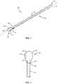
- FIG. 1is a perspective view of a component of a surgical system, in accordance with the present principles of the present disclosure
- FIG. 2is an enlarged top view of one end of the component shown in FIG. 1 ;
- FIG. 3is a side view of the component shown in FIG. 1 ;
- FIG. 4is an end view of the component shown in FIG. 1 ;
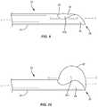
- FIG. 5is a side, cross sectional view of a component of the surgical system, in accordance with the present principles of the present disclosure
- FIG. 6is a side, cross sectional view of the component shown in FIG. 5 ;
- FIG. 7is a side, cross sectional view of a component of the surgical system, in accordance with the present principles of the present disclosure.
- FIG. 8is a side, cross sectional view of the component shown in FIG. 7 ;
- FIG. 9is a side view of the components shown in FIGS. 1 and 5 ;
- FIG. 10is a side view of the components shown in FIGS. 1 and 5 ;
- FIG. 11is a plan view of the components shown in FIGS. 1 and 5 ;
- FIG. 12is a plan view of the components shown in FIGS. 1 and 5 ;
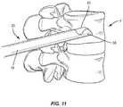
- FIG. 13is a plan view of a surgical site
- FIG. 14is a plan view of a component of the surgical system, in accordance with the present principles of the present disclosure.
- the systemincludes a scoop cannula configured to preferentially direct/inflate an inflatable bone tamp.
- the inflatable bone tampis positioned within the scoop cannula such that the scoop of the scoop cannula is positioned under a balloon of the inflatable bone tamp to provide a backstop for the balloon to inflate against.
- the scoopis configured to direct the balloon to a specific area of a patient's anatomy, such as, for example, a vertebral body.
- the scoopmay be configured to position the balloon adjacent to an end plate or a soft region of bone.
- the scoop cannulacomprises a shape memory material. In some embodiments, the scoop cannula comprises a superelastic material. In some embodiments, the scoop cannula comprises super-elastic Nitinol. In some embodiments, the scoop cannula comprises any material that will deform elastically and then return to its original shape to minimize the effects of deformation.
- the scoop cannulacomprises a scoop having wings.
- the wingsare configured to support the balloon on the sides as well as the bottom, to prevent the balloon from rolling over the edge of the scoop. This will help distribute the load against the bone, increasing the lifting force.
- one or all of the components of the surgical systemmay be disposable, peel-pack, pre-packed sterile devices.
- the components of the surgical systemare configured for one time use and are disposed after they are used one time. However, it is contemplated that one or all of the components of the surgical system may be reusable.
- the surgical systemmay be configured as a kit with multiple sized and configured components, including, for example, various scoop cannulas, balloons, etc.
- one or more of the components of the surgical systemare configured to be sterilized.
- the disclosed surgical system, kits and methodsmay be alternatively employed in a surgical treatment with a patient in a prone or supine position, and/or employ various surgical approaches, including anterior, posterior, posterior mid-line, direct lateral, postero-lateral, antero-lateral approaches, etc. in any body region.
- the system, kits and methods of the present disclosuremay also be used on animals, bone models and other non-living substrates, such as, for example, in training, testing and demonstration.
- Rangesmay be expressed herein as from “about” or “approximately” one particular value and/or to “about” or “approximately” another particular value. When such a range is expressed, another embodiment includes from the one particular value and/or to the other particular value. Similarly, when values are expressed as approximations, by use of the antecedent “about,” it will be understood that the particular value forms another embodiment. It is also understood that all spatial references, such as, for example, horizontal, vertical, top, upper, lower, bottom, left and right, are for illustrative purposes only and can be varied within the scope of the disclosure. For example, the references “upper” and “lower” are relative and used only in the context to the other, and are not necessarily “superior” and “inferior”.
- treating or “treatment” of a disease or conditionrefers to performing a procedure to alleviate signs or symptoms of the disease or condition. Alleviation can occur prior to signs or symptoms of the disease or condition appearing, as well as after their appearance.
- treating or treatmentincludes preventing or prevention of disease or undesirable condition (e.g., preventing the disease from occurring in a patient, who may be predisposed to the disease but has not yet been diagnosed as having it).
- treating or treatmentdoes not require complete alleviation of signs or symptoms, does not require a cure, and specifically includes procedures that have only a marginal effect on the patient.
- Treatmentcan include inhibiting the disease, e.g., arresting its development, or relieving the disease, e.g., causing regression of the disease.
- treatmentcan include reducing acute or chronic inflammation; alleviating pain and mitigating and inducing re-growth of new ligament, bone and other tissues; as an adjunct in surgery; and/or any repair procedure.
- tissueincludes soft tissue, ligaments, tendons, cartilage and/or bone unless specifically referred to otherwise.
- FIGS. 1-14there are illustrated components of a surgical system 20 in accordance with the principles of the present disclosure.
- the components of surgical system 20can be fabricated from biologically acceptable materials suitable for medical applications, including metals, synthetic polymers, ceramics and bone material and/or their composites, depending on the particular application and/or preference of a medical practitioner.
- the components of surgical system 20individually or collectively, can be fabricated from materials such as stainless steel alloys, commercially pure titanium, titanium alloys, Grade 5 titanium, super-elastic titanium alloys, cobalt-chrome alloys, stainless steel alloys, superelastic metallic alloys (e.g., Nitinol, super elasto-plastic metals, such as GUM METAL® manufactured by Toyota Material Incorporated of Japan), ceramics and composites thereof such as calcium phosphate (e.g., SKELITETM manufactured by Biologix Inc.), thermoplastics such as polyaryletherketone (PAEK) including polyetheretherketone (PEEK), polyetherketoneketone (PEKK) and polyetherketone (PEK), carbon-PEEK composites, PEEK-
- Various components of surgical system 20may have material composites, including the above materials, to achieve various desired characteristics such as strength, rigidity, elasticity, compliance, biomechanical performance, durability and radiolucency or imaging preference.
- the components of surgical system 20individually or collectively, may also be fabricated from a heterogeneous material such as a combination of two or more of the above-described materials.
- the components of surgical system 20may be monolithically formed, integrally connected or include fastening elements and/or instruments, as described herein.
- Surgical system 20includes a scoop cannula, such as, for example, kyphoplasty cannula 22 .
- Cannula 22includes a shaft 24 that extends along a longitudinal axis L between a first end surface 26 and an opposite second end surface 28 .
- Shaft 24comprises an inner surface 30 defining a lumen 32 .
- Lumen 32is coaxial with axis L and extends the entire length of shaft 24 .
- Lumen 32has a circular cross-sectional configuration and a uniform diameter along the entire length of lumen 32 .
- lumen 32may have various cross section configurations, such as, for example, oval, oblong, triangular, rectangular, square, polygonal, irregular, uniform, non-uniform, variable, tubular and/or tapered. In some embodiments, lumen 32 may be disposed at alternate orientations, relative to axis L, such as, for example, transverse and/or other angular orientations such as acute or obtuse, co-axial and/or may be offset or staggered.
- Shaft 24comprises a first opening 34 that extends through end surface 26 and a second opening 36 that extends through end surface 28 . Openings 34 , 36 are each in communication with lumen 32 .
- Cannula 22includes a scoop 38 extending from end surface 28 along axis L such that scoop 38 faces away from end surface 26 .
- Scoop 38includes an outer surface 38 a that is continuous with an outer surface 24 a of shaft 24 , as best shown in FIG. 3 . That is, there are no gaps or recesses between outer surface 24 a and outer surface 38 a such that outer surface 24 a smoothly transitions into outer surface 38 a .
- outer surface 38 aextends parallel to outer surface 24 a and/or axis L along an entire length of scoop 38 .
- outer surface 38 amay be disposed at alternate orientations, relative to outer surface 24 a and/or axis L, such as, for example, transverse, perpendicular and/or other angular orientations such as acute or obtuse, co-axial and/or may be offset or staggered.
- Scoop 38includes an arcuate surface 40 that is continuous with inner surface 30 of shaft 24 . That is, there are no gaps or recesses between inner surface 30 and arcuate surface 40 such that inner surface 30 smoothly transitions into arcuate surface 40 .
- Arcuate surface 40is configured to support a bottom surface of a balloon as the balloon is inflated to provide a backstop for the balloon to inflate against, as discussed herein.
- arcuate surface 40is concavely curved from a first side 40 a of arcuate surface 40 to a second side 40 b of arcuate surface.
- arcuate surface 40is continuously curved from first side 40 a of arcuate surface 40 to second side 40 b of arcuate surface.
- arcuate surface 40has a continuous radius of curvature from first side 40 a of arcuate surface 40 to second side 40 b of arcuate surface. In some embodiments, arcuate surface 40 has a radius of curvature from first side 40 a of arcuate surface 40 to second side 40 b of arcuate surface that is greater than the radius of curvature of inner surface 30 of shaft 24 .
- Scoop 38includes a first wing 42 extending outwardly from first side 40 a of arcuate surface 40 and a second wing 44 extending outwardly from second side 40 b of arcuate surface 40 .
- Wings 42 , 44are each configured to support a side surface of a balloon as the balloon is inflated to prevent the balloon from rolling over scoop 38 as the balloon is inflated, as discussed herein.
- Wings 42 , 44are each deflectable relative to arcuate surface 40 .
- wings 42 , 44may deflect relative to arcuate surface 40 as the balloon is inflated.
- shaft 24 and/or scoop 38are made from a shape memory material. In some embodiments, shaft 24 and/or scoop 38 are made from a superelastic material.
- shaft 24 and/or scoop 38are made from super-elastic Nitinol.
- shaft 24 and/or scoop 38are made from a material that will deform elastically and then return to its original shape to minimize the effects of deformation.
- shaft 24 and/or scoop 38are made from super-elastic Nitinol such that wings 42 , 44 will deflect relative to arcuate surface 40 when the balloon is inflated and then return to their original shape after the balloon is deflated.
- Wing 42has an inner surface 42 a that is continuous with arcuate surface 40 and wing 44 has an inner surface 44 a that is continuous with arcuate surface 40 , as best shown in FIG. 4 .
- Surface 42 ais concavely curved from an end surface 46 of wing 42 to end 40 a of arcuate surface 40 and surface 44 a is concavely curved from an end surface 48 of wing 44 to end 40 b of arcuate surface 40 .
- surface 42 ais continuously curved from an end surface 46 of wing 42 to end 40 a of arcuate surface 40 and surface 44 a is continuously curved from an end surface 48 of wing 44 to end 40 b of arcuate surface 40 .
- surface 42 ahas a continuous radius of curvature from an end surface 46 of wing 42 to end 40 a of arcuate surface 40 and surface 44 a has a continuous radius of curvature from an end surface 48 of wing 44 to end 40 b of arcuate surface 40 .
- surfaces 42 a , 44 aeach have a radius of curvature that is equal to the radius of curvature of arcuate surface 40 .
- surfaces 42 a , 44 aeach have a radius of curvature that is less than the radius of curvature of arcuate surface 40 .
- Surfaces 40 , 42 a , 44 adefine a concave surface 50 that extends continuously from end surface 46 to end surface 48 .
- surface 50is continuously curved from end surface 46 to end surface 48 .
- surface 50has a continuous radius of curvature from end surface 46 to end surface 48 .
- surface 50has a radius of curvature that is greater than the radius of curvature of inner surface 30 of shaft 24 .
- the radius of curvature of surface 50is at least about 2 ⁇ greater than the radius of curvature of inner surface 30 of shaft 24 .
- the radius of curvature of surface 50is at least about 5 ⁇ greater than the radius of curvature of inner surface 30 of shaft 24 .
- the radius of curvature of surface 50is at least about 10 ⁇ greater than the radius of curvature of inner surface 30 of shaft 24 .
- Scoop 38has a width w 1 that is defined by the distance from end surface 46 to end surface 48 and shaft 24 has a width w 2 , as shown in FIG. 4 .
- Width w 1is greater than width w 2 .
- width w 1is about 1.5 ⁇ greater than width w 2 .
- width w 1is about 2 ⁇ greater than width w 2 .
- width w 1is about 2.5 ⁇ greater than width w 2 .
- width w 1is about 3 ⁇ greater than width w 2 .
- width w 1is about 3.5 ⁇ greater than width w 2 .
- width w 1is about 4 ⁇ greater than width w 2 .
- wings 42 , 44each have an undulating configuration, as shown in FIG. 3 .
- end surfaces 46 , 48may each include a concave portion 52 that extends from end surface 28 of shaft 24 and a convex portion 54 between concave portion 52 and a tip 56 of scoop 38 .
- Concave portion 52is continuously with end surface 28 and convex portion 54 is continuous with concave portion 54 .
- System 20includes a balloon catheter, such as, for example, an inflatable bone tamp 58 .
- inflatable bone tamp 58includes an outer tube, such as, for example, a tube 60 and a balloon 62 that is coupled to an end of tube 60 .
- An inflation materialsuch as, for example, air, saline, or a contrast solution may be delivered through tube 60 and into balloon 62 to move balloon 62 from an uninflated orientation shown in FIG. 5 to an inflated orientation shown in FIG. 6 .
- inflatable bone tamp 58includes an inner tube, such as, for example a tube 64 positioned within tube 60 .
- a first end of balloon 62is coupled to an end of tube 60 .
- an inflation materialsuch as, for example, air, saline, or a contrast solution may be delivered through the space between tube 60 and tube 64 and into balloon 62 to move balloon 62 from an uninflated orientation shown in FIG. 7 to an inflated orientation shown in FIG. 8 .
- tube 64includes one or a plurality of apertures 66 such that an inflation material, such as, for example, air, saline, or a contrast solution may be delivered through tube 64 and into balloon 62 through apertures 66 to move balloon 62 from an uninflated orientation shown in FIG. 7 to an inflated orientation shown in FIG. 8 .
- balloon 62is configured to expand radially about a longitudinal axis L 1 defined by tube 60 , as shown in FIGS. 6 and 8 .
- balloon 62may configured to expand in only one direction.
- balloon 62may be made such that a top portion of balloon 62 is thicker or comprises a different material than a bottom portion of balloon 62 such that the bottom portion of balloon 62 will expand more than the top portion of balloon 62 when balloon 62 is inflated.
- Inflatable bone tamp 58is configured for insertion into cannula 22 such that tube 60 is positioned within lumen 32 of shaft 24 and balloon 62 is positioned within scoop 38 , as shown in FIGS. 9 and 10 .
- axis Lis coaxial with axis L 1 when inflatable bone tamp 58 is inserted into cannula 22 .
- a bottom surface 62 a of balloon 62directly engages arcuate surface 40
- a first side surface 62 b of balloon 62directly engages inner surface 42 a of wing 42
- an opposite second side surface 62 c of balloon 62directly engages inner surface 44 a of wing 44 .
- arcuate surface 40supports bottom surface 62 a of balloon 62 as balloon 62 is inflated to provide a backstop for balloon 62 to inflate against such that balloon 62 expands away from arcuate surface 40 .
- a centerline C of balloon 62is offset from axis L when balloon 62 is inflated, as shown in FIG. 10 .
- centerline C of balloon 62may be coaxial with axis L when balloon 62 is uninflated, as shown in FIG. 9 .
- Wing 42supports side surface 62 b of balloon 62 and wing 44 supports side surface 62 c of balloon as balloon 62 moves from the uninflated orientation to the inflated orientation to prevent balloon 62 from rolling over scoop 38 as balloon 62 is inflated.
- a medical practitionerobtains access to a target location including at least one bony structure, such as, for example, a fractured vertebra V, in any appropriate manner, such as through incision and retraction of tissue.
- a target locationincluding at least one bony structure, such as, for example, a fractured vertebra V
- the surgical system 20may be used in any existing surgical method or technique including open surgery, mini-open surgery, minimally invasive surgery including percutaneous surgical implantation, whereby vertebra V is accessed through a micro-incision, or sleeve that provides a protected passageway to the area. Once access to the surgical site(s) are obtained, the particular surgical procedure is performed for treating the bone disorder.
- scoop 38may be used to direct balloon 62 toward a wall of an endplate E 1 of vertebra V, as shown in FIG. 12 . That is, rather than allow balloon 62 to expand radially about axis L, scoop 38 causes balloon 62 to expand more toward endplate E 1 than toward an endplate E 2 of vertebra V. As discussed herein, scoop 38 helps to distribute the load created by balloon 62 against vertebra V to increase the lifting force of balloon 62 . As balloon 62 moves from the uninflated orientation to the inflated orientation, wings 42 , 44 deflect relative to arcuate surface 40 of scoop 38 , as discussed herein.
- balloon 62As balloon 62 moves from the uninflated orientation to the inflated orientation, balloon 62 creates a void space S within vertebra V. Balloon 62 is moved from the inflated orientation to the uninflated orientation and cannula 22 is removed from vertebra V, leaving void space S, as shown in FIG. 13 . As balloon 62 moves from the inflated orientation to the uninflated orientation, wings 42 , 44 returns to their original shape, as discussed herein.
- System 20includes a second cannula 66 that is inserted into vertebra V such that an end of the cannula is positioned within void space S, as shown in FIG. 14 .
- a material Mmay be delivered through cannula 66 and into void space S to fill all or a portion of void space S with material M.
- material Mis a curable bone filler material, such as, for example, bone cement. Material M then cures within vertebra V to treat the fracture by reducing pain from the fracture, stabilizing vertebra V and/or restoring vertebra V back to its normal height.
- a kit containing one or more components of surgical system 20is provided.
- the kitmay comprise components from any of the embodiments discussed herein.
- the kitcomprises one or more of the inflation materials discussed herein.
- the kitcomprises one or more bone filler materials, such as, for example, material M.
- the kitcomprises a plurality of cannulas, such as, for example, cannulas 22 and/or cannulas 66 having different lengths configured for use with different size patients.
- the kitcomprises a plurality of cannulas, such as, for example, cannulas 22 having scoops 38 with different widths and/or lengths configured for use with different size balloons.
Landscapes
- Health & Medical Sciences (AREA)
- Orthopedic Medicine & Surgery (AREA)
- Surgery (AREA)
- Life Sciences & Earth Sciences (AREA)
- Molecular Biology (AREA)
- Animal Behavior & Ethology (AREA)
- Engineering & Computer Science (AREA)
- Biomedical Technology (AREA)
- Heart & Thoracic Surgery (AREA)
- Medical Informatics (AREA)
- Veterinary Medicine (AREA)
- Nuclear Medicine, Radiotherapy & Molecular Imaging (AREA)
- General Health & Medical Sciences (AREA)
- Public Health (AREA)
- Neurology (AREA)
- Pathology (AREA)
- Physics & Mathematics (AREA)
- Fluid Mechanics (AREA)
- Surgical Instruments (AREA)
- Prostheses (AREA)
Abstract
Description
Claims (20)
Priority Applications (4)
| Application Number | Priority Date | Filing Date | Title |
|---|---|---|---|
| US15/859,816US10888364B2 (en) | 2018-01-02 | 2018-01-02 | Scoop cannula with deflectable wings |
| EP18205897.4AEP3505112B1 (en) | 2018-01-02 | 2018-11-13 | Scoop cannula with deflectable wings |
| CN201811542882.9ACN109984835A (en) | 2018-01-02 | 2018-12-17 | Spoon spoon intubation with the deflectable wing |
| KR1020180169280AKR20190082667A (en) | 2018-01-02 | 2018-12-26 | Scoop cannula with deflectable wings |
Applications Claiming Priority (1)
| Application Number | Priority Date | Filing Date | Title |
|---|---|---|---|
| US15/859,816US10888364B2 (en) | 2018-01-02 | 2018-01-02 | Scoop cannula with deflectable wings |
Publications (2)
| Publication Number | Publication Date |
|---|---|
| US20190201066A1 US20190201066A1 (en) | 2019-07-04 |
| US10888364B2true US10888364B2 (en) | 2021-01-12 |
Family
ID=64308603
Family Applications (1)
| Application Number | Title | Priority Date | Filing Date |
|---|---|---|---|
| US15/859,816Active2038-06-03US10888364B2 (en) | 2018-01-02 | 2018-01-02 | Scoop cannula with deflectable wings |
Country Status (4)
| Country | Link |
|---|---|
| US (1) | US10888364B2 (en) |
| EP (1) | EP3505112B1 (en) |
| KR (1) | KR20190082667A (en) |
| CN (1) | CN109984835A (en) |
Families Citing this family (4)
| Publication number | Priority date | Publication date | Assignee | Title |
|---|---|---|---|---|
| US11109890B2 (en)* | 2018-01-25 | 2021-09-07 | Kyphon Sarl | Vertebral body access cannula with enhanced bending stiffness |
| US11337741B2 (en)* | 2020-05-01 | 2022-05-24 | Sergio Lenchig | Laterally deployed kyphoplasty balloon tamponade |
| US12272247B2 (en)* | 2020-08-24 | 2025-04-08 | Hyundai Motor Company | Method, device and system for allocating a vehicle for a fleet system based on a user group |
| EP4240261A4 (en)* | 2020-11-05 | 2024-12-18 | Heapsi LLC | TOOLS AND PROCEDURES FOR ARTHROSCOPIC SURGERY |
Citations (54)
| Publication number | Priority date | Publication date | Assignee | Title |
|---|---|---|---|---|
| US4207891A (en) | 1978-10-10 | 1980-06-17 | Population Research Incorporated | Dispensing instrument with supported balloon |
| US4630616A (en) | 1984-06-15 | 1986-12-23 | Berkley And Company, Inc. | Bone marrow needle |
| US4795446A (en) | 1986-01-30 | 1989-01-03 | Sherwood Medical Company | Medical tube device |
| US4838282A (en) | 1987-02-26 | 1989-06-13 | Manan Manufacturing Co., Inc. | Bone biopsy needle assembly |
| US5195507A (en)* | 1990-11-06 | 1993-03-23 | Ethicon, Inc. | Endoscopic surgical instrument for displacing tissue or organs |
| US5262296A (en) | 1988-03-30 | 1993-11-16 | Toray Industries, Inc. | Freeze-dried composition containing enzyme-labeled anti-human interferon-β antibody and enzyme immunoassay kit containing the composition |
| US5295980A (en) | 1989-10-30 | 1994-03-22 | Ersek Robert A | Multi-use cannula system |
| US5385151A (en) | 1992-09-09 | 1995-01-31 | Symbiosis Corporation | Coaxial bone marrow biopsy needle assembly |
| US5501654A (en) | 1993-07-15 | 1996-03-26 | Ethicon, Inc. | Endoscopic instrument having articulating element |
| US5531722A (en) | 1994-11-21 | 1996-07-02 | Van Hale; Gregory L. | Aspiration unit |
| US5807277A (en) | 1995-12-15 | 1998-09-15 | Swaim; William R. | Biopsy hand tool for capturing tissue sample |
| US5876383A (en) | 1997-09-30 | 1999-03-02 | Grooters; Robert K. | Cannula |
| US6186967B1 (en) | 1997-12-18 | 2001-02-13 | Frank Messina | Elevation support for a limb |
| US6447525B2 (en) | 1999-08-19 | 2002-09-10 | Fox Hollow Technologies, Inc. | Apparatus and methods for removing material from a body lumen |
| US6494868B2 (en) | 2000-04-27 | 2002-12-17 | Roger E. Amar | Set of cannulae for tissue injections in the human face |
| US6575919B1 (en) | 1999-10-19 | 2003-06-10 | Kyphon Inc. | Hand-held instruments that access interior body regions |
| US6755793B2 (en) | 2000-07-29 | 2004-06-29 | Worldwide Medical Technologies | Bone marrow extraction tool |
| US6875183B2 (en) | 1999-03-19 | 2005-04-05 | Paul Laurence Cervi | Biopsy needle |
| US6949108B2 (en) | 2001-02-28 | 2005-09-27 | Hol-Med Corporation | Curette with detachable tip |
| US20050273076A1 (en) | 2004-06-07 | 2005-12-08 | C.R. Bard, Inc. | Subcutaneous infusion devices |
| US6979318B1 (en) | 2002-10-07 | 2005-12-27 | Lemaitre Vascular, Inc. | Catheter introducer |
| US7044954B2 (en) | 1994-01-26 | 2006-05-16 | Kyphon Inc. | Method for treating a vertebral body |
| EP1708621A2 (en) | 2004-01-26 | 2006-10-11 | Vidacare Corporation | Manual interosseous device |
| US20070010845A1 (en) | 2005-07-08 | 2007-01-11 | Gorman Gong | Directionally controlled expandable device and methods for use |
| EP1748722A2 (en) | 2004-01-29 | 2007-02-07 | Cannuflow, Inc. | Atraumatic arthroscopic instrument sheath |
| EP1703923B1 (en) | 2003-12-23 | 2008-05-07 | Cytyc Corporation | Medical instrument for accessing a breast duct for performing a medical procedure |
| US7500947B2 (en) | 2004-01-29 | 2009-03-10 | Cannonflow, Inc. | Atraumatic arthroscopic instrument sheath |
| US7510549B2 (en) | 2003-04-03 | 2009-03-31 | Indevus Pharmaceutical, Inc. | Method of inserting an object under the skin |
| US20090216238A1 (en) | 2008-02-27 | 2009-08-27 | Stark John G | Tools for performing less invasive orthopedic joint procedures |
| US7691060B2 (en) | 2003-10-10 | 2010-04-06 | Angelsen Bjoern A J | Probe for 3-dimensional scanning and focusing of an ultrasound beam |
| US7708713B2 (en) | 2004-06-29 | 2010-05-04 | Applied Medical Resources Corporation | Insufflating optical surgical instrument |
| US7713273B2 (en) | 2005-11-18 | 2010-05-11 | Carefusion 2200, Inc. | Device, system and method for delivering a curable material into bone |
| US20100185116A1 (en) | 2009-01-19 | 2010-07-22 | King Saud University | Punch biopsy device |
| US20100198140A1 (en) | 2009-02-05 | 2010-08-05 | Kevin Jon Lawson | Percutaneous tools and bone pellets for vertebral body reconstruction |
| US20100222745A1 (en) | 2009-03-02 | 2010-09-02 | Becton, Dickinson And Company | Bi-directionally engageable cannula crimp feature |
| US7892216B2 (en) | 2006-02-07 | 2011-02-22 | Icu Medical, Inc. | Infusion set |
| US7938794B2 (en) | 2007-05-04 | 2011-05-10 | Sscor, Inc. | Airway suction spoon |
| US20110202065A1 (en) | 2008-10-17 | 2011-08-18 | St. Marianna University School Of Medicine | Bone cement injection needle |
| US20110202062A1 (en) | 2010-02-18 | 2011-08-18 | O'halloran Damien | Methods and Apparatus For Treating Vertebral Fractures |
| US8052641B2 (en) | 2006-06-30 | 2011-11-08 | Nipro Corporation | Indwelling needle with wings |
| US8088081B2 (en) | 2004-05-11 | 2012-01-03 | Inrad, Inc. | Core biopsy device |
| US20120010624A1 (en) | 2009-12-07 | 2012-01-12 | O'halloran Damien | Methods and Apparatus For Treating Vertebral Fractures |
| US8167899B2 (en) | 2006-05-04 | 2012-05-01 | Warsaw Orthopedic, Inc. | Retractable stylet and cannula combination |
| US20120143206A1 (en) | 2009-06-25 | 2012-06-07 | Wallace Michael P | Surgical tools for treatment of spinal stenosis |
| US8251950B2 (en) | 2005-08-08 | 2012-08-28 | Smiths Medical Asd, Inc. | Needle guard clip with heel |
| US8257322B2 (en) | 2010-06-02 | 2012-09-04 | Smiths Medical Asd, Inc. | Tip protector for a safety catheter |
| US8323251B2 (en) | 2008-01-14 | 2012-12-04 | Fenwal, Inc. | Phlebotomy needle assembly and frangible cover |
| US20120330241A1 (en) | 2006-05-04 | 2012-12-27 | Haddock Sean M | Method for using retractable stylet and cannula combination to form an opening in bone |
| US20130013007A1 (en)* | 2011-07-05 | 2013-01-10 | Kyphon Sarl | Combination directional and non-directional bone tamp |
| US8702743B2 (en)* | 2006-10-25 | 2014-04-22 | Koninklijke Philips N.V. | Instrument with an inflatable balloon |
| US8709362B2 (en)* | 2004-06-07 | 2014-04-29 | Investigen, Inc. | Laboratory spatula |
| US20140214085A1 (en) | 2013-01-25 | 2014-07-31 | Kyphon Sarl | Expandable device and methods of use |
| US20140235997A1 (en)* | 2013-02-21 | 2014-08-21 | Kyphon Sarl | Cannula with image markers to indicate expandable device size |
| US20150127104A1 (en)* | 2012-05-03 | 2015-05-07 | ULTIMATE JOINT LTD. a corporation | In-situ formation of a joint replacement prosthesis |
Family Cites Families (14)
| Publication number | Priority date | Publication date | Assignee | Title |
|---|---|---|---|---|
| CA2131141A1 (en)* | 1993-09-24 | 1995-03-25 | James A. Boucher | Ligament graft protection apparatus and method |
| US7815649B2 (en)* | 2000-04-07 | 2010-10-19 | Kyphon SÀRL | Insertion devices and method of use |
| WO2002034148A2 (en)* | 2000-10-25 | 2002-05-02 | Kyphon Inc. | Systems and methods for reducing fractured bone using a fracture reduction cannula |
| US20090299373A1 (en)* | 2008-05-30 | 2009-12-03 | Cook Incorporated | Kyphoplasty banded balloon catheter |
| US9078655B2 (en)* | 2009-04-17 | 2015-07-14 | Domain Surgical, Inc. | Heated balloon catheter |
| RU2437631C1 (en)* | 2010-08-23 | 2011-12-27 | Александр Ильич Тома | Apparatus of vertebra balloon kyphoplasty (versions) |
| US9387030B2 (en)* | 2013-01-07 | 2016-07-12 | Kyphon SÀRL | Catheter with integrated cement delivery balloon |
| US9364341B2 (en)* | 2014-01-09 | 2016-06-14 | Warsaw Orthopedic, Inc. | Spinal implant system and method |
| CN106163436B (en)* | 2014-03-10 | 2020-03-17 | 泰克里斯公司 | Device for removing bone cement from a bone cavity |
| US10123810B2 (en)* | 2015-09-02 | 2018-11-13 | Life Spine, Inc. | Medical instrument set and method of use for treating bony aberrations of the calcaneus |
| US20170164978A1 (en)* | 2015-12-09 | 2017-06-15 | Laurian Mark Dean | Delivery Device and Method For Vertebroplasty and Kyphoplasty Procedures |
| EP3402383B1 (en)* | 2016-01-15 | 2020-04-22 | Farbes Medical, LLC | Imaging competent, bi-directionally articulable endotracheal tubes |
| US10493247B2 (en)* | 2016-03-15 | 2019-12-03 | Medtronic Holding Company Sàrl | Devices for delivering a chemical denervation agent and methods of use |
| CN106422038A (en)* | 2016-09-28 | 2017-02-22 | 上海凯利泰医疗科技股份有限公司 | Vertebral body expansion balloon catheter |
- 2018
- 2018-01-02USUS15/859,816patent/US10888364B2/enactiveActive
- 2018-11-13EPEP18205897.4Apatent/EP3505112B1/enactiveActive
- 2018-12-17CNCN201811542882.9Apatent/CN109984835A/enactivePending
- 2018-12-26KRKR1020180169280Apatent/KR20190082667A/enactivePending
Patent Citations (54)
| Publication number | Priority date | Publication date | Assignee | Title |
|---|---|---|---|---|
| US4207891A (en) | 1978-10-10 | 1980-06-17 | Population Research Incorporated | Dispensing instrument with supported balloon |
| US4630616A (en) | 1984-06-15 | 1986-12-23 | Berkley And Company, Inc. | Bone marrow needle |
| US4795446A (en) | 1986-01-30 | 1989-01-03 | Sherwood Medical Company | Medical tube device |
| US4838282A (en) | 1987-02-26 | 1989-06-13 | Manan Manufacturing Co., Inc. | Bone biopsy needle assembly |
| US5262296A (en) | 1988-03-30 | 1993-11-16 | Toray Industries, Inc. | Freeze-dried composition containing enzyme-labeled anti-human interferon-β antibody and enzyme immunoassay kit containing the composition |
| US5295980A (en) | 1989-10-30 | 1994-03-22 | Ersek Robert A | Multi-use cannula system |
| US5195507A (en)* | 1990-11-06 | 1993-03-23 | Ethicon, Inc. | Endoscopic surgical instrument for displacing tissue or organs |
| US5385151A (en) | 1992-09-09 | 1995-01-31 | Symbiosis Corporation | Coaxial bone marrow biopsy needle assembly |
| US5501654A (en) | 1993-07-15 | 1996-03-26 | Ethicon, Inc. | Endoscopic instrument having articulating element |
| US7044954B2 (en) | 1994-01-26 | 2006-05-16 | Kyphon Inc. | Method for treating a vertebral body |
| US5531722A (en) | 1994-11-21 | 1996-07-02 | Van Hale; Gregory L. | Aspiration unit |
| US5807277A (en) | 1995-12-15 | 1998-09-15 | Swaim; William R. | Biopsy hand tool for capturing tissue sample |
| US5876383A (en) | 1997-09-30 | 1999-03-02 | Grooters; Robert K. | Cannula |
| US6186967B1 (en) | 1997-12-18 | 2001-02-13 | Frank Messina | Elevation support for a limb |
| US6875183B2 (en) | 1999-03-19 | 2005-04-05 | Paul Laurence Cervi | Biopsy needle |
| US6447525B2 (en) | 1999-08-19 | 2002-09-10 | Fox Hollow Technologies, Inc. | Apparatus and methods for removing material from a body lumen |
| US6575919B1 (en) | 1999-10-19 | 2003-06-10 | Kyphon Inc. | Hand-held instruments that access interior body regions |
| US6494868B2 (en) | 2000-04-27 | 2002-12-17 | Roger E. Amar | Set of cannulae for tissue injections in the human face |
| US6755793B2 (en) | 2000-07-29 | 2004-06-29 | Worldwide Medical Technologies | Bone marrow extraction tool |
| US6949108B2 (en) | 2001-02-28 | 2005-09-27 | Hol-Med Corporation | Curette with detachable tip |
| US6979318B1 (en) | 2002-10-07 | 2005-12-27 | Lemaitre Vascular, Inc. | Catheter introducer |
| US7510549B2 (en) | 2003-04-03 | 2009-03-31 | Indevus Pharmaceutical, Inc. | Method of inserting an object under the skin |
| US7691060B2 (en) | 2003-10-10 | 2010-04-06 | Angelsen Bjoern A J | Probe for 3-dimensional scanning and focusing of an ultrasound beam |
| EP1703923B1 (en) | 2003-12-23 | 2008-05-07 | Cytyc Corporation | Medical instrument for accessing a breast duct for performing a medical procedure |
| EP1708621A2 (en) | 2004-01-26 | 2006-10-11 | Vidacare Corporation | Manual interosseous device |
| US7500947B2 (en) | 2004-01-29 | 2009-03-10 | Cannonflow, Inc. | Atraumatic arthroscopic instrument sheath |
| EP1748722A2 (en) | 2004-01-29 | 2007-02-07 | Cannuflow, Inc. | Atraumatic arthroscopic instrument sheath |
| US8088081B2 (en) | 2004-05-11 | 2012-01-03 | Inrad, Inc. | Core biopsy device |
| US8709362B2 (en)* | 2004-06-07 | 2014-04-29 | Investigen, Inc. | Laboratory spatula |
| US20050273076A1 (en) | 2004-06-07 | 2005-12-08 | C.R. Bard, Inc. | Subcutaneous infusion devices |
| US7708713B2 (en) | 2004-06-29 | 2010-05-04 | Applied Medical Resources Corporation | Insufflating optical surgical instrument |
| US20070010845A1 (en) | 2005-07-08 | 2007-01-11 | Gorman Gong | Directionally controlled expandable device and methods for use |
| US8251950B2 (en) | 2005-08-08 | 2012-08-28 | Smiths Medical Asd, Inc. | Needle guard clip with heel |
| US7713273B2 (en) | 2005-11-18 | 2010-05-11 | Carefusion 2200, Inc. | Device, system and method for delivering a curable material into bone |
| US7892216B2 (en) | 2006-02-07 | 2011-02-22 | Icu Medical, Inc. | Infusion set |
| US8167899B2 (en) | 2006-05-04 | 2012-05-01 | Warsaw Orthopedic, Inc. | Retractable stylet and cannula combination |
| US20120330241A1 (en) | 2006-05-04 | 2012-12-27 | Haddock Sean M | Method for using retractable stylet and cannula combination to form an opening in bone |
| US8052641B2 (en) | 2006-06-30 | 2011-11-08 | Nipro Corporation | Indwelling needle with wings |
| US8702743B2 (en)* | 2006-10-25 | 2014-04-22 | Koninklijke Philips N.V. | Instrument with an inflatable balloon |
| US7938794B2 (en) | 2007-05-04 | 2011-05-10 | Sscor, Inc. | Airway suction spoon |
| US8323251B2 (en) | 2008-01-14 | 2012-12-04 | Fenwal, Inc. | Phlebotomy needle assembly and frangible cover |
| US20090216238A1 (en) | 2008-02-27 | 2009-08-27 | Stark John G | Tools for performing less invasive orthopedic joint procedures |
| US20110202065A1 (en) | 2008-10-17 | 2011-08-18 | St. Marianna University School Of Medicine | Bone cement injection needle |
| US20100185116A1 (en) | 2009-01-19 | 2010-07-22 | King Saud University | Punch biopsy device |
| US20100198140A1 (en) | 2009-02-05 | 2010-08-05 | Kevin Jon Lawson | Percutaneous tools and bone pellets for vertebral body reconstruction |
| US20100222745A1 (en) | 2009-03-02 | 2010-09-02 | Becton, Dickinson And Company | Bi-directionally engageable cannula crimp feature |
| US20120143206A1 (en) | 2009-06-25 | 2012-06-07 | Wallace Michael P | Surgical tools for treatment of spinal stenosis |
| US20120010624A1 (en) | 2009-12-07 | 2012-01-12 | O'halloran Damien | Methods and Apparatus For Treating Vertebral Fractures |
| US20110202062A1 (en) | 2010-02-18 | 2011-08-18 | O'halloran Damien | Methods and Apparatus For Treating Vertebral Fractures |
| US8257322B2 (en) | 2010-06-02 | 2012-09-04 | Smiths Medical Asd, Inc. | Tip protector for a safety catheter |
| US20130013007A1 (en)* | 2011-07-05 | 2013-01-10 | Kyphon Sarl | Combination directional and non-directional bone tamp |
| US20150127104A1 (en)* | 2012-05-03 | 2015-05-07 | ULTIMATE JOINT LTD. a corporation | In-situ formation of a joint replacement prosthesis |
| US20140214085A1 (en) | 2013-01-25 | 2014-07-31 | Kyphon Sarl | Expandable device and methods of use |
| US20140235997A1 (en)* | 2013-02-21 | 2014-08-21 | Kyphon Sarl | Cannula with image markers to indicate expandable device size |
Also Published As
| Publication number | Publication date |
|---|---|
| KR20190082667A (en) | 2019-07-10 |
| US20190201066A1 (en) | 2019-07-04 |
| CN109984835A (en) | 2019-07-09 |
| EP3505112A1 (en) | 2019-07-03 |
| EP3505112B1 (en) | 2023-04-19 |
Similar Documents
| Publication | Publication Date | Title |
|---|---|---|
| US11771485B2 (en) | Device for performing a surgical procedure and method | |
| US9668796B2 (en) | Low cost inflatable bone tamp | |
| US9936993B2 (en) | Expandable device and methods of use | |
| US10888364B2 (en) | Scoop cannula with deflectable wings | |
| US9713534B2 (en) | Surgical system and methods of use | |
| US12064157B2 (en) | Method of performing a balloon kyphoplasty procedure using a scoop cannula | |
| US10478240B2 (en) | Device for performing a surgical procedure and methods of use | |
| US9597137B2 (en) | Catheter with integrated cement delivery balloon | |
| EP3520725B1 (en) | Vertebral body access cannula with enhanced bending stiffness | |
| US9204915B2 (en) | Device for performing a surgical procedure and method | |
| US20170281251A1 (en) | Surgical system and method | |
| US20160278822A1 (en) | Surgical injection system and method | |
| US10070902B2 (en) | Spinal implant system and method | |
| US20160354130A1 (en) | Bone tamp and method of use | |
| US20140277211A1 (en) | Device for performing a surgical procedure and method |
Legal Events
| Date | Code | Title | Description |
|---|---|---|---|
| FEPP | Fee payment procedure | Free format text:ENTITY STATUS SET TO UNDISCOUNTED (ORIGINAL EVENT CODE: BIG.); ENTITY STATUS OF PATENT OWNER: LARGE ENTITY | |
| AS | Assignment | Owner name:KYPHON SARL, SWITZERLAND Free format text:ASSIGNMENT OF ASSIGNORS INTEREST;ASSIGNORS:SASAKI, NEIL;CHAN, HESTER;GOSHAYESHGAR, MOJAN;REEL/FRAME:044584/0449 Effective date:20171221 | |
| STPP | Information on status: patent application and granting procedure in general | Free format text:DOCKETED NEW CASE - READY FOR EXAMINATION | |
| AS | Assignment | Owner name:MEDTRONIC HOLDING COMPANY SARL, SWITZERLAND Free format text:ASSIGNMENT OF ASSIGNORS INTEREST;ASSIGNOR:KYPHON SARL;REEL/FRAME:046225/0001 Effective date:20180426 | |
| STPP | Information on status: patent application and granting procedure in general | Free format text:NON FINAL ACTION MAILED | |
| STPP | Information on status: patent application and granting procedure in general | Free format text:FINAL REJECTION MAILED | |
| STPP | Information on status: patent application and granting procedure in general | Free format text:RESPONSE AFTER FINAL ACTION FORWARDED TO EXAMINER | |
| STPP | Information on status: patent application and granting procedure in general | Free format text:ADVISORY ACTION MAILED | |
| STPP | Information on status: patent application and granting procedure in general | Free format text:DOCKETED NEW CASE - READY FOR EXAMINATION | |
| STPP | Information on status: patent application and granting procedure in general | Free format text:NON FINAL ACTION MAILED | |
| STPP | Information on status: patent application and granting procedure in general | Free format text:RESPONSE TO NON-FINAL OFFICE ACTION ENTERED AND FORWARDED TO EXAMINER | |
| STPP | Information on status: patent application and granting procedure in general | Free format text:FINAL REJECTION MAILED | |
| STPP | Information on status: patent application and granting procedure in general | Free format text:RESPONSE AFTER FINAL ACTION FORWARDED TO EXAMINER | |
| STPP | Information on status: patent application and granting procedure in general | Free format text:NOTICE OF ALLOWANCE MAILED -- APPLICATION RECEIVED IN OFFICE OF PUBLICATIONS | |
| STPP | Information on status: patent application and granting procedure in general | Free format text:PUBLICATIONS -- ISSUE FEE PAYMENT VERIFIED | |
| STCF | Information on status: patent grant | Free format text:PATENTED CASE | |
| MAFP | Maintenance fee payment | Free format text:PAYMENT OF MAINTENANCE FEE, 4TH YEAR, LARGE ENTITY (ORIGINAL EVENT CODE: M1551); ENTITY STATUS OF PATENT OWNER: LARGE ENTITY Year of fee payment:4 | |
| AS | Assignment | Owner name:MEDTRONIC EUROPE SARL, SWITZERLAND Free format text:MERGER;ASSIGNOR:MEDTRONIC HOLDING COMPANY SARL;REEL/FRAME:070809/0661 Effective date:20241018 |