US10888173B2 - Air controller with vibration isolators - Google Patents
Air controller with vibration isolatorsDownload PDFInfo
- Publication number
- US10888173B2 US10888173B2US15/337,484US201615337484AUS10888173B2US 10888173 B2US10888173 B2US 10888173B2US 201615337484 AUS201615337484 AUS 201615337484AUS 10888173 B2US10888173 B2US 10888173B2
- Authority
- US
- United States
- Prior art keywords
- post
- air
- housing
- flow control
- supporting structure
- Prior art date
- Legal status (The legal status is an assumption and is not a legal conclusion. Google has not performed a legal analysis and makes no representation as to the accuracy of the status listed.)
- Active, expires
Links
Images


Classifications
- A—HUMAN NECESSITIES
- A47—FURNITURE; DOMESTIC ARTICLES OR APPLIANCES; COFFEE MILLS; SPICE MILLS; SUCTION CLEANERS IN GENERAL
- A47C—CHAIRS; SOFAS; BEDS
- A47C27/00—Spring, stuffed or fluid mattresses or cushions specially adapted for chairs, beds or sofas
- A47C27/08—Fluid mattresses
- A47C27/081—Fluid mattresses of pneumatic type
- A47C27/083—Fluid mattresses of pneumatic type with pressure control, e.g. with pressure sensors
- A—HUMAN NECESSITIES
- A47—FURNITURE; DOMESTIC ARTICLES OR APPLIANCES; COFFEE MILLS; SPICE MILLS; SUCTION CLEANERS IN GENERAL
- A47C—CHAIRS; SOFAS; BEDS
- A47C27/00—Spring, stuffed or fluid mattresses or cushions specially adapted for chairs, beds or sofas
- A47C27/08—Fluid mattresses
- A47C27/081—Fluid mattresses of pneumatic type
- A47C27/082—Fluid mattresses of pneumatic type with non-manual inflation, e.g. with electric pumps
- A—HUMAN NECESSITIES
- A47—FURNITURE; DOMESTIC ARTICLES OR APPLIANCES; COFFEE MILLS; SPICE MILLS; SUCTION CLEANERS IN GENERAL
- A47C—CHAIRS; SOFAS; BEDS
- A47C27/00—Spring, stuffed or fluid mattresses or cushions specially adapted for chairs, beds or sofas
- A47C27/08—Fluid mattresses
- A47C27/10—Fluid mattresses with two or more independently-fillable chambers
- F—MECHANICAL ENGINEERING; LIGHTING; HEATING; WEAPONS; BLASTING
- F16—ENGINEERING ELEMENTS AND UNITS; GENERAL MEASURES FOR PRODUCING AND MAINTAINING EFFECTIVE FUNCTIONING OF MACHINES OR INSTALLATIONS; THERMAL INSULATION IN GENERAL
- F16F—SPRINGS; SHOCK-ABSORBERS; MEANS FOR DAMPING VIBRATION
- F16F1/00—Springs
- F16F1/36—Springs made of rubber or other material having high internal friction, e.g. thermoplastic elastomers
- F16F1/373—Springs made of rubber or other material having high internal friction, e.g. thermoplastic elastomers characterised by having a particular shape
- F16F1/376—Springs made of rubber or other material having high internal friction, e.g. thermoplastic elastomers characterised by having a particular shape having projections, studs, serrations or the like on at least one surface
- F—MECHANICAL ENGINEERING; LIGHTING; HEATING; WEAPONS; BLASTING
- F16—ENGINEERING ELEMENTS AND UNITS; GENERAL MEASURES FOR PRODUCING AND MAINTAINING EFFECTIVE FUNCTIONING OF MACHINES OR INSTALLATIONS; THERMAL INSULATION IN GENERAL
- F16F—SPRINGS; SHOCK-ABSORBERS; MEANS FOR DAMPING VIBRATION
- F16F15/00—Suppression of vibrations in systems; Means or arrangements for avoiding or reducing out-of-balance forces, e.g. due to motion
- F16F15/02—Suppression of vibrations of non-rotating, e.g. reciprocating systems; Suppression of vibrations of rotating systems by use of members not moving with the rotating systems
- F16F15/04—Suppression of vibrations of non-rotating, e.g. reciprocating systems; Suppression of vibrations of rotating systems by use of members not moving with the rotating systems using elastic means
- F16F15/08—Suppression of vibrations of non-rotating, e.g. reciprocating systems; Suppression of vibrations of rotating systems by use of members not moving with the rotating systems using elastic means with rubber springs ; with springs made of rubber and metal
- F—MECHANICAL ENGINEERING; LIGHTING; HEATING; WEAPONS; BLASTING
- F16—ENGINEERING ELEMENTS AND UNITS; GENERAL MEASURES FOR PRODUCING AND MAINTAINING EFFECTIVE FUNCTIONING OF MACHINES OR INSTALLATIONS; THERMAL INSULATION IN GENERAL
- F16F—SPRINGS; SHOCK-ABSORBERS; MEANS FOR DAMPING VIBRATION
- F16F1/00—Springs
- F16F1/36—Springs made of rubber or other material having high internal friction, e.g. thermoplastic elastomers
- F16F1/373—Springs made of rubber or other material having high internal friction, e.g. thermoplastic elastomers characterised by having a particular shape
- F16F1/3732—Springs made of rubber or other material having high internal friction, e.g. thermoplastic elastomers characterised by having a particular shape having an annular or the like shape, e.g. grommet-type resilient mountings
Definitions
- This inventionrelates to vibration, and more particularly to vibration isolators for use in air controllers of air beds.
- some bedscan have one or more inflatable air chambers.
- Some of such bedscan include an inflation system including a number of mechanical and electrical components.
- some bedscan include one or more pumps with one or more valves for inflating the air chambers.
- Some embodiments of an air controller pump systemcan include one or more of the features and functions disclosed herein. Some embodiments can include vibration isolators for dampening vibration of a flow control assembly to achieve quieter operation.
- the vibration isolatorscan have certain features allowing for ease of assembly and suitable dampening of vibration due to actuation of solenoid valves. This can be desirable, for example, in an air bed system configured for automatically adjusting pressure while a user is asleep, where quiet operation can be particularly desirable.
- an air bed systemcan include a mattress comprising a first inflatable air chamber and an air controller fluidly connected to the first inflatable air chamber of the mattress for inflating and deflating the first inflatable air chamber.
- the air controllercan include an air pump, a flow control assembly fluidly connected between the air pump and the first inflatable air chamber, and first and second supporting structures.
- the flow control assemblyis supported between the first and second supporting structure.
- a plurality of vibration isolatorscan include at least a first vibration isolator positioned between the first supporting structure and the flow control assembly and a second vibration isolator positioned between the second supporting structure and the flow control assembly.
- the air controllerincludes a housing having a housing top and a housing bottom, wherein the first supporting structure is part of the housing top and the second supporting structure is part of the housing bottom, and wherein the vibration isolators prevent contact between the flow control assembly and the housing top and bottom so as to reduce transmission of vibration from the flow control assembly to the housing.
- the flow control assemblycomprises an air manifold and a plurality of valves connected to the air manifold.
- the air manifoldincludes a first vertical post having a first post top and a first post bottom and a second vertical post having a second post top and a second post bottom, wherein the first vibration isolator is positioned between the first post top and the first supporting structure, wherein the second vibration isolator is positioned between the first post bottom and the second supporting structure, wherein a third vibration isolator is positioned between the second post top and the first supporting structure, and wherein a fourth vibration isolator is positioned between the second post bottom and the second supporting structure.
- the plurality of valvesare rigidly mounted to the air manifold along a length of the air manifold between the first vertical post and the second vertical post.
- the valvescomprise solenoid valves rigidly mounted to the air manifold and the air pump comprises a positive displacement pump spaced from the air manifold and connected to the air manifold via a tube.
- the air controllerincludes a housing having a housing top and a housing bottom. The first supporting structure is part of the housing top and the second supporting structure is part of the housing bottom. A threaded fastener extends through holes defined by the housing bottom, the first vibration isolator, the flow control assembly, the second vibration isolator, and the housing top to connect the housing top to the housing bottom and to hold the flow control assembly in place within the housing.
- the vibration isolatorseach comprise a cylindrical portion extending substantially circumferentially about an axis and an annular portion extending substantially radially with respect to the axis and having an inner rim that defines a hole and an outer rim connected to an end of the cylindrical portion.
- the annular portionincludes a first set of projections extending from a first side of the annular portion and a second set of projections extending from a second side of the annular portion, wherein the second side is positioned opposite the first side.
- the first set of projectionseach extend radially from the inner rim to the outer rim and the second set of projections are shaped differently than the first set of projections.
- the second set of projectionsare positioned proximate to and spaced from an inner surface of the cylindrical portion.
- the flow control assemblyincludes a first vertical post having a first post top and a first post bottom.
- the first vibration isolatoris positioned between the first post top and the first supporting structure with the cylindrical portion wrapped around a circumferential portion of the first post top with the second set of projections abutting an end of the first post top, the first set of projections abutting the first supporting structure, and the inner rim abutting the first supporting structure.
- the second vibration isolatoris positioned between the first post bottom and the second supporting structure with the cylindrical portion of the second vibration isolator wrapped around a circumferential portion of the first post bottom, with the second set of projections of the second supporting structure abutting an end of the first post bottom, the first set of projections of the second vibration isolator abutting a printed circuit board, and the inner rim of the second vibration isolator abutting the second supporting structure.
- the flow control assemblyincludes a post having a post end, wherein the first vibration isolator is positioned between the post end and the first supporting structure with the cylindrical portion wrapped around a circumferential portion of the post, with the second set of projections abutting the post end, with the first set of projections abutting the first supporting structure, and with the inner rim abutting the first supporting structure.
- the flow control assemblyincludes a post having a post end, wherein the first vibration isolator is positioned between the post end and the first supporting structure with the cylindrical portion wrapped around a circumferential portion of the post, with the annular portion abutting the post end and the first supporting structure.
- the vibrations isolatorscomprise an elastomer.
- an air controllerin another aspect, includes an air pump, a flow control assembly having an air manifold fluidly connected to the air pump and a plurality of valves mounted to the air manifold, and a housing including a housing top having a first supporting structure and a housing bottom having a second supporting structure.
- the flow control assemblyis supported between the first and second supporting structures.
- a plurality of vibration isolatorsinclude at least a first vibration isolator positioned between the first supporting structure and the flow control assembly and a second vibration isolator positioned between the second supporting structure and the flow control assembly.
- the vibration isolatorseach comprise a cylindrical portion extending substantially circumferentially about an axis and an annular portion extending substantially radially with respect to the axis.
- the annular portionhas an inner rim that defines a hole and an outer rim connected to an end of the cylindrical portion.
- the annular portionincludes a first set of projections extending from a first side of the annular portion and a second set of projections extending from a second side of the annular portion. The second side is positioned opposite the first side.
- an air controllerin another aspect, includes an air pump, a flow control assembly having an air manifold fluidly connected to the air pump and a plurality of valves mounted to the air manifold, a housing, and means for mounting the flow control assembly in the housing and dampening transmission of vibration from the flow control assembly to the housing.
- FIG. 1shows an example air bed system.
- FIG. 2is a block diagram of an example of various components of an air bed system.
- FIG. 3is a perspective view of an air controller for use in an air bed system.
- FIG. 4is a perspective view of the air controller of FIG. 3 with a housing top removed.
- FIG. 5is a top view of the air controller of FIG. 3 with the housing top removed.
- FIG. 6is a side view of the air controller of FIG. 3 with the housing top removed.
- FIG. 7is a perspective bottom view of a housing top.
- FIG. 8is a perspective top view of a housing bottom.
- FIGS. 9A and 9Bare perspective views of a vibration isolator.
- An air controllersuch as for inflatable air beds, can both inflate and deflate air chambers of a mattress. In applications in which the air bed is configured for inflation and/or deflation while a user is sleeping on the air bed, quiet operation can be particularly desirable.
- An air control systemcan include vibration isolators connected to a flow control assembly having one or more valves to dampen vibration of the flow control assembly. This can reduce transmission of vibration from the valves to a housing of the air control system, and consequently, allow the air control system to operate more quietly.
- FIG. 1shows an example air bed system 100 that includes a bed 112 .
- the bed 112includes at least one air chamber 114 (e.g., a first air chamber 114 A and a second air chamber 114 B) surrounded by a resilient border 116 and encapsulated by bed ticking 118 .
- the resilient border 116can comprise any suitable material, such as foam.
- the bed 112can be a two chamber design having first and second fluid chambers, such as the first air chamber 114 A and the second air chamber 114 B.
- the bed 112can include chambers for use with fluids other than air that are suitable for the application.
- the bed 112can include a single air chamber 114 or multiple air chambers 114 .
- the first and second air chambers 114 A and 114 Bcan be in fluid communication with a pump 120 .
- the pump 120can be part of an air controller 124 , which can be in electrical communication with a remote control 122 .
- the air controller 124can include a wired or wireless communications interface for communicating with one or more devices, including the remote control 122 .
- the air controller 124can be configured to operate the pump 120 to cause increases and decreases in the fluid pressure of the first and second air chambers 114 A and 114 B based upon commands input by a user using the remote control 122 .
- the pump 120 and the air controller 124can be integrated into a common housing. In other embodiments, the air controller 124 and the pump 120 can be in separate housings.
- the remote control 122can include a display 126 , an output selecting mechanism 128 , a pressure increase button 129 , and a pressure decrease button 130 .
- the output selecting mechanism 128can allow the user to switch air flow generated by the pump 120 between the first and second air chambers 114 A and 114 B, thus enabling control of multiple air chambers with a single remote control 122 and a single pump 120 .
- the output selecting mechanism 128can by a physical control (e.g., switch or button) or an input control displayed on display 126 .
- separate remote control unitscan be provided for each air chamber and can each include the ability to control multiple air chambers.
- Pressure increase and decrease buttons 129 and 130can allow a user to increase or decrease the pressure, respectively, in the air chamber selected with the output selecting mechanism 128 . Adjusting the pressure within the selected air chamber can cause a corresponding adjustment to the firmness of the respective air chamber.
- the remote control 122can be omitted or modified as appropriate for an application.
- the bed 112can be controlled by a computer, tablet, smart phone, or other device in wired or wireless communication with the bed 112 .
- FIG. 2is a block diagram of an example of various components of an air bed system.
- the air controller 124can include the pump 120 , a power supply 134 , a processor 136 , a memory 137 , a switching mechanism 138 , and an analog to digital (A/D) converter 140 , an air manifold 143 (having valves (e.g., a relief valve 144 , a first control valve 145 A, and a second control valve 145 B)), and one or more pressure transducers 146 .
- the switching mechanism 138can be, for example, a relay or a solid state switch.
- the pump 120can include a motor 142 .
- the pump 120can be fluidly connected to the pump manifold, which is fluidically connected with the first air chamber 114 A and the second air chamber 114 B via a first tube 148 A and a second tube 148 B, respectively.
- the first and second control valves 145 A and 145 Bcan be controlled by switching mechanism 138 , and are operable to regulate the flow of fluid between the pump 120 and first and second air chambers 114 A and 114 B, respectively.
- the pump 120 and the air controller 124can be provided and packaged as a single unit. In some alternative implementations, the pump 120 and the air controller 124 can be provided as physically separate units. In some implementations, the air controller 124 , the pump 120 , or both are integrated within or otherwise contained within a bed frame or bed support structure that supports the bed 112 . In some implementations, the air controller 124 , the pump 120 , or both are located outside of a bed frame or bed support structure (as shown in the example in FIG. 1 ).
- the pump 120can be a positive displacement pump. In some of such embodiments, the pump 120 can reduce or prevent back flow. In other embodiments, the pump 120 can be of another type suitable for the application.
- the example air bed system 100 depicted in FIG. 2includes the two air chambers (i.e., the first and second air chambers 114 A and 114 B) and the single pump 120 .
- other implementationscan include an air bed system having two or more air chambers and one or more pumps incorporated into the air bed system to control the air chambers.
- a separate pumpcan be associated with each air chamber of the air bed system or a pump can be associated with multiple chambers of the air bed system. Separate pumps can allow each air chamber to be inflated or deflated independently and simultaneously.
- additional pressure transducerscan also be incorporated into the air bed system such that, for example, a separate pressure transducer can be associated with each air chamber.
- the processor 136can, for example, send a decrease pressure command for one of the air chambers 114 , and the switching mechanism 138 can be used to convert the low voltage command signals sent by the processor 136 to higher operating voltages sufficient to operate the relief valve 144 of the pump 120 and open the first control valve 145 A or the second control valve 145 B. Opening the relief valve 144 can allow air to escape from the air chamber 114 through the respective air tube 148 A or 148 B.
- the pressure transducer 146can send pressure readings to the processor 136 via the A/D converter 140 .
- the A/D converter 140can receive analog information from pressure transducer 146 and can convert the analog information to digital information useable by the processor 136 .
- the processor 136can send the digital signal to the remote control 122 to update the display 126 in order to convey the pressure information to the user.
- one or more of the air chambers 114can be deflated without opening the relief valve 144 as further described below.
- the processor 136can send an increase pressure command.
- the pump motor 142can be energized in response to the increase pressure command and send air to the designated one of the air chambers 114 through the air tube 148 A or 148 B via electronically operating the corresponding control valve 145 A or 145 B.
- the pressure transducer 146can sense pressure within the air manifold 143 .
- the pressure transducer 146can send pressure readings to the processor 136 via the A/D converter 140 .
- the processor 136can use the information received from the A/D converter 140 to determine the difference between the actual pressure in the air chamber 114 and the desired pressure.
- the processor 136can send the digital signal to the remote control 122 to update display 126 in order to convey the pressure information to the user.
- FIG. 3is a perspective view of the air controller 124 in a housing 150 .
- the housing 150can include a housing top 152 and a housing bottom 154 and can substantially enclose components of the air controller 124 .
- One or more outlets (e.g., a first outlet 156 and a second outlet 158 ) or nozzlescan extend through the housing 150 and can be detachably connected to the air tubes 148 A and 148 B (shown in FIG. 2 ) for inflating the air chambers 114 (shown in FIG. 2 ).
- FIG. 4is a perspective view of the air controller 124 with the housing top 152 (shown in FIG. 3 ) removed so as to show internal components.
- the housing 150 of the air controller 124contains the pump 120 and its motor 142 , the air manifold 143 , valves (e.g., the relief valve 144 , the first control valve 145 A, and the second control valve 145 B), and a printed circuit board 160 (which can include some or all of the power supply 134 , the processor 136 , the memory 137 , the switching mechanism 138 , the A/D converter 140 , and the pressure transducer 146 shown in FIG. 2 ).
- valvese.g., the relief valve 144 , the first control valve 145 A, and the second control valve 145 B
- a printed circuit board 160which can include some or all of the power supply 134 , the processor 136 , the memory 137 , the switching mechanism 138 , the A/D converter 140 , and the pressure transducer 146
- the air manifold 143 and the valvescan combine to form a flow control assembly 161 .
- the flow control assembly 161can selectively control flow from the pump 120 to the air chambers 114 .
- a tube 162can extend from a outlet 164 of the pump 120 to an inlet 165 of the air manifold 143 for fluidly connecting the pump 120 to the air manifold 143 .
- One or more additional tubese.g., a first tube 166 and a second tube 168
- FIG. 5is a top view of the air controller 124 with the housing top 152 removed.
- FIG. 6is a side view of the air controller 124 with the housing top 152 removed.
- the air manifold 143includes the valves (e.g., the relief valve 144 , the first control valve 145 A, and the second control valve 145 B) attached thereto.
- the first control valve 145 Acan be controlled to selectively open and close to allow and restrict flow through the first outlet 156 to the first air chamber 114 A (shown in FIGS. 1 and 2 ).
- the second control valve 145 Bcan be controlled to selectively open and close to allow and restrict flow through the second outlet 158 to the air chamber 114 B (shown in FIGS. 1 and 2 ).
- the relief valve 144can be controlled to selectively open and close to allow and restrict flow through an exhaust port 169 , allowing one of the air chambers 114 to be deflated when one of their respective first and second control valves 145 A and 145 B is open at the same time as the relief valve 144 .
- the air manifold 143can selectively allow air flow between the pump 120 (via the tube 162 ), the first air chamber 114 A (via the first outlet 156 ), the second air chamber 114 B (via the second outlet 158 ), and the atmosphere (via the exhaust port 169 ) depending on the open and closed status of the valves (e.g., the relief valve 144 , the first control valve 145 A, and the second control valve 145 B).
- the air manifold 143can also include one or more vents (e.g., a first vent 170 and a second vent 171 ).
- the first and second vents 170 and 171can connect a manifold interior to atmosphere.
- the first and second vents 170 and 171can be non-valved and can remain open during substantially all operating conditions. This can allow for relatively slow deflation of one or more of the air chambers 114 by opening their corresponding control valve 145 A or 145 B, without necessitating opening of the relief valve 144 .
- Vibration isolators 172can be used to dampen transmission of vibration from the flow control assembly 161 to the housing 150 .
- the valvese.g., the relief valve 144 , the first control valve 145 A, and the second control valve 145 B
- the valvescan be rigidly mounted to the air manifold 143 along a length of the air manifold 143 .
- the valvese.g., the relief valve 144 , the first control valve 145 A, and the second control valve 145 B
- opens or closessuch movement can cause the flow control assembly 161 to vibrate. Dampening vibration via the vibration isolators 172 at the flow control assembly 161 can allow for the air controller 124 to operate more quietly.
- the flow control assembly 161can include first and second posts 174 and 176 configured for mounting the flow control assembly 161 within the housing 150 .
- the first and second posts 174 and 176are substantially vertical posts of the air manifold 143 .
- the first post 174has a vibration isolator 172 on its top and another vibration isolator 172 on its bottom.
- the second post 176also has a vibration isolator 172 on its top and another vibration isolator 172 (not shown) on its bottom.
- the flow control assembly 161can be sandwiched between the housing top 152 (shown in FIGS. 3 and 7 ) and the housing bottom 154 , with the vibration isolators 172 positioned between supporting structures, such as structures defined by the housing top 152 and the housing bottom 154 .
- the air controller 124can included threaded fasteners 178 (such as screws or bolts) for connecting the housing top 152 to the housing bottom 154 .
- One of the threaded fasteners 178can extend through holes defined by the housing bottom 154 , the second post 176 of the air manifold 143 , vibration isolators 172 at the top and bottom of the second post 176 , and the housing top 152 .
- Another of the threaded fasteners 178can extend through holes defined by the housing bottom 154 , the post 178 of the air manifold 143 , vibration isolators 172 at the top and bottom of the post 178 , and the housing top 152 .
- These threaded fasteners 178can connect the housing top 152 to the housing bottom 154 in a manner that also holds the flow control assembly 161 in place within the housing 150 .
- FIG. 7is perspective bottom view of the housing top 152 .
- the housing top 152can include first and second top supporting structures 180 and 182 for supporting the flow control assembly 161 (shown in FIGS. 4-6 ).
- the first top supporting structure 180can include a first top projection 184 and a first top stop 186 .
- the first top projection 184can define a first top hole 188 for receiving and connecting to the threaded fastener 178 (shown in FIGS. 4-6 ).
- One of the vibration isolators 172shown in FIGS. 4-7 and 9A-9B ) can abut the first top projection 184 and/or the first top stop 186 to dampen transmission of vibration between the flow control assembly 161 and the housing top 152 .
- the second top supporting structure 182can include a second top projection 190 and a second top stop 192 .
- the second top projection 190can define a second top hole 194 for receiving and connecting to the threaded fastener 178 .
- One of the vibration isolators 172can abut the second top projection 190 and/or the second top stop 192 to dampen transmission of vibration between the flow control assembly 161 and the housing top 152 .
- FIG. 8is a perspective top view of the housing bottom 154 .
- the housing bottom 154can include first and second bottom supporting structures 196 and 198 for supporting the flow control assembly 161 .
- the first bottom supporting structure 196can include a first bottom projection 200 and a first bottom stop 202 .
- the first bottom projection 200can define a first bottom hole 204 for receiving the threaded fastener 178 .
- One of the vibration isolators 172can abut the first bottom projection 200 and/or the first bottom stop 202 to dampen transmission of vibration between the flow control assembly 161 and the housing bottom 154 .
- an inner rim of the vibration isolator 172can abut the first bottom projection 200 and another surface of the vibration isolator 172 abuts the printed circuit board 160 (shown in FIGS. 4-5 ), which can abut the first bottom stop 202 .
- the vibration isolator 172can abut both the first bottom projection 200 and the first bottom stop 202 if the printed circuit board 160 is not in the way.
- the second bottom supporting structure 198can include a second bottom projection 206 and a second bottom stop 208 .
- the second bottom projection 206can define a second bottom hole 210 for receiving and connecting to the threaded fastener 178 .
- One of the vibration isolators 172can abut the second bottom projection 206 and/or the second bottom stop 208 to dampen transmission of vibration between the flow control assembly 161 and the housing bottom 154 .
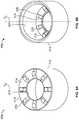
- FIGS. 9A and 9Bare perspective views of the vibration isolator 172 .
- the vibration isolator 172can include a cylindrical portion 212 and an annular portion 214 .
- the cylindrical portion 212can extend substantially circumferentially about a centerline axis C L .
- the annular portion 214can extend substantially radially with respect to the centerline axis C L between an inner rim 216 of the annular portion 214 and an outer rim 218 of the annular portion 214 .
- the inner rim 216can define a hole and the outer rim 218 can be connected to an end of the cylindrical portion 212 .
- the vibration isolator 172can be formed of an elastomer material suitable for dampening vibration.
- the cylindrical portion 212can be integrally formed with the annular portion 214 as a single structure. In other embodiments, one or more portions of the vibration isolator 172 can be separately formed.
- the vibration isolator 172can include first and second projections 220 and 222 .
- the annular portion 214can include the first projections 220 extending from a first side of the annular portion 214 and can include the second projections 222 extending from a second side of the annular portion 214 . Accordingly, the first and second projections 220 and 222 can be positioned on opposite sides, with the second projections 222 positioned substantially interior of the cylindrical portion 212 in a cavity defined by the vibration isolator 172 .
- the first projections 220can be shaped differently than the second projections 222 .
- the first projections 220can extend substantially radially outward with respect to the centerline axis C L along a surface of the annular portion 214 .
- the first projections 220can be shaped as ribs that extend radially from the inner rim 216 to the outer rim 218 .
- the first projections 220can be positioned in an array, substantially equally spaced circumferentially about the centerline axis C L .
- the second projections 222can be positioned opposite of the first projections 220 .
- the second projections 222can be positioned near an inner surface 224 of the cylindrical portion 212 but slightly spaced from the inner surface 224 by a gap 226 .
- the second projections 222can be positioned in an array, substantially equally spaced circumferentially about the centerline axis C L .
- the vibration isolator 172can be sized and configured to connect to a mounting structure of the flow control assembly 161 , such as the first and second posts 174 and 176 (shown in FIGS. 4 and 6 ).
- a mounting structure of the flow control assembly 161such as the first and second posts 174 and 176 (shown in FIGS. 4 and 6 ).
- one of the vibrations isolators 172can be positioned on the first post 174 with the cylindrical portion 212 wrapped around a circumferential portion of the first post 174 .
- the vibration isolator 172can be positioned on an end of the first post 174 between the end of the first post 174 and a supporting structure of the housing 150 , such as the first top supporting structure 180 of the housing top 152 .
- the second projections 222can extend substantially downward to abut the end of the first post 174 and the first projections 220 can extend substantially upward to abut the first top stop 186 of the first top supporting structure 180 . This can allow the first and second projections 220 and 222 to dampen vibration of the flow control assembly 161 in an axial direction with respect to the centerline axis C L .
- the inner rim 216 of the annular portion 214can abut the first top projection 184 of the first top supporting structure 180 .
- the first top projection 184can extend into a hole defined by the first post 174 , with the vibration isolator 172 holding the first top projection 184 substantially centrally in that hole to reduce or prevent contact between the first post 174 and the first top projection 184 . This can allow the annular portion 214 of the vibration isolator 172 to dampen vibration of the flow control assembly 161 in directions radial to the centerline axis C L .
- the vibration isolators 172can also be positioned on a bottom end of the first post 174 and/or either or both ends of the second post 176 .
- the vibration isolator 172can be positioned on a bottom end of the first post 174 , with the circumferential portion 212 wrapped around a circumferential portion of the first post 174 , the second projections 222 abutting the bottom end of the first post 174 , and the first projections 220 abutting the printed circuit board 160 (shown in FIGS. 4-5 ).
- the inner rim 216 of the annular portion 214can abut the first bottom projection 200 of the first bottom support structure 196 which can hold the first bottom projection 200 substantially centrally in a hole defined by the first post 174 to reduce or prevent contact between the first post 174 and the first bottom projection 200 .
- Thiscan allow the annular portion 214 of the vibration isolator 172 to dampen vibration of the flow control assembly 161 in directions radial to the centerline axis C L .
- the flow control assembly 161can be mounted in the housing 150 while reducing noise caused by vibration of the flow control assembly 161 .
- the configuration of the vibration isolators 172can allow for relatively easy assembly, as the vibration isolators 172 can be slipped over the ends of the first and second top supporting structures 180 and 182 and the first and second bottom supporting structures 196 and 198 and hold the flow control assembly 161 in place without requiring additional fasteners other than the those already being used to secure the housing top 152 to the housing bottom 154 .
Landscapes
- Engineering & Computer Science (AREA)
- General Engineering & Computer Science (AREA)
- Mechanical Engineering (AREA)
- Physics & Mathematics (AREA)
- Chemical & Material Sciences (AREA)
- Combustion & Propulsion (AREA)
- Acoustics & Sound (AREA)
- Aviation & Aerospace Engineering (AREA)
- Vibration Prevention Devices (AREA)
- General Physics & Mathematics (AREA)
- Automation & Control Theory (AREA)
Abstract
Description
Claims (19)
Priority Applications (2)
| Application Number | Priority Date | Filing Date | Title |
|---|---|---|---|
| US15/337,484US10888173B2 (en) | 2016-10-28 | 2016-10-28 | Air controller with vibration isolators |
| US17/145,645US20210251392A1 (en) | 2016-10-28 | 2021-01-11 | Air Controller With Vibration Isolators |
Applications Claiming Priority (1)
| Application Number | Priority Date | Filing Date | Title |
|---|---|---|---|
| US15/337,484US10888173B2 (en) | 2016-10-28 | 2016-10-28 | Air controller with vibration isolators |
Related Child Applications (1)
| Application Number | Title | Priority Date | Filing Date |
|---|---|---|---|
| US17/145,645ContinuationUS20210251392A1 (en) | 2016-10-28 | 2021-01-11 | Air Controller With Vibration Isolators |
Publications (2)
| Publication Number | Publication Date |
|---|---|
| US20180116419A1 US20180116419A1 (en) | 2018-05-03 |
| US10888173B2true US10888173B2 (en) | 2021-01-12 |
Family
ID=62020670
Family Applications (2)
| Application Number | Title | Priority Date | Filing Date |
|---|---|---|---|
| US15/337,484Active2039-08-13US10888173B2 (en) | 2016-10-28 | 2016-10-28 | Air controller with vibration isolators |
| US17/145,645PendingUS20210251392A1 (en) | 2016-10-28 | 2021-01-11 | Air Controller With Vibration Isolators |
Family Applications After (1)
| Application Number | Title | Priority Date | Filing Date |
|---|---|---|---|
| US17/145,645PendingUS20210251392A1 (en) | 2016-10-28 | 2021-01-11 | Air Controller With Vibration Isolators |
Country Status (1)
| Country | Link |
|---|---|
| US (2) | US10888173B2 (en) |
Cited By (18)
| Publication number | Priority date | Publication date | Assignee | Title |
|---|---|---|---|---|
| US20210251392A1 (en)* | 2016-10-28 | 2021-08-19 | Sleep Number Corporation | Air Controller With Vibration Isolators |
| USD982360S1 (en) | 2016-11-09 | 2023-04-04 | Sleep Number Corporation | Mattress |
| US20230272788A1 (en)* | 2020-08-26 | 2023-08-31 | Jiangsu Youmay Electric Appliance Co., Ltd. | Electric Air Pump |
| US11786044B2 (en) | 2016-11-09 | 2023-10-17 | Sleep Number Corporation | Adjustable foundation with service position |
| US20230389196A1 (en)* | 2021-07-20 | 2023-11-30 | Denso Electronics Corporation | Electric device |
| US11832728B2 (en) | 2021-08-24 | 2023-12-05 | Sleep Number Corporation | Controlling vibration transmission within inflation assemblies |
| US11857076B2 (en) | 2013-03-11 | 2024-01-02 | Sleep Number Corporation | Adjustable bed system with foundations having first and second configurations |
| US11937705B2 (en) | 2016-10-28 | 2024-03-26 | Sleep Number Corporation | Air bed system with an air manifold |
| US11992129B2 (en) | 2016-11-09 | 2024-05-28 | Sleep Number Corporation | Bed with magnetic couplers |
| US12004651B2 (en) | 2020-12-18 | 2024-06-11 | Sleep Number Corporation | Bed foundation adjustment controls |
| USD1032243S1 (en) | 2022-01-03 | 2024-06-25 | Sleep Number Corporation | Mattress |
| US12053093B2 (en) | 2019-11-15 | 2024-08-06 | Sleep Number Corporation | Zipper mattress attachment |
| US12089746B2 (en) | 2017-08-23 | 2024-09-17 | Sleep Number Corporation | Fluid system for a bed |
| US12117028B2 (en) | 2015-12-31 | 2024-10-15 | Sleep Number Corporation | Foundation and frame for bed |
| US12171339B2 (en) | 2014-04-15 | 2024-12-24 | Sleep Number Corporation | Sleep system with modular foundation |
| US12392332B2 (en) | 2016-10-28 | 2025-08-19 | Sleep Number Corporation | Pump housing with vertically supported vibration isolators |
| US12414638B2 (en) | 2021-07-19 | 2025-09-16 | Sleep Number Corporation | Mattress with stacked air chambers |
| US12419436B2 (en) | 2021-07-19 | 2025-09-23 | Sleep Number Corporation | Multi-air chamber mattress with localized support |
Families Citing this family (27)
| Publication number | Priority date | Publication date | Assignee | Title |
|---|---|---|---|---|
| US8332975B2 (en) | 2009-08-31 | 2012-12-18 | Gentherm Incorporated | Climate-controlled topper member for medical beds |
| US10674832B2 (en) | 2013-12-30 | 2020-06-09 | Sleep Number Corporation | Inflatable air mattress with integrated control |
| US10342358B1 (en) | 2014-10-16 | 2019-07-09 | Sleep Number Corporation | Bed with integrated components and features |
| EP3242576A4 (en) | 2015-01-05 | 2018-07-25 | Select Comfort Corporation | Bed with user occupancy tracking |
| US10149549B2 (en) | 2015-08-06 | 2018-12-11 | Sleep Number Corporation | Diagnostics of bed and bedroom environment |
| US11571346B2 (en) | 2017-12-28 | 2023-02-07 | Sleep Number Corporation | Bed having rollover identifying feature |
| CN111770707B (en) | 2017-12-28 | 2023-02-24 | 数眠公司 | Bed with sleep stage detection feature |
| US10957335B2 (en) | 2017-12-28 | 2021-03-23 | Sleep Number Corporation | Home automation having user privacy protections |
| US11737938B2 (en) | 2017-12-28 | 2023-08-29 | Sleep Number Corporation | Snore sensing bed |
| CN111770706B (en) | 2017-12-28 | 2023-06-02 | 数眠公司 | A bed with a snore detection feature |
| CN112118773A (en) | 2018-01-05 | 2020-12-22 | 数眠公司 | Bed with Physiological Event Detection Features |
| CN112839566A (en) | 2018-03-07 | 2021-05-25 | 数眠公司 | Home-Based Stress Test |
| US11001447B2 (en) | 2018-09-05 | 2021-05-11 | Sleep Number Corporation | Lifting furniture |
| AU2019379575A1 (en) | 2018-11-14 | 2020-11-26 | Sleep Number Corporation | Using force sensors to determine sleep parameters |
| US11690461B2 (en) | 2018-12-31 | 2023-07-04 | Sleep Number Corporation | Home automation with features to improve sleep |
| USD968436S1 (en) | 2019-01-08 | 2022-11-01 | Sleep Number Corporation | Display screen or portion thereof with graphical user interface |
| EP3927216A4 (en) | 2019-02-22 | 2022-11-16 | Bryte, Inc. | Sleep platform pneumatics management system |
| CN112367906B (en) | 2019-04-08 | 2024-12-20 | 数眠公司 | Systems for sensing and controlling the bed environment |
| JP7530837B2 (en) | 2019-04-16 | 2024-08-08 | スリープ ナンバー コーポレイション | A pillow with wireless charging capabilities |
| WO2020219117A1 (en) | 2019-04-25 | 2020-10-29 | Sleep Number Corporation | Bed having features for improving a sleeper's body thermoregulation during sleep |
| USD916745S1 (en) | 2019-05-08 | 2021-04-20 | Sleep Number Corporation | Display screen or portion thereof with graphical user interface |
| CA3103491A1 (en) | 2019-06-03 | 2020-12-10 | Sleep Number Corporation | Mattress covering |
| USD1083443S1 (en) | 2019-12-31 | 2025-07-15 | Sleep Number Corporation | Mattress |
| CN114929072A (en) | 2020-01-03 | 2022-08-19 | 数眠公司 | Bed gas flow and temperature control |
| US20210227991A1 (en)* | 2020-01-24 | 2021-07-29 | Patientech Llc | Controllable beds |
| WO2021178353A1 (en) | 2020-03-02 | 2021-09-10 | Sleep Number Corporation | Bed having user context sensing features |
| JP7691999B2 (en) | 2020-04-01 | 2025-06-12 | スリープ ナンバー コーポレイション | Systems and methods for remote patient screening and triage - Patents.com |
Citations (134)
| Publication number | Priority date | Publication date | Assignee | Title |
|---|---|---|---|---|
| US1138457A (en)* | 1915-01-13 | 1915-05-04 | Karl Otto Dahlmeyer | Jar-molding machine. |
| US1377556A (en)* | 1921-05-10 | Vibbation-absobbing offiounting | ||
| US1502866A (en)* | 1923-05-11 | 1924-07-29 | Moore Arthur | Lamp support |
| US1766597A (en)* | 1923-05-31 | 1930-06-24 | Gen Railway Signal Co | Instrument casing for train-control systems |
| US1805785A (en)* | 1924-08-25 | 1931-05-19 | Kelvinator Corp | Refrigerated food cabinet |
| US2041353A (en)* | 1934-03-07 | 1936-05-19 | Gen Household Utillities Compa | Shockless mounting |
| US2173342A (en)* | 1938-11-16 | 1939-09-19 | Rosenzweig Siegfried | Vibration isolation unit |
| US2339549A (en)* | 1941-03-06 | 1944-01-18 | Firestone Tire & Rubber Co | Resilient washer |
| US2397804A (en)* | 1944-02-12 | 1946-04-02 | Soundscriber Corp | Vibration and shock mounting for fragile instruments |
| US2481505A (en)* | 1945-11-23 | 1949-09-13 | Us Sec War | Shock absorbing means |
| US2809005A (en)* | 1954-10-06 | 1957-10-08 | Kenneth E Goode | Shock and vibration mount having non-rotational features |
| US2852223A (en)* | 1955-09-29 | 1958-09-16 | Paul V Roberts | Anti-vibration mount |
| US3323764A (en)* | 1965-03-03 | 1967-06-06 | Wright Barry Corp | Shock and vibration mount |
| US3635332A (en)* | 1969-12-08 | 1972-01-18 | Donald R Ross | Shock-absorbing device |
| US3727865A (en) | 1970-10-09 | 1973-04-17 | Rca Corp | Suspension system |
| US3784994A (en)* | 1972-11-27 | 1974-01-15 | E Kery | Air bed |
| US3825374A (en)* | 1972-03-09 | 1974-07-23 | R Kondo | Air supply device |
| US4040590A (en)* | 1975-12-15 | 1977-08-09 | Korfund Dynamics Corporation | Vibration isolator with integral non-amplifying seismic restraint |
| US4238104A (en)* | 1978-08-14 | 1980-12-09 | Rex Hamilton | Energy absorbing motor mount assembly |
| US4476969A (en)* | 1982-04-12 | 1984-10-16 | Dykema Owen W | Dynamic recoil damping mechanism |
| US4522378A (en)* | 1983-11-02 | 1985-06-11 | Illinois Tool Works, Inc. | Wiper motor mounting grommet |
| US4766628A (en) | 1986-01-21 | 1988-08-30 | Walker Robert A | Air mattress with filler check valve and cap therefor |
| US4788729A (en) | 1985-04-14 | 1988-12-06 | Walker Robert A | Air mattress with audible pressure relief valve |
| USD300194S (en) | 1984-10-12 | 1989-03-14 | Walker Robert A | Air mattress |
| US4829616A (en) | 1985-10-25 | 1989-05-16 | Walker Robert A | Air control system for air bed |
| US4898360A (en)* | 1987-12-17 | 1990-02-06 | Alfred Teves Gmbh | Valve block assembly |
| US4897890A (en) | 1983-01-05 | 1990-02-06 | Walker Robert A | Air control system for air bed |
| US4908895A (en) | 1989-03-20 | 1990-03-20 | Walker Robert A | Air mattress |
| US4982466A (en)* | 1988-10-12 | 1991-01-08 | Leggett & Platt, Incorporated | Body support system |
| USD313973S (en) | 1988-12-30 | 1991-01-22 | Walker Robert A | Hand-held control unit for the operation of an inflatable air mattress |
| US4988069A (en)* | 1989-11-27 | 1991-01-29 | Baxter International Inc. | Stepping motor mounting |
| US4989823A (en)* | 1989-04-28 | 1991-02-05 | Leonard Studio Equipment, Inc. | Shock and vibration isolator |
| US4991244A (en) | 1990-01-05 | 1991-02-12 | Walker Robert A | Border for air bed |
| US5011379A (en)* | 1988-12-15 | 1991-04-30 | Nitto Kohki Co., Ltd. | Electromagnetic diaphragm pump |
| US5016409A (en)* | 1987-04-28 | 1991-05-21 | Shimizu Construction Co., Ltd. | Method for restraining response of a structure to outside disturbances and apparatus therefor |
| US5052904A (en)* | 1989-05-26 | 1991-10-01 | Itakura Soki | Aquarium air pump |
| US5072917A (en)* | 1987-05-21 | 1991-12-17 | Pleva Walter F | Uniform loading springs of improved configuration |
| US5123625A (en)* | 1989-11-24 | 1992-06-23 | Paulstra G.M.B.H. | Resilient support element with graded stiffnesses |
| US5144706A (en) | 1990-12-03 | 1992-09-08 | Walker Robert A | Bed foundation |
| US5170522A (en) | 1991-12-16 | 1992-12-15 | Select Comfort Corporation | Air adjustable bed |
| USD368475S (en) | 1994-11-01 | 1996-04-02 | Select Comfort Corporation | Hand held remote control unit |
| US5509154A (en)* | 1994-11-01 | 1996-04-23 | Select Comfort Corporation | Air control system for an air bed |
| US5564140A (en) | 1994-07-22 | 1996-10-15 | Select Comfort Corporation | Frame assembly for supporting a mattress |
| US5642546A (en) | 1995-09-19 | 1997-07-01 | Select Comfort Corporation | Inflatable mattress with improved border support wall |
| US5691037A (en)* | 1995-01-13 | 1997-11-25 | Minnesota Mining And Manufacturing Company | Damped laminates with improved fastener force retention, a method of making, and novel tools useful in making |
| US5761031A (en)* | 1996-11-15 | 1998-06-02 | International Business Machines Corporation | Conductive shock mount for reducing electromagnetic interference in a disk drive system |
| USD396403S (en)* | 1996-09-10 | 1998-07-28 | James Todd Whittaker | CD player mount |
| US5904172A (en)* | 1997-07-28 | 1999-05-18 | Select Comfort Corporation | Valve enclosure assembly |
| US6108844A (en) | 1998-03-11 | 2000-08-29 | Sleeptec, Inc. | Air mattress for a sleeper sofa |
| US6132183A (en)* | 1998-11-23 | 2000-10-17 | Carrier Corporation | Compressor mounting |
| US6202239B1 (en) | 1998-02-25 | 2001-03-20 | Select Comfort Corp. | Multi-zone support |
| US6247686B1 (en)* | 1998-05-20 | 2001-06-19 | Gate S.P.A. | Vibration damper block |
| US6302145B1 (en)* | 1997-08-25 | 2001-10-16 | Hill-Rom Services, Inc. | Valve assembly |
| US6371434B1 (en)* | 1996-09-09 | 2002-04-16 | Robert Bosch Gmbh | Spring arrangement apparatus for mounting a vibration-sensitive or shock-sensitive device |
| US6390445B2 (en)* | 2000-03-17 | 2002-05-21 | Smc Kabushiki Kaisha | Solenoid-operated valve |
| US6397419B1 (en) | 1999-03-10 | 2002-06-04 | Select Comfort Corporation | System and method for sleep surface adjustment |
| US6686711B2 (en) | 2000-11-15 | 2004-02-03 | Comfortaire Corporation | Air mattress control system and method |
| US6708357B2 (en) | 2002-01-14 | 2004-03-23 | Select Comfort Corporation | Corner piece for a soft-sided mattress |
| US20040130082A1 (en)* | 2003-01-02 | 2004-07-08 | Wen-Yuan Tsai | Mechanical isolator |
| US6763541B2 (en) | 2001-06-07 | 2004-07-20 | Select Comfort Corporation | Interactive air bed |
| US6804848B1 (en) | 2003-03-14 | 2004-10-19 | Comfortaire Corporation | High-profile mattress having an upper low-profile module with an air posturizing sleep surface |
| US6832397B2 (en) | 2000-07-07 | 2004-12-21 | Select Comfort Corporation | Bed foundation |
| USD502929S1 (en) | 2004-03-02 | 2005-03-15 | Select Comfort Corporation | Remote control |
| US6883191B2 (en) | 2000-07-07 | 2005-04-26 | Select Comfort Corporation | Leg and bracket assembly for a bed foundation |
| US6917520B2 (en)* | 2002-04-17 | 2005-07-12 | Hon Hai Precision Ind. Co., Ltd. | Fixing device for data storage apparatus |
| US20050158193A1 (en)* | 1999-10-21 | 2005-07-21 | Roke Lindsey J. | Linear compressor |
| US20050206058A1 (en)* | 2002-12-17 | 2005-09-22 | Masterson Peter A | Elastomeric pin isolator |
| US20050214098A1 (en)* | 2004-03-24 | 2005-09-29 | Franke Gregory C | Storage media drive isolation apparatus and methods |
| US20050284868A1 (en)* | 2004-06-28 | 2005-12-29 | Hyun-Bae Ko | Insulator for vehicular radiator |
| US7322801B2 (en) | 2003-08-26 | 2008-01-29 | Thomas Industries Inc. | Compact linear air pump and valve package |
| US7331054B2 (en)* | 2004-03-19 | 2008-02-12 | Hong Fu Jin Precision Industry (Shenzhen) Co., Ltd. | Vibration damping means for optical recording/reproducing apparatus |
| US20080077020A1 (en) | 2006-09-22 | 2008-03-27 | Bam Labs, Inc. | Method and apparatus for monitoring vital signs remotely |
| US20080128966A1 (en)* | 2006-12-05 | 2008-06-05 | Inventec Corporation | Damping ring for vibration isolation |
| US7394009B2 (en)* | 2005-01-18 | 2008-07-01 | Probe Specialists, Inc. | Drum cymbal washer |
| US20080181795A1 (en)* | 2007-01-26 | 2008-07-31 | Rapid Air Llc (A Wisconsin Limited Liability Company) | Multiple configuration air mattress pump system |
| US7444704B2 (en)* | 2005-02-16 | 2008-11-04 | Kci Licensing, Inc. | System and method for maintaining air inflatable mattress configuration |
| US7614855B2 (en)* | 2005-03-31 | 2009-11-10 | Arimitsu Of North America, Inc. | Pump and motor assembly |
| US7865988B2 (en) | 2004-03-16 | 2011-01-11 | Select Comfort Corporation | Sleeping surface having two longitudinally connected bladders with a support member |
| US20110020149A1 (en)* | 2009-07-23 | 2011-01-27 | Dongguan Tiger Point, Metal & Plastic Products Co. ,Ltd. | Air pump for inflatable article |
| US20110061169A1 (en)* | 2009-09-17 | 2011-03-17 | Caremed Supply, Inc. | Air mattress |
| US7926780B2 (en)* | 2007-08-30 | 2011-04-19 | Hong Fu Jin Precision Industry (Shenzhen) Co., Ltd. | Vibration dampening structure for electronic device |
| US20110144455A1 (en) | 2007-08-31 | 2011-06-16 | Bam Labs, Inc. | Systems and methods for monitoring a subject at rest |
| US8201292B2 (en)* | 2006-11-16 | 2012-06-19 | Stryker Corporation | Patient support surface with turn-assist |
| US8282452B2 (en) | 2008-11-06 | 2012-10-09 | Trane International Inc. | Roof assembly for an air handler |
| US8336369B2 (en)* | 2007-05-24 | 2012-12-25 | Select Comfort Corporation | System and method for detecting a leak in an air bed |
| US8444558B2 (en) | 2009-01-07 | 2013-05-21 | Bam Labs, Inc. | Apparatus for monitoring vital signs having fluid bladder beneath padding |
| US8480052B2 (en)* | 2011-01-11 | 2013-07-09 | Drs Tactical Systems, Inc. | Vibration isolating device |
| US20130230410A1 (en)* | 2012-03-01 | 2013-09-05 | Chun-Chung Tsai | Air Pump Having An Auto-Stop Control Device |
| USD691118S1 (en) | 2013-03-14 | 2013-10-08 | Select Comfort Corporation | Remote control |
| USD697874S1 (en) | 2013-03-15 | 2014-01-21 | Select Comfort Corporation | Remote control |
| USD698338S1 (en) | 2013-03-14 | 2014-01-28 | Select Comfort Corporation | Remote control |
| US8641391B2 (en)* | 2009-12-29 | 2014-02-04 | Foshan Shunde Xinshengyuan Electrical Appliances Co., Ltd | Built-in electric air pump for use in inflatable products |
| US8672853B2 (en) | 2010-06-15 | 2014-03-18 | Bam Labs, Inc. | Pressure sensor for monitoring a subject and pressure sensor with inflatable bladder |
| USD701536S1 (en) | 2013-07-26 | 2014-03-25 | Select Comfort Corporation | Air pump |
| US8727753B2 (en)* | 2009-01-30 | 2014-05-20 | Nitto Kohki Co., Ltd. | Air pump |
| US20140182061A1 (en) | 2012-12-27 | 2014-07-03 | Select Comfort Corporation | Distribution pad for a temperature control system |
| US8769747B2 (en) | 2008-04-04 | 2014-07-08 | Select Comfort Corporation | System and method for improved pressure adjustment |
| US20140239145A1 (en)* | 2013-02-22 | 2014-08-28 | Kyocera Document Solutions Inc. | Retaining structure for information recording device and image forming apparatus including retaining structure |
| US20140257571A1 (en) | 2013-03-11 | 2014-09-11 | Select Comfort Corporation | Switching means for an adjustable foundation system |
| US20140250597A1 (en) | 2013-03-11 | 2014-09-11 | Select Comfort Corporation | Adjustable bed foundation system with built-in self-test |
| US20140259418A1 (en) | 2013-03-14 | 2014-09-18 | Rob Nunn | Inflatable air mattress with light and voice controls |
| US20140259434A1 (en) | 2013-03-14 | 2014-09-18 | Rob Nunn | Inflatable air mattress system with detection techniques |
| US20140259431A1 (en) | 2013-03-14 | 2014-09-18 | Select Comfort Corporation | System and method for adjusting settings of a bed with a remote control |
| US20140277611A1 (en) | 2013-03-14 | 2014-09-18 | Rob Nunn | Inflatable air mattress system architecture |
| US20140277822A1 (en) | 2013-03-14 | 2014-09-18 | Rob Nunn | Inflatable air mattress sleep environment adjustment and suggestions |
| US20140259417A1 (en) | 2013-03-14 | 2014-09-18 | Rob Nunn | Inflatable air mattress snoring detection and response |
| US20140277778A1 (en) | 2013-03-14 | 2014-09-18 | Rob Nunn | Inflatable air mattress autofill and off bed pressure adjustment |
| US20140259433A1 (en) | 2013-03-14 | 2014-09-18 | Rob Nunn | Inflatable air mattress alarm and monitoring system |
| US20140339977A1 (en)* | 2012-01-30 | 2014-11-20 | Fjuitsu Technology Solutions Intellectual Property GmbH | Foot for a computer casing, and computer casing having a foot of said type |
| US20150007393A1 (en) | 2013-07-02 | 2015-01-08 | Select Comfort Corporation | Controller for multi-zone fluid chamber mattress system |
| US20150025327A1 (en) | 2013-07-18 | 2015-01-22 | Bam Labs, Inc. | Device and Method of Monitoring a Position and Predicting an Exit of a Subject on or from a Substrate |
| US8966689B2 (en) | 2012-11-19 | 2015-03-03 | Select Comfort Corporation | Multi-zone fluid chamber and mattress system |
| US8973183B1 (en) | 2014-01-02 | 2015-03-10 | Select Comfort Corporation | Sheet for a split-top adjustable bed |
| US8984687B2 (en) | 2013-03-14 | 2015-03-24 | Select Comfort Corporation | Partner snore feature for adjustable bed foundation |
| US20150083456A1 (en)* | 2012-01-30 | 2015-03-26 | 3M Innovative Properties Company | Conductive, vibration dampening isolator |
| US20150182418A1 (en) | 2014-01-02 | 2015-07-02 | Select Comfort Corporation | Massage furniture item and method of operation |
| US20150182399A1 (en) | 2014-01-02 | 2015-07-02 | Select Comfort Corporation | Adjustable bed system with split head and split foot configuration |
| US20150182397A1 (en) | 2014-01-02 | 2015-07-02 | Select Comfort Corporation | Adjustable bed system having split-head and joined foot configuration |
| US20150182033A1 (en) | 2013-12-30 | 2015-07-02 | Select Comfort Corporation | Inflatable air mattress with integrated control |
| USD737250S1 (en) | 2013-03-14 | 2015-08-25 | Select Comfort Corporation | Remote control |
| US20150240906A1 (en)* | 2014-02-27 | 2015-08-27 | Aopen Inc. | Shock absorber |
| US9151285B2 (en)* | 2012-01-20 | 2015-10-06 | Air Kinetic Technologies Corp. | Air pump structure |
| US20150290059A1 (en) | 2014-04-15 | 2015-10-15 | Select Comfort Corporation | Adjustable bed system |
| US20160100696A1 (en) | 2014-10-10 | 2016-04-14 | Select Comfort Corporation | Bed having logic controller |
| US9360900B1 (en)* | 2013-08-21 | 2016-06-07 | Western Digital Technologies, Inc. | Captivating shock mounts for data storage devices using retention clips |
| US20160160880A1 (en)* | 2014-12-05 | 2016-06-09 | Nextern Inc. | Pneumatic distribution system using shared pump plenum |
| US9677557B2 (en)* | 2015-01-20 | 2017-06-13 | Hao Hsu | Sleeping system |
| US20170254582A1 (en)* | 2016-03-07 | 2017-09-07 | Whirlpool Patents Company | Refrigerator Vibration Isolating Compressor Mount |
| US20180001726A1 (en)* | 2015-03-18 | 2018-01-04 | Cikautxo, S.Coop. | Shock Absorber Assembly of a Suspension System of a Vehicle and Suspension System |
| US20180114548A1 (en)* | 2015-04-24 | 2018-04-26 | Nec Platforms, Ltd. | Hdd holding device, hdd unit, and information processing apparatus |
| US20180116420A1 (en)* | 2016-10-28 | 2018-05-03 | Select Comfort Corporation | Air Manifold |
| US20180116418A1 (en)* | 2016-10-28 | 2018-05-03 | Select Comfort Corporation | Noise Reducing Plunger |
| US20180119686A1 (en)* | 2016-10-28 | 2018-05-03 | Select Comfort Corporation | Pump With Vibration Isolators |
| US10441087B2 (en)* | 2015-02-24 | 2019-10-15 | Sleep Number Corporation | Mattress with adjustable firmness |
Family Cites Families (1)
| Publication number | Priority date | Publication date | Assignee | Title |
|---|---|---|---|---|
| US10888173B2 (en)* | 2016-10-28 | 2021-01-12 | Sleep Number Corporation | Air controller with vibration isolators |
- 2016
- 2016-10-28USUS15/337,484patent/US10888173B2/enactiveActive
- 2021
- 2021-01-11USUS17/145,645patent/US20210251392A1/enactivePending
Patent Citations (148)
| Publication number | Priority date | Publication date | Assignee | Title |
|---|---|---|---|---|
| US1377556A (en)* | 1921-05-10 | Vibbation-absobbing offiounting | ||
| US1138457A (en)* | 1915-01-13 | 1915-05-04 | Karl Otto Dahlmeyer | Jar-molding machine. |
| US1502866A (en)* | 1923-05-11 | 1924-07-29 | Moore Arthur | Lamp support |
| US1766597A (en)* | 1923-05-31 | 1930-06-24 | Gen Railway Signal Co | Instrument casing for train-control systems |
| US1805785A (en)* | 1924-08-25 | 1931-05-19 | Kelvinator Corp | Refrigerated food cabinet |
| US2041353A (en)* | 1934-03-07 | 1936-05-19 | Gen Household Utillities Compa | Shockless mounting |
| US2173342A (en)* | 1938-11-16 | 1939-09-19 | Rosenzweig Siegfried | Vibration isolation unit |
| US2339549A (en)* | 1941-03-06 | 1944-01-18 | Firestone Tire & Rubber Co | Resilient washer |
| US2397804A (en)* | 1944-02-12 | 1946-04-02 | Soundscriber Corp | Vibration and shock mounting for fragile instruments |
| US2481505A (en)* | 1945-11-23 | 1949-09-13 | Us Sec War | Shock absorbing means |
| US2809005A (en)* | 1954-10-06 | 1957-10-08 | Kenneth E Goode | Shock and vibration mount having non-rotational features |
| US2852223A (en)* | 1955-09-29 | 1958-09-16 | Paul V Roberts | Anti-vibration mount |
| US3323764A (en)* | 1965-03-03 | 1967-06-06 | Wright Barry Corp | Shock and vibration mount |
| US3635332A (en)* | 1969-12-08 | 1972-01-18 | Donald R Ross | Shock-absorbing device |
| US3727865A (en) | 1970-10-09 | 1973-04-17 | Rca Corp | Suspension system |
| US3825374A (en)* | 1972-03-09 | 1974-07-23 | R Kondo | Air supply device |
| US3784994A (en)* | 1972-11-27 | 1974-01-15 | E Kery | Air bed |
| US4040590A (en)* | 1975-12-15 | 1977-08-09 | Korfund Dynamics Corporation | Vibration isolator with integral non-amplifying seismic restraint |
| US4238104A (en)* | 1978-08-14 | 1980-12-09 | Rex Hamilton | Energy absorbing motor mount assembly |
| US4476969A (en)* | 1982-04-12 | 1984-10-16 | Dykema Owen W | Dynamic recoil damping mechanism |
| US4897890A (en) | 1983-01-05 | 1990-02-06 | Walker Robert A | Air control system for air bed |
| US4890344A (en) | 1983-01-05 | 1990-01-02 | Walker Robert A | Air control system for air bed |
| US4522378A (en)* | 1983-11-02 | 1985-06-11 | Illinois Tool Works, Inc. | Wiper motor mounting grommet |
| USD300194S (en) | 1984-10-12 | 1989-03-14 | Walker Robert A | Air mattress |
| US4788729A (en) | 1985-04-14 | 1988-12-06 | Walker Robert A | Air mattress with audible pressure relief valve |
| US4829616A (en) | 1985-10-25 | 1989-05-16 | Walker Robert A | Air control system for air bed |
| US4766628A (en) | 1986-01-21 | 1988-08-30 | Walker Robert A | Air mattress with filler check valve and cap therefor |
| US5016409A (en)* | 1987-04-28 | 1991-05-21 | Shimizu Construction Co., Ltd. | Method for restraining response of a structure to outside disturbances and apparatus therefor |
| US5072917A (en)* | 1987-05-21 | 1991-12-17 | Pleva Walter F | Uniform loading springs of improved configuration |
| US4898360A (en)* | 1987-12-17 | 1990-02-06 | Alfred Teves Gmbh | Valve block assembly |
| US4982466A (en)* | 1988-10-12 | 1991-01-08 | Leggett & Platt, Incorporated | Body support system |
| US5011379A (en)* | 1988-12-15 | 1991-04-30 | Nitto Kohki Co., Ltd. | Electromagnetic diaphragm pump |
| USD313973S (en) | 1988-12-30 | 1991-01-22 | Walker Robert A | Hand-held control unit for the operation of an inflatable air mattress |
| US4908895A (en) | 1989-03-20 | 1990-03-20 | Walker Robert A | Air mattress |
| US4989823A (en)* | 1989-04-28 | 1991-02-05 | Leonard Studio Equipment, Inc. | Shock and vibration isolator |
| US5052904A (en)* | 1989-05-26 | 1991-10-01 | Itakura Soki | Aquarium air pump |
| US5123625A (en)* | 1989-11-24 | 1992-06-23 | Paulstra G.M.B.H. | Resilient support element with graded stiffnesses |
| US4988069A (en)* | 1989-11-27 | 1991-01-29 | Baxter International Inc. | Stepping motor mounting |
| US4991244A (en) | 1990-01-05 | 1991-02-12 | Walker Robert A | Border for air bed |
| US5144706A (en) | 1990-12-03 | 1992-09-08 | Walker Robert A | Bed foundation |
| US5170522A (en) | 1991-12-16 | 1992-12-15 | Select Comfort Corporation | Air adjustable bed |
| US5564140A (en) | 1994-07-22 | 1996-10-15 | Select Comfort Corporation | Frame assembly for supporting a mattress |
| US6037723A (en) | 1994-11-01 | 2000-03-14 | Select Comfort Corporation | Air control system for an air bed |
| US6483264B1 (en) | 1994-11-01 | 2002-11-19 | Select Comfort Corporation | Air control system for an air bed |
| US5652484A (en) | 1994-11-01 | 1997-07-29 | Select Comfort Corporation | Air control system for an air bed |
| US5509154A (en)* | 1994-11-01 | 1996-04-23 | Select Comfort Corporation | Air control system for an air bed |
| USD368475S (en) | 1994-11-01 | 1996-04-02 | Select Comfort Corporation | Hand held remote control unit |
| US5903941A (en) | 1994-11-01 | 1999-05-18 | Select Comfort Corporation | Air control system for an air bed |
| US5691037A (en)* | 1995-01-13 | 1997-11-25 | Minnesota Mining And Manufacturing Company | Damped laminates with improved fastener force retention, a method of making, and novel tools useful in making |
| US5642546A (en) | 1995-09-19 | 1997-07-01 | Select Comfort Corporation | Inflatable mattress with improved border support wall |
| US5765246A (en) | 1995-09-19 | 1998-06-16 | Select Comfort Corporation | Inflatable mattress with improved border support wall |
| US6371434B1 (en)* | 1996-09-09 | 2002-04-16 | Robert Bosch Gmbh | Spring arrangement apparatus for mounting a vibration-sensitive or shock-sensitive device |
| USD396403S (en)* | 1996-09-10 | 1998-07-28 | James Todd Whittaker | CD player mount |
| US5761031A (en)* | 1996-11-15 | 1998-06-02 | International Business Machines Corporation | Conductive shock mount for reducing electromagnetic interference in a disk drive system |
| US5904172A (en)* | 1997-07-28 | 1999-05-18 | Select Comfort Corporation | Valve enclosure assembly |
| US6302145B1 (en)* | 1997-08-25 | 2001-10-16 | Hill-Rom Services, Inc. | Valve assembly |
| US6202239B1 (en) | 1998-02-25 | 2001-03-20 | Select Comfort Corp. | Multi-zone support |
| US6108844A (en) | 1998-03-11 | 2000-08-29 | Sleeptec, Inc. | Air mattress for a sleeper sofa |
| US6161231A (en) | 1998-03-11 | 2000-12-19 | Sleeptec, Inc. | Sleeper sofa with an air mattress |
| US6247686B1 (en)* | 1998-05-20 | 2001-06-19 | Gate S.P.A. | Vibration damper block |
| US6132183A (en)* | 1998-11-23 | 2000-10-17 | Carrier Corporation | Compressor mounting |
| US6397419B1 (en) | 1999-03-10 | 2002-06-04 | Select Comfort Corporation | System and method for sleep surface adjustment |
| US20050158193A1 (en)* | 1999-10-21 | 2005-07-21 | Roke Lindsey J. | Linear compressor |
| US6390445B2 (en)* | 2000-03-17 | 2002-05-21 | Smc Kabushiki Kaisha | Solenoid-operated valve |
| US6832397B2 (en) | 2000-07-07 | 2004-12-21 | Select Comfort Corporation | Bed foundation |
| US6883191B2 (en) | 2000-07-07 | 2005-04-26 | Select Comfort Corporation | Leg and bracket assembly for a bed foundation |
| US6686711B2 (en) | 2000-11-15 | 2004-02-03 | Comfortaire Corporation | Air mattress control system and method |
| US6763541B2 (en) | 2001-06-07 | 2004-07-20 | Select Comfort Corporation | Interactive air bed |
| US6708357B2 (en) | 2002-01-14 | 2004-03-23 | Select Comfort Corporation | Corner piece for a soft-sided mattress |
| US6917520B2 (en)* | 2002-04-17 | 2005-07-12 | Hon Hai Precision Ind. Co., Ltd. | Fixing device for data storage apparatus |
| US20050206058A1 (en)* | 2002-12-17 | 2005-09-22 | Masterson Peter A | Elastomeric pin isolator |
| US20040130082A1 (en)* | 2003-01-02 | 2004-07-08 | Wen-Yuan Tsai | Mechanical isolator |
| US6804848B1 (en) | 2003-03-14 | 2004-10-19 | Comfortaire Corporation | High-profile mattress having an upper low-profile module with an air posturizing sleep surface |
| US7389554B1 (en) | 2003-03-14 | 2008-06-24 | Comfortaire Corporation | Air sleep system with dual elevating air posturizing sleep surfaces |
| US7322801B2 (en) | 2003-08-26 | 2008-01-29 | Thomas Industries Inc. | Compact linear air pump and valve package |
| USD502929S1 (en) | 2004-03-02 | 2005-03-15 | Select Comfort Corporation | Remote control |
| US7865988B2 (en) | 2004-03-16 | 2011-01-11 | Select Comfort Corporation | Sleeping surface having two longitudinally connected bladders with a support member |
| US7331054B2 (en)* | 2004-03-19 | 2008-02-12 | Hong Fu Jin Precision Industry (Shenzhen) Co., Ltd. | Vibration damping means for optical recording/reproducing apparatus |
| US20050214098A1 (en)* | 2004-03-24 | 2005-09-29 | Franke Gregory C | Storage media drive isolation apparatus and methods |
| US20050284868A1 (en)* | 2004-06-28 | 2005-12-29 | Hyun-Bae Ko | Insulator for vehicular radiator |
| US7394009B2 (en)* | 2005-01-18 | 2008-07-01 | Probe Specialists, Inc. | Drum cymbal washer |
| US7444704B2 (en)* | 2005-02-16 | 2008-11-04 | Kci Licensing, Inc. | System and method for maintaining air inflatable mattress configuration |
| US7614855B2 (en)* | 2005-03-31 | 2009-11-10 | Arimitsu Of North America, Inc. | Pump and motor assembly |
| US20080077020A1 (en) | 2006-09-22 | 2008-03-27 | Bam Labs, Inc. | Method and apparatus for monitoring vital signs remotely |
| US8201292B2 (en)* | 2006-11-16 | 2012-06-19 | Stryker Corporation | Patient support surface with turn-assist |
| US20080128966A1 (en)* | 2006-12-05 | 2008-06-05 | Inventec Corporation | Damping ring for vibration isolation |
| US20080181795A1 (en)* | 2007-01-26 | 2008-07-31 | Rapid Air Llc (A Wisconsin Limited Liability Company) | Multiple configuration air mattress pump system |
| US8931329B2 (en) | 2007-05-24 | 2015-01-13 | Select Comfort Corporation | System and method for detecting a leak in an air bed |
| US8336369B2 (en)* | 2007-05-24 | 2012-12-25 | Select Comfort Corporation | System and method for detecting a leak in an air bed |
| US7926780B2 (en)* | 2007-08-30 | 2011-04-19 | Hong Fu Jin Precision Industry (Shenzhen) Co., Ltd. | Vibration dampening structure for electronic device |
| US20110144455A1 (en) | 2007-08-31 | 2011-06-16 | Bam Labs, Inc. | Systems and methods for monitoring a subject at rest |
| US20150374137A1 (en) | 2008-04-04 | 2015-12-31 | Select Comfort Corporation | System and method for improved pressure adjustment |
| US8769747B2 (en) | 2008-04-04 | 2014-07-08 | Select Comfort Corporation | System and method for improved pressure adjustment |
| US8282452B2 (en) | 2008-11-06 | 2012-10-09 | Trane International Inc. | Roof assembly for an air handler |
| US8444558B2 (en) | 2009-01-07 | 2013-05-21 | Bam Labs, Inc. | Apparatus for monitoring vital signs having fluid bladder beneath padding |
| US8727753B2 (en)* | 2009-01-30 | 2014-05-20 | Nitto Kohki Co., Ltd. | Air pump |
| US20110020149A1 (en)* | 2009-07-23 | 2011-01-27 | Dongguan Tiger Point, Metal & Plastic Products Co. ,Ltd. | Air pump for inflatable article |
| US20110061169A1 (en)* | 2009-09-17 | 2011-03-17 | Caremed Supply, Inc. | Air mattress |
| US8641391B2 (en)* | 2009-12-29 | 2014-02-04 | Foshan Shunde Xinshengyuan Electrical Appliances Co., Ltd | Built-in electric air pump for use in inflatable products |
| US8672853B2 (en) | 2010-06-15 | 2014-03-18 | Bam Labs, Inc. | Pressure sensor for monitoring a subject and pressure sensor with inflatable bladder |
| US8480052B2 (en)* | 2011-01-11 | 2013-07-09 | Drs Tactical Systems, Inc. | Vibration isolating device |
| US9151285B2 (en)* | 2012-01-20 | 2015-10-06 | Air Kinetic Technologies Corp. | Air pump structure |
| US20140339977A1 (en)* | 2012-01-30 | 2014-11-20 | Fjuitsu Technology Solutions Intellectual Property GmbH | Foot for a computer casing, and computer casing having a foot of said type |
| US20150083456A1 (en)* | 2012-01-30 | 2015-03-26 | 3M Innovative Properties Company | Conductive, vibration dampening isolator |
| US20130230410A1 (en)* | 2012-03-01 | 2013-09-05 | Chun-Chung Tsai | Air Pump Having An Auto-Stop Control Device |
| US8966689B2 (en) | 2012-11-19 | 2015-03-03 | Select Comfort Corporation | Multi-zone fluid chamber and mattress system |
| US20140182061A1 (en) | 2012-12-27 | 2014-07-03 | Select Comfort Corporation | Distribution pad for a temperature control system |
| US20150366366A1 (en) | 2012-12-27 | 2015-12-24 | Select Comfort Corporation | Distribution pad for a temperature control system |
| US20140239145A1 (en)* | 2013-02-22 | 2014-08-28 | Kyocera Document Solutions Inc. | Retaining structure for information recording device and image forming apparatus including retaining structure |
| US20140257571A1 (en) | 2013-03-11 | 2014-09-11 | Select Comfort Corporation | Switching means for an adjustable foundation system |
| US20140250597A1 (en) | 2013-03-11 | 2014-09-11 | Select Comfort Corporation | Adjustable bed foundation system with built-in self-test |
| US20140259417A1 (en) | 2013-03-14 | 2014-09-18 | Rob Nunn | Inflatable air mattress snoring detection and response |
| US20150026896A1 (en) | 2013-03-14 | 2015-01-29 | Select Comfort Corporation | System and Method for Adjusting Settings of a Bed With a Remote Control |
| US20140277611A1 (en) | 2013-03-14 | 2014-09-18 | Rob Nunn | Inflatable air mattress system architecture |
| US20140277778A1 (en) | 2013-03-14 | 2014-09-18 | Rob Nunn | Inflatable air mattress autofill and off bed pressure adjustment |
| US20140259433A1 (en) | 2013-03-14 | 2014-09-18 | Rob Nunn | Inflatable air mattress alarm and monitoring system |
| US20140259431A1 (en) | 2013-03-14 | 2014-09-18 | Select Comfort Corporation | System and method for adjusting settings of a bed with a remote control |
| US20140277822A1 (en) | 2013-03-14 | 2014-09-18 | Rob Nunn | Inflatable air mattress sleep environment adjustment and suggestions |
| US20140259434A1 (en) | 2013-03-14 | 2014-09-18 | Rob Nunn | Inflatable air mattress system with detection techniques |
| USD698338S1 (en) | 2013-03-14 | 2014-01-28 | Select Comfort Corporation | Remote control |
| USD737250S1 (en) | 2013-03-14 | 2015-08-25 | Select Comfort Corporation | Remote control |
| US20140259418A1 (en) | 2013-03-14 | 2014-09-18 | Rob Nunn | Inflatable air mattress with light and voice controls |
| USD691118S1 (en) | 2013-03-14 | 2013-10-08 | Select Comfort Corporation | Remote control |
| US8984687B2 (en) | 2013-03-14 | 2015-03-24 | Select Comfort Corporation | Partner snore feature for adjustable bed foundation |
| US20150157137A1 (en) | 2013-03-14 | 2015-06-11 | Select Comfort Corporation | Inflatable Air Mattress System Architecture |
| US20150157519A1 (en) | 2013-03-14 | 2015-06-11 | Select Comfort Corporation | Partner Snore Feature for Adjustable Bed Foundation |
| USD697874S1 (en) | 2013-03-15 | 2014-01-21 | Select Comfort Corporation | Remote control |
| US20150007393A1 (en) | 2013-07-02 | 2015-01-08 | Select Comfort Corporation | Controller for multi-zone fluid chamber mattress system |
| US20150025327A1 (en) | 2013-07-18 | 2015-01-22 | Bam Labs, Inc. | Device and Method of Monitoring a Position and Predicting an Exit of a Subject on or from a Substrate |
| USD701536S1 (en) | 2013-07-26 | 2014-03-25 | Select Comfort Corporation | Air pump |
| US9360900B1 (en)* | 2013-08-21 | 2016-06-07 | Western Digital Technologies, Inc. | Captivating shock mounts for data storage devices using retention clips |
| US20150182033A1 (en) | 2013-12-30 | 2015-07-02 | Select Comfort Corporation | Inflatable air mattress with integrated control |
| US20150182397A1 (en) | 2014-01-02 | 2015-07-02 | Select Comfort Corporation | Adjustable bed system having split-head and joined foot configuration |
| US20150182399A1 (en) | 2014-01-02 | 2015-07-02 | Select Comfort Corporation | Adjustable bed system with split head and split foot configuration |
| US20150182418A1 (en) | 2014-01-02 | 2015-07-02 | Select Comfort Corporation | Massage furniture item and method of operation |
| US8973183B1 (en) | 2014-01-02 | 2015-03-10 | Select Comfort Corporation | Sheet for a split-top adjustable bed |
| US20150240906A1 (en)* | 2014-02-27 | 2015-08-27 | Aopen Inc. | Shock absorber |
| US20150290059A1 (en) | 2014-04-15 | 2015-10-15 | Select Comfort Corporation | Adjustable bed system |
| US20160100696A1 (en) | 2014-10-10 | 2016-04-14 | Select Comfort Corporation | Bed having logic controller |
| US20160160880A1 (en)* | 2014-12-05 | 2016-06-09 | Nextern Inc. | Pneumatic distribution system using shared pump plenum |
| US9677557B2 (en)* | 2015-01-20 | 2017-06-13 | Hao Hsu | Sleeping system |
| US10441087B2 (en)* | 2015-02-24 | 2019-10-15 | Sleep Number Corporation | Mattress with adjustable firmness |
| US20180001726A1 (en)* | 2015-03-18 | 2018-01-04 | Cikautxo, S.Coop. | Shock Absorber Assembly of a Suspension System of a Vehicle and Suspension System |
| US20180114548A1 (en)* | 2015-04-24 | 2018-04-26 | Nec Platforms, Ltd. | Hdd holding device, hdd unit, and information processing apparatus |
| US20170254582A1 (en)* | 2016-03-07 | 2017-09-07 | Whirlpool Patents Company | Refrigerator Vibration Isolating Compressor Mount |
| US20180116420A1 (en)* | 2016-10-28 | 2018-05-03 | Select Comfort Corporation | Air Manifold |
| US20180116418A1 (en)* | 2016-10-28 | 2018-05-03 | Select Comfort Corporation | Noise Reducing Plunger |
| US20180119686A1 (en)* | 2016-10-28 | 2018-05-03 | Select Comfort Corporation | Pump With Vibration Isolators |
Non-Patent Citations (2)
| Title |
|---|
| U.S. Appl. No. 14/819,630, filed Aug. 6, 2015, Nunn et al. |
| U.S. Appl. No. 14/885,751, filed Oct. 16, 2015, Palashewski et al. |
Cited By (23)
| Publication number | Priority date | Publication date | Assignee | Title |
|---|---|---|---|---|
| US11857076B2 (en) | 2013-03-11 | 2024-01-02 | Sleep Number Corporation | Adjustable bed system with foundations having first and second configurations |
| US12310506B2 (en) | 2013-03-11 | 2025-05-27 | Sleep Number Corporation | Adjustable bed system with foundations having first and second configurations |
| US12171339B2 (en) | 2014-04-15 | 2024-12-24 | Sleep Number Corporation | Sleep system with modular foundation |
| US12117028B2 (en) | 2015-12-31 | 2024-10-15 | Sleep Number Corporation | Foundation and frame for bed |
| US20210251392A1 (en)* | 2016-10-28 | 2021-08-19 | Sleep Number Corporation | Air Controller With Vibration Isolators |
| US12392332B2 (en) | 2016-10-28 | 2025-08-19 | Sleep Number Corporation | Pump housing with vertically supported vibration isolators |
| US11937705B2 (en) | 2016-10-28 | 2024-03-26 | Sleep Number Corporation | Air bed system with an air manifold |
| US12290181B2 (en) | 2016-10-28 | 2025-05-06 | Sleep Number Corporation | Pump and manifold with unvalved vent |
| US12096856B2 (en) | 2016-11-09 | 2024-09-24 | Sleep Number Corporation | Adjustable foundation for a mattress |
| US11992129B2 (en) | 2016-11-09 | 2024-05-28 | Sleep Number Corporation | Bed with magnetic couplers |
| USD982360S1 (en) | 2016-11-09 | 2023-04-04 | Sleep Number Corporation | Mattress |
| US11786044B2 (en) | 2016-11-09 | 2023-10-17 | Sleep Number Corporation | Adjustable foundation with service position |
| US12279698B2 (en) | 2017-08-23 | 2025-04-22 | Sleep Number Corporation | Layer assembly for a bed to distribute air |
| US12089746B2 (en) | 2017-08-23 | 2024-09-17 | Sleep Number Corporation | Fluid system for a bed |
| US12053093B2 (en) | 2019-11-15 | 2024-08-06 | Sleep Number Corporation | Zipper mattress attachment |
| US12116989B2 (en)* | 2020-08-26 | 2024-10-15 | Jiangsu Youmay Electric Appliance Co., Ltd. | Electric air pump |
| US20230272788A1 (en)* | 2020-08-26 | 2023-08-31 | Jiangsu Youmay Electric Appliance Co., Ltd. | Electric Air Pump |
| US12004651B2 (en) | 2020-12-18 | 2024-06-11 | Sleep Number Corporation | Bed foundation adjustment controls |
| US12414638B2 (en) | 2021-07-19 | 2025-09-16 | Sleep Number Corporation | Mattress with stacked air chambers |
| US12419436B2 (en) | 2021-07-19 | 2025-09-23 | Sleep Number Corporation | Multi-air chamber mattress with localized support |
| US20230389196A1 (en)* | 2021-07-20 | 2023-11-30 | Denso Electronics Corporation | Electric device |
| US11832728B2 (en) | 2021-08-24 | 2023-12-05 | Sleep Number Corporation | Controlling vibration transmission within inflation assemblies |
| USD1032243S1 (en) | 2022-01-03 | 2024-06-25 | Sleep Number Corporation | Mattress |
Also Published As
| Publication number | Publication date |
|---|---|
| US20210251392A1 (en) | 2021-08-19 |
| US20180116419A1 (en) | 2018-05-03 |
Similar Documents
| Publication | Publication Date | Title |
|---|---|---|
| US20210251392A1 (en) | Air Controller With Vibration Isolators | |
| US20240011476A1 (en) | Pump With Vibration Isolators | |
| US11937705B2 (en) | Air bed system with an air manifold | |
| US11950702B2 (en) | Noise reducing plunger | |
| US8033797B2 (en) | Pump with automatic deactivation mechanism | |
| EP2298136B1 (en) | Air mattress | |
| SG143164A1 (en) | Inflatable bed having a built-in electric air pump unit for inflating a mattress assembly | |
| US7181795B2 (en) | Multi-chamber inflatable bed with unidirectional air inlet unit between chambers | |
| KR20030015245A (en) | Inflatable device with recessed fluid controller and modified adjustment device | |
| EP3653878A1 (en) | Pump-valve integrated mechanism | |
| JP2022504921A (en) | Pump valve combination device for airbag adjustment | |
| US10537185B2 (en) | Accelerated calibration system for a smart response technology mattress | |
| US6257842B1 (en) | Silencer and electromagnetic vibrating type pump employing the same | |
| US10808691B2 (en) | Air flow control device | |
| US20250268391A1 (en) | Tapered Exhaust Port for Valve Manifold | |
| AU2018101594A4 (en) | Air flow control device | |
| HK40001049B (en) | Air flow control device |
Legal Events
| Date | Code | Title | Description |
|---|---|---|---|
| AS | Assignment | Owner name:SELECT COMFORT CORPORATION, MINNESOTA Free format text:ASSIGNMENT OF ASSIGNORS INTEREST;ASSIGNOR:SHAKAL, ANTHONY JOHN;REEL/FRAME:040532/0090 Effective date:20161026 | |
| STPP | Information on status: patent application and granting procedure in general | Free format text:DOCKETED NEW CASE - READY FOR EXAMINATION | |
| AS | Assignment | Owner name:SLEEP NUMBER CORPORATION, MINNESOTA Free format text:CHANGE OF NAME;ASSIGNOR:SELECT COMFORT CORPORATION;REEL/FRAME:044456/0132 Effective date:20171101 | |
| AS | Assignment | Owner name:U.S. NATIONAL ASSOCIATION, AS ADMINISTRATIVE AGENT Free format text:SECURITY INTEREST;ASSIGNOR:SLEEP NUMBER CORPORATION;REEL/FRAME:048293/0536 Effective date:20190211 Owner name:U.S. NATIONAL ASSOCIATION, AS ADMINISTRATIVE AGENT, MINNESOTA Free format text:SECURITY INTEREST;ASSIGNOR:SLEEP NUMBER CORPORATION;REEL/FRAME:048293/0536 Effective date:20190211 | |
| STPP | Information on status: patent application and granting procedure in general | Free format text:NON FINAL ACTION MAILED | |
| STPP | Information on status: patent application and granting procedure in general | Free format text:RESPONSE TO NON-FINAL OFFICE ACTION ENTERED AND FORWARDED TO EXAMINER | |
| STPP | Information on status: patent application and granting procedure in general | Free format text:NOTICE OF ALLOWANCE MAILED -- APPLICATION RECEIVED IN OFFICE OF PUBLICATIONS | |
| STPP | Information on status: patent application and granting procedure in general | Free format text:PUBLICATIONS -- ISSUE FEE PAYMENT VERIFIED | |
| STCF | Information on status: patent grant | Free format text:PATENTED CASE | |
| CC | Certificate of correction |