US10884546B2 - Projection alignment - Google Patents
Projection alignmentDownload PDFInfo
- Publication number
- US10884546B2 US10884546B2US15/508,379US201415508379AUS10884546B2US 10884546 B2US10884546 B2US 10884546B2US 201415508379 AUS201415508379 AUS 201415508379AUS 10884546 B2US10884546 B2US 10884546B2
- Authority
- US
- United States
- Prior art keywords
- image
- projection
- initial
- interest
- content
- Prior art date
- Legal status (The legal status is an assumption and is not a legal conclusion. Google has not performed a legal analysis and makes no representation as to the accuracy of the status listed.)
- Expired - Fee Related
Links
Images


Classifications
- G—PHYSICS
- G06—COMPUTING OR CALCULATING; COUNTING
- G06F—ELECTRIC DIGITAL DATA PROCESSING
- G06F3/00—Input arrangements for transferring data to be processed into a form capable of being handled by the computer; Output arrangements for transferring data from processing unit to output unit, e.g. interface arrangements
- G06F3/01—Input arrangements or combined input and output arrangements for interaction between user and computer
- G06F3/03—Arrangements for converting the position or the displacement of a member into a coded form
- G06F3/041—Digitisers, e.g. for touch screens or touch pads, characterised by the transducing means
- G06F3/0416—Control or interface arrangements specially adapted for digitisers
- G06F3/0418—Control or interface arrangements specially adapted for digitisers for error correction or compensation, e.g. based on parallax, calibration or alignment
- H—ELECTRICITY
- H04—ELECTRIC COMMUNICATION TECHNIQUE
- H04N—PICTORIAL COMMUNICATION, e.g. TELEVISION
- H04N9/00—Details of colour television systems
- H04N9/12—Picture reproducers
- H04N9/31—Projection devices for colour picture display, e.g. using electronic spatial light modulators [ESLM]
- H04N9/3179—Video signal processing therefor
- H04N9/3185—Geometric adjustment, e.g. keystone or convergence
- G—PHYSICS
- G06—COMPUTING OR CALCULATING; COUNTING
- G06F—ELECTRIC DIGITAL DATA PROCESSING
- G06F3/00—Input arrangements for transferring data to be processed into a form capable of being handled by the computer; Output arrangements for transferring data from processing unit to output unit, e.g. interface arrangements
- G06F3/01—Input arrangements or combined input and output arrangements for interaction between user and computer
- G06F3/03—Arrangements for converting the position or the displacement of a member into a coded form
- G06F3/041—Digitisers, e.g. for touch screens or touch pads, characterised by the transducing means
- G06F3/042—Digitisers, e.g. for touch screens or touch pads, characterised by the transducing means by opto-electronic means
- G06F3/0425—Digitisers, e.g. for touch screens or touch pads, characterised by the transducing means by opto-electronic means using a single imaging device like a video camera for tracking the absolute position of a single or a plurality of objects with respect to an imaged reference surface, e.g. video camera imaging a display or a projection screen, a table or a wall surface, on which a computer generated image is displayed or projected
- G—PHYSICS
- G06—COMPUTING OR CALCULATING; COUNTING
- G06F—ELECTRIC DIGITAL DATA PROCESSING
- G06F3/00—Input arrangements for transferring data to be processed into a form capable of being handled by the computer; Output arrangements for transferring data from processing unit to output unit, e.g. interface arrangements
- G06F3/01—Input arrangements or combined input and output arrangements for interaction between user and computer
- G06F3/03—Arrangements for converting the position or the displacement of a member into a coded form
- G06F3/041—Digitisers, e.g. for touch screens or touch pads, characterised by the transducing means
- G06F3/042—Digitisers, e.g. for touch screens or touch pads, characterised by the transducing means by opto-electronic means
- G06F3/0428—Digitisers, e.g. for touch screens or touch pads, characterised by the transducing means by opto-electronic means by sensing at the edges of the touch surface the interruption of optical paths, e.g. an illumination plane, parallel to the touch surface which may be virtual
- H—ELECTRICITY
- H04—ELECTRIC COMMUNICATION TECHNIQUE
- H04N—PICTORIAL COMMUNICATION, e.g. TELEVISION
- H04N9/00—Details of colour television systems
- H04N9/12—Picture reproducers
- H04N9/31—Projection devices for colour picture display, e.g. using electronic spatial light modulators [ESLM]
- H04N9/3191—Testing thereof
- H04N9/3194—Testing thereof including sensor feedback
Definitions
- Projection systemsdisplay video signals that can represent still, partial motion, or full motion display images.
- the relative alignment of the projected image source and the projection surfaceaffect the amount of keystone distortion in the displayed image.
- Keystone distortioncan result when a projector projects an image along a projection axis that is non-orthogonal to the projection surface or display.
- the projectorcan be misaligned to the projection surface before or during projection causing single or multi-dimensional keystone distortion.
- FIG. 1is a diagram illustrating an example of a projection system in accordance with the present disclosure with a misaligned projection.
- FIG. 2is a diagram illustrating an example of the projection system of FIG. 1 with an aligned projection in accordance with the present disclosure.
- FIG. 3is a diagram illustrating an example of a projection system in accordance with the present disclosure.
- FIG. 4is a diagram illustrating an example of a projection display misalignment in accordance with the present disclosure.
- FIG. 5is a flow diagram illustrating an example method for adjusting a projected image in accordance with the present disclosure.
- FIG. 6is a flow diagram illustrating an example method for adjusting a projected image in accordance with the present disclosure.
- Misalignment of various components of an example projecting systemcan occur affecting the projection and viewing of images. Factory calibrated settings can be disturbed during shipment or set-up, for example.
- a touch sensitive projection display mat positionis changed relative to a projector.
- projectoris positioned at a location at an angle to the projection display mat or at a distance from the projection display mat such that the resulting images projected onto the mat do not fill the projection surface.
- misalignmentcan affect the resultant position of the projected image(s) onto the projection display mat.
- Correction of rotation, skew or asymmetric distortioncan be computationally intensive and thus employing a large amount of high central processing unit (CPU) resources, often slowing down other functions of the CPU.
- CPUcentral processing unit
- Examplesprovide real-time display alignment by adjusting a projector display through graphical processing unit (GPU) processes, allowing for a variety of adjustments to occur. Examples provide flexible and accurate projector alignment that can address four corner alignment with precise projector display control.
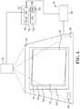
- an example projection system 100includes a computing device, or processing unit, 102 and a projector 104 .
- Projection system 100can include a projection display 106 .
- Computing device 102includes at least one GPU 108 and can include at least one CPU 140 (see, e.g., FIG. 3 ).
- Computing device 102is communicatively connected to projector 104 through a wireless or wired connection.
- Computing device 102can be a laptop computer, desktop computer, a tablet, a smart phone, or other device or processing system capable of electronic computing.
- computing device 102communicates with projector 104 to project an image or series of images onto projection display 106 .
- the image projected by projector 104can be any type of image, including but not limited to, information and/or images produced by instructions received by or stored in computing device 102 .
- Projector 104projects an image having a projected region of interest 110 within a total projection area 112 .
- projection area 112is a trapezoidal area that includes projector display region of interest 110 .
- Projector 104can be any type of video or image projector including rear or forward projecting projectors including a light source.
- Projection system 100can include one or more projectors 104 .
- Projector 104When multiple projectors 104 are used, they can be coordinated to project complete, whole images from multiple locations onto projection display 106 or project a series of partial images aligned together across projection display 106 to create a complete image.
- Projector 104is capable of producing at least two-dimensional images. In some examples, projector 104 is capable of producing three-dimensional images.
- Projection display 106can be any substantially planar or flat horizontal or vertical surface suitable for two-dimensional (2D) projection display.
- projection display 106can be a projection screen, a white board, or a touch sensitive mat, as described farther below.
- projection display 106is suitable for three-dimensional (3D) projection.
- projection display 106is a touch sensitive mat.
- Projection display, or touch sensitive mat, 106includes a front surface 114 suitable for displaying an image or series of images.
- Front surface 114includes a projector display area 116 and a border 118 .
- Front surface 114 of touch sensitive mat 106includes a touch sensitive surface of any suitable touch sensitive technology for detecting and tracking one or multiple touch inputs by a user in order to allow the user to interact with software being executed by computing device 102 or some other computing device (not shown) communicating with projector 104 and computing device 102 .
- touch sensitive surface 120extends over the entire front surface 114 .
- touch sensitive surface 120includes only a portion of front surface 114 .
- Touch sensitive surface 120can utilize known touch sensitive technologies such as optical, infrared, resistive, capacitive, strain gauge, acoustic wave, acoustic pulse recognition, or combination thereof.
- User interaction with touch sensitive mat 106can adjust or modify the display and information content through suitable touch to mat 106 with a user's hand, stylus, or other suitable instrument.
- Touch sensitive surface 120 and computing device 102are electrically coupled to one another such that user inputs received by surface 120 are communicated to computing device 102 .
- Touch sensitive surface 120 and computing device 102can be electrical connected with a suitable wireless or wired connection.
- a suitable wireless or wired connectionFor example, as with other electrical connections of projection system 100 , WI-FI, BLUETOOTH®, ultrasonic, electrical cables or other suitable electrical connection can be used.
- computing device 102directs projector 104 to project an image onto surface 114 of projection display 106 .
- the image projected by projector 104can include information and/or images produced by software executing within device 102 .
- a user(not shown) can interact with the image displayed on surface 114 by physically engaging the touch sensitive surface 120 of projection display 106 . Such interaction can take place through any suitable method such as, direct interaction with a user's hand, through a stylus, or other suitable user input device(s).
- an example projection display 106can include an extended control area 122 .
- a user(not shown) can interact with the image displayed on surface 114 by physically engaging extended control area 122 .
- Extended control area 122can be on the touch mat 106 or can be outside the touch mat 106 .
- Extended control area 122can be positioned outside display area 116 .
- Extended control area 122provides for touch sensitive interactions from a user, for example, via the user's hand or stylus (not shown) for further instruction and/or adjustment.
- an example projection system 100can include a sensing system 130 having a sensor 132 or cluster of sensors 132 to detect various parameters occurring on or near projection display 106 .
- a camera 134can be used with sensors 132 to detect various parameters, including alignment, on or near projection display 106 .
- Camera 134 and sensors 132are oriented to acquire images or data from touch sensitive mat 106 .
- camera 134is a high resolution color camera.
- Sensors 132can include light sensors, depth sensor, or three-dimensional user interface sensors, for example.
- at least one sensor 132is arranged to measure the intensity of ambient light of the environment surrounding the projection system 100 or the intensity of light reflected from various areas of the projection display 106 .
- border 118can be a first color and projection display area 116 can be a second color different than the first color. Detection of portions or all of the first color of border 118 and/or area 116 can indicate correct and aligned projection or misaligned projection of region of interest 110 onto projection display 106 .
- Camera 134can include sensors 132 or communicate with sensors to detect the intensity of light along the surface of projection display 106 .
- sensor 132is arranged to measure the intensity of light of the environment surrounding projection system 100 and color, or reflected light, of touch mat border 118 and projection display area 116 . Sensors 132 have geometric correlation to projection display 106 . Projection display 106 defines the area that sensors 132 within the sensor bundle are arranged to monitor and/or detect the conditions previously described. Each of the sensors 132 within bundle is electrically and communicatively coupled to computing device 102 such that data generated by sensors 132 can be transmitted to computing device 102 and commands issued by computing device 102 can be communicated to the sensors 132 during operation.
- any suitable electrical and/or communicative couplingcan be used to couple sensor bundle 132 to computing device 102 such as for example, an electric conductor, WI-FI, BLUETOOTH®, an optical connection, an ultrasonic connection, or some combination thereof.
- FIG. 1provides an example of the native, or initial, display output from projector 104 not aligned with, or coincident with, projector display area 114 of touch sensitive mat 106 .
- projection region of interest 110is rotated, for example, by 10 degrees, such that projection region of interest 110 is misaligned with respect to touch mat border 118 .
- projection region of interest 110can be inadvertently rotated or displaced due to changes made to the positioning one or both of projector 104 and mat 106 .
- the projection display region of interest 110does not fully utilize the surface area of the touch sensitive mat 106 , or can fall at least partially outside the area of the touch sensitive mat 106 .
- the portions of projection region of interest 110 that are no longer within the touch mat border 118are not properly viewable by a user.
- region of interest 110 and touch mat border 118are substantially rectangular and initially misaligned.
- FIG. 2illustrates an example of region of interest 110 of the projected image of FIG. 1 aligned with touch mat border 118 .
- Examples disclosed hereineffectively integrate the functionality of GPU 108 to align projector region of interest 110 within the defined area of touch mat border 118 .
- Alignmentcan correctly correlate images onto touch sensitive mat 106 .
- Alignment of original projected or region of interest 110 onto projection display 106can be through any three-dimensional rotational or realignment of the original image projection.
- GPU 108 processingcorrects misalignment of region of interest 110 .
- the corrected, or aligned, imageis projected from projector 104 .
- GPU 108can provide continuous monitoring and alignment, or can run periodically to meet a determined threshold or by a user.
- a threshold of misalignmentcan be set by a user or preset; upon exceeding the determined threshold, the projection is automatically realigned.
- Camera 134 and sensors 132detect display output content of the region of interest 110 onto projection display 106 and communicate with computing device 102 .
- FIG. 4illustrates an example of a projected region of interest 210 misaligned with a border 218 .
- Alignment of projected region of interest 210 within border 218can be verified by detecting corners of projection display 206 , and in some example corners of border 218 , and corners of region of interest 210 , and determining any correspondence between the sets of corners, based according to mapping methods, such as homography.
- mapping methodssuch as homography.
- vector offsetscan be generated between the two sets of corners in order to determine any correspondence.
- calibration operationscan be performed by GPU 108 , as will be further described.
- FIG. 4is reflective of another example misalignment.
- corners of touch mat border 218e.g., 318 a - d
- regions of initial projected region of interest 210e.g., 310 a - d
- region of interest 210and thus corner 310 a - d are positioned interior of corners 318 a - d of touch mat border 218 .
- Sensors 132can be used to detect corners 310 a - d and corners 318 a - d.
- camera 134can be used to take either a still image or a video of the whole mat 206 , or at least relevant portions of the mat 206 .
- a histogram of the image/videocan provide regions of interest, generally providing an indication of the difference in color intensity between the first color of touch mat border 218 and the second color of projection display area 216 reflecting at least a portion of region of interest 210 . Histogram equalization can be performed on the regions of interest to obtain high and low thresholds for an edge detection technique (e.g., Canny edge detection).
- edge detection techniquee.g., Canny edge detection
- edge points indicating the perimeter of the region of interest 218can be extracted (e.g., edge points for all four sides of the region 218 ).
- a line fitting techniquecan be used for determining four fitted lines, which can be representative of the perimeter of border 218 . Intersection of two lines from the four fitted lines can be used for calculating each corner 318 a - d .
- corners 318 a - d of the touch mat border 218can be determined even if one or more of the corners is occluded by an object in the still image (see, e.g., FIG. 1 ) due to difference in color intensities.
- corner detectioncan be performed to detecting corners 310 a - d of the projected region of interest 210 .
- sensors 132can differentiate a color intensity of projected region of interest 210 from a color intensity of an area outside the projected region of interest 210 .
- correspondence between the two sets of cornerscan be determined, based according to mapping methods, such as homography.
- projector 104can adjust settings for region of interest 210 reflected on to mat 206 to correspond to the detected border 218 of mat 206 .
- colors and/or corners of border 118 , 218 and region of interest 110 , 210are detected and applied into an alignment transformation (e.g., prospective warping transformation) performed by GPU 108 .
- the alignment transformationis applied to the projector display region of interest 110 , 210 .
- Alignment, or prospective warping, transformationis performed by GPU 108 to align the four corners of the touch mat border 118 , 218 to the four corners of the projected display region of interest 110 , 210 .
- a three by three dimensional matrix valuesare assigned to the corner positions and transformation of corner positions is performed and applied to coordinate alignment of corners 318 a - d and 310 a - d.
- the aligned region of interest 110 ais overlaid onto the projection display 106 using a GPU overlay buffer.
- Region of interest 110 ais applied by GPU 108 to projector 104 for projection onto display area 116 .
- the GPU overlay buffercan be varied to allow for extended control area 122 outside of the active area of touch mat 106 and can be used for extended control of the display.
- the GPU overlayaligns areas or corners of region of interest 110 to align or modify the image display to correspond with border 118 .
- the native/original display region of interest 110 formationis overlaid by the corrected display region of interest 110 a.
- computing device 102can include an Operating System (OS) 150 , a memory 152 , and a content display buffer 160 .
- Memory 152is suitable for storing data and parameters, operating system software, application software, and other instructions.
- Computing device 102can include other removable and/or non-removable storage where memory 152 , the non-removable storage, and the removable storage are implemented in computer readable storage media.
- Memory 152 and the other computer readable media in computing device 102can include volatile and/or non-volatile storage memory.
- OS 150can be any operating system suitable to coordinate software and hardware of computing device 102 such as Microsoft Windows®, Unix®) or Linux®, for example.
- CPU 140 controlled by OS 150executes instructions stored in memory 152 to provide image content to buffer 160 for temporary storage.
- GPU 108accesses the image content from the content display buffer 160 . Distortion, or misalignment, is corrected by GPU 108 so that aligned region of interest 110 a of protection 112 is consistent with display area 116 .
- Instructions stored in memory 152 for image alignment operationsare executed GPU 108 independent of OS 150 and CPU 140 for process and performance optimization of projection system 100 . In some examples, color correction can also be performed by GPU 108 .
- aligning the projector display region of interest 110 to border 118employs border 118 and projector display area detection from the calibrated sensors 132 and camera 134 .
- Content display buffer of OS 150stores content data of the image and GPU 108 creates a warped or aligned display content using the calculated alignment transformation image data stored in a corrected content display buffer of GPU 108 .
- Corrected, or aligned, image content displayis projected by projector 104 .
- the aligned image projectioncan be overlaid, or projected over, the original image projection.
- the original imagecan be projected transparently and the aligned image projected over the original image and within the projection area.
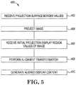
- FIG. 5is a flow diagram illustrating one example of a method 400 for adjusting projected image.
- Method 400can be performed via instructions stored in memory 152 that control projection system 100 .
- projection surface border values corresponding to a surface border location of a projection surfaceare received.
- an initial imageis projected onto the projection surface.
- initial projection display region values of the image projection corresponding to location of the image projection on the projection surfaceare received. 406 can occur before, after, or simultaneously with step 402 .
- an alignment transformationis performed based on the received projection surface border values and the initial projection display region values.
- an aligned display contentto adjust the image projection location values to coincide with the projection surface border location values is generated. As illustrated in FIG. 2 , aligned content is projected onto touch mat 106 by projector 104 .
- FIG. 6is a flow diagram illustrating one example of a method 500 for adjusting a projected image.
- Method 500can be performed via instructions stored in memory 152 that control projection system 100 .
- a border position of a projection surfaceis detected via a sensing system.
- image content of an image in a processing systemis determined.
- the image contentis communicated to a projector.
- the imageis projected toward the projection surface via the projector.
- the projected imagehas an initial projected region of interest within a projected display.
- the initial projected region of interestis detected via the sensing system.
- the detected border position and the projected region of interestis communicated from the sensing system to the processing system.
- the initial projected region of interestis transformed to coincide with the border position.
- aligned image display content of an aligned projected region of interest coinciding with the border positionis generated.
- the aligned image display contentis communicated to the projector.
- the aligned projected region of interestis projected within the border. The aligned projected region of interest is projected onto the mat over the initial projected region of interest.
Landscapes
- Engineering & Computer Science (AREA)
- General Engineering & Computer Science (AREA)
- Theoretical Computer Science (AREA)
- Physics & Mathematics (AREA)
- Human Computer Interaction (AREA)
- General Physics & Mathematics (AREA)
- Multimedia (AREA)
- Signal Processing (AREA)
- Geometry (AREA)
- Controls And Circuits For Display Device (AREA)
- Projection Apparatus (AREA)
Abstract
Description
Claims (12)
Applications Claiming Priority (1)
| Application Number | Priority Date | Filing Date | Title |
|---|---|---|---|
| PCT/US2014/054029WO2016036370A1 (en) | 2014-09-04 | 2014-09-04 | Projection alignment |
Publications (2)
| Publication Number | Publication Date |
|---|---|
| US20170308242A1 US20170308242A1 (en) | 2017-10-26 |
| US10884546B2true US10884546B2 (en) | 2021-01-05 |
Family
ID=55440228
Family Applications (1)
| Application Number | Title | Priority Date | Filing Date |
|---|---|---|---|
| US15/508,379Expired - Fee RelatedUS10884546B2 (en) | 2014-09-04 | 2014-09-04 | Projection alignment |
Country Status (3)
| Country | Link |
|---|---|
| US (1) | US10884546B2 (en) |
| TW (1) | TWI567473B (en) |
| WO (1) | WO2016036370A1 (en) |
Cited By (1)
| Publication number | Priority date | Publication date | Assignee | Title |
|---|---|---|---|---|
| US11838695B2 (en)* | 2021-02-01 | 2023-12-05 | Ali Corporation | Projection apparatus and keystone correction method |
Families Citing this family (4)
| Publication number | Priority date | Publication date | Assignee | Title |
|---|---|---|---|---|
| US20170351415A1 (en)* | 2016-06-06 | 2017-12-07 | Jonathan K. Cheng | System and interfaces for an interactive system |
| WO2019013758A1 (en)* | 2017-07-11 | 2019-01-17 | Hewlett-Packard Development Company, L.P. | Projection calibrations |
| JP2021071561A (en)* | 2019-10-30 | 2021-05-06 | パナソニックIpマネジメント株式会社 | Operation device, video projecting system, operation method, and program |
| US11303864B2 (en) | 2020-09-09 | 2022-04-12 | Christie Digital Systems Usa, Inc. | System and method for projector alignment using detected image features |
Citations (41)
| Publication number | Priority date | Publication date | Assignee | Title |
|---|---|---|---|---|
| US6367933B1 (en)* | 1998-10-02 | 2002-04-09 | Macronix International Co., Ltd. | Method and apparatus for preventing keystone distortion |
| US20020126136A1 (en)* | 2001-01-30 | 2002-09-12 | I-Jong Lin | Method for robust determination of visible points of a controllable display within a camera view |
| JP3409330B2 (en) | 1991-02-08 | 2003-05-26 | ソニー株式会社 | Adjustment device and adjustment method for projection display device |
| US6618076B1 (en)* | 1999-12-23 | 2003-09-09 | Justsystem Corporation | Method and apparatus for calibrating projector-camera system |
| US20050073661A1 (en)* | 2003-10-06 | 2005-04-07 | Nec Viewtechnology, Ltd. | Projector and method of projecting image from projector |
| US20050078092A1 (en) | 2003-10-08 | 2005-04-14 | Clapper Edward O. | Whiteboard desk projection display |
| TW200541329A (en) | 2004-03-29 | 2005-12-16 | Seiko Epson Corp | Image processing system, projector, program, information storage medium, and image processing method |
| US20060038962A1 (en) | 2004-08-19 | 2006-02-23 | Seiko Epson Corporation | Keystone correction using a part of edges of a screen |
| US20060109430A1 (en)* | 2004-11-19 | 2006-05-25 | Allen William J | Automatic zoom for screen fitting |
| US20060203207A1 (en) | 2005-03-09 | 2006-09-14 | Ikeda Roger M | Multi-dimensional keystone correction projection system and method |
| TW200701786A (en) | 2005-04-06 | 2007-01-01 | Seiko Epson Corp | Keystone correction for projector |
| US20070147705A1 (en) | 1999-12-15 | 2007-06-28 | Medispectra, Inc. | Methods and systems for correcting image misalignment |
| US7256772B2 (en) | 2003-04-08 | 2007-08-14 | Smart Technologies, Inc. | Auto-aligning touch system and method |
| US20080018591A1 (en) | 2006-07-20 | 2008-01-24 | Arkady Pittel | User Interfacing |
| TW200818114A (en) | 2006-08-11 | 2008-04-16 | Silicon Optix Inc | System and method for automated calibration and correction of display geometry and color |
| US7427983B1 (en)* | 2002-06-02 | 2008-09-23 | Steelcase Development Corporation | Visual communication system |
| US20090207411A1 (en) | 2008-02-18 | 2009-08-20 | Oakley William S | Aligning Multiple Image Frames in an LCoS Projector |
| US7599561B2 (en) | 2006-02-28 | 2009-10-06 | Microsoft Corporation | Compact interactive tabletop with projection-vision |
| US20090284538A1 (en)* | 2008-05-16 | 2009-11-19 | Asustek Computer Inc. | Video streaming data processing method |
| US20100054545A1 (en)* | 2005-06-02 | 2010-03-04 | Larry Elliott | Method and apparatus for displaying properties onto an object or life form |
| US7710391B2 (en) | 2002-05-28 | 2010-05-04 | Matthew Bell | Processing an image utilizing a spatially varying pattern |
| US20100238188A1 (en) | 2009-03-20 | 2010-09-23 | Sean Miceli | Efficient Display of Virtual Desktops on Multiple Independent Display Devices |
| US7864203B1 (en)* | 2005-09-13 | 2011-01-04 | Nvidia Corporation | System, method and computer program product for adjusting a display device viewing experience |
| US20110055729A1 (en)* | 2009-09-03 | 2011-03-03 | Steven Mason | User Interface for a Large Scale Multi-User, Multi-Touch System |
| US20110242054A1 (en) | 2010-04-01 | 2011-10-06 | Compal Communication, Inc. | Projection system with touch-sensitive projection image |
| JP2011250034A (en) | 2010-05-25 | 2011-12-08 | Seiko Epson Corp | Projector, projection state adjustment method, and projection state adjustment program |
| US20120001931A1 (en)* | 2010-07-02 | 2012-01-05 | Hon Hai Precision Industry Co., Ltd. | Adjusting system, method and projector including the same |
| US8121640B2 (en) | 2009-03-19 | 2012-02-21 | Microsoft Corporation | Dual module portable devices |
| US8199117B2 (en) | 2007-05-09 | 2012-06-12 | Microsoft Corporation | Archive for physical and digital objects |
| US20120162061A1 (en)* | 2010-06-25 | 2012-06-28 | Polyvision Corporation | Activation objects for interactive systems |
| US20120194562A1 (en)* | 2011-02-02 | 2012-08-02 | Victor Ivashin | Method For Spatial Smoothing In A Shader Pipeline For A Multi-Projector Display |
| US20120249463A1 (en)* | 2010-06-04 | 2012-10-04 | Smart Technologies Ulc | Interactive input system and method |
| US20130077236A1 (en) | 2011-09-27 | 2013-03-28 | Z124 | Magnetically securing two screens of a handheld communication device |
| US20130121601A1 (en)* | 2011-11-11 | 2013-05-16 | Haihua YU | Method and apparatus for determining projection area of image |
| US20130215138A1 (en)* | 2012-02-21 | 2013-08-22 | Canon Kabushiki Kaisha | Display system, display apparatus, and method for controlling display system |
| US20140085610A1 (en) | 2012-09-25 | 2014-03-27 | Microvision, Inc. | Virtual Segmentation of Interactive Scanning Laser Projector Display |
| US8736583B2 (en) | 2011-03-29 | 2014-05-27 | Intel Corporation | Virtual links between different displays to present a single virtual object |
| US20140146080A1 (en) | 2012-11-29 | 2014-05-29 | Seiko Epson Corporation | Method for Multiple Projector Display Using a GPU Frame Buffer |
| TW201421142A (en) | 2012-11-26 | 2014-06-01 | Everest Display Inc | Interactive projection system and method for calibrating position of light point thereof |
| US20140292647A1 (en)* | 2013-04-02 | 2014-10-02 | Fujitsu Limited | Interactive projector |
| WO2015116220A1 (en)* | 2014-01-31 | 2015-08-06 | Hewlett-Packard Development Company, L.P. | Touch sensitive mat of a system with a projector unit |
Family Cites Families (1)
| Publication number | Priority date | Publication date | Assignee | Title |
|---|---|---|---|---|
| TWI522624B (en)* | 2014-06-06 | 2016-02-21 | 旺矽科技股份有限公司 | Probe and method for manufacturaing a probe |
- 2014
- 2014-09-04USUS15/508,379patent/US10884546B2/ennot_activeExpired - Fee Related
- 2014-09-04WOPCT/US2014/054029patent/WO2016036370A1/enactiveApplication Filing
- 2015
- 2015-08-25TWTW104127718Apatent/TWI567473B/ennot_activeIP Right Cessation
Patent Citations (42)
| Publication number | Priority date | Publication date | Assignee | Title |
|---|---|---|---|---|
| JP3409330B2 (en) | 1991-02-08 | 2003-05-26 | ソニー株式会社 | Adjustment device and adjustment method for projection display device |
| US6367933B1 (en)* | 1998-10-02 | 2002-04-09 | Macronix International Co., Ltd. | Method and apparatus for preventing keystone distortion |
| US20070147705A1 (en) | 1999-12-15 | 2007-06-28 | Medispectra, Inc. | Methods and systems for correcting image misalignment |
| US6618076B1 (en)* | 1999-12-23 | 2003-09-09 | Justsystem Corporation | Method and apparatus for calibrating projector-camera system |
| US20020126136A1 (en)* | 2001-01-30 | 2002-09-12 | I-Jong Lin | Method for robust determination of visible points of a controllable display within a camera view |
| US7710391B2 (en) | 2002-05-28 | 2010-05-04 | Matthew Bell | Processing an image utilizing a spatially varying pattern |
| US7427983B1 (en)* | 2002-06-02 | 2008-09-23 | Steelcase Development Corporation | Visual communication system |
| US7256772B2 (en) | 2003-04-08 | 2007-08-14 | Smart Technologies, Inc. | Auto-aligning touch system and method |
| US20050073661A1 (en)* | 2003-10-06 | 2005-04-07 | Nec Viewtechnology, Ltd. | Projector and method of projecting image from projector |
| US20050078092A1 (en) | 2003-10-08 | 2005-04-14 | Clapper Edward O. | Whiteboard desk projection display |
| TW200541329A (en) | 2004-03-29 | 2005-12-16 | Seiko Epson Corp | Image processing system, projector, program, information storage medium, and image processing method |
| US20060038962A1 (en) | 2004-08-19 | 2006-02-23 | Seiko Epson Corporation | Keystone correction using a part of edges of a screen |
| US20060109430A1 (en)* | 2004-11-19 | 2006-05-25 | Allen William J | Automatic zoom for screen fitting |
| US20060203207A1 (en) | 2005-03-09 | 2006-09-14 | Ikeda Roger M | Multi-dimensional keystone correction projection system and method |
| TW200701786A (en) | 2005-04-06 | 2007-01-01 | Seiko Epson Corp | Keystone correction for projector |
| US20100054545A1 (en)* | 2005-06-02 | 2010-03-04 | Larry Elliott | Method and apparatus for displaying properties onto an object or life form |
| US7864203B1 (en)* | 2005-09-13 | 2011-01-04 | Nvidia Corporation | System, method and computer program product for adjusting a display device viewing experience |
| US7599561B2 (en) | 2006-02-28 | 2009-10-06 | Microsoft Corporation | Compact interactive tabletop with projection-vision |
| US20080018591A1 (en) | 2006-07-20 | 2008-01-24 | Arkady Pittel | User Interfacing |
| TW200818114A (en) | 2006-08-11 | 2008-04-16 | Silicon Optix Inc | System and method for automated calibration and correction of display geometry and color |
| US8199117B2 (en) | 2007-05-09 | 2012-06-12 | Microsoft Corporation | Archive for physical and digital objects |
| US20090207411A1 (en) | 2008-02-18 | 2009-08-20 | Oakley William S | Aligning Multiple Image Frames in an LCoS Projector |
| US20090284538A1 (en)* | 2008-05-16 | 2009-11-19 | Asustek Computer Inc. | Video streaming data processing method |
| US8121640B2 (en) | 2009-03-19 | 2012-02-21 | Microsoft Corporation | Dual module portable devices |
| US20100238188A1 (en) | 2009-03-20 | 2010-09-23 | Sean Miceli | Efficient Display of Virtual Desktops on Multiple Independent Display Devices |
| US20110055729A1 (en)* | 2009-09-03 | 2011-03-03 | Steven Mason | User Interface for a Large Scale Multi-User, Multi-Touch System |
| US20110242054A1 (en) | 2010-04-01 | 2011-10-06 | Compal Communication, Inc. | Projection system with touch-sensitive projection image |
| JP2011250034A (en) | 2010-05-25 | 2011-12-08 | Seiko Epson Corp | Projector, projection state adjustment method, and projection state adjustment program |
| US20120249463A1 (en)* | 2010-06-04 | 2012-10-04 | Smart Technologies Ulc | Interactive input system and method |
| US20120162061A1 (en)* | 2010-06-25 | 2012-06-28 | Polyvision Corporation | Activation objects for interactive systems |
| US20120001931A1 (en)* | 2010-07-02 | 2012-01-05 | Hon Hai Precision Industry Co., Ltd. | Adjusting system, method and projector including the same |
| US20120194562A1 (en)* | 2011-02-02 | 2012-08-02 | Victor Ivashin | Method For Spatial Smoothing In A Shader Pipeline For A Multi-Projector Display |
| US8736583B2 (en) | 2011-03-29 | 2014-05-27 | Intel Corporation | Virtual links between different displays to present a single virtual object |
| US20130077236A1 (en) | 2011-09-27 | 2013-03-28 | Z124 | Magnetically securing two screens of a handheld communication device |
| US20130121601A1 (en)* | 2011-11-11 | 2013-05-16 | Haihua YU | Method and apparatus for determining projection area of image |
| US20130215138A1 (en)* | 2012-02-21 | 2013-08-22 | Canon Kabushiki Kaisha | Display system, display apparatus, and method for controlling display system |
| US20140085610A1 (en) | 2012-09-25 | 2014-03-27 | Microvision, Inc. | Virtual Segmentation of Interactive Scanning Laser Projector Display |
| TW201421142A (en) | 2012-11-26 | 2014-06-01 | Everest Display Inc | Interactive projection system and method for calibrating position of light point thereof |
| US20140146080A1 (en) | 2012-11-29 | 2014-05-29 | Seiko Epson Corporation | Method for Multiple Projector Display Using a GPU Frame Buffer |
| US20140292647A1 (en)* | 2013-04-02 | 2014-10-02 | Fujitsu Limited | Interactive projector |
| WO2015116220A1 (en)* | 2014-01-31 | 2015-08-06 | Hewlett-Packard Development Company, L.P. | Touch sensitive mat of a system with a projector unit |
| US20160334938A1 (en)* | 2014-01-31 | 2016-11-17 | Hewlett-Packard Development Company, L.P. | Touch sensitive mat of a system with a projector unit |
Non-Patent Citations (2)
| Title |
|---|
| Matthew Flagg et al., "Improving the Speed of Virtual Rear Projection: A GPU-Centric Architecture," GVU Center and College of Computing, May 26, 2005, pp. 1-7, cc.gatech.edu. |
| Shahram Izadi et al., "C-Slate: A Multi-Touch and Object Recognition System for Remote Collaboration using Horizontal Surfaces," 2007, pp. 3-10, IEEE. |
Cited By (1)
| Publication number | Priority date | Publication date | Assignee | Title |
|---|---|---|---|---|
| US11838695B2 (en)* | 2021-02-01 | 2023-12-05 | Ali Corporation | Projection apparatus and keystone correction method |
Also Published As
| Publication number | Publication date |
|---|---|
| TWI567473B (en) | 2017-01-21 |
| WO2016036370A1 (en) | 2016-03-10 |
| TW201621454A (en) | 2016-06-16 |
| US20170308242A1 (en) | 2017-10-26 |
Similar Documents
| Publication | Publication Date | Title |
|---|---|---|
| US10241616B2 (en) | Calibration of sensors and projector | |
| TWI590189B (en) | Augmented reality method, system and computer-readable non-transitory storage medium | |
| JP5266954B2 (en) | Projection display apparatus and display method | |
| US10776898B2 (en) | Projection system, image processing device and projection method | |
| US10884546B2 (en) | Projection alignment | |
| US20170374331A1 (en) | Auto keystone correction and auto focus adjustment | |
| US9910507B2 (en) | Image display apparatus and pointing method for same | |
| KR20160030203A (en) | Systems and methods for producing a three-dimensional face model | |
| US10831238B2 (en) | Display method for flexible display screen and flexible display device | |
| US20160259402A1 (en) | Contact detection apparatus, projector apparatus, electronic board apparatus, digital signage apparatus, projector system, and contact detection method | |
| US20190073793A1 (en) | Electronic apparatus, method for controlling thereof and the computer readable recording medium | |
| CN107113417B (en) | Project an image onto an object | |
| TWI498792B (en) | Optical touch system and touch and display system | |
| US20160349918A1 (en) | Calibration for touch detection on projected display surfaces | |
| US20190155452A1 (en) | Presentation of a digital image of an object | |
| EP4113251A1 (en) | Calibration method of a system comprising an eye tracking device and a computing device comprising one or multiple screens | |
| JP2015142157A (en) | Image projection system, projection controller, projection controlling program | |
| CN113110732B (en) | Eye tracking control method and system for multi-screen display screen | |
| US10373324B2 (en) | Measurement apparatus that scans original, method of controlling the same, and storage medium | |
| TWI450576B (en) | Image processing device and image processing method | |
| KR20250082957A (en) | Image projection device and controlling method thereof |
Legal Events
| Date | Code | Title | Description |
|---|---|---|---|
| AS | Assignment | Owner name:HEWLETT-PACKARD DEVELOPMENT COMPANY, L.P., TEXAS Free format text:ASSIGNMENT OF ASSIGNORS INTEREST;ASSIGNORS:VINAS, SANTIAGO GARCIA-REYERO;KANG, JINMAN;SHORT, DAVID BRADLEY;SIGNING DATES FROM 20140829 TO 20140903;REEL/FRAME:042240/0629 | |
| STPP | Information on status: patent application and granting procedure in general | Free format text:NON FINAL ACTION MAILED | |
| STPP | Information on status: patent application and granting procedure in general | Free format text:RESPONSE TO NON-FINAL OFFICE ACTION ENTERED AND FORWARDED TO EXAMINER | |
| STPP | Information on status: patent application and granting procedure in general | Free format text:FINAL REJECTION MAILED | |
| STPP | Information on status: patent application and granting procedure in general | Free format text:DOCKETED NEW CASE - READY FOR EXAMINATION | |
| STPP | Information on status: patent application and granting procedure in general | Free format text:NON FINAL ACTION MAILED | |
| STPP | Information on status: patent application and granting procedure in general | Free format text:FINAL REJECTION MAILED | |
| STPP | Information on status: patent application and granting procedure in general | Free format text:RESPONSE AFTER FINAL ACTION FORWARDED TO EXAMINER | |
| STCF | Information on status: patent grant | Free format text:PATENTED CASE | |
| FEPP | Fee payment procedure | Free format text:MAINTENANCE FEE REMINDER MAILED (ORIGINAL EVENT CODE: REM.); ENTITY STATUS OF PATENT OWNER: LARGE ENTITY | |
| LAPS | Lapse for failure to pay maintenance fees | Free format text:PATENT EXPIRED FOR FAILURE TO PAY MAINTENANCE FEES (ORIGINAL EVENT CODE: EXP.); ENTITY STATUS OF PATENT OWNER: LARGE ENTITY | |
| STCH | Information on status: patent discontinuation | Free format text:PATENT EXPIRED DUE TO NONPAYMENT OF MAINTENANCE FEES UNDER 37 CFR 1.362 | |
| FP | Lapsed due to failure to pay maintenance fee | Effective date:20250105 |