US10882233B2 - Valve stem actuation - Google Patents
Valve stem actuationDownload PDFInfo
- Publication number
- US10882233B2 US10882233B2US15/773,824US201615773824AUS10882233B2US 10882233 B2US10882233 B2US 10882233B2US 201615773824 AUS201615773824 AUS 201615773824AUS 10882233 B2US10882233 B2US 10882233B2
- Authority
- US
- United States
- Prior art keywords
- piston
- valve stem
- actuation plate
- hot runner
- actuation
- Prior art date
- Legal status (The legal status is an assumption and is not a legal conclusion. Google has not performed a legal analysis and makes no representation as to the accuracy of the status listed.)
- Active, expires
Links
- 238000001746injection mouldingMethods0.000claimsdescription9
- 238000000034methodMethods0.000abstractdescription8
- 239000012778molding materialSubstances0.000description8
- 238000000465mouldingMethods0.000description8
- 230000008569processEffects0.000description6
- 238000002347injectionMethods0.000description5
- 239000007924injectionSubstances0.000description5
- 238000010926purgeMethods0.000description4
- 230000004888barrier functionEffects0.000description3
- 238000012423maintenanceMethods0.000description3
- 239000000463materialSubstances0.000description3
- 239000000155meltSubstances0.000description3
- 238000004519manufacturing processMethods0.000description2
- 230000036961partial effectEffects0.000description2
- 230000008439repair processEffects0.000description2
- 239000002356single layerSubstances0.000description2
- 239000000243solutionSubstances0.000description2
- 230000002159abnormal effectEffects0.000description1
- 239000000654additiveSubstances0.000description1
- 230000000996additive effectEffects0.000description1
- 235000013361beverageNutrition0.000description1
- 238000000071blow mouldingMethods0.000description1
- 238000005219brazingMethods0.000description1
- 238000004891communicationMethods0.000description1
- 230000001351cycling effectEffects0.000description1
- 230000003247decreasing effectEffects0.000description1
- 238000009792diffusion processMethods0.000description1
- 238000005553drillingMethods0.000description1
- 230000000694effectsEffects0.000description1
- 239000012530fluidSubstances0.000description1
- 238000010100freeform fabricationMethods0.000description1
- 239000012943hotmeltSubstances0.000description1
- 239000010410layerSubstances0.000description1
- 230000000670limiting effectEffects0.000description1
- 230000007246mechanismEffects0.000description1
- 238000012986modificationMethods0.000description1
- 230000004048modificationEffects0.000description1
- 238000012544monitoring processMethods0.000description1
- 238000012354overpressurizationMethods0.000description1
- 238000003825pressingMethods0.000description1
- 230000002829reductive effectEffects0.000description1
- 230000002441reversible effectEffects0.000description1
- 238000000926separation methodMethods0.000description1
- 239000007787solidSubstances0.000description1
- 230000003068static effectEffects0.000description1
- 238000012546transferMethods0.000description1
- 238000003466weldingMethods0.000description1
Images


Classifications
- B—PERFORMING OPERATIONS; TRANSPORTING
- B29—WORKING OF PLASTICS; WORKING OF SUBSTANCES IN A PLASTIC STATE IN GENERAL
- B29C—SHAPING OR JOINING OF PLASTICS; SHAPING OF MATERIAL IN A PLASTIC STATE, NOT OTHERWISE PROVIDED FOR; AFTER-TREATMENT OF THE SHAPED PRODUCTS, e.g. REPAIRING
- B29C45/00—Injection moulding, i.e. forcing the required volume of moulding material through a nozzle into a closed mould; Apparatus therefor
- B29C45/17—Component parts, details or accessories; Auxiliary operations
- B29C45/26—Moulds
- B29C45/27—Sprue channels ; Runner channels or runner nozzles
- B29C45/28—Closure devices therefor
- B29C45/2806—Closure devices therefor consisting of needle valve systems
- B29C45/281—Drive means therefor
- B—PERFORMING OPERATIONS; TRANSPORTING
- B29—WORKING OF PLASTICS; WORKING OF SUBSTANCES IN A PLASTIC STATE IN GENERAL
- B29C—SHAPING OR JOINING OF PLASTICS; SHAPING OF MATERIAL IN A PLASTIC STATE, NOT OTHERWISE PROVIDED FOR; AFTER-TREATMENT OF THE SHAPED PRODUCTS, e.g. REPAIRING
- B29C45/00—Injection moulding, i.e. forcing the required volume of moulding material through a nozzle into a closed mould; Apparatus therefor
- B29C45/17—Component parts, details or accessories; Auxiliary operations
- B29C45/84—Safety devices
- B—PERFORMING OPERATIONS; TRANSPORTING
- B29—WORKING OF PLASTICS; WORKING OF SUBSTANCES IN A PLASTIC STATE IN GENERAL
- B29C—SHAPING OR JOINING OF PLASTICS; SHAPING OF MATERIAL IN A PLASTIC STATE, NOT OTHERWISE PROVIDED FOR; AFTER-TREATMENT OF THE SHAPED PRODUCTS, e.g. REPAIRING
- B29C45/00—Injection moulding, i.e. forcing the required volume of moulding material through a nozzle into a closed mould; Apparatus therefor
- B29C45/17—Component parts, details or accessories; Auxiliary operations
- B29C45/26—Moulds
- B29C45/27—Sprue channels ; Runner channels or runner nozzles
- B29C45/28—Closure devices therefor
- B29C45/2806—Closure devices therefor consisting of needle valve systems
- B29C45/281—Drive means therefor
- B29C2045/2813—Common drive means for several needle valves
- B—PERFORMING OPERATIONS; TRANSPORTING
- B29—WORKING OF PLASTICS; WORKING OF SUBSTANCES IN A PLASTIC STATE IN GENERAL
- B29C—SHAPING OR JOINING OF PLASTICS; SHAPING OF MATERIAL IN A PLASTIC STATE, NOT OTHERWISE PROVIDED FOR; AFTER-TREATMENT OF THE SHAPED PRODUCTS, e.g. REPAIRING
- B29C2945/00—Indexing scheme relating to injection moulding, i.e. forcing the required volume of moulding material through a nozzle into a closed mould
- B29C2945/76—Measuring, controlling or regulating
- B29C2945/76655—Location of control
- B29C2945/76732—Mould
- B29C2945/76752—Mould runners, nozzles
Definitions
- the disclosed embodimentsare generally directed to injection molding machines and more particularly to valve stem actuation.
- Injection molding machinesare used to produce plastic molded parts such as, for example, preforms of the type that are blow moldable into beverage containers.
- hot runnersinclude a manifold that delivers hot melt from a sprue bushing to one or more nozzles, which, in turn, deliver the melt to individual cavities of the mold.
- the flow of molding material through the nozzlesis controlled by valve stems that are actuated back and forth to open and close gates at the ends of the nozzles.
- the valve stemsmay be individually actuated by hydraulic, pneumatic or electric actuation arrangements or may be simultaneously actuated via one or more actuation plate(s). Such systems used to simultaneously actuate the valve stems do not provide a satisfactory solution in all aspects.
- a hot runner of an injection molding machine for distributing melt into a mold cavityincludes a first valve gated nozzle having a first valve stem, a first piston coupled to the first valve stem, and an actuation plate acting on the first piston and configured to move the first valve stem between an open position and a closed position.
- the first pistonis held (biased) against at least a portion of the actuation plate via pressurized air to move with movement of the actuation plate.
- a hot runner of an injection molding machine for passing melt into a mold cavityincludes a first valve gated nozzle having a first valve stem, and a first piston coupled to the first valve stem.
- the first pistonhas a passageway arranged to transfer pressurized air to a chamber.
- the pressurized airbiases the valve stem into a closed position.
- An actuation plateacts on the first piston and is configured to move the first valve stem between an open position and a closed position.
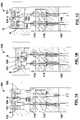
- FIG. 1Ais a cross-sectional schematic representation of a portion of a valve stem actuation system according to one embodiment, with valve stems in an open position;
- FIG. 1Bis the valve stem actuation system of FIG. 1A , with the valve stems in a closed position;
- FIG. 1Cis the valve stem actuation system of FIG. 1C , with one of the valve stems in a stuck position;
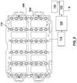
- FIG. 2is a bottom view of an actuation plate according to one embodiment
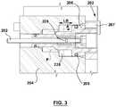
- FIG. 3is a cross-sectional schematic representation of a portion of a valve stem actuation system according to one embodiment
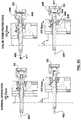
- FIG. 4is a cross-sectional schematic representation of a portion of a valve stem actuation system according to another embodiment
- FIGS. 5A-5Care cross-sectional schematic representations of a portion of a valve stem actuation system according to another embodiment
- FIGS. 6A and 6Bare cross-sectional schematic representations of a portion of a valve stem actuation system according to another embodiment.
- FIG. 7is an exploded perspective view of a portion of the valve stem actuation system according to another embodiment.
- Injection molding machinesare used to produce plastic molded parts.
- such machinesinclude a manifold that passes melted molding material, also referred to as melt, to nozzles that, in turn, pass the melt to individual mold cavities.
- meltmelted molding material
- the nozzlesinclude valve stems that reciprocate back and forth to open and close gates at the end of the nozzles.
- valve stemsmay be individually actuated, in some systems, it may be advantageous to simultaneously actuate all of the valve stems at the same time.
- the valve stemsmay be attached to an actuation plate that reciprocates back and forth to move the valve stems. With simultaneous actuation, if even a single valve stem fails (e.g., becomes stuck in a closed position), the injection molding machine must be shut off to correct the problem.
- individual actuationif a single valve stem fails, the single valve stem may be deactivated while the other valve stems may continue to be actuated.
- valve stemsmay be arranged to break or shear such that when a valve stem is stuck in the closed position, movement of the plate towards the open position causes the stuck valve stem to break.
- valve stemsmay be mechanically coupled to the plate via springs that are configured to push the valve stems into the open position (e.g., when an injection cycle has finished) and to compress if a valve stem become stuck in the closed position and the plate is moving towards the opened position.
- valve stemsmay be magnetically coupled to the actuation plate and may be configured to decouple from the plate if the valve stems become stuck.
- known systemsdo not provide a satisfactory solution in all respects.
- the hot runnermay continue to operate when one or more of the valve stems become stuck in the closed position.
- using pressurized air to maintain contact between the valve stem and the portion of the actuation platealso may allow the valve stem to be protected when the valve stem reciprocates between the open and closed positions and becomes stuck in the closed position and/or encounters an obstruction (e.g., in the mold the cavity).
- embodiments disclosed hereininclude a hot runner that uses pressurized air to hold the valve stems against the portion of the actuation plate, such as a retainer plate located at the back of the actuation plate, during plate actuation.
- Another technical effect of the air spring connectionmay include simplified hot runner startup. At startup, prior to start of a molding process, a calibration of the plate actuator must be completed. Calibration is done by cycling the actuation plate several times thereby repositioning the valve stems between closed and open positions. By virtue of the air spring connection the calibration can be done with the hot runner in either a cold or heated state. Specifically, the air supply to the air spring can be disabled to allow the operator to calibrate in either cold condition or hot condition for added convenience.
- valve stemsIn the hot condition with the air disabled, the valve stems will remain in closed position as the actuation plate is calibrated. Advantages of the foregoing may include reduced risk of drool flowing into the cavities because the valve stems remain closed thereby alleviating the additional requirement for the operator to remove solidified drool from cavities prior to startup of process and thereby save time.
- holding the valve stem against the portion of the actuation platemay mean that the valve stem (or an extension thereof) is pressed against the portion of the actuation plate or otherwise biased to a predetermined position relative thereto during plate actuation.
- the valve stemsmay directly contact the actuation plate.
- the valve stemsmay indirectly contact the actuation plate (e.g., via pistons).
- the valve stemmay be pressed in an upward direction relative to the actuation plate (i.e., towards the open position).
- holding the valve stem against the portion of the actuation platemay mean that the position of the valve stem is maintained relative to the position of the actuation plate during plate actuation.
- the hot runnerincludes air pistons that hold the valve stems against the portion of the actuation plate (e.g., against the retainer plate). That is, each valve stem may be coupled to an air piston, wherein the pressurized air A holds the piston against the portion of the actuation plate.
- the valve stemmay be coupled to the piston via any suitable method (e.g., a screw, magnet, slot connection, etc.).
- the pistonwill not be held against the portion of the actuation plate if the pressurized air is turned off.
- FIG. 1AAn example of a hot runner in an opened position, with valve stems held against a portion of the actuation plate (e.g., the retainer plate) via pressurized air applied to the corresponding air pistons, is illustrated in FIG. 1A , which will be discussed in more detail below.
- the pressurized airacts as an air spring.
- a threshold air pressureis applied to the air pistons.
- a threshold air pressuremay include an air pressure sufficient to produce a threshold force capable of holding the air pistons against the actuation plate (e.g., the retainer plate) during normal (e.g., an uninterrupted) operation of the hot runner. That is, the threshold force maintains contact between the piston and the portion of the actuation plate while the valve stem reciprocates between the open and closed positions.
- the threshold air pressureis between about 100 and 150 psi, although other suitable pressures may be used.
- the threshold air pressureis applied to the underside (e.g., a downstream side) of the air piston via air pressure channels in an air supply circuit formed in the actuation plate. That is, the pressure may be applied to the clamp side of the air pistons. In some embodiments, a seal is used to maintain the air pressure on the underside of the piston.
- the actuation platemoves towards the closed position (e.g., towards the gate) to cause the valves stems to block the flow of melt into a mold cavity.
- the actuation plate and associated retainer platepushes the air pistons, which moves the air pistons and valve stems, to the gates.
- the threshold forceholds the air pistons against the retainer plate as the actuation plate is moved towards the closed position.
- a distance that the valve stems travels between the open and closed positionsalso referred to as a stroke length L, see FIG. 1A , is about 15 mm.
- the actuation plateWhen the injection cycle has finished, the actuation plate returns to the open position.
- the valve stemscan move freely between the closed and open positions via actuation by the actuation plate.
- the threshold forceholds the pistons against the actuation plate and allows the actuation plate to pull the valve stems out of the gates. That is, the threshold force is greater than any holding force(s) exerted on the valve stems at the gate (e.g., a force generated by cooled melt in the mold or by another obstruction tending to prevent the valve stem from moving out of the gate).
- one or more of the valve stemsbecomes stuck in the closed position (e.g., stuck at the gate), as illustrated in FIG. 1C .
- the threshold force applied to the air pistoni.e., the pressurized air applied to the underside of the air piston
- the threshold forceis no longer sufficient to hold the piston against the actuation plate/retainer plate and pull the valve stem out of the gate. That is, the threshold force is less than the holding force exerted on the valve stem at the gate.
- the corresponding stuck pistonbecomes separated from the portion of the actuation plate (e.g., from the retainer plate) as the actuation plate moves towards the opened position.
- separation from the portion of the actuation platemay mean that pressurized air A no longer presses the piston against the portion of the actuation plate (e.g., the retainer plate). That is, the stuck piston no longer moves with movement of the actuation plate (e.g., the stuck piston does not reciprocate between the open and closed position). Instead, the actuation plate moves relative to the corresponding stuck valve stem and associated piston.
- the stuck pistonmay still remain within the actuation plate (e.g., within a piston bore in the actuation plate).
- valve stemsmay be stuck at the gate (e.g., when one or more of the mold cavities is down), the hot runner may still continue to move the unstuck pistons and valve stems between the open and closed positions. In such a situation, the threshold force applied to the unstuck valve stems by the pressurized air is still sufficient to hold the unstuck valve stems to the portion of the actuation plate during plate actuation.
- the stuck valve stems and associated air pistonsare maintained in the stationary position relative to the reciprocating actuation plate.
- the actuation platemay include piston bores that receive the air pistons. As the actuation plate reciprocates, the air piston remains stationary, being held by the stuck valve stem, within the piston bore.
- the pressurized air beneath the air pistonis simply compressed.
- the systemwhen one or more cavities are down (i.e., when one or more valve stems are stuck in the closed position), the system also may be stopped to allow for repairs. In such a situation, once the machine and pressurized air supply are turned off, the pistons may be separated from the actuation plate and may be removed for repair.
- FIGS. 1A-1Cillustrate an example of a hot runner 100 according to one aspect.
- both valve stems 102are pressed against the portion of the actuation plate via pressurized air A.
- the valve stems 102are coupled to pistons 106 , and pressurized air A holds (biases) the pistons upwardly (see the arrow labeled U) against a retainer plate 107 at the back of the actuation plate 104 .
- the pressurized air Atravels through air channels 108 in an air supply circuit formed in the actuation plate 104 .
- the hot runner 100also includes, amongst other things, a manifold 110 for passing melt from a sprue bushing (not shown) to the nozzles (not shown), a manifold-backing plate 112 , and a backing plate 114 .
- FIG. 1Bshows the actuation plate 104 in the closed position, after the actuation plate 104 has traveled a stroke length L (see FIG. 1A ) and the valve stems close the gate 105 (nozzle not shown). As with FIG. 1A , both valve stems are still pressed against the retainer plate 107 via pressurized air A acting on the pistons.
- FIG. 1Cillustrates the actuation plate 104 again in the open position, however, in this embodiment, one of the valve stems 102 s is stuck at the gate 105 .
- the holding force applied to the valve stem at the gateis greater than the threshold force pressing the valve stem 102 s /piston 106 s upwardly against the retainer plate 107 .
- the corresponding stuck air piston 106 sis connected to the stuck valve stem 102 s and is no longer pressed against the retainer plate 107 (see e.g., the space O between the piston 106 s and the retainer plate 107 ) and does not move with the movement of the actuation plate 104 .
- the unstuck valve stem 102is still pressed against the retainer plate 107 via its corresponding piston 106 and has travelled with the actuation plate 104 to the open position.
- the hot runnermay include one or more valve stems 102 .
- the actuation plate 104may be arranged to receive 48 valve stems and corresponding pistons. That is, the actuation plate 104 may have one or more drops 116 (e.g., 48 drops in FIG. 2 ), where the air pistons may be held against the actuation plate 104 (see FIG. 1 ).
- Other systemsmay include more or less drops, such as 24, 72, 96 or more.
- valve stemcan move upward to open the gate.
- pressurized airmay then be supplied to a top side of the piston.
- the piston 206may be held in contact with a retainer plate 207 .
- a seal 209is used to maintain the air pressure A in the cylinder/bore on the underside of the piston, as will be appreciated by those skilled in the art.
- the cylindermay be an air piston bore 226 formed in the actuation plate 204 .
- the seal(s) 209remains static, like an O-Ring seal, for example. In such embodiments, as the actuation plate moves, so do the air pistons 206 , which are pressed against the actuation plate via pressurized air.
- the seal 209acts as a sliding dynamic seal.
- the air supply circuitsupplies pressurized air A to each piston 104 via air channels 108 in the actuation plate 104 .
- all air channelsare in fluid communication with each other and with a source of air pressure.
- the actuation plate 104 and air channels 108are operatively connected to one or more pressure sensors 118 that detect a pressure in the circuit and/or at each of the drops.
- the pressure sensor(s)may provide feedback to a regulator 120 , which may regulate a supply S of pressurized air into the circuit via a valve 122 .
- the systemwill stop the molding process if the pressure sensor detects as loss of pressure during the molding process, that is below a specified set point.
- the sensorprotects the hotrunner from over pressurization. With a loss of air pressure, the pistons (and valve stems) could lag behind the motion of the actuation plate, and injection could occur with valve stems in closed or partially open position.
- the pressure sensorprevents system from injecting at start up, if air supply connection is not completed between machine and hotrunner.
- the valve 122is adjusted such that a threshold pressure may be maintained at each drop.
- the actuation plate 100is also operatively connected to a user interface 124 , which includes software and controls (not shown) that enable the operator to activate cavity down and cavity down maintenance functions.
- cavity downmay mean that the valve stem is stuck at the gate such that the cavity 109 may not be used for further injection molding.
- the air channels 108are formed by gun drilling bores or holes through the actuation plate along the desired paths and plugging the ends of the bores or holes with a plug.
- the actuation platealso may be manufactured according to other processes to create the necessary channels.
- the actuation platemay be formed by a split-and-bonded two-piece actuation plate (e.g., welding, brazing or diffusion bonding a two-piece actuation plate).
- the actuation platealso may be formed using solid free form fabrication, also known as additive manufacturing fabrication.
- the hot runnermay be configured to operate when a cavity 109 ( FIG. 1C ) is down (e.g., when the valve stem is stuck in the gate leading to the cavity). As will be described in more detail below, this may be accomplished by maintaining the position of the stuck piston when the corresponding valve stem is stuck at the gate as the plate moves. For example, the piston may remain within the actuation plate in the stuck position. In such embodiments, the actuation plate may continue to reciprocate without being held back by the stuck valve stem(s) and/or by the corresponding stuck piston(s).
- the actuating platemay include a piston bore 226 that receives the air piston 206 .
- the size and shape of the piston bore 226corresponds to the size and shape of the air piston 206 .
- a diameter of the piston boremay correspond to an outer diameter of the air piston 206 and be sized to accommodate the seal.
- the piston and piston boremay both be cylindrically shaped, although other suitable shapes may be used.
- the air piston 206is disposed within the piston bore 226 and is pressed against the retainer plate 207 via pressurized air A.
- the seal 209maintains the air pressure in the piston bore 226 on the underside of the piston.
- the pressurized air Ais on and generates the threshold force that exceeds the holding force, the air piston 206 may travel back and forth with the reciprocating movement of the actuating plate 204 .
- the pressurized air Ais turned off, the piston will no longer remain against the retainer plate 207 and the valve stem 202 will not reciprocate with movement of the actuation plate.
- the corresponding stuck pistoneffectively separates from the actuation plate, allowing the actuation plate to move and further compressing the air beneath the piston.
- the position of the stuck air pistonis illustrated by the dashed line labeled P.
- the stuck pistonis no longer pressed against the retainer plate 207 , however, the stuck piston still remain within the piston bore 226 .
- the piston bore 226is sized to accommodate the stuck and unstuck position of the air pistons 206 .
- the length of the bore LBis greater than a stroke length L to accommodate the stuck position P of the air piston 206 .
- the reciprocating actuation platemoves relative to the stuck air piston. That is, the piston bore 226 moves freely around the stuck air piston 206 when the actuation plate reciprocates back and forth. As a result, the hot runner may continue to operate without having to physically disconnect the piston from the actuation plate.
- the hot runnermay be configured to protect the valve stems by limiting the force that is applied to the valve stems.
- the valve stemmay be protected when the valve stem encounters an obstruction (e.g., a foreign body in the drop), that would otherwise overpower the force acting on the piston.
- an obstructione.g., a foreign body in the drop
- Examples of hot runners 100 with a valve stem protection mechanismcan be found in FIGS. 4 and 5A-5C .
- the hot runner 300may include a piston 340 with an air passageway 330 through which a supply of pressurized air S may pass into a chamber 341 , between the piston and the retainer plate 307 (e.g., the pressurized air is passed from the air channel 308 ).
- the chambermay be the air piston bore.
- the pressurized airbiases the valve stems towards the closed position (e.g., towards the gate). That is, with reference to FIG. 4 , air pressure D 1 may be used to push the piston/valve stem toward the closed position.
- air pressure D 1may be used to push the piston/valve stem toward the closed position.
- the systemprovides for the plate actuation to remain operative in the event the valve stem becomes stuck and/or encounters an obstruction.
- the hot runner 400may include a first piston 406 for valve stem actuation, as described above, that allows for continued plate actuation even when a valve stem become stuck at the gate.
- the hot runneralso may include a second piston 440 for valve stem protection, allowing for continued plate actuation even when the valve stem encounters an obstruction.
- the first piston 406may include an air piston 406 for holding the valve stem 402 against the retainer 407 via pressurized air A acting on the piston 406 as the actuation plate 404 reciprocates back and forth to drive the valve stem 402 .
- This first piston arrangementoperates in a manner described above with respect to FIGS. 1-3 .
- the second piston 440may be arranged similar to that of FIG. 4 .
- the second piston 440may be coupled to the air piston 406 and may extend through the retainer plate 404 . More specifically, the second piston 440 may include a shaft portion 442 that extends through the first air piston and is directly coupled to the valve stem 402 .
- the first piston 406also includes a shaft portion 444 surrounding the shaft 442 of the second piston 440 and extending through the actuation plate 404 .
- the first piston 406also includes a housing 446 formed on the piston and extending in a direction opposite the valve stem. This housing acts as the cylinder bore (e.g., see chamber 441 ) for the second piston 440 .
- This second pistonacts as a protection system to prevent damage to the valve stem if an obstruction 411 is preventing the valve stem from moving toward the closed position
- the air piston 406 and the protecting piston 440 of FIG. 5Ainclude air passageways 430 through which pressurized air passes from the air channels 408 into a chamber 441 .
- pressurized air Aacts on the first piston, holding the first piston 406 against the retainer 407
- pressurized air D 2acts on the second piston 440 , biasing the second piston 440 towards the closed position.
- the retainerpushes on the first piston 406 and the air pressure D 2 acts on the second piston 440 .
- the air acting on the air piston 406(e.g., the air in the piston bore 426 ) is allowed to simply compress, as shown in FIG. 5B , as the actuation plate 406 moves to the open position. Specifically, the actuation plate 404 moves to the open position while the first piston 406 , housing and valve stem 402 remains stationary.
- the actuation platewill still continue to push on the retainer 407 , which in turn pushes the piston 406 and valve stem 402 .
- the first piston 406is configured to pull on the housing when the actuation plate moves towards the closed position, which will compress the air acting on the second piston (e.g., the air in the chamber 441 ).
- the second pistone.g., the air in the chamber 441 .
- the hot runner 500may include a spring 550 to provide valve stem 502 protection.
- the spring 550may be used to protect the valve stem during the purging process of a multi-material hot runner when an unmelt of molding material blocks the gate.
- a secondary (e.g., barrier) molding material in barrier channels of the nozzlesusing a reverse flow of primary (e.g., skin) molding material (e.g., from the inner and/or outer flow channels of the nozzle).
- the valve stemsare retracted into a back position, a short shot (e.g., a partial shot) of the primary molding material is injected through the nozzle into the molding cavity, and the melt is allowed to solidify.
- the solidified meltforms a short (e.g., partially) molded article that plugs the gate.
- the plugredirects the flow into the secondary (e.g., barrier) channels of the nozzle to complete the purge.
- the solidified plugsmust be removed from the respective gates.
- valve stemsmay be subjected to an abnormal (e.g., high) closing force that may shear the safety pins that couples the valve stems to the air pistons.
- an abnormal closing forcee.g., high
- the spring 550may be used to protect the valve stem in other applications such as, for example, a monolayer PET systems (i.e. the molding of preforms of the type for blow molding into containers that are molded entirely of PET material without layers).
- a monolayer PET systemsi.e. the molding of preforms of the type for blow molding into containers that are molded entirely of PET material without layers.
- melt droolis able to solidify to produce a localized ‘gate nub’ (i.e. partial molding in the region of the gate channel).
- the technicianmanually removes these gate nubs to allow plastic to fill the cavity as the solidified nubs cannot be ejected or re-melted by the next shot.
- valve stem 502is coupled to the air piston 506 , which, in turn, is held in contact with the retainer plate 507 via pressurized air A travelling through the air channels 508 .
- the air piston 506is received in and moves relative to the air piston bore 526 formed in the actuation plate 504 .
- a seal 509may be used to maintain the air pressure A in piston bore 526 .
- the air piston 506includes a housing 546 that includes a bore (see, e.g., cylinder 541 ) in which the spring 550 is housed.
- the spring 550is coupled to the proximal end of the valve stem 502 via a valve stem assembly 553 (see also the exploded perspective view of FIG. 7 ).
- the valve stem assembly 553may include a valve stem head 554 that is received in a sleeve 556 of a valve stem retainer 558 .
- the valve stem assemblyalso includes a shear pin 560 that connects the valve stem head 554 to the spring 552 .
- the shear pin 560may be removably attached to the valve stem head 554 in some embodiment, although it also may be permanently attached.
- the valve stem assemblyalso may be housed in the cylinder 541 of the air piston 506 . As shown in FIG. 6A , a spring cap 551 is screwed into the housing to close the cylinder, holding the spring 550 therein.
- the spring 552in a normal operating position, the spring 552 is held in between the valve stem retainer and the spring cap 552 , and travels back and forth during plate actuation. As will be appreciated, in such a normal operating position, the spring may be preloaded to a specific force to ensure that pressure cannot force the valve stem backwards and create a tall gate. In some embodiments, the spring 552 biases the valve stem towards the piston. In some embodiments, a gap G is maintained between the valve stem retainer 558 and the air piton 506 , which allows the valve stem 502 to float within the air piston 506 . In some embodiments, the gap is between about 0.01 and 0.5 mm.
- FIG. 6Billustrates an embodiment in which the valve stem 502 encounters an obstruction 562 that stops valve stem 502 movement.
- the actuation plate 504has continued to move towards the gate, which, in turn, pushes the piston 506 and valve stem 502 .
- the spring 550may be compressed as the actuation plate 504 moves towards the closed position. Without wishing to be bound by theory, compressing the spring may limit the force exerted on the valve stem via the obstruction.
- compressing the springallows the valve stem to remain stationary with respect to the actuation plate 404 .
- the gap Gincreases as the spring compresses.
- the air pressure Ais still sufficient to keep the piston 506 pressed against the retainer plate 507 .
- the hot runnermay be configured to maintain and/or to extend the life of the seals used.
- the actuation platemay be cycled prior to starting up in a maintenance mode, with all nozzles tip heaters off. All valve stems and pistons may then be locked in the closed positions by the solidified drops. The machine may then turn off the air supply to the actuation plate and vent to the atmosphere. The actuation plate may then cycle back and forth to work the seals in the air piston. After this maintenance, the machine may resume normal system operation.
- the hot runnermay be configured to shut down if the machine senses a drop in pressure. For example, if a loss of pressure is detected (e.g., the pressurized air supply S is decreased), the machine may sound an alarm and stop the molding cycle. As will be appreciated, the molding machine may be stopped to ensure that the machine does not inject with all or some of the valve stems in the closed position or if they lag behind, or if the gates are not fully open. In some embodiments, this pressure monitoring may mitigate the risk of injecting on closed valve stems and over pressurizing (e.g., an internal leak) the hot runner.
- a loss of pressuree.g., the pressurized air supply S is decreased
- the molding machinemay be stopped to ensure that the machine does not inject with all or some of the valve stems in the closed position or if they lag behind, or if the gates are not fully open.
- this pressure monitoringmay mitigate the risk of injecting on closed valve stems and over pressurizing (e.g., an internal leak) the
- valve stembeing held against the actuation plate via air pistons, (that is, the air pistons are held against the actuation plate via air pressure)
- the head of the valve stemitself may be pressed against the retainer plate. That is, a valve pin head 303 of the valve pin may be held against the actuation plate via air pressure and disposed within a bore via suitable seals.
Landscapes
- Engineering & Computer Science (AREA)
- Manufacturing & Machinery (AREA)
- Mechanical Engineering (AREA)
- Moulds For Moulding Plastics Or The Like (AREA)
- Injection Moulding Of Plastics Or The Like (AREA)
Abstract
Description
Claims (11)
Priority Applications (1)
| Application Number | Priority Date | Filing Date | Title |
|---|---|---|---|
| US15/773,824US10882233B2 (en) | 2015-11-23 | 2016-11-14 | Valve stem actuation |
Applications Claiming Priority (4)
| Application Number | Priority Date | Filing Date | Title |
|---|---|---|---|
| US201562258704P | 2015-11-23 | 2015-11-23 | |
| US201662290252P | 2016-02-02 | 2016-02-02 | |
| PCT/CA2016/051317WO2017088044A1 (en) | 2015-11-23 | 2016-11-14 | Valve stem actuation |
| US15/773,824US10882233B2 (en) | 2015-11-23 | 2016-11-14 | Valve stem actuation |
Related Parent Applications (1)
| Application Number | Title | Priority Date | Filing Date |
|---|---|---|---|
| PCT/CA2016/051317A-371-Of-InternationalWO2017088044A1 (en) | 2015-11-23 | 2016-11-14 | Valve stem actuation |
Related Child Applications (1)
| Application Number | Title | Priority Date | Filing Date |
|---|---|---|---|
| US17/099,858DivisionUS11667066B2 (en) | 2015-11-23 | 2020-11-17 | Valve stem actuation |
Publications (2)
| Publication Number | Publication Date |
|---|---|
| US20180326635A1 US20180326635A1 (en) | 2018-11-15 |
| US10882233B2true US10882233B2 (en) | 2021-01-05 |
Family
ID=58762798
Family Applications (2)
| Application Number | Title | Priority Date | Filing Date |
|---|---|---|---|
| US15/773,824Active2036-12-15US10882233B2 (en) | 2015-11-23 | 2016-11-14 | Valve stem actuation |
| US17/099,858Active2037-07-25US11667066B2 (en) | 2015-11-23 | 2020-11-17 | Valve stem actuation |
Family Applications After (1)
| Application Number | Title | Priority Date | Filing Date |
|---|---|---|---|
| US17/099,858Active2037-07-25US11667066B2 (en) | 2015-11-23 | 2020-11-17 | Valve stem actuation |
Country Status (6)
| Country | Link |
|---|---|
| US (2) | US10882233B2 (en) |
| EP (1) | EP3380296B1 (en) |
| JP (2) | JP6791978B2 (en) |
| CN (1) | CN108367474B (en) |
| CA (1) | CA3004591C (en) |
| WO (1) | WO2017088044A1 (en) |
Cited By (1)
| Publication number | Priority date | Publication date | Assignee | Title |
|---|---|---|---|---|
| US20220126492A1 (en)* | 2020-10-27 | 2022-04-28 | Mold-Masters (2007) Limited | Valve pin plate injection molding apparatus |
Families Citing this family (1)
| Publication number | Priority date | Publication date | Assignee | Title |
|---|---|---|---|---|
| US10882233B2 (en)* | 2015-11-23 | 2021-01-05 | Husky Injection Molding Systems Ltd. | Valve stem actuation |
Citations (51)
| Publication number | Priority date | Publication date | Assignee | Title |
|---|---|---|---|---|
| US3892512A (en) | 1973-09-13 | 1975-07-01 | Alan V Diehl | Transfer molding apparatus with resilient pad to distribute molding pressure |
| US4443178A (en) | 1981-07-30 | 1984-04-17 | Toshiba Kikai Kabushiki Kaisha | Valve nozzle devices |
| FR2537497A1 (en) | 1982-12-09 | 1984-06-15 | Manner Otto | Injection moulding needle valve |
| EP0021273B1 (en) | 1979-06-12 | 1984-09-12 | Hendrikus Jacobus Elisabeth Schouenberg | Injection mechanism for molding plastics |
| US5078589A (en) | 1990-06-15 | 1992-01-07 | Osuna Diaz J M | Multicavity injection molding apparatus having precision adjustment and shut off of injection flow to individual mold cavities |
| WO1992013700A1 (en) | 1991-02-12 | 1992-08-20 | Seiki Corporation | Improved hot runner mold arrangement and use thereof |
| US5375994A (en) | 1992-02-29 | 1994-12-27 | Otto Manner | Piston driven pin closure nozzle assembly |
| US5660369A (en) | 1993-07-09 | 1997-08-26 | Incoe Corporation | Pneumatic control device for needle valves in injection molding systems |
| DE19611880A1 (en) | 1996-03-26 | 1997-10-02 | Zahoransky Formenbau Gmbh | Hot runner injection mould using shut-off needles |
| US6062840A (en) | 1997-09-02 | 2000-05-16 | Dynisco Hotrunners, Inc. | Hot runner system for coinjection molding |
| US6113381A (en) | 1999-02-08 | 2000-09-05 | Mold-Masters Limited | Injection molding valve member actuating mechanism |
| DE19943797A1 (en) | 1999-09-13 | 2001-03-15 | Yudo Co | Polymer injection system for an injection molding system, has single piston feeding polymer to all injection nozzles |
| US6343921B1 (en) | 1998-04-21 | 2002-02-05 | Synventive Molding Solutions | Manifold system having flow control using separate cavities |
| EP1426160A1 (en) | 2002-12-03 | 2004-06-09 | Mold-Masters Limited | Hot runner co-injection nozzle |
| US6755641B1 (en) | 2000-09-01 | 2004-06-29 | Mold-Masters Limited | Stack injection molding apparatus with separately actuated arrays of valve gates |
| US20050046083A1 (en) | 2003-08-29 | 2005-03-03 | Neil Dewar | Multi-position valve pin for an injection molding apparatus |
| FR2829058B1 (en) | 2001-09-06 | 2005-05-13 | Delachaux Sa | METHOD AND DEVICE FOR INJECTING A THERMOPLASTIC MATERIAL IN AN IMPRESSION OF A MOLD |
| US7014455B2 (en) | 2002-03-14 | 2006-03-21 | Mold-Masters Limited | Valve-gated injection molding system with side-mounted actuator |
| US7022278B2 (en) | 2002-02-11 | 2006-04-04 | Mold-Masters Limited | Valve pin locking mechanism |
| US7125246B2 (en) | 2003-10-08 | 2006-10-24 | Mold Hotrunner Solutions Inc. | Hot runner for molding small plastic articles |
| KR100655750B1 (en) | 2005-11-16 | 2006-12-13 | 김혁중 | Elastic valve system for injection molding |
| US7210922B1 (en)* | 2004-11-18 | 2007-05-01 | Tech Mold, Inc. | Valve pin operating mechanism |
| US7341688B2 (en) | 2004-11-19 | 2008-03-11 | Husky Injection Molding Systems Ltd. | Valve gate for a hot runner injection molding machine |
| US7553150B2 (en) | 2006-06-19 | 2009-06-30 | Mold-Masters (2007) Limited | Valve-pin actuating device for a hot runner apparatus |
| JP2009160844A (en) | 2008-01-08 | 2009-07-23 | Mold-Masters (2007) Ltd | Simultaneous injection molding apparatus and hot runner nozzle related to the same |
| US20090220636A1 (en) | 2006-01-10 | 2009-09-03 | Herbert Gunther | Actuating Device for Shut-Off Needles in Injection Molding Machines Having Needle Valve Nozzles |
| US7713046B2 (en) | 2006-10-13 | 2010-05-11 | Mold-Masters (2007) Limited | Injection molding apparatus having movable yoke plate |
| US20100124579A1 (en)* | 2008-11-18 | 2010-05-20 | Mold-Masters (2007) Limited | Injection Molding Apparatus Having A Valve Pin Coupling |
| US7722351B2 (en) | 2007-10-22 | 2010-05-25 | Mold-Masters (2007) Limited | Injection molding apparatus having magnetic valve pin coupling |
| US7766646B2 (en) | 2007-06-22 | 2010-08-03 | Mold-Masters (2007) Limited | Injection molding apparatus with plate actuation of valve pins |
| US7815431B2 (en) | 2005-12-28 | 2010-10-19 | Gunther Heisskanaltechnik Gmbh | Actuating device for shut-off needles in injection molding devices comprising needle shut-off nozzles |
| US7866975B2 (en) | 2006-01-02 | 2011-01-11 | Gunther Heisskanaltechnik Gmbh | Operating device for shut-off needles in injection-moulding devices with needle valve nozzles |
| US7931455B2 (en) | 2008-10-10 | 2011-04-26 | Mold-Masters (2007) Limited | Injection molding apparatus having magnetic valve pin coupling |
| CN201863357U (en) | 2010-11-17 | 2011-06-15 | 柳道万和(苏州)热流道系统有限公司 | Hot runner system |
| US7988445B2 (en) | 2008-08-21 | 2011-08-02 | Mold-Masters (2077) Limited | Injection molding apparatus having a nozzle tip component for taking a nozzle out-of-service |
| US20110304075A1 (en) | 2008-08-04 | 2011-12-15 | Mold-Masters (2007) Limited | Breakable Mechanical Connection Between Injection Molding Valve Pin Plate and Valve Pins |
| US8100689B2 (en) | 2009-10-09 | 2012-01-24 | Husky Injection Molding Systems Ltd. | Safety connector for hot runner, having latch releasably interlocking valve stem with actuation plate |
| US8220362B2 (en) | 2007-10-23 | 2012-07-17 | Husky Injection Molding Systems Ltd. | Cam apparatus for valve stem actuation |
| CN202367911U (en) | 2011-12-21 | 2012-08-08 | 柳道万和(苏州)热流道系统有限公司 | Synchronous valve needle driving device for hot runner system |
| US8282870B2 (en) | 2008-03-24 | 2012-10-09 | Husky Injection Molding Systems Ltd. | Safety connector for hot runner, having latch destructively interlocking valve stem with actuation plate |
| US8308476B2 (en) | 2011-03-01 | 2012-11-13 | Mold-Masters (2007) Limited | Injection molding apparatus having a magnetic valve pin coupling |
| WO2012173955A1 (en) | 2011-06-15 | 2012-12-20 | Husky Injection Molding Systems Ltd | Molding system including stationary platen positioned between actuation assembly and stem-actuation plate |
| DE102011106606A1 (en) | 2011-06-16 | 2012-12-20 | Psg Plastic Service Gmbh | Device for simultaneously actuating shut-off needles in plastic injection molding machine for manufacturing plastic mold parts, has lifting plate displaceably supported at bifurcated frame in transverse to traveling direction of needles |
| US8393889B2 (en) | 2009-04-21 | 2013-03-12 | Husky Injection Molding Systems Ltd | Hot-runner system having valve stem movable responsive to electro-magnetic actuator |
| WO2013074741A1 (en) | 2011-11-18 | 2013-05-23 | Husky Injection Molding Systems Ltd. | Mold-tool system including stem-compliance assembly |
| US20140327173A1 (en) | 2011-11-15 | 2014-11-06 | Husky Molding Systems Ltd. a corporation | Reducing crown flash in injection-molding processes |
| US8920155B2 (en) | 2013-03-15 | 2014-12-30 | Caco Pacific Corporation | Locking apparatus for common plate stem actuator |
| US20150014887A1 (en) | 2012-02-27 | 2015-01-15 | Otto Manner Innovation Gmbh | Hot runner system |
| US8985997B2 (en) | 2012-03-02 | 2015-03-24 | Mold-Masters (2007) Limited | Valve bushing for an injection molding apparatus |
| US20150151473A1 (en) | 2012-07-12 | 2015-06-04 | Otto Männer Innovation GmbH | Injection molding apparatus with active valve pin disengagement |
| US20150158227A1 (en) | 2012-05-31 | 2015-06-11 | Synventive Molding Solutions, Inc. | Injection molding flow control apparatus and method |
Family Cites Families (16)
| Publication number | Priority date | Publication date | Assignee | Title |
|---|---|---|---|---|
| JP2612795B2 (en)* | 1992-06-15 | 1997-05-21 | 世紀株式会社 | Runnerless injection molding equipment |
| US5374182A (en)* | 1992-09-30 | 1994-12-20 | Husky Injection Molding Systems Ltd. | Hot runner manifold bushing |
| CA2111248C (en)* | 1993-12-13 | 2002-05-07 | Alex C. Teng | Valve gated injection molding apparatus with a spring in the piston |
| JP3022433U (en)* | 1995-09-06 | 1996-03-26 | 世紀株式会社 | Valve gate device for injection mold |
| US6343925B1 (en)* | 2000-04-14 | 2002-02-05 | Husky Injection Molding Systems, Ltd. | Hot runner valve gate piston assembly |
| CA2437076C (en)* | 2002-08-14 | 2010-10-12 | Mold-Masters Limited | Valve pin adjustment device |
| KR100529839B1 (en)* | 2003-12-09 | 2005-11-23 | 김혁중 | linear valve system for injection molding machine |
| DE102005017413B4 (en)* | 2005-04-15 | 2008-06-26 | Otto Männer Innovation GmbH | Injection nozzle with two outlet openings |
| KR200404991Y1 (en)* | 2005-10-22 | 2006-01-10 | 김혁중 | Valve device for injection molding machine |
| ITRM20060499A1 (en)* | 2006-09-20 | 2008-03-21 | Sipa Societa Industrializzazione E Progettazione | SHUTTER ROD |
| JP5514585B2 (en)* | 2010-03-04 | 2014-06-04 | 世紀株式会社 | Piston device with a mechanism for limiting the pressing force of a valve pin for opening and closing a valve gate in an injection molding machine |
| US8591220B2 (en)* | 2011-03-04 | 2013-11-26 | Terry L. Schwenk | Valve pin and actuator assembly for injection molding |
| JP5930741B2 (en)* | 2012-02-01 | 2016-06-08 | 世紀株式会社 | Split valve pin |
| JP5747849B2 (en)* | 2012-03-26 | 2015-07-15 | 東レ株式会社 | Gate valve and method for manufacturing gate valve |
| JP2017030155A (en)* | 2015-07-29 | 2017-02-09 | 株式会社尾関ホットランナープラン | Injection molding device |
| US10882233B2 (en)* | 2015-11-23 | 2021-01-05 | Husky Injection Molding Systems Ltd. | Valve stem actuation |
- 2016
- 2016-11-14USUS15/773,824patent/US10882233B2/enactiveActive
- 2016-11-14CACA3004591Apatent/CA3004591C/enactiveActive
- 2016-11-14CNCN201680064914.1Apatent/CN108367474B/enactiveActive
- 2016-11-14EPEP16867474.5Apatent/EP3380296B1/enactiveActive
- 2016-11-14JPJP2018545532Apatent/JP6791978B2/enactiveActive
- 2016-11-14WOPCT/CA2016/051317patent/WO2017088044A1/ennot_activeCeased
- 2020
- 2020-09-23JPJP2020158504Apatent/JP6983293B2/enactiveActive
- 2020-11-17USUS17/099,858patent/US11667066B2/enactiveActive
Patent Citations (56)
| Publication number | Priority date | Publication date | Assignee | Title |
|---|---|---|---|---|
| US3892512A (en) | 1973-09-13 | 1975-07-01 | Alan V Diehl | Transfer molding apparatus with resilient pad to distribute molding pressure |
| EP0021273B1 (en) | 1979-06-12 | 1984-09-12 | Hendrikus Jacobus Elisabeth Schouenberg | Injection mechanism for molding plastics |
| US4443178A (en) | 1981-07-30 | 1984-04-17 | Toshiba Kikai Kabushiki Kaisha | Valve nozzle devices |
| FR2537497A1 (en) | 1982-12-09 | 1984-06-15 | Manner Otto | Injection moulding needle valve |
| US5078589A (en) | 1990-06-15 | 1992-01-07 | Osuna Diaz J M | Multicavity injection molding apparatus having precision adjustment and shut off of injection flow to individual mold cavities |
| WO1992013700A1 (en) | 1991-02-12 | 1992-08-20 | Seiki Corporation | Improved hot runner mold arrangement and use thereof |
| US5375994A (en) | 1992-02-29 | 1994-12-27 | Otto Manner | Piston driven pin closure nozzle assembly |
| US5660369A (en) | 1993-07-09 | 1997-08-26 | Incoe Corporation | Pneumatic control device for needle valves in injection molding systems |
| DE19611880A1 (en) | 1996-03-26 | 1997-10-02 | Zahoransky Formenbau Gmbh | Hot runner injection mould using shut-off needles |
| US6062840A (en) | 1997-09-02 | 2000-05-16 | Dynisco Hotrunners, Inc. | Hot runner system for coinjection molding |
| US6343921B1 (en) | 1998-04-21 | 2002-02-05 | Synventive Molding Solutions | Manifold system having flow control using separate cavities |
| JP2002513687A (en) | 1998-04-21 | 2002-05-14 | ダイニスコ・ホットラナーズ・インコーポレーテッド | Manifold mechanism with flow control function |
| US6113381A (en) | 1999-02-08 | 2000-09-05 | Mold-Masters Limited | Injection molding valve member actuating mechanism |
| DE19943797A1 (en) | 1999-09-13 | 2001-03-15 | Yudo Co | Polymer injection system for an injection molding system, has single piston feeding polymer to all injection nozzles |
| US6755641B1 (en) | 2000-09-01 | 2004-06-29 | Mold-Masters Limited | Stack injection molding apparatus with separately actuated arrays of valve gates |
| US7086852B2 (en) | 2000-09-01 | 2006-08-08 | Mold-Masters Limited | Stack injection molding apparatus with separately actuated arrays of valve gates |
| FR2829058B1 (en) | 2001-09-06 | 2005-05-13 | Delachaux Sa | METHOD AND DEVICE FOR INJECTING A THERMOPLASTIC MATERIAL IN AN IMPRESSION OF A MOLD |
| US7022278B2 (en) | 2002-02-11 | 2006-04-04 | Mold-Masters Limited | Valve pin locking mechanism |
| US7014455B2 (en) | 2002-03-14 | 2006-03-21 | Mold-Masters Limited | Valve-gated injection molding system with side-mounted actuator |
| EP1426160A1 (en) | 2002-12-03 | 2004-06-09 | Mold-Masters Limited | Hot runner co-injection nozzle |
| US20050046083A1 (en) | 2003-08-29 | 2005-03-03 | Neil Dewar | Multi-position valve pin for an injection molding apparatus |
| US7125246B2 (en) | 2003-10-08 | 2006-10-24 | Mold Hotrunner Solutions Inc. | Hot runner for molding small plastic articles |
| US7210922B1 (en)* | 2004-11-18 | 2007-05-01 | Tech Mold, Inc. | Valve pin operating mechanism |
| US7341688B2 (en) | 2004-11-19 | 2008-03-11 | Husky Injection Molding Systems Ltd. | Valve gate for a hot runner injection molding machine |
| KR100655750B1 (en) | 2005-11-16 | 2006-12-13 | 김혁중 | Elastic valve system for injection molding |
| US7815431B2 (en) | 2005-12-28 | 2010-10-19 | Gunther Heisskanaltechnik Gmbh | Actuating device for shut-off needles in injection molding devices comprising needle shut-off nozzles |
| US7866975B2 (en) | 2006-01-02 | 2011-01-11 | Gunther Heisskanaltechnik Gmbh | Operating device for shut-off needles in injection-moulding devices with needle valve nozzles |
| US20090220636A1 (en) | 2006-01-10 | 2009-09-03 | Herbert Gunther | Actuating Device for Shut-Off Needles in Injection Molding Machines Having Needle Valve Nozzles |
| US7553150B2 (en) | 2006-06-19 | 2009-06-30 | Mold-Masters (2007) Limited | Valve-pin actuating device for a hot runner apparatus |
| US7713046B2 (en) | 2006-10-13 | 2010-05-11 | Mold-Masters (2007) Limited | Injection molding apparatus having movable yoke plate |
| US7766646B2 (en) | 2007-06-22 | 2010-08-03 | Mold-Masters (2007) Limited | Injection molding apparatus with plate actuation of valve pins |
| US8142182B2 (en) | 2007-10-22 | 2012-03-27 | Mold-Master (2007) Limited | Injection molding apparatus having a magnetic valve pin coupling |
| US7722351B2 (en) | 2007-10-22 | 2010-05-25 | Mold-Masters (2007) Limited | Injection molding apparatus having magnetic valve pin coupling |
| US8465688B2 (en) | 2007-10-22 | 2013-06-18 | Mold-Masters (2007) Limited | Method of taking a nozzle of a valve gated hot runner apparatus out of service |
| US8220362B2 (en) | 2007-10-23 | 2012-07-17 | Husky Injection Molding Systems Ltd. | Cam apparatus for valve stem actuation |
| JP2009160844A (en) | 2008-01-08 | 2009-07-23 | Mold-Masters (2007) Ltd | Simultaneous injection molding apparatus and hot runner nozzle related to the same |
| US8282870B2 (en) | 2008-03-24 | 2012-10-09 | Husky Injection Molding Systems Ltd. | Safety connector for hot runner, having latch destructively interlocking valve stem with actuation plate |
| US20110304075A1 (en) | 2008-08-04 | 2011-12-15 | Mold-Masters (2007) Limited | Breakable Mechanical Connection Between Injection Molding Valve Pin Plate and Valve Pins |
| US7988445B2 (en) | 2008-08-21 | 2011-08-02 | Mold-Masters (2077) Limited | Injection molding apparatus having a nozzle tip component for taking a nozzle out-of-service |
| US7931455B2 (en) | 2008-10-10 | 2011-04-26 | Mold-Masters (2007) Limited | Injection molding apparatus having magnetic valve pin coupling |
| US7963762B2 (en) | 2008-11-18 | 2011-06-21 | Mold-Masters (2007) Limited | Injection molding apparatus having a valve pin coupling |
| US20100124579A1 (en)* | 2008-11-18 | 2010-05-20 | Mold-Masters (2007) Limited | Injection Molding Apparatus Having A Valve Pin Coupling |
| US8393889B2 (en) | 2009-04-21 | 2013-03-12 | Husky Injection Molding Systems Ltd | Hot-runner system having valve stem movable responsive to electro-magnetic actuator |
| US8100689B2 (en) | 2009-10-09 | 2012-01-24 | Husky Injection Molding Systems Ltd. | Safety connector for hot runner, having latch releasably interlocking valve stem with actuation plate |
| CN201863357U (en) | 2010-11-17 | 2011-06-15 | 柳道万和(苏州)热流道系统有限公司 | Hot runner system |
| US8308476B2 (en) | 2011-03-01 | 2012-11-13 | Mold-Masters (2007) Limited | Injection molding apparatus having a magnetic valve pin coupling |
| WO2012173955A1 (en) | 2011-06-15 | 2012-12-20 | Husky Injection Molding Systems Ltd | Molding system including stationary platen positioned between actuation assembly and stem-actuation plate |
| DE102011106606A1 (en) | 2011-06-16 | 2012-12-20 | Psg Plastic Service Gmbh | Device for simultaneously actuating shut-off needles in plastic injection molding machine for manufacturing plastic mold parts, has lifting plate displaceably supported at bifurcated frame in transverse to traveling direction of needles |
| US20140327173A1 (en) | 2011-11-15 | 2014-11-06 | Husky Molding Systems Ltd. a corporation | Reducing crown flash in injection-molding processes |
| WO2013074741A1 (en) | 2011-11-18 | 2013-05-23 | Husky Injection Molding Systems Ltd. | Mold-tool system including stem-compliance assembly |
| CN202367911U (en) | 2011-12-21 | 2012-08-08 | 柳道万和(苏州)热流道系统有限公司 | Synchronous valve needle driving device for hot runner system |
| US20150014887A1 (en) | 2012-02-27 | 2015-01-15 | Otto Manner Innovation Gmbh | Hot runner system |
| US8985997B2 (en) | 2012-03-02 | 2015-03-24 | Mold-Masters (2007) Limited | Valve bushing for an injection molding apparatus |
| US20150158227A1 (en) | 2012-05-31 | 2015-06-11 | Synventive Molding Solutions, Inc. | Injection molding flow control apparatus and method |
| US20150151473A1 (en) | 2012-07-12 | 2015-06-04 | Otto Männer Innovation GmbH | Injection molding apparatus with active valve pin disengagement |
| US8920155B2 (en) | 2013-03-15 | 2014-12-30 | Caco Pacific Corporation | Locking apparatus for common plate stem actuator |
Non-Patent Citations (3)
| Title |
|---|
| European Search Report, Raicher, Gerald, dated Jun. 5, 2019, 5 pages. |
| PCT International Search Report; Zhang, Pengfei; Jan. 16, 2017; 5 pages. |
| Woodford, Chris. "Gas Springs". (Jul. 15, 2015) https://web.archive.org/web/20151031085012/https://www.explainthatstuff.com/gassprings.html (Year: 2015).* |
Cited By (2)
| Publication number | Priority date | Publication date | Assignee | Title |
|---|---|---|---|---|
| US20220126492A1 (en)* | 2020-10-27 | 2022-04-28 | Mold-Masters (2007) Limited | Valve pin plate injection molding apparatus |
| US11766817B2 (en)* | 2020-10-27 | 2023-09-26 | Mold-Masters (2007) Limited | Valve pin plate injection molding apparatus |
Also Published As
| Publication number | Publication date |
|---|---|
| JP6983293B2 (en) | 2021-12-17 |
| JP6791978B2 (en) | 2020-11-25 |
| CA3004591A1 (en) | 2017-06-01 |
| US20180326635A1 (en) | 2018-11-15 |
| US20210069953A1 (en) | 2021-03-11 |
| EP3380296B1 (en) | 2020-03-18 |
| CA3004591C (en) | 2022-07-05 |
| US11667066B2 (en) | 2023-06-06 |
| CN108367474B (en) | 2020-10-23 |
| CN108367474A (en) | 2018-08-03 |
| EP3380296A4 (en) | 2019-07-17 |
| JP2020199779A (en) | 2020-12-17 |
| JP2019502577A (en) | 2019-01-31 |
| EP3380296A1 (en) | 2018-10-03 |
| WO2017088044A1 (en) | 2017-06-01 |
Similar Documents
| Publication | Publication Date | Title |
|---|---|---|
| EP2214883B1 (en) | Valve-gated hot runner system having reduced valve-stem drool | |
| US7931455B2 (en) | Injection molding apparatus having magnetic valve pin coupling | |
| US11667066B2 (en) | Valve stem actuation | |
| US7963762B2 (en) | Injection molding apparatus having a valve pin coupling | |
| US20130251843A1 (en) | Valve gate system | |
| US20040197437A1 (en) | Hot runner nozzle with melt sealing | |
| US9302416B1 (en) | Single nozzle valve gate | |
| CA2837637C (en) | Injection molding nozzle with dynamic seal | |
| US8734146B2 (en) | Miniature automatic shutoff nozzle tip | |
| US7824175B2 (en) | Injection molding anti-drool nozzle | |
| US7678320B2 (en) | Anti-drool mechanism for a sprue bushing | |
| US6558148B1 (en) | Gas valve pin mechanism | |
| AU2002232474B2 (en) | Gas valve pin mechanism | |
| US20060121155A1 (en) | Nozzle and apparatus for injection molding | |
| AU2002232474A1 (en) | Gas valve pin mechanism | |
| JP2005324501A (en) | Injection nozzle device for resin material | |
| JP2003071878A (en) | Mold for injection molding |
Legal Events
| Date | Code | Title | Description |
|---|---|---|---|
| AS | Assignment | Owner name:HUSKY INJECTION MOLDING SYSTEMS LTD., CANADA Free format text:ASSIGNMENT OF ASSIGNORS INTEREST;ASSIGNORS:FERENC, STEPHEN DANIEL, MR;KEIR, WILLIAM STEVEN, MR;WHITE, BRANDON DOUGLAS, MR;SIGNING DATES FROM 20151124 TO 20160105;REEL/FRAME:045719/0643 | |
| FEPP | Fee payment procedure | Free format text:ENTITY STATUS SET TO UNDISCOUNTED (ORIGINAL EVENT CODE: BIG.); ENTITY STATUS OF PATENT OWNER: LARGE ENTITY | |
| STPP | Information on status: patent application and granting procedure in general | Free format text:APPLICATION UNDERGOING PREEXAM PROCESSING | |
| STPP | Information on status: patent application and granting procedure in general | Free format text:DOCKETED NEW CASE - READY FOR EXAMINATION | |
| STPP | Information on status: patent application and granting procedure in general | Free format text:NON FINAL ACTION MAILED | |
| STPP | Information on status: patent application and granting procedure in general | Free format text:NON FINAL ACTION MAILED | |
| STPP | Information on status: patent application and granting procedure in general | Free format text:FINAL REJECTION MAILED | |
| STPP | Information on status: patent application and granting procedure in general | Free format text:ADVISORY ACTION MAILED | |
| STPP | Information on status: patent application and granting procedure in general | Free format text:DOCKETED NEW CASE - READY FOR EXAMINATION | |
| STPP | Information on status: patent application and granting procedure in general | Free format text:PUBLICATIONS -- ISSUE FEE PAYMENT RECEIVED | |
| STCF | Information on status: patent grant | Free format text:PATENTED CASE | |
| AS | Assignment | Owner name:DEUTSCHE BANK AG NEW YORK BRANCH, AS COLLATERAL AGENT, NEW YORK Free format text:SECURITY AGREEMENT;ASSIGNOR:HUSKY INJECTION MOLDING SYSTEMS LTD.;REEL/FRAME:067202/0708 Effective date:20240423 | |
| AS | Assignment | Owner name:WILMINGTON TRUST, NATIONAL ASSOCIATION, AS NOTES COLLATERAL AGENT, MINNESOTA Free format text:PATENT SECURITY AGREEMENT (NOTES);ASSIGNOR:HUSKY INJECTION MOLDING SYSTEMS LTD.;REEL/FRAME:067204/0757 Effective date:20240423 | |
| FEPP | Fee payment procedure | Free format text:SURCHARGE FOR LATE PAYMENT, LARGE ENTITY (ORIGINAL EVENT CODE: M1554); ENTITY STATUS OF PATENT OWNER: LARGE ENTITY | |
| MAFP | Maintenance fee payment | Free format text:PAYMENT OF MAINTENANCE FEE, 4TH YEAR, LARGE ENTITY (ORIGINAL EVENT CODE: M1551); ENTITY STATUS OF PATENT OWNER: LARGE ENTITY Year of fee payment:4 |