US10881472B2 - Correcting a robotic surgery user interface device tracking input - Google Patents
Correcting a robotic surgery user interface device tracking inputDownload PDFInfo
- Publication number
- US10881472B2 US10881472B2US15/900,552US201815900552AUS10881472B2US 10881472 B2US10881472 B2US 10881472B2US 201815900552 AUS201815900552 AUS 201815900552AUS 10881472 B2US10881472 B2US 10881472B2
- Authority
- US
- United States
- Prior art keywords
- sample
- lqe
- uid
- output
- tracking input
- Prior art date
- Legal status (The legal status is an assumption and is not a legal conclusion. Google has not performed a legal analysis and makes no representation as to the accuracy of the status listed.)
- Active, expires
Links
Images


Classifications
- A—HUMAN NECESSITIES
- A61—MEDICAL OR VETERINARY SCIENCE; HYGIENE
- A61B—DIAGNOSIS; SURGERY; IDENTIFICATION
- A61B34/00—Computer-aided surgery; Manipulators or robots specially adapted for use in surgery
- A61B34/30—Surgical robots
- A61B34/32—Surgical robots operating autonomously
- A—HUMAN NECESSITIES
- A61—MEDICAL OR VETERINARY SCIENCE; HYGIENE
- A61B—DIAGNOSIS; SURGERY; IDENTIFICATION
- A61B34/00—Computer-aided surgery; Manipulators or robots specially adapted for use in surgery
- A61B34/20—Surgical navigation systems; Devices for tracking or guiding surgical instruments, e.g. for frameless stereotaxis
- A—HUMAN NECESSITIES
- A61—MEDICAL OR VETERINARY SCIENCE; HYGIENE
- A61B—DIAGNOSIS; SURGERY; IDENTIFICATION
- A61B34/00—Computer-aided surgery; Manipulators or robots specially adapted for use in surgery
- A61B34/30—Surgical robots
- A—HUMAN NECESSITIES
- A61—MEDICAL OR VETERINARY SCIENCE; HYGIENE
- A61B—DIAGNOSIS; SURGERY; IDENTIFICATION
- A61B34/00—Computer-aided surgery; Manipulators or robots specially adapted for use in surgery
- A61B34/70—Manipulators specially adapted for use in surgery
- A61B34/74—Manipulators with manual electric input means
- B—PERFORMING OPERATIONS; TRANSPORTING
- B25—HAND TOOLS; PORTABLE POWER-DRIVEN TOOLS; MANIPULATORS
- B25J—MANIPULATORS; CHAMBERS PROVIDED WITH MANIPULATION DEVICES
- B25J13/00—Controls for manipulators
- B25J13/08—Controls for manipulators by means of sensing devices, e.g. viewing or touching devices
- B25J13/088—Controls for manipulators by means of sensing devices, e.g. viewing or touching devices with position, velocity or acceleration sensors
- B—PERFORMING OPERATIONS; TRANSPORTING
- B25—HAND TOOLS; PORTABLE POWER-DRIVEN TOOLS; MANIPULATORS
- B25J—MANIPULATORS; CHAMBERS PROVIDED WITH MANIPULATION DEVICES
- B25J15/00—Gripping heads and other end effectors
- B25J15/0019—End effectors other than grippers
- B—PERFORMING OPERATIONS; TRANSPORTING
- B25—HAND TOOLS; PORTABLE POWER-DRIVEN TOOLS; MANIPULATORS
- B25J—MANIPULATORS; CHAMBERS PROVIDED WITH MANIPULATION DEVICES
- B25J3/00—Manipulators of leader-follower type, i.e. both controlling unit and controlled unit perform corresponding spatial movements
- B—PERFORMING OPERATIONS; TRANSPORTING
- B25—HAND TOOLS; PORTABLE POWER-DRIVEN TOOLS; MANIPULATORS
- B25J—MANIPULATORS; CHAMBERS PROVIDED WITH MANIPULATION DEVICES
- B25J9/00—Programme-controlled manipulators
- B25J9/16—Programme controls
- B25J9/1602—Programme controls characterised by the control system, structure, architecture
- B25J9/161—Hardware, e.g. neural networks, fuzzy logic, interfaces, processor
- B—PERFORMING OPERATIONS; TRANSPORTING
- B25—HAND TOOLS; PORTABLE POWER-DRIVEN TOOLS; MANIPULATORS
- B25J—MANIPULATORS; CHAMBERS PROVIDED WITH MANIPULATION DEVICES
- B25J9/00—Programme-controlled manipulators
- B25J9/16—Programme controls
- B25J9/1628—Programme controls characterised by the control loop
- B25J9/163—Programme controls characterised by the control loop learning, adaptive, model based, rule based expert control
- B—PERFORMING OPERATIONS; TRANSPORTING
- B25—HAND TOOLS; PORTABLE POWER-DRIVEN TOOLS; MANIPULATORS
- B25J—MANIPULATORS; CHAMBERS PROVIDED WITH MANIPULATION DEVICES
- B25J9/00—Programme-controlled manipulators
- B25J9/16—Programme controls
- B25J9/1628—Programme controls characterised by the control loop
- B25J9/1653—Programme controls characterised by the control loop parameters identification, estimation, stiffness, accuracy, error analysis
- B—PERFORMING OPERATIONS; TRANSPORTING
- B25—HAND TOOLS; PORTABLE POWER-DRIVEN TOOLS; MANIPULATORS
- B25J—MANIPULATORS; CHAMBERS PROVIDED WITH MANIPULATION DEVICES
- B25J9/00—Programme-controlled manipulators
- B25J9/16—Programme controls
- B25J9/1679—Programme controls characterised by the tasks executed
- B25J9/1689—Teleoperation
- G—PHYSICS
- G06—COMPUTING OR CALCULATING; COUNTING
- G06F—ELECTRIC DIGITAL DATA PROCESSING
- G06F3/00—Input arrangements for transferring data to be processed into a form capable of being handled by the computer; Output arrangements for transferring data from processing unit to output unit, e.g. interface arrangements
- G06F3/01—Input arrangements or combined input and output arrangements for interaction between user and computer
- G06F3/03—Arrangements for converting the position or the displacement of a member into a coded form
- G06F3/033—Pointing devices displaced or positioned by the user, e.g. mice, trackballs, pens or joysticks; Accessories therefor
- G06F3/0346—Pointing devices displaced or positioned by the user, e.g. mice, trackballs, pens or joysticks; Accessories therefor with detection of the device orientation or free movement in a 3D space, e.g. 3D mice, 6-DOF [six degrees of freedom] pointers using gyroscopes, accelerometers or tilt-sensors
- G—PHYSICS
- G06—COMPUTING OR CALCULATING; COUNTING
- G06F—ELECTRIC DIGITAL DATA PROCESSING
- G06F3/00—Input arrangements for transferring data to be processed into a form capable of being handled by the computer; Output arrangements for transferring data from processing unit to output unit, e.g. interface arrangements
- G06F3/01—Input arrangements or combined input and output arrangements for interaction between user and computer
- G06F3/03—Arrangements for converting the position or the displacement of a member into a coded form
- G06F3/033—Pointing devices displaced or positioned by the user, e.g. mice, trackballs, pens or joysticks; Accessories therefor
- G06F3/038—Control and interface arrangements therefor, e.g. drivers or device-embedded control circuitry
- A—HUMAN NECESSITIES
- A61—MEDICAL OR VETERINARY SCIENCE; HYGIENE
- A61B—DIAGNOSIS; SURGERY; IDENTIFICATION
- A61B34/00—Computer-aided surgery; Manipulators or robots specially adapted for use in surgery
- A61B34/10—Computer-aided planning, simulation or modelling of surgical operations
- A61B2034/101—Computer-aided simulation of surgical operations
- A61B2034/102—Modelling of surgical devices, implants or prosthesis
- A61B2034/104—Modelling the effect of the tool, e.g. the effect of an implanted prosthesis or for predicting the effect of ablation or burring
- A—HUMAN NECESSITIES
- A61—MEDICAL OR VETERINARY SCIENCE; HYGIENE
- A61B—DIAGNOSIS; SURGERY; IDENTIFICATION
- A61B34/00—Computer-aided surgery; Manipulators or robots specially adapted for use in surgery
- A61B34/20—Surgical navigation systems; Devices for tracking or guiding surgical instruments, e.g. for frameless stereotaxis
- A61B2034/2046—Tracking techniques
- A61B2034/2048—Tracking techniques using an accelerometer or inertia sensor
- A—HUMAN NECESSITIES
- A61—MEDICAL OR VETERINARY SCIENCE; HYGIENE
- A61B—DIAGNOSIS; SURGERY; IDENTIFICATION
- A61B34/00—Computer-aided surgery; Manipulators or robots specially adapted for use in surgery
- A61B34/20—Surgical navigation systems; Devices for tracking or guiding surgical instruments, e.g. for frameless stereotaxis
- A61B2034/2046—Tracking techniques
- A61B2034/2051—Electromagnetic tracking systems
- A—HUMAN NECESSITIES
- A61—MEDICAL OR VETERINARY SCIENCE; HYGIENE
- A61B—DIAGNOSIS; SURGERY; IDENTIFICATION
- A61B34/00—Computer-aided surgery; Manipulators or robots specially adapted for use in surgery
- A61B34/20—Surgical navigation systems; Devices for tracking or guiding surgical instruments, e.g. for frameless stereotaxis
- A61B2034/2046—Tracking techniques
- A61B2034/2055—Optical tracking systems
- B—PERFORMING OPERATIONS; TRANSPORTING
- B25—HAND TOOLS; PORTABLE POWER-DRIVEN TOOLS; MANIPULATORS
- B25J—MANIPULATORS; CHAMBERS PROVIDED WITH MANIPULATION DEVICES
- B25J9/00—Programme-controlled manipulators
- B25J9/16—Programme controls
- B25J9/1656—Programme controls characterised by programming, planning systems for manipulators
- B25J9/1664—Programme controls characterised by programming, planning systems for manipulators characterised by motion, path, trajectory planning
- G—PHYSICS
- G05—CONTROLLING; REGULATING
- G05B—CONTROL OR REGULATING SYSTEMS IN GENERAL; FUNCTIONAL ELEMENTS OF SUCH SYSTEMS; MONITORING OR TESTING ARRANGEMENTS FOR SUCH SYSTEMS OR ELEMENTS
- G05B2219/00—Program-control systems
- G05B2219/30—Nc systems
- G05B2219/40—Robotics, robotics mapping to robotics vision
- G05B2219/40161—Visual display of machining, operation, remote viewing
- G—PHYSICS
- G05—CONTROLLING; REGULATING
- G05B—CONTROL OR REGULATING SYSTEMS IN GENERAL; FUNCTIONAL ELEMENTS OF SUCH SYSTEMS; MONITORING OR TESTING ARRANGEMENTS FOR SUCH SYSTEMS OR ELEMENTS
- G05B2219/00—Program-control systems
- G05B2219/30—Nc systems
- G05B2219/40—Robotics, robotics mapping to robotics vision
- G05B2219/40195—Tele-operation, computer assisted manual operation
- Y—GENERAL TAGGING OF NEW TECHNOLOGICAL DEVELOPMENTS; GENERAL TAGGING OF CROSS-SECTIONAL TECHNOLOGIES SPANNING OVER SEVERAL SECTIONS OF THE IPC; TECHNICAL SUBJECTS COVERED BY FORMER USPC CROSS-REFERENCE ART COLLECTIONS [XRACs] AND DIGESTS
- Y10—TECHNICAL SUBJECTS COVERED BY FORMER USPC
- Y10S—TECHNICAL SUBJECTS COVERED BY FORMER USPC CROSS-REFERENCE ART COLLECTIONS [XRACs] AND DIGESTS
- Y10S901/00—Robots
- Y10S901/02—Arm motion controller
- Y—GENERAL TAGGING OF NEW TECHNOLOGICAL DEVELOPMENTS; GENERAL TAGGING OF CROSS-SECTIONAL TECHNOLOGIES SPANNING OVER SEVERAL SECTIONS OF THE IPC; TECHNICAL SUBJECTS COVERED BY FORMER USPC CROSS-REFERENCE ART COLLECTIONS [XRACs] AND DIGESTS
- Y10—TECHNICAL SUBJECTS COVERED BY FORMER USPC
- Y10S—TECHNICAL SUBJECTS COVERED BY FORMER USPC CROSS-REFERENCE ART COLLECTIONS [XRACs] AND DIGESTS
- Y10S901/00—Robots
- Y10S901/30—End effector
- Y10S901/41—Tool
- Y—GENERAL TAGGING OF NEW TECHNOLOGICAL DEVELOPMENTS; GENERAL TAGGING OF CROSS-SECTIONAL TECHNOLOGIES SPANNING OVER SEVERAL SECTIONS OF THE IPC; TECHNICAL SUBJECTS COVERED BY FORMER USPC CROSS-REFERENCE ART COLLECTIONS [XRACs] AND DIGESTS
- Y10—TECHNICAL SUBJECTS COVERED BY FORMER USPC
- Y10S—TECHNICAL SUBJECTS COVERED BY FORMER USPC CROSS-REFERENCE ART COLLECTIONS [XRACs] AND DIGESTS
- Y10S901/00—Robots
- Y10S901/46—Sensing device
Definitions
- An embodiment of the inventionrelates to digital signal processing techniques for correcting a sensor circuit-generated signal that tracks the orientation or position of a handheld, robotic surgery user interface device. Other embodiments are also described.
- a user interface devicesuch as a handheld manipulator (held in the surgeon's hand) are translated into corresponding movements of a joint on a robotic or manipulator arm to which a surgical tool is attached (also referred to as end effector.)
- a surgical toolalso referred to as end effector.
- a digital stream of sensed orientation data and position datathat may be time-stamped or that may be updated regularly according to a clock signal, is produced by a sensor subsystem.
- the streamrepresents real-time tracking of the UIDs orientation and position, also referred to as robotic surgery UID tracking (orientation and position) data.
- a part or all of the sensor subsystemmay be inside the housing of the UID, e.g., using the raw output from inertial sensors such as an accelerometer and a gyro that are inside the UID housing.
- the UID tracking datamay also be produced by a sensor subsystem such as a six-degree of freedom (6DOF) electromagnetic tracker that is suitable for medical or surgical applications, or by an optical tracker that is “looking” at markers on the UID.
- the tracking datamay be relative (e.g., incremental displacement or orientation changes) or it may be absolute.
- the tracking datais an input to a robotic surgery controller that translates the tracking data, which is a direct measure of the movement of the UID, into corresponding actuator commands for an end effector, so that the end effector mimics the movements of the UID (that are caused by for example the surgeon's hand, wrist and fingers.)
- the tracking datatilt input
- the tracking datais noisy or imprecise, and therefore needs to be corrected in order to ensure precision and repeatability in the movement of the end effector.
- the tracking inputmay be time-stamped or it may be isochronous, its constituent measured values (measured samples) might have been produced or delivered by the sensor circuit at a different rate than desired by the robotic surgery controller that is consuming the tracking input, e.g., the sensor circuit sampling rate may be slower than the sample rate of a discrete time domain (digital) controller.
- An embodiment of the inventionis a linear quadratic estimator, LQE, that corrects a noisy or imprecise robotic surgery UID tracking input, and may also inherently up-sample the tracking input to come closer to or match the higher input sample rate of a robotic surgery control system controller, and may do so without introducing an unduly high latency.
- the LQE(or corrector) integrates the latency reduction and up-sampling functions into its prediction phase that is repeating at a higher rate than the UID tracking input to produce output samples, and switches to its update phase when a new tracking input sample is received.
- a Kalman filter gainmay be computed that is used to compute an updated output sample of the LQE.
- a latency coefficient used in the prediction phasehas been tuned in advance, so that the LQE output exhibits reduced latency.
- a robotic surgery systemhas a processor and a machine-readable medium having stored therein instructions that when executed by the processor correct a UID tracking input, by producing an output sequence that is an estimate of a position or an orientation of the UID.
- the processorreceives an input sequence that are measures of the position or the orientation of the UID, and computes a current output sample of the output sequence, wherein the current output sample is computed based on i) a previously computed output sample, and ii) a velocity term.
- a new tracking input sample of the input sequenceis received, a new output sample of the output sequence is computed, based on i) a previously computed output sample, and ii) the new tracking input sample.
- the instructionsare such that while the new tracking input sample has not been received, the current output sample in the output sequence is computed from a window of several previously computed output samples, by a) fitting a line to the previously computed output samples in the window, and b) taking a slope of the line to be the velocity term.
- FIG. 1is a block diagram of an example robotic surgery system.
- FIG. 2is a flow diagram of a linear quadratic estimation process.
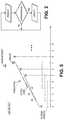
- FIG. 3is an example plot of LQE output samples overlaid with tracking input measurement samples.
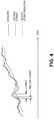
- FIG. 4depicts example plots of a tracking input (measured), overlaid with a low pass filtered version and an LQE processed version.
- FIG. 5is an example plot of prediction values that are computed using a sliding window and using fitted lines.
- a conventional linear quadratic estimator, LQEhas a prediction phase in which a system model is used to compute estimates of an output state variable (also referred to here as “output”), and an update phase in which the outcome of the present input measurement (which is of course corrupted by noise or imprecision) is used to update the estimates so that they tend to be more precise than the input measurements.
- the LQEs algorithmis recursive and can run in real time, using only the present input measurements and the previously calculated output (and its uncertainty matrix.)
- FIG. 1is a block diagram of an example robotic surgery system 1 in which the modified LQE, LQE 6 , is used.
- the movements of a user interface device, UID 4such as a handheld manipulator (held in the surgeon's hand) are translated into corresponding movements of a joint on a robotic or manipulator arm to which a surgical tool is attached, also referred to here as an end effector 3 .
- a digital stream of sensed orientation data and position datais produced by a UID tracking subsystem 5 .
- the streamrepresents real-time tracking of the orientation and position of the UID 4 , also referred to as robotic surgery UID tracking data (orientation data, position data, or both.)
- a part or all of the UID tracking subsystem 5may be inside the housing of the UID 4 , e.g., using the raw output from inertial sensors such as an accelerometer and a gyro that are inside the UID housing.
- the UID tracking datamay also be produced by a sensor subsystem such as a six-degree of freedom (6DOF) electromagnetic tracker that is suitable for medical or surgical applications, or by an optical tracker that is “looking” at markers on the UID 4 .
- the tracking datamay be relative (e.g., incremental displacement or orientation changes) or it may be absolute.
- the tracking datais an input to a feedback control system controller 8 that translates the tracking data, which is a direct measure of the movement of the UID 4 , into corresponding actuator commands for an end effector 3 , so that the end effector 3 mimics the movements of the UID 4 (that are caused by for example the surgeon's hand, wrist and fingers.)
- a feedback control system controller 8that translates the tracking data, which is a direct measure of the movement of the UID 4 , into corresponding actuator commands for an end effector 3 , so that the end effector 3 mimics the movements of the UID 4 (that are caused by for example the surgeon's hand, wrist and fingers.)
- the tracking input produced by the UID tracking subsystem 5is noisy or imprecise, and therefore needs to be corrected in order to ensure precision and repeatability in the movement of the end effector 3 .
- the tracking inputmay be time-stamped or it may be isochronous, its constituent measured values (measured samples) may have been produced or delivered by the sensor circuit (in the subsystem 5 ) at a different rate than desired by the controller 8 that is consuming the tracking input, e.g., the sensor circuit sampling rate may be slower than the sample rate of a discrete time domain (digital) controller.
- a linear quadratic estimator, LQE 6is thus provided to correct the tracking input.
- the LQE 6may be described as having a prediction phase and an update phase, which together recursively compute the samples of an LQE state variable (output), such as position, in accordance with the flow diagram of FIG. 2 .
- LQE state variableoutput
- FIG. 2may produce the example discrete time sequence shown in FIG. 3 , where operation begins with a current (or next) sample of the output state variable of the LQE (e.g., an output vector containing position values, orientation values, or both) being computed in the prediction phase, as a “prediction” at sample 1.
- the LQE 6produces its output samples 2-5 by repeating its prediction phase four times, until a new tracking input sample Xmeas is received in between sample 5 and sample 6 (“measurement”.)
- the algorithmswitches to its update phase in which an updated output “update” is computed at sample 6.
- the processthen resumes with the prediction phase which is repeated to produce samples 7-11 until another new tracking input sample arrives in between sample 11 and sample 12, the latter causing a switch to the update phase to compute another updated output at sample 12.
- the next output samples 13-17are produced in the prediction phase, followed with another updated output sample 18.
- sample 1there may be an initialization stage in which the initial output state value (sample 1) is computed based on an input state (the tracking input or a measurement) or other initial condition, following which the next output state variable (sample 2 and subsequent samples) are computed recursively based on a previously computed output state value.
- the prediction phase of the LQE 6may be illustrated using the following example of a constant velocity mathematical system model, for position variable X.
- V0previous velocity
- t0
- the LQE 6may alternatively be applied to correct just the orientation data, while a non-estimating type low pass filter, e.g., a digital finite impulse response, FIR, filter, is applied to reduce noise in the position data only.
- delta_tmay refer to the time interval used in the system model to compute a current sample at index n+1 from a previous sample at index n, in the prediction phase (it is not the tracking input's sampling period, which is lower than the rate at which predictions are computed in the prediction phase.) It can be seen from Eq.
- the computation of X[n+1]relies on two primary terms, namely delta_t and a computation of the velocity term V both of which are described below in turn.
- the velocity term Vhere is not a “state” of the LQE as is X, but rather an input or external term.
- the noise termit may be assumed to be Gaussian noise with zero mean and a sigma standard deviation.
- the update phasemay use any conventional measurement model (that is applicable to the UID and its tracking data) to compute an updated output, Xupd (an “update” data point in FIG. 2 .)
- Xmeasis the position (x-y-z) measurement or tracking input and X[n+1] is the predicted state calculated in Eq. 2.
- the measurement noise termmay be modeled by collecting UID position data (tracking input) at different positions and orientations of the UID 4 and then by calculating its histogram.
- the update phasemay proceed as follows: compare Xmeas with Xpred (e.g., a previously computed output, X[n+1]), and use a measure of that comparison to compute a Kalman gain, K, using a particular measurement model; if the difference between Xmeas and Xpred is large, then K becomes larger, and if the difference is small then K becomes smaller.
- Xupdmay then be taken as the updated, current output sample of the LQE (in this example, X[n+1].)
- the modified LQEmay then proceed with computing the next output sample, here X[n+2], using its prediction phase operations as described above, and until another new tracking input is received that triggers the update phase. Up-Sampling
- the up-sampling of the tracking input by the modified LQEhappens inherently when repeating the prediction phase at a higher rate than the tracking input sampling.
- Computation of X as the output staterepeats until a new (e.g., a most recent) tracking input sample Xmeas arrives—see FIG. 3 .
- the up-sampling functionmay be viewed as being performed during the prediction phase, according to the decision loop depicted in FIG. 2 : if there is no new tracking input sample, then predict the output state, and then repeat that prediction until there is a new tracking input sample at which point the output state is updated in accordance with the new tracking input sample (e.g., and in accordance with a new Kalman filter gain.)
- a further advantage of the above processis that the prediction and update phases may occur asynchronously, which allows up sampling to be performed as needed to fill in the “gap” between adjacent tracking input samples. For instance, in FIG. 3 , it can be seen that the first three series of consecutive predicted outputs (preceding the first three measurements) are each five samples long, whereas the fourth series is only three samples long (because the fourth measurement arrived sooner in that instance.)
- a tuning parameteralso referred to here as a latency coefficient, alpha
- nominal_periodis the nominal LQE output sampling period and is the same (constant) for a batch of UIDs and their respective tracking input correctors
- alphais a tuning parameter that varies from specimen to specimen of that batch.
- the nominal_period1 msec
- alphais a fraction of the nominal_period but may vary depending on the application (the particular UID and its sensor-generated tracking input.)
- the latency coefficient alphashould be adjusted during a “calibration process”, e.g., at the factory, for each production UID specimen, until the LQE output (which is being computed in accordance with the prediction and update phases as described further below) properly predicts “what is going to happen”, by effectively shifting the LQE output sequence earlier in time, closer to the tracking input.
- a “calibration process”e.g., at the factory
- the LQE outputwhich is being computed in accordance with the prediction and update phases as described further below
- FIG. 4where it can be seen that alpha has been varied until the output of the LQE 6 during a given trajectory of the particular specimen of the UID is shifted to the left, to lie “on top” of the measured signal (UID tracking input.)
- FIG. 4where it can be seen that alpha has been varied until the output of the LQE 6 during a given trajectory of the particular specimen of the UID is shifted to the left, to lie “on top” of the measured signal (UID
- Vmay be computed from a window of previously computed output samples, X[n ⁇ 1], X[n ⁇ 2], . . . X[n ⁇ k] by fitting a line to the sequence of k output samples in the window, and then taking the slope of that line to be the velocity V.
- the fitted linemay be defined by a continuous polynomial, which may be of first order so as to define a straight line as shown in the figure, or it may be of a higher order which defines a curved line.
- This parameterization of the position variable X with respect to time, to yield a continuous line and then determine the slope of the line, e.g., its derivative,is an advantageous feature because it inherently results in a smooth velocity estimate, V.
- the position datamay include x, y and z values, such that A and B may be 3 ⁇ 1 vectors representing the polynomial coefficients for the three direction, x, y and z.
- the length k of the window(the number of samples in it) may be viewed as a second calibration parameter that can be used when tuning the latency coefficient alpha (see above.) Also, the window of length k moves or slides as shown in FIG. 5 , each time the prediction phase is repeated to make a new prediction (e.g., the last k position values will change as shown), and so the computed velocity V changes for each prediction.
- system model used in the prediction phaseneed not change and may remain the same for every prediction, while the window of state values that are used to parameterize the position state variable (and compute the velocity) does move in time and so changes with each new prediction.
- the quaternion estimatesare parameterized with respect to time and their derivatives are taken.
- q ( q 0, q 1, t )q 0*sin [(1 ⁇ t ) ⁇ ]/sin( ⁇ )+ q 1*sin[ t ⁇ ]/sin( ⁇ ) (9)
- q 1q [ n ] (10)
- the UID tracking inputis used to update the quaternion orientation estimates.
- the measurement noise termmay be modeled similar to the position case. Additional Thoughts
- orientation elementssuch as (pitch, yaw, roll) or quaternion (3 angles, and 1 length) are not all independent from each other and as such need an estimating-type filter like the LQE 6 described above for the orientation case.
- an embodiment of the inventionmay be an article of manufacture in which a machine-readable medium (such as microelectronic memory) has stored therein instructions which program one or more data processing components (generically referred to here as “a processor” that executes the instructions) to perform the digital signal processing operations of the LQE 6 described above for correcting the UID tracking input.
- a machine-readable mediumsuch as microelectronic memory
- a processorthat executes the instructions
- some of these operationsmight be performed by specific hardware components that contain hardwired logic (e.g., dedicated digital filter blocks and state machines). Those operations might alternatively be performed by any combination of programmed data processing components and fixed hardwired circuit components.
Landscapes
- Engineering & Computer Science (AREA)
- Health & Medical Sciences (AREA)
- Robotics (AREA)
- Surgery (AREA)
- Life Sciences & Earth Sciences (AREA)
- Mechanical Engineering (AREA)
- Heart & Thoracic Surgery (AREA)
- Biomedical Technology (AREA)
- Medical Informatics (AREA)
- Molecular Biology (AREA)
- Animal Behavior & Ethology (AREA)
- General Health & Medical Sciences (AREA)
- Public Health (AREA)
- Veterinary Medicine (AREA)
- Nuclear Medicine, Radiotherapy & Molecular Imaging (AREA)
- General Engineering & Computer Science (AREA)
- Theoretical Computer Science (AREA)
- Physics & Mathematics (AREA)
- Human Computer Interaction (AREA)
- General Physics & Mathematics (AREA)
- Automation & Control Theory (AREA)
- Artificial Intelligence (AREA)
- Evolutionary Computation (AREA)
- Fuzzy Systems (AREA)
- Mathematical Physics (AREA)
- Software Systems (AREA)
- Manipulator (AREA)
- Image Analysis (AREA)
Abstract
Description
X=X0+|V0*t+|½*A*t2 (1)
X[n+1]=X[n]+V*delta_t+noise (2)
This equation may be used to compute the state variable X at time index n+1 (also referred to as a current output sample X[n+1]). That computation is based on i) a previously computed output sample X[n], ii) a computed velocity term V, and iii) an inter-sample time interval delta_t (that as described below has been adjusted by a tuning parameter, alpha.) Note that delta_t may refer to the time interval used in the system model to compute a current sample at index n+1 from a previous sample at index n, in the prediction phase (it is not the tracking input's sampling period, which is lower than the rate at which predictions are computed in the prediction phase.) It can be seen from Eq. 2 above that in addition to the previous estimate of the state X[n], the computation of X[n+1] relies on two primary terms, namely delta_t and a computation of the velocity term V both of which are described below in turn. Also, the velocity term V here is not a “state” of the LQE as is X, but rather an input or external term. As to the noise term, it may be assumed to be Gaussian noise with zero mean and a sigma standard deviation.
Update Phase
Xmeas=X[n+1]+noise (3)
Xupd=Xpred+K*( . . . ) (4)
where known techniques can be used to compute the K*( . . . ) term. Xupd may then be taken as the updated, current output sample of the LQE (in this example, X[n+1].) The modified LQE may then proceed with computing the next output sample, here X[n+2], using its prediction phase operations as described above, and until another new tracking input is received that triggers the update phase.
Up-Sampling
delta_t=nominal_period+alpha (5)
Note that nominal_period is the nominal LQE output sampling period and is the same (constant) for a batch of UIDs and their respective tracking input correctors, while alpha is a tuning parameter that varies from specimen to specimen of that batch. For example, the nominal_period=1 msec, and alpha is a fraction of the nominal_period but may vary depending on the application (the particular UID and its sensor-generated tracking input.)
X(t)=A*t+B (6)
dX(t)/dt=V(t)=A (7)
q[n+1]=exp(½*skew(w*(nominal_period+latency_parameter)))*q[n]+noise (8)
where q is a 4×1 quaternion vector, w is a 3×1 angular velocity vector around x, y, or z axis, and is used as an input term not as a state variable, skew( ) is the skew symmetric matrix operation, nominal_period is the nominal LQE output sampling period as described above in connection with Eq. 5, and latency_parameter is a tuning parameter (like alpha above) to account for latency. The noise term may again be assumed to be Gaussian noise with zero mean and sigma standard deviation.
q(q0,q1,t)=q0*sin [(1−t)Ω]/sin(Ω)+q1*sin[tΩ]/sin(Ω) (9)
where q0 and q1 are 4×1 quaternion vectors corresponding to the estimated quaternions, window_length outputs before and the last output, respectively, as given by
q0=q[n−window_length]q1=q[n] (10)
q_dot=dq/dt (11)
w=2*transpose(Q(q[n]))*q_dot (12)
where Q is a 4×3 matrix formed by the latest quaternion estimate q[n] and it is calculated as
q_uid=q[n+1]+noise (14)
where q_uid is the quaternion measurement (UID tracking input) and q[n+1] is the predicted state calculated in Eq. 8. The measurement noise term may be modeled similar to the position case.
Additional Thoughts
Claims (18)
Priority Applications (6)
| Application Number | Priority Date | Filing Date | Title |
|---|---|---|---|
| US15/900,552US10881472B2 (en) | 2018-02-20 | 2018-02-20 | Correcting a robotic surgery user interface device tracking input |
| PCT/US2018/019774WO2019164533A1 (en) | 2018-02-20 | 2018-02-26 | Correcting a robotic surgery user interface device tracking input |
| EP18907327.3AEP3755257B1 (en) | 2018-02-20 | 2018-02-26 | Correcting a robotic surgery user interface device tracking input |
| US17/110,928US11413101B2 (en) | 2018-02-20 | 2020-12-03 | Correcting a robotic surgery user interface device tracking input |
| US17/878,670US11883119B2 (en) | 2018-02-20 | 2022-08-01 | Correcting a robotic surgery user interface device tracking input |
| US18/408,332US12433704B2 (en) | 2018-02-20 | 2024-01-09 | Correcting a robotic surgery user interface device tracking input |
Applications Claiming Priority (1)
| Application Number | Priority Date | Filing Date | Title |
|---|---|---|---|
| US15/900,552US10881472B2 (en) | 2018-02-20 | 2018-02-20 | Correcting a robotic surgery user interface device tracking input |
Related Child Applications (1)
| Application Number | Title | Priority Date | Filing Date |
|---|---|---|---|
| US17/110,928DivisionUS11413101B2 (en) | 2018-02-20 | 2020-12-03 | Correcting a robotic surgery user interface device tracking input |
Publications (2)
| Publication Number | Publication Date |
|---|---|
| US20190254761A1 US20190254761A1 (en) | 2019-08-22 |
| US10881472B2true US10881472B2 (en) | 2021-01-05 |
Family
ID=67617417
Family Applications (4)
| Application Number | Title | Priority Date | Filing Date |
|---|---|---|---|
| US15/900,552Active2038-11-26US10881472B2 (en) | 2018-02-20 | 2018-02-20 | Correcting a robotic surgery user interface device tracking input |
| US17/110,928ActiveUS11413101B2 (en) | 2018-02-20 | 2020-12-03 | Correcting a robotic surgery user interface device tracking input |
| US17/878,670ActiveUS11883119B2 (en) | 2018-02-20 | 2022-08-01 | Correcting a robotic surgery user interface device tracking input |
| US18/408,332ActiveUS12433704B2 (en) | 2018-02-20 | 2024-01-09 | Correcting a robotic surgery user interface device tracking input |
Family Applications After (3)
| Application Number | Title | Priority Date | Filing Date |
|---|---|---|---|
| US17/110,928ActiveUS11413101B2 (en) | 2018-02-20 | 2020-12-03 | Correcting a robotic surgery user interface device tracking input |
| US17/878,670ActiveUS11883119B2 (en) | 2018-02-20 | 2022-08-01 | Correcting a robotic surgery user interface device tracking input |
| US18/408,332ActiveUS12433704B2 (en) | 2018-02-20 | 2024-01-09 | Correcting a robotic surgery user interface device tracking input |
Country Status (3)
| Country | Link |
|---|---|
| US (4) | US10881472B2 (en) |
| EP (1) | EP3755257B1 (en) |
| WO (1) | WO2019164533A1 (en) |
Cited By (8)
| Publication number | Priority date | Publication date | Assignee | Title |
|---|---|---|---|---|
| US20210031358A1 (en)* | 2018-04-15 | 2021-02-04 | University Of Tsukuba | Behavior estimation apparatus, behavior estimation method, and behavior estimation program |
| US20240216088A1 (en)* | 2018-02-20 | 2024-07-04 | Verb Surgical Inc. | Correcting a robotic surgery user interface device tracking input |
| US12232838B2 (en) | 2021-08-12 | 2025-02-25 | Imperative Care, Inc. | Method of robotically performing a neurovascular procedure |
| US12329397B2 (en) | 2022-08-02 | 2025-06-17 | Imperative Care, Inc. | Fluidics management system |
| US12377206B2 (en) | 2023-05-17 | 2025-08-05 | Imperative Care, Inc. | Fluidics control system for multi catheter stack |
| US12419703B2 (en) | 2022-08-01 | 2025-09-23 | Imperative Care, Inc. | Robotic drive system for achieving supra-aortic access |
| US12433702B2 (en) | 2022-12-01 | 2025-10-07 | Imperative Care, Inc. | Telescoping drive table |
| US12440289B2 (en) | 2022-12-01 | 2025-10-14 | Imperative Care, Inc. | Method of priming an interventional device assembly |
Families Citing this family (5)
| Publication number | Priority date | Publication date | Assignee | Title |
|---|---|---|---|---|
| US12048501B2 (en)* | 2019-04-03 | 2024-07-30 | Canon Medical Systems Corporation | Medical image diagnosis apparatus, surgery assistance robot apparatus, surgery assistance robot controlling apparatus, and controlling method |
| CN110861087A (en)* | 2019-11-22 | 2020-03-06 | 深圳市优必选科技股份有限公司 | Robot initialization positioning method, device, mobile robot and storage medium |
| US11844580B2 (en) | 2020-08-27 | 2023-12-19 | Verb Surgical Inc. | Control of a surgical instrument having backlash, friction, and compliance under external load in a surgical robotic system |
| US12046363B2 (en) | 2021-07-02 | 2024-07-23 | Verb Surgical Inc. | Scalable filtering infrastructure for variable control rates in a distributed system such as a surgical robotic system |
| CN115741691B (en)* | 2022-11-16 | 2025-04-22 | 北京航空航天大学 | An optimal impedance learning method for space robots based on sampling data |
Citations (13)
| Publication number | Priority date | Publication date | Assignee | Title |
|---|---|---|---|---|
| US4442404A (en)* | 1978-12-19 | 1984-04-10 | Bergmann Wilfried H | Method and means for the noninvasive, local, in-vivo examination of endogeneous tissue, organs, bones, nerves and circulating blood on account of spin-echo techniques |
| US20060258938A1 (en) | 2005-05-16 | 2006-11-16 | Intuitive Surgical Inc. | Methods and system for performing 3-D tool tracking by fusion of sensor and/or camera derived data during minimally invasive robotic surgery |
| US20070252550A1 (en)* | 2006-04-28 | 2007-11-01 | Fujitsu Limited | Head position control method, head position control device, and disk device |
| US8287522B2 (en) | 2006-05-19 | 2012-10-16 | Mako Surgical Corp. | Method and apparatus for controlling a haptic device |
| US8613724B2 (en)* | 2009-12-31 | 2013-12-24 | DEKA Products Limted Partnership | Infusion pump assembly |
| US20140249654A1 (en) | 2013-03-01 | 2014-09-04 | Fisher-Rosemount Systems, Inc. | Kalman filters in process control systems |
| US9220917B2 (en) | 2006-04-12 | 2015-12-29 | The Invention Science Fund I, Llc | Systems for autofluorescent imaging and target ablation |
| US20160025756A1 (en)* | 2013-03-08 | 2016-01-28 | Siemens Healthcare Diagnostics Inc. | Tube characterization station |
| US9296104B2 (en) | 1999-09-17 | 2016-03-29 | Intuitive Surgical Operations, Inc. | Systems and methods for tracking a path using the null-space |
| US20170036346A1 (en)* | 2015-08-05 | 2017-02-09 | Honda Motor Co., Ltd. | Desired zmp trajectory generating device for a mobile robot |
| US20180232048A1 (en)* | 2014-09-26 | 2018-08-16 | Digilens, Inc. | Holographic waveguide optical tracker |
| US20190041634A1 (en)* | 2016-02-04 | 2019-02-07 | Digilens, Inc. | Holographic Waveguide Optical Tracker |
| US20190095644A1 (en)* | 2017-09-27 | 2019-03-28 | Johnson Controls Technology Company | Building system with smart entity personal identifying information (pii) masking |
Family Cites Families (19)
| Publication number | Priority date | Publication date | Assignee | Title |
|---|---|---|---|---|
| US8010180B2 (en)* | 2002-03-06 | 2011-08-30 | Mako Surgical Corp. | Haptic guidance system and method |
| TW200304608A (en)* | 2002-03-06 | 2003-10-01 | Z Kat Inc | System and method for using a haptic device in combination with a computer-assisted surgery system |
| US8996169B2 (en)* | 2011-12-29 | 2015-03-31 | Mako Surgical Corp. | Neural monitor-based dynamic haptics |
| US8599266B2 (en)* | 2002-07-01 | 2013-12-03 | The Regents Of The University Of California | Digital processing of video images |
| DE10232295A1 (en)* | 2002-07-16 | 2004-02-05 | Daimlerchrysler Ag | Method for assisting the driver in driving maneuvers |
| WO2006091494A1 (en)* | 2005-02-22 | 2006-08-31 | Mako Surgical Corp. | Haptic guidance system and method |
| US8073528B2 (en)* | 2007-09-30 | 2011-12-06 | Intuitive Surgical Operations, Inc. | Tool tracking systems, methods and computer products for image guided surgery |
| US8079950B2 (en)* | 2005-09-29 | 2011-12-20 | Intuitive Surgical Operations, Inc. | Autofocus and/or autoscaling in telesurgery |
| US7453227B2 (en)* | 2005-12-20 | 2008-11-18 | Intuitive Surgical, Inc. | Medical robotic system with sliding mode control |
| US20120041263A1 (en)* | 2009-04-23 | 2012-02-16 | M.S.T. Medical Surgery Technologies Ltd. | Two-part endoscope surgical device |
| WO2011128766A2 (en)* | 2010-04-13 | 2011-10-20 | Picard Frederic | Methods and systems for object tracking |
| JP6106594B2 (en)* | 2010-11-11 | 2017-04-05 | ザ・ジョンズ・ホプキンス・ユニバーシティ | Human-machine linkage robot system |
| US20190380794A1 (en)* | 2012-06-21 | 2019-12-19 | Globus Medical, Inc. | Surgical robotic automation with tracking markers |
| EP2885114B1 (en)* | 2012-08-15 | 2021-06-30 | Intuitive Surgical Operations, Inc. | Phantom degrees of freedom for manipulating the movement of mechanical bodies |
| US9008757B2 (en)* | 2012-09-26 | 2015-04-14 | Stryker Corporation | Navigation system including optical and non-optical sensors |
| KR102206198B1 (en)* | 2013-07-10 | 2021-01-22 | 삼성전자주식회사 | Surgical robot system and method of controlling the same |
| JP6824967B2 (en)* | 2015-09-18 | 2021-02-03 | オーリス ヘルス インコーポレイテッド | Tubular net navigation |
| US10881472B2 (en)* | 2018-02-20 | 2021-01-05 | Verb Surgical Inc. | Correcting a robotic surgery user interface device tracking input |
| US11071441B2 (en)* | 2018-04-20 | 2021-07-27 | Verb Surgical Inc. | Surgical robotic tool multi-motor actuator and controller |
- 2018
- 2018-02-20USUS15/900,552patent/US10881472B2/enactiveActive
- 2018-02-26WOPCT/US2018/019774patent/WO2019164533A1/ennot_activeCeased
- 2018-02-26EPEP18907327.3Apatent/EP3755257B1/enactiveActive
- 2020
- 2020-12-03USUS17/110,928patent/US11413101B2/enactiveActive
- 2022
- 2022-08-01USUS17/878,670patent/US11883119B2/enactiveActive
- 2024
- 2024-01-09USUS18/408,332patent/US12433704B2/enactiveActive
Patent Citations (13)
| Publication number | Priority date | Publication date | Assignee | Title |
|---|---|---|---|---|
| US4442404A (en)* | 1978-12-19 | 1984-04-10 | Bergmann Wilfried H | Method and means for the noninvasive, local, in-vivo examination of endogeneous tissue, organs, bones, nerves and circulating blood on account of spin-echo techniques |
| US9296104B2 (en) | 1999-09-17 | 2016-03-29 | Intuitive Surgical Operations, Inc. | Systems and methods for tracking a path using the null-space |
| US20060258938A1 (en) | 2005-05-16 | 2006-11-16 | Intuitive Surgical Inc. | Methods and system for performing 3-D tool tracking by fusion of sensor and/or camera derived data during minimally invasive robotic surgery |
| US9220917B2 (en) | 2006-04-12 | 2015-12-29 | The Invention Science Fund I, Llc | Systems for autofluorescent imaging and target ablation |
| US20070252550A1 (en)* | 2006-04-28 | 2007-11-01 | Fujitsu Limited | Head position control method, head position control device, and disk device |
| US8287522B2 (en) | 2006-05-19 | 2012-10-16 | Mako Surgical Corp. | Method and apparatus for controlling a haptic device |
| US8613724B2 (en)* | 2009-12-31 | 2013-12-24 | DEKA Products Limted Partnership | Infusion pump assembly |
| US20140249654A1 (en) | 2013-03-01 | 2014-09-04 | Fisher-Rosemount Systems, Inc. | Kalman filters in process control systems |
| US20160025756A1 (en)* | 2013-03-08 | 2016-01-28 | Siemens Healthcare Diagnostics Inc. | Tube characterization station |
| US20180232048A1 (en)* | 2014-09-26 | 2018-08-16 | Digilens, Inc. | Holographic waveguide optical tracker |
| US20170036346A1 (en)* | 2015-08-05 | 2017-02-09 | Honda Motor Co., Ltd. | Desired zmp trajectory generating device for a mobile robot |
| US20190041634A1 (en)* | 2016-02-04 | 2019-02-07 | Digilens, Inc. | Holographic Waveguide Optical Tracker |
| US20190095644A1 (en)* | 2017-09-27 | 2019-03-28 | Johnson Controls Technology Company | Building system with smart entity personal identifying information (pii) masking |
Non-Patent Citations (12)
| Title |
|---|
| Application of Unscented Kalman Filter to a cable driven surgical robot: A simulation study, by Srikrishnan Ramadurai, Sina Nia Kosari, H. Hawkeye King, Howard Jay Chizeck and Blake Hannaford; International COnference on Robotics and Automation, IEEE; 2012. |
| Aravind M. A. (Optimal Position Control of a DC Motor Using LQG with EKF, Indian Institute of Science Bangalore, India, © 2017 IEEE, p. 149-154) (Year: 2017).* |
| Eom, Ki Hwan, "Improved Kalman Filter Method for Measurement Noise Reduction in Multi Sensor RFID Systems," Sensors, vol. 11, Oct. 28, 2011, 10266-10282. |
| International Preliminary Report on Patentability for International Application No. PCT/US2018/019774 dated Sep. 3, 2020, 6 pages. |
| Kalman, R.E., "A New Approach to Linear Filtering and Predication Problems," Transactions of the ASME-Journal of Basic Engineering, 82(Series D), Jan. 1, 2960, 12 pages. |
| Kalman, R.E., "A New Approach to Linear Filtering and Predication Problems," Transactions of the ASME—Journal of Basic Engineering, 82(Series D), Jan. 1, 2960, 12 pages. |
| Mounika S. K. Gudipati, Application of Kalman Filter to Estimate Position of a Mobile Node in Indoor Environments, 55 pages (Year: 2017).* |
| Negenborn, Rudy, "Robot Localization and Kalman Filters: On Finding your position in a noisy world," A thesis submitted to the Institute of Information and Computing Sciences in partial fulfillment of the requirements for the degree of Master of Science, specialized in Intelligent Systems, Sep. 1, 2003, 156 pages. |
| PCT Search Report and Written Opinion dated Nov. 13, 2018, for related PCT Appln. No. PCT/US2018/019774 10 Pages. |
| Tully, Stephen, et al., "Inequality Constrained Kalman Filtering for the Localization and Registration of a Surgical Robot," Intelligent Robots and Systems (IROS), 2011 IEEE/RSJ International Conference on, Sep. 1, 2011, 7 pages. |
| Ubejd Shala, Indoor Positioning using Sensor-fusion in Android Devices, 58 pages (Year: 2011).* |
| Wang, Yuguan, et al., "Filling the Gap between Low Frequency Measurements with Their Estimates," Robotics and Automation (ICRA), 2014 IEEE International Conference on, May 31, 2014, 6 pages. |
Cited By (11)
| Publication number | Priority date | Publication date | Assignee | Title |
|---|---|---|---|---|
| US20240216088A1 (en)* | 2018-02-20 | 2024-07-04 | Verb Surgical Inc. | Correcting a robotic surgery user interface device tracking input |
| US12433704B2 (en)* | 2018-02-20 | 2025-10-07 | Verb Surgical Inc. | Correcting a robotic surgery user interface device tracking input |
| US20210031358A1 (en)* | 2018-04-15 | 2021-02-04 | University Of Tsukuba | Behavior estimation apparatus, behavior estimation method, and behavior estimation program |
| US11787037B2 (en)* | 2018-04-15 | 2023-10-17 | University Of Tsukuba | Behavior estimation apparatus, behavior estimation method, and behavior estimation program |
| US12232838B2 (en) | 2021-08-12 | 2025-02-25 | Imperative Care, Inc. | Method of robotically performing a neurovascular procedure |
| US12376928B2 (en) | 2021-08-12 | 2025-08-05 | Imperative Care, Inc. | Catheter drive system for supra-aortic access |
| US12419703B2 (en) | 2022-08-01 | 2025-09-23 | Imperative Care, Inc. | Robotic drive system for achieving supra-aortic access |
| US12329397B2 (en) | 2022-08-02 | 2025-06-17 | Imperative Care, Inc. | Fluidics management system |
| US12433702B2 (en) | 2022-12-01 | 2025-10-07 | Imperative Care, Inc. | Telescoping drive table |
| US12440289B2 (en) | 2022-12-01 | 2025-10-14 | Imperative Care, Inc. | Method of priming an interventional device assembly |
| US12377206B2 (en) | 2023-05-17 | 2025-08-05 | Imperative Care, Inc. | Fluidics control system for multi catheter stack |
Also Published As
| Publication number | Publication date |
|---|---|
| EP3755257B1 (en) | 2024-03-20 |
| US11883119B2 (en) | 2024-01-30 |
| US20210085407A1 (en) | 2021-03-25 |
| US20190254761A1 (en) | 2019-08-22 |
| EP3755257A4 (en) | 2021-10-27 |
| EP3755257C0 (en) | 2024-03-20 |
| EP3755257A1 (en) | 2020-12-30 |
| US20240216088A1 (en) | 2024-07-04 |
| WO2019164533A1 (en) | 2019-08-29 |
| US11413101B2 (en) | 2022-08-16 |
| US12433704B2 (en) | 2025-10-07 |
| US20220378532A1 (en) | 2022-12-01 |
Similar Documents
| Publication | Publication Date | Title |
|---|---|---|
| US12433704B2 (en) | Correcting a robotic surgery user interface device tracking input | |
| US9463573B2 (en) | Robot control system, robot system, and sensor information processing apparatus | |
| US10241490B2 (en) | Correction device, correction device controlling method, information processing program, and recording medium | |
| US11389957B2 (en) | System and design of derivative-free model learning for robotic systems | |
| Gadsden et al. | A study of variable structure and sliding mode filters for robust estimation of mechatronic systems | |
| CN114111772B (en) | Underwater robot soft operation hand position tracking method based on data glove | |
| CN105912013A (en) | Model-free self-adaptive control method for attitude of assembled spacecraft | |
| WO2019092852A1 (en) | Servo control device | |
| Townsend et al. | Nonlinear dynamic matrix control using local models | |
| Kelly et al. | A question of time: Revisiting the use of recursive filtering for temporal calibration of multisensor systems | |
| Taghirad et al. | Robust solution to three-dimensional pose estimation using composite extended Kalman observer and Kalman filter | |
| Xiao et al. | Robotic target following with slow and delayed visual feedback | |
| US20090048811A1 (en) | Model set adaptation by probability mass diffusion | |
| US5381361A (en) | Method and apparatus for real-time constraint solution | |
| Zhou et al. | An Online Dynamic Parameter Identification Approach for Robotic Manipulator with Reformulated Physical Feasibility | |
| Rigatos | Particle Filtering for state estimation in industrial robotic systems | |
| Redjimi et al. | The effects of simultaneous noise and missing information in fixed point iteration-based adaptive control | |
| Chisci et al. | Stabilizing IO receding horizon control of CARMA plants | |
| Smith et al. | A polynomial-based trajectory generator for improved telescope control | |
| Forbes | Extended Kalman filter and sigma point filter approaches to adaptive filtering | |
| CN116518983B (en) | Self-adaptive fusion method and device for mobile robot positioning | |
| CN120680495A (en) | Multi-finger paw robot control method and system and electronic equipment | |
| KR100436049B1 (en) | Movement prediction system | |
| CN119526429B (en) | Industrial robot control method and device based on Hall rocker control | |
| Fan et al. | AN IMPROVED EXTENDED KALMAN FILTER BASED ON PIECEWISESELF-ADJUSTING WEIGHTED NONLINEAR PREDICTIVE FILTERING ALGORITHM FOR MOBILE ROBOT POSITIONING AND NAVIGATION |
Legal Events
| Date | Code | Title | Description |
|---|---|---|---|
| AS | Assignment | Owner name:VERB SURGICAL INC., CALIFORNIA Free format text:ASSIGNMENT OF ASSIGNORS INTEREST;ASSIGNORS:SEN, HASAN TUTKUN;NIA KOSARI, SINA;REEL/FRAME:044982/0147 Effective date:20180219 | |
| FEPP | Fee payment procedure | Free format text:ENTITY STATUS SET TO UNDISCOUNTED (ORIGINAL EVENT CODE: BIG.); ENTITY STATUS OF PATENT OWNER: LARGE ENTITY | |
| AS | Assignment | Owner name:VERILY LIFE SCIENCES LLC, CALIFORNIA Free format text:SECURITY INTEREST;ASSIGNOR:VERB SURGICAL INC.;REEL/FRAME:049474/0591 Effective date:20190612 Owner name:JOHNSON & JOHNSON INNOVATION - JJDC, INC., NEW JER Free format text:SECURITY INTEREST;ASSIGNOR:VERB SURGICAL INC.;REEL/FRAME:049474/0591 Effective date:20190612 Owner name:JOHNSON & JOHNSON INNOVATION - JJDC, INC., NEW JERSEY Free format text:SECURITY INTEREST;ASSIGNOR:VERB SURGICAL INC.;REEL/FRAME:049474/0591 Effective date:20190612 | |
| STPP | Information on status: patent application and granting procedure in general | Free format text:NON FINAL ACTION MAILED | |
| AS | Assignment | Owner name:VERB SURGICAL INC., CALIFORNIA Free format text:RELEASE BY SECURED PARTY;ASSIGNOR:JOHNSON & JOHNSON INNOVATION - JJDC, INC.;REEL/FRAME:051983/0028 Effective date:20200218 Owner name:VERB SURGICAL INC., CALIFORNIA Free format text:RELEASE BY SECURED PARTY;ASSIGNOR:VERILY LIFE SCIENCES LLC;REEL/FRAME:051986/0252 Effective date:20200218 | |
| STPP | Information on status: patent application and granting procedure in general | Free format text:NON FINAL ACTION MAILED | |
| STPP | Information on status: patent application and granting procedure in general | Free format text:NOTICE OF ALLOWANCE MAILED -- APPLICATION RECEIVED IN OFFICE OF PUBLICATIONS | |
| STCF | Information on status: patent grant | Free format text:PATENTED CASE | |
| MAFP | Maintenance fee payment | Free format text:PAYMENT OF MAINTENANCE FEE, 4TH YEAR, LARGE ENTITY (ORIGINAL EVENT CODE: M1551); ENTITY STATUS OF PATENT OWNER: LARGE ENTITY Year of fee payment:4 |