US10881452B2 - Method of assembling an end effector for a surgical instrument - Google Patents
Method of assembling an end effector for a surgical instrumentDownload PDFInfo
- Publication number
- US10881452B2 US10881452B2US16/161,450US201816161450AUS10881452B2US 10881452 B2US10881452 B2US 10881452B2US 201816161450 AUS201816161450 AUS 201816161450AUS 10881452 B2US10881452 B2US 10881452B2
- Authority
- US
- United States
- Prior art keywords
- pivot pin
- clevis
- inner shaft
- jaw members
- knife
- Prior art date
- Legal status (The legal status is an assumption and is not a legal conclusion. Google has not performed a legal analysis and makes no representation as to the accuracy of the status listed.)
- Expired - Fee Related, expires
Links
Images


Classifications
- A—HUMAN NECESSITIES
- A61—MEDICAL OR VETERINARY SCIENCE; HYGIENE
- A61B—DIAGNOSIS; SURGERY; IDENTIFICATION
- A61B18/00—Surgical instruments, devices or methods for transferring non-mechanical forms of energy to or from the body
- A61B18/04—Surgical instruments, devices or methods for transferring non-mechanical forms of energy to or from the body by heating
- A61B18/12—Surgical instruments, devices or methods for transferring non-mechanical forms of energy to or from the body by heating by passing a current through the tissue to be heated, e.g. high-frequency current
- A61B18/14—Probes or electrodes therefor
- A61B18/1442—Probes having pivoting end effectors, e.g. forceps
- A61B18/1445—Probes having pivoting end effectors, e.g. forceps at the distal end of a shaft, e.g. forceps or scissors at the end of a rigid rod
- A—HUMAN NECESSITIES
- A61—MEDICAL OR VETERINARY SCIENCE; HYGIENE
- A61B—DIAGNOSIS; SURGERY; IDENTIFICATION
- A61B18/00—Surgical instruments, devices or methods for transferring non-mechanical forms of energy to or from the body
- A61B18/04—Surgical instruments, devices or methods for transferring non-mechanical forms of energy to or from the body by heating
- A61B18/12—Surgical instruments, devices or methods for transferring non-mechanical forms of energy to or from the body by heating by passing a current through the tissue to be heated, e.g. high-frequency current
- A61B18/1206—Generators therefor
- A—HUMAN NECESSITIES
- A61—MEDICAL OR VETERINARY SCIENCE; HYGIENE
- A61B—DIAGNOSIS; SURGERY; IDENTIFICATION
- A61B18/00—Surgical instruments, devices or methods for transferring non-mechanical forms of energy to or from the body
- A61B18/04—Surgical instruments, devices or methods for transferring non-mechanical forms of energy to or from the body by heating
- A61B18/12—Surgical instruments, devices or methods for transferring non-mechanical forms of energy to or from the body by heating by passing a current through the tissue to be heated, e.g. high-frequency current
- A61B18/14—Probes or electrodes therefor
- A61B18/1442—Probes having pivoting end effectors, e.g. forceps
- A—HUMAN NECESSITIES
- A61—MEDICAL OR VETERINARY SCIENCE; HYGIENE
- A61B—DIAGNOSIS; SURGERY; IDENTIFICATION
- A61B90/00—Instruments, implements or accessories specially adapted for surgery or diagnosis and not covered by any of the groups A61B1/00 - A61B50/00, e.g. for luxation treatment or for protecting wound edges
- A61B90/03—Automatic limiting or abutting means, e.g. for safety
- B—PERFORMING OPERATIONS; TRANSPORTING
- B21—MECHANICAL METAL-WORKING WITHOUT ESSENTIALLY REMOVING MATERIAL; PUNCHING METAL
- B21D—WORKING OR PROCESSING OF SHEET METAL OR METAL TUBES, RODS OR PROFILES WITHOUT ESSENTIALLY REMOVING MATERIAL; PUNCHING METAL
- B21D39/00—Application of procedures in order to connect objects or parts, e.g. coating with sheet metal otherwise than by plating; Tube expanders
- B—PERFORMING OPERATIONS; TRANSPORTING
- B21—MECHANICAL METAL-WORKING WITHOUT ESSENTIALLY REMOVING MATERIAL; PUNCHING METAL
- B21D—WORKING OR PROCESSING OF SHEET METAL OR METAL TUBES, RODS OR PROFILES WITHOUT ESSENTIALLY REMOVING MATERIAL; PUNCHING METAL
- B21D53/00—Making other particular articles
- A—HUMAN NECESSITIES
- A61—MEDICAL OR VETERINARY SCIENCE; HYGIENE
- A61B—DIAGNOSIS; SURGERY; IDENTIFICATION
- A61B17/00—Surgical instruments, devices or methods
- A61B17/28—Surgical forceps
- A61B17/2812—Surgical forceps with a single pivotal connection
- A61B17/2841—Handles
- A61B2017/2845—Handles with a spring pushing the handle back
- A—HUMAN NECESSITIES
- A61—MEDICAL OR VETERINARY SCIENCE; HYGIENE
- A61B—DIAGNOSIS; SURGERY; IDENTIFICATION
- A61B17/00—Surgical instruments, devices or methods
- A61B17/28—Surgical forceps
- A61B17/29—Forceps for use in minimally invasive surgery
- A61B17/2909—Handles
- A61B2017/2925—Pistol grips
- A—HUMAN NECESSITIES
- A61—MEDICAL OR VETERINARY SCIENCE; HYGIENE
- A61B—DIAGNOSIS; SURGERY; IDENTIFICATION
- A61B18/00—Surgical instruments, devices or methods for transferring non-mechanical forms of energy to or from the body
- A61B2018/00571—Surgical instruments, devices or methods for transferring non-mechanical forms of energy to or from the body for achieving a particular surgical effect
- A61B2018/00589—Coagulation
- A—HUMAN NECESSITIES
- A61—MEDICAL OR VETERINARY SCIENCE; HYGIENE
- A61B—DIAGNOSIS; SURGERY; IDENTIFICATION
- A61B18/00—Surgical instruments, devices or methods for transferring non-mechanical forms of energy to or from the body
- A61B2018/00571—Surgical instruments, devices or methods for transferring non-mechanical forms of energy to or from the body for achieving a particular surgical effect
- A61B2018/00601—Cutting
- A—HUMAN NECESSITIES
- A61—MEDICAL OR VETERINARY SCIENCE; HYGIENE
- A61B—DIAGNOSIS; SURGERY; IDENTIFICATION
- A61B18/00—Surgical instruments, devices or methods for transferring non-mechanical forms of energy to or from the body
- A61B2018/00571—Surgical instruments, devices or methods for transferring non-mechanical forms of energy to or from the body for achieving a particular surgical effect
- A61B2018/0063—Sealing
- A—HUMAN NECESSITIES
- A61—MEDICAL OR VETERINARY SCIENCE; HYGIENE
- A61B—DIAGNOSIS; SURGERY; IDENTIFICATION
- A61B18/00—Surgical instruments, devices or methods for transferring non-mechanical forms of energy to or from the body
- A61B18/04—Surgical instruments, devices or methods for transferring non-mechanical forms of energy to or from the body by heating
- A61B18/12—Surgical instruments, devices or methods for transferring non-mechanical forms of energy to or from the body by heating by passing a current through the tissue to be heated, e.g. high-frequency current
- A61B18/1206—Generators therefor
- A61B2018/1246—Generators therefor characterised by the output polarity
- A61B2018/1253—Generators therefor characterised by the output polarity monopolar
- A—HUMAN NECESSITIES
- A61—MEDICAL OR VETERINARY SCIENCE; HYGIENE
- A61B—DIAGNOSIS; SURGERY; IDENTIFICATION
- A61B18/00—Surgical instruments, devices or methods for transferring non-mechanical forms of energy to or from the body
- A61B18/04—Surgical instruments, devices or methods for transferring non-mechanical forms of energy to or from the body by heating
- A61B18/12—Surgical instruments, devices or methods for transferring non-mechanical forms of energy to or from the body by heating by passing a current through the tissue to be heated, e.g. high-frequency current
- A61B18/1206—Generators therefor
- A61B2018/1246—Generators therefor characterised by the output polarity
- A61B2018/126—Generators therefor characterised by the output polarity bipolar
- A—HUMAN NECESSITIES
- A61—MEDICAL OR VETERINARY SCIENCE; HYGIENE
- A61B—DIAGNOSIS; SURGERY; IDENTIFICATION
- A61B18/00—Surgical instruments, devices or methods for transferring non-mechanical forms of energy to or from the body
- A61B18/04—Surgical instruments, devices or methods for transferring non-mechanical forms of energy to or from the body by heating
- A61B18/12—Surgical instruments, devices or methods for transferring non-mechanical forms of energy to or from the body by heating by passing a current through the tissue to be heated, e.g. high-frequency current
- A61B18/1206—Generators therefor
- A61B2018/1266—Generators therefor with DC current output
- A—HUMAN NECESSITIES
- A61—MEDICAL OR VETERINARY SCIENCE; HYGIENE
- A61B—DIAGNOSIS; SURGERY; IDENTIFICATION
- A61B18/00—Surgical instruments, devices or methods for transferring non-mechanical forms of energy to or from the body
- A61B18/04—Surgical instruments, devices or methods for transferring non-mechanical forms of energy to or from the body by heating
- A61B18/12—Surgical instruments, devices or methods for transferring non-mechanical forms of energy to or from the body by heating by passing a current through the tissue to be heated, e.g. high-frequency current
- A61B18/14—Probes or electrodes therefor
- A61B2018/1405—Electrodes having a specific shape
- A61B2018/1412—Blade
- A—HUMAN NECESSITIES
- A61—MEDICAL OR VETERINARY SCIENCE; HYGIENE
- A61B—DIAGNOSIS; SURGERY; IDENTIFICATION
- A61B18/00—Surgical instruments, devices or methods for transferring non-mechanical forms of energy to or from the body
- A61B18/04—Surgical instruments, devices or methods for transferring non-mechanical forms of energy to or from the body by heating
- A61B18/12—Surgical instruments, devices or methods for transferring non-mechanical forms of energy to or from the body by heating by passing a current through the tissue to be heated, e.g. high-frequency current
- A61B18/14—Probes or electrodes therefor
- A61B18/1442—Probes having pivoting end effectors, e.g. forceps
- A61B2018/1452—Probes having pivoting end effectors, e.g. forceps including means for cutting
- A61B2018/1455—Probes having pivoting end effectors, e.g. forceps including means for cutting having a moving blade for cutting tissue grasped by the jaws
- A—HUMAN NECESSITIES
- A61—MEDICAL OR VETERINARY SCIENCE; HYGIENE
- A61B—DIAGNOSIS; SURGERY; IDENTIFICATION
- A61B90/00—Instruments, implements or accessories specially adapted for surgery or diagnosis and not covered by any of the groups A61B1/00 - A61B50/00, e.g. for luxation treatment or for protecting wound edges
- A61B90/03—Automatic limiting or abutting means, e.g. for safety
- A61B2090/033—Abutting means, stops, e.g. abutting on tissue or skin
- A61B2090/034—Abutting means, stops, e.g. abutting on tissue or skin abutting on parts of the device itself
- A—HUMAN NECESSITIES
- A61—MEDICAL OR VETERINARY SCIENCE; HYGIENE
- A61B—DIAGNOSIS; SURGERY; IDENTIFICATION
- A61B2560/00—Constructional details of operational features of apparatus; Accessories for medical measuring apparatus
- A61B2560/04—Constructional details of apparatus
- B—PERFORMING OPERATIONS; TRANSPORTING
- B21—MECHANICAL METAL-WORKING WITHOUT ESSENTIALLY REMOVING MATERIAL; PUNCHING METAL
- B21D—WORKING OR PROCESSING OF SHEET METAL OR METAL TUBES, RODS OR PROFILES WITHOUT ESSENTIALLY REMOVING MATERIAL; PUNCHING METAL
- B21D39/00—Application of procedures in order to connect objects or parts, e.g. coating with sheet metal otherwise than by plating; Tube expanders
- B21D39/06—Application of procedures in order to connect objects or parts, e.g. coating with sheet metal otherwise than by plating; Tube expanders of tubes in openings, e.g. rolling-in
Definitions
- the present disclosurerelates generally to the field of surgical instruments.
- the disclosurerelates to an endoscopic electrosurgical forceps that is economical to manufacture and is capable of sealing and cutting relatively large tissue structures.
- the present disclosurerelates also to a method of assembling an end effector of a surgical instrument.
- Instrumentssuch as electrosurgical forceps are commonly used in open and endoscopic surgical procedures to coagulate, cauterize and seal tissue.
- Such forcepstypically include a pair of jaws that can be controlled by a surgeon to grasp targeted tissue, such as, e.g., a blood vessel.
- the jawsmay be approximated to apply a mechanical clamping force to the tissue, and are associated with at least one electrode to permit the delivery of electrosurgical energy to the tissue.
- the combination of the mechanical clamping force and the electrosurgical energyhas been demonstrated to join adjacent layers of tissue captured between the jaws. When the adjacent layers of tissue include the walls of a blood vessel, sealing the tissue may result in hemostasis, which may facilitate the transection of the sealed tissue.
- a detailed discussion of the use of an electrosurgical forcepsmay be found in U.S. Pat. No. 7,255,697 to Dycus et al.
- a bipolar electrosurgical forcepstypically includes opposed electrodes disposed on clamping faces of the jaws.
- the electrodesare charged to opposite electrical potentials such that an electrosurgical current may be selectively transferred through tissue grasped between the electrodes.
- an electrosurgical currentmay be selectively transferred through tissue grasped between the electrodes.
- Both the pressure and gap distanceinfluence the effectiveness of the resultant tissue seal. If an adequate gap distance is not maintained, there is a possibility that the opposed electrodes will contact one another, which may cause a short circuit and prevent energy from being transferred through the tissue. Also, if too low a force is applied the tissue may have a tendency to move before an adequate seal can be generated.
- the thickness of a typical effective tissue sealis optimally between about 0.001 and about 0.006 inches. Below this range, the seal may shred or tear and above this range the vessel walls may not be effectively joined. Closure pressures for sealing large tissue structures preferably fall within the range of about 3 kg/cm 2 to about 16 kg/cm 2 .
- connection mechanisms for actuation of distal end componentssuch as jaw members
- connection mechanismsrequire several manufacturing steps such as attaching a mandrel to an inner shaft member with corresponding number of parts required. Misalignment of the parts may result in an inconsistent and/or inadequate delivery of the shaft force required for actuation.
- distalrefers herein to an end of the apparatus that is farther from an operator
- proximalrefers herein to the end of the electrosurgical forceps that is closer to the operator
- the present disclosurerelates to an electrosurgical apparatus and methods for performing electrosurgical procedures. More particularly, the present disclosure relates to electrosurgically sealing tissue.
- the present disclosuredescribes a surgical instrument for treating tissue that is economical to manufacture and is capable of sealing and cutting relatively large tissue structures.
- the surgical instrumentincludes an elongated shaft having a distal portion and a proximal portion coupled to a housing.
- the elongated shaftdefines a longitudinal axis.
- An inner shaft memberextends at least partially through the elongated shaft.
- the inner shaft memberis selectively movable in a longitudinal direction with respect to the elongated shaft.
- An end effector adapted for treating tissueis supported by the distal portion of the elongated shaft.
- the end effectorincludes upper and lower jaw members pivotally coupled to the distal portion of the elongated shaft about a pivot axis.
- the upper and lower jaw membersinclude a first and second pair of laterally spaced flanges, respectively.
- the first and second pairs of flanges of the jaw membersare arranged in an offset configuration such that one flange of the upper jaw member is positioned on a laterally exterior side of a corresponding flange of the lower jaw member, and the other flange of the upper jaw member is positioned on a laterally interior side of the other flange of the lower jaw member.
- the housingincludes a movable actuating mechanism configured to cause longitudinal movement of the inner shaft member relative to the elongated shaft.
- the elongated shaftincludes at least one feature formed therein configured to operably engage the movable actuating mechanism.
- the elongated shafthas a generally circular profile joined along two opposing longitudinal edges.
- the two opposing longitudinal edgesare laser welded together.
- the two opposing longitudinal edgesare joined by one of a box joint interface and a dovetail joint interface.
- the surgical instrumentincludes a cam pin supported by the inner shaft member such that longitudinal movement of the inner shaft member is imparted to the cam pin.
- each of the first and second laterally spaced flangesdefine a camming slot for engaging the cam pin.
- the upper and lower jaw membersare constructed as substantially identical components positioned in a laterally offset manner with respect to one another.
- the pivot axisextends through each of the flanges in a direction substantially transverse to the longitudinal axis.
- the inner shaft memberextends through the jaw members on a laterally interior side of each of the flanges.
- the surgical instrumentincludes a knife selectively movable in a longitudinal direction with respect to the inner shaft member.
- the inner shaft memberincludes a knife guide disposed on a distal end of the inner shaft member such that the knife is substantially surrounded on four lateral sides.
- a surgical instrumentincludes an elongated shaft including a distal portion and a proximal portion coupled to a housing.
- the elongated shaftdefines a longitudinal axis.
- An end effector adapted for treating tissueis supported by the distal portion of the elongated shaft.
- the end effectorincludes first and second jaw members pivotally coupled to one another to move between open and closed configurations.
- Each of the jaw membersincludes a pair of laterally spaced flanges.
- Each of the flangesincludes a camming surface.
- a knifeextends at least partially through the elongated shaft and is selectively movable in a longitudinal direction between the flanges of the jaw members.
- a blade of the knifeis extendable into a tissue contacting portion of the jaw members.
- An inner shaft memberextends at least partially through the elongated shaft and is selectively movable in a longitudinal direction with respect to the knife and with respect to the elongated shaft.
- the inner shaft membercarries a cam pin positioned to engage the camming surface of each of the flanges to induce the jaw members to move between the open and closed configurations.
- the elongated shaftincludes at least one feature defined therein configured to engage a movable actuating mechanism operably associated with the housing.
- the laterally spaced flanges of the jaw membersare arranged in a nestled configuration wherein both of the flanges of one of the jaw members are arranged within a laterally interior side of the laterally spaced flanges of the other of the jaw members.
- a method of manufacturing a surgical device including a housing and an elongated shaft for coupling an end effector with the housing of the surgical deviceincludes the steps of stamping at least one feature into a blank of sheet metal and folding the blank into such that two opposing longitudinal edges of the blank meet at a longitudinal seam to form an elongated shaft.
- the methodalso includes the step of operably coupling an end effector to at least one feature formed at a distal portion of the elongated shaft.
- the methodalso includes the step of engaging at least one actuating mechanism supported by a housing with at least one feature formed at a proximal portion of the elongated shaft to operably couple the proximal portion of the elongated shaft with the housing.
- the actuating mechanismis configured to selectively move the end effector between an open position and a closed position.
- the methodincludes the step of joining the two opposing longitudinal edges along the longitudinal seam.
- the joining stepfurther comprises laser welding the longitudinal seam.
- the longitudinal seammay be a box joint configuration or a dovetail joint configuration.
- the methodincludes the step of coupling a drive rod to the at least one actuating mechanism at a proximal end and to the end effector at a distal end.
- the drive rodmay be configured to translate within and relative to the elongated shaft upon movement of the at least one actuation mechanism to effect actuation of the end effector.
- the methodincludes the step of stamping at least one feature at a distal end of the blank such that a clevis is formed at a distal end of the elongated shaft.
- the clevismay be configured to support the end effector.
- connection mechanismfor a surgical instrument.
- the connection mechanismincludes an inner shaft member that is configured to extend at least partially through an elongated shaft member of a surgical instrument and that defines proximal and distal ends.
- the inner shaft memberis selectively movable in a longitudinal direction with respect to the elongated shaft member.
- the inner shaft memberincludes at least one aperture defined therein and that extends partially along the longitudinal direction of the inner shaft member and that is disposed distally from the proximal end.
- the inner shaft memberis configured to enable a drive collar member to slide on the inner shaft member and reciprocate along the longitudinal direction of the inner shaft member.
- a drive collar stop memberis disposed to slide on the inner shaft member and to move along the longitudinal direction of the inner shaft member. The drive collar stop member moves in a direction relative to the longitudinal axis defined by the inner shaft member to engage the at least one aperture and limit further longitudinal motion of the drive collar member.
- connection mechanismmay further include a drive collar member disposed to slide on the inner shaft member, wherein the drive collar member is movable along the longitudinal direction of the inner shaft member, and wherein the drive collar member is configured such that further longitudinal motion of the drive collar member is limited upon engagement of the drive collar stop member with the at least one aperture.
- the inner shaft membermay include at least one additional aperture defined therein and that extends partially along the longitudinal direction of the inner shaft member and that is disposed proximally of the at least one aperture.
- the at least one additional apertureis configured to enable an inner shaft stop member to slide on the inner shaft member and to move along the longitudinal direction.
- the at least one additional aperturemay be configured to enable the inner shaft stop member to engage and limit movement of the inner shaft member along the longitudinal axis following insertion of a spring member on the inner shaft member between the drive collar member and the inner shaft stop member.
- connection mechanismmay further include a spring member inserted on the inner shaft member between the drive collar member and the inner shaft stop member.
- an inner shaft stop membermay be disposed to slide on the inner shaft member and is movable along the longitudinal direction.
- the inner shaft stop memberis disposed proximally of the drive collar member.
- the inner shaft stop memberengages the at least one additional aperture to limit movement of the inner shaft member along the longitudinal axis following insertion of the spring member on the inner shaft member between the drive collar member and the inner shaft stop member.
- the spring memberdefines a proximal end and a distal end
- the drive collar membermay further include a projection extending proximally from the drive collar member and that is configured to engage within an aperture defined in the distal end of the spring member when the spring member is inserted on the inner shaft member between the drive collar member and the inner shaft stop member.
- the inner shaft stop memberfurther includes a projection that extends distally from the inner shaft stop member and that is configured to engage within an aperture defined in the proximal end of the spring member when the spring member is inserted on the inner shaft member between the drive collar member and the inner shaft stop member.
- the inner shaft memberdefines a first cross-sectional area.
- the drive collar stop memberdefines a central aperture having a second cross-sectional area exceeding the first cross-sectional area.
- the second cross-sectional areadefines an upper portion of the second cross-sectional area and a lower portion of the second cross-sectional area.
- the drive collar stop memberdefines at least one projection projecting inwardly within the upper portion of the second cross-sectional area to reduce the upper portion of the second cross-sectional area as compared to the lower portion of the second cross-sectional area, and thereby the drive collar stop member retains the inner shaft member in the lower portion of the second cross-sectional area as the drive collar stop member moves distally along the longitudinal direction.
- the drive collar stop memberwhen the drive collar stop member moves distally along the longitudinal direction to the at least one distal aperture defined in the inner shaft member, the drive collar stop member shifts in a direction relative to the longitudinal axis to a position wherein at least one projection engages with the at least one aperture and moves to a position within the at least one aperture to limit further longitudinal motion of the drive collar member in the direction of the proximal end of the inner shaft member.
- the drive collar stop memberdefines at least one portion having a weight density differing from at least another portion having another weight density, and the shift of the drive collar stop member relative to the longitudinal axis is effected by the difference in weight densities.
- the inner shaft stop memberdefines an aperture and at least one projection that projects inwardly within the aperture, the aperture imparting a generally U-shaped configuration to the inner shaft stop member.
- the at least one projection that projects inwardly within the apertureeffects the engaging of the at least one additional aperture disposed proximally of the drive collar member.
- a method of manufacturing a connection mechanism for a surgical instrumentincludes moving a drive collar stop member longitudinally along an inner shaft member, engaging the drive collar stop member in at least one aperture defined in the inner shaft member to limit further longitudinal movement of the drive collar stop member, and moving a drive collar member longitudinally along the inner shaft member until the drive collar stop member limits further longitudinal movement of the drive collar member.
- the method of manufacturingmay further include inserting, in a compressed configuration, a spring member on the inner shaft member; and moving the spring member longitudinally along the inner shaft member to contact the drive collar member to limit further longitudinal movement of the spring member.
- the method of manufacturingmay further include moving an inner shaft stop member in a direction relative to the longitudinal movement of the drive collar stop member along the inner shaft member, and engaging the inner shaft stop member in at least one additional aperture defined in the inner shaft member to limit longitudinal movement of the inner shaft stop member when the spring member contacts the inner shaft stop member upon extending from the compressed configuration.
- the step of engaging the drive collar stop member in at least one aperture defined in the inner shaft member to limit further longitudinal movement of the drive collar stop memberincludes moving the drive collar stop member in a direction relative to the longitudinal movement of the drive collar stop member to engage with the at least one aperture defined in the inner shaft member to limit further longitudinal movement of the drive collar stop member.
- the step of engaging the inner shaft stop member in at least one aperture defined in the inner shaft member to limit further longitudinal movement of the inner shaft stop memberincludes moving the inner shaft stop member in the direction of the longitudinal movement of the drive collar member to engage with the at least one aperture defined in the inner shaft member to limit further longitudinal movement of the inner shaft member.
- the method of manufacturingmay further include engaging a projection extending proximally from the drive collar member within an aperture defined in a distal end of the spring member when the spring member is inserted on the inner shaft member between the drive collar member and the inner shaft stop member.
- the method of manufacturingmay further include engaging a projection extending distally from the inner shaft stop member within an aperture defined in a proximal end of the spring member when the spring member is inserted on the inner shaft member between the drive collar member and the inner shaft stop member.
- the method of manufacturingmay further include retaining the inner shaft member in a portion of an aperture defined in the drive collar stop member as the drive collar stop member moves distally along the longitudinal direction of the inner shaft member.
- the method of manufacturingmay further include limiting further longitudinal motion of the drive collar member in the direction of the proximal end of the inner shaft member by engaging the drive collar stop member with the at least one aperture defined in the inner shaft member.
- the engaging by the drive collar stop member with the at least one apertureis effected by shifting the drive collar stop member in a direction relative to the longitudinal movement of the drive collar stop member.
- the drive collar stop memberdefines at least one portion having a weight density differing from at least another portion having another weight density, and the shifting of the drive collar stop member is effected by the difference in weight densities.
- the method of manufacturingmay further include defining an aperture in the inner shaft stop member to impart a generally U-shaped configuration to the inner shaft stop member, and defining at least one projection projecting inwardly within the aperture defined in the inner shaft stop member, wherein the engaging of the at least one additional aperture disposed proximally of the drive collar member by the inner shaft stop member is effected by engaging the at least one projection projecting inwardly within the aperture defined in the inner shaft stop member with the at least one additional aperture disposed proximally of the drive collar member.
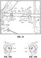
- a method of manufacturing a connection mechanism for a surgical instrumentincludes: assembling first and second jaw members within a clevis disposed at a distal end of an outer drive shaft of a surgical instrument; inserting an end of a pivot pin including a ball-like stop on the opposite end thereof through a hole defined in a first outer wall of the clevis, through pivot bores defined within the first and second jaw members, and through a hole defined in a second outer wall of the clevis to expose a portion of the end of the pivot pin relative to the clevis; and melting the exposed portion of the end of the pivot pin to form a second ball-like stop and secure the first and second jaw members within the clevis.
- a method of manufacturing a connection mechanism for a surgical instrumentincludes: assembling first and second jaw members within a clevis disposed at a distal end of an outer drive shaft of a surgical instrument; inserting a first end of a pivot pin through a hole defined in a first outer wall of the clevis, through pivot bores defined within the first and second jaw members, and through a hole defined in a second outer wall of the clevis to expose a portion of the first end of the pivot pin relative to the clevis and keep exposed a portion of a second end of the pivot pin relative to the clevis; and melting the exposed portions of the first and second ends of the pivot pin to form ball-like stops on both ends of the pivot pin and secure the first and second jaw members within the clevis.
- the pivot pinis made from a super-elastic alloy. In other aspects according to the present disclosure, the pivot pin is made from a material having a different material properties than the clevis such as a non-metallic alloy or a refractory alloy. Still in other aspects according to the present disclosure, a laser is used to melt the exposed portion of the end of the pivot pin.
- a method of manufacturing a connection mechanism for a surgical instrumentincludes: assembling first and second jaw members within a clevis disposed at a distal end of an outer drive shaft of a surgical instrument; inserting a first end of a pivot pin through a hole defined in a first outer wall of the clevis, through pivot bores defined within the first and second jaw members, and through a hole defined in a second outer wall of the clevis to expose a portion of the first end of the pivot pin relative to the clevis while keeping a second end of the pivot pin exposed relative to the second outer wall of the clevis; and melting the exposed portions of the first and second ends of the pivot pin to form stops and secure the first and second jaw members within the clevis.
- the methodfurther includes manufacturing the stop or stops utilizing a laser, a heat-based process, a non-heat based process or mechanically engaging two or more components.
- one or both holes in the outer wall of the clevismay include a geometry complementary to a shape of the second stop to enhance rotation of the pivot pin.
- FIG. 1is a perspective view of an electrosurgical forceps according to an embodiment of the present disclosure including a housing, an elongated shaft, and an end effector;
- FIG. 2Ais an enlarged perspective view of the end effector of FIG. 1 depicted with a pair of jaw members in an open configuration;
- FIG. 2Bis an enlarged perspective view of the end effector of FIG. 1 depicted with the pair of jaw members in a closed configuration;
- FIG. 3Ais a perspective view of the end effector and elongated shaft of FIG. 1 with parts separated;
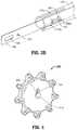
- FIG. 3Bis an enlarged perspective view of a distal portion of the electrosurgical forceps of FIG. 1 depicting a distal knife guide coupled to an inner shaft member;
- FIG. 4is a proximally-facing perspective view of a rotation knob depicting a cavity for receiving the elongated shaft of FIG. 1 ;
- FIG. 5is a cross-sectional, perspective view of the end effector assembled with the elongated shaft of FIG. 1 ;
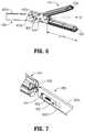
- FIG. 6is a partial, perspective view of a distal portion of a jaw actuation mechanism of the end effector of FIG. 1 ;
- FIG. 7is a partial, perspective view of distal portion of a knife actuation mechanism of the end effector of FIG. 1 ;
- FIG. 8is a perspective view of a lower jaw member of the end effector of FIG. 1 depicting a double flag at a proximal end thereof;
- FIG. 9is a cross-sectional, perspective view of the lower jaw member of FIG. 8 ;
- FIG. 10is a schematic view of the nestled arrangement of the double flag of FIG. 8 with a double flag of an upper jaw member;
- FIG. 11is a schematic view of an alternative offset arrangement of double flags of an alternate pair of jaw members
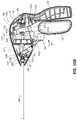
- FIG. 12is a perspective view of a proximal portion of the instrument of FIG. 1 with a portion of the housing removed revealing internal components;
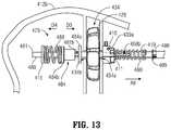
- FIG. 13is a partial, side view of a proximal portion of the jaw actuation mechanism of FIG. 6 depicting a connection between the jaw actuation mechanism and the jaw drive rod mechanism for imparting longitudinal movement to the jaw drive rod;
- FIG. 14Ais a perspective view of a proximal portion of the knife actuation mechanism of the end effector of FIG. 1 ;
- FIG. 14Bis a cross-sectional, top view of a knife collar of the knife actuation mechanism of the end effector of FIG. 1 ;
- FIG. 15Ais a side view of the proximal portion of the instrument of FIG. 12 depicting a movable handle in a separated position with respect to a stationary handle, which corresponds to the open configuration of the end effector depicted in FIG. 2A , and a knife trigger in a separated configuration with respect to the stationary handle, which corresponds to an un-actuated or proximal configuration of a knife with respect to the jaw members;
- FIG. 15Bis a side view of the proximal portion of the instrument of FIG. 12 depicting the movable handle in an intermediate position with respect to the stationary handle, which corresponds to a first closed configuration of the end effector wherein the jaw members encounter one another;
- FIG. 15Cis a side view of the proximal portion of the instrument of FIG. 12 depicting the movable handle in an approximated configuration with respect to the stationary handle, which corresponds to a second closed configuration of the end effector wherein the jaw members apply an appropriate pressure to generate a tissue seal;
- FIG. 15Dis a side view of the proximal portion of the instrument of FIG. 12 depicting the knife trigger in an actuated configuration, which corresponds to an actuated or distal position of the knife with respect to the jaw members;
- FIG. 16is a partial, side view of a proximal portion of an alternate embodiment of a connection mechanism such as the jaw actuation mechanism of FIG. 13 depicting a connection between the jaw actuation mechanism and the jaw drive rod mechanism for imparting longitudinal movement to the jaw drive rod in a manner to enhance the delivery of a required shaft force such as to the jaw members illustrated in FIG. 6 ;
- FIG. 17is a partial, side view of a proximal portion of the jaw actuation mechanism of FIG. 16 depicting, without the movable handle, an alternate embodiment of the connection between the jaw actuation mechanism and the jaw drive rod mechanism for imparting longitudinal movement to the jaw drive rod;
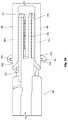
- FIG. 18is a cross-sectional, side view of an inner shaft member illustrating apertures in the inner shaft member and engagement of a drive collar and stop members on the inner shaft member;
- FIG. 19Ais a perspective view of the inner shaft stop member of FIGS. 16-18 ;
- FIG. 19Bis another perspective view of the inner shaft stop member of FIGS. 16-18 ;
- FIG. 20Ais a perspective view of the drive collar stop member of FIGS. 16-18 ;
- FIG. 20Bis another perspective view of the drive collar stop member of FIGS. 16-18 ;
- FIG. 21Ais a perspective detail view of the drive collar of FIGS. 17-18 ;
- FIG. 21Bis another perspective detail view of the drive collar of FIGS. 17-18 ;
- FIG. 22is a perspective view of the apertures in the inner shaft member of FIG. 18 ;
- FIG. 23is a perspective view of the inner shaft member and drive collar and stop members on the inner shaft member
- FIG. 24Ais an exploded view of the inner shaft member and drive collar and stop members with respect to the inner shaft member;
- FIG. 24Bis an alternate exploded view of the inner shaft member and drive collar and stop members with respect to the inner shaft member as illustrated in FIG. 24A which includes directional arrows to illustrate the movement of the drive collar and stop members with respect to the apertures in the inner shaft member;
- FIG. 24Cis another exploded view of the inner shaft member and drive collar and stop members with respect to the inner shaft member;
- FIG. 25is a cutaway view of an electrosurgical forceps that includes the inner shaft member and drive collar and stop members on the inner shaft member of FIGS. 16-24C ;
- FIG. 26is an enlarged view of the end effector showing a pair of opposing ball-like stops formed when one or both ends of the pivot pin are melted to trap the jaw members within a clevis at the end of the outer shaft.
- an embodiment of an electrosurgical forceps 400generally includes a housing 412 that supports various actuators thereon for remotely controlling an end effector 414 through an elongated shaft 416 .
- this configurationis typically associated with instruments for use in laparoscopic or endoscopic surgical procedures, various aspects of the present disclosure may be practiced with traditional open instruments and in connection with endoluminal procedures as well.
- the housing 412is constructed of a left housing half 412 a and a right housing half 412 b .
- the left and right designation of the housing halves 412 a , 412 brefer to the respective directions as perceived by an operator using the forceps 400 .
- the housing halves 412 a , 412 bmay be constructed of sturdy plastic, and may be joined to one another by adhesives, ultrasonic welding or other suitable assembly methods.
- the housing 412supports a stationary handle 420 , a movable handle 422 , a trigger 426 and a rotation knob 428 .
- the movable handle 422is operable to move the end effector 414 between an open configuration ( FIG. 2A ) wherein a pair of opposed jaw members 430 , 432 are disposed in spaced relation relative to one another, and a closed or clamping configuration ( FIG. 2B ) wherein the jaw members 430 , 432 are closer together.
- Approximation of the movable handle 422 with the stationary handle 420serves to move the end effector 414 to the closed configuration and separation of the movable handle 422 from the stationary handle 420 serves to move the end effector 414 to the open configuration.
- the trigger 426is operable to extend and retract a knife blade 456 (see FIGS. 2A and 2B ) through the end effector 414 when the end effector 414 is in the closed configuration.
- the rotation knob 428serves to rotate the elongated shaft 416 and the end effector 414 about a longitudinal axis A-A extending through the forceps.
- the housing 412supports a switch 436 thereon, which is operable by the user to initiate and terminate the delivery of electrosurgical energy to the end effector 414 .
- the switch 436is in electrical communication with a source of electrosurgical energy such as electrosurgical generator 440 or a battery (not shown) supported within the housing 412 .
- the generator 440may include devices such as the LIGASURE® Vessel Sealing Generator and the Force Triad® Generator as sold by Covidien Energy-based Devices of Boulder, Colo.
- a cable 442extends between the housing 412 and the generator 440 and may include a connector (not shown) thereon such that the forceps 400 may be selectively coupled and decoupled electrically from the generator 440 .
- the end effector 414may be moved from the open configuration ( FIG. 2A ) wherein tissue (not shown) is received between the jaw members 430 , 432 , and the closed configuration ( FIG. 2B ), wherein the tissue is clamped and sealed.
- Upper jaw member 430 and lower jaw member 432are mechanically coupled to the elongated shaft 416 about a pivot pin 444 .
- the upper and lower jaw members 430 , 432are electrically coupled to cable 442 , and thus to the generator 440 (e.g., via a respective wire extending through the elongated shaft 416 ) to provide an electrical pathway to a pair of electrically conductive, tissue-engaging sealing plates 448 , 450 disposed on the lower and upper jaw members 432 , 430 , respectively.
- a pair of wire conduits 478 a and 478 bmay be provided to guide wires proximally from the end effector 414 .
- the wire conduits 478 a and 478 bmay be constructed of a plastic tube, and serve to protect wires from sharp edges that may form on surrounding components.
- the sealing plate 448 of the lower jaw member 432opposes the sealing plate 450 of the upper jaw member 430 , and, in some embodiments, the sealing plates 448 and 450 are electrically coupled to opposite terminals, e.g., positive or active (+) and negative or return ( ⁇ ) terminals associated with the generator 440 .
- bipolar energymay be provided through the sealing plates 448 and 450 .
- the sealing plates 448 and 450 and/or the end effector 414may be configured for delivering monopolar energy to the tissue.
- the one or both sealing plates 448 and 450deliver electrosurgical energy from an active terminal, e.g. (+), while a return pad (not shown) is placed generally on a patient and provides a return path to the opposite terminal, e.g. ( ⁇ ), of the generator 440 .
- the jaw members 430 , 432may be pivoted about the pivot pin 444 to move the end effector 414 to the closed configuration of FIG. 2B wherein the sealing plates 448 , 450 provide a pressure to tissue grasped therebetween.
- a pressurewithin a range between about 3 kg/cm 2 to about 16 kg/cm 2 and, desirably, within a working range of 7 kg/cm 2 to 13 kg/cm 2 is applied to the tissue.
- a separation or gap distance “G”may be maintained between the sealing plates 448 , 450 by an array of stop members 454 ( FIG. 2A ) disposed on or adjacent the sealing plates 448 , 450 .
- the stop members 454contact opposing surfaces on the opposing jaw member 430 , 432 and prohibit further approximation of the sealing plates 448 , 450 .
- an appropriate gap distanceof about 0.001 inches to about 0.010 inches and, desirably, between about 0.002 and about 0.005 inches may be provided.
- the stop members 454are constructed of an electrically non-conductive plastic or other material molded onto the jaw members 430 , 432 , e.g., by a process such as overmolding or injection molding.
- the stop members 454are constructed of a heat-resistant ceramic deposited onto the jaw members 430 , 432 .
- Electrosurgical energymay be delivered to the tissue through the electrically conductive seal plates 448 , 450 to effect a tissue seal.
- a knife blade 456may be advanced through a knife channel 458 defined in one or both jaw members 430 , 432 to transect the sealed tissue.
- Knife blade 456is depicted in FIG. 2A as extending from the elongated shaft 416 when the end effector 414 is in an open configuration.
- a knife lockoutis provided to prevent extension of the knife blade 456 into the knife channel 458 when the end effector 414 is in the open configuration, thus preventing accidental or premature transection of tissue and avoiding safety concerns.
- the elongated shaft 416includes various longitudinal components that operatively couple the end effector 414 to the various actuators supported by the housing 412 ( FIG. 1 ).
- An outer shaft member 460defines an exterior surface of the elongated shaft 416 and supports movement of other components therethrough as described below.
- the outer shaft member 460may be constructed from a flat stock piece of metal.
- a stamping, punching or similar metal-working processmay be employed to initially generate a flat blank that includes an appropriate outer profile and any interior openings or features. Thereafter, the necessary bends and curves may be formed by bending the flat blank with a press brake, or other suitable metal-working equipment.
- the outer shaft member 460may be formed by folding the flat blank into a generally circular profile (or generally rectangular profile) such that two opposing longitudinal edges of the flat blank meet at a longitudinal seam (not explicitly shown).
- a longitudinal seamdoes not necessarily require joining by a mechanical interlock or any other suitable process, the seam may, in some embodiments, be joined by laser welding (or other suitable process) to form a continuous circular or other geometric (e.g., rectangular) profile.
- the seammay be generally straight, or alternatively, a box joint, a dovetail joint, or any other suitable interface known in the metal-working arts.
- the outer shaft member 460defines a clevis 464 at a distal end thereof for receiving the jaw members 430 and 432 .
- Opposing vertical sidewalls 464 a and 464 b of the outer shaft member 460include respective bores 466 a , 466 b extending therethrough to frictionally support the pivot pin 444 and maintain an orientation of the pivot pin 444 with respect to the outer shaft member 460 .
- the pivot pin 444may be fastened to the outer shaft member 460 by a laser or heat-based welding, adhesives, chemical bonding, or other suitable manufacturing processes.
- the proximal portion of the outer shaft member 460includes, in order from distal to proximal, a series of tabs 486 extending therefrom, a washer 499 extending around outer shaft member 460 , a pair of opposing longitudinal slots 468 a , 468 b defined therethrough and provided to allow longitudinal translation of a dowel pin 493 therethrough, and a longitudinal slot 469 extending distally from a proximal end thereof to couple the outer shaft member 460 to the rotation knob 428 .
- connection established between the outer shaft member 460 and the rotation knob 428is described below with reference to FIG. 4 .
- the series of tabs 486 and the washer 499serve to aid in securing the proximal portion of the outer shaft member 460 within the housing 412 .
- the pivot pin 444extends through a proximal portion of each of the jaw members 430 , 432 to pivotally support the jaw members 430 , 432 at the distal end of the outer shaft member 460 .
- a proximal portion of each of the jaw members 430 , 432is configured as a “double flag.”
- the double flag configurationrefers to the two laterally spaced parallel flanges or “flags” 430 a , 430 b and 432 a , 432 b respectively, extending proximally from a distal portion of the jaw members 430 and 432 .
- a lateral cam slot 430 c and a lateral pivot bore 430 dextend through each of the flags 430 a , 430 b of the upper jaw member 430 .
- a lateral cam slot 432 c and a lateral pivot bore 432 dextend through each of the flags 432 a , 432 b of the lower jaw member 432 .
- the pivot bores 430 d , 432 dreceive the pivot pin 444 in a slip-fit relation that permits the jaw members 430 , 432 to pivot about the pivot pin 444 to move the end effector 414 between the open and closed configurations ( FIGS. 2A and 2B , respectively).
- An inner shaft member 480is received within the outer shaft member 460 and is configured for longitudinal motion with respect to the outer shaft member 460 .
- a distal knife guide 486includes sidewalls 482 a , 482 b and a proximal key slot 487 that supports a key member 494 therethrough.
- the distal knife guide 486is slid proximally within a distal end of the inner shaft member 480 , such that the inner shaft member 480 surrounds a portion of the distal knife guide 486 , and opposing lateral sides of the key member 494 align with and fit within opposing longitudinal key slots 495 a , 495 b defined through the inner shaft member 480 to couple the knife guide 486 to the inner shaft member 480 ( FIG. 3B ).
- the inner shaft member 480includes a pair of opposing longitudinal slots 472 a , 472 b extending proximally from a distal end of the inner shaft member 480 along a portion of the inner shaft member 480 between the opposing longitudinal key slots 495 a , 495 b .
- the longitudinal slots 472 a , 472 ballow the distal end of the inner shaft member 480 to aid in sliding of the distal knife guide 486 proximally within the inner shaft member 480 .
- the sidewalls 482 a , 482 bdefine a longitudinal slot 483 through the distal knife guide 486 that provides lateral support to the knife 402 .
- the knife 402is substantially surrounded at a distal end thereof by the distal knife guide 486 on four lateral sides and the sidewalls 482 a , 482 b of the distal knife guide 486 constrain side-to-side lateral motion of the knife 402 .
- the distal knife guide 486serves to urge the knife 402 into a central position within the elongated shaft 416 , thereby ensuring proper alignment of the knife 402 as the knife 402 reciprocates within knife channel 458 ( FIG. 2A ).
- the distal knife guide 486includes features for operatively coupling the inner shaft member 480 to the end effector 414 .
- a proximal portion 488 of the inner shaft member 480is configured for receipt within the housing 412 ( FIG. 1 ), and includes features for operatively coupling the inner shaft member 480 to the actuators supported thereon, e.g. the movable handle 422 .
- the distal knife guide 486includes a through bore 490 extending through the sidewalls 482 a , 482 b for receiving the cam pin 492 .
- a longitudinal slot 496is defined through the sidewalls 482 a , 482 b .
- the longitudinal slot 496provides clearance for the pivot pin 444 , and thus, permits longitudinal reciprocation of the inner shaft member 480 independent of the pivot pin 444 .
- the proximal portion 488 of the inner shaft member 480includes, in order from distal to proximal, a pair of opposing longitudinal knife slots 488 a , 488 b extending therethrough, a pair of opposing distal locking slots 481 a , 481 b extending therethrough, a pair of opposing proximal locking slots 471 a , 471 b extending therethrough, and a proximal end 491 configured to engage a suitable mechanical interface within the housing 412 to aid in proper support of the inner shaft member 480 within the housing 412 (see FIGS. 12 and 15A-15D ).
- the knife 402is a generally flat, metal component defining a profile that may be constructed by a stamping process.
- the knife 402supports the sharpened knife blade 456 at a distal-most end thereof.
- the sharp edge of the knife blade 456may be applied to the distal end of the knife 402 subsequent to the stamping process that forms the profile.
- various manufacturing techniquesmay be employed such as grinding, coining, electrochemical etching, electropolishing, or other suitable manufacturing processes, for forming sharpened edges.
- a longitudinal slot 406is defined within the knife 402 to provide clearance for the pivot pin 444 , the cam pin 492 , and the key member 494 .
- a proximal through bore 408 aextends through a proximal portion 408 of the knife 402 and provides a mechanism for operatively coupling the knife 402 to the trigger 426 via the dowel pin 493 .
- the connection between the knife 402 and the trigger 426is described in detail below with reference to FIGS. 12, 13, 14A, and 14B .
- the rotation knob 428includes a passageway 429 defined therethrough for receiving the outer shaft member 460 .
- the passageway 429has a generally circular profile corresponding to the circular profile of the outer shaft member 460 .
- the passageway 429includes a longitudinal keying member 414 that is configured to align with and be seated within longitudinal slot 469 ( FIG. 3A ) of the outer shaft member 460 .
- the keying member 414projects laterally inward along the length of passageway 429 such that the insertion of the proximal end of the outer shaft member 460 into the passageway 429 of the rotation knob 428 operatively couples the outer shaft member 460 to the rotation knob 428 and, thus, permits longitudinal motion of the inner shaft member 480 therethrough.
- a cable clearance passageway(not shown) is defined through rotation knob 428 to permit passage of electrical cables or wires that electrically couple the sealing plates 448 , 450 to the electrosurgical generator 440 ( FIG. 1 ). Rotational motion imparted to the rotation knob 428 may thus impart rotational motion to each of the components of the elongated shaft 416 , and to the end effector 414 , which is coupled thereto.
- the rotation knob 428is seated within an interior compartment 434 of the housing 412 and, as shown in FIG. 1 , extends laterally outward from opposing sides of the housing 412 (only shown extending laterally outward from housing half 412 b ).
- the interior compartment 434defines distal and proximal passageways 434 a and 434 b that permit the passage of the components of the elongated shaft 416 therethrough.
- the rotational motion of the rotation knob 428may be limited by a stop boss 430 projecting distally from the rotation knob 428 ( FIG. 4 ).
- the stop boss 430is positioned to engage the distal passage 434 a of the compartment 434 to restrict rotational motion of the rotation knob 428 .
- the stop boss 430may engage the distal passage 434 a to restrict rotational motion of the rotation knob 428 to 180 degrees in either direction.
- the end effector 414is coupled to the distal end of the elongated shaft 416 by the pivot pin 444 .
- the pivot pin 444is coupled to the sidewalls 464 a and 464 b of the clevis 464 defined at the distal end of the outer shaft member 460 .
- the pivot pin 444represents a longitudinally stationary reference for the longitudinal movements of inner shaft member 480 and the knife 402 .
- the pivot pin 444extends through the flags 432 a , 432 b of the lower jaw member 432 , the flags 430 a and 430 b of the upper jaw member 430 , the sidewalls 482 a , 482 b of the knife guide 486 , and the knife 402 .
- the jaw members 430 , 432are free to pivot about the pivot pin 444 , and the inner shaft member 480 and the knife 402 are free to translate longitudinally around the pivot pin 444 .
- the end effector 414is shown in the open configuration. Since the knife guide 486 is coupled to the cam pin 492 , when the inner shaft member 480 is in the distal position, the cam pin 492 is located in a distal position in cam slots 430 c and 432 c defined through the flags 430 a , 430 b , 432 a , 432 b of the jaw members 430 , 432 , respectively.
- the inner shaft member 480may be drawn proximally relative to the pivot pin 444 to move the end effector 414 to the closed configuration (see FIG. 2B ). Since the longitudinal position of the pivot pin 444 is fixed (by the outer shaft member 460 , which is removed from view in FIG. 6 for clarity), and since the cam slots 430 c , 432 c are obliquely arranged with respect to the longitudinal axis A-A, proximal retraction of the cam pin 492 through the cam slots 430 c , 432 c induces the jaw members 430 , 432 to pivot toward one another about the pivot pin 444 . Conversely, when the end effector 414 is in the closed configuration, longitudinal translation of the inner shaft member 480 in a distal direction induces the jaw members 430 , 432 to pivot away from one another toward the open configuration.
- the longitudinal slot 406 in the knife 402extends around both the pivot pin 444 and the cam pin 492 , and thus the pins 444 , 492 do not interfere with the reciprocal motion of the knife 402 .
- the pivot pin 444 and cam pin 492extend through the slot 406 in such a manner as to guide longitudinal motion of the knife 402 as well as constrain vertical motion of the knife 402 .
- the blade 456 at the distal-most end of the knife 402is centrally aligned by the knife guide 486 , as discussed hereinabove. Properly aligned, the blade 456 readily enters the knife channel 458 defined in the jaw members 430 , 432 .
- the lower jaw member 432is constructed of three major components. These components include a double-flag jaw insert 440 , an insulator 442 and the sealing plate 448 .
- the flags 432 a , 432 b of the jaw member 432define a proximal portion of the double-flag jaw insert 440 , and a generally u-shaped channel 444 extends distally to support the tissue engaging portion of the jaw member 432 .
- the double-flag jaw insert 440includes various planar surfaces, and may be constructed as a sheet metal component formed by a stamping process.
- the cam slots 432 c and pivot holes 432 dmay be punched into a flat blank, and subsequently the blank may be bent to form the flags 432 a , 432 b and the u-shaped channel 444 .
- the insulator 442may be constructed of an electrically insulative plastic such as a polyphthalamide (PPA) (e.g., Amodel®), polycarbonate (PC), acrylonitrile butadiene styrene (ABS), a blend of PC and ABS, nylon, ceramic, etc.
- PPApolyphthalamide
- PCpolycarbonate
- ABSacrylonitrile butadiene styrene
- the electrically insulative plasticmay be overmolded onto the jaw insert 440 in a single-shot injection molding process such that sealing plate 448 is overmolded to the jaw insert 440 .
- the electrically insulative plasticmay be mechanically coupled to the jaw insert 440 , e.g., pressed, snapped, glued, etc.
- Various featuresmay be molded into the insulator 442 that facilitate the attachment of the sealing plate 448 to the insert 440 .
- tabsmay be provided that permit a snap-fit attachment of the sealing plate 448 , or ridges may formed that permit ultrasonic welding of the sealing plate 448 onto the insulator 442 .
- the sealing plate 448may be constructed of an electrically conductive metal, and may be stamped from a flat sheet stock.
- the flags 430 a , 430 b of the upper jaw member 430are depicted schematically in a nestled configuration with respect to the flags 432 a , 432 b of the lower jaw member 432 .
- the proximal portion of the upper jaw member 430is narrower than the proximal portion of the lower jaw member 432 , and thus, a lateral spacing “S” between the flags 432 a , 432 b is sufficient to permit the flags 430 a and 430 b to be positioned therebetween.
- a pivot axis “P 0 ”extends through an overlapping portion of the flags 430 a , 432 a , and 430 b , 432 a such that the upper and lower jaw members 430 , 432 may pivot about the common axis “P 0 .”
- the proximal portions of the upper and lower jaw members 430 , 432also share a common centerline “CL-1” that is transverse with respect to the pivot axis “P 0 .”
- a proximal portion of double-flag upper jaw member 450includes flags 450 a and 450 b .
- a proximal portion of a double-flag lower jaw member 452includes flags 452 a and 452 b and exhibits a width that is identical to a width of the proximal portion of the upper jaw member 450 .
- one flag 450 a of the upper jaw member 450is positioned on a laterally exterior side of the corresponding flag 452 a of the lower jaw member 452
- the other flag 450 b of the upper jaw member 450is positioned on a laterally interior side of the corresponding flag 452 b of the lower jaw member 452 .
- a centerline “CL-2” of the proximal portion of the upper jaw member 450is laterally offset with respect to a centerline “CL-3” of the lower jaw member 452 .
- the movable handle 422may be manipulated to impart longitudinal motion to the inner shaft member 480
- the knife trigger 426may be manipulated to impart longitudinal motion to the knife 402 .
- longitudinal motion of the inner shaft member 480serves to move the end effector 414 between the open configuration of FIG. 2A and the closed configuration of FIG. 2B
- longitudinal motion of the knife 402serves to move knife blade 456 through knife channel 458 ( FIG. 2A ).
- the movable handle 422is operatively coupled to the inner shaft member 480 by a connection mechanism 476 ( FIG. 12 ).
- the connection mechanism 476includes a clevis 478 defined at an upper end of the movable handle 422 .
- the clevis 478is pivotally supported on the left housing half 412 b by a pivot boss 479 .
- a second complementary pivot boss(not shown) is provided on the right housing half 412 a to support the clevis 478 .
- Each of two upper flanges 478 a and 478 b of the clevis 478extend upwardly about opposing sides of a drive collar 484 supported on the inner shaft member 480 and include rounded drive surfaces 497 a and 497 b thereon.
- Drive surface 497 aengages a proximal-facing surface of a distal lock collar 484 a and drive surface 497 b engages a distal facing surface of a proximal rim 484 b of the drive collar 484 ( FIG. 13 ).
- the distal lock collar 484 aengages the opposing distal locking slots 481 a , 481 b ( FIG. 3A ) extending through the proximal portion 488 of the inner shaft member 480 to lock-fit the distal lock collar 484 a to the inner shaft member 480 .
- the distal lock collar 484 ais prevented from longitudinal motion relative to the inner shaft member 480 .
- Drive surface 497 ais arranged along the longitudinal axis A-A such that pivotal motions of the movable handle 422 about the pivot bosses 479 induce corresponding longitudinal motion of the drive collar 484 along the longitudinal axis A-A in the proximal direction.
- Drive surface 497 bis arranged along the longitudinal axis A-A such that pivotal motions of the movable handle 422 about the pivot bosses 479 induce corresponding longitudinal motion of the distal lock collar 484 a along the longitudinal axis A-A in the distal direction.
- proximal longitudinal motionmay be imparted to the inner shaft member 480 by pushing the proximal rim 484 b of the drive collar 484 proximally with the movable handle 422 ( FIG. 12 ) as indicated by arrow D 4 .
- the proximal rim 484 bengages a spring 489 that is constrained between the proximal rim 484 b and a proximal lock collar 415 .
- the proximal lock collar 415engages the opposing proximal locking slots 471 a , 471 b ( FIG.
- proximal lock collar 415is prevented from longitudinal motion relative to the inner shaft member 480 and serves as a proximal stop against which spring 489 compresses.
- Distal longitudinal motionis imparted to the inner shaft member 480 by pushing the distal lock collar 484 a distally with drive surface 497 a of movable handle 422 as indicated by arrow D 3 ( FIG. 13 ).
- Distal longitudinal motion of the distal lock collar 484 ainduces a corresponding distal motion of the inner shaft member 480 by virtue of the lock-fit coupling of the distal lock collar 484 a to the opposing proximal locking slots 471 a , 471 b extending through the proximal portion 488 of the inner shaft member 480 ( FIG. 3A ).
- Proximal longitudinal motion of the inner shaft member 480draws the cam pin 492 proximally to pivot the jaw members 430 , 432 toward one another to move the end effector 414 to the closed configuration as described above with reference to FIG. 6 .
- the inner shaft member 480essentially bottoms out (i.e., further proximal movement of the inner shaft member 480 is prohibited since the jaw members 430 , 432 contact one another). Further proximal movement of the movable handle 422 (FIG. 12 ), however, will continue to move the drive collar 484 proximally.
- the spring 489also serves to bias the movable handle 422 to an open configuration such that the movable handle 422 is separated from the stationary handle 420 .
- the trigger 426is pivotally supported in the housing 412 about a pivot boss 403 protruding from the trigger 426 .
- the trigger 426is operatively coupled to the knife 402 by a knife connection mechanism 404 such that pivotal motion of the trigger 426 induces longitudinal motion of the knife 402 .
- the knife connection mechanism 404includes upper flanges 426 a , 426 b of the trigger 426 and a knife collar 410 .
- the knife collar 410includes a cap member 411 coupled thereto and a pair of integrally formed pin bosses 439 a , 439 b extending from opposing sides thereof.
- the knife collar 410may include indentations or catches defined therein (not shown) that receive corresponding snap-in features (e.g., arms) of the cap member 411 .
- the cap 411may thus be assembled to the knife collar 410 such that the cap 411 and the knife collar 410 translate together. As shown by FIG.
- the coupling of the knife collar 410 to the cap 411forms an interior circular channel 413 to capture the dowel pin 493 therein such that the dowel pin 493 is supported on opposing ends between the knife collar 410 and the cap 411 .
- the dowel pin 493extends through the proximal through bore 408 a extending through a proximal portion 408 of the knife 402 ( FIG. 3A ) to operably couple the knife 402 to the knife collar 410 .
- dowel pin 493translates longitudinally within knife slots 488 a , 488 b , respectively, of the inner shaft member 480 such that the longitudinal motion of inner shaft member 480 is unimpeded by dowel pin 493 .
- dowel pin 493freely rotates within the interior circular channel 413 such that the outer and inner shaft members 460 and 480 (removed from view in FIG. 14B for clarity), the knife 402 , and the dowel pin 493 rotate within the knife collar 410 about the longitudinal axis A-A.
- the knife collar 410serves as a stationary reference for the rotational movement of the outer shaft member 460 , the inner shaft member 480 , the knife 402 , and the dowel pin 493 .
- the upper flanges 426 a , 426 b of the trigger 426include respective slots 427 a , 427 b defined therethrough that are configured to receive the pin bosses 439 a , 439 b , respectively, of the knife collar 410 such that pivotal motion of the trigger 426 induces longitudinal motion of the knife collar 410 and, thus, the knife 402 by virtue of the coupling of knife 402 to the knife collar 410 via the dowel pin 493 extending through the through bore 408 a .
- dowel pin 493translates longitudinally within the opposing slots 468 a , 468 b of the outer shaft member 460 and the slots 488 a , 488 b of the inner shaft member 480 .
- the knife collar 410when the trigger 426 is moved to induce motion of the knife collar 410 in order to translate the blade 456 through the knife channel 458 , the knife collar 410 translates along the outer shaft member 460 in the direction of arrow A 9 to abut a spring 419 such that spring 419 compresses against a distal portion 421 of the interior of the housing 412 ( FIG. 12 ).
- the spring 419biases the knife collar 410 in a proximal direction to a proximal position along the outer shaft member 460 .
- a sequence of motionsmay be initiated by moving the movable handle 422 to induce motion of the jaw drive mechanism in order to close the jaws 430 , 432 , and by moving the trigger 426 to induce motion of the knife collar 410 in order to translate the blade 456 through the knife channel 458 .
- both the moveable handle 422 and the knife trigger 426are in a distal or un-actuated position as depicted in FIG. 15A .
- This arrangement of the moveable handle 422 and trigger 426sustains the end effector 414 in the open configuration ( FIG.
- the movable handle 422may be moved from the distal position of FIG. 15A to the intermediate position depicted in FIG. 15B to move the jaw members 430 , 432 to the closed configuration ( FIG. 2B ).
- the drive surface 497 b of the movable handle 422engages the proximal rim 484 b of the drive collar 484 .
- the drive collar 484 and the spring 489are both driven proximally against the proximal lock collar 415 and, thus, the inner shaft member 480 is driven proximally in the direction of arrow M 2 ( FIG. 15B ).
- proximal movement of the inner shaft member 480serves to draw the cam pin 492 proximally though the cam slots 430 c , 432 c of the jaw members 430 , 432 , respectively, and thus pivot the jaw members 430 , 432 toward one another.
- the jaw actuation mechanism“bottoms out” and further proximal movement of the cam pin 492 and the inner shaft member 480 is prevented.
- the movable handle 422may be moved from the intermediate position of FIG. 15B to the actuated or proximal position of FIG. 15C to increase the pressure applied by the jaw members 430 , 432 .
- the drive surface 497 bpresses the proximal rim 484 b of the drive collar 484 further distally against the spring 489 in the direction of arrow M 4 ( FIG. 15C ).
- the spring 489is compressed against the proximal lock collar 415 , and a tensile force is transmitted through the inner shaft member 480 to the jaw members 430 , 432 .
- the tensile force supplied by the spring 489ensures that the jaw members 430 , 432 apply an appropriate pressure to effect a tissue seal.
- electrosurgical energymay be selectively supplied to the end effector 414 to generate a tissue seal.
- a t-shaped latch 422 aextending proximally from an upper portion of the moveable handle 422 is received in a railway 420 a supported within the stationary handle 420 .
- the railway 420 aserves to temporarily lock the movable handle 422 in the proximal position against the bias of the spring 489 .
- the railway 420 apermits the maintenance of pressure at the end effector 414 without actively maintaining pressure on the movable handle 422 .
- the flange 422 amay be released from the railway 420 a by pivoting the movable handle 422 proximally and releasing the movable handle 422 to move under the influence of the spring 489 .
- the knife trigger 426When the movable handle 422 is in the actuated or proximal position, the knife trigger 426 may be selectively moved from the distal position of FIG. 15C to the proximal position of FIG. 15D to advance the knife blade 456 distally through knife channel 458 .
- the knife trigger 426may be pivoted in the direction of arrow M 5 ( FIG. 15D ), about pivot boss 403 to advance the flange 426 b of the knife trigger 426 distally in the direction of arrow M 6 such that the pin boss 439 b translates within slot 427 b from the position shown in FIGS. 15A-15C to the position shown in FIG. 15D .
- pin boss 439 atranslates within slot 427 a in the same manner as described above with respect to pin boss 439 b and slot 427 b .
- Movement of flanges 426 a , 426 bdraws the knife collar 410 distally, which induces distal longitudinal motion of the knife 402 by virtue of the coupling of knife 402 to the knife collar 410 via the dowel pin 493 extending through the through bore 408 a , as described above with reference to FIGS. 3A and 14B .
- connection mechanism for a surgical instrumente.g., an alternate embodiment of an actuation mechanism such as the connection mechanism 476 described above with respect to FIGS. 12-15D is now described with respect to FIGS. 16-25 .
- like component numberingis utilized to identify like components.
- connection mechanism for a surgical instrumentthat includes an end effector assembly with jaw members such as surgical instrument 400 described above with respect to FIGS. 1-15D
- connection mechanism described hereinmay also be applied to other types of surgical instrumentation.
- FIG. 16is a view of a proximal portion of an alternate embodiment of a connection mechanism for a surgical instrument (e.g., for surgical instrument 400 and elongated shaft member 416 described above with respect to FIGS. 1-15D ) such as the jaw actuation mechanism of FIG. 13 .
- FIG. 16depicts connection mechanism 4760 between the jaw actuation mechanism and the jaw drive rod mechanism for imparting longitudinal movement to the jaw drive rod in a manner to enhance the delivery of a required shaft force such as to the pair of opposed jaw members 430 , 432 illustrated in FIG. 6 via the elongated shaft 416 illustrated, for example, in FIGS. 1, 2A and 2B .
- connection mechanism 4760includes an inner shaft member 4800 that is configured to extend at least partially through an elongated shaft member such as elongated shaft member 416 of surgical instrument 400 .
- Inner shaft member 4800defines proximal end 4910 and a distal end (not explicitly shown but located in the direction of arrow 4912 in FIG. 22 and similarly to slots 472 a and 472 b in inner shaft 480 in FIG. 3A ).
- connection mechanism 4760also includes a drive collar member 4840 , a drive collar stop member 4841 and an inner shaft stop member 4150 .
- inner shaft member 4800includes at least one aperture, e.g., at least distal locking slot 4811 or additionally, as shown, at least distal locking slot 4812 , that is defined in the inner shaft member 4800 .
- the distal locking slots 4811 , 4812extend partially along the longitudinal direction (axis “A”-“A”) of the inner shaft member 4800 and are disposed distally from the proximal end 4910 .
- the inner shaft member 4800is configured such that the inner shaft member 4800 enables drive collar member 4840 to be disposed to slide on the inner shaft member 4800 and movable along the longitudinal direction (axis “A”-“A”) of the inner shaft member 4800 .
- the drive collar member 4840is reciprocally movable along the longitudinal direction (axis “A”-“A”) of the inner shaft member 4800 .
- the distal locking slots 4811 , 4812may be configured in an L-shape, or as shown in FIGS. 18, 22, 24A, 24B and 24C in a T-shape having proximal sections 4811 a , 4812 a and distal sections 4811 b , 4812 b configured such that the open area of the proximal sections 4811 a , 4812 a is greater than the open area of the distal sections 4811 b , 4812 b .
- Such a configuration of the locking slots 4811 , 4812enables a drive collar stop member 4841 to be disposed to slide on the inner shaft member 4800 such that the drive collar stop member 4841 moves first distally in a direction along the longitudinal axis “A”-“A” defined by the inner shaft member 4800 to approach the distal locking slots 4811 , 4812 (see arrow E 1 in FIG. 24B ).
- the drive collar stop member 4841moves in a direction relative to the longitudinal direction defined by axis “A”-“A” by shifting or dropping into engagement (see arrow E 2 in FIG.
- the drive collar stop member 4841is reciprocally movable or slidable along the longitudinal axis “A”-“A” defined by the inner shaft member 4800 .
- the inner shaft member 4800having, for example, a circular cross-sectional configuration with a diameter D, therefore defines a first cross-sectional area B 1 .
- the drive collar stop member 4841defines a central aperture 4842 having a second cross-sectional area B 2 .
- the second cross-sectional area B 2exceeds the first cross-sectional area B 1 of the inner shaft member 4800 so as to define an upper portion 4842 ′ of the second cross-sectional area B 2 and a lower portion 4842 ′′ of the second cross-sectional area B 2 .
- the reduced area of the first cross-sectional area B 1results from the fact that, within the upper portion 4842 ′, the drive collar stop member 4841 defines at least one projection, e.g., as illustrated two projections 4843 ′, 4843 ′′, that project inwardly to reduce the upper portion 4842 ′ of the second cross-sectional area B 2 as compared to the lower portion 4842 ′′.
- the drive collar stop member 4841retains the inner shaft member 4800 in the lower portion 4842 ′′ of the second cross-sectional area B 2 as the drive collar stop member 4841 moves distally along the longitudinal direction between the proximal end 4910 of the inner shaft member 4800 and the distal locking slots 4811 , 4812 .
- the drive collar stop member 4841moves distally along the longitudinal direction (see FIG. 24B , arrow E 1 ) to the distal locking slots 4811 , 4812 .
- the drive collar stop member 4841drops or shifts (see FIG. 24B , arrow E 2 ) to a position wherein the projections 4843 ′, 4843 ′′ engage first with the proximal sections 4811 a , 4812 a and then with the distal sections 4811 b , 4812 b (see FIG. 24B , arrow E 3 ).
- drive collar stop member 4841limits further longitudinal motion of the drive collar member 4840 in the direction of the proximal end 4912 of the inner shaft member 4800 .
- the drive collar stop member 4841defines at least one portion 4841 ′ having a weight density differing from at least another portion 4841 ′′ having another weight density.
- the shift of the drive collar stop member 4841is effected by the difference in weight densities. More particularly, in the exemplary embodiment described herein, portion 4841 ′ defines an upper portion of the drive collar stop member 4841 and portion 4841 ′′ defines a lower portion of the drive collar stop member 4841 .
- the upper portion 4841 ′defines, for example, three apertures 4845 a , 4845 b and 4845 c that are disposed, respectively, as arcuate segments forming a generally concentric configuration around the central aperture 4842 .
- the lower portion 4841 ′′is a solid member such that the weight density exceeds the weight density of the upper portion 4841 ′ that defines the apertures 4845 a , 4845 b , 4845 c .
- the difference in weight densitieseffects the movement or shifting of the drive collar member 4841 in a direction relative to the longitudinal axis “A”-“A” defined by the inner shaft member 4800 (see FIG.
- drive collar member 4840may be configured as a cylindrical member 4844 defining a central aperture 4844 ′ having a diameter D′ that is greater than diameter D of inner shaft member 4800 (see FIG. 23 ) so as to enable the drive collar 4840 to be mounted on the inner shaft member 4800 and reciprocally slide and move along the inner shaft member 4800 .
- FIGS. 18, 22, 24A, 24B and 24Cbest illustrate the inner shaft member 4800 includes at least one additional aperture, e.g., at least proximal locking slot 4711 , or additionally at least proximal locking slot 4712 as shown, that is defined in the inner shaft member 4800 .
- the proximal locking slots 4711 , 4712extend partially along the longitudinal direction (axis “A”-“A”) of the inner shaft member 4800 and may be disposed proximally from the one or more apertures, e.g., distal locking slots 4811 , 4812 , that are disposed distally from the proximal end 4910 .
- the one or more proximal locking slots 4711 , 4712are configured to enable inner shaft stop member 4150 to be disposed to slide on the inner shaft member 4800 and to be movable along the longitudinal direction (axis “A”-“A”) of the inner shaft member 4800 .
- Inner shaft stop member 4150is disposed proximally of the drive collar member 4840 and on the inner shaft member 4800 .
- the one or more proximal locking slots 4711 , 4712are also disposed proximally of the drive collar member 4840 .
- the one or more proximal locking slots 4711 , 4712are configured to enable the inner shaft stop member 4150 to engage in the proximal locking slots 4711 , 4712 and to limit movement of the inner shaft member 4800 along the longitudinal axis “A”-“A” following insertion of spring member 489 on the inner shaft member 4800 between the drive collar member 4840 and the inner shaft stop member 4150 .
- the spring member 489defines a proximal end 4891 and a distal end 4892 .
- the one or more proximal locking slots 4711 , 4712may be configured in an L-shape, or as shown in FIGS. 18, 22, 24A, 24B and 24C in a T-shape having proximal sections 4711 a , 4712 a and distal sections 4711 b , 4712 b configured such that the open area of the proximal sections 4711 a , 4712 a is less than the open area of the distal sections 4711 b , 4712 b.
- such a configuration of the locking slots 4711 , 4712enables the inner shaft stop member 4150 to limit further axial movement of the inner shaft member 4800 . More particularly, the inner shaft stop member 4150 is disposed to slide on the inner shaft member 4800 first in a direction relative to the longitudinal axis “A”-“A” defined by the inner shaft member 4800 (see FIG. 24B , arrow F 1 ) to become engaged first with the one or more distal portions 4711 b , 4712 b .
- the inner shaft stop member 4150then moves proximally in a direction along the longitudinal axis “A”-“A” defined by the inner shaft member 4800 (see FIG. 24B , arrow F 2 ) to engage the one or more proximal portions 4711 a , 4712 a of the proximal locking slots 4711 , 4712 following insertion of the spring member 489 , in a compressed configuration, on the inner shaft member 4800 between the drive collar member 4840 and the inner shaft stop member 4150 . Extension of the spring member 489 pushes inner shaft stop member 4150 proximally into the proximal portions 4711 a , 4712 a to limit movement of the inner shaft member 4800 along the longitudinal axis “A”-“A”.
- the direction relative to the longitudinal axis “A”-“A”includes a direction transverse to or crossing the longitudinal axis “A”-“A”, such as vertically downward as shown by arrow F 1 in FIG. 24B .
- the inner shaft stop member 4150may engage the one or more proximal locking slots 4711 , 4712 via an aperture 4152 defined by the inner shaft stop member 4150 to impart a generally U-shaped configuration to the inner shaft stop member 4150 .
- At least one projectione.g., projections 4154 ′ and 4154 ′′ that are disposed on opposing inner surfaces 4156 ′, 4156 ′′, project inwardly within aperture 4152 and effect the engagement of the inner shaft stop member 4150 with the one or more proximal portions 4711 a , 4712 a of the proximal locking slots 4711 , 4712 , respectively, to limit further proximal axial movement of the inner shaft stop member 4150 .
- the inner shaft stop member 4150is reciprocally movable along the longitudinal axis “A”-“A” of the inner shaft member 4800 .
- the drive collar member 4840may include a proximal rim 4846 that extends concentrically around, and projects radially from, outer diameter D′′ of the cylindrical member 4844 of drive collar member 4840 .
- the drive collar member 4840may further include a projection 4848 that extends proximally from the drive collar member 4840 and which is configured to engage in an aperture 4892 ′ defined in the distal end 4892 of the spring member 489 when the spring member 489 is inserted on the inner shaft member 4800 between the drive collar member 4840 and the inner shaft stop member 4150 (see FIG. 17 ).
- the inner shaft stop member 4150may further include a projection 4158 that extends distally from the inner shaft stop member 4150 and is configured to engage in an aperture 4891 ′ defined in the proximal end 4891 of the spring member 489 when the spring member 489 is inserted on the inner shaft member 4800 between the drive collar member 4840 and the inner shaft stop member 4841 .
- connection mechanism 4760yields a simplified spring load mechanism for delivering shaft load of a surgical instrument.
- the methodincludes moving the drive collar stop member 4841 longitudinally along inner shaft member 4800 (e.g., in the direction of axis “A”-“A”), engaging the drive collar stop member 4841 in at least one aperture defined in the inner shaft member 4800 , e.g., distal locking slot 4811 or additionally at least distal locking slot 4812 , to limit further longitudinal movement of the drive collar stop member 4841 , and moving drive collar member 4840 longitudinally along the inner shaft member 4800 until the drive collar stop member 4840 limits further longitudinal movement of the drive collar member 4840 .
- the methodmay include moving the drive collar stop member 4841 in the direction relative to the longitudinal axis “A”-“A” so as to engage by shifting or dropping, e.g., see FIG. 24B , arrow E 2 , into one or both of the distal locking slots 4811 , 4812 to limit further longitudinal movement of the drive collar stop member 4841 .
- the methodmay include retaining the inner shaft member 4800 in the lower portion 4842 ′′ of the aperture 4842 defined in the drive collar stop member 4841 as the drive collar stop member 4841 moves distally along the longitudinal direction “A”-“A” of the inner shaft member 4800 .
- the methodmay include limiting further longitudinal motion of the drive collar member 4840 in the direction of the proximal end 4912 of the inner shaft member 4800 by engaging the drive collar stop member 4841 with the one or more apertures such as distal locking slots 4811 , 4812 .
- This engagingmay be effected by shifting the drive collar stop member 4841 in a direction relative to the longitudinal movement of the drive collar stop member 4841 , e.g., by shifting or dropping into engagement (see FIG. 24B , arrow E 2 ) first with the proximal sections 4811 a , 4812 a and then with the distal sections 4811 b , 4812 b (see FIG. 24B arrow E 3 ) to limit further longitudinal motion of the drive collar member 4840 in the direction of the proximal end 4912 of the inner shaft member 4800 .
- the drive collar stop member 4841defines at least one portion having a weight density differing from at least another portion having another weight density, e.g., as explained above defining at least one portion 4841 ′ having a weight density differing from at least another portion 4841 ′′ having another weight density.
- the methodmay include shifting of the drive collar stop member 4841 being effected by the difference in weight densities.
- the methodincludes disposing the three apertures 4845 a , 4845 b and 4845 c defined by the upper portion 4841 ′, respectively, as arcuate segments forming a generally concentric configuration around the central aperture 4842 .
- the methodincludes configuring the lower portion 4841 ′′ as a solid member such that the weight density exceeds the weight density of the upper portion 4841 ′ that defines the apertures 4845 a , 4845 b , 4845 c .
- the methodincludes effecting the movement or shifting of the drive collar member 4841 in a direction relative to the longitudinal axis “A”-“A” defined by the inner shaft member 4800 (see FIG.
- the methodmay include inserting spring member 489 in a compressed configuration on the inner shaft member 4800 and moving the spring member 489 longitudinally along the inner shaft member 4800 to contact the drive collar member 4840 to limit further longitudinal movement of the spring member 489 .
- the methodmay include moving inner shaft stop member 4150 in the direction relative to the longitudinal movement of the drive collar stop member 4841 along the inner shaft member (see FIG. 24B , arrow F 1 ).
- the methodmay include also engaging the inner shaft stop member 4150 in the additional aperture, e.g, proximal locking slot 4711 or additionally proximal locking slot 4712 , so as to limit longitudinal movement of the inner shaft stop member 4150 when the spring member 489 contacts the inner shaft stop member 4150 upon extending from the compressed configuration.
- the methodmay include moving the inner shaft stop member 4150 in the direction of the longitudinal movement of the drive collar member (see FIG. 24B , arrow F 2 ) to engage with the one or more additional apertures, e.g., proximal locking slots 4811 and 4812 to limit further longitudinal movement of the inner shaft member 4800 .
- the methodmay include engaging the projection 4848 that extends proximally from the drive collar member 4840 within the aperture 4892 ′ defined in the distal end 4892 of the spring member 489 when the spring member 489 is inserted on the inner shaft member 4800 between the drive collar member 4840 and the inner shaft stop member 4150 .
- the methodmay also include engaging the projection 4158 that extends distally from the inner shaft stop member 4150 within the aperture 4891 ′ defined in the proximal end 4891 of the spring member 489 again when the spring member 489 is inserted on the inner shaft member 4800 between the drive collar member 4840 and the inner shaft stop member 4150 .
- the methodmay include defining an aperture in the inner shaft stop member 4150 to impart a generally U-shaped configuration to the inner shaft stop member, e.g., defining aperture 4152 in inner shaft stop member 4150 , and defining at least one projection projecting inwardly, e.g., projection 4154 ′ and, in one embodiment, projection 4154 ′′ within the aperture 4152 .
- the engaging of the at least one additional aperture, e.g., proximal locking slots 4711 and 4712is effected by engaging the one or more projections 4154 ′ and 4154 ′′, respectively, with the one or more additional apertures such as proximal locking slots 4711 and 4712 .
- additional method of manufacturing stepsmay be directed to, for example, configuring the proximal sections 4711 a , 4712 a and distal sections 4711 b , 4712 b of the proximal locking slots 4711 , 4712 such that the open area of the proximal sections 4711 a , 4712 a is less than the open area of the distal sections 4711 b , 4712 b , as well as to the configuring of the proximal sections 4811 a , 4812 a and distal sections 4811 b , 4812 b of the distal locking slots 4811 , 4812 such that the open area of the proximal sections 4811 a , 4812 a is greater than the open area of the distal sections 4811 b , 4812 b .
- Those skilled in the artwill also recognize that other analogous method of manufacturing steps may be directed to other features of the present disclosure
- the method of manufacturing in the manner describedeffects the engagement of the proximal and distal ends 4891 and 4892 of the spring member 489 which enhances the ability of the connection mechanism 4760 to deliver a consistent axial force by reducing the probability that the spring member 489 will become misaligned with respect to the longitudinal axis “A”-“A”.
- the method of manufacturing in the manner describedalso effects the engagement of the drive collar stop member 4841 and the inner shaft stop member 4150 which further enhances the ability of the connection mechanism 4760 to deliver a consistent axial force by further reducing the probability that the spring member 489 will become misaligned with respect to the longitudinal axis “A”-“A”. Therefore, the method of manufacturing connection mechanism 4760 yields a simplified spring load mechanism for delivering shaft load of a surgical instrument.
- the drive collar stop member 4841is installed on the inner shaft member 4800 by manually moving the drive collar stop member 4841 and the drive collar member 4840 along the inner shaft member 4800 to engage the drive collar stop member 4841 in the appropriate apertures as described above and also by manually moving inner shaft stop member 4150 vertically downward to engage in the appropriate apertures as described above.
- these same manufacturing stepsmay be performed automatically via mechanical or robotic mechanisms such as are already known in the art or to become known in the art.
- the spring member 489may be installed on the inner shaft member 4800 manually or, alternatively, automatically via mechanical or robotic mechanisms such as are already known in the art or to become known in the art.
- connection mechanism 4760as described above is significantly advantageous over the prior art because the method does not require attaching a mandrel to the inner shaft member or attaching E-clips fasteners. Hence, there are considerable cost savings realized by eliminating the need to attach a mandrel to the inner shaft member and the material cost of the mandrel itself.
- the inner shaft member, the drive collar member, the drive collar stop member, the spring and the inner shaft stop memberare assembled from the proximal end of the surgical instrument.
- the apertures such as the distal and proximal locking slotsare configured and dimensioned to prevent incorrect insertion of the drive collar stop member into the proximal locking slots and incorrect insertion of the inner shaft stop member into the distal locking slots.
- the method of manufacturingreduces part count as compared to connection mechanisms in prior art surgical instruments, which lowers costs and decreases assembly time.
- the weight imbalance of drive collar stop memberallows the drive collar stop member to automatically slide on the inner shaft member during assembly always in the same orientation and lock together with the inner shaft member during assembly, thus saving time and assembly steps.
- the method of manufacturingalso eliminates the need for through pins that can cut the electrical wires to the jaw members, and which increase assembly time and part count.
- connection mechanism componentsparticularly the drive collar stop member and the inner shaft stop member, may be manufactured by the die-casting or powder metallurgy process, which is an inexpensive process for making components.
- connection mechanism 4760results in a connection mechanism 4760 that, for the reasons described above, yields a simplified spring load mechanism for delivering shaft load of a surgical instrument.
- FIG. 26shows an enlarged view of an end effector 5514 in accordance with aspects of the present disclosure.
- End effector 5514is similar to the various end effectors described above and for the purposes of brevity will only be explained in necessary detail as to convey the differences thereamongst.
- End effector 5514is configured to engage a distal end of outer shaft 5460 between outer walls 5464 a , 5464 b of clevis 5464 . More particularly and as explained in detail above, flags 430 a , 430 b and 432 a , 432 b of respective jaw members 430 , 432 are configured to seat between the outer walls 5464 a , 5464 b of clevis 5464 and are secured via a pivot pin 5444 . Translation of the outer shaft 5460 moves the pivot pin 5444 within the pivot bores 430 c , 432 c of respective jaw members 430 , 432 to open and close the jaw members 430 , 432 .
- pivot pinsare welded to the clevis to allow the pivot pins to handle the tensile and cyclic loads during repeated use.
- the high heat environment of welding the pivot pins to the clevis in some casescan cause damage to the insulation of the jaw wiring and expose the raw wires which may cause shorting.
- the clevis and the pivot pinmust be made from compatible materials to produce a strong and reliable weld.
- FIG. 26describes one method of addressing this issue wherein the pivot pin 5444 is not welded but, rather, the one or both of the ends of the pivot pin 5444 are melted to form ball-like retention features, e.g., stops 5444 a , 5444 b , on each end of the pivot pin 5444 which are configured to trap the jaw members 430 , 432 within the clevis 5464 .
- ball-like retention featurese.g., stops 5444 a , 5444 b
- the methodincludes: assembling first and second jaw members 430 , 432 within a clevis 5464 disposed at the distal end of an outer shaft 5460 ; inserting an end of a pivot pin 5444 including a ball-like stop 5444 a on the opposite end thereof through a hole 5466 a defined in a first outer wall 5464 a of the clevis 5464 , through pivot bores 430 c , 432 c associated with the first and second jaw members 430 , 432 and through a hole 5466 b defined in a second outer wall 5464 b of the clevis 5464 to expose a portion of the end of the pivot pin 5444 relative to the clevis 5464 ; and melting the exposed portion of the end of the pivot pin 5444 to form a second ball-like stop 5444 b and secure the first and second jaw members 430 , 432 within the clevis 5464 .
- Another methodincludes: assembling first and second jaw members 430 , 432 within a clevis 5464 disposed at the distal end of an outer shaft 5460 ; inserting a first end of a pivot pin 5444 through a hole 5466 a defined in a first outer wall 5464 a of the clevis 5464 , through pivot bores 430 c , 432 c associated with the first and second jaw members 430 , 432 and through a hole 5466 b defined in a second outer wall 5464 b of the clevis 5464 to expose a portion of the first end of the pivot pin 5444 relative to the clevis 5464 and keep exposed the second end of the pivot pin 5444 relative to the clevis 5464 ; and melting the exposed portions of the first and second ends of the pivot pin 5444 to form ball-like stops 5444 a , 5444 b and secure the first and second jaw members 430 , 432 within the clevis 5464 .
- a lasermay be used to melt the exposed
- Utilizing the above methodallows for the use of different materials that were not prior weldable to the clevis 5464 , e.g., Nitinol, which includes beneficial super-elastic properties, e.g., strength, low friction. Moreover, melting the ends 5444 a , 5444 b of the pivot pin 5444 requires less energy and will not damage the jaw wire insulation thereby reducing the likelihood of shorting. In addition, smaller pivot pins 5444 and larger pivot bores 430 d , 432 d may be utilized since it is not necessary to control the weld gap between the clevis 5464 and the pivot pin 5444 to form a strong weld.
- pivot pins 5444may be used which creates more room inside the outer shaft 5460 and clevis 5464 where the jaw wires, jaw members 430 , 432 and other components are competing for space; reduced friction between parts (due to both more space and type of material being used, e.g., Nitinol) and reduced pinching of jaw wires; and the potential for melting jaw wire insulation is reduced since the heat necessary to melt the pivot pin 5444 is directed (e.g., via laser) only at the pivot pin 5444 (and minimal heat exchange with the clevis 5464 ) and, moreover, the heating and melting of the pivot pin 5444 only needs to occur on one end of the pivot pin 5444 during assembly.
- reduced friction between partsdue to both more space and type of material being used, e.g., Nitinol
- the potential for melting jaw wire insulationis reduced since the heat necessary to melt the pivot pin 5444 is directed (e.g., via laser) only at the pivot pin 5444 (and minimal heat exchange with the clevis 5464 ) and
Landscapes
- Health & Medical Sciences (AREA)
- Engineering & Computer Science (AREA)
- Surgery (AREA)
- Life Sciences & Earth Sciences (AREA)
- Veterinary Medicine (AREA)
- Molecular Biology (AREA)
- Nuclear Medicine, Radiotherapy & Molecular Imaging (AREA)
- Public Health (AREA)
- Biomedical Technology (AREA)
- Heart & Thoracic Surgery (AREA)
- Medical Informatics (AREA)
- General Health & Medical Sciences (AREA)
- Animal Behavior & Ethology (AREA)
- Otolaryngology (AREA)
- Plasma & Fusion (AREA)
- Physics & Mathematics (AREA)
- Mechanical Engineering (AREA)
- Oral & Maxillofacial Surgery (AREA)
- Pathology (AREA)
- Surgical Instruments (AREA)
Abstract
Description
Claims (16)
Priority Applications (1)
| Application Number | Priority Date | Filing Date | Title |
|---|---|---|---|
| US16/161,450US10881452B2 (en) | 2018-10-16 | 2018-10-16 | Method of assembling an end effector for a surgical instrument |
Applications Claiming Priority (1)
| Application Number | Priority Date | Filing Date | Title |
|---|---|---|---|
| US16/161,450US10881452B2 (en) | 2018-10-16 | 2018-10-16 | Method of assembling an end effector for a surgical instrument |
Publications (2)
| Publication Number | Publication Date |
|---|---|
| US20200113622A1 US20200113622A1 (en) | 2020-04-16 |
| US10881452B2true US10881452B2 (en) | 2021-01-05 |
Family
ID=70159527
Family Applications (1)
| Application Number | Title | Priority Date | Filing Date |
|---|---|---|---|
| US16/161,450Expired - Fee RelatedUS10881452B2 (en) | 2018-10-16 | 2018-10-16 | Method of assembling an end effector for a surgical instrument |
Country Status (1)
| Country | Link |
|---|---|
| US (1) | US10881452B2 (en) |
Families Citing this family (16)
| Publication number | Priority date | Publication date | Assignee | Title |
|---|---|---|---|---|
| US11090104B2 (en) | 2009-10-09 | 2021-08-17 | Cilag Gmbh International | Surgical generator for ultrasonic and electrosurgical devices |
| US11051840B2 (en) | 2016-01-15 | 2021-07-06 | Ethicon Llc | Modular battery powered handheld surgical instrument with reusable asymmetric handle housing |
| US11129670B2 (en) | 2016-01-15 | 2021-09-28 | Cilag Gmbh International | Modular battery powered handheld surgical instrument with selective application of energy based on button displacement, intensity, or local tissue characterization |
| US11266430B2 (en) | 2016-11-29 | 2022-03-08 | Cilag Gmbh International | End effector control and calibration |
| WO2018225259A1 (en)* | 2017-06-09 | 2018-12-13 | オリンパス株式会社 | Medical device |
| US11786294B2 (en) | 2019-12-30 | 2023-10-17 | Cilag Gmbh International | Control program for modular combination energy device |
| US12023086B2 (en) | 2019-12-30 | 2024-07-02 | Cilag Gmbh International | Electrosurgical instrument for delivering blended energy modalities to tissue |
| US12262937B2 (en) | 2019-12-30 | 2025-04-01 | Cilag Gmbh International | User interface for surgical instrument with combination energy modality end-effector |
| US20210196362A1 (en)* | 2019-12-30 | 2021-07-01 | Ethicon Llc | Electrosurgical end effectors with thermally insulative and thermally conductive portions |
| US20210196357A1 (en) | 2019-12-30 | 2021-07-01 | Ethicon Llc | Electrosurgical instrument with asynchronous energizing electrodes |
| US12076006B2 (en) | 2019-12-30 | 2024-09-03 | Cilag Gmbh International | Surgical instrument comprising an orientation detection system |
| US11950797B2 (en) | 2019-12-30 | 2024-04-09 | Cilag Gmbh International | Deflectable electrode with higher distal bias relative to proximal bias |
| US12343063B2 (en) | 2019-12-30 | 2025-07-01 | Cilag Gmbh International | Multi-layer clamp arm pad for enhanced versatility and performance of a surgical device |
| US12053224B2 (en) | 2019-12-30 | 2024-08-06 | Cilag Gmbh International | Variation in electrode parameters and deflectable electrode to modify energy density and tissue interaction |
| US12336747B2 (en) | 2019-12-30 | 2025-06-24 | Cilag Gmbh International | Method of operating a combination ultrasonic / bipolar RF surgical device with a combination energy modality end-effector |
| US11937863B2 (en) | 2019-12-30 | 2024-03-26 | Cilag Gmbh International | Deflectable electrode with variable compression bias along the length of the deflectable electrode |
Citations (197)
| Publication number | Priority date | Publication date | Assignee | Title |
|---|---|---|---|---|
| US1365664A (en)* | 1917-10-08 | 1921-01-18 | Cox Harry Barringer | Method of riveting and apparatus therefor |
| GB575556A (en)* | 1944-03-23 | 1946-02-22 | Hans Klopstock | Improvements in and relating to riveting |
| SU401367A1 (en) | 1971-10-05 | 1973-10-12 | Тернопольский государственный медицинский институт | BIAKTIVNYE ELECTRO SURGICAL INSTRUMENT |
| US3878356A (en)* | 1973-09-27 | 1975-04-15 | Cleveland E Roye | Diffusion band riveting method |
| DE2415263A1 (en) | 1974-03-29 | 1975-10-02 | Aesculap Werke Ag | Surgical H.F. coagulation probe has electrode tongs - with exposed ends of insulated conductors forming tong-jaws |
| DE2514501A1 (en) | 1975-04-03 | 1976-10-21 | Karl Storz | Bipolar coagulation instrument for endoscopes - has two high frequency electrodes looped over central insulating piece |
| DE2627679A1 (en) | 1975-06-26 | 1977-01-13 | Marcel Lamidey | HEMATISTIC HIGH FREQUENCY EXTRACTOR FORCEPS |
| USD249549S (en) | 1976-10-22 | 1978-09-19 | Aspen Laboratories, Inc. | Electrosurgical handle |
| JPS55106B1 (en) | 1975-04-03 | 1980-01-05 | ||
| USD263020S (en) | 1980-01-22 | 1982-02-16 | Rau Iii David M | Retractable knife |
| JPS6121797B2 (en) | 1981-11-18 | 1986-05-28 | Shibaura Eng Works Ltd | |
| JPS61501068A (en) | 1984-01-30 | 1986-05-29 | ハルコフスキイ ナウチノ−イススレドワテルスキイ インスチチユ−ト オブスチエイ イ ネオトロジノイ ヒルルギイ | bipolar electrosurgical instrument |
| DE3423356C2 (en) | 1984-06-25 | 1986-06-26 | Berchtold Medizin-Elektronik GmbH & Co, 7200 Tuttlingen | Electrosurgical high frequency cutting instrument |
| DE3612646A1 (en) | 1985-04-16 | 1987-04-30 | Ellman International | Electrosurgical handle piece for blades, needles and forceps |
| DE8712328U1 (en) | 1987-09-11 | 1988-02-18 | Jakoubek, Franz, 7201 Emmingen-Liptingen | Endoscopy forceps |
| DE3627221A1 (en) | 1986-01-15 | 1988-02-18 | Siemens Ag | HF SURGERY DEVICE WITH POWER CONTROL FROM THE SURGICAL HANDLE |
| USD295893S (en) | 1985-09-25 | 1988-05-24 | Acme United Corporation | Disposable surgical clamp |
| USD295894S (en) | 1985-09-26 | 1988-05-24 | Acme United Corporation | Disposable surgical scissors |
| USD298353S (en) | 1986-05-06 | 1988-11-01 | Vitalmetrics, Inc. | Handle for surgical instrument |
| USD299413S (en) | 1985-07-17 | 1989-01-17 | The Stanley Works | Folding pocket saw handle |
| JPS6424051A (en) | 1987-07-16 | 1989-01-26 | Meisho Koki Kk | Sheet glass having transparency pattern and its production |
| JPH01147150A (en) | 1987-12-04 | 1989-06-08 | Hitachi Ltd | Variable venturi carburetor |
| JPH022328Y2 (en) | 1982-05-07 | 1990-01-19 | ||
| JPH0211401Y2 (en) | 1984-11-22 | 1990-03-22 | ||
| JPH0540112A (en) | 1991-02-08 | 1993-02-19 | Tokico Ltd | Sample liquid component analyzer |
| USD343453S (en) | 1993-05-05 | 1994-01-18 | Laparomed Corporation | Handle for laparoscopic surgical instrument |
| JPH0630945B2 (en) | 1991-12-20 | 1994-04-27 | 株式会社サトー | Winding mechanism to prevent meandering of carbon ribbon |
| USD348930S (en) | 1991-10-11 | 1994-07-19 | Ethicon, Inc. | Endoscopic stapler |
| USD349341S (en) | 1992-10-28 | 1994-08-02 | Microsurge, Inc. | Endoscopic grasper |
| JPH06285078A (en) | 1993-04-05 | 1994-10-11 | Olympus Optical Co Ltd | Forceps |
| JPH06343644A (en) | 1993-05-04 | 1994-12-20 | Gyrus Medical Ltd | Surgical peritoneoscope equipment |
| USD354564S (en) | 1993-06-25 | 1995-01-17 | Richard-Allan Medical Industries, Inc. | Surgical clip applier |
| DE4303882C2 (en) | 1993-02-10 | 1995-02-09 | Kernforschungsz Karlsruhe | Combination instrument for separation and coagulation for minimally invasive surgery |
| USD358887S (en) | 1993-12-02 | 1995-05-30 | Cobot Medical Corporation | Combined cutting and coagulating forceps |
| DE4403252A1 (en) | 1994-02-03 | 1995-08-10 | Michael Hauser | Instrument shaft for min. invasive surgery |
| JPH07265328A (en) | 1993-11-01 | 1995-10-17 | Gyrus Medical Ltd | Electrode assembly for electric surgery device and electric surgery device using it |
| JPH0856955A (en) | 1994-06-29 | 1996-03-05 | Gyrus Medical Ltd | Electric surgical apparatus |
| DE19515914C1 (en) | 1995-05-02 | 1996-07-25 | Aesculap Ag | Tong or scissor-shaped surgical instrument |
| DE19506363A1 (en) | 1995-02-24 | 1996-08-29 | Frost Lore Geb Haupt | Non-invasive thermometry in organs under hyperthermia and coagulation conditions |
| JPH08252263A (en) | 1994-12-21 | 1996-10-01 | Gyrus Medical Ltd | Electronic surgical incision instrument and electronic surgical incision device using the same |
| JPH08289895A (en) | 1995-04-21 | 1996-11-05 | Olympus Optical Co Ltd | Suture device |
| DE29616210U1 (en) | 1996-09-18 | 1996-11-14 | Olympus Winter & Ibe Gmbh, 22045 Hamburg | Handle for surgical instruments |
| JPH08317934A (en) | 1995-04-12 | 1996-12-03 | Ethicon Endo Surgery Inc | Hemostatic device for electric surgery with adaptable electrode |
| JPH08317936A (en) | 1995-01-18 | 1996-12-03 | Ethicon Endo Surgery Inc | Hemostatic device for electric surgery provided with recessed type and/or crossed type electrode |
| JPH09538A (en) | 1995-06-21 | 1997-01-07 | Fuji Photo Optical Co Ltd | High-frequency medical treatment instrument |
| JPH0910223A (en) | 1995-06-23 | 1997-01-14 | Gyrus Medical Ltd | Generator and system for electric operation |
| DE19608716C1 (en) | 1996-03-06 | 1997-04-17 | Aesculap Ag | Bipolar surgical holding instrument |
| JPH09122138A (en) | 1995-10-20 | 1997-05-13 | Ethicon Endo Surgery Inc | Apparatus for operation |
| USD384413S (en) | 1994-10-07 | 1997-09-30 | United States Surgical Corporation | Endoscopic suturing instrument |
| JPH10195A (en) | 1996-03-05 | 1998-01-06 | Ethicon Endo Surgery Inc | Surgical suturing machine with fixing mechanism |
| DE19751106A1 (en) | 1996-11-27 | 1998-05-28 | Eastman Kodak Co | Laser printer with array of laser diodes |
| JPH10155798A (en) | 1996-12-04 | 1998-06-16 | Asahi Optical Co Ltd | Hot biopsy forceps for endoscopes |
| USH1745H (en) | 1995-09-29 | 1998-08-04 | Paraschac; Joseph F. | Electrosurgical clamping device with insulation limited bipolar electrode |
| USD402028S (en) | 1997-10-10 | 1998-12-01 | Invasatec, Inc. | Hand controller for medical system |
| JPH1147149A (en) | 1997-08-04 | 1999-02-23 | Olympus Optical Co Ltd | Endoscopic surgery appliance |
| JPH1170124A (en) | 1997-05-14 | 1999-03-16 | Ethicon Endo Surgery Inc | Improved electrosurgical hemostatic apparatus having anvil |
| USD408018S (en) | 1996-03-12 | 1999-04-13 | Mcnaughton Patrick J | Switch guard |
| DE19751108A1 (en) | 1997-11-18 | 1999-05-20 | Beger Frank Michael Dipl Desig | Electrosurgical operation tool, especially for diathermy |
| JPH11169381A (en) | 1997-12-15 | 1999-06-29 | Olympus Optical Co Ltd | High frequency treating device |
| JPH11192238A (en) | 1997-10-10 | 1999-07-21 | Ethicon Endo Surgery Inc | Ultrasonic forceps coagulation device improved of pivot-attaching of forceps arm |
| JPH11244298A (en) | 1997-12-19 | 1999-09-14 | Gyrus Medical Ltd | Electric surgical instrument |
| USD416089S (en) | 1996-04-08 | 1999-11-02 | Richard-Allan Medical Industries, Inc. | Endoscopic linear stapling and dividing surgical instrument |
| JP2000102545A (en) | 1997-06-18 | 2000-04-11 | Eggers & Associates Inc | Electric tweezers for surgery |
| USD424694S (en) | 1998-10-23 | 2000-05-09 | Sherwood Services Ag | Forceps |
| USD425201S (en) | 1998-10-23 | 2000-05-16 | Sherwood Services Ag | Disposable electrode assembly |
| JP2000135222A (en) | 1998-08-27 | 2000-05-16 | Olympus Optical Co Ltd | High frequency treatment device |
| WO2000036986A1 (en) | 1998-12-18 | 2000-06-29 | Karl Storz Gmbh & Co. Kg | Bipolar medical instrument |
| USH1904H (en) | 1997-05-14 | 2000-10-03 | Ethicon Endo-Surgery, Inc. | Electrosurgical hemostatic method and device |
| WO2000059392A1 (en) | 1999-04-01 | 2000-10-12 | Erbe Elektromedizin | Surgical instrument |
| JP2000342599A (en) | 1999-05-21 | 2000-12-12 | Gyrus Medical Ltd | Generator for electrosurgical operation, electrosurgical operation system, method for operating this system and method for performing amputation and resection of tissue by electrosurgical operation |
| JP2000350732A (en) | 1999-05-21 | 2000-12-19 | Gyrus Medical Ltd | Electrosurgical system, generator for electrosurgery, and method for cutting or excising tissue by electrosurgery |
| JP2001003400A (en) | 1999-06-21 | 2001-01-09 | Sumitomo Constr Mach Co Ltd | Monitor device for hydraulic shovel |
| JP2001008944A (en) | 1999-05-28 | 2001-01-16 | Gyrus Medical Ltd | Electric surgical signal generator and electric surgical system |
| JP2001029356A (en) | 1999-06-11 | 2001-02-06 | Gyrus Medical Ltd | Electric and surgical signal generator |
| JP2001029355A (en) | 1999-07-21 | 2001-02-06 | Olympus Optical Co Ltd | Electric cautery device |
| WO2001015614A1 (en) | 1999-08-27 | 2001-03-08 | Karl Storz Gmbh & Co. Kg | Bipolar medical instrument |
| JP2001128990A (en) | 1999-05-28 | 2001-05-15 | Gyrus Medical Ltd | Electro surgical instrument and electrosurgical tool converter |
| DE19946527C1 (en) | 1999-09-28 | 2001-07-12 | Storz Karl Gmbh & Co Kg | Bipolar, e.g. laparoscopic surgery instrument, cuts electrically, cauterizes and grips using simple design with high frequency current-concentrating projections |
| JP2001190564A (en) | 2000-01-12 | 2001-07-17 | Olympus Optical Co Ltd | Medical treatment instrument |
| WO2001054604A1 (en) | 2000-01-25 | 2001-08-02 | Aesculap Ag & Co. Kg | Bipolar gripping device |
| USD449886S1 (en) | 1998-10-23 | 2001-10-30 | Sherwood Services Ag | Forceps with disposable electrode |
| EP1159926A2 (en) | 2000-06-03 | 2001-12-05 | Aesculap Ag | Scissor- or forceps-like surgical instrument |
| USD453923S1 (en) | 2000-11-16 | 2002-02-26 | Carling Technologies, Inc. | Electrical rocker switch guard |
| USD454951S1 (en) | 2001-02-27 | 2002-03-26 | Visionary Biomedical, Inc. | Steerable catheter |
| DE20121161U1 (en) | 2001-01-31 | 2002-04-04 | Olympus Winter & Ibe Gmbh, 22045 Hamburg | Endoscopic instrument |
| JP2002136525A (en) | 2000-10-30 | 2002-05-14 | Olympus Optical Co Ltd | Surgical instrument |
| USD457958S1 (en) | 2001-04-06 | 2002-05-28 | Sherwood Services Ag | Vessel sealer and divider |
| USD457959S1 (en) | 2001-04-06 | 2002-05-28 | Sherwood Services Ag | Vessel sealer |
| WO2002045589A2 (en) | 2000-12-08 | 2002-06-13 | Gfd Gesellschaft Für Diamantprodukte Mbh | Instrument, which is provided for surgical applications and which comprises contact areas made of doped diamond, and method for cleaning the instrument |
| JP2002528166A (en) | 1998-10-23 | 2002-09-03 | シャーウッド サーヴィシス アクチェンゲゼルシャフト | Externally-opened vascular sealing forceps with disposable electrodes |
| DE10045375C2 (en) | 2000-09-14 | 2002-10-24 | Aesculap Ag & Co Kg | Medical instrument |
| USD465281S1 (en) | 1999-09-21 | 2002-11-05 | Karl Storz Gmbh & Co. Kg | Endoscopic medical instrument |
| USD466209S1 (en) | 2001-02-27 | 2002-11-26 | Visionary Biomedical, Inc. | Steerable catheter |
| EP1281878A1 (en) | 2001-08-02 | 2003-02-05 | Peugeot Citroen Automobiles | Pivot pin between two elements |
| JP2003116871A (en) | 2001-10-16 | 2003-04-22 | Olympus Optical Co Ltd | Surgical tool |
| JP2003175052A (en) | 2002-11-01 | 2003-06-24 | Olympus Optical Co Ltd | Coagulation treatment tool |
| JP2003245285A (en) | 2002-01-23 | 2003-09-02 | Ethicon Endo Surgery Inc | Feedback light apparatus and method for use with electrosurgical instrument |
| US6637995B1 (en)* | 2000-02-09 | 2003-10-28 | Patrick Michel White | Super-elastic rivet assembly |
| JP2004517668A (en) | 2000-10-20 | 2004-06-17 | オーナックス・メディカル・インコーポレーテッド | Surgical suturing instrument and method of use |
| USD493888S1 (en) | 2003-02-04 | 2004-08-03 | Sherwood Services Ag | Electrosurgical pencil with pistol grip |
| JP2004528869A (en) | 2001-01-26 | 2004-09-24 | エシコン・エンド−サージェリィ・インコーポレイテッド | Electrosurgical instruments for coagulation and cutting |
| USD496997S1 (en) | 2003-05-15 | 2004-10-05 | Sherwood Services Ag | Vessel sealer and divider |
| USD499181S1 (en) | 2003-05-15 | 2004-11-30 | Sherwood Services Ag | Handle for a vessel sealer and divider |
| USD502994S1 (en) | 2003-05-21 | 2005-03-15 | Blake, Iii Joseph W | Repeating multi-clip applier |
| JP2005152663A (en) | 2003-11-20 | 2005-06-16 | Sherwood Services Ag | Electrically conductive/insulative over-shoe for tissue fusion |
| USD509297S1 (en) | 2003-10-17 | 2005-09-06 | Tyco Healthcare Group, Lp | Surgical instrument |
| JP2005253789A (en) | 2004-03-12 | 2005-09-22 | Olympus Corp | Treatment instrument for operation |
| JP2005312807A (en) | 2004-04-30 | 2005-11-10 | Olympus Corp | Energy therapy device |
| WO2005110264A2 (en) | 2004-05-14 | 2005-11-24 | Erbe Elektromedizin Gmbh | Electrosurgical instrument |
| JP2006501939A (en) | 2002-10-04 | 2006-01-19 | シャーウッド・サービシーズ・アクチェンゲゼルシャフト | Electrode assembly for sealing and cutting tissue and method for performing sealing and cutting tissue |
| JP2006015078A (en) | 2004-07-05 | 2006-01-19 | Olympus Corp | Medical apparatus |
| WO2006021269A1 (en) | 2004-08-24 | 2006-03-02 | Erbe Elektromedizin Gmbh | Surgical instrument |
| JP2006095316A (en) | 2004-09-29 | 2006-04-13 | Sherwood Services Ag | Vessel sealer and divider having elongated knife stroke and safety for cutting mechanism |
| USD525361S1 (en) | 2004-10-06 | 2006-07-18 | Sherwood Services Ag | Hemostat style elongated dissecting and dividing instrument |
| US20060161190A1 (en)* | 2005-01-19 | 2006-07-20 | Gadberry Donald L | Disposable laparoscopic instrument |
| USD531311S1 (en) | 2004-10-06 | 2006-10-31 | Sherwood Services Ag | Pistol grip style elongated dissecting and dividing instrument |
| USD533274S1 (en) | 2004-10-12 | 2006-12-05 | Allegiance Corporation | Handle for surgical suction-irrigation device |
| USD533942S1 (en) | 2004-06-30 | 2006-12-19 | Sherwood Services Ag | Open vessel sealer with mechanical cutter |
| USD535027S1 (en) | 2004-10-06 | 2007-01-09 | Sherwood Services Ag | Low profile vessel sealing and cutting mechanism |
| USD538932S1 (en) | 2005-06-30 | 2007-03-20 | Medical Action Industries Inc. | Surgical needle holder |
| USD541418S1 (en) | 2004-10-06 | 2007-04-24 | Sherwood Services Ag | Lung sealing device |
| USD541611S1 (en) | 2006-01-26 | 2007-05-01 | Robert Bosch Gmbh | Cordless screwdriver |
| USD541938S1 (en) | 2004-04-09 | 2007-05-01 | Sherwood Services Ag | Open vessel sealer with mechanical cutter |
| USD545432S1 (en) | 2003-08-08 | 2007-06-26 | Olympus Corporation | Distal portion of hemostatic forceps for endoscope |
| USD547154S1 (en) | 2006-09-08 | 2007-07-24 | Winsource Industries Limited | Rotary driving tool |
| DE202007009318U1 (en) | 2007-06-26 | 2007-08-30 | Aesculap Ag & Co. Kg | Surgical instrument |
| DE202007009165U1 (en) | 2007-06-29 | 2007-08-30 | Kls Martin Gmbh + Co. Kg | Surgical instrument e.g. tube shaft, for use in e.g. high frequency coagulation instrument, has separator inserted through opening such that largest extension of opening transverse to moving direction corresponds to dimension of separator |
| DE202007009317U1 (en) | 2007-06-26 | 2007-08-30 | Aesculap Ag & Co. Kg | Surgical instrument |
| DE10031773B4 (en) | 2000-05-04 | 2007-11-29 | Erbe Elektromedizin Gmbh | Surgical gripping instrument, in particular tweezers or forceps |
| DE202007016233U1 (en) | 2007-11-20 | 2008-01-31 | Aesculap Ag & Co. Kg | Surgical forceps |
| US7341176B2 (en)* | 2002-11-26 | 2008-03-11 | Volvo Aero Corporation | Method of tying two or more components together |
| JP2008054926A (en) | 2006-08-31 | 2008-03-13 | Shiga Univ Of Medical Science | Microwave surgical device |
| USD564662S1 (en) | 2004-10-13 | 2008-03-18 | Sherwood Services Ag | Hourglass-shaped knife for electrosurgical forceps |
| WO2008040483A1 (en) | 2006-10-05 | 2008-04-10 | Erbe Elektromedizin Gmbh | Tubular shaft instrument |
| USD567943S1 (en) | 2004-10-08 | 2008-04-29 | Sherwood Services Ag | Over-ratchet safety for a vessel sealing instrument |
| USD575395S1 (en) | 2007-02-15 | 2008-08-19 | Tyco Healthcare Group Lp | Hemostat style elongated dissecting and dividing instrument |
| USD575401S1 (en) | 2007-06-12 | 2008-08-19 | Tyco Healthcare Group Lp | Vessel sealer |
| USD582038S1 (en) | 2004-10-13 | 2008-12-02 | Medtronic, Inc. | Transurethral needle ablation device |
| DE19738457B4 (en) | 1997-09-03 | 2009-01-02 | Celon Ag Medical Instruments | Method and device for in vivo deep coagulation of biological tissue volumes while sparing the tissue surface with high frequency alternating current |
| DE102008018406B3 (en) | 2008-04-10 | 2009-07-23 | Bowa-Electronic Gmbh & Co. Kg | Electrosurgical device |
| US20090216229A1 (en)* | 2008-02-22 | 2009-08-27 | Tyco Healthcare Group Lp | Monocoque Jaw Design |
| CN201299462Y (en) | 2008-10-28 | 2009-09-02 | 宋洪海 | Multi-layer metal composite pot |
| USD617902S1 (en) | 2009-05-13 | 2010-06-15 | Tyco Healthcare Group Lp | End effector tip with undercut top jaw |
| USD617901S1 (en) | 2009-05-13 | 2010-06-15 | Tyco Healthcare Group Lp | End effector chamfered tip |
| USD617903S1 (en) | 2009-05-13 | 2010-06-15 | Tyco Healthcare Group Lp | End effector pointed tip |
| USD617900S1 (en) | 2009-05-13 | 2010-06-15 | Tyco Healthcare Group Lp | End effector tip with undercut bottom jaw |
| USD618798S1 (en) | 2009-05-13 | 2010-06-29 | Tyco Healthcare Group Lp | Vessel sealing jaw seal plate |
| US20100198244A1 (en)* | 2009-02-02 | 2010-08-05 | Ethicon Endo-Surgery, Inc. | Surgical scissors |
| USD621503S1 (en) | 2009-04-28 | 2010-08-10 | Tyco Healthcare Group Ip | Pistol grip laparoscopic sealing and dissection device |
| USD627462S1 (en) | 2009-09-09 | 2010-11-16 | Tyco Healthcare Group Lp | Knife channel of a jaw device |
| USD628289S1 (en) | 2009-11-30 | 2010-11-30 | Tyco Healthcare Group Lp | Surgical instrument handle |
| USD628290S1 (en) | 2009-11-30 | 2010-11-30 | Tyco Healthcare Group Lp | Surgical instrument handle |
| USD630324S1 (en) | 2009-08-05 | 2011-01-04 | Tyco Healthcare Group Lp | Dissecting surgical jaw |
| WO2011018154A1 (en) | 2009-08-14 | 2011-02-17 | Erbe Elektromedizin Gmbh | Electrosurgical instrument |
| JP2011125195A (en) | 2009-12-14 | 2011-06-23 | Chugoku Electric Power Co Inc:The | Supporter for indirect hot-line work |
| USD649249S1 (en) | 2007-02-15 | 2011-11-22 | Tyco Healthcare Group Lp | End effectors of an elongated dissecting and dividing instrument |
| USD649643S1 (en) | 2009-05-13 | 2011-11-29 | Tyco Healthcare Group Lp | End effector with a rounded tip |
| USD661394S1 (en) | 2011-02-24 | 2012-06-05 | Tyco Healthcare Group Lp | Device jaw |
| USD670808S1 (en) | 2010-10-01 | 2012-11-13 | Tyco Healthcare Group Lp | Open vessel sealing forceps |
| USD680220S1 (en) | 2012-01-12 | 2013-04-16 | Coviden IP | Slider handle for laparoscopic device |
| US20140221999A1 (en) | 2013-02-05 | 2014-08-07 | Covidien Lp | Electrosurgical forceps |
| US20140221995A1 (en) | 2007-09-28 | 2014-08-07 | Covidien Lp | Dual durometer insulating boot for electrosurgical forceps |
| US20140228842A1 (en) | 2003-06-13 | 2014-08-14 | Covidien Ag | Vessel sealer and divider for use with small trocars and cannulas |
| US20140236149A1 (en) | 2013-02-15 | 2014-08-21 | Covidien Lp | Electrosurgical forceps |
| US20140230243A1 (en) | 2013-02-19 | 2014-08-21 | Covidien Lp | Method for manufacturing an electrode assembly configured for use with an electrosurigcal instrument |
| US20140243824A1 (en) | 2010-08-23 | 2014-08-28 | Covidien Lp | Method of manufacturing tissue sealing electrodes |
| US20140243811A1 (en) | 2013-02-27 | 2014-08-28 | Covidien Lp | Limited use medical devices |
| US20140249528A1 (en) | 2006-01-24 | 2014-09-04 | Covidien Lp | Vessel sealer and divider for large tissue structures |
| US20140257285A1 (en) | 2013-03-11 | 2014-09-11 | Covidien Lp | Surgical instrument with switch activation control |
| US20140257283A1 (en) | 2010-09-07 | 2014-09-11 | Covidien Lp | Electrosurgical instrument |
| US20140257284A1 (en) | 2013-03-11 | 2014-09-11 | Covidien Lp | Surgical instrument with system and method for springing open jaw members |
| US20140257274A1 (en) | 2013-03-11 | 2014-09-11 | Covidien Lp | Surgical instrument |
| US20140250686A1 (en) | 2011-07-11 | 2014-09-11 | Covidien Lp | Surgical forceps and method of manufacturing thereof |
| US20140276803A1 (en) | 2013-03-12 | 2014-09-18 | Covidien Lp | Electrosurgical instrument with a knife blade stop |
| US20140288553A1 (en) | 2002-10-04 | 2014-09-25 | Covidien Ag | Vessel sealing instrument with electrical cutting mechanism |
| US20140288549A1 (en) | 2008-04-22 | 2014-09-25 | Covidien Lp | Jaw closure detection system |
| US20140284313A1 (en) | 2011-09-29 | 2014-09-25 | Covidien Lp | Surgical instrument shafts and methods of manufacturing shafts for surgical instruments |
| US20140330308A1 (en) | 2013-05-03 | 2014-11-06 | Covidien Lp | Endoscopic surgical forceps |
| US20140336635A1 (en) | 2013-05-10 | 2014-11-13 | Covidien Lp | Surgical forceps |
| US20140353188A1 (en) | 2013-06-04 | 2014-12-04 | Covidien Lp | Transportation integrity device for medical instruments |
| US20150018816A1 (en) | 2013-07-11 | 2015-01-15 | Covidien Lp | Electrode assembly for use with surgical instruments |
| US20150025528A1 (en) | 2013-07-18 | 2015-01-22 | Covidien Lp | Surgical forceps for treating and cutting tissue |
| US20150032106A1 (en) | 2013-07-24 | 2015-01-29 | Covidien Lp | Vessel corset for use with electrosurgical forceps |
| US20150051598A1 (en) | 2013-08-13 | 2015-02-19 | Covidien Lp | Surgical forceps including thermal spread control |
| US20150051640A1 (en) | 2013-08-13 | 2015-02-19 | Covidien Lp | Surgical instrument |
| US20150066026A1 (en) | 2013-08-30 | 2015-03-05 | Covidien Lp | Switch assemblies for multi-function, energy-based surgical instruments |
| US20150080880A1 (en) | 2013-09-16 | 2015-03-19 | Covidien Lp | Electrosurgical instrument with end-effector assembly including electrically-conductive, tissue-engaging surfaces and switchable bipolar electrodes |
| US20150080889A1 (en) | 2013-09-16 | 2015-03-19 | Covidien Lp | Split electrode for use in a bipolar electrosurgical instrument |
| US20150088128A1 (en) | 2013-09-24 | 2015-03-26 | Covidien Lp | Electrode for use in a bipolar electrosurgical instrument |
| US20150088126A1 (en) | 2013-09-25 | 2015-03-26 | Covidien Lp | Wire retention unit for a surgical instrument |
| US20150088122A1 (en) | 2013-09-25 | 2015-03-26 | Covidien Lp | Devices, systems, and methods for grasping, treating, and dividing tissue |
| US20150082928A1 (en) | 2013-09-25 | 2015-03-26 | Covidien Lp | Multi-function surgical instruments |
| US20150094714A1 (en) | 2013-09-30 | 2015-04-02 | Covidien Lp | Limited-use medical device |
| US9084608B2 (en) | 2012-02-20 | 2015-07-21 | Covidien Lp | Knife deployment mechanisms for surgical forceps |
| US9211657B2 (en) | 2012-03-06 | 2015-12-15 | Covidien Lp | Surgical tissue sealer |
| JP6502328B2 (en) | 2013-09-26 | 2019-04-17 | ヴァレオ ビジョンValeo Vision | Eyeglass lens and eyeglass lens system |
| JP6511401B2 (en) | 2013-02-15 | 2019-05-15 | アラーガン、インコーポレイテッドAllergan,Incorporated | Sustained drug delivery implant |
- 2018
- 2018-10-16USUS16/161,450patent/US10881452B2/ennot_activeExpired - Fee Related
Patent Citations (199)
| Publication number | Priority date | Publication date | Assignee | Title |
|---|---|---|---|---|
| US1365664A (en)* | 1917-10-08 | 1921-01-18 | Cox Harry Barringer | Method of riveting and apparatus therefor |
| GB575556A (en)* | 1944-03-23 | 1946-02-22 | Hans Klopstock | Improvements in and relating to riveting |
| SU401367A1 (en) | 1971-10-05 | 1973-10-12 | Тернопольский государственный медицинский институт | BIAKTIVNYE ELECTRO SURGICAL INSTRUMENT |
| US3878356A (en)* | 1973-09-27 | 1975-04-15 | Cleveland E Roye | Diffusion band riveting method |
| DE2415263A1 (en) | 1974-03-29 | 1975-10-02 | Aesculap Werke Ag | Surgical H.F. coagulation probe has electrode tongs - with exposed ends of insulated conductors forming tong-jaws |
| DE2514501A1 (en) | 1975-04-03 | 1976-10-21 | Karl Storz | Bipolar coagulation instrument for endoscopes - has two high frequency electrodes looped over central insulating piece |
| JPS55106B1 (en) | 1975-04-03 | 1980-01-05 | ||
| DE2627679A1 (en) | 1975-06-26 | 1977-01-13 | Marcel Lamidey | HEMATISTIC HIGH FREQUENCY EXTRACTOR FORCEPS |
| USD249549S (en) | 1976-10-22 | 1978-09-19 | Aspen Laboratories, Inc. | Electrosurgical handle |
| USD263020S (en) | 1980-01-22 | 1982-02-16 | Rau Iii David M | Retractable knife |
| JPS6121797B2 (en) | 1981-11-18 | 1986-05-28 | Shibaura Eng Works Ltd | |
| JPH022328Y2 (en) | 1982-05-07 | 1990-01-19 | ||
| JPS61501068A (en) | 1984-01-30 | 1986-05-29 | ハルコフスキイ ナウチノ−イススレドワテルスキイ インスチチユ−ト オブスチエイ イ ネオトロジノイ ヒルルギイ | bipolar electrosurgical instrument |
| DE3423356C2 (en) | 1984-06-25 | 1986-06-26 | Berchtold Medizin-Elektronik GmbH & Co, 7200 Tuttlingen | Electrosurgical high frequency cutting instrument |
| JPH0211401Y2 (en) | 1984-11-22 | 1990-03-22 | ||
| DE3612646A1 (en) | 1985-04-16 | 1987-04-30 | Ellman International | Electrosurgical handle piece for blades, needles and forceps |
| USD299413S (en) | 1985-07-17 | 1989-01-17 | The Stanley Works | Folding pocket saw handle |
| USD295893S (en) | 1985-09-25 | 1988-05-24 | Acme United Corporation | Disposable surgical clamp |
| USD295894S (en) | 1985-09-26 | 1988-05-24 | Acme United Corporation | Disposable surgical scissors |
| DE3627221A1 (en) | 1986-01-15 | 1988-02-18 | Siemens Ag | HF SURGERY DEVICE WITH POWER CONTROL FROM THE SURGICAL HANDLE |
| USD298353S (en) | 1986-05-06 | 1988-11-01 | Vitalmetrics, Inc. | Handle for surgical instrument |
| JPS6424051A (en) | 1987-07-16 | 1989-01-26 | Meisho Koki Kk | Sheet glass having transparency pattern and its production |
| DE8712328U1 (en) | 1987-09-11 | 1988-02-18 | Jakoubek, Franz, 7201 Emmingen-Liptingen | Endoscopy forceps |
| JPH01147150A (en) | 1987-12-04 | 1989-06-08 | Hitachi Ltd | Variable venturi carburetor |
| JPH0540112A (en) | 1991-02-08 | 1993-02-19 | Tokico Ltd | Sample liquid component analyzer |
| USD348930S (en) | 1991-10-11 | 1994-07-19 | Ethicon, Inc. | Endoscopic stapler |
| JPH0630945B2 (en) | 1991-12-20 | 1994-04-27 | 株式会社サトー | Winding mechanism to prevent meandering of carbon ribbon |
| USD349341S (en) | 1992-10-28 | 1994-08-02 | Microsurge, Inc. | Endoscopic grasper |
| DE4303882C2 (en) | 1993-02-10 | 1995-02-09 | Kernforschungsz Karlsruhe | Combination instrument for separation and coagulation for minimally invasive surgery |
| JPH06285078A (en) | 1993-04-05 | 1994-10-11 | Olympus Optical Co Ltd | Forceps |
| JPH06343644A (en) | 1993-05-04 | 1994-12-20 | Gyrus Medical Ltd | Surgical peritoneoscope equipment |
| USD343453S (en) | 1993-05-05 | 1994-01-18 | Laparomed Corporation | Handle for laparoscopic surgical instrument |
| USD354564S (en) | 1993-06-25 | 1995-01-17 | Richard-Allan Medical Industries, Inc. | Surgical clip applier |
| JPH07265328A (en) | 1993-11-01 | 1995-10-17 | Gyrus Medical Ltd | Electrode assembly for electric surgery device and electric surgery device using it |
| USD358887S (en) | 1993-12-02 | 1995-05-30 | Cobot Medical Corporation | Combined cutting and coagulating forceps |
| DE4403252A1 (en) | 1994-02-03 | 1995-08-10 | Michael Hauser | Instrument shaft for min. invasive surgery |
| JPH0856955A (en) | 1994-06-29 | 1996-03-05 | Gyrus Medical Ltd | Electric surgical apparatus |
| USD384413S (en) | 1994-10-07 | 1997-09-30 | United States Surgical Corporation | Endoscopic suturing instrument |
| JPH08252263A (en) | 1994-12-21 | 1996-10-01 | Gyrus Medical Ltd | Electronic surgical incision instrument and electronic surgical incision device using the same |
| JPH08317936A (en) | 1995-01-18 | 1996-12-03 | Ethicon Endo Surgery Inc | Hemostatic device for electric surgery provided with recessed type and/or crossed type electrode |
| DE19506363A1 (en) | 1995-02-24 | 1996-08-29 | Frost Lore Geb Haupt | Non-invasive thermometry in organs under hyperthermia and coagulation conditions |
| JPH08317934A (en) | 1995-04-12 | 1996-12-03 | Ethicon Endo Surgery Inc | Hemostatic device for electric surgery with adaptable electrode |
| JPH08289895A (en) | 1995-04-21 | 1996-11-05 | Olympus Optical Co Ltd | Suture device |
| DE19515914C1 (en) | 1995-05-02 | 1996-07-25 | Aesculap Ag | Tong or scissor-shaped surgical instrument |
| JPH09538A (en) | 1995-06-21 | 1997-01-07 | Fuji Photo Optical Co Ltd | High-frequency medical treatment instrument |
| JPH0910223A (en) | 1995-06-23 | 1997-01-14 | Gyrus Medical Ltd | Generator and system for electric operation |
| USH1745H (en) | 1995-09-29 | 1998-08-04 | Paraschac; Joseph F. | Electrosurgical clamping device with insulation limited bipolar electrode |
| JPH09122138A (en) | 1995-10-20 | 1997-05-13 | Ethicon Endo Surgery Inc | Apparatus for operation |
| JPH10195A (en) | 1996-03-05 | 1998-01-06 | Ethicon Endo Surgery Inc | Surgical suturing machine with fixing mechanism |
| DE19608716C1 (en) | 1996-03-06 | 1997-04-17 | Aesculap Ag | Bipolar surgical holding instrument |
| USD408018S (en) | 1996-03-12 | 1999-04-13 | Mcnaughton Patrick J | Switch guard |
| USD416089S (en) | 1996-04-08 | 1999-11-02 | Richard-Allan Medical Industries, Inc. | Endoscopic linear stapling and dividing surgical instrument |
| DE29616210U1 (en) | 1996-09-18 | 1996-11-14 | Olympus Winter & Ibe Gmbh, 22045 Hamburg | Handle for surgical instruments |
| DE19751106A1 (en) | 1996-11-27 | 1998-05-28 | Eastman Kodak Co | Laser printer with array of laser diodes |
| JPH10155798A (en) | 1996-12-04 | 1998-06-16 | Asahi Optical Co Ltd | Hot biopsy forceps for endoscopes |
| USH1904H (en) | 1997-05-14 | 2000-10-03 | Ethicon Endo-Surgery, Inc. | Electrosurgical hemostatic method and device |
| USH2037H1 (en) | 1997-05-14 | 2002-07-02 | David C. Yates | Electrosurgical hemostatic device including an anvil |
| JPH1170124A (en) | 1997-05-14 | 1999-03-16 | Ethicon Endo Surgery Inc | Improved electrosurgical hemostatic apparatus having anvil |
| JP2000102545A (en) | 1997-06-18 | 2000-04-11 | Eggers & Associates Inc | Electric tweezers for surgery |
| JPH1147149A (en) | 1997-08-04 | 1999-02-23 | Olympus Optical Co Ltd | Endoscopic surgery appliance |
| DE19738457B4 (en) | 1997-09-03 | 2009-01-02 | Celon Ag Medical Instruments | Method and device for in vivo deep coagulation of biological tissue volumes while sparing the tissue surface with high frequency alternating current |
| USD402028S (en) | 1997-10-10 | 1998-12-01 | Invasatec, Inc. | Hand controller for medical system |
| JPH11192238A (en) | 1997-10-10 | 1999-07-21 | Ethicon Endo Surgery Inc | Ultrasonic forceps coagulation device improved of pivot-attaching of forceps arm |
| DE19751108A1 (en) | 1997-11-18 | 1999-05-20 | Beger Frank Michael Dipl Desig | Electrosurgical operation tool, especially for diathermy |
| JPH11169381A (en) | 1997-12-15 | 1999-06-29 | Olympus Optical Co Ltd | High frequency treating device |
| JPH11244298A (en) | 1997-12-19 | 1999-09-14 | Gyrus Medical Ltd | Electric surgical instrument |
| JP2000135222A (en) | 1998-08-27 | 2000-05-16 | Olympus Optical Co Ltd | High frequency treatment device |
| USD449886S1 (en) | 1998-10-23 | 2001-10-30 | Sherwood Services Ag | Forceps with disposable electrode |
| JP2002528166A (en) | 1998-10-23 | 2002-09-03 | シャーウッド サーヴィシス アクチェンゲゼルシャフト | Externally-opened vascular sealing forceps with disposable electrodes |
| USD424694S (en) | 1998-10-23 | 2000-05-09 | Sherwood Services Ag | Forceps |
| USD425201S (en) | 1998-10-23 | 2000-05-16 | Sherwood Services Ag | Disposable electrode assembly |
| WO2000036986A1 (en) | 1998-12-18 | 2000-06-29 | Karl Storz Gmbh & Co. Kg | Bipolar medical instrument |
| WO2000059392A1 (en) | 1999-04-01 | 2000-10-12 | Erbe Elektromedizin | Surgical instrument |
| JP2000342599A (en) | 1999-05-21 | 2000-12-12 | Gyrus Medical Ltd | Generator for electrosurgical operation, electrosurgical operation system, method for operating this system and method for performing amputation and resection of tissue by electrosurgical operation |
| JP2000350732A (en) | 1999-05-21 | 2000-12-19 | Gyrus Medical Ltd | Electrosurgical system, generator for electrosurgery, and method for cutting or excising tissue by electrosurgery |
| JP2001008944A (en) | 1999-05-28 | 2001-01-16 | Gyrus Medical Ltd | Electric surgical signal generator and electric surgical system |
| JP2001128990A (en) | 1999-05-28 | 2001-05-15 | Gyrus Medical Ltd | Electro surgical instrument and electrosurgical tool converter |
| JP2001029356A (en) | 1999-06-11 | 2001-02-06 | Gyrus Medical Ltd | Electric and surgical signal generator |
| JP2001003400A (en) | 1999-06-21 | 2001-01-09 | Sumitomo Constr Mach Co Ltd | Monitor device for hydraulic shovel |
| JP2001029355A (en) | 1999-07-21 | 2001-02-06 | Olympus Optical Co Ltd | Electric cautery device |
| WO2001015614A1 (en) | 1999-08-27 | 2001-03-08 | Karl Storz Gmbh & Co. Kg | Bipolar medical instrument |
| USD465281S1 (en) | 1999-09-21 | 2002-11-05 | Karl Storz Gmbh & Co. Kg | Endoscopic medical instrument |
| DE19946527C1 (en) | 1999-09-28 | 2001-07-12 | Storz Karl Gmbh & Co Kg | Bipolar, e.g. laparoscopic surgery instrument, cuts electrically, cauterizes and grips using simple design with high frequency current-concentrating projections |
| JP2001190564A (en) | 2000-01-12 | 2001-07-17 | Olympus Optical Co Ltd | Medical treatment instrument |
| WO2001054604A1 (en) | 2000-01-25 | 2001-08-02 | Aesculap Ag & Co. Kg | Bipolar gripping device |
| US6637995B1 (en)* | 2000-02-09 | 2003-10-28 | Patrick Michel White | Super-elastic rivet assembly |
| DE10031773B4 (en) | 2000-05-04 | 2007-11-29 | Erbe Elektromedizin Gmbh | Surgical gripping instrument, in particular tweezers or forceps |
| EP1159926A2 (en) | 2000-06-03 | 2001-12-05 | Aesculap Ag | Scissor- or forceps-like surgical instrument |
| DE10045375C2 (en) | 2000-09-14 | 2002-10-24 | Aesculap Ag & Co Kg | Medical instrument |
| JP2004517668A (en) | 2000-10-20 | 2004-06-17 | オーナックス・メディカル・インコーポレーテッド | Surgical suturing instrument and method of use |
| JP2002136525A (en) | 2000-10-30 | 2002-05-14 | Olympus Optical Co Ltd | Surgical instrument |
| USD453923S1 (en) | 2000-11-16 | 2002-02-26 | Carling Technologies, Inc. | Electrical rocker switch guard |
| WO2002045589A2 (en) | 2000-12-08 | 2002-06-13 | Gfd Gesellschaft Für Diamantprodukte Mbh | Instrument, which is provided for surgical applications and which comprises contact areas made of doped diamond, and method for cleaning the instrument |
| JP2004528869A (en) | 2001-01-26 | 2004-09-24 | エシコン・エンド−サージェリィ・インコーポレイテッド | Electrosurgical instruments for coagulation and cutting |
| DE20121161U1 (en) | 2001-01-31 | 2002-04-04 | Olympus Winter & Ibe Gmbh, 22045 Hamburg | Endoscopic instrument |
| USD466209S1 (en) | 2001-02-27 | 2002-11-26 | Visionary Biomedical, Inc. | Steerable catheter |
| USD454951S1 (en) | 2001-02-27 | 2002-03-26 | Visionary Biomedical, Inc. | Steerable catheter |
| USD457959S1 (en) | 2001-04-06 | 2002-05-28 | Sherwood Services Ag | Vessel sealer |
| USD457958S1 (en) | 2001-04-06 | 2002-05-28 | Sherwood Services Ag | Vessel sealer and divider |
| EP1281878A1 (en) | 2001-08-02 | 2003-02-05 | Peugeot Citroen Automobiles | Pivot pin between two elements |
| JP2003116871A (en) | 2001-10-16 | 2003-04-22 | Olympus Optical Co Ltd | Surgical tool |
| JP2003245285A (en) | 2002-01-23 | 2003-09-02 | Ethicon Endo Surgery Inc | Feedback light apparatus and method for use with electrosurgical instrument |
| JP2006501939A (en) | 2002-10-04 | 2006-01-19 | シャーウッド・サービシーズ・アクチェンゲゼルシャフト | Electrode assembly for sealing and cutting tissue and method for performing sealing and cutting tissue |
| US20140288553A1 (en) | 2002-10-04 | 2014-09-25 | Covidien Ag | Vessel sealing instrument with electrical cutting mechanism |
| JP2003175052A (en) | 2002-11-01 | 2003-06-24 | Olympus Optical Co Ltd | Coagulation treatment tool |
| US7341176B2 (en)* | 2002-11-26 | 2008-03-11 | Volvo Aero Corporation | Method of tying two or more components together |
| USD493888S1 (en) | 2003-02-04 | 2004-08-03 | Sherwood Services Ag | Electrosurgical pencil with pistol grip |
| USD496997S1 (en) | 2003-05-15 | 2004-10-05 | Sherwood Services Ag | Vessel sealer and divider |
| USD499181S1 (en) | 2003-05-15 | 2004-11-30 | Sherwood Services Ag | Handle for a vessel sealer and divider |
| USD502994S1 (en) | 2003-05-21 | 2005-03-15 | Blake, Iii Joseph W | Repeating multi-clip applier |
| US20140228842A1 (en) | 2003-06-13 | 2014-08-14 | Covidien Ag | Vessel sealer and divider for use with small trocars and cannulas |
| USD545432S1 (en) | 2003-08-08 | 2007-06-26 | Olympus Corporation | Distal portion of hemostatic forceps for endoscope |
| USD509297S1 (en) | 2003-10-17 | 2005-09-06 | Tyco Healthcare Group, Lp | Surgical instrument |
| JP2005152663A (en) | 2003-11-20 | 2005-06-16 | Sherwood Services Ag | Electrically conductive/insulative over-shoe for tissue fusion |
| JP2005253789A (en) | 2004-03-12 | 2005-09-22 | Olympus Corp | Treatment instrument for operation |
| USD541938S1 (en) | 2004-04-09 | 2007-05-01 | Sherwood Services Ag | Open vessel sealer with mechanical cutter |
| JP2005312807A (en) | 2004-04-30 | 2005-11-10 | Olympus Corp | Energy therapy device |
| WO2005110264A2 (en) | 2004-05-14 | 2005-11-24 | Erbe Elektromedizin Gmbh | Electrosurgical instrument |
| DE102004026179B4 (en) | 2004-05-14 | 2009-01-22 | Erbe Elektromedizin Gmbh | Electrosurgical instrument |
| USD533942S1 (en) | 2004-06-30 | 2006-12-19 | Sherwood Services Ag | Open vessel sealer with mechanical cutter |
| JP2006015078A (en) | 2004-07-05 | 2006-01-19 | Olympus Corp | Medical apparatus |
| WO2006021269A1 (en) | 2004-08-24 | 2006-03-02 | Erbe Elektromedizin Gmbh | Surgical instrument |
| JP2006095316A (en) | 2004-09-29 | 2006-04-13 | Sherwood Services Ag | Vessel sealer and divider having elongated knife stroke and safety for cutting mechanism |
| USD541418S1 (en) | 2004-10-06 | 2007-04-24 | Sherwood Services Ag | Lung sealing device |
| USD525361S1 (en) | 2004-10-06 | 2006-07-18 | Sherwood Services Ag | Hemostat style elongated dissecting and dividing instrument |
| USD531311S1 (en) | 2004-10-06 | 2006-10-31 | Sherwood Services Ag | Pistol grip style elongated dissecting and dividing instrument |
| USD535027S1 (en) | 2004-10-06 | 2007-01-09 | Sherwood Services Ag | Low profile vessel sealing and cutting mechanism |
| USD567943S1 (en) | 2004-10-08 | 2008-04-29 | Sherwood Services Ag | Over-ratchet safety for a vessel sealing instrument |
| USD533274S1 (en) | 2004-10-12 | 2006-12-05 | Allegiance Corporation | Handle for surgical suction-irrigation device |
| USD564662S1 (en) | 2004-10-13 | 2008-03-18 | Sherwood Services Ag | Hourglass-shaped knife for electrosurgical forceps |
| USD582038S1 (en) | 2004-10-13 | 2008-12-02 | Medtronic, Inc. | Transurethral needle ablation device |
| US20060161190A1 (en)* | 2005-01-19 | 2006-07-20 | Gadberry Donald L | Disposable laparoscopic instrument |
| USD538932S1 (en) | 2005-06-30 | 2007-03-20 | Medical Action Industries Inc. | Surgical needle holder |
| US20140249528A1 (en) | 2006-01-24 | 2014-09-04 | Covidien Lp | Vessel sealer and divider for large tissue structures |
| USD541611S1 (en) | 2006-01-26 | 2007-05-01 | Robert Bosch Gmbh | Cordless screwdriver |
| JP2008054926A (en) | 2006-08-31 | 2008-03-13 | Shiga Univ Of Medical Science | Microwave surgical device |
| USD547154S1 (en) | 2006-09-08 | 2007-07-24 | Winsource Industries Limited | Rotary driving tool |
| WO2008040483A1 (en) | 2006-10-05 | 2008-04-10 | Erbe Elektromedizin Gmbh | Tubular shaft instrument |
| USD649249S1 (en) | 2007-02-15 | 2011-11-22 | Tyco Healthcare Group Lp | End effectors of an elongated dissecting and dividing instrument |
| USD575395S1 (en) | 2007-02-15 | 2008-08-19 | Tyco Healthcare Group Lp | Hemostat style elongated dissecting and dividing instrument |
| USD575401S1 (en) | 2007-06-12 | 2008-08-19 | Tyco Healthcare Group Lp | Vessel sealer |
| DE202007009317U1 (en) | 2007-06-26 | 2007-08-30 | Aesculap Ag & Co. Kg | Surgical instrument |
| DE202007009318U1 (en) | 2007-06-26 | 2007-08-30 | Aesculap Ag & Co. Kg | Surgical instrument |
| DE202007009165U1 (en) | 2007-06-29 | 2007-08-30 | Kls Martin Gmbh + Co. Kg | Surgical instrument e.g. tube shaft, for use in e.g. high frequency coagulation instrument, has separator inserted through opening such that largest extension of opening transverse to moving direction corresponds to dimension of separator |
| US20140221995A1 (en) | 2007-09-28 | 2014-08-07 | Covidien Lp | Dual durometer insulating boot for electrosurgical forceps |
| DE202007016233U1 (en) | 2007-11-20 | 2008-01-31 | Aesculap Ag & Co. Kg | Surgical forceps |
| US20090216229A1 (en)* | 2008-02-22 | 2009-08-27 | Tyco Healthcare Group Lp | Monocoque Jaw Design |
| DE102008018406B3 (en) | 2008-04-10 | 2009-07-23 | Bowa-Electronic Gmbh & Co. Kg | Electrosurgical device |
| US20140288549A1 (en) | 2008-04-22 | 2014-09-25 | Covidien Lp | Jaw closure detection system |
| CN201299462Y (en) | 2008-10-28 | 2009-09-02 | 宋洪海 | Multi-layer metal composite pot |
| US20100198244A1 (en)* | 2009-02-02 | 2010-08-05 | Ethicon Endo-Surgery, Inc. | Surgical scissors |
| USD621503S1 (en) | 2009-04-28 | 2010-08-10 | Tyco Healthcare Group Ip | Pistol grip laparoscopic sealing and dissection device |
| USD617902S1 (en) | 2009-05-13 | 2010-06-15 | Tyco Healthcare Group Lp | End effector tip with undercut top jaw |
| USD617900S1 (en) | 2009-05-13 | 2010-06-15 | Tyco Healthcare Group Lp | End effector tip with undercut bottom jaw |
| USD649643S1 (en) | 2009-05-13 | 2011-11-29 | Tyco Healthcare Group Lp | End effector with a rounded tip |
| USD617901S1 (en) | 2009-05-13 | 2010-06-15 | Tyco Healthcare Group Lp | End effector chamfered tip |
| USD617903S1 (en) | 2009-05-13 | 2010-06-15 | Tyco Healthcare Group Lp | End effector pointed tip |
| USD618798S1 (en) | 2009-05-13 | 2010-06-29 | Tyco Healthcare Group Lp | Vessel sealing jaw seal plate |
| USD630324S1 (en) | 2009-08-05 | 2011-01-04 | Tyco Healthcare Group Lp | Dissecting surgical jaw |
| WO2011018154A1 (en) | 2009-08-14 | 2011-02-17 | Erbe Elektromedizin Gmbh | Electrosurgical instrument |
| USD627462S1 (en) | 2009-09-09 | 2010-11-16 | Tyco Healthcare Group Lp | Knife channel of a jaw device |
| USD628289S1 (en) | 2009-11-30 | 2010-11-30 | Tyco Healthcare Group Lp | Surgical instrument handle |
| USD628290S1 (en) | 2009-11-30 | 2010-11-30 | Tyco Healthcare Group Lp | Surgical instrument handle |
| JP2011125195A (en) | 2009-12-14 | 2011-06-23 | Chugoku Electric Power Co Inc:The | Supporter for indirect hot-line work |
| US20140243824A1 (en) | 2010-08-23 | 2014-08-28 | Covidien Lp | Method of manufacturing tissue sealing electrodes |
| US20140257283A1 (en) | 2010-09-07 | 2014-09-11 | Covidien Lp | Electrosurgical instrument |
| USD670808S1 (en) | 2010-10-01 | 2012-11-13 | Tyco Healthcare Group Lp | Open vessel sealing forceps |
| USD661394S1 (en) | 2011-02-24 | 2012-06-05 | Tyco Healthcare Group Lp | Device jaw |
| US20140250686A1 (en) | 2011-07-11 | 2014-09-11 | Covidien Lp | Surgical forceps and method of manufacturing thereof |
| US20140284313A1 (en) | 2011-09-29 | 2014-09-25 | Covidien Lp | Surgical instrument shafts and methods of manufacturing shafts for surgical instruments |
| USD680220S1 (en) | 2012-01-12 | 2013-04-16 | Coviden IP | Slider handle for laparoscopic device |
| US9084608B2 (en) | 2012-02-20 | 2015-07-21 | Covidien Lp | Knife deployment mechanisms for surgical forceps |
| US9211657B2 (en) | 2012-03-06 | 2015-12-15 | Covidien Lp | Surgical tissue sealer |
| US20140221999A1 (en) | 2013-02-05 | 2014-08-07 | Covidien Lp | Electrosurgical forceps |
| US20140236149A1 (en) | 2013-02-15 | 2014-08-21 | Covidien Lp | Electrosurgical forceps |
| JP6511401B2 (en) | 2013-02-15 | 2019-05-15 | アラーガン、インコーポレイテッドAllergan,Incorporated | Sustained drug delivery implant |
| US20140230243A1 (en) | 2013-02-19 | 2014-08-21 | Covidien Lp | Method for manufacturing an electrode assembly configured for use with an electrosurigcal instrument |
| US20140243811A1 (en) | 2013-02-27 | 2014-08-28 | Covidien Lp | Limited use medical devices |
| US20140257285A1 (en) | 2013-03-11 | 2014-09-11 | Covidien Lp | Surgical instrument with switch activation control |
| US20140257274A1 (en) | 2013-03-11 | 2014-09-11 | Covidien Lp | Surgical instrument |
| US20140257284A1 (en) | 2013-03-11 | 2014-09-11 | Covidien Lp | Surgical instrument with system and method for springing open jaw members |
| US20140276803A1 (en) | 2013-03-12 | 2014-09-18 | Covidien Lp | Electrosurgical instrument with a knife blade stop |
| US20140330308A1 (en) | 2013-05-03 | 2014-11-06 | Covidien Lp | Endoscopic surgical forceps |
| US20140336635A1 (en) | 2013-05-10 | 2014-11-13 | Covidien Lp | Surgical forceps |
| US20140353188A1 (en) | 2013-06-04 | 2014-12-04 | Covidien Lp | Transportation integrity device for medical instruments |
| US20150018816A1 (en) | 2013-07-11 | 2015-01-15 | Covidien Lp | Electrode assembly for use with surgical instruments |
| US20150025528A1 (en) | 2013-07-18 | 2015-01-22 | Covidien Lp | Surgical forceps for treating and cutting tissue |
| US20150032106A1 (en) | 2013-07-24 | 2015-01-29 | Covidien Lp | Vessel corset for use with electrosurgical forceps |
| US20150051598A1 (en) | 2013-08-13 | 2015-02-19 | Covidien Lp | Surgical forceps including thermal spread control |
| US20150051640A1 (en) | 2013-08-13 | 2015-02-19 | Covidien Lp | Surgical instrument |
| US20150066026A1 (en) | 2013-08-30 | 2015-03-05 | Covidien Lp | Switch assemblies for multi-function, energy-based surgical instruments |
| US20150080880A1 (en) | 2013-09-16 | 2015-03-19 | Covidien Lp | Electrosurgical instrument with end-effector assembly including electrically-conductive, tissue-engaging surfaces and switchable bipolar electrodes |
| US20150080889A1 (en) | 2013-09-16 | 2015-03-19 | Covidien Lp | Split electrode for use in a bipolar electrosurgical instrument |
| US20150088128A1 (en) | 2013-09-24 | 2015-03-26 | Covidien Lp | Electrode for use in a bipolar electrosurgical instrument |
| US20150082928A1 (en) | 2013-09-25 | 2015-03-26 | Covidien Lp | Multi-function surgical instruments |
| US20150088122A1 (en) | 2013-09-25 | 2015-03-26 | Covidien Lp | Devices, systems, and methods for grasping, treating, and dividing tissue |
| US20150088126A1 (en) | 2013-09-25 | 2015-03-26 | Covidien Lp | Wire retention unit for a surgical instrument |
| JP6502328B2 (en) | 2013-09-26 | 2019-04-17 | ヴァレオ ビジョンValeo Vision | Eyeglass lens and eyeglass lens system |
| US20150094714A1 (en) | 2013-09-30 | 2015-04-02 | Covidien Lp | Limited-use medical device |
Non-Patent Citations (51)
| Title |
|---|
| "Electrosurgery: A Historical Overview" Innovations in Electrosurgery; Sales/Product Literature; Dec. 31, 2000. (6 pages). |
| "Reducing Needlestick Injuries in the Operating Room" Sales/Product Literature 2001. (1 page). |
| Barbara Levy, "Use of a New Vessel Ligation Device During Vaginal Hysterectomy" FIGO 2000, Washington, D.C.. (1 page). |
| Benaron et al., "Optical Time-Of-Flight and Absorbance Imaging of Biologic Media", Science, American Association for the Advancement of Science, Washington, DC, vol. 259, Mar. 5, 1993, pp. 1463-1466. |
| Bergdahl et al. "Studies on Coagulation and the Development of an Automatic Computerized Bipolar Coagulator" J. Neurosurg, vol. 75, Jul. 1991, pp. 148-151. |
| Burdette et al. "In Vivo Probe Measurement Technique for Determining Dielectric Properties At VHF Through Microwave Frequencies", IEEE Transactions on Microwave Theory and Techniques, vol. MTT-28, No. 4, Apr. 1980 pp. 414-427. |
| Carbonell et al., "Comparison of theGyrus PlasmaKinetic Sealer and the Valleylab LigaSure Device in the Hemostasis of Small, Medium, and Large-Sized Arteries" Carolinas Laparoscopic and Advanced Surgery Program, Carolinas Medical Center,Charlotte,NC; Date: Aug. 2003. |
| Carus et al., "Initial Experience With the LigaSure Vessel Sealing System in Abdominal Surgery" Innovations That Work, Jun. 2002. |
| Chung et al., "Clinical Experience of Sutureless Closed Hemorrhoidectomy with LigaSure" Diseases of the Colon & Rectum vol. 46, No. 1 Jan. 2003. |
| Craig Johnson, "Use of the LigaSure Vessel Sealing System in Bloodless Hemorrhoidectomy" Innovations That Work, Mar. 2000. |
| Crawford et al. "Use of the LigaSure Vessel Sealing System in Urologic Cancer Surger" Grand Rounds in Urology 1999 vol. 1 Issue 4 pp. 10-17. |
| Crouch et al. "A Velocity-Dependent Model for Needle Insertion in Soft Tissue" MICCAI 2005; LNCS 3750 pp. 624-632, Dated: 2005. |
| Dulemba et al. "Use of a Bipolar Electrothermal Vessel Sealer in Laparoscopically Assisted Vaginal Hysterectomy" Sales/Product Literature; Jan. 2004. |
| E. David Crawford "Evaluation of a New Vessel Sealing Device in Urologic Cancer Surgery" Sales/Product Literature 2000. |
| E. David Crawford "Use of a Novel Vessel Sealing Technology in Management of the Dorsal Veinous Complex" Sales/Product Literature 2000. |
| Heniford et al. "Initial Research and Clinical Results with an Electrothermal Bipolar Vessel Sealer" Oct. 1999. |
| Heniford et al. "Initial Results with an Electrothermal Bipolar Vessel Sealer" Surgical Endoscopy (2000) 15:799-801. (4 pages). |
| Herman et al., "Laparoscopic Intestinal Resection With the LigaSure Vessel Sealing System: A Case Report"; Innovations That Work, Feb. 2002. |
| Jarrett et al., "Use of the LigaSure Vessel Sealing System for Peri-Hilar Vessels in Laparoscopic Nephrectomy" Sales/Product Literature 2000. |
| Johnson et al. "Evaluation of a Bipolar Electrothermal Vessel Sealing Device in Hemorrhoidectomy" Sales/Product Literature; Jan. 2004. (1 page). |
| Johnson et al. "Evaluation of the LigaSure Vessel Sealing System in Hemorrhoidectormy" American College of Surgeons (ACS) Clinicla Congress Poster (2000). |
| Joseph Ortenberg "LigaSure System Used in Laparoscopic 1st and 2nd Stage Orchiopexy" Innovations That Work, Nov. 2002. |
| Kennedy et al. "High-burst-strength, feedback-controlled bipolar vessel sealing" Surgical Endoscopy (1998) 12:876-878. |
| Koyle et al., "Laparoscopic Palomo Varicocele Ligation in Children and Adolescents" Pediatric Endosurgery & Innovative Techniques, vol. 6, No. 1, 2002. |
| Levy et al. "Randomized Trial of Suture Versus Electrosurgical Bipolar Vessel Sealing in Vaginal Hysterectomy" Obstetrics & Gynecology, vol. 102, No. 1, Jul. 2003. |
| Levy et al. "Use of a New Energy-based Vessel Ligation Device During Vaginal Hysterectomy" Int'l Federation of Gynecology and Obstetrics (FIGO) World Congress 1999. |
| Levy et al., "Update on Hysterectomy—New Technologies and Techniques" OBG Management, Feb. 2003. (15 pages). |
| LigaSure Vessel Sealing System, the Seal of Confidence in General, Gynecologic, Urologic, and Laparaoscopic Surgery; Sales/Product Literature; Apr. 2002. |
| McLellan et al. "Vessel Sealing for Hemostasis During Gynecologic Surgery" Sales/Product Literature 1999. |
| McLellan et al. "Vessel Sealing for Hemostasis During Pelvic Surgery" Int'l Federation of Gynecology and Obstetrics FIGO World Congress 2000, Washington, D.C. |
| Michael Choti, "Abdominoperineal Resection with the LigaSure Vessel Sealing System and LigaSure Atlas 20 cm Open Instrument"; Innovations That Work, Jun. 2003. |
| Muller et al., "Extended Left Hemicolectomy Using the LigaSure Vessel Sealing System" Innovations That Work, Sep. 1999. |
| Olsson et al. "Radical Cystectomy in Females" Current Surgical Techniques in Urology, vol. 14, Issue 3, 2001. |
| Palazzo et al. "Randomized clinical trial of Ligasure versus open haemorrhoidectomy" British Journal of Surgery 2002, 89, 154-157. |
| Paul G. Horgan, "A Novel Technique for Parenchymal Division During Hepatectomy" The American Journal of Surgery, vol. 181, No. 3, Apr. 2001 pp. 236-237. |
| Peterson et al. "Comparison of Healing Process Following Ligation with Sutures and Bipolar Vessel Sealing" Surgical Technology International (2001). |
| Rothenberg et al. "Use of the LigaSure Vessel Sealing System in Minimally Invasive Surgery in Children" Int'l Pediatric Endosurgery Group (IPEG) 2000. |
| Sampayan et al, "Multilayer Ultra-High Gradient Insulator Technology" Discharges and Electrical Insulation in Vacuum, 1998. Netherlands Aug. 17-21, 1998; vol. 2, pp. 740-743. |
| Sayfan et al. "Sutureless Closed Hemorrhoidectomy: A New Technique" Annals of Surgery vol. 234 No. 1 Jul. 2001; pp. 21-24. |
| Sengupta et al., "Use of a Computer-Controlled Bipolar Diathermy System in Radical Prostatectomies and Other Open Urological Surgery" ANZ Journal of Surgery (2001) 71.9 pp. 538-540. |
| Sigel et al. "The Mechanism of Blood Vessel Closure by High Frequency Electrocoagulation" Surgery Gynecology & Obstetrics, Oct. 1965 pp. 823-831. |
| Strasberg et al. "A Phase I Study of the LigaSure Vessel Sealing System in Hepatic Surgery" Section of HPB Surger, Washington University School of Medicine, St. Louis MO, Presented at AHPBA, Feb. 2001. |
| Strasberg et al., "Use of a Bipolar Vessel-Sealing Device for Parenchymal Transection During Liver Surgery" Journal of Gastrointestinal Surgery, vol. 6, No. 4, Jul./Aug. 2002 pp. 569-574. |
| Tinkcler L.F., "Combined Diathermy and Suction Forceps", Feb. 6, 1967 (Feb. 6, 1967), British Medical Journal Feb. 6, 1976, vol. 1, nr. 5431 p. 361, ISSN: 0007-1447. |
| U.S. Appl. No. 08/926,869, filed Sep. 10, 1997; inventor: James G. Chandler, Abandoned. |
| U.S. Appl. No. 09/177,950, filed Oct. 23, 1998; inventor: Randel A. Frazier, abandoned. |
| U.S. Appl. No. 09/387,883, filed Sep. 1, 1999; inventor: Dale F. Schmaltz, abandoned. |
| U.S. Appl. No. 09/591,328, filed Jun. 9, 2000; inventor: Thomas P. Ryan, abandoned. |
| U.S. Appl. No. 12/336,970, filed Dec. 17, 2008; inventor: Paul R. Sremeich, abandoned. |
| U.S. Appl. No. 14/065,644, filed Oct. 29, 2013; inventor: Reschke, abandoned. |
| W. Scott Helton, "LigaSure Vessel Sealing System: Revolutionary Hemostasis Product for General Surgery"; Sales/Product Literature 1999. |
Also Published As
| Publication number | Publication date |
|---|---|
| US20200113622A1 (en) | 2020-04-16 |
Similar Documents
| Publication | Publication Date | Title |
|---|---|---|
| US10881452B2 (en) | Method of assembling an end effector for a surgical instrument | |
| US10952789B2 (en) | Simplified spring load mechanism for delivering shaft force of a surgical instrument | |
| US12059166B2 (en) | Surgical instrument for treating tissue | |
| US9839471B2 (en) | Surgical instrument | |
| US10271897B2 (en) | Surgical instrument with stamped double-flange jaws and actuation mechanism | |
| AU2015204316B2 (en) | Surgical instrument with Stamped Double-Flag Jaws | |
| AU2018202617A1 (en) | Surgical instrument with stamped double-flag jaws and actuation mechanism |
Legal Events
| Date | Code | Title | Description |
|---|---|---|---|
| AS | Assignment | Owner name:COVIDIEN LP, MASSACHUSETTS Free format text:ASSIGNMENT OF ASSIGNORS INTEREST;ASSIGNOR:HONEGGER, ALLEN;REEL/FRAME:047178/0249 Effective date:20181016 | |
| FEPP | Fee payment procedure | Free format text:ENTITY STATUS SET TO UNDISCOUNTED (ORIGINAL EVENT CODE: BIG.); ENTITY STATUS OF PATENT OWNER: LARGE ENTITY | |
| STPP | Information on status: patent application and granting procedure in general | Free format text:RESPONSE TO NON-FINAL OFFICE ACTION ENTERED AND FORWARDED TO EXAMINER | |
| STPP | Information on status: patent application and granting procedure in general | Free format text:FINAL REJECTION MAILED | |
| STPP | Information on status: patent application and granting procedure in general | Free format text:RESPONSE AFTER FINAL ACTION FORWARDED TO EXAMINER | |
| STPP | Information on status: patent application and granting procedure in general | Free format text:NOTICE OF ALLOWANCE MAILED -- APPLICATION RECEIVED IN OFFICE OF PUBLICATIONS | |
| STCF | Information on status: patent grant | Free format text:PATENTED CASE | |
| FEPP | Fee payment procedure | Free format text:MAINTENANCE FEE REMINDER MAILED (ORIGINAL EVENT CODE: REM.); ENTITY STATUS OF PATENT OWNER: LARGE ENTITY | |
| LAPS | Lapse for failure to pay maintenance fees | Free format text:PATENT EXPIRED FOR FAILURE TO PAY MAINTENANCE FEES (ORIGINAL EVENT CODE: EXP.); ENTITY STATUS OF PATENT OWNER: LARGE ENTITY | |
| STCH | Information on status: patent discontinuation | Free format text:PATENT EXPIRED DUE TO NONPAYMENT OF MAINTENANCE FEES UNDER 37 CFR 1.362 | |
| FP | Lapsed due to failure to pay maintenance fee | Effective date:20250105 |