US10881343B2 - Fluid diversion mechanism for bodily-fluid sampling - Google Patents
Fluid diversion mechanism for bodily-fluid samplingDownload PDFInfo
- Publication number
- US10881343B2 US10881343B2US14/926,784US201514926784AUS10881343B2US 10881343 B2US10881343 B2US 10881343B2US 201514926784 AUS201514926784 AUS 201514926784AUS 10881343 B2US10881343 B2US 10881343B2
- Authority
- US
- United States
- Prior art keywords
- fluid
- control mechanism
- flow control
- configuration
- bodily
- Prior art date
- Legal status (The legal status is an assumption and is not a legal conclusion. Google has not performed a legal analysis and makes no representation as to the accuracy of the status listed.)
- Active, expires
Links
Images


Classifications
- A—HUMAN NECESSITIES
- A61—MEDICAL OR VETERINARY SCIENCE; HYGIENE
- A61B—DIAGNOSIS; SURGERY; IDENTIFICATION
- A61B5/00—Measuring for diagnostic purposes; Identification of persons
- A61B5/15—Devices for taking samples of blood
- A61B5/150007—Details
- A61B5/150206—Construction or design features not otherwise provided for; manufacturing or production; packages; sterilisation of piercing element, piercing device or sampling device
- A61B5/150221—Valves
- A—HUMAN NECESSITIES
- A61—MEDICAL OR VETERINARY SCIENCE; HYGIENE
- A61B—DIAGNOSIS; SURGERY; IDENTIFICATION
- A61B10/00—Instruments for taking body samples for diagnostic purposes; Other methods or instruments for diagnosis, e.g. for vaccination diagnosis, sex determination or ovulation-period determination; Throat striking implements
- A61B10/0045—Devices for taking samples of body liquids
- A—HUMAN NECESSITIES
- A61—MEDICAL OR VETERINARY SCIENCE; HYGIENE
- A61B—DIAGNOSIS; SURGERY; IDENTIFICATION
- A61B10/00—Instruments for taking body samples for diagnostic purposes; Other methods or instruments for diagnosis, e.g. for vaccination diagnosis, sex determination or ovulation-period determination; Throat striking implements
- A61B10/0096—Casings for storing test samples
- A—HUMAN NECESSITIES
- A61—MEDICAL OR VETERINARY SCIENCE; HYGIENE
- A61B—DIAGNOSIS; SURGERY; IDENTIFICATION
- A61B5/00—Measuring for diagnostic purposes; Identification of persons
- A61B5/15—Devices for taking samples of blood
- A61B5/150007—Details
- A61B5/150015—Source of blood
- A61B5/15003—Source of blood for venous or arterial blood
- A—HUMAN NECESSITIES
- A61—MEDICAL OR VETERINARY SCIENCE; HYGIENE
- A61B—DIAGNOSIS; SURGERY; IDENTIFICATION
- A61B5/00—Measuring for diagnostic purposes; Identification of persons
- A61B5/15—Devices for taking samples of blood
- A61B5/150007—Details
- A61B5/150053—Details for enhanced collection of blood or interstitial fluid at the sample site, e.g. by applying compression, heat, vibration, ultrasound, suction or vacuum to tissue; for reduction of pain or discomfort; Skin piercing elements, e.g. blades, needles, lancets or canulas, with adjustable piercing speed
- A61B5/150061—Means for enhancing collection
- A61B5/150099—Means for enhancing collection by negative pressure, other than vacuum extraction into a syringe by pulling on the piston rod or into pre-evacuated tubes
- A—HUMAN NECESSITIES
- A61—MEDICAL OR VETERINARY SCIENCE; HYGIENE
- A61B—DIAGNOSIS; SURGERY; IDENTIFICATION
- A61B5/00—Measuring for diagnostic purposes; Identification of persons
- A61B5/15—Devices for taking samples of blood
- A61B5/150007—Details
- A61B5/150885—Preventing re-use
- A61B5/150916—Preventing re-use by blocking components, e.g. piston, driving device or fluid passageway
- A—HUMAN NECESSITIES
- A61—MEDICAL OR VETERINARY SCIENCE; HYGIENE
- A61B—DIAGNOSIS; SURGERY; IDENTIFICATION
- A61B5/00—Measuring for diagnostic purposes; Identification of persons
- A61B5/15—Devices for taking samples of blood
- A61B5/153—Devices specially adapted for taking samples of venous or arterial blood, e.g. with syringes
- A—HUMAN NECESSITIES
- A61—MEDICAL OR VETERINARY SCIENCE; HYGIENE
- A61B—DIAGNOSIS; SURGERY; IDENTIFICATION
- A61B5/00—Measuring for diagnostic purposes; Identification of persons
- A61B5/15—Devices for taking samples of blood
- A61B5/150007—Details
- A61B5/150206—Construction or design features not otherwise provided for; manufacturing or production; packages; sterilisation of piercing element, piercing device or sampling device
- A61B5/150236—Pistons, i.e. cylindrical bodies that sit inside the syringe barrel, typically with an air tight seal, and slide in the barrel to create a vacuum or to expel blood
- A—HUMAN NECESSITIES
- A61—MEDICAL OR VETERINARY SCIENCE; HYGIENE
- A61B—DIAGNOSIS; SURGERY; IDENTIFICATION
- A61B5/00—Measuring for diagnostic purposes; Identification of persons
- A61B5/15—Devices for taking samples of blood
- A61B5/150007—Details
- A61B5/150206—Construction or design features not otherwise provided for; manufacturing or production; packages; sterilisation of piercing element, piercing device or sampling device
- A61B5/150244—Rods for actuating or driving the piston, i.e. the cylindrical body that sits inside the syringe barrel, typically with an air tight seal, and slides in the barrel to create a vacuum or to expel blood
- A—HUMAN NECESSITIES
- A61—MEDICAL OR VETERINARY SCIENCE; HYGIENE
- A61B—DIAGNOSIS; SURGERY; IDENTIFICATION
- A61B5/00—Measuring for diagnostic purposes; Identification of persons
- A61B5/15—Devices for taking samples of blood
- A61B5/153—Devices specially adapted for taking samples of venous or arterial blood, e.g. with syringes
- A61B5/154—Devices using pre-evacuated means
Definitions
- Embodiments described hereinrelate generally to the parenteral procurement of bodily-fluid samples, and more particularly to devices and methods for parenterally-procuring bodily-fluid samples with reduced contamination from microbes and/or other contaminants exterior to the bodily-fluid source, such as dermally-residing microbes.
- patient samplese.g., bodily-fluids
- Microbial testingmay include incubating patient samples in one or more sterile vessels containing culture media that is conducive to microbial growth.
- the microbes tested forare present in the patient sample, the microbes flourish over time in the culture medium. After a pre-determined amount of time (e.g., a few hours to several days), the culture medium can be tested for the presence of the microbes.
- microbes in the culture mediumsuggests the presence of the same microbes in the patient sample which, in turn, suggests the presence of the same microbes in the bodily-fluid of the patient from which the sample was obtained. Accordingly, when microbes are determined to be present in the culture medium, the patient may be prescribed one or more antibiotics or other treatments specifically designed to treat or otherwise remove the undesired microbes from the patient.
- patient samplescan become contaminated during procurement.
- contamination of a patient samplemay occur by the transfer of microbes from a bodily surface (e.g., dermally-residing microbes) dislodged during needle insertion into a patient and subsequently transferred to a culture medium with the patient sample.
- the bodily surface microbesmay be dislodged either directly or via dislodged tissue fragments, hair follicles, sweat glands and other adnexal structures.
- the transferred microbesmay thrive in the culture medium and eventually yield a positive microbial test result, thereby falsely indicating the presence of such microbes in vivo. Such inaccurate results are a concern when attempting to diagnose or treat a suspected illness or condition.
- false positive results from microbial testsmay result in the patient being unnecessarily subjected to one or more anti-microbial therapies, which may cause serious side effects to the patient including, for example, death, as well as produce an unnecessary burden and expense to the health care system.
- a deviceincludes a pre-sample reservoir, an actuator mechanism, and a diverter.
- the pre-sample reservoiris configured to be fluidically coupled to a needle to receive and isolate a predetermined volume of bodily-fluid withdrawn from the patient.
- the actuator mechanismis operably coupled to the pre-sample reservoir such that, when actuated, a negative pressure is formed in the pre-sample reservoir that urges the bodily-fluid to flow into the pre-sample reservoir.
- the diverteris configured to selectively control fluid flow between the needle and the pre-sample reservoir.
- the diverterincludes a flow control mechanism that defines a first fluid flow path and a second fluid flow path.
- the diverteris configured to be moved between a first configuration in which the bodily-fluid can flow through the first fluid flow path to the pre-sample reservoir, and a second configuration in which the bodily-fluid can flow through the second fluid flow path to a sample reservoir coupled to the diverter.
- FIG. 1is a schematic illustration of a bodily-fluid transfer device according to an embodiment.
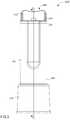
- FIG. 2is a front view of a bodily-fluid transfer device according to an embodiment, in a first configuration.
- FIG. 3is a side view of the bodily-fluid transfer device of FIG. 2 .
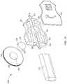
- FIG. 4is an exploded view of the bodily-fluid transfer device of FIG. 2 .
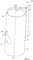
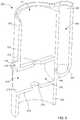
- FIG. 5is a perspective view of a housing included in the bodily-fluid transfer device illustrated in FIG. 2 .
- FIG. 6is a cross-sectional view of the housing illustrated in FIG. 5 taken along the line X 2 -X 2 .
- FIG. 7is a perspective view of a diverter and an actuator included in the bodily-fluid transfer device of FIG. 2 .
- FIG. 8is a cross-sectional view of the bodily-fluid transfer device of FIG. 2 taken along the line X 1 -X 1 , in a second configuration.
- FIG. 9is a cross-sectional view of the bodily-fluid transfer device of FIG. 2 taken along the line X 1 -X 1 , in a third configuration.
- FIG. 10is a perspective view of the bodily-fluid transfer device according to an embodiment.
- FIG. 11is an exploded view of the bodily-fluid transfer device of FIG. 10 .
- FIG. 12is a cross-sectional view of a housing included in the bodily-fluid transfer device of FIG. 10 taken along the line X 4 -X 4 in FIG. 11 .
- FIGS. 13-15are cross-sectional views of the bodily-fluid transfer device taken along the line X 4 -X 4 in FIG. 11 , in a first, second, and third configuration, respectively.
- a deviceincludes a pre-sample reservoir, an actuator mechanism, and a diverter.
- the pre-sample reservoiris configured to be fluidically coupled to a needle to receive and isolate a predetermined volume of bodily-fluid withdrawn from the patient.
- the actuator mechanismis operably coupled to the pre-sample reservoir such that, when actuated, a negative pressure is formed in the pre-sample reservoir that urges the bodily-fluid to flow into the pre-sample reservoir.
- the diverteris configured to selectively control fluid flow between the needle and the pre-sample reservoir.
- the diverterincludes a flow control mechanism that defines a first fluid flow path and a second fluid flow path.
- the diverteris configured to be moved between a first configuration in which the bodily-fluid can flow through the first fluid flow path to the pre-sample reservoir, and a second configuration in which the bodily-fluid can flow through the second fluid flow path to a sample reservoir coupled to the diverter.
- a method for procuring bodily-fluid samples from a patient using a parenterally sampling devicethat includes an actuation mechanism, a flow control mechanism and a pre-sample reservoir includes establishing fluid communication between a patient and the pre-sample reservoir.
- a first volume of bodily-fluidis withdrawn by moving the actuation mechanism from a first position to a second position to create a negative pressure in the pre-sample reservoir.
- the flow control mechanismis moved from a first configuration in which bodily-fluid is allowed to flow through a first flow path from the patient to the pre-sample reservoir to a second configuration in which bodily-fluid is allowed to flow through a second flow path from the patient to a sample reservoir.
- a bodily-fluid sampling deviceincludes a pre-sample reservoir, a diverter mechanism, and an actuator.
- the pre-sample reservoiris configured to be fluidically coupled to a needle.
- the pre-sampleis configured to have a negative pressure and configured to receive and isolate a predetermined volume of bodily-fluid withdrawn from a patient, via the needle.
- the diverter mechanismis configured to be fluidically coupled to the pre-sample reservoir.
- the diverter mechanismincludes a flow control mechanism configured for rotational movement between a first configuration in which the flow control mechanism and the diverter mechanism collectively define a first fluid flow path between the needle and the pre-sample reservoir and a second configuration in which the flow control mechanism and the diverter mechanism collectively define a second fluid flow path between the needle and a sample reservoir operably coupled to the diverter mechanism.
- the actuatoris rotatably coupled to the diverter mechanism and configured to be rotated from a first position, wherein the flow control mechanism is in the first configuration, to a second position, wherein the flow control mechanism is in the second configuration.
- a method for procuring bodily-fluid samples from a patient using a parenterally sampling device that has a flow control mechanism and an integrated pre-sample reservoir having a negative pressureincludes inserting a needle into the patient while the flow control mechanism is in a first configuration.
- the first configuration of the flow control mechanismis operable in preventing bodily-fluid from flowing from the patient to the integrated pre-sample reservoir.
- the flow control mechanismis moved from the first configuration to a second configuration.
- the second configuration of the flow control mechanismis operable in allowing bodily-fluid to flow through a first flow path defined at least in part by the flow control mechanism to the pre-sample reservoir.
- the methodincludes moving the flow control mechanism from the second configuration to a third configuration.
- the third configuration of the flow control mechanismis operable in allowing bodily-fluid to flow through a second flow path defined at least in part by the flow control mechanism to a sample reservoir.
- an apparatusin some embodiments, includes a diverter, a flow control mechanism, and an actuator mechanism.
- the diverterdefines an inlet port, a first outlet port, and a second outlet port.
- the first outlet portis fluidically coupled to a first fluid reservoir and the second outlet port is fluidically coupled to a second reservoir, fluidically isolated from the first fluid reservoir.
- the flow control mechanismis configured to be operably coupled to the diverter. In use, the flow control mechanism is moved between a first configuration, in which a flow of bodily-fluid can enter the first fluid reservoir, and a second configuration, in which a flow of bodily-fluid can enter the second fluid reservoir.
- a bodily-fluid transfer devicecan be configured to selectively divert a first, predetermined amount of a flow of a bodily-fluid to a first reservoir before permitting the flow of a second amount of the bodily-fluid into a second reservoir.
- the second amount of bodily-fluidcan be used for diagnostic or other testing, while the first amount of bodily-fluid, which may contain microbes from a bodily surface, is isolated from the second amount of the bodily-fluid.
- the first amount of bodily fluidcan be discarded or used for non-culture tests, such as one or more biochemical tests, blood counts, immunodiagnostic tests, cancer-cell detection tests, and the like where microbes from a bodily surface do not affect the test results.
- “bodily-fluid”can include any fluid obtained from a body of a patient, including, but not limited to, blood, cerebrospinal fluid, urine, bile, lymph, saliva, synovial fluid, serous fluid, pleural fluid, amniotic fluid, and the like, or any combination thereof.
- setcan refer to multiple features or a singular feature with multiple parts.
- the set of wallscan be considered as one wall with distinct portions, or the set of walls can be considered as multiple walls.
- a monolithically constructed itemcan include a set of walls.
- Such a set of wallscan include, for example, multiple portions that are discontinuous from each other.
- a set of wallscan also be fabricated from multiple items that are produced separately and later joined together (e.g., via a weld, an adhesive or any suitable method).
- proximal and distalrefer to the direction closer to and away from, respectively, a user who would place the device into contact with a patient.
- distal endthe end of a device first touching the body of the patient
- opposite end of the devicee.g., the end of the device being manipulated by the user
- FIG. 1is a schematic illustration of a portion of a bodily-fluid transfer device 100 , according to an embodiment.
- the bodily-fluid transfer device 100(also referred to herein as “fluid transfer device” or “transfer device”) is configured to permit the withdrawal of bodily-fluid from a patient such that a first portion, amount, or volume of the withdrawn fluid is diverted away from a second portion, amount, or volume of the withdrawn fluid that is to be used as a biological sample, such as for testing for the purpose of medical diagnosis and/or treatment where contamination from microbes or other contaminants exterior to the bodily-fluid source dermally-residing microbes) can affect test results.
- the transfer device 100is configured to transfer a first, predetermined amount of a bodily-fluid to a first collection reservoir and a second amount of bodily-fluid to one or more bodily-fluid collection reservoirs that are fluidically isolated from the first collection reservoir, as described in more detail herein.
- the transfer device 100includes a diverter 120 , a first reservoir 170 , and a second reservoir 180 , fluidically isolated from the first reservoir 170 .
- the diverter 120includes an inlet port 122 and two or more outlet ports, such as a first outlet port 124 and a second outlet port 126 , as shown in FIG. 1 .
- the inlet port 122is configured to be fluidically coupled to a medical device defining a pathway P for withdrawing and/or conveying the bodily-fluid from the patient to the transfer device 100 .
- the inlet port 122can be fluidically coupled to a needle, a fluid deliver member, or other lumen-containing device (e.g., flexible sterile tubing).
- the diverter 120can receive the bodily-fluid from the patient via the needle, other lumen-containing devices (e.g., cannula, catheters, etc.), or any other device suitable for collection of bodily-fluid samples from a patient.
- other lumen-containing devicese.g., cannula, catheters, etc.
- the first outlet port 124 of the diverter 120is configured to be fluidically coupled to the first reservoir 170 .
- the first reservoir 170is monolithically formed with the first outlet port 124 and/or a portion of the diverter 120 .
- the first reservoir 170can be mechanically and fluidically coupled to the diverter 120 via an adhesive, a resistance fit, a mechanical fastener, any number of mating recesses, a threaded coupling, and/or any other suitable coupling or combination thereof.
- the first reservoir 170can be physically (e.g., mechanically) coupled to the diverter 120 such that an interior volume defined by the first reservoir 170 is in fluid communication with the first outlet port 124 of the diverter 120 .
- the first reservoir 170can be operably coupled to the first outlet port 124 of the diverter 120 via an intervening structure (not shown in FIG. 1 ), such as a flexible sterile tubing. More particularly, the intervening structure can define a lumen configured to place the first reservoir 170 in fluid communication with the first outlet port 124 .
- the first reservoir 170is configured to receive and contain the first, predetermined amount of the bodily-fluid. In some embodiments, the first reservoir 170 is configured to contain the first amount of the bodily-fluid such that the first amount is fluidically isolated (or sequestered) from a second amount of the bodily-fluid that is subsequently withdrawn from the patient.
- the first reservoir 170can be any suitable reservoir for containing a bodily-fluid, such as a pre-sample reservoir described in detail in U.S. Patent Publication No. 2008/0145933 (“the '933 Publication”), the disclosure of which is incorporated herein by reference in its entirety.
- the first reservoircan be an evacuated sample tube (e.g., BD Vacutainer®) of sufficient size to collect the first amount of bodily fluid.
- first, predetermined amountand “first amount” describe an amount of bodily-fluid configured to be received or contained by the first reservoir 170 .
- first amountdoes not explicitly describe a predetermined amount, it should be understood that the first amount is the first, predetermined amount unless explicitly described differently.
- the second outlet port 126 of the diverter 120is configured to be fluidically coupled to the second reservoir 180 .
- the second reservoir 180is monolithically formed with the second outlet port 126 and/or a portion of the diverter 120 .
- the second reservoir 180can be mechanically coupled to the second outlet port 126 of the diverter 120 or operably coupled to the second outlet port 126 via an intervening structure (not shown in FIG. 1 ), such as described above with reference to the first reservoir 170 .
- the second reservoir 180is configured to receive and contain the second amount of the bodily-fluid.
- the second amount of bodily-fluidcan be an amount withdrawn from the patient subsequent to withdrawal of the first amount.
- the second reservoir 180is configured to contain the second amount of the bodily-fluid such that the second amount is fluidically isolated from the first amount of the bodily-fluid.
- the second reservoir 180can be any suitable reservoir for containing a bodily-fluid, including, for example, a sample reservoir as described in the '933 Publication incorporated by reference above.
- the term “second amount”describes an amount of bodily-fluid configured to be received or contained by the second reservoir 180 .
- the second amountcan be any suitable amount of bodily-fluid and need not be predetermined.
- the second amount received and contained by the second reservoir 180is a second, predetermined amount.
- the first reservoir 170 and the second reservoir 180can be coupled to (or formed with) the diverter 120 in a similar manner. In other embodiments, the first reservoir 170 and the second reservoir 180 need not be similarly coupled to the diverter 120 .
- the first reservoir 170can be monolithically formed with the diverter 120 (e.g., the first outlet port 124 ) and the second reservoir 180 can be operably coupled to the diverter 120 (e.g., the second outlet port 126 ) via an intervening structure, such as a flexible sterile tubing.
- the first reservoir 170can be monolithically formed with the diverter 120 and the second fluid reservoir 180 can be removably coupled to the diverter 120 .
- the transfer device 100further includes an actuator 140 and a flow control mechanism 130 first lumen 138 second lumen 139 .
- the actuator 140can be included in or otherwise operably coupled to the diverter 120 .
- the actuator 140can be configured to control a movement of the flow control mechanism 130 (e.g., between a first configuration and a second configuration).
- the actuator 140can be movable between a first position corresponding to the first configuration of the flow control mechanism 130 , and a second position, different than the first position, corresponding to the second configuration of the flow control mechanism 130 .
- the actuator 140is configured for uni-directional movement.
- the actuator 140can be moved from its first position to its second position, but cannot be moved from its second position to its first position. In this manner, the flow control mechanism 130 is prevented from being moved to its second configuration before its first configuration, thus requiring that the first amount of the bodily-fluid be directed to the first reservoir 170 and not the second reservoir 180 , as described in further detail herein.
- the flow control mechanism 130defines a first lumen 138 and a second lumen 139 .
- the flow control mechanism 130is configured such that when in the first configuration, the first lumen 138 fluidically couples the inlet port 122 to the first outlet port 124 and when in the second configuration, the second lumen 139 fluidically couples the inlet port 122 to the second outlet port 126 .
- the first lumen 138defines at least a portion of a first fluid flow path between the inlet port 122 and the first outlet port 124
- the second lumen 139defines at least a portion of a second fluid flow path between the inlet port 122 and the second outlet port 126 .
- the actuator 140is coupled to the flow control mechanism 130 and is configured to move the flow control mechanism 130 in a translational motion between the first configuration and the second configuration.
- the flow control mechanism 130can be in the first configuration when the flow control mechanism 130 is in a distal position relative to the transfer device 100 .
- the actuator 140can be actuated to move the flow control device 130 in the proximal direction to a proximal position relative to the transfer device 100 , thereby placing the flow control mechanism 130 in the second configuration.
- the actuator 140can be actuated to move the flow control mechanism 130 in a rotational motion between the first configuration and the second configuration.
- the second outlet port 126is fluidically isolated from the inlet port 122 .
- the first outlet port 124is fluidically isolated from the inlet port 122 .
- the flow control mechanism 130can direct, or divert the first amount of the bodily-fluid to the first reservoir 170 via the first outlet port 124 when the flow control mechanism 130 is in the first configuration and can direct, or divert the second amount of the bodily-fluid to the second reservoir 180 via the second outlet port 126 when the flow control mechanism 130 is in the second configuration.
- the actuator 140can be operably coupled to the first reservoir 170 , in this manner, the actuator 140 (or at least the portion of the actuator 140 ) can be configured to introduce or otherwise facilitate the development of a vacuum within the first reservoir 170 , thereby initiating flow of the bodily-fluid through the transfer device 100 and into the first reservoir 170 when the diverter 120 is in its first configuration.
- the actuator 140can include any suitable mechanism for actuating the transfer device 100 (e.g., at least the flow control mechanism 130 ) such as, for example, a rotating disc, a plunger, a slide, a dial, a button, a handle, a lever, and/or any other suitable mechanism or combination thereof. Examples of suitable actuators are described in more detail herein with reference to specific embodiments.
- the diverter 120can be configured such that the first amount of bodily-fluid need be conveyed to the first reservoir 170 before the diverter 120 will permit the flow of the second amount of bodily-fluid to be conveyed through the diverter 120 to the second reservoir 180 .
- the diverter 120can be characterized as requiring compliance by a health care practitioner regarding the collection of the first, predetermined amount (e.g., a pre-sample) prior to a collection of the second amount (e.g., a sample) of bodily-fluid.
- the diverter 120can be configured to prevent a health care practitioner from collecting the second amount, or the sample, of bodily-fluid into the second reservoir 180 without first diverting the first amount, or pre-sample, of bodily-fluid to the first reservoir 170 .
- the health care practitioneris prevented from including (whether intentionally or unintentionally) the first amount of bodily-fluid, which is more likely to contain bodily surface microbes (for example, dermally-residing microbes), in the bodily-fluid sample to be used for analysis.
- the fluid transfer device 100need not include a forced-compliance feature or component.
- the actuator 140can have a third position, different than the first and second positions, which can correspond to a third configuration of the flow control mechanism 130 .
- the flow control mechanism 130can fluidically isolate the inlet port 122 from both the first outlet port 124 and the second outlet port 126 simultaneously. Therefore, when the flow control mechanism 130 is in its third configuration, flow of bodily-fluid from the inlet port 122 to either the first reservoir 170 or the second reservoir 180 is prevented.
- the actuator 140can be actuated to place the flow control mechanism 130 in the first configuration such that a bodily-fluid can flow from the inlet port 122 to the first reservoir 170 , then moved to the second configuration such that the bodily-fluid can flow from the inlet port 122 to the second reservoir 180 , then moved to the third configuration to stop the flow of bodily-fluid into and/or through the diverter 120 .
- the flow control mechanism 130can be moved to the third configuration between the first configuration and the second configuration.
- the flow control mechanism 130can be in the third configuration before being moved to either of the first configuration or the second configuration.
- the flow control mechanism 130can be moved between four configurations.
- the flow control mechanism 130can be disposed in the third configuration and moved through the first configuration and second configuration to the fourth configuration.
- the fourth configurationcan function similarly to the third configuration to fluidically isolate the inlet port 122 from the first outlet port 124 and the second outlet portion 126 .
- one or more portions of the transfer device 100are disposed within a housing (not shown in FIG. 1 ).
- a housingnot shown in FIG. 1 .
- at least a portion of one or more of the diverter 120 , the first reservoir 170 , and the actuator 140can be disposed within the housing. In such an embodiment, at least a portion of the actuator 140 is accessible through the housing. Examples of suitable housings are described in more detail herein with reference to specific embodiments.
- FIGS. 2-9illustrate a transfer device 200 according to an embodiment.
- the transfer device 200includes a housing 201 , a diverter 220 , and an actuator 240 .
- the transfer device 200can be any suitable shape, size, or configuration.
- the transfer device 200can be square, rectangular, polygonal, and/or any other non-cylindrical shape.
- the housing 201includes a proximal end portion 202 , a distal end portion 203 , a first set of walls 204 , and a second set of wall 212 (also referred to herein as “inner walls” 212 ).
- the distal end portion 203 of the housing 201is coupled to a container shroud 218 configured to receive at least a portion of an external fluid reservoir (not shown in FIGS. 2-9 ).
- the container shroud 218can be coupled to the housing 201 in any suitable manner. For example, in some embodiments, a portion of the container shroud 218 can form a friction fit within a portion of the housing 201 .
- the container shroud 218can be coupled to the housing 201 via a threaded coupling, an adhesive, a snap fit, a mechanical fastener and/or any other suitable coupling method.
- the container shroud 218is monolithically formed with the housing 201 .
- the container shroud 218is configured to house a portion of an outlet adapter 229 ( FIG. 4 ) such that when the external fluid reservoir is disposed within the container shroud 218 , the external reservoir can be placed in fluid communication with the outlet adapter 229 , as described in further detail herein.
- the proximal end portion 202 of the housing 201receives the diverter 220 and is coupled to a cap 255 .
- the cap 255is configured to substantially enclose a portion of the housing 201 (see for example, the exploded view of FIG. 3 ).
- the cap 255is coupled to the proximal end portion 202 of the housing 201 such that the proximal end portion 202 is substantially closed.
- the walls 204include a pivot protrusion 209 configured to extend substantially perpendicularly from an outer surface of the walls 204 .
- the pivot protrusion 209defines an aperture 210 and is configured to receive a portion of the actuator 240 to pivotally couple the actuator 240 to the housing 201 .
- the walls 204define an inner volume 211 and a bypass chamber 205 .
- the bypass chamber 205includes a first end portion 206 and a second end portion 207 . More specifically, the first end portion 206 is disposed at the proximal end portion 202 of the housing 201 and is substantially open such that a bodily-fluid can flow through the first end portion 206 and into the bypass chamber 205 .
- the second end portion 207defines a lumen 208 configured to place the bypass chamber 205 in fluid communication with a volume of the housing 201 substantially outside of the bypass chamber 205 .
- the inner walls 212extend from an inner surface of the walls 204 of the housing 201 to substantially traverse a portion of the inner volume 211 . More specifically, the inner walls 212 are substantially annular and define a plunger volume 213 therebetween. The inner walls 212 also define a first opening 214 and a second opening 215 . The first opening 214 and the second opening 215 are configured to receive a portion of the diverter 220 , such that the portion of the diverter 220 can extend substantially continuously from the proximal end portion 202 of the housing 201 to the distal end portion 203 of the housing 201 .
- the portion of the diverter 220can transfer a bodily-fluid through the housing 201 to an external reservoir while fluidically isolating the bodily-fluid from a volume substantially outside the portion of the diverter 220 , as further described herein.
- the plunger volume 213is configured to extend through a portion of the walls 204 of the housing 201 such that the plunger volume 213 is open to a volume substantially outside of the housing 201 .
- the walls 204define an opening 216 configured to be disposed relative to the inner watts 212 to substantially align the opening 216 with a first end of the plunger volume 213 .
- the arrangement of the inner walls 212 relative to the housing 201is such that the opening 216 and the plunger volume 213 are defined in a distal position relative to the pivot protrusion 209 , as further described herein.
- the inner walls 212are configured such that a second end of the plunger volume 213 , opposite the first end, is in fluid communication with the lumen 208 of the bypass chamber 205 .
- a fluid reservoir 270configured to receive a flow of bodily-fluid, as described in further detail herein.
- the diverter 220includes a diverter plate 221 A, a transfer tube 228 , the outlet adapter 229 , and a flow control mechanism 230 (also referred to herein as “inlet port”).
- the diverter plate 221 Ais configured to engage a surface of the proximal end portion 202 of the housing 201 to retain the diverter plate 221 A relative to the housing 201 .
- the proximal end portion 202 of the housing 201can include a flange configured to receive a portion of the diverter plate 221 A.
- the diverter plate 221 Acan form a friction fit with an inner surface of the walls 204 of the housing 201 , thereby coupling the diverter plate 221 A to the housing 201 .
- at least a portion of the diverter plate 221 Acan be formed from a relatively flexible material such as a rubber or silicone. In this manner, the portion of the diverter plate 221 A can be configured to form a substantially fluid tight seal with the inner surface of the walls 204 .
- the diverter plate 221 Acan be coupled to the housing 201 via an adhesive. In such embodiments, the adhesive can be configured to form a substantially fluid tight or hermetic seal.
- the diverter plate 221 Adefines a first port 224 and a second port 226 .
- the first port 224is in fluid communication with the bypass chamber 205 of the housing 201 .
- the second port 226is in fluid communication with the outlet adapter 229 via the transfer tube 228 .
- a first end of the transfer tube 228is physically and fluidically coupled to the second port 226 of the diverter plate 221 A and a second end of the transfer tube 228 is physically and fluidically coupled to the outlet adapter 229 , thereby defining a fluid flow path between the second port 226 and the outlet adapter 229 .
- the transfer tube 228is configured to extend from the proximal end portion 202 of the housing 201 to the distal end portion 203 of the housing 201 via the first opening 214 and the second opening 215 defined by the inner walls 212 .
- the transfer tube 228can be configured to transfer a bodily-fluid from the flow control mechanism 230 to an external fluid reservoir, when the external fluid reservoir is fluidically coupled to the outlet adapter 229 .
- the flow control mechanism 230(e.g., the inlet port) defines a lumen 238 and is movable between a first position and a second position. More specifically, the flow control mechanism 230 is at least partially disposed within a channel 260 defined by the cap 255 (see e.g., FIG. 4 ).
- the lumen 238is substantially aligned with and in fluid communication with the first port 224 defined by the diverter plate 221 A.
- the lumen 238is configured to be substantially aligned with and in fluid communication with the second port 226 defined by the diverter plate 221 A.
- the flow control mechanism 230is configured to be manually moved between the first position and the second position via a force applied by a user (e.g., a medical professional). In other embodiments, the flow control mechanism 230 can be moved automatically by a portion of the transfer device 200 (e.g., the actuator 240 or any other suitable component).
- the actuator 240includes a lever 241 and a plunger 248 .
- the actuator 240is configured to be moved between a first configuration and a second configuration.
- the lever 241has a proximal end portion 242 , a distal end portion 243 , a pivot portion 245 , and an engagement portion 244 .
- the pivot portion 245is configured to be pivotally coupled to the pivot protrusion 209 of the housing 201 .
- a pivot pin(not shown) can be inserted through the pivot portion 245 of the lever 241 and the aperture 210 defined by the pivot protrusion 209 .
- the engagement portion 244 of the lever 241is configured to be movably coupled to an engagement portion 249 of the plunger member 248 .
- the lever 241can be actuated (e.g., pivoted) about the pivot portion 245 to move the plunger 248 between a first position and a second position, as described in further detail herein.
- the plunger 248is disposed within the plunger volume 213 and includes the engagement portion 249 and a seal member 254 . More specifically, the plunger 248 can be movably disposed within the plunger volume 213 such that the engagement portion 249 extends through the opening 216 defined by the walls 204 .
- the seal member 254is disposed within the plunger volume 213 and engages the inner walls 212 to form a substantially fluid tight seal.
- the plunger 248also defines a slot 251 configured to receive the transfer tube 228 of the diverter 220 .
- the slot 251enables the plunger 248 to move about the transfer tube 228 when the transfer tube 228 traverses the plunger volume 213 (e.g., passes through the first opening 214 and the second opening 215 defined by the inner walls 212 ).
- a usercan engage the transfer device 200 and couple the flow control mechanism 230 to a proximal end portion of a lumen-defining device (not shown) such as, for example, a butterfly needle.
- a lumen-defining devicesuch as, for example, a butterfly needle.
- the lumen 238is placed in fluid communication with the lumen defined by the lumen-defining device.
- the distal end portion of the lumen-defining devicecan be disposed within a portion of the body of a patient (e.g., a vein). In this manner, the lumen 238 is placed in fluid communication with the portion of the body.
- a usercan place the transfer device 200 in the first configuration by aligning the flow control mechanism 230 with the first port 224 defined by the diverter plate 221 A.
- the flow control mechanism 230is moved via manual intervention (e.g., a user slides the flow control mechanism 230 within the channel 260 to the first position).
- the flow control mechanism 230can be stored in the first configuration.
- the flow control mechanism 230can be placed in the first configuration via the actuator 240 (e.g., a user engaging the actuator 240 can urge the flow control mechanism 230 to move to the first configuration).
- the lumen 238is placed in fluid communication with the first port 224 when the flow control mechanism 230 is in the first configuration.
- the usercan apply an activation force to the lever 241 , thereby moving at least a portion of the actuator mechanism 240 towards the second configuration, as shown by the arrow AA in FIG. 8 .
- the usercan engage the housing 201 and the lever 241 and exert a squeezing force, thereby moving the proximal end portion 242 of the lever in the direction of the arrow AA.
- the squeezing force on the proximal end portion 242urges the lever 241 to pivot about the pivot protrusion 209 of the housing 201 and the pivot portion 245 of the lever 241 such that the distal end portion 243 moves in the direction of the arrow BB.
- the usercan pivot the lever 241 relative to the housing 201 such that the proximal end portion 242 is moved towards the housing 201 and the distal end portion 243 is moved away from the housing 201 .
- the arrangement of the plunger 248 , the lever 241 , and the inner walls 212is such that the pivoting motion of the distal end portion 243 of the lever 241 urges the plunger 248 to move in a translational motion within the plunger volume 213 defined by the inner walls 212 .
- the plunger 248is moved away from the bypass chamber 205 such that a volume of the fluid reservoir 270 is increased, thereby producing a negative pressure within the fluid reservoir 270 .
- the lumen 238 of the flow control mechanism 230 and the first port 224define a first fluid flow path that places the first end portion 206 of bypass chamber 205 in fluid communication with the flow control mechanism 230 .
- the fluid reservoir 270is placed in fluid communication with the portion of the patient (e.g., the vein).
- the negative pressure within the fluid reservoir 270 produced by the movement of the plunger 248introduces a suction force within the portion of the patient.
- a bodily-fluidis drawn through the first end portion 206 of the bypass chamber 205 and into the fluid reservoir 270 .
- the bodily-fluidcan contain undesirable microbes such as, for example, dermally-residing microbes.
- the magnitude of the suction forcecan be modulated by increasing or decreasing the amount of activation force (e.g., squeezing force) applied to the actuation mechanism 240 .
- activation forcee.g., squeezing force
- the usercan reduce the amount of force applied to the actuator 240 .
- the rate of changee.g., increase
- the volume of the fluid reservoir 270can be sufficiently slow to allow time for the negative pressure differential between the vein and the fluid reservoir 270 to come to equilibrium before further increasing the volume of the fluid reservoir 270 .
- the magnitude of the suction threecan be modulated.
- the actuator 240can be moved from the second configuration to a third configuration by reducing or removing the activation force on the proximal end portion 242 of the lever 241 .
- the actuator 240can include a spring (not shown) configured to exert a force to move the lever 241 toward the first position relative to the housing 201 , thereby placing the transfer device 200 in the third configuration.
- the usercan apply a squeezing force to the distal end portion 243 of the lever 241 such that the lever 241 pivots about the pivot portion 245 .
- the proximal end portion 242 of the lever 241is configured to move substantially away from the housing 201 as indicated by the arrow EE in FIG. 9 .
- the distal end portion 243 of the leveris configured to move substantially toward the housing 201 as indicated by the arrow FF in FIG. 9 .
- the movement of the distal end portion 243 of the lever 241can be such that the plunger 248 moves within the plunger volume 213 toward the bypass chamber 205 to reduce the negative pressure within the fluid reservoir 270 , as described above.
- the flow control mechanism 230can be moved in the direction of the arrow GG in FIG. 9 to place the lumen 238 in fluid communication with the second port 226 defined by the diverter plate 221 A.
- the flow control mechanism 230is moved within the channel 260 of the cap 255 to align the flow control mechanism 230 with the second port 226 .
- the alignment of the flow control mechanism 230 with the second port 226is such that the portion of the patient (e.g., the vein) is placed in fluid communication with the outlet adapter 229 via the transfer tube 228 .
- the outlet adapter 229can be coupled to an external fluid reservoir (not shown). Expanding further, the external fluid reservoir can be inserted into the container shroud 218 such that a portion of the outlet adapter 229 is disposed within the external fluid reservoir.
- the external fluid reservoircan be a BacT/ALERT® SN or a BacT/ALERT® FA, manufactured by BIOMERIEUX, INC.
- the outlet adapter 229can include a piercing member (not shown) such as a needle, configured to pierce a septum or membrane included in the fluid reservoir.
- the lumen 238 of the flow control mechanism 230 , the second port 226 , the transfer tube 228 , and the outlet adapter 229define a fluid flow path such that the external reservoir (not shown in FIG. 9 ) is in fluid communication with the flow control mechanism 230 and, therefore, the portion of the patient (e.g., the vein).
- the external reservoircan be configured to define a negative pressure (e.g., the known external reservoirs referred to herein are vessels defining a negative pressure).
- the negative pressure within the external reservoiris such that the negative pressure differential between the external reservoir and the portion of the body of the patient introduces a suction force within the portion of the patient. Therefore, a desired amount of bodily-fluid is drawn into the external reservoir and is fluidically isolated from the first, predetermined amount of bodily-fluid contained within the fluid reservoir 270 .
- the bodily-fluid contained in the external reservoiris substantially free from microbes generally found outside of the portion of the patient (e.g., dermally residing microbes, microbes within a lumen defined by the transfer device 200 , microbes within the lumen defined by the lumen defining device, and/or any other undesirable microbe).
- the usercan remove the external fluid reservoir from the transfer device 200 and dispose of the transfer device 200 or utilize the diversion sample contained within the fluid reservoir 270 for other types of testing and/or related medical or non-medical purposes.
- a transfer devicecan include a diverter and housing that are monolithically formed.
- FIGS. 10-15illustrate a transfer device 300 according to an embodiment. As shown in FIGS. 10 and 11 , the transfer device 300 includes a housing 301 , having a diverter 320 and defining a fluid reservoir 370 , a flow control mechanism 330 , and an actuator 340 .
- the housing 301includes a proximal end portion 302 , a distal end portion 303 , and a set of walls 304 . More particularly, the housing 301 includes a recessed surface 319 from which the walls 304 extend. Furthermore, at least a portion of the recessed surface 319 is configured to be a flat surface from which the diverter 320 can extend. Similarly stated, the diverter 320 is a set of walls configured to extend perpendicularly from the recessed surface 319 . In this manner, the diverter 320 can receive at least a portion of the flow control mechanism 330 , as described in further detail herein. While shown and described as extending perpendicularly from the recessed surface 319 , in other embodiments, the diverter 320 can extend from the recessed surface 319 at any suitable angular orientation.
- the diverter 320includes an inlet port 322 , a first outlet port 324 , and a second outlet port 326 , and defines and inner volume 321 .
- the inner volume 321is configured to extend through the recessed surface 319 such that the inner volume 321 is substantially open.
- the diverter 320is configured such that a set of walls that define the inner volume 321 are substantially cylindrical and define an open space therebetween (e.g., the inner volume 321 ).
- the inner volume 321is configured to receive at least a portion of the flow control mechanism 330 , as further described herein.
- the inlet port 322 of the diverter 320defines an inlet lumen 323 .
- the inlet lumen 323is configured to be in fluid communication with the inner volume 321 .
- the inlet lumen 323 of the inlet port 322extends through the wall defining the inner volume 321 of the diverter 320 .
- the inlet port 322is further configured to be fluidically coupled to a medical device (not shown) defining a fluid flow pathway fir withdrawing and/or conveying the bodily-fluid from a patient to the transfer device 300 .
- the inlet port 322can be fluidically coupled to a needle or other lumen-defining device (e.g., flexible sterile tubing) as described above.
- a needle or other lumen-defining devicee.g., flexible sterile tubing
- the first outlet port 324 of the diverter 320defines a first outlet lumen 325 .
- the first outlet lumen 325is in fluid communication with the inner volume 321 of the diverter 320 and the fluid reservoir 370 (described above).
- the first outlet lumen 325is configured to extend through the wall defining the inner volume 321 , thereby placing the fluid reservoir 370 in fluid communication with the inner volume 321 .
- the second outlet port 326 of the diverter 320defines a second outlet lumen 327 and is configured to be coupled to an external fluid reservoir.
- the second outlet lumen 327can extend through the wall defining the inner volume 321 to be in fluid communication with the inner volume 321 .
- the second outlet port 326can be fluidically coupled to the external reservoir to place the external fluid reservoir in fluid communication with the inner volume 321 via the second outlet lumen 327 , as described in further detail herein.
- the actuator mechanism 340includes an engagement portion 345 and an activation portion 346 .
- the actuator mechanism 340can be coupled to the housing 301 in any suitable manner.
- a portion of the actuator mechanism 340can be disposed within the inner volume 321 .
- the walls 304can include a feature e.g., a tab, a lock, and/or the like) configured to selectively retain the actuator mechanism 340 in contact with the housing 301 .
- the activation portion 346is configured to contact, mate, or otherwise engage the flow control mechanism 330 .
- the engagement portion 345can be engaged by a user to rotate the actuator mechanism 340 relative to the housing 301 to move the transfer device 300 between a first configuration, a second configuration, and a third configuration, as described in further detail herein.
- the flow control mechanism 330defines a first lumen 338 and a second lumen 339 and is disposed within the inner volume 321 defined by the diverter 320 .
- the flow control mechanism 330defines a circular cross-sectional shape such that when the flow control mechanism 330 is disposed within the inner volume 321 , a portion of the flow control mechanism 330 forms a friction fit with the walls of the diverter 320 defining the inner volume 321 .
- the flow control mechanism 330is formed from silicone and has a diameter larger than the diameter of the walls defining the inner volume 321 . As such, the diameter of the flow control mechanism 330 is reduced when the flow control mechanism 330 is disposed within the inner volume 321 .
- the outer surface of the flow control mechanism 330forms a friction fit with the inner surface of the walls defining the inner volume 321 .
- the flow control mechanism 330can be any suitable elastomer configured to deform when disposed within the inner volume 321 of the diverter 320 .
- the flow control mechanism 330can be coupled to and/or can otherwise engage the actuator 340 .
- the actuator 340can be coupled to the flow control mechanism 330 via a mechanical fastener and/or adhesive.
- the actuator 340 and the flow control mechanism 330can be coupled in any suitable manner such that the flow control mechanism 330 moves concurrently with the actuator 340 when the actuator 340 is rotated relative to the housing 301 . In this manner, the flow control mechanism 330 can be moved relative to the diverter 320 to place the first lumen 338 or the second lumen 339 in fluid communication with the inlet port 322 , the first outlet port 324 , and/or the second outlet port 326 , as described in further detail herein.
- the transfer device 300can be stored in the first configuration in which the flow control mechanism 330 fluidically isolates the inlet port 322 from the first outlet port 324 and the second outlet port 326 .
- the flow control mechanism 330can be disposed within the inner volume 321 of the diverter 320 such that the first lumen 338 and the second lumen 339 are fluidically isolated from the inlet lumen 323 , the first outlet lumen 325 , and the second outlet lumen 327 .
- the friction fit defined by the flow control mechanism 330 and the walls of the diverter 320 defining the inner volume 321maintain the flow control mechanism 330 in the first configuration until, for example, user intervention moves the actuator 340 , thereby moving the flow control mechanism 330 to the second configuration.
- a usercan manipulate the transfer device 300 to couple the inlet port 322 to a proximal end portion of a lumen-defining device (not shown) such as, for example, a butterfly needle and/or the like.
- a lumen-defining devicesuch as, for example, a butterfly needle and/or the like.
- the distal end portion of the lumen-defining devicecan be disposed within a portion of the body of a patient (e.g., a vein) to place the inlet lumen 323 in fluid communication with the portion of the body of the patient.
- the second outlet port 326can be coupled to an external fluid reservoir (not shown).
- the external fluid reservoircan be any suitable reservoir.
- the external fluid reservoircan be a BacT/ALERT® SN or a BacT/ALERT® FA, manufactured by BIOMERIEUX, INC.
- a usercan begin the transfer of a bodily-fluid by applying an activation force to the engagement portion 344 of the actuator 340 , thereby moving the actuator 340 to a second position, as shown by the arrow II in FIG. 14 .
- the movement of the actuator 340is such that the flow control member 340 is urged to move in the direction of the arrow II, thereby placing the transfer device 300 in the second configuration.
- the fluid reservoir 370can be configured such that a negative pressure exists within an inner volume 373 such as, for example, an evacuated sample tube (e.g., BD Vacutainer®).
- a negative pressure differentialintroduces a suction force within the first lumen 338 of the flow control mechanism 330 , and the inlet lumen 323 and the first outlet lumen 325 of the diverter 320 .
- the inlet lumen 323 of the inlet port 322 , the first lumen 338 of the flow control mechanism 330 , and the first outlet lumen 325 of the first outlet port 324define a first fluid flow path that places the inner volume 373 defined by the fluid reservoir 370 in fluid communication with the inlet port 322 . Furthermore, with the inlet port 322 coupled to the lumen-defining device, the first fluid flow path places the fluid reservoir 370 in fluid communication with the portion of the patient (e.g., the vein) and at least a portion of the suction force (e.g., applied by the negative pressure differential, as described above) is introduced to the portion of the patient.
- the portion of the patiente.g., the vein
- the suction forcee.g., applied by the negative pressure differential, as described above
- a bodily-fluidcan be drawn into the fluid reservoir 370 .
- the bodily-fluidcan contain undesirable microbes such as, for example, dermally-residing microbes dislodged during the insertion of the lumen-defining device.
- the magnitude of the suction forcecan be modulated by further moving the actuator 340 in the direction of the arrow II.
- the usercan move the actuator 340 and the flow control mechanism 330 (e.g., in the II direction) to constrict or otherwise reduce the size of at least a portion of the first fluid pathway (e.g., an inner diameter) between the inlet lumen 323 and the first lumen 338 and the first outlet lumen 325 and the first lumen 338 , thereby reducing the suction force introduced into the vein of the patient.
- the first fluid pathwaye.g., an inner diameter
- the transfer device 300can engage the transfer device 300 to move the transfer device 300 from the second configuration to the third configuration, wherein a flow of bodily-fluid is transferred to the external reservoir (e.g., such as those described above).
- the desired amount of bodily-fluid transferred to the fluid reservoir 370is a predetermined amount of fluid.
- the transfer device 300can be configured to transfer bodily-fluid until the pressure within the fluid reservoir 370 is equilibrium with the pressure of the portion of the body in which the lumen-defining device is disposed (e.g., the vein), as described above.
- the fluid reservoir 370can be transparent to allow visualization of the bodily fluid flowing into the fluid reservoir 370 .
- the fluid reservoir 370can include indicators (e.g., 0.1 mL, 0.5 mL, 1 mL, 2 mL, 3 mL, 4 mL, and/or 5 mL graduation marks) that the user can visualize to determine the volume of bodily-fluid that has been received in the fluid reservoir 370 .
- the transfer device 300can be moved from the second configuration to the third configuration by moving the actuator mechanism 340 in the direction of the arrow KK in FIG. 15 .
- the actuator mechanism 340rotates the flow control mechanism 330 toward the third configuration.
- the first lumen 338is fluidically isolated from the inlet lumen 323 and the first outlet lumen 325
- the second lumen 339is placed in fluid communication with the inlet lumen 323 defined by the inlet port 322 and the second outlet lumen 327 defined by the second outlet port 326 .
- the inlet lumen 323 of the inlet port 322 , the second lumen 339 of the flow control mechanism 330 , and the second outlet lumen 327 of the second outlet port 326define a second fluid flow path that can place the external reservoir (not shown in FIG. 15 ) in fluid communication with the inlet port 322 and, therefore, the portion of the patient (e.g., the vein).
- the external reservoircan be configured to define a negative pressure (e.g., the known external reservoirs referred to herein are vessels defining a negative pressure).
- the negative pressure within the external reservoiris such that the negative pressure differential between the external reservoir and the portion of the body of the patient introduces a suction force within the portion of the patient. Therefore, a desired amount of bodily-fluid is drawn into the external reservoir and is fluidically isolated from the first, predetermined amount of bodily-fluid contained within the fluid reservoir 370 .
- the bodily-fluid contained in the external reservoiris substantially free from microbes generally found outside of the portion of the patient (e.g., dermally residing microbes, microbes within a lumen defined by the transfer device 300 , microbes within the lumen defined by the lumen defining device, and/or any other undesirable microbe).
- the usercan further move the actuator 340 in the proximal direction to place the transfer device 300 in a fourth configuration.
- the actuator 340can be moved in the direction of the arrow KK to fluidically isolate the first lumen 338 and the second lumen 339 of the flow control mechanism 330 from the inlet lumen 323 , the first outlet lumen 325 , and the second outlet lumen 327 of the diverter 320 .
- the bodily-fluid contained within the fluid reservoir 370is fluidically isolated from a volume outside the fluid reservoir 370 and the external reservoir can be decoupled from the transfer device 300 .
- additional external reservoirscan then be fluidically coupled to the transfer device 300 , and the user can rotate the actuator 340 back to the third configuration to establish fluid communication between the patient and the additional external reservoir and/or sample vessel.
- the actuator 340can include a sensible indication (e.g., audible, visual and/or tactile) of which position the transfer device 300 is in.
- the actuatorcan include numeric indicators of the position of the transfer device 300 .
- the lever 241is described in reference to FIG. 9 as being returned to the first position relative to the housing 201 when the transfer device 200 is moved to the third configuration, in other embodiments, the lever 241 need not be moved from the second position relative to the housing 201 .
- the pressure differential between the vein and the fluid reservoir 270can be in equilibrium without substantially reducing the volume of the fluid reservoir 270 .
- the plunger 248need not be moved toward the bypass chamber 205 and the lever 241 of the actuator 240 can remain in the second position relative to the housing 201 while a bodily-fluid is transferred to an external reservoir.
- an actuatorcan be rotated in a first direction (e.g., in the direction of the arrow II in FIG. 14 ) and a second direction, opposite the first.
- the rotation in the second directioncan be configured to move a transfer device through any number of configurations.
- the rotation of the actuator in the second directioncan be limited.
- the actuatorcan be limitedly rotated in the second direction to reduce the diameter of a flow path between a flow control mechanism and a lumen such as to reduce a suction force, as described above.
- the actuatorcan include a mechanical stop or lock to fluidically isolate the first volume of bodily fluid received from the patient (i.e., the contaminated sample). Said another way, once the first reservoir is filed with a predetermined volume of bodily fluid and the user has moved the actuator to being drawing additional sample, the actuator cannot be moved back to establish fluid communication the first sample volume.
- transfer device 300is shown and described with respect to FIGS. 13-15 as having a first, second, third and forth configuration, in other embodiments, the transfer devices described herein may have more or fewer configurations.
- the specific configurations of the various componentscan also be varied.
- the size and specific shape of the various componentscan be different than the embodiments shown, while still providing the functions as described herein. More specifically, the size and shape of the various components can be specifically selected for a desired rate of bodily-fluid flow into a fluid reservoir.
Landscapes
- Health & Medical Sciences (AREA)
- Life Sciences & Earth Sciences (AREA)
- Engineering & Computer Science (AREA)
- Animal Behavior & Ethology (AREA)
- Public Health (AREA)
- Biomedical Technology (AREA)
- Heart & Thoracic Surgery (AREA)
- Medical Informatics (AREA)
- Molecular Biology (AREA)
- Surgery (AREA)
- Veterinary Medicine (AREA)
- General Health & Medical Sciences (AREA)
- Pathology (AREA)
- Hematology (AREA)
- Physics & Mathematics (AREA)
- Biophysics (AREA)
- Dermatology (AREA)
- Pain & Pain Management (AREA)
- Manufacturing & Machinery (AREA)
- Automatic Analysis And Handling Materials Therefor (AREA)
- Infusion, Injection, And Reservoir Apparatuses (AREA)
- Measurement Of The Respiration, Hearing Ability, Form, And Blood Characteristics Of Living Organisms (AREA)
Abstract
Description
Claims (19)
Priority Applications (2)
| Application Number | Priority Date | Filing Date | Title |
|---|---|---|---|
| US14/926,784US10881343B2 (en) | 2012-08-01 | 2015-10-29 | Fluid diversion mechanism for bodily-fluid sampling |
| US17/136,882US20210186392A1 (en) | 2012-08-01 | 2020-12-29 | Fluid diversion mechanism for bodily-fluid sampling |
Applications Claiming Priority (3)
| Application Number | Priority Date | Filing Date | Title |
|---|---|---|---|
| US201261678404P | 2012-08-01 | 2012-08-01 | |
| US13/952,964US9204864B2 (en) | 2012-08-01 | 2013-07-29 | Fluid diversion mechanism for bodily-fluid sampling |
| US14/926,784US10881343B2 (en) | 2012-08-01 | 2015-10-29 | Fluid diversion mechanism for bodily-fluid sampling |
Related Parent Applications (1)
| Application Number | Title | Priority Date | Filing Date |
|---|---|---|---|
| US13/952,964ContinuationUS9204864B2 (en) | 2012-08-01 | 2013-07-29 | Fluid diversion mechanism for bodily-fluid sampling |
Related Child Applications (1)
| Application Number | Title | Priority Date | Filing Date |
|---|---|---|---|
| US17/136,882ContinuationUS20210186392A1 (en) | 2012-08-01 | 2020-12-29 | Fluid diversion mechanism for bodily-fluid sampling |
Publications (2)
| Publication Number | Publication Date |
|---|---|
| US20160113560A1 US20160113560A1 (en) | 2016-04-28 |
| US10881343B2true US10881343B2 (en) | 2021-01-05 |
Family
ID=50026147
Family Applications (3)
| Application Number | Title | Priority Date | Filing Date |
|---|---|---|---|
| US13/952,964Active2033-08-30US9204864B2 (en) | 2012-08-01 | 2013-07-29 | Fluid diversion mechanism for bodily-fluid sampling |
| US14/926,784Active2035-03-08US10881343B2 (en) | 2012-08-01 | 2015-10-29 | Fluid diversion mechanism for bodily-fluid sampling |
| US17/136,882PendingUS20210186392A1 (en) | 2012-08-01 | 2020-12-29 | Fluid diversion mechanism for bodily-fluid sampling |
Family Applications Before (1)
| Application Number | Title | Priority Date | Filing Date |
|---|---|---|---|
| US13/952,964Active2033-08-30US9204864B2 (en) | 2012-08-01 | 2013-07-29 | Fluid diversion mechanism for bodily-fluid sampling |
Family Applications After (1)
| Application Number | Title | Priority Date | Filing Date |
|---|---|---|---|
| US17/136,882PendingUS20210186392A1 (en) | 2012-08-01 | 2020-12-29 | Fluid diversion mechanism for bodily-fluid sampling |
Country Status (2)
| Country | Link |
|---|---|
| US (3) | US9204864B2 (en) |
| WO (1) | WO2014022275A1 (en) |
Cited By (12)
| Publication number | Priority date | Publication date | Assignee | Title |
|---|---|---|---|---|
| US11737693B2 (en) | 2012-12-04 | 2023-08-29 | Magnolia Medical Technologies, Inc. | Sterile bodily-fluid collection device and methods |
| US11786155B2 (en) | 2019-02-08 | 2023-10-17 | Magnolia Medical Technologies, Inc. | Devices and methods for bodily fluid collection and distribution |
| US11819329B2 (en) | 2012-05-30 | 2023-11-21 | Magnolia Medical Technologies, Inc. | Fluid diversion mechanism for bodily-fluid sampling |
| US11857321B2 (en) | 2019-03-11 | 2024-01-02 | Magnolia Medical Technologies, Inc. | Fluid control devices and methods of using the same |
| US11890452B2 (en) | 2012-10-11 | 2024-02-06 | Magnolia Medical Technologies, Inc. | Systems and methods for delivering a fluid to a patient with reduced contamination |
| US11903709B2 (en) | 2017-09-12 | 2024-02-20 | Magnolia Medical Technologies, Inc. | Fluid control devices and methods of using the same |
| US11963769B2 (en) | 2015-07-24 | 2024-04-23 | Kurin, Inc. | Blood sample optimization system and blood contaminant sequestration device and method |
| US12083234B2 (en) | 2015-09-03 | 2024-09-10 | Magnolia Medical Technologies, Inc. | Apparatus and methods for maintaining sterility of a specimen container |
| US12186080B2 (en) | 2012-05-30 | 2025-01-07 | Magnolia Medical Technologies, Inc. | Fluid diversion mechanism for bodily-fluid sampling |
| US12257051B2 (en) | 2017-02-10 | 2025-03-25 | Kurin, Inc. | Blood contaminant sequestration device with one-way air valve and air-permeable blood barrier with closure mechanism |
| US12383174B2 (en) | 2019-04-01 | 2025-08-12 | Kurin, Inc. | Non-venting bodily fluid sample optimization device and system |
| US12390596B2 (en) | 2021-12-17 | 2025-08-19 | Kurin, Inc. | Syringes configured to inhibit forward plunger movement |
Families Citing this family (26)
| Publication number | Priority date | Publication date | Assignee | Title |
|---|---|---|---|---|
| US8197420B2 (en) | 2006-12-18 | 2012-06-12 | Magnolia Medical Technologies, Inc. | Systems and methods for parenterally procuring bodily-fluid samples with reduced contamination |
| US8864684B2 (en) | 2011-10-13 | 2014-10-21 | Magnolia Medical Technologies, Inc. | Fluid diversion mechanism for bodily-fluid sampling |
| US9204864B2 (en) | 2012-08-01 | 2015-12-08 | Magnolia Medical Technologies, Inc. | Fluid diversion mechanism for bodily-fluid sampling |
| CN109171766A (en) | 2012-11-30 | 2019-01-11 | 木兰医药技术股份有限公司 | Body fluid barrier means and the method for completely cutting off body fluid using body fluid barrier means |
| CA3183294A1 (en) | 2012-12-04 | 2014-06-12 | Magnolia Medical Technologies, Inc. | Sterile bodily-fluid collection device and methods |
| CN108433732B (en) | 2013-03-12 | 2021-05-28 | 木兰医药技术股份有限公司 | Apparatus and method for selectively occluding a lumen of a needle body |
| EP3721854B1 (en) | 2014-03-03 | 2023-04-05 | Magnolia Medical Technologies, Inc. | Apparatus and methods for disinfection of a specimen container |
| WO2016201406A1 (en) | 2015-06-12 | 2016-12-15 | Bullington Gregory J | Devices and methods for syringe-based fluid transfer for bodily-fluid sampling |
| CA2993992A1 (en)* | 2015-07-31 | 2017-02-09 | Medivance Incorporated | Urine output collection and monitoring system |
| WO2017160928A1 (en) | 2016-03-16 | 2017-09-21 | Dignity Health | Methods and apparatus for reducing contamination in blood draw samples |
| EP4154927B1 (en) | 2016-06-15 | 2025-01-29 | True Concepts Medical Technologies, Inc | Syringe systems for multi-stage fluid delivery |
| US11167085B2 (en) | 2016-06-15 | 2021-11-09 | True Concepts Medical Technologies, Llc | Syringe systems and methods for multi-stage fluid delivery |
| EP3777684B1 (en) | 2016-12-27 | 2022-06-29 | Kurin, Inc. | Blood contaminat sequestration device |
| US11617525B2 (en) | 2017-02-10 | 2023-04-04 | Kurin, Inc. | Blood contaminant sequestration device with passive fluid control junction |
| JP7229267B2 (en) | 2017-12-07 | 2023-02-27 | マグノリア メディカル テクノロジーズ,インコーポレイテッド | Fluid control device and method of use |
| JP2021524323A (en) | 2018-05-22 | 2021-09-13 | シー・アール・バード・インコーポレーテッドC R Bard Incorporated | Catheter insertion system and how to use it |
| EP4614117A2 (en) | 2018-08-10 | 2025-09-10 | C. R. Bard, Inc. | Automated urine-output-measurement systems and methods thereof |
| US11604204B2 (en)* | 2019-06-03 | 2023-03-14 | University Of Washington | Self-contained systems and methods for controlled dispensing of hazardous fluid |
| WO2021178910A1 (en) | 2020-03-06 | 2021-09-10 | Magnolia Medical Technologies, Inc. | Universal transfer adapters and methods of using the same |
| US12083261B2 (en) | 2020-06-05 | 2024-09-10 | C. R. Bard, Inc. | Automated fluid output monitoring |
| US11703365B2 (en) | 2020-07-14 | 2023-07-18 | C. R. Bard, Inc. | Automatic fluid flow system with push-button connection |
| US12055249B2 (en) | 2020-07-21 | 2024-08-06 | C. R. Bard, Inc. | Automatic fluid flow system with retractable connection |
| US12408853B2 (en) | 2020-12-17 | 2025-09-09 | C. R. Bard, Inc. | Smart bag to measure urine output via catheter |
| US12364423B2 (en) | 2020-12-21 | 2025-07-22 | C. R. Bard, Inc. | Automated urinary output-measuring systems and methods |
| US11931151B2 (en) | 2020-12-22 | 2024-03-19 | C. R. Bard, Inc. | Automated urinary output measuring system |
| US12246146B2 (en) | 2020-12-23 | 2025-03-11 | C. R. Bard, Inc. | Automated weight based fluid output monitoring system |
Citations (259)
| Publication number | Priority date | Publication date | Assignee | Title |
|---|---|---|---|---|
| US2707953A (en) | 1952-07-15 | 1955-05-10 | Abbott Lab | Transfusion equipment |
| US2992974A (en) | 1960-04-04 | 1961-07-18 | Allan S Belcove | Biological testing device |
| US3013557A (en) | 1959-04-13 | 1961-12-19 | Hazleton Lab Inc | Combination syringe, shipping container and centrifuge tube |
| US3098016A (en) | 1961-07-26 | 1963-07-16 | American Cyanamid Co | Process for producing sterile vials containing culture media and a carbon dioxide atmosphere |
| US3382865A (en) | 1965-10-18 | 1968-05-14 | Ashton L. Worrall Jr. | Device for taking multiple blood samples or the like |
| US3405706A (en) | 1965-04-22 | 1968-10-15 | Cinqualbre Paul | Arrangement for taking blood |
| US3467095A (en)* | 1967-04-24 | 1969-09-16 | Eugene Ross Lab Inc | Blood collection set |
| US3494351A (en) | 1966-06-21 | 1970-02-10 | Ferrell S Horn | Multiple vial fluid collecting device |
| US3494352A (en) | 1969-03-26 | 1970-02-10 | Becton Dickinson Co | Apparatus for taking multiple samples |
| US3577980A (en) | 1968-05-28 | 1971-05-11 | Milton J Cohen | Fluid extraction device |
| US3604410A (en) | 1968-09-11 | 1971-09-14 | Gary L Whitacre | Multitube blood sampler |
| US3635798A (en) | 1969-03-24 | 1972-01-18 | William R Kirkham | Blood and fluid culturing system |
| US3648684A (en) | 1970-08-04 | 1972-03-14 | Cleora W Barnwell | Device for the direct transfer of blood from a human to culture bottles |
| US3741197A (en) | 1970-09-04 | 1973-06-26 | Micromedia Syst Inc | Percussion apparatus for blood sampling |
| US3777773A (en) | 1972-02-22 | 1973-12-11 | Koehring Co | Pressure compensating valve mechanism |
| US3817240A (en) | 1972-06-28 | 1974-06-18 | Becton Dickinson Co | Multiple sample needle assembly with one-way valve and blood flow indicator |
| US3834372A (en) | 1973-01-12 | 1974-09-10 | S Turney | Disposable manifold with atmospheric vent |
| US3835835A (en) | 1972-11-07 | 1974-09-17 | Richardson Merrell Inc | Two compartment locking sampling syringe |
| US3848581A (en) | 1971-10-08 | 1974-11-19 | L Cinqualbre | Apparatus for taking multiple samples of biological liquid |
| US3848579A (en) | 1973-02-23 | 1974-11-19 | Real A Villa | Automatic elasto-valvular hypodermic sampling needle |
| US3874367A (en) | 1972-06-29 | 1975-04-01 | Becton Dickinson Co | Valved blood sampling needle assembly |
| US3886930A (en) | 1971-04-30 | 1975-06-03 | Abbott Lab | Blood collecting assembly |
| US3890203A (en) | 1972-01-06 | 1975-06-17 | Becton Dickinson Co | Method and apparatus for the collection, cultivation and identification of microorganisms from body fluid |
| US3890968A (en) | 1971-06-25 | 1975-06-24 | Sci Systems Inc | Fluid flow control means |
| US3937211A (en) | 1972-10-27 | 1976-02-10 | Fa. Walter Sarstedt Kunststoff-Spritzgusswerk | Multi-purpose syringe |
| US3945380A (en) | 1974-08-21 | 1976-03-23 | Cutter Laboratories, Inc. | Plasmapheresis assembly |
| US3978846A (en) | 1975-01-02 | 1976-09-07 | Bailey Donald L | Syringe for taking blood samples |
| DE2541494A1 (en) | 1975-08-18 | 1977-03-31 | Guerra Luis A | Hypodermic needle blood taking device - has valves at needle end and at attachable evacuated chamber connection |
| DE2203858B2 (en) | 1971-11-05 | 1977-10-27 | Immuno AG für chemisch-medizinische Produkte, Wien | Combined blood withdrawal and transfusion appts - for obtaining blood plasma by plasmaphaeresis |
| US4056101A (en) | 1976-09-01 | 1977-11-01 | Baxter Travenol Laboratories, Inc. | Means for reducing tissue thromboplastin in collected blood |
| US4057050A (en) | 1974-11-29 | 1977-11-08 | Sarstedt W | Devices for extracting blood |
| US4063460A (en) | 1975-08-28 | 1977-12-20 | Jan Axel Svensson | Method for evacuating and then collecting medium samples in containers sealed by a resilient stopper at substantially atmospheric pressure |
| US4077395A (en) | 1975-10-15 | 1978-03-07 | St. Thomas's Hospital Medical School | Apparatus for taking blood samples from a living patient |
| US4106497A (en) | 1977-02-04 | 1978-08-15 | Becton, Dickinson And Company | Multiple sample needle assembly with indicator means |
| US4133863A (en) | 1977-03-23 | 1979-01-09 | Sherwood Medical Industries, Inc. | Collection tube assembly and method for collecting biological fluids |
| US4150089A (en) | 1977-09-06 | 1979-04-17 | Linet Michael S | Multi-chamber test tube |
| US4154229A (en) | 1977-08-10 | 1979-05-15 | Becton, Dickinson And Company | Blood collection system with venipuncture indicator |
| US4166450A (en) | 1977-07-22 | 1979-09-04 | Metatech Corporation | Device and procedure for collecting a succession of intravenous blood samples |
| US4193400A (en) | 1978-06-16 | 1980-03-18 | The Deseret Company | Intravenous needle assembly with air bleed plug |
| US4207870A (en) | 1978-06-15 | 1980-06-17 | Becton, Dickinson And Company | Blood sampling assembly having porous vent means vein entry indicator |
| US4212308A (en) | 1977-12-27 | 1980-07-15 | Becton, Dickinson And Company | Parallel-flow one-way blood sampling device |
| US4257416A (en) | 1979-05-03 | 1981-03-24 | David Prager | Multi-channel venipuncture infusion set |
| US4275730A (en) | 1979-11-05 | 1981-06-30 | Becton, Dickinson And Company | Syringe with pressure-limited delivery |
| US4340067A (en) | 1980-03-31 | 1982-07-20 | Rattenborg Christen C | Blood collection syringe |
| US4340068A (en) | 1980-06-18 | 1982-07-20 | Becton, Dickinson And Company | Multiple sample needle with vein entry indicator |
| US4349035A (en) | 1978-03-14 | 1982-09-14 | Johnson & Johnson | Blood collection assembly with unidirectional flow valve |
| US4370987A (en) | 1980-10-07 | 1983-02-01 | Seymour Bazell | Medical fluid collection device |
| US4398544A (en) | 1981-10-15 | 1983-08-16 | Becton Dickinson And Company | Single and multiple sample needle assembly with vein entry indicator |
| US4412548A (en) | 1981-07-30 | 1983-11-01 | Becton Dickinson And Company | Multiple sample needle assembly |
| US4416290A (en) | 1982-08-30 | 1983-11-22 | Becton Dickinson And Company | Multiple sample needle assembly with vein indication |
| US4425235A (en) | 1982-03-22 | 1984-01-10 | Sherwood Medical Company | Blood collection device with phase partitioning means |
| US4444203A (en) | 1982-03-26 | 1984-04-24 | Lab-A-Cath, Inc. | Intravenous catheter placing and specimen gathering device |
| US4459997A (en) | 1981-11-03 | 1984-07-17 | Walter Sarstedt Kunststoff-Spritzgusswerk | Blood extracting and centrifuging device |
| US4509534A (en) | 1982-06-14 | 1985-04-09 | Tassin Jr Myron J | Blood withdrawal apparatus and method of using same |
| US4537593A (en) | 1983-06-06 | 1985-08-27 | Becton, Dickinson And Co. | Self-venting, non-coring needle assembly |
| US4608996A (en) | 1984-08-10 | 1986-09-02 | Cordis Corporation | External blood parameter diagnostic system |
| WO1986005568A1 (en) | 1985-03-15 | 1986-09-25 | Jan Axel Svensson | Slide valve and coupler assembly |
| EP0207304A1 (en) | 1985-05-31 | 1987-01-07 | TERUMO KABUSHIKI KAISHA trading as TERUMO CORPORATION | Blood reservoir |
| US4654027A (en)* | 1985-10-30 | 1987-03-31 | Dragan William B | Vascular dilating device |
| US4657160A (en) | 1984-09-13 | 1987-04-14 | Andy Woods | Pressure infusion control |
| US4657027A (en) | 1984-02-04 | 1987-04-14 | Ferring Biotechnik Gmbh | Means for taking blood samples for the diagnosis of bodily functions |
| US4673386A (en) | 1986-03-06 | 1987-06-16 | Gordon Mark G | Blood sampler device |
| US4676256A (en) | 1986-03-24 | 1987-06-30 | Golden Theodore A | Hypodermic device |
| US4679571A (en) | 1984-08-31 | 1987-07-14 | Becton, Dickinson And Company | Blood sample needle assembly with vein indicator |
| US4714461A (en) | 1985-11-07 | 1987-12-22 | Becton, Dickinson And Company | Catheter assembly with air purging feature |
| US4737146A (en) | 1979-12-25 | 1988-04-12 | Yoshikiyo Amaki | Multi-lumen epidural catheter |
| US4772273A (en) | 1985-12-13 | 1988-09-20 | Becton, Dickinson And Company | Variable-volume vented container |
| US4790830A (en) | 1985-04-01 | 1988-12-13 | Hamacher Edward N | Infusion needle |
| US4808157A (en) | 1987-07-13 | 1989-02-28 | Neuro Delivery Technology, Inc. | Multi-lumen epidural-spinal needle |
| US4865583A (en) | 1987-05-04 | 1989-09-12 | Tu Ho C | Combination blood sampling and intravenous infusion apparatus and method |
| US4886072A (en) | 1983-12-16 | 1989-12-12 | Becton, Dickinson And Company | Multiple sample needle assembly with vein indicator |
| US4890627A (en) | 1987-11-09 | 1990-01-02 | Habley Medical Technology Corporation | Manually evacuated suction tube |
| US4904240A (en) | 1988-06-09 | 1990-02-27 | Hoover Rocklin L | Method and apparatus for starting intravenous solutions |
| US4988339A (en) | 1988-12-30 | 1991-01-29 | Vadher Dinesh L | Retractable needle/syringe devices for blood collection, catheterization, and medicinal injection procedures |
| US5009847A (en) | 1984-06-22 | 1991-04-23 | Solomons Clive C | Kit for determining blood platelet stress |
| US5027827A (en) | 1990-03-28 | 1991-07-02 | Cody Michael P | Vacuum biopsy apparatus |
| US5032116A (en) | 1991-01-09 | 1991-07-16 | Becton, Dickinson And Company | Flashback plug |
| US5045185A (en) | 1986-11-10 | 1991-09-03 | Terumo Kabushiki Kaisha | Blood separator for separating blood components from a blood bag into separation bags |
| EP0448795A2 (en) | 1990-03-29 | 1991-10-02 | Becton, Dickinson and Company | Compartmental body fluid collection tube |
| US5066284A (en) | 1989-05-11 | 1991-11-19 | Becton, Dickinson And Company | Vent for flashback plug |
| WO1991018632A1 (en) | 1990-05-25 | 1991-12-12 | St. Jude Medical, Inc. | Fluid control valve |
| US5084034A (en) | 1990-06-08 | 1992-01-28 | Tufts University | Method for sampling body fluids |
| US5097842A (en)* | 1990-07-23 | 1992-03-24 | Bonn Gina B | Device for withdrawing fluids |
| US5100394A (en) | 1988-01-25 | 1992-03-31 | Baxter International Inc. | Pre-slit injection site |
| US5100390A (en) | 1990-10-22 | 1992-03-31 | Norma A. Lubeck | Lubeck spinal catheter needle |
| US5108927A (en) | 1985-09-04 | 1992-04-28 | Wadley Technologies, Inc. | Specimen transport device containing a specimen stabilizing composition |
| US5116323A (en) | 1991-01-22 | 1992-05-26 | Becton, Dickinson And Company | Arterial catheter |
| US5122129A (en) | 1990-05-09 | 1992-06-16 | Olson Donald J | Sampler coupler device useful in the medical arts |
| US5135489A (en) | 1988-01-25 | 1992-08-04 | Baxter International Inc. | Pre-slit injection site and tapered cannula |
| WO1992016144A1 (en) | 1991-03-15 | 1992-10-01 | Goldspill Pty. Ltd. | Body fluid extraction device |
| US5222502A (en) | 1990-09-26 | 1993-06-29 | Terumo Kabushiki Kaisha | Blood collecting needle |
| US5234406A (en) | 1992-04-06 | 1993-08-10 | The Regents Of The University Of California | Method and system for continuous spinal delivery of anesthetics |
| US5269317A (en) | 1989-06-08 | 1993-12-14 | Bennett Scientific, Inc. | Intravenous blood sampling apparatus |
| US5330464A (en) | 1992-03-11 | 1994-07-19 | Baxter International Inc. | Reliable breakable closure mechanism |
| EP0608985A1 (en) | 1993-01-29 | 1994-08-03 | Becton, Dickinson and Company | Catheter/needle assembly, kit and method for administering therapeutic agents to the subarachnoid space |
| US5417673A (en) | 1993-01-13 | 1995-05-23 | Medex, Inc. | Whole blood sample needleless sample site |
| WO1995016395A1 (en) | 1993-12-16 | 1995-06-22 | C.A. Greiner & Söhne Gesellschaft M.B.H. | Holding fixture for a blood sample collection tube of a blood-taking device |
| US5429610A (en) | 1993-11-19 | 1995-07-04 | Vaillancourt; Vincent L. | Dual chamber syringe for collecting samples and blood collecting system |
| US5431811A (en) | 1992-05-19 | 1995-07-11 | Hospal Ag | Artificial kidney with device for filtering dialysis liquid |
| US5439450A (en) | 1994-07-18 | 1995-08-08 | Becton, Dickinson And Company | Method of delivering a blood sample to an evacuated receptacle |
| US5449351A (en) | 1993-09-09 | 1995-09-12 | Zohmann; Walter A. | Atraumatic needle for lumbar puncture |
| US5450856A (en) | 1994-04-25 | 1995-09-19 | Norris; Wendal A. | Phlebotomy needle attachable to a vacuum container with a vent to preclude blood flashback |
| US5454786A (en) | 1993-03-15 | 1995-10-03 | Eli Lilly And Company | Cartridge assembly for a lyophilized compound forming a disposable portion of an injector pen and method for same |
| US5466228A (en) | 1991-01-25 | 1995-11-14 | California State University, Fresno Foundation | Fluid control apparatus |
| US5485854A (en) | 1994-04-12 | 1996-01-23 | Smiths Industries Medical Systems, Inc. | Safety blood collection tube holder and assembly therefor |
| US5507299A (en) | 1994-06-13 | 1996-04-16 | Roland; Patricia D. | Multi-vial blood collection system |
| US5520193A (en) | 1993-02-22 | 1996-05-28 | Issei Suzuki | Blood collecting needle with vein indicator |
| EP0727187A1 (en) | 1995-02-15 | 1996-08-21 | Joseph Eldor | Multiple hole spinal needle |
| US5573510A (en) | 1994-02-28 | 1996-11-12 | Isaacson; Dennis R. | Safety intravenous catheter assembly with automatically retractable needle |
| US5575777A (en) | 1993-11-15 | 1996-11-19 | Becton Dickinson And Company | Retractable needle cannula insertion set with refinements to better control leakage, retraction speed and reuse |
| US5577513A (en) | 1994-08-31 | 1996-11-26 | Activated Cell Therapy, Inc. | Centrifugation syringe, system and method |
| US5603700A (en) | 1993-12-27 | 1997-02-18 | Daneshvar; Yousef | Suction and injection system |
| EP0761173A2 (en) | 1995-08-22 | 1997-03-12 | Becton, Dickinson and Company | Subarachnoid needle for administering therapeutic agents to the subarachnoid space |
| US5628734A (en) | 1995-03-23 | 1997-05-13 | Hatfalvi; Bela I. | Spinal needle with curved distal end and method of using said needle in a spinal injection to prevent post dural puncture headache |
| US5632906A (en) | 1992-06-30 | 1997-05-27 | Terumo Kabushiki Kaisha | Apparatus and method for transferring separated component in liquid from a flexible bag in a centrifugal container |
| WO1997018845A1 (en) | 1995-11-23 | 1997-05-29 | Santiago Coca Perez | Automatic, pressurized and precharged syringe |
| US5649912A (en) | 1994-03-07 | 1997-07-22 | Bioject, Inc. | Ampule filling device |
| US5691486A (en) | 1996-07-30 | 1997-11-25 | Bayer Corporation | Apparatus and methods for selecting a variable number of test sample aliquots to mix with respective reagents |
| US5718678A (en) | 1996-06-26 | 1998-02-17 | Medical Components, Inc. | Multi-lumen coaxial catheter and method for making same |
| US5749857A (en) | 1996-04-25 | 1998-05-12 | Cuppy; Michael J. | Catheter system |
| US5762633A (en) | 1993-10-26 | 1998-06-09 | Eastland Technology Australia Pty, Ltd. | Syringe or like parenteral device |
| US5772608A (en) | 1994-12-28 | 1998-06-30 | The Research Foundation Of State University Of New York | System for sampling arterial blood from a patient |
| US5811658A (en) | 1997-04-29 | 1998-09-22 | Medtronic, Inc. | Ultrasonic diversion of microair in blood |
| US5824001A (en) | 1996-06-10 | 1998-10-20 | Becton Dickinson And Company | Radially vented flashback chamber and plug assembly |
| US5857983A (en) | 1996-05-17 | 1999-01-12 | Mercury Diagnostics, Inc. | Methods and apparatus for sampling body fluid |
| US5865812A (en) | 1995-09-27 | 1999-02-02 | United States Surgical Corporation | Fluid flow control apparatus for surgical cannulae |
| US5871699A (en) | 1995-01-10 | 1999-02-16 | Ruggeri; Guido | Apparatus and method for drawing liquid samples and dispensing them into a plurality of test tubes |
| US5911705A (en) | 1996-04-04 | 1999-06-15 | Becton Dickinson And Company | One step catheter advancement automatic needle retraction system |
| US5922551A (en) | 1997-03-20 | 1999-07-13 | Accumetrics, Inc. | Agglutrimetric platelet binding assays in blood |
| WO1999048425A1 (en) | 1998-03-25 | 1999-09-30 | The Provost, Fellows And Scholars Of The College Of The Holy And Undivided Trinity Of Queen Elizabeth Near Dublin | Sample collection device |
| US5961472A (en) | 1997-09-26 | 1999-10-05 | Baxter International Inc. | Closed, one-handed blood sampling system |
| US5971956A (en) | 1997-04-15 | 1999-10-26 | Biosurgical Corporation | Medical suctioning apparatus and methods of use |
| WO1999055232A1 (en) | 1998-04-28 | 1999-11-04 | Amira Medical, Inc. | Methods and apparatus for suctioning and pumping body fluid from an incision |
| US5980830A (en) | 1996-05-20 | 1999-11-09 | Sendx Medical, Inc. | Portable modular blood analyzer with simplified fluid handling sequence |
| US6016712A (en) | 1997-09-18 | 2000-01-25 | Accumetrics | Device for receiving and processing a sample |
| US6057105A (en) | 1995-03-17 | 2000-05-02 | Ngi/Cancer Tech Company, Llc | Detection of melanoma or breast metastasis with a multiple marker assay |
| WO2000024313A1 (en) | 1998-10-26 | 2000-05-04 | Noble House Group Pty Ltd | Sampling in blood collection |
| WO2000041624A1 (en) | 1999-01-12 | 2000-07-20 | Elcam Plastic | Blood sampling device |
| US6106509A (en) | 1996-02-08 | 2000-08-22 | Loubser; Paul G. | Closed circuit autologous sequestration reservoir system |
| DE29913417U1 (en) | 1999-08-06 | 2000-12-28 | Zierden, Peter, Dr., 40764 Langenfeld | Device for taking blood from a blood vessel |
| WO2001008546A2 (en) | 1999-07-29 | 2001-02-08 | Baxter International Inc. | Sampling tube holder for blood sampling system |
| US6210909B1 (en) | 1991-04-18 | 2001-04-03 | Lamina, Inc. | Liquid specimen container and attachable testing modules |
| US6328726B1 (en) | 1998-01-16 | 2001-12-11 | Terumo Kabushiki Kaisha | Blood collecting apparatus and blood-collecting method using blood collecting apparatus |
| US20020002349A1 (en) | 1996-10-11 | 2002-01-03 | Transvascular, Inc. | Systems and methods for delivering drugs to selected locations within the body |
| US20020004647A1 (en) | 2000-05-02 | 2002-01-10 | Leong Alvin Tan Chee | Flashback blood collection needle |
| US6364847B1 (en)* | 1999-10-07 | 2002-04-02 | Sunscope International, Inc. | Blood sampling device |
| US6364890B1 (en) | 1999-03-08 | 2002-04-02 | Agilent Technologies, Inc. | Extraction and transportation of blood for analysis |
| US6387086B2 (en) | 1999-07-29 | 2002-05-14 | Baxter International Inc. | Blood processing set including an integrated blood sampling system |
| US6403381B1 (en) | 1998-06-08 | 2002-06-11 | University Of Vermont And State Agriculture College | Inhibition of coagulation in blood and blood products |
| US20020107469A1 (en) | 2000-11-03 | 2002-08-08 | Charles Bolan | Apheresis methods and devices |
| US20020183651A1 (en) | 2001-05-29 | 2002-12-05 | Hyun Dongchul D. | Blood drawing system |
| US20020193751A1 (en) | 1999-10-12 | 2002-12-19 | Felix Theeuwes | Regulation of drug delivery through flow diversion |
| US6506182B2 (en) | 1996-06-12 | 2003-01-14 | Biolink Corporation | Method for subcutaneous access to the vascular system of a patient |
| US20030013991A1 (en) | 2001-01-23 | 2003-01-16 | Stone Benjamin Curtis | Method of body fluid specimen collection |
| WO2003008012A2 (en) | 2001-07-18 | 2003-01-30 | Hiberna Ag | Device and method for preparing blood |
| US20030055381A1 (en) | 2001-09-17 | 2003-03-20 | Wilkinson Bradley M. | Medical devices |
| US20030069543A1 (en) | 2001-07-10 | 2003-04-10 | Carpenter Kenneth W. | Sterile aspiration/reinjection systems |
| US6569117B1 (en) | 1999-01-01 | 2003-05-27 | Elcam+Plastic Cooperative Agriculture Association Ltd. | Blood sampling/injecting valve |
| US20030105414A1 (en) | 2001-05-02 | 2003-06-05 | Bd Medical Products, Pte. Ltd. | Flashback blood collection needle |
| US6638252B2 (en) | 2001-05-25 | 2003-10-28 | Becton Dickinson And Company | Cantilever push tab for an intravenous medical device |
| US20030208151A1 (en)* | 2000-02-14 | 2003-11-06 | Menachem Kraus | Predonation blood sampling apparatus |
| US6648835B1 (en) | 1999-02-24 | 2003-11-18 | Teva Medical Ltd. | Fluid sampling apparatus |
| US20040010228A1 (en) | 2001-09-25 | 2004-01-15 | Becton, Dickinson And Company | Activation of dual blunting needle assembly |
| US20040009542A1 (en) | 2002-05-03 | 2004-01-15 | Gambro, Inc. | Apparatus and method for detecting bacteria in blood products |
| US6695004B1 (en) | 2002-12-16 | 2004-02-24 | Alaris Medical Systems, Inc. | Magnetic automatic stop valve |
| US20040054283A1 (en) | 2002-08-28 | 2004-03-18 | Scott Corey | Apparatus for hematocrit determination and method for its use |
| DE10243129A1 (en) | 2002-09-18 | 2004-04-01 | Ritter Gmbh | Multiple compartment blood collecting device for collecting blood from small animals such as dogs and cats comprises a cannula, blood receiving vessels and tubes connected to the rear end of the cannula |
| US6733433B1 (en) | 1998-12-24 | 2004-05-11 | Biosafe S.A. | Blood separation system particularly for concentrating hematopoietic stem cells |
| US6736783B2 (en) | 2000-04-12 | 2004-05-18 | Merck & Co., Inc. | Automated blood sampling apparatus |
| US6746420B1 (en) | 1998-12-11 | 2004-06-08 | Dean B. Prestidge | Parenteral apparatus |
| US20040127816A1 (en) | 2002-12-30 | 2004-07-01 | Adriano Braun Galvao | Handheld blood collection device |
| US20040147855A1 (en) | 2003-01-23 | 2004-07-29 | Becton, Dickinson And Company | Coupling device for blood collection assembly |
| US20050004524A1 (en) | 2002-06-07 | 2005-01-06 | Becton, Dickinson And Company | Flashback device for venous specimen collection |
| US6860871B2 (en) | 2001-04-30 | 2005-03-01 | Injectimed, Inc. | Needle tip guard for percutaneous entry needles |
| US20050148993A1 (en) | 1999-07-29 | 2005-07-07 | Jean-Marie Mathias | Method and apparatus for blood sampling |
| US20050161112A1 (en) | 2002-04-09 | 2005-07-28 | Rudolf Ehwald | Automatic sample collector |
| WO2005068011A1 (en) | 2004-01-13 | 2005-07-28 | Cell Center Cologne Gmbh | An apparatus and a method for controlling a fluid of extracorporeal circulation systems |
| US20050199077A1 (en) | 2004-03-15 | 2005-09-15 | Prybella John R. | Closed method and system for the sampling and testing of fluid |
| US6945948B2 (en) | 2000-03-09 | 2005-09-20 | Gambro, Inc. | Extra-corporeal dual stage blood processing method and apparatus |
| US20050240161A1 (en) | 2002-05-02 | 2005-10-27 | Becton, Dickinson And Company | Needle assembly |
| US20050245885A1 (en) | 2004-05-03 | 2005-11-03 | Leroy Brown | Blood drawing device with flash detection |
| US20050273019A1 (en) | 2004-06-02 | 2005-12-08 | Becton, Dickinson And Company | Blood collection set with venting mechanism |
| US20050281713A1 (en) | 2004-06-18 | 2005-12-22 | Bioanalytical Systems, Inc. (An Indiana Company) | System and method for sample collection |
| WO2006031500A2 (en) | 2004-09-10 | 2006-03-23 | Becton, Dickinson And Company | Reconstituting infusion device |
| US7025751B2 (en) | 2002-12-17 | 2006-04-11 | Pedro Silva | Two-lumen catheter for distal protection in percutaneous coronary and peripherical intervention |
| US7052603B2 (en) | 2002-06-14 | 2006-05-30 | Scilog, Inc. | Single-use manifold for automated, aseptic transfer of soulutions in bioprocessing applications |
| US20060251622A1 (en) | 2003-05-21 | 2006-11-09 | Koji Suzuki | Container for serum production and method of regenerative medicine using the same |
| US20060287639A1 (en) | 2005-06-15 | 2006-12-21 | Inviro Medical Devices Ltd. | Safety fluid transfer cannula |
| WO2007033319A1 (en) | 2005-09-13 | 2007-03-22 | Edwards Lifesciences Corporation | Closed blood sampling system with isolated pressure monitoring |
| US7204828B2 (en) | 2001-09-14 | 2007-04-17 | Zymequest, Inc. | Collection needle |
| US20070088279A1 (en) | 2005-07-26 | 2007-04-19 | Ming-Jeng Shue | Intravenous catheter introducing device with a tubular outlet member |
| US20070100250A1 (en) | 2003-02-14 | 2007-05-03 | The Charlotte-Mecklenburg Hospital Authority | Device and method for collection of exhaled alveolar breath condensate |
| US20070119508A1 (en) | 2005-11-29 | 2007-05-31 | West Richard L | Fluid Flow Diversion Valve and Blood Collection System Employing Same |
| CN2907683Y (en) | 2003-11-21 | 2007-06-06 | 瓦索金爱尔兰有限公司 | System for treating one-self blood sample |
| US7241281B2 (en) | 2002-04-08 | 2007-07-10 | Thermogenesis Corporation | Blood component separation method and apparatus |
| US7306736B2 (en) | 2000-12-08 | 2007-12-11 | Nephros, Inc. | Valve mechanism for infusion fluid systems |
| US20070287948A1 (en) | 2006-06-07 | 2007-12-13 | Paul Sakiewicz | Method and device for reversing lines in the procedure of hemodialysis |
| US7335188B2 (en) | 2004-06-12 | 2008-02-26 | Graf Christian D | Lumbar puncture fluid collection device |
| US20080108954A1 (en) | 2006-11-02 | 2008-05-08 | Jean-Marie Mathias | Flow Controllers |
| US7384416B2 (en) | 2002-08-12 | 2008-06-10 | Macopharma | Device and method for irreversible closure of fluid communication in a container system |
| US20080145933A1 (en) | 2006-12-18 | 2008-06-19 | Patton Richard G | Systems and methods for parenterally procuring bodily-fluid samples with reduced contamination |
| US20080167577A1 (en) | 2006-12-29 | 2008-07-10 | Weilbacher Eugene E | Vented phlebotomy needle with flashback chamber |
| US20080185056A1 (en) | 2007-02-01 | 2008-08-07 | Saint-Gobain Performance Plastics Corporation | Connector assembly |
| WO2008101025A1 (en) | 2007-02-15 | 2008-08-21 | Edwards Lifesciences Corporation | Disposable, closed blood sampling system for use in medical conduit line |
| EP1980204A1 (en) | 2006-01-31 | 2008-10-15 | Matsushita Electric Industrial Co., Ltd. | Blood test method and blood test apparatus |
| US20080319346A1 (en) | 2007-03-07 | 2008-12-25 | Becton, Dickinson And Company | Safety Blood Collection Assembly With Indicator |
| US7479131B2 (en) | 1999-07-29 | 2009-01-20 | Fenwal, Inc. | Biological fluid sampling apparatus, assembly and method |
| CN101352357A (en) | 2007-07-25 | 2009-01-28 | 伊西康内外科公司 | Biopsy device with manually rotated sample barrel |
| US20090050213A1 (en) | 2005-05-03 | 2009-02-26 | Sartorius Stedim Biotech Gmbh | Connector, Connector System and Use Thereof |
| CN101437450A (en) | 2006-05-08 | 2009-05-20 | 贝克顿·迪金森公司 | Blood collection device with needle container means |
| US20090227896A1 (en) | 2008-03-07 | 2009-09-10 | Becton, Dickinson And Company | Flashback Blood Collection Needle |
| US7615033B2 (en) | 2004-08-16 | 2009-11-10 | Becton, Dickinson And Company | Flashback blood collection needle |
| US7614857B2 (en) | 2001-11-16 | 2009-11-10 | Medinnovation Ag | Medical pump device |
| US20090306601A1 (en) | 2008-06-10 | 2009-12-10 | Shaw Thomas J | Fluid Flow Control Device with Retractable Cannula |
| US20100010372A1 (en) | 2004-05-03 | 2010-01-14 | Clearview Patient Safety Technologies, Llc | Porous multiple sample sleeve and blood drawing device for flash detection |
| US7648491B2 (en) | 2005-05-13 | 2010-01-19 | Bob Rogers | Medical substance transfer system |
| US20100042048A1 (en) | 2008-08-15 | 2010-02-18 | Becton, Dickinson And Company | Luer Integrated Air Venting System |
| US7666166B1 (en) | 2004-12-27 | 2010-02-23 | Blivic, Llc | Bloodless intravenous integrated catheter |
| US20100057004A1 (en) | 2006-10-05 | 2010-03-04 | Becton, Dickinson And Company | Extravascular System In-Line Venting |
| CN101676001A (en) | 2008-09-02 | 2010-03-24 | 埃里克·塞邦 | Aspirator assembly |
| US20100152681A1 (en) | 2002-01-31 | 2010-06-17 | Jean-Marie Mathias | Irreversible flow control clamp |
| US7766879B2 (en) | 2008-03-07 | 2010-08-03 | Becton, Dickinson And Company | Flashback blood collection needle |
| CN101801445A (en) | 2007-08-14 | 2010-08-11 | 弗雷德哈钦森癌症研究中心 | Needle array assembly and method for delivering therapeutic agents |
| US20100234768A1 (en) | 2006-03-22 | 2010-09-16 | Matsushita Electric Industrial Co., Ltd. | Blood test apparatus |
| US20100268118A1 (en) | 2007-09-27 | 2010-10-21 | Gerd Schweiger | System for removal and infusion of body fluid, and method for its operation |
| WO2011030282A1 (en) | 2009-09-09 | 2011-03-17 | Poly Medicure Limited | Blood collection device |
| WO2011069145A2 (en) | 2009-12-04 | 2011-06-09 | Becton, Dickinson And Company | Blood collection tube with separation barrier |
| US20110306899A1 (en) | 2004-05-03 | 2011-12-15 | Clearview Patient Safety Technologies, Llc | Blood drawing device with flash detection |
| WO2012012127A2 (en)* | 2010-06-30 | 2012-01-26 | Hoyle John D Jr | Dosage control syringe |
| US20120035540A1 (en) | 2006-04-12 | 2012-02-09 | Searete Llc, A Limited Liability Corporation Of The State Of Delaware | Event-based control of a lumen traveling device |
| US20120265099A1 (en) | 2011-04-12 | 2012-10-18 | Goodnow Ii James E | Systems and Methods for Managing Blood Donations |
| US8292841B2 (en) | 2007-10-26 | 2012-10-23 | C. R. Bard, Inc. | Solid-body catheter including lateral distal openings |
| US8349254B2 (en) | 2005-07-08 | 2013-01-08 | Terumo Kabushiki Kaisha | Circuit for collecting blood component and apparatus for collecting blood component |
| US8377040B2 (en) | 2006-11-06 | 2013-02-19 | Becton, Dickinson And Company | Extravascular system venting |
| US8383044B2 (en) | 2009-07-09 | 2013-02-26 | Becton, Dickinson And Company | Blood sampling device |
| US8412300B2 (en) | 2009-02-12 | 2013-04-02 | Becton, Dickinson And Company | Arterial flashback confirmation chamber |
| CN103027727A (en) | 2011-09-30 | 2013-04-10 | 泰科保健集团有限合伙公司 | Rotating occlusion treatment system |
| US20130116599A1 (en) | 2011-10-13 | 2013-05-09 | Magnolia Medical Technologies, Inc. | Fluid diversion mechanism for bodily-fluid sampling |
| US8523826B2 (en) | 2009-02-13 | 2013-09-03 | Cytyc Corporation | Luer-type needle-free valve fitting with bypass |
| US8540663B2 (en) | 1998-02-24 | 2013-09-24 | Navilyst Medical, Inc. | High flow rate dialysis catheters and related methods |
| US8568371B2 (en) | 2009-06-22 | 2013-10-29 | Np Medical Inc. | Medical valve with improved back-pressure sealing |
| US8574203B2 (en) | 2009-02-11 | 2013-11-05 | Becton, Dickinson And Company | Systems and methods for providing a flushable catheter assembly |
| US20130317391A1 (en) | 2011-10-13 | 2013-11-28 | Magnolia Medical Technologies, Inc. | Fluid diversion mechanism for bodily-fluid sampling |
| WO2013181352A1 (en) | 2012-05-30 | 2013-12-05 | Magnolia Medical Technologies, Inc. | Fluid diversion mechanism for bodily-fluid sampling |
| US8603009B2 (en) | 2008-03-07 | 2013-12-10 | Becton, Dickinson And Company | Flashback blood collection needle |
| WO2014022275A1 (en) | 2012-08-01 | 2014-02-06 | Magnolia Medical Technologies, Inc. | Fluid diversion mechanism for bodily-fluid sampling |
| US20140066880A1 (en) | 2011-06-22 | 2014-03-06 | Crisi Medical Systems, Inc. | Selectively Controlling Fluid Flow Through A Fluid Pathway |
| WO2014058945A1 (en) | 2012-10-11 | 2014-04-17 | Bullington Gregory J | Systems and methods for delivering a fluid to a patient with reduced contamination |
| US20140155782A1 (en) | 2012-12-04 | 2014-06-05 | Magnolia Medical Technologies, Inc. | Sterile bodily-fluid collection device and methods |
| US8827958B2 (en) | 2009-05-12 | 2014-09-09 | Access Scientific, Llc | Access device with valve |
| US20150011910A1 (en) | 2012-05-30 | 2015-01-08 | Magnolia Medical Technologies, Inc. | Fluid diversion mechanism for bodily-fluid sampling |
| US20150018715A1 (en) | 2013-03-19 | 2015-01-15 | Juan Nepomuc Walterspiel | Devices and Methods to Reduce Contamination of Fluid Collected from a Patient |
| US9138572B2 (en) | 2010-06-24 | 2015-09-22 | Np Medical Inc. | Medical valve with fluid volume alteration |
| US20150342510A1 (en) | 2012-12-04 | 2015-12-03 | Magnolia Medical Technologies, Inc. | Sterile bodily-fluid collection device and methods |
| US9314201B2 (en) | 2010-07-15 | 2016-04-19 | Becton, Dickinson And Company | Removable flash chamber |
| US20160174888A1 (en) | 2014-08-01 | 2016-06-23 | Tasso, Inc. | Devices, systems and methods for gravity-enhanced microfluidic collection, handling and transferring of fluids |
| US9855386B2 (en) | 2012-12-31 | 2018-01-02 | Medtg, Llc | Infusion and blood collection device and method |
| US9895092B2 (en) | 2010-07-15 | 2018-02-20 | Becton, Dickinson And Company | Vented blood sampling device |
| US9950084B2 (en) | 2015-09-03 | 2018-04-24 | Magnolia Medical Technologies, Inc. | Apparatus and methods for maintaining sterility of a specimen container |
Family Cites Families (5)
| Publication number | Priority date | Publication date | Assignee | Title |
|---|---|---|---|---|
| US3640267A (en)* | 1969-12-15 | 1972-02-08 | Damon Corp | Clinical sample container |
| GB9220597D0 (en) | 1992-09-30 | 1992-11-11 | Boyde Thomas | Multilocular sample containers for blood or other fluids |
| US5360011A (en) | 1993-07-13 | 1994-11-01 | Mccallister Teresa D | Blood sample collection |
| US5759160A (en) | 1995-11-20 | 1998-06-02 | Utah Medical Products, Inc. | Blood sampling system |
| US6716187B1 (en) | 1999-07-08 | 2004-04-06 | Implant Innovations, Inc. | Platelet concentration syringe kit |
- 2013
- 2013-07-29USUS13/952,964patent/US9204864B2/enactiveActive
- 2013-07-29WOPCT/US2013/052493patent/WO2014022275A1/enactiveApplication Filing
- 2015
- 2015-10-29USUS14/926,784patent/US10881343B2/enactiveActive
- 2020
- 2020-12-29USUS17/136,882patent/US20210186392A1/enactivePending
Patent Citations (324)
| Publication number | Priority date | Publication date | Assignee | Title |
|---|---|---|---|---|
| US2707953A (en) | 1952-07-15 | 1955-05-10 | Abbott Lab | Transfusion equipment |
| US3013557A (en) | 1959-04-13 | 1961-12-19 | Hazleton Lab Inc | Combination syringe, shipping container and centrifuge tube |
| US2992974A (en) | 1960-04-04 | 1961-07-18 | Allan S Belcove | Biological testing device |
| US3098016A (en) | 1961-07-26 | 1963-07-16 | American Cyanamid Co | Process for producing sterile vials containing culture media and a carbon dioxide atmosphere |
| US3405706A (en) | 1965-04-22 | 1968-10-15 | Cinqualbre Paul | Arrangement for taking blood |
| US3382865A (en) | 1965-10-18 | 1968-05-14 | Ashton L. Worrall Jr. | Device for taking multiple blood samples or the like |
| US3494351A (en) | 1966-06-21 | 1970-02-10 | Ferrell S Horn | Multiple vial fluid collecting device |
| US3467095A (en)* | 1967-04-24 | 1969-09-16 | Eugene Ross Lab Inc | Blood collection set |
| US3577980A (en) | 1968-05-28 | 1971-05-11 | Milton J Cohen | Fluid extraction device |
| US3604410A (en) | 1968-09-11 | 1971-09-14 | Gary L Whitacre | Multitube blood sampler |
| US3635798A (en) | 1969-03-24 | 1972-01-18 | William R Kirkham | Blood and fluid culturing system |
| US3494352A (en) | 1969-03-26 | 1970-02-10 | Becton Dickinson Co | Apparatus for taking multiple samples |
| US3648684A (en) | 1970-08-04 | 1972-03-14 | Cleora W Barnwell | Device for the direct transfer of blood from a human to culture bottles |
| US3741197A (en) | 1970-09-04 | 1973-06-26 | Micromedia Syst Inc | Percussion apparatus for blood sampling |
| US3886930A (en) | 1971-04-30 | 1975-06-03 | Abbott Lab | Blood collecting assembly |
| US3890968A (en) | 1971-06-25 | 1975-06-24 | Sci Systems Inc | Fluid flow control means |
| US3848581A (en) | 1971-10-08 | 1974-11-19 | L Cinqualbre | Apparatus for taking multiple samples of biological liquid |
| DE2203858B2 (en) | 1971-11-05 | 1977-10-27 | Immuno AG für chemisch-medizinische Produkte, Wien | Combined blood withdrawal and transfusion appts - for obtaining blood plasma by plasmaphaeresis |
| US3890203A (en) | 1972-01-06 | 1975-06-17 | Becton Dickinson Co | Method and apparatus for the collection, cultivation and identification of microorganisms from body fluid |
| US3777773A (en) | 1972-02-22 | 1973-12-11 | Koehring Co | Pressure compensating valve mechanism |
| US3817240A (en) | 1972-06-28 | 1974-06-18 | Becton Dickinson Co | Multiple sample needle assembly with one-way valve and blood flow indicator |
| US3874367A (en) | 1972-06-29 | 1975-04-01 | Becton Dickinson Co | Valved blood sampling needle assembly |
| US3937211A (en) | 1972-10-27 | 1976-02-10 | Fa. Walter Sarstedt Kunststoff-Spritzgusswerk | Multi-purpose syringe |
| US3835835A (en) | 1972-11-07 | 1974-09-17 | Richardson Merrell Inc | Two compartment locking sampling syringe |
| US3834372A (en) | 1973-01-12 | 1974-09-10 | S Turney | Disposable manifold with atmospheric vent |
| US3848579A (en) | 1973-02-23 | 1974-11-19 | Real A Villa | Automatic elasto-valvular hypodermic sampling needle |
| US3945380A (en) | 1974-08-21 | 1976-03-23 | Cutter Laboratories, Inc. | Plasmapheresis assembly |
| US4057050A (en) | 1974-11-29 | 1977-11-08 | Sarstedt W | Devices for extracting blood |
| US3978846A (en) | 1975-01-02 | 1976-09-07 | Bailey Donald L | Syringe for taking blood samples |
| DE2541494A1 (en) | 1975-08-18 | 1977-03-31 | Guerra Luis A | Hypodermic needle blood taking device - has valves at needle end and at attachable evacuated chamber connection |
| US4063460A (en) | 1975-08-28 | 1977-12-20 | Jan Axel Svensson | Method for evacuating and then collecting medium samples in containers sealed by a resilient stopper at substantially atmospheric pressure |
| US4077395A (en) | 1975-10-15 | 1978-03-07 | St. Thomas's Hospital Medical School | Apparatus for taking blood samples from a living patient |
| US4056101A (en) | 1976-09-01 | 1977-11-01 | Baxter Travenol Laboratories, Inc. | Means for reducing tissue thromboplastin in collected blood |
| US4106497A (en) | 1977-02-04 | 1978-08-15 | Becton, Dickinson And Company | Multiple sample needle assembly with indicator means |
| US4133863A (en) | 1977-03-23 | 1979-01-09 | Sherwood Medical Industries, Inc. | Collection tube assembly and method for collecting biological fluids |
| US4166450A (en) | 1977-07-22 | 1979-09-04 | Metatech Corporation | Device and procedure for collecting a succession of intravenous blood samples |
| US4154229A (en) | 1977-08-10 | 1979-05-15 | Becton, Dickinson And Company | Blood collection system with venipuncture indicator |
| US4150089A (en) | 1977-09-06 | 1979-04-17 | Linet Michael S | Multi-chamber test tube |
| US4212308A (en) | 1977-12-27 | 1980-07-15 | Becton, Dickinson And Company | Parallel-flow one-way blood sampling device |
| US4349035A (en) | 1978-03-14 | 1982-09-14 | Johnson & Johnson | Blood collection assembly with unidirectional flow valve |
| US4207870A (en) | 1978-06-15 | 1980-06-17 | Becton, Dickinson And Company | Blood sampling assembly having porous vent means vein entry indicator |
| US4193400A (en) | 1978-06-16 | 1980-03-18 | The Deseret Company | Intravenous needle assembly with air bleed plug |
| US4257416A (en) | 1979-05-03 | 1981-03-24 | David Prager | Multi-channel venipuncture infusion set |
| US4275730A (en) | 1979-11-05 | 1981-06-30 | Becton, Dickinson And Company | Syringe with pressure-limited delivery |
| US4737146A (en) | 1979-12-25 | 1988-04-12 | Yoshikiyo Amaki | Multi-lumen epidural catheter |
| US4340067A (en) | 1980-03-31 | 1982-07-20 | Rattenborg Christen C | Blood collection syringe |
| US4340068A (en) | 1980-06-18 | 1982-07-20 | Becton, Dickinson And Company | Multiple sample needle with vein entry indicator |
| US4370987A (en) | 1980-10-07 | 1983-02-01 | Seymour Bazell | Medical fluid collection device |
| US4412548A (en) | 1981-07-30 | 1983-11-01 | Becton Dickinson And Company | Multiple sample needle assembly |
| US4398544A (en) | 1981-10-15 | 1983-08-16 | Becton Dickinson And Company | Single and multiple sample needle assembly with vein entry indicator |
| US4459997A (en) | 1981-11-03 | 1984-07-17 | Walter Sarstedt Kunststoff-Spritzgusswerk | Blood extracting and centrifuging device |
| US4425235A (en) | 1982-03-22 | 1984-01-10 | Sherwood Medical Company | Blood collection device with phase partitioning means |
| US4444203A (en) | 1982-03-26 | 1984-04-24 | Lab-A-Cath, Inc. | Intravenous catheter placing and specimen gathering device |
| US4509534A (en) | 1982-06-14 | 1985-04-09 | Tassin Jr Myron J | Blood withdrawal apparatus and method of using same |
| US4416290A (en) | 1982-08-30 | 1983-11-22 | Becton Dickinson And Company | Multiple sample needle assembly with vein indication |
| US4537593A (en) | 1983-06-06 | 1985-08-27 | Becton, Dickinson And Co. | Self-venting, non-coring needle assembly |
| US4886072A (en) | 1983-12-16 | 1989-12-12 | Becton, Dickinson And Company | Multiple sample needle assembly with vein indicator |
| US4657027A (en) | 1984-02-04 | 1987-04-14 | Ferring Biotechnik Gmbh | Means for taking blood samples for the diagnosis of bodily functions |
| US5009847A (en) | 1984-06-22 | 1991-04-23 | Solomons Clive C | Kit for determining blood platelet stress |
| US4608996A (en) | 1984-08-10 | 1986-09-02 | Cordis Corporation | External blood parameter diagnostic system |
| US4679571A (en) | 1984-08-31 | 1987-07-14 | Becton, Dickinson And Company | Blood sample needle assembly with vein indicator |
| US4657160A (en) | 1984-09-13 | 1987-04-14 | Andy Woods | Pressure infusion control |
| WO1986005568A1 (en) | 1985-03-15 | 1986-09-25 | Jan Axel Svensson | Slide valve and coupler assembly |
| US4790830A (en) | 1985-04-01 | 1988-12-13 | Hamacher Edward N | Infusion needle |
| US4705497A (en) | 1985-05-31 | 1987-11-10 | Terumo Kabushiki Kaisha | Blood reservoir |
| EP0207304A1 (en) | 1985-05-31 | 1987-01-07 | TERUMO KABUSHIKI KAISHA trading as TERUMO CORPORATION | Blood reservoir |
| US5108927A (en) | 1985-09-04 | 1992-04-28 | Wadley Technologies, Inc. | Specimen transport device containing a specimen stabilizing composition |
| US4654027A (en)* | 1985-10-30 | 1987-03-31 | Dragan William B | Vascular dilating device |
| US4714461A (en) | 1985-11-07 | 1987-12-22 | Becton, Dickinson And Company | Catheter assembly with air purging feature |
| US4772273A (en) | 1985-12-13 | 1988-09-20 | Becton, Dickinson And Company | Variable-volume vented container |
| US4673386A (en) | 1986-03-06 | 1987-06-16 | Gordon Mark G | Blood sampler device |
| US4676256A (en) | 1986-03-24 | 1987-06-30 | Golden Theodore A | Hypodermic device |
| US5045185A (en) | 1986-11-10 | 1991-09-03 | Terumo Kabushiki Kaisha | Blood separator for separating blood components from a blood bag into separation bags |
| US4865583A (en) | 1987-05-04 | 1989-09-12 | Tu Ho C | Combination blood sampling and intravenous infusion apparatus and method |
| US4808157A (en) | 1987-07-13 | 1989-02-28 | Neuro Delivery Technology, Inc. | Multi-lumen epidural-spinal needle |
| US4890627A (en) | 1987-11-09 | 1990-01-02 | Habley Medical Technology Corporation | Manually evacuated suction tube |
| US5100394A (en) | 1988-01-25 | 1992-03-31 | Baxter International Inc. | Pre-slit injection site |
| US5135489A (en) | 1988-01-25 | 1992-08-04 | Baxter International Inc. | Pre-slit injection site and tapered cannula |
| US4904240A (en) | 1988-06-09 | 1990-02-27 | Hoover Rocklin L | Method and apparatus for starting intravenous solutions |
| US4988339A (en) | 1988-12-30 | 1991-01-29 | Vadher Dinesh L | Retractable needle/syringe devices for blood collection, catheterization, and medicinal injection procedures |
| US5066284A (en) | 1989-05-11 | 1991-11-19 | Becton, Dickinson And Company | Vent for flashback plug |
| US5269317A (en) | 1989-06-08 | 1993-12-14 | Bennett Scientific, Inc. | Intravenous blood sampling apparatus |
| US5027827A (en) | 1990-03-28 | 1991-07-02 | Cody Michael P | Vacuum biopsy apparatus |
| EP0448795A2 (en) | 1990-03-29 | 1991-10-02 | Becton, Dickinson and Company | Compartmental body fluid collection tube |
| US5122129A (en) | 1990-05-09 | 1992-06-16 | Olson Donald J | Sampler coupler device useful in the medical arts |
| WO1991018632A1 (en) | 1990-05-25 | 1991-12-12 | St. Jude Medical, Inc. | Fluid control valve |
| US5084034A (en) | 1990-06-08 | 1992-01-28 | Tufts University | Method for sampling body fluids |
| US5097842A (en)* | 1990-07-23 | 1992-03-24 | Bonn Gina B | Device for withdrawing fluids |
| US5222502A (en) | 1990-09-26 | 1993-06-29 | Terumo Kabushiki Kaisha | Blood collecting needle |
| US5100390A (en) | 1990-10-22 | 1992-03-31 | Norma A. Lubeck | Lubeck spinal catheter needle |
| US5032116A (en) | 1991-01-09 | 1991-07-16 | Becton, Dickinson And Company | Flashback plug |
| US5116323A (en) | 1991-01-22 | 1992-05-26 | Becton, Dickinson And Company | Arterial catheter |
| US5466228A (en) | 1991-01-25 | 1995-11-14 | California State University, Fresno Foundation | Fluid control apparatus |
| WO1992016144A1 (en) | 1991-03-15 | 1992-10-01 | Goldspill Pty. Ltd. | Body fluid extraction device |
| US6210909B1 (en) | 1991-04-18 | 2001-04-03 | Lamina, Inc. | Liquid specimen container and attachable testing modules |
| US5330464A (en) | 1992-03-11 | 1994-07-19 | Baxter International Inc. | Reliable breakable closure mechanism |
| US5234406A (en) | 1992-04-06 | 1993-08-10 | The Regents Of The University Of California | Method and system for continuous spinal delivery of anesthetics |
| US5431811A (en) | 1992-05-19 | 1995-07-11 | Hospal Ag | Artificial kidney with device for filtering dialysis liquid |
| US5632906A (en) | 1992-06-30 | 1997-05-27 | Terumo Kabushiki Kaisha | Apparatus and method for transferring separated component in liquid from a flexible bag in a centrifugal container |
| US5417673A (en) | 1993-01-13 | 1995-05-23 | Medex, Inc. | Whole blood sample needleless sample site |
| EP0608985A1 (en) | 1993-01-29 | 1994-08-03 | Becton, Dickinson and Company | Catheter/needle assembly, kit and method for administering therapeutic agents to the subarachnoid space |
| US5520193A (en) | 1993-02-22 | 1996-05-28 | Issei Suzuki | Blood collecting needle with vein indicator |
| US5454786A (en) | 1993-03-15 | 1995-10-03 | Eli Lilly And Company | Cartridge assembly for a lyophilized compound forming a disposable portion of an injector pen and method for same |
| US5449351A (en) | 1993-09-09 | 1995-09-12 | Zohmann; Walter A. | Atraumatic needle for lumbar puncture |
| US5762633A (en) | 1993-10-26 | 1998-06-09 | Eastland Technology Australia Pty, Ltd. | Syringe or like parenteral device |
| US5575777A (en) | 1993-11-15 | 1996-11-19 | Becton Dickinson And Company | Retractable needle cannula insertion set with refinements to better control leakage, retraction speed and reuse |
| US5429610A (en) | 1993-11-19 | 1995-07-04 | Vaillancourt; Vincent L. | Dual chamber syringe for collecting samples and blood collecting system |
| WO1995016395A1 (en) | 1993-12-16 | 1995-06-22 | C.A. Greiner & Söhne Gesellschaft M.B.H. | Holding fixture for a blood sample collection tube of a blood-taking device |
| US5603700A (en) | 1993-12-27 | 1997-02-18 | Daneshvar; Yousef | Suction and injection system |
| US5573510A (en) | 1994-02-28 | 1996-11-12 | Isaacson; Dennis R. | Safety intravenous catheter assembly with automatically retractable needle |
| US5649912A (en) | 1994-03-07 | 1997-07-22 | Bioject, Inc. | Ampule filling device |
| US5485854A (en) | 1994-04-12 | 1996-01-23 | Smiths Industries Medical Systems, Inc. | Safety blood collection tube holder and assembly therefor |
| US5450856A (en) | 1994-04-25 | 1995-09-19 | Norris; Wendal A. | Phlebotomy needle attachable to a vacuum container with a vent to preclude blood flashback |
| US5507299A (en) | 1994-06-13 | 1996-04-16 | Roland; Patricia D. | Multi-vial blood collection system |
| US5439450A (en) | 1994-07-18 | 1995-08-08 | Becton, Dickinson And Company | Method of delivering a blood sample to an evacuated receptacle |
| US5577513A (en) | 1994-08-31 | 1996-11-26 | Activated Cell Therapy, Inc. | Centrifugation syringe, system and method |
| US5772608A (en) | 1994-12-28 | 1998-06-30 | The Research Foundation Of State University Of New York | System for sampling arterial blood from a patient |
| US5871699A (en) | 1995-01-10 | 1999-02-16 | Ruggeri; Guido | Apparatus and method for drawing liquid samples and dispensing them into a plurality of test tubes |
| US5848996A (en) | 1995-02-15 | 1998-12-15 | Eldor; Joseph | Multiple hole spinal needle |
| EP0727187A1 (en) | 1995-02-15 | 1996-08-21 | Joseph Eldor | Multiple hole spinal needle |
| US6057105A (en) | 1995-03-17 | 2000-05-02 | Ngi/Cancer Tech Company, Llc | Detection of melanoma or breast metastasis with a multiple marker assay |
| US5628734A (en) | 1995-03-23 | 1997-05-13 | Hatfalvi; Bela I. | Spinal needle with curved distal end and method of using said needle in a spinal injection to prevent post dural puncture headache |
| EP0761173A2 (en) | 1995-08-22 | 1997-03-12 | Becton, Dickinson and Company | Subarachnoid needle for administering therapeutic agents to the subarachnoid space |
| US5865812A (en) | 1995-09-27 | 1999-02-02 | United States Surgical Corporation | Fluid flow control apparatus for surgical cannulae |
| WO1997018845A1 (en) | 1995-11-23 | 1997-05-29 | Santiago Coca Perez | Automatic, pressurized and precharged syringe |
| US6106509A (en) | 1996-02-08 | 2000-08-22 | Loubser; Paul G. | Closed circuit autologous sequestration reservoir system |
| US5911705A (en) | 1996-04-04 | 1999-06-15 | Becton Dickinson And Company | One step catheter advancement automatic needle retraction system |
| US5749857A (en) | 1996-04-25 | 1998-05-12 | Cuppy; Michael J. | Catheter system |
| US5857983A (en) | 1996-05-17 | 1999-01-12 | Mercury Diagnostics, Inc. | Methods and apparatus for sampling body fluid |
| US5980830A (en) | 1996-05-20 | 1999-11-09 | Sendx Medical, Inc. | Portable modular blood analyzer with simplified fluid handling sequence |
| US5824001A (en) | 1996-06-10 | 1998-10-20 | Becton Dickinson And Company | Radially vented flashback chamber and plug assembly |
| US6506182B2 (en) | 1996-06-12 | 2003-01-14 | Biolink Corporation | Method for subcutaneous access to the vascular system of a patient |
| US5718678A (en) | 1996-06-26 | 1998-02-17 | Medical Components, Inc. | Multi-lumen coaxial catheter and method for making same |
| US5691486A (en) | 1996-07-30 | 1997-11-25 | Bayer Corporation | Apparatus and methods for selecting a variable number of test sample aliquots to mix with respective reagents |
| US20020002349A1 (en) | 1996-10-11 | 2002-01-03 | Transvascular, Inc. | Systems and methods for delivering drugs to selected locations within the body |
| US5922551A (en) | 1997-03-20 | 1999-07-13 | Accumetrics, Inc. | Agglutrimetric platelet binding assays in blood |
| US5971956A (en) | 1997-04-15 | 1999-10-26 | Biosurgical Corporation | Medical suctioning apparatus and methods of use |
| US5811658A (en) | 1997-04-29 | 1998-09-22 | Medtronic, Inc. | Ultrasonic diversion of microair in blood |
| US6016712A (en) | 1997-09-18 | 2000-01-25 | Accumetrics | Device for receiving and processing a sample |
| US6224561B1 (en) | 1997-09-26 | 2001-05-01 | Edwards Lifesciences Corporation | Closed one-handed blood sampling system |
| US5961472A (en) | 1997-09-26 | 1999-10-05 | Baxter International Inc. | Closed, one-handed blood sampling system |
| US6328726B1 (en) | 1998-01-16 | 2001-12-11 | Terumo Kabushiki Kaisha | Blood collecting apparatus and blood-collecting method using blood collecting apparatus |
| US8540663B2 (en) | 1998-02-24 | 2013-09-24 | Navilyst Medical, Inc. | High flow rate dialysis catheters and related methods |
| WO1999048425A1 (en) | 1998-03-25 | 1999-09-30 | The Provost, Fellows And Scholars Of The College Of The Holy And Undivided Trinity Of Queen Elizabeth Near Dublin | Sample collection device |
| WO1999055232A1 (en) | 1998-04-28 | 1999-11-04 | Amira Medical, Inc. | Methods and apparatus for suctioning and pumping body fluid from an incision |
| US6403381B1 (en) | 1998-06-08 | 2002-06-11 | University Of Vermont And State Agriculture College | Inhibition of coagulation in blood and blood products |
| WO2000024313A1 (en) | 1998-10-26 | 2000-05-04 | Noble House Group Pty Ltd | Sampling in blood collection |
| US6626884B1 (en) | 1998-10-26 | 2003-09-30 | Noble House Group Pty. Ltd. | Sampling in blood collection |
| US6746420B1 (en) | 1998-12-11 | 2004-06-08 | Dean B. Prestidge | Parenteral apparatus |
| US6733433B1 (en) | 1998-12-24 | 2004-05-11 | Biosafe S.A. | Blood separation system particularly for concentrating hematopoietic stem cells |
| US6569117B1 (en) | 1999-01-01 | 2003-05-27 | Elcam+Plastic Cooperative Agriculture Association Ltd. | Blood sampling/injecting valve |
| WO2000041624A1 (en) | 1999-01-12 | 2000-07-20 | Elcam Plastic | Blood sampling device |
| US6648835B1 (en) | 1999-02-24 | 2003-11-18 | Teva Medical Ltd. | Fluid sampling apparatus |
| US6364890B1 (en) | 1999-03-08 | 2002-04-02 | Agilent Technologies, Inc. | Extraction and transportation of blood for analysis |
| US6387086B2 (en) | 1999-07-29 | 2002-05-14 | Baxter International Inc. | Blood processing set including an integrated blood sampling system |
| US7044941B2 (en) | 1999-07-29 | 2006-05-16 | Baxter International Inc. | Method and apparatus for collecting blood samples prior to a blood collection procedure |
| WO2001008546A2 (en) | 1999-07-29 | 2001-02-08 | Baxter International Inc. | Sampling tube holder for blood sampling system |
| US7479131B2 (en) | 1999-07-29 | 2009-01-20 | Fenwal, Inc. | Biological fluid sampling apparatus, assembly and method |
| US6520948B1 (en) | 1999-07-29 | 2003-02-18 | Baxter International Inc. | Sampling tube holder for blood sampling system |
| US20050148993A1 (en) | 1999-07-29 | 2005-07-07 | Jean-Marie Mathias | Method and apparatus for blood sampling |
| DE29913417U1 (en) | 1999-08-06 | 2000-12-28 | Zierden, Peter, Dr., 40764 Langenfeld | Device for taking blood from a blood vessel |
| DE10038026A1 (en) | 1999-08-06 | 2001-02-22 | Zierden Peter | Blood extractor for patient has extraction container with needle housing to receive retractable hollow needle to extract blood |
| US6364847B1 (en)* | 1999-10-07 | 2002-04-02 | Sunscope International, Inc. | Blood sampling device |
| US20040054333A1 (en) | 1999-10-12 | 2004-03-18 | Felix Theeuwes | Regulation of drug delivery through flow diversion |
| US20020193751A1 (en) | 1999-10-12 | 2002-12-19 | Felix Theeuwes | Regulation of drug delivery through flow diversion |
| US6692479B2 (en) | 2000-02-14 | 2004-02-17 | Teva Medical Ltd. | Donor blood sampling system |
| US20030208151A1 (en)* | 2000-02-14 | 2003-11-06 | Menachem Kraus | Predonation blood sampling apparatus |
| US7087047B2 (en) | 2000-02-14 | 2006-08-08 | Teva Medical Ltd. | Predonation blood sampling apparatus |
| US6945948B2 (en) | 2000-03-09 | 2005-09-20 | Gambro, Inc. | Extra-corporeal dual stage blood processing method and apparatus |
| US6736783B2 (en) | 2000-04-12 | 2004-05-18 | Merck & Co., Inc. | Automated blood sampling apparatus |
| US20020004647A1 (en) | 2000-05-02 | 2002-01-10 | Leong Alvin Tan Chee | Flashback blood collection needle |
| US20020107469A1 (en) | 2000-11-03 | 2002-08-08 | Charles Bolan | Apheresis methods and devices |
| US7306736B2 (en) | 2000-12-08 | 2007-12-11 | Nephros, Inc. | Valve mechanism for infusion fluid systems |
| US6913580B2 (en) | 2001-01-23 | 2005-07-05 | Benjamin Curtis Stone | Method of body fluid specimen collection |
| US20030013991A1 (en) | 2001-01-23 | 2003-01-16 | Stone Benjamin Curtis | Method of body fluid specimen collection |
| US6860871B2 (en) | 2001-04-30 | 2005-03-01 | Injectimed, Inc. | Needle tip guard for percutaneous entry needles |
| US20030105414A1 (en) | 2001-05-02 | 2003-06-05 | Bd Medical Products, Pte. Ltd. | Flashback blood collection needle |
| US6638252B2 (en) | 2001-05-25 | 2003-10-28 | Becton Dickinson And Company | Cantilever push tab for an intravenous medical device |
| US6843775B2 (en) | 2001-05-29 | 2005-01-18 | Smiths Medical Asd, Inc. | Blood drawing system |
| US20020183651A1 (en) | 2001-05-29 | 2002-12-05 | Hyun Dongchul D. | Blood drawing system |
| US20030069543A1 (en) | 2001-07-10 | 2003-04-10 | Carpenter Kenneth W. | Sterile aspiration/reinjection systems |
| WO2003008012A2 (en) | 2001-07-18 | 2003-01-30 | Hiberna Ag | Device and method for preparing blood |
| US7204828B2 (en) | 2001-09-14 | 2007-04-17 | Zymequest, Inc. | Collection needle |
| US7993310B2 (en) | 2001-09-14 | 2011-08-09 | Velico Medical, Inc. | Collection needle |
| US20030055381A1 (en) | 2001-09-17 | 2003-03-20 | Wilkinson Bradley M. | Medical devices |
| US20040010228A1 (en) | 2001-09-25 | 2004-01-15 | Becton, Dickinson And Company | Activation of dual blunting needle assembly |
| US7614857B2 (en) | 2001-11-16 | 2009-11-10 | Medinnovation Ag | Medical pump device |
| US20100152681A1 (en) | 2002-01-31 | 2010-06-17 | Jean-Marie Mathias | Irreversible flow control clamp |
| US7241281B2 (en) | 2002-04-08 | 2007-07-10 | Thermogenesis Corporation | Blood component separation method and apparatus |
| US7461671B2 (en) | 2002-04-09 | 2008-12-09 | Humboldt-Universitaet Zu Berlin | Automatic sample collector |
| US20050161112A1 (en) | 2002-04-09 | 2005-07-28 | Rudolf Ehwald | Automatic sample collector |
| US20050240161A1 (en) | 2002-05-02 | 2005-10-27 | Becton, Dickinson And Company | Needle assembly |
| US20040009542A1 (en) | 2002-05-03 | 2004-01-15 | Gambro, Inc. | Apparatus and method for detecting bacteria in blood products |
| US6905483B2 (en) | 2002-06-07 | 2005-06-14 | Becton, Dickinson And Company | Flashback device for venous specimen collection |
| US20050004524A1 (en) | 2002-06-07 | 2005-01-06 | Becton, Dickinson And Company | Flashback device for venous specimen collection |
| US7052603B2 (en) | 2002-06-14 | 2006-05-30 | Scilog, Inc. | Single-use manifold for automated, aseptic transfer of soulutions in bioprocessing applications |
| US7384416B2 (en) | 2002-08-12 | 2008-06-10 | Macopharma | Device and method for irreversible closure of fluid communication in a container system |
| US20040054283A1 (en) | 2002-08-28 | 2004-03-18 | Scott Corey | Apparatus for hematocrit determination and method for its use |
| DE10243129A1 (en) | 2002-09-18 | 2004-04-01 | Ritter Gmbh | Multiple compartment blood collecting device for collecting blood from small animals such as dogs and cats comprises a cannula, blood receiving vessels and tubes connected to the rear end of the cannula |
| US6695004B1 (en) | 2002-12-16 | 2004-02-24 | Alaris Medical Systems, Inc. | Magnetic automatic stop valve |
| US7025751B2 (en) | 2002-12-17 | 2006-04-11 | Pedro Silva | Two-lumen catheter for distal protection in percutaneous coronary and peripherical intervention |
| US20040127816A1 (en) | 2002-12-30 | 2004-07-01 | Adriano Braun Galvao | Handheld blood collection device |
| US20040147855A1 (en) | 2003-01-23 | 2004-07-29 | Becton, Dickinson And Company | Coupling device for blood collection assembly |
| US20070100250A1 (en) | 2003-02-14 | 2007-05-03 | The Charlotte-Mecklenburg Hospital Authority | Device and method for collection of exhaled alveolar breath condensate |
| US20060251622A1 (en) | 2003-05-21 | 2006-11-09 | Koji Suzuki | Container for serum production and method of regenerative medicine using the same |
| CN2907683Y (en) | 2003-11-21 | 2007-06-06 | 瓦索金爱尔兰有限公司 | System for treating one-self blood sample |
| WO2005068011A1 (en) | 2004-01-13 | 2005-07-28 | Cell Center Cologne Gmbh | An apparatus and a method for controlling a fluid of extracorporeal circulation systems |
| US7055401B2 (en) | 2004-03-15 | 2006-06-06 | Haemonetics Corporation | Closed method and system for the sampling and testing of fluid |
| US20050199077A1 (en) | 2004-03-15 | 2005-09-15 | Prybella John R. | Closed method and system for the sampling and testing of fluid |
| US20110306899A1 (en) | 2004-05-03 | 2011-12-15 | Clearview Patient Safety Technologies, Llc | Blood drawing device with flash detection |
| US20050245885A1 (en) | 2004-05-03 | 2005-11-03 | Leroy Brown | Blood drawing device with flash detection |
| US20100010372A1 (en) | 2004-05-03 | 2010-01-14 | Clearview Patient Safety Technologies, Llc | Porous multiple sample sleeve and blood drawing device for flash detection |
| US20100094171A1 (en) | 2004-06-02 | 2010-04-15 | Becton, Dickinson And Company | Blood collection set with venting mechanism |
| US20050273019A1 (en) | 2004-06-02 | 2005-12-08 | Becton, Dickinson And Company | Blood collection set with venting mechanism |
| US7335188B2 (en) | 2004-06-12 | 2008-02-26 | Graf Christian D | Lumbar puncture fluid collection device |
| US20050281713A1 (en) | 2004-06-18 | 2005-12-22 | Bioanalytical Systems, Inc. (An Indiana Company) | System and method for sample collection |
| US7615033B2 (en) | 2004-08-16 | 2009-11-10 | Becton, Dickinson And Company | Flashback blood collection needle |
| CN101060871A (en) | 2004-09-10 | 2007-10-24 | 贝克顿·迪金森公司 | Reconstituting infusion device |
| WO2006031500A2 (en) | 2004-09-10 | 2006-03-23 | Becton, Dickinson And Company | Reconstituting infusion device |
| US7666166B1 (en) | 2004-12-27 | 2010-02-23 | Blivic, Llc | Bloodless intravenous integrated catheter |
| US20090050213A1 (en) | 2005-05-03 | 2009-02-26 | Sartorius Stedim Biotech Gmbh | Connector, Connector System and Use Thereof |
| US7648491B2 (en) | 2005-05-13 | 2010-01-19 | Bob Rogers | Medical substance transfer system |
| US20060287639A1 (en) | 2005-06-15 | 2006-12-21 | Inviro Medical Devices Ltd. | Safety fluid transfer cannula |
| US8349254B2 (en) | 2005-07-08 | 2013-01-08 | Terumo Kabushiki Kaisha | Circuit for collecting blood component and apparatus for collecting blood component |
| US20070088279A1 (en) | 2005-07-26 | 2007-04-19 | Ming-Jeng Shue | Intravenous catheter introducing device with a tubular outlet member |
| US7744573B2 (en) | 2005-09-13 | 2010-06-29 | Edwards Lifesciences Corporation | Closed blood sampling system with isolated pressure monitoring |
| WO2007033319A1 (en) | 2005-09-13 | 2007-03-22 | Edwards Lifesciences Corporation | Closed blood sampling system with isolated pressure monitoring |
| US20070119508A1 (en) | 2005-11-29 | 2007-05-31 | West Richard L | Fluid Flow Diversion Valve and Blood Collection System Employing Same |
| EP1980204A1 (en) | 2006-01-31 | 2008-10-15 | Matsushita Electric Industrial Co., Ltd. | Blood test method and blood test apparatus |
| US20100234768A1 (en) | 2006-03-22 | 2010-09-16 | Matsushita Electric Industrial Co., Ltd. | Blood test apparatus |
| US20120035540A1 (en) | 2006-04-12 | 2012-02-09 | Searete Llc, A Limited Liability Corporation Of The State Of Delaware | Event-based control of a lumen traveling device |
| CN101437450A (en) | 2006-05-08 | 2009-05-20 | 贝克顿·迪金森公司 | Blood collection device with needle container means |
| US20070287948A1 (en) | 2006-06-07 | 2007-12-13 | Paul Sakiewicz | Method and device for reversing lines in the procedure of hemodialysis |
| US20100057004A1 (en) | 2006-10-05 | 2010-03-04 | Becton, Dickinson And Company | Extravascular System In-Line Venting |
| US20080108954A1 (en) | 2006-11-02 | 2008-05-08 | Jean-Marie Mathias | Flow Controllers |
| US8377040B2 (en) | 2006-11-06 | 2013-02-19 | Becton, Dickinson And Company | Extravascular system venting |
| US8876734B2 (en) | 2006-12-18 | 2014-11-04 | Magnolia Medical Technologies, Inc. | Systems and methods for parenterally procuring bodily-fluid samples with reduced contamination |
| US20120095367A1 (en) | 2006-12-18 | 2012-04-19 | Magnolia Medical Technologies, Inc. | Systems and methods for parenterally procuring bodily-fluid samples with reduced contamination |
| US20150094615A1 (en) | 2006-12-18 | 2015-04-02 | Magnolia Medical Technologies, Inc. | Systems and methods for parenterally procuring bodily-fluid samples with reduced contamination |
| US10052053B2 (en) | 2006-12-18 | 2018-08-21 | Magnolia Medical Technologies, Inc. | Systems and methods for parenterally procuring bodily-fluid samples with reduced contamination |
| US9861306B2 (en) | 2006-12-18 | 2018-01-09 | Magnolia Medical Technologies, Inc. | Systems and methods for parenterally procuring bodily-fluid samples with reduced contamination |
| US10299713B2 (en) | 2006-12-18 | 2019-05-28 | Magnolia Medical Technolgies, Inc. | Systems and methods for parenterally procuring bodily-fluid samples with reduced contamination |
| US10028689B2 (en) | 2006-12-18 | 2018-07-24 | Magnolia Medical Technologies, Inc. | Systems and methods for parenterally procuring bodily-fluid samples with reduced contamination |
| US20130079604A1 (en) | 2006-12-18 | 2013-03-28 | Magnolia Medical Technologies, Inc. | Systems and methods for parenterally procuring bodily-fluid samples with reduced contamination |
| US9872645B2 (en) | 2006-12-18 | 2018-01-23 | Magnolia Medical Technologies, Inc. | Systems and methods for parenterally procuring bodily-fluid samples with reduced contamination |
| US20140081172A1 (en) | 2006-12-18 | 2014-03-20 | Magnolia Medical Technologies, Inc. | Systems and methods for parenterally procuring bodily-fluid samples with reduced contamination |
| US10028688B2 (en) | 2006-12-18 | 2018-07-24 | Magnolia Medical Technologies, Inc. | Systems and methods for parenterally procuring bodily-fluid samples with reduced contamination |
| US8647286B2 (en) | 2006-12-18 | 2014-02-11 | Magnolia Medical Technologies, Inc. | Systems and methods for parenterally procuring bodily-fluid samples with reduced contamination |
| WO2008077047A2 (en) | 2006-12-18 | 2008-06-26 | Patton Richard G | Systems and methods for parenterally procuring bodily-fluid samples with reduced contamination |
| US10028687B2 (en) | 2006-12-18 | 2018-07-24 | Magnolia Medical Technologies, Inc. | Systems and methods for parenterally procuring bodily-fluid samples with reduced contamination |
| US20080145933A1 (en) | 2006-12-18 | 2008-06-19 | Patton Richard G | Systems and methods for parenterally procuring bodily-fluid samples with reduced contamination |
| US9855001B2 (en) | 2006-12-18 | 2018-01-02 | Magnolia Medical Technologies, Inc. | Systems and methods for parenterally procuring bodily-fluid samples with reduced contamination |
| US8197420B2 (en) | 2006-12-18 | 2012-06-12 | Magnolia Medical Technologies, Inc. | Systems and methods for parenterally procuring bodily-fluid samples with reduced contamination |
| US8231546B2 (en) | 2006-12-18 | 2012-07-31 | Magnolia Medical Technologies, Inc. | Systems and methods for parenterally procuring bodily-fluid samples with reduced contamination |
| US20120215131A1 (en) | 2006-12-18 | 2012-08-23 | Magnolia Medical Technologies, Inc. | Systems and methods for parenterally procuring bodily-fluid samples with reduced contamination |
| US10045724B2 (en) | 2006-12-18 | 2018-08-14 | Magnolia Medical Technologies, Inc. | Systems and methods for parenterally procuring bodily-fluid samples with reduced contamination |
| US9855002B2 (en) | 2006-12-18 | 2018-01-02 | Magnolia Medical Technologies, Inc. | Systems and methods for parenterally procuring bodily-fluid samples with reduced contamination |
| US8337418B2 (en) | 2006-12-18 | 2012-12-25 | Magnolia Medical Technologies, Inc. | Systems and methods for parenterally procuring bodily-fluid samples with reduced contamination |
| US20080167577A1 (en) | 2006-12-29 | 2008-07-10 | Weilbacher Eugene E | Vented phlebotomy needle with flashback chamber |
| US20080185056A1 (en) | 2007-02-01 | 2008-08-07 | Saint-Gobain Performance Plastics Corporation | Connector assembly |
| WO2008101025A1 (en) | 2007-02-15 | 2008-08-21 | Edwards Lifesciences Corporation | Disposable, closed blood sampling system for use in medical conduit line |
| US20080319346A1 (en) | 2007-03-07 | 2008-12-25 | Becton, Dickinson And Company | Safety Blood Collection Assembly With Indicator |
| CN101352357A (en) | 2007-07-25 | 2009-01-28 | 伊西康内外科公司 | Biopsy device with manually rotated sample barrel |
| CN101801445A (en) | 2007-08-14 | 2010-08-11 | 弗雷德哈钦森癌症研究中心 | Needle array assembly and method for delivering therapeutic agents |
| US20100268118A1 (en) | 2007-09-27 | 2010-10-21 | Gerd Schweiger | System for removal and infusion of body fluid, and method for its operation |
| US8292841B2 (en) | 2007-10-26 | 2012-10-23 | C. R. Bard, Inc. | Solid-body catheter including lateral distal openings |
| US8603009B2 (en) | 2008-03-07 | 2013-12-10 | Becton, Dickinson And Company | Flashback blood collection needle |
| US20090227896A1 (en) | 2008-03-07 | 2009-09-10 | Becton, Dickinson And Company | Flashback Blood Collection Needle |
| US7766879B2 (en) | 2008-03-07 | 2010-08-03 | Becton, Dickinson And Company | Flashback blood collection needle |
| US8795198B2 (en) | 2008-03-07 | 2014-08-05 | Becton, Dickinson And Company | Flashback blood collection needle |
| US20090306601A1 (en) | 2008-06-10 | 2009-12-10 | Shaw Thomas J | Fluid Flow Control Device with Retractable Cannula |
| US8070725B2 (en) | 2008-08-15 | 2011-12-06 | Becton, Dickinson And Company | Luer integrated air venting system |
| US20100042048A1 (en) | 2008-08-15 | 2010-02-18 | Becton, Dickinson And Company | Luer Integrated Air Venting System |
| CN101676001A (en) | 2008-09-02 | 2010-03-24 | 埃里克·塞邦 | Aspirator assembly |
| US8574203B2 (en) | 2009-02-11 | 2013-11-05 | Becton, Dickinson And Company | Systems and methods for providing a flushable catheter assembly |
| US8412300B2 (en) | 2009-02-12 | 2013-04-02 | Becton, Dickinson And Company | Arterial flashback confirmation chamber |
| US8523826B2 (en) | 2009-02-13 | 2013-09-03 | Cytyc Corporation | Luer-type needle-free valve fitting with bypass |
| US8827958B2 (en) | 2009-05-12 | 2014-09-09 | Access Scientific, Llc | Access device with valve |
| US8568371B2 (en) | 2009-06-22 | 2013-10-29 | Np Medical Inc. | Medical valve with improved back-pressure sealing |
| US8383044B2 (en) | 2009-07-09 | 2013-02-26 | Becton, Dickinson And Company | Blood sampling device |
| WO2011030282A1 (en) | 2009-09-09 | 2011-03-17 | Poly Medicure Limited | Blood collection device |
| WO2011069145A2 (en) | 2009-12-04 | 2011-06-09 | Becton, Dickinson And Company | Blood collection tube with separation barrier |
| US9138572B2 (en) | 2010-06-24 | 2015-09-22 | Np Medical Inc. | Medical valve with fluid volume alteration |
| WO2012012127A2 (en)* | 2010-06-30 | 2012-01-26 | Hoyle John D Jr | Dosage control syringe |
| US9314201B2 (en) | 2010-07-15 | 2016-04-19 | Becton, Dickinson And Company | Removable flash chamber |
| US9895092B2 (en) | 2010-07-15 | 2018-02-20 | Becton, Dickinson And Company | Vented blood sampling device |
| US20120265099A1 (en) | 2011-04-12 | 2012-10-18 | Goodnow Ii James E | Systems and Methods for Managing Blood Donations |
| US20140066880A1 (en) | 2011-06-22 | 2014-03-06 | Crisi Medical Systems, Inc. | Selectively Controlling Fluid Flow Through A Fluid Pathway |
| CN103027727A (en) | 2011-09-30 | 2013-04-10 | 泰科保健集团有限合伙公司 | Rotating occlusion treatment system |
| US20150351678A1 (en) | 2011-10-13 | 2015-12-10 | Magnolia Medical Technologies, Inc. | Fluid diversion mechanism for bodily-fluid sampling |
| US20130317391A1 (en) | 2011-10-13 | 2013-11-28 | Magnolia Medical Technologies, Inc. | Fluid diversion mechanism for bodily-fluid sampling |
| US8864684B2 (en) | 2011-10-13 | 2014-10-21 | Magnolia Medical Technologies, Inc. | Fluid diversion mechanism for bodily-fluid sampling |
| US20150099996A1 (en) | 2011-10-13 | 2015-04-09 | Magnolia Medical Technologies, Inc. | Fluid diversion mechanism for bodily-fluid sampling |
| US10039483B2 (en) | 2011-10-13 | 2018-08-07 | Magnolia Medical Technologies, Inc. | Fluid diversion mechanism for bodily-fluid sampling |
| US8535241B2 (en) | 2011-10-13 | 2013-09-17 | Magnolia Medical Technologies, Inc. | Fluid diversion mechanism for bodily-fluid sampling |
| US9060725B2 (en) | 2011-10-13 | 2015-06-23 | Magnolia Medical Technologies, Inc. | Fluid diversion mechanism for bodily-fluid sampling |
| US20130116599A1 (en) | 2011-10-13 | 2013-05-09 | Magnolia Medical Technologies, Inc. | Fluid diversion mechanism for bodily-fluid sampling |
| US9022950B2 (en) | 2012-05-30 | 2015-05-05 | Magnolia Medical Technologies, Inc. | Fluid diversion mechanism for bodily-fluid sampling |
| WO2013181352A1 (en) | 2012-05-30 | 2013-12-05 | Magnolia Medical Technologies, Inc. | Fluid diversion mechanism for bodily-fluid sampling |
| US10292633B2 (en) | 2012-05-30 | 2019-05-21 | Magnolia Medical Technologies, Inc. | Fluid diversion mechanism for bodily-fluid sampling |
| US20150011911A1 (en) | 2012-05-30 | 2015-01-08 | Magnolia Medical Technologies, Inc. | Fluid diversion mechanism for bodily-fluid sampling |
| US20150351679A1 (en) | 2012-05-30 | 2015-12-10 | Magnolia Medical Technologies, Inc. | Fluid diversion mechanism for bodily-fluid sampling |
| US20150011910A1 (en) | 2012-05-30 | 2015-01-08 | Magnolia Medical Technologies, Inc. | Fluid diversion mechanism for bodily-fluid sampling |
| US20140155781A1 (en) | 2012-05-30 | 2014-06-05 | Magnolia Medical Technologies, Inc | Fluid diversion mechanism for bodily-fluid sampling |
| US9022951B2 (en) | 2012-05-30 | 2015-05-05 | Magnolia Medical Technologies, Inc. | Fluid diversion mechanism for bodily-fluid sampling |
| US20150257691A1 (en) | 2012-05-30 | 2015-09-17 | Magnolia Medical Technologies, Inc. | Fluid diversion mechanism for bodily-fluid sampling |
| US20140039348A1 (en) | 2012-08-01 | 2014-02-06 | Magnolia Medical Technologies, Inc. | Fluid diversion mechanism for bodily-fluid sampling |
| US9204864B2 (en) | 2012-08-01 | 2015-12-08 | Magnolia Medical Technologies, Inc. | Fluid diversion mechanism for bodily-fluid sampling |
| WO2014022275A1 (en) | 2012-08-01 | 2014-02-06 | Magnolia Medical Technologies, Inc. | Fluid diversion mechanism for bodily-fluid sampling |
| US9149576B2 (en) | 2012-10-11 | 2015-10-06 | Magnolia Medical Technologies, Inc. | Systems and methods for delivering a fluid to a patient with reduced contamination |
| US10220139B2 (en) | 2012-10-11 | 2019-03-05 | Magnolia Medical Technologies, Inc. | Systems and methods for delivering a fluid to a patient with reduced contamination |
| US20150367069A1 (en) | 2012-10-11 | 2015-12-24 | Magnolia Medical Technologies, Inc. | Systems and methods for delivering a fluid to a patient with reduced contamination |
| US20140107564A1 (en) | 2012-10-11 | 2014-04-17 | Magnolia Medical Technologies, Inc. | Systems and methods for delivering a fluid to a patient with reduced contamination |
| WO2014058945A1 (en) | 2012-10-11 | 2014-04-17 | Bullington Gregory J | Systems and methods for delivering a fluid to a patient with reduced contamination |
| US9931466B2 (en) | 2012-10-11 | 2018-04-03 | Magnolia Medical Tehnologies, Inc. | Systems and methods for delivering a fluid to a patient with reduced contamination |
| WO2014099266A2 (en) | 2012-10-12 | 2014-06-26 | Magnolia Medical Technologies, Inc. | Fluid diversion mechanism for bodily-fluid sampling |
| US20140155782A1 (en) | 2012-12-04 | 2014-06-05 | Magnolia Medical Technologies, Inc. | Sterile bodily-fluid collection device and methods |
| WO2014089186A1 (en) | 2012-12-04 | 2014-06-12 | Magnolia Medical Technologies, Inc. | Sterile bodily-fluid collection device and methods |
| US10251590B2 (en) | 2012-12-04 | 2019-04-09 | Magnolia Medical Technologies, Inc. | Sterile bodily-fluid collection device and methods |
| US20150342510A1 (en) | 2012-12-04 | 2015-12-03 | Magnolia Medical Technologies, Inc. | Sterile bodily-fluid collection device and methods |
| US9855386B2 (en) | 2012-12-31 | 2018-01-02 | Medtg, Llc | Infusion and blood collection device and method |
| US20150018715A1 (en) | 2013-03-19 | 2015-01-15 | Juan Nepomuc Walterspiel | Devices and Methods to Reduce Contamination of Fluid Collected from a Patient |
| US20160174888A1 (en) | 2014-08-01 | 2016-06-23 | Tasso, Inc. | Devices, systems and methods for gravity-enhanced microfluidic collection, handling and transferring of fluids |
| US9950084B2 (en) | 2015-09-03 | 2018-04-24 | Magnolia Medical Technologies, Inc. | Apparatus and methods for maintaining sterility of a specimen container |
Non-Patent Citations (115)
| Title |
|---|
| Arkin, C. F. et al., "Procedures for the Collection of Diagnostic Blood Specimens by Venipuncture; Approved Standard," Fifth Edition, Clinical and Laboratory Standards Institute, vol. 23, No. 32 (2003), 52 pages. |
| Barnard, D. R. & Arthur, M. M., "Fibronectin (cold insoluble globulin) in the neonate," Clinical and Laboratory Observations, 102(3): 453-455 (1983). |
| Baxter, "IV Tubing and Access Devices" authored by and published by Baxter, dated Nov. 6, 2006, 105 pages. |
| BD Saf-T-Intima Closed IV Catheter System, Becton, Dickinson and Company, 2015 Brochure. Retrieved from the Internet (Sep. 11, 2019) <https://www.bd.com/en-us/offerings/capabilities/infusion-therapy/iv-catheters/bd-saf-tintima-closed-iv-catheter-system>, 2 pages. |
| BD Vacutainer Passive Shielding Blood Collection Needle Brochure; Becton Dickinson and Company (2005), 2 pages. |
| Brecher, M. E. et al., "Bacterial Contamination of Blood Components," Clinical Microbiology Reviews, 18(1):195-204 (2005). |
| Calam, R. R., "Recommended 'Order of Draw' for Collecting Blood Specimens Into Additive-Containing Tubes," Letter to the Editor, Clinical Chemistry, 28(6):1399 (1982). |
| Calam, R. R., "Recommended ‘Order of Draw’ for Collecting Blood Specimens Into Additive-Containing Tubes," Letter to the Editor, Clinical Chemistry, 28(6):1399 (1982). |
| Cartridge and Test Information, Abbott, Art: 714258-01O Rev. Date: Aug 15, 2016, 6 pages. |
| Challiner, A. et al., Queen Alexandra Hospital, Portsmouth P06 3LY, "Venous/arterial blood management protection system," Correspondence, p. 169. |
| De Korte, D. et al., "Diversion of first blood volume results in a reduction of bacterial contamination for whole-blood collections," Vox Sanguinis, 83:13-16 (2002). |
| De Korte, D. et al., "Effects of skin disinfection method, deviation bag, and bacterial screening on clinical safety of platelet transfusions in the Netherlands," Transfusion, 46: 476-485 (2006). |
| Edwards Lifesciences, "Conservation. Safety. Simplicity. Edwards VAMP and VAMP Jr. Systems," 2002 Brochure. Retrieved from the Internet (Sep. 11, 2019) <https://www.medline.com/media/catalog/Docs/MKT/VAMPSYSTEMBROCHURE.PDF>, 4 pages. |
| Ernst, D. J. et al., "NCCLS simplifies the order of draw: a brief history," MLO, 26-27 (2004). |
| Examination Report for United Kingdom Application No. GB1805101.1, dated May 25, 2018, 8 pages. |
| Extended European Search Report for EP Application No. 19156636.3, dated Aug. 27, 2019, 7 pages. |
| Extended European Search Report for European Application No. 17204012.3, dated Feb. 14, 2018. |
| Extended European Search Report for European Application No. 17206745.6, dated Feb. 19, 2018. |
| Gottlieb, T., "Hazards of Bacterial Contamination of Blood Products," Anaesth Intens Care, 21: 20-23 (1993). |
| Hall, K. K. et al., "Updated Review of Blood Culture Contamination," Clinical Microbiology Reviews, 19(4):788-802 (2006). |
| Hillyer, C. D. et al., "Bacterial Contamination of Blood Components Risks, Strategies, and Regulation," Hematology, 575-589 (2003). |
| International Search Report and Written Opinion for International Application No. PCT/US2007/087951 dated May 16, 2008, 8 pages. |
| International Search Report and Written Opinion for International Application No. PCT/US2013/043289, dated Oct. 24, 2013, 15 pages. |
| International Search Report and Written Opinion for International Application No. PCT/US2013/052493, dated Nov. 27, 2013, 7 pages. |
| International Search Report and Written Opinion for International Application No. PCT/US2013/063975, dated Mar. 20, 2014, 16 pages. |
| International Search Report and Written Opinion for International Application No. PCT/US2013/071491, dated Aug. 5, 2014, 9 pages. |
| International Search Report and Written Opinion for International Application No. PCT/US2013/073080, dated Feb. 18, 2014, 14 pages. |
| International Search Report and Written Opinion for International Application No. PCT/US2016/050380, dated Dec. 1, 2016, 6 pages. |
| International Search Report and Written Opinion for International Application No. PCT/US2018/050621, dated Feb. 26, 2018, 11 pages. |
| International Search Report and Written Opinion for International Application No. PCT/US2018/064561, dated Feb. 11, 2019, 9 pages. |
| International Search Report and Written Opinion for International Application No. PCT/US2018/36910, dated Sep. 4, 2018, 21 pages. |
| International Search Report and Written Opinion for International Application No. PCT/US2019/034626, dated Aug. 22, 2019, 16 pages. |
| Kim, J. Y. et al., "The Sum of the Parts is Greater Than the Whole: Reducing Blood Culture Contamination," Annals of Internal Medicine, 154:202-203 (2011). |
| Levin, P. D. et al., "Use of the Nonwire Central Line Hub to Reduce Blood Culture Contamination," Chest, 143(3):640-645 (2013). |
| Li, Y. et al., "Direct labeling and visualization of blood vessels with lipophilic carbocyanine dye Dil," Nature Protocols, 3(11): 1703-1708 (2008). |
| Liumbruno, G. M. et al., "Reduction of the risk of bacterial contamination of blood components through diversion of the first part of the donation of blood and blood components," Blood Transfus, 7: 86-93 (2009). |
| Mayer, G. A., "A Method for the Reliable Determination of Clotting Time in Whole Blood," Can Med Assoc J., 72(12): 927-929 (1955). |
| McDonald, C. P., "Interventions Implemented to Reduce the Risk of Transmission of Bacteria by Transfusion in the English National Blood Service," Transfus Med Hemother, 38:255-258 (2011). |
| Medical Surgical Systems Catalogue (Canadian Version), BD Medical, 2010, 51 pages. |
| Meissner, G. F. et al., "A Method Based on the Use of Whole Venous Blood in Capillary Tubes," American Journal of Clinical Pathology, 33(2): 29-31 (1963). |
| Murphy, M., "Better Blood Transfusion," Journal of the Intensive Core Society, 4(3): 78-80 (2003). |
| Napolitano, M. et al., "Quality control of bacterial contamination of blood components: the feasibility of diversion system testing," Blood Transfus, 2: 231-232 (2004). |
| Norberg, A. et al., "Contamination Rates of Blood Cultures Obtained by Dedicated Phlebotomy vs Intravenous Catheter," JAMA, 289(6): 726-729 (2003). |
| Notice of Reasons for Rejection for Japanese Application No. 2015-545813, dated Jul. 4, 2017, 8 pages. |
| Notice of Reasons for Rejection for Japanese Application No. 2018-086721, w/English translation, dated Mar. 15, 2019, 6 pages. |
| Notification of the First Office Action for Chinese Application No. 201380040468.7, dated Jun. 30, 2016, 9 pages. |
| Notification of the First Office Action for Chinese Application No. 201380072185.0, dated Sep. 28, 2016, 9 pages. |
| Office Action for Canadian Application No. 2,875,118, dated Mar. 21, 2019, 5 pages. |
| Office Action for U.S. Appl. No. 11/955,635, dated Dec. 3, 2010, 11 pages. |
| Office Action for U.S. Appl. No. 11/955,635, dated Jul. 22, 2010, 11 pages. |
| Office Action for U.S. Appl. No. 13/335,241, dated Apr. 20, 2012, 12 pages. |
| Office Action for U.S. Appl. No. 13/458,508, dated Jul. 24, 2012, 13 pages. |
| Office Action for U.S. Appl. No. 13/675,295, dated May 23, 2013, 15 pages. |
| Office Action for U.S. Appl. No. 13/952,964, dated Mar. 20, 2015, 11 pages. |
| Office Action for U.S. Appl. No. 13/954,528, dated Mar. 17, 2014, 10 pages. |
| Office Action for U.S. Appl. No. 14/049,326, dated Apr. 24, 2015, 10 pages. |
| Office Action for U.S. Appl. No. 14/089,267, dated Jun. 19, 2014, 13 pages. |
| Office Action for U.S. Appl. No. 14/096,826, dated Jul. 26, 2017, 11 pages. |
| Office Action for U.S. Appl. No. 14/096,826, dated Mar. 8, 2018, 16 pages. |
| Office Action for U.S. Appl. No. 14/493,796, dated Jan. 27, 2015, 7 pages. |
| Office Action for U.S. Appl. No. 14/494,208, dated Jan. 27, 2015, 7 pages. |
| Office Action for U.S. Appl. No. 14/498,102, dated Oct. 17, 2017, 21 pages. |
| Office Action for U.S. Appl. No. 14/498,102, dated Sep. 24, 2018, 18 pages. |
| Office Action for U.S. Appl. No. 14/662,676, dated Sep. 5, 2018, 25 pages. |
| Office Action for U.S. Appl. No. 14/712,431, dated Sep. 14, 2018, 10 pages. |
| Office Action for U.S. Appl. No. 14/712,437 dated Oct. 25, 2018, 20 pages. |
| Office Action for U.S. Appl. No. 14/728,318, dated Dec. 20, 2018, 26 pages. |
| Office Action for U.S. Appl. No. 14/728,318, dated Jan. 8, 2018, 36 pages. |
| Office Action for U.S. Appl. No. 14/728,318, dated May 19, 2017, 25 pages. |
| Office Action for U.S. Appl. No. 14/838,794, dated Aug. 3, 2017, 7 pages. |
| Office Action for U.S. Appl. No. 15/088,842, dated Nov. 23, 2016, 19 pages. |
| Office Action for U.S. Appl. No. 15/432,310, dated Apr. 12, 2017, 12 pages. |
| Office Action for U.S. Appl. No. 15/435,684, dated Jun. 12, 2017, 18 pages. |
| Office Action for U.S. Appl. No. 15/448,891, dated Jun. 16, 2017, 23 pages. |
| Office Action for U.S. Appl. No. 15/457,082, dated Jun. 15, 2017, 21 pages. |
| Office Action for U.S. Appl. No. 15/829,015, dated Feb. 6, 2018, 24 pages. |
| Office Action for U.S. Appl. No. 15/829,018, dated Feb. 16, 2018, 24 pages. |
| Office Action for U.S. Appl. No. 15/829,023, dated Feb. 7, 2018, 36 pages. |
| Office Action for U.S. Appl. No. 15/832,055, dated Feb. 8, 2018, 21 pages. |
| Office Action for U.S. Appl. No. 15/832,087, dated Feb. 7, 2018, 35 pages. |
| Office Action for U.S. Appl. No. 15/832,091, dated Feb. 22, 2018, 16 pages. |
| Office Action for U.S. Appl. No. 15/854,273, dated Jan. 13, 2020, 13 pages. |
| Office Action for U.S. Appl. No. 15/854,273, dated Mar. 15, 2019, 19 pages. |
| Office Action for U.S. Appl. No. 15/854,273, dated Sep. 7, 2018, 15 pages. |
| Office Action for U.S. Appl. No. 15/925,159, dated May 14, 2019, 15 pages. |
| Office Action for U.S. Appl. No. 15/925,159, dated Nov. 26, 2018, 11 pages. |
| Office Action for U.S. Appl. No. 16/255,055, dated Mar. 18, 2019, 16 pages. |
| Office Action for U.S. Appl. No. 16/299,962, dated May 2, 2019, 14 pages. |
| Order of Draw for Multiple Tube Collections, LabNotes, a newsletter from BD Diagnostics,-Preanalytical Systems, 17(1):3 (2007). |
| Order of Draw for Multiple Tube Collections, LabNotes, a newsletter from BD Diagnostics,—Preanalytical Systems, 17(1):3 (2007). |
| Page, C. et al., "Blood conservation devices in critical care: a narrative review," Annals of Intensive Care, 3:14 (2013), 6 pages. |
| Palavecino, E. L. et al., "Detecting Bacterial Contamination in Platelet Products," Clin. Lab., 52:443-456 (2006). |
| Pall Corp., "Leukotrap Filtration Systems for Whole Blood Derived Platelets: Leukotrap RC PL and Leukotrap PL Systems," 2005 Brochure, 2 pages. |
| Patton, R. G. et al., "Innovation for Reducing Blood Culture Contamination: Initial Specimen Diversion Technique," Journal of Clinical Microbiology, 48(12):4501-4503 (2010). |
| Perez, P. et al., "Multivariate analysis of determinants of bacterial contamination of whole-blood donations," Vox Sanguinis, 82:55-60 (2002). |
| Proehl, J. A. et al., "Clinical Practice Guideline: Prevention of Blood Culture Contamination, Full Version," 2012 ENA Emergency Nurses Resources Development Committee, Emergency Nurses Association (Dec. 2012), 14 pages. |
| Quilici, N. et al., "Differential Quantitative Blood Cultures in the Diagnosis of Catheter-Related Sepsis in Intensive Care Units," Clinical Infectious Diseases 25:1066-1070 (1997). |
| Schuur, J., "Blood Cultures: When Do they Help and When Do They Harm?" Brigham & Women's Hospital, Department of Emergency Medicine, (Jun. 21-23, 2012), 42 pages. |
| Sheppard, C. A. et al., "Bacterial Contamination of Platelets for Transfusion: Recent Advances and Issues," LabMedicine, 36(12):767-770 (2005). |
| Shulman, G., "Quality of Processed Blood for Autotransfusion," The Journal of Extra-Corporeal Technology, 32(1): 11-19 (2000). |
| Sibley, C. D. et al., "Molecular Methods for Pathogen and Microbial Community Detection and Characterization: Current and Potential Application in Diagnostic Microbiology," Infection, Genetics and Evolution 12:505-521 (2012). |
| Stohl, S. et al., "Blood Cultures at Central Line Insertion in the Intensive Care Unit: Comparison with Peripheral Venipuncture," Journal of Clinical Microbiology, 49(7):2398-2403 (2011). |
| Supplementary European Search Report for European Application No. 13797732.8, dated Dec. 7, 2015, 6 pages. |
| Supplementary European Search Report for European Application No. 13845555.5, dated Jul. 12, 2016, 9 pages. |
| Supplementary European Search Report for European Application No. 13860741.1, dated Jun. 7, 2016, 6 pages. |
| Tang, M. et al., "Closed Blood Conservation Device for Reducing Catheter-Related Infections in Children After Cardiac Surgery," Critical Care Nurse, 34(5): 53-61 (2014). |
| Wagner et al., "Diversion of Initial Blood Flow to Prevent Whole-Blood Contamination by Skin Surface Bacteria: an in vitro model," Transfusion, 40:335-338 (2000). |
| Wang, P. et al., "Strategies on Reducing Blood Culture Contamination," Reviews in Medical Microbiology, 23:63-66 (2012). |
| Weinbaum, F. I. et al., "Doing It Right the First Time: Quality Improvement and the Contaminant Blood Culture," Journal of Clinical Microbiology, 35(3): 563-565 (1997). |
| Weinstein, M. P. et al., "The Clinical Significance of Positive Blood Cultures in the 1990s: A Prospective Comprehensive Evaluation of the Microbiology, Epidemiology, and Outcome of Bacteremia and Fungemia in Adults," Clinical Infectious Diseases, 24:584-602 (1997). |
| Weinstein, M. P., "Current Blood Culture Methods and Systems: Clinical Concepts, Technology, and Interpretation of Results," Clinical Infectious Diseases, 23: 40-46 (1996). |
| Weinstein, M. P., "Minireview: Blood Culture Contamination: Persisting Problems and Partial Progress," Journal of Clinical Microbiology, 41(6): 2275-2278 (2003). |
| Ziegler, et al., "Controlled Clinical Laboratory Comparison of Two Supplemented Aerobic and Anaerobic Media Used in Automated Blood Culture Systems to Detect Bloodstream Infections," J. Clinical Microbiology, 36(3):657-661 (1998). |
| Zimmon, D. S. et al., "Effect of Portal Venous Blood Flow Diversion on Portal Pressure," J Clin Invest, 65(6): 1388-1397 (1980). |
| Zundert, A. V., "New Closed IV Catheter System," Acta Anaesth. Belg., 56: 283-285 (2005). |
Cited By (21)
| Publication number | Priority date | Publication date | Assignee | Title |
|---|---|---|---|---|
| US11998332B2 (en) | 2012-05-30 | 2024-06-04 | Magnolia Medical Technologies, Inc. | Fluid diversion mechanism for bodily-fluid sampling |
| US11819329B2 (en) | 2012-05-30 | 2023-11-21 | Magnolia Medical Technologies, Inc. | Fluid diversion mechanism for bodily-fluid sampling |
| US12186080B2 (en) | 2012-05-30 | 2025-01-07 | Magnolia Medical Technologies, Inc. | Fluid diversion mechanism for bodily-fluid sampling |
| US12193816B2 (en) | 2012-05-30 | 2025-01-14 | Magnolia Medical Technologies, Inc. | Fluid diversion mechanism for bodily-fluid sampling |
| US11890452B2 (en) | 2012-10-11 | 2024-02-06 | Magnolia Medical Technologies, Inc. | Systems and methods for delivering a fluid to a patient with reduced contamination |
| US12133968B2 (en) | 2012-10-11 | 2024-11-05 | Magnolia Medical Technologies, Inc. | Systems and methods for delivering a fluid to a patient with reduced contamination |
| US12150763B2 (en) | 2012-12-04 | 2024-11-26 | Magnolia Medical Technologies, Inc. | Sterile bodily-fluid collection device and methods |
| US11737693B2 (en) | 2012-12-04 | 2023-08-29 | Magnolia Medical Technologies, Inc. | Sterile bodily-fluid collection device and methods |
| US12357209B2 (en) | 2015-07-24 | 2025-07-15 | Kurin, Inc. | Blood sample optimization device |
| US11963769B2 (en) | 2015-07-24 | 2024-04-23 | Kurin, Inc. | Blood sample optimization system and blood contaminant sequestration device and method |
| US12138052B1 (en) | 2015-07-24 | 2024-11-12 | Kurin, Inc. | Blood sample optimization device |
| US12390137B2 (en) | 2015-07-24 | 2025-08-19 | Kurin, Inc. | Blood sample optimization device |
| US12083234B2 (en) | 2015-09-03 | 2024-09-10 | Magnolia Medical Technologies, Inc. | Apparatus and methods for maintaining sterility of a specimen container |
| US12257051B2 (en) | 2017-02-10 | 2025-03-25 | Kurin, Inc. | Blood contaminant sequestration device with one-way air valve and air-permeable blood barrier with closure mechanism |
| US11903710B2 (en) | 2017-09-12 | 2024-02-20 | Magnolia Medical Technologies, Inc. | Fluid control devices and methods of using the same |
| US11903709B2 (en) | 2017-09-12 | 2024-02-20 | Magnolia Medical Technologies, Inc. | Fluid control devices and methods of using the same |
| US12290363B2 (en) | 2017-09-12 | 2025-05-06 | Magnolia Medical Technologies, Inc. | Fluid control devices and methods of using the same |
| US11786155B2 (en) | 2019-02-08 | 2023-10-17 | Magnolia Medical Technologies, Inc. | Devices and methods for bodily fluid collection and distribution |
| US11857321B2 (en) | 2019-03-11 | 2024-01-02 | Magnolia Medical Technologies, Inc. | Fluid control devices and methods of using the same |
| US12383174B2 (en) | 2019-04-01 | 2025-08-12 | Kurin, Inc. | Non-venting bodily fluid sample optimization device and system |
| US12390596B2 (en) | 2021-12-17 | 2025-08-19 | Kurin, Inc. | Syringes configured to inhibit forward plunger movement |
Also Published As
| Publication number | Publication date |
|---|---|
| WO2014022275A1 (en) | 2014-02-06 |
| US20210186392A1 (en) | 2021-06-24 |
| US20160113560A1 (en) | 2016-04-28 |
| US9204864B2 (en) | 2015-12-08 |
| US20140039348A1 (en) | 2014-02-06 |
Similar Documents
| Publication | Publication Date | Title |
|---|---|---|
| US20210186392A1 (en) | Fluid diversion mechanism for bodily-fluid sampling | |
| US11607159B2 (en) | Bodily-fluid transfer system for bodily fluid sampling | |
| US10912506B2 (en) | Fluid diversion mechanism for bodily-fluid sampling | |
| IL238991B2 (en) | Syringe based fluid diversion mechanism for bodily-fluid sampling |
Legal Events
| Date | Code | Title | Description |
|---|---|---|---|
| AS | Assignment | Owner name:MAGNOLIA MEDICAL TECHNOLOGIES, INC., WASHINGTON Free format text:ASSIGNMENT OF ASSIGNORS INTEREST;ASSIGNORS:BULLINGTON, GREGORY J.;PATTON, RICHARD G., MD;MIAZGA, JAY M.;AND OTHERS;SIGNING DATES FROM 20131102 TO 20131108;REEL/FRAME:047313/0301 | |
| STPP | Information on status: patent application and granting procedure in general | Free format text:FINAL REJECTION MAILED | |
| STPP | Information on status: patent application and granting procedure in general | Free format text:DOCKETED NEW CASE - READY FOR EXAMINATION | |
| STPP | Information on status: patent application and granting procedure in general | Free format text:NON FINAL ACTION MAILED | |
| STPP | Information on status: patent application and granting procedure in general | Free format text:RESPONSE TO NON-FINAL OFFICE ACTION ENTERED AND FORWARDED TO EXAMINER | |
| STPP | Information on status: patent application and granting procedure in general | Free format text:NOTICE OF ALLOWANCE MAILED -- APPLICATION RECEIVED IN OFFICE OF PUBLICATIONS | |
| STCF | Information on status: patent grant | Free format text:PATENTED CASE | |
| AS | Assignment | Owner name:FISH & RICHARDSON P.C., MINNESOTA Free format text:LIEN;ASSIGNOR:MAGNOLIA MEDICAL TECHNOLOGIES, INC.;REEL/FRAME:057204/0676 Effective date:20210318 | |
| AS | Assignment | Owner name:MAGNOLIA MEDICAL TECHNOLOGIES, INC, WASHINGTON Free format text:RELEASE BY SECURED PARTY;ASSIGNOR:FISH & RICHARDSON PC;REEL/FRAME:058964/0845 Effective date:20211214 | |
| AS | Assignment | Owner name:SYMBIOTIC CAPITAL AGENCY LLC, AS ADMINISTRATIVE AGENT, CALIFORNIA Free format text:PATENT SECURITY AGREEMENT;ASSIGNOR:MAGNOLIA MEDICAL TECHNOLOGIES, INC.;REEL/FRAME:066178/0969 Effective date:20231229 | |
| MAFP | Maintenance fee payment | Free format text:PAYMENT OF MAINTENANCE FEE, 4TH YR, SMALL ENTITY (ORIGINAL EVENT CODE: M2551); ENTITY STATUS OF PATENT OWNER: SMALL ENTITY Year of fee payment:4 |