US10878140B2 - Plant builder system with integrated simulation and control system configuration - Google Patents
Plant builder system with integrated simulation and control system configurationDownload PDFInfo
- Publication number
- US10878140B2 US10878140B2US15/221,096US201615221096AUS10878140B2US 10878140 B2US10878140 B2US 10878140B2US 201615221096 AUS201615221096 AUS 201615221096AUS 10878140 B2US10878140 B2US 10878140B2
- Authority
- US
- United States
- Prior art keywords
- equipment
- plant
- control
- objects
- physical
- Prior art date
- Legal status (The legal status is an assumption and is not a legal conclusion. Google has not performed a legal analysis and makes no representation as to the accuracy of the status listed.)
- Active, expires
Links
Images


Classifications
- G—PHYSICS
- G05—CONTROLLING; REGULATING
- G05B—CONTROL OR REGULATING SYSTEMS IN GENERAL; FUNCTIONAL ELEMENTS OF SUCH SYSTEMS; MONITORING OR TESTING ARRANGEMENTS FOR SUCH SYSTEMS OR ELEMENTS
- G05B19/00—Programme-control systems
- G05B19/02—Programme-control systems electric
- G05B19/418—Total factory control, i.e. centrally controlling a plurality of machines, e.g. direct or distributed numerical control [DNC], flexible manufacturing systems [FMS], integrated manufacturing systems [IMS] or computer integrated manufacturing [CIM]
- G05B19/4185—Total factory control, i.e. centrally controlling a plurality of machines, e.g. direct or distributed numerical control [DNC], flexible manufacturing systems [FMS], integrated manufacturing systems [IMS] or computer integrated manufacturing [CIM] characterised by the network communication
- G—PHYSICS
- G06—COMPUTING OR CALCULATING; COUNTING
- G06F—ELECTRIC DIGITAL DATA PROCESSING
- G06F30/00—Computer-aided design [CAD]
- G06F30/20—Design optimisation, verification or simulation
- G—PHYSICS
- G05—CONTROLLING; REGULATING
- G05B—CONTROL OR REGULATING SYSTEMS IN GENERAL; FUNCTIONAL ELEMENTS OF SUCH SYSTEMS; MONITORING OR TESTING ARRANGEMENTS FOR SUCH SYSTEMS OR ELEMENTS
- G05B19/00—Programme-control systems
- G05B19/02—Programme-control systems electric
- G05B19/418—Total factory control, i.e. centrally controlling a plurality of machines, e.g. direct or distributed numerical control [DNC], flexible manufacturing systems [FMS], integrated manufacturing systems [IMS] or computer integrated manufacturing [CIM]
- G05B19/41835—Total factory control, i.e. centrally controlling a plurality of machines, e.g. direct or distributed numerical control [DNC], flexible manufacturing systems [FMS], integrated manufacturing systems [IMS] or computer integrated manufacturing [CIM] characterised by programme execution
- G—PHYSICS
- G05—CONTROLLING; REGULATING
- G05B—CONTROL OR REGULATING SYSTEMS IN GENERAL; FUNCTIONAL ELEMENTS OF SUCH SYSTEMS; MONITORING OR TESTING ARRANGEMENTS FOR SUCH SYSTEMS OR ELEMENTS
- G05B19/00—Programme-control systems
- G05B19/02—Programme-control systems electric
- G05B19/418—Total factory control, i.e. centrally controlling a plurality of machines, e.g. direct or distributed numerical control [DNC], flexible manufacturing systems [FMS], integrated manufacturing systems [IMS] or computer integrated manufacturing [CIM]
- G05B19/4185—Total factory control, i.e. centrally controlling a plurality of machines, e.g. direct or distributed numerical control [DNC], flexible manufacturing systems [FMS], integrated manufacturing systems [IMS] or computer integrated manufacturing [CIM] characterised by the network communication
- G05B19/41855—Total factory control, i.e. centrally controlling a plurality of machines, e.g. direct or distributed numerical control [DNC], flexible manufacturing systems [FMS], integrated manufacturing systems [IMS] or computer integrated manufacturing [CIM] characterised by the network communication by local area network [LAN], network structure
- G—PHYSICS
- G05—CONTROLLING; REGULATING
- G05B—CONTROL OR REGULATING SYSTEMS IN GENERAL; FUNCTIONAL ELEMENTS OF SUCH SYSTEMS; MONITORING OR TESTING ARRANGEMENTS FOR SUCH SYSTEMS OR ELEMENTS
- G05B19/00—Programme-control systems
- G05B19/02—Programme-control systems electric
- G05B19/418—Total factory control, i.e. centrally controlling a plurality of machines, e.g. direct or distributed numerical control [DNC], flexible manufacturing systems [FMS], integrated manufacturing systems [IMS] or computer integrated manufacturing [CIM]
- G05B19/4185—Total factory control, i.e. centrally controlling a plurality of machines, e.g. direct or distributed numerical control [DNC], flexible manufacturing systems [FMS], integrated manufacturing systems [IMS] or computer integrated manufacturing [CIM] characterised by the network communication
- G05B19/4186—Total factory control, i.e. centrally controlling a plurality of machines, e.g. direct or distributed numerical control [DNC], flexible manufacturing systems [FMS], integrated manufacturing systems [IMS] or computer integrated manufacturing [CIM] characterised by the network communication by protocol, e.g. MAP, TOP
- G—PHYSICS
- G06—COMPUTING OR CALCULATING; COUNTING
- G06F—ELECTRIC DIGITAL DATA PROCESSING
- G06F30/00—Computer-aided design [CAD]
- G06F30/10—Geometric CAD
- G06F30/13—Architectural design, e.g. computer-aided architectural design [CAAD] related to design of buildings, bridges, landscapes, production plants or roads
- G—PHYSICS
- G06—COMPUTING OR CALCULATING; COUNTING
- G06F—ELECTRIC DIGITAL DATA PROCESSING
- G06F30/00—Computer-aided design [CAD]
- G06F30/10—Geometric CAD
- G06F30/18—Network design, e.g. design based on topological or interconnect aspects of utility systems, piping, heating ventilation air conditioning [HVAC] or cabling
- G—PHYSICS
- G05—CONTROLLING; REGULATING
- G05B—CONTROL OR REGULATING SYSTEMS IN GENERAL; FUNCTIONAL ELEMENTS OF SUCH SYSTEMS; MONITORING OR TESTING ARRANGEMENTS FOR SUCH SYSTEMS OR ELEMENTS
- G05B2219/00—Program-control systems
- G05B2219/20—Pc systems
- G05B2219/25—Pc structure of the system
- G05B2219/25202—Internet, tcp-ip, web server : see under S05B219-40
- G—PHYSICS
- G05—CONTROLLING; REGULATING
- G05B—CONTROL OR REGULATING SYSTEMS IN GENERAL; FUNCTIONAL ELEMENTS OF SUCH SYSTEMS; MONITORING OR TESTING ARRANGEMENTS FOR SUCH SYSTEMS OR ELEMENTS
- G05B2219/00—Program-control systems
- G05B2219/20—Pc systems
- G05B2219/25—Pc structure of the system
- G05B2219/25232—DCS, distributed control system, decentralised control unit
- Y—GENERAL TAGGING OF NEW TECHNOLOGICAL DEVELOPMENTS; GENERAL TAGGING OF CROSS-SECTIONAL TECHNOLOGIES SPANNING OVER SEVERAL SECTIONS OF THE IPC; TECHNICAL SUBJECTS COVERED BY FORMER USPC CROSS-REFERENCE ART COLLECTIONS [XRACs] AND DIGESTS
- Y02—TECHNOLOGIES OR APPLICATIONS FOR MITIGATION OR ADAPTATION AGAINST CLIMATE CHANGE
- Y02P—CLIMATE CHANGE MITIGATION TECHNOLOGIES IN THE PRODUCTION OR PROCESSING OF GOODS
- Y02P90/00—Enabling technologies with a potential contribution to greenhouse gas [GHG] emissions mitigation
- Y02P90/02—Total factory control, e.g. smart factories, flexible manufacturing systems [FMS] or integrated manufacturing systems [IMS]
- Y02P90/26—
- Y02P90/265—
Definitions
- the present disclosurerelates generally to designing plants and control systems for the plants.
- a control engineerneeds information regarding the physical layout of the plant, the actuators used to manipulate the controlled process, and the sensors used to measure various aspects of the process.
- P&IDprocess and instrumentation diagram
- a P&IDis a diagram showing relationships between equipment used at a plant.
- This equipmentmay include (i) actuators and other process equipment facilitating the manipulation of product and/or product flow (e.g., tanks, pipes, pumps, valves, fans, dryers, cooling towers, heat exchangers, etc.); (ii) instruments that obtain measurements of various aspects of the process (e.g., sensors to measure temperature, flow, pressure, fluid levels, etc.); (iii) control system equipment that calculates how the actuators should be manipulated to achieve desired process outputs (e.g., based on measurements obtained from the instruments/sensors); and/or (iv) communication equipment that facilitates communication between the actuators, instruments/sensors, and control system equipment.
- actuators and other process equipmentfacilitating the manipulation of product and/or product flow
- instrumentsthat obtain measurements of various aspects of the process
- control system equipmentthat calculates how the actuators should be manipulated to achieve desired process outputs (e.g., based on measurements obtained from the instruments/sensors)
- P&IDsare utilized to design a plant, functioning as a sort of blueprint or roadmap for the layout of the physical components in the plant.
- an engineermay utilize a computer-aided drafting tool to design P&IDs for multiple areas of a plant.
- the plantor a portion of the plant is constructed by installing process equipment (e.g., piping, tanks, valves, etc.) and instruments (e.g., sensors) according to the design depicted by the P&IDs.
- control system componentsmay be installed to communicate with the actuators (e.g., valves, pumps, and other motors) and sensors (e.g., temperature sensors, flow sensors, etc.) installed in the plant.
- actuatorse.g., valves, pumps, and other motors
- sensorse.g., temperature sensors, flow sensors, etc.
- an engineermay manually upload to the control system instrument identifiers (or “tags”) uniquely associated with the installed actuators and sensors. These tags can then be referenced by the control system components to control the actuators and receive measurements from the sensors.
- the engineerwill typically reference the P&ID when performing this control system configuration to ensure that the control system (i) relies on the measurements or feedback from the appropriate devices, and (ii) transmits control signals to control the appropriate devices.
- a control engineermay design control schemes for controlling the plant, referencing the P&ID to understand the physical layout of the components in the plant.
- the described methods and systemsenable iterative plant design. These methods and systems may be utilized to test multiple P&ID designs and control strategies before a plant is constructed, enabling engineers to test physical layouts and control strategies before the plant is constructed. In short, the described methods and systems facilitate design of optimal physical layouts and optimal control strategies.
- a plant builder systemmay comprise a display, a processor communicatively coupled to the display, and a memory communicatively coupled to the processor.
- the memorymay store (A) a P&ID routine that when executed causes the display to display a configuration area to facilitate design by a user of a process and instrumentation diagram (P&ID) for a part of a plant based on a user's placement in the displayed configuration area of a plurality of equipment symbols; and (B) an equipment object generator routine that when executed generates a plurality of executable equipment objects based on the plurality of equipment symbols in the P&ID, wherein an equipment object from the plurality of equipment objects corresponds to a particular equipment symbol from the plurality of equipment symbols in the P&ID.
- P&IDprocess and instrumentation diagram
- Each of the equipment objectsmay include (i) a name element defined according to a name from the P&ID that is associated with the particular equipment symbol; (ii) a graphic element defined according to the particular equipment symbol; (iii) a material input/output (“I/O”) element defined according to one or more of the plurality of connection symbols connected to the particular equipment symbol in the P&ID, the material I/O element defining material inputs and outputs for a physical equipment component corresponding to the particular equipment symbol; (iv) a simulation element that can be defined via user input to specify simulation behavior for the equipment object; and/or (v) an undefined communication I/O element that can be defined to specify an address that can be utilized by a controller to communicate with the physical equipment component.
- a methodmay comprise presenting a configuration area at a display to facilitate design by a user of a process and instrumentation diagram (P&ID) based on the user's placement in the displayed configuration area of a plurality of equipment symbols.
- the methodmay comprise generating an executable equipment object corresponding to a physical equipment component represented by a particular equipment symbol from the plurality of equipment symbols in the P&ID.
- the generated equipment objectmay include (i) a name element defined according to a name from the P&ID that is associated with the particular equipment symbol; (ii) a graphic element defined according to the particular equipment symbol; (iii) a material input/output (“I/O”) element defined according to one or more of the plurality of connection symbols connected to the particular equipment symbol in the P&ID, the material I/O element defining material inputs and outputs for a physical equipment component corresponding to the particular equipment symbol; (iv) a simulation element that can be defined via user input to specify simulation behavior for the equipment object; and/or (v) an undefined communication I/O element that can be defined to enable a controller to communicate with the physical equipment component.
- a plant builder systemmay comprise a means for presenting a configuration area at a display to facilitate design by a user of a process and instrumentation diagram (P&ID) based on the user's placement in the displayed configuration area of a plurality of equipment symbols.
- the plant builder systemmay comprise a means for generating an equipment object corresponding to a physical equipment component represented by a particular equipment symbol from the plurality of equipment symbols in the P&ID.
- the generated equipment objectmay include (i) a name element defined according to a name from the P&ID that is associated with the particular equipment symbol; (ii) a graphic element defined according to the particular equipment symbol; (iii) a material input/output (“I/O”) element defined according to one or more of the plurality of connection symbols connected to the particular equipment symbol in the P&ID, the material I/O element defining material inputs and outputs for a physical equipment component corresponding to the particular equipment symbol; (iv) a simulation element that can be defined via user input to specify simulation behavior for the equipment object; and/or (v) an undefined communication I/O element that can be defined to enable a controller to communicate with the physical equipment component.
- FIG. 1Ais a relational diagram for a system including a plant builder system according to an embodiment.
- FIG. 1Bis a block diagram of a distributed process control network located within a process plant according to an embodiment.
- FIG. 2is a flow chart of a prior art method for designing a plant.
- FIG. 3is a flow chart of an example method for designing a plant according to an embodiment.
- FIG. 4is a relational diagram of a system for designing a plant according to an embodiment.
- FIG. 5is a block diagram of an example equipment object that may be generated by a plant builder according to an embodiment.
- FIG. 6is a block diagram of an example equipment object that may be generated by a plant builder according to an embodiment.
- FIG. 7depicts an example interface for a plant builder according to an embodiment.
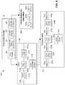
- FIG. 1Ais a relational diagram for a system 100 including a plant builder system 105 according to an embodiment.
- the system 100includes the plant builder system 105 , one or more databases 28 , and/or a process module simulator 110 .
- the one or more databases 28may include piping and instrumentation diagrams (P&IDs) 35 , sometimes referred to as a process and instrumentation diagrams 35 ; process modules 31 ; and/or control modules 29 .
- P&IDspiping and instrumentation diagrams
- the plant builder system 105(sometimes referred to as the plant builder 105 ) is a computer or group of computers configured to facilitate various stages of design and redesign for a plant 10 .
- the plant builder 105may be used to design a whole plant 10 or a part of a plant 10 , which may include various equipment components 130 .
- the plant builder 105may be useful for designing an expansion to an existing plant.
- the plant 10is a plant used for controlling any type of process.
- the plant 10may be a power plant, a chemical processing plant, an oil refinery, or any other process plant.
- the plant 10may include various equipment components 130 , such as field devices 14 , pipes 132 for moving material, tanks 134 for holding material, and other equipment components 136 .
- a control systemis utilized to monitor and control the process. This monitoring and control is accomplished by way of the field devices 14 , which typically include sensors for measuring various aspects of the process and/or actuators for manipulating various aspects of the process.
- field devices 14are typically communicatively connected to controllers (not shown) installed at the plant 10 that are responsible for controlling and/or monitoring various aspects of the process. Field devices 14 are described in more detail with reference to FIG. 1B .
- controllersnot shown
- Field devices 14are described in more detail with reference to FIG. 1B .
- the particular arrangement of the various equipment 130 in the plant 10is designed to achieve a specific goal. Thus, careful thought should go into the design of the plant 10 before it is constructed.
- the plant 10is described in more detail with reference to FIG. 1B .
- the plant builder system 105facilitates improved plant design.
- the plant builder 105enables the creation and use of three different types of entities: the P&IDs 35 , the equipment objects 39 , and the control modules 29 . These entities may be created and utilized in an integrated manner to provide enhanced plant design, plant simulation, and plant control.
- the P&IDs 35 , equipment objects 39 , and control modules 29may be stored at any suitable data store 28 , and may be stored together or independently.
- the P&IDs 35are diagrams showing relationships between equipment used in the plant 10 .
- Each P&ID 35comprises symbols 15 representing particular pieces of equipment 130 that are installed, or planned for potential installation, in the plant 10 .
- a P&ID 35can be thought of as a blueprint or roadmap for a particular area or unit of the plant 10 .
- a P&ID 35may depict a water cooling area for the plant 10 , and may include symbols 15 corresponding to the particular tanks 134 , pipes 132 , field devices 14 , and other equipment 136 to be included in the water cooling area.
- the P&IDs 35are designed and generated at the plant builder 105 , and may be displayed via a display at the plant builder 105 .
- Each equipment object 39represents a particular equipment component 130 installed (or planned for potential installation) in the plant 10 , and generally to a symbol 15 in a P&ID 35 .
- the equipment objects 39are modules, routines, and/or data structures that may be referenced and utilized by various devices within the plant 10 for plant design, simulation, and control. For each object 39 , these data structures may include attributes for the object 39 and for the equipment component 130 corresponding to the object 39 .
- each equipment object 39may include or reference: a particular identifier (“ID”) unique to the equipment component; a graphic element for the equipment component (for display on the P&ID and/or operator display); a material I/O element identifying other equipment objects the equipment object is linked to (and thus identifying other equipment components the underlying equipment component is connected to); a communication I/O element identifying a means (e.g., an I/O device address) for communicating with the underlying equipment component; simulation functionality for simulating the underlying equipment component; and/or device/equipment parameters corresponding to the represented equipment component 130 (e.g., a diameter or Reynolds number for a pipe).
- Example equipment objectsare shown in FIGS. 5 and 6 .
- One or more of the equipment objects 39may be organized as a collection or unit referred to as a process module 31 .
- each process module 31corresponds to a particular area or unit depicted in one of the P&IDs 35 , and may be used to simulate operation of that particular area or unit.
- Each equipment object 39may have multiple operation modes, such as “simulation mode” and “normal mode.” During normal mode or normal operation, an equipment object 39 may be referenced or otherwise utilized by the control system to communicate with corresponding equipment components 130 . For example, in normal operation, equipment objects 39 may: (i) forward control signals received from a control module 29 executing at a controller to an underlying field device 14 including an actuator (such as a pump or valve), and/or (ii) forward measurements received from an underlying field device 14 including a sensor (e.g., from a flow sensor or level sensor) to the appropriate control module 29 .
- an actuatorsuch as a pump or valve
- a sensore.g., from a flow sensor or level sensor
- the equipment objects 39may forward control signals received from a control module 30 to the process module simulator 110 , and may forward simulated measurements received from the simulator 110 (which may be simulating operation of the corresponding equipment component, such as a sensor) to the appropriate control module 29 .
- the simulator 110may be any computing device or system executing a simulation routine or routines configured to simulate operation of the equipment components 130 represented by the equipment objects 39 in the process module 31 .
- the simulator 110 and the plant builder system 105are distinct devices or platforms. In other embodiments, the simulator 110 and the plant builder system 105 are the same system or device. In some instances, the simulation routine may be an application, routine, or subroutine that is part of a larger suite of applications making up the plant builder system 105 .
- the simulator 110analyzes a simulated status of each of the equipment objects 39 and executes logic designed to simulate operation of the equipment components 130 according to the simulated status of the equipment objects 39 (e.g., according to the simulated measurements and inputs of the underlying equipment components 130 ). For example, when a simulated valve on a hot water line entering a tank is opened, the following downstream objects may be affected: a flow sensor on the hot water line; a temperature sensor for the liquid in the tank; and a level sensor for the liquid in the tank. The simulator 110 may simulate measurements for each of these sensors in response to the simulated valve opening. Depending on the embodiment, the simulator 110 may simulate operation of equipment represented by multiple process modules 31 by referencing the P&ID(s) 35 to determine relationships between the various process modules 31 .
- a “control module”is a set of instructions, executable by a processor (e.g., of a controller), for performing one or more operations to provide or perform on-line control of at least part of a process.
- the control modules 29may be saved to memory, e.g., as one or more routines, applications, software modules, or programs.
- the control modules 29may include any type of control module.
- the control modules 29may reference the equipment objects 39 to communicate with field devices 14 corresponding to the equipment objects 39 .
- Each of the control modules 29can be made up of function blocks 30 , wherein each function block 30 is a part or a subroutine of an overall control routine (e.g., embodied by one of the control modules 29 ).
- Function blocks 30which may be objects in an object oriented programming protocol, typically perform one of: (i) an input function, such as receiving an analog or discrete input signal associated with a transmitter, sensor, or other process parameter measurement device; (ii) a control function, such as that associated with a control routine that performs PID, fuzzy logic, etc.
- an output functionsuch as causing a controller to transmit an analog or discrete output signal to control operation of some actuator or device (such as a valve) to perform some physical function (e.g., opening or closing the valve) within the process plant 10 .
- some actuator or devicesuch as a valve
- some physical functione.g., opening or closing the valve
- Each control module 29may operate in conjunction with other control modules 29 and function blocks 30 (via communication links in the plant 10 ) to implement process control loops within the process plant 10 . While the Fieldbus protocol, DeltaV system protocol, and Ovation system protocol use control modules and function blocks designed and implemented in an object oriented programming protocol, the control modules 29 could be designed using any desired control programming scheme including, for example, sequential function block, ladder logic, etc.; and are not limited to being designed and implemented using function blocks or any other particular programming technique.
- FIG. 1Bis a block diagram of a distributed process control network located within a process plant 10 according to an embodiment.
- the process plant 10may be designed using the plant builder 105 (also shown in FIG. 1A ).
- the process plant 10uses a distributed process control system including one or more controllers 12 ; one or more field devices 14 ; one or more input/output (I/O) devices (sometimes referred to as I/O cards) 18 ; the plant builder system 105 ; one or more hosts or operator workstations 22 ; a network 24 ; and a database 28 .
- I/Oinput/output
- the network 24may be any suitable network, including wireless and/or wired links.
- the controllers 12 , workstation 22 , plant builder 105 , and database 28may be communicatively connected to the network 24 , and may each be considered a node of the network 24 when connected. While the controllers 12 , I/O cards 18 , and field devices 14 are typically located within and distributed throughout the sometimes harsh plant environment, the plant builder 105 , the operator workstation 22 , and the database 28 are often located in control rooms or other less harsh environments easily assessable by controller or maintenance personnel.
- Each of the controllers 12(which may be by way of example, the DeltaVTM controller sold by Emerson Process Management) stores and executes a controller application that implements a control strategy using any number of different, independently executed, control modules or blocks 29 .
- the one or more controllers 12may be communicatively connected to the network 24 , enabling the controllers 12 to communicate with other devices connected to the network 24 , such as the workstation 22 or computer 20 .
- the one or more controllers 12may be communicatively connected to the field devices 14 using any desired hardware and software, including but not limited to: standard 4-20 ma devices; the I/O device 18 ; and/or any smart communication protocol.
- Each I/O device 18may be any types of I/O device conforming to any desired communication or controller protocol.
- the I/O devices 18may be Fieldbus interfaces, Profibus interfaces, HART interfaces, WirelessHART interfaces, standard 4-20 ma interfaces, etc.
- the controller 12may implement a batch process or a continuous process using at least some of the field devices 14 .
- a field device 14is a device used to monitor and/or control the process.
- a field device 14generally is or includes an actuator, sensor, or some combination thereof.
- Each field device 14is communicatively coupled to a controller 12 (typically via an I/O device 18 , though a field device 14 may be directly coupled to a controller 12 in some embodiments).
- Some of the field devices 14may have an associated microprocessor that handles communications with the controller 12 and/or I/O devices 18 .
- an actuatorsuch as a pump or valve
- actuates in response to a control signal from a controller 12and a sensor outputs a measurement in response to detecting a physical phenomenon (e.g., a flow, temperature, or level of a material).
- the measurementis typically transmitted to a controller 12 via, for example, a transmitter coupled to the sensor.
- the field devices 14may be standard 4-20 ma devices; smart field devices, such as HART, Profibus, or FOUNDATIONTM Fieldbus field devices, (which include a processor and a memory); or any other desired type of device. Some of these field devices 14 , such as Fieldbus field devices, may store and execute modules, or sub-modules, such as the function blocks 30 , associated with the control strategy implemented in the controllers 12 . The function blocks 30 may be executed in conjunction with the execution of the control modules 29 within the controllers 12 to implement process control. In an embodiment, the function blocks 30 enable a field device 14 to function independent of a controller implementing a control routine.
- the plant 10may include one or more wireless field devices (not shown) communicatively connected via a wireless gateway to the network 24 .
- the workstation 22may be any computing device that operates as a user interface for operators or other users.
- the workstation 22may include a processor and memory (not shown), and may include a user interface routine 41 and other applications 43 .
- the user interface routine 41enables the workstation 22 to accept input via an input interface (such as a mouse, keyboard, touchscreen, etc.) and provide output at a display.
- the workstation 22may provide output (i.e., visual representations or graphics) representing aspects of the process associated with the plant 10 , allowing a user to monitor the process.
- the usermay also affect control of the process by providing input at the workstation 22 .
- the workstation 22may provide graphics representing, for example, a tank filling process.
- the usermay read a tank level measurement and decide that the tank needs to be filled. The user may then, for example, interact with an inlet valve graphic displayed at the workstation 22 and input a command causing the inlet valve to open.
- the database 28is a collection of data that may be utilized by devices in the plant 10 for various purposes.
- the database 28may be connected to the network 24 and may operate as a data historian that collects and stores parameter, status, and other data associated with the controllers 12 and field devices 14 within the plant 10 and/or as a configuration database that stores the current configuration of the process control system within the plant 10 as downloaded to and stored within the controllers 12 and field devices 14 .
- a server(not shown) may access the database 28 and provide other devices access to the stored data.
- the server and/or database 28may be hosted by a computer (not shown) similar to the workstation 22 or the computer 20 .
- the plant builder 105includes a computer 20 including a memory 34 and a processor 36 . While FIG. 1B depicts the plant builder 105 including a single computer 20 , it will be understood that the plant builder system 105 may include multiple computers in some embodiments.
- the plant builder system 105may accept input via an input interface (e.g., a keyboard, mouse, touchscreen, etc.) and may include or be coupled to a display screen 37 .
- the memory 34may store a plant builder routine 32 , as well as P&IDs 35 , equipment objects 39 , and control modules 29 .
- the memory 34may also store other applications and/or data structures not shown.
- the plant builder routine 32is an application, routine, or module executed by the processor 36 to enable the creation and use of the P&IDs 35 , equipment objects 39 , and control modules 29 .
- the plant builder routine 32may be a single application or a suite of applications, depending on the embodiment.
- the device executing the plant builder routine 32may be referred to as a “plant builder system,” “plant builder device,” or “plant builder tool.”
- the workstation 22may execute the plant builder routine 32 , and may be referred to as a “plant builder tool” or “plant builder device” when executing the plant builder routine 32 .
- the plant builder routine 32may be accessed by any authorized user (sometimes referred to herein as a configuration engineer or operator, although other types of users may exist) to view and provide functionality for the plant builder 105 .
- the plant builder routine 32may be implemented before other aspects of the plant 10 exist. That is, the plant builder routine 32 may be utilized to design the physical layout of the plant 10 and/or the communication scheme of the plant 10 .
- the particular communication links between the controllers 12 and the field devices 14may be designed via the plant builder routine 32 before the controllers 12 , the field devices 14 , and the other equipment components are installed in the plant 10 .
- the plant builder routine 32can provide display outputs to the display screen 37 or any other desired display screen or display device, including hand-held devices, laptops, other workstations, printers, etc.
- the plant builder routine 32(as well as other applications stored at the memory 34 ) may be broken up and executed on two or more computers or machines and may be configured to operate in conjunction with one another.
- the P&IDs 35 and equipment objects 39are illustrated as being stored at the computer 20 , they could be downloaded to and stored at any other computer associated with the process control plant 10 , including laptops, handheld devices, etc. In some instances, for example, the P&IDs 35 and/or process modules may be stored at the database 28 .
- control modules 29are illustrated as being stored and executed at the controllers 12 , the control modules 29 could be stored and/or executed by other computing devices within the plant 10 , particularly those connected to the network 24 .
- the control modules 29may be stored and/or executed by the workstation 22 in some instances.
- the control modules 29may be executed by a controller 12 or device that is wirelessly connected to the network 24 .
- FIG. 2is a flow chart of a prior art method 200 for designing a plant.
- the method 200begins with an engineer designing a P&ID using traditional stand-alone drafting software (block 205 ). The engineer then prints the P&ID (block 210 ). After all necessary P&IDs for the plant have been designed, the plant is constructed based on the P&IDs (block 215 ). That is, the tanks, pumps, valves, piping, etc. are installed according to the P&IDs. While the plant is under construction, a control engineer designs control strategies for controlling the constructed plant (block 222 ). Once the control strategies have been designed and the control system has been configured according to the designed control strategies, control of the plant is implemented using the designed control strategies (block 225 ).
- the plant and/or control strategiesmay be less optimal than originally planned, and may require redesign (block 230 ). If new control strategies require new equipment or a reconfigured plant layout, construction may be undertaken to implement the new design. This additional construction can cost millions of dollars in labor, equipment, and opportunity cost associated with delayed plant production.
- A.A Method 300 for Designing a Plant
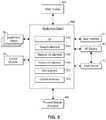
- FIG. 3is a flow chart of an example method 300 for designing a plant (e.g., the plant 10 shown in FIG. 1 ) according to an embodiment.
- the method 300enables iterative plant design. Unlike the prior art method 200 , for example, the method 300 facilitates extensive testing and simulation during the plant design process.
- the method 300may be utilized to test multiple P&ID designs and control strategies before a plant is constructed, enabling engineers to optimize design and control of the plant before the plant is constructed.
- the method 300begins with a user utilizing the plant builder 105 to design a P&ID 35 (shown in FIG. 1 ).
- a userwill design the P&ID 35 by placing various symbols (representing plant equipment components) in a configuration area provided as part of a user interface for the plant builder 105 . These symbols generally depict various types or categories of process equipment components, such as valves, tanks, pumps, etc.
- a usermay utilize a text entry box or dropdown menu to specify material connections for equipment represented by a symbol (e.g., to specify equipment physically upstream or downstream from the equipment represented by the symbol) and/or to specify communication connections for the equipment (e.g., to specify a means for communicating with equipment, such as a field device, represented by the symbol).
- material connections for equipment represented by a symbole.g., to specify equipment physically upstream or downstream from the equipment represented by the symbol
- communication connections for the equipmente.g., to specify a means for communicating with equipment, such as a field device, represented by the symbol.
- the plant builder 105may generate equipment objects 39 (shown in FIG. 1 ) corresponding to symbols in the P&ID 35 representing equipment components in the plant 10 , or representing equipment components for potential installation in the plant 10 .
- the plant builder 105may generate the equipment objects 39 as the user is designing the P&ID 35 .
- the plant builder 105may generate an equipment object 39 when a symbol (e.g., of a pump or valve) is dragged from a template library and dropped into a configuration area used for designing the P&ID 35 .
- the plant builder 105may generate equipment objects 39 after the user has finished designing the P&ID 35 (e.g., when the user saves the P&ID 35 to memory).
- the equipment objects 39may be stored to memory of the plant builder system 105 (shown in FIG. 1 ). In an embodiment, the equipment objects 39 may be stored to the database 28 (shown in FIG. 1 ).
- the plant builder 105may associate simulation functionality with the generated equipment objects 39 . More particularly, the equipment objects 39 may be linked in a manner equivalent to that shown in the P&ID 35 to create a process module 31 corresponding, for example, to an area or unit represented by the P&ID 35 .
- the created process module 31may be associated with a simulator routine that a user can configure via the plant builder 32 .
- the plant builder 105may link the equipment objects 39 based on links between symbols depicted in the P&ID 35 .
- the plant builder 105may provide an interface to enable a user to design and/or modify the simulation functionality provided by the process module simulator.
- Control strategiesmay be designed via the plant builder 105 .
- the plant builder 105may be utilized to design the control modules 29 shown in FIG. 1 .
- the control modules 29may be comprised of function blocks.
- the control modules 29may include input and/or output blocks that reference a field device 14 by referencing an equipment object 39 .
- an input blockmay reference an equipment object 39 representing a flow transmitter installed in the plant, enabling the input block to receive as an input a flow measurement from the flow transmitter.
- an output blockmay reference an equipment object 39 representing a valve installed in the plant, enabling the output block to transmit a control signal as an output, wherein the control signal causes the valve to close, open, or otherwise change position, for example.
- an engineermay specify various control functions that affect the particular value of control signals transmitted by output blocks. In some instances these control functions may be predefined to a certain extent. For example, an engineer may specify a “tank level” control function including one or more predefined routines for filling and/or draining a tank. Depending on the embodiment, the engineer may customize such predefined control functions for the particular application in question. For example, an engineer may customize the predefined “tank level” control function by inputting a maximum tank capacity for the particular tank that will be controlled by the “tank level” control function.
- the control strategiesare tested by simulating plant control using the simulated functionality associated with the generated equipment objects 39 .
- the control modules 29 and the previously described simulation routine associated with a process module 31may be executed.
- the simulation routinemaintains a simulation state for each of the equipment objects 39 , each of which may change in response to received control signals and changes in simulation states of other equipment objects 39 .
- control outputs generated by the control modules 29may be processed by the simulation routine rather than being sent to field devices 14
- control inputs received by the control modules 29may be values or signals generated by the simulation routine rather than measurements obtained by the field devices 14 .
- a control module 29may be configured to transmit a control signal to a valve object 39 .
- the control outputwould be forwarded to a valve corresponding to the valve object 39 (or to an I/O device associated with the valve).
- the control outputmay be handled by the simulation routine rather than being transmitted to the valve.
- the simulation routine associated with the process module 31may process the control output, simulating the valve actuating in response to the control output.
- the simulation routinemay update a simulated valve state, for example.
- the simulation routinemay also cause various other equipment objects 39 to respond to the simulated change to the valve position.
- the simulation routinemay include logic dictating that a tank fills when a simulated inlet valve opens.
- simulation outputs corresponding to process outputsmay then respond to the simulated tank filling.
- the simulation routinesimulates actual operation of the process, and responds to control signals received from the control modules 29 accordingly.
- the P&ID and/or control strategiescan be redesigned in light of the tests.
- the plantis constructed based on the designed (and potentially redesigned) P&IDs 35 .
- the method 300may be implemented, in whole or in part, by one or more systems or devices described herein.
- the method 300includes operations that may be performed by the plant builder 105 shown in FIG. 1 .
- a set of instructionse.g., executable by a processor
- for performing one or more operations of method 300may be saved to memory, e.g., as one or more routines, applications, software modules, or programs. While the operations described above are in a sequential order, one skilled in the art will appreciate that it may be possible for the operations to be performed in alternative sequences.
- FIG. 4is a relational diagram of a system 400 for designing a plant according to an embodiment.
- the system 400includes the plant builder routine 32 (also shown in FIG. 1A ), which may generate a P&ID 435 , a process module 431 , and/or a control module 429 .
- the plant builder routine 32may be implemented by the plant builder system 105 shown in FIGS. 1A and 1B .
- the plant builder routine 32may include various subroutines, such as a P&ID drafter subroutine 402 , an equipment object generator subroutine 404 , a process module simulator subroutine 406 , and/or a control module designer subroutine 408 . In some embodiments, one or more of these subroutines may be stand-alone applications that are part of a larger plant builder suite.
- the P&ID 435represents a particular example of one of the P&IDs 35 shown in FIGS. 1A and 1B .
- the process module 431 , the control module 429 , the equipment objects 439 , the symbols 415 , and the function blocks 430represent particular examples of the process module 31 , the control module 29 , the equipment objects 39 , the symbols 15 , and the function blocks 430 shown in FIGS. 1A and 1B .
- the P&ID drafter subroutine 402generates the P&ID 435 based on input from a user.
- the generated P&ID 435may include one or more symbols 415 a - i representing equipment components to be potentially installed in a plant (e.g., the equipment components 130 shown in FIG. 1A ).
- the P&ID 435may include pipe symbols 415 a - 415 d , valve symbols 415 f and 415 h , a tank symbol 415 g , and a level transmitter symbol 415 i .
- Example symbolsare described in more detail below with reference to FIG. 7 .
- the equipment object generator subroutine 404Based on the particular design of the generated P&ID 435 , the equipment object generator subroutine 404 generates one or more equipment objects 439 a - 439 i . Each of the generated objects 439 corresponds to a symbol 415 .
- the generator 404may generate each object 439 a - i as the respective symbol 415 a - i is created. Alternatively, the generator 404 may generate the objects 439 a - i after the symbols 415 a - i have been created, linked, and saved, for example.
- the equipment objects 439 a - imay each have associated simulation functionality, which may be provided by the process module simulator subroutine 406 .
- the simulator subroutine 406 subroutineis configured to simulate one or more equipment components, and may be implemented by the simulator 110 shown in FIG. 1A .
- each of the equipment objects 439 a - imay be linked to equipment components after the equipment components are installed in the plant.
- each of the equipment objects 439 a - imay include a communication I/O element that can be configured to reference the equipment component (e.g., field device) corresponding to the particular equipment object 439 a - i .
- the valve object 439 fmay include a communication I/O element that is configured (e.g., via the plant builder routine 32 ) to reference a valve installed in the plant. Accordingly, the object may be referenced or utilized to communicate with the corresponding valve (e.g., to send a control signal that causes the valve to open or close).
- the generator 404may automatically configure the generated objects 439 so that they are linked according to physical relationships depicted by the P&ID 435 . That is, the objects 439 may be linked according to the links between the symbols 415 in the P&ID 435 . As a result, one or more of the generated objects 439 may be configured to have one or more different material I/O connections.
- the valve object 439 fmay be configured to have two material I/O connections: the pipe object 439 a and the pipe object 439 b .
- a valvecorresponding to the object 4390 may control material flow from a first pipe (correspond to the object 439 a ) to a second pipe (corresponding to the object 439 b ), or vice versa, depending on the particular configuration.
- the process module simulator 406may rely on material I/O connections between objects 439 to simulate material flow throughout the equipment components represented by the process module 431 .
- the objects 439may be automatically generated and configured based on the particular design of the P&ID 435 .
- the P&ID 435includes a valve symbol 415 f linked to a pipe symbol 415 b , which is linked to a tank symbol 415 g .
- the valve object 439 f(corresponding to the valve symbol 415 f ) may be configured to be linked to the pipe object 439 b (corresponding to the pipe symbol 415 b ), which may be configured to be linked to the tank object 439 g (corresponding to the tank symbol 415 g ).
- a usermay manually define material I/O connections for a given equipment object 439 using, for example, a drop-down box.
- a usermay utilize the plant builder routine 32 to link a transmitter or sensor not shown in the P&ID 435 to an equipment object 439 .
- the plantmay have a flow transmitter that is associated with the valve represented by the valve object 439 f but that is not depicted in the P&ID 435 .
- a usermay link a flow transmitter to the valve object 439 f .
- a plantmay include equipment including a self-contained control system, such as a PLC.
- a plantmay include a boiler on a skid that is controlled by a PLC.
- the P&ID 435may depict equipment (e.g., the boiler) but not the corresponding self-contained control system (e.g., the PLC for the boiler). Accordingly, in such an example, a user may link a self-contained control system to equipment depicted in the P&ID 435 . In some embodiments, the plant builder 32 may respond to the user linking non-depicted equipment by automatically updating the P&ID 435 to depict the newly added equipment. Example equipment objects are described in more detail with reference to FIGS. 5 and 6 .
- the control module designer subroutine 408may generate the control module 429 based, for example, on user input.
- the control module 429is a control routine or set of routines configured to control one or more equipment components corresponding to the objects 439 .
- the control module 429may include one or more function blocks 430 .
- the control module 429includes an analog input (AI) block 430 a , a PID block 430 b , and an analog output (AO) block 430 c.
- the control module 429is configured to perform a tank filling operation for a tank represented by the tank object 439 g .
- the AI block 430 amay be configured to receive a control input from the level transmitter object 439 i .
- the object 439 imay receive a measurement from a level sensor installed at the tank, and may forward that measurement to the AI block 430 a .
- normal operation of the process using real equipment components installed in the plantonly occurs after the equipment components have been installed in the plant and linked to the appropriate equipment objects 439 referenced by the function blocks 430 .
- the level transmitter object 439 imay receive a simulated measurement generated by the simulator 406 , and may forward that simulated measurement to the AI block 430 a .
- the AI block 430 amay then pass the actual or simulated measurement to the PID block 430 b.
- the PID block 430 bmay execute logic to generate an output based on the actual or simulated measurement received from the AI block 430 a .
- the logic in the PID block 430 bmay be configured to generate an output to open an inlet valve (e.g., a valve corresponding to the valve object 439 f ) to fill the tank when the level measurement is low, and may generate an output to close the valve to stop filling the tank when the level measurement is high.
- the logicmay account for other variables in some instances, such as a desired setpoint for tank level.
- the generated outputmay be passed to the AO block 430 c , which may be configured to reference the valve object 439 f . Accordingly the AO block 430 c may pass the generated output to the valve object 439 f .
- the valve object 439 fWhen the valve object 439 f is operating in normal mode, it will pass the output signal to a valve installed in the plant.
- the valve object 439 fWhen the valve object 439 f is operating in simulation mode, it may pass the output signal to the simulator 406 .
- the simulator 406may then update a running simulation corresponding to the process module 431 based on the received output. For example, the simulator 406 may update a simulated valve state, which may affect simulated material flow through simulated pipes to which the valve is attached.
- an output signal to close a valvemay cause the simulator 406 to slow or halt simulated material flow through pipes connected to a simulated tank, causing a simulated tank fill operation to slow down or stop.
- the simulation functionality associated with the plant builder routine 32enables iterative plant design.
- a usercan design the P&ID 435 and control module 429 before installing the equipment components represented by the P&ID 435 .
- Thisenables the user to test physical layouts and control strategies for the particular unit represented by the P&ID 435 .
- design considerations regarding control strategieshave not significantly factored into plant design decisions. In many cases, this would lead to the construction of a plant or plant area where the physical layout of the plant did not facilitate optimal control.
- the plant builder routine 32remedies this plant design problem by enabling iterative process of designing, testing, and redesigning.
- FIG. 5is a block diagram of an example equipment object 500 that may be generated by the plant builder 105 shown in FIGS. 1A and 1B according to an embodiment.
- the equipment object 500represents a particular example of one of the equipment objects 39 shown in FIGS. 1A and 1B .
- Each of the following entitiesmay communicate with, utilize, or otherwise be associated with the equipment objects 500 : other equipment objects 39 (also shown in FIGS. 1A and 1B ); the P&ID drafter 402 (also shown in FIG. 4 ); the user interface routine 41 (also shown in FIG. 1B ); one or more of the I/O devices 18 (also shown in FIG. 1B ); one or more field devices 16 (also shown in FIGS. 1A and 1B ); the simulator routine 406 (also shown in FIG. 4 ); and one or more control modules 29 (also shown in FIGS. 1A and 1B ).
- the equipment object 500may include or reference various data.
- the equipment object 500may include at least one of: an ID 512 , a graphic element 514 , a material I/O element 516 , a communication I/O element 518 , and/or a simulation element 520 .
- the ID 512is a variable including an identifier or name unique to the equipment object 500 .
- the ID 512may sometimes be referred to as a tag.
- the ID 512may include an code or identifier unique to a particular equipment type.
- the ID 512may be “CV500,” wherein the letters “CV” indicate that the object 500 represents a control valve.
- the ID 512may also include a string of numbers or letters, which may be unique to the object 500 .
- the graphic element 514includes or references (e.g., via a pointer) a graphic representation of the equipment component corresponding to the object 500 .
- the graphic representationmay be generic in nature (e.g., a generic graphic of a valve), or may be more specific in nature (e.g., a detailed graphic of a particular valve). In some instances, the graphic may be the same graphic included in the P&ID that was used to generate the object 500 .
- the graphicmay be utilized by the user interface 41 to display a user interface for monitoring or controlling plant operation.
- the material I/O element 516includes or references other equipment objects 39 representing equipment components to which the equipment component represented by the object 500 is somehow physically connected.
- the material I/O element 516may reference equipment objects 39 representing inlet and outlet pipes connected to the tank or valve.
- the material I/O element 516may reference equipment objects 39 representing sensors or actuators attached or otherwise located in a close physical proximity relative to the underlying equipment component.
- the material I/O element 516may reference equipment objects 39 representing a pressure sensor that detects pressure within the tank, a level sensor that detects a liquid level within the tank, etc.
- the communication I/O element 518includes or references the equipment component corresponding to the object 500 .
- the communication I/O element 518may include an address for communicating with an appropriate field device 14 , or with an I/O device 18 coupled to the field device 14 .
- the object 500may be referenced (e.g., by a control module 29 implemented by controller) to communicate with a field device 14 (e.g., to send a control signal to the field device 14 , or to receive a measurement from the field device 14 ).
- the object 500may not reference a corresponding equipment component. For example, during the design stage, a corresponding equipment component might not yet exist, or might not yet be installed. Further, in some instances, the equipment component might not communicate with the object 500 .
- the object 500may represent a tank that has no communication capabilities.
- the object 500may not communicate with the tank itself, and the communication I/O element 518 may not reference anything (e.g., may include a null value).
- the tankmay have an associated level indicator, for example, which may be represented by another object 39 that references the level indicator and that can be utilized by a controller to receive measurements obtained by the level indicator.
- the simulation element 520includes or references simulation data and/or logic for simulating the equipment component corresponding to the object 500 .
- the simulation element 520may include or reference variables, objects, routines, etc. used to provide simulation functionality.
- the simulation element 520may specify variables that can be written to and read, for example, when the object 500 is operating in simulation mode. Rather than sending a control signal to the corresponding equipment component, for example, the value of the control signal may be written to a variable, which can then be utilized by a simulation routine that is simulating part of the process.
- the simulation element 520may reference a simulation routine (e.g., object, routine, subroutine, application, etc.) that is configured to simulate the corresponding equipment object.
- a simulation routinee.g., object, routine, subroutine, application, etc.
- Control signalsmay be sent to, and measurements may be received from, this simulation routine.
- a simulation routinemay represent a flow sensor, and may include logic for simulating a flow measurement based on other simulation factors (e.g., the status of other simulated equipment objects).
- a simulation routine referenced by the simulation element 520may provide a simulated flow measurement, which may be provided to a controller (e.g., to be processed by one or more control modules 29 implementing a control strategy).
- FIG. 6is a block diagram of the example equipment object 439 f (also shown in FIG. 4 ) that may be generated by the plant builder 105 shown in FIGS. 1A and 1B , according to an embodiment.
- the equipment object 439 frepresents a particular example of one of the equipment objects 39 shown in FIGS. 1A and 1B .
- the equipment object 439 fmay include one or more of: an ID 612 , a graphic element 614 , a material I/O element 616 , a communication I/O element 618 , and/or a simulation element 620 . These elements are similar in nature to the elements 512 - 518 described with reference to FIG. 5 .
- the equipment object 439 frepresents a particular valve installed, or planned for potential installation, in the plant.
- the ID element 612is a variable including a string 622 , “CV1,” that is unique to the object 439 f .
- Other process entitiese.g., controllers, control modules, simulation routines, etc.
- the particular value of the string 622(“CV1” in this case) may be specified by a user via the plant builder system 105 .
- the value of the string 622may be specified when creating the P&ID 435 (shown in FIG. 4 ), and the plant builder tool 105 may utilize this string value for the ID element 612 when generating the equipment object 439 f.
- the graphic element 614includes or references a graphic 624 .
- the graphic 624may be the same graphic included in the P&ID 435 , and may be utilized by the user interface 41 to provide a visualization of the equipment component corresponding to the object 439 f .
- the particular graphic 624 chosen for the graphic element 614may be chosen by a user via the plant builder system 105 .
- FIG. 7illustrates an interface for the plant builder 105 that may be utilized to choose a graphic from a library or template area.
- the material I/O element 616includes or references other equipment objects 39 representing equipment components to which the equipment component represented by the equipment object 439 f is connected.
- the material I/O element 626includes a field or variable for specifying at least one material input 626 and one material output 628 .
- the material input 626specifies an object name “P1,” which corresponds to the equipment object 439 a shown in FIG. 4 .
- the material output 628specifies an object name “P2,” which corresponds to the equipment object 439 b shown in FIG. 4 .
- the material input(s) 626 and output(s) 628may be populated by the plant builder 105 based on connections shown in the P&ID 435 .
- the communication I/O element 618includes or references the equipment component corresponding to the object 439 f .
- the communication I/O element 618includes fields or variables for specifying communication inputs 630 and communication outputs 632 .
- the communication outputs 632 for the object 439 finclude an address “AO Card 6, Address 02.” This represents a particular address for a particular I/O device 18 coupled to the valve represented by the object 439 f .
- a control module 29shown in FIGS. 1A and 1 B
- references the object 439 f to transmit a control signalfor example, the control signal may be transmitted to the particular address specified by the communication input 630 , enabling the controller implementing the control module 29 to open or close the valve, for example.
- a valvemay include a sensor, such as a flow sensor.
- the communication input 630may include an address for communicating with the I/O device coupled to that sensor (e.g., an analog input card coupled to the flow sensor).
- the simulation element 620includes or references simulation data and/or logic for simulating the valve corresponding to the object 439 f .
- the simulation element 620may include simulation input variables 634 and/or simulation output variables 636 . When in simulation mode, these variables may be written to and/or read.
- the control module 429 referencing the valve object 439 fmay transmit a control signal (e.g., a percentage indicating a valve position, such as 65% open). The value of this control signal may be written to the sim output 636 rather than transmitted to the communication output 632 .
- the simulation routine 638may then simulate a response of the process unit corresponding to the process module 431 .
- the simulation routine 638may simulate a tank (represented by the object 439 g ) filling when a control signal for opening the valve is received.
- the simulation routine 638may then report a simulated tank level measurement to the level transmitter object 439 i shown in FIG. 4 . Consequently, a process module 431 can be simulated, enabling a designer to test plant designs and control strategies before constructing the area or unit corresponding to the process module 431 .
- the simulation element 620may reference the simulator 638 without explicitly referencing the simulation variables 634 / 636 ; (ii) may reference the simulation variables 634 / 636 without explicitly referencing the simulator 638 ; or (iii) may reference both the simulation variables 634 / 636 and the simulator 638 .
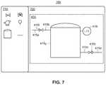
- FIG. 7depicts an example interface 700 for the plant builder 105 according to an embodiment.
- the plant builder routine 105provides the interface 700 (e.g., via the display screen 37 shown in FIG. 1 ) as part of the P&ID drafting routine or subroutine 402 shown in FIG. 4 .
- the example interface 700includes a library 710 and a configuration area 720 .
- the library 710includes a number of stencils or templates that may be dragged and dropped onto the configuration area 720 to create a P&ID 35 .
- the configuration area 720includes graphic symbols that have been arranged to create the P&ID 435 (also shown in FIG. 4 ).
- the template symbols included in the library 710represent generic symbols for certain categories or classes of equipment components.
- the library 710may include template symbols for tanks, valves, transmitters, pumps, pipes, etc. These template symbols may be dragged and dropped onto the configuration area 720 .
- a corresponding equipment object 439may be instantiated.
- valve symbol 415 fis dropped onto the configuration area 720
- the valve object 439 fmay be instantiated.
- a usermay then configure the instantiated object via, for example, a menu that can be activated by clicking on the symbol 415 f .
- the objects 439 a - iare not instantiated until the entire P&ID 435 is created.
- any reference to “one embodiment” or “an embodiment”means that a particular element, feature, structure, or characteristic described in connection with the embodiment is included in at least one embodiment.
- the appearances of the phrase “in one embodiment” in various places in the specificationare not necessarily all referring to the same embodiment.
- the terms “comprises,” “comprising,” “includes,” “including,” “has,” “having” or any other variation thereof,are intended to cover a non-exclusive inclusion.
- a process, method, article, or apparatus that comprises a list of elementsis not necessarily limited to only those elements but may include other elements not expressly listed or inherent to such process, method, article, or apparatus.
- “or”refers to an inclusive or and not to an exclusive or. For example, a condition A or B is satisfied by any one of the following: A is true (or present) and B is false (or not present), A is false (or not present) and B is true (or present), and both A and B are true (or present).
- references to a “memory” or “memory device”refer to a device including computer-readable media (“CRM”).
- CRMrefers to a medium or media accessible by the relevant computing system for placing, keeping, and/or retrieving information (e.g., data, computer-readable instructions, program modules, applications, routines, etc.).
- CCMrefers to media that is non-transitory in nature, and does not refer to disembodied transitory signals, such as radio waves.
- the CRM of any of the disclosed memory devicesmay include volatile and/or nonvolatile media, and removable and/or non-removable media.
- the CRMmay include, but is not limited to, RAM, ROM, EEPROM, flash memory, or other memory technology, CD-ROM, digital versatile disks (DVD) or other optical disk storage, magnetic cassettes, magnetic tape, magnetic disk storage or other magnetic storage devices, or any other medium which may be used to store information and which may be accessed by the computing system.
- One or more of the disclosed memory devicesmay be coupled to a processor via a memory interface.
- a memory interfaceis circuitry that manages the flow of data between the memory device and the bus of the computer system to which it is coupled.
- a “communication link” or “link”is a pathway or medium connecting two or more nodes (e.g., a device or system connected to the network).
- a linkmay be a physical link and/or a logical link.
- a physical linkis the interface and/or medium(s) over which information is transferred, and may be wired or wireless in nature. Examples of physicals links may include a cable with a conductor for transmission of electrical energy, a fiber optic connection for transmission of light, and/or a wireless electromagnetic signal that carries information via changes made to one or more properties of an electromagnetic wave(s).
- a logical link between two or more nodesrepresents an abstraction of the underlying physical links and/or intermediary nodes connecting the two or more nodes.
- two or more nodesmay be logically coupled via a logical link.
- the logical linkmay be established via any combination of physical links and intermediary nodes (e.g., routers, switches, or other networking equipment).
- a linkis sometimes referred to as a “communication channel.”
- the term “communication channel”(or just “channel”) generally refers to a particular frequency or frequency band.
- a carrier signal(or carrier wave) may be transmitted at the particular frequency or within the particular frequency band of the channel.
- multiple signalsmay be transmitted over a single band/channel.
- signalsmay sometimes be simultaneously transmitted over a single band/channel via different sub-bands or sub-channels.
- signalsmay sometimes be transmitted via the same band by allocating time slots over which respective transmitters and receivers use the band in question.
- Words such as “processing,” “computing,” “calculating,” “determining,” “presenting,” “displaying,” or the likemay refer to actions or processes of a machine (e.g., a computer) that manipulates or transforms data represented as physical (e.g., electronic, magnetic, or optical) quantities within one or more memories (e.g., volatile memory, non-volatile memory, or a combination thereof), registers, or other machine components that receive, store, transmit, or display information.
- a machinee.g., a computer
- memoriese.g., volatile memory, non-volatile memory, or a combination thereof
- registerse.g., volatile memory, non-volatile memory, or a combination thereof
Landscapes
- Engineering & Computer Science (AREA)
- Physics & Mathematics (AREA)
- General Physics & Mathematics (AREA)
- Theoretical Computer Science (AREA)
- Geometry (AREA)
- General Engineering & Computer Science (AREA)
- Computer Hardware Design (AREA)
- Evolutionary Computation (AREA)
- Manufacturing & Machinery (AREA)
- Quality & Reliability (AREA)
- Automation & Control Theory (AREA)
- Mathematical Analysis (AREA)
- Computational Mathematics (AREA)
- Pure & Applied Mathematics (AREA)
- Mathematical Optimization (AREA)
- Computer Networks & Wireless Communication (AREA)
- Civil Engineering (AREA)
- Architecture (AREA)
- Structural Engineering (AREA)
- Testing And Monitoring For Control Systems (AREA)
- Feedback Control In General (AREA)
- Programmable Controllers (AREA)
Abstract
Description
Claims (15)
Priority Applications (7)
| Application Number | Priority Date | Filing Date | Title |
|---|---|---|---|
| US15/221,096US10878140B2 (en) | 2016-07-27 | 2016-07-27 | Plant builder system with integrated simulation and control system configuration |
| CA2972540ACA2972540A1 (en) | 2016-07-27 | 2017-07-05 | Plant builder system with integrated simulation and control system configuration |
| PH12017000197APH12017000197A1 (en) | 2016-07-27 | 2017-07-05 | Plant builder system with integrated simulation and control system configuration |
| GB1711105.5AGB2554504B (en) | 2016-07-27 | 2017-07-10 | Plant builder system with integrated simulation and control system configuration |
| GB2202244.6AGB2600894B (en) | 2016-07-27 | 2017-07-10 | Plant builder system with integrated simulation and control system configuration |
| DE102017117038.3ADE102017117038A1 (en) | 2016-07-27 | 2017-07-27 | PLANT SYSTEM WITH INTEGRATED SIMULATION AND CONTROL SYSTEM CONFIGURATION |
| CN201710621668.1ACN107664988B (en) | 2016-07-27 | 2017-07-27 | Plant builder system with integrated simulation and control system configuration |
Applications Claiming Priority (1)
| Application Number | Priority Date | Filing Date | Title |
|---|---|---|---|
| US15/221,096US10878140B2 (en) | 2016-07-27 | 2016-07-27 | Plant builder system with integrated simulation and control system configuration |
Publications (2)
| Publication Number | Publication Date |
|---|---|
| US20180032651A1 US20180032651A1 (en) | 2018-02-01 |
| US10878140B2true US10878140B2 (en) | 2020-12-29 |
Family
ID=59676730
Family Applications (1)
| Application Number | Title | Priority Date | Filing Date |
|---|---|---|---|
| US15/221,096Active2038-05-04US10878140B2 (en) | 2016-07-27 | 2016-07-27 | Plant builder system with integrated simulation and control system configuration |
Country Status (6)
| Country | Link |
|---|---|
| US (1) | US10878140B2 (en) |
| CN (1) | CN107664988B (en) |
| CA (1) | CA2972540A1 (en) |
| DE (1) | DE102017117038A1 (en) |
| GB (2) | GB2600894B (en) |
| PH (1) | PH12017000197A1 (en) |
Cited By (4)
| Publication number | Priority date | Publication date | Assignee | Title |
|---|---|---|---|---|
| US20200310390A1 (en)* | 2019-03-28 | 2020-10-01 | Abb Schweiz Ag | Automatic process graphic generation |
| US11176290B1 (en) | 2020-12-21 | 2021-11-16 | Guangdong University Of Technology | Approximate physical simulation integrated debugging method and system based on digital twinning |
| US20220035347A1 (en)* | 2017-10-02 | 2022-02-03 | Fisher-Rosemount Systems, Inc. | Projects within a process control asset management system |
| US11418969B2 (en) | 2021-01-15 | 2022-08-16 | Fisher-Rosemount Systems, Inc. | Suggestive device connectivity planning |
Families Citing this family (13)
| Publication number | Priority date | Publication date | Assignee | Title |
|---|---|---|---|---|
| US10878140B2 (en)* | 2016-07-27 | 2020-12-29 | Emerson Process Management Power & Water Solutions, Inc. | Plant builder system with integrated simulation and control system configuration |
| EP3336631B1 (en)* | 2016-12-16 | 2021-06-16 | Siemens Aktiengesellschaft | Process control system and system planning tool |
| EP3726301B1 (en)* | 2017-12-15 | 2023-07-26 | Omron Corporation | Control device |
| JP6833112B2 (en)* | 2018-05-30 | 2021-02-24 | 三菱電機ビルテクノサービス株式会社 | Instrumentation design support device |
| US10649430B2 (en)* | 2018-06-26 | 2020-05-12 | Fisher-Rosemount Systems, Inc. | Method and apparatus for configuring access to multi-variable field devices signals |
| DE102019104987A1 (en)* | 2019-02-27 | 2020-08-27 | Phoenix Contact Gmbh & Co. Kg | Process for the system design of an electrical automation system |
| US11574090B2 (en)* | 2019-09-03 | 2023-02-07 | Yokogawa Electric Corporation | System and method for simulating field device in industrial plant |
| JP7276204B2 (en)* | 2020-03-06 | 2023-05-18 | 横河電機株式会社 | Information processing device, information processing method, and program |
| JP7331738B2 (en)* | 2020-03-06 | 2023-08-23 | 横河電機株式会社 | DRAWING MANAGEMENT DEVICE, DRAWING MANAGEMENT SYSTEM, DRAWING MANAGEMENT METHOD, AND PROGRAM |
| US20210294307A1 (en)* | 2020-03-19 | 2021-09-23 | Honeywell International Inc. | Assisted engineering design and development management system |
| US20220035359A1 (en)* | 2020-07-31 | 2022-02-03 | Palo Alto Research Center Incorporated | System and method for determining manufacturing plant topology and fault propagation information |
| WO2022118759A1 (en)* | 2020-12-03 | 2022-06-09 | 株式会社PlantStream | Program, method, and system |
| US20220253040A1 (en)* | 2021-02-10 | 2022-08-11 | Yokogawa Electric Corporation | Methods, systems and computer program products for generating and implementing engineering data within process control systems |
Citations (225)
| Publication number | Priority date | Publication date | Assignee | Title |
|---|---|---|---|---|
| USRE30280E (en) | 1973-09-21 | 1980-05-20 | Westinghouse Electric Corp. | Modular operating centers and methods of building same for use in electric power generating plants and other industrial and commercial plants, processes and systems |
| US4316952A (en) | 1980-05-12 | 1982-02-23 | Minnesota Mining And Manufacturing Company | Energy sensitive element having crosslinkable polyester |
| US4506324A (en) | 1982-03-08 | 1985-03-19 | The United States Of America As Represented By The Secretary Of The Navy | Simulator interface system |
| US4512747A (en) | 1982-01-13 | 1985-04-23 | Hitchens Max W | Material conveying system simulation and monitoring apparatus |
| JPS6075909A (en) | 1983-10-03 | 1985-04-30 | Toshiba Corp | valve monitoring device |
| US4546649A (en) | 1982-09-27 | 1985-10-15 | Kantor Frederick W | Instrumentation and control system and method for fluid transport and processing |
| US4613952A (en) | 1983-07-11 | 1986-09-23 | Foster Wheeler Energy Corporation | Simulator for an industrial plant |
| US4628435A (en) | 1983-03-09 | 1986-12-09 | Hitachi, Ltd. | Facilities control method |
| US4663704A (en) | 1984-12-03 | 1987-05-05 | Westinghouse Electric Corp. | Universal process control device and method for developing a process control loop program |
| US4736320A (en) | 1985-10-08 | 1988-04-05 | Foxboro Company | Computer language structure for process control applications, and translator therefor |
| JPH01120593A (en) | 1987-11-04 | 1989-05-12 | Toshiba Corp | Handy type operation training simulator |
| JPH01298389A (en) | 1988-05-27 | 1989-12-01 | Toshiba Corp | Plant simulator |
| US4885717A (en) | 1986-09-25 | 1989-12-05 | Tektronix, Inc. | System for graphically representing operation of object-oriented programs |
| US4972328A (en) | 1988-12-16 | 1990-11-20 | Bull Hn Information Systems Inc. | Interactive knowledge base end user interface driven maintenance and acquisition system |
| US4977529A (en) | 1973-02-23 | 1990-12-11 | Westinghouse Electric Corp. | Training simulator for a nuclear power plant |
| JPH02310602A (en) | 1989-05-26 | 1990-12-26 | Hitachi Ltd | Model synthesis type flow analysis system |
| US5014208A (en) | 1989-01-23 | 1991-05-07 | Siemens Corporate Research, Inc. | Workcell controller employing entity-server model for physical objects and logical abstractions |
| US5021947A (en) | 1986-03-31 | 1991-06-04 | Hughes Aircraft Company | Data-flow multiprocessor architecture with three dimensional multistage interconnection network for efficient signal and data processing |
| US5041964A (en) | 1989-06-12 | 1991-08-20 | Grid Systems Corporation | Low-power, standby mode computer |
| US5051898A (en) | 1988-06-13 | 1991-09-24 | Eda Systems, Inc. | Method for specifying and controlling the invocation of a computer program |
| JPH03257509A (en) | 1990-03-08 | 1991-11-18 | Hitachi Ltd | Plant operation control device and its display method |
| US5079731A (en) | 1989-10-17 | 1992-01-07 | Alcon Laboratories, Inc. | Method and apparatus for process control validation |
| US5092449A (en) | 1989-12-08 | 1992-03-03 | Liberty Glass Co. | Article transfer apparatus |
| US5097412A (en) | 1987-04-24 | 1992-03-17 | Hitachi, Ltd. | Method for simulating the operation of programs in a distributed processing system |
| US5119468A (en) | 1989-02-28 | 1992-06-02 | E. I. Du Pont De Nemours And Company | Apparatus and method for controlling a process using a trained parallel distributed processing network |
| US5159685A (en) | 1989-12-06 | 1992-10-27 | Racal Data Communications Inc. | Expert system for communications network |
| US5168441A (en) | 1990-05-30 | 1992-12-01 | Allen-Bradley Company, Inc. | Methods for set up and programming of machine and process controllers |
| JPH0554277A (en) | 1991-08-23 | 1993-03-05 | Mitsubishi Electric Corp | Plant monitoring equipment |
| US5218709A (en) | 1989-12-28 | 1993-06-08 | The United States Of America As Represented By The Administrator Of The National Aeronautics And Space Administration | Special purpose parallel computer architecture for real-time control and simulation in robotic applications |
| US5241296A (en) | 1991-03-04 | 1993-08-31 | Information Service International Dentsu, Ltd. | Plant activation tracking and display apparatus |
| US5268834A (en) | 1991-06-24 | 1993-12-07 | Massachusetts Institute Of Technology | Stable adaptive neural network controller |
| JPH0626093A (en) | 1992-07-09 | 1994-02-01 | Meidensha Corp | Rain water pump operation supporting system |
| US5321829A (en) | 1990-07-20 | 1994-06-14 | Icom, Inc. | Graphical interfaces for monitoring ladder logic programs |
| US5347446A (en) | 1991-02-08 | 1994-09-13 | Kabushiki Kaisha Toshiba | Model predictive control apparatus |
| US5347466A (en) | 1991-07-15 | 1994-09-13 | The Board Of Trustees Of The University Of Arkansas | Method and apparatus for power plant simulation and optimization |
| US5361198A (en) | 1992-04-03 | 1994-11-01 | Combustion Engineering, Inc. | Compact work station control room |
| JPH0736538A (en) | 1993-07-16 | 1995-02-07 | Nippon Metsukusu Kk | Fault diagnostic method for equipment representable its operating state shown in continuous value |
| US5428555A (en) | 1993-04-20 | 1995-06-27 | Praxair, Inc. | Facility and gas management system |
| JPH07248941A (en) | 1994-03-08 | 1995-09-26 | Nec Corp | Debug support device |
| US5485620A (en) | 1994-02-25 | 1996-01-16 | Automation System And Products, Inc. | Integrated control system for industrial automation applications |
| US5485600A (en) | 1992-11-09 | 1996-01-16 | Virtual Prototypes, Inc. | Computer modelling system and method for specifying the behavior of graphical operator interfaces |
| US5491625A (en) | 1993-12-23 | 1996-02-13 | The Dow Chemical Company | Information display system for actively redundant computerized process control |
| US5509116A (en) | 1990-03-30 | 1996-04-16 | International Business Machines Corporation | Graphical user interface management system |
| US5530643A (en) | 1993-08-24 | 1996-06-25 | Allen-Bradley Company, Inc. | Method of programming industrial controllers with highly distributed processing |
| US5546301A (en) | 1994-07-19 | 1996-08-13 | Honeywell Inc. | Advanced equipment control system |
| US5555385A (en) | 1993-10-27 | 1996-09-10 | International Business Machines Corporation | Allocation of address spaces within virtual machine compute system |
| US5576946A (en) | 1993-09-30 | 1996-11-19 | Fluid Air, Inc. | Icon based process design and control system |
| JPH08314760A (en) | 1995-05-23 | 1996-11-29 | Hitachi Ltd | Program development support device |
| US5594858A (en) | 1993-07-29 | 1997-01-14 | Fisher-Rosemount Systems, Inc. | Uniform control template generating system and method for process control programming |
| US5603018A (en) | 1991-07-15 | 1997-02-11 | Mitsubishi Denki Kabushiki Kaisha | Program developing system allowing a specification definition to be represented by a plurality of different graphical, non-procedural representation formats |
| US5611059A (en) | 1994-09-02 | 1997-03-11 | Square D Company | Prelinked parameter configuration, automatic graphical linking, and distributed database configuration for devices within an automated monitoring/control system |
| JPH09134213A (en) | 1995-11-08 | 1997-05-20 | Mitsubishi Heavy Ind Ltd | Plant state visualization system |
| US5631825A (en) | 1993-09-29 | 1997-05-20 | Dow Benelux N.V. | Operator station for manufacturing process control system |
| WO1997038362A1 (en) | 1996-04-04 | 1997-10-16 | Westinghouse Electric Corporation | A stimulated simulator for a distributed process control system |
| JPH09288512A (en) | 1996-04-22 | 1997-11-04 | Toshiba Corp | Plant status visualization system |
| WO1997045778A1 (en) | 1996-05-28 | 1997-12-04 | Fisher-Rosemount Systems, Inc. | Real-time process control simulation method and apparatus |
| EP0813129A2 (en) | 1996-06-14 | 1997-12-17 | The Foxboro Company | Keypad annunciator graphical user interface |
| JPH09330013A (en) | 1996-06-11 | 1997-12-22 | Kubota Corp | Simulation system for plant operation training |
| US5732192A (en) | 1994-11-30 | 1998-03-24 | The United States Of America As Represented By The Administrator Of The National Aeronautics And Space Administration | Global qualitative flow-path modeling for local state determination in simulation and analysis |
| US5768119A (en) | 1996-04-12 | 1998-06-16 | Fisher-Rosemount Systems, Inc. | Process control system including alarm priority adjustment |
| US5796602A (en) | 1996-02-06 | 1998-08-18 | Fisher-Rosemount Systems, Inc. | Method and apparatus using a device description for a conventional device |
| US5801942A (en) | 1996-04-12 | 1998-09-01 | Fisher-Rosemount Systems, Inc. | Process control system user interface including selection of multiple control languages |
| US5806053A (en) | 1995-08-30 | 1998-09-08 | Siemens Aktiengesellschaft | Method for training a neural network with the non-deterministic behavior of a technical system |
| US5812394A (en) | 1995-07-21 | 1998-09-22 | Control Systems International | Object-oriented computer program, system, and method for developing control schemes for facilities |
| US5818736A (en) | 1996-10-01 | 1998-10-06 | Honeywell Inc. | System and method for simulating signal flow through a logic block pattern of a real time process control system |
| US5821934A (en) | 1986-04-14 | 1998-10-13 | National Instruments Corporation | Method and apparatus for providing stricter data type capabilities in a graphical data flow diagram |
| US5828851A (en) | 1996-04-12 | 1998-10-27 | Fisher-Rosemount Systems, Inc. | Process control system using standard protocol control of standard devices and nonstandard devices |
| EP0875826A1 (en) | 1997-04-21 | 1998-11-04 | Kabushiki Kaisha Toshiba | Monitoring and control system and information recording medium used in the same |
| US5838561A (en) | 1996-04-29 | 1998-11-17 | Pulp And Paper Research Institute Of Canada | Automatic control loop monitoring and diagnostics |
| US5838563A (en) | 1996-04-12 | 1998-11-17 | Fisher-Rosemont Systems, Inc. | System for configuring a process control environment |
| US5862052A (en) | 1996-04-12 | 1999-01-19 | Fisher-Rosemount Systems, Inc. | Process control system using a control strategy implemented in a layered hierarchy of control modules |
| DE19740972C1 (en) | 1997-09-17 | 1999-03-11 | Siemens Ag | Modelling and simulating for technical plant |
| US5889530A (en) | 1996-03-14 | 1999-03-30 | Tandem Computers, Inc. | Method and apparatus for dynamically presenting graphical representation of instrumentation |
| US5892939A (en) | 1996-10-07 | 1999-04-06 | Honeywell Inc. | Emulator for visual display object files and method of operation thereof |
| US5898860A (en) | 1996-10-01 | 1999-04-27 | Leibold; William Steven | System and method for automatically generating a control drawing for a real-time process control system |
| US5909916A (en) | 1997-09-17 | 1999-06-08 | General Motors Corporation | Method of making a catalytic converter |
| US5940294A (en) | 1996-04-12 | 1999-08-17 | Fisher-Rosemont Systems, Inc. | System for assisting configuring a process control environment |
| US5950006A (en) | 1997-11-05 | 1999-09-07 | Control Technology Corporation | Object-oriented programmable controller |
| US5970430A (en) | 1996-10-04 | 1999-10-19 | Fisher Controls International, Inc. | Local device and process diagnostics in a process control network having distributed control functions |
| US5980078A (en) | 1997-02-14 | 1999-11-09 | Fisher-Rosemount Systems, Inc. | Process control system including automatic sensing and automatic configuration of devices |
| US5983016A (en) | 1996-11-12 | 1999-11-09 | International Business Machines Corporation | Execution engine in an object modeling tool |
| US5995916A (en) | 1996-04-12 | 1999-11-30 | Fisher-Rosemount Systems, Inc. | Process control system for monitoring and displaying diagnostic information of multiple distributed devices |
| US5995753A (en) | 1996-11-14 | 1999-11-30 | Alcatel Usa Sourcing, L.P. | System and method of constructing dynamic objects for an application program |
| US6003037A (en) | 1995-11-14 | 1999-12-14 | Progress Software Corporation | Smart objects for development of object oriented software |
| US6023644A (en) | 1996-09-12 | 2000-02-08 | Kinsman; Guy W. | Monitoring system for electrostatic powder painting industry |
| JP2000050531A (en) | 1998-07-24 | 2000-02-18 | Fuji Electric Co Ltd | How to display power system information |
| JP2000047860A (en) | 1998-05-28 | 2000-02-18 | Mitsubishi Electric Corp | Program design equipment |
| US6032208A (en) | 1996-04-12 | 2000-02-29 | Fisher-Rosemount Systems, Inc. | Process control system for versatile control of multiple process devices of various device types |
| US6041171A (en) | 1997-08-11 | 2000-03-21 | Jervis B. Webb Company | Method and apparatus for modeling material handling systems |
| JP2000148226A (en) | 1998-10-29 | 2000-05-26 | Endress & Hauser Gmbh & Co | Apparatus for use in an industrial process and a plant with a plurality of such apparatuses and a method for simulating the operation of such a plant |
| US6069629A (en) | 1997-11-25 | 2000-05-30 | Entelos, Inc. | Method of providing access to object parameters within a simulation model |
| US6098116A (en) | 1996-04-12 | 2000-08-01 | Fisher-Rosemont Systems, Inc. | Process control system including a method and apparatus for automatically sensing the connection of devices to a network |
| JP2000242323A (en) | 1999-02-24 | 2000-09-08 | Hitachi Ltd | Plant operation guidance system |
| JP2000243323A (en) | 1999-02-22 | 2000-09-08 | Canon Inc | Image forming apparatus and manufacturing method thereof |
| GB2348020A (en) | 1999-03-12 | 2000-09-20 | Fisher Rosemount Systems Inc | Process control system with generic control routine which creates instantiated control programs |
| JP2000266213A (en) | 1999-03-12 | 2000-09-26 | Toshiba Corp | Inching operation type electric valve control device |
| JP2000292584A (en) | 1999-04-08 | 2000-10-20 | Toshiba Corp | Nuclear instrumentation design support system |
| US6138174A (en) | 1997-11-24 | 2000-10-24 | Rockwell Technologies, Llc | Industrial control system providing remote execution of graphical utility programs |
| US6146143A (en) | 1997-04-10 | 2000-11-14 | Faac Incorporated | Dynamically controlled vehicle simulation system, and methods of constructing and utilizing same |
| US6157864A (en) | 1998-05-08 | 2000-12-05 | Rockwell Technologies, Llc | System, method and article of manufacture for displaying an animated, realtime updated control sequence chart |
| US6161051A (en) | 1998-05-08 | 2000-12-12 | Rockwell Technologies, Llc | System, method and article of manufacture for utilizing external models for enterprise wide control |
| JP2000346299A (en) | 1999-06-08 | 2000-12-15 | Yamatake Sangyo Systems Co Ltd | Plant control device |
| US6167316A (en) | 1998-04-03 | 2000-12-26 | Johnson Controls Technology Co. | Distributed object-oriented building automation system with reliable asynchronous communication |
| US6173438B1 (en) | 1997-08-18 | 2001-01-09 | National Instruments Corporation | Embedded graphical programming system |
| US6178393B1 (en) | 1995-08-23 | 2001-01-23 | William A. Irvin | Pump station control system and method |
| US6195591B1 (en) | 1996-04-12 | 2001-02-27 | Fisher-Rosemount Systems, Inc. | Process control system using a process control strategy distributed among multiple control elements |
| US6201996B1 (en) | 1998-05-29 | 2001-03-13 | Control Technology Corporationa | Object-oriented programmable industrial controller with distributed interface architecture |
| US6298454B1 (en) | 1999-02-22 | 2001-10-02 | Fisher-Rosemount Systems, Inc. | Diagnostics in a process control system |
| JP2001273006A (en) | 2000-03-27 | 2001-10-05 | Osaka Gas Co Ltd | Energy plant operation evaluation system |
| US20010039462A1 (en) | 2000-04-03 | 2001-11-08 | Rafael Mendez | System and method for predicting software models using material-centric process instrumentation |
| US6366272B1 (en) | 1995-12-01 | 2002-04-02 | Immersion Corporation | Providing interactions between simulated objects using force feedback |
| EP1204033A2 (en) | 2000-11-02 | 2002-05-08 | Hitachi, Ltd. | Database integration management method and apparatus and processing program, medium therefor |
| JP2002140114A (en) | 2000-11-02 | 2002-05-17 | Yokogawa Electric Corp | Operation monitoring display |
| US6415418B1 (en) | 1999-08-27 | 2002-07-02 | Honeywell Inc. | System and method for disseminating functional blocks to an on-line redundant controller |
| JP2002189503A (en) | 2000-12-20 | 2002-07-05 | Kawasaki Heavy Ind Ltd | Control device with simulation function |
| JP2002215221A (en) | 2001-01-17 | 2002-07-31 | Toshiba Corp | Monitoring and control equipment |
| GB2371884A (en) | 2000-10-12 | 2002-08-07 | Abb Ab | Queries in an object-oriented computer system |
| US20020111783A1 (en) | 2001-01-19 | 2002-08-15 | Kodosky Jeffrey L. | Simulation, measurement and/or control system and method with coordinated timing |
| US6442515B1 (en) | 1998-10-26 | 2002-08-27 | Invensys Systems, Inc. | Process model generation independent of application mode |
| US6442512B1 (en) | 1998-10-26 | 2002-08-27 | Invensys Systems, Inc. | Interactive process modeling system |
| US6445963B1 (en) | 1999-10-04 | 2002-09-03 | Fisher Rosemount Systems, Inc. | Integrated advanced control blocks in process control systems |
| US6449624B1 (en) | 1999-10-18 | 2002-09-10 | Fisher-Rosemount Systems, Inc. | Version control and audit trail in a process control system |
| JP2002258936A (en) | 2001-03-06 | 2002-09-13 | Mitsubishi Electric Corp | Plant monitoring and control system engineering tool |
| JP2002303564A (en) | 2001-04-05 | 2002-10-18 | Hitachi Ltd | Valve management system |
| US6477435B1 (en) | 1999-09-24 | 2002-11-05 | Rockwell Software Inc. | Automated programming system for industrial control using area-model |
| US20020198668A1 (en)* | 2001-04-24 | 2002-12-26 | Lull John M. | System and method for a mass flow controller |
| US6505519B2 (en) | 2000-03-23 | 2003-01-14 | Invensys Systems, Inc. | Correcting for two-phase flow in a digital flowmeter |
| US6510351B1 (en) | 1999-03-15 | 2003-01-21 | Fisher-Rosemount Systems, Inc. | Modifier function blocks in a process control system |
| US6515683B1 (en) | 1999-06-22 | 2003-02-04 | Siemens Energy And Automation | Autoconfiguring graphic interface for controllers having dynamic database structures |
| JP2003034629A (en) | 2001-07-18 | 2003-02-07 | National Institute Of Advanced Industrial & Technology | Bleaching materials and bleaching systems for discolored teeth |
| US6522934B1 (en) | 1999-07-02 | 2003-02-18 | Fisher-Rosemount Systems, Inc. | Dynamic unit selection in a process control system |
| EP1284446A1 (en) | 2001-08-13 | 2003-02-19 | Rockwell Software Inc. | Industrial controller automation interface |
| US6546297B1 (en) | 1998-11-03 | 2003-04-08 | Robertshaw Controls Company | Distributed life cycle development tool for controls |
| US6577908B1 (en) | 2000-06-20 | 2003-06-10 | Fisher Rosemount Systems, Inc | Adaptive feedback/feedforward PID controller |
| US6587108B1 (en) | 1999-07-01 | 2003-07-01 | Honeywell Inc. | Multivariable process matrix display and methods regarding same |
| US6618630B1 (en) | 1999-07-08 | 2003-09-09 | Fisher-Rosemount Systems, Inc. | User interface that integrates a process control configuration system and a field device management system |
| US6618745B2 (en) | 1999-09-10 | 2003-09-09 | Fisher Rosemount Systems, Inc. | Linking device in a process control system that allows the formation of a control loop having function blocks in a controller and in field devices |
| US20030188830A1 (en) | 2002-04-08 | 2003-10-09 | Applied Materials, Inc. | Substrate support having barrier capable of detecting fluid leakage |
| US6633782B1 (en) | 1999-02-22 | 2003-10-14 | Fisher-Rosemount Systems, Inc. | Diagnostic expert in a process control system |
| US20030200062A1 (en) | 2002-04-22 | 2003-10-23 | Autodesk, Inc. | Adaptable multi-representation building systems part |
| US6647315B1 (en) | 2000-09-29 | 2003-11-11 | Fisher-Rosemount Systems, Inc. | Use of remote soft phases in a process control system |
| US6684385B1 (en) | 2000-01-14 | 2004-01-27 | Softwire Technology, Llc | Program object for use in generating application programs |
| US6687698B1 (en) | 1999-10-18 | 2004-02-03 | Fisher Rosemount Systems, Inc. | Accessing and updating a configuration database from distributed physical locations within a process control system |
| US20040032433A1 (en) | 2002-08-13 | 2004-02-19 | Kodosky Jeffrey L. | Representing unspecified information in a measurement system |
| US6704737B1 (en) | 1999-10-18 | 2004-03-09 | Fisher-Rosemount Systems, Inc. | Accessing and updating a configuration database from distributed physical locations within a process control system |
| US6711629B1 (en) | 1999-10-18 | 2004-03-23 | Fisher-Rosemount Systems, Inc. | Transparent support of remote I/O in a process control system |
| US20040078182A1 (en) | 2002-10-21 | 2004-04-22 | Mark Nixon | Simulation system for multi-node process control systems |
| US6754885B1 (en) | 1999-05-17 | 2004-06-22 | Invensys Systems, Inc. | Methods and apparatus for controlling object appearance in a process control configuration system |
| JP2004199656A (en) | 2002-10-22 | 2004-07-15 | Fisher Rosemount Syst Inc | Process control system element |
| US6795798B2 (en) | 2001-03-01 | 2004-09-21 | Fisher-Rosemount Systems, Inc. | Remote analysis of process control plant data |
| US6804636B2 (en) | 2000-08-21 | 2004-10-12 | Fujitsu Limited | Control program development support apparatus |
| US20040249483A1 (en) | 2003-06-05 | 2004-12-09 | Wojsznis Wilhelm K. | Multiple-input/multiple-output control blocks with non-linear predictive capabilities |
| US20050062677A1 (en) | 1999-02-12 | 2005-03-24 | Nixon Mark J. | Portable computer in a process control environment |
| US20050158701A1 (en) | 2003-11-26 | 2005-07-21 | West Larry E. | Integrated bio-reactor monitor and control system |
| US20050164684A1 (en) | 1999-02-12 | 2005-07-28 | Fisher-Rosemount Systems, Inc. | Wireless handheld communicator in a process control environment |
| US20050187717A1 (en) | 2004-02-20 | 2005-08-25 | The Mathworks, Inc. | Method and apparatus for integrated modeling, simulation and analysis of chemical and biochemical reactions |
| US20050197786A1 (en) | 2001-01-23 | 2005-09-08 | Conformia Software, Inc. | System and method for managing the development and manufacturing of a pharmaceutical drug |
| US6957110B2 (en)* | 2001-06-19 | 2005-10-18 | Eutech Cybernetics | Method and apparatus for automatically generating a SCADA system |
| US20050257195A1 (en) | 2004-05-14 | 2005-11-17 | National Instruments Corporation | Creating and executing a graphical program with first model of computation that includes a structure supporting second model of computation |
| US20060073013A1 (en) | 2004-09-10 | 2006-04-06 | Emigholz Kenneth F | Application of abnormal event detection technology to fluidized catalytic cracking unit |
| US20060106477A1 (en) | 2002-07-09 | 2006-05-18 | Kazuo Miyashita | Production plan creation system, method, and program |
| US7050083B2 (en) | 2002-08-23 | 2006-05-23 | Samsung Electronics Co., Ltd. | Sub-scanning interval adjusting apparatus for multi-beam laser scanning unit |
| US7050863B2 (en) | 2002-09-11 | 2006-05-23 | Fisher-Rosemount Systems, Inc. | Integrated model predictive control and optimization within a process control system |
| US7076740B2 (en) | 2002-01-15 | 2006-07-11 | National Instruments Corporation | System and method for performing rapid control prototyping using a plurality of graphical programs that share a single graphical user interface |
| US7089530B1 (en) | 1999-05-17 | 2006-08-08 | Invensys Systems, Inc. | Process control configuration system with connection validation and configuration |
| US7096465B1 (en) | 1999-05-17 | 2006-08-22 | Invensys Systems, Inc. | Process control configuration system with parameterized objects |
| JP2006244072A (en) | 2005-03-02 | 2006-09-14 | Jfe Engineering Kk | Plant state simulation method and system |
| US7110835B2 (en) | 2002-10-22 | 2006-09-19 | Fisher-Rosemount Systems, Inc. | Integration of graphic display elements, process modules and control modules in process plants |
| US7113834B2 (en) | 2000-06-20 | 2006-09-26 | Fisher-Rosemount Systems, Inc. | State based adaptive feedback feedforward PID controller |
| US20060259163A1 (en) | 2000-03-10 | 2006-11-16 | Smiths Detection Inc. | Temporary expanding integrated monitoring network |
| US20070059838A1 (en) | 2005-09-13 | 2007-03-15 | Pavilion Technologies, Inc. | Dynamic constrained optimization of chemical manufacturing |
| US20070078529A1 (en) | 2005-09-30 | 2007-04-05 | Fisher-Rosemount Systems, Inc. | On-line adaptive model predictive control in a process control system |
| US20070129917A1 (en) | 2002-10-22 | 2007-06-07 | Fisher-Rosemount Systems, Inc. | Updating and Utilizing Dynamic Process Simulation in an Operating Process Environment |
| US20070132779A1 (en)* | 2004-05-04 | 2007-06-14 | Stephen Gilbert | Graphic element with multiple visualizations in a process environment |
| WO2007067645A2 (en) | 2005-12-05 | 2007-06-14 | Fisher-Rosemount Systems, Inc. | Multi-objective predictive process optimization with concurrent process simulation |
| US7266476B2 (en) | 1999-09-30 | 2007-09-04 | Rockwell Automation Technologies, Inc. | Simulation method and apparatus for use in enterprise controls |
| US7275235B2 (en)* | 2001-08-29 | 2007-09-25 | Molinari Alfred A | Graphical application development system for test, measurement and process control applications |
| US7317959B2 (en) | 2001-12-12 | 2008-01-08 | Siemens Aktiengesellschaft | System and method for modeling and/or executing software applications, especially MES applications |
| US20080027704A1 (en) | 2006-07-28 | 2008-01-31 | Emerson Process Management Power & Water Solutions, Inc. | Real-time synchronized control and simulation within a process plant |
| US7395122B2 (en) | 2001-07-13 | 2008-07-01 | Siemens Aktiengesellschaft | Data capture for electronically delivered automation services |
| US20080288089A1 (en) | 2007-05-15 | 2008-11-20 | Fisher-Rosemount Systems, Inc. | Methods and systems for batch processing and execution in a process system |
| US7502656B2 (en) | 1996-08-20 | 2009-03-10 | Invensys Systems, Inc. | Methods and apparatus for remote process control |
| US7555471B2 (en) | 2006-01-27 | 2009-06-30 | Google Inc. | Data object visualization |
| US7557702B2 (en) | 1999-02-22 | 2009-07-07 | Evren Eryurek | Integrated alert generation in a process plant |
| US7565215B2 (en) | 2003-12-18 | 2009-07-21 | Curtiss-Wright Flow Control Corporation | System and method for protection system design support |
| US20090210814A1 (en) | 2007-10-01 | 2009-08-20 | Agrusa Russell L | Visualization of process control data |
| US20090222752A1 (en) | 2008-03-03 | 2009-09-03 | Brian Alexander Wall | Industrial automation visualization object having integrated hmi and control components |
| US7593780B2 (en) | 2004-11-03 | 2009-09-22 | Rockwell Automation Technologies, Inc. | HMI reconfiguration method and system |
| US20090287321A1 (en) | 2003-02-18 | 2009-11-19 | Fisher-Rosemount Systems, Inc. | Configuration system using security objects in a process plant |
| US20090292514A1 (en)* | 2008-02-15 | 2009-11-26 | Invensys Systems, Inc. | System And Method For Autogenerating Simulations For Process Control System Checkout And Operator Training |
| US7627860B2 (en)* | 2001-08-14 | 2009-12-01 | National Instruments Corporation | Graphically deployment of a program with automatic conversion of program type |
| US7743362B2 (en) | 1998-02-17 | 2010-06-22 | National Instruments Corporation | Automatic generation of application domain specific graphical programs |
| US20100251255A1 (en)* | 2009-03-30 | 2010-09-30 | Fujitsu Limited | Server device, computer system, recording medium and virtual computer moving method |
| US7836426B2 (en) | 2004-05-06 | 2010-11-16 | National Instruments Corporation | Automatic generation of application domain specific graphical programs |
| US7881816B2 (en) | 2004-12-17 | 2011-02-01 | Abb Research Ltd. | Method for controlling an industrial automation device |
| US20110040390A1 (en)* | 2009-08-11 | 2011-02-17 | Fisher-Rosemount Systems, Inc. | System Configuration Using Templates |
| US20110071651A1 (en)* | 2009-09-21 | 2011-03-24 | Gary Law | Methods and apparatus to manage module run sequences in a process control environment |
| US20110191500A1 (en)* | 2010-02-01 | 2011-08-04 | Invensys Systems, Inc. | Deploying a configuration for multiple field devices |
| US8055738B2 (en)* | 2001-08-15 | 2011-11-08 | National Instruments Corporation | Automatically generating a configuration diagram based on task requirements |
| US8136088B2 (en) | 2002-06-24 | 2012-03-13 | National Instruments Corporation | Task based polymorphic graphical program function nodes |
| US8135481B2 (en)* | 2004-05-04 | 2012-03-13 | Fisher-Rosemount Systems, Inc. | Process plant monitoring based on multivariate statistical analysis and on-line process simulation |
| US20120179276A1 (en)* | 2003-12-18 | 2012-07-12 | Curtiss-Wright Flow Control Corp | System and method for protection system design support |
| US20120253479A1 (en)* | 2011-03-31 | 2012-10-04 | Brad Radl | System and Method for Creating a Graphical Control Programming Environment |
| US20120290107A1 (en)* | 2011-05-12 | 2012-11-15 | John Carlson | Apparatus and method for displaying state data of an industrial plant |
| US20130073062A1 (en)* | 2011-03-18 | 2013-03-21 | Rockwell Automation Technologies, Inc. | Graphical language for optimization and use |
| US20130191106A1 (en)* | 2012-01-24 | 2013-07-25 | Emerson Process Management Power & Water Solutions, Inc. | Method and apparatus for deploying industrial plant simulators using cloud computing technologies |
| JP2013200670A (en) | 2012-03-23 | 2013-10-03 | Yokogawa Electric Corp | Process control system |
| US20140039656A1 (en)* | 2011-02-04 | 2014-02-06 | Siemens Aktiengesellschaft | Automated planning of control equipment of a technical system |
| US20140047417A1 (en)* | 2012-08-13 | 2014-02-13 | Bitbar Technologies Oy | System for providing test environments for executing and analysing test routines |
| US20140163724A1 (en)* | 2011-07-25 | 2014-06-12 | Siemens Aktiengesellschaft | Method and device for controlling and/or regulating a fluid conveyor for conveying a fluid within a fluid line |
| US8825183B2 (en)* | 2010-03-22 | 2014-09-02 | Fisher-Rosemount Systems, Inc. | Methods for a data driven interface based on relationships between process control tags |
| US20140257526A1 (en)* | 2013-03-07 | 2014-09-11 | General Electric Company | Plant control systems and methods |
| US8881039B2 (en)* | 2009-03-13 | 2014-11-04 | Fisher-Rosemount Systems, Inc. | Scaling composite shapes for a graphical human-machine interface |
| US20150106066A1 (en)* | 2013-10-14 | 2015-04-16 | Invensys Systems, Inc. | Unified mathematical model in process simulation |
| US20150106073A1 (en)* | 2013-10-14 | 2015-04-16 | Invensys Systems, Inc. | Shared repository of simulation models |
| US20150106075A1 (en)* | 2013-10-14 | 2015-04-16 | Invensys Systems, Inc. | Entity type templates in process simulation |
| US20150106067A1 (en)* | 2013-10-14 | 2015-04-16 | Invensys Systems, Inc. | Model decomposing for optimizing |
| US20150106068A1 (en)* | 2013-10-14 | 2015-04-16 | Invensys Systems, Inc. | Interactive feedback for variable equation specifications |
| US20160033952A1 (en)* | 2013-03-12 | 2016-02-04 | Abb Technology Ag | System and method for testing a distributed control system of an industrial plant |
| US20160132538A1 (en)* | 2014-11-07 | 2016-05-12 | Rockwell Automation Technologies, Inc. | Crawler for discovering control system data in an industrial automation environment |
| US20160132595A1 (en)* | 2014-11-07 | 2016-05-12 | Rockwell Automation Technologies, Inc. | Dynamic search engine for an industrial environment |
| US20160313752A1 (en)* | 2015-04-23 | 2016-10-27 | Johnson Controls Technology Company | Building management system with linked thermodynamic models for hvac equipment |
| US20160313751A1 (en)* | 2015-04-23 | 2016-10-27 | Johnson Controls Technology Company | Hvac controller with predictive cost optimization |
| US20170371984A1 (en)* | 2015-06-29 | 2017-12-28 | Onesubsea Ip Uk Limited | Integrated modeling using multiple subsurface models |
| US20180032651A1 (en)* | 2016-07-27 | 2018-02-01 | Emerson Process Management Power & Water Solutions, Inc. | Plant builder system with integrated simulation and control system configuration |
Family Cites Families (2)
| Publication number | Priority date | Publication date | Assignee | Title |
|---|---|---|---|---|
| CN102326128B (en)* | 2008-09-29 | 2016-04-06 | 费希尔-罗斯蒙特系统公司 | Dynamic user interface for configuring and managing process control systems |
| US9513780B2 (en)* | 2012-10-08 | 2016-12-06 | Fisher-Rosemount Systems, Inc. | Distribution policy for propagation of changes to process control objects |
- 2016
- 2016-07-27USUS15/221,096patent/US10878140B2/enactiveActive
- 2017
- 2017-07-05PHPH12017000197Apatent/PH12017000197A1/enunknown
- 2017-07-05CACA2972540Apatent/CA2972540A1/enactivePending
- 2017-07-10GBGB2202244.6Apatent/GB2600894B/enactiveActive
- 2017-07-10GBGB1711105.5Apatent/GB2554504B/enactiveActive
- 2017-07-27CNCN201710621668.1Apatent/CN107664988B/enactiveActive
- 2017-07-27DEDE102017117038.3Apatent/DE102017117038A1/enactivePending
Patent Citations (252)
| Publication number | Priority date | Publication date | Assignee | Title |
|---|---|---|---|---|
| US4977529A (en) | 1973-02-23 | 1990-12-11 | Westinghouse Electric Corp. | Training simulator for a nuclear power plant |
| USRE30280E (en) | 1973-09-21 | 1980-05-20 | Westinghouse Electric Corp. | Modular operating centers and methods of building same for use in electric power generating plants and other industrial and commercial plants, processes and systems |
| US4316952A (en) | 1980-05-12 | 1982-02-23 | Minnesota Mining And Manufacturing Company | Energy sensitive element having crosslinkable polyester |
| US4512747A (en) | 1982-01-13 | 1985-04-23 | Hitchens Max W | Material conveying system simulation and monitoring apparatus |
| US4506324A (en) | 1982-03-08 | 1985-03-19 | The United States Of America As Represented By The Secretary Of The Navy | Simulator interface system |
| US4546649A (en) | 1982-09-27 | 1985-10-15 | Kantor Frederick W | Instrumentation and control system and method for fluid transport and processing |
| US4628435A (en) | 1983-03-09 | 1986-12-09 | Hitachi, Ltd. | Facilities control method |
| US4613952A (en) | 1983-07-11 | 1986-09-23 | Foster Wheeler Energy Corporation | Simulator for an industrial plant |
| JPS6075909A (en) | 1983-10-03 | 1985-04-30 | Toshiba Corp | valve monitoring device |
| US4663704A (en) | 1984-12-03 | 1987-05-05 | Westinghouse Electric Corp. | Universal process control device and method for developing a process control loop program |
| US4736320A (en) | 1985-10-08 | 1988-04-05 | Foxboro Company | Computer language structure for process control applications, and translator therefor |
| US5021947A (en) | 1986-03-31 | 1991-06-04 | Hughes Aircraft Company | Data-flow multiprocessor architecture with three dimensional multistage interconnection network for efficient signal and data processing |
| US5821934A (en) | 1986-04-14 | 1998-10-13 | National Instruments Corporation | Method and apparatus for providing stricter data type capabilities in a graphical data flow diagram |
| US4885717A (en) | 1986-09-25 | 1989-12-05 | Tektronix, Inc. | System for graphically representing operation of object-oriented programs |
| US5097412A (en) | 1987-04-24 | 1992-03-17 | Hitachi, Ltd. | Method for simulating the operation of programs in a distributed processing system |
| JPH01120593A (en) | 1987-11-04 | 1989-05-12 | Toshiba Corp | Handy type operation training simulator |
| JPH01298389A (en) | 1988-05-27 | 1989-12-01 | Toshiba Corp | Plant simulator |
| US5051898A (en) | 1988-06-13 | 1991-09-24 | Eda Systems, Inc. | Method for specifying and controlling the invocation of a computer program |
| US4972328A (en) | 1988-12-16 | 1990-11-20 | Bull Hn Information Systems Inc. | Interactive knowledge base end user interface driven maintenance and acquisition system |
| US5014208A (en) | 1989-01-23 | 1991-05-07 | Siemens Corporate Research, Inc. | Workcell controller employing entity-server model for physical objects and logical abstractions |
| US5119468A (en) | 1989-02-28 | 1992-06-02 | E. I. Du Pont De Nemours And Company | Apparatus and method for controlling a process using a trained parallel distributed processing network |
| JPH02310602A (en) | 1989-05-26 | 1990-12-26 | Hitachi Ltd | Model synthesis type flow analysis system |
| US5041964A (en) | 1989-06-12 | 1991-08-20 | Grid Systems Corporation | Low-power, standby mode computer |
| US5079731A (en) | 1989-10-17 | 1992-01-07 | Alcon Laboratories, Inc. | Method and apparatus for process control validation |
| US5159685A (en) | 1989-12-06 | 1992-10-27 | Racal Data Communications Inc. | Expert system for communications network |
| US5092449A (en) | 1989-12-08 | 1992-03-03 | Liberty Glass Co. | Article transfer apparatus |
| US5218709A (en) | 1989-12-28 | 1993-06-08 | The United States Of America As Represented By The Administrator Of The National Aeronautics And Space Administration | Special purpose parallel computer architecture for real-time control and simulation in robotic applications |
| JPH03257509A (en) | 1990-03-08 | 1991-11-18 | Hitachi Ltd | Plant operation control device and its display method |
| US5509116A (en) | 1990-03-30 | 1996-04-16 | International Business Machines Corporation | Graphical user interface management system |
| US5168441A (en) | 1990-05-30 | 1992-12-01 | Allen-Bradley Company, Inc. | Methods for set up and programming of machine and process controllers |
| US5321829A (en) | 1990-07-20 | 1994-06-14 | Icom, Inc. | Graphical interfaces for monitoring ladder logic programs |
| US5347446A (en) | 1991-02-08 | 1994-09-13 | Kabushiki Kaisha Toshiba | Model predictive control apparatus |
| US5241296A (en) | 1991-03-04 | 1993-08-31 | Information Service International Dentsu, Ltd. | Plant activation tracking and display apparatus |
| US5268834A (en) | 1991-06-24 | 1993-12-07 | Massachusetts Institute Of Technology | Stable adaptive neural network controller |
| US5347466A (en) | 1991-07-15 | 1994-09-13 | The Board Of Trustees Of The University Of Arkansas | Method and apparatus for power plant simulation and optimization |
| US5603018A (en) | 1991-07-15 | 1997-02-11 | Mitsubishi Denki Kabushiki Kaisha | Program developing system allowing a specification definition to be represented by a plurality of different graphical, non-procedural representation formats |
| JPH0554277A (en) | 1991-08-23 | 1993-03-05 | Mitsubishi Electric Corp | Plant monitoring equipment |
| US5361198A (en) | 1992-04-03 | 1994-11-01 | Combustion Engineering, Inc. | Compact work station control room |
| JPH0626093A (en) | 1992-07-09 | 1994-02-01 | Meidensha Corp | Rain water pump operation supporting system |
| US5485600A (en) | 1992-11-09 | 1996-01-16 | Virtual Prototypes, Inc. | Computer modelling system and method for specifying the behavior of graphical operator interfaces |
| US5428555A (en) | 1993-04-20 | 1995-06-27 | Praxair, Inc. | Facility and gas management system |
| JPH0736538A (en) | 1993-07-16 | 1995-02-07 | Nippon Metsukusu Kk | Fault diagnostic method for equipment representable its operating state shown in continuous value |
| US5594858A (en) | 1993-07-29 | 1997-01-14 | Fisher-Rosemount Systems, Inc. | Uniform control template generating system and method for process control programming |
| US5530643A (en) | 1993-08-24 | 1996-06-25 | Allen-Bradley Company, Inc. | Method of programming industrial controllers with highly distributed processing |
| US5631825A (en) | 1993-09-29 | 1997-05-20 | Dow Benelux N.V. | Operator station for manufacturing process control system |
| US5576946A (en) | 1993-09-30 | 1996-11-19 | Fluid Air, Inc. | Icon based process design and control system |
| US5555385A (en) | 1993-10-27 | 1996-09-10 | International Business Machines Corporation | Allocation of address spaces within virtual machine compute system |
| US5491625A (en) | 1993-12-23 | 1996-02-13 | The Dow Chemical Company | Information display system for actively redundant computerized process control |
| US5485620A (en) | 1994-02-25 | 1996-01-16 | Automation System And Products, Inc. | Integrated control system for industrial automation applications |
| JPH07248941A (en) | 1994-03-08 | 1995-09-26 | Nec Corp | Debug support device |
| US5546301A (en) | 1994-07-19 | 1996-08-13 | Honeywell Inc. | Advanced equipment control system |
| US5611059A (en) | 1994-09-02 | 1997-03-11 | Square D Company | Prelinked parameter configuration, automatic graphical linking, and distributed database configuration for devices within an automated monitoring/control system |
| US5732192A (en) | 1994-11-30 | 1998-03-24 | The United States Of America As Represented By The Administrator Of The National Aeronautics And Space Administration | Global qualitative flow-path modeling for local state determination in simulation and analysis |
| JPH08314760A (en) | 1995-05-23 | 1996-11-29 | Hitachi Ltd | Program development support device |
| US5812394A (en) | 1995-07-21 | 1998-09-22 | Control Systems International | Object-oriented computer program, system, and method for developing control schemes for facilities |
| US6178393B1 (en) | 1995-08-23 | 2001-01-23 | William A. Irvin | Pump station control system and method |
| US5806053A (en) | 1995-08-30 | 1998-09-08 | Siemens Aktiengesellschaft | Method for training a neural network with the non-deterministic behavior of a technical system |
| JPH09134213A (en) | 1995-11-08 | 1997-05-20 | Mitsubishi Heavy Ind Ltd | Plant state visualization system |
| US6003037A (en) | 1995-11-14 | 1999-12-14 | Progress Software Corporation | Smart objects for development of object oriented software |
| US6366272B1 (en) | 1995-12-01 | 2002-04-02 | Immersion Corporation | Providing interactions between simulated objects using force feedback |
| US5960214A (en) | 1996-02-06 | 1999-09-28 | Fisher-Rosemount Systems, Inc. | Integrated communication network for use in a field device management system |
| US5796602A (en) | 1996-02-06 | 1998-08-18 | Fisher-Rosemount Systems, Inc. | Method and apparatus using a device description for a conventional device |
| US5903455A (en) | 1996-02-06 | 1999-05-11 | Fisher-Rosemount Systems, Inc. | Interface controls for use in a field device management system |
| US6094600A (en) | 1996-02-06 | 2000-07-25 | Fisher-Rosemount Systems, Inc. | System and method for managing a transaction database of records of changes to field device configurations |
| US5889530A (en) | 1996-03-14 | 1999-03-30 | Tandem Computers, Inc. | Method and apparatus for dynamically presenting graphical representation of instrumentation |
| WO1997038362A1 (en) | 1996-04-04 | 1997-10-16 | Westinghouse Electric Corporation | A stimulated simulator for a distributed process control system |
| US5826060A (en) | 1996-04-04 | 1998-10-20 | Westinghouse Electric Corporation | Stimulated simulator for a distributed process control system |
| US5940294A (en) | 1996-04-12 | 1999-08-17 | Fisher-Rosemont Systems, Inc. | System for assisting configuring a process control environment |
| US5768119A (en) | 1996-04-12 | 1998-06-16 | Fisher-Rosemount Systems, Inc. | Process control system including alarm priority adjustment |
| US5995916A (en) | 1996-04-12 | 1999-11-30 | Fisher-Rosemount Systems, Inc. | Process control system for monitoring and displaying diagnostic information of multiple distributed devices |
| US5828851A (en) | 1996-04-12 | 1998-10-27 | Fisher-Rosemount Systems, Inc. | Process control system using standard protocol control of standard devices and nonstandard devices |
| US5838563A (en) | 1996-04-12 | 1998-11-17 | Fisher-Rosemont Systems, Inc. | System for configuring a process control environment |
| US6195591B1 (en) | 1996-04-12 | 2001-02-27 | Fisher-Rosemount Systems, Inc. | Process control system using a process control strategy distributed among multiple control elements |
| US5862052A (en) | 1996-04-12 | 1999-01-19 | Fisher-Rosemount Systems, Inc. | Process control system using a control strategy implemented in a layered hierarchy of control modules |
| US6032208A (en) | 1996-04-12 | 2000-02-29 | Fisher-Rosemount Systems, Inc. | Process control system for versatile control of multiple process devices of various device types |
| US6078320A (en) | 1996-04-12 | 2000-06-20 | Fisher-Rosemount Systems, Inc. | System for configuring a process control environment |
| US5801942A (en) | 1996-04-12 | 1998-09-01 | Fisher-Rosemount Systems, Inc. | Process control system user interface including selection of multiple control languages |
| US6098116A (en) | 1996-04-12 | 2000-08-01 | Fisher-Rosemont Systems, Inc. | Process control system including a method and apparatus for automatically sensing the connection of devices to a network |
| JPH09288512A (en) | 1996-04-22 | 1997-11-04 | Toshiba Corp | Plant status visualization system |
| US5838561A (en) | 1996-04-29 | 1998-11-17 | Pulp And Paper Research Institute Of Canada | Automatic control loop monitoring and diagnostics |
| WO1997045778A1 (en) | 1996-05-28 | 1997-12-04 | Fisher-Rosemount Systems, Inc. | Real-time process control simulation method and apparatus |
| DE19781804B4 (en) | 1996-05-28 | 2008-09-25 | Fisher-Rosemount Systems, Inc., Austin | Device for simulating a real-time process control |
| GB2328523A (en) | 1996-05-28 | 1999-02-24 | Fisher Rosemount Systems Inc | Real-time process control simulation method and apparatus |
| US5752008A (en) | 1996-05-28 | 1998-05-12 | Fisher-Rosemount Systems, Inc. | Real-time process control simulation method and apparatus |
| JPH09330013A (en) | 1996-06-11 | 1997-12-22 | Kubota Corp | Simulation system for plant operation training |
| EP0813129A2 (en) | 1996-06-14 | 1997-12-17 | The Foxboro Company | Keypad annunciator graphical user interface |
| US7502656B2 (en) | 1996-08-20 | 2009-03-10 | Invensys Systems, Inc. | Methods and apparatus for remote process control |
| US6023644A (en) | 1996-09-12 | 2000-02-08 | Kinsman; Guy W. | Monitoring system for electrostatic powder painting industry |
| US5898860A (en) | 1996-10-01 | 1999-04-27 | Leibold; William Steven | System and method for automatically generating a control drawing for a real-time process control system |
| US5818736A (en) | 1996-10-01 | 1998-10-06 | Honeywell Inc. | System and method for simulating signal flow through a logic block pattern of a real time process control system |
| US5970430A (en) | 1996-10-04 | 1999-10-19 | Fisher Controls International, Inc. | Local device and process diagnostics in a process control network having distributed control functions |
| US5892939A (en) | 1996-10-07 | 1999-04-06 | Honeywell Inc. | Emulator for visual display object files and method of operation thereof |
| US5983016A (en) | 1996-11-12 | 1999-11-09 | International Business Machines Corporation | Execution engine in an object modeling tool |
| US5995753A (en) | 1996-11-14 | 1999-11-30 | Alcatel Usa Sourcing, L.P. | System and method of constructing dynamic objects for an application program |
| US5980078A (en) | 1997-02-14 | 1999-11-09 | Fisher-Rosemount Systems, Inc. | Process control system including automatic sensing and automatic configuration of devices |
| US6146143A (en) | 1997-04-10 | 2000-11-14 | Faac Incorporated | Dynamically controlled vehicle simulation system, and methods of constructing and utilizing same |
| EP0875826A1 (en) | 1997-04-21 | 1998-11-04 | Kabushiki Kaisha Toshiba | Monitoring and control system and information recording medium used in the same |
| JPH117315A (en) | 1997-04-21 | 1999-01-12 | Toshiba Corp | Monitoring / control system and medium recording its processing contents |
| US6041171A (en) | 1997-08-11 | 2000-03-21 | Jervis B. Webb Company | Method and apparatus for modeling material handling systems |
| US6173438B1 (en) | 1997-08-18 | 2001-01-09 | National Instruments Corporation | Embedded graphical programming system |
| US5909916A (en) | 1997-09-17 | 1999-06-08 | General Motors Corporation | Method of making a catalytic converter |
| DE19740972C1 (en) | 1997-09-17 | 1999-03-11 | Siemens Ag | Modelling and simulating for technical plant |
| US5950006A (en) | 1997-11-05 | 1999-09-07 | Control Technology Corporation | Object-oriented programmable controller |
| US6138174A (en) | 1997-11-24 | 2000-10-24 | Rockwell Technologies, Llc | Industrial control system providing remote execution of graphical utility programs |
| US6069629A (en) | 1997-11-25 | 2000-05-30 | Entelos, Inc. | Method of providing access to object parameters within a simulation model |
| US7743362B2 (en) | 1998-02-17 | 2010-06-22 | National Instruments Corporation | Automatic generation of application domain specific graphical programs |
| US6167316A (en) | 1998-04-03 | 2000-12-26 | Johnson Controls Technology Co. | Distributed object-oriented building automation system with reliable asynchronous communication |
| US6161051A (en) | 1998-05-08 | 2000-12-12 | Rockwell Technologies, Llc | System, method and article of manufacture for utilizing external models for enterprise wide control |
| US6157864A (en) | 1998-05-08 | 2000-12-05 | Rockwell Technologies, Llc | System, method and article of manufacture for displaying an animated, realtime updated control sequence chart |
| JP2000047860A (en) | 1998-05-28 | 2000-02-18 | Mitsubishi Electric Corp | Program design equipment |
| US6201996B1 (en) | 1998-05-29 | 2001-03-13 | Control Technology Corporationa | Object-oriented programmable industrial controller with distributed interface architecture |
| JP2000050531A (en) | 1998-07-24 | 2000-02-18 | Fuji Electric Co Ltd | How to display power system information |
| US6442515B1 (en) | 1998-10-26 | 2002-08-27 | Invensys Systems, Inc. | Process model generation independent of application mode |
| US6442512B1 (en) | 1998-10-26 | 2002-08-27 | Invensys Systems, Inc. | Interactive process modeling system |
| JP2000148226A (en) | 1998-10-29 | 2000-05-26 | Endress & Hauser Gmbh & Co | Apparatus for use in an industrial process and a plant with a plurality of such apparatuses and a method for simulating the operation of such a plant |
| US6546297B1 (en) | 1998-11-03 | 2003-04-08 | Robertshaw Controls Company | Distributed life cycle development tool for controls |
| US20050062677A1 (en) | 1999-02-12 | 2005-03-24 | Nixon Mark J. | Portable computer in a process control environment |
| US20050164684A1 (en) | 1999-02-12 | 2005-07-28 | Fisher-Rosemount Systems, Inc. | Wireless handheld communicator in a process control environment |
| JP2000243323A (en) | 1999-02-22 | 2000-09-08 | Canon Inc | Image forming apparatus and manufacturing method thereof |
| US6615090B1 (en) | 1999-02-22 | 2003-09-02 | Fisher-Rosemont Systems, Inc. | Diagnostics in a process control system which uses multi-variable control techniques |
| US6633782B1 (en) | 1999-02-22 | 2003-10-14 | Fisher-Rosemount Systems, Inc. | Diagnostic expert in a process control system |
| US6298454B1 (en) | 1999-02-22 | 2001-10-02 | Fisher-Rosemount Systems, Inc. | Diagnostics in a process control system |
| US7557702B2 (en) | 1999-02-22 | 2009-07-07 | Evren Eryurek | Integrated alert generation in a process plant |
| JP2000242323A (en) | 1999-02-24 | 2000-09-08 | Hitachi Ltd | Plant operation guidance system |
| GB2348020A (en) | 1999-03-12 | 2000-09-20 | Fisher Rosemount Systems Inc | Process control system with generic control routine which creates instantiated control programs |
| US6385496B1 (en) | 1999-03-12 | 2002-05-07 | Fisher-Rosemount Systems, Inc. | Indirect referencing in process control routines |
| JP2000311004A (en) | 1999-03-12 | 2000-11-07 | Fisher Rosemount Syst Inc | Indirect reference in process control routine |
| DE10011661B4 (en) | 1999-03-12 | 2011-09-15 | Fisher-Rosemount Systems., Inc. (N.D.Ges.D.Staates Delaware) | Process control system with process control routines using indirect referencing |
| JP2000266213A (en) | 1999-03-12 | 2000-09-26 | Toshiba Corp | Inching operation type electric valve control device |
| US6510351B1 (en) | 1999-03-15 | 2003-01-21 | Fisher-Rosemount Systems, Inc. | Modifier function blocks in a process control system |
| JP2000292584A (en) | 1999-04-08 | 2000-10-20 | Toshiba Corp | Nuclear instrumentation design support system |
| US7096465B1 (en) | 1999-05-17 | 2006-08-22 | Invensys Systems, Inc. | Process control configuration system with parameterized objects |
| US7089530B1 (en) | 1999-05-17 | 2006-08-08 | Invensys Systems, Inc. | Process control configuration system with connection validation and configuration |
| US6754885B1 (en) | 1999-05-17 | 2004-06-22 | Invensys Systems, Inc. | Methods and apparatus for controlling object appearance in a process control configuration system |
| JP2000346299A (en) | 1999-06-08 | 2000-12-15 | Yamatake Sangyo Systems Co Ltd | Plant control device |
| US6515683B1 (en) | 1999-06-22 | 2003-02-04 | Siemens Energy And Automation | Autoconfiguring graphic interface for controllers having dynamic database structures |
| US6587108B1 (en) | 1999-07-01 | 2003-07-01 | Honeywell Inc. | Multivariable process matrix display and methods regarding same |
| US6522934B1 (en) | 1999-07-02 | 2003-02-18 | Fisher-Rosemount Systems, Inc. | Dynamic unit selection in a process control system |
| US6618630B1 (en) | 1999-07-08 | 2003-09-09 | Fisher-Rosemount Systems, Inc. | User interface that integrates a process control configuration system and a field device management system |
| US6415418B1 (en) | 1999-08-27 | 2002-07-02 | Honeywell Inc. | System and method for disseminating functional blocks to an on-line redundant controller |
| US6618745B2 (en) | 1999-09-10 | 2003-09-09 | Fisher Rosemount Systems, Inc. | Linking device in a process control system that allows the formation of a control loop having function blocks in a controller and in field devices |
| US6477435B1 (en) | 1999-09-24 | 2002-11-05 | Rockwell Software Inc. | Automated programming system for industrial control using area-model |
| US7266476B2 (en) | 1999-09-30 | 2007-09-04 | Rockwell Automation Technologies, Inc. | Simulation method and apparatus for use in enterprise controls |
| US6445963B1 (en) | 1999-10-04 | 2002-09-03 | Fisher Rosemount Systems, Inc. | Integrated advanced control blocks in process control systems |
| US6704737B1 (en) | 1999-10-18 | 2004-03-09 | Fisher-Rosemount Systems, Inc. | Accessing and updating a configuration database from distributed physical locations within a process control system |
| US6449624B1 (en) | 1999-10-18 | 2002-09-10 | Fisher-Rosemount Systems, Inc. | Version control and audit trail in a process control system |
| US6711629B1 (en) | 1999-10-18 | 2004-03-23 | Fisher-Rosemount Systems, Inc. | Transparent support of remote I/O in a process control system |
| US6687698B1 (en) | 1999-10-18 | 2004-02-03 | Fisher Rosemount Systems, Inc. | Accessing and updating a configuration database from distributed physical locations within a process control system |
| US6684385B1 (en) | 2000-01-14 | 2004-01-27 | Softwire Technology, Llc | Program object for use in generating application programs |
| US20060259163A1 (en) | 2000-03-10 | 2006-11-16 | Smiths Detection Inc. | Temporary expanding integrated monitoring network |
| US6505519B2 (en) | 2000-03-23 | 2003-01-14 | Invensys Systems, Inc. | Correcting for two-phase flow in a digital flowmeter |
| US6981424B2 (en) | 2000-03-23 | 2006-01-03 | Invensys Systems, Inc. | Correcting for two-phase flow in a digital flowmeter |
| JP2001273006A (en) | 2000-03-27 | 2001-10-05 | Osaka Gas Co Ltd | Energy plant operation evaluation system |
| US20010039462A1 (en) | 2000-04-03 | 2001-11-08 | Rafael Mendez | System and method for predicting software models using material-centric process instrumentation |
| US7113834B2 (en) | 2000-06-20 | 2006-09-26 | Fisher-Rosemount Systems, Inc. | State based adaptive feedback feedforward PID controller |
| US6577908B1 (en) | 2000-06-20 | 2003-06-10 | Fisher Rosemount Systems, Inc | Adaptive feedback/feedforward PID controller |
| US6804636B2 (en) | 2000-08-21 | 2004-10-12 | Fujitsu Limited | Control program development support apparatus |
| US6647315B1 (en) | 2000-09-29 | 2003-11-11 | Fisher-Rosemount Systems, Inc. | Use of remote soft phases in a process control system |
| GB2371884A (en) | 2000-10-12 | 2002-08-07 | Abb Ab | Queries in an object-oriented computer system |
| JP2002140114A (en) | 2000-11-02 | 2002-05-17 | Yokogawa Electric Corp | Operation monitoring display |
| EP1204033A2 (en) | 2000-11-02 | 2002-05-08 | Hitachi, Ltd. | Database integration management method and apparatus and processing program, medium therefor |
| JP2002189503A (en) | 2000-12-20 | 2002-07-05 | Kawasaki Heavy Ind Ltd | Control device with simulation function |
| JP2002215221A (en) | 2001-01-17 | 2002-07-31 | Toshiba Corp | Monitoring and control equipment |
| US20020111783A1 (en) | 2001-01-19 | 2002-08-15 | Kodosky Jeffrey L. | Simulation, measurement and/or control system and method with coordinated timing |
| US7865349B2 (en) | 2001-01-19 | 2011-01-04 | National Instruments Corporation | Simulation, measurement and/or control system and method with coordinated timing |
| US20050197786A1 (en) | 2001-01-23 | 2005-09-08 | Conformia Software, Inc. | System and method for managing the development and manufacturing of a pharmaceutical drug |
| US6795798B2 (en) | 2001-03-01 | 2004-09-21 | Fisher-Rosemount Systems, Inc. | Remote analysis of process control plant data |
| JP2002258936A (en) | 2001-03-06 | 2002-09-13 | Mitsubishi Electric Corp | Plant monitoring and control system engineering tool |
| JP2002303564A (en) | 2001-04-05 | 2002-10-18 | Hitachi Ltd | Valve management system |
| US20020198668A1 (en)* | 2001-04-24 | 2002-12-26 | Lull John M. | System and method for a mass flow controller |
| US6957110B2 (en)* | 2001-06-19 | 2005-10-18 | Eutech Cybernetics | Method and apparatus for automatically generating a SCADA system |
| US7395122B2 (en) | 2001-07-13 | 2008-07-01 | Siemens Aktiengesellschaft | Data capture for electronically delivered automation services |
| JP2003034629A (en) | 2001-07-18 | 2003-02-07 | National Institute Of Advanced Industrial & Technology | Bleaching materials and bleaching systems for discolored teeth |
| EP1284446A1 (en) | 2001-08-13 | 2003-02-19 | Rockwell Software Inc. | Industrial controller automation interface |
| US7627860B2 (en)* | 2001-08-14 | 2009-12-01 | National Instruments Corporation | Graphically deployment of a program with automatic conversion of program type |
| US8055738B2 (en)* | 2001-08-15 | 2011-11-08 | National Instruments Corporation | Automatically generating a configuration diagram based on task requirements |
| US7275235B2 (en)* | 2001-08-29 | 2007-09-25 | Molinari Alfred A | Graphical application development system for test, measurement and process control applications |
| US7317959B2 (en) | 2001-12-12 | 2008-01-08 | Siemens Aktiengesellschaft | System and method for modeling and/or executing software applications, especially MES applications |
| US7076740B2 (en) | 2002-01-15 | 2006-07-11 | National Instruments Corporation | System and method for performing rapid control prototyping using a plurality of graphical programs that share a single graphical user interface |
| US20030188830A1 (en) | 2002-04-08 | 2003-10-09 | Applied Materials, Inc. | Substrate support having barrier capable of detecting fluid leakage |
| US7065476B2 (en) | 2002-04-22 | 2006-06-20 | Autodesk, Inc. | Adaptable multi-representation building systems part |
| US20030200062A1 (en) | 2002-04-22 | 2003-10-23 | Autodesk, Inc. | Adaptable multi-representation building systems part |
| US8136088B2 (en) | 2002-06-24 | 2012-03-13 | National Instruments Corporation | Task based polymorphic graphical program function nodes |
| US20060106477A1 (en) | 2002-07-09 | 2006-05-18 | Kazuo Miyashita | Production plan creation system, method, and program |
| US20040032433A1 (en) | 2002-08-13 | 2004-02-19 | Kodosky Jeffrey L. | Representing unspecified information in a measurement system |
| US7219306B2 (en) | 2002-08-13 | 2007-05-15 | National Instruments Corporation | Representing unspecified information in a measurement system |
| US7050083B2 (en) | 2002-08-23 | 2006-05-23 | Samsung Electronics Co., Ltd. | Sub-scanning interval adjusting apparatus for multi-beam laser scanning unit |
| US7050863B2 (en) | 2002-09-11 | 2006-05-23 | Fisher-Rosemount Systems, Inc. | Integrated model predictive control and optimization within a process control system |
| US20040078182A1 (en) | 2002-10-21 | 2004-04-22 | Mark Nixon | Simulation system for multi-node process control systems |
| US20070129917A1 (en) | 2002-10-22 | 2007-06-07 | Fisher-Rosemount Systems, Inc. | Updating and Utilizing Dynamic Process Simulation in an Operating Process Environment |
| US20150261200A1 (en) | 2002-10-22 | 2015-09-17 | Fisher-Rosemount Systems, Inc. | Updating and utilizing dynamic process simulation in an operating process environment |
| US20070156264A1 (en) | 2002-10-22 | 2007-07-05 | Fisher-Rosemount Systems, Inc. | Smart Process Modules and Objects in Process Plants |
| US7146231B2 (en) | 2002-10-22 | 2006-12-05 | Fisher-Rosemount Systems, Inc.. | Smart process modules and objects in process plants |
| US7110835B2 (en) | 2002-10-22 | 2006-09-19 | Fisher-Rosemount Systems, Inc. | Integration of graphic display elements, process modules and control modules in process plants |
| US9046881B2 (en) | 2002-10-22 | 2015-06-02 | Fisher-Rosemount Systems, Inc. | Updating and utilizing dynamic process simulation in an operating process environment |
| JP2004199656A (en) | 2002-10-22 | 2004-07-15 | Fisher Rosemount Syst Inc | Process control system element |
| US20050096872A1 (en) | 2002-10-22 | 2005-05-05 | Fisher-Rosemount Systems, Inc. | Smart process objects used in a process plant modeling system |
| US20090287321A1 (en) | 2003-02-18 | 2009-11-19 | Fisher-Rosemount Systems, Inc. | Configuration system using security objects in a process plant |
| CN1598720A (en) | 2003-06-05 | 2005-03-23 | 费舍-柔斯芒特系统股份有限公司 | Multiple-input/multiple-output control blocks with non-linear predictive capabilities |
| US7272454B2 (en) | 2003-06-05 | 2007-09-18 | Fisher-Rosemount Systems, Inc. | Multiple-input/multiple-output control blocks with non-linear predictive capabilities |
| US20040249483A1 (en) | 2003-06-05 | 2004-12-09 | Wojsznis Wilhelm K. | Multiple-input/multiple-output control blocks with non-linear predictive capabilities |
| US20050158701A1 (en) | 2003-11-26 | 2005-07-21 | West Larry E. | Integrated bio-reactor monitor and control system |
| US7565215B2 (en) | 2003-12-18 | 2009-07-21 | Curtiss-Wright Flow Control Corporation | System and method for protection system design support |
| US20120179276A1 (en)* | 2003-12-18 | 2012-07-12 | Curtiss-Wright Flow Control Corp | System and method for protection system design support |
| US20050187717A1 (en) | 2004-02-20 | 2005-08-25 | The Mathworks, Inc. | Method and apparatus for integrated modeling, simulation and analysis of chemical and biochemical reactions |
| US8135481B2 (en)* | 2004-05-04 | 2012-03-13 | Fisher-Rosemount Systems, Inc. | Process plant monitoring based on multivariate statistical analysis and on-line process simulation |
| US20070132779A1 (en)* | 2004-05-04 | 2007-06-14 | Stephen Gilbert | Graphic element with multiple visualizations in a process environment |
| US7647126B2 (en) | 2004-05-04 | 2010-01-12 | Fisher-Rosemount Systems, Inc. | Integration of process modules and expert systems in process plants |
| US7836426B2 (en) | 2004-05-06 | 2010-11-16 | National Instruments Corporation | Automatic generation of application domain specific graphical programs |
| US20050257195A1 (en) | 2004-05-14 | 2005-11-17 | National Instruments Corporation | Creating and executing a graphical program with first model of computation that includes a structure supporting second model of computation |
| US20060073013A1 (en) | 2004-09-10 | 2006-04-06 | Emigholz Kenneth F | Application of abnormal event detection technology to fluidized catalytic cracking unit |
| US7593780B2 (en) | 2004-11-03 | 2009-09-22 | Rockwell Automation Technologies, Inc. | HMI reconfiguration method and system |
| US7881816B2 (en) | 2004-12-17 | 2011-02-01 | Abb Research Ltd. | Method for controlling an industrial automation device |
| JP2006244072A (en) | 2005-03-02 | 2006-09-14 | Jfe Engineering Kk | Plant state simulation method and system |
| US20070059838A1 (en) | 2005-09-13 | 2007-03-15 | Pavilion Technologies, Inc. | Dynamic constrained optimization of chemical manufacturing |
| US20070078529A1 (en) | 2005-09-30 | 2007-04-05 | Fisher-Rosemount Systems, Inc. | On-line adaptive model predictive control in a process control system |
| GB2446343A (en) | 2005-12-05 | 2008-08-06 | Fisher Rosemount Systems Inc | Multi-objective predictive process optimization with concurrent process simulation |
| WO2007067645A2 (en) | 2005-12-05 | 2007-06-14 | Fisher-Rosemount Systems, Inc. | Multi-objective predictive process optimization with concurrent process simulation |
| US7555471B2 (en) | 2006-01-27 | 2009-06-30 | Google Inc. | Data object visualization |
| US20080027704A1 (en) | 2006-07-28 | 2008-01-31 | Emerson Process Management Power & Water Solutions, Inc. | Real-time synchronized control and simulation within a process plant |
| US20080288089A1 (en) | 2007-05-15 | 2008-11-20 | Fisher-Rosemount Systems, Inc. | Methods and systems for batch processing and execution in a process system |
| US20090210814A1 (en) | 2007-10-01 | 2009-08-20 | Agrusa Russell L | Visualization of process control data |
| US20090292514A1 (en)* | 2008-02-15 | 2009-11-26 | Invensys Systems, Inc. | System And Method For Autogenerating Simulations For Process Control System Checkout And Operator Training |
| US20150178422A1 (en) | 2008-02-15 | 2015-06-25 | Invensys Systems, Inc. | System and method for autogenerating simulations for process control system checkout and operator training |
| US20090222752A1 (en) | 2008-03-03 | 2009-09-03 | Brian Alexander Wall | Industrial automation visualization object having integrated hmi and control components |
| US8881039B2 (en)* | 2009-03-13 | 2014-11-04 | Fisher-Rosemount Systems, Inc. | Scaling composite shapes for a graphical human-machine interface |
| US20100251255A1 (en)* | 2009-03-30 | 2010-09-30 | Fujitsu Limited | Server device, computer system, recording medium and virtual computer moving method |
| US20110040390A1 (en)* | 2009-08-11 | 2011-02-17 | Fisher-Rosemount Systems, Inc. | System Configuration Using Templates |
| US20110071651A1 (en)* | 2009-09-21 | 2011-03-24 | Gary Law | Methods and apparatus to manage module run sequences in a process control environment |
| US20110191500A1 (en)* | 2010-02-01 | 2011-08-04 | Invensys Systems, Inc. | Deploying a configuration for multiple field devices |
| US8825183B2 (en)* | 2010-03-22 | 2014-09-02 | Fisher-Rosemount Systems, Inc. | Methods for a data driven interface based on relationships between process control tags |
| US20140039656A1 (en)* | 2011-02-04 | 2014-02-06 | Siemens Aktiengesellschaft | Automated planning of control equipment of a technical system |
| US20130073062A1 (en)* | 2011-03-18 | 2013-03-21 | Rockwell Automation Technologies, Inc. | Graphical language for optimization and use |
| US20120253479A1 (en)* | 2011-03-31 | 2012-10-04 | Brad Radl | System and Method for Creating a Graphical Control Programming Environment |
| US20120290107A1 (en)* | 2011-05-12 | 2012-11-15 | John Carlson | Apparatus and method for displaying state data of an industrial plant |
| US20140163724A1 (en)* | 2011-07-25 | 2014-06-12 | Siemens Aktiengesellschaft | Method and device for controlling and/or regulating a fluid conveyor for conveying a fluid within a fluid line |
| US20130191106A1 (en)* | 2012-01-24 | 2013-07-25 | Emerson Process Management Power & Water Solutions, Inc. | Method and apparatus for deploying industrial plant simulators using cloud computing technologies |
| JP2013200670A (en) | 2012-03-23 | 2013-10-03 | Yokogawa Electric Corp | Process control system |
| US20140047417A1 (en)* | 2012-08-13 | 2014-02-13 | Bitbar Technologies Oy | System for providing test environments for executing and analysing test routines |
| US20140257526A1 (en)* | 2013-03-07 | 2014-09-11 | General Electric Company | Plant control systems and methods |
| US20160033952A1 (en)* | 2013-03-12 | 2016-02-04 | Abb Technology Ag | System and method for testing a distributed control system of an industrial plant |
| US20150106073A1 (en)* | 2013-10-14 | 2015-04-16 | Invensys Systems, Inc. | Shared repository of simulation models |
| US20150106075A1 (en)* | 2013-10-14 | 2015-04-16 | Invensys Systems, Inc. | Entity type templates in process simulation |
| US20150106066A1 (en)* | 2013-10-14 | 2015-04-16 | Invensys Systems, Inc. | Unified mathematical model in process simulation |
| US20150106068A1 (en)* | 2013-10-14 | 2015-04-16 | Invensys Systems, Inc. | Interactive feedback for variable equation specifications |
| US20150106067A1 (en)* | 2013-10-14 | 2015-04-16 | Invensys Systems, Inc. | Model decomposing for optimizing |
| US20160132538A1 (en)* | 2014-11-07 | 2016-05-12 | Rockwell Automation Technologies, Inc. | Crawler for discovering control system data in an industrial automation environment |
| US20160132595A1 (en)* | 2014-11-07 | 2016-05-12 | Rockwell Automation Technologies, Inc. | Dynamic search engine for an industrial environment |
| US20160313752A1 (en)* | 2015-04-23 | 2016-10-27 | Johnson Controls Technology Company | Building management system with linked thermodynamic models for hvac equipment |
| US20160313751A1 (en)* | 2015-04-23 | 2016-10-27 | Johnson Controls Technology Company | Hvac controller with predictive cost optimization |
| US20170371984A1 (en)* | 2015-06-29 | 2017-12-28 | Onesubsea Ip Uk Limited | Integrated modeling using multiple subsurface models |
| US20180032651A1 (en)* | 2016-07-27 | 2018-02-01 | Emerson Process Management Power & Water Solutions, Inc. | Plant builder system with integrated simulation and control system configuration |
Non-Patent Citations (74)
| Title |
|---|
| "Powerful Solutions for Digital Plants", Mimic Simulation v2.6, Mynah Technologies 2003, pp. 1-15. |
| Alsop et al., "What Dynamic Simulation Brings to a Process Control Engineer: Applied Case Study to a Propylene/Propane Splitter," <URL:http://www.aspentech.com/publication_files/ertc2004_alsop_ferrer.pdf> (May 2004). |
| Bailey, "Introducing Bailey Evolution 9Q™. . . The Sound Investment Strategy for Process Automation", 1993. |
| Bailey, "Wide-Range, Fully Compatible Family of Process Automation and Management Systems", 1993. |
| Chinese Office Action for Application No. 2003101027291, dated Jun. 21, 2007. |
| Chinese Office Action for Application No. 2003101027291, dated Nov. 19, 2010. |
| Chinese Rejection Decision for Application No. 2003101027291, dated Feb. 5, 2010. |
| Combined Search and Examination Report for Application No. GB 0514161.9, dated Jan. 10, 2006. |
| Combined Search and Examination Report for Application No. GB 0514164.3, dated Dec. 23, 2005. |
| Computer Products, "Unbundling the DCS", approximately 1992. |
| Decision of Rejection for Japanese Application No. 2012-183410 dated Apr. 22, 2014. |
| Elsag Bailey, "Elsag Bailey Automation", approximately 1993. |
| Examination Report for Application No. GB0719214.9, dated Aug. 10, 2010. |
| Examination Report for Application No. GB0719214.9, dated Mar. 4, 2010. |
| Examination Report for Application No. GB0719214.9, dated Oct. 11, 2010. |
| Examination Report for Application No. GB0719214.9, dated Sep. 9, 2009. |
| Examination Report issued in Philippine Patent Application No. 1/2017/000197 dated Jun. 30, 2020. |
| Final Office Action received in U.S. Appl. No. 14/425,662, dated May 26, 2016. |
| Final Office Action received in U.S. Appl. No. 14/425,662, dated Oct. 18, 2016. |
| Fisher-Rosemount, "Managing the Process Better", Dec. 1993. |
| Fisher-Rosemount, "Managing the Process Better", Sep. 1993. |
| German Office Action for Application No. 103 48 564.3, dated Jul. 16, 2012. |
| German Office Action for Application No. 10348563.5-55, Mar. 28, 2011. |
| Honeywell, "Process Manager Specification and Technical Data", Sep. 1991. |
| Honeywell, "TDC 3000 Overview", approximately 1992. |
| Honeywell, "TDC 3000 Process Manager", approximately 1992. |
| Honeywell, "UDC 6000 Process Controller," Aug. 1992. |
| IEEE 100 the Authoritative Dictionary of IEEE Standards Terms, 2000, Seventh Edition, p. 1054. |
| Invensys Process Systems News, Invensys Introduces Enhanced Foxboro Engineering and Operations for the I/A Series Automation System, (2002): Retreived from the Internet on May 28, 2010: <URL:http://www.automation.com/smc/print.php?stripImages-no>. |
| Japanese Office Action for 2010-108486 dated Mar. 6, 2012. |
| Japanese Office Action for Application No. 2003-358631, dated Sep. 4, 2007. |
| Leeds and Northrup, "Make Your Automation Plan a Reality: MAX 1000", approximately 1990. |
| Magin, "Digitale Prozessleittechnik," 1st Edition, Vogel Publishing, pp. 145-153 (1987). |
| Mario Hoernicke et al., "System and Method for a Human Machine Interface based Automatic Generation of Process Simulation Models", An IP.com Prior Art Database Technical Disclosure, IP.com No. IPCOM000212470D IP.com Electronic Publication Date: Nov. 14, 2011 (Year: 2011).* |
| Mario Hoernicke et. al., System and Method for a Human Machine Interface based Automatic Generation of Process Simulation Models, An IP.com Prior Art Database Technical Disclosure, Nov. 14, 2011, pp. 1-10; (Year: 2011).* |
| Nahavandi et al., "A Virtual Manufacturing Environment with an Element of Reality," Advanced Factory Automation, Conf. Pub. 398: 624-629 (1994). |
| National Instruments, "What Is Data Acquisition", printed Aug. 11, 2014, pp. 1-2. |
| National Instruments, "What is Data Acquisition," pp. 1-2 (2014). |
| Non-Final Office Action received in U.S. Appl. No. 14/425,662, dated Feb. 22, 2016. |
| Non-Final Office Action received in U.S. Appl. No. 14/425,662, dated Jul. 13, 2015. |
| Notice of Reasons for Rejection for Japanese Application No. 2007-258407 dated May 22, 2012. |
| Notice of Reasons for Rejection for Japanese Application No. 2010-108486, dated Jan. 7, 2013. |
| Notice of Reasons for Rejection for Japanese Application No. 2011-27092, dated Nov. 13, 2012. |
| Notice of Reasons for Rejection for Japanese Application No. 2011-274307, dated Feb. 5, 2013. |
| Notice of Reasons for Rejection for Japanese Application No. 2012-183410, dated Jul. 23, 2013. |
| Notice of Reasons for Rejection for Japanese Application No. 2012-195268, dated Aug. 13, 2013. |
| Notice of Rejection for Japanese Application No. 2000-134873, dated Feb. 3, 2004. |
| Notice of Rejection for Japanese Application No. 2003-358631, dated Jan. 16, 2007. |
| Notice of Rejection for Japanese Application No. 2003-358631, dated Sep. 4, 2007. |
| Notice of Rejection for Japanese Application No. 2003-362187, dated Nov. 2, 2009. |
| Notice of Rejection for Japanese Application No. 2003-362187, dated Sep. 6, 2010. |
| Office Action for U.S. Appl. No. 11/537,975, dated Jul. 8, 2009. |
| Office Action issued in Chinese Application No. 201310529560.1, dated Aug. 27, 2015. |
| Office Action issued in Philippine Patent Application No. 1/2017/00019 dated Jan. 8, 2018. |
| Ohmura, "Dynamic Simulator Visual Modeler," pp. 20-27 (1998). |
| Podesta et al., "Virtual Instrumentation for the Management, Simulation and Control of an in House Power Plant," IEEE Instrumentation and Measurement Technology Conference, pp. 1104-1106 (1996). |
| PSS 21S-2B8 B4, FoxView Software, pp. 1-12 (2005). |
| Questioning for Japanese Patent Application No. 2003-362187 issued Feb. 14, 2012. |
| Rainer Drath et al., "Computer-aided design and implementation of interlock control code", Proceedings of the 2006 IEEE Conference on Computer Aided Control Systems Design, Munich, Germany, Oct. 4-6, 2006, pp. 2653-2658. (Year: 2006).* |
| Reliance Electric Company, "Multitasking Capability Simplifies Process Control Design", approximately late 1980s, by Angelo J. Notte. |
| SCADA, Wikipedia, printed Aug. 11, 2014, pp. 1. |
| Search Report for Application No. GB 0010850.6, dated Sep. 5, 2000. |
| Search Report for Application No. GB 0324470.4, dated Mar. 25, 2004. |
| Search Report for Application No. GB 0324633.7, dated Mar. 30, 2004. |
| Search Report for Application No. GB0719214.9, dated Feb. 12, 2008. |
| Search Report for Application No. GB1711105.5, dated Jan. 4, 2018. |
| Second Office Action for Chinese Application No. 200710164172.2, dated Jun. 5, 2012. |
| Second Office Action issue in Chinese Application No. 201310529560.1, dated Apr. 13, 2016. |
| Third Office Action issued in Chinese Application No. 201310529560.1, dated Sep. 2, 2016. |
| Toshiba, "Toshiba Integrated Control Systems", Nov. 1990. |
| U.S. Appl. No. 14/725,662, filed May 29, 2015. |
| UPID Brochure, Cutler Technology Corporation, <URL:http://www.culter-tech.com> (2010). |
| Wikipedia, "SCADA," (2014). |
| Yumoto, "Evolving Dynamic Simulator: Visual Modeler," Separation Technology, 6(6):367-372 (1999). |
Cited By (5)
| Publication number | Priority date | Publication date | Assignee | Title |
|---|---|---|---|---|
| US20220035347A1 (en)* | 2017-10-02 | 2022-02-03 | Fisher-Rosemount Systems, Inc. | Projects within a process control asset management system |
| US20200310390A1 (en)* | 2019-03-28 | 2020-10-01 | Abb Schweiz Ag | Automatic process graphic generation |
| US11675487B2 (en)* | 2019-03-28 | 2023-06-13 | Abb Schweiz Ag | Automatic process graphic generation |
| US11176290B1 (en) | 2020-12-21 | 2021-11-16 | Guangdong University Of Technology | Approximate physical simulation integrated debugging method and system based on digital twinning |
| US11418969B2 (en) | 2021-01-15 | 2022-08-16 | Fisher-Rosemount Systems, Inc. | Suggestive device connectivity planning |
Also Published As
| Publication number | Publication date |
|---|---|
| CN107664988A (en) | 2018-02-06 |
| GB202202244D0 (en) | 2022-04-06 |
| DE102017117038A1 (en) | 2018-02-01 |
| CA2972540A1 (en) | 2018-01-27 |
| PH12017000197B1 (en) | 2018-08-06 |
| GB2600894A (en) | 2022-05-11 |
| GB2600894B (en) | 2022-10-05 |
| US20180032651A1 (en) | 2018-02-01 |
| GB2554504B (en) | 2022-04-06 |
| CN107664988B (en) | 2022-11-11 |
| PH12017000197A1 (en) | 2018-08-06 |
| GB201711105D0 (en) | 2017-08-23 |
| GB2554504A (en) | 2018-04-04 |
Similar Documents
| Publication | Publication Date | Title |
|---|---|---|
| US10878140B2 (en) | Plant builder system with integrated simulation and control system configuration | |
| Barth et al. | Automated generation of simulation models for control code tests | |
| JP5603316B2 (en) | User interface method, system and method for facilitating process plant configuration | |
| JP5623476B2 (en) | Update and use of dynamic process simulation in an operating process environment. | |
| US7515977B2 (en) | Integrated configuration system for use in a process plant | |
| JP6611434B2 (en) | Reusable graphical elements with rapidly editable features for use in user display of plant monitoring systems | |
| US7146231B2 (en) | Smart process modules and objects in process plants | |
| JP7359517B2 (en) | Smart function blocks and methods for integrating PLC into control systems | |
| JP2007242000A (en) | Method and system for managing process plant, and process control network | |
| US11934748B2 (en) | Variable equivalency on connection in a process simulation | |
| EP2827203B1 (en) | Method for generating plant topology model data | |
| US11501036B2 (en) | Simulations in a model of a process control system | |
| Rimppi | Automated Process Modelling in Safety-Critical Systems |
Legal Events
| Date | Code | Title | Description |
|---|---|---|---|
| AS | Assignment | Owner name:EMERSON PROCESS MANAGEMENT POWER & WATER SOLUTIONS, INC., PENNSYLVANIA Free format text:ASSIGNMENT OF ASSIGNORS INTEREST;ASSIGNOR:SNYDER, JEFFREY THOMAS;REEL/FRAME:039492/0784 Effective date:20160615 Owner name:EMERSON PROCESS MANAGEMENT POWER & WATER SOLUTIONS Free format text:ASSIGNMENT OF ASSIGNORS INTEREST;ASSIGNOR:SNYDER, JEFFREY THOMAS;REEL/FRAME:039492/0784 Effective date:20160615 | |
| STPP | Information on status: patent application and granting procedure in general | Free format text:NON FINAL ACTION MAILED | |
| STPP | Information on status: patent application and granting procedure in general | Free format text:RESPONSE TO NON-FINAL OFFICE ACTION ENTERED AND FORWARDED TO EXAMINER | |
| STPP | Information on status: patent application and granting procedure in general | Free format text:FINAL REJECTION MAILED | |
| STPP | Information on status: patent application and granting procedure in general | Free format text:DOCKETED NEW CASE - READY FOR EXAMINATION | |
| STPP | Information on status: patent application and granting procedure in general | Free format text:NON FINAL ACTION MAILED | |
| STPP | Information on status: patent application and granting procedure in general | Free format text:RESPONSE TO NON-FINAL OFFICE ACTION ENTERED AND FORWARDED TO EXAMINER | |
| STPP | Information on status: patent application and granting procedure in general | Free format text:ADVISORY ACTION MAILED | |
| STPP | Information on status: patent application and granting procedure in general | Free format text:DOCKETED NEW CASE - READY FOR EXAMINATION | |
| STPP | Information on status: patent application and granting procedure in general | Free format text:NOTICE OF ALLOWANCE MAILED -- APPLICATION RECEIVED IN OFFICE OF PUBLICATIONS | |
| STPP | Information on status: patent application and granting procedure in general | Free format text:AWAITING TC RESP., ISSUE FEE NOT PAID | |
| STCF | Information on status: patent grant | Free format text:PATENTED CASE | |
| MAFP | Maintenance fee payment | Free format text:PAYMENT OF MAINTENANCE FEE, 4TH YEAR, LARGE ENTITY (ORIGINAL EVENT CODE: M1551); ENTITY STATUS OF PATENT OWNER: LARGE ENTITY Year of fee payment:4 |