US10877148B2 - Vehicle radar sensing system with enhanced angle resolution using synthesized aperture - Google Patents
Vehicle radar sensing system with enhanced angle resolution using synthesized apertureDownload PDFInfo
- Publication number
- US10877148B2 US10877148B2US16/123,265US201816123265AUS10877148B2US 10877148 B2US10877148 B2US 10877148B2US 201816123265 AUS201816123265 AUS 201816123265AUS 10877148 B2US10877148 B2US 10877148B2
- Authority
- US
- United States
- Prior art keywords
- sensing system
- vehicle
- control
- scans
- radar
- Prior art date
- Legal status (The legal status is an assumption and is not a legal conclusion. Google has not performed a legal analysis and makes no representation as to the accuracy of the status listed.)
- Active, expires
Links
- 238000000926separation methodMethods0.000claimsabstractdescription9
- 238000001514detection methodMethods0.000claimsdescription14
- 230000000116mitigating effectEffects0.000claimsdescription8
- 238000012545processingMethods0.000claimsdescription8
- 230000008859changeEffects0.000claimsdescription6
- 238000000034methodMethods0.000description5
- 238000004891communicationMethods0.000description4
- 230000008901benefitEffects0.000description2
- 230000001427coherent effectEffects0.000description2
- 230000008569processEffects0.000description2
- 238000013459approachMethods0.000description1
- 238000003384imaging methodMethods0.000description1
- 230000006872improvementEffects0.000description1
- 230000010354integrationEffects0.000description1
- 238000012986modificationMethods0.000description1
- 230000004048modificationEffects0.000description1
- 238000012552reviewMethods0.000description1
- 230000002194synthesizing effectEffects0.000description1
- 238000012360testing methodMethods0.000description1
- 238000012546transferMethods0.000description1
Images

Classifications
- G—PHYSICS
- G01—MEASURING; TESTING
- G01S—RADIO DIRECTION-FINDING; RADIO NAVIGATION; DETERMINING DISTANCE OR VELOCITY BY USE OF RADIO WAVES; LOCATING OR PRESENCE-DETECTING BY USE OF THE REFLECTION OR RERADIATION OF RADIO WAVES; ANALOGOUS ARRANGEMENTS USING OTHER WAVES
- G01S13/00—Systems using the reflection or reradiation of radio waves, e.g. radar systems; Analogous systems using reflection or reradiation of waves whose nature or wavelength is irrelevant or unspecified
- G01S13/88—Radar or analogous systems specially adapted for specific applications
- G01S13/93—Radar or analogous systems specially adapted for specific applications for anti-collision purposes
- G01S13/931—Radar or analogous systems specially adapted for specific applications for anti-collision purposes of land vehicles
- G—PHYSICS
- G01—MEASURING; TESTING
- G01S—RADIO DIRECTION-FINDING; RADIO NAVIGATION; DETERMINING DISTANCE OR VELOCITY BY USE OF RADIO WAVES; LOCATING OR PRESENCE-DETECTING BY USE OF THE REFLECTION OR RERADIATION OF RADIO WAVES; ANALOGOUS ARRANGEMENTS USING OTHER WAVES
- G01S13/00—Systems using the reflection or reradiation of radio waves, e.g. radar systems; Analogous systems using reflection or reradiation of waves whose nature or wavelength is irrelevant or unspecified
- G01S13/02—Systems using reflection of radio waves, e.g. primary radar systems; Analogous systems
- G01S13/50—Systems of measurement based on relative movement of target
- G01S13/505—Systems of measurement based on relative movement of target using Doppler effect for determining closest range to a target or corresponding time, e.g. miss-distance indicator
- G—PHYSICS
- G01—MEASURING; TESTING
- G01S—RADIO DIRECTION-FINDING; RADIO NAVIGATION; DETERMINING DISTANCE OR VELOCITY BY USE OF RADIO WAVES; LOCATING OR PRESENCE-DETECTING BY USE OF THE REFLECTION OR RERADIATION OF RADIO WAVES; ANALOGOUS ARRANGEMENTS USING OTHER WAVES
- G01S13/00—Systems using the reflection or reradiation of radio waves, e.g. radar systems; Analogous systems using reflection or reradiation of waves whose nature or wavelength is irrelevant or unspecified
- G01S13/88—Radar or analogous systems specially adapted for specific applications
- G01S13/89—Radar or analogous systems specially adapted for specific applications for mapping or imaging
- G01S13/90—Radar or analogous systems specially adapted for specific applications for mapping or imaging using synthetic aperture techniques, e.g. synthetic aperture radar [SAR] techniques
- G01S13/9004—SAR image acquisition techniques
- G01S13/9005—SAR image acquisition techniques with optical processing of the SAR signals
- G—PHYSICS
- G01—MEASURING; TESTING
- G01S—RADIO DIRECTION-FINDING; RADIO NAVIGATION; DETERMINING DISTANCE OR VELOCITY BY USE OF RADIO WAVES; LOCATING OR PRESENCE-DETECTING BY USE OF THE REFLECTION OR RERADIATION OF RADIO WAVES; ANALOGOUS ARRANGEMENTS USING OTHER WAVES
- G01S13/00—Systems using the reflection or reradiation of radio waves, e.g. radar systems; Analogous systems using reflection or reradiation of waves whose nature or wavelength is irrelevant or unspecified
- G01S13/88—Radar or analogous systems specially adapted for specific applications
- G01S13/89—Radar or analogous systems specially adapted for specific applications for mapping or imaging
- G01S13/90—Radar or analogous systems specially adapted for specific applications for mapping or imaging using synthetic aperture techniques, e.g. synthetic aperture radar [SAR] techniques
- G01S13/9021—SAR image post-processing techniques
- G01S13/9029—SAR image post-processing techniques specially adapted for moving target detection within a single SAR image or within multiple SAR images taken at the same time
- G—PHYSICS
- G01—MEASURING; TESTING
- G01S—RADIO DIRECTION-FINDING; RADIO NAVIGATION; DETERMINING DISTANCE OR VELOCITY BY USE OF RADIO WAVES; LOCATING OR PRESENCE-DETECTING BY USE OF THE REFLECTION OR RERADIATION OF RADIO WAVES; ANALOGOUS ARRANGEMENTS USING OTHER WAVES
- G01S13/00—Systems using the reflection or reradiation of radio waves, e.g. radar systems; Analogous systems using reflection or reradiation of waves whose nature or wavelength is irrelevant or unspecified
- G01S13/02—Systems using reflection of radio waves, e.g. primary radar systems; Analogous systems
- G01S13/06—Systems determining position data of a target
- G01S13/42—Simultaneous measurement of distance and other co-ordinates
- G01S13/44—Monopulse radar, i.e. simultaneous lobing
- G01S13/4418—Monopulse radar, i.e. simultaneous lobing with means for eliminating radar-dependent errors in angle measurements, e.g. multipath effects
- G—PHYSICS
- G01—MEASURING; TESTING
- G01S—RADIO DIRECTION-FINDING; RADIO NAVIGATION; DETERMINING DISTANCE OR VELOCITY BY USE OF RADIO WAVES; LOCATING OR PRESENCE-DETECTING BY USE OF THE REFLECTION OR RERADIATION OF RADIO WAVES; ANALOGOUS ARRANGEMENTS USING OTHER WAVES
- G01S13/00—Systems using the reflection or reradiation of radio waves, e.g. radar systems; Analogous systems using reflection or reradiation of waves whose nature or wavelength is irrelevant or unspecified
- G01S13/88—Radar or analogous systems specially adapted for specific applications
- G01S13/93—Radar or analogous systems specially adapted for specific applications for anti-collision purposes
- G01S13/931—Radar or analogous systems specially adapted for specific applications for anti-collision purposes of land vehicles
- G01S2013/9314—Parking operations
- G—PHYSICS
- G01—MEASURING; TESTING
- G01S—RADIO DIRECTION-FINDING; RADIO NAVIGATION; DETERMINING DISTANCE OR VELOCITY BY USE OF RADIO WAVES; LOCATING OR PRESENCE-DETECTING BY USE OF THE REFLECTION OR RERADIATION OF RADIO WAVES; ANALOGOUS ARRANGEMENTS USING OTHER WAVES
- G01S13/00—Systems using the reflection or reradiation of radio waves, e.g. radar systems; Analogous systems using reflection or reradiation of waves whose nature or wavelength is irrelevant or unspecified
- G01S13/88—Radar or analogous systems specially adapted for specific applications
- G01S13/93—Radar or analogous systems specially adapted for specific applications for anti-collision purposes
- G01S13/931—Radar or analogous systems specially adapted for specific applications for anti-collision purposes of land vehicles
- G01S2013/9315—Monitoring blind spots
- G—PHYSICS
- G01—MEASURING; TESTING
- G01S—RADIO DIRECTION-FINDING; RADIO NAVIGATION; DETERMINING DISTANCE OR VELOCITY BY USE OF RADIO WAVES; LOCATING OR PRESENCE-DETECTING BY USE OF THE REFLECTION OR RERADIATION OF RADIO WAVES; ANALOGOUS ARRANGEMENTS USING OTHER WAVES
- G01S13/00—Systems using the reflection or reradiation of radio waves, e.g. radar systems; Analogous systems using reflection or reradiation of waves whose nature or wavelength is irrelevant or unspecified
- G01S13/88—Radar or analogous systems specially adapted for specific applications
- G01S13/93—Radar or analogous systems specially adapted for specific applications for anti-collision purposes
- G01S13/931—Radar or analogous systems specially adapted for specific applications for anti-collision purposes of land vehicles
- G01S2013/932—Radar or analogous systems specially adapted for specific applications for anti-collision purposes of land vehicles using own vehicle data, e.g. ground speed, steering wheel direction
Definitions
- the present inventionrelates generally to a vehicle sensing system for a vehicle and, more particularly, to a vehicle sensing system that utilizes one or more sensors at a vehicle to provide a field of sensing at or around the vehicle.
- the present inventionprovides a driver assistance system or sensing system for a vehicle that utilizes a sensor module or system disposed at the vehicle and comprising at least one radar sensor disposed at the vehicle and having a field of sensing exterior of the vehicle.
- the at least one radar sensorcomprises multiple Tx (transmitters) and Rx (receivers) to provide high definition, fine resolution in azimuth and/or elevation to determine high definition radar reflection responses for objects and surfaces detected by the system.
- the systemincludes a control, where outputs (such as radar data acquisitions of multiple scans) of the at least one radar sensor are communicated to the control, and where the control, responsive to the outputs of the at least one radar sensor, detects the presence of objects in the field of sensing of the radar sensor or sensors.
- the systemuses multiple scans to synthesize a virtual aperture using the vehicle position change between the scans. The system provides enhanced accuracy in determining the location of a detected object relative to the vehicle and sensor(s).
- the present inventionprovides a means to substantially or drastically improve the ability of an automotive radar system to distinguish different targets in the angle dimension.
- the systemsynthesizes a virtual aperture using the vehicle movement between scans.
- This Synthetic Aperture (SA) or synthesized aperturecan be quite long depending on the number of integrated scans, vehicle velocity and scan dwell time. In order to be able to separate at least two targets within a nominal angle resolution, the minimum number of scans to be integrated is three.
- FIG. 1is a perspective view of a vehicle with a sensing system that incorporates a radar sensor in accordance with the present invention
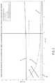
- FIG. 2is a graph showing azimuth angle resolution comparison between the present invention and a single scan estimation for a target with a SNR of 20 dBs;
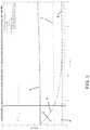
- FIG. 3is a graph showing azimuth angle resolution comparison between the present invention and a single scan estimation for a target with a SNR of 10 dBs.
- a vehicle sensing systemsuch as a driver assist system, object detection system, parking assist system and/or alert system, operates to capture sensing data exterior of the vehicle and may process the captured data to detect objects or other vehicles at or near the equipped vehicle and in the predicted path of the equipped vehicle, such as to assist a driver of the equipped vehicle in maneuvering the vehicle in a forward or rearward direction or to assist the driver in parking the vehicle in a parking space.
- the systemincludes a processor that is operable to receive sensing data from one or more sensors and to provide an output to a control that, responsive to the output, generates an alert or controls an accessory or system of the vehicle, or highlights or overlays an alert on a display screen (that may be displaying video images captured by a single rearward viewing camera or multiple cameras providing forward, side or 360 degree surround views of the area surrounding the vehicle during a reversing or low speed maneuver of the vehicle).
- a vehicle 10includes an driver assistance system or sensing system 12 that includes at least one radar sensor unit, such as a forward facing radar sensor unit 14 (and the system may optionally include multiple exterior facing sensors, such as multiple exterior facing radar sensors or cameras or other sensors, such as a rearward facing sensor at the rear of the vehicle, and a sideward/rearward facing sensor at respective sides of the vehicle), which sense regions exterior of the vehicle.
- the sensing system 12includes a control or electronic control unit (ECU) or processor that is operable to process data captured by the sensor or sensors and may detect objects or the like.
- the data transfer or signal communication from the sensor to the ECUmay comprise any suitable data or communication link, such as a vehicle network bus or the like of the equipped vehicle.
- MIMOMultiple Input Multiple Output
- Algorithms to estimate target positioning on automotive radartypically either use a coherent single scan or an incoherent set of scans.
- the algorithmuses the complex value of the different antenna phase centers for a certain range and carry out a beamforming (BF) in order to obtain the angular position of the target.
- BFbeamforming
- the ability to separate two targets separated by a narrow angleis driven by the physical antenna array size.
- the second type of target positioningutilizes a set of scans incoherently, and receives as inputs a set of target list outputs from different scans (similar to the first example). In this case, the resolution is not improved per se. Two targets close by in angle will be reported as two separate targets only when they present sufficient difference in angle.
- two vehicles far away that are in adjacent lanesmay be seen as a single vehicle. However, as they get closer to the subject vehicle, they may eventually present enough angle difference to be seen or sensed as two separate targets. Thus, at that moment, the system identifies as two targets what it was earlier or previously sensing as just one target.
- the system of the present inventionsubstantially improves the ability of an automotive radar to distinguish different targets in the angle dimension by synthesizing a virtual aperture using the car movement between scans. This allows the system to use coherent integration through a different set of scans in order to distinguish targets close by in angle in just a few scans.
- the system of the present inventiongenerates a virtual array by the vehicle position change between scans. For example, a vehicle moving at 80 km/h with a radar scan time of 30 ms yields in a virtual array size of 0.67 meters with two scans (that is, the vehicle will travel 0.67 meters between scans), 1.33 m using 3 scans and 6 m using 10 scans.
- the formed virtual array with several phase centersis significantly larger with respect to the physical antenna array size.
- the separation between contiguous phase centersis related to distance travelled by the vehicle between scans. That distance is most likely large enough to get grating lobes within a few degrees.
- This advanced knowledgemay be provided by a single scan Angle of Arrival (AoA) estimation. This implies that the maximum AoA estimation error is lower than the separation between the main lobe and the grating lobe.
- AoAAngle of Arrival
- the system of the present inventionreceives as input an ego motion estimation (an estimation of the motion of the measuring sensor disposed at the equipped or subject vehicle), a time stamp of each data acquisition or scan, a detection list for each scan with detected targets position, Doppler velocity and complex value after beamforming, and a sensor position of the measuring sensor with respect to the vehicle.
- an ego motion estimationan estimation of the motion of the measuring sensor disposed at the equipped or subject vehicle
- a time stamp of each data acquisition or scana detection list for each scan with detected targets position
- Doppler velocity and complex value after beamformingDoppler velocity and complex value after beamforming
- the dataflowincludes matching the targets between scans. For every target, there is a series of complex values which come from the detection list of every scan. For every target and scan, this value is obtained after beamforming.
- the next stepis to “flatten” the phases by taking into account the vehicle movement and the estimated target positioning by the scans.
- This “phase flattening”can be done as a geometric approach by taking into account the different positions of the radar sensor and targets.
- the remaining phasesare relative to the first position which will be 0 degrees.
- the systemperforms an assessment to check if it is possible to estimate the AoA without ambiguity. In essence, this tests if the scans maximum AoA error is within grating lobes. Targets with high SNR are more likely to be solved unambiguously.
- An AoA estimationis applied over the complex series within the angle dynamic range between grating lobes.
- the systemreports the found targets using the long synthetic aperture (SA).
- SAmay be quite long depending on the number of integrated scans, vehicle velocity and scan dwell time. In order to be able to separate at least two targets within the nominal angle resolution, ideally the number of scans integrated is at least three.
- FIGS. 2 and 3show the resolution improvement vs nominal Azimuth Angle Resolution assuming 20 dBs SNR ( FIG. 2 ) and 10 dBs SNR ( FIG. 3 ).
- the curve Ais the nominal resolution for different AoA and taking into account the single scan physical aperture.
- the accuracyis plotted as a solid line B and a dashed line C for one sigma and three sigmas, respectively.
- the line Drepresents the separation between grating lobes versus AoA.
- the SA Phase Unambiguous Regionis defined as the region where three times sigma is below the grating lobe separation curve D.
- an example resolutionis given by standard beamforming with a SA using three scans (see solid line E) and ten scans (see dashed line F).
- targets with a higher SNRshow a wider angle Unambiguous Region (the region to the left of the vertical line in FIGS. 2 and 3 ) than weak targets or targets with a lower SNR.
- the resolution powerquickly falls below 1 degree without using any super-resolution estimation method.
- an SA with 10 scansmay separate targets around approximately 5 degrees of AoA with 0.18 degree resolution employing a simple beamforming.
- the system of the present inventionthus substantially improves the ability of an automotive radar to distinguish different targets in the angle dimension.
- the systemsynthesizes a virtual aperture using the vehicle movement between scans.
- the Synthetic Aperture (SA)can be quite long depending on the number of integrated scans, vehicle velocity and scan dwell time.
- the minimum number of scans to be integratedis preferably three.
- the systemmay provide an output for a driving assist system of the vehicle, such as one or more of (i) automated parking, (ii) blind spot detection, (iii) cross traffic alert, (iv) lane change assist, (v) lane merge assist, (vi) automatic emergency braking, (vii) pedestrian detection, (viii) turn assist, (ix) terrain management, (x) collision mitigation and (xi) intersection collision mitigation.
- a driving assist system of the vehiclesuch as one or more of (i) automated parking, (ii) blind spot detection, (iii) cross traffic alert, (iv) lane change assist, (v) lane merge assist, (vi) automatic emergency braking, (vii) pedestrian detection, (viii) turn assist, (ix) terrain management, (x) collision mitigation and (xi) intersection collision mitigation.
- the outputmay be provided to an autonomous vehicle control system.
- an occupant of the vehiclemay, under particular circumstances, be desired or required to take over operation/control of the vehicle and drive the vehicle so as to avoid potential hazard for as long as the autonomous system relinquishes such control or driving. Such occupant of the vehicle thus becomes the driver of the autonomous vehicle.
- the term “driver”refers to such an occupant, even when that occupant is not actually driving the vehicle, but is situated in the vehicle so as to be able to take over control and function as the driver of the vehicle when the vehicle control system hands over control to the occupant or driver or when the vehicle control system is not operating in an autonomous or semi-autonomous mode.
- an autonomous vehiclewould be equipped with a suite of sensors, including multiple machine vision cameras deployed at the front, sides and rear of the vehicle, multiple radar sensors deployed at the front, sides and rear of the vehicle, and/or multiple lidar sensors deployed at the front, sides and rear of the vehicle.
- a suite of sensorsincluding multiple machine vision cameras deployed at the front, sides and rear of the vehicle, multiple radar sensors deployed at the front, sides and rear of the vehicle, and/or multiple lidar sensors deployed at the front, sides and rear of the vehicle.
- V2Vcar2car
- the forward viewing camera and/or the sensor of the lane determining systemmay comprise one of the cameras and/or one of the sensors of the autonomous vehicle control system.
- the sensing systemmay include a machine vision system (comprising at least one exterior viewing camera disposed at the vehicle and an image processor for processing image data captured by the at least one camera), where information is shared between the stereo radar and the machine vision system.
- a machine vision systemcomprising at least one exterior viewing camera disposed at the vehicle and an image processor for processing image data captured by the at least one camera
- the systemmay include two or more individual radars, having individual or multiple Tx (transmitters) and Rx (receivers) on an antenna array, and may utilize aspects of the systems described in U.S. Pat. Nos. 9,753,121; 9,689,967; 9,599,702; 9,575,160; 9,146,898; 9,036,026; 8,027,029; 8,013,780; 6,825,455; 7,053,357; 7,408,627; 7,405,812; 7,379,163; 7,379,100; 7,375,803; 7,352,454; 7,340,077; 7,321,111; 7,310,431; 7,283,213; 7,212,663; 7,203,356; 7,176,438; 7,157,685; 6,919,549; 6,906,793; 6,876,775; 6,710,770; 6,690,354; 6,678,039; 6,674,895 and/or 6,587,186, and/or
Landscapes
- Engineering & Computer Science (AREA)
- Remote Sensing (AREA)
- Radar, Positioning & Navigation (AREA)
- Physics & Mathematics (AREA)
- Computer Networks & Wireless Communication (AREA)
- General Physics & Mathematics (AREA)
- Electromagnetism (AREA)
- Signal Processing (AREA)
- Radar Systems Or Details Thereof (AREA)
- Traffic Control Systems (AREA)
Abstract
Description
The present application claims the filing benefits of U.S. provisional application Ser. No. 62/555,222, filed Sep. 7, 2017, which is hereby incorporated herein by reference in its entirety.
The present invention relates generally to a vehicle sensing system for a vehicle and, more particularly, to a vehicle sensing system that utilizes one or more sensors at a vehicle to provide a field of sensing at or around the vehicle.
Use of imaging sensors or ultrasonic sensors or radar sensors in vehicle sensing systems is common and known. Examples of such known systems are described in U.S. Pat. Nos. 8,013,780 and 5,949,331 and/or U.S. publication No. US-2010-0245066 and/or International Publication No. WO 2011/090484, which are hereby incorporated herein by reference in their entireties.
The present invention provides a driver assistance system or sensing system for a vehicle that utilizes a sensor module or system disposed at the vehicle and comprising at least one radar sensor disposed at the vehicle and having a field of sensing exterior of the vehicle. The at least one radar sensor comprises multiple Tx (transmitters) and Rx (receivers) to provide high definition, fine resolution in azimuth and/or elevation to determine high definition radar reflection responses for objects and surfaces detected by the system. The system includes a control, where outputs (such as radar data acquisitions of multiple scans) of the at least one radar sensor are communicated to the control, and where the control, responsive to the outputs of the at least one radar sensor, detects the presence of objects in the field of sensing of the radar sensor or sensors. The system uses multiple scans to synthesize a virtual aperture using the vehicle position change between the scans. The system provides enhanced accuracy in determining the location of a detected object relative to the vehicle and sensor(s).
The present invention provides a means to substantially or drastically improve the ability of an automotive radar system to distinguish different targets in the angle dimension. The system synthesizes a virtual aperture using the vehicle movement between scans. This Synthetic Aperture (SA) or synthesized aperture can be quite long depending on the number of integrated scans, vehicle velocity and scan dwell time. In order to be able to separate at least two targets within a nominal angle resolution, the minimum number of scans to be integrated is three.
These and other objects, advantages, purposes and features of the present invention will become apparent upon review of the following specification in conjunction with the drawings.
A vehicle sensing system, such as a driver assist system, object detection system, parking assist system and/or alert system, operates to capture sensing data exterior of the vehicle and may process the captured data to detect objects or other vehicles at or near the equipped vehicle and in the predicted path of the equipped vehicle, such as to assist a driver of the equipped vehicle in maneuvering the vehicle in a forward or rearward direction or to assist the driver in parking the vehicle in a parking space. The system includes a processor that is operable to receive sensing data from one or more sensors and to provide an output to a control that, responsive to the output, generates an alert or controls an accessory or system of the vehicle, or highlights or overlays an alert on a display screen (that may be displaying video images captured by a single rearward viewing camera or multiple cameras providing forward, side or 360 degree surround views of the area surrounding the vehicle during a reversing or low speed maneuver of the vehicle).
Referring now to the drawings and the illustrative embodiments depicted therein, avehicle 10 includes an driver assistance system orsensing system 12 that includes at least one radar sensor unit, such as a forward facing radar sensor unit14 (and the system may optionally include multiple exterior facing sensors, such as multiple exterior facing radar sensors or cameras or other sensors, such as a rearward facing sensor at the rear of the vehicle, and a sideward/rearward facing sensor at respective sides of the vehicle), which sense regions exterior of the vehicle. Thesensing system 12 includes a control or electronic control unit (ECU) or processor that is operable to process data captured by the sensor or sensors and may detect objects or the like. The data transfer or signal communication from the sensor to the ECU may comprise any suitable data or communication link, such as a vehicle network bus or the like of the equipped vehicle.
Some automotive radars use MIMO (Multiple Input Multiple Output) techniques to create an effective virtual antenna aperture, which is significantly larger than the real antenna aperture, and delivers much better angular resolution than conventional radars, such as, for example, conventional scanning radars.
Algorithms to estimate target positioning on automotive radar typically either use a coherent single scan or an incoherent set of scans. When using a single scan coherently, the algorithm uses the complex value of the different antenna phase centers for a certain range and carry out a beamforming (BF) in order to obtain the angular position of the target. In this case, the ability to separate two targets separated by a narrow angle is driven by the physical antenna array size. The second type of target positioning utilizes a set of scans incoherently, and receives as inputs a set of target list outputs from different scans (similar to the first example). In this case, the resolution is not improved per se. Two targets close by in angle will be reported as two separate targets only when they present sufficient difference in angle. For example, two vehicles far away that are in adjacent lanes may be seen as a single vehicle. However, as they get closer to the subject vehicle, they may eventually present enough angle difference to be seen or sensed as two separate targets. Thus, at that moment, the system identifies as two targets what it was earlier or previously sensing as just one target.
The system of the present invention substantially improves the ability of an automotive radar to distinguish different targets in the angle dimension by synthesizing a virtual aperture using the car movement between scans. This allows the system to use coherent integration through a different set of scans in order to distinguish targets close by in angle in just a few scans. To this end, the system of the present invention generates a virtual array by the vehicle position change between scans. For example, a vehicle moving at 80 km/h with a radar scan time of 30 ms yields in a virtual array size of 0.67 meters with two scans (that is, the vehicle will travel 0.67 meters between scans), 1.33 m using 3 scans and 6 m using 10 scans. Thus, the formed virtual array with several phase centers is significantly larger with respect to the physical antenna array size.
The separation between contiguous phase centers is related to distance travelled by the vehicle between scans. That distance is most likely large enough to get grating lobes within a few degrees. Thus, the use of this technique requires knowledge in advance in order to avoid confusing main lobes with grating lobes. This advanced knowledge may be provided by a single scan Angle of Arrival (AoA) estimation. This implies that the maximum AoA estimation error is lower than the separation between the main lobe and the grating lobe.
The system of the present invention receives as input an ego motion estimation (an estimation of the motion of the measuring sensor disposed at the equipped or subject vehicle), a time stamp of each data acquisition or scan, a detection list for each scan with detected targets position, Doppler velocity and complex value after beamforming, and a sensor position of the measuring sensor with respect to the vehicle.
The dataflow includes matching the targets between scans. For every target, there is a series of complex values which come from the detection list of every scan. For every target and scan, this value is obtained after beamforming.
The next step is to “flatten” the phases by taking into account the vehicle movement and the estimated target positioning by the scans. This “phase flattening” can be done as a geometric approach by taking into account the different positions of the radar sensor and targets. The remaining phases are relative to the first position which will be 0 degrees.
Then, the system performs an assessment to check if it is possible to estimate the AoA without ambiguity. In essence, this tests if the scans maximum AoA error is within grating lobes. Targets with high SNR are more likely to be solved unambiguously. An AoA estimation is applied over the complex series within the angle dynamic range between grating lobes. Finally, the system reports the found targets using the long synthetic aperture (SA). This SA may be quite long depending on the number of integrated scans, vehicle velocity and scan dwell time. In order to be able to separate at least two targets within the nominal angle resolution, ideally the number of scans integrated is at least three.
For example, for an Azimuth dimension, the following parameters may be taken into account: vehicle velocity of 80 km/h, scan time of 30 ms, sensor frequency of 79 GHz (wavelength of 3.8 mm), 7 physical phase centers, and a 2 wavelength separation between physical phase centers.FIGS. 2 and 3 show the resolution improvement vs nominal Azimuth Angle Resolution assuming 20 dBs SNR (FIG. 2 ) and 10 dBs SNR (FIG. 3 ).
The curve A is the nominal resolution for different AoA and taking into account the single scan physical aperture. The accuracy is plotted as a solid line B and a dashed line C for one sigma and three sigmas, respectively. The line D represents the separation between grating lobes versus AoA. Thus, the SA Phase Unambiguous Region is defined as the region where three times sigma is below the grating lobe separation curve D. Finally, an example resolution is given by standard beamforming with a SA using three scans (see solid line E) and ten scans (see dashed line F).
As can be seen with reference toFIGS. 2 and 3 , targets with a higher SNR show a wider angle Unambiguous Region (the region to the left of the vertical line inFIGS. 2 and 3 ) than weak targets or targets with a lower SNR. The resolution power quickly falls below 1 degree without using any super-resolution estimation method. As an example, an SA with 10 scans may separate targets around approximately 5 degrees of AoA with 0.18 degree resolution employing a simple beamforming.
The system of the present invention thus substantially improves the ability of an automotive radar to distinguish different targets in the angle dimension. The system synthesizes a virtual aperture using the vehicle movement between scans. The Synthetic Aperture (SA) can be quite long depending on the number of integrated scans, vehicle velocity and scan dwell time. In order to be able to separate at least two targets within the nominal angle resolution, the minimum number of scans to be integrated is preferably three.
The system may provide an output for a driving assist system of the vehicle, such as one or more of (i) automated parking, (ii) blind spot detection, (iii) cross traffic alert, (iv) lane change assist, (v) lane merge assist, (vi) automatic emergency braking, (vii) pedestrian detection, (viii) turn assist, (ix) terrain management, (x) collision mitigation and (xi) intersection collision mitigation. Optionally, the output may be provided to an autonomous vehicle control system.
For autonomous vehicles suitable for deployment with the system of the present invention, an occupant of the vehicle may, under particular circumstances, be desired or required to take over operation/control of the vehicle and drive the vehicle so as to avoid potential hazard for as long as the autonomous system relinquishes such control or driving. Such occupant of the vehicle thus becomes the driver of the autonomous vehicle. As used herein, the term “driver” refers to such an occupant, even when that occupant is not actually driving the vehicle, but is situated in the vehicle so as to be able to take over control and function as the driver of the vehicle when the vehicle control system hands over control to the occupant or driver or when the vehicle control system is not operating in an autonomous or semi-autonomous mode.
Typically an autonomous vehicle would be equipped with a suite of sensors, including multiple machine vision cameras deployed at the front, sides and rear of the vehicle, multiple radar sensors deployed at the front, sides and rear of the vehicle, and/or multiple lidar sensors deployed at the front, sides and rear of the vehicle. Typically, such an autonomous vehicle will also have wireless two way communication with other vehicles or infrastructure, such as via a car2car (V2V) or car2x communication system. The forward viewing camera and/or the sensor of the lane determining system may comprise one of the cameras and/or one of the sensors of the autonomous vehicle control system.
The sensing system may include a machine vision system (comprising at least one exterior viewing camera disposed at the vehicle and an image processor for processing image data captured by the at least one camera), where information is shared between the stereo radar and the machine vision system.
The system may include two or more individual radars, having individual or multiple Tx (transmitters) and Rx (receivers) on an antenna array, and may utilize aspects of the systems described in U.S. Pat. Nos. 9,753,121; 9,689,967; 9,599,702; 9,575,160; 9,146,898; 9,036,026; 8,027,029; 8,013,780; 6,825,455; 7,053,357; 7,408,627; 7,405,812; 7,379,163; 7,379,100; 7,375,803; 7,352,454; 7,340,077; 7,321,111; 7,310,431; 7,283,213; 7,212,663; 7,203,356; 7,176,438; 7,157,685; 6,919,549; 6,906,793; 6,876,775; 6,710,770; 6,690,354; 6,678,039; 6,674,895 and/or 6,587,186, and/or International Publication Nos. WO 2018/007995 and/or WO 2011/090484, and/or U.S. Publication Nos. US-2018-0231635; US-2018-0045812; US-2018-0015875; US-2017-0356994; US-2017-0315231; US-2017-0276788; US-2017-0254873; US-2017-0222311, which are hereby incorporated herein by reference in their entireties.
Changes and modifications in the specifically described embodiments can be carried out without departing from the principles of the invention, which is intended to be limited only by the scope of the appended claims, as interpreted according to the principles of patent law including the doctrine of equivalents.
Claims (20)
1. A sensing system for a vehicle, said sensing system comprising:
at least one radar sensor disposed at a vehicle equipped with said sensing system and having a field of sensing exterior of the equipped vehicle;
wherein said at least one radar sensor comprises multiple transmitting antennas and multiple receiving antennas, and wherein said transmitting antennas transmit signals and said receiving antennas receive the signals reflected off objects;
a control comprising a processor, wherein multiple scans of radar data sensed by said at least one radar sensor are received at said control and processed at said processor;
wherein a vehicle motion estimation is received at said control;
wherein said control, responsive to processing at the processor of the received multiple scans of sensed radar data, detects a presence of two or more objects exterior the equipped vehicle and within the field of sensing of said at least one radar sensor; and
wherein said control, responsive at least in part to processing at the processor of the received multiple scans of sensed radar data and the received vehicle motion estimation, synthesizes a virtual aperture and matches objects detected in the multiple scans and determines a separation between two detected objects by tracking the detected objects over two or more scans.
2. The sensing system ofclaim 1 , wherein the received multiple scans of sensed radar data comprises radar data acquisitions for at least three consecutive scans by said at least one radar sensor.
3. The sensing system ofclaim 2 , wherein each radar data acquisition is time stamped.
4. The sensing system ofclaim 3 , wherein said control receives a detection list for each scan with detected objects' positions, Doppler velocities and complex values.
5. The sensing system ofclaim 4 , wherein said control determines angles toward detected objects responsive to a sensor position of said at least one radar sensor at the equipped vehicle.
6. The sensing system ofclaim 2 , wherein said control flattens phases by taking into account the vehicle motion and estimated object positioning by the scans.
7. The sensing system ofclaim 6 , wherein said control determines if a maximum angle of arrival error of the scans is within grating lobes emitted by the transmitting antennas.
8. The sensing system ofclaim 7 , wherein said control applies an angle of arrival estimation over a complex series within an angle dynamic range between the grating lobes.
9. The sensing system ofclaim 1 , wherein a vision system of the equipped vehicle comprises at least one exterior viewing camera disposed at the equipped vehicle and an image processor for processing image data captured by the at least one exterior viewing camera, and wherein information is shared between said sensing system and the vision system of the equipped vehicle.
10. The sensing system ofclaim 1 , wherein said sensing system comprises two or more individual radar sensors, each having multiple transmitting antennas and receiving antennas on an antenna array, and wherein information is shared between the individual radar sensors operating in stereo to determine high definition radar reflection responses for objects detected by said sensing system.
11. The sensing system ofclaim 1 , wherein said at least one radar sensor is disposed at a front portion of the equipped vehicle and senses forward of the equipped vehicle.
12. The sensing system ofclaim 1 , wherein said sensing system provides an output for at least one driving assist system function selected from the group consisting of (i) automated parking, (ii) blind spot detection, (iii) cross traffic alert, (iv) lane change assist, (v) lane merge assist, (vi) automatic emergency braking, (vii) pedestrian detection, (viii) turn assist, (ix) terrain management, (x) collision mitigation and (xi) intersection collision mitigation.
13. A sensing system for a vehicle, said sensing system comprising:
at least one radar sensor disposed at a vehicle equipped with said sensing system and having a field of sensing exterior of the equipped vehicle;
wherein said at least one radar sensor comprises multiple transmitting antennas and multiple receiving antennas, and wherein said transmitting antennas transmit signals and said receiving antennas receive the signals reflected off objects;
a control comprising a processor, wherein multiple scans of radar data sensed by said at least one radar sensor are received at said control and processed at said processor;
wherein the received multiple scans of sensed radar data comprises radar data acquisitions for at least three consecutive scans by said at least one radar sensor;
wherein a vehicle motion estimation is received at said control;
wherein said control, responsive to processing at the processor of the received multiple scans of sensed radar data, detects a presence of two or more objects exterior the equipped vehicle and within the field of sensing of said at least one radar sensor;
wherein said control, responsive at least in part to processing at the processor of the received multiple scans of sensed radar data and the received vehicle motion estimation, synthesizes a virtual aperture and matches objects detected in the multiple scans and determines a separation between two detected objects by tracking the detected objects over two or more scans; and
wherein said sensing system provides an output for at least one driving assist system function selected from the group consisting of (i) automated parking, (ii) blind spot detection, (iii) cross traffic alert, (iv) lane change assist, (v) lane merge assist, (vi) automatic emergency braking, (vii) pedestrian detection, (viii) turn assist, (ix) terrain management, (x) collision mitigation and (xi) intersection collision mitigation.
14. The sensing system ofclaim 13 , wherein said control receives a detection list for each scan with detected objects' positions, Doppler velocities and complex values.
15. The sensing system ofclaim 13 , wherein said at least one radar sensor is disposed at a front portion of the equipped vehicle and senses forward of the equipped vehicle.
16. The sensing system ofclaim 13 , wherein said sensing system comprises two or more individual radar sensors, each having multiple transmitting antennas and receiving antennas on an antenna array, and wherein information is shared between the individual radar sensors operating in stereo to determine high definition radar reflection responses for objects detected by said sensing system.
17. A sensing system for a vehicle, said sensing system comprising:
at least one radar sensor disposed at a vehicle equipped with said sensing system and having a field of sensing exterior of the equipped vehicle;
wherein said at least one radar sensor comprises multiple transmitting antennas and multiple receiving antennas, and wherein said transmitting antennas transmit signals and said receiving antennas receive the signals reflected off objects;
a control comprising a processor, wherein multiple scans of radar data sensed by said at least one radar sensor are received at said control and processed at said processor;
wherein a vehicle motion estimation is received at said control;
wherein said control, responsive to processing at the processor of the received multiple scans of sensed radar data, detects a presence of two or more objects exterior the equipped vehicle and within the field of sensing of said at least one radar sensor;
wherein said control, responsive at least in part to processing at the processor of the received multiple scans of sensed radar data and the received vehicle motion estimation, synthesizes a virtual aperture and matches objects detected in the multiple scans and determines a separation between two detected objects by tracking the detected objects over two or more scans;
wherein said control flattens phases by taking into account the vehicle motion and estimated object positioning by the scans, and wherein said control determines if a maximum angle of arrival error of the scans is within grating lobes emitted by the transmitting antennas, and wherein said control applies an angle of arrival estimation over a complex series within an angle dynamic range between the grating lobes; and
wherein said sensing system provides an output for at least one driving assist system function selected from the group consisting of (i) automated parking, (ii) blind spot detection, (iii) cross traffic alert, (iv) lane change assist, (v) lane merge assist, (vi) automatic emergency braking, (vii) pedestrian detection, (viii) turn assist, (ix) terrain management, (x) collision mitigation and (xi) intersection collision mitigation.
18. The sensing system ofclaim 17 , wherein each radar data acquisition is time stamped.
19. The sensing system ofclaim 17 , wherein said control receives a detection list for each scan with detected objects' positions, Doppler velocities and complex values.
20. The sensing system ofclaim 17 , wherein said at least one radar sensor is disposed at a front portion of the equipped vehicle and senses forward of the equipped vehicle.
Priority Applications (3)
| Application Number | Priority Date | Filing Date | Title |
|---|---|---|---|
| US16/123,265US10877148B2 (en) | 2017-09-07 | 2018-09-06 | Vehicle radar sensing system with enhanced angle resolution using synthesized aperture |
| US17/247,692US11703587B2 (en) | 2017-09-07 | 2020-12-21 | Vehicle radar sensing system with enhanced angle resolution |
| US18/353,195US12025696B2 (en) | 2017-09-07 | 2023-07-17 | Vehicle radar sensing system with enhanced angle resolution |
Applications Claiming Priority (2)
| Application Number | Priority Date | Filing Date | Title |
|---|---|---|---|
| US201762555222P | 2017-09-07 | 2017-09-07 | |
| US16/123,265US10877148B2 (en) | 2017-09-07 | 2018-09-06 | Vehicle radar sensing system with enhanced angle resolution using synthesized aperture |
Related Child Applications (1)
| Application Number | Title | Priority Date | Filing Date |
|---|---|---|---|
| US17/247,692ContinuationUS11703587B2 (en) | 2017-09-07 | 2020-12-21 | Vehicle radar sensing system with enhanced angle resolution |
Publications (2)
| Publication Number | Publication Date |
|---|---|
| US20190072668A1 US20190072668A1 (en) | 2019-03-07 |
| US10877148B2true US10877148B2 (en) | 2020-12-29 |
Family
ID=65517931
Family Applications (3)
| Application Number | Title | Priority Date | Filing Date |
|---|---|---|---|
| US16/123,265Active2039-07-25US10877148B2 (en) | 2017-09-07 | 2018-09-06 | Vehicle radar sensing system with enhanced angle resolution using synthesized aperture |
| US17/247,692Active2039-06-03US11703587B2 (en) | 2017-09-07 | 2020-12-21 | Vehicle radar sensing system with enhanced angle resolution |
| US18/353,195ActiveUS12025696B2 (en) | 2017-09-07 | 2023-07-17 | Vehicle radar sensing system with enhanced angle resolution |
Family Applications After (2)
| Application Number | Title | Priority Date | Filing Date |
|---|---|---|---|
| US17/247,692Active2039-06-03US11703587B2 (en) | 2017-09-07 | 2020-12-21 | Vehicle radar sensing system with enhanced angle resolution |
| US18/353,195ActiveUS12025696B2 (en) | 2017-09-07 | 2023-07-17 | Vehicle radar sensing system with enhanced angle resolution |
Country Status (1)
| Country | Link |
|---|---|
| US (3) | US10877148B2 (en) |
Cited By (3)
| Publication number | Priority date | Publication date | Assignee | Title |
|---|---|---|---|---|
| US11035942B2 (en)* | 2018-09-06 | 2021-06-15 | Hyundai Motor Company | Method and device for correcting target angle error of radar sensor |
| US20220268888A1 (en)* | 2021-02-19 | 2022-08-25 | Mando Mobility Solutions Corporation | Radar control device and method |
| US11703587B2 (en) | 2017-09-07 | 2023-07-18 | Magna Electronics Inc. | Vehicle radar sensing system with enhanced angle resolution |
Families Citing this family (23)
| Publication number | Priority date | Publication date | Assignee | Title |
|---|---|---|---|---|
| US10768298B2 (en) | 2016-06-14 | 2020-09-08 | Magna Electronics Inc. | Vehicle sensing system with 360 degree near range sensing |
| US11454719B2 (en) | 2016-07-08 | 2022-09-27 | Magna Electronics Inc. | 2D MIMO radar system for vehicle |
| US10852418B2 (en) | 2016-08-24 | 2020-12-01 | Magna Electronics Inc. | Vehicle sensor with integrated radar and image sensors |
| US10677894B2 (en) | 2016-09-06 | 2020-06-09 | Magna Electronics Inc. | Vehicle sensing system for classification of vehicle model |
| US10703341B2 (en) | 2017-02-03 | 2020-07-07 | Magna Electronics Inc. | Vehicle sensor housing with theft protection |
| US11536829B2 (en) | 2017-02-16 | 2022-12-27 | Magna Electronics Inc. | Vehicle radar system with radar embedded into radome |
| US10782388B2 (en) | 2017-02-16 | 2020-09-22 | Magna Electronics Inc. | Vehicle radar system with copper PCB |
| US10962638B2 (en) | 2017-09-07 | 2021-03-30 | Magna Electronics Inc. | Vehicle radar sensing system with surface modeling |
| US10962641B2 (en) | 2017-09-07 | 2021-03-30 | Magna Electronics Inc. | Vehicle radar sensing system with enhanced accuracy using interferometry techniques |
| US11150342B2 (en) | 2017-09-07 | 2021-10-19 | Magna Electronics Inc. | Vehicle radar sensing system with surface segmentation using interferometric statistical analysis |
| US11486968B2 (en) | 2017-11-15 | 2022-11-01 | Magna Electronics Inc. | Vehicle Lidar sensing system with sensor module |
| US11454720B2 (en) | 2018-11-28 | 2022-09-27 | Magna Electronics Inc. | Vehicle radar system with enhanced wave guide antenna system |
| US12044794B2 (en) | 2019-02-26 | 2024-07-23 | Magna Electronics Inc. | Vehicular radar system with automatic sensor alignment |
| US11333739B2 (en) | 2019-02-26 | 2022-05-17 | Magna Electronics Inc. | Vehicular radar system with automatic sensor alignment |
| DE102019210506A1 (en) | 2019-07-16 | 2021-01-21 | Volkswagen Aktiengesellschaft | Method and device for detecting an environment |
| US11320830B2 (en) | 2019-10-28 | 2022-05-03 | Deere & Company | Probabilistic decision support for obstacle detection and classification in a working area |
| US11536831B2 (en) | 2020-06-15 | 2022-12-27 | Gm Cruise Holdings Llc | Systems and methods for high velocity resolution high update rate radar for autonomous vehicles |
| US11639992B2 (en)* | 2020-06-25 | 2023-05-02 | Intel Corporation | Apparatus, system and method of generating radar information based on an amplitude phase estimation calculation |
| JP7276280B2 (en)* | 2020-08-18 | 2023-05-18 | トヨタ自動車株式会社 | VEHICLE IMAGE RECORDING DEVICE AND VEHICLE IMAGE RECORDING METHOD |
| US11802939B2 (en)* | 2020-11-16 | 2023-10-31 | Samsung Electronics Co., Ltd. | Method and apparatus with radar signal processing |
| US12007476B2 (en) | 2021-09-13 | 2024-06-11 | Magna Electronics Inc. | Method for detecting objects via a vehicular sensing system |
| US12345804B2 (en)* | 2021-09-20 | 2025-07-01 | Deere & Company | Systems and methods for adjusting vehicle lane position |
| JP7490017B2 (en)* | 2022-05-19 | 2024-05-24 | 三菱電機株式会社 | Automatic Driving Device |
Citations (100)
| Publication number | Priority date | Publication date | Assignee | Title |
|---|---|---|---|---|
| US4943796A (en) | 1989-06-09 | 1990-07-24 | Lee Y C | Rear view mirror mounted reversing distance sensor |
| US5550677A (en) | 1993-02-26 | 1996-08-27 | Donnelly Corporation | Automatic rearview mirror system using a photosensor array |
| US5585798A (en) | 1993-07-07 | 1996-12-17 | Mazda Motor Corporation | Obstacle detection system for automotive vehicle |
| US5670935A (en) | 1993-02-26 | 1997-09-23 | Donnelly Corporation | Rearview vision system for vehicle including panoramic view |
| US5715093A (en) | 1994-07-19 | 1998-02-03 | Donnelly Corporation | Automatic rearview mirror system with automatic headlight activation |
| US5796094A (en) | 1993-02-26 | 1998-08-18 | Donnelly Corporation | Vehicle headlight control using imaging sensor |
| US5877897A (en) | 1993-02-26 | 1999-03-02 | Donnelly Corporation | Automatic rearview mirror, vehicle lighting control and vehicle interior monitoring system using a photosensor array |
| US6057754A (en) | 1997-08-11 | 2000-05-02 | Fuji Jukogyo Kabushiki Kaisha | Drive assist system for motor vehicle |
| US6067110A (en) | 1995-07-10 | 2000-05-23 | Honda Giken Kogyo Kabushiki Kaisha | Object recognizing device |
| US6085151A (en) | 1998-01-20 | 2000-07-04 | Automotive Systems Laboratory, Inc. | Predictive collision sensing system |
| US6118410A (en) | 1999-07-29 | 2000-09-12 | General Motors Corporation | Automobile roof antenna shelf |
| US6118401A (en) | 1996-07-01 | 2000-09-12 | Sun Microsystems, Inc. | Aircraft ground collision avoidance system and method |
| US6201642B1 (en) | 1999-07-27 | 2001-03-13 | Donnelly Corporation | Vehicular vision system with a wide angle lens including a diffractive element |
| US6216540B1 (en) | 1995-06-06 | 2001-04-17 | Robert S. Nelson | High resolution device and method for imaging concealed objects within an obscuring medium |
| US6313454B1 (en) | 1999-07-02 | 2001-11-06 | Donnelly Corporation | Rain sensor |
| US6353392B1 (en) | 1997-10-30 | 2002-03-05 | Donnelly Corporation | Rain sensor with fog discrimination |
| US6396397B1 (en) | 1993-02-26 | 2002-05-28 | Donnelly Corporation | Vehicle imaging system with stereo imaging |
| US6492935B1 (en) | 1999-09-29 | 2002-12-10 | Fujitsu Ten Limited | Peripheral monitoring sensor |
| US6498620B2 (en) | 1993-02-26 | 2002-12-24 | Donnelly Corporation | Vision system for a vehicle including an image capture device and a display system having a long focal length |
| US6580385B1 (en) | 1999-05-26 | 2003-06-17 | Robert Bosch Gmbh | Object detection system |
| US6587186B2 (en) | 2000-06-06 | 2003-07-01 | Canesta, Inc. | CMOS-compatible three-dimensional image sensing using reduced peak energy |
| US20030138132A1 (en) | 1997-04-02 | 2003-07-24 | Stam Joseph S. | Vehicle lamp control |
| US20030201929A1 (en) | 2002-04-24 | 2003-10-30 | Lutter Robert Pierce Pierce | Multi-sensor system |
| US6674895B2 (en) | 1999-09-22 | 2004-01-06 | Canesta, Inc. | Methods for enhancing performance and data acquired from three-dimensional image systems |
| US6678039B2 (en) | 2001-05-23 | 2004-01-13 | Canesta, Inc. | Method and system to enhance dynamic range conversion useable with CMOS three-dimensional imaging |
| US6690268B2 (en) | 2000-03-02 | 2004-02-10 | Donnelly Corporation | Video mirror systems incorporating an accessory module |
| US6690354B2 (en) | 2000-11-19 | 2004-02-10 | Canesta, Inc. | Method for enhancing performance in a system utilizing an array of sensors that sense at least two-dimensions |
| US6710770B2 (en) | 2000-02-11 | 2004-03-23 | Canesta, Inc. | Quasi-three-dimensional method and apparatus to detect and localize interaction of user-object and virtual transfer device |
| US6717610B1 (en) | 1998-11-25 | 2004-04-06 | Donnelly Corporation | Wide angle image capture system for vehicle |
| US6757109B2 (en) | 1999-07-27 | 2004-06-29 | Donnelly Corporation | Plastic lens system for vehicle imaging system |
| US6795014B2 (en) | 2002-10-28 | 2004-09-21 | Hyundai Motor Company | Method and apparatus for detecting vehicle distance |
| US6825455B1 (en) | 1996-09-05 | 2004-11-30 | Rudolf Schwarte | Method and apparatus for photomixing |
| US6831591B2 (en) | 2002-10-25 | 2004-12-14 | Omron Corporation | Radar device for a vehicle |
| EP1506893A2 (en) | 2003-08-09 | 2005-02-16 | Audi Ag | Vehicle with detection and analyse of the objects around the vehicle |
| US6876775B2 (en) | 2001-02-16 | 2005-04-05 | Canesta, Inc. | Technique for removing blurring from a captured image |
| US20050104089A1 (en) | 2002-02-05 | 2005-05-19 | Engelmann Michael G. | Visible/near infrared image sensor |
| US6903677B2 (en) | 2003-03-28 | 2005-06-07 | Fujitsu Limited | Collision prediction device, method of predicting collision, and computer product |
| US6906793B2 (en) | 2000-12-11 | 2005-06-14 | Canesta, Inc. | Methods and devices for charge management for three-dimensional sensing |
| US6919549B2 (en) | 2003-04-11 | 2005-07-19 | Canesta, Inc. | Method and system to differentially enhance sensor dynamic range |
| US6941211B1 (en) | 2000-08-17 | 2005-09-06 | Hitachi, Ltd. | Measurement controller for vehicle |
| US6946978B2 (en) | 2002-04-25 | 2005-09-20 | Donnelly Corporation | Imaging system for vehicle |
| US7004606B2 (en) | 2002-04-23 | 2006-02-28 | Donnelly Corporation | Automatic headlamp control |
| US7005974B2 (en) | 2002-04-19 | 2006-02-28 | Donnelly Corporation | Vehicle imaging system |
| US7012560B2 (en) | 2001-10-05 | 2006-03-14 | Robert Bosch Gmbh | Object sensing apparatus |
| US7038577B2 (en) | 2002-05-03 | 2006-05-02 | Donnelly Corporation | Object detection system for vehicle |
| US20060091654A1 (en) | 2004-11-04 | 2006-05-04 | Autoliv Asp, Inc. | Sensor system with radar sensor and vision sensor |
| US7042389B2 (en) | 2004-04-09 | 2006-05-09 | Denso Corporation | Device for detecting object in front of vehicle |
| US7123168B2 (en) | 2002-04-25 | 2006-10-17 | Donnelly Corporation | Driving separation distance indicator |
| US7157685B2 (en) | 2004-04-12 | 2007-01-02 | Canesta, Inc. | Method and system to enhance differential dynamic range and signal/noise in CMOS range finding systems using differential sensors |
| US7176830B2 (en) | 2004-11-26 | 2007-02-13 | Omron Corporation | Image processing system for mounting to a vehicle |
| US7176438B2 (en) | 2003-04-11 | 2007-02-13 | Canesta, Inc. | Method and system to differentially enhance sensor dynamic range using enhanced common mode reset |
| US7203356B2 (en) | 2002-04-11 | 2007-04-10 | Canesta, Inc. | Subject segmentation and tracking using 3D sensing technology for video compression in multimedia applications |
| US7212663B2 (en) | 2002-06-19 | 2007-05-01 | Canesta, Inc. | Coded-array technique for obtaining depth and other position information of an observed object |
| US7283213B2 (en) | 2005-02-08 | 2007-10-16 | Canesta, Inc. | Method and system to correct motion blur and reduce signal transients in time-of-flight sensor systems |
| US7310431B2 (en) | 2002-04-10 | 2007-12-18 | Canesta, Inc. | Optical methods for remotely measuring objects |
| US7321111B2 (en) | 2004-04-12 | 2008-01-22 | Canesta, Inc. | Method and system to enhance differential dynamic range and signal/noise in CMOS range finding systems using differential sensors |
| US7340077B2 (en) | 2002-02-15 | 2008-03-04 | Canesta, Inc. | Gesture recognition system using depth perceptive sensors |
| US7352454B2 (en) | 2000-11-09 | 2008-04-01 | Canesta, Inc. | Methods and devices for improved charge management for three-dimensional and color sensing |
| US7375803B1 (en) | 2006-05-18 | 2008-05-20 | Canesta, Inc. | RGBZ (red, green, blue, z-depth) filter system usable with sensor systems, including sensor systems with synthetic mirror enhanced three-dimensional imaging |
| US7379100B2 (en) | 2004-02-12 | 2008-05-27 | Canesta, Inc. | Method and system to increase dynamic range of time-of-flight (TOF) and/or imaging sensors |
| US7379163B2 (en) | 2005-02-08 | 2008-05-27 | Canesta, Inc. | Method and system for automatic gain control of sensors in time-of-flight systems |
| US7405812B1 (en) | 2006-05-18 | 2008-07-29 | Canesta, Inc. | Method and system to avoid inter-system interference for phase-based time-of-flight systems |
| US7408627B2 (en) | 2005-02-08 | 2008-08-05 | Canesta, Inc. | Methods and system to quantify depth data accuracy in three-dimensional sensors using single frame capture |
| US7432848B2 (en) | 2005-12-05 | 2008-10-07 | Alpine Electronics, Inc. | Inter-vehicle distance detecting device and inter-vehicle distance detecting method |
| US7526103B2 (en) | 2004-04-15 | 2009-04-28 | Donnelly Corporation | Imaging system for vehicle |
| US7613568B2 (en) | 2003-07-11 | 2009-11-03 | Toyota Jidosha Kabushiki Kaisha | Crash-safe vehicle control system |
| US20100001897A1 (en) | 2007-01-25 | 2010-01-07 | Lyman Niall R | Radar Sensing System for Vehicle |
| US7706978B2 (en) | 2005-09-02 | 2010-04-27 | Delphi Technologies, Inc. | Method for estimating unknown parameters for a vehicle object detection system |
| US7765065B2 (en) | 2001-06-28 | 2010-07-27 | Robert Bosch Gmbh | Method and device for influencing at least one parameter on a vehicle |
| US20100245066A1 (en) | 2007-10-23 | 2010-09-30 | Sarioglu Guner R | Automotive Ultrasonic Sensor System with Independent Wire Harness |
| US20110037640A1 (en) | 2009-08-13 | 2011-02-17 | Tk Holdings Inc. | Object sensing system |
| US20110148691A1 (en)* | 2009-12-18 | 2011-06-23 | Raytheon Company | Distributed Sensor SAR Processing System |
| WO2011090484A1 (en) | 2010-01-22 | 2011-07-28 | Massa Products Corporation | Hidden ultrasonic transducer |
| EP2359159A1 (en)* | 2008-11-11 | 2011-08-24 | Saab AB | Sar radar system |
| US8027029B2 (en) | 2007-11-07 | 2011-09-27 | Magna Electronics Inc. | Object detection and tracking system |
| US20130215271A1 (en) | 2012-02-22 | 2013-08-22 | Magna Electronics, Inc. | Indicia and camera assembly for a vehicle |
| US20140028494A1 (en)* | 2012-07-26 | 2014-01-30 | The Aerospace Corporation | Virtual Aperture Radar |
| US8698894B2 (en) | 2006-02-07 | 2014-04-15 | Magna Electronics Inc. | Camera mounted at rear of vehicle |
| US9036026B2 (en) | 2009-06-12 | 2015-05-19 | Magna Electronics | Scalable integrated electronic control unit for vehicle |
| US9146898B2 (en) | 2011-10-27 | 2015-09-29 | Magna Electronics Inc. | Driver assist system with algorithm switching |
| US9575160B1 (en) | 2016-04-25 | 2017-02-21 | Uhnder, Inc. | Vehicular radar sensing system utilizing high rate true random number generator |
| US9599702B1 (en) | 2016-04-25 | 2017-03-21 | Uhnder, Inc. | On-demand multi-scan micro doppler for vehicle |
| US9689967B1 (en) | 2016-04-07 | 2017-06-27 | Uhnder, Inc. | Adaptive transmission and interference cancellation for MIMO radar |
| US20170222311A1 (en) | 2016-02-01 | 2017-08-03 | Magna Electronics Inc. | Vehicle sensing system with radar antenna radome |
| US9753121B1 (en) | 2016-06-20 | 2017-09-05 | Uhnder, Inc. | Power control for improved near-far performance of radar systems |
| US20170254873A1 (en) | 2016-03-04 | 2017-09-07 | Magna Electronics Inc. | Vehicle trailer angle detection system using short range communication devices |
| US20170276788A1 (en) | 2016-03-25 | 2017-09-28 | Magna Electronics Inc. | Vehicle short range sensing system using rf sensors |
| US20170315231A1 (en) | 2016-05-02 | 2017-11-02 | Magna Electronics Inc. | Mounting system for vehicle short range sensors |
| US20170356994A1 (en) | 2016-06-14 | 2017-12-14 | Magna Electronics Inc. | Vehicle sensing system with 360 degree near range sensing |
| WO2018007995A1 (en) | 2016-07-08 | 2018-01-11 | Magna Electronics Inc. | 2d mimo radar system for vehicle |
| US20180015875A1 (en) | 2016-07-13 | 2018-01-18 | Magna Electronics Inc. | Vehicle sensing system using daisy chain of sensors |
| US20180045812A1 (en) | 2016-08-15 | 2018-02-15 | Magna Electronics Inc. | Vehicle radar system with shaped radar antennas |
| US20180059236A1 (en) | 2016-08-24 | 2018-03-01 | Magna Electronics Inc. | Vehicle sensor with integrated radar and image sensors |
| US20180067194A1 (en) | 2016-09-06 | 2018-03-08 | Magna Electronics Inc. | Vehicle sensing system for classification of vehicle model |
| US20180065623A1 (en) | 2016-09-06 | 2018-03-08 | Magna Electronics Inc. | Vehicle sensing system with enhanced detection of vehicle angle |
| US20180231635A1 (en) | 2017-02-16 | 2018-08-16 | Magna Electronics Inc. | Vehicle radar system with copper pcb |
| US20190072666A1 (en) | 2017-09-07 | 2019-03-07 | Magna Electronics Inc. | Vehicle radar sensing system with surface modeling |
| US20190072667A1 (en) | 2017-09-07 | 2019-03-07 | Magna Electronics Inc. | Vehicle radar sensing system with enhanced accuracy using interferometry techniques |
| US20190072669A1 (en) | 2017-09-07 | 2019-03-07 | Magna Electronics Inc. | Vehicle radar sensing system with surface segmentation using interferometric statistical analysis |
| US20200096626A1 (en)* | 2016-06-17 | 2020-03-26 | Apple Inc | Radar antenna array |
Family Cites Families (4)
| Publication number | Priority date | Publication date | Assignee | Title |
|---|---|---|---|---|
| US9250324B2 (en)* | 2013-05-23 | 2016-02-02 | GM Global Technology Operations LLC | Probabilistic target selection and threat assessment method and application to intersection collision alert system |
| EP3449272B1 (en)* | 2016-04-25 | 2022-11-02 | Uhnder, Inc. | Vehicle radar system with a shared radar and communication system, and method for managing such a system in a vehicle |
| WO2018196001A1 (en)* | 2017-04-28 | 2018-11-01 | SZ DJI Technology Co., Ltd. | Sensing assembly for autonomous driving |
| US10877148B2 (en) | 2017-09-07 | 2020-12-29 | Magna Electronics Inc. | Vehicle radar sensing system with enhanced angle resolution using synthesized aperture |
- 2018
- 2018-09-06USUS16/123,265patent/US10877148B2/enactiveActive
- 2020
- 2020-12-21USUS17/247,692patent/US11703587B2/enactiveActive
- 2023
- 2023-07-17USUS18/353,195patent/US12025696B2/enactiveActive
Patent Citations (105)
| Publication number | Priority date | Publication date | Assignee | Title |
|---|---|---|---|---|
| US4943796A (en) | 1989-06-09 | 1990-07-24 | Lee Y C | Rear view mirror mounted reversing distance sensor |
| US6097023A (en) | 1993-02-26 | 2000-08-01 | Donnelly Corporation | Vehicle headlight control using imaging sensor |
| US5550677A (en) | 1993-02-26 | 1996-08-27 | Donnelly Corporation | Automatic rearview mirror system using a photosensor array |
| US5670935A (en) | 1993-02-26 | 1997-09-23 | Donnelly Corporation | Rearview vision system for vehicle including panoramic view |
| US5796094A (en) | 1993-02-26 | 1998-08-18 | Donnelly Corporation | Vehicle headlight control using imaging sensor |
| US5877897A (en) | 1993-02-26 | 1999-03-02 | Donnelly Corporation | Automatic rearview mirror, vehicle lighting control and vehicle interior monitoring system using a photosensor array |
| US5949331A (en) | 1993-02-26 | 1999-09-07 | Donnelly Corporation | Display enhancements for vehicle vision system |
| US6498620B2 (en) | 1993-02-26 | 2002-12-24 | Donnelly Corporation | Vision system for a vehicle including an image capture device and a display system having a long focal length |
| US6396397B1 (en) | 1993-02-26 | 2002-05-28 | Donnelly Corporation | Vehicle imaging system with stereo imaging |
| US5585798A (en) | 1993-07-07 | 1996-12-17 | Mazda Motor Corporation | Obstacle detection system for automotive vehicle |
| US5715093A (en) | 1994-07-19 | 1998-02-03 | Donnelly Corporation | Automatic rearview mirror system with automatic headlight activation |
| US6216540B1 (en) | 1995-06-06 | 2001-04-17 | Robert S. Nelson | High resolution device and method for imaging concealed objects within an obscuring medium |
| US6067110A (en) | 1995-07-10 | 2000-05-23 | Honda Giken Kogyo Kabushiki Kaisha | Object recognizing device |
| US6118401A (en) | 1996-07-01 | 2000-09-12 | Sun Microsystems, Inc. | Aircraft ground collision avoidance system and method |
| US7053357B2 (en) | 1996-09-05 | 2006-05-30 | Rudolf Schwarte | Method and apparatus for determining the phase and/or amplitude information of an electromagnetic wave for photomixing |
| US6825455B1 (en) | 1996-09-05 | 2004-11-30 | Rudolf Schwarte | Method and apparatus for photomixing |
| US20030138132A1 (en) | 1997-04-02 | 2003-07-24 | Stam Joseph S. | Vehicle lamp control |
| US6057754A (en) | 1997-08-11 | 2000-05-02 | Fuji Jukogyo Kabushiki Kaisha | Drive assist system for motor vehicle |
| US6353392B1 (en) | 1997-10-30 | 2002-03-05 | Donnelly Corporation | Rain sensor with fog discrimination |
| US6085151A (en) | 1998-01-20 | 2000-07-04 | Automotive Systems Laboratory, Inc. | Predictive collision sensing system |
| US6717610B1 (en) | 1998-11-25 | 2004-04-06 | Donnelly Corporation | Wide angle image capture system for vehicle |
| US6580385B1 (en) | 1999-05-26 | 2003-06-17 | Robert Bosch Gmbh | Object detection system |
| US6313454B1 (en) | 1999-07-02 | 2001-11-06 | Donnelly Corporation | Rain sensor |
| US6757109B2 (en) | 1999-07-27 | 2004-06-29 | Donnelly Corporation | Plastic lens system for vehicle imaging system |
| US6201642B1 (en) | 1999-07-27 | 2001-03-13 | Donnelly Corporation | Vehicular vision system with a wide angle lens including a diffractive element |
| US6118410A (en) | 1999-07-29 | 2000-09-12 | General Motors Corporation | Automobile roof antenna shelf |
| US6674895B2 (en) | 1999-09-22 | 2004-01-06 | Canesta, Inc. | Methods for enhancing performance and data acquired from three-dimensional image systems |
| US6492935B1 (en) | 1999-09-29 | 2002-12-10 | Fujitsu Ten Limited | Peripheral monitoring sensor |
| US6710770B2 (en) | 2000-02-11 | 2004-03-23 | Canesta, Inc. | Quasi-three-dimensional method and apparatus to detect and localize interaction of user-object and virtual transfer device |
| US6690268B2 (en) | 2000-03-02 | 2004-02-10 | Donnelly Corporation | Video mirror systems incorporating an accessory module |
| US6587186B2 (en) | 2000-06-06 | 2003-07-01 | Canesta, Inc. | CMOS-compatible three-dimensional image sensing using reduced peak energy |
| US6941211B1 (en) | 2000-08-17 | 2005-09-06 | Hitachi, Ltd. | Measurement controller for vehicle |
| US7352454B2 (en) | 2000-11-09 | 2008-04-01 | Canesta, Inc. | Methods and devices for improved charge management for three-dimensional and color sensing |
| US6690354B2 (en) | 2000-11-19 | 2004-02-10 | Canesta, Inc. | Method for enhancing performance in a system utilizing an array of sensors that sense at least two-dimensions |
| US6906793B2 (en) | 2000-12-11 | 2005-06-14 | Canesta, Inc. | Methods and devices for charge management for three-dimensional sensing |
| US6876775B2 (en) | 2001-02-16 | 2005-04-05 | Canesta, Inc. | Technique for removing blurring from a captured image |
| US6678039B2 (en) | 2001-05-23 | 2004-01-13 | Canesta, Inc. | Method and system to enhance dynamic range conversion useable with CMOS three-dimensional imaging |
| US7765065B2 (en) | 2001-06-28 | 2010-07-27 | Robert Bosch Gmbh | Method and device for influencing at least one parameter on a vehicle |
| US7012560B2 (en) | 2001-10-05 | 2006-03-14 | Robert Bosch Gmbh | Object sensing apparatus |
| US20050104089A1 (en) | 2002-02-05 | 2005-05-19 | Engelmann Michael G. | Visible/near infrared image sensor |
| US7340077B2 (en) | 2002-02-15 | 2008-03-04 | Canesta, Inc. | Gesture recognition system using depth perceptive sensors |
| US7310431B2 (en) | 2002-04-10 | 2007-12-18 | Canesta, Inc. | Optical methods for remotely measuring objects |
| US7203356B2 (en) | 2002-04-11 | 2007-04-10 | Canesta, Inc. | Subject segmentation and tracking using 3D sensing technology for video compression in multimedia applications |
| US7005974B2 (en) | 2002-04-19 | 2006-02-28 | Donnelly Corporation | Vehicle imaging system |
| US7004606B2 (en) | 2002-04-23 | 2006-02-28 | Donnelly Corporation | Automatic headlamp control |
| US20030201929A1 (en) | 2002-04-24 | 2003-10-30 | Lutter Robert Pierce Pierce | Multi-sensor system |
| US6771208B2 (en) | 2002-04-24 | 2004-08-03 | Medius, Inc. | Multi-sensor system |
| US7123168B2 (en) | 2002-04-25 | 2006-10-17 | Donnelly Corporation | Driving separation distance indicator |
| US6946978B2 (en) | 2002-04-25 | 2005-09-20 | Donnelly Corporation | Imaging system for vehicle |
| US7038577B2 (en) | 2002-05-03 | 2006-05-02 | Donnelly Corporation | Object detection system for vehicle |
| US7212663B2 (en) | 2002-06-19 | 2007-05-01 | Canesta, Inc. | Coded-array technique for obtaining depth and other position information of an observed object |
| US6831591B2 (en) | 2002-10-25 | 2004-12-14 | Omron Corporation | Radar device for a vehicle |
| US6795014B2 (en) | 2002-10-28 | 2004-09-21 | Hyundai Motor Company | Method and apparatus for detecting vehicle distance |
| US6903677B2 (en) | 2003-03-28 | 2005-06-07 | Fujitsu Limited | Collision prediction device, method of predicting collision, and computer product |
| US6919549B2 (en) | 2003-04-11 | 2005-07-19 | Canesta, Inc. | Method and system to differentially enhance sensor dynamic range |
| US7176438B2 (en) | 2003-04-11 | 2007-02-13 | Canesta, Inc. | Method and system to differentially enhance sensor dynamic range using enhanced common mode reset |
| US7613568B2 (en) | 2003-07-11 | 2009-11-03 | Toyota Jidosha Kabushiki Kaisha | Crash-safe vehicle control system |
| EP1506893A2 (en) | 2003-08-09 | 2005-02-16 | Audi Ag | Vehicle with detection and analyse of the objects around the vehicle |
| US7379100B2 (en) | 2004-02-12 | 2008-05-27 | Canesta, Inc. | Method and system to increase dynamic range of time-of-flight (TOF) and/or imaging sensors |
| US7042389B2 (en) | 2004-04-09 | 2006-05-09 | Denso Corporation | Device for detecting object in front of vehicle |
| US7157685B2 (en) | 2004-04-12 | 2007-01-02 | Canesta, Inc. | Method and system to enhance differential dynamic range and signal/noise in CMOS range finding systems using differential sensors |
| US7321111B2 (en) | 2004-04-12 | 2008-01-22 | Canesta, Inc. | Method and system to enhance differential dynamic range and signal/noise in CMOS range finding systems using differential sensors |
| US7526103B2 (en) | 2004-04-15 | 2009-04-28 | Donnelly Corporation | Imaging system for vehicle |
| US20060091654A1 (en) | 2004-11-04 | 2006-05-04 | Autoliv Asp, Inc. | Sensor system with radar sensor and vision sensor |
| US7176830B2 (en) | 2004-11-26 | 2007-02-13 | Omron Corporation | Image processing system for mounting to a vehicle |
| US7283213B2 (en) | 2005-02-08 | 2007-10-16 | Canesta, Inc. | Method and system to correct motion blur and reduce signal transients in time-of-flight sensor systems |
| US7379163B2 (en) | 2005-02-08 | 2008-05-27 | Canesta, Inc. | Method and system for automatic gain control of sensors in time-of-flight systems |
| US7408627B2 (en) | 2005-02-08 | 2008-08-05 | Canesta, Inc. | Methods and system to quantify depth data accuracy in three-dimensional sensors using single frame capture |
| US7706978B2 (en) | 2005-09-02 | 2010-04-27 | Delphi Technologies, Inc. | Method for estimating unknown parameters for a vehicle object detection system |
| US7432848B2 (en) | 2005-12-05 | 2008-10-07 | Alpine Electronics, Inc. | Inter-vehicle distance detecting device and inter-vehicle distance detecting method |
| US8698894B2 (en) | 2006-02-07 | 2014-04-15 | Magna Electronics Inc. | Camera mounted at rear of vehicle |
| US7405812B1 (en) | 2006-05-18 | 2008-07-29 | Canesta, Inc. | Method and system to avoid inter-system interference for phase-based time-of-flight systems |
| US7375803B1 (en) | 2006-05-18 | 2008-05-20 | Canesta, Inc. | RGBZ (red, green, blue, z-depth) filter system usable with sensor systems, including sensor systems with synthetic mirror enhanced three-dimensional imaging |
| US20100001897A1 (en) | 2007-01-25 | 2010-01-07 | Lyman Niall R | Radar Sensing System for Vehicle |
| US8013780B2 (en) | 2007-01-25 | 2011-09-06 | Magna Electronics Inc. | Radar sensing system for vehicle |
| US20100245066A1 (en) | 2007-10-23 | 2010-09-30 | Sarioglu Guner R | Automotive Ultrasonic Sensor System with Independent Wire Harness |
| US8027029B2 (en) | 2007-11-07 | 2011-09-27 | Magna Electronics Inc. | Object detection and tracking system |
| EP2359159A1 (en)* | 2008-11-11 | 2011-08-24 | Saab AB | Sar radar system |
| US9036026B2 (en) | 2009-06-12 | 2015-05-19 | Magna Electronics | Scalable integrated electronic control unit for vehicle |
| US20110037640A1 (en) | 2009-08-13 | 2011-02-17 | Tk Holdings Inc. | Object sensing system |
| US20110148691A1 (en)* | 2009-12-18 | 2011-06-23 | Raytheon Company | Distributed Sensor SAR Processing System |
| WO2011090484A1 (en) | 2010-01-22 | 2011-07-28 | Massa Products Corporation | Hidden ultrasonic transducer |
| US9146898B2 (en) | 2011-10-27 | 2015-09-29 | Magna Electronics Inc. | Driver assist system with algorithm switching |
| US20130215271A1 (en) | 2012-02-22 | 2013-08-22 | Magna Electronics, Inc. | Indicia and camera assembly for a vehicle |
| US20140028494A1 (en)* | 2012-07-26 | 2014-01-30 | The Aerospace Corporation | Virtual Aperture Radar |
| US20170222311A1 (en) | 2016-02-01 | 2017-08-03 | Magna Electronics Inc. | Vehicle sensing system with radar antenna radome |
| US20170254873A1 (en) | 2016-03-04 | 2017-09-07 | Magna Electronics Inc. | Vehicle trailer angle detection system using short range communication devices |
| US20170276788A1 (en) | 2016-03-25 | 2017-09-28 | Magna Electronics Inc. | Vehicle short range sensing system using rf sensors |
| US9689967B1 (en) | 2016-04-07 | 2017-06-27 | Uhnder, Inc. | Adaptive transmission and interference cancellation for MIMO radar |
| US9575160B1 (en) | 2016-04-25 | 2017-02-21 | Uhnder, Inc. | Vehicular radar sensing system utilizing high rate true random number generator |
| US9599702B1 (en) | 2016-04-25 | 2017-03-21 | Uhnder, Inc. | On-demand multi-scan micro doppler for vehicle |
| US20170315231A1 (en) | 2016-05-02 | 2017-11-02 | Magna Electronics Inc. | Mounting system for vehicle short range sensors |
| US20170356994A1 (en) | 2016-06-14 | 2017-12-14 | Magna Electronics Inc. | Vehicle sensing system with 360 degree near range sensing |
| US20200096626A1 (en)* | 2016-06-17 | 2020-03-26 | Apple Inc | Radar antenna array |
| US9753121B1 (en) | 2016-06-20 | 2017-09-05 | Uhnder, Inc. | Power control for improved near-far performance of radar systems |
| WO2018007995A1 (en) | 2016-07-08 | 2018-01-11 | Magna Electronics Inc. | 2d mimo radar system for vehicle |
| US20180015875A1 (en) | 2016-07-13 | 2018-01-18 | Magna Electronics Inc. | Vehicle sensing system using daisy chain of sensors |
| US20180045812A1 (en) | 2016-08-15 | 2018-02-15 | Magna Electronics Inc. | Vehicle radar system with shaped radar antennas |
| US20180059236A1 (en) | 2016-08-24 | 2018-03-01 | Magna Electronics Inc. | Vehicle sensor with integrated radar and image sensors |
| US20180067194A1 (en) | 2016-09-06 | 2018-03-08 | Magna Electronics Inc. | Vehicle sensing system for classification of vehicle model |
| US20180065623A1 (en) | 2016-09-06 | 2018-03-08 | Magna Electronics Inc. | Vehicle sensing system with enhanced detection of vehicle angle |
| US20180231635A1 (en) | 2017-02-16 | 2018-08-16 | Magna Electronics Inc. | Vehicle radar system with copper pcb |
| US20190072666A1 (en) | 2017-09-07 | 2019-03-07 | Magna Electronics Inc. | Vehicle radar sensing system with surface modeling |
| US20190072667A1 (en) | 2017-09-07 | 2019-03-07 | Magna Electronics Inc. | Vehicle radar sensing system with enhanced accuracy using interferometry techniques |
| US20190072669A1 (en) | 2017-09-07 | 2019-03-07 | Magna Electronics Inc. | Vehicle radar sensing system with surface segmentation using interferometric statistical analysis |
Non-Patent Citations (4)
| Title |
|---|
| Das et al., "Scan registration with multi-scale k-means normal distributions transform." Intelligent Robots and Systems (IROS), 2012 IEEE/RSJ International Conference on. IEEE, 2012. |
| Lundquist et al., "Estimation of the free space in front of a moving vehicle." 2009. |
| Rapp et al. "Probabilistic ego-motion estimation using multiple automotive radar sensors." Robotics and Autonomous Systems 89, 136-146, 2017. |
| Schreier et al., "Robust free space detection in occupancy grid maps by methods of image analysis and dynamic B-spline contour tracking." Intelligent Transportation Systems (ITSC), 2012 15th International IEEE Conference on. IEEE, 2012. |
Cited By (5)
| Publication number | Priority date | Publication date | Assignee | Title |
|---|---|---|---|---|
| US11703587B2 (en) | 2017-09-07 | 2023-07-18 | Magna Electronics Inc. | Vehicle radar sensing system with enhanced angle resolution |
| US12025696B2 (en) | 2017-09-07 | 2024-07-02 | Magna Electronics Inc. | Vehicle radar sensing system with enhanced angle resolution |
| US11035942B2 (en)* | 2018-09-06 | 2021-06-15 | Hyundai Motor Company | Method and device for correcting target angle error of radar sensor |
| US20220268888A1 (en)* | 2021-02-19 | 2022-08-25 | Mando Mobility Solutions Corporation | Radar control device and method |
| US12140695B2 (en)* | 2021-02-19 | 2024-11-12 | Hl Klemove Corp. | Radar control device and method |
Also Published As
| Publication number | Publication date |
|---|---|
| US20190072668A1 (en) | 2019-03-07 |
| US20240019571A1 (en) | 2024-01-18 |
| US12025696B2 (en) | 2024-07-02 |
| US20210109211A1 (en) | 2021-04-15 |
| US11703587B2 (en) | 2023-07-18 |
Similar Documents
| Publication | Publication Date | Title |
|---|---|---|
| US12025696B2 (en) | Vehicle radar sensing system with enhanced angle resolution | |
| US11867802B2 (en) | Vehicle radar sensing system | |
| US10962641B2 (en) | Vehicle radar sensing system with enhanced accuracy using interferometry techniques | |
| US10962638B2 (en) | Vehicle radar sensing system with surface modeling | |
| US11971475B2 (en) | 2D MIMO vehicular radar sensing system | |
| US11884261B2 (en) | Vehicular trailer sway management system | |
| US11719808B2 (en) | Vehicle sensor with integrated radar and image sensors | |
| US11604253B2 (en) | Vehicular sensing system for classification of detected objects | |
| US9151626B1 (en) | Vehicle position estimation system | |
| CN113490863A (en) | Radar-assisted three-dimensional depth reconstruction of a single image | |
| US11275152B2 (en) | Apparatus and method for detecting mounting angle of radar | |
| US7365676B2 (en) | Sensor for transmitting and receiving electromagnetic signals | |
| US11435442B2 (en) | Method for capturing a surrounding region of a motor vehicle with object classification, control device, driver assistance system and motor vehicle | |
| US11181614B2 (en) | Antenna array tilt and processing to eliminate false detections in a radar system | |
| US11816990B2 (en) | Moving-object detection apparatus for vehicle | |
| US20230341542A1 (en) | Use of camera information for radar beamforming |
Legal Events
| Date | Code | Title | Description |
|---|---|---|---|
| FEPP | Fee payment procedure | Free format text:ENTITY STATUS SET TO UNDISCOUNTED (ORIGINAL EVENT CODE: BIG.); ENTITY STATUS OF PATENT OWNER: LARGE ENTITY | |
| STPP | Information on status: patent application and granting procedure in general | Free format text:DOCKETED NEW CASE - READY FOR EXAMINATION | |
| STPP | Information on status: patent application and granting procedure in general | Free format text:AWAITING TC RESP, ISSUE FEE PAYMENT VERIFIED | |
| STCF | Information on status: patent grant | Free format text:PATENTED CASE | |
| MAFP | Maintenance fee payment | Free format text:PAYMENT OF MAINTENANCE FEE, 4TH YEAR, LARGE ENTITY (ORIGINAL EVENT CODE: M1551); ENTITY STATUS OF PATENT OWNER: LARGE ENTITY Year of fee payment:4 |