US10875257B2 - Edge attached film-foam sheet - Google Patents
Edge attached film-foam sheetDownload PDFInfo
- Publication number
- US10875257B2 US10875257B2US15/823,261US201715823261AUS10875257B2US 10875257 B2US10875257 B2US 10875257B2US 201715823261 AUS201715823261 AUS 201715823261AUS 10875257 B2US10875257 B2US 10875257B2
- Authority
- US
- United States
- Prior art keywords
- sheet
- foam
- film
- foam material
- furniture
- Prior art date
- Legal status (The legal status is an assumption and is not a legal conclusion. Google has not performed a legal analysis and makes no representation as to the accuracy of the status listed.)
- Active, expires
Links
- 239000006260foamSubstances0.000titleclaimsabstractdescription56
- 239000000463materialSubstances0.000claimsabstractdescription55
- 239000006261foam materialSubstances0.000claimsabstractdescription42
- 238000000034methodMethods0.000claimsabstractdescription26
- 239000000853adhesiveSubstances0.000claimsdescription12
- 230000001070adhesive effectEffects0.000claimsdescription12
- 238000005520cutting processMethods0.000claimsdescription12
- 239000012943hotmeltSubstances0.000claimsdescription8
- 239000003292glueSubstances0.000claimsdescription6
- 238000004519manufacturing processMethods0.000claimsdescription6
- 229920001903high density polyethylenePolymers0.000claimsdescription5
- 239000004700high-density polyethyleneSubstances0.000claimsdescription5
- 229920001684low density polyethylenePolymers0.000claimsdescription5
- 239000004702low-density polyethyleneSubstances0.000claimsdescription5
- 238000003780insertionMethods0.000claimsdescription4
- 230000037431insertionEffects0.000claimsdescription4
- 239000002131composite materialSubstances0.000description67
- 239000010410layerSubstances0.000description15
- 238000007789sealingMethods0.000description11
- 238000009408flooringMethods0.000description10
- -1polyethylenePolymers0.000description9
- 239000004820Pressure-sensitive adhesiveSubstances0.000description5
- 239000004698PolyethyleneSubstances0.000description4
- 239000000203mixtureSubstances0.000description4
- 229920000573polyethylenePolymers0.000description4
- 238000003466weldingMethods0.000description4
- 238000003475laminationMethods0.000description3
- 238000012986modificationMethods0.000description3
- 230000004048modificationEffects0.000description3
- 229920003023plasticPolymers0.000description3
- 239000004033plasticSubstances0.000description3
- 229920000642polymerPolymers0.000description3
- 239000004743PolypropyleneSubstances0.000description2
- 239000002861polymer materialSubstances0.000description2
- 229920001155polypropylenePolymers0.000description2
- 229920002635polyurethanePolymers0.000description2
- 239000004814polyurethaneSubstances0.000description2
- 230000001681protective effectEffects0.000description2
- 229920002554vinyl polymerPolymers0.000description2
- 239000002023woodSubstances0.000description2
- 238000005299abrasionMethods0.000description1
- 239000012790adhesive layerSubstances0.000description1
- 230000004888barrier functionEffects0.000description1
- 239000000835fiberSubstances0.000description1
- 239000011121hardwoodSubstances0.000description1
- 238000010030laminatingMethods0.000description1
- 239000002184metalSubstances0.000description1
- 239000002356single layerSubstances0.000description1
- 238000003860storageMethods0.000description1
Images


Classifications
- B—PERFORMING OPERATIONS; TRANSPORTING
- B29—WORKING OF PLASTICS; WORKING OF SUBSTANCES IN A PLASTIC STATE IN GENERAL
- B29C—SHAPING OR JOINING OF PLASTICS; SHAPING OF MATERIAL IN A PLASTIC STATE, NOT OTHERWISE PROVIDED FOR; AFTER-TREATMENT OF THE SHAPED PRODUCTS, e.g. REPAIRING
- B29C66/00—General aspects of processes or apparatus for joining preformed parts
- B29C66/80—General aspects of machine operations or constructions and parts thereof
- B29C66/83—General aspects of machine operations or constructions and parts thereof characterised by the movement of the joining or pressing tools
- B29C66/834—General aspects of machine operations or constructions and parts thereof characterised by the movement of the joining or pressing tools moving with the parts to be joined
- B29C66/8341—Roller, cylinder or drum types; Band or belt types; Ball types
- B29C66/83411—Roller, cylinder or drum types
- B29C66/83413—Roller, cylinder or drum types cooperating rollers, cylinders or drums
- A—HUMAN NECESSITIES
- A47—FURNITURE; DOMESTIC ARTICLES OR APPLIANCES; COFFEE MILLS; SPICE MILLS; SUCTION CLEANERS IN GENERAL
- A47C—CHAIRS; SOFAS; BEDS
- A47C31/00—Details or accessories for chairs, beds, or the like, not provided for in other groups of this subclass, e.g. upholstery fasteners, mattress protectors, stretching devices for mattress nets
- A47C31/10—Loose or removable furniture covers
- A47C31/11—Loose or removable furniture covers for chairs
- B—PERFORMING OPERATIONS; TRANSPORTING
- B29—WORKING OF PLASTICS; WORKING OF SUBSTANCES IN A PLASTIC STATE IN GENERAL
- B29C—SHAPING OR JOINING OF PLASTICS; SHAPING OF MATERIAL IN A PLASTIC STATE, NOT OTHERWISE PROVIDED FOR; AFTER-TREATMENT OF THE SHAPED PRODUCTS, e.g. REPAIRING
- B29C65/00—Joining or sealing of preformed parts, e.g. welding of plastics materials; Apparatus therefor
- B29C65/02—Joining or sealing of preformed parts, e.g. welding of plastics materials; Apparatus therefor by heating, with or without pressure
- B29C65/40—Applying molten plastics, e.g. hot melt
- B—PERFORMING OPERATIONS; TRANSPORTING
- B29—WORKING OF PLASTICS; WORKING OF SUBSTANCES IN A PLASTIC STATE IN GENERAL
- B29C—SHAPING OR JOINING OF PLASTICS; SHAPING OF MATERIAL IN A PLASTIC STATE, NOT OTHERWISE PROVIDED FOR; AFTER-TREATMENT OF THE SHAPED PRODUCTS, e.g. REPAIRING
- B29C65/00—Joining or sealing of preformed parts, e.g. welding of plastics materials; Apparatus therefor
- B29C65/48—Joining or sealing of preformed parts, e.g. welding of plastics materials; Apparatus therefor using adhesives, i.e. using supplementary joining material; solvent bonding
- B29C65/50—Joining or sealing of preformed parts, e.g. welding of plastics materials; Apparatus therefor using adhesives, i.e. using supplementary joining material; solvent bonding using adhesive tape, e.g. thermoplastic tape; using threads or the like
- B29C65/5007—Joining or sealing of preformed parts, e.g. welding of plastics materials; Apparatus therefor using adhesives, i.e. using supplementary joining material; solvent bonding using adhesive tape, e.g. thermoplastic tape; using threads or the like characterised by the structure of said adhesive tape, threads or the like
- B29C65/5035—Joining or sealing of preformed parts, e.g. welding of plastics materials; Apparatus therefor using adhesives, i.e. using supplementary joining material; solvent bonding using adhesive tape, e.g. thermoplastic tape; using threads or the like characterised by the structure of said adhesive tape, threads or the like being in thread form, i.e. in the form of a single filament, e.g. in the form of a single coated filament
- B—PERFORMING OPERATIONS; TRANSPORTING
- B29—WORKING OF PLASTICS; WORKING OF SUBSTANCES IN A PLASTIC STATE IN GENERAL
- B29C—SHAPING OR JOINING OF PLASTICS; SHAPING OF MATERIAL IN A PLASTIC STATE, NOT OTHERWISE PROVIDED FOR; AFTER-TREATMENT OF THE SHAPED PRODUCTS, e.g. REPAIRING
- B29C65/00—Joining or sealing of preformed parts, e.g. welding of plastics materials; Apparatus therefor
- B29C65/48—Joining or sealing of preformed parts, e.g. welding of plastics materials; Apparatus therefor using adhesives, i.e. using supplementary joining material; solvent bonding
- B29C65/50—Joining or sealing of preformed parts, e.g. welding of plastics materials; Apparatus therefor using adhesives, i.e. using supplementary joining material; solvent bonding using adhesive tape, e.g. thermoplastic tape; using threads or the like
- B29C65/5057—Joining or sealing of preformed parts, e.g. welding of plastics materials; Apparatus therefor using adhesives, i.e. using supplementary joining material; solvent bonding using adhesive tape, e.g. thermoplastic tape; using threads or the like positioned between the surfaces to be joined
- B—PERFORMING OPERATIONS; TRANSPORTING
- B29—WORKING OF PLASTICS; WORKING OF SUBSTANCES IN A PLASTIC STATE IN GENERAL
- B29C—SHAPING OR JOINING OF PLASTICS; SHAPING OF MATERIAL IN A PLASTIC STATE, NOT OTHERWISE PROVIDED FOR; AFTER-TREATMENT OF THE SHAPED PRODUCTS, e.g. REPAIRING
- B29C65/00—Joining or sealing of preformed parts, e.g. welding of plastics materials; Apparatus therefor
- B29C65/48—Joining or sealing of preformed parts, e.g. welding of plastics materials; Apparatus therefor using adhesives, i.e. using supplementary joining material; solvent bonding
- B29C65/52—Joining or sealing of preformed parts, e.g. welding of plastics materials; Apparatus therefor using adhesives, i.e. using supplementary joining material; solvent bonding characterised by the way of applying the adhesive
- B29C65/524—Joining or sealing of preformed parts, e.g. welding of plastics materials; Apparatus therefor using adhesives, i.e. using supplementary joining material; solvent bonding characterised by the way of applying the adhesive by applying the adhesive from an outlet device in contact with, or almost in contact with, the surface of the part to be joined
- B—PERFORMING OPERATIONS; TRANSPORTING
- B29—WORKING OF PLASTICS; WORKING OF SUBSTANCES IN A PLASTIC STATE IN GENERAL
- B29C—SHAPING OR JOINING OF PLASTICS; SHAPING OF MATERIAL IN A PLASTIC STATE, NOT OTHERWISE PROVIDED FOR; AFTER-TREATMENT OF THE SHAPED PRODUCTS, e.g. REPAIRING
- B29C66/00—General aspects of processes or apparatus for joining preformed parts
- B29C66/01—General aspects dealing with the joint area or with the area to be joined
- B29C66/05—Particular design of joint configurations
- B29C66/10—Particular design of joint configurations particular design of the joint cross-sections
- B29C66/11—Joint cross-sections comprising a single joint-segment, i.e. one of the parts to be joined comprising a single joint-segment in the joint cross-section
- B29C66/112—Single lapped joints
- B29C66/1122—Single lap to lap joints, i.e. overlap joints
- B—PERFORMING OPERATIONS; TRANSPORTING
- B29—WORKING OF PLASTICS; WORKING OF SUBSTANCES IN A PLASTIC STATE IN GENERAL
- B29C—SHAPING OR JOINING OF PLASTICS; SHAPING OF MATERIAL IN A PLASTIC STATE, NOT OTHERWISE PROVIDED FOR; AFTER-TREATMENT OF THE SHAPED PRODUCTS, e.g. REPAIRING
- B29C66/00—General aspects of processes or apparatus for joining preformed parts
- B29C66/01—General aspects dealing with the joint area or with the area to be joined
- B29C66/05—Particular design of joint configurations
- B29C66/20—Particular design of joint configurations particular design of the joint lines, e.g. of the weld lines
- B29C66/21—Particular design of joint configurations particular design of the joint lines, e.g. of the weld lines said joint lines being formed by a single dot or dash or by several dots or dashes, i.e. spot joining or spot welding
- B—PERFORMING OPERATIONS; TRANSPORTING
- B29—WORKING OF PLASTICS; WORKING OF SUBSTANCES IN A PLASTIC STATE IN GENERAL
- B29C—SHAPING OR JOINING OF PLASTICS; SHAPING OF MATERIAL IN A PLASTIC STATE, NOT OTHERWISE PROVIDED FOR; AFTER-TREATMENT OF THE SHAPED PRODUCTS, e.g. REPAIRING
- B29C66/00—General aspects of processes or apparatus for joining preformed parts
- B29C66/01—General aspects dealing with the joint area or with the area to be joined
- B29C66/05—Particular design of joint configurations
- B29C66/20—Particular design of joint configurations particular design of the joint lines, e.g. of the weld lines
- B29C66/23—Particular design of joint configurations particular design of the joint lines, e.g. of the weld lines said joint lines being multiple and parallel or being in the form of tessellations
- B29C66/232—Particular design of joint configurations particular design of the joint lines, e.g. of the weld lines said joint lines being multiple and parallel or being in the form of tessellations said joint lines being multiple and parallel, i.e. the joint being formed by several parallel joint lines
- B—PERFORMING OPERATIONS; TRANSPORTING
- B29—WORKING OF PLASTICS; WORKING OF SUBSTANCES IN A PLASTIC STATE IN GENERAL
- B29C—SHAPING OR JOINING OF PLASTICS; SHAPING OF MATERIAL IN A PLASTIC STATE, NOT OTHERWISE PROVIDED FOR; AFTER-TREATMENT OF THE SHAPED PRODUCTS, e.g. REPAIRING
- B29C66/00—General aspects of processes or apparatus for joining preformed parts
- B29C66/40—General aspects of joining substantially flat articles, e.g. plates, sheets or web-like materials; Making flat seams in tubular or hollow articles; Joining single elements to substantially flat surfaces
- B29C66/41—Joining substantially flat articles ; Making flat seams in tubular or hollow articles
- B29C66/43—Joining a relatively small portion of the surface of said articles
- B—PERFORMING OPERATIONS; TRANSPORTING
- B29—WORKING OF PLASTICS; WORKING OF SUBSTANCES IN A PLASTIC STATE IN GENERAL
- B29C—SHAPING OR JOINING OF PLASTICS; SHAPING OF MATERIAL IN A PLASTIC STATE, NOT OTHERWISE PROVIDED FOR; AFTER-TREATMENT OF THE SHAPED PRODUCTS, e.g. REPAIRING
- B29C66/00—General aspects of processes or apparatus for joining preformed parts
- B29C66/70—General aspects of processes or apparatus for joining preformed parts characterised by the composition, physical properties or the structure of the material of the parts to be joined; Joining with non-plastics material
- B29C66/72—General aspects of processes or apparatus for joining preformed parts characterised by the composition, physical properties or the structure of the material of the parts to be joined; Joining with non-plastics material characterised by the structure of the material of the parts to be joined
- B29C66/723—General aspects of processes or apparatus for joining preformed parts characterised by the composition, physical properties or the structure of the material of the parts to be joined; Joining with non-plastics material characterised by the structure of the material of the parts to be joined being multi-layered
- B—PERFORMING OPERATIONS; TRANSPORTING
- B29—WORKING OF PLASTICS; WORKING OF SUBSTANCES IN A PLASTIC STATE IN GENERAL
- B29C—SHAPING OR JOINING OF PLASTICS; SHAPING OF MATERIAL IN A PLASTIC STATE, NOT OTHERWISE PROVIDED FOR; AFTER-TREATMENT OF THE SHAPED PRODUCTS, e.g. REPAIRING
- B29C66/00—General aspects of processes or apparatus for joining preformed parts
- B29C66/70—General aspects of processes or apparatus for joining preformed parts characterised by the composition, physical properties or the structure of the material of the parts to be joined; Joining with non-plastics material
- B29C66/72—General aspects of processes or apparatus for joining preformed parts characterised by the composition, physical properties or the structure of the material of the parts to be joined; Joining with non-plastics material characterised by the structure of the material of the parts to be joined
- B29C66/727—General aspects of processes or apparatus for joining preformed parts characterised by the composition, physical properties or the structure of the material of the parts to be joined; Joining with non-plastics material characterised by the structure of the material of the parts to be joined being porous, e.g. foam
- B—PERFORMING OPERATIONS; TRANSPORTING
- B32—LAYERED PRODUCTS
- B32B—LAYERED PRODUCTS, i.e. PRODUCTS BUILT-UP OF STRATA OF FLAT OR NON-FLAT, e.g. CELLULAR OR HONEYCOMB, FORM
- B32B27/00—Layered products comprising a layer of synthetic resin
- B32B27/06—Layered products comprising a layer of synthetic resin as the main or only constituent of a layer, which is next to another layer of the same or of a different material
- B32B27/065—Layered products comprising a layer of synthetic resin as the main or only constituent of a layer, which is next to another layer of the same or of a different material of foam
- B—PERFORMING OPERATIONS; TRANSPORTING
- B32—LAYERED PRODUCTS
- B32B—LAYERED PRODUCTS, i.e. PRODUCTS BUILT-UP OF STRATA OF FLAT OR NON-FLAT, e.g. CELLULAR OR HONEYCOMB, FORM
- B32B27/00—Layered products comprising a layer of synthetic resin
- B32B27/32—Layered products comprising a layer of synthetic resin comprising polyolefins
- B—PERFORMING OPERATIONS; TRANSPORTING
- B32—LAYERED PRODUCTS
- B32B—LAYERED PRODUCTS, i.e. PRODUCTS BUILT-UP OF STRATA OF FLAT OR NON-FLAT, e.g. CELLULAR OR HONEYCOMB, FORM
- B32B3/00—Layered products comprising a layer with external or internal discontinuities or unevennesses, or a layer of non-planar shape; Layered products comprising a layer having particular features of form
- B32B3/02—Layered products comprising a layer with external or internal discontinuities or unevennesses, or a layer of non-planar shape; Layered products comprising a layer having particular features of form characterised by features of form at particular places, e.g. in edge regions
- B32B3/04—Layered products comprising a layer with external or internal discontinuities or unevennesses, or a layer of non-planar shape; Layered products comprising a layer having particular features of form characterised by features of form at particular places, e.g. in edge regions characterised by at least one layer folded at the edge, e.g. over another layer ; characterised by at least one layer enveloping or enclosing a material
- B—PERFORMING OPERATIONS; TRANSPORTING
- B32—LAYERED PRODUCTS
- B32B—LAYERED PRODUCTS, i.e. PRODUCTS BUILT-UP OF STRATA OF FLAT OR NON-FLAT, e.g. CELLULAR OR HONEYCOMB, FORM
- B32B7/00—Layered products characterised by the relation between layers; Layered products characterised by the relative orientation of features between layers, or by the relative values of a measurable parameter between layers, i.e. products comprising layers having different physical, chemical or physicochemical properties; Layered products characterised by the interconnection of layers
- B32B7/04—Interconnection of layers
- B32B7/06—Interconnection of layers permitting easy separation
- B—PERFORMING OPERATIONS; TRANSPORTING
- B32—LAYERED PRODUCTS
- B32B—LAYERED PRODUCTS, i.e. PRODUCTS BUILT-UP OF STRATA OF FLAT OR NON-FLAT, e.g. CELLULAR OR HONEYCOMB, FORM
- B32B7/00—Layered products characterised by the relation between layers; Layered products characterised by the relative orientation of features between layers, or by the relative values of a measurable parameter between layers, i.e. products comprising layers having different physical, chemical or physicochemical properties; Layered products characterised by the interconnection of layers
- B32B7/04—Interconnection of layers
- B32B7/12—Interconnection of layers using interposed adhesives or interposed materials with bonding properties
- B—PERFORMING OPERATIONS; TRANSPORTING
- B29—WORKING OF PLASTICS; WORKING OF SUBSTANCES IN A PLASTIC STATE IN GENERAL
- B29C—SHAPING OR JOINING OF PLASTICS; SHAPING OF MATERIAL IN A PLASTIC STATE, NOT OTHERWISE PROVIDED FOR; AFTER-TREATMENT OF THE SHAPED PRODUCTS, e.g. REPAIRING
- B29C65/00—Joining or sealing of preformed parts, e.g. welding of plastics materials; Apparatus therefor
- B29C65/02—Joining or sealing of preformed parts, e.g. welding of plastics materials; Apparatus therefor by heating, with or without pressure
- B29C65/08—Joining or sealing of preformed parts, e.g. welding of plastics materials; Apparatus therefor by heating, with or without pressure using ultrasonic vibrations
- B—PERFORMING OPERATIONS; TRANSPORTING
- B29—WORKING OF PLASTICS; WORKING OF SUBSTANCES IN A PLASTIC STATE IN GENERAL
- B29C—SHAPING OR JOINING OF PLASTICS; SHAPING OF MATERIAL IN A PLASTIC STATE, NOT OTHERWISE PROVIDED FOR; AFTER-TREATMENT OF THE SHAPED PRODUCTS, e.g. REPAIRING
- B29C65/00—Joining or sealing of preformed parts, e.g. welding of plastics materials; Apparatus therefor
- B29C65/02—Joining or sealing of preformed parts, e.g. welding of plastics materials; Apparatus therefor by heating, with or without pressure
- B29C65/40—Applying molten plastics, e.g. hot melt
- B29C65/405—Applying molten plastics, e.g. hot melt characterised by the composition of the applied molten plastics
- B—PERFORMING OPERATIONS; TRANSPORTING
- B29—WORKING OF PLASTICS; WORKING OF SUBSTANCES IN A PLASTIC STATE IN GENERAL
- B29C—SHAPING OR JOINING OF PLASTICS; SHAPING OF MATERIAL IN A PLASTIC STATE, NOT OTHERWISE PROVIDED FOR; AFTER-TREATMENT OF THE SHAPED PRODUCTS, e.g. REPAIRING
- B29C65/00—Joining or sealing of preformed parts, e.g. welding of plastics materials; Apparatus therefor
- B29C65/48—Joining or sealing of preformed parts, e.g. welding of plastics materials; Apparatus therefor using adhesives, i.e. using supplementary joining material; solvent bonding
- B29C65/4805—Joining or sealing of preformed parts, e.g. welding of plastics materials; Apparatus therefor using adhesives, i.e. using supplementary joining material; solvent bonding characterised by the type of adhesives
- B29C65/481—Non-reactive adhesives, e.g. physically hardening adhesives
- B29C65/4815—Hot melt adhesives, e.g. thermoplastic adhesives
- B—PERFORMING OPERATIONS; TRANSPORTING
- B29—WORKING OF PLASTICS; WORKING OF SUBSTANCES IN A PLASTIC STATE IN GENERAL
- B29C—SHAPING OR JOINING OF PLASTICS; SHAPING OF MATERIAL IN A PLASTIC STATE, NOT OTHERWISE PROVIDED FOR; AFTER-TREATMENT OF THE SHAPED PRODUCTS, e.g. REPAIRING
- B29C65/00—Joining or sealing of preformed parts, e.g. welding of plastics materials; Apparatus therefor
- B29C65/48—Joining or sealing of preformed parts, e.g. welding of plastics materials; Apparatus therefor using adhesives, i.e. using supplementary joining material; solvent bonding
- B29C65/4805—Joining or sealing of preformed parts, e.g. welding of plastics materials; Apparatus therefor using adhesives, i.e. using supplementary joining material; solvent bonding characterised by the type of adhesives
- B29C65/481—Non-reactive adhesives, e.g. physically hardening adhesives
- B29C65/4825—Pressure sensitive adhesives
- B—PERFORMING OPERATIONS; TRANSPORTING
- B29—WORKING OF PLASTICS; WORKING OF SUBSTANCES IN A PLASTIC STATE IN GENERAL
- B29C—SHAPING OR JOINING OF PLASTICS; SHAPING OF MATERIAL IN A PLASTIC STATE, NOT OTHERWISE PROVIDED FOR; AFTER-TREATMENT OF THE SHAPED PRODUCTS, e.g. REPAIRING
- B29C65/00—Joining or sealing of preformed parts, e.g. welding of plastics materials; Apparatus therefor
- B29C65/74—Joining or sealing of preformed parts, e.g. welding of plastics materials; Apparatus therefor by welding and severing, or by joining and severing, the severing being performed in the area to be joined, next to the area to be joined, in the joint area or next to the joint area
- B—PERFORMING OPERATIONS; TRANSPORTING
- B29—WORKING OF PLASTICS; WORKING OF SUBSTANCES IN A PLASTIC STATE IN GENERAL
- B29C—SHAPING OR JOINING OF PLASTICS; SHAPING OF MATERIAL IN A PLASTIC STATE, NOT OTHERWISE PROVIDED FOR; AFTER-TREATMENT OF THE SHAPED PRODUCTS, e.g. REPAIRING
- B29C66/00—General aspects of processes or apparatus for joining preformed parts
- B29C66/01—General aspects dealing with the joint area or with the area to be joined
- B29C66/05—Particular design of joint configurations
- B29C66/10—Particular design of joint configurations particular design of the joint cross-sections
- B29C66/11—Joint cross-sections comprising a single joint-segment, i.e. one of the parts to be joined comprising a single joint-segment in the joint cross-section
- B29C66/114—Single butt joints
- B29C66/1142—Single butt to butt joints
- B—PERFORMING OPERATIONS; TRANSPORTING
- B29—WORKING OF PLASTICS; WORKING OF SUBSTANCES IN A PLASTIC STATE IN GENERAL
- B29C—SHAPING OR JOINING OF PLASTICS; SHAPING OF MATERIAL IN A PLASTIC STATE, NOT OTHERWISE PROVIDED FOR; AFTER-TREATMENT OF THE SHAPED PRODUCTS, e.g. REPAIRING
- B29C66/00—General aspects of processes or apparatus for joining preformed parts
- B29C66/40—General aspects of joining substantially flat articles, e.g. plates, sheets or web-like materials; Making flat seams in tubular or hollow articles; Joining single elements to substantially flat surfaces
- B29C66/41—Joining substantially flat articles ; Making flat seams in tubular or hollow articles
- B29C66/43—Joining a relatively small portion of the surface of said articles
- B29C66/431—Joining the articles to themselves
- B—PERFORMING OPERATIONS; TRANSPORTING
- B29—WORKING OF PLASTICS; WORKING OF SUBSTANCES IN A PLASTIC STATE IN GENERAL
- B29C—SHAPING OR JOINING OF PLASTICS; SHAPING OF MATERIAL IN A PLASTIC STATE, NOT OTHERWISE PROVIDED FOR; AFTER-TREATMENT OF THE SHAPED PRODUCTS, e.g. REPAIRING
- B29C66/00—General aspects of processes or apparatus for joining preformed parts
- B29C66/70—General aspects of processes or apparatus for joining preformed parts characterised by the composition, physical properties or the structure of the material of the parts to be joined; Joining with non-plastics material
- B29C66/71—General aspects of processes or apparatus for joining preformed parts characterised by the composition, physical properties or the structure of the material of the parts to be joined; Joining with non-plastics material characterised by the composition of the plastics material of the parts to be joined
- B—PERFORMING OPERATIONS; TRANSPORTING
- B29—WORKING OF PLASTICS; WORKING OF SUBSTANCES IN A PLASTIC STATE IN GENERAL
- B29C—SHAPING OR JOINING OF PLASTICS; SHAPING OF MATERIAL IN A PLASTIC STATE, NOT OTHERWISE PROVIDED FOR; AFTER-TREATMENT OF THE SHAPED PRODUCTS, e.g. REPAIRING
- B29C66/00—General aspects of processes or apparatus for joining preformed parts
- B29C66/70—General aspects of processes or apparatus for joining preformed parts characterised by the composition, physical properties or the structure of the material of the parts to be joined; Joining with non-plastics material
- B29C66/72—General aspects of processes or apparatus for joining preformed parts characterised by the composition, physical properties or the structure of the material of the parts to be joined; Joining with non-plastics material characterised by the structure of the material of the parts to be joined
- B29C66/723—General aspects of processes or apparatus for joining preformed parts characterised by the composition, physical properties or the structure of the material of the parts to be joined; Joining with non-plastics material characterised by the structure of the material of the parts to be joined being multi-layered
- B29C66/7234—General aspects of processes or apparatus for joining preformed parts characterised by the composition, physical properties or the structure of the material of the parts to be joined; Joining with non-plastics material characterised by the structure of the material of the parts to be joined being multi-layered comprising a barrier layer
- B29C66/72343—General aspects of processes or apparatus for joining preformed parts characterised by the composition, physical properties or the structure of the material of the parts to be joined; Joining with non-plastics material characterised by the structure of the material of the parts to be joined being multi-layered comprising a barrier layer for liquids
- B—PERFORMING OPERATIONS; TRANSPORTING
- B29—WORKING OF PLASTICS; WORKING OF SUBSTANCES IN A PLASTIC STATE IN GENERAL
- B29K—INDEXING SCHEME ASSOCIATED WITH SUBCLASSES B29B, B29C OR B29D, RELATING TO MOULDING MATERIALS OR TO MATERIALS FOR MOULDS, REINFORCEMENTS, FILLERS OR PREFORMED PARTS, e.g. INSERTS
- B29K2023/00—Use of polyalkenes or derivatives thereof as moulding material
- B29K2023/04—Polymers of ethylene
- B29K2023/06—PE, i.e. polyethylene
- B29K2023/0608—PE, i.e. polyethylene characterised by its density
- B29K2023/0633—LDPE, i.e. low density polyethylene
- B—PERFORMING OPERATIONS; TRANSPORTING
- B29—WORKING OF PLASTICS; WORKING OF SUBSTANCES IN A PLASTIC STATE IN GENERAL
- B29K—INDEXING SCHEME ASSOCIATED WITH SUBCLASSES B29B, B29C OR B29D, RELATING TO MOULDING MATERIALS OR TO MATERIALS FOR MOULDS, REINFORCEMENTS, FILLERS OR PREFORMED PARTS, e.g. INSERTS
- B29K2023/00—Use of polyalkenes or derivatives thereof as moulding material
- B29K2023/04—Polymers of ethylene
- B29K2023/06—PE, i.e. polyethylene
- B29K2023/0608—PE, i.e. polyethylene characterised by its density
- B29K2023/065—HDPE, i.e. high density polyethylene
- B—PERFORMING OPERATIONS; TRANSPORTING
- B29—WORKING OF PLASTICS; WORKING OF SUBSTANCES IN A PLASTIC STATE IN GENERAL
- B29K—INDEXING SCHEME ASSOCIATED WITH SUBCLASSES B29B, B29C OR B29D, RELATING TO MOULDING MATERIALS OR TO MATERIALS FOR MOULDS, REINFORCEMENTS, FILLERS OR PREFORMED PARTS, e.g. INSERTS
- B29K2023/00—Use of polyalkenes or derivatives thereof as moulding material
- B29K2023/10—Polymers of propylene
- B29K2023/12—PP, i.e. polypropylene
- B—PERFORMING OPERATIONS; TRANSPORTING
- B29—WORKING OF PLASTICS; WORKING OF SUBSTANCES IN A PLASTIC STATE IN GENERAL
- B29K—INDEXING SCHEME ASSOCIATED WITH SUBCLASSES B29B, B29C OR B29D, RELATING TO MOULDING MATERIALS OR TO MATERIALS FOR MOULDS, REINFORCEMENTS, FILLERS OR PREFORMED PARTS, e.g. INSERTS
- B29K2027/00—Use of polyvinylhalogenides or derivatives thereof as moulding material
- B29K2027/06—PVC, i.e. polyvinylchloride
- B—PERFORMING OPERATIONS; TRANSPORTING
- B29—WORKING OF PLASTICS; WORKING OF SUBSTANCES IN A PLASTIC STATE IN GENERAL
- B29K—INDEXING SCHEME ASSOCIATED WITH SUBCLASSES B29B, B29C OR B29D, RELATING TO MOULDING MATERIALS OR TO MATERIALS FOR MOULDS, REINFORCEMENTS, FILLERS OR PREFORMED PARTS, e.g. INSERTS
- B29K2075/00—Use of PU, i.e. polyureas or polyurethanes or derivatives thereof, as moulding material
- B—PERFORMING OPERATIONS; TRANSPORTING
- B29—WORKING OF PLASTICS; WORKING OF SUBSTANCES IN A PLASTIC STATE IN GENERAL
- B29L—INDEXING SCHEME ASSOCIATED WITH SUBCLASS B29C, RELATING TO PARTICULAR ARTICLES
- B29L2031/00—Other particular articles
- B29L2031/732—Floor coverings
- B—PERFORMING OPERATIONS; TRANSPORTING
- B32—LAYERED PRODUCTS
- B32B—LAYERED PRODUCTS, i.e. PRODUCTS BUILT-UP OF STRATA OF FLAT OR NON-FLAT, e.g. CELLULAR OR HONEYCOMB, FORM
- B32B2266/00—Composition of foam
- B32B2266/02—Organic
- B32B2266/0214—Materials belonging to B32B27/00
- B32B2266/025—Polyolefin
- B—PERFORMING OPERATIONS; TRANSPORTING
- B32—LAYERED PRODUCTS
- B32B—LAYERED PRODUCTS, i.e. PRODUCTS BUILT-UP OF STRATA OF FLAT OR NON-FLAT, e.g. CELLULAR OR HONEYCOMB, FORM
- B32B2307/00—Properties of the layers or laminate
- B32B2307/50—Properties of the layers or laminate having particular mechanical properties
- B32B2307/584—Scratch resistance
- B—PERFORMING OPERATIONS; TRANSPORTING
- B32—LAYERED PRODUCTS
- B32B—LAYERED PRODUCTS, i.e. PRODUCTS BUILT-UP OF STRATA OF FLAT OR NON-FLAT, e.g. CELLULAR OR HONEYCOMB, FORM
- B32B2479/00—Furniture
- E—FIXED CONSTRUCTIONS
- E04—BUILDING
- E04F—FINISHING WORK ON BUILDINGS, e.g. STAIRS, FLOORS
- E04F15/00—Flooring
- E04F15/18—Separately-laid insulating layers; Other additional insulating measures; Floating floors
- E—FIXED CONSTRUCTIONS
- E04—BUILDING
- E04F—FINISHING WORK ON BUILDINGS, e.g. STAIRS, FLOORS
- E04F15/00—Flooring
- E04F15/22—Resiliently-mounted floors, e.g. sprung floors
- Y—GENERAL TAGGING OF NEW TECHNOLOGICAL DEVELOPMENTS; GENERAL TAGGING OF CROSS-SECTIONAL TECHNOLOGIES SPANNING OVER SEVERAL SECTIONS OF THE IPC; TECHNICAL SUBJECTS COVERED BY FORMER USPC CROSS-REFERENCE ART COLLECTIONS [XRACs] AND DIGESTS
- Y10—TECHNICAL SUBJECTS COVERED BY FORMER USPC
- Y10T—TECHNICAL SUBJECTS COVERED BY FORMER US CLASSIFICATION
- Y10T156/00—Adhesive bonding and miscellaneous chemical manufacture
- Y10T156/10—Methods of surface bonding and/or assembly therefor
- Y10T156/1002—Methods of surface bonding and/or assembly therefor with permanent bending or reshaping or surface deformation of self sustaining lamina
- Y10T156/1043—Subsequent to assembly
- Y10T156/1049—Folding only
- Y—GENERAL TAGGING OF NEW TECHNOLOGICAL DEVELOPMENTS; GENERAL TAGGING OF CROSS-SECTIONAL TECHNOLOGIES SPANNING OVER SEVERAL SECTIONS OF THE IPC; TECHNICAL SUBJECTS COVERED BY FORMER USPC CROSS-REFERENCE ART COLLECTIONS [XRACs] AND DIGESTS
- Y10—TECHNICAL SUBJECTS COVERED BY FORMER USPC
- Y10T—TECHNICAL SUBJECTS COVERED BY FORMER US CLASSIFICATION
- Y10T156/00—Adhesive bonding and miscellaneous chemical manufacture
- Y10T156/10—Methods of surface bonding and/or assembly therefor
- Y10T156/1052—Methods of surface bonding and/or assembly therefor with cutting, punching, tearing or severing
- Y10T156/1054—Methods of surface bonding and/or assembly therefor with cutting, punching, tearing or severing and simultaneously bonding [e.g., cut-seaming]
- Y—GENERAL TAGGING OF NEW TECHNOLOGICAL DEVELOPMENTS; GENERAL TAGGING OF CROSS-SECTIONAL TECHNOLOGIES SPANNING OVER SEVERAL SECTIONS OF THE IPC; TECHNICAL SUBJECTS COVERED BY FORMER USPC CROSS-REFERENCE ART COLLECTIONS [XRACs] AND DIGESTS
- Y10—TECHNICAL SUBJECTS COVERED BY FORMER USPC
- Y10T—TECHNICAL SUBJECTS COVERED BY FORMER US CLASSIFICATION
- Y10T428/00—Stock material or miscellaneous articles
- Y10T428/13—Hollow or container type article [e.g., tube, vase, etc.]
- Y10T428/1334—Nonself-supporting tubular film or bag [e.g., pouch, envelope, packet, etc.]
- Y—GENERAL TAGGING OF NEW TECHNOLOGICAL DEVELOPMENTS; GENERAL TAGGING OF CROSS-SECTIONAL TECHNOLOGIES SPANNING OVER SEVERAL SECTIONS OF THE IPC; TECHNICAL SUBJECTS COVERED BY FORMER USPC CROSS-REFERENCE ART COLLECTIONS [XRACs] AND DIGESTS
- Y10—TECHNICAL SUBJECTS COVERED BY FORMER USPC
- Y10T—TECHNICAL SUBJECTS COVERED BY FORMER US CLASSIFICATION
- Y10T428/00—Stock material or miscellaneous articles
- Y10T428/24—Structurally defined web or sheet [e.g., overall dimension, etc.]
- Y10T428/24752—Laterally noncoextensive components
- Y—GENERAL TAGGING OF NEW TECHNOLOGICAL DEVELOPMENTS; GENERAL TAGGING OF CROSS-SECTIONAL TECHNOLOGIES SPANNING OVER SEVERAL SECTIONS OF THE IPC; TECHNICAL SUBJECTS COVERED BY FORMER USPC CROSS-REFERENCE ART COLLECTIONS [XRACs] AND DIGESTS
- Y10—TECHNICAL SUBJECTS COVERED BY FORMER USPC
- Y10T—TECHNICAL SUBJECTS COVERED BY FORMER US CLASSIFICATION
- Y10T428/00—Stock material or miscellaneous articles
- Y10T428/24—Structurally defined web or sheet [e.g., overall dimension, etc.]
- Y10T428/24777—Edge feature
- Y10T428/24793—Comprising discontinuous or differential impregnation or bond
- Y—GENERAL TAGGING OF NEW TECHNOLOGICAL DEVELOPMENTS; GENERAL TAGGING OF CROSS-SECTIONAL TECHNOLOGIES SPANNING OVER SEVERAL SECTIONS OF THE IPC; TECHNICAL SUBJECTS COVERED BY FORMER USPC CROSS-REFERENCE ART COLLECTIONS [XRACs] AND DIGESTS
- Y10—TECHNICAL SUBJECTS COVERED BY FORMER USPC
- Y10T—TECHNICAL SUBJECTS COVERED BY FORMER US CLASSIFICATION
- Y10T428/00—Stock material or miscellaneous articles
- Y10T428/24—Structurally defined web or sheet [e.g., overall dimension, etc.]
- Y10T428/24802—Discontinuous or differential coating, impregnation or bond [e.g., artwork, printing, retouched photograph, etc.]
Definitions
- the present disclosuregenerally relates to devices and methods for furniture protection. More particularly, the present disclosure relates to a foam-film sheets configured to protect furniture from damage.
- Furnitureis often shipped in a protective bag, such as from the point of manufacture to the point of sale to the consumer, and thereafter to a location where the consumer desires to use the furniture.
- the distance between the point of manufacture and the point of usemay be many hundred of miles apart, and the furniture may go through several modes of transit (e.g., ship, airplane, truck, rail, etc.) therebetween.
- Damaged furnitureAlthough usually made of strong materials such a wood, metal, composites, etc., furniture is prone to damage. Such damage may include scratches, scrapes, dings, and dents caused by furniture bumping into other pieces of furniture or into parts of the shipping container during transport. Damaged furniture typically cannot be sold at regular retail price, and must be discount, thereby costing the manufacturer and/or the retail outlet profits.
- a foam-film composite material 100includes a polyethylene (PE) foam layer 102 with a high density polyethylene material (HDPE) liner film 103 that extends beyond the edges of the foam layer, and a low density polyethylene (LDPE) extrudate layer 101 extruded onto the foam and the overhang of the film layer 102 .
- the liner film 103is adhered to the foam layer 102 , but is sealed to the lateral overhang areas 110 a , 110 b of the extrudate 101 as indicated by reference numerals 111 a and 111 b.
- the presently described prior art foam-film composites 100uses the extrudate to connect to the film beyond the edges of the foam. A more efficient method of manufacturing the foam-film material is desired.
- a foam-film sheetmay include a sheet of foam material having a first lateral edge and a second lateral edge; a sheet of film material having a first lateral edge and a second lateral edge; a first seal between a portion of the foam material proximate its first lateral edge and a portion of the film material proximate its first lateral edge; and a second seal between a portion of the foam material proximate its second lateral edge and a portion of the film material proximate its second lateral edge, wherein the foam material and film material are detached from each other in an unsealed area disposed between the first seal and the second seal such that the film is able to slide with respect to the foam in the unsealed area.
- a furniture bag materialthat may include the foam-film sheet described above, wherein the foam-film sheet is C-folded about a longitudinal axis, with approximately a first half of the foam-film sheet on one side of the axis and approximately a second half of the foam-film sheet on another side of the axis, and wherein first and second edges thereof are adjacent to one another.
- Itmay also include a first transverse seal through the C-fold, thereby sealing the first half to the second half at the first transverse seal, and a second transverse seal through the C-fold at a distance from the first transverse seal, thereby sealing the first half to the second half at the second transverse seal, wherein an opening between the adjacent first and second edges is dimensioned to allow for insertion over a piece of furniture.
- a method for manufacturing a foam-film sheetmay include providing a sheet of foam material; providing a sheet of film material; positioning a first lateral edge of the foam material adjacent a first lateral edge of the film material, and positioning a second lateral edge of the foam material adjacent a second lateral edge of the film material; and applying a first seal between the foam material and the film material proximate the first lateral edges thereof, and applying a second seal between the foam material and the film material proximate the second lateral edges thereof, such that an unsealed area remains between the first and second seals near the foam material edges to allow the film to slide with respect to the foam.
- the methodmay include C-folding the foam-film sheet into approximate halves.
- the methodmay include making a first transverse cut through the C-folded foam-film sheet; making a second transverse cut through the C-folded foam-film sheet at a distance from the first transverse cut; wherein the first and second transverse cuts are made by a heated cutting element that also heat seals a first half of the foam-film sheet on one side of the longitudinal axis to a second half of the foam-film sheet on another side of the longitudinal axis while making the cut, and wherein an opening between the first and second lateral edges is sufficient to allow for insertion over a piece of furniture.
- FIG. 1depicts a cross-sectional view of an example foam-film composite known in the prior art
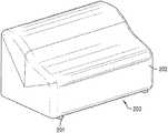
- FIG. 2depicts an example foam-film composite in accordance with the present disclosure configured as furniture covers
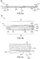
- FIGS. 3 a -3 cdepict example cross-sectional views of a foam-film composite in accordance with the present disclosure
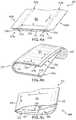
- FIGS. 4 a -4 cdepict example perspective views of another example embodiment of a foam-film composite in accordance with the present disclosure, where FIG. 4 c has been configured as a furniture cover;
- FIGS. 5 a -5 bdepict example top and cross-sectional views, respectively, of a further example embodiment of a foam-film composite in accordance with the present disclosure
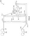
- FIG. 6is an example apparatus for making a foam-film composite in accordance with the present disclosure
- FIG. 7is an example apparatus for making furniture covers from a roll of the foam-film composites of the present disclosure
- FIG. 8is an example top view of a further example embodiment of a foam-film composite in accordance with the present disclosure divisible into two sheets;
- FIG. 9is a perspective view of another embodiment of a foam-film composite in accordance with the disclosure.
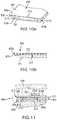
- FIGS. 10 a and bare a perspective and cutaway end view, respectively, of an embodiment of a foam-film composite with an overhanging lip;
- FIG. 11is a cross-sectional view of a flooring underlayment composite of FIG. 10 a being installed as flooring underlayment.
- a foam-film composite 300 in accordance with the present disclosuremay include a foam sheet 301 and a film sheet 302 .
- the foam sheet 301may include one or more lateral edges, for example, a first lateral edge 311 a and a second lateral edge 311 b . Lateral edges may be provided opposite one another on the sheet, and also generally parallel to one another.
- the width of the foam sheeti.e., the distance between lateral edges, may generally be between about 40 inches and 200 inches, but is preferably between about 70 inches and 115 inches, more preferably between about 100 and 110 inches. In an exemplary embodiment, the width of the foam sheet is about 106 inches.
- the thickness of the foam sheetmay generally be between about 0.01 and 0.2 inches, but is preferably between about 0.05 inches and 0.15 inches, more preferably between about 0.07 and 0.08 inches. In an exemplary embodiment, the thickness of the foam sheet is about 0.073 inches. In general, the width and thickness of the foam layer may be relatively consistent along its length, although variations of thickness and width are possible in some embodiments.
- the foam sheet 301may generally be made of any plastic material.
- the foam sheet 301is made of a polymer material, including, but not limited to, polyethylenes, polypropylenes, polyvinyls, polyurethanes, and any other polymer as may be known in the art, including combinations and mixtures thereof.
- the foam sheet 301is made of a low density polyethylene (LDPE).
- LDPElow density polyethylene
- the film sheet 302may include one or more lateral edges, for example, a first lateral edge 311 c and a second lateral edge 311 d . Lateral edges may be provided opposite one another on the sheet 302 , and also generally parallel to one another.
- the width of the film sheeti.e., the distance between lateral edges, may generally be between about 50 inches and 150 inches, but is preferably between about 90 inches and 115 inches, more preferably between about 100 and 110 inches. In an exemplary embodiment, the width of the film sheet is about 106 inches.
- the thickness of the film sheetmay generally be between about 0.0001 and 0.001 inches, but is preferably between about 0.0002 inches and 0.0007 inches, and in one embodiment between about 0.0004 and 0.0005 inches. In an exemplary embodiment, the thickness of the film sheet is 0.00045 inches. In general, the width and thickness of the film layer may be relatively consistent along its length, although variations of thickness and width are possible in some embodiments.
- the film sheet 302may generally be made of any plastic material.
- the film sheet 302is made of a polymer material, including, but not limited to, polyethylenes, polypropylenes, polyvinyls, polyurethanes, and any other polymer as may be known in the art, including combinations and mixtures thereof.
- the film sheet 302is made of a high density polyethylene (HDPE).
- HDPEhigh density polyethylene
- one or more sealsmay be provided between the film sheet 302 and the foam sheet 301 .
- a first seal 312 a between the film sheet 302 and the foam sheet 301is provided in an sealed area 310 a proximate to, but preferably not exactly at, the first lateral edge of the foam sheet 311 a and the first lateral edge of the film sheet 311 c .
- the first proximate area 310 amay generally extend along the entire longitudinal length of the film and foam sheets, although in some embodiments it may extend only part way or intermittently therealong. As also shown in FIG.
- a second seal 312 b between the film sheet 302 and the foam sheet 301is provided in an area 310 b proximate to, but not exactly at, the second lateral edge of the foam sheet 311 b and the second lateral edge of the film sheet 311 d .
- the second proximate area 310 bmay generally extend along the entire longitudinal length of the film and foam sheets, although in some embodiments it may extend only part way or intermittently therealong.
- FIG. 3 cprovides a close-up view of the second seal 312 b , the second proximate area 310 b , the second lateral edges 311 b and 311 d (arrow Z indicating the area of FIG. 3 a shown in FIG.
- the proximate areas 310 a , 310 bmay generally be between about 0.1 inches and three inches from the lateral edges, but may preferably be between about 0.5 inches and 10 inches from the lateral edges, more preferably between about 0.75 inches and 7 inches. In an exemplary embodiment, the proximate areas are provided about 5 inches from the lateral edges. While two seals are shown in the figures, it will be appreciated that more of fewer seals may be provided consistent with the present disclosure. Further, the proximate areas wherein the seals are located may be provided at consistent distances from the lateral edges, or may vary in distance along the length of the composite.
- the first and second sealsmay be positioned within about 10% of the material width from the respective first and second lateral edges of the respective material, or within about 5%. Spacings of 1%, 15%, 20%, or any percentage thereinbetween are also examples in some embodiments.
- the seals 312 a , 312 bmay generally be provided in any manner capable of adhering a film sheet to a foam sheet, including, but not limited to adhesives, tapes, glues, hot-melts, thermo or heat-sealing, thermo or heat-welding, sonic-welding, and lamination, among others.
- the sealsare provided as a hot melt glue, and preferably a PSA (pressure sensitive adhesive), such as a hot-melt PSA or another type of known PSA.
- the seals 312 a , 312 bmay generally be provided in any pattern and at any interval within the proximate areas 310 a , 310 b , including but not limited to, one or more continuous strips, one or more intermittent (discontinuous) strips, one or more dashed patterns, one or more dotted patterns, beaded patters, etc.
- the applicator that applies the adhesive to the film and/or foamcan apply a fiberized adhesive, such as in a spiral swirl or random fiber pattern, for example as described in U.S. Pat. Nos. 5,902,540; 5,882,573; and 5,904,298.
- the sealsmay also be a plurality of adjacent seal lines disposed near the foam material edge(s).
- the width of the seals (or strips thereof) 312 a , 312 b within the proximate areas 310 a , 310 bmay generally be between about 0.05 inches and 1 inch, but may preferably be between about 0.1 inches and 0.5 inches, more preferably between about 0.2 inches and 0.3 inches. In an exemplary embodiment, the seals may provided about 1 ⁇ 4 inch wide. Although the various seals provided in the composite may generally be consistent among themselves, in some embodiments, there may be variations among the type of seals, the patterns of the seals, the width of the seals, or other aspects of the configurations of the seals.
- This area 313which may generally be referred to as an “unsealed” area, may be free of any seals, lamination, or other adhesive that would hold the film sheet 302 to the foam sheet 301 .
- the film sheet 302 and the foam sheet 301may be free to separate, move, or slide relative to one another in the area 310 .
- the film and foammay thus be substantially unsealed along the entire transverse width between the first and second sealed portions near the lateral edges of the foam material.
- the lateral width of the unsealed areain some embodiments, may be above 95% of the lateral width of the foam and/or film materials, although in other embodiments, the it can be at least about 20%, 50%, or 75% thereof, for example.
- the lateral width of the unsealed portion compared to the lateral width of the sealed areasis preferably at least twice as wide, and more preferably at least 3 times, 5 times, or 10 times, or 20 times as wide.
- the sealed and unsealed areasextend continuously and preferably uninterruptedly along the entire longitudinal length of the supply material, although other embodiments may have longitudinal portions that are different, such are having a seal or perforation extending laterally thereacross.
- This relationship between the film and foam materialsmay substantially protect furniture covered with such a composite from damage, abrasions, etc.
- a piece of furniture 201is covered by a bag 202 of composite material in accordance with the present disclosure to protect the furniture 201 during storage, transport, shipping, handling, moving, etc.
- the bottom side 203 of the bag 202is open in this embodiment. Details of how the foam-film composite may be formed into a furniture bag, cover, etc. are discussed in greater detail below.
- FIG. 3 bdepicts a particular embodiment of the foam-film composite 300 that has been “C-folded” about a longitudinal axis running generally through the center of the sheets 301 , 302 .
- the C-foldindicated by reference numeral 315 , may be an arcuate bend that generally separates the composite into approximately a first half, or upper half 317 and a second half, or lower half 318 .
- halvesneed not result from the C-fold; rather, the ratio could be approximately 40%/60%, 30%/70%, 20%/80%, etc., or any range thereinbetween.
- the foam sheet 301is on the outside of the C-fold
- the film sheet 302is on the inside of the C-fold, although in some embodiments and opposite configuration may be provided.
- the film sheet 302remains free to move relative to the foam sheet in the area 310 between the seals 312 a , 312 , because there is no seal or other adhesive provided in this area 310 .
- the lateral edges 311 a - dare now near to, or adjacent one another, with an opening 340 between the first lateral edges ( 311 a , 311 c ) and the second lateral edges ( 311 b , 311 d ).
- the openingextends inward into the “C” of the C-folded composite, until the fold 315 .
- FIG. 4 ashows a perspective view of a further embodiment of a foam-film composite in accordance with the present disclosure.
- the embodiment shown hereinmay be the same in all material aspects as the foam-film composite described with regard to FIGS. 3 a -3 c above, except that the film layer may be wider than the foam layer, thereby creating one, two, or more overhang areas 425 a , 425 b at the lateral edges of the composite.
- the overhang areas 425 a , 425 bmay generally be provided between about 0.5 inches and 10 inches in length, but are preferably between about 1 inch and 8 inches, more preferably between about 4 inches and 6 inches. In an exemplary embodiment, the overhang areas 425 a , 425 b may be about 5 inches.
- FIG. 4 bdepicts an embodiment of a C-folded composite in accordance with any of the composites described above. As shown, the C-folded composite has been wound into a roll 420 along the longitudinal direction. In this configuration, at the end of the roll, the lateral edges 311 a - d are now near to, or adjacent one another, with the opening 340 between the first lateral edges ( 311 a , 311 c ) and the second lateral edges ( 311 b , 311 d ).
- the openingextends inward into the “C” of the C-folded composite, until the fold 315 .
- the first and second halvesare forced closer together, and the opening 340 substantially vanishes.
- a furniture covermay be fashioned from a C-folded composite, for example a C-folded and rolled composite roll 420 as described above with regard to FIG. 4 b .
- one or more transverse sealsmay be made in a transverse direction with respect to the C-fold, as shown by arrow B.
- a furniture cover 400is shown in FIG. 4 c with two transverse seals 431 , 432 , positioned opposite one another at a distance.
- a furniture covermay be formed as defined by: on first and second opposite sides, transverse seals 431 , 432 ; on a third side, the C-fold 315 ; on a fourth side, the opening 340 defined as the opening/space between adjacent lateral edges, 311 a , 311 c and 311 b , 311 d formed when the composite is C-folded.
- the transverse sealsmay generally be provided in any manner capable of adhering a film sheet to a foam sheet, including, but not limited to adhesives, tapes, glues, hot-melts, thermo-sealing, thermo-welding, sonic-welding, and lamination, among others.
- the sealsare provided as a thermo-seal.
- a heat-sealerconfigured for providing said heat-seals may also function as a cutter, that is, it may be a heated cutting element.
- the heated cutting elementmay instantaneously make transverse cuts and seals ( 431 , 432 ), thereby separating an individual furniture cover with each such thermo-cut/seal made. That is, each transverse thermo-cut seal/seal made forms the trailing edge transverse seal (i.e., 432 in FIG. 4 c ) of one furniture cover, while simultaneously forming the leading edge transverse seal (i.e., 431 in FIG. 4 c ) of another furniture cover (that has yet to be separated from the roll 420 ).
- the first and second transverse cutsmay be made by the heated cutting element that also heat seals a first half of the foam-film sheet on one side of the longitudinal axis to a second half of the foam-film sheet on another side of the longitudinal axis while making the cut.
- transverse cutting and sealingis described herein as a single, simultaneous step due to the thermal operation of such cutter/sealer, it will be appreciated that transverse cutting and sealing may be performed in separate steps, and using other non-thermal methods of performing the same.
- a furniture cover 400 as depicted in FIG. 4 cmay be employed in connection with the protection of a piece of furniture by inserting the opening 340 over the top (or side or bottom, etc.) of a piece of furniture, so as to cover the same. That is, the opening 340 between the adjacent first and second edges may be dimensioned to allow for insertion over a piece of furniture. It will be appreciated that the distance between transverse cuts/seals may be configured with respect to the size of the piece of furniture desired to be covered, wherein larger pieces of furniture will require the cuts/seals to be spaced relatively farther apart, and wherein smaller pieces of furniture can be accommodated with the cuts/seals spaced relatively closer together.
- FIGS. 5 a and 5 bdepict a further embodiment of a foam-film composite in accordance with the present disclosure.
- This embodimentis similar in all material respects to the embodiment of FIG. 4 a , with the further specification that the seals 312 a , 312 b are each provided as two continuous strips, i.e., strips 501 a and 502 a for seal 312 a , and strips 501 b , 502 b for seal 312 b .
- Such strips 501 a , 502 a , and 501 b , 502 bare formed as continuous and substantially parallel strips proximate the lateral edges, 311 a - d .
- more or fewer stripsmay be provided at each respective seal, and each seal may differ in the number of strips provided, among other things.
- FIGS. 6 and 7disclose and described embodiments of an apparatus that may be used to make a foam-film composite sheet, and a foam-film composite furniture cover, respectively.
- an apparatus 600is provided with various structural support members 601 , which serve to support and position the various components of the apparatus and the film/foam/seal materials relative to one another. It will be appreciated that the particular configuration of support members is referenced only for purposes of illustration of the embodiment in FIG. 6 .
- one or more rolls 602 of film material 302may be provided, and one or more rolls 603 of foam material 301 may be provided.
- the film material 302 and the foam material 301may be unrolled from the rolls 602 , 603 , and conveyed by one or more rollers, 611 a , 611 b and 611 c , 611 d to an area where the separate sheets are combined into a composite sheet.
- FIG. 6shows that
- a seal materialfor example, a hot melt glue
- a dispenser 605may be applied by a dispenser 605 through a directed nozzle 606 to the proximate areas 310 a , 310 of the foam sheet 301 , thereby creating seals 312 a , 312 when the foam sheet 301 comes into aligned contact with the film sheet 302 .
- Such aligned contactmay be provided through the operation of one or more adjacent rollers 612 a , 612 b , which may be configured to bring the foam sheet 301 a in proximate contact with the film sheet 301 b , thereby allowing the seals 312 a , 312 b to seal the two said sheets together.
- the composite sheetmay be directed out of the apparatus by means of an additional roller or rollers, e.g., roller 613 as shown in FIG. 6 .
- roller 613may be driven rollers, meaning that they may be mechanically driven by a motor or by other driving means.
- the apparatusis not driven, but rather the sheets move and come in contact with one in the described manner by human force, e.g., manually pulling the sheets through the apparatus.
- an apparatus 700is provided with various structural support members 702 , which serve to support and position the various components of the apparatus and the composite sheet relative to one another. It will be appreciated that the particular configuration of support members is referenced only for purposes of illustration of the embodiment in FIG. 7 .
- one or more rolls of C-folded foam-film composite 420is provided at a source area of the apparatus.
- a roller 705which may be a driven roller, may be provided to unwind the roll 420 .
- the C-folded compositemay be fed into a cutting/sealing mechanism component 703 configured to make transverse cuts/seals, as described above.
- the cutting/sealing componentmay include a thermo-cutter/sealer 704 , operably configured to simultaneously make a transverse cut and seal through the composite, in the manner described above using heat.
- a controller 701is provided on the apparatus to control all operation aspects thereof, including speed, positioning, configuration, cutting interval, temperature of the thermo-cutter/sealer, etc.
- a completed furniture cover 400may exit the apparatus by means of rollers 706 , which may be driven rollers.
- the completed furniture covers 400may thereafter be stacked in a stack 750 , and transported or stored for future use in protecting furniture.
- a foam-film compositemay include an additional sealed portion provided on either side of a longitudinal axis running generally through the middle of, or a central portion of, or an intermediate portion of the composite.
- This intermediate sealed portionmay thus be displaced from the first and second sealed portions by at least about a fifth, quarter, third, or half, or any fraction thereinbetween, of the transverse width of the foam sheet, such that the unsealed are includes first and second unsealed areas 313 .
- the compositemay be cut longitudinally along said axis to make two sheets with film attached to the foam at areas proximate to the edge of either resultant sheet.
- a foam-film composite sheet 800has an intermediate sealed portion 810 with two seal lines 801 a , 801 b running longitudinally on either side of a central axis 805 .
- the sheet 800may be divided into approximate half-sheets 800 a , 800 b , as described above.
- FIG. 9shows an embodiment of a roll of foam-film composite in which the width of the film and foam sheets 302 , 301 are equal.
- the sealed areas 310 a,b of film and foam sheets 302 , 301are adhered to each other by several strands 902 of fiberized PSA hot melt. Although other patterns and number of strands can be used, the strands 902 are laid out in three lines in each sealed area 310 a,b in the embodiment shown.
- FIGS. 10 a,bAn embodiment of a foam-film composite 950 is shown in FIGS. 10 a,b configured and used an flooring underlayment.
- the foam sheet 301is adhered in the sealed areas 310 a,b by longitudinal rows of adhesive laid down in dots, although other patterns and sealing methods can by used.
- This embodimenthas a single overhang area 425 a that extends beyond the corresponding lateral edge 311 a of the foam sheet 301 .
- the opposite lateral edge 311 e of the film sheet 302can be collocated, such as juxtaposed, with the corresponding lateral edge of the 311 b of the foam sheet 301 , or alternatively film edge 311 e can be displaced towards the center of the foam sheet 301 or near the edge 311 a in some applications.
- the overhang 425 acan be used as a lip to lay over an adjacent foam-film composite sheet 951 and optionally includes an adhesive layer 952 on a side of the film material 302 that is attached to the foam material 301 , to attach to the adjacent sheet, as shown in FIG. 11 .
- a removable release layercan be provided on the lip adhesive 952 which can be removed before adhering to the adjacent sheet 951 .
- the adhesive on the lipcan alternatively be provided on the opposite side of the composite sheet 950 , on the side of the film material 302 or other surface of the composite 950 that faces away from the foam material 301 , for adhering to the lip of an adjacent foam-film composite sheet that is laid thereover.
- the foam-film composite sheet 950 underlaymentcan be placed on subflooring 954 , typically of concrete, either with the film facing up or down.
- the lip 425 ais laid over the adjacent foam-film composite sheet 951 and preferably adhered thereto.
- the film sheets 302can cooperatively provide a moisture barrier.
- Flooring 955for example made from hardwood, engineered flooring, or other flooring material is laid on the foam-film composite sheets 950 , 951 .
- a foam-film compositemay include an additional layer of material on a side of the foam sheet opposite the film sheet.
- Said additional layermay be a plastic material, e.g., a polymer sheet or an extrudate comprises of one or more of the various materials described above.
- Such additional layermay be attached, connected with, or otherwise adhered to the foam layer in any of the manners discussed above, e.g., thermo-sealing, laminating, adhesives, hot-melt, glue, etc.
- the word “layer” or “sheet”may refer to a single layer or sheet of material, or it may refer to multiple layers or sheets of material. Such multiple layers or sheet may be made from a single material, or a combination of materials, as described above.
- foam-film compositehas been disclosed with respect to furniture covers, e.g., when such composites are C-folded and transversely cut/sealed, it will be appreciated that there may be may other uses of such composites, including, but not limited to, other types of covers and bags, flooring covers and flooring underlayment for wood or laminated flooring for example.
- the terms “front,” “back,” “upper,” “lower,” “side” and/or other terms indicative of directionare used herein for convenience and to depict relational positions and/or directions between the parts of the embodiments. It will be appreciated that certain embodiments, or portions thereof, can also be oriented in other positions.
- the term “about”should generally be understood to refer to both the corresponding number and a range of numbers.
- all numerical ranges hereinshould be understood to include each whole integer within the range.
Landscapes
- Engineering & Computer Science (AREA)
- Mechanical Engineering (AREA)
- Laminated Bodies (AREA)
Abstract
Description
Claims (18)
Priority Applications (2)
| Application Number | Priority Date | Filing Date | Title |
|---|---|---|---|
| US15/823,261US10875257B2 (en) | 2011-04-21 | 2017-11-27 | Edge attached film-foam sheet |
| US17/135,772US11541612B2 (en) | 2011-04-21 | 2020-12-28 | Edge attached film-foam sheet |
Applications Claiming Priority (3)
| Application Number | Priority Date | Filing Date | Title |
|---|---|---|---|
| US201161477735P | 2011-04-21 | 2011-04-21 | |
| US13/453,502US9827711B2 (en) | 2011-04-21 | 2012-04-23 | Edge attached film-foam sheet |
| US15/823,261US10875257B2 (en) | 2011-04-21 | 2017-11-27 | Edge attached film-foam sheet |
Related Parent Applications (1)
| Application Number | Title | Priority Date | Filing Date |
|---|---|---|---|
| US13/453,502DivisionUS9827711B2 (en) | 2011-04-21 | 2012-04-23 | Edge attached film-foam sheet |
Related Child Applications (1)
| Application Number | Title | Priority Date | Filing Date |
|---|---|---|---|
| US17/135,772ContinuationUS11541612B2 (en) | 2011-04-21 | 2020-12-28 | Edge attached film-foam sheet |
Publications (2)
| Publication Number | Publication Date |
|---|---|
| US20180079146A1 US20180079146A1 (en) | 2018-03-22 |
| US10875257B2true US10875257B2 (en) | 2020-12-29 |
Family
ID=47741641
Family Applications (3)
| Application Number | Title | Priority Date | Filing Date |
|---|---|---|---|
| US13/453,502Active2034-10-11US9827711B2 (en) | 2011-04-21 | 2012-04-23 | Edge attached film-foam sheet |
| US15/823,261Active2032-09-06US10875257B2 (en) | 2011-04-21 | 2017-11-27 | Edge attached film-foam sheet |
| US17/135,772Active2032-04-30US11541612B2 (en) | 2011-04-21 | 2020-12-28 | Edge attached film-foam sheet |
Family Applications Before (1)
| Application Number | Title | Priority Date | Filing Date |
|---|---|---|---|
| US13/453,502Active2034-10-11US9827711B2 (en) | 2011-04-21 | 2012-04-23 | Edge attached film-foam sheet |
Family Applications After (1)
| Application Number | Title | Priority Date | Filing Date |
|---|---|---|---|
| US17/135,772Active2032-04-30US11541612B2 (en) | 2011-04-21 | 2020-12-28 | Edge attached film-foam sheet |
Country Status (1)
| Country | Link |
|---|---|
| US (3) | US9827711B2 (en) |
Families Citing this family (22)
| Publication number | Priority date | Publication date | Assignee | Title |
|---|---|---|---|---|
| US9827711B2 (en)* | 2011-04-21 | 2017-11-28 | Pregis Innovative Packaging Llc | Edge attached film-foam sheet |
| MX2015009766A (en)* | 2013-01-28 | 2015-10-29 | Armstrong World Ind Inc | Flooring underlayment and apparatus, flooring system and floor installation method using the same. |
| US9718155B2 (en) | 2014-01-20 | 2017-08-01 | Turbotec Products, Inc. | Insulated heat exchanger tube assembly and methods of making and using same |
| WO2016044767A1 (en)* | 2014-09-19 | 2016-03-24 | Chan Simon Cs | Dunnage system |
| USD806444S1 (en) | 2015-07-09 | 2018-01-02 | Treasure Garden, Inc. | Furniture cover |
| US11267595B2 (en)* | 2016-11-01 | 2022-03-08 | Pregis Innovative Packaging Llc | Automated furniture bagger and material therefor |
| US10494163B2 (en)* | 2016-12-19 | 2019-12-03 | Robert M. Hadley | Padded shipping envelope assembly and method of manufacturing same |
| JP2019006384A (en)* | 2017-06-26 | 2019-01-17 | 本田技研工業株式会社 | Washable seat cover |
| US10717583B2 (en) | 2017-09-29 | 2020-07-21 | Amazon Technologies, Inc. | Packaging products and associated material |
| US10773839B1 (en) | 2018-02-08 | 2020-09-15 | Amazon Technologies, Inc. | Methods for packaging items and preparing packaging materials |
| EP3769926A1 (en) | 2018-02-23 | 2021-01-27 | Sealed Air Corporation (US) | Foam-in-bag systems and components thereof |
| US10967995B1 (en) | 2018-03-13 | 2021-04-06 | Amazon Technologies, Inc. | Inflatable packaging materials, automated packaging systems, and related methods |
| US11084637B1 (en)* | 2018-09-28 | 2021-08-10 | Amazon Technologies, Inc. | Cushioned packaging materials, cushioned packages, and related methods |
| US11130620B1 (en)* | 2018-09-28 | 2021-09-28 | Amazon Technologies, Inc. | Cushioned packaging materials, cushioned packages, and related methods |
| US10730261B1 (en) | 2019-11-14 | 2020-08-04 | Industrial Packaging Supplies, Inc. | Multilayer protective cover including nonwoven material |
| CN115052817B (en) | 2019-12-11 | 2024-04-05 | 普里吉斯创新包装有限责任公司 | Inflatable and deflated web |
| JP2021147896A (en)* | 2020-03-19 | 2021-09-27 | 田島ルーフィング株式会社 | Floor underlay sheet, floor structure and construction method |
| MX2023000170A (en) | 2020-07-01 | 2023-04-05 | Pregis Innovative Packaging Llc | PACKAGED WITH SEALING MATERIALS THAT HAVE DIFFERENT SEALING CONDITIONS. |
| US11958277B2 (en) | 2020-07-31 | 2024-04-16 | Pregis Innovative Packaging Llc | Expandable web with in-situ combination of expansion material components |
| USD982941S1 (en)* | 2021-03-10 | 2023-04-11 | Shaoxing Versxailtex Co., Ltd. | Recliner cover |
| CN120112462A (en)* | 2022-09-22 | 2025-06-06 | 普里吉斯有限责任公司 | Packaging with multi-layer composite walls |
| US12133588B1 (en)* | 2024-05-31 | 2024-11-05 | Bicheng Qiu | Silicone shoulder pad that protects neck scratches and prevents slipping and reduces pressure on shoulders |
Citations (33)
| Publication number | Priority date | Publication date | Assignee | Title |
|---|---|---|---|---|
| US1989794A (en) | 1934-06-01 | 1935-02-05 | Crown Willamette Paper Company | Padding strip for furniture and other articles |
| US2962158A (en) | 1958-03-31 | 1960-11-29 | Joseph J Klein | Means and method of packaging articles |
| US2979836A (en) | 1959-01-07 | 1961-04-18 | Scholl Mfg Co Inc | Foot cushioning devices for use in articles of footwear |
| US3437551A (en) | 1964-09-15 | 1969-04-08 | Mobay Chemical Corp | Method of bonding thermoplastic film to polyurethane foam and product |
| US3460740A (en)* | 1967-12-22 | 1969-08-12 | Du Pont | Heat-sealable cushioning and insulating structures |
| US3669252A (en) | 1971-03-08 | 1972-06-13 | Kimberly Clark Co | Surface protection material |
| US3829343A (en)* | 1971-02-19 | 1974-08-13 | Koepp Ag | Process for laminating a foam plastics material with a sheet-like material |
| US3906128A (en) | 1971-06-09 | 1975-09-16 | Ici Ltd | Packaging with internal pile surfaces |
| US3948436A (en) | 1974-11-04 | 1976-04-06 | Packaging Industries, Inc. | Multilayer bag |
| US4087002A (en) | 1973-11-29 | 1978-05-02 | Packaging Industries, Inc. | Shipping bag |
| US4193499A (en) | 1979-04-18 | 1980-03-18 | Lookholder Theodore W | Prefabricated unitary package which when sealed and irradiated conforms closely to contents and becomes impact-absorbing |
| US4256526A (en) | 1977-08-10 | 1981-03-17 | Nordson Corporation | Method for applying a hot melt adhesive pattern to a moving substrate |
| US4620633A (en) | 1985-09-30 | 1986-11-04 | Lookholder Theodore W | Protective envelope device for packaging fragile articles |
| US4868025A (en) | 1987-08-28 | 1989-09-19 | Packaging Industries Group, Inc. | Cushioned bag and apparatus and method of making a cushioned bag |
| US5330814A (en)* | 1993-01-07 | 1994-07-19 | Fewell Takeko N | Flexible protective cover pad |
| US5386964A (en) | 1993-01-27 | 1995-02-07 | Artistic Desk Pad & Novelty Co., Inc. | Desk pad comprising a fibrous backing and a substantially smooth facing |
| US5402892A (en) | 1992-08-31 | 1995-04-04 | Burlington Consolidated Limited Incorporation | Impact resistant wrapping system |
| US5445858A (en) | 1993-06-11 | 1995-08-29 | Nwoko; Luck I. | Attenuating pad |
| US5451437A (en)* | 1993-06-21 | 1995-09-19 | Minnesota Mining And Manufacturing Company | Method and article for protecting a container that holds a fluid |
| US5508078A (en) | 1995-01-24 | 1996-04-16 | Stalnaker; Marc E. | Edge and corner guard |
| US5518802A (en) | 1989-05-31 | 1996-05-21 | Colvin; David P. | Cushioning structure |
| US5882573A (en) | 1997-09-29 | 1999-03-16 | Illinois Tool Works Inc. | Adhesive dispensing nozzles for producing partial spray patterns and method therefor |
| US5902540A (en) | 1996-10-08 | 1999-05-11 | Illinois Tool Works Inc. | Meltblowing method and apparatus |
| US5904298A (en) | 1996-10-08 | 1999-05-18 | Illinois Tool Works Inc. | Meltblowing method and system |
| US6006905A (en)* | 1998-04-16 | 1999-12-28 | Campbell, Jr.; Robert L. | Protective bag for shipment and storage of articles of equipment and method of fabricating same |
| US6652933B2 (en)* | 2000-03-16 | 2003-11-25 | Alpine Packaging Group, Inc. | Flexible insulated pouch |
| US20040171469A1 (en) | 2002-06-20 | 2004-09-02 | Maurizio Brandolini | Polypropylene/cushioned envelope |
| US6851141B2 (en) | 2003-05-28 | 2005-02-08 | Mcmahan Robert L. | Anti-fatigue mat |
| US20050109655A1 (en) | 2003-11-21 | 2005-05-26 | Vershum Raymond G. | Packaging apparatus and method |
| US7047705B2 (en) | 1997-02-11 | 2006-05-23 | Pregis Innovative Packaging Inc. | Laminate film-foam flooring composition |
| US7485358B2 (en) | 2000-12-22 | 2009-02-03 | Pregis Innovative Packaging Inc. | Subfloor |
| US7682680B2 (en) | 2006-09-30 | 2010-03-23 | Let's Gel, Inc. | Method and apparatus for fabricating an anti-fatigue mat employing multiple durometer layers |
| US20100092758A1 (en)* | 2008-08-25 | 2010-04-15 | Storopack, Inc. | Composite Air And Foam Protective Packaging |
Family Cites Families (8)
| Publication number | Priority date | Publication date | Assignee | Title |
|---|---|---|---|---|
| US4450193A (en)* | 1983-07-05 | 1984-05-22 | Raymond Staebler | Mat assembly |
| US4529641A (en)* | 1983-11-21 | 1985-07-16 | Monsanto Company | Thermoformable laminate structure |
| US5010666A (en)* | 1986-05-26 | 1991-04-30 | Plasticos Cream, S.A. | Cushioned framed article |
| US5149065A (en)* | 1989-04-28 | 1992-09-22 | Insta-Foam Products, Inc. | Foam cushion with labyrinthine side seams |
| US5027583A (en)* | 1989-07-11 | 1991-07-02 | Sealed Air Corporation | Method of forming foam cushions for packaging purposes |
| US7445833B2 (en)* | 2001-10-09 | 2008-11-04 | Ergotech Solutions, Inc. | Ergonomic floor mat |
| US9827711B2 (en)* | 2011-04-21 | 2017-11-28 | Pregis Innovative Packaging Llc | Edge attached film-foam sheet |
| US11267595B2 (en)* | 2016-11-01 | 2022-03-08 | Pregis Innovative Packaging Llc | Automated furniture bagger and material therefor |
- 2012
- 2012-04-23USUS13/453,502patent/US9827711B2/enactiveActive
- 2017
- 2017-11-27USUS15/823,261patent/US10875257B2/enactiveActive
- 2020
- 2020-12-28USUS17/135,772patent/US11541612B2/enactiveActive
Patent Citations (39)
| Publication number | Priority date | Publication date | Assignee | Title |
|---|---|---|---|---|
| US1989794A (en) | 1934-06-01 | 1935-02-05 | Crown Willamette Paper Company | Padding strip for furniture and other articles |
| US2962158A (en) | 1958-03-31 | 1960-11-29 | Joseph J Klein | Means and method of packaging articles |
| US2979836A (en) | 1959-01-07 | 1961-04-18 | Scholl Mfg Co Inc | Foot cushioning devices for use in articles of footwear |
| US3437551A (en) | 1964-09-15 | 1969-04-08 | Mobay Chemical Corp | Method of bonding thermoplastic film to polyurethane foam and product |
| US3460740A (en)* | 1967-12-22 | 1969-08-12 | Du Pont | Heat-sealable cushioning and insulating structures |
| US3829343A (en)* | 1971-02-19 | 1974-08-13 | Koepp Ag | Process for laminating a foam plastics material with a sheet-like material |
| US3669252A (en) | 1971-03-08 | 1972-06-13 | Kimberly Clark Co | Surface protection material |
| US3906128A (en) | 1971-06-09 | 1975-09-16 | Ici Ltd | Packaging with internal pile surfaces |
| US4087002A (en) | 1973-11-29 | 1978-05-02 | Packaging Industries, Inc. | Shipping bag |
| US3948436A (en) | 1974-11-04 | 1976-04-06 | Packaging Industries, Inc. | Multilayer bag |
| US4256526A (en) | 1977-08-10 | 1981-03-17 | Nordson Corporation | Method for applying a hot melt adhesive pattern to a moving substrate |
| US4193499A (en) | 1979-04-18 | 1980-03-18 | Lookholder Theodore W | Prefabricated unitary package which when sealed and irradiated conforms closely to contents and becomes impact-absorbing |
| US4193499B1 (en) | 1979-04-18 | 1993-01-19 | Sealed Air Corp | |
| US4620633A (en) | 1985-09-30 | 1986-11-04 | Lookholder Theodore W | Protective envelope device for packaging fragile articles |
| US4620633B1 (en) | 1985-09-30 | 1991-12-31 | W Lookholder Theodore | |
| US4868025A (en) | 1987-08-28 | 1989-09-19 | Packaging Industries Group, Inc. | Cushioned bag and apparatus and method of making a cushioned bag |
| US5518802A (en) | 1989-05-31 | 1996-05-21 | Colvin; David P. | Cushioning structure |
| US5402892A (en) | 1992-08-31 | 1995-04-04 | Burlington Consolidated Limited Incorporation | Impact resistant wrapping system |
| US5330814A (en)* | 1993-01-07 | 1994-07-19 | Fewell Takeko N | Flexible protective cover pad |
| US5386964A (en) | 1993-01-27 | 1995-02-07 | Artistic Desk Pad & Novelty Co., Inc. | Desk pad comprising a fibrous backing and a substantially smooth facing |
| US5445858A (en) | 1993-06-11 | 1995-08-29 | Nwoko; Luck I. | Attenuating pad |
| US5451437A (en)* | 1993-06-21 | 1995-09-19 | Minnesota Mining And Manufacturing Company | Method and article for protecting a container that holds a fluid |
| US5508078A (en) | 1995-01-24 | 1996-04-16 | Stalnaker; Marc E. | Edge and corner guard |
| US5902540A (en) | 1996-10-08 | 1999-05-11 | Illinois Tool Works Inc. | Meltblowing method and apparatus |
| US5904298A (en) | 1996-10-08 | 1999-05-18 | Illinois Tool Works Inc. | Meltblowing method and system |
| US7047705B2 (en) | 1997-02-11 | 2006-05-23 | Pregis Innovative Packaging Inc. | Laminate film-foam flooring composition |
| US5882573A (en) | 1997-09-29 | 1999-03-16 | Illinois Tool Works Inc. | Adhesive dispensing nozzles for producing partial spray patterns and method therefor |
| US6428459B2 (en)* | 1998-04-16 | 2002-08-06 | Robert L. Campbell, Jr. | Protective bag for shipment and storage of articles of equipment and method of fabricating same |
| US6189692B1 (en)* | 1998-04-16 | 2001-02-20 | Robert L. Campbell, Jr. | Protective bag for shipment and storage of articles of equipment and method of fabricating same |
| US6006905A (en)* | 1998-04-16 | 1999-12-28 | Campbell, Jr.; Robert L. | Protective bag for shipment and storage of articles of equipment and method of fabricating same |
| US6652933B2 (en)* | 2000-03-16 | 2003-11-25 | Alpine Packaging Group, Inc. | Flexible insulated pouch |
| US6776747B2 (en)* | 2000-03-16 | 2004-08-17 | Alpine Packaging Group, Inc. | Method for assembling a dual inner flexible insulated pouch |
| US7485358B2 (en) | 2000-12-22 | 2009-02-03 | Pregis Innovative Packaging Inc. | Subfloor |
| US20040171469A1 (en) | 2002-06-20 | 2004-09-02 | Maurizio Brandolini | Polypropylene/cushioned envelope |
| US6851141B2 (en) | 2003-05-28 | 2005-02-08 | Mcmahan Robert L. | Anti-fatigue mat |
| US20050109655A1 (en) | 2003-11-21 | 2005-05-26 | Vershum Raymond G. | Packaging apparatus and method |
| US7682680B2 (en) | 2006-09-30 | 2010-03-23 | Let's Gel, Inc. | Method and apparatus for fabricating an anti-fatigue mat employing multiple durometer layers |
| US20100092758A1 (en)* | 2008-08-25 | 2010-04-15 | Storopack, Inc. | Composite Air And Foam Protective Packaging |
| US8147951B2 (en)* | 2008-08-25 | 2012-04-03 | Storopack, Inc. | Composite air and foam protective packaging |
Non-Patent Citations (1)
| Title |
|---|
| Pactiv Advanced Packaging Solutions , "Furniture Protection", www.pactiv.com, 2002, 6 pages. |
Also Published As
| Publication number | Publication date |
|---|---|
| US9827711B2 (en) | 2017-11-28 |
| US20180079146A1 (en) | 2018-03-22 |
| US11541612B2 (en) | 2023-01-03 |
| US20130047560A1 (en) | 2013-02-28 |
| US20210114315A1 (en) | 2021-04-22 |
Similar Documents
| Publication | Publication Date | Title |
|---|---|---|
| US11541612B2 (en) | Edge attached film-foam sheet | |
| US10786960B2 (en) | Inflatable pouches | |
| ES2961236T3 (en) | Procedure and system to form containers | |
| US9758279B2 (en) | Side-gusset bag made of a plastic fabric composite, and method for the production thereof | |
| ES2789648T3 (en) | Container formation procedure and system | |
| EP3535199B1 (en) | Inflatable pouches | |
| US20170274613A1 (en) | Bottom fold bag and method of making same | |
| US6481889B2 (en) | Sealed enclosure, method for the manufacture thereof, and method of packaging a beverage in said enclosure | |
| US10850877B2 (en) | Package forming systems and related methods | |
| US20010043763A1 (en) | Multi-layered freezer storage bag | |
| CA3104186C (en) | Method and system for forming packages | |
| US11975504B2 (en) | Inflatable on-demand mailer pouches and associated methods | |
| US20180118407A1 (en) | Closing and opening systems, and tear tape opening systems | |
| US9963270B2 (en) | Pouch with smooth sides | |
| JP7281259B2 (en) | Product-filled outer bag, product-filled outer bag rolled or zigzag product, production method thereof, and bag supply method | |
| JP7387676B2 (en) | Bag manufacturing method | |
| JP2005225523A (en) | Method and apparatus for packing | |
| US20200048025A1 (en) | Dispenser and dispensing method for laminating pouch web material | |
| JP7117201B2 (en) | Product-filled outer bag, product-filled outer bag wound product, production method thereof, and bag supply method | |
| JP7281258B2 (en) | Outer bag with product | |
| KR102840821B1 (en) | Manufacturing method and apparatus for bag of dual structure | |
| US20120155788A1 (en) | Bag with closure mechanism mounted by contrasting adhesive materials | |
| JPS6271633A (en) | Production unit for sheet material for double layer bag |
Legal Events
| Date | Code | Title | Description |
|---|---|---|---|
| FEPP | Fee payment procedure | Free format text:ENTITY STATUS SET TO UNDISCOUNTED (ORIGINAL EVENT CODE: BIG.); ENTITY STATUS OF PATENT OWNER: LARGE ENTITY | |
| STPP | Information on status: patent application and granting procedure in general | Free format text:DOCKETED NEW CASE - READY FOR EXAMINATION | |
| AS | Assignment | Owner name:PREGIS INNOVATIVE PACKAGING, INC., ILLINOIS Free format text:ASSIGNMENT OF ASSIGNORS INTEREST;ASSIGNORS:GREEN, DARREN KEITH;WETSCH, THOMAS D.;SIGNING DATES FROM 20110414 TO 20110502;REEL/FRAME:044385/0920 Owner name:PREGIS INNOVATIVE PACKAGING LLC, ILLINOIS Free format text:CHANGE OF NAME;ASSIGNOR:PREGIS INNOVATIVE PACKAGING INC.;REEL/FRAME:044860/0108 Effective date:20141230 | |
| AS | Assignment | Owner name:OWL ROCK CAPITAL CORPORATION, AS COLLATERAL AGENT, NEW YORK Free format text:SECURITY INTEREST;ASSIGNORS:PREGIS INNOVATIVE PACKAGING INC.;PREGIS INTELLIPACK LLC;PREGIS SHARP SYSTEMS, LLC;AND OTHERS;REEL/FRAME:046593/0535 Effective date:20180713 Owner name:OWL ROCK CAPITAL CORPORATION, AS COLLATERAL AGENT, Free format text:SECURITY INTEREST;ASSIGNORS:PREGIS INNOVATIVE PACKAGING INC.;PREGIS INTELLIPACK LLC;PREGIS SHARP SYSTEMS, LLC;AND OTHERS;REEL/FRAME:046593/0535 Effective date:20180713 | |
| AS | Assignment | Owner name:CREDIT SUISSE AG, CAYMAN ISLANDS BRANCH, NEW YORK Free format text:FIRST LIEN SECURITY AGREEMENT;ASSIGNOR:PREGIS INNOVATIVE PACKAGING LLC;REEL/FRAME:049932/0377 Effective date:20190801 Owner name:OWL ROCK CAPITAL CORPORATION, AS SECOND LIEN COLLA Free format text:SECOND LIEN PATENT SECURITY AGREEMENT;ASSIGNOR:PREGIS INNOVATIVE PACKAGING LLC;REEL/FRAME:049941/0652 Effective date:20190801 Owner name:OWL ROCK CAPITAL CORPORATION, AS SECOND LIEN COLLATERAL AGENT, NEW YORK Free format text:SECOND LIEN PATENT SECURITY AGREEMENT;ASSIGNOR:PREGIS INNOVATIVE PACKAGING LLC;REEL/FRAME:049941/0652 Effective date:20190801 | |
| STPP | Information on status: patent application and granting procedure in general | Free format text:NON FINAL ACTION MAILED | |
| AS | Assignment | Owner name:FREE-FLOW PACKAGING INTERNATIONAL, INC., ILLINOIS Free format text:RELEASE BY SECURED PARTY;ASSIGNOR:OWL ROCK CAPITAL CORPORATION, AS COLLATERAL AGENT;REEL/FRAME:050993/0798 Effective date:20190801 Owner name:PREGIS INNOVATIVE PACKAGING INC., ILLINOIS Free format text:RELEASE BY SECURED PARTY;ASSIGNOR:OWL ROCK CAPITAL CORPORATION, AS COLLATERAL AGENT;REEL/FRAME:050993/0798 Effective date:20190801 Owner name:PREGIS INTELLIPACK LLC, ILLINOIS Free format text:RELEASE BY SECURED PARTY;ASSIGNOR:OWL ROCK CAPITAL CORPORATION, AS COLLATERAL AGENT;REEL/FRAME:050993/0798 Effective date:20190801 Owner name:PREGIS SHARP SYSTEMS, LLC, ILLINOIS Free format text:RELEASE BY SECURED PARTY;ASSIGNOR:OWL ROCK CAPITAL CORPORATION, AS COLLATERAL AGENT;REEL/FRAME:050993/0798 Effective date:20190801 | |
| STPP | Information on status: patent application and granting procedure in general | Free format text:FINAL REJECTION MAILED | |
| STPP | Information on status: patent application and granting procedure in general | Free format text:NOTICE OF ALLOWANCE MAILED -- APPLICATION RECEIVED IN OFFICE OF PUBLICATIONS | |
| STCF | Information on status: patent grant | Free format text:PATENTED CASE | |
| AS | Assignment | Owner name:UBS AG, STAMFORD BRANCH, AS SUCCESSOR AGENT, CONNECTICUT Free format text:ASSIGNMENT OF PATENT SECURITY INTERESTS (FIRST LIEN);ASSIGNOR:CREDIT SUISSE AG, CAYMAN ISLANDS BRANCH;REEL/FRAME:068518/0568 Effective date:20240807 | |
| AS | Assignment | Owner name:PREGIS LLC, ILLINOIS Free format text:ASSIGNMENT OF ASSIGNORS INTEREST;ASSIGNOR:PREGIS INNOVATIVE PACKAGING LLC;REEL/FRAME:070267/0742 Effective date:20241217 |