US10874782B2 - System and method for controlling the position of a levitated rotor - Google Patents
System and method for controlling the position of a levitated rotorDownload PDFInfo
- Publication number
- US10874782B2 US10874782B2US16/218,791US201816218791AUS10874782B2US 10874782 B2US10874782 B2US 10874782B2US 201816218791 AUS201816218791 AUS 201816218791AUS 10874782 B2US10874782 B2US 10874782B2
- Authority
- US
- United States
- Prior art keywords
- rotor
- impeller
- balanced position
- modifying
- phase voltages
- Prior art date
- Legal status (The legal status is an assumption and is not a legal conclusion. Google has not performed a legal analysis and makes no representation as to the accuracy of the status listed.)
- Active, expires
Links
Images


Classifications
- A—HUMAN NECESSITIES
- A61—MEDICAL OR VETERINARY SCIENCE; HYGIENE
- A61M—DEVICES FOR INTRODUCING MEDIA INTO, OR ONTO, THE BODY; DEVICES FOR TRANSDUCING BODY MEDIA OR FOR TAKING MEDIA FROM THE BODY; DEVICES FOR PRODUCING OR ENDING SLEEP OR STUPOR
- A61M60/00—Blood pumps; Devices for mechanical circulatory actuation; Balloon pumps for circulatory assistance
- A61M60/80—Constructional details other than related to driving
- A61M60/802—Constructional details other than related to driving of non-positive displacement blood pumps
- A61M60/818—Bearings
- A61M60/824—Hydrodynamic or fluid film bearings
- A61M1/1015—
- A61M1/1031—
- A61M1/1086—
- A—HUMAN NECESSITIES
- A61—MEDICAL OR VETERINARY SCIENCE; HYGIENE
- A61M—DEVICES FOR INTRODUCING MEDIA INTO, OR ONTO, THE BODY; DEVICES FOR TRANSDUCING BODY MEDIA OR FOR TAKING MEDIA FROM THE BODY; DEVICES FOR PRODUCING OR ENDING SLEEP OR STUPOR
- A61M60/00—Blood pumps; Devices for mechanical circulatory actuation; Balloon pumps for circulatory assistance
- A61M60/10—Location thereof with respect to the patient's body
- A61M60/122—Implantable pumps or pumping devices, i.e. the blood being pumped inside the patient's body
- A61M60/165—Implantable pumps or pumping devices, i.e. the blood being pumped inside the patient's body implantable in, on, or around the heart
- A61M60/178—Implantable pumps or pumping devices, i.e. the blood being pumped inside the patient's body implantable in, on, or around the heart drawing blood from a ventricle and returning the blood to the arterial system via a cannula external to the ventricle, e.g. left or right ventricular assist devices
- A—HUMAN NECESSITIES
- A61—MEDICAL OR VETERINARY SCIENCE; HYGIENE
- A61M—DEVICES FOR INTRODUCING MEDIA INTO, OR ONTO, THE BODY; DEVICES FOR TRANSDUCING BODY MEDIA OR FOR TAKING MEDIA FROM THE BODY; DEVICES FOR PRODUCING OR ENDING SLEEP OR STUPOR
- A61M60/00—Blood pumps; Devices for mechanical circulatory actuation; Balloon pumps for circulatory assistance
- A61M60/20—Type thereof
- A61M60/205—Non-positive displacement blood pumps
- A61M60/216—Non-positive displacement blood pumps including a rotating member acting on the blood, e.g. impeller
- A61M60/226—Non-positive displacement blood pumps including a rotating member acting on the blood, e.g. impeller the blood flow through the rotating member having mainly radial components
- A61M60/232—Centrifugal pumps
- A—HUMAN NECESSITIES
- A61—MEDICAL OR VETERINARY SCIENCE; HYGIENE
- A61M—DEVICES FOR INTRODUCING MEDIA INTO, OR ONTO, THE BODY; DEVICES FOR TRANSDUCING BODY MEDIA OR FOR TAKING MEDIA FROM THE BODY; DEVICES FOR PRODUCING OR ENDING SLEEP OR STUPOR
- A61M60/00—Blood pumps; Devices for mechanical circulatory actuation; Balloon pumps for circulatory assistance
- A61M60/20—Type thereof
- A61M60/205—Non-positive displacement blood pumps
- A61M60/216—Non-positive displacement blood pumps including a rotating member acting on the blood, e.g. impeller
- A61M60/237—Non-positive displacement blood pumps including a rotating member acting on the blood, e.g. impeller the blood flow through the rotating member having mainly axial components, e.g. axial flow pumps
- A—HUMAN NECESSITIES
- A61—MEDICAL OR VETERINARY SCIENCE; HYGIENE
- A61M—DEVICES FOR INTRODUCING MEDIA INTO, OR ONTO, THE BODY; DEVICES FOR TRANSDUCING BODY MEDIA OR FOR TAKING MEDIA FROM THE BODY; DEVICES FOR PRODUCING OR ENDING SLEEP OR STUPOR
- A61M60/00—Blood pumps; Devices for mechanical circulatory actuation; Balloon pumps for circulatory assistance
- A61M60/40—Details relating to driving
- A61M60/403—Details relating to driving for non-positive displacement blood pumps
- A61M60/422—Details relating to driving for non-positive displacement blood pumps the force acting on the blood contacting member being electromagnetic, e.g. using canned motor pumps
- A—HUMAN NECESSITIES
- A61—MEDICAL OR VETERINARY SCIENCE; HYGIENE
- A61M—DEVICES FOR INTRODUCING MEDIA INTO, OR ONTO, THE BODY; DEVICES FOR TRANSDUCING BODY MEDIA OR FOR TAKING MEDIA FROM THE BODY; DEVICES FOR PRODUCING OR ENDING SLEEP OR STUPOR
- A61M60/00—Blood pumps; Devices for mechanical circulatory actuation; Balloon pumps for circulatory assistance
- A61M60/50—Details relating to control
- A61M60/508—Electronic control means, e.g. for feedback regulation
- A61M60/538—Regulation using real-time blood pump operational parameter data, e.g. motor current
- A—HUMAN NECESSITIES
- A61—MEDICAL OR VETERINARY SCIENCE; HYGIENE
- A61M—DEVICES FOR INTRODUCING MEDIA INTO, OR ONTO, THE BODY; DEVICES FOR TRANSDUCING BODY MEDIA OR FOR TAKING MEDIA FROM THE BODY; DEVICES FOR PRODUCING OR ENDING SLEEP OR STUPOR
- A61M60/00—Blood pumps; Devices for mechanical circulatory actuation; Balloon pumps for circulatory assistance
- A61M60/80—Constructional details other than related to driving
- A61M60/802—Constructional details other than related to driving of non-positive displacement blood pumps
- A61M60/818—Bearings
- A61M60/82—Magnetic bearings
- A61M60/822—Magnetic bearings specially adapted for being actively controlled
- A61M1/101—
- A61M1/1012—
- A61M1/1013—
- A61M1/1017—
- A61M1/122—
- A—HUMAN NECESSITIES
- A61—MEDICAL OR VETERINARY SCIENCE; HYGIENE
- A61M—DEVICES FOR INTRODUCING MEDIA INTO, OR ONTO, THE BODY; DEVICES FOR TRANSDUCING BODY MEDIA OR FOR TAKING MEDIA FROM THE BODY; DEVICES FOR PRODUCING OR ENDING SLEEP OR STUPOR
- A61M2205/00—General characteristics of the apparatus
- A61M2205/33—Controlling, regulating or measuring
- A61M2205/3306—Optical measuring means
- A—HUMAN NECESSITIES
- A61—MEDICAL OR VETERINARY SCIENCE; HYGIENE
- A61M—DEVICES FOR INTRODUCING MEDIA INTO, OR ONTO, THE BODY; DEVICES FOR TRANSDUCING BODY MEDIA OR FOR TAKING MEDIA FROM THE BODY; DEVICES FOR PRODUCING OR ENDING SLEEP OR STUPOR
- A61M2205/00—General characteristics of the apparatus
- A61M2205/33—Controlling, regulating or measuring
- A61M2205/3317—Electromagnetic, inductive or dielectric measuring means
- A—HUMAN NECESSITIES
- A61—MEDICAL OR VETERINARY SCIENCE; HYGIENE
- A61M—DEVICES FOR INTRODUCING MEDIA INTO, OR ONTO, THE BODY; DEVICES FOR TRANSDUCING BODY MEDIA OR FOR TAKING MEDIA FROM THE BODY; DEVICES FOR PRODUCING OR ENDING SLEEP OR STUPOR
- A61M2205/00—General characteristics of the apparatus
- A61M2205/33—Controlling, regulating or measuring
- A61M2205/3331—Pressure; Flow
- A61M2205/3334—Measuring or controlling the flow rate
- A—HUMAN NECESSITIES
- A61—MEDICAL OR VETERINARY SCIENCE; HYGIENE
- A61M—DEVICES FOR INTRODUCING MEDIA INTO, OR ONTO, THE BODY; DEVICES FOR TRANSDUCING BODY MEDIA OR FOR TAKING MEDIA FROM THE BODY; DEVICES FOR PRODUCING OR ENDING SLEEP OR STUPOR
- A61M60/00—Blood pumps; Devices for mechanical circulatory actuation; Balloon pumps for circulatory assistance
- A61M60/10—Location thereof with respect to the patient's body
- A61M60/122—Implantable pumps or pumping devices, i.e. the blood being pumped inside the patient's body
- A61M60/126—Implantable pumps or pumping devices, i.e. the blood being pumped inside the patient's body implantable via, into, inside, in line, branching on, or around a blood vessel
- A61M60/148—Implantable pumps or pumping devices, i.e. the blood being pumped inside the patient's body implantable via, into, inside, in line, branching on, or around a blood vessel in line with a blood vessel using resection or like techniques, e.g. permanent endovascular heart assist devices
Definitions
- the present inventionrelates in general to rotary devices, and more specifically, to improved pumping devices and methods for their control.
- a centrifugal pumping device or mechanical circulatory assist devicefor treating patients with heart failure.
- Many types of circulatory assist devicesare available for either short term or long term support for patients having cardiovascular disease.
- a heart pump systemknown as a left ventricular assist device (LVAD) can provide long term patient support with an implantable pump associated with an externally-worn pump control unit and batteries.
- the LVADimproves circulation throughout the body by assisting the left side of the heart in pumping blood.
- Examples of LVAD systemsare the DuraHeart® LVAS system made by Terumo Heart, Inc. of Ann Arbor, Mich. and the HeartMate IITM and HeartMate IIITM systems made by Thoratec Corporation of Pleasanton, Calif.
- centrifugal pumpwith a magnetically levitated impeller to pump blood from the left ventricle to the aorta.
- the impelleris formed as the rotor of the electric motor and rotated by the rotating magnetic field from a multiphase stator such as a brushless DC motor (BLDC).
- BLDCbrushless DC motor
- the impelleris rotated to provide sufficient blood flow through the pump to the patient's systemic circulation.
- LVAD systemsutilized mechanical bearings such as ball-and-cup bearings. More recent LVADs employ non-contact bearings which levitate the impeller using hydrodynamic and/or magnetic forces. In one example, the impeller is levitated by the combination of hydrodynamic and passive magnetic forces.
- centrifugal blood pumps used as the mechanical circulatory support devicesare miniaturized to treat a broader patient population, more reliable, and with improved outcomes.
- contactless impeller suspension technologyhas been developed in several pump designs.
- the principle of this technologyis to levitate the pump impeller using one or a combination of forces from electromagnets, hydrodynamics, and permanent magnets.
- the pumpshould be hemocompatible to minimize the blood cell damage and blood clot formation.
- the bearing gap between the levitated impeller and the pump housingbecomes an important factor. A small gap may lead to the high probability of the thrombus formation in the bearing or to elevated hemolysis due to excessive shear stress. Likewise, a large gap can compromise the hydrodynamic bearing performance and the pump efficiency.
- One pump design utilizing active magnetic bearingsachieves the desired bearing gap by levitating the impeller using magnetic fields generated by electromagnetic coils.
- Another pump designlevitates the impeller using hydrodynamic thrust bearings combined with passive magnetic bearings.
- such a designusually requires a small bearing gap to provide sufficient hydrodynamic bearing stiffness to maintain impeller levitation and prevent contacts between impeller and the pump housing. Such a small gap may result in an insufficient washout and vulnerability to blood clotting thus compromising hemocompatibility.
- various aspects of the present inventionare directed to a rotary machine including a rotor within a housing and having a rotor magnetic structure; a stator on a side of the housing for generating a rotating magnetic field for applying a torque to the rotor magnetic structure; a commutator circuit for providing a plurality of phase voltages to the stator; and a controller for rotating the rotor using the commutator circuit and a vector control algorithm.
- the controlleris configured to adjust the phase voltages to modify an attractive force of the stator on the rotor magnetic structure to translate the rotor.
- the machinefurther includes a sensing circuit for determining a position of the rotor.
- the controllermay be configured to calculate successive commanded values for the phase voltages in response to determined phase currents from the sensing circuit and a variable commutation angle.
- the angle for calculating the commanded valuesmay be determined in response to a phase current characteristic and a rotational speed of the rotor.
- the rotoris levitated by a substantially constant passive magnetic field.
- the controlleris configured to move the rotor from a first balanced position to a second balanced position.
- a rotary machineincluding a rotor within a housing and having a rotor magnetic structure; a bearing mechanism for suspending the rotor in the housing in a balanced, non-contact manner; motor coils on a side of the housing for generating a magnetic field to apply a torque on the rotor magnetic structure; at least a first sensing circuit for determining a rotational and axial position of the rotor; a controller for rotating the rotor using the motor coils; and an impeller position control mechanism for adjusting a position of the impeller in the housing.
- the bearing mechanismcomprises one of a hydrodynamic bearing, magnetic bearing, or combination of the same.
- the modification of the attractive force on the rotor magnetic structure by the controllercauses the rotor to move from a first balanced position to a second balanced position.
- the sensing circuitmay include a plurality of position sensors for detecting the axial and rotational position of the rotor.
- the plurality of position sensorsmay include Hall-effect sensors.
- the plurality of position sensorsmay include optical sensors.
- the rotor magnetic structureincludes a plurality of magnetic members.
- the rotary machineis a pump. In various embodiments, the rotary machine is a blood pump. In various embodiments, the rotor is formed as an impeller.
- Various aspects of the inventionare directed to a method of operating a centrifugal pump including a stator having windings and an impeller rotating in a non-contact manner within a pump housing, the impeller including a magnetic structure, the method includes applying a first levitating force on the impeller during rotation; and using electromagnetic windings, controlling the position of the impeller in the pump housing axially and rotationally.
- the first levitating forcecomprises a passive magnetic attractive force.
- the at least second levitating forcemay include an active magnetic force created by electromagnetic coils.
- the coilsmay be driven by vector control.
- Various aspects of the inventionare directed to a method of operating a centrifugal pump including a stator having windings and an impeller rotating in a non-contact manner within a pump housing, the impeller including a magnetic structure, the method including applying a first levitating force on the impeller during rotation; and using electromagnetic windings, controlling the position of the impeller in the pump housing axially and rotationally.
- the stator windingsform the electromagnetic windings for controlling the impeller position.
- the rotation of the impelleris controlled by interaction between the magnetic structure in the impeller and AC currents in the motor stator windings.
- the axial position of the impelleris controlled by interaction between the magnetic structure in the impeller and DC currents in the motor stator windings.
- the methodincludes using the electromagnetic windings to move the impeller axially from a first predetermined position to a second predetermined within the pump housing.
- FIG. 1is a diagram of an implantable pump as one example of a rotary machine employing the present invention.
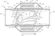
- FIG. 2is an exploded, perspective view of the exemplary centrifugal pump of FIG. 1 .
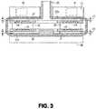
- FIG. 3is a cross-sectional view of the exemplary pump of FIG. 1 , illustrating the impeller levitated at a first balanced position generally centered within the pumping chamber in accordance with aspects of the invention.
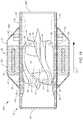
- FIG. 4is a schematic view of the exemplary pump of FIG. 1 , illustrating the impeller levitated eccentrically in the pump chamber by the main bearing components.
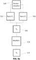
- FIG. 5is a block diagram of a pump control system in accordance with the invention.
- FIG. 6is a line chart depicting the method of controlling the impeller position in accordance with the invention.
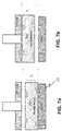
- FIG. 7 ais a schematic view of the pump of FIG. 1 , illustrating the impeller moved to another eccentric position at the bottom of the pump chamber.
- FIG. 7 bis a schematic view of the pump of FIG. 1 , illustrating the impeller moved to yet another eccentric position at the top of the pump chamber.
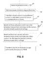
- FIG. 8is a flowchart showing a method of controlling impeller position in accordance with the invention.
- FIG. 9 ais a flowchart showing a method of controlling impeller position in accordance with the invention.
- FIG. 9 bis a line chart depicting a method for moving the impeller between two balanced positions in accordance with aspects of the invention.
- FIG. 10is a flowchart showing a method of controlling impeller position during start-up of the pump in accordance with the invention.
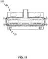
- FIG. 11is a cross-sectional view of an exemplary centrifugal flow pump in accordance with aspects of the invention, illustrating electromagnetic bearings to supplement the stator assembly positioning control.
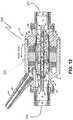
- FIG. 12is a cross-sectional view of an axial flow pump in accordance with aspects of the invention, the axial flow pump including mechanical bearings.
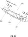
- FIG. 13is a perspective view of the impeller of FIG. 12 , with arrows depicting the direction of translation in accordance with the invention.
- FIG. 14is a cross-sectional view of another axial flow pump in accordance with aspects of the invention, the axial flow pump including mechanical bearings.
- FIG. 15is a cross-sectional view of another axial flow pump in accordance with aspects of the invention, the axial flow pump including passive magnetic and hydrodynamic bearings.
- gapgenerally refers to the secondary flow gaps around the impeller as would be understood by one of skill in the art.
- the primary flowis through the impeller blade regions.
- the secondary flow gapsare the other areas of fluid, generally around the impeller. In some respects, the secondary flow gaps are between the impeller and the housing wall and define the hydrodynamic bearing.
- machine-readable mediumincludes, but is not limited to portable or fixed storage devices, optical storage devices, wireless channels and various other mediums capable of storing, containing or carrying instructions and/or data.
- a code segment or machine-executable instructionsmay represent a procedure, a function, a subprogram, a program, a routine, a subroutine, a module, a software package, a class, or any combination of instructions, data structures, or program statements.
- a code segmentmay be coupled to another code segment or a hardware circuit by passing and/or receiving information, data, arguments, parameters, or memory contents. Information, arguments, parameters, data, etc. may be passed, forwarded, or transmitted via any suitable means including memory sharing, message passing, token passing, network transmission, etc.
- embodiments of the inventionmay be implemented, at least in part, either manually or automatically.
- Manual or automatic implementationsmay be executed, or at least assisted, through the use of machines, hardware, software, firmware, middleware, microcode, hardware description languages, or any combination thereof.
- the program code or code segments to perform the necessary tasksmay be stored in a machine readable medium.
- One or more processorsmay perform the necessary tasks.
- aspects of the inventionenable to the ability to enhance or control the bearing gap.
- Another use of the inventionmay be to increase pump efficiency.
- the motor efficiencyincreases as the impeller magnet moves closer to the motor drive coils.
- Another use of the inventionmay be to correct impeller malpositioning due to bulk forces or external forces (e.g. bumps or movements of the patient's body).
- an electromagnetic force control methodis used to change the impeller position and enhance the effective gap between the impeller and the blood chamber.
- the techniqueuses the same pump motor stator coils adjust the impeller position as is used to apply a torque to the impeller. No additional control subsystems and components are necessary.
- FIG. 1depicts an exemplary pump implanted in a heart failure patient.
- a typical cardiac assist systemincludes a pumping unit, drive electronics, microprocessor control unit, and an energy source such as rechargeable batteries and/or an AC power conditioning circuit.
- the systemis implanted during a surgical procedure in which a centrifugal pump is placed in the patient's chest.
- An inflow conduitis pierced into the left ventricle to supply blood to the pump.
- One end of an outflow conduitis mechanically fitted to the pump outlet and the other end is surgically attached to the patient's aorta by anastomosis.
- a percutaneous cableconnects to the pump, exits the patient through an incision, and connects to the external control unit.
- the exemplary systemutilizes an implantable pump with contactless bearings for supporting the impeller.
- Contactless bearingsi.e., levitation
- the impelleremploys upper and lower plates having magnetic materials (the terminology of upper and lower being arbitrary since the pump can be operated in any orientation).
- a stationary magnetic field from the upper side of the pump housingattracts the upper plate and a rotating magnetic field from the lower side of the pump housing attracts the lower plate. The forces cooperate so that the impeller rotates at a levitated position within the pumping chamber.
- the exemplary impellerhas an optimal location within the pumping chamber with a predetermined spacing from the chamber walls on each side. Maintaining a proper spacing limits the shear stress and the flow stasis of the pump.
- a high shear stresscan cause hemolysis of the blood (i.e., damage to cells).
- Flow stasiscan cause thrombosis (i.e., blood clotting).
- a patientis shown in fragmentary front elevational view.
- Surgically implanted either into the patient's abdominal cavity or pericardium 11is the pumping unit 12 of a ventricular assist device.
- An inflow conduit(on the hidden side of unit 12 ) pierces the apex of the heart to convey blood from the patient's left ventricle into pumping unit 12 .
- An outflow conduit 13conveys blood from pumping unit 12 to the patient's ascending aorta.
- a percutaneous power cable 14extends from pumping unit 12 outwardly of the patient's body via an incision to a compact control unit 15 worn by patient 10 .
- Control unit 15is powered by a main battery pack 16 and/or an external AC power supply, and an internal backup battery.
- Control unit 15includes a commutator circuit for driving a motor within pumping unit 12 .
- the commutator circuit and/or various electronicsmay be on the implanted side of the system.
- various electronicsmay be positioned on-board the pump or in a separate hermetically sealed housing.
- implanting electronicsis the ability to control the pump even when communication is lost with the control unit 15 outside the body.
- FIG. 2shows exemplary centrifugal pump unit 20 used in the system of FIG. 1 .
- the pump unit 20includes an impeller 21 and a pump housing having upper and lower halves 22 a and 22 b .
- Impeller 21is disposed within a pumping chamber 23 over a hub 24 .
- Impeller 21includes a first plate or disc 25 and a second plate or disc 27 sandwiched over a plurality of vanes 26 .
- Second disc 27includes a plurality of embedded magnet segments 44 for interacting with a levitating magnetic field created by levitation magnet structure 34 disposed against housing 22 a .
- magnet structure 34may comprise one or more permanent magnet segments providing a symmetrical, static levitation magnetic field around a 3600 circumference.
- First disc 25also contains embedded magnet segments 45 for magnetically coupling with a magnetic field from a stator assembly 35 disposed against housing 22 b .
- Housing 22 aincludes an inlet 28 for receiving blood from a patient's ventricle and distributing it to vanes 26 .
- Impeller 21is preferably circular and has an outer circumferential edge 30 . By rotatably driving impeller 21 in a pumping direction 31 , the blood received at an inner edge of impeller 21 is carried to outer circumferential 30 and enters a volute region 32 within pumping chamber 23 at an increased pressure.
- the pressurized bloodflows out from an outlet 33 formed by housing features 33 a and 33 b .
- a flow-dividing guide wall 36may be provided within volute region 32 to help stabilize the overall flow and the forces acting on impeller 21 .
- FIG. 3shows an exemplary pump 10 similar to the pump shown in FIG. 2 .
- FIG. 3shows impeller 21 located in a balanced position.
- the balanced positionsometimes refers to the position the impeller naturally stabilizes or finds equilibrium during operation.
- the balanced positionis at or near the center of the pump chamber.
- the forces acting on the impellerare generally balanced to stabilize the impeller.
- the hydrodynamic forces on the impellerwill change as the rotational speed of the impeller changes.
- the magnetic attractive forces on the impellerwill change as the impeller moves closer to or away from the magnet structure 34 and stator assembly 35 . Accordingly, the impeller generally finds a new balanced position as the rotational speed changes.
- aspects of the inventionare directed to moving the impeller or changing the balanced position for each given rotational speed.
- the impeller position control mechanisms to be describedfacilitate moving the impeller axially (up or down) without changing the rotational speed and all other. This has the effect of enabling movement of the impeller independent of rotor speed.
- An advantage of this techniqueis that rotor speed can be determined in normal course (e.g. by a physician based on the patient's physiological needs) without concern for changing the impeller position.
- the impeller positioncan be changed without affecting pumping throughput.
- FIG. 3shows impeller 21 located at or near a centered position wherein disc 27 is spaced from housing 22 A by a gap 42 and impeller disc 25 is spaced from housing 22 B by a gap 43 .
- the center positionis chosen as the balanced or balanced position to ensure substantially uniform flow through gaps 42 and 43 .
- the balanced positionis maintained by the interaction of (a) attractive magnetic forces between permanent magnets 40 and 41 in levitation magnet structure 34 with imbedded magnetic material 44 within impeller disc 27 , (b) attractive magnetic forces between stator assembly 35 and embedded magnet material 45 in impeller disc 25 , and (c) hydrodynamic bearing forces exerted by the circulating fluid which may be increased by forming hydrodynamic pressure grooves in housing 22 (not shown).
- FIG. 4shows the main structure of an exemplary centrifugal pump 50 similar to that shown in FIG. 3 . It is understood that other pump configurations may be employed, including various combinations of permanent magnets, motor stator windings, and hydrodynamic bearings.
- F a ⁇is the combined force to levitate the impeller
- F hdbis the combination of hydrodynamic forces from the inlet side bearing, the motor side bearing, or both
- F pmis the combination of permanent magnet attraction forces
- F emis the magnetic attraction force generated from the motor
- F a ⁇should be equal to zero.
- F emcan be controlled through the electronic system to adjust the impeller position since all the others are the fixed configurations as the passive mode. Therefore, the basic design concept of this invention is to apply the motor vector control (FOC) to control the force F em so that the impeller position can be adjusted while rotating only using one set of motor coil and drive system. In such way, there is no additional cost in the pump structure.
- FOCmotor vector control
- FIGS. 5 to 6illustrate a method for controlling voltages applied to a stator in order to provide a desired rotation for a permanent magnet rotor (e.g. the impeller) 52 is a field oriented control (FOC) algorithm, which is also known as vector control.
- FOCfield oriented control
- the stator magnetic fieldshould generally lead the impeller position by 90° for maximum torque efficiency.
- the magnitude of the attractive force on the impelleris proportional to the magnitude of the phase currents in the stator.
- Phase currentis adjusted by the FOC algorithm according to torque demands for the pump. Since the commutation angle is typically fixed at 90°, the resulting attractive force varies according to torque output from the pump.
- the exemplary techniquevaries the I d current which creates magnetic flux responsible for attracting the impeller. This provides a convenient and accurate mechanism to create a controlled impeller attractive force.
- modifying the commutation angle for generating the phase voltagescan change the attractive force generated by the stator thereby affecting the impeller balance.
- the impellermoves until it settles at a new balanced position where the hydrodynamic forces and magnetic forces are balanced.
- FIGS. 5, 6, 7 a , and 7 billustrate an exemplary system in accordance with aspects of the invention.
- the torque currentthat is usually called quadrature current (I q current) and stator coil flux current that is called direct current (I d current) can be decoupled and controlled independently.
- the quadrature current I q currentis used to control the impeller rotational speed.
- the direct I d currentcontrols the magnetic flux of electromagnetic coils.
- I d currentis utilized to control the impeller position by enhancing or weakening the magnetic flux between impeller (rotor) and motor stator coils to adjust the attraction force F em . This in turn changes the impeller position (shown in FIG. 6 ).
- the impeller position control techniqueis implemented as an open loop control without impeller position sensors. In one embodiment, impeller position control technique is implemented as a closed loop control with impeller position sensors.
- sensors and an adjustable magnetic sourceoccupy a significant amount of space and add to the complexity of a system. Accordingly, the use of sensors may depend on the design requirements. Suitable sensors may include, but are not limited to, Hall-effect sensors, variable reluctance sensors, and accelerometers.
- the impelleris controlled by periodically alternating the position from one side to another (e.g. from inlet side to motor side) by modulating the I d current as shown in FIG. 6 .
- the side gaps (Gap 1 and Gap 2 ) as shown in FIGS. 7 a and 7 bcan be increased or decreased.
- the position control techniquecan be implemented into the hardware and/or software of the system.
- the controllermay employ FOC to supply a multiphase voltage signal to the stator assembly 53 .
- the exemplary stator assemblyis a three-phase stator. Individual phases a, b, and c and currents I a , I b , and I c may be driven by an H-bridge inverter functioning as a commutation circuit driven by a pulse width modulator (PWM) circuit.
- PWMpulse width modulator
- An optional current sensing circuit associated with the invertermeasure instantaneous phase current in at least two phases providing current signals designated I a and I b .
- a current calculating blockreceives the two measured currents and calculates a current I c corresponding to the third phase.
- the measured currentsare input to Vector Control (FOC) block 54 and to a current observer block (not shown) which estimates the position and speed of the impeller.
- the impeller position and speedare input to the FOC block from speed control block 55 and position control block 56 .
- a target speed or revolutions per minute (rpm) for operating the pumpis provided by a conventional physiological monitor to FOC block 54 .
- the target rpmmay be set by a medical caregiver or determined according to an algorithm based on various patient parameters such heart beat, physiological needs, suction detection, and the like.
- FOC block 54 and drive electronics 57generate commanded voltage output values Va, Vb, and Vc.
- the Va, Vb, and Vc commandsmay also be coupled to the observer block for use in detecting speed and position.
- the exemplary systemdiffers from conventional configurations inasmuch as the FOC block and electronics are configured to alter the field oriented control algorithm so that a direct current (Id) can be varied independently and generate a desired attractive force.
- Iddirect current
- the inventionproceeds according to a method as shown in FIG. 8 which highlights a portion of the impeller position control with the field oriented control algorithm.
- step 65the phase currents are measured. Based on the measured phase currents, the current speed and rotor angle of the impeller are estimated in step 66 . Based on the measured rotor angle in step 66 , the phase currents are transformed into a two-axis coordinate system to generate quadrature current (I q current) and direct current (I d ) values in a rotating reference frame in step 67 . Quadrature current is used to control the torque to rotate the impeller and direct current is used to control the attraction force between rotor and stator to control the impeller position.
- I q currentquadrature current
- I ddirect current
- step 68the next quadrature voltage is determined by the quadrature current error between the quadrature current transformed from step 67 and the required current for impeller rotation.
- step 69the next direct voltage is determined by the direct current error between the direct current transformed from step 67 and the required current for the attraction force alternation to control the impeller position.
- step 70the quadrature and direct voltages are transformed back to the stationary reference frame in order to provide the multiphase voltage commands which are output to the PWM circuit.
- FIG. 9 ais a flowchart showing another method of operating a rotary machine in accordance with the invention.
- the methodincludes operating the pump to rotate the impeller by applying a rotating magnetic field in step S 10 .
- the impelleris levitated and positioned at a balanced position (P 1 ) by a balancing of forces.
- the impelleris levitated by the combination of hydrodynamic forces F 1 and other bearing forces F 2 (e.g. stator attractive force, passive magnetic forces, and/or bulk forces like gravity) in steps S 11 and S 12 .
- F 2e.g. stator attractive force, passive magnetic forces, and/or bulk forces like gravity
- the impellermoves to a new position, P 2 , where the forces are once again balanced in step S 15 .
- the impelleris moved from the first balanced position (P 1 ) to the second balanced position (P 2 ) by applying an attractive force or modifying (increasing or decreasing) an existing attractive force on the impeller.
- the attractive force modulationis substantially continuously applied to hold the impeller in the second balanced position.
- the attractive force modulationis applied periodically (e.g. as pulses) to hold the impeller in the second balanced position.
- the attractive force modulationis applied as a single pulse to move the impeller in the second balanced position.
- the second balanced positioncan be configured so the impeller remains in the second balanced position in a stable manner even when the attractive force is removed.
- FIG. 9 billustrates an exemplary method for moving the impeller between two balanced positions in accordance with aspects of the invention.
- a permanent magnet arrangementis contemplated whereby the two balanced positions are naturally a product of the permanent magnet arrangement, so that the above-mentioned attractive force modulation may not necessarily be needed or required to hold the impeller in a particular balanced position. Rather, a single (or series) pulse may be applied to “push” the impeller from one stable position to another.
- the impelleris initially, at a time t 1 , at a stable balanced position A.
- a pulse of duration(t 3 ⁇ t 2 ) is applied to push the impeller to a new, stable balanced position B.
- the impellermay be pushed between stable balanced position A and stable balanced position B in a manner as needed or desired, such as shown in FIG. 9 b .
- such an implementationmay save energy and improve pump efficiency.
- one of the two stable positionsmay be relatively close to the inlet of the above mentioned centrifugal pump unit, and another relatively close to the motor.
- the impeller position control techniqueis used to facilitate start-up of the pump.
- the exemplary pumpis configured so the impeller rests against the inlet side (top of the housing) when the impeller is not rotating.
- the impellerIn a typical pump with hydrodynamic forces alone, or in combination with magnetic forces, the impeller is levitated away from the wall as it rotates. The blood entrained in the gap between the impeller and the house creates hydrodynamic pressure; however, the impeller must be rotating at a sufficient speed to create the hydrodynamic pressure. Until the minimum speed is met, the impeller rubs against the housing wall.
- the impelleris pulled away from the wall prior to, or just after, rotation begins thereby eliminating the deleterious effects of friction.
- the impelleris pulled away from the wall by applying a force, F, as described above in step S 21 .
- the commutation anglemay be modified to exert an attractive force.
- the pumpcan be configured so the impeller rests at the inlet side. By applying an attractive force to the motor side the impeller moves down from the top wall.
- step S 22the regular start-up sequence is initiated after the impeller is removed from the wall.
- FIG. 11shows a rotary machine in accordance with another embodiment making use of electromagnets.
- Pump 100 in FIG. 11is similar in various respects to pump 10 in FIG. 3 .
- pump 100includes an active electromagnetic (EM) system 1010 .
- the EM force generated by electromagnetsis used primarily or adjunctively to move the impeller.
- Exemplary electromagnets 101comprise iron cores and windings.
- the EM forceis modified in a conventional manner by changing the current applied to the windings.
- the application of the EM forcecauses the impeller to move to position P E2 .
- the EM forcecan overpower hydrodynamic and passive magnetic forces present in the system. Accordingly, the EM structure must be dimensioned and configured to apply a relatively balanced force.
- An advantage of using electromagnets over the existing stator assemblyis that there is relatively greater positional control over the impeller.
- the phase currentstypically cannot be used as the primary variable to adjust the axial attractive force on the impeller.
- a disadvantage of this embodimentis the need to provide an entirely separate EM system. This may not be an issue with large industrial rotary machines, but many types of motors have restrictive form factors. For example, implanted pumps must be relatively small in order to address a wider patient population.
- FIGS. 12 and 13illustrate another implantable pump in accordance with the invention.
- Pump 200is similar in various respects to pumps 10 and 100 described above except pump 200 is an axial flow pump. Blood flows from in through inlet 201 and out through outlet 202 in a generally linear, axial direction.
- Pump 200includes an impeller 210 having blades for moving blood through the pump housing and imparting kinetic energy in the fluid.
- Impeller 210is fixed within the housing by ball-and-cup bearings 212 and 214 .
- the ball-and-cup bearingsare closely toleranced and generally fix the impeller in a specific position.
- the exemplary bearingsare lubricated and washed by the blood flow around the impeller. Accordingly, there is some fluid between the ball and cup surfaces.
- Torqueis applied to the impeller by a stator assembly 205 .
- the stator assembly 205includes windings and is driven using a FOC algorithm in a similar manner to the stator assemblies described above.
- the impeller positionis adjusted proceeding according to the method shown in FIG. 9 .
- the impelleris rotated in the pump housing.
- the I d currentis modulated to adjust the attractive force on the impeller in the axial direction.
- the bearing gaps of pump 200are relatively small compared to Gap 1 and Gap 2 of pump 50 in FIG. 4 . However, even relatively small impeller movement may be beneficial to enable control of the bearing gaps.
- FIG. 14illustrates another pump 300 similar to pump 200 .
- Pump 300includes an impeller fixed between two mechanical bearings 212 and 214 .
- Pump 300is slightly different than pump 200 because the outlet extends at an angle from the inlet.
- Pump 300is configured in a relatively compact design compared to pump 200 including a relatively smaller stator assembly; however, the same general principles can be applied to control the motor and adjust the impeller position.
- FIG. 15is a cross-sectional view of another pump 400 similar to pumps 200 and 300 , except pump 400 is an axial flow pump with non-contact bearings.
- Pump 400includes a pump housing having an inlet 401 and outlet 402 .
- An impeller 411is positioned within a pump chamber for imparting flow to the blood fluid within the housing.
- the impelleris entirely formed of a magnetic material which is driven by interaction with a stator assembly 405 .
- Impeller 411is stabilized in the pump chamber by a combination of hydrodynamic and passive magnetic forces.
- Impeller 411which is a magnetic material, interacts with the magnetic material in stator assembly 405 to provide an axial centering force.
- a pump ring 452 with a chamfer surfaceis positioned at the leading end of the impeller to create hydrodynamic stabilization forces in the axial direction (left to right) and radial direction (up and down on page).
- a permanent magnet ring 450is provided at the trailing edge of the impeller is oriented with a north pole facing a north pole of the impeller. This arrangement creates an axial bias force to push the impeller against the pump ring 452 .
- the magnet ring 450also provides a radially centering force.
- the impellerincludes deep hydrodynamic grooves to generate a hydrodynamic pressure force against the inner walls of the pump chamber for radial stabilization.
- the impellerIn operation, the impeller remains stable in the axial and radial directions. There may be some axial movement as the rotational speed of the impeller changes or as a result of other forces (e.g. the native pulse), but generally the impeller remains centered below the stator assembly.
- the attractive force of the stator assembly 405 on impeller 411can be modified.
- pump 400is configured so impeller is eccentric when centered below the stator assembly 405 .
- increasing the attractive forceamounts to an increase in the axial stiffness to resist axial movement.
- the attractive forceis modified to actually move impeller 411 axially.
- the impellercan be moved closer to pump ring 452 to squeeze blood out of the gap between impeller 411 and a surface of ring 452 .
- the impellermay also be moved away from ring 452 to increase the blood gap therebetween.
- the impeller position control techniqueadds an element of active position control otherwise not possible with the passive bearing configuration of pump 400 .
Landscapes
- Health & Medical Sciences (AREA)
- Heart & Thoracic Surgery (AREA)
- Engineering & Computer Science (AREA)
- Cardiology (AREA)
- Biomedical Technology (AREA)
- Mechanical Engineering (AREA)
- Anesthesiology (AREA)
- Hematology (AREA)
- Life Sciences & Earth Sciences (AREA)
- Animal Behavior & Ethology (AREA)
- General Health & Medical Sciences (AREA)
- Public Health (AREA)
- Veterinary Medicine (AREA)
- Fluid Mechanics (AREA)
- Physics & Mathematics (AREA)
- External Artificial Organs (AREA)
- Structures Of Non-Positive Displacement Pumps (AREA)
Abstract
Description
FaΣ=Fhdb+Fpm+Fem
Claims (19)
Priority Applications (3)
| Application Number | Priority Date | Filing Date | Title |
|---|---|---|---|
| US16/218,791US10874782B2 (en) | 2015-02-12 | 2018-12-13 | System and method for controlling the position of a levitated rotor |
| US17/135,416US11724097B2 (en) | 2015-02-12 | 2020-12-28 | System and method for controlling the position of a levitated rotor |
| US18/216,861US12285598B2 (en) | 2015-02-12 | 2023-06-30 | System and method for controlling the position of a levitated rotor |
Applications Claiming Priority (4)
| Application Number | Priority Date | Filing Date | Title |
|---|---|---|---|
| US201562115603P | 2015-02-12 | 2015-02-12 | |
| US201562115324P | 2015-02-12 | 2015-02-12 | |
| US15/042,431US10166318B2 (en) | 2015-02-12 | 2016-02-12 | System and method for controlling the position of a levitated rotor |
| US16/218,791US10874782B2 (en) | 2015-02-12 | 2018-12-13 | System and method for controlling the position of a levitated rotor |
Related Parent Applications (1)
| Application Number | Title | Priority Date | Filing Date |
|---|---|---|---|
| US15/042,431ContinuationUS10166318B2 (en) | 2015-02-12 | 2016-02-12 | System and method for controlling the position of a levitated rotor |
Related Child Applications (1)
| Application Number | Title | Priority Date | Filing Date |
|---|---|---|---|
| US17/135,416ContinuationUS11724097B2 (en) | 2015-02-12 | 2020-12-28 | System and method for controlling the position of a levitated rotor |
Publications (2)
| Publication Number | Publication Date |
|---|---|
| US20190184079A1 US20190184079A1 (en) | 2019-06-20 |
| US10874782B2true US10874782B2 (en) | 2020-12-29 |
Family
ID=56614941
Family Applications (4)
| Application Number | Title | Priority Date | Filing Date |
|---|---|---|---|
| US15/042,431Expired - Fee RelatedUS10166318B2 (en) | 2015-02-12 | 2016-02-12 | System and method for controlling the position of a levitated rotor |
| US16/218,791Active2036-04-01US10874782B2 (en) | 2015-02-12 | 2018-12-13 | System and method for controlling the position of a levitated rotor |
| US17/135,416Active2036-05-30US11724097B2 (en) | 2015-02-12 | 2020-12-28 | System and method for controlling the position of a levitated rotor |
| US18/216,861ActiveUS12285598B2 (en) | 2015-02-12 | 2023-06-30 | System and method for controlling the position of a levitated rotor |
Family Applications Before (1)
| Application Number | Title | Priority Date | Filing Date |
|---|---|---|---|
| US15/042,431Expired - Fee RelatedUS10166318B2 (en) | 2015-02-12 | 2016-02-12 | System and method for controlling the position of a levitated rotor |
Family Applications After (2)
| Application Number | Title | Priority Date | Filing Date |
|---|---|---|---|
| US17/135,416Active2036-05-30US11724097B2 (en) | 2015-02-12 | 2020-12-28 | System and method for controlling the position of a levitated rotor |
| US18/216,861ActiveUS12285598B2 (en) | 2015-02-12 | 2023-06-30 | System and method for controlling the position of a levitated rotor |
Country Status (3)
| Country | Link |
|---|---|
| US (4) | US10166318B2 (en) |
| EP (1) | EP3256185B1 (en) |
| WO (1) | WO2016130944A1 (en) |
Cited By (1)
| Publication number | Priority date | Publication date | Assignee | Title |
|---|---|---|---|---|
| US11724097B2 (en) | 2015-02-12 | 2023-08-15 | Tc1 Llc | System and method for controlling the position of a levitated rotor |
Families Citing this family (52)
| Publication number | Priority date | Publication date | Assignee | Title |
|---|---|---|---|---|
| JP5577506B2 (en) | 2010-09-14 | 2014-08-27 | ソーラテック コーポレイション | Centrifugal pump device |
| EP2693609B1 (en) | 2011-03-28 | 2017-05-03 | Thoratec Corporation | Rotation and drive device and centrifugal pump device using same |
| EP2564771A1 (en)* | 2011-09-05 | 2013-03-06 | ECP Entwicklungsgesellschaft mbH | Medicinal product with a functional element for invasive use in the body of a patient |
| US9371826B2 (en) | 2013-01-24 | 2016-06-21 | Thoratec Corporation | Impeller position compensation using field oriented control |
| US10052420B2 (en) | 2013-04-30 | 2018-08-21 | Tc1 Llc | Heart beat identification and pump speed synchronization |
| US9744280B2 (en)* | 2014-04-15 | 2017-08-29 | Tc1 Llc | Methods for LVAD operation during communication losses |
| EP3256183B1 (en) | 2015-02-11 | 2025-08-13 | Tc1 Llc | Heart beat identification and pump speed synchronization |
| US10371152B2 (en) | 2015-02-12 | 2019-08-06 | Tc1 Llc | Alternating pump gaps |
| EP3256184B1 (en) | 2015-02-13 | 2020-04-08 | Tc1 Llc | Impeller suspension mechanism for heart pump |
| WO2016187057A1 (en) | 2015-05-15 | 2016-11-24 | Thoratec Corporation | Improved axial flow blood pump |
| EP3135933B1 (en)* | 2015-08-25 | 2019-05-01 | ReinHeart GmbH | Active magnetic bearing |
| US10117983B2 (en) | 2015-11-16 | 2018-11-06 | Tc1 Llc | Pressure/flow characteristic modification of a centrifugal pump in a ventricular assist device |
| US10166319B2 (en) | 2016-04-11 | 2019-01-01 | CorWave SA | Implantable pump system having a coaxial ventricular cannula |
| US9968720B2 (en) | 2016-04-11 | 2018-05-15 | CorWave SA | Implantable pump system having an undulating membrane |
| US20180245596A1 (en)* | 2016-07-26 | 2018-08-30 | RELIAX MOTORES SA de CV | Integrated electric motor and pump assembly |
| EP3515524B1 (en)* | 2016-09-23 | 2020-12-30 | Heartware, Inc. | Blood pump with sensors on housing surface |
| EP3600479B1 (en) | 2017-03-31 | 2024-11-06 | CorWave SA | Implantable pump system having a rectangular membrane |
| CA3066361A1 (en) | 2017-06-07 | 2018-12-13 | Shifamed Holdings, Llc | Intravascular fluid movement devices, systems, and methods of use |
| CN110997032A (en)* | 2017-08-18 | 2020-04-10 | 心脏器械股份有限公司 | Thrombus detection and removal using flexible electronic sensors and emitters |
| FR3073578B1 (en) | 2017-11-10 | 2019-12-13 | Corwave | FLUID CIRCULATOR WITH RINGING MEMBRANE |
| WO2019094963A1 (en) | 2017-11-13 | 2019-05-16 | Shifamed Holdings, Llc | Intravascular fluid movement devices, systems, and methods of use |
| US10188779B1 (en) | 2017-11-29 | 2019-01-29 | CorWave SA | Implantable pump system having an undulating membrane with improved hydraulic performance |
| WO2019112825A1 (en)* | 2017-12-05 | 2019-06-13 | Heartware, Inc. | Blood pump with impeller rinse operation |
| WO2019152363A1 (en)* | 2018-01-31 | 2019-08-08 | Heartware, Inc. | Axial blood pump with impeller rinse operation |
| CN112004563B (en) | 2018-02-01 | 2024-08-06 | 施菲姆德控股有限责任公司 | Intravascular blood pump and methods of use and manufacture |
| CN111757761B (en) | 2018-05-10 | 2024-07-12 | 心脏器械股份有限公司 | Axial flow pump pressure algorithm with field oriented control |
| US12161857B2 (en) | 2018-07-31 | 2024-12-10 | Shifamed Holdings, Llc | Intravascular blood pumps and methods of use |
| WO2020073047A1 (en) | 2018-10-05 | 2020-04-09 | Shifamed Holdings, Llc | Intravascular blood pumps and methods of use |
| CN111298221B (en)* | 2018-12-12 | 2024-08-02 | 深圳核心医疗科技股份有限公司 | Ventricular assist device |
| WO2020188453A1 (en)* | 2019-03-15 | 2020-09-24 | CorWave SA | Systems and methods for controlling an implantable blood pump |
| AU2020283518A1 (en)* | 2019-05-29 | 2022-02-10 | Abiomed, Inc. | Coil winding pattern for enhanced motor efficiency |
| WO2021011473A1 (en) | 2019-07-12 | 2021-01-21 | Shifamed Holdings, Llc | Intravascular blood pumps and methods of manufacture and use |
| US11654275B2 (en) | 2019-07-22 | 2023-05-23 | Shifamed Holdings, Llc | Intravascular blood pumps with struts and methods of use and manufacture |
| WO2021062265A1 (en) | 2019-09-25 | 2021-04-01 | Shifamed Holdings, Llc | Intravascular blood pump systems and methods of use and control thereof |
| EP4501393A3 (en) | 2019-09-25 | 2025-04-09 | Shifamed Holdings, LLC | Catheter blood pumps and collapsible pump housings |
| US12121713B2 (en) | 2019-09-25 | 2024-10-22 | Shifamed Holdings, Llc | Catheter blood pumps and collapsible blood conduits |
| WO2021096706A1 (en) | 2019-11-12 | 2021-05-20 | Fresenius Medical Care Deutschland Gmbh | Blood treatment systems |
| CN114728116A (en) | 2019-11-12 | 2022-07-08 | 费森尤斯医疗护理德国有限责任公司 | Blood treatment system |
| EP4058087A1 (en) | 2019-11-12 | 2022-09-21 | Fresenius Medical Care Deutschland GmbH | Blood treatment systems |
| EP4058088A1 (en) | 2019-11-12 | 2022-09-21 | Fresenius Medical Care Deutschland GmbH | Blood treatment systems |
| EP4058079A1 (en) | 2019-11-12 | 2022-09-21 | Fresenius Medical Care Deutschland GmbH | Blood treatment systems |
| EP4058095A1 (en) | 2019-11-12 | 2022-09-21 | Fresenius Medical Care Deutschland GmbH | Blood treatment systems |
| CN115279450B (en)* | 2019-11-21 | 2025-03-11 | 辛卡迪亚系统公司 | Next-generation total artificial heart |
| EP4072650A4 (en) | 2019-12-11 | 2024-01-10 | Shifamed Holdings, LLC | Descending aorta and vena cava blood pumps |
| RU205275U1 (en)* | 2019-12-31 | 2021-07-06 | Акционерное общество НАУЧНО-ПРОИЗВОДСТВЕННАЯ КОМПАНИЯ "ИМПУЛЬС-проект" | INTERNAL AUXILIARY CIRCULATION PUMP |
| US11191946B2 (en) | 2020-03-06 | 2021-12-07 | CorWave SA | Implantable blood pumps comprising a linear bearing |
| RU210144U1 (en)* | 2020-11-23 | 2022-03-30 | Акционерное общество НАУЧНО-ПРОИЗВОДСТВЕННАЯ КОМПАНИЯ "ИМПУЛЬС-проект" | DISC PUMP OF LEFT VENTRICULAR BYPASS TO SUPPORT MECHANICAL HEART WORK |
| AU2022243068A1 (en)* | 2021-03-26 | 2023-10-19 | Cardiobionic Pty Ltd | Blood pump with three dimensional active electromagnetic suspension |
| US11606160B1 (en) | 2022-01-10 | 2023-03-14 | X Development Llc | Power control loop for stabilization of link power |
| EP4514442A1 (en) | 2022-04-26 | 2025-03-05 | CorWave SA | Blood pumps having an encapsulated actuator |
| WO2024105583A1 (en) | 2022-11-15 | 2024-05-23 | CorWave SA | Implantable heart pump system including an improved apical connector and/or graft connector |
| US12257427B2 (en) | 2022-11-15 | 2025-03-25 | CorWave SA | Implantable heart pump systems including an improved apical connector and/or graft connector |
Citations (413)
| Publication number | Priority date | Publication date | Assignee | Title |
|---|---|---|---|---|
| US1093868A (en) | 1912-03-11 | 1914-04-21 | Henry W Jacobs | Means for forming couplings or joints. |
| US2684035A (en) | 1947-10-02 | 1954-07-20 | Philip G Kemp | Fluid pump |
| US3023334A (en) | 1959-05-25 | 1962-02-27 | Printed Motors Inc | Printed circuit armature |
| US3510229A (en) | 1968-07-23 | 1970-05-05 | Maytag Co | One-way pump |
| US3620638A (en) | 1970-08-24 | 1971-11-16 | J Arthur Kaye | Liquid propulsion device |
| US3870382A (en) | 1972-09-29 | 1975-03-11 | Philips Corp | Axial bearing |
| US3932069A (en) | 1974-12-19 | 1976-01-13 | Ford Motor Company | Variable reluctance motor pump |
| US3960468A (en) | 1946-07-16 | 1976-06-01 | The United States Of America As Represented By The United States Energy Research And Development Administration | Fluid lubricated bearing assembly |
| US4149535A (en) | 1976-05-06 | 1979-04-17 | Gist-Brocades N.V. | Catheter holding device |
| JPS589535A (en) | 1981-07-06 | 1983-01-19 | Matsushita Electric Ind Co Ltd | Wound core for axial gap type rotating electric machine |
| US4382199A (en) | 1980-11-06 | 1983-05-03 | Nu-Tech Industries, Inc. | Hydrodynamic bearing system for a brushless DC motor |
| US4392836A (en) | 1980-05-21 | 1983-07-12 | Kanto Seiki Co., Ltd. | Device for connecting speedometer to flexible shaft |
| US4434389A (en) | 1980-10-28 | 1984-02-28 | Kollmorgen Technologies Corporation | Motor with redundant windings |
| US4507048A (en) | 1979-03-16 | 1985-03-26 | Jacques Belenger | Centrifugal clinical blood pump |
| US4528485A (en) | 1982-04-13 | 1985-07-09 | General Electric Company | Electronically commutated motor, method of operating such, control circuit, laundry machine and drive therefor |
| US4540402A (en) | 1982-04-20 | 1985-09-10 | Karl Aigner | Double perfusion catheter |
| US4549860A (en) | 1983-04-04 | 1985-10-29 | Yakich Sam S | Blood pump improvements |
| JPS61293146A (en) | 1984-11-02 | 1986-12-23 | Hitachi Ltd | Axial gap type motor |
| US4645961A (en) | 1983-04-05 | 1987-02-24 | The Charles Stark Draper Laboratory, Inc. | Dynamoelectric machine having a large magnetic gap and flexible printed circuit phase winding |
| US4686982A (en) | 1985-06-19 | 1987-08-18 | John Nash | Spiral wire bearing for rotating wire drive catheter |
| US4688998A (en) | 1981-03-18 | 1987-08-25 | Olsen Don B | Magnetically suspended and rotated impellor pump apparatus and method |
| US4753221A (en) | 1986-10-22 | 1988-06-28 | Intravascular Surgical Instruments, Inc. | Blood pumping catheter and method of use |
| US4763032A (en) | 1983-11-29 | 1988-08-09 | Fraunhofer-Gesellschaft Zur Forderung Der Angewandten Forschung E.V. | Magnetic rotor bearing |
| US4769006A (en) | 1985-05-13 | 1988-09-06 | Kos Medical Technologies, Ltd. | Hydrodynamically propelled pacing catheter |
| US4779614A (en) | 1987-04-09 | 1988-10-25 | Nimbus Medical, Inc. | Magnetically suspended rotor axial flow blood pump |
| US4790843A (en) | 1986-06-16 | 1988-12-13 | Baxter Travenol Laboratories, Inc. | Prosthetic heart valve assembly |
| US4806080A (en) | 1983-07-06 | 1989-02-21 | Ebara Corporation | Pump with shaftless impeller |
| US4817586A (en) | 1987-11-24 | 1989-04-04 | Nimbus Medical, Inc. | Percutaneous bloom pump with mixed-flow output |
| US4846152A (en) | 1987-11-24 | 1989-07-11 | Nimbus Medical, Inc. | Single-stage axial flow blood pump |
| US4857781A (en) | 1988-07-13 | 1989-08-15 | Eastman Kodak Company | High-speed non-contact linear motor with magnetic levitation |
| US4888011A (en) | 1988-07-07 | 1989-12-19 | Abiomed, Inc. | Artificial heart |
| US4895557A (en) | 1987-12-07 | 1990-01-23 | Nimbus Medical, Inc. | Drive mechanism for powering intravascular blood pumps |
| US4900227A (en) | 1988-06-14 | 1990-02-13 | Thomson-Brandt-Armements | Wind power of hydraulic power machine with axial feed, radial outflow, and variable geometry vanes, and projectiles fitted with wind power or hydraulic power machines of this type |
| US4902272A (en) | 1987-06-17 | 1990-02-20 | Abiomed Cardiovascular, Inc. | Intra-arterial cardiac support system |
| US4906229A (en) | 1988-05-03 | 1990-03-06 | Nimbus Medical, Inc. | High-frequency transvalvular axisymmetric blood pump |
| US4908012A (en) | 1988-08-08 | 1990-03-13 | Nimbus Medical, Inc. | Chronic ventricular assist system |
| US4919647A (en) | 1988-10-13 | 1990-04-24 | Kensey Nash Corporation | Aortically located blood pumping catheter and method of use |
| US4930997A (en) | 1987-08-19 | 1990-06-05 | Bennett Alan N | Portable medical suction device |
| US4944722A (en) | 1989-02-23 | 1990-07-31 | Nimbus Medical, Inc. | Percutaneous axial flow blood pump |
| US4957504A (en) | 1988-12-02 | 1990-09-18 | Chardack William M | Implantable blood pump |
| US4964864A (en) | 1988-09-27 | 1990-10-23 | American Biomed, Inc. | Heart assist pump |
| US4969865A (en) | 1989-01-09 | 1990-11-13 | American Biomed, Inc. | Helifoil pump |
| US4985014A (en) | 1989-07-11 | 1991-01-15 | Orejola Wilmo C | Ventricular venting loop |
| US4995857A (en) | 1989-04-07 | 1991-02-26 | Arnold John R | Left ventricular assist device and method for temporary and permanent procedures |
| US5021048A (en) | 1989-08-04 | 1991-06-04 | Medtronic, Inc. | Blood pump drive system |
| US5078741A (en) | 1986-10-12 | 1992-01-07 | Life Extenders Corporation | Magnetically suspended and rotated rotor |
| US5092879A (en) | 1988-02-17 | 1992-03-03 | Jarvik Robert K | Intraventricular artificial hearts and methods of their surgical implantation and use |
| US5092844A (en) | 1990-04-10 | 1992-03-03 | Mayo Foundation For Medical Education And Research | Intracatheter perfusion pump apparatus and method |
| JPH0491396A (en) | 1990-07-31 | 1992-03-24 | Ntn Corp | Turbo type pump |
| US5100374A (en) | 1989-01-31 | 1992-03-31 | Aisin Seiki Kabushiki Kaisha | Apparatus for driving blood pump |
| US5106263A (en) | 1989-09-22 | 1992-04-21 | Jidosha Denki Kogyo K.K. | Centrifugal pump with high efficiency impeller |
| US5106372A (en) | 1991-05-03 | 1992-04-21 | Sherwood Medical Company | Single use syringe |
| US5106273A (en) | 1990-03-07 | 1992-04-21 | Alcatel Cit | Vacuum pump for producing a clean molecular vacuum |
| US5112202A (en) | 1990-01-31 | 1992-05-12 | Ntn Corporation | Turbo pump with magnetically supported impeller |
| JPH04148094A (en) | 1990-10-11 | 1992-05-21 | Ntn Corp | Turbo-type pump |
| US5129883A (en) | 1990-07-26 | 1992-07-14 | Michael Black | Catheter |
| US5145333A (en) | 1990-03-01 | 1992-09-08 | The Cleveland Clinic Foundation | Fluid motor driven blood pump |
| US5147186A (en) | 1989-08-04 | 1992-09-15 | Bio Medicus, Inc. | Blood pump drive system |
| US5190528A (en) | 1990-10-19 | 1993-03-02 | Boston University | Percutaneous transseptal left atrial cannulation system |
| JPH0521197U (en) | 1991-05-17 | 1993-03-19 | 株式会社荏原製作所 | Canned motor pump |
| US5201679A (en) | 1991-12-13 | 1993-04-13 | Attwood Corporation | Marine propeller with breakaway hub |
| WO1993007388A1 (en) | 1991-10-07 | 1993-04-15 | Kletschka Harold D | Fluid pump with magnetically levitated impeller |
| US5211546A (en) | 1990-05-29 | 1993-05-18 | Nu-Tech Industries, Inc. | Axial flow blood pump with hydrodynamically suspended rotor |
| US5229693A (en) | 1991-02-28 | 1993-07-20 | Kabushiki Kaisha Toshiba | Driving control apparatus for brushless motor with optimum controlled converter |
| US5275580A (en) | 1990-03-08 | 1994-01-04 | Kenji Yamazaki | Auxiliary artificial heart of the embedded-in-body type |
| JPH0614538U (en) | 1992-07-29 | 1994-02-25 | 日本ビクター株式会社 | Sliding thrust bearing structure |
| US5290227A (en) | 1992-08-06 | 1994-03-01 | Pasque Michael K | Method of implanting blood pump in ascending aorta or main pulmonary artery |
| US5290236A (en) | 1991-09-25 | 1994-03-01 | Baxter International Inc. | Low priming volume centrifugal blood pump |
| US5300112A (en) | 1992-07-14 | 1994-04-05 | Aai Corporation | Articulated heart pump |
| US5306295A (en) | 1992-04-30 | 1994-04-26 | University Of Utah Research Foundation | Electrohydraulic heart with septum mounted pump |
| US5312341A (en) | 1992-08-14 | 1994-05-17 | Wayne State University | Retaining apparatus and procedure for transseptal catheterization |
| US5313128A (en) | 1993-02-03 | 1994-05-17 | Seagate Technology, Inc. | Lead wire elimination for enclosed spindle motor |
| WO1994014226A1 (en) | 1992-12-14 | 1994-06-23 | Honeywell Inc. | Motor system with individually controlled redundant windings |
| JPH0653790U (en) | 1992-12-25 | 1994-07-22 | エヌティエヌ株式会社 | Clean pump |
| US5332374A (en) | 1992-12-30 | 1994-07-26 | Ralph Kricker | Axially coupled flat magnetic pump |
| US5346458A (en) | 1990-06-25 | 1994-09-13 | Klaus Affeld | Electrohydraulic energy converter for cardiac assist devices and artificial hearts |
| US5350283A (en) | 1991-12-04 | 1994-09-27 | Ntn Corporation | Clean pump |
| US5354331A (en) | 1992-07-15 | 1994-10-11 | Schachar Ronald A | Treatment of presbyopia and other eye disorders |
| US5360445A (en) | 1991-11-06 | 1994-11-01 | International Business Machines Corporation | Blood pump actuator |
| US5370509A (en) | 1989-05-08 | 1994-12-06 | The Cleveland Clinic Foundation | Sealless rotodynamic pump with fluid bearing |
| US5376114A (en) | 1992-10-30 | 1994-12-27 | Jarvik; Robert | Cannula pumps for temporary cardiac support and methods of their application and use |
| JPH0714220U (en) | 1993-08-18 | 1995-03-10 | アスモ株式会社 | Submerged bearing |
| JPH0742869U (en) | 1993-12-28 | 1995-08-11 | 象印マホービン株式会社 | Centrifugal pump |
| US5449342A (en) | 1991-09-30 | 1995-09-12 | Nippon Zeon Co., Ltd. | Apparatus for assisting blood circulation |
| US5478222A (en) | 1991-04-10 | 1995-12-26 | Heidelberg; Goetz | Fluid pump having a pressure sealed motor chamber |
| US5504978A (en) | 1994-07-15 | 1996-04-09 | Meyer, Iii; Harold A. | Locking clamp assembly |
| US5507629A (en) | 1994-06-17 | 1996-04-16 | Jarvik; Robert | Artificial hearts with permanent magnet bearings |
| US5519270A (en) | 1992-08-19 | 1996-05-21 | Fujitsu Limited | Spindle motor and disk drive having the same |
| US5533957A (en) | 1994-05-06 | 1996-07-09 | Trustees Of Boston University | Method of tissue retroperfusion |
| WO1996031934A1 (en) | 1995-04-03 | 1996-10-10 | Sulzer Electronics Ag | Rotary machine with an electromagnetic rotary drive |
| US5569111A (en) | 1994-10-11 | 1996-10-29 | The United States Of America As Represented By The Secretary Of The Navy | Permanent magnet torque/force transfer apparatus |
| US5575630A (en) | 1995-08-08 | 1996-11-19 | Kyocera Corporation | Blood pump having magnetic attraction |
| US5588812A (en) | 1995-04-19 | 1996-12-31 | Nimbus, Inc. | Implantable electric axial-flow blood pump |
| US5595762A (en) | 1992-11-30 | 1997-01-21 | Laboratoires Virbac | Stabilized pulverulent active agents, compositions containing them, process for obtaining them and their applications |
| US5611679A (en) | 1996-04-22 | 1997-03-18 | Eastman Kodak Company | Corrosion-resistant pump |
| US5613935A (en) | 1994-12-16 | 1997-03-25 | Jarvik; Robert | High reliability cardiac assist system |
| JPH09122228A (en) | 1995-10-27 | 1997-05-13 | Terumo Corp | Centrifugal pump drive control device and blood supply device for extracorporeal circulation blood circuit |
| US5630836A (en) | 1995-01-19 | 1997-05-20 | Vascor, Inc. | Transcutaneous energy and information transmission apparatus |
| US5643226A (en) | 1993-02-24 | 1997-07-01 | Minnesota Mining And Manufacturing | Low velocity aortic cannula |
| US5678306A (en) | 1993-11-10 | 1997-10-21 | The United States Of America As Represented By The Administrator Of The National Aeronautics And Space Administration | Method for reducing pumping damage to blood |
| WO1997042413A1 (en) | 1996-05-03 | 1997-11-13 | University Of Utah | Hybrid magnetically suspended and rotated centrifugal pumping apparatus and method |
| US5695471A (en) | 1996-02-20 | 1997-12-09 | Kriton Medical, Inc. | Sealless rotary blood pump with passive magnetic radial bearings and blood immersed axial bearings |
| US5708346A (en) | 1994-01-10 | 1998-01-13 | Sulzer Electronics Ag | Method and control apparatus for controlling an AC-machine |
| US5725357A (en) | 1995-04-03 | 1998-03-10 | Ntn Corporation | Magnetically suspended type pump |
| US5738649A (en) | 1996-04-16 | 1998-04-14 | Cardeon Corporation | Peripheral entry biventricular catheter system for providing access to the heart for cardiopulmonary surgery or for prolonged circulatory support of the heart |
| US5746575A (en) | 1993-06-25 | 1998-05-05 | Baxter International, Inc. | Blood pump as centrifugal pump |
| US5746709A (en) | 1996-04-25 | 1998-05-05 | Medtronic, Inc. | Intravascular pump and bypass assembly and method for using the same |
| US5749855A (en) | 1992-09-02 | 1998-05-12 | Reitan; Oyvind | Catheter pump |
| US5776111A (en) | 1996-11-07 | 1998-07-07 | Medical Components, Inc. | Multiple catheter assembly |
| US5795074A (en) | 1996-10-08 | 1998-08-18 | Seagate Technology, Inc. | Grooved hydrodynamic thrust bearing |
| US5800559A (en) | 1994-02-01 | 1998-09-01 | Howmedica Inc. | Coated femoral stem prosthesis |
| US5807311A (en) | 1996-11-29 | 1998-09-15 | Palestrant; Aubrey M. | Dialysis catheter having rigid and collapsible lumens and related method |
| US5814011A (en) | 1996-04-25 | 1998-09-29 | Medtronic, Inc. | Active intravascular lung |
| US5824069A (en) | 1996-09-13 | 1998-10-20 | Medtronic, Inc. | Prosthetic heart valve with suturing member having non-uniform radial width |
| US5843129A (en) | 1992-08-06 | 1998-12-01 | Electric Boat Corporation | Electrical circuit for equipment requiring redundant flow paths and method of use |
| JPH10331841A (en) | 1997-05-27 | 1998-12-15 | Sony Corp | Hydrodynamic bearing device and method of manufacturing hydrodynamic bearing device |
| US5851174A (en) | 1996-09-17 | 1998-12-22 | Robert Jarvik | Cardiac support device |
| US5853394A (en) | 1994-05-09 | 1998-12-29 | Tolkoff; Marc Joshua | Catheter |
| US5868702A (en) | 1991-07-16 | 1999-02-09 | Heartport, Inc. | System for cardiac procedures |
| US5868703A (en) | 1996-04-10 | 1999-02-09 | Endoscopic Technologies, Inc. | Multichannel catheter |
| US5890883A (en) | 1997-03-19 | 1999-04-06 | The Cleveland Clinic Foundation | Rotodynamic pump with non-circular hydrodynamic bearing journal |
| US5911685A (en) | 1996-04-03 | 1999-06-15 | Guidant Corporation | Method and apparatus for cardiac blood flow assistance |
| US5917295A (en) | 1996-01-31 | 1999-06-29 | Kaman Electromagnetics Corporation | Motor drive system having a plurality of series connected H-bridges |
| US5917297A (en) | 1996-07-25 | 1999-06-29 | Lust Antriebstechnik Gmbh | Arrangement and method for operating a magnetically suspended, electromotoric drive apparatus in the event of a mains disturbance |
| US5924975A (en) | 1995-08-30 | 1999-07-20 | International Business Machines Corporation | Linear pump |
| US5924848A (en) | 1995-06-01 | 1999-07-20 | Advanced Bionics, Inc. | Blood pump having radial vanes with enclosed magnetic drive components |
| US5928131A (en) | 1997-11-26 | 1999-07-27 | Vascor, Inc. | Magnetically suspended fluid pump and control system |
| US5938412A (en) | 1995-06-01 | 1999-08-17 | Advanced Bionics, Inc. | Blood pump having rotor with internal bore for fluid flow |
| US5941813A (en) | 1996-07-23 | 1999-08-24 | Cardiotools Herzchirurgietechnik Gmbh | Cardiac assist device |
| US5945753A (en) | 1997-02-21 | 1999-08-31 | Canon Kabushiki Kaisha | Motor |
| US5947703A (en) | 1996-01-31 | 1999-09-07 | Ntn Corporation | Centrifugal blood pump assembly |
| JPH11244377A (en) | 1998-03-03 | 1999-09-14 | Terumo Corp | Centrifugal blood pump |
| US5951263A (en) | 1995-04-19 | 1999-09-14 | Nimbus, Inc. | Implantable electric axial-flow blood pump with blood-cooled bearing |
| US5964694A (en) | 1997-04-02 | 1999-10-12 | Guidant Corporation | Method and apparatus for cardiac blood flow assistance |
| US5984892A (en) | 1996-09-16 | 1999-11-16 | Minnesota Mining And Manufacturing Company | Blood aspirator |
| US6004269A (en) | 1993-07-01 | 1999-12-21 | Boston Scientific Corporation | Catheters for imaging, sensing electrical potentials, and ablating tissue |
| US6007479A (en) | 1996-07-08 | 1999-12-28 | H.D.S. Systems Ltd. | Heart assist system and method |
| EP0971212A1 (en) | 1998-07-10 | 2000-01-12 | Sulzer Electronics AG | Method to determine the pressure loss and the flow rate through a pump |
| US6030188A (en) | 1996-05-28 | 2000-02-29 | Terumo Kabushiki Kaisha | Centrifugal blood pump assembly having magnetic material embedded in impeller vanes |
| US6042347A (en) | 1998-07-27 | 2000-03-28 | Scholl; Frank G. | Pedia-cadio pump |
| US6053705A (en) | 1996-09-10 | 2000-04-25 | Sulzer Electronics Ag | Rotary pump and process to operate it |
| US6066086A (en) | 1996-11-01 | 2000-05-23 | Nimbus, Inc. | Speed control system for implanted blood pumps |
| US6071093A (en) | 1996-10-18 | 2000-06-06 | Abiomed, Inc. | Bearingless blood pump and electronic drive system |
| US6080133A (en) | 1996-02-20 | 2000-06-27 | Kriton Medical, Inc. | Sealless rotary blood pump |
| US6082900A (en) | 1997-02-28 | 2000-07-04 | Sumitomo Electric Industries, Ltd. | Dynamic pressure pneumatic bearing structure and method of manufacturing the same |
| US6083260A (en) | 1997-07-11 | 2000-07-04 | A-Med Systems, Inc. | Reverse flow transport pump and organ stabilization apparatus including related methods |
| US6086527A (en) | 1998-04-02 | 2000-07-11 | Scimed Life Systems, Inc. | System for treating congestive heart failure |
| US6123726A (en) | 1997-07-25 | 2000-09-26 | Seiko Epson Corporation | Portable drive system for artificial heart |
| US6123659A (en) | 1999-01-26 | 2000-09-26 | Nimbus Inc. | Blood pump with profiled outflow region |
| WO2000064509A1 (en) | 1999-04-23 | 2000-11-02 | Ventrassist Pty Ltd | A rotary blood pump and control system therefor |
| US6142752A (en) | 1997-09-05 | 2000-11-07 | Ntn Corporation | Centrifugal fluid pump assembly |
| US6143025A (en) | 1996-07-29 | 2000-11-07 | Edwards Lifesciences Corporation | Suture rings for rotatable artificial heart valves |
| US6146325A (en) | 1999-06-03 | 2000-11-14 | Arrow International, Inc. | Ventricular assist device |
| US6149683A (en) | 1998-10-05 | 2000-11-21 | Kriton Medical, Inc. | Power system for an implantable heart pump |
| US6158984A (en) | 1998-12-28 | 2000-12-12 | Kriton Medical, Inc. | Rotary blood pump with ceramic members |
| US6171078B1 (en) | 1997-09-04 | 2001-01-09 | Sulzer Electronics Ag | Centrifugal pump |
| US6176822B1 (en) | 1998-03-31 | 2001-01-23 | Impella Cardiotechnik Gmbh | Intracardiac blood pump |
| US6176848B1 (en) | 1996-04-04 | 2001-01-23 | Impella Cardiotechnik Gmbh | Intravascular blood pump |
| US6190304B1 (en) | 1999-07-13 | 2001-02-20 | University Of North Texas Health Science Center At Fort Worth | Enhanced intra-aortic balloon assist device |
| US6200260B1 (en) | 1997-10-09 | 2001-03-13 | Fore Flow Corporation | Implantable heart assist system |
| US6206659B1 (en) | 1995-06-01 | 2001-03-27 | Advanced Bionics, Inc. | Magnetically driven rotor for blood pump |
| US6222290B1 (en) | 1998-08-24 | 2001-04-24 | Sulzer Electronics Ag | Sensor arrangement in an electromagnetic rotary drive and a method for the operation of a rotary drive of this kind |
| US6227797B1 (en) | 1997-09-05 | 2001-05-08 | Ventrassist Pty Ltd And University Of Technology | Rotary pump with hydrodynamically suspended impeller |
| US6227820B1 (en) | 1999-10-05 | 2001-05-08 | Robert Jarvik | Axial force null position magnetic bearing and rotary blood pumps which use them |
| US6234772B1 (en) | 1999-04-28 | 2001-05-22 | Kriton Medical, Inc. | Rotary blood pump |
| US6245007B1 (en) | 1999-01-28 | 2001-06-12 | Terumo Cardiovascular Systems Corporation | Blood pump |
| US6247892B1 (en) | 1999-07-26 | 2001-06-19 | Impsa International Inc. | Continuous flow rotary pump |
| US6249067B1 (en) | 1998-08-24 | 2001-06-19 | Sulzer Electronics Ag | Method and sensor arrangement for the determination of the radial position of a permanent magnetic rotor |
| US6254359B1 (en) | 1996-05-10 | 2001-07-03 | The United States Of America As Represented By The Administrator Of The National Aeronautics And Space Administration | Method for providing a jewel bearing for supporting a pump rotor shaft |
| EP1113117A2 (en) | 1999-12-29 | 2001-07-04 | Guido Brohlburg | Method of making a shingle roof and safety hooks for shingle roof |
| US6264635B1 (en) | 1998-12-03 | 2001-07-24 | Kriton Medical, Inc. | Active magnetic bearing system for blood pump |
| US6268675B1 (en) | 1997-06-21 | 2001-07-31 | Sulzer Electronics Ag | Magnetically journalled electrical drive |
| US6276831B1 (en) | 1999-01-06 | 2001-08-21 | Konica Corporation | Rotary apparatus with asymmetrically formed dynamic pressure generating grooves |
| US6293901B1 (en) | 1997-11-26 | 2001-09-25 | Vascor, Inc. | Magnetically suspended fluid pump and control system |
| US6295877B1 (en) | 1999-03-30 | 2001-10-02 | A-Med Systems, Inc. | Pressure sensing cannula |
| JP2001309628A (en) | 2000-04-19 | 2001-11-02 | Unisia Jecs Corp | Motor pump |
| US20010039369A1 (en) | 1999-12-14 | 2001-11-08 | Terentiev Alexandre N. | Blood pump system |
| US6320731B1 (en) | 2000-05-24 | 2001-11-20 | Electric Boat Corporation | Fault tolerant motor drive arrangement with independent phase connections and monitoring system |
| US6319231B1 (en) | 1999-02-12 | 2001-11-20 | Abiomed, Inc. | Medical connector |
| US6351048B1 (en) | 1999-06-22 | 2002-02-26 | Levitronix Llc | Electrical rotary drive |
| US6365996B2 (en) | 1995-08-18 | 2002-04-02 | Lust Antriebstechnik Gmbh | Radial active magnetic bearing apparatus and a method for operating the same |
| CN1347585A (en) | 1999-04-20 | 2002-05-01 | 于利希研究中心有限公司 | Rotor device |
| US20020051711A1 (en) | 2000-10-30 | 2002-05-02 | Ntn Corporation | Magnetically levitated pump and controlling circuit |
| US6387037B1 (en) | 1997-10-09 | 2002-05-14 | Orqis Medical Corporation | Implantable heart assist system and method of applying same |
| US20020058994A1 (en) | 2000-11-16 | 2002-05-16 | Hill J Donald | Automatic suture fixation apparatus and method for minimally invasive cardiac surgery |
| US6394769B1 (en) | 1996-05-03 | 2002-05-28 | Medquest Products, Inc. | Pump having a magnetically suspended rotor with one active control axis |
| US20020095210A1 (en) | 2001-01-16 | 2002-07-18 | Finnegan Michael T. | Heart pump graft connector and system |
| US6422990B1 (en) | 1997-11-26 | 2002-07-23 | Vascor, Inc. | Blood pump flow rate control method and apparatus utilizing multiple sensors |
| US6425007B1 (en) | 1995-06-30 | 2002-07-23 | Sun Microsystems, Inc. | Network navigation and viewing system for network management system |
| US6439845B1 (en) | 2000-03-23 | 2002-08-27 | Kidney Replacement Services, P.C. | Blood pump |
| US6447266B2 (en) | 1996-06-26 | 2002-09-10 | University Of Pittsburgh | Blood pump having a magnetically suspended rotor |
| US6447441B1 (en) | 1998-08-07 | 2002-09-10 | Cardiacassist, Inc. | Non-invasive flow indicator for a rotary blood pump |
| US6458163B1 (en) | 2000-07-11 | 2002-10-01 | Prosthetic Design, Inc. | Coupling-socket adapter assembly for a prosthetic limb |
| US6508787B2 (en) | 1995-09-26 | 2003-01-21 | Fraunhofer-Gesellschaft Zur Foerderung Der Angewandten Forschung E.V. | System for actively supporting the flow of body fluids |
| US6508777B1 (en) | 1998-05-08 | 2003-01-21 | Cardeon Corporation | Circulatory support system and method of use for isolated segmental perfusion |
| US20030023302A1 (en) | 2001-07-26 | 2003-01-30 | Riyad Moe | Sewing cuff assembly for heart valves |
| US6517315B2 (en) | 2001-05-29 | 2003-02-11 | Hewlett-Packard Company | Enhanced performance fan with the use of winglets |
| US6522093B1 (en) | 2001-08-16 | 2003-02-18 | Prolific Technology, Inc. | Method for driving a brushless DC motor |
| US20030045772A1 (en) | 2001-08-16 | 2003-03-06 | Sanford Reich | Physiological heart pump control |
| US6532964B2 (en) | 1997-07-11 | 2003-03-18 | A-Med Systems, Inc. | Pulmonary and circulatory blood flow support devices and methods for heart surgery procedures |
| US6533716B1 (en) | 1998-03-07 | 2003-03-18 | Thomas Schmitz-Rode | Self-deploying axial-flow pump introduced intravascularly for temporary cardiac support |
| US6544216B1 (en) | 1998-05-13 | 2003-04-08 | Impella Cardiotechnik Aktiengesellschaft | Intracardiac blood pump |
| US6547530B2 (en) | 2000-05-19 | 2003-04-15 | Ntn Corporation | Fluid pump apparatus |
| US6547519B2 (en) | 2001-04-13 | 2003-04-15 | Hewlett Packard Development Company, L.P. | Blower impeller apparatus with pivotable blades |
| US20030072656A1 (en) | 2001-09-25 | 2003-04-17 | Kyo Niwatsukino | Ultra-thin pump and cooling system including the pump |
| JP2003135592A (en) | 2001-11-02 | 2003-05-13 | Terumo Corp | Medical instrument, its manufacturing method, and centrifugal liquid pump |
| US6575717B2 (en) | 1999-12-27 | 2003-06-10 | Ntn Corporation | Magnetically levitated pump |
| US6589030B2 (en) | 2000-06-20 | 2003-07-08 | Ntn Corporation | Magnetically levitated pump apparatus |
| EP1327455A1 (en) | 2002-01-09 | 2003-07-16 | Terumo Kabushiki Kaisha | Centrifugal fluid pump with failure correction |
| US20030144574A1 (en) | 2001-12-19 | 2003-07-31 | Heilman Marlin S. | Method and apparatus for providing limited back-flow in a blood pump during a non-pumping state |
| US6605032B2 (en) | 1997-10-02 | 2003-08-12 | Micromed Technology, Inc. | Implantable pump system |
| US6610004B2 (en) | 1997-10-09 | 2003-08-26 | Orqis Medical Corporation | Implantable heart assist system and method of applying same |
| US20030199727A1 (en) | 2002-04-19 | 2003-10-23 | Burke David J. | Adaptive speed control for blood pump |
| US6641558B1 (en) | 1998-09-30 | 2003-11-04 | A-Med Systems, Inc. | Method and apparatus for preventing air embolisms |
| US6641378B2 (en) | 2001-11-13 | 2003-11-04 | William D. Davis | Pump with electrodynamically supported impeller |
| CN1462344A (en) | 2001-04-30 | 2003-12-17 | 柏林心脏公开股份有限公司 | Method for controlling the position of a rotating member supported by a permanent magnet |
| US20030236490A1 (en) | 2002-06-24 | 2003-12-25 | Pavel Novak | Apparatus for irrigating a body cavity with a liquid |
| US20030236488A1 (en) | 2002-06-24 | 2003-12-25 | Pavel Novak | Apparatus for irrigating a body cavity with a liquid |
| US20040007515A1 (en) | 2002-07-15 | 2004-01-15 | Geyer Frederick J. | Filter assembly having improved sealing features |
| US20040015232A1 (en) | 2002-07-16 | 2004-01-22 | Medtronic, Inc. | Suturing rings for implantable heart valve prosthesis |
| US20040024285A1 (en) | 2002-06-21 | 2004-02-05 | Helmut Muckter | Blood pump with impeller |
| US20040030381A1 (en) | 2002-07-16 | 2004-02-12 | Shu Mark C.S. | Heart valve prosthesis |
| US6692318B2 (en) | 2001-10-26 | 2004-02-17 | The Penn State Research Foundation | Mixed flow pump |
| US6698097B1 (en) | 1999-05-06 | 2004-03-02 | Sankyo Seiki Mfg. Co., Ltd. | Method for manufacturing a tool that is used to form dynamic pressure generating grooves in dynamic pressure bearing devices |
| US6709418B1 (en) | 1997-07-11 | 2004-03-23 | A-Med Systems, Inc. | Apparatus and methods for entering cavities of the body |
| US20040064012A1 (en) | 2002-09-30 | 2004-04-01 | Terumo Kabushiki Kaisha | Blood pump system |
| US6716189B1 (en) | 1996-10-04 | 2004-04-06 | United States Surgical Corporation | Circulatory support system |
| US6716157B2 (en) | 2002-02-28 | 2004-04-06 | Michael P. Goldowsky | Magnetic suspension blood pump |
| US6732501B2 (en) | 2002-06-26 | 2004-05-11 | Heartware, Inc. | Ventricular connector |
| JP2004166401A (en) | 2002-11-13 | 2004-06-10 | Matsushita Electric Ind Co Ltd | DC brushless motor and DC pump having the same |
| US6749598B1 (en) | 1999-01-11 | 2004-06-15 | Flowmedica, Inc. | Apparatus and methods for treating congestive heart disease |
| EP1430919A1 (en) | 2002-12-17 | 2004-06-23 | Terumo Kabushiki Kaisha | Centrifugal blood pump apparatus |
| US20040145337A1 (en) | 2003-01-24 | 2004-07-29 | Toshiba Internatioal Corporation | Inverter drive system |
| JP2004209240A (en) | 2002-12-17 | 2004-07-29 | Terumo Corp | Centrifugal type blood pump apparatus |
| US20040152944A1 (en) | 2000-03-27 | 2004-08-05 | Alexander Medvedev | Chronic performance control system for rotodynamic blood pumps |
| US6790171B1 (en) | 1999-03-09 | 2004-09-14 | Universitair Medisch Cenrum Utrecht | Method and device for transventricular mechanical circulatory support |
| US6794789B2 (en) | 2000-11-25 | 2004-09-21 | Impella Cardiosystems Ag | Miniature motor |
| US20040210305A1 (en) | 2002-07-16 | 2004-10-21 | Medtronic, Inc. | Suture locking assembly and method of use |
| US20040215050A1 (en) | 2002-01-07 | 2004-10-28 | Micromed Technology, Inc. | Blood pump system and method of operation |
| US6817836B2 (en) | 2002-09-10 | 2004-11-16 | Miwatec Incorporated | Methods and apparatus for controlling a continuous flow rotary blood pump |
| WO2004098677A1 (en) | 2003-05-09 | 2004-11-18 | Queensland University Of Technology | Fluid pump |
| JP2004332566A (en) | 2003-04-30 | 2004-11-25 | Yamada Seisakusho Co Ltd | Magnet pump |
| JP2004346925A (en) | 2003-05-20 | 2004-12-09 | Yoshio Yano | Device to ensure non-contact of rotating parts of non-contact pump |
| US20040263341A1 (en) | 2003-06-24 | 2004-12-30 | Enzinna Donald John | Airflow blockage detection apparatus for a permanent split-capacitor single-phase fan motor |
| US20050004418A1 (en) | 2002-01-08 | 2005-01-06 | Morello Gino F. | Method and system for detecting ventricular collapse |
| EP1495773A2 (en) | 2003-07-07 | 2005-01-12 | Terumo Corporation | Centrifugal fluid pump apparatus |
| WO2005011087A1 (en) | 2003-07-24 | 2005-02-03 | Tesma International Inc. | Electric fluid pump |
| US20050025630A1 (en) | 1999-04-23 | 2005-02-03 | Ayre Peter Joseph | Rotary blood pump and control system therefor |
| US20050043665A1 (en) | 2001-12-27 | 2005-02-24 | Luca Vinci | Equipment for controlling blood flow in an extracorporeal blood circuit |
| US6860713B2 (en) | 2002-11-27 | 2005-03-01 | Nidec Corporation | Fan with collapsible blades, redundant fan system, and related method |
| WO2005028000A1 (en) | 2003-09-18 | 2005-03-31 | Myrakelle, Llc | Rotary blood pump |
| JP2005094955A (en) | 2003-09-18 | 2005-04-07 | Toyota Central Res & Dev Lab Inc | Axial permanent magnet motor |
| US20050073273A1 (en) | 2003-10-06 | 2005-04-07 | Wavecrest Laboratories, Llc | Fault-tolerant electric motor control system |
| WO2005034312A2 (en) | 2003-10-02 | 2005-04-14 | Foster-Miller, Inc. | Rotary pump with electromagnetic lcr bearing |
| US6884210B2 (en) | 2002-06-12 | 2005-04-26 | Miwatec Incorporated | Blood pump |
| EP1526286A2 (en) | 2003-10-23 | 2005-04-27 | NTN Corporation | Magnetically levitated pump utilizing magnetic bearings |
| US20050131271A1 (en) | 2002-01-07 | 2005-06-16 | Micromed Technology Inc. | Method and system for physiologic control of an implantable blood pump |
| US20050141887A1 (en) | 2003-11-28 | 2005-06-30 | Andras Lelkes | Method for optimizing the efficiency of a motor operated under a load |
| US6926662B1 (en) | 1998-12-23 | 2005-08-09 | A-Med Systems, Inc. | Left and right side heart support |
| US20050194851A1 (en) | 2004-03-08 | 2005-09-08 | Siemens Aktiengesellschaft | Electric machine with a circuit board for wiring lines of a winding system |
| JP2005245138A (en) | 2004-02-27 | 2005-09-08 | Japan Servo Co Ltd | motor |
| US6942672B2 (en) | 2001-10-23 | 2005-09-13 | Vascor, Inc. | Method and apparatus for attaching a conduit to the heart or a blood vessel |
| US6949066B2 (en) | 2002-08-21 | 2005-09-27 | World Heart Corporation | Rotary blood pump diagnostics and cardiac output controller |
| JP2005270345A (en) | 2004-03-24 | 2005-10-06 | Terumo Corp | Centrifugal type blood pump apparatus |
| JP2005270415A (en) | 2004-03-25 | 2005-10-06 | Terumo Corp | Centrifugal type blood pump apparatus |
| JP2005287599A (en) | 2004-03-31 | 2005-10-20 | Terumo Corp | Centrifugal type blood pump apparatus |
| US6966748B2 (en) | 1997-09-05 | 2005-11-22 | Ventrassist PTY Ltd. and University of Technology at Sydney | Rotary pump with exclusively hydrodynamically suspended impeller |
| EP1598087A2 (en) | 2004-03-24 | 2005-11-23 | Terumo Kabushiki Kaisha | Blood pump apparatus |
| US20050261542A1 (en) | 2004-05-24 | 2005-11-24 | Riehl Mark E | Seizure therapy method and apparatus |
| US20060024182A1 (en) | 2004-03-18 | 2006-02-02 | Mustafa Akdis | Pump |
| US7010954B2 (en) | 2000-12-05 | 2006-03-14 | Impella Cardiosystems Ag | Method for calibrating a pressure sensor or a flow sensor at a rotary pump |
| US7011620B1 (en) | 1999-12-04 | 2006-03-14 | Impella Cardiosystems Ag | Intravascular blood pump |
| JP2006070476A (en) | 2004-08-31 | 2006-03-16 | Asahi Glass Matex Co Ltd | Roof member for station building |
| US20060055274A1 (en) | 2004-09-15 | 2006-03-16 | Lg Electronics Inc. | Stator of motor and method of manufacturing the same |
| US7022100B1 (en) | 1999-09-03 | 2006-04-04 | A-Med Systems, Inc. | Guidable intravascular blood pump and related methods |
| US7027875B2 (en) | 2000-12-01 | 2006-04-11 | Impella Cardiosystems Ag | Intravascular pump |
| US7048681B2 (en) | 2003-03-28 | 2006-05-23 | Terumo Corporation | Method and apparatus for adjusting a length of the inflow conduit on a ventricular assist device |
| US20060127227A1 (en) | 2004-04-09 | 2006-06-15 | A.O. Smith Corporation | Controller for a motor and a method of controlling the motor |
| JP2006167173A (en) | 2004-12-16 | 2006-06-29 | Terumo Corp | Centrifugal type blood pump apparatus |
| US7089059B1 (en) | 2000-11-03 | 2006-08-08 | Pless Benjamin D | Predicting susceptibility to neurological dysfunction based on measured neural electrophysiology |
| US7090401B2 (en) | 2003-01-21 | 2006-08-15 | Seagate Technology Llc | Grooving pattern for grooved fluid bearing |
| JP2006245455A (en) | 2005-03-07 | 2006-09-14 | Ricoh Co Ltd | Variable inductor |
| JP2006254619A (en) | 2005-03-11 | 2006-09-21 | Daikin Ind Ltd | Core, armature, motor, compressor, and manufacturing method thereof |
| US7112903B1 (en) | 1997-08-25 | 2006-09-26 | Levitronix Llc | Magnetically journalled rotational arrangement including a rotor for generating a unipolar bias magnetic flux |
| US7122019B1 (en) | 2000-11-28 | 2006-10-17 | Flowmedica Inc. | Intra-aortic renal drug delivery catheter |
| US7160243B2 (en) | 2004-03-25 | 2007-01-09 | Terumo Corporation | Method and system for controlling blood pump flow |
| JP2007002885A (en) | 2005-06-22 | 2007-01-11 | Aisin Takaoka Ltd | Differential gear |
| US7172551B2 (en) | 2004-04-12 | 2007-02-06 | Scimed Life Systems, Inc. | Cyclical pressure coronary assist pump |
| JP2007043821A (en) | 2005-08-03 | 2007-02-15 | Asmo Co Ltd | Motor and water pump |
| US20070073393A1 (en) | 2005-09-26 | 2007-03-29 | Abiomed, Inc. | Method and apparatus for pumping blood |
| US20070078293A1 (en) | 2005-10-05 | 2007-04-05 | Shambaugh Charles R Jr | Impeller for a rotary ventricular assist device |
| JP2007089974A (en) | 2005-09-30 | 2007-04-12 | Terumo Corp | Centrifugal blood pump apparatus |
| JP2007089972A (en) | 2005-09-30 | 2007-04-12 | Terumo Corp | Centrifugal blood pump apparatus |
| US20070095648A1 (en) | 2005-11-02 | 2007-05-03 | May Wayne A | High impedance system for generating electric fields and method of use |
| US20070114961A1 (en) | 2003-11-12 | 2007-05-24 | Johannes Schwarzkopf | Activation of an electric motor with continuous adjustment of the commutation angle |
| US20070134993A1 (en) | 2005-12-08 | 2007-06-14 | Daniel Tamez | Implant connector |
| US7241257B1 (en) | 2002-06-28 | 2007-07-10 | Abbott Cardiovascular Systems, Inc. | Devices and methods to perform minimally invasive surgeries |
| US20070189648A1 (en) | 2004-11-02 | 2007-08-16 | Hiromi Kita | Thrust dynamic pressure bearing, spindle motor using thereof, and information recording/reproducing device using the spindle motor |
| JP2007215292A (en) | 2006-02-08 | 2007-08-23 | Honda Motor Co Ltd | Method and apparatus for manufacturing motor rotor |
| US20070213690A1 (en) | 2006-03-08 | 2007-09-13 | Nickolas Phillips | Blood conduit connector |
| JP2007247489A (en) | 2006-03-15 | 2007-09-27 | Asmo Co Ltd | Motor-driven pump |
| US20070231135A1 (en) | 2006-03-31 | 2007-10-04 | Orqis Medical Corporation | Rotary Blood Pump |
| US7284956B2 (en) | 2002-09-10 | 2007-10-23 | Miwatec Co., Ltd. | Methods and apparatus for controlling a continuous flow rotary blood pump |
| US20070282298A1 (en) | 2006-04-20 | 2007-12-06 | Ventrassist Pty Ltd | System and method for controlling a rotary blood pump |
| US20070297923A1 (en) | 2006-06-23 | 2007-12-27 | Terumo Kabushiki Kaisha | Blood pump device |
| US20080007196A1 (en) | 2006-06-22 | 2008-01-10 | Daisuke Tan | Apparatus and method for driving an induction motor |
| JP2008011611A (en) | 2006-06-28 | 2008-01-17 | Victor Co Of Japan Ltd | Electric motor |
| US20080021394A1 (en) | 2006-01-13 | 2008-01-24 | Larose Jeffrey A | Stabilizing drive for contactless rotary blood pump impeller |
| US20080030895A1 (en) | 2004-05-20 | 2008-02-07 | Rikuro Obara | Fluid Dynamic Pressure Bearing, Spindle Motor and Storage Disk Drive Bearing and a Method of Manufacturing Thereof |
| US7329236B2 (en) | 1999-01-11 | 2008-02-12 | Flowmedica, Inc. | Intra-aortic renal drug delivery catheter |
| JP2008099453A (en) | 2006-10-12 | 2008-04-24 | Daikin Ind Ltd | Field element and armature core, armature and motor |
| JP2008104278A (en) | 2006-10-18 | 2008-05-01 | Honda Motor Co Ltd | motor |
| US20080124231A1 (en) | 2006-11-28 | 2008-05-29 | Terumo Kabushiki Kaisha | Sensorless Magnetic Bearing Type Blood Pump Apparatus |
| US7393181B2 (en) | 2004-09-17 | 2008-07-01 | The Penn State Research Foundation | Expandable impeller pump |
| US20080183287A1 (en) | 2002-09-30 | 2008-07-31 | Ayre Peter J | Physiological demand responsive control system |
| JP2008193838A (en) | 2007-02-06 | 2008-08-21 | Daikin Ind Ltd | Axial gap type motor |
| US20080211439A1 (en) | 2007-02-15 | 2008-09-04 | Denso Corporation | Drive device for a brushless motor |
| US7462019B1 (en) | 1998-04-22 | 2008-12-09 | Allarie Paul E | Implantable centrifugal blood pump with hybrid magnetic bearings |
| JP2008301634A (en) | 2007-05-31 | 2008-12-11 | Nidec Sankyo Corp | Motor |
| JP2008297997A (en) | 2007-05-31 | 2008-12-11 | Isamu Aotani | Pump device |
| US20090041595A1 (en) | 2007-08-07 | 2009-02-12 | Terumo Cardiovascular Systems Corporation | Extracorporeal Blood Pump with Disposable Pump Head Portion Having Magnetically Levitated Impeller |
| US7491163B2 (en) | 2001-06-06 | 2009-02-17 | Orqis Medical Corporation | Multilumen catheter for minimizing limb ischemia |
| US20090074336A1 (en) | 2007-09-13 | 2009-03-19 | Martin Engesser | Fluid dynamic bearing pattern and fluid dynamic bearing |
| US20090099406A1 (en) | 2006-10-11 | 2009-04-16 | Robert Salmonsen | Control system for a blood pump |
| US20090171136A1 (en) | 2007-12-27 | 2009-07-02 | Shambaugh Jr Charles R | VAD connector plug |
| US20090257693A1 (en) | 2008-04-13 | 2009-10-15 | Aiello Anthony J | Groove configuration for a fluid dynamic bearing |
| US20090318834A1 (en) | 2006-03-22 | 2009-12-24 | Matsushita Electric Industrial Co., Ltd. | Blood test device |
| WO2009157408A1 (en) | 2008-06-23 | 2009-12-30 | テルモ株式会社 | Blood pump apparatus |
| US7660635B1 (en) | 1996-12-19 | 2010-02-09 | Medtronic, Inc. | Medical electrical lead |
| US7699586B2 (en) | 2004-12-03 | 2010-04-20 | Heartware, Inc. | Wide blade, axial flow pump |
| JP2010133381A (en) | 2008-12-08 | 2010-06-17 | Ntn Corp | Centrifugal pump device |
| WO2010067682A1 (en) | 2008-12-08 | 2010-06-17 | Ntn株式会社 | Centrifugal pump device |
| JP2010136863A (en) | 2008-12-11 | 2010-06-24 | Ntn Corp | Centrifugal type pump apparatus |
| US20100168534A1 (en) | 2006-03-22 | 2010-07-01 | Matsushita Electric Industrial Co., Ltd. | Blood inspection device |
| US20100222634A1 (en) | 2009-02-27 | 2010-09-02 | Thoratec Corporation | Blood flow meter |
| WO2010101107A1 (en) | 2009-03-06 | 2010-09-10 | Ntn株式会社 | Centrifugal pump device |
| WO2010101082A1 (en) | 2009-03-05 | 2010-09-10 | Ntn株式会社 | Centrifugal pump device |
| US20100234835A1 (en) | 2006-03-22 | 2010-09-16 | Matsushita Electric Industrial Co., Ltd. | Laser perforation device and laser perforation method |
| JP2010209691A (en) | 2009-03-06 | 2010-09-24 | Ntn Corp | Centrifugal pump device |
| US20100256440A1 (en) | 2007-06-06 | 2010-10-07 | WorldHeart, Inc. | Implantable vad with replaceable percutaneous cable |
| US20100262039A1 (en) | 2006-03-22 | 2010-10-14 | Matsushita Electric Industrial Co., Ltd. | Blood test apparatus and method of controlling the same |
| US20100266423A1 (en) | 2009-04-16 | 2010-10-21 | Gohean Jeffrey R | System and Method for Pump with Deformable Bearing Surface |
| US7841976B2 (en) | 2006-03-23 | 2010-11-30 | Thoratec Corporation | Heart assist device with expandable impeller pump |
| US20100305692A1 (en) | 2009-05-27 | 2010-12-02 | Thomas Douglas C | Monitoring of redundant conductors |
| US7862501B2 (en) | 2006-03-23 | 2011-01-04 | Thoratec Corporation | System for preventing diastolic heart failure |
| US20110015732A1 (en) | 2008-03-25 | 2011-01-20 | Sun Medical Technology Research Corporation | Auxiliary artificial heart pump drive device and auxiliary artifical heart system |
| WO2011013483A1 (en) | 2009-07-29 | 2011-02-03 | Ntn株式会社 | Rotation drive device and centrifugal pump device |
| US7888242B2 (en) | 2007-10-29 | 2011-02-15 | Semiconductor Energy Laboratory Co., Ltd. | Formation method of single crystal semiconductor layer, formation method of crystalline semiconductor layer, formation method of polycrystalline layer, and method for manufacturing semiconductor device |
| EP2298375A1 (en) | 2008-06-11 | 2011-03-23 | Sun Medical Technology Research Corporation | Artificial heart control device, artificial heart system, and artificial heart control method |
| US7934909B2 (en) | 2001-02-16 | 2011-05-03 | Berlin Heart Gmbh | Device for axially conveying fluids |
| US20110118766A1 (en) | 2009-11-15 | 2011-05-19 | Thoratec Corporation | Attachment System, Device and Method |
| US20110118829A1 (en) | 2009-11-15 | 2011-05-19 | Thoratec Corporation | Attachment device and method |
| US20110118833A1 (en) | 2009-11-15 | 2011-05-19 | Thoratec Corporation | Attachment device and method |
| US20110160519A1 (en) | 2007-08-03 | 2011-06-30 | Andreas Arndt | Rotational pump and methods for controlling rotational pumps |
| US7972122B2 (en) | 2005-04-29 | 2011-07-05 | Heartware, Inc. | Multiple rotor, wide blade, axial flow pump |
| JP2011169166A (en) | 2010-02-16 | 2011-09-01 | Ntn Corp | Centrifugal pump device |
| US20110218383A1 (en) | 2010-03-05 | 2011-09-08 | Minnetronix Inc. | Portable controller and power source for mechanical circulation support systems |
| US8096935B2 (en) | 2006-05-09 | 2012-01-17 | Thoratec Corporation | Pulsatile control system for a rotary blood pump |
| US20120022645A1 (en) | 2010-07-22 | 2012-01-26 | Thoratec Corporation | Controlling implanted blood pumps |
| JP2012021413A (en) | 2010-07-12 | 2012-02-02 | Ntn Corp | Centrifugal pump device |
| US20120035411A1 (en) | 2006-01-13 | 2012-02-09 | Heartware, Inc. | Stabilizing drive for contactless rotary blood pump impeller |
| US8123669B2 (en) | 2005-04-16 | 2012-02-28 | Abiomed Europe Gmbh | Method for controlling a blood pump |
| WO2012036059A1 (en) | 2010-09-14 | 2012-03-22 | Ntn株式会社 | Centrifugal pump device |
| US20120078030A1 (en) | 2010-09-24 | 2012-03-29 | Kevin Bourque | Generating artificial pulse |
| WO2012040544A1 (en) | 2010-09-24 | 2012-03-29 | Thoratec Corporation | Control of circulatory assist systems |
| US8152493B2 (en) | 2007-04-30 | 2012-04-10 | Hearthware Inc. | Centrifugal rotary blood pump with impeller having a hydrodynamic thrust bearing surface |
| WO2012047550A1 (en) | 2010-10-07 | 2012-04-12 | Everheart Systems, Inc. | Cardiac support systems and methods for chronic use |
| US20120095281A1 (en) | 2010-10-13 | 2012-04-19 | Reichenbach Steven H | Pumping blood |
| US8177703B2 (en) | 2005-06-06 | 2012-05-15 | The Cleveland Clinic Foundation | Blood pump |
| US20120226350A1 (en) | 2010-12-09 | 2012-09-06 | John Rudser | Controller and power source for implantable blood pump |
| US20120243759A1 (en) | 2011-03-23 | 2012-09-27 | Toshiba Medical Systems Corporation | Image processing apparatus, x-ray ct apparatus, and image processing method |
| US20120245681A1 (en) | 2011-01-21 | 2012-09-27 | Fernando Casas | Flow estimation in a blood pump |
| US20120245680A1 (en) | 2009-04-16 | 2012-09-27 | Bivacor Pty Ltd. | Heart pump controller |
| US20120253103A1 (en) | 2011-03-30 | 2012-10-04 | Robert Jarvik Md | Centrifugal blood pumps with reverse flow washout |
| WO2012132850A1 (en) | 2011-03-28 | 2012-10-04 | Ntn株式会社 | Rotation and drive device and centrifugal pump device using same |
| US8283829B2 (en) | 2007-06-26 | 2012-10-09 | Honda Motor Co., Ltd. | Axial gap motor |
| US20130030240A1 (en) | 2011-06-27 | 2013-01-31 | Heinrich Schima | Flow estimation in a blood pump |
| EP2554191A1 (en) | 2010-03-26 | 2013-02-06 | Terumo Kabushiki Kaisha | Centrifugal blood pump device |
| US20130158521A1 (en) | 2011-12-16 | 2013-06-20 | Baxter Healthcare S.A. | Medical Tubing Connection Assembly |
| US20130178694A1 (en) | 2012-01-05 | 2013-07-11 | Terumo Kabushiki Kaisha | Apical ring for ventricular assist device |
| US20130225909A1 (en) | 2012-02-27 | 2013-08-29 | Terumo Kabushiki Kaisha | Quick-Connect Outflow Tube for Ventricular Assist Device |
| US8535211B2 (en) | 2009-07-01 | 2013-09-17 | Thoratec Corporation | Blood pump with expandable cannula |
| US20130289334A1 (en) | 2011-07-11 | 2013-10-31 | Kurt D. Badstibner | Transcutaneous power transmission and communication for implanted heart assist and other devices |
| US8585290B2 (en) | 2007-02-23 | 2013-11-19 | Minebea Co., Ltd. | Fluid dynamic bearing having pressure-generating surface patterns |
| US20130331711A1 (en) | 2012-06-09 | 2013-12-12 | Ondine Tech Inc. | Electro-medical system for neuro-muscular paralysis assessment |
| US8652024B1 (en) | 2013-01-23 | 2014-02-18 | Thoratec Corporation | Sterilizable cable system for implantable blood pump |
| US20140066690A1 (en) | 2012-08-31 | 2014-03-06 | Andre Siebenhaar | Start-up Algorithm for an Implantable Blood Pump |
| US20140066691A1 (en) | 2012-08-31 | 2014-03-06 | Andre Siebenhaar | Instability Detection Algorithm for an Implantable Blood Pump |
| US8686674B2 (en) | 2009-03-20 | 2014-04-01 | Zhongzshan Broad-Ocean Motor Co., Ltd. | Method for controlling brushless DC motor |
| US20140100413A1 (en) | 2011-01-21 | 2014-04-10 | Heartware, Inc. | Suction detection on an axial blood pump using bemf data |
| US20140107399A1 (en) | 2012-10-16 | 2014-04-17 | Scr, Inc. | Devices, systems, and methods for facilitating flow from the heart to a blood pump |
| US20140142367A1 (en) | 2005-11-04 | 2014-05-22 | Thoratec Corporation | Control systems for rotary blood pumps |
| US20140200389A1 (en) | 2013-01-16 | 2014-07-17 | Thoratec Corporation | Motor fault monitor for implantable blood pump |
| US20140205467A1 (en) | 2013-01-24 | 2014-07-24 | Thoratec Corporation | Impeller position compensation using field oriented control |
| US20140241904A1 (en) | 2013-02-27 | 2014-08-28 | Thoratec Corporation | Startup sequence for centrifugal pump with levitated impeller |
| US20140275727A1 (en) | 2013-03-14 | 2014-09-18 | University Of Washington Through Its Center For Commercialization | Implantable Heart Pump Controller |
| US20140275721A1 (en) | 2013-03-14 | 2014-09-18 | Thoratec Corporation | Centrifugal Blood Pump With Partitioned Implantable Device |
| US20140296615A1 (en) | 2011-08-17 | 2014-10-02 | Novita Therapeutics, Llc | Blood pump systems and methods |
| US20140309481A1 (en) | 2013-04-11 | 2014-10-16 | Thoratec Corporation | Rotary pump with levitated impeller having thrust bearing for improved startup |
| US8864644B2 (en) | 2010-01-19 | 2014-10-21 | Heartware, Inc. | Physiologically responsive VAD |
| US20140323796A1 (en) | 2013-04-30 | 2014-10-30 | Thoratec Corporation | Cardiac pump with speed adapted for ventricle unloading |
| US20150023803A1 (en) | 2013-03-14 | 2015-01-22 | Circulite, Inc. | Magnetically levitated and driven blood pump and method for using the same |
| US20150306290A1 (en) | 2012-11-30 | 2015-10-29 | The Penn State Research Foundation | Smart Tip LVAD Inlet Cannula |
| US20150367048A1 (en) | 2014-06-18 | 2015-12-24 | Heartware, Inc. | Methods and Devices For Identifying Suction Events |
| US20150374892A1 (en) | 2013-01-23 | 2015-12-31 | Thoratec Corporation | Cable system for implantable blood pump with accidental disconnection prevention |
| EP2961987A1 (en) | 2013-03-01 | 2016-01-06 | NETZSCH Pumpen & Systeme GmbH | Screw pump |
| WO2016033131A1 (en) | 2014-08-26 | 2016-03-03 | Thoratec Corporation | Blood pump and method of suction detection |
| US20160058929A1 (en) | 2014-08-26 | 2016-03-03 | Thoratec Corporation | Blood pump and method of suction detection |
| US20160228628A1 (en) | 2013-04-30 | 2016-08-11 | Thoratec Corporation | Heart beat identification and pump speed synchronization |
| US20160235898A1 (en) | 2015-02-12 | 2016-08-18 | Thoratec Corporation | Alternating pump gaps |
| US20160235900A1 (en) | 2015-02-13 | 2016-08-18 | Thoratec Corporation | Impeller suspension mechanism for heart pump |
| WO2016130944A1 (en) | 2015-02-12 | 2016-08-18 | Thoratec Corporation | System and method for controlling the position of a levitated rotor |
| WO2016130846A1 (en) | 2015-02-11 | 2016-08-18 | Thoratec Corporation | Heart beat identification and pump speed synchronization |
Family Cites Families (2)
| Publication number | Priority date | Publication date | Assignee | Title |
|---|---|---|---|---|
| JP2533475Y2 (en) | 1988-06-27 | 1997-04-23 | 松下電工株式会社 | Stepping motor |
| JPH0233590U (en) | 1988-08-26 | 1990-03-02 |
- 2016
- 2016-02-12EPEP16749980.5Apatent/EP3256185B1/enactiveActive
- 2016-02-12WOPCT/US2016/017791patent/WO2016130944A1/ennot_activeCeased
- 2016-02-12USUS15/042,431patent/US10166318B2/ennot_activeExpired - Fee Related
- 2018
- 2018-12-13USUS16/218,791patent/US10874782B2/enactiveActive
- 2020
- 2020-12-28USUS17/135,416patent/US11724097B2/enactiveActive
- 2023
- 2023-06-30USUS18/216,861patent/US12285598B2/enactiveActive
Patent Citations (542)
| Publication number | Priority date | Publication date | Assignee | Title |
|---|---|---|---|---|
| US1093868A (en) | 1912-03-11 | 1914-04-21 | Henry W Jacobs | Means for forming couplings or joints. |
| US3960468A (en) | 1946-07-16 | 1976-06-01 | The United States Of America As Represented By The United States Energy Research And Development Administration | Fluid lubricated bearing assembly |
| US2684035A (en) | 1947-10-02 | 1954-07-20 | Philip G Kemp | Fluid pump |
| US3023334A (en) | 1959-05-25 | 1962-02-27 | Printed Motors Inc | Printed circuit armature |
| US3510229A (en) | 1968-07-23 | 1970-05-05 | Maytag Co | One-way pump |
| US3620638A (en) | 1970-08-24 | 1971-11-16 | J Arthur Kaye | Liquid propulsion device |
| US3870382A (en) | 1972-09-29 | 1975-03-11 | Philips Corp | Axial bearing |
| US3932069A (en) | 1974-12-19 | 1976-01-13 | Ford Motor Company | Variable reluctance motor pump |
| US4149535A (en) | 1976-05-06 | 1979-04-17 | Gist-Brocades N.V. | Catheter holding device |
| US4507048A (en) | 1979-03-16 | 1985-03-26 | Jacques Belenger | Centrifugal clinical blood pump |
| US4392836A (en) | 1980-05-21 | 1983-07-12 | Kanto Seiki Co., Ltd. | Device for connecting speedometer to flexible shaft |
| US4434389A (en) | 1980-10-28 | 1984-02-28 | Kollmorgen Technologies Corporation | Motor with redundant windings |
| US4382199A (en) | 1980-11-06 | 1983-05-03 | Nu-Tech Industries, Inc. | Hydrodynamic bearing system for a brushless DC motor |
| US4688998A (en) | 1981-03-18 | 1987-08-25 | Olsen Don B | Magnetically suspended and rotated impellor pump apparatus and method |
| JPS589535A (en) | 1981-07-06 | 1983-01-19 | Matsushita Electric Ind Co Ltd | Wound core for axial gap type rotating electric machine |
| US5385581A (en) | 1982-04-04 | 1995-01-31 | Life Extenders Corporation | Magnetically suspended and rotated rotor |
| US4528485A (en) | 1982-04-13 | 1985-07-09 | General Electric Company | Electronically commutated motor, method of operating such, control circuit, laundry machine and drive therefor |
| US4540402A (en) | 1982-04-20 | 1985-09-10 | Karl Aigner | Double perfusion catheter |
| US4549860A (en) | 1983-04-04 | 1985-10-29 | Yakich Sam S | Blood pump improvements |
| US4645961A (en) | 1983-04-05 | 1987-02-24 | The Charles Stark Draper Laboratory, Inc. | Dynamoelectric machine having a large magnetic gap and flexible printed circuit phase winding |
| US4806080A (en) | 1983-07-06 | 1989-02-21 | Ebara Corporation | Pump with shaftless impeller |
| US4763032A (en) | 1983-11-29 | 1988-08-09 | Fraunhofer-Gesellschaft Zur Forderung Der Angewandten Forschung E.V. | Magnetic rotor bearing |
| JPS61293146A (en) | 1984-11-02 | 1986-12-23 | Hitachi Ltd | Axial gap type motor |
| US4769006A (en) | 1985-05-13 | 1988-09-06 | Kos Medical Technologies, Ltd. | Hydrodynamically propelled pacing catheter |
| US4686982A (en) | 1985-06-19 | 1987-08-18 | John Nash | Spiral wire bearing for rotating wire drive catheter |
| US4790843A (en) | 1986-06-16 | 1988-12-13 | Baxter Travenol Laboratories, Inc. | Prosthetic heart valve assembly |
| US5078741A (en) | 1986-10-12 | 1992-01-07 | Life Extenders Corporation | Magnetically suspended and rotated rotor |
| US4753221A (en) | 1986-10-22 | 1988-06-28 | Intravascular Surgical Instruments, Inc. | Blood pumping catheter and method of use |
| US4779614A (en) | 1987-04-09 | 1988-10-25 | Nimbus Medical, Inc. | Magnetically suspended rotor axial flow blood pump |
| US4902272A (en) | 1987-06-17 | 1990-02-20 | Abiomed Cardiovascular, Inc. | Intra-arterial cardiac support system |
| US4930997A (en) | 1987-08-19 | 1990-06-05 | Bennett Alan N | Portable medical suction device |
| US4846152A (en) | 1987-11-24 | 1989-07-11 | Nimbus Medical, Inc. | Single-stage axial flow blood pump |
| US4817586A (en) | 1987-11-24 | 1989-04-04 | Nimbus Medical, Inc. | Percutaneous bloom pump with mixed-flow output |
| US4895557A (en) | 1987-12-07 | 1990-01-23 | Nimbus Medical, Inc. | Drive mechanism for powering intravascular blood pumps |
| US5092879A (en) | 1988-02-17 | 1992-03-03 | Jarvik Robert K | Intraventricular artificial hearts and methods of their surgical implantation and use |
| US4906229A (en) | 1988-05-03 | 1990-03-06 | Nimbus Medical, Inc. | High-frequency transvalvular axisymmetric blood pump |
| US4900227A (en) | 1988-06-14 | 1990-02-13 | Thomson-Brandt-Armements | Wind power of hydraulic power machine with axial feed, radial outflow, and variable geometry vanes, and projectiles fitted with wind power or hydraulic power machines of this type |
| US4888011A (en) | 1988-07-07 | 1989-12-19 | Abiomed, Inc. | Artificial heart |
| US4857781A (en) | 1988-07-13 | 1989-08-15 | Eastman Kodak Company | High-speed non-contact linear motor with magnetic levitation |
| US4908012A (en) | 1988-08-08 | 1990-03-13 | Nimbus Medical, Inc. | Chronic ventricular assist system |
| US4964864A (en) | 1988-09-27 | 1990-10-23 | American Biomed, Inc. | Heart assist pump |
| US5112349A (en) | 1988-09-27 | 1992-05-12 | American Biomed, Inc. | Heart assist pump |
| US4919647A (en) | 1988-10-13 | 1990-04-24 | Kensey Nash Corporation | Aortically located blood pumping catheter and method of use |
| US4957504A (en) | 1988-12-02 | 1990-09-18 | Chardack William M | Implantable blood pump |
| US4969865A (en) | 1989-01-09 | 1990-11-13 | American Biomed, Inc. | Helifoil pump |
| US5100374A (en) | 1989-01-31 | 1992-03-31 | Aisin Seiki Kabushiki Kaisha | Apparatus for driving blood pump |
| US4944722A (en) | 1989-02-23 | 1990-07-31 | Nimbus Medical, Inc. | Percutaneous axial flow blood pump |
| US4995857A (en) | 1989-04-07 | 1991-02-26 | Arnold John R | Left ventricular assist device and method for temporary and permanent procedures |
| US5370509A (en) | 1989-05-08 | 1994-12-06 | The Cleveland Clinic Foundation | Sealless rotodynamic pump with fluid bearing |
| US4985014A (en) | 1989-07-11 | 1991-01-15 | Orejola Wilmo C | Ventricular venting loop |
| US5147186A (en) | 1989-08-04 | 1992-09-15 | Bio Medicus, Inc. | Blood pump drive system |
| US5021048A (en) | 1989-08-04 | 1991-06-04 | Medtronic, Inc. | Blood pump drive system |
| US5106263A (en) | 1989-09-22 | 1992-04-21 | Jidosha Denki Kogyo K.K. | Centrifugal pump with high efficiency impeller |
| US5112202A (en) | 1990-01-31 | 1992-05-12 | Ntn Corporation | Turbo pump with magnetically supported impeller |
| US5145333A (en) | 1990-03-01 | 1992-09-08 | The Cleveland Clinic Foundation | Fluid motor driven blood pump |
| US5106273A (en) | 1990-03-07 | 1992-04-21 | Alcatel Cit | Vacuum pump for producing a clean molecular vacuum |
| US5275580A (en) | 1990-03-08 | 1994-01-04 | Kenji Yamazaki | Auxiliary artificial heart of the embedded-in-body type |
| US5092844A (en) | 1990-04-10 | 1992-03-03 | Mayo Foundation For Medical Education And Research | Intracatheter perfusion pump apparatus and method |
| US5211546A (en) | 1990-05-29 | 1993-05-18 | Nu-Tech Industries, Inc. | Axial flow blood pump with hydrodynamically suspended rotor |
| US5346458A (en) | 1990-06-25 | 1994-09-13 | Klaus Affeld | Electrohydraulic energy converter for cardiac assist devices and artificial hearts |
| US5129883A (en) | 1990-07-26 | 1992-07-14 | Michael Black | Catheter |
| JPH0491396A (en) | 1990-07-31 | 1992-03-24 | Ntn Corp | Turbo type pump |
| JPH04148094A (en) | 1990-10-11 | 1992-05-21 | Ntn Corp | Turbo-type pump |
| US5190528A (en) | 1990-10-19 | 1993-03-02 | Boston University | Percutaneous transseptal left atrial cannulation system |
| US5229693A (en) | 1991-02-28 | 1993-07-20 | Kabushiki Kaisha Toshiba | Driving control apparatus for brushless motor with optimum controlled converter |
| US5478222A (en) | 1991-04-10 | 1995-12-26 | Heidelberg; Goetz | Fluid pump having a pressure sealed motor chamber |
| US5106372A (en) | 1991-05-03 | 1992-04-21 | Sherwood Medical Company | Single use syringe |
| JPH0521197U (en) | 1991-05-17 | 1993-03-19 | 株式会社荏原製作所 | Canned motor pump |
| US5868702A (en) | 1991-07-16 | 1999-02-09 | Heartport, Inc. | System for cardiac procedures |
| US5290236A (en) | 1991-09-25 | 1994-03-01 | Baxter International Inc. | Low priming volume centrifugal blood pump |
| US5449342A (en) | 1991-09-30 | 1995-09-12 | Nippon Zeon Co., Ltd. | Apparatus for assisting blood circulation |
| WO1993007388A1 (en) | 1991-10-07 | 1993-04-15 | Kletschka Harold D | Fluid pump with magnetically levitated impeller |
| US5360445A (en) | 1991-11-06 | 1994-11-01 | International Business Machines Corporation | Blood pump actuator |
| US5350283A (en) | 1991-12-04 | 1994-09-27 | Ntn Corporation | Clean pump |
| US5201679A (en) | 1991-12-13 | 1993-04-13 | Attwood Corporation | Marine propeller with breakaway hub |
| US5306295A (en) | 1992-04-30 | 1994-04-26 | University Of Utah Research Foundation | Electrohydraulic heart with septum mounted pump |
| US5300112A (en) | 1992-07-14 | 1994-04-05 | Aai Corporation | Articulated heart pump |
| US5405383A (en) | 1992-07-14 | 1995-04-11 | Aai Corporation | Articulated heart pump and method of use |
| US5354331A (en) | 1992-07-15 | 1994-10-11 | Schachar Ronald A | Treatment of presbyopia and other eye disorders |
| JPH07509156A (en) | 1992-07-21 | 1995-10-12 | バクスター インターナショナル インコーポレーテッド | Low priming volume centrifugal blood pump |
| JPH0614538U (en) | 1992-07-29 | 1994-02-25 | 日本ビクター株式会社 | Sliding thrust bearing structure |
| US5843129A (en) | 1992-08-06 | 1998-12-01 | Electric Boat Corporation | Electrical circuit for equipment requiring redundant flow paths and method of use |
| US5290227A (en) | 1992-08-06 | 1994-03-01 | Pasque Michael K | Method of implanting blood pump in ascending aorta or main pulmonary artery |
| US5312341A (en) | 1992-08-14 | 1994-05-17 | Wayne State University | Retaining apparatus and procedure for transseptal catheterization |
| US5519270A (en) | 1992-08-19 | 1996-05-21 | Fujitsu Limited | Spindle motor and disk drive having the same |
| US5749855A (en) | 1992-09-02 | 1998-05-12 | Reitan; Oyvind | Catheter pump |
| US5376114A (en) | 1992-10-30 | 1994-12-27 | Jarvik; Robert | Cannula pumps for temporary cardiac support and methods of their application and use |
| US5755784A (en) | 1992-10-30 | 1998-05-26 | Jarvik; Robert | Cannula pumps for temporary cardiac support and methods of their application and use |
| US5595762A (en) | 1992-11-30 | 1997-01-21 | Laboratoires Virbac | Stabilized pulverulent active agents, compositions containing them, process for obtaining them and their applications |
| WO1994014226A1 (en) | 1992-12-14 | 1994-06-23 | Honeywell Inc. | Motor system with individually controlled redundant windings |
| JPH0653790U (en) | 1992-12-25 | 1994-07-22 | エヌティエヌ株式会社 | Clean pump |
| US5332374A (en) | 1992-12-30 | 1994-07-26 | Ralph Kricker | Axially coupled flat magnetic pump |
| US5313128A (en) | 1993-02-03 | 1994-05-17 | Seagate Technology, Inc. | Lead wire elimination for enclosed spindle motor |
| US5643226A (en) | 1993-02-24 | 1997-07-01 | Minnesota Mining And Manufacturing | Low velocity aortic cannula |
| US5746575A (en) | 1993-06-25 | 1998-05-05 | Baxter International, Inc. | Blood pump as centrifugal pump |
| US6004269A (en) | 1993-07-01 | 1999-12-21 | Boston Scientific Corporation | Catheters for imaging, sensing electrical potentials, and ablating tissue |
| JPH0714220U (en) | 1993-08-18 | 1995-03-10 | アスモ株式会社 | Submerged bearing |
| US5692882A (en) | 1993-11-10 | 1997-12-02 | The United States Of America As Represented By The Administrator Of The National Aeronautics And Space Administration | Axial pump |
| US5678306A (en) | 1993-11-10 | 1997-10-21 | The United States Of America As Represented By The Administrator Of The National Aeronautics And Space Administration | Method for reducing pumping damage to blood |
| JPH0742869U (en) | 1993-12-28 | 1995-08-11 | 象印マホービン株式会社 | Centrifugal pump |
| US5708346A (en) | 1994-01-10 | 1998-01-13 | Sulzer Electronics Ag | Method and control apparatus for controlling an AC-machine |
| US5800559A (en) | 1994-02-01 | 1998-09-01 | Howmedica Inc. | Coated femoral stem prosthesis |
| US5533957A (en) | 1994-05-06 | 1996-07-09 | Trustees Of Boston University | Method of tissue retroperfusion |
| US5853394A (en) | 1994-05-09 | 1998-12-29 | Tolkoff; Marc Joshua | Catheter |
| US5507629A (en) | 1994-06-17 | 1996-04-16 | Jarvik; Robert | Artificial hearts with permanent magnet bearings |
| US5504978A (en) | 1994-07-15 | 1996-04-09 | Meyer, Iii; Harold A. | Locking clamp assembly |
| US5569111A (en) | 1994-10-11 | 1996-10-29 | The United States Of America As Represented By The Secretary Of The Navy | Permanent magnet torque/force transfer apparatus |
| US5613935A (en) | 1994-12-16 | 1997-03-25 | Jarvik; Robert | High reliability cardiac assist system |
| US5630836A (en) | 1995-01-19 | 1997-05-20 | Vascor, Inc. | Transcutaneous energy and information transmission apparatus |
| WO1996031934A1 (en) | 1995-04-03 | 1996-10-10 | Sulzer Electronics Ag | Rotary machine with an electromagnetic rotary drive |
| US5725357A (en) | 1995-04-03 | 1998-03-10 | Ntn Corporation | Magnetically suspended type pump |
| US6100618A (en) | 1995-04-03 | 2000-08-08 | Sulzer Electronics Ag | Rotary machine with an electromagnetic rotary drive |
| US5951263A (en) | 1995-04-19 | 1999-09-14 | Nimbus, Inc. | Implantable electric axial-flow blood pump with blood-cooled bearing |
| US5588812A (en) | 1995-04-19 | 1996-12-31 | Nimbus, Inc. | Implantable electric axial-flow blood pump |
| US5938412A (en) | 1995-06-01 | 1999-08-17 | Advanced Bionics, Inc. | Blood pump having rotor with internal bore for fluid flow |
| US5924848A (en) | 1995-06-01 | 1999-07-20 | Advanced Bionics, Inc. | Blood pump having radial vanes with enclosed magnetic drive components |
| US6206659B1 (en) | 1995-06-01 | 2001-03-27 | Advanced Bionics, Inc. | Magnetically driven rotor for blood pump |
| US6425007B1 (en) | 1995-06-30 | 2002-07-23 | Sun Microsystems, Inc. | Network navigation and viewing system for network management system |
| US5575630A (en) | 1995-08-08 | 1996-11-19 | Kyocera Corporation | Blood pump having magnetic attraction |
| US6365996B2 (en) | 1995-08-18 | 2002-04-02 | Lust Antriebstechnik Gmbh | Radial active magnetic bearing apparatus and a method for operating the same |
| US5924975A (en) | 1995-08-30 | 1999-07-20 | International Business Machines Corporation | Linear pump |
| US6508787B2 (en) | 1995-09-26 | 2003-01-21 | Fraunhofer-Gesellschaft Zur Foerderung Der Angewandten Forschung E.V. | System for actively supporting the flow of body fluids |
| JPH09122228A (en) | 1995-10-27 | 1997-05-13 | Terumo Corp | Centrifugal pump drive control device and blood supply device for extracorporeal circulation blood circuit |
| US5917295A (en) | 1996-01-31 | 1999-06-29 | Kaman Electromagnetics Corporation | Motor drive system having a plurality of series connected H-bridges |
| US5947703A (en) | 1996-01-31 | 1999-09-07 | Ntn Corporation | Centrifugal blood pump assembly |
| US6234998B1 (en) | 1996-02-20 | 2001-05-22 | Kriton Medical, Inc. | Sealless rotary blood pump |
| US6080133A (en) | 1996-02-20 | 2000-06-27 | Kriton Medical, Inc. | Sealless rotary blood pump |
| US6688861B2 (en) | 1996-02-20 | 2004-02-10 | Heartware, Inc. | Sealless rotary blood pump |
| US7575423B2 (en) | 1996-02-20 | 2009-08-18 | Heartware, Inc. | Sealless rotary blood pump |
| US5695471A (en) | 1996-02-20 | 1997-12-09 | Kriton Medical, Inc. | Sealless rotary blood pump with passive magnetic radial bearings and blood immersed axial bearings |
| US5911685A (en) | 1996-04-03 | 1999-06-15 | Guidant Corporation | Method and apparatus for cardiac blood flow assistance |
| US5921913A (en) | 1996-04-03 | 1999-07-13 | Guidant Corporation | Statorless intravascular microaxial flow pump |
| US6176848B1 (en) | 1996-04-04 | 2001-01-23 | Impella Cardiotechnik Gmbh | Intravascular blood pump |
| US5868703A (en) | 1996-04-10 | 1999-02-09 | Endoscopic Technologies, Inc. | Multichannel catheter |
| US5738649A (en) | 1996-04-16 | 1998-04-14 | Cardeon Corporation | Peripheral entry biventricular catheter system for providing access to the heart for cardiopulmonary surgery or for prolonged circulatory support of the heart |
| US5611679A (en) | 1996-04-22 | 1997-03-18 | Eastman Kodak Company | Corrosion-resistant pump |
| US5746709A (en) | 1996-04-25 | 1998-05-05 | Medtronic, Inc. | Intravascular pump and bypass assembly and method for using the same |
| US5814011A (en) | 1996-04-25 | 1998-09-29 | Medtronic, Inc. | Active intravascular lung |
| US6394769B1 (en) | 1996-05-03 | 2002-05-28 | Medquest Products, Inc. | Pump having a magnetically suspended rotor with one active control axis |
| US20020094281A1 (en) | 1996-05-03 | 2002-07-18 | Khanwilkar Pratap S. | Hybrid magnetically suspended and rotated centrifugal pumping apparatus and method |
| US6595762B2 (en) | 1996-05-03 | 2003-07-22 | Medquest Products, Inc. | Hybrid magnetically suspended and rotated centrifugal pumping apparatus and method |
| WO1997042413A1 (en) | 1996-05-03 | 1997-11-13 | University Of Utah | Hybrid magnetically suspended and rotated centrifugal pumping apparatus and method |
| US6074180A (en) | 1996-05-03 | 2000-06-13 | Medquest Products, Inc. | Hybrid magnetically suspended and rotated centrifugal pumping apparatus and method |
| US20140314597A1 (en) | 1996-05-03 | 2014-10-23 | World Heart Corporation | Implantable centrifugal blood pump with hybrid magnetic bearings |
| US6254359B1 (en) | 1996-05-10 | 2001-07-03 | The United States Of America As Represented By The Administrator Of The National Aeronautics And Space Administration | Method for providing a jewel bearing for supporting a pump rotor shaft |
| US6030188A (en) | 1996-05-28 | 2000-02-29 | Terumo Kabushiki Kaisha | Centrifugal blood pump assembly having magnetic material embedded in impeller vanes |
| US6447266B2 (en) | 1996-06-26 | 2002-09-10 | University Of Pittsburgh | Blood pump having a magnetically suspended rotor |
| US6007479A (en) | 1996-07-08 | 1999-12-28 | H.D.S. Systems Ltd. | Heart assist system and method |
| US5941813A (en) | 1996-07-23 | 1999-08-24 | Cardiotools Herzchirurgietechnik Gmbh | Cardiac assist device |
| US5917297A (en) | 1996-07-25 | 1999-06-29 | Lust Antriebstechnik Gmbh | Arrangement and method for operating a magnetically suspended, electromotoric drive apparatus in the event of a mains disturbance |
| US6143025A (en) | 1996-07-29 | 2000-11-07 | Edwards Lifesciences Corporation | Suture rings for rotatable artificial heart valves |
| US6053705A (en) | 1996-09-10 | 2000-04-25 | Sulzer Electronics Ag | Rotary pump and process to operate it |
| US5824069A (en) | 1996-09-13 | 1998-10-20 | Medtronic, Inc. | Prosthetic heart valve with suturing member having non-uniform radial width |
| US5984892A (en) | 1996-09-16 | 1999-11-16 | Minnesota Mining And Manufacturing Company | Blood aspirator |
| US5851174A (en) | 1996-09-17 | 1998-12-22 | Robert Jarvik | Cardiac support device |
| US6716189B1 (en) | 1996-10-04 | 2004-04-06 | United States Surgical Corporation | Circulatory support system |
| US5795074A (en) | 1996-10-08 | 1998-08-18 | Seagate Technology, Inc. | Grooved hydrodynamic thrust bearing |
| US6071093A (en) | 1996-10-18 | 2000-06-06 | Abiomed, Inc. | Bearingless blood pump and electronic drive system |
| US6066086A (en) | 1996-11-01 | 2000-05-23 | Nimbus, Inc. | Speed control system for implanted blood pumps |
| US5776111A (en) | 1996-11-07 | 1998-07-07 | Medical Components, Inc. | Multiple catheter assembly |
| US5807311A (en) | 1996-11-29 | 1998-09-15 | Palestrant; Aubrey M. | Dialysis catheter having rigid and collapsible lumens and related method |
| US7660635B1 (en) | 1996-12-19 | 2010-02-09 | Medtronic, Inc. | Medical electrical lead |
| US5945753A (en) | 1997-02-21 | 1999-08-31 | Canon Kabushiki Kaisha | Motor |
| US6082900A (en) | 1997-02-28 | 2000-07-04 | Sumitomo Electric Industries, Ltd. | Dynamic pressure pneumatic bearing structure and method of manufacturing the same |
| US5890883A (en) | 1997-03-19 | 1999-04-06 | The Cleveland Clinic Foundation | Rotodynamic pump with non-circular hydrodynamic bearing journal |
| US5964694A (en) | 1997-04-02 | 1999-10-12 | Guidant Corporation | Method and apparatus for cardiac blood flow assistance |
| US6058593A (en) | 1997-04-02 | 2000-05-09 | Impella Cardiotechnick Gmbh | Method for producing a micro motor |
| US6139487A (en) | 1997-04-02 | 2000-10-31 | Impella Cardiotechnik Ag | Intracardiac pump device |
| US6609883B2 (en) | 1997-05-09 | 2003-08-26 | Ventrassist Pty Ltd | Rotary pump with hydrodynamically suspended impeller |
| JPH10331841A (en) | 1997-05-27 | 1998-12-15 | Sony Corp | Hydrodynamic bearing device and method of manufacturing hydrodynamic bearing device |
| US6268675B1 (en) | 1997-06-21 | 2001-07-31 | Sulzer Electronics Ag | Magnetically journalled electrical drive |
| US6083260A (en) | 1997-07-11 | 2000-07-04 | A-Med Systems, Inc. | Reverse flow transport pump and organ stabilization apparatus including related methods |
| US6532964B2 (en) | 1997-07-11 | 2003-03-18 | A-Med Systems, Inc. | Pulmonary and circulatory blood flow support devices and methods for heart surgery procedures |
| US6709418B1 (en) | 1997-07-11 | 2004-03-23 | A-Med Systems, Inc. | Apparatus and methods for entering cavities of the body |
| US6123726A (en) | 1997-07-25 | 2000-09-26 | Seiko Epson Corporation | Portable drive system for artificial heart |
| US7112903B1 (en) | 1997-08-25 | 2006-09-26 | Levitronix Llc | Magnetically journalled rotational arrangement including a rotor for generating a unipolar bias magnetic flux |
| US6171078B1 (en) | 1997-09-04 | 2001-01-09 | Sulzer Electronics Ag | Centrifugal pump |
| US7476077B2 (en) | 1997-09-05 | 2009-01-13 | Ventrassist Pty Ltd. | Rotary pump with exclusively hydrodynamically suspended impeller |
| US6227797B1 (en) | 1997-09-05 | 2001-05-08 | Ventrassist Pty Ltd And University Of Technology | Rotary pump with hydrodynamically suspended impeller |
| US7156802B2 (en) | 1997-09-05 | 2007-01-02 | Ventrassist Pty Ltd. And University Of Technology, Sydney | Rotary pump with hydrodynamically suspended impeller |
| US6966748B2 (en) | 1997-09-05 | 2005-11-22 | Ventrassist PTY Ltd. and University of Technology at Sydney | Rotary pump with exclusively hydrodynamically suspended impeller |
| US20120016178A1 (en) | 1997-09-05 | 2012-01-19 | Thoratec Corporation | Rotary Pump with Hydrodynamically Suspended Impeller |
| US6142752A (en) | 1997-09-05 | 2000-11-07 | Ntn Corporation | Centrifugal fluid pump assembly |
| US8366381B2 (en) | 1997-09-05 | 2013-02-05 | Thoratec Corporation | Rotary pump with hydrodynamically suspended impeller |
| US6935344B1 (en) | 1997-09-19 | 2005-08-30 | A-Med Systems, Inc. | Methods and systems for providing right and/or left heart support during cardiac surgery |
| US6974436B1 (en) | 1997-09-19 | 2005-12-13 | A-Med Systems, Inc. | Integrated pump and cannula system and related methods |
| US6605032B2 (en) | 1997-10-02 | 2003-08-12 | Micromed Technology, Inc. | Implantable pump system |
| US6428464B1 (en) | 1997-10-09 | 2002-08-06 | Orqis Medical Corporation | Implantable heart assist system |
| US6200260B1 (en) | 1997-10-09 | 2001-03-13 | Fore Flow Corporation | Implantable heart assist system |
| US6610004B2 (en) | 1997-10-09 | 2003-08-26 | Orqis Medical Corporation | Implantable heart assist system and method of applying same |
| US6387037B1 (en) | 1997-10-09 | 2002-05-14 | Orqis Medical Corporation | Implantable heart assist system and method of applying same |
| US6422990B1 (en) | 1997-11-26 | 2002-07-23 | Vascor, Inc. | Blood pump flow rate control method and apparatus utilizing multiple sensors |
| US6179773B1 (en) | 1997-11-26 | 2001-01-30 | Vascor, Inc. | Magnetically suspended fluid pump and control system |
| US5928131A (en) | 1997-11-26 | 1999-07-27 | Vascor, Inc. | Magnetically suspended fluid pump and control system |
| US6293901B1 (en) | 1997-11-26 | 2001-09-25 | Vascor, Inc. | Magnetically suspended fluid pump and control system |
| US6375607B1 (en) | 1997-11-26 | 2002-04-23 | Vascor, Inc. | Magnetically suspended fluid pump and control system |
| JPH11244377A (en) | 1998-03-03 | 1999-09-14 | Terumo Corp | Centrifugal blood pump |
| US6533716B1 (en) | 1998-03-07 | 2003-03-18 | Thomas Schmitz-Rode | Self-deploying axial-flow pump introduced intravascularly for temporary cardiac support |
| US6176822B1 (en) | 1998-03-31 | 2001-01-23 | Impella Cardiotechnik Gmbh | Intracardiac blood pump |
| US6086527A (en) | 1998-04-02 | 2000-07-11 | Scimed Life Systems, Inc. | System for treating congestive heart failure |
| US7462019B1 (en) | 1998-04-22 | 2008-12-09 | Allarie Paul E | Implantable centrifugal blood pump with hybrid magnetic bearings |
| US6508777B1 (en) | 1998-05-08 | 2003-01-21 | Cardeon Corporation | Circulatory support system and method of use for isolated segmental perfusion |
| US6544216B1 (en) | 1998-05-13 | 2003-04-08 | Impella Cardiotechnik Aktiengesellschaft | Intracardiac blood pump |
| EP0971212A1 (en) | 1998-07-10 | 2000-01-12 | Sulzer Electronics AG | Method to determine the pressure loss and the flow rate through a pump |
| US6042347A (en) | 1998-07-27 | 2000-03-28 | Scholl; Frank G. | Pedia-cadio pump |
| US6447441B1 (en) | 1998-08-07 | 2002-09-10 | Cardiacassist, Inc. | Non-invasive flow indicator for a rotary blood pump |
| US6355998B1 (en) | 1998-08-24 | 2002-03-12 | Levitronix Llc | Sensor arrangement in an electromagnetic rotary drive and a method for the operation of a rotary drive of this kind |
| US6249067B1 (en) | 1998-08-24 | 2001-06-19 | Sulzer Electronics Ag | Method and sensor arrangement for the determination of the radial position of a permanent magnetic rotor |
| US6222290B1 (en) | 1998-08-24 | 2001-04-24 | Sulzer Electronics Ag | Sensor arrangement in an electromagnetic rotary drive and a method for the operation of a rotary drive of this kind |
| US6641558B1 (en) | 1998-09-30 | 2003-11-04 | A-Med Systems, Inc. | Method and apparatus for preventing air embolisms |
| US6149683A (en) | 1998-10-05 | 2000-11-21 | Kriton Medical, Inc. | Power system for an implantable heart pump |
| US6264635B1 (en) | 1998-12-03 | 2001-07-24 | Kriton Medical, Inc. | Active magnetic bearing system for blood pump |
| US6926662B1 (en) | 1998-12-23 | 2005-08-09 | A-Med Systems, Inc. | Left and right side heart support |
| US6158984A (en) | 1998-12-28 | 2000-12-12 | Kriton Medical, Inc. | Rotary blood pump with ceramic members |
| US6276831B1 (en) | 1999-01-06 | 2001-08-21 | Konica Corporation | Rotary apparatus with asymmetrically formed dynamic pressure generating grooves |
| US6749598B1 (en) | 1999-01-11 | 2004-06-15 | Flowmedica, Inc. | Apparatus and methods for treating congestive heart disease |
| US7329236B2 (en) | 1999-01-11 | 2008-02-12 | Flowmedica, Inc. | Intra-aortic renal drug delivery catheter |
| US7335192B2 (en) | 1999-01-11 | 2008-02-26 | Flowmedica, Inc. | Apparatus and methods for treating congestive heart disease |
| US6123659A (en) | 1999-01-26 | 2000-09-26 | Nimbus Inc. | Blood pump with profiled outflow region |
| US6245007B1 (en) | 1999-01-28 | 2001-06-12 | Terumo Cardiovascular Systems Corporation | Blood pump |
| US6319231B1 (en) | 1999-02-12 | 2001-11-20 | Abiomed, Inc. | Medical connector |
| US6790171B1 (en) | 1999-03-09 | 2004-09-14 | Universitair Medisch Cenrum Utrecht | Method and device for transventricular mechanical circulatory support |
| US6295877B1 (en) | 1999-03-30 | 2001-10-02 | A-Med Systems, Inc. | Pressure sensing cannula |
| CN1347585A (en) | 1999-04-20 | 2002-05-01 | 于利希研究中心有限公司 | Rotor device |
| US8282359B2 (en) | 1999-04-23 | 2012-10-09 | Thoratec Corporation | Rotary blood pump and control system therefor |
| US8870552B2 (en) | 1999-04-23 | 2014-10-28 | Thoratec Corporation | Rotary blood pump and control system therefor |
| WO2000064509A1 (en) | 1999-04-23 | 2000-11-02 | Ventrassist Pty Ltd | A rotary blood pump and control system therefor |
| US20100185280A1 (en) | 1999-04-23 | 2010-07-22 | Ventrassist Pty. Ltd | Rotary blood pump and control system therefor |
| US20050025630A1 (en) | 1999-04-23 | 2005-02-03 | Ayre Peter Joseph | Rotary blood pump and control system therefor |
| US6234772B1 (en) | 1999-04-28 | 2001-05-22 | Kriton Medical, Inc. | Rotary blood pump |
| US6698097B1 (en) | 1999-05-06 | 2004-03-02 | Sankyo Seiki Mfg. Co., Ltd. | Method for manufacturing a tool that is used to form dynamic pressure generating grooves in dynamic pressure bearing devices |
| US6146325A (en) | 1999-06-03 | 2000-11-14 | Arrow International, Inc. | Ventricular assist device |
| US6351048B1 (en) | 1999-06-22 | 2002-02-26 | Levitronix Llc | Electrical rotary drive |
| US6190304B1 (en) | 1999-07-13 | 2001-02-20 | University Of North Texas Health Science Center At Fort Worth | Enhanced intra-aortic balloon assist device |
| US6247892B1 (en) | 1999-07-26 | 2001-06-19 | Impsa International Inc. | Continuous flow rotary pump |
| US7022100B1 (en) | 1999-09-03 | 2006-04-04 | A-Med Systems, Inc. | Guidable intravascular blood pump and related methods |
| US7731675B2 (en) | 1999-09-03 | 2010-06-08 | Maquet Cardiovascular Llc | Guidable intravascular blood pump and related methods |
| US6227820B1 (en) | 1999-10-05 | 2001-05-08 | Robert Jarvik | Axial force null position magnetic bearing and rotary blood pumps which use them |
| US7011620B1 (en) | 1999-12-04 | 2006-03-14 | Impella Cardiosystems Ag | Intravascular blood pump |
| US20010039369A1 (en) | 1999-12-14 | 2001-11-08 | Terentiev Alexandre N. | Blood pump system |
| US6575717B2 (en) | 1999-12-27 | 2003-06-10 | Ntn Corporation | Magnetically levitated pump |
| EP1113117A2 (en) | 1999-12-29 | 2001-07-04 | Guido Brohlburg | Method of making a shingle roof and safety hooks for shingle roof |
| US6439845B1 (en) | 2000-03-23 | 2002-08-27 | Kidney Replacement Services, P.C. | Blood pump |
| US20040152944A1 (en) | 2000-03-27 | 2004-08-05 | Alexander Medvedev | Chronic performance control system for rotodynamic blood pumps |
| US7645225B2 (en) | 2000-03-27 | 2010-01-12 | Alexander Medvedev | Chronic performance control system for rotodynamic blood pumps |
| JP2001309628A (en) | 2000-04-19 | 2001-11-02 | Unisia Jecs Corp | Motor pump |
| US6547530B2 (en) | 2000-05-19 | 2003-04-15 | Ntn Corporation | Fluid pump apparatus |
| US6320731B1 (en) | 2000-05-24 | 2001-11-20 | Electric Boat Corporation | Fault tolerant motor drive arrangement with independent phase connections and monitoring system |
| US6589030B2 (en) | 2000-06-20 | 2003-07-08 | Ntn Corporation | Magnetically levitated pump apparatus |
| US6458163B1 (en) | 2000-07-11 | 2002-10-01 | Prosthetic Design, Inc. | Coupling-socket adapter assembly for a prosthetic limb |
| US20020051711A1 (en) | 2000-10-30 | 2002-05-02 | Ntn Corporation | Magnetically levitated pump and controlling circuit |
| US7089059B1 (en) | 2000-11-03 | 2006-08-08 | Pless Benjamin D | Predicting susceptibility to neurological dysfunction based on measured neural electrophysiology |
| US20020058994A1 (en) | 2000-11-16 | 2002-05-16 | Hill J Donald | Automatic suture fixation apparatus and method for minimally invasive cardiac surgery |
| US6794789B2 (en) | 2000-11-25 | 2004-09-21 | Impella Cardiosystems Ag | Miniature motor |
| US7122019B1 (en) | 2000-11-28 | 2006-10-17 | Flowmedica Inc. | Intra-aortic renal drug delivery catheter |
| US7027875B2 (en) | 2000-12-01 | 2006-04-11 | Impella Cardiosystems Ag | Intravascular pump |
| US7010954B2 (en) | 2000-12-05 | 2006-03-14 | Impella Cardiosystems Ag | Method for calibrating a pressure sensor or a flow sensor at a rotary pump |
| US20020095210A1 (en) | 2001-01-16 | 2002-07-18 | Finnegan Michael T. | Heart pump graft connector and system |
| US7934909B2 (en) | 2001-02-16 | 2011-05-03 | Berlin Heart Gmbh | Device for axially conveying fluids |
| US6547519B2 (en) | 2001-04-13 | 2003-04-15 | Hewlett Packard Development Company, L.P. | Blower impeller apparatus with pivotable blades |
| CN1462344A (en) | 2001-04-30 | 2003-12-17 | 柏林心脏公开股份有限公司 | Method for controlling the position of a rotating member supported by a permanent magnet |
| US6517315B2 (en) | 2001-05-29 | 2003-02-11 | Hewlett-Packard Company | Enhanced performance fan with the use of winglets |
| US6776578B2 (en) | 2001-05-29 | 2004-08-17 | Hewlett-Packard Development Company, L.P. | Winglet-enhanced fan |
| US7491163B2 (en) | 2001-06-06 | 2009-02-17 | Orqis Medical Corporation | Multilumen catheter for minimizing limb ischemia |
| US20030023302A1 (en) | 2001-07-26 | 2003-01-30 | Riyad Moe | Sewing cuff assembly for heart valves |
| US20030045772A1 (en) | 2001-08-16 | 2003-03-06 | Sanford Reich | Physiological heart pump control |
| US6623420B2 (en) | 2001-08-16 | 2003-09-23 | Apex Medical, Inc. | Physiological heart pump control |
| US6522093B1 (en) | 2001-08-16 | 2003-02-18 | Prolific Technology, Inc. | Method for driving a brushless DC motor |
| US20030072656A1 (en) | 2001-09-25 | 2003-04-17 | Kyo Niwatsukino | Ultra-thin pump and cooling system including the pump |
| US6808371B2 (en) | 2001-09-25 | 2004-10-26 | Matsushita Electric Industrial Co., Ltd. | Ultra-thin pump and cooling system including the pump |
| US6942672B2 (en) | 2001-10-23 | 2005-09-13 | Vascor, Inc. | Method and apparatus for attaching a conduit to the heart or a blood vessel |
| US6692318B2 (en) | 2001-10-26 | 2004-02-17 | The Penn State Research Foundation | Mixed flow pump |
| JP2003135592A (en) | 2001-11-02 | 2003-05-13 | Terumo Corp | Medical instrument, its manufacturing method, and centrifugal liquid pump |
| US6641378B2 (en) | 2001-11-13 | 2003-11-04 | William D. Davis | Pump with electrodynamically supported impeller |
| US6846168B2 (en) | 2001-11-13 | 2005-01-25 | William D. Davis | Pump with an electrodynamically supported impeller and a hydrodynamic bearing between the impeller and the stator |
| US20030144574A1 (en) | 2001-12-19 | 2003-07-31 | Heilman Marlin S. | Method and apparatus for providing limited back-flow in a blood pump during a non-pumping state |
| US20050043665A1 (en) | 2001-12-27 | 2005-02-24 | Luca Vinci | Equipment for controlling blood flow in an extracorporeal blood circuit |
| US20080119777A1 (en) | 2001-12-27 | 2008-05-22 | Luca Vinci | Process for controlling blood flow in an extracorporeal blood circuit |
| US20100324465A1 (en) | 2001-12-27 | 2010-12-23 | Gambro Lundia Ab | Apparatus for controlling blood flow in an extracorporeal blood circuit |
| US20050131271A1 (en) | 2002-01-07 | 2005-06-16 | Micromed Technology Inc. | Method and system for physiologic control of an implantable blood pump |
| US20080281146A1 (en) | 2002-01-07 | 2008-11-13 | Micromed Technology, Inc. | Blood pump system and method of operation |
| US20040215050A1 (en) | 2002-01-07 | 2004-10-28 | Micromed Technology, Inc. | Blood pump system and method of operation |
| US20050004418A1 (en) | 2002-01-08 | 2005-01-06 | Morello Gino F. | Method and system for detecting ventricular collapse |
| US7175588B2 (en) | 2002-01-08 | 2007-02-13 | Micromed Technology, Inc. | Method and system for detecting ventricular collapse |
| EP1327455A1 (en) | 2002-01-09 | 2003-07-16 | Terumo Kabushiki Kaisha | Centrifugal fluid pump with failure correction |
| US7331921B2 (en) | 2002-02-15 | 2008-02-19 | Orqis Medical Corporation | Implantable heart assist system and method of applying same |
| US6716157B2 (en) | 2002-02-28 | 2004-04-06 | Michael P. Goldowsky | Magnetic suspension blood pump |
| US6991595B2 (en) | 2002-04-19 | 2006-01-31 | Thoratec Corporation | Adaptive speed control for blood pump |
| US20030199727A1 (en) | 2002-04-19 | 2003-10-23 | Burke David J. | Adaptive speed control for blood pump |
| US6884210B2 (en) | 2002-06-12 | 2005-04-26 | Miwatec Incorporated | Blood pump |
| US20040024285A1 (en) | 2002-06-21 | 2004-02-05 | Helmut Muckter | Blood pump with impeller |
| US20030236488A1 (en) | 2002-06-24 | 2003-12-25 | Pavel Novak | Apparatus for irrigating a body cavity with a liquid |
| US20030236490A1 (en) | 2002-06-24 | 2003-12-25 | Pavel Novak | Apparatus for irrigating a body cavity with a liquid |
| US20040171905A1 (en) | 2002-06-26 | 2004-09-02 | HeartWare, Inc, (a Delaware Corporation) | Ventricular connector |
| US6732501B2 (en) | 2002-06-26 | 2004-05-11 | Heartware, Inc. | Ventricular connector |
| US8403823B2 (en) | 2002-06-26 | 2013-03-26 | Heartware Inc. | Ventricular connector |
| US7241257B1 (en) | 2002-06-28 | 2007-07-10 | Abbott Cardiovascular Systems, Inc. | Devices and methods to perform minimally invasive surgeries |
| US20040007515A1 (en) | 2002-07-15 | 2004-01-15 | Geyer Frederick J. | Filter assembly having improved sealing features |
| US20040210305A1 (en) | 2002-07-16 | 2004-10-21 | Medtronic, Inc. | Suture locking assembly and method of use |
| US20040015232A1 (en) | 2002-07-16 | 2004-01-22 | Medtronic, Inc. | Suturing rings for implantable heart valve prosthesis |
| US20040030381A1 (en) | 2002-07-16 | 2004-02-12 | Shu Mark C.S. | Heart valve prosthesis |
| US6949066B2 (en) | 2002-08-21 | 2005-09-27 | World Heart Corporation | Rotary blood pump diagnostics and cardiac output controller |
| US7284956B2 (en) | 2002-09-10 | 2007-10-23 | Miwatec Co., Ltd. | Methods and apparatus for controlling a continuous flow rotary blood pump |
| US6817836B2 (en) | 2002-09-10 | 2004-11-16 | Miwatec Incorporated | Methods and apparatus for controlling a continuous flow rotary blood pump |
| US20080183287A1 (en) | 2002-09-30 | 2008-07-31 | Ayre Peter J | Physiological demand responsive control system |
| US20040064012A1 (en) | 2002-09-30 | 2004-04-01 | Terumo Kabushiki Kaisha | Blood pump system |
| JP2004166401A (en) | 2002-11-13 | 2004-06-10 | Matsushita Electric Ind Co Ltd | DC brushless motor and DC pump having the same |
| US6860713B2 (en) | 2002-11-27 | 2005-03-01 | Nidec Corporation | Fan with collapsible blades, redundant fan system, and related method |
| US20040143151A1 (en) | 2002-12-17 | 2004-07-22 | Terumo Kabushiki Kaisha | Centrifugal blood pump apparatus |
| EP1430919A1 (en) | 2002-12-17 | 2004-06-23 | Terumo Kabushiki Kaisha | Centrifugal blood pump apparatus |
| JP2004209240A (en) | 2002-12-17 | 2004-07-29 | Terumo Corp | Centrifugal type blood pump apparatus |
| US7470246B2 (en) | 2002-12-17 | 2008-12-30 | Terumo Kabushiki Kaisha | Centrifugal blood pump apparatus |
| US7090401B2 (en) | 2003-01-21 | 2006-08-15 | Seagate Technology Llc | Grooving pattern for grooved fluid bearing |
| US20040145337A1 (en) | 2003-01-24 | 2004-07-29 | Toshiba Internatioal Corporation | Inverter drive system |
| US7048681B2 (en) | 2003-03-28 | 2006-05-23 | Terumo Corporation | Method and apparatus for adjusting a length of the inflow conduit on a ventricular assist device |
| JP2004332566A (en) | 2003-04-30 | 2004-11-25 | Yamada Seisakusho Co Ltd | Magnet pump |
| WO2004098677A1 (en) | 2003-05-09 | 2004-11-18 | Queensland University Of Technology | Fluid pump |
| JP2004346925A (en) | 2003-05-20 | 2004-12-09 | Yoshio Yano | Device to ensure non-contact of rotating parts of non-contact pump |
| US20040263341A1 (en) | 2003-06-24 | 2004-12-30 | Enzinna Donald John | Airflow blockage detection apparatus for a permanent split-capacitor single-phase fan motor |
| EP1495773A2 (en) | 2003-07-07 | 2005-01-12 | Terumo Corporation | Centrifugal fluid pump apparatus |
| US20050008496A1 (en) | 2003-07-07 | 2005-01-13 | Takeshi Tsubouchi | Centrifugal fluid pump apparatus |
| EP1495773B1 (en) | 2003-07-07 | 2009-02-18 | Terumo Corporation | Centrifugal fluid pump apparatus |
| US7128538B2 (en) | 2003-07-07 | 2006-10-31 | Terumo Corporation | Centrifugal fluid pump apparatus |
| EP1495773A3 (en) | 2003-07-07 | 2006-11-29 | Terumo Corporation | Centrifugal fluid pump apparatus |
| WO2005011087A1 (en) | 2003-07-24 | 2005-02-03 | Tesma International Inc. | Electric fluid pump |
| JP2005094955A (en) | 2003-09-18 | 2005-04-07 | Toyota Central Res & Dev Lab Inc | Axial permanent magnet motor |
| US7802966B2 (en) | 2003-09-18 | 2010-09-28 | Thoratec Corporation | Rotary blood pump |
| WO2005028000A1 (en) | 2003-09-18 | 2005-03-31 | Myrakelle, Llc | Rotary blood pump |
| US7431688B2 (en) | 2003-09-18 | 2008-10-07 | Myrakelle, Llc | Rotary blood pump |
| WO2005034312A2 (en) | 2003-10-02 | 2005-04-14 | Foster-Miller, Inc. | Rotary pump with electromagnetic lcr bearing |
| US20050073273A1 (en) | 2003-10-06 | 2005-04-07 | Wavecrest Laboratories, Llc | Fault-tolerant electric motor control system |
| US7467930B2 (en) | 2003-10-23 | 2008-12-23 | Ntn Corporation | Magnetically levitated pump utilizing magnetic bearings |
| EP1526286A2 (en) | 2003-10-23 | 2005-04-27 | NTN Corporation | Magnetically levitated pump utilizing magnetic bearings |
| JP2005127222A (en) | 2003-10-23 | 2005-05-19 | Ntn Corp | Magnetic levitating pump |
| US20050089422A1 (en) | 2003-10-23 | 2005-04-28 | Ntn Corporation | Magnetically levitated pump utilizing magnetic bearings |
| US20070114961A1 (en) | 2003-11-12 | 2007-05-24 | Johannes Schwarzkopf | Activation of an electric motor with continuous adjustment of the commutation angle |
| US20050141887A1 (en) | 2003-11-28 | 2005-06-30 | Andras Lelkes | Method for optimizing the efficiency of a motor operated under a load |
| JP2005245138A (en) | 2004-02-27 | 2005-09-08 | Japan Servo Co Ltd | motor |
| US7202582B2 (en) | 2004-03-08 | 2007-04-10 | Siemens Aktiengesellschaft | Electric machine with a circuit board for wiring lines of a winding system |
| US20050194851A1 (en) | 2004-03-08 | 2005-09-08 | Siemens Aktiengesellschaft | Electric machine with a circuit board for wiring lines of a winding system |
| US8512012B2 (en) | 2004-03-18 | 2013-08-20 | Circulite, Inc. | Pump |
| US20060024182A1 (en) | 2004-03-18 | 2006-02-02 | Mustafa Akdis | Pump |
| JP2005270345A (en) | 2004-03-24 | 2005-10-06 | Terumo Corp | Centrifugal type blood pump apparatus |
| EP1598087A2 (en) | 2004-03-24 | 2005-11-23 | Terumo Kabushiki Kaisha | Blood pump apparatus |
| US7748964B2 (en) | 2004-03-24 | 2010-07-06 | Terumo Kabushiki Kaisha | Blood pump apparatus |
| US20050287022A1 (en) | 2004-03-24 | 2005-12-29 | Terumo Kabushiki Kaisha | Blood pump apparatus |
| JP2005270415A (en) | 2004-03-25 | 2005-10-06 | Terumo Corp | Centrifugal type blood pump apparatus |
| US7160243B2 (en) | 2004-03-25 | 2007-01-09 | Terumo Corporation | Method and system for controlling blood pump flow |
| JP2005287599A (en) | 2004-03-31 | 2005-10-20 | Terumo Corp | Centrifugal type blood pump apparatus |
| US20060127227A1 (en) | 2004-04-09 | 2006-06-15 | A.O. Smith Corporation | Controller for a motor and a method of controlling the motor |
| US7172551B2 (en) | 2004-04-12 | 2007-02-06 | Scimed Life Systems, Inc. | Cyclical pressure coronary assist pump |
| US20080030895A1 (en) | 2004-05-20 | 2008-02-07 | Rikuro Obara | Fluid Dynamic Pressure Bearing, Spindle Motor and Storage Disk Drive Bearing and a Method of Manufacturing Thereof |
| US20050261542A1 (en) | 2004-05-24 | 2005-11-24 | Riehl Mark E | Seizure therapy method and apparatus |
| JP2006070476A (en) | 2004-08-31 | 2006-03-16 | Asahi Glass Matex Co Ltd | Roof member for station building |
| US20060055274A1 (en) | 2004-09-15 | 2006-03-16 | Lg Electronics Inc. | Stator of motor and method of manufacturing the same |
| US7393181B2 (en) | 2004-09-17 | 2008-07-01 | The Penn State Research Foundation | Expandable impeller pump |
| US20090060743A1 (en) | 2004-09-17 | 2009-03-05 | The Penn State Research Foundation | Expandable impeller pump |
| US20070189648A1 (en) | 2004-11-02 | 2007-08-16 | Hiromi Kita | Thrust dynamic pressure bearing, spindle motor using thereof, and information recording/reproducing device using the spindle motor |
| US8007254B2 (en) | 2004-12-03 | 2011-08-30 | Heartware, Inc. | Axial flow pump with multi-grooved rotor |
| US7699586B2 (en) | 2004-12-03 | 2010-04-20 | Heartware, Inc. | Wide blade, axial flow pump |
| JP2006167173A (en) | 2004-12-16 | 2006-06-29 | Terumo Corp | Centrifugal type blood pump apparatus |
| JP2006245455A (en) | 2005-03-07 | 2006-09-14 | Ricoh Co Ltd | Variable inductor |
| JP2006254619A (en) | 2005-03-11 | 2006-09-21 | Daikin Ind Ltd | Core, armature, motor, compressor, and manufacturing method thereof |
| US8123669B2 (en) | 2005-04-16 | 2012-02-28 | Abiomed Europe Gmbh | Method for controlling a blood pump |
| US7972122B2 (en) | 2005-04-29 | 2011-07-05 | Heartware, Inc. | Multiple rotor, wide blade, axial flow pump |
| US8177703B2 (en) | 2005-06-06 | 2012-05-15 | The Cleveland Clinic Foundation | Blood pump |
| JP2007002885A (en) | 2005-06-22 | 2007-01-11 | Aisin Takaoka Ltd | Differential gear |
| JP2007043821A (en) | 2005-08-03 | 2007-02-15 | Asmo Co Ltd | Motor and water pump |
| US20070073393A1 (en) | 2005-09-26 | 2007-03-29 | Abiomed, Inc. | Method and apparatus for pumping blood |
| JP2007089974A (en) | 2005-09-30 | 2007-04-12 | Terumo Corp | Centrifugal blood pump apparatus |
| JP2007089972A (en) | 2005-09-30 | 2007-04-12 | Terumo Corp | Centrifugal blood pump apparatus |
| US20070078293A1 (en) | 2005-10-05 | 2007-04-05 | Shambaugh Charles R Jr | Impeller for a rotary ventricular assist device |
| US20070095648A1 (en) | 2005-11-02 | 2007-05-03 | May Wayne A | High impedance system for generating electric fields and method of use |
| US20140142367A1 (en) | 2005-11-04 | 2014-05-22 | Thoratec Corporation | Control systems for rotary blood pumps |
| US9039595B2 (en) | 2005-11-04 | 2015-05-26 | Thoratec Corporation | Control systems for rotary blood pumps |
| US20070134993A1 (en) | 2005-12-08 | 2007-06-14 | Daniel Tamez | Implant connector |
| US20120035411A1 (en) | 2006-01-13 | 2012-02-09 | Heartware, Inc. | Stabilizing drive for contactless rotary blood pump impeller |
| US20080021394A1 (en) | 2006-01-13 | 2008-01-24 | Larose Jeffrey A | Stabilizing drive for contactless rotary blood pump impeller |
| US7976271B2 (en) | 2006-01-13 | 2011-07-12 | Heartware, Inc. | Stabilizing drive for contactless rotary blood pump impeller |
| US7997854B2 (en) | 2006-01-13 | 2011-08-16 | Heartware, Inc. | Shrouded thrust bearings |
| JP2007215292A (en) | 2006-02-08 | 2007-08-23 | Honda Motor Co Ltd | Method and apparatus for manufacturing motor rotor |
| US20070213690A1 (en) | 2006-03-08 | 2007-09-13 | Nickolas Phillips | Blood conduit connector |
| JP2007247489A (en) | 2006-03-15 | 2007-09-27 | Asmo Co Ltd | Motor-driven pump |
| US20100168534A1 (en) | 2006-03-22 | 2010-07-01 | Matsushita Electric Industrial Co., Ltd. | Blood inspection device |
| US20090318834A1 (en) | 2006-03-22 | 2009-12-24 | Matsushita Electric Industrial Co., Ltd. | Blood test device |
| US20110237978A1 (en) | 2006-03-22 | 2011-09-29 | Panasonic Corporation | Blood test apparatus and method of controlling the same |
| US20100262039A1 (en) | 2006-03-22 | 2010-10-14 | Matsushita Electric Industrial Co., Ltd. | Blood test apparatus and method of controlling the same |
| US20100234835A1 (en) | 2006-03-22 | 2010-09-16 | Matsushita Electric Industrial Co., Ltd. | Laser perforation device and laser perforation method |
| US7862501B2 (en) | 2006-03-23 | 2011-01-04 | Thoratec Corporation | System for preventing diastolic heart failure |
| US7841976B2 (en) | 2006-03-23 | 2010-11-30 | Thoratec Corporation | Heart assist device with expandable impeller pump |
| US20070231135A1 (en) | 2006-03-31 | 2007-10-04 | Orqis Medical Corporation | Rotary Blood Pump |
| US20070282298A1 (en) | 2006-04-20 | 2007-12-06 | Ventrassist Pty Ltd | System and method for controlling a rotary blood pump |
| US8096935B2 (en) | 2006-05-09 | 2012-01-17 | Thoratec Corporation | Pulsatile control system for a rotary blood pump |
| US20080007196A1 (en) | 2006-06-22 | 2008-01-10 | Daisuke Tan | Apparatus and method for driving an induction motor |
| US20070297923A1 (en) | 2006-06-23 | 2007-12-27 | Terumo Kabushiki Kaisha | Blood pump device |
| JP2008011611A (en) | 2006-06-28 | 2008-01-17 | Victor Co Of Japan Ltd | Electric motor |
| US20090099406A1 (en) | 2006-10-11 | 2009-04-16 | Robert Salmonsen | Control system for a blood pump |
| JP2008099453A (en) | 2006-10-12 | 2008-04-24 | Daikin Ind Ltd | Field element and armature core, armature and motor |
| JP2008104278A (en) | 2006-10-18 | 2008-05-01 | Honda Motor Co Ltd | motor |
| JP2008132131A (en) | 2006-11-28 | 2008-06-12 | Terumo Corp | Sensorless magnetic bearing type blood pump apparatus |
| US20080124231A1 (en) | 2006-11-28 | 2008-05-29 | Terumo Kabushiki Kaisha | Sensorless Magnetic Bearing Type Blood Pump Apparatus |
| US8226373B2 (en) | 2006-11-28 | 2012-07-24 | Terumo Kabushiki Kaisha | Sensorless magnetic bearing type blood pump apparatus |
| JP2008193838A (en) | 2007-02-06 | 2008-08-21 | Daikin Ind Ltd | Axial gap type motor |
| US20080211439A1 (en) | 2007-02-15 | 2008-09-04 | Denso Corporation | Drive device for a brushless motor |
| US8585290B2 (en) | 2007-02-23 | 2013-11-19 | Minebea Co., Ltd. | Fluid dynamic bearing having pressure-generating surface patterns |
| US8152493B2 (en) | 2007-04-30 | 2012-04-10 | Hearthware Inc. | Centrifugal rotary blood pump with impeller having a hydrodynamic thrust bearing surface |
| JP2008297997A (en) | 2007-05-31 | 2008-12-11 | Isamu Aotani | Pump device |
| JP2008301634A (en) | 2007-05-31 | 2008-12-11 | Nidec Sankyo Corp | Motor |
| US20100256440A1 (en) | 2007-06-06 | 2010-10-07 | WorldHeart, Inc. | Implantable vad with replaceable percutaneous cable |
| US8283829B2 (en) | 2007-06-26 | 2012-10-09 | Honda Motor Co., Ltd. | Axial gap motor |
| US20140343352A1 (en) | 2007-08-03 | 2014-11-20 | Berlin Heart Gmbh | Rotational pump and methods for controlling rotational pumps |
| US20110160519A1 (en) | 2007-08-03 | 2011-06-30 | Andreas Arndt | Rotational pump and methods for controlling rotational pumps |
| US20090041595A1 (en) | 2007-08-07 | 2009-02-12 | Terumo Cardiovascular Systems Corporation | Extracorporeal Blood Pump with Disposable Pump Head Portion Having Magnetically Levitated Impeller |
| US20090074336A1 (en) | 2007-09-13 | 2009-03-19 | Martin Engesser | Fluid dynamic bearing pattern and fluid dynamic bearing |
| US7888242B2 (en) | 2007-10-29 | 2011-02-15 | Semiconductor Energy Laboratory Co., Ltd. | Formation method of single crystal semiconductor layer, formation method of crystalline semiconductor layer, formation method of polycrystalline layer, and method for manufacturing semiconductor device |
| US20090171136A1 (en) | 2007-12-27 | 2009-07-02 | Shambaugh Jr Charles R | VAD connector plug |
| US20110015732A1 (en) | 2008-03-25 | 2011-01-20 | Sun Medical Technology Research Corporation | Auxiliary artificial heart pump drive device and auxiliary artifical heart system |
| US20090257693A1 (en) | 2008-04-13 | 2009-10-15 | Aiello Anthony J | Groove configuration for a fluid dynamic bearing |
| US20110112354A1 (en) | 2008-06-11 | 2011-05-12 | Sun Medical Technology Research Corporation | Artificial heart control device, artificial heart system and artificial heart control method |
| EP2298375A1 (en) | 2008-06-11 | 2011-03-23 | Sun Medical Technology Research Corporation | Artificial heart control device, artificial heart system, and artificial heart control method |
| US9109601B2 (en) | 2008-06-23 | 2015-08-18 | Thoratec Corporation | Blood pump apparatus |
| EP2292282A1 (en) | 2008-06-23 | 2011-03-09 | Terumo Kabushiki Kaisha | Blood pump apparatus |
| US20150078936A1 (en) | 2008-06-23 | 2015-03-19 | Thoratec Corporation | Blood pump apparatus |
| US8827661B2 (en) | 2008-06-23 | 2014-09-09 | Thoratec Corporation | Blood pump apparatus |
| WO2009157408A1 (en) | 2008-06-23 | 2009-12-30 | テルモ株式会社 | Blood pump apparatus |
| US20110129373A1 (en) | 2008-06-23 | 2011-06-02 | Terumo Kabushiki Kaisha | Blood pump apparatus |
| JP5171953B2 (en) | 2008-06-23 | 2013-03-27 | テルモ株式会社 | Blood pump device |
| WO2010067682A1 (en) | 2008-12-08 | 2010-06-17 | Ntn株式会社 | Centrifugal pump device |
| CN102239334A (en) | 2008-12-08 | 2011-11-09 | Ntn株式会社 | Centrifugal pump device |
| US20110243759A1 (en) | 2008-12-08 | 2011-10-06 | Takayoshi Ozaki | Centrifugal pump apparatus |
| JP2010133381A (en) | 2008-12-08 | 2010-06-17 | Ntn Corp | Centrifugal pump device |
| EP2372160A1 (en) | 2008-12-08 | 2011-10-05 | NTN Corporation | Centrifugal pump device |
| US9067005B2 (en) | 2008-12-08 | 2015-06-30 | Thoratec Corporation | Centrifugal pump apparatus |
| JP2010136863A (en) | 2008-12-11 | 2010-06-24 | Ntn Corp | Centrifugal type pump apparatus |
| US20100222634A1 (en) | 2009-02-27 | 2010-09-02 | Thoratec Corporation | Blood flow meter |
| US20120003108A1 (en) | 2009-03-05 | 2012-01-05 | Terumo Kabushiki Kaisha | Centrifugal pump apparatus |
| JP2010203398A (en) | 2009-03-05 | 2010-09-16 | Ntn Corp | Centrifugal pump device |
| US9381285B2 (en) | 2009-03-05 | 2016-07-05 | Thoratec Corporation | Centrifugal pump apparatus |
| EP2405141A1 (en) | 2009-03-05 | 2012-01-11 | NTN Corporation | Centrifugal pump device |
| WO2010101082A1 (en) | 2009-03-05 | 2010-09-10 | Ntn株式会社 | Centrifugal pump device |
| CN102341600A (en) | 2009-03-06 | 2012-02-01 | Ntn株式会社 | Centrifugal pump device |
| US8770945B2 (en) | 2009-03-06 | 2014-07-08 | Thoratec Corporation | Centrifugal pump apparatus |
| US20150017030A1 (en) | 2009-03-06 | 2015-01-15 | Thoratec Corporation | Centrifugal pump apparatus |
| EP2405140A1 (en) | 2009-03-06 | 2012-01-11 | NTN Corporation | Centrifugal pump device |
| WO2010101107A1 (en) | 2009-03-06 | 2010-09-10 | Ntn株式会社 | Centrifugal pump device |
| US9410549B2 (en) | 2009-03-06 | 2016-08-09 | Thoratec Corporation | Centrifugal pump apparatus |
| JP2010209691A (en) | 2009-03-06 | 2010-09-24 | Ntn Corp | Centrifugal pump device |
| US20110318203A1 (en) | 2009-03-06 | 2011-12-29 | Takayoshi Ozaki | Centrifugal pump apparatus |
| US8686674B2 (en) | 2009-03-20 | 2014-04-01 | Zhongzshan Broad-Ocean Motor Co., Ltd. | Method for controlling brushless DC motor |
| US20100266423A1 (en) | 2009-04-16 | 2010-10-21 | Gohean Jeffrey R | System and Method for Pump with Deformable Bearing Surface |
| US20120245680A1 (en) | 2009-04-16 | 2012-09-27 | Bivacor Pty Ltd. | Heart pump controller |
| US20100305692A1 (en) | 2009-05-27 | 2010-12-02 | Thomas Douglas C | Monitoring of redundant conductors |
| US8535211B2 (en) | 2009-07-01 | 2013-09-17 | Thoratec Corporation | Blood pump with expandable cannula |
| US20120130152A1 (en) | 2009-07-29 | 2012-05-24 | Takayoshi Ozaki | Rotation drive device and centrifugal pump apparatus using the same |
| US8821365B2 (en) | 2009-07-29 | 2014-09-02 | Thoratec Corporation | Rotation drive device and centrifugal pump apparatus using the same |
| WO2011013483A1 (en) | 2009-07-29 | 2011-02-03 | Ntn株式会社 | Rotation drive device and centrifugal pump device |
| JP5656835B2 (en) | 2009-07-29 | 2015-01-21 | ソーラテック コーポレイション | Rotation drive device and centrifugal pump device using the same |
| EP2461465A1 (en) | 2009-07-29 | 2012-06-06 | NTN Corporation | Rotation drive device and centrifugal pump device |
| US20110118833A1 (en) | 2009-11-15 | 2011-05-19 | Thoratec Corporation | Attachment device and method |
| US20110118766A1 (en) | 2009-11-15 | 2011-05-19 | Thoratec Corporation | Attachment System, Device and Method |
| US20110118829A1 (en) | 2009-11-15 | 2011-05-19 | Thoratec Corporation | Attachment device and method |
| US8864644B2 (en) | 2010-01-19 | 2014-10-21 | Heartware, Inc. | Physiologically responsive VAD |
| EP2538086A1 (en) | 2010-02-16 | 2012-12-26 | NTN Corporation | Centrifugal pump device |
| JP2011169166A (en) | 2010-02-16 | 2011-09-01 | Ntn Corp | Centrifugal pump device |
| US20120308363A1 (en) | 2010-02-16 | 2012-12-06 | Terumo Kabushiki Kaisha | Centrifugal pump apparatus |
| US9132215B2 (en) | 2010-02-16 | 2015-09-15 | Thoratee Corporation | Centrifugal pump apparatus |
| US20110218383A1 (en) | 2010-03-05 | 2011-09-08 | Minnetronix Inc. | Portable controller and power source for mechanical circulation support systems |
| US20110218385A1 (en) | 2010-03-05 | 2011-09-08 | Minnetronix Inc. | Portable controller with integral power source for mechanical circulation support systems |
| US20110218384A1 (en) | 2010-03-05 | 2011-09-08 | Minnetronix Inc. | Portable controller with integral power source for mechanical circulation support systems |
| EP2554191A1 (en) | 2010-03-26 | 2013-02-06 | Terumo Kabushiki Kaisha | Centrifugal blood pump device |
| US20130243623A1 (en) | 2010-03-26 | 2013-09-19 | Terumo Kabushiki Kaisha | Centrifugal blood pump device |
| JP5572832B2 (en) | 2010-03-26 | 2014-08-20 | ソーラテック コーポレイション | Centrifugal blood pump device |
| US9133854B2 (en) | 2010-03-26 | 2015-09-15 | Thoratec Corporation | Centrifugal blood pump device |
| EP2594799A1 (en) | 2010-07-12 | 2013-05-22 | NTN Corporation | Centrifugal pump device |
| JP2012021413A (en) | 2010-07-12 | 2012-02-02 | Ntn Corp | Centrifugal pump device |
| US20130121821A1 (en) | 2010-07-12 | 2013-05-16 | Terumo Kabushiki Kaisha | Centrifugal pump apparatus |
| US9068572B2 (en) | 2010-07-12 | 2015-06-30 | Thoratec Corporation | Centrifugal pump apparatus |
| US20120022645A1 (en) | 2010-07-22 | 2012-01-26 | Thoratec Corporation | Controlling implanted blood pumps |
| US9382908B2 (en) | 2010-09-14 | 2016-07-05 | Thoratec Corporation | Centrifugal pump apparatus |
| US20130170970A1 (en) | 2010-09-14 | 2013-07-04 | Terumo Kabushiki Kaisha | Centrifugal pump apparatus |
| EP2618001A1 (en) | 2010-09-14 | 2013-07-24 | NTN Corporation | Centrifugal pump device |
| JP2012062790A (en) | 2010-09-14 | 2012-03-29 | Ntn Corp | Centrifugal pump unit |
| WO2012036059A1 (en) | 2010-09-14 | 2012-03-22 | Ntn株式会社 | Centrifugal pump device |
| US20120078031A1 (en) | 2010-09-24 | 2012-03-29 | Burke David J | Control of circulatory assist systems |
| WO2012040544A1 (en) | 2010-09-24 | 2012-03-29 | Thoratec Corporation | Control of circulatory assist systems |
| US20120078030A1 (en) | 2010-09-24 | 2012-03-29 | Kevin Bourque | Generating artificial pulse |
| WO2012047550A1 (en) | 2010-10-07 | 2012-04-12 | Everheart Systems, Inc. | Cardiac support systems and methods for chronic use |
| US20120095281A1 (en) | 2010-10-13 | 2012-04-19 | Reichenbach Steven H | Pumping blood |
| US20120226350A1 (en) | 2010-12-09 | 2012-09-06 | John Rudser | Controller and power source for implantable blood pump |
| US20140100413A1 (en) | 2011-01-21 | 2014-04-10 | Heartware, Inc. | Suction detection on an axial blood pump using bemf data |
| US20120245681A1 (en) | 2011-01-21 | 2012-09-27 | Fernando Casas | Flow estimation in a blood pump |
| US20120243759A1 (en) | 2011-03-23 | 2012-09-27 | Toshiba Medical Systems Corporation | Image processing apparatus, x-ray ct apparatus, and image processing method |
| EP2693609A1 (en) | 2011-03-28 | 2014-02-05 | Thoratec Corporation | Rotation and drive device and centrifugal pump device using same |
| US20140030122A1 (en) | 2011-03-28 | 2014-01-30 | Thoratec Corporation | Rotation drive device and centrifugal pump apparatus employing same |
| WO2012132850A1 (en) | 2011-03-28 | 2012-10-04 | Ntn株式会社 | Rotation and drive device and centrifugal pump device using same |
| US20120253103A1 (en) | 2011-03-30 | 2012-10-04 | Robert Jarvik Md | Centrifugal blood pumps with reverse flow washout |
| US20130030240A1 (en) | 2011-06-27 | 2013-01-31 | Heinrich Schima | Flow estimation in a blood pump |
| US20130289334A1 (en) | 2011-07-11 | 2013-10-31 | Kurt D. Badstibner | Transcutaneous power transmission and communication for implanted heart assist and other devices |
| US20140296615A1 (en) | 2011-08-17 | 2014-10-02 | Novita Therapeutics, Llc | Blood pump systems and methods |
| US20130158521A1 (en) | 2011-12-16 | 2013-06-20 | Baxter Healthcare S.A. | Medical Tubing Connection Assembly |
| US20140155682A1 (en) | 2012-01-05 | 2014-06-05 | Thoratec Corporation | Apical ring for ventricular assist device |
| US20130178694A1 (en) | 2012-01-05 | 2013-07-11 | Terumo Kabushiki Kaisha | Apical ring for ventricular assist device |
| US20130225909A1 (en) | 2012-02-27 | 2013-08-29 | Terumo Kabushiki Kaisha | Quick-Connect Outflow Tube for Ventricular Assist Device |
| US20130331711A1 (en) | 2012-06-09 | 2013-12-12 | Ondine Tech Inc. | Electro-medical system for neuro-muscular paralysis assessment |
| US20140066690A1 (en) | 2012-08-31 | 2014-03-06 | Andre Siebenhaar | Start-up Algorithm for an Implantable Blood Pump |
| US20140066691A1 (en) | 2012-08-31 | 2014-03-06 | Andre Siebenhaar | Instability Detection Algorithm for an Implantable Blood Pump |
| US20140107399A1 (en) | 2012-10-16 | 2014-04-17 | Scr, Inc. | Devices, systems, and methods for facilitating flow from the heart to a blood pump |
| US20150306290A1 (en) | 2012-11-30 | 2015-10-29 | The Penn State Research Foundation | Smart Tip LVAD Inlet Cannula |
| US8968174B2 (en) | 2013-01-16 | 2015-03-03 | Thoratec Corporation | Motor fault monitor for implantable blood pump |
| EP2945662B1 (en) | 2013-01-16 | 2018-04-04 | Thoratec Corporation | Motor fault monitor for implantable blood pump |
| WO2014113533A1 (en) | 2013-01-16 | 2014-07-24 | Thoratec Corporation | Motor fault monitor for implantable blood pump |
| US20140200389A1 (en) | 2013-01-16 | 2014-07-17 | Thoratec Corporation | Motor fault monitor for implantable blood pump |
| US8652024B1 (en) | 2013-01-23 | 2014-02-18 | Thoratec Corporation | Sterilizable cable system for implantable blood pump |
| US20150374892A1 (en) | 2013-01-23 | 2015-12-31 | Thoratec Corporation | Cable system for implantable blood pump with accidental disconnection prevention |
| EP2948202A1 (en) | 2013-01-24 | 2015-12-02 | Thoratec Corporation | Impeller position compensation using field oriented control |
| US9371826B2 (en) | 2013-01-24 | 2016-06-21 | Thoratec Corporation | Impeller position compensation using field oriented control |
| US20140205467A1 (en) | 2013-01-24 | 2014-07-24 | Thoratec Corporation | Impeller position compensation using field oriented control |
| WO2014116676A1 (en) | 2013-01-24 | 2014-07-31 | Thoratec Corporation | Impeller position compensation using field oriented control |
| US20160281720A1 (en) | 2013-01-24 | 2016-09-29 | Thoratec Corporation | Impeller position compensation using field oriented control |
| US9556873B2 (en) | 2013-02-27 | 2017-01-31 | Tc1 Llc | Startup sequence for centrifugal pump with levitated impeller |
| WO2014133942A1 (en) | 2013-02-27 | 2014-09-04 | Thoratec Corporation | Startup sequence for centrifugal pump with levitated impeller |
| US20140241904A1 (en) | 2013-02-27 | 2014-08-28 | Thoratec Corporation | Startup sequence for centrifugal pump with levitated impeller |
| EP2961987A1 (en) | 2013-03-01 | 2016-01-06 | NETZSCH Pumpen & Systeme GmbH | Screw pump |
| US20150023803A1 (en) | 2013-03-14 | 2015-01-22 | Circulite, Inc. | Magnetically levitated and driven blood pump and method for using the same |
| US20140275727A1 (en) | 2013-03-14 | 2014-09-18 | University Of Washington Through Its Center For Commercialization | Implantable Heart Pump Controller |
| US20140275721A1 (en) | 2013-03-14 | 2014-09-18 | Thoratec Corporation | Centrifugal Blood Pump With Partitioned Implantable Device |
| US20140309481A1 (en) | 2013-04-11 | 2014-10-16 | Thoratec Corporation | Rotary pump with levitated impeller having thrust bearing for improved startup |
| US20140323796A1 (en) | 2013-04-30 | 2014-10-30 | Thoratec Corporation | Cardiac pump with speed adapted for ventricle unloading |
| EP3013385A2 (en) | 2013-04-30 | 2016-05-04 | Thoratec Corporation | Cardiac pump with speed adapted for ventricle unloading |
| WO2014179271A2 (en) | 2013-04-30 | 2014-11-06 | Thoratec Corporation | Cardiac pump with speed adapted for ventricle unloading |
| US20160228628A1 (en) | 2013-04-30 | 2016-08-11 | Thoratec Corporation | Heart beat identification and pump speed synchronization |
| US20150367048A1 (en) | 2014-06-18 | 2015-12-24 | Heartware, Inc. | Methods and Devices For Identifying Suction Events |
| US20160058929A1 (en) | 2014-08-26 | 2016-03-03 | Thoratec Corporation | Blood pump and method of suction detection |
| US20160058930A1 (en) | 2014-08-26 | 2016-03-03 | Thoratec Corporation | Blood pump and method of suction detection |
| WO2016033131A1 (en) | 2014-08-26 | 2016-03-03 | Thoratec Corporation | Blood pump and method of suction detection |
| WO2016130846A1 (en) | 2015-02-11 | 2016-08-18 | Thoratec Corporation | Heart beat identification and pump speed synchronization |
| WO2016130944A1 (en) | 2015-02-12 | 2016-08-18 | Thoratec Corporation | System and method for controlling the position of a levitated rotor |
| WO2016130955A1 (en) | 2015-02-12 | 2016-08-18 | Thoratec Corporation | Alternating pump gaps |
| US20160235898A1 (en) | 2015-02-12 | 2016-08-18 | Thoratec Corporation | Alternating pump gaps |
| US10166318B2 (en)* | 2015-02-12 | 2019-01-01 | Tc1 Llc | System and method for controlling the position of a levitated rotor |
| US20160235900A1 (en) | 2015-02-13 | 2016-08-18 | Thoratec Corporation | Impeller suspension mechanism for heart pump |
| WO2016130989A1 (en) | 2015-02-13 | 2016-08-18 | Thoratec Corporation | Impeller suspension mechanism for heart pump |
Non-Patent Citations (47)
| Title |
|---|
| Asama, et al., "Suspension Performance of a Two-Axis Actively Regulated Consequent-Pole Bearingless Motor," IEEE Transactions on Energy Conversion, vol. 28, No. 4, Dec. 2013, 8 pages. |
| Asama, J., et al., "A Compact Highly Efficient and Low Hemolytic Centrifugal Blood Pump With a Magnetically Levitated Impeller", Artificial Organs, vol. 30, No. 3, Mar. 1, 2006 (Mar. 1, 2006), pp. 160-167. |
| Asama, J., et al.,"A New Design for a Compact Centrifugal Blood Pump with a Magnetically Levitated Rotor", Asaio Jopurnal, vol. 50, No. 6, Nov. 1, 2004 (Nov. 1, 2004), pp. 550-556. |
| European office action dated Jan. 27, 2016 for EP 10804230.0, all pages. |
| European Office Action dated Jul. 19, 2016 in European Patent Application No. 11825062, all pages. |
| European office action dated Jul. 22, 2016 for European Patent Application No. EP 09770118.9, all pages. |
| European office action dated Oct. 31, 2016 for EP 10804230.0, all pages. |
| European office action dated Sep. 8, 2016 for EP 14741174, all pages. |
| European Search report Issued in European Patent Application No. 10748702.7, dated Apr. 2, 2013. |
| Extended European Search Report dated Apr. 2, 2015 in European Patent Application No. EP 09770118.9 filed Jun. 22, 2009, all pages. |
| Extended European Search Report dated Feb. 4, 2016 in European Patent Application No. EP 12764433.4, filed Mar. 12, 2012, all pages. |
| Extended European Search Report for EP 14743371.8 dated Sep. 29, 2016, all pages. |
| Extended European Search Report issued in European Patent Application No. EP 10748677.1, dated Nov. 19, 2012. |
| Extended European Search Report issued in European Patent Application No. EP 11806627.3, dated Oct. 8, 2014, all pages. |
| Extended European Search Report issued in European Patent Application No. EP 11825062.0, dated Jun. 18, 2015, all pages. |
| Gieras, et al., "Advancements in Electric Machines", Nov. 14, 2008, pp. 43-48. |
| International Preliminary Report on Patentability dated Aug. 6, 2015 for International Patent Application No. PCT/US2014/012502 filed on Jan. 22, 2014, all pages. |
| International Preliminary Report on Patentability dated Aug. 6, 2015 for International Patent Application No. PCT/US2014/012511 filed on Jan. 22, 2014, all pages. |
| International Preliminary Report on Patentability dated Feb. 25, 2016 for International Patent Application No. PCT/US2014/035798 filed on Apr. 29, 2014, all pages. |
| International Preliminary Report on Patentability dated Jul. 30, 2015 for International Patent Application No. PCT/US2014/011786, filed on Jan. 16, 2014, all pages. |
| International Preliminary Report on Patentability dated Sep. 11, 2015 for International Patent Application No. PCT/US2014/017932, filed on Feb. 24, 2014, all pages. |
| International Search Report and Written Opinion dated Apr. 12, 2011 in International Patent Application No. PCT/JP2011/050925, all pages. |
| International Search Report and Written Opinion dated Apr. 12, 2011 in International Patent Application No. PCT/JP2011/054134, all pages. |
| International Search Report and Written Opinion dated Dec. 13, 2011 in International Patent Application No. PCT/JP2011/070450, all pages. |
| International Search Report and Written Opinion dated Feb. 11, 2016 in International Patent Application No. PCT/US2014/035798,all pages. |
| International Search Report and Written Opinion dated Feb. 19, 2014 in International Patent Application No. PCT/US2014/012448, all pages. |
| International Search Report and Written Opinion dated Feb. 24, 2017 in International Patent Application No. PCT/US2016/062284, all pages. |
| International Search Report and written opinion dated Jul. 14, 2009 for International Patent Application No. PCT-JP2009-061318, all pages. |
| International Search Report and Written Opinion dated Jun. 16, 2014 in International Patent Application No. PCT/US2014/017932, all pages. |
| International Search Report and Written Opinion dated Jun. 7, 2016 in International Patent Application No. PCT/US2016/017812, all pages. |
| International Search Report and Written Opinion dated Jun. 8, 2016 in International Patent Application No. PCT/US2016/017864, all pages. |
| International Search Report and Written Opinion dated May 14, 2014 in International Patent Application No. PCT/US2014/012511, all pages. |
| International Search Report and Written Opinion dated May 16, 2016 in International Patent Application No. PCT/US2016/017791, all pages. |
| International Search Report and Written Opinion dated May 9, 2014 in International Patent Application No. PCT/US2014/011786, all pages. |
| International Search Report and Written Opinion dated May 9, 2014 in International Patent Application No. PCT/US2014/012502, all pages. |
| International Search Report and Written Opinion dated Oct. 27, 2015 in International Patent Application No. PCT/US2015/046844, all pages. |
| International Search Report and Written Opinion dated Oct. 27, 2015 in International Patent Application No. PCTUS2015/046846, all pages. |
| International Search Report and Written Opinion dated Sep. 13, 2011 in International Patent Application No. PCT/JP2011/064768, all pages. |
| International Search Report and Written Opinion of PCT/US2016/017611, dated May 16, 2016, all pages. |
| Japanese office action dated Dec. 11, 2015 JP 2013-507344, all pages. |
| Kosaka, et al., "Operating Point Control System for a Continuous Flow Artificial Heart: In Vitro Study," ASAIO Journal 2003, all pages. |
| Neethu, S., et al., "Novel design, optimization and realization of axial flux motor for implantable blood pump", Power Electronics, Drives and Energy Systems (PEDES) & 2010 Power Indian, 2010 Joint International Conference on, IEEE, Dec. 20, 2010 (Dec. 20, 2010), pp. 1-6. |
| Notice of Decision to Grant for JP 2013-507344 dated Jun. 14, 2016, all pages. |
| Sandtner, J., et al., "Electrodynamic Passive Magnetic Bearing with Planar Halbach Arrays", Aug. 6, 2004 (Aug. 6, 2004), retrieved from the Internet: <http:--www.silphenix.ch-lexington.pdf>, all pages. |
| Supplementary European Search Report issued in European Application No. 09831788.6, dated Jan. 7, 2013, all pages. |
| Terumo Heart, Inc., "Handled With Care—Significantly Reduce the Risk of Cell Damage," Terumo brochure, Apr. 2010, 2 pages. |
| Yamazaki, et al., "Development of a Miniature Intraventricular Axial Flow Blood Pump," ASAIO Journal, 1993, 7 pages. |
Cited By (3)
| Publication number | Priority date | Publication date | Assignee | Title |
|---|---|---|---|---|
| US11724097B2 (en) | 2015-02-12 | 2023-08-15 | Tc1 Llc | System and method for controlling the position of a levitated rotor |
| US20240001104A1 (en)* | 2015-02-12 | 2024-01-04 | Tc1 Llc | System and Method for Controlling the Position of a Levitated Rotor |
| US12285598B2 (en)* | 2015-02-12 | 2025-04-29 | Tc1 Llc | System and method for controlling the position of a levitated rotor |
Also Published As
| Publication number | Publication date |
|---|---|
| WO2016130944A1 (en) | 2016-08-18 |
| US10166318B2 (en) | 2019-01-01 |
| US20210187275A1 (en) | 2021-06-24 |
| US11724097B2 (en) | 2023-08-15 |
| US20240001104A1 (en) | 2024-01-04 |
| US12285598B2 (en) | 2025-04-29 |
| US20160235899A1 (en) | 2016-08-18 |
| EP3256185A1 (en) | 2017-12-20 |
| US20190184079A1 (en) | 2019-06-20 |
| EP3256185A4 (en) | 2018-10-03 |
| EP3256185B1 (en) | 2019-10-30 |
Similar Documents
| Publication | Publication Date | Title |
|---|---|---|
| US12285598B2 (en) | System and method for controlling the position of a levitated rotor | |
| US12297836B2 (en) | Alternating pump gaps | |
| US9709061B2 (en) | Impeller position compensation using field oriented control | |
| US8632449B2 (en) | Heart pump controller | |
| US8636638B2 (en) | Heart pump controller | |
| EP2961984B1 (en) | Startup sequence for centrifugal pump with levitated impeller | |
| WO2006053384A1 (en) | Fluid pump | |
| CN119448825B (en) | Motor control method and device | |
| CN119548754A (en) | Method and device for activating ventricular assist device |
Legal Events
| Date | Code | Title | Description |
|---|---|---|---|
| AS | Assignment | Owner name:THORATEC CORPORATION, CALIFORNIA Free format text:ASSIGNMENT OF ASSIGNORS INTEREST;ASSIGNORS:YU, SHUNZHOU;MEDVEDEV, ALEXANDER;YOU, REN;REEL/FRAME:047765/0110 Effective date:20150227 Owner name:THORATEC LLC, CALIFORNIA Free format text:CHANGE OF NAME;ASSIGNOR:THORATEC CORPORATION;REEL/FRAME:047826/0224 Effective date:20151112 Owner name:TC1 LLC, CALIFORNIA Free format text:ASSIGNMENT OF ASSIGNORS INTEREST;ASSIGNOR:THORATEC LLC;REEL/FRAME:047826/0366 Effective date:20161114 | |
| FEPP | Fee payment procedure | Free format text:ENTITY STATUS SET TO UNDISCOUNTED (ORIGINAL EVENT CODE: BIG.); ENTITY STATUS OF PATENT OWNER: LARGE ENTITY | |
| STPP | Information on status: patent application and granting procedure in general | Free format text:DOCKETED NEW CASE - READY FOR EXAMINATION | |
| STPP | Information on status: patent application and granting procedure in general | Free format text:NON FINAL ACTION MAILED | |
| STCF | Information on status: patent grant | Free format text:PATENTED CASE | |
| MAFP | Maintenance fee payment | Free format text:PAYMENT OF MAINTENANCE FEE, 4TH YEAR, LARGE ENTITY (ORIGINAL EVENT CODE: M1551); ENTITY STATUS OF PATENT OWNER: LARGE ENTITY Year of fee payment:4 |