US10874776B2 - Methods, systems, and devices for joint to pump elevation level user interfaces, autocalibration for joint elevation, and joint pressure estimation - Google Patents
Methods, systems, and devices for joint to pump elevation level user interfaces, autocalibration for joint elevation, and joint pressure estimationDownload PDFInfo
- Publication number
- US10874776B2 US10874776B2US16/114,510US201816114510AUS10874776B2US 10874776 B2US10874776 B2US 10874776B2US 201816114510 AUS201816114510 AUS 201816114510AUS 10874776 B2US10874776 B2US 10874776B2
- Authority
- US
- United States
- Prior art keywords
- pump
- fluid
- pressure
- fluid pump
- surgical site
- Prior art date
- Legal status (The legal status is an assumption and is not a legal conclusion. Google has not performed a legal analysis and makes no representation as to the accuracy of the status listed.)
- Active, expires
Links
Images


Classifications
- A61M1/0027—
- A—HUMAN NECESSITIES
- A61—MEDICAL OR VETERINARY SCIENCE; HYGIENE
- A61M—DEVICES FOR INTRODUCING MEDIA INTO, OR ONTO, THE BODY; DEVICES FOR TRANSDUCING BODY MEDIA OR FOR TAKING MEDIA FROM THE BODY; DEVICES FOR PRODUCING OR ENDING SLEEP OR STUPOR
- A61M1/00—Suction or pumping devices for medical purposes; Devices for carrying-off, for treatment of, or for carrying-over, body-liquids; Drainage systems
- A61M1/71—Suction drainage systems
- A61M1/73—Suction drainage systems comprising sensors or indicators for physical values
- A61M1/732—Visual indicating means for vacuum pressure
- A—HUMAN NECESSITIES
- A61—MEDICAL OR VETERINARY SCIENCE; HYGIENE
- A61B—DIAGNOSIS; SURGERY; IDENTIFICATION
- A61B17/00—Surgical instruments, devices or methods
- A61B17/00234—Surgical instruments, devices or methods for minimally invasive surgery
- A61M1/0058—
- A—HUMAN NECESSITIES
- A61—MEDICAL OR VETERINARY SCIENCE; HYGIENE
- A61M—DEVICES FOR INTRODUCING MEDIA INTO, OR ONTO, THE BODY; DEVICES FOR TRANSDUCING BODY MEDIA OR FOR TAKING MEDIA FROM THE BODY; DEVICES FOR PRODUCING OR ENDING SLEEP OR STUPOR
- A61M1/00—Suction or pumping devices for medical purposes; Devices for carrying-off, for treatment of, or for carrying-over, body-liquids; Drainage systems
- A61M1/71—Suction drainage systems
- A61M1/77—Suction-irrigation systems
- A—HUMAN NECESSITIES
- A61—MEDICAL OR VETERINARY SCIENCE; HYGIENE
- A61M—DEVICES FOR INTRODUCING MEDIA INTO, OR ONTO, THE BODY; DEVICES FOR TRANSDUCING BODY MEDIA OR FOR TAKING MEDIA FROM THE BODY; DEVICES FOR PRODUCING OR ENDING SLEEP OR STUPOR
- A61M3/00—Medical syringes, e.g. enemata; Irrigators
- A61M3/02—Enemata; Irrigators
- A61M3/0202—Enemata; Irrigators with electronic control means or interfaces
- A—HUMAN NECESSITIES
- A61—MEDICAL OR VETERINARY SCIENCE; HYGIENE
- A61M—DEVICES FOR INTRODUCING MEDIA INTO, OR ONTO, THE BODY; DEVICES FOR TRANSDUCING BODY MEDIA OR FOR TAKING MEDIA FROM THE BODY; DEVICES FOR PRODUCING OR ENDING SLEEP OR STUPOR
- A61M3/00—Medical syringes, e.g. enemata; Irrigators
- A61M3/02—Enemata; Irrigators
- A61M3/0204—Physical characteristics of the irrigation fluid, e.g. conductivity or turbidity
- A61M3/0208—Physical characteristics of the irrigation fluid, e.g. conductivity or turbidity before use
- A—HUMAN NECESSITIES
- A61—MEDICAL OR VETERINARY SCIENCE; HYGIENE
- A61M—DEVICES FOR INTRODUCING MEDIA INTO, OR ONTO, THE BODY; DEVICES FOR TRANSDUCING BODY MEDIA OR FOR TAKING MEDIA FROM THE BODY; DEVICES FOR PRODUCING OR ENDING SLEEP OR STUPOR
- A61M3/00—Medical syringes, e.g. enemata; Irrigators
- A61M3/02—Enemata; Irrigators
- A61M3/0204—Physical characteristics of the irrigation fluid, e.g. conductivity or turbidity
- A61M3/0216—Pressure
- A—HUMAN NECESSITIES
- A61—MEDICAL OR VETERINARY SCIENCE; HYGIENE
- A61M—DEVICES FOR INTRODUCING MEDIA INTO, OR ONTO, THE BODY; DEVICES FOR TRANSDUCING BODY MEDIA OR FOR TAKING MEDIA FROM THE BODY; DEVICES FOR PRODUCING OR ENDING SLEEP OR STUPOR
- A61M3/00—Medical syringes, e.g. enemata; Irrigators
- A61M3/02—Enemata; Irrigators
- A61M3/0233—Enemata; Irrigators characterised by liquid supply means, e.g. from pressurised reservoirs
- A61M3/0254—Enemata; Irrigators characterised by liquid supply means, e.g. from pressurised reservoirs the liquid being pumped
- A61M3/0258—Enemata; Irrigators characterised by liquid supply means, e.g. from pressurised reservoirs the liquid being pumped by means of electric pumps
- A—HUMAN NECESSITIES
- A61—MEDICAL OR VETERINARY SCIENCE; HYGIENE
- A61B—DIAGNOSIS; SURGERY; IDENTIFICATION
- A61B17/00—Surgical instruments, devices or methods
- A61B2017/00017—Electrical control of surgical instruments
- A61B2017/00115—Electrical control of surgical instruments with audible or visual output
- A—HUMAN NECESSITIES
- A61—MEDICAL OR VETERINARY SCIENCE; HYGIENE
- A61B—DIAGNOSIS; SURGERY; IDENTIFICATION
- A61B2217/00—General characteristics of surgical instruments
- A61B2217/002—Auxiliary appliance
- A61B2217/005—Auxiliary appliance with suction drainage system
- A—HUMAN NECESSITIES
- A61—MEDICAL OR VETERINARY SCIENCE; HYGIENE
- A61B—DIAGNOSIS; SURGERY; IDENTIFICATION
- A61B2217/00—General characteristics of surgical instruments
- A61B2217/002—Auxiliary appliance
- A61B2217/007—Auxiliary appliance with irrigation system
- A—HUMAN NECESSITIES
- A61—MEDICAL OR VETERINARY SCIENCE; HYGIENE
- A61M—DEVICES FOR INTRODUCING MEDIA INTO, OR ONTO, THE BODY; DEVICES FOR TRANSDUCING BODY MEDIA OR FOR TAKING MEDIA FROM THE BODY; DEVICES FOR PRODUCING OR ENDING SLEEP OR STUPOR
- A61M2205/00—General characteristics of the apparatus
- A61M2205/33—Controlling, regulating or measuring
- A61M2205/3331—Pressure; Flow
- A61M2205/3344—Measuring or controlling pressure at the body treatment site
- A—HUMAN NECESSITIES
- A61—MEDICAL OR VETERINARY SCIENCE; HYGIENE
- A61M—DEVICES FOR INTRODUCING MEDIA INTO, OR ONTO, THE BODY; DEVICES FOR TRANSDUCING BODY MEDIA OR FOR TAKING MEDIA FROM THE BODY; DEVICES FOR PRODUCING OR ENDING SLEEP OR STUPOR
- A61M2205/00—General characteristics of the apparatus
- A61M2205/33—Controlling, regulating or measuring
- A61M2205/3365—Rotational speed
- A—HUMAN NECESSITIES
- A61—MEDICAL OR VETERINARY SCIENCE; HYGIENE
- A61M—DEVICES FOR INTRODUCING MEDIA INTO, OR ONTO, THE BODY; DEVICES FOR TRANSDUCING BODY MEDIA OR FOR TAKING MEDIA FROM THE BODY; DEVICES FOR PRODUCING OR ENDING SLEEP OR STUPOR
- A61M2205/00—General characteristics of the apparatus
- A61M2205/50—General characteristics of the apparatus with microprocessors or computers
- A61M2205/502—User interfaces, e.g. screens or keyboards
Definitions
- the present disclosurerelates generally to methods, systems, and devices for joint to pump elevation level user interfaces, autocalibration for joint elevation, and joint pressure estimation.
- fluid pressuremay be measured at the joint, such as with sensors positioned at the joint, but measuring fluid pressure at the joint and communicating the measured fluid pressure to the pump typically results in a significant cost increase for the disposable tube-set, which is not feasible for most hospitals and surgeons.
- the fluid pump systemcan be configured to receive an input from a user of the fluid pump indicative of the elevation difference.
- the fluid pump systemcan be configured to automatically prompt the user to provide the input upon startup of the fluid pump, and/or the fluid pump system can be configured to provide a visual indication of the elevation difference on a display at the pump.
- a processor of the fluid pump systemcan be configured to automatically determine the elevation difference.
- the processorcan be configured to automatically determine the elevation difference upon startup of the fluid pump.
- the fluid pump systemcan include a sensor configured to measure the pressure of the fluid at the fluid pump, and the fluid pump system can include a processor configured to receive the measured pressure from the sensor, determine the estimated pressure, and cause the indication to be provided to the user.
- the fluid pumpcan include a memory having an algorithm stored therein, and the fluid pump can include a processor configured to execute the algorithm and thereby cause the processor to determine the estimated pressure.
- determining the estimated pressurecan include estimating loss at an inflow to the surgical site.
- estimating loss at the inflowcan include determining a speed of a motor of the fluid pump.
- the surgical methodcan have any number of variations.
- providing the indication of the estimated pressurecan include displaying the estimated pressure on a display of the fluid pump system.
- measuring the pressure of the fluid at the fluid pumpcan include sensing a pressure of fluid within a fluid chamber at the fluid pump.
- the methodcan include receiving at the fluid pump system an input from a user of the fluid pump indicative of the elevation difference.
- the methodcan also include the fluid pump of the fluid pump system automatically prompting the user to provide the input upon startup of the fluid pump, and/or the input can change a visual representation of relative elevation levels of the fluid pump compared to the surgical site by changing a relative position of an icon representative of a fill chamber of the fluid pump and an icon representative of the surgical site.
- the methodcan include a processor of the fluid pump system automatically determining the elevation difference.
- the fluid pump systemautomatically determines the elevation difference upon startup of the fluid pump.
- the methodcan include receiving an input from a user of the fluid pump indicative of the tubing.
- determining the estimated pressure of fluid at the surgical site based on the type of the tubingcan include determining the measured pressure based on a speed of an irrigation motor at the fluid pump.
- the fluid pumpcan be an arthroscopic fluid pump.
- the surgical sitecan be a joint of a patient.
- the fluid pump systemcan include a sensor that measures the pressure of the fluid at the fluid pump, and the fluid pump system can include a processor that receives the measured pressure from the sensor, determines the estimated pressure, and causes the indication to be provided to the user.
- the fluid pump systemcan include a memory having an algorithm stored therein, and the fluid pump system can include a processor configured to execute the algorithm and thereby cause the determining of the estimated pressure.
- FIG. 1is a perspective view of one embodiment of an arthroscopic fluid pump
- FIG. 1Ais a block diagram of the pump of FIG. 1 operatively coupled to a surgical site via inflow tubing, sheath, and outflow tubing;
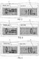
- FIG. 2is a display of the fluid pump of FIG. 1 showing one elevation difference between the fluid pump and a patient;
- FIG. 3is the display of the fluid pump of FIG. 1 showing another elevation difference between the fluid pump and a patient;
- FIG. 4is the display of the fluid pump of FIG. 1 showing yet another elevation difference between the fluid pump and a patient;
- FIG. 5is a block diagram showing one embodiment of a fluid control algorithm of the pump of FIG. 1 ;
- FIG. 6is a graph showing fluid pressure versus time
- FIG. 7is still another graph showing fluid pressure versus time
- FIG. 9is a graph showing fluid pressure at three different fluid flow rates.
- an arthroscopic pumpcan be configured to estimate fluid pressure at a surgical site, e.g., at a joint, to provide an accurate indication of fluid pressure to users (e.g., surgeons and other medical personnel). Fluid pressure at the surgical site may therefore be accurately controlled to improve surgical outcomes.
- the fluid pressure at the surgical sitecan be accurately controlled even when an external flow device is inserted into the joint. Being able to accurately control actual joint pressure to be less than 60 mmHg may help reduce risk to the patient during the surgical procedure, such as by reducing risk of extravasation due to pressure being too high.
- Estimating lossesmay allow for control of surgical site pressure by and adding them to a surgical site pressure set-point, e.g., a joint pressure set-point, to update the pump pressure set-point in a pump pressure control loop, which may be executed quickly.
- the control loopmay therefore provide faster response and more stability than direct control of surgical site pressure.
- FIGS. 1 and 1Aillustrate one embodiment of a pump system including an arthroscopic pump 10 configured to estimate fluid pressure at a surgical site 100 .
- the surgical siteis at a joint such as the knee or shoulder.
- the pump 10is configured to estimate the fluid pressure at the surgical site 100 in real time with performance of the surgical procedure based on at least one of elevation difference between the pump 10 and the surgical site 100 and tubing through which fluid flows between the pump 10 and the surgical site 100 .
- the pump 10is configured to estimate pressure based on each of these two factors, although pressure may be estimated using only one of these factors.
- Each of the inflow tubing 102 and the outflow tubing 104have an associated sheath, in which case the fluid pressure can be estimated based on the tubing 102 and its associated sheath.
- the pump systemalso includes a processor 22 that is configured to control the irrigation pump 10 and the aspiration pump.
- the pump 10is configured to measure fluid pressure at the pump 10 based on fluid pressure within the reservoir 12 and on pump motor speed, e.g., a speed of a motor 24 configured to drive the pump 10 .
- the pump 10is configured to adjust the pressure measured at the pump 10 , as controlled by the processor 22 , to determine estimated pressure at the surgical site 100 using one or more control algorithms, as discussed further below.
- the one or more control algorithmsare stored in a memory 26 of the pump system and are executable by the processor 22 .
- the processor 22 and the memory 26are shown as part of the pump 10 in FIG. 1A , but in other embodiments the processor 22 and/or the memory 26 can be located elsewhere in the pump system.
- the pump systemalso includes a user interface configured to facilitate user interaction with the pump 10 .
- the user interfaceincludes a first display 14 configured to display joint pressure (in mmHg in this illustrated embodiment) in real time with use of the pump 10 during performance of a surgical procedure.
- the fluid pressure shown on the first display 14is the estimated pressure of fluid at the surgical site.
- the user interfacealso includes a second display 16 configured to display shaver speed (in revolutions per minute (RPM) in this illustrated embodiment).
- RPMrevolutions per minute
- the user interfacealso includes user controls configured to receive input from the user to control various pump functions.
- the user controlsinclude depressible +/ ⁇ (up/down) arrow buttons to control adjustment of information on the first display 14 , and depressible +/ ⁇ (up/down) arrow buttons to control adjustment of information on the second display 16 .
- controlsother than buttons may be used for one or both of the displays 14 , 16 , such as knobs, dials, levers, a keypad, or the like.
- Aspiration pump flow ratesare controlled by buttons labelled FLOW+ and SHAVER.
- the FLOW+ flow buttonis configured to be activated with a foot pedal
- the SHAVER flow buttonis configured to be activated when a shaver is enabled.
- the illustrated embodimentalso includes a key that enables filling of the fill chamber 12 and a key that enables SOLO (irrigation pump only) mode.
- a key that enables filling of the fill chamber 12and a key that enables SOLO (irrigation pump only) mode.
- one or both of the FLOW+ and SHAVER buttonscan have another form, such knobs, dials, levers, or the like.
- the illustrated user interfacealso includes lights, e.g., light-emitting diodes (LEDs) or the like, that illuminate to indicate various conditions such as bloodstop, high pressure warning, low pressure alarm, FLOW+ flow rate, SHAVER flow rate, chamber fill enabled, and pump on/off (run/stop).
- LEDslight-emitting diodes
- the pump 10can be configured to estimate pressure by taking into consideration the elevation difference between the pump 10 and the surgical site 100 .
- the user interface in the illustrated embodimentis configured to facilitate the pump's compensation for elevation differences between the pump 10 and the surgical site 100 .
- the second display 16is configured to show the elevation difference between the pump 10 , e.g., the fill level of the fill chamber 12 , and the surgical site 100 at the patient.
- the patient icon 20 on the second display 16is configured to be in one of three positions relative to the pump fill chamber icon 18 to indicate whether the surgical site 100 is elevated above the fill chamber 12 (patient icon 20 in an upper position), the surgical site 100 is at a same elevation as the fill chamber 12 (patient icon 20 in a middle or neutral position), or the surgical site 100 is lower than the fill chamber 12 (patient icon 20 in a lower position).
- the second display 16shows the elevation difference between the fill level of the fill chamber 12 and the surgical site 100 as being ⁇ 5 cm, indicating that the surgical site 100 is 5 cm lower than the pump 10 .
- the patient icon 20is thus in a lower position relative to the pump fill chamber icon 18 on the first display 14 .
- more granular positions of the patient icon 20may be used by having more than three possible positions of the patient icon 20 relative to the pump fill chamber icon 18 .
- the user interfaceis configured to allow a user to adjust the elevation difference using the +/ ⁇ arrows associated with the first display 14 or, alternatively, the +/ ⁇ arrows associated with the second display 16 .
- each push of the + arrowcan increase the elevation difference by a predetermined amount, e.g., 1 cm, 2 cm, 5 cm, 10 cm, etc.
- each push of the ⁇ arrowcan decrease the elevation difference by a predetermined amount, e.g., 1 cm, 2 cm, 5 cm, 10 cm, etc.
- the patient icon 20moves up/down accordingly to provide visual indication of the patient's elevation relative to the pump 10 , and in particular relative to the fluid level in the fill chamber 12 of the pump 10 .
- a positive, non-zero elevation difference indicative of the fill level of the fill chamber 12 being above the surgical site 100can be shown with the patient icon 20 an upper position relative to the pump fill chamber icon 18 on the first display 14 , and in particular relative to the fluid level mark on the pump fill chamber icon 18 .
- FIG. 2shows an elevation difference of +10 cm on the second display 16 and the patient icon 20 thus in the upper position.
- a zero elevation differencecan be shown with the patient icon 20 a middle or neutral position relative to the pump fill chamber icon 18 on the first display 14 , and in particular relative to the fluid level mark on the pump fill chamber icon 18 .
- FIG. 3shows an elevation difference of 0 cm on the second display 16 and the patient icon 20 thus in the middle or neutral position.
- a negative, non-zero elevation difference indicative of the fill level of the fill chamber 12 being below the surgical site 100can be shown with the patient icon 20 a lower position relative to the pump fill chamber icon 18 on the first display 14 , and in particular relative to the fluid level mark on the pump fill chamber icon 18 .
- FIG. 4shows an elevation difference of ⁇ 10 cm on the second display 16 and the patient icon 20 thus in the lower position. Elevation difference may be higher than +10 cm or less than ⁇ 10 cm. For example, elevation difference may be in a range from ⁇ 60 cm to +90 cm.
- the user interfaceis configured to show the elevation icon on the first display 14 upon startup of the pump 10 .
- the useris prompted by instruction on one or both of the displays 14 , 16 and/or by audible instruction through a speaker operatively connected to the pump 10 to confirm relative elevation of the surgical site 100 and pump 10 , in particular the fill level of the pump's chamber 12 .
- the userconfirms the relative elevation by adjusting elevation as needed using the +/ ⁇ arrows associated with the first display 14 .
- the systemmay thus have accurate relative elevation information that the processor 22 can later use in estimating fluid pressure at the surgical site 100 . To accept the displayed elevation as accurate, the user presses the run/stop button.
- the first display 14can continue displaying the elevation icon or can instead display a numerical value of fluid pressure
- the second display 16can continue displaying elevation level or can instead display a numerical value of shaver speed.
- Another press of the run/stop buttonstarts the irrigation pump and the aspiration pump.
- a measurement devicecan be provided that is configured to facilitate the user's input of elevation difference to the pump 10 .
- the pump 10can have a mechanical measurement device mounted thereon, e.g., a ruler or the like, that a user can extend from the pump 10 to the surgical site 100 to allow measurement of surgical site elevation using line of sight.
- the mechanical measurement device mounted to the pump 10can be retractable (similar to a tape measure) to facilitate storage and/or ease of use.
- the pump 10can have a mechanical measurement device mounted thereon as described above in addition to a level laser light source to facilitate measurement of surgical site elevation.
- the level laser light sourcecan be located, for example, at the end of the mechanical measurement device.
- a mechanical measurement devicecan be mounted on a cart on which the pump 10 sits and can be extended from the cart to the surgical site to allow measurement of surgical site elevation using line of sight.
- the mechanical measurement device mounted to the cartcan be retractable (similar to a tape measure) to facilitate storage and/or ease of use.
- the pump 10can have a slide mounted thereon that has a linear encoder (magnetic or optical) mounted thereon. The slide can be selectively movable up and down by a user to align an end of the slide with the surgical site 100 using line of sight, with the linear encoder measuring position.
- the pump 10can have a slide as described above in addition to a level laser light source to facilitate measurement of surgical site elevation.
- the slidecan be selectively movable up and down by a user to align a light beam (e.g., from the light source such as a laser point) with the surgical site 100 , with the linear encoder measuring position.
- a light beame.g., from the light source such as a laser point
- the pump 10can include a laser interferometer configured to measure elevation difference between the pump 10 and the surgical site 100 .
- the pump 10is configured to automatically determine elevation distance between the pump 10 and the surgical site 100 .
- the pump 10is configured to automatically determine elevation on startup of the pump 10 so the pump 10 has the relevant information needed to adjust fluid pressure in view of the elevation difference when the pump 10 is in use.
- the pump 10can be configured to zero the pressure at the level of the surgical site 100 to allow for compensation of any elevation difference between the surgical site 100 and the pump 10 .
- the userwill press the run/stop button on the pump's user interface. An icon will then show on the first display 14 and/or the second display 16 indicating that a pressure calibration will occur.
- the userwill hold the sheath connected to the end of the irrigation tubing 102 that runs between the pump 10 and the surgical site 100 at the level of the surgical site 100 , e.g., at joint level, with the pump's irrigation valve open and then press the run/stop button for the second time.
- the pump 10can be configured to prompt the user to hold the sheath at the level of the surgical site 100 , such as by instruction on one or both of the displays 14 , 16 and/or by audible instruction through a speaker operatively connected to the pump 10 .
- the pump's irrigation pumpwill then function in flow control mode for sufficient time for it to prime. At this time, the pressure will be recorded for a predetermined amount of time, e.g., a few tenths of a second, and averaged. Then the irrigation flow will be increased to provide another pressure data point.
- These two pressure versus flow data pointswill be used by the pump 10 , e.g., a processor 22 thereof, in a control algorithm to estimate the elevation of the surgical site 100 relative to the pump 10 as well at the losses in the tubing and sheath.
- the results of the algorithmwill then be limit checked by the pump 10 , e.g., by the processor 22 thereof, and if the results are within a predetermined tolerance, the pump 10 will end the autocalibration.
- the end of autocalibrationmay be indicated by the pump 10 , such as with audible sound such as a beep and/or with a visual on one or both of the displays 14 , 16 .
- depressing the run/stop buttonwill allow the user to adjust the joint pressure set-point and shaver RPM speed set-point.
- Another press of the run/stop buttonwill start the pump 10 in its normal pressure regulation mode.
- the pump 10can be configured to estimate pressure by taking into consideration the tubing 102 , 104 and, if present, the sheaths associated with the tubing 102 , 104 .
- the pump 10can be configured to allow a user to input tubing size and/or sheath size.
- the pump 10can be configured to use the input size in evaluating pressure loss compensation due to the tubing and sheath that runs between the pump 10 and the surgical site 100 .
- the pump's user interfacecan include a depressible sheath size control button that allows the user to use the +/ ⁇ arrows associated with the first display 14 or the second display 16 to adjust sheath size up/down to reflect the current sheath size. Depressing the sheath size control button again can indicate acceptance of the displayed sheath size.
- a depressible sheath size control buttonthat allows the user to use the +/ ⁇ arrows associated with the first display 14 or the second display 16 to adjust sheath size up/down to reflect the current sheath size. Depressing the sheath size control button again can indicate acceptance of the displayed sheath size.
- a control other than a buttonmay be used for inputting sheath size, such as knobs, dials, levers, a keypad, or the like.
- the pump's user interfacecan include a depressible tubing size control button that allows the user to use the +/ ⁇ arrows associated with the first display 14 or the second display 16 to adjust tubing size up/down to reflect the current tubing size similar to that discussed above regarding the input of sheath size.
- a control other than a buttonmay be used for inputting tubing size, such as knobs, dials, levers, a keypad, or the like.
- control algorithmthat the pump system can use to estimate and control fluid pressure based on at least tubing loss and sheath loss is described below with respect to FIG. 5 .
- the control algorithmis implemented in a combination of software and hardware.
- the processor 22is configured to execute the control algorithm using various electronic components, as will be appreciated by a person skilled in the art, such as pump components of a rotary encoder, motor/gearbox, pressure transducer, and interface/control circuits.
- the algorithmfirst determines a pump pressure set-point by estimating tubing/sheath losses and adding this pressure drop to the joint pressure set-point.
- a pump pressure control loopis then controlled using a proportional plus integral (PI) controller. Additionally, feedforward control from the suction pump is applied to anticipate sudden flow changes induced by the aspiration pump, such as flow+ and shaver flows.
- the pressure control signal(from the PI controller) combined with the feedforward signal from the suction pump provide a velocity command to an irrigation velocity control loop.
- FIG. 5illustrates the irrigation pump control loop.
- the pump pressure set-pointis updated based on the estimated losses in the tubing and sheath.
- the estimation algorithmis updated on a regular basis as opposed to only when changing flow mode.
- the regular basiscan be any of a variety of predetermined intervals during use of the pump system, such as every X seconds, every Y minutes, etc.
- the irrigation pumpis configured to control the pressure at the surgical site, e.g., in the surgical joint where arthroscopic surgery is being performed. However, pressure is not measured at the joint but only at the pump, e.g., in the fill chamber. So, to regulate joint pressure, tubing/sheath losses are estimated and then added to the desired joint pressure P joint _ cmd , e.g., the pressure set-point previously input to the pump and/or as preset at the pump, to provide the updated pump pressure set-point P pump _ cmd .
- the basis for adding desired joint pressure to tubing/sheath loss to produce the updated pump pressure set-pointis that the pump pressure is equal to the joint pressure plus the tubing/sheath pressure drop.
- the tubing/sheath lossesare a function of flow and are therefore a function of a speed of the pump system's irrigation motor.
- the algorithmtherefore takes motor speed w into account to estimate fluid pressure at the surgical site, e.g., at the joint.
- the velocity commandis updated on a regular basis as the output of the pressure loop PI (Proportional, Integral) controller used for pressure regulation.
- the regular basiscan be any of a variety of predetermined intervals during use of the pump system, such as every X seconds, every Y minutes, etc.
- the pressure control systemuses the same velocity control strategy as for the suction pump, so the pressure controller (PI) provides a velocity command to the velocity control loop and this update is used in the controller calculations.
- the pressure loop PI controlleris updated in the 2 KHz timer interrupt which is also used for control of the suction pump and the shaver.
- the above equationis executed on a regular predetermine basis, e.g., every 32 msec, however, the TubeSheathLoss is only updated when the pump pressure has settled: If successive readings (spaced at, e.g., 500 msec) are within, e.g., 2 mmHg of each other.
- a control loopis used for regulating the angular velocity of the suction (aspiration) pump. While both current and velocity feedback can be used, current feedback is not required.
- the controller outputprovides a PWM duty cycle to the motor using a 20 KHz PWM output compare timer. Additionally, a rate limit is provided to the PWM outputs so that pulses are ramped at each transition to eliminate the pulsing of the motor at 2 KHz which would certainly be audible.
- the rate limitis 10 encoderCnts/2 KHz interrupt. This means that the motor can go from zero to max speed within 0.8 seconds.
- a motor velocity feedforward termis provided from the suction motor speed command. This helps the joint pressure control loop to anticipate local (i.e., caused by this pump) flow disturbances such as enabling or disabling the shaver or flow+.
- Suction speed feedforwardis multiplied by the pump efficiency ratio to provide the correct steady state feedforward flow compensation in the irrigation pump to offset the additional flow in the suction pump.
- a rampis applied to the suction feedforward speed to try to offset the speed ramp in the suction pump used for shaver and Flow+ flows.
- Feedforward suction speed compensationis combined with the output of the PID controller to provide a velocity command to the velocity control loop used for the irrigation pump. This velocity control loop is identical to the suction pump.
- the pressure displayedis the estimated joint pressure updated every half second and additional filtering.
- the factory default joint pressure settingis 70 mmHg, although the default can be updated by the user with the default menu. In other implementations, the factory default pressure setting is 50 mmHg.
- Suction pump operationonly requires the user to press the RUN button, as long as SOLO mode is not selected and a door of the pump system is closed. This is assuming that no faults exist such an over-current for the pump motors.
- the irrigation (inflow) pump controluses a 2 KHz timer and two separate control mechanisms pressure (two pressure sensors) and velocity (high speed encoder) to control the motor speed.
- FIG. 5shows the overall control loop for regulating the pressure.
- the 2 KHz loopalong with the state-chart processing below performs the following: (1) The pressure controller uses the readings from two analog channels (ADC) to determine the difference between the pressure set-point and the actual pressure read at the pressure sensors. These signals are read and averaged together. Based on this difference (error) the new command PWM duty cycle counts value that is fed into the velocity portion of the motor control loop is determined; and (2) the velocity controller uses the feedback from the high-speed encoder (frequency) which is tied to an Input Capture Compare Timer. Using the command counts determined in the previous step and the speed frequency of the motor a new duty cycle to the PWM command input is calculated. This command is then fed into the PWM control register associated with the Inflow motor. The PWM frequency is, e.g., 20 Khz. The two pressure signals are monitored and compared to ensure that they are accurate within a predetermined threshold, e.g., +/ ⁇ 10%, from each other.
- ADCanalog channels
- FIGS. 6-8are graphs showing various scenarios in which fluid pressure at the pump, e.g., pressure measured at the fill level of the pump's fill chamber, differs from fluid pressure at the surgical site. These illustrated differences between pressure at the pump and pressure at the surgical site help highlight the importance of estimating pressure at the surgical site instead of considering pressure measured at the pump to be an accurate reflection of pressure at the surgical site.
- FIG. 6is a graph showing pressure (in mmHg) versus time (in tenths of a second) in response to a 30 mmHg step (70 mmHg to 100 mmHg) for pressure at the fluid pump and estimated pressure at the surgical site (which is a joint in this embodiment) calculated by the fluid pump with compensation for elevation and tubing/sheath losses.
- the graphshows that the pressure at the fluid pump differs only slightly from the estimated pressure at the surgical site.
- FIG. 7is a graph showing pressure (in mmHg) versus time (in tenths of a second) in response to a step change in flow of about 350 mL/min due to an internal shaver suction source active from about 5 sec to about 250 sec.
- the graphshows that the pressure at the fluid pump increases as flow increases in order to regulate joint pressure while the shaver is enabled.
- FIG. 8is a graph showing pressure (in mmHg) versus time (in tenths of a second) in response to a step change in flow of about 350 mL/min due to an external suction source active from about 5 sec to about 25 sec. The graph shows that the pressure at the fluid pump increases to regulate the pressure at the surgical site.
- FIG. 9is a graph demonstrating the effectiveness of controlling fluid pressure at the surgical site using the fluid pressure estimation that is described herein.
- the graph of FIG. 9shows pressure (in mmHg) at three different fluid flow rates: idle flow, medium flow, and high flow.
- the graphshows that by estimating fluid pressure at the surgical site as described herein, the fluid pressure at the surgical site can be accurately controlled to allow surgeons to use a lower pressure set-point, which may help improve patient safety, e.g., help reduce the risk of extravasation or otherwise help improve patient safety, by maintaining fluid pressure at a safe level.
- the pressure set-point in this exampleis 50 mmHg, and the site pressure in this example is 47 mmHg at idle flow, 49 mmHg at medium flow, and 43 mmHg at high flow, which is very good pressure regulation over such a flow range.
Landscapes
- Health & Medical Sciences (AREA)
- Heart & Thoracic Surgery (AREA)
- Life Sciences & Earth Sciences (AREA)
- Public Health (AREA)
- Engineering & Computer Science (AREA)
- Veterinary Medicine (AREA)
- Biomedical Technology (AREA)
- Animal Behavior & Ethology (AREA)
- General Health & Medical Sciences (AREA)
- Hematology (AREA)
- Anesthesiology (AREA)
- Vascular Medicine (AREA)
- Surgery (AREA)
- Pulmonology (AREA)
- Nuclear Medicine, Radiotherapy & Molecular Imaging (AREA)
- Medical Informatics (AREA)
- Molecular Biology (AREA)
- External Artificial Organs (AREA)
- Infusion, Injection, And Reservoir Apparatuses (AREA)
- Surgical Instruments (AREA)
Abstract
Description
Tube/Sheath Loss [mmHg]=4.70*ω2+0.0091*ω+10
Velocity=1406250 [clkPulses/sec]/time between Encoder pulses
setPointPumpPress=setPointJointPress+TubeSheathLoss
Pcontrol=error*K+SUM_ERROR*Ki−Kd*dErr
VELCMD=Pcontrol+suctionFeedForward
Claims (20)
Priority Applications (8)
| Application Number | Priority Date | Filing Date | Title |
|---|---|---|---|
| US16/114,510US10874776B2 (en) | 2017-09-01 | 2018-08-28 | Methods, systems, and devices for joint to pump elevation level user interfaces, autocalibration for joint elevation, and joint pressure estimation |
| EP18850625.7AEP3668565B1 (en) | 2017-09-01 | 2018-08-30 | Joint to pump elevation level user interfaces, autocalibration for joint elevation, and joint pressure estimation |
| CN201880056537.6ACN112955195A (en) | 2017-09-01 | 2018-08-30 | Joint to pump height level user interface, joint height auto calibration, and joint pressure estimation |
| JP2020512400AJP7234215B2 (en) | 2017-09-01 | 2018-08-30 | Pump-to-joint altitude level user interface, automatic joint altitude calibration, and joint pressure estimation |
| BR112020003881-4ABR112020003881A2 (en) | 2017-09-01 | 2018-08-30 | user interfaces for level of articulation and pump elevation, self-calibration for articulation elevation, and joint pressure estimation |
| PCT/US2018/048814WO2019046560A1 (en) | 2017-09-01 | 2018-08-30 | Joint to pump elevation level user interfaces, autocalibration for joint elevation, and joint pressure estimation |
| AU2018324074AAU2018324074B2 (en) | 2017-09-01 | 2018-08-30 | Joint to pump elevation level user interfaces, autocalibration for joint elevation, and joint pressure estimation |
| US17/109,399US11878103B2 (en) | 2017-09-01 | 2020-12-02 | Methods, systems, and devices for joint to pump elevation level user interfaces, autocalibration for joint elevation, and joint pressure estimation |
Applications Claiming Priority (2)
| Application Number | Priority Date | Filing Date | Title |
|---|---|---|---|
| US201762553397P | 2017-09-01 | 2017-09-01 | |
| US16/114,510US10874776B2 (en) | 2017-09-01 | 2018-08-28 | Methods, systems, and devices for joint to pump elevation level user interfaces, autocalibration for joint elevation, and joint pressure estimation |
Related Child Applications (1)
| Application Number | Title | Priority Date | Filing Date |
|---|---|---|---|
| US17/109,399ContinuationUS11878103B2 (en) | 2017-09-01 | 2020-12-02 | Methods, systems, and devices for joint to pump elevation level user interfaces, autocalibration for joint elevation, and joint pressure estimation |
Publications (2)
| Publication Number | Publication Date |
|---|---|
| US20190070343A1 US20190070343A1 (en) | 2019-03-07 |
| US10874776B2true US10874776B2 (en) | 2020-12-29 |
Family
ID=65517078
Family Applications (2)
| Application Number | Title | Priority Date | Filing Date |
|---|---|---|---|
| US16/114,510Active2039-01-30US10874776B2 (en) | 2017-09-01 | 2018-08-28 | Methods, systems, and devices for joint to pump elevation level user interfaces, autocalibration for joint elevation, and joint pressure estimation |
| US17/109,399Active2039-07-18US11878103B2 (en) | 2017-09-01 | 2020-12-02 | Methods, systems, and devices for joint to pump elevation level user interfaces, autocalibration for joint elevation, and joint pressure estimation |
Family Applications After (1)
| Application Number | Title | Priority Date | Filing Date |
|---|---|---|---|
| US17/109,399Active2039-07-18US11878103B2 (en) | 2017-09-01 | 2020-12-02 | Methods, systems, and devices for joint to pump elevation level user interfaces, autocalibration for joint elevation, and joint pressure estimation |
Country Status (7)
| Country | Link |
|---|---|
| US (2) | US10874776B2 (en) |
| EP (1) | EP3668565B1 (en) |
| JP (1) | JP7234215B2 (en) |
| CN (1) | CN112955195A (en) |
| AU (1) | AU2018324074B2 (en) |
| BR (1) | BR112020003881A2 (en) |
| WO (1) | WO2019046560A1 (en) |
Cited By (4)
| Publication number | Priority date | Publication date | Assignee | Title |
|---|---|---|---|---|
| WO2023281092A1 (en) | 2021-07-08 | 2023-01-12 | Medos International Sarl | Arthroscopic Pump Saline Management |
| US11878103B2 (en) | 2017-09-01 | 2024-01-23 | Medos International Sarl | Methods, systems, and devices for joint to pump elevation level user interfaces, autocalibration for joint elevation, and joint pressure estimation |
| USD1016854S1 (en)* | 2021-12-28 | 2024-03-05 | Stryker Corporation | Display screen or portion thereof with a bed bay identification icon |
| WO2024149771A1 (en) | 2023-01-10 | 2024-07-18 | Medos International Sarl | Anthroscopic pump saline management |
Families Citing this family (5)
| Publication number | Priority date | Publication date | Assignee | Title |
|---|---|---|---|---|
| USD893547S1 (en)* | 2018-08-28 | 2020-08-18 | DePuy Synthes Products, Inc. | Surgical pump display screen or portion thereof with graphical user interface |
| USD896266S1 (en)* | 2018-11-05 | 2020-09-15 | Stryker Corporation | Display screen or portion thereof with graphical user interface |
| USD924922S1 (en)* | 2019-07-12 | 2021-07-13 | GE Precision Healthcare LLC | Display screen with graphical user interface |
| US20230010088A1 (en)* | 2021-07-08 | 2023-01-12 | Medos International Sarl | Arthroscopic Pump Saline Management |
| US20230255822A1 (en)* | 2022-02-14 | 2023-08-17 | Johnson & Johnson Surgical Vision, Inc. | Controlling constant intraocular pressure using adaptive flow rates of irrigation and aspiration fluids |
Citations (62)
| Publication number | Priority date | Publication date | Assignee | Title |
|---|---|---|---|---|
| USD276819S (en) | 1981-08-07 | 1984-12-18 | Mattel, Inc. | Video graphic figure font or the like |
| USD278804S (en) | 1981-07-23 | 1985-05-14 | Kabushiki Kaisha Suwa Seikosha | Design for display panel for electronic timepiece |
| USD281081S (en) | 1981-09-15 | 1985-10-22 | Ruedi Zwissler | Font of symbols |
| US5315530A (en) | 1990-09-10 | 1994-05-24 | Rockwell International Corporation | Real-time control of complex fluid systems using generic fluid transfer model |
| US5520638A (en) | 1995-03-28 | 1996-05-28 | Arthrex, Inc. | Main pump tubing for arthroscopy infusion pump |
| US5630799A (en)* | 1991-08-21 | 1997-05-20 | Smith & Nephew Dyonics Inc. | Fluid management system |
| US5830180A (en) | 1996-07-17 | 1998-11-03 | Aquarius Medical Corporation | Fluid management system for arthroscopic surgery |
| US6024720A (en) | 1995-07-18 | 2000-02-15 | Aquarius Medical Corporation | Fluid management system for arthroscopic surgery |
| US6176847B1 (en) | 1999-05-14 | 2001-01-23 | Circon Corporation | Surgical irrigation system incorporating flow sensor device |
| US6394974B1 (en) | 1997-01-22 | 2002-05-28 | Allergan Sales, Inc. | Power mode phaco |
| US20030052787A1 (en) | 2001-08-03 | 2003-03-20 | Zerhusen Robert Mark | Patient point-of-care computer system |
| US20050092523A1 (en) | 2003-10-30 | 2005-05-05 | Power Chokes, L.P. | Well pressure control system |
| US7010369B2 (en) | 1997-11-07 | 2006-03-07 | Hill-Rom Services, Inc. | Medical equipment controller |
| US20060290515A1 (en) | 2005-06-23 | 2006-12-28 | Jukka Kankkunen | Fastening means for a patient monitor |
| US20070078370A1 (en)* | 2005-06-13 | 2007-04-05 | Smith & Nephew, Inc. *Ew* | Surgical Fluid Management |
| USD572725S1 (en) | 2007-08-13 | 2008-07-08 | Alert Life Sciences Computing, S.A. | Icon for a portion of a display screen |
| USD572724S1 (en) | 2007-08-13 | 2008-07-08 | Alert Life Sciences Computing, S.A. | Icon for a portion of a display screen |
| US7421316B2 (en) | 2000-07-10 | 2008-09-02 | Deka Products Limited Partnership | Method and device for regulating fluid pump pressures |
| US7510542B2 (en) | 2006-12-20 | 2009-03-31 | Linvatec Corporation | Dual pump irrigation/aspiration system and method for determining joint pressure |
| US7628054B2 (en) | 2006-11-09 | 2009-12-08 | Abbott Medical Optics Inc. | Calibration utility for non-linear measurement system |
| US20100010584A1 (en) | 2008-07-11 | 2010-01-14 | Medtronic, Inc. | Posture state display on medical device user interface |
| US20100050085A1 (en) | 2006-09-29 | 2010-02-25 | Draeger Medical Systems, Inc. | System for processing, deriving and displaying relationships among patient medical parameters |
| USD611498S1 (en) | 2009-01-26 | 2010-03-09 | A-Dec, Inc. | Controller for a bed or chair with symbol set |
| US20100069937A1 (en) | 2008-09-16 | 2010-03-18 | Seiko Epson Corporation | Fluid jet device, drive device of fluid jet device, surgical instrument, and method of driving fluid jet device |
| US20120089419A1 (en) | 2010-10-08 | 2012-04-12 | Huster Keith A | Hospital bed with graphical user interface having advanced functionality |
| US20120130308A1 (en) | 2005-04-11 | 2012-05-24 | Hospira, Inc. | User interface improvements for medical devices |
| US20120138533A1 (en) | 2010-12-01 | 2012-06-07 | Curtis James R | Dialysis system control system with user interface |
| US20120302941A1 (en) | 2011-05-23 | 2012-11-29 | Dan Teodorescu | Phacoemulsification systems and associated user-interfaces and methods |
| US8424362B2 (en) | 2006-11-09 | 2013-04-23 | Abbott Medical Optics Inc. | Methods and apparatus for calibrating a vacuum component of a phacoemulsification system |
| US20130317417A1 (en) | 2012-05-25 | 2013-11-28 | Abbott Medical Optics Inc. | Surgical handpiece having directional fluid control capabilities |
| US20140026322A1 (en) | 2012-07-24 | 2014-01-30 | Randall J. Bell | Proxy caregiver interface |
| US20140171959A1 (en) | 2012-12-17 | 2014-06-19 | Alcon Research, Ltd. | Wearable User Interface for Use with Ocular Surgical Console |
| US20140278524A1 (en) | 2013-03-12 | 2014-09-18 | Cerner Innovation, Inc. | Associating patients and medical devices with a mobile device via bluetooth |
| US20150025450A1 (en) | 2006-11-09 | 2015-01-22 | Abbott Medical Optics Inc. | Reversible Peristaltic Pump and Other Structures for Reflux in Eye Surgery |
| US20150057774A1 (en) | 2013-08-22 | 2015-02-26 | Novartis Ag | Graphical user interface for surgical console |
| US20150133895A1 (en) | 2012-06-12 | 2015-05-14 | Eos Gmbh | Device for adjusting the irrigation pressure in eye operations |
| US9089367B2 (en) | 2010-04-08 | 2015-07-28 | Alcon Research, Ltd. | Patient eye level touch control |
| USD738928S1 (en) | 2013-12-02 | 2015-09-15 | Medtronic, Inc. | Display screen with icon |
| USD738929S1 (en) | 2013-12-02 | 2015-09-15 | Medtronic, Inc. | Display screen with icon |
| US20150277703A1 (en) | 2014-02-25 | 2015-10-01 | Stephen Rhett Davis | Apparatus for digital signage alerts |
| US20150290387A1 (en) | 2013-11-08 | 2015-10-15 | Bonvisi Ab | Device for irrigation and insufflation with blood pressure dependent pressure control |
| US9162023B2 (en) | 2011-05-05 | 2015-10-20 | Carefusion 303, Inc. | Automated pressure limit setting method and apparatus |
| USD742917S1 (en) | 2013-10-11 | 2015-11-10 | Microsoft Corporation | Display screen with transitional graphical user interface |
| US9205186B2 (en) | 2013-03-14 | 2015-12-08 | Abbott Medical Optics Inc. | System and method for providing pressurized infusion |
| US9211096B2 (en) | 2009-10-08 | 2015-12-15 | The Regents Of The University Of Michigan | Real time clinical decision support system having medical systems as display elements |
| US9289541B2 (en) | 2008-08-22 | 2016-03-22 | Medtronic, Inc. | Surgical fluid management system |
| US9289110B2 (en) | 2012-04-05 | 2016-03-22 | Stryker Corporation | Control for surgical fluid management pump system |
| US9295582B2 (en) | 2013-03-13 | 2016-03-29 | Abbott Medical Optics Inc. | Fluidics adjustment techniques for use in a surgical procedure |
| USD759063S1 (en) | 2013-02-14 | 2016-06-14 | Healthmate International, LLC | Display screen with graphical user interface for an electrotherapy device |
| US9433723B2 (en) | 2013-03-14 | 2016-09-06 | Abbott Medical Optics Inc. | System and method for providing pressurized infusion |
| USD772905S1 (en) | 2014-11-14 | 2016-11-29 | Volvo Car Corporation | Display screen with graphical user interface |
| US20160346443A1 (en) | 2015-05-26 | 2016-12-01 | Brady L. WOOLFORD | Pressure control algorithm for high resistance hardware |
| US20160346454A1 (en) | 2015-05-26 | 2016-12-01 | Brady L. WOOLFORD | Pump and means for controlling a pump |
| US9597445B2 (en) | 2011-11-11 | 2017-03-21 | Abbott Medical Optics Inc. | Fluid management system for use in a medical procedure |
| US20170157312A1 (en) | 2012-04-05 | 2017-06-08 | Brady Woolford | Cassette for a surgical fluid management pump system |
| US20170209639A1 (en) | 2014-07-23 | 2017-07-27 | Olympus Winter & Ibe Gmbh | Pump device |
| USD800162S1 (en) | 2016-03-22 | 2017-10-17 | Teletracking Technologies, Inc. | Display screen with graphical user interface icon |
| US9830424B2 (en) | 2013-09-18 | 2017-11-28 | Hill-Rom Services, Inc. | Bed/room/patient association systems and methods |
| US20180184984A1 (en) | 2017-01-04 | 2018-07-05 | Hill-Rom Services, Inc. | Patient support apparatus having vital signs monitoring and alerting |
| USD835151S1 (en) | 2014-09-19 | 2018-12-04 | Rapidsos, Inc. | Computer display panel with an emergency communications initiation interface |
| USD877755S1 (en) | 2018-03-12 | 2020-03-10 | Minebea Mitsumi Inc. | Display screen with graphical user interface |
| USD881237S1 (en) | 2018-09-14 | 2020-04-14 | Fujitsu Limited | Display screen with icons |
Family Cites Families (3)
| Publication number | Priority date | Publication date | Assignee | Title |
|---|---|---|---|---|
| US7981073B2 (en)* | 2006-03-30 | 2011-07-19 | Moellstam Anders | Method and device for irrigation of body cavities |
| US10874776B2 (en) | 2017-09-01 | 2020-12-29 | Medos International Sarl | Methods, systems, and devices for joint to pump elevation level user interfaces, autocalibration for joint elevation, and joint pressure estimation |
| USD893547S1 (en) | 2018-08-28 | 2020-08-18 | DePuy Synthes Products, Inc. | Surgical pump display screen or portion thereof with graphical user interface |
- 2018
- 2018-08-28USUS16/114,510patent/US10874776B2/enactiveActive
- 2018-08-30EPEP18850625.7Apatent/EP3668565B1/enactiveActive
- 2018-08-30JPJP2020512400Apatent/JP7234215B2/enactiveActive
- 2018-08-30WOPCT/US2018/048814patent/WO2019046560A1/ennot_activeCeased
- 2018-08-30BRBR112020003881-4Apatent/BR112020003881A2/ennot_activeIP Right Cessation
- 2018-08-30AUAU2018324074Apatent/AU2018324074B2/enactiveActive
- 2018-08-30CNCN201880056537.6Apatent/CN112955195A/enactivePending
- 2020
- 2020-12-02USUS17/109,399patent/US11878103B2/enactiveActive
Patent Citations (64)
| Publication number | Priority date | Publication date | Assignee | Title |
|---|---|---|---|---|
| USD278804S (en) | 1981-07-23 | 1985-05-14 | Kabushiki Kaisha Suwa Seikosha | Design for display panel for electronic timepiece |
| USD276819S (en) | 1981-08-07 | 1984-12-18 | Mattel, Inc. | Video graphic figure font or the like |
| USD281081S (en) | 1981-09-15 | 1985-10-22 | Ruedi Zwissler | Font of symbols |
| US5315530A (en) | 1990-09-10 | 1994-05-24 | Rockwell International Corporation | Real-time control of complex fluid systems using generic fluid transfer model |
| US5630799A (en)* | 1991-08-21 | 1997-05-20 | Smith & Nephew Dyonics Inc. | Fluid management system |
| US5520638A (en) | 1995-03-28 | 1996-05-28 | Arthrex, Inc. | Main pump tubing for arthroscopy infusion pump |
| US6024720A (en) | 1995-07-18 | 2000-02-15 | Aquarius Medical Corporation | Fluid management system for arthroscopic surgery |
| US5830180A (en) | 1996-07-17 | 1998-11-03 | Aquarius Medical Corporation | Fluid management system for arthroscopic surgery |
| US6394974B1 (en) | 1997-01-22 | 2002-05-28 | Allergan Sales, Inc. | Power mode phaco |
| US7010369B2 (en) | 1997-11-07 | 2006-03-07 | Hill-Rom Services, Inc. | Medical equipment controller |
| US6176847B1 (en) | 1999-05-14 | 2001-01-23 | Circon Corporation | Surgical irrigation system incorporating flow sensor device |
| US7421316B2 (en) | 2000-07-10 | 2008-09-02 | Deka Products Limited Partnership | Method and device for regulating fluid pump pressures |
| US20030052787A1 (en) | 2001-08-03 | 2003-03-20 | Zerhusen Robert Mark | Patient point-of-care computer system |
| US20050092523A1 (en) | 2003-10-30 | 2005-05-05 | Power Chokes, L.P. | Well pressure control system |
| US20120130308A1 (en) | 2005-04-11 | 2012-05-24 | Hospira, Inc. | User interface improvements for medical devices |
| US20070078370A1 (en)* | 2005-06-13 | 2007-04-05 | Smith & Nephew, Inc. *Ew* | Surgical Fluid Management |
| US7604610B2 (en) | 2005-06-13 | 2009-10-20 | Smith & Nephew, Inc. | Surgical fluid management |
| US20060290515A1 (en) | 2005-06-23 | 2006-12-28 | Jukka Kankkunen | Fastening means for a patient monitor |
| US20100050085A1 (en) | 2006-09-29 | 2010-02-25 | Draeger Medical Systems, Inc. | System for processing, deriving and displaying relationships among patient medical parameters |
| US20150025450A1 (en) | 2006-11-09 | 2015-01-22 | Abbott Medical Optics Inc. | Reversible Peristaltic Pump and Other Structures for Reflux in Eye Surgery |
| US8424362B2 (en) | 2006-11-09 | 2013-04-23 | Abbott Medical Optics Inc. | Methods and apparatus for calibrating a vacuum component of a phacoemulsification system |
| US7628054B2 (en) | 2006-11-09 | 2009-12-08 | Abbott Medical Optics Inc. | Calibration utility for non-linear measurement system |
| US7510542B2 (en) | 2006-12-20 | 2009-03-31 | Linvatec Corporation | Dual pump irrigation/aspiration system and method for determining joint pressure |
| USD572725S1 (en) | 2007-08-13 | 2008-07-08 | Alert Life Sciences Computing, S.A. | Icon for a portion of a display screen |
| USD572724S1 (en) | 2007-08-13 | 2008-07-08 | Alert Life Sciences Computing, S.A. | Icon for a portion of a display screen |
| US20100010584A1 (en) | 2008-07-11 | 2010-01-14 | Medtronic, Inc. | Posture state display on medical device user interface |
| US9289541B2 (en) | 2008-08-22 | 2016-03-22 | Medtronic, Inc. | Surgical fluid management system |
| US20100069937A1 (en) | 2008-09-16 | 2010-03-18 | Seiko Epson Corporation | Fluid jet device, drive device of fluid jet device, surgical instrument, and method of driving fluid jet device |
| USD611498S1 (en) | 2009-01-26 | 2010-03-09 | A-Dec, Inc. | Controller for a bed or chair with symbol set |
| US9211096B2 (en) | 2009-10-08 | 2015-12-15 | The Regents Of The University Of Michigan | Real time clinical decision support system having medical systems as display elements |
| US9089367B2 (en) | 2010-04-08 | 2015-07-28 | Alcon Research, Ltd. | Patient eye level touch control |
| US20120089419A1 (en) | 2010-10-08 | 2012-04-12 | Huster Keith A | Hospital bed with graphical user interface having advanced functionality |
| US20120138533A1 (en) | 2010-12-01 | 2012-06-07 | Curtis James R | Dialysis system control system with user interface |
| US20160030668A1 (en) | 2011-05-05 | 2016-02-04 | Carefusion 303, Inc. | Automated pressure limit setting method and apparatus |
| US9162023B2 (en) | 2011-05-05 | 2015-10-20 | Carefusion 303, Inc. | Automated pressure limit setting method and apparatus |
| US20120302941A1 (en) | 2011-05-23 | 2012-11-29 | Dan Teodorescu | Phacoemulsification systems and associated user-interfaces and methods |
| US9597445B2 (en) | 2011-11-11 | 2017-03-21 | Abbott Medical Optics Inc. | Fluid management system for use in a medical procedure |
| US9289110B2 (en) | 2012-04-05 | 2016-03-22 | Stryker Corporation | Control for surgical fluid management pump system |
| US20170157312A1 (en) | 2012-04-05 | 2017-06-08 | Brady Woolford | Cassette for a surgical fluid management pump system |
| US20130317417A1 (en) | 2012-05-25 | 2013-11-28 | Abbott Medical Optics Inc. | Surgical handpiece having directional fluid control capabilities |
| US20150133895A1 (en) | 2012-06-12 | 2015-05-14 | Eos Gmbh | Device for adjusting the irrigation pressure in eye operations |
| US20140026322A1 (en) | 2012-07-24 | 2014-01-30 | Randall J. Bell | Proxy caregiver interface |
| US20140171959A1 (en) | 2012-12-17 | 2014-06-19 | Alcon Research, Ltd. | Wearable User Interface for Use with Ocular Surgical Console |
| USD759063S1 (en) | 2013-02-14 | 2016-06-14 | Healthmate International, LLC | Display screen with graphical user interface for an electrotherapy device |
| US20140278524A1 (en) | 2013-03-12 | 2014-09-18 | Cerner Innovation, Inc. | Associating patients and medical devices with a mobile device via bluetooth |
| US9295582B2 (en) | 2013-03-13 | 2016-03-29 | Abbott Medical Optics Inc. | Fluidics adjustment techniques for use in a surgical procedure |
| US9205186B2 (en) | 2013-03-14 | 2015-12-08 | Abbott Medical Optics Inc. | System and method for providing pressurized infusion |
| US9433723B2 (en) | 2013-03-14 | 2016-09-06 | Abbott Medical Optics Inc. | System and method for providing pressurized infusion |
| US20150057774A1 (en) | 2013-08-22 | 2015-02-26 | Novartis Ag | Graphical user interface for surgical console |
| US9830424B2 (en) | 2013-09-18 | 2017-11-28 | Hill-Rom Services, Inc. | Bed/room/patient association systems and methods |
| USD742917S1 (en) | 2013-10-11 | 2015-11-10 | Microsoft Corporation | Display screen with transitional graphical user interface |
| US20150290387A1 (en) | 2013-11-08 | 2015-10-15 | Bonvisi Ab | Device for irrigation and insufflation with blood pressure dependent pressure control |
| USD738929S1 (en) | 2013-12-02 | 2015-09-15 | Medtronic, Inc. | Display screen with icon |
| USD738928S1 (en) | 2013-12-02 | 2015-09-15 | Medtronic, Inc. | Display screen with icon |
| US20150277703A1 (en) | 2014-02-25 | 2015-10-01 | Stephen Rhett Davis | Apparatus for digital signage alerts |
| US20170209639A1 (en) | 2014-07-23 | 2017-07-27 | Olympus Winter & Ibe Gmbh | Pump device |
| USD835151S1 (en) | 2014-09-19 | 2018-12-04 | Rapidsos, Inc. | Computer display panel with an emergency communications initiation interface |
| USD772905S1 (en) | 2014-11-14 | 2016-11-29 | Volvo Car Corporation | Display screen with graphical user interface |
| US20160346443A1 (en) | 2015-05-26 | 2016-12-01 | Brady L. WOOLFORD | Pressure control algorithm for high resistance hardware |
| US20160346454A1 (en) | 2015-05-26 | 2016-12-01 | Brady L. WOOLFORD | Pump and means for controlling a pump |
| USD800162S1 (en) | 2016-03-22 | 2017-10-17 | Teletracking Technologies, Inc. | Display screen with graphical user interface icon |
| US20180184984A1 (en) | 2017-01-04 | 2018-07-05 | Hill-Rom Services, Inc. | Patient support apparatus having vital signs monitoring and alerting |
| USD877755S1 (en) | 2018-03-12 | 2020-03-10 | Minebea Mitsumi Inc. | Display screen with graphical user interface |
| USD881237S1 (en) | 2018-09-14 | 2020-04-14 | Fujitsu Limited | Display screen with icons |
Non-Patent Citations (15)
| Title |
|---|
| "Bed, hopsital, medical, patient, sick, treatment icon" Feb. 11, 2017, posted at iconfinder.com [site visited Apr. 14, 2020]. https://www.iconfinder.com/iconsets/medical-health-care-blue-series-set-1. |
| "Fluid Management System" Nov. 28, 2018, posted at a1medtech.com [site visited Dec. 2, 2019]. https://www.a1medtech.com/Fluid-Management-System_c_115.html. |
| "Hospital Bed Remote Control Panel stock photo" Jun. 11, 2012, posted at istockphoto.com [site visited Apr. 14, 2020]. https://www.istockphoto.com/photo/hopistal-bed-remote-control-panel-gm182153618-18921428. |
| Arthrex Continuous Wave III Arthroscopy Pump User's Guide, 2013 (52 pages). |
| Arthrex DualWave Arthroscopy Pump User's Guide, 2015 (60 pages). |
| Arthrex DualWave Quick Reference, brochure, 2015 (10 pages). |
| Arthrex Fluid Management, brochure, 2016 (8 pages). |
| ConMed 24k Pump Product Overview, web page, retrieved at <http://www.conmed.com/en/medical-specialities/orthopedics/fluid-management/fluid-management-systems/24k>, Aug. 29, 2017 (3 pages). |
| ConMed 24k Quick Set Up Guide, brochure, 2010 (4 pages). |
| DePuy Mitek K130169 501(k) Summary, dated Jan. 22, 2013, decided May 1, 2013 (8 pages). |
| FMS VUE Fluid Management System & Tissue Debridement System, DePuy Synthes, brochure, 2014 (2 pages). |
| FMS VUE Fluid Management System & Tissue Debridement System, DePuy Synthes, web page, retrieved at <https://www.depuysynthes.com/hcp/mitek-sports-medicine/products/qs/FMS-VUE-Fluid-Management-Tissue-Debridement-System>, Aug. 28, 2017 (4 pages). |
| International Search Report and Written Opinion for International App. No. PCT/US18/48814 dated Nov. 15, 2018 (12 pages). |
| PowerPump System Operator's Manual, 2010 (32 pages). |
| U.S. Appl. No. 29/661,431, filed Aug. 28, 2018, Oliver Dumas et al. |
Cited By (4)
| Publication number | Priority date | Publication date | Assignee | Title |
|---|---|---|---|---|
| US11878103B2 (en) | 2017-09-01 | 2024-01-23 | Medos International Sarl | Methods, systems, and devices for joint to pump elevation level user interfaces, autocalibration for joint elevation, and joint pressure estimation |
| WO2023281092A1 (en) | 2021-07-08 | 2023-01-12 | Medos International Sarl | Arthroscopic Pump Saline Management |
| USD1016854S1 (en)* | 2021-12-28 | 2024-03-05 | Stryker Corporation | Display screen or portion thereof with a bed bay identification icon |
| WO2024149771A1 (en) | 2023-01-10 | 2024-07-18 | Medos International Sarl | Anthroscopic pump saline management |
Also Published As
| Publication number | Publication date |
|---|---|
| US20210085840A1 (en) | 2021-03-25 |
| JP2020532365A (en) | 2020-11-12 |
| WO2019046560A1 (en) | 2019-03-07 |
| CN112955195A (en) | 2021-06-11 |
| AU2018324074B2 (en) | 2022-12-01 |
| EP3668565B1 (en) | 2024-02-07 |
| US20190070343A1 (en) | 2019-03-07 |
| EP3668565A4 (en) | 2021-04-28 |
| EP3668565A1 (en) | 2020-06-24 |
| US11878103B2 (en) | 2024-01-23 |
| JP7234215B2 (en) | 2023-03-07 |
| EP3668565C0 (en) | 2024-02-07 |
| AU2018324074A1 (en) | 2020-04-02 |
| BR112020003881A2 (en) | 2020-10-06 |
Similar Documents
| Publication | Publication Date | Title |
|---|---|---|
| US11878103B2 (en) | Methods, systems, and devices for joint to pump elevation level user interfaces, autocalibration for joint elevation, and joint pressure estimation | |
| US12023432B2 (en) | Arthroscopic devices and methods | |
| EP3485795B1 (en) | Systems of fluid control in surgical procedures | |
| EP3082895B1 (en) | Diaphragm-position-controlled, multi-mode ocular fluid management system | |
| US11235096B2 (en) | Pump and means for controlling a pump | |
| US12403268B2 (en) | Fluid management systems and methods | |
| US8424362B2 (en) | Methods and apparatus for calibrating a vacuum component of a phacoemulsification system | |
| KR20160064118A (en) | System and method of controlling a robotic system for manipulating anatomy of a patient during a surgical procedure | |
| JPH05509022A (en) | Blood extraction and reinfusion flow control system and method | |
| US10076593B2 (en) | Pressure control algorithm for high resistance hardware | |
| WO2023281092A1 (en) | Arthroscopic Pump Saline Management | |
| US20230010088A1 (en) | Arthroscopic Pump Saline Management | |
| JP2012152289A (en) | Blood purification device, and operation method of the same | |
| US20240009378A1 (en) | Arthroscopic pump saline management | |
| WO2024149771A1 (en) | Anthroscopic pump saline management | |
| US20230181810A1 (en) | Surgical device activation detection using current sensing | |
| JP6138643B2 (en) | Extracorporeal circulation device |
Legal Events
| Date | Code | Title | Description |
|---|---|---|---|
| FEPP | Fee payment procedure | Free format text:ENTITY STATUS SET TO UNDISCOUNTED (ORIGINAL EVENT CODE: BIG.); ENTITY STATUS OF PATENT OWNER: LARGE ENTITY | |
| AS | Assignment | Owner name:DEPUY SYNTHES PRODUCTS, INC., MASSACHUSETTS Free format text:ASSIGNMENT OF ASSIGNORS INTEREST;ASSIGNORS:DUMAS, OLIVER;GRINBERG, EDUARD;GUILHERME, ANDRE FRANCISCO;AND OTHERS;SIGNING DATES FROM 20180906 TO 20180917;REEL/FRAME:047100/0605 | |
| AS | Assignment | Owner name:MEDOS INTERNATIONAL SARL, SWITZERLAND Free format text:ASSIGNMENT OF ASSIGNORS INTEREST;ASSIGNOR:DEPUY SYNTHES PRODUCTS, INC.;REEL/FRAME:048028/0070 Effective date:20190114 | |
| STPP | Information on status: patent application and granting procedure in general | Free format text:DOCKETED NEW CASE - READY FOR EXAMINATION | |
| AS | Assignment | Owner name:DEPUY SYNTHES PRODUCTS, INC., MASSACHUSETTS Free format text:ASSIGNMENT OF ASSIGNORS INTEREST;ASSIGNOR:MARKS, JACOB A.;REEL/FRAME:048613/0917 Effective date:20190315 | |
| AS | Assignment | Owner name:MEDOS INTERNATIONAL SARL, SWITZERLAND Free format text:ASSIGNMENT OF ASSIGNORS INTEREST;ASSIGNOR:DEPUY SYNTHES PRODUCTS, INC.;REEL/FRAME:049166/0734 Effective date:20190509 | |
| STPP | Information on status: patent application and granting procedure in general | Free format text:NON FINAL ACTION MAILED | |
| STCF | Information on status: patent grant | Free format text:PATENTED CASE | |
| MAFP | Maintenance fee payment | Free format text:PAYMENT OF MAINTENANCE FEE, 4TH YEAR, LARGE ENTITY (ORIGINAL EVENT CODE: M1551); ENTITY STATUS OF PATENT OWNER: LARGE ENTITY Year of fee payment:4 |