US10874511B2 - System for deploying a device to a distal location across a diseased vessel - Google Patents
System for deploying a device to a distal location across a diseased vesselDownload PDFInfo
- Publication number
- US10874511B2 US10874511B2US15/228,380US201615228380AUS10874511B2US 10874511 B2US10874511 B2US 10874511B2US 201615228380 AUS201615228380 AUS 201615228380AUS 10874511 B2US10874511 B2US 10874511B2
- Authority
- US
- United States
- Prior art keywords
- sheath
- tubular filter
- expandable sheath
- collapsed
- configuration
- Prior art date
- Legal status (The legal status is an assumption and is not a legal conclusion. Google has not performed a legal analysis and makes no representation as to the accuracy of the status listed.)
- Active, expires
Links
- SOMWBVUTEYDMDH-UHFFFAOYSA-NCC(C)(CCN)CC=CChemical compoundCC(C)(CCN)CC=CSOMWBVUTEYDMDH-UHFFFAOYSA-N0.000description1
Images


Classifications
- A—HUMAN NECESSITIES
- A61—MEDICAL OR VETERINARY SCIENCE; HYGIENE
- A61F—FILTERS IMPLANTABLE INTO BLOOD VESSELS; PROSTHESES; DEVICES PROVIDING PATENCY TO, OR PREVENTING COLLAPSING OF, TUBULAR STRUCTURES OF THE BODY, e.g. STENTS; ORTHOPAEDIC, NURSING OR CONTRACEPTIVE DEVICES; FOMENTATION; TREATMENT OR PROTECTION OF EYES OR EARS; BANDAGES, DRESSINGS OR ABSORBENT PADS; FIRST-AID KITS
- A61F2/00—Filters implantable into blood vessels; Prostheses, i.e. artificial substitutes or replacements for parts of the body; Appliances for connecting them with the body; Devices providing patency to, or preventing collapsing of, tubular structures of the body, e.g. stents
- A61F2/01—Filters implantable into blood vessels
- A61F2/013—Distal protection devices, i.e. devices placed distally in combination with another endovascular procedure, e.g. angioplasty or stenting
- A61F2/014—Retrograde blood flow filters, i.e. device inserted against the blood flow direction
- A—HUMAN NECESSITIES
- A61—MEDICAL OR VETERINARY SCIENCE; HYGIENE
- A61F—FILTERS IMPLANTABLE INTO BLOOD VESSELS; PROSTHESES; DEVICES PROVIDING PATENCY TO, OR PREVENTING COLLAPSING OF, TUBULAR STRUCTURES OF THE BODY, e.g. STENTS; ORTHOPAEDIC, NURSING OR CONTRACEPTIVE DEVICES; FOMENTATION; TREATMENT OR PROTECTION OF EYES OR EARS; BANDAGES, DRESSINGS OR ABSORBENT PADS; FIRST-AID KITS
- A61F2/00—Filters implantable into blood vessels; Prostheses, i.e. artificial substitutes or replacements for parts of the body; Appliances for connecting them with the body; Devices providing patency to, or preventing collapsing of, tubular structures of the body, e.g. stents
- A61F2/02—Prostheses implantable into the body
- A61F2/24—Heart valves ; Vascular valves, e.g. venous valves; Heart implants, e.g. passive devices for improving the function of the native valve or the heart muscle; Transmyocardial revascularisation [TMR] devices; Valves implantable in the body
- A61F2/2427—Devices for manipulating or deploying heart valves during implantation
- A61F2/243—Deployment by mechanical expansion
- A61F2/2433—Deployment by mechanical expansion using balloon catheter
- A—HUMAN NECESSITIES
- A61—MEDICAL OR VETERINARY SCIENCE; HYGIENE
- A61B—DIAGNOSIS; SURGERY; IDENTIFICATION
- A61B5/00—Measuring for diagnostic purposes; Identification of persons
- A61B5/06—Devices, other than using radiation, for detecting or locating foreign bodies ; Determining position of diagnostic devices within or on the body of the patient
- A61B5/065—Determining position of the probe employing exclusively positioning means located on or in the probe, e.g. using position sensors arranged on the probe
- A—HUMAN NECESSITIES
- A61—MEDICAL OR VETERINARY SCIENCE; HYGIENE
- A61B—DIAGNOSIS; SURGERY; IDENTIFICATION
- A61B8/00—Diagnosis using ultrasonic, sonic or infrasonic waves
- A61B8/06—Measuring blood flow
- A—HUMAN NECESSITIES
- A61—MEDICAL OR VETERINARY SCIENCE; HYGIENE
- A61F—FILTERS IMPLANTABLE INTO BLOOD VESSELS; PROSTHESES; DEVICES PROVIDING PATENCY TO, OR PREVENTING COLLAPSING OF, TUBULAR STRUCTURES OF THE BODY, e.g. STENTS; ORTHOPAEDIC, NURSING OR CONTRACEPTIVE DEVICES; FOMENTATION; TREATMENT OR PROTECTION OF EYES OR EARS; BANDAGES, DRESSINGS OR ABSORBENT PADS; FIRST-AID KITS
- A61F2/00—Filters implantable into blood vessels; Prostheses, i.e. artificial substitutes or replacements for parts of the body; Appliances for connecting them with the body; Devices providing patency to, or preventing collapsing of, tubular structures of the body, e.g. stents
- A61F2/01—Filters implantable into blood vessels
- A61F2/012—Multiple filtering units
- A—HUMAN NECESSITIES
- A61—MEDICAL OR VETERINARY SCIENCE; HYGIENE
- A61F—FILTERS IMPLANTABLE INTO BLOOD VESSELS; PROSTHESES; DEVICES PROVIDING PATENCY TO, OR PREVENTING COLLAPSING OF, TUBULAR STRUCTURES OF THE BODY, e.g. STENTS; ORTHOPAEDIC, NURSING OR CONTRACEPTIVE DEVICES; FOMENTATION; TREATMENT OR PROTECTION OF EYES OR EARS; BANDAGES, DRESSINGS OR ABSORBENT PADS; FIRST-AID KITS
- A61F2/00—Filters implantable into blood vessels; Prostheses, i.e. artificial substitutes or replacements for parts of the body; Appliances for connecting them with the body; Devices providing patency to, or preventing collapsing of, tubular structures of the body, e.g. stents
- A61F2/01—Filters implantable into blood vessels
- A61F2/013—Distal protection devices, i.e. devices placed distally in combination with another endovascular procedure, e.g. angioplasty or stenting
- A—HUMAN NECESSITIES
- A61—MEDICAL OR VETERINARY SCIENCE; HYGIENE
- A61F—FILTERS IMPLANTABLE INTO BLOOD VESSELS; PROSTHESES; DEVICES PROVIDING PATENCY TO, OR PREVENTING COLLAPSING OF, TUBULAR STRUCTURES OF THE BODY, e.g. STENTS; ORTHOPAEDIC, NURSING OR CONTRACEPTIVE DEVICES; FOMENTATION; TREATMENT OR PROTECTION OF EYES OR EARS; BANDAGES, DRESSINGS OR ABSORBENT PADS; FIRST-AID KITS
- A61F2/00—Filters implantable into blood vessels; Prostheses, i.e. artificial substitutes or replacements for parts of the body; Appliances for connecting them with the body; Devices providing patency to, or preventing collapsing of, tubular structures of the body, e.g. stents
- A61F2/02—Prostheses implantable into the body
- A61F2/24—Heart valves ; Vascular valves, e.g. venous valves; Heart implants, e.g. passive devices for improving the function of the native valve or the heart muscle; Transmyocardial revascularisation [TMR] devices; Valves implantable in the body
- A61F2/2427—Devices for manipulating or deploying heart valves during implantation
- A61F2/2436—Deployment by retracting a sheath
- A—HUMAN NECESSITIES
- A61—MEDICAL OR VETERINARY SCIENCE; HYGIENE
- A61F—FILTERS IMPLANTABLE INTO BLOOD VESSELS; PROSTHESES; DEVICES PROVIDING PATENCY TO, OR PREVENTING COLLAPSING OF, TUBULAR STRUCTURES OF THE BODY, e.g. STENTS; ORTHOPAEDIC, NURSING OR CONTRACEPTIVE DEVICES; FOMENTATION; TREATMENT OR PROTECTION OF EYES OR EARS; BANDAGES, DRESSINGS OR ABSORBENT PADS; FIRST-AID KITS
- A61F2/00—Filters implantable into blood vessels; Prostheses, i.e. artificial substitutes or replacements for parts of the body; Appliances for connecting them with the body; Devices providing patency to, or preventing collapsing of, tubular structures of the body, e.g. stents
- A61F2/95—Instruments specially adapted for placement or removal of stents or stent-grafts
- A—HUMAN NECESSITIES
- A61—MEDICAL OR VETERINARY SCIENCE; HYGIENE
- A61M—DEVICES FOR INTRODUCING MEDIA INTO, OR ONTO, THE BODY; DEVICES FOR TRANSDUCING BODY MEDIA OR FOR TAKING MEDIA FROM THE BODY; DEVICES FOR PRODUCING OR ENDING SLEEP OR STUPOR
- A61M25/00—Catheters; Hollow probes
- A61M25/0021—Catheters; Hollow probes characterised by the form of the tubing
- A61M25/0023—Catheters; Hollow probes characterised by the form of the tubing by the form of the lumen, e.g. cross-section, variable diameter
- A—HUMAN NECESSITIES
- A61—MEDICAL OR VETERINARY SCIENCE; HYGIENE
- A61M—DEVICES FOR INTRODUCING MEDIA INTO, OR ONTO, THE BODY; DEVICES FOR TRANSDUCING BODY MEDIA OR FOR TAKING MEDIA FROM THE BODY; DEVICES FOR PRODUCING OR ENDING SLEEP OR STUPOR
- A61M25/00—Catheters; Hollow probes
- A61M25/10—Balloon catheters
- A61M25/1002—Balloon catheters characterised by balloon shape
- A—HUMAN NECESSITIES
- A61—MEDICAL OR VETERINARY SCIENCE; HYGIENE
- A61B—DIAGNOSIS; SURGERY; IDENTIFICATION
- A61B90/00—Instruments, implements or accessories specially adapted for surgery or diagnosis and not covered by any of the groups A61B1/00 - A61B50/00, e.g. for luxation treatment or for protecting wound edges
- A61B90/39—Markers, e.g. radio-opaque or breast lesions markers
- A61B2090/3966—Radiopaque markers visible in an X-ray image
- A—HUMAN NECESSITIES
- A61—MEDICAL OR VETERINARY SCIENCE; HYGIENE
- A61F—FILTERS IMPLANTABLE INTO BLOOD VESSELS; PROSTHESES; DEVICES PROVIDING PATENCY TO, OR PREVENTING COLLAPSING OF, TUBULAR STRUCTURES OF THE BODY, e.g. STENTS; ORTHOPAEDIC, NURSING OR CONTRACEPTIVE DEVICES; FOMENTATION; TREATMENT OR PROTECTION OF EYES OR EARS; BANDAGES, DRESSINGS OR ABSORBENT PADS; FIRST-AID KITS
- A61F2/00—Filters implantable into blood vessels; Prostheses, i.e. artificial substitutes or replacements for parts of the body; Appliances for connecting them with the body; Devices providing patency to, or preventing collapsing of, tubular structures of the body, e.g. stents
- A61F2/01—Filters implantable into blood vessels
- A61F2/011—Instruments for their placement or removal
- A—HUMAN NECESSITIES
- A61—MEDICAL OR VETERINARY SCIENCE; HYGIENE
- A61F—FILTERS IMPLANTABLE INTO BLOOD VESSELS; PROSTHESES; DEVICES PROVIDING PATENCY TO, OR PREVENTING COLLAPSING OF, TUBULAR STRUCTURES OF THE BODY, e.g. STENTS; ORTHOPAEDIC, NURSING OR CONTRACEPTIVE DEVICES; FOMENTATION; TREATMENT OR PROTECTION OF EYES OR EARS; BANDAGES, DRESSINGS OR ABSORBENT PADS; FIRST-AID KITS
- A61F2/00—Filters implantable into blood vessels; Prostheses, i.e. artificial substitutes or replacements for parts of the body; Appliances for connecting them with the body; Devices providing patency to, or preventing collapsing of, tubular structures of the body, e.g. stents
- A61F2/01—Filters implantable into blood vessels
- A61F2002/018—Filters implantable into blood vessels made from tubes or sheets of material, e.g. by etching or laser-cutting
- A—HUMAN NECESSITIES
- A61—MEDICAL OR VETERINARY SCIENCE; HYGIENE
- A61F—FILTERS IMPLANTABLE INTO BLOOD VESSELS; PROSTHESES; DEVICES PROVIDING PATENCY TO, OR PREVENTING COLLAPSING OF, TUBULAR STRUCTURES OF THE BODY, e.g. STENTS; ORTHOPAEDIC, NURSING OR CONTRACEPTIVE DEVICES; FOMENTATION; TREATMENT OR PROTECTION OF EYES OR EARS; BANDAGES, DRESSINGS OR ABSORBENT PADS; FIRST-AID KITS
- A61F2/00—Filters implantable into blood vessels; Prostheses, i.e. artificial substitutes or replacements for parts of the body; Appliances for connecting them with the body; Devices providing patency to, or preventing collapsing of, tubular structures of the body, e.g. stents
- A61F2/02—Prostheses implantable into the body
- A61F2/04—Hollow or tubular parts of organs, e.g. bladders, tracheae, bronchi or bile ducts
- A61F2/06—Blood vessels
- A61F2002/061—Blood vessels provided with means for allowing access to secondary lumens
- A—HUMAN NECESSITIES
- A61—MEDICAL OR VETERINARY SCIENCE; HYGIENE
- A61F—FILTERS IMPLANTABLE INTO BLOOD VESSELS; PROSTHESES; DEVICES PROVIDING PATENCY TO, OR PREVENTING COLLAPSING OF, TUBULAR STRUCTURES OF THE BODY, e.g. STENTS; ORTHOPAEDIC, NURSING OR CONTRACEPTIVE DEVICES; FOMENTATION; TREATMENT OR PROTECTION OF EYES OR EARS; BANDAGES, DRESSINGS OR ABSORBENT PADS; FIRST-AID KITS
- A61F2210/00—Particular material properties of prostheses classified in groups A61F2/00 - A61F2/26 or A61F2/82 or A61F9/00 or A61F11/00 or subgroups thereof
- A61F2210/0057—Particular material properties of prostheses classified in groups A61F2/00 - A61F2/26 or A61F2/82 or A61F9/00 or A61F11/00 or subgroups thereof stretchable
- A—HUMAN NECESSITIES
- A61—MEDICAL OR VETERINARY SCIENCE; HYGIENE
- A61F—FILTERS IMPLANTABLE INTO BLOOD VESSELS; PROSTHESES; DEVICES PROVIDING PATENCY TO, OR PREVENTING COLLAPSING OF, TUBULAR STRUCTURES OF THE BODY, e.g. STENTS; ORTHOPAEDIC, NURSING OR CONTRACEPTIVE DEVICES; FOMENTATION; TREATMENT OR PROTECTION OF EYES OR EARS; BANDAGES, DRESSINGS OR ABSORBENT PADS; FIRST-AID KITS
- A61F2210/00—Particular material properties of prostheses classified in groups A61F2/00 - A61F2/26 or A61F2/82 or A61F9/00 or A61F11/00 or subgroups thereof
- A61F2210/0061—Particular material properties of prostheses classified in groups A61F2/00 - A61F2/26 or A61F2/82 or A61F9/00 or A61F11/00 or subgroups thereof swellable
- A—HUMAN NECESSITIES
- A61—MEDICAL OR VETERINARY SCIENCE; HYGIENE
- A61F—FILTERS IMPLANTABLE INTO BLOOD VESSELS; PROSTHESES; DEVICES PROVIDING PATENCY TO, OR PREVENTING COLLAPSING OF, TUBULAR STRUCTURES OF THE BODY, e.g. STENTS; ORTHOPAEDIC, NURSING OR CONTRACEPTIVE DEVICES; FOMENTATION; TREATMENT OR PROTECTION OF EYES OR EARS; BANDAGES, DRESSINGS OR ABSORBENT PADS; FIRST-AID KITS
- A61F2230/00—Geometry of prostheses classified in groups A61F2/00 - A61F2/26 or A61F2/82 or A61F9/00 or A61F11/00 or subgroups thereof
- A61F2230/0002—Two-dimensional shapes, e.g. cross-sections
- A61F2230/0017—Angular shapes
- A61F2230/0021—Angular shapes square
- A—HUMAN NECESSITIES
- A61—MEDICAL OR VETERINARY SCIENCE; HYGIENE
- A61F—FILTERS IMPLANTABLE INTO BLOOD VESSELS; PROSTHESES; DEVICES PROVIDING PATENCY TO, OR PREVENTING COLLAPSING OF, TUBULAR STRUCTURES OF THE BODY, e.g. STENTS; ORTHOPAEDIC, NURSING OR CONTRACEPTIVE DEVICES; FOMENTATION; TREATMENT OR PROTECTION OF EYES OR EARS; BANDAGES, DRESSINGS OR ABSORBENT PADS; FIRST-AID KITS
- A61F2250/00—Special features of prostheses classified in groups A61F2/00 - A61F2/26 or A61F2/82 or A61F9/00 or A61F11/00 or subgroups thereof
- A61F2250/0004—Special features of prostheses classified in groups A61F2/00 - A61F2/26 or A61F2/82 or A61F9/00 or A61F11/00 or subgroups thereof adjustable
- A61F2250/001—Special features of prostheses classified in groups A61F2/00 - A61F2/26 or A61F2/82 or A61F9/00 or A61F11/00 or subgroups thereof adjustable for adjusting a diameter
- A—HUMAN NECESSITIES
- A61—MEDICAL OR VETERINARY SCIENCE; HYGIENE
- A61F—FILTERS IMPLANTABLE INTO BLOOD VESSELS; PROSTHESES; DEVICES PROVIDING PATENCY TO, OR PREVENTING COLLAPSING OF, TUBULAR STRUCTURES OF THE BODY, e.g. STENTS; ORTHOPAEDIC, NURSING OR CONTRACEPTIVE DEVICES; FOMENTATION; TREATMENT OR PROTECTION OF EYES OR EARS; BANDAGES, DRESSINGS OR ABSORBENT PADS; FIRST-AID KITS
- A61F2250/00—Special features of prostheses classified in groups A61F2/00 - A61F2/26 or A61F2/82 or A61F9/00 or A61F11/00 or subgroups thereof
- A61F2250/0014—Special features of prostheses classified in groups A61F2/00 - A61F2/26 or A61F2/82 or A61F9/00 or A61F11/00 or subgroups thereof having different values of a given property or geometrical feature, e.g. mechanical property or material property, at different locations within the same prosthesis
- A61F2250/0039—Special features of prostheses classified in groups A61F2/00 - A61F2/26 or A61F2/82 or A61F9/00 or A61F11/00 or subgroups thereof having different values of a given property or geometrical feature, e.g. mechanical property or material property, at different locations within the same prosthesis differing in diameter
- A—HUMAN NECESSITIES
- A61—MEDICAL OR VETERINARY SCIENCE; HYGIENE
- A61M—DEVICES FOR INTRODUCING MEDIA INTO, OR ONTO, THE BODY; DEVICES FOR TRANSDUCING BODY MEDIA OR FOR TAKING MEDIA FROM THE BODY; DEVICES FOR PRODUCING OR ENDING SLEEP OR STUPOR
- A61M25/00—Catheters; Hollow probes
- A61M25/0021—Catheters; Hollow probes characterised by the form of the tubing
- A61M25/0023—Catheters; Hollow probes characterised by the form of the tubing by the form of the lumen, e.g. cross-section, variable diameter
- A61M2025/0024—Expandable catheters or sheaths
- A—HUMAN NECESSITIES
- A61—MEDICAL OR VETERINARY SCIENCE; HYGIENE
- A61M—DEVICES FOR INTRODUCING MEDIA INTO, OR ONTO, THE BODY; DEVICES FOR TRANSDUCING BODY MEDIA OR FOR TAKING MEDIA FROM THE BODY; DEVICES FOR PRODUCING OR ENDING SLEEP OR STUPOR
- A61M25/00—Catheters; Hollow probes
- A61M25/01—Introducing, guiding, advancing, emplacing or holding catheters
- A61M25/06—Body-piercing guide needles or the like
- A61M25/0662—Guide tubes
Definitions
- the present inventionrelates generally to medical interventions conducted through vessels such as the major arteries, and more particularly to access and deployment configurations for conducting percutaneous procedures such as percutaneous valve replacement.
- the un-expanded delivery size of a CoreValve® aortic valve prosthesis available from Medtronic, Inc.is approximately 18 French; the un-expanded delivery size of a Sapien® valve available from Edwards Lifesciences, Inc. is between 18 and 24 French, depending upon which size is utilized.
- Such outer sizesdo not allow for a conventional guide catheter to be inserted as a protective layer between the tools and the tissue, and therefore the standard of care has become direct insertion of the valve instrumentation through the diseased vessels to reach the target location within or adjacent to the heart.
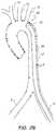
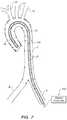
- FIG. 1illustrates a typical diseased aorta ( 2 ) with deposits ( 4 ) clinging to almost all interior surfaces.
- the subject inventionis directed to address such need.
- One embodimentis directed to a method for deploying a device to a distal location across a diseased vessel, comprising inserting a railed expandable sheath into a diseased vessel at a point of entry, the sheath defining a lumen there-through and comprising two or more longitudinal rail structures coupled to a sheet-like member, the sheath having a collapsed configuration, wherein the sheath has a first cross-sectional outer diameter defines a first lumen inner diameter, and an expanded configuration, wherein the sheath has a second cross-sectional outer diameter and second lumen inner diameter, such that in the collapsed configuration, the sheath is configured to be advanced across at least a portion of the diseased vessel to a position adjacent the distal location without substantial size interference between the first cross-sectional outer diameter of the sheath and an inner diameter profile of a lumen of the diseased vessel; and upon positioning the collapsed configuration to the desired position relative to the distal location, the sheath may be expanded to the expanded configuration with incremental pushing of
- the methodfurther may comprise deploying an emboli filter into the diseased vessel at a location opposite of the sheath point of entry from the distal location.
- the methodfurther may comprise deploying one or more emboli filters into the diseased vessel to capture emboli which may exit the diseased vessel to associated tributary vessels.
- the methodfurther may comprise observing one or more radiopaque markers which may be coupled to one or more locations upon the sheath using fluoroscopy while inserting the railed expandable sheath, the markers being configured to be associated with a designated anatomical structure comprising the diseased vessel.
- the sheet-like membermay comprise one or more porous regions configured to allow blood to flow from a position within the lumen to a position across the sheet-like member and outside of the sheath, and inserting may comprise positioning the one or more porous regions adjacent one or more anatomical structures.
- the one or more porous regionsmay be configured to be aligned with tributary vessels that join the diseased vessel.
- the methodfurther may comprise examining a flow pattern adjacent the sheath and designated anatomical structure using Doppler ultrasonic analysis.
- the ultrasonic analysismay be conducted using a transcutaneous ultrasound transducer.
- the ultrasonic analysismay be conducted using an intravascular ultrasound transducer which may be coupled to an elongate probe configured to be placed through the lumen of the sheath.
- Inserting the devicemay comprise pressing one or more surfaces of the device against exposed portions of the rail structures of the sheath to move the rail structures away from each other into the expanded configuration as the device is advanced.
- the methodfurther may comprise inserting a balloon dilatation probe into the lumen to complete the reconfiguration of the railed expandable sheath from the collapsed configuration to the expanded configuration.
- the railed expandable sheathmay be self-expanding from the collapsed configuration to the expanded configuration, and the method further may comprise removing a removable expansion retention member configured to retain the railed expandable sheath in the collapsed configuration.
- the expansion retention membermay comprise a corset and tensile member assembly, and the method further may comprise tensioning the tensile member proximally to release the corset and allow expansion to the expanded configuration.
- the methodfurther may comprise inserting a guidewire through the diseased vessel and using the guidewire to assist with guiding the sheath by advancing the lumen over the guidewire.
- One or more portions of the rail structuresmay comprise a ferromagnetic material, and the method further may comprise passing a magnetic probe through the lumen of the expanded configuration to assist with affirmative collapsing of the sheath back to the collapsed configuration.
- One or more portions of the rail structuresmay comprise a ferromagnetic material, and the method further may comprise retaining a magnetic probe through the lumen of the expanded configuration to maintain the collapsed configuration until transformation to the expanded configuration is desired.
- the methodfurther may comprise retracting the sheath out of the point of entry. Inserting the railed expandable sheath may comprise manually manipulating a proximal portion of the sheath to advance the sheath into the diseased vessel. Inserting the railed expandable sheath may comprise manually advancing an elongate probe that is coupled to the railed expandable sheath relative to the diseased vessel.
- the sheathmay comprise two diametrically opposed rail structures coupled to the sheet-like member.
- the sheathmay comprise three rail structures distributed circumferentially equidistantly.
- the sheathmay comprise four rail structures distributed circumferentially equidistantly.
- the first lumen inner diametermay be equal to between about 0 mm and about 3 mm.
- the second lumen inner diametermay be equal to between about 6 mm and about 8 mm.
- the rail structuresmay comprise a material selected from the group consisting of: polyethylene, ultra-high-molecular weight polyethylene, polyethylene terephthalate, polyoxymethylene, polytetrafluoroethylene, and co-polymers thereof.
- the rail structuresmay comprise Nitinol alloy.
- the rail structuresmay be coated with a lubricious coating.
- the sheet-like membermay comprise a material selected from the group consisting of: polyethylene, polytetrafluoroethylene, and co-polymers thereof.
- the diseased vesselmay be an aorta.
- the devicemay be an implantable prosthesis.
- the implantable prosthesismay be a cardiac valve.
- the distal locationmay be a location within a heart coupled to the diseased vessel.
- the sheathmay be placed across substantially the full length of the aorta between the point of entry and a heart coupled to the aorta.
- the sheathmay be placed across only a portion of the length of the aorta between the point of entry and a heart coupled to the aorta.
- the sheathmay be placed up to, but not across, the carotid artery takeoffs from the aorta.
- the point of entrymay be in a femoral artery coupled to the aorta, and the first cross-sectional outer diameter may be configured to accommodate insertion through the femoral artery.
- Expanding the sheath to the expanded configurationmay comprise unwinding a built up twisting configuration that has been created to maintain the collapsed configuration.
- FIGS. 1A-1Billustrate various portions of a diseased aorta.
- FIGS. 2A-2Fillustrate aspects of a conventional interventional device deployment through a diseased aorta.
- FIGS. 3A-3Z-4illustrate various aspects of an inventive expandable railed sheath that may be used in conducting various cardiovascular procedures, such as a percutaneous aortic valve replacement procedure.
- FIGS. 4A-4Hillustrate aspects of a configuration similar to that of FIGS. 3A-3Z-4 , wherein a branch vessel protection filter is also incorporated.
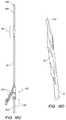
- FIGS. 5A-5Killustrate aspects of a configuration similar to that of FIGS. 3A-3Z-4 , wherein a tubular branch vessel protection filter is also incorporated.
- FIG. 6illustrates a configuration wherein a magnetic probe is utilized to collapse a sheath after an intervention has been conducted through an expanded form of the sheath.
- FIG. 7illustrates a configuration wherein a magnetic probe is utilized to retain a sheath in a collapsed form until an expansion to an expanded form is desired.
- FIGS. 8A-8Gillustrate aspects of a configuration similar to that of FIGS. 3A-3Z-4 , wherein a distal protection filter is also incorporated.
- FIG. 9illustrates aspects of a configuration similar to that of FIGS. 3A-3Z-4 , wherein only a proximal portion of the main vessel is protected by an embodiment of the inventive sheath.
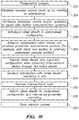
- FIG. 10illustrates various aspects of a deployment technique in accordance with the present invention.
- FIG. 11illustrates various aspects of a deployment technique in accordance with the present invention.
- FIG. 12illustrates various aspects of a deployment technique in accordance with the present invention.
- FIG. 13illustrates various aspects of a deployment technique in accordance with the present invention.
- FIG. 14illustrates various aspects of a deployment technique in accordance with the present invention.
- FIG. 15illustrates various aspects of a deployment technique in accordance with the present invention.
- FIG. 16illustrates various aspects of a deployment technique in accordance with the present invention.
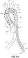
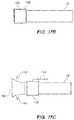
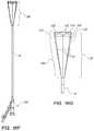
- FIGS. 17A-17Cillustrate aspects of an embodiment of a railed sheath having a frustoconical distal portion configured to interface with a cardiovascular cavity.
- FIGS. 18A-18Jillustrate various aspects of an inventive expandable railed sheath that may be used in conducting various cardiovascular procedures, such as a percutaneous aortic valve replacement procedure.
- FIG. 19illustrates various aspects of a deployment technique in accordance with the present invention.
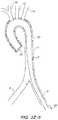
- FIG. 1Ban illustrative representation of a diseased aorta ( 2 ) is shown with deposits ( 4 ) distributed in several locations, including adjacent or within the left ( 6 ) and right ( 8 ) iliac arteries, and adjacent the junctions of the aortic arch with the left subclavian ( 10 ), left common carotid ( 12 ), and innominate artery ( 14 ).
- Navigating a diseased aorta ( 2 )such as that depicted is indeed a challenge with conventional intravascular diagnostic and/or interventional hardware.
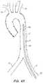
- FIGS. 2A-2Fa conventional instrument deployment is illustrated to demonstrate the disease-related challenges. Referring to FIG.
- the elongate instrument ( 46 )is advanced in a retrograde direction through the aorta ( 2 ) distal tip ( 50 ) first.
- the instrument ( 46 )may be a valve deployment member or probe, a catheter or conduit for conducting various interventions, etc.
- the distal end ( 50 )may become a scraping interface ( 48 ) as it is urged past and against the tissue comprising the diseased aorta ( 2 ), and may accidentally and undesirably cause one or more pieces of the deposit material ( 4 ) to become loose and thereby flowing distally—perhaps into the brain or another undesirable deposit flow location.
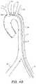
- FIG. 2Cshows that at the relatively extreme turning portions of the aortic arch, a conventional instrument may find itself located immediately adjacent or within the takeoff junctions of the joining arteries ( 10 , 12 , 14 ), where plaques and other deposits may be particularly mechanically vulnerable.
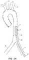
- FIGS. 2D-2Fillustrate further advancement of the instrument ( 46 ) until the distal tip ( 50 ) is in the desired location for the planned diagnostic or interventional procedure.
- the instrumentationis typically retracted, causing yet another scraping interface type of interaction as the instrumentation is pulled proximally in a pathway opposite to that described in reference to FIGS. 2A-2F , and additional risks for undesirable complication related to such interaction.
- FIGS. 3A-3Z-4various aspects of deployment steps and configurations utilizing embodiments of the inventive expandable railed sheath are illustrated.
- a collapsed configuration ( 16 ) of a railed sheathis being inserted ( 80 ) distal tip ( 52 ) first.
- This collapsed configuration ( 16 )may be inserted over a guidewire using conventional “over-the-wire” technique to assist in guiding the collapsed sheath configuration.
- the collapsed configuration ( 16 )leaves much more room in the diseased aorta ( 2 ), thereby decreasing the likelihood of a scraping type mechanical interface relationship as described in reference to FIGS.
- the railed sheathmay comprise one or more pullwires to facilitate steering by an operator as the collapsed railed sheath ( 16 ) is advanced through the diseased aorta ( 2 ) using imaging modalities such as transcutaneous ultrasound and/or fluoroscopy to assist with the interactive steering of such configuration through the diseased vessel.
- imaging modalitiessuch as transcutaneous ultrasound and/or fluoroscopy to assist with the interactive steering of such configuration through the diseased vessel.
- the distal tip ( 52 ) of the collapsed configuration ( 16 )has reached the desired interventional location (here the aortic outflow tract of the left ventricle cavity of the heart) in a minimally invasive way taking advantage of the relatively small cross-sectional size of the collapsed configuration ( 16 ).
- the desired interventional locationhere the aortic outflow tract of the left ventricle cavity of the heart
- FIG. 3C and 3Dclose up views of the collapsed configuration ( 16 ) are illustrated to show that the railed sheath indeed comprises a plurality of elongate rail structures ( 20 ; in the depicted embodiment 4 independent rail structures) coupled together by a sheet or sheet-like member ( 22 ) which, in the depicted collapsed configuration ( 16 ) is folded in between the elongate rail structures ( 20 ).
- a lumen ( 24 )is defined through the railed sheath, and remains relatively small in diameter with the collapsed configuration ( 16 ).
- FIGS. 3E-3Qvarious configurations of railed sheath embodiments are illustrated in cross-sectional views.
- One key core functionality of each of the illustrative embodiments described hereinis the notion of protecting surrounding vascular and other anatomy by providing an intermediate surface between relatively large items to be moved through the vasculature (i.e., such as elongate tools, collapsed prostheses, etc.) and the vasculature itself.
- the intermediate surface, or protective sheathgenerally comprises a sheet-like member that is reinforced by a plurality of generally longitudinal rail members that are configured to de-concentrate loads applied from the inside of the sheath toward the nearby vascular anatomy—in a manner somewhat akin to the manner in which point loads from train wheels on a railroad track are de-concentrated by the rails of the railroad track and absorbed over a large surface provided by the substrate underlying the railroad track.
- This load de-concentrationis believed to provide protection of the underlying anatomy from focused loads that could dislodge plaques or other particles, or create emboli—either from the focused load interface itself, or from any scraping or abrading interfacing that may be related to conventionally pushing a piece of hardware past the unprotected anatomy, as in FIGS. 2A-2F .
- an expanded form ( 26 ) of a railed sheath embodimentis shown having four elongate rail members distributed approximately equidistantly about the circumference of the expanded form ( 26 ).
- the expanded formhas an approximately circular outer shape and defines an approximately circular inner lumen.
- the elongate rail structuresthemselves have elliptical cross-sectional shape profiles ( 20 ) configured to atraumatically and easily accommodate sliding of another diagnostic or interventional device through the lumen during a medical procedure such as a percutaneous valve replacement.
- FIG. 3Fillustrates one configuration of the same hardware as shown in FIG.
- FIG. 3Gillustrates another configuration wherein the sheet-like member ( 22 ) is folded in one direction (i.e., to find mechanical support for slack portions on the next adjacent rail structure 20 in one direction as shown).
- Either of the collapsed configurations illustrated in FIGS. 3F and 3Gmay be suitable for deployment as in FIGS. 3A and 3B . Referring to FIGS.
- FIG. 3H-3Mvarious expanded configuration ( 26 ) embodiments are depicted to illustrate that a great variety of combinations and permutations of hardware subcomponentry is within the scope of the invention.
- four elliptical rail structures ( 20 )are coupled to the outer aspect of a substantially tubular sheet-like member ( 22 ), for example, with polymer welding, adhesive, suturing, or other coupling configuration.
- elongate rail structures of circular cross-section ( 32 )may be utilized for a more uniform bending modulus configuration
- elongate rail structures of rectangular or square cross-section ( 34 )may be utilized to present preferred bending axes to the overall structure of the railed sheath.
- FIGS. 3K-3Membodiments similar to those illustrated in FIGS. 3H-3J are depicted, with exception that the embodiments of FIGS. 3K-3M have the elongate rail structures ( 20 , 32 , 34 , respectively) more tightly integrated into the outer and inner shape of the overall structure (i.e., the outer aspects of the rail structures don't protrude out as much). This may be accomplished, for example, by co-forming the rails ( 20 , 32 , 34 , respectively) from the same bulk material as the sheet-like members ( 22 ), or at least partially encapsulating the rails ( 20 , 32 , 34 , respectively) with the sheet-like member ( 22 ) material. Referring back to the embodiment of FIG.
- various embodimentsmay be created to have a substantially smooth outer shape in the expanded state, and to have the elongate rail structures ( 20 ) protrude more into the inner lumen of the overall structure, which may be desired for mechanically guiding various portions of the diagnostic and/or interventional hardware that may be passed through the working lumen for the medical procedure.
- FIGS. 3N-3Qvarious configurations are shown to illustrate that cross-sectional homogeneity is not only not necessary, but may not be preferred in some scenarios.
- FIG. 3None expanded configuration ( 26 ) is shown wherein a sheet-like member ( 22 ) couples two elliptical rail structures ( 20 ) and two circular rail structures ( 32 ).
- FIG. 3Oa less cross-sectionally homogeneous configuration is shown having two elliptical rail structures ( 20 ) coupled to the sheet-like member ( 22 ) diametrically across from each other, and a circular rail structure ( 32 ) diametrically opposed from a rectangular ( 34 ) rail structure at an angle so that the four depicted rail structures are not uniformly distributed about the circumference of the depicted cross-section.
- three rectangular rail structures ( 34 )are equidistantly circumferentially distributed about the cross-section.
- a group of triangular ( 36 ), elliptical ( 20 ), and rectangular ( 34 ) rail structuresis not equidistantly circumferentially distributed about the cross-section.
- the various cross-sectional permutations and combinationsmay be selected to improve deliverability, to have selected overall shape bending moduli, and to improve utility of the working lumen for passing through diagnostic and/or interventional tools during a medical procedure.
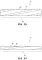
- FIGS. 3R-3VSeveral such configurations are illustrated in FIGS. 3R-3V .
- a longitudinally uniform configurationhas the same cross-sectional configuration of rail structures ( 20 ) and sheet-like member ( 22 ) all along its length.
- FIGS. 3San embodiment is shown wherein the outer shape of the overall structure does not change longitudinally, but wherein one or more of the rail structures ( 20 ) are tapered in shape ( 38 ) longitudinally, to provide greater overall bending modulus for the catheter at the end with the more tapered rail structures.
- FIG. 3Tan embodiment is depicted which has not only one or more tapered ( 38 ) rail structures ( 20 ), but also a tapered ( 40 ) overall outer shape. Such a configuration would have inner lumen size limitations, but would provide greater overall bending modulus for the catheter at the end with the more tapered rail structures and overall shape.
- the rail structuresmay be angularly oriented relative to the longitudinal axis of the overall shape.
- one or more of the rail structures ( 20 )have a spiral orientation ( 42 ).
- FIG. 3Vshows that the same embodiment as shown in FIG. 3U may be collapsed into a collapsed configuration ( 16 ), with the spiral orientation ( 42 ) of the one or more rail structures retained, but to a lesser spiraling angle relative to the longitudinal axis of the overall shape.
- the transition between collapsed configuration ( 16 ) and expanded configuration ( 26 )may be accomplished by advancing a diagnostic and/or interventional instrument ( 44 ) through the lumen of the railed sheath. As shown in FIG. 3W , the proximal portion of the railed sheath through which the instrument ( 44 ) has been advanced are in the expanded configuration ( 26 ), while the distal portion which has not yet been reached by the instrument ( 44 ) remains in the collapsed configuration ( 16 ).
- the railsare specifically configured to assist in maintaining the orientation of the instrument ( 44 ) relative to the railed sheath and associated tubular anatomy as the instrument ( 44 ) is advanced through the railed sheath, to ensure that a predictable orientation is maintained when the instrument ( 44 ) reaches the desired diagnostic and/or interventional tissue theater.
- a percutaneous valve replacement procedureit is highly desirable to make sure that the valve prosthesis gets to the desired location, such as in the aortic outflow tract, in a predictable orientation relative to the structural tissue of the outflow tract, but also that damage is not caused to the patient during the deployment; the subject configurations are designed with such priorities in mind.
- the railed sheathmay be a self-expanding sheath that is affirmatively retained in a collapsed configuration ( 16 ) until a desired time upon which it may be controllably converted to the expanded configuration ( 26 ).
- a corset-style collapse-retention member with a releasable (i.e., by proximal tension) tensile membermay be utilized to retain the collapsed configuration, as in International PCT Publication No. WO 97/21403, which is incorporated by reference herein in its entirety.
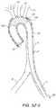
- an expanded configuration of a railed sheath ( 26 )may comprise one or more porous regions ( 132 ) configured to be positioned adjacent tributary vessels to maintain flow through such vessels when the expanded railed sheath is in place.
- a porous region ( 132 )is configured in this embodiment to ensure that flow coming into the distal tip ( 52 ) of the expanded railed sheath ( 26 ) is at least partially diverted up the associated tributary vessels ( 10 , 12 , 14 ) to supply the brain of the patient with blood during the procedure.
- the margins of the porous regionmay be marked with radiopaque markers to facilitate confirmation of placement of the porous region in a desired configuration relative to the anatomy, and transcutaneous and/or intravascular ultrasound and/or fluoroscopy with contrast agent may be utilized to confirm flow out of the aorta and into important tributary vessels during placement of the railed sheath.
- the porous regionfunctions not only as a flow bypass, but also as a filter to capture any deposits or emboli that are being routed through the railed sheath; this may be accomplished by sizing the pores of the porous region to be large enough to pass blood plasma and red blood cells, but small enough to not pass typical emboli and deposits.
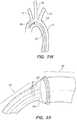
- the distal end of the railed sheathcomprises a trumpet or frustoconical shape ( 140 ) configured to maximize the likelihood that emboli or deposits that exit the adjacent anatomy (here the aortic outflow tract of the left ventricle cavity of the heart 138 ) by providing a more contoured fit of the adjacent anatomy.
- the flared distal frustoconical portion ( 140 )may be retained in a compressed form by a movable or slideable cuff member ( 142 ), which, as shown in FIG. 17C , may be retracted ( 144 ) proximally to allow the flared distal frustoconical portion ( 140 ) to be expandable or expanded ( 146 ) into the adjacent anatomy.
- an elongate insertion device ( 56 )is shown inserting a diagnostic and/or interventional device ( 54 ), such as a collapsed aortic valve prosthesis, toward the desired anatomical location using the subject railed sheath.
- a diagnostic and/or interventional device ( 54 )such as a collapsed aortic valve prosthesis
- the elongate insertion device ( 56 )may be safely retracted ( 58 ) back out through the expanded configuration ( 26 ) of the railed sheath.
- the railed sheathmay be removed by pulling proximally ( 60 ) on the sheath and retracting it out, as shown in FIGS. 3 -Z 3 and 3 -Z 4 .
- the sheathmay be forcibly converted from expanded configuration ( 26 ) to collapsed configuration ( 16 ) for removal, using, for example, an electromagnetic collapsing device. With all of the instrumentation removed, the access wound (for example, to one of the femoral arteries) may be closed and the procedure completed.
- a separate filtering devicesuch as that sold under the tradename Embrella® by Edwards Lifesciences, Inc., may be utilized to assist in preventing unwanted particles or emboli from entering certain tributary vessels.
- a collapsed filtering device( 68 ) may be advanced ( 62 ) with an elongate deployment member ( 66 ).
- the filtering devicemay be converted to an expanded configuration ( 70 ) wherein one or more wings ( 72 , 74 ) form filtrating barriers across one or more tributary vessels ( 12 , 14 ) and are temporarily retained in place by a retainer member ( 76 ).
- the deployment member ( 66 )may be retracted ( 78 ), and as shown in FIG. 4D , a collapsed railed sheath configuration ( 16 ) may be advanced ( 80 ).
- the collapsed railed sheath configuration ( 16 )may be utilized as in reference to FIGS. 3A to 3Z-4 above, but with the temporary filter device in place.
- an elongate recapture device ( 56 )may be inserted ( 62 ) to recapture the filtration device ( 64 ), as shown in FIGS. 4F and 4G , followed by retraction ( 58 ) and completion of the case.
- a tubular filtermay be deployed before installation of a railed sheath to assist with filtering protection at one or more tributary vessel junctions.
- an elongate deployment member ( 88 ) removably coupled to a collapsed tubular filter ( 84 )may be advanced ( 90 ) toward the anatomic location of interest, using, for example, fluoroscopic and/or ultrasound imaging guidance, which may be assisted by radiopaque markers on the filter ( 84 ) and/or deployment member ( 88 ), and/or the injection of imaging contrast agent.
- the tubular filtermay be converted to the expanded configuration depicted in FIG. 5C , using, for example, a balloon expansion element of the deployment member, or a release of a constraining member that retains a self-expanding configuration of the tubular filter until expansion is desired, after which the restraint is released and expansion ensues to the expanded configuration ( 86 ) of the tubular filter, which is configured to screen emboli and/or unwanted particles from entering the associated tributary vessels ( 10 , 12 , 14 in the depicted example).
- the deployment member ( 88 )may be removed ( 92 ), as shown in FIG.
- a collapsed railed sheath configuration ( 16 )may be inserted ( 80 ) through the expanded tubular filter ( 86 ), as shown in FIGS. 5E and 5F , to conduct a procedure in similar fashion as described above in reference to FIGS. 3A to 3 -Z 4 (in one embodiment the porosity of the porous portion ( 132 ) may be increased to maximize flow, since an additional filter is already in place; in another embodiment the porous portion ( 132 ) may simply comprise an open window section of the railed sheath).
- the railed sheath ( 26 )may be removed ( 60 ), and as shown in FIG.
- the filter deployment member ( 88 )may be advanced to recapture the filter and pull it proximally out ( 92 ), causing it to slightly collapse and become mobile relative to the anatomy.
- two or more pullwires ( 94 , 96 )may be coupled to the tubular filter (either intraoperatively, or preoperatively and left in place during the procedure with leads to a proximal manual access point) and utilized to forcibly dislodge the tubular filter for withdrawal by causing radial collapse of at least a proximal portion ( 98 ) of the tubular filter ( 86 ) as it is pulled toward the small aperture of the deployment member ( 88 ) through which the pullwires or tether lines ( 94 , 96 ) exit to couple to the filter.
- a distal portion of an electromagnetic deployment probe ( 100 )may be configured to controllably attract ferromagnetic portions of the tubular filter to draw the filter back into a collapsed state when a voltage source ( 104 ) provides electromagnetic attraction toward one or more electromagnets coupled to the distal portion ( 102 ) of the electromagnetic deployment probe ( 100 ).
- the tubular filtermay be retracted and removed.
- a deployment probe ( 106 ) with a longer electromagnetic portion than that of FIG. 5Kmay be utilized to assist in the affirmative re-collapsing of a railed sheath embodiment that comprises ferromagnetic portions which may be controllably attracted toward the electromagnetic deployment probe ( 106 ) using an operatively coupled voltage controller ( 108 ).
- the voltage controller ( 108 )may be configured to activate all of the electromagnets on the probe ( 106 ) simultaneously to re-collapse the associated length of the railed sheath simultaneously.
- controller ( 108 )may be configured to sequentially activate (and retain activation until release is desired) the various electromagnets comprising the probe to provide for a sequential longitudinal collapsing of the associated railed sheath (i.e., from the most proximal portion to the most distal portion, vice versa, etc.).
- a deployment probe ( 106 ) similar to that depicted in FIG. 6may be utilized to forcibly retain a collapse configuration until sequential or simultaneous expansion of all portions of the railed sheath is desired.
- the magnet controller ( 108 )may be configured to retain the collapsed state of the entire exposed length of the railed sheath during insertion.
- the magnet controllermay be configured to either simultaneously or sequentially release portions of the railed sheath to allow for expansion to the expanded form ( 26 ). Completion of expansion to the expanded form ( 26 ) may be completed as a result of a self-expanding infrastructure of the railed sheath, with the help of an expandable balloon, etc.
- a proximal filtermay be placed proximal to the access point for the aforementioned hardware embodiments to prevent particles or emboli from flowing distally.
- a close up view of an access point ( 110 , such as an arteriotomy) and associated vessels ( 6 , 8 ) and deposits ( 4 )is shown with a collapsed filtration device ( 112 ) being advanced ( 116 ) with a deployment member ( 114 ) through the access point ( 110 ).
- the deployment member ( 114 )may be shaped such that the collapsed filtration device ( 112 ) can be tucked immediately proximal of the access point ( 110 ).
- the filtration devicemay be self-expanding or expandable (i.e., with a balloon) to be controllably converted into an expanded/deployed configuration ( 120 ) wherein blood flow ( 124 ) is directed across a filter mesh ( 112 ) portion of the expanded filter ( 120 ) to prevent passage of emboli, particles, and the like.
- the filter ( 120 )has a tether member ( 126 ) which may be extended out of the access point ( 110 ) and used subsequently for recapture and removal of the filter.
- a collapsed railed sheath ( 16 )may be advanced and utilized as in the embodiments described in reference to FIGS. 3A to 3Z-4 , with the further benefit of the distal protection filter in place.
- the railed sheath ( 26 )may be retracted ( 60 ) past the still-deployed filter ( 120 ), as shown in FIG. 8F , after which the tether member ( 126 ) may be utilized to assist in retraction ( 128 ) of the filter member out of the access point ( 110 ) and completion of the procedure.
- a railed sheathmay be utilized to only partially protect a route to a targeted anatomical position for a diagnostic and/or interventional instrument.
- a railed sheath26
- the instrumentation56 , 54
- the remainder of the length of the vesselto the targeted anatomy without the protection and/or mechanical guidance of the railed sheath.
- a guidewire and/or introducer sheathmay be advanced across the access location to provide for guidance and support of additional instrumentation which may be advanced ( 306 ).
- a compressed configuration of a railed sheathmay be advanced—for example, over-the-guidewire and through the introducer sheath—in a compressed configuration ( 308 ).
- the railed sheathmay be expanded or allowed to expand to, for example, accommodate passage of an advancing interventional device (such as a percutaneous valve deployment assembly) across the railed sheath to the anatomical location of interest ( 312 ).
- an advancing interventional devicesuch as a percutaneous valve deployment assembly
- the proceduremay be conducted ( 314 ), after which the tools may be retracted ( 316 ), the railed sheath returned to a collapsed or partially collapsed configuration (for example, by simple proximal tensioning to partially collapse the railed sheath, by electromagnet-induced force to fully collapse the railed sheath, etc.) ( 318 ), and vascular access closed ( 320 ) to complete the procedure.
- the toolsmay be retracted ( 316 )
- the railed sheathreturned to a collapsed or partially collapsed configuration (for example, by simple proximal tensioning to partially collapse the railed sheath, by electromagnet-induced force to fully collapse the railed sheath, etc.) ( 318 ), and vascular access closed ( 320 ) to complete the procedure.
- a folding embolic filtermay be advanced ( 322 ) and deployed ( 324 ) prior to introduction of the railed sheath ( 308 ); this filter may be reconfigured into a collapsed transport configuration ( 326 ) and retracted ( 328 ) before final closing of the vascular access ( 320 ).
- a tubular embolic filtermay be advanced ( 330 ) and deployed ( 332 ) prior to introduction of the railed sheath ( 308 ); this filter may be reconfigured into a collapsed transport configuration ( 334 ) and retracted ( 336 ) before final closing of the vascular access ( 320 ).
- the railed sheathmay be returned to a compressed configuration with the help of magnet-induced loads from a magnetic probe or portion of a probe ( 338 ) before retraction using the probe ( 340 ).
- FIG. 14an embodiment similar to that of FIG. 10 is illustrated, with the exception that for railed sheath introduction, the collapsed configuration is actively maintained using magnetic loads ( 342 ), and expansion ( 344 ) to the expanded configuration after appropriate longitudinal advancement ( 310 ) is controllably facilitated by controllably decreasing or removing the magnetic loads, followed by retraction of the magnetic tool ( 346 ) and advancement of the interventional or diagnostic tools through the railed sheath ( 348 ).
- a proximal filter, or “distal protection device”is installed ( 350 ) proximally; this filter may be removed ( 352 ) after ultimate removal of the railed sheath ( 318 ).
- railed sheathmay be only partially positioned across the length of the vascular route to the targeted anatomy (i.e., rather than protecting the entire length with a railed sheath, only a portion, such as a proximal portion, may be protected) ( 354 ).
- the rail structuresmay comprise various bio-compatible metals, such as titanium, alloys thereof such as Nitinol superalloy, and/or polymers such as polyethylene, ultra-high-molecular weight polyethylene, polyethylene terephthalate, polyoxymethylene, polytetrafluoroethylene, and co-polymers thereof.
- bio-compatible metalssuch as titanium, alloys thereof such as Nitinol superalloy
- polymerssuch as polyethylene, ultra-high-molecular weight polyethylene, polyethylene terephthalate, polyoxymethylene, polytetrafluoroethylene, and co-polymers thereof.
- the sheet-like membermay comprise a material such as polyethylene, polytetrafluoroethylene, or co-polymers thereof.
- a vacuum devicesuch as a syringe may be operatively coupled to the configuration (for example, coupled to or integrated into a proximal handle that forms a manual interface for inserting a railed sheath catheter), and may have an elongate distal portion that may be inserted into a deployed railed sheath catheter to vacuum away emboli that may be present.
- FIGS. 18A-18Jvarious aspects of another embodiment of an intervention protection configuration are shown, wherein a distal portion of the delivery configuration is allowed to expand relative to a more proximal portion which may remain substantially more contracted or collapsed.
- a railed sheath in a collapsed configuration16
- transvascular accessthrough a portion of the associated vasculature such as the left iliac artery ( 6 )
- the instrument assemblyinto a position as shown wherein the distal tip is located in a preferred location, such as adjacent an aortic valve of the patient.
- a proximal portion of the instrumentation, including a proximal control assembly ( 150 )remains external to the vascular access for manipulation and control of the procedure, along with optional external drainage or exit of fluids or emboli or other materials which may collect within the instrumentation.
- the depicted embodimentcomprises an atraumatic obturator tip ( 148 ) selected to reduce the results of impacts that such distal instrumentation may have during insertion and placement.
- the assemblymay comprise a collapsed railed sheath portion ( 16 ) removably coupled to a distal obturator jacket assembly ( 168 ) which has an atraumatic tip ( 148 ).
- the obturator jacket assembly ( 168 )preferably is coupled, through the lumen of the sheath and proximally out through a valved ( 154 ) port ( 156 ) defined through the tubular body assembly ( 164 ) of the proximal assembly ( 150 ), to an elongate obturator coupling member ( 152 ) which may be movably positioned through a central working lumen of the sheath (such as that referred to as element 24 above).
- the depicted proximal assembly ( 150 )also comprises a second valved ( 158 ) port ( 160 ) which may be occupied by a portion of a sheath tip manipulation assembly, which may comprise a proximal manipulation structure or handle ( 162 ) which is coupled to a distal portion of the sheath using a movable tension-applying element such as a pullwire.
- a movable tension-applying elementsuch as a pullwire.
- an operatormay manually manipulate, or pull, the proximal manipulation structure ( 162 ) to tension the movable tension-applying element and cause closure of the distal tip of the sheath using a hoop configuration.
- the obturator jacket assemblymay be configured to assist in temporarily maintaining a collapsed configuration of a distal portion of the sheath, and may be configured to extend the full length of a particularly expandable portion of the sheath which may be expanded outward subsequent to removal of the obturator-jacket assembly ( 168 ) from its collapse restraint configuration as shown in FIG. 18B .
- a particularly expandable portion of the sheathwhich may be expanded outward subsequent to removal of the obturator-jacket assembly ( 168 ) from its collapse restraint configuration as shown in FIG. 18B .
- the obturator-jacket assembly ( 168 )may be advanced or urged ( 166 ) distally relative to the remainder of the sheath assembly ( 16 , 150 ), causing the obturator jacket assembly ( 168 ), with its atraumatic distal tip ( 148 ), to become released from the remainder of the sheath assembly ( 16 , 150 ) with such advancement.
- such distal advancementcauses a thin jacket-like wrapper portion of the obturator-jacket assembly ( 168 ) to become torn or fractured along a predetermined pathway (i.e., via preexisting perforations created in the jacket-like wrapper portion) in a manner that substantially releases and decouples the underlying collapsed portions of the railed sheath assembly from the jacket-like wrapper portion (while the jacket-like wrapper portion remains firmly attached to the obturator tip 148 ), allowing a portion of the sheath to self-expand to an expanded configuration ( 26 ) as shown in FIG. 18C and the close-up view of FIG. 18D .
- a predetermined pathwayi.e., via preexisting perforations created in the jacket-like wrapper portion
- the distal portion of the railed sheathmay be allowed to become fully expanded ( 26 ), and then the obturator assembly ( 168 , 152 ) may be pulled proximally ( 170 ) through the lumen of the sheath ( 24 ) and through the proximal assembly ( 150 ) where it may be removed.
- this embodiment of the railed sheathis in an expanded configuration wherein a proximal portion of the railed sheath remains in a relatively collapsed or small diameter configuration ( 16 ) as compared with the expanded distal portion ( 26 ), which features a plurality of structural rail members ( 32 ) configured to self-expand and support a tubular or frustoconical porous filter mesh ( 132 ) surface configured to capture particles that may enter it, such as clots or plaque particles.
- the expanded distal portionmay be selected to have a length approximately equivalent to the arcuate length of the subject aortic arch.
- the embodiment depicted in close-up view in FIGS. 18G-18Hfeatures six elongate structural rail members ( 32 ) which may comprise a material such as a nickel titanium Nitinol superalloy; other embodiments may feature 4 , 5 , 7 , 8 , 9 , 10 , 11 , 12 , or more rail members ( 32 ), which may be configured to be prominent either to the inner surface or outer surface of the expanded portion ( 26 ), and may be configured to have various cross-sectional areas and/or positions, as in the embodiments described above in reference to FIGS.
- the most distal portion of the expanded sheath portion ( 26 )may comprise a vessel engagement portion ( 172 ) selected to maximize physical accommodation of local endovascular geometry and/or terrain, so that particles moving through the pertinent vessel are biased to be captured by the railed sheath, not diverted around it.
- the depicted vessel engagement portioncomprises a relatively low-modulus sheet-like material, which may comprise a thin biocompatible polymer, coupled in a cylindrical fashion to a relatively low-modulus zig-zag structure ( 176 ) intercoupled between two relatively low-modulus hoops ( 184 , 186 ).
- a controllably collapsible hoop ( 174 )may be intercoupled into the distal assembly and movably coupled to the proximal manipulation assembly (element 162 of FIG. 18B , for example) to allow an operator to pull upon the proximal manipulation assembly and cause increased hoop tension in the controllably collapsible hoop ( 174 ), causing such hoop to controllably collapse and close the distal assembly into a closed-distal configuration ( 178 ), as shown in FIG.
- the entire expanded portion ( 26 ), such as illustrated in FIG. 18Gis a self-expanding structure, in that it is biased to expand to the expanded configuration ( 26 ) upon release of mechanical constraint such as the aforementioned obturator jacket.
- only a tip portionis a self-expanding structure, such as a tip portion including the distal engagement portion ( 172 ) and a distal subportion of the frustoconical distal portion ( 140 ) of the sheath.
- the removable obturator jacket covering and restraining the underlying compressed distal portion of the sheathmay be removed directly from the outside using a tensile member coupled to the outer surface of the jacket and configured to tear the jacket away from the underlying compressed distal portion of the sheath to allow such compressed distal portion to self-expand.
- the jacket coveringmay be pulled off from the outside using a tensile member, such as a pullwire configured to be manually and controllably tensioned from a proximal location using a handle or other tensioning fixture, coupled between the jacket and a proximal location accessible using the proximal assembly ( 150 ) and pulled proximally away from the sheath in a tear-away fashion prescribed by predetermined patterning (i.e., through perforated tear-away lines or patterns).
- a combination of release/removal from through the working lumen, and release/removal from the outside aspect of the sheath as described immediately abovemay be utilized to fully release the sheath distal end and allow self-expansion.
- the inventive protective configurationsprovide a means for conducting an intervention while also protecting the underlying tissue and related anatomy; further, the railed sheath configurations assist with delivery and alignment of tools and/or prostheses which may be related to the vascular intervention.
- vascular accessmay be established ( 304 ) and a guidewire and/or introducer may be advanced into the subject vessel lumen ( 306 ).
- a protective or railed sheathmay be introduced ( 360 ) and advanced ( 310 ) in a compressed configuration to place the distal portion in a desired position relative to the subject anatomy (for example, in an aortic valve prosthesis deployment configuration, the sheath may be positioned to allow for deployment of the valve prosthesis adjacent the aortic outflow tract of the patient, as planned preoperatively).
- the protective or railed sheathmay be converted to its expanded configuration, which may comprise advancement and then retraction of an obturator assembly, as described above in reference to FIGS. 18A-18J , which may remove a wrapper layer or compression layer coupled to the obturator, thereby allowing the underlying sheath portion to self-expand in a manner akin to that of a self-expanding stent prosthesis ( 362 ).
- intervention stepsmay be conducted which involve insertion and/or retraction of one or more devices, tools, or prostheses through the working lumen defined through the sheath, with protection provided to associated tissues by virtue of such sheath deployment ( 364 ).
- the toolsmay be removed ( 316 ), and the expanded distal portion of the sheath controllably returned to a safe removal configuration wherein at least a distal portion of the sheath is controllably collapsed or closed, such as by a hoop closure actuated by proximally pulling a tension or pullwire, as described above in reference to FIGS. 18A-18J ( 368 ).
- Vascular accessmay then be closed after removal of the sheath assembly ( 320 ).
- kitsmay further include instructions for use and be packaged in sterile trays or containers as commonly employed for such purposes.
- the inventionincludes methods that may be performed using the subject devices.
- the methodsmay comprise the act of providing such a suitable device. Such provision may be performed by the end user.
- the “providing” actmerely requires the end user obtain, access, approach, position, set-up, activate, power-up or otherwise act to provide the requisite device in the subject method.
- Methods recited hereinmay be carried out in any order of the recited events which is logically possible, as well as in the recited order of events.
- lubricious coatingse.g., hydrophilic polymers such as polyvinylpyrrolidone-based compositions, fluoropolymers such as tetrafluoroethylene, hydrophilic gel or silicones
- hydrophilic polymerssuch as polyvinylpyrrolidone-based compositions
- fluoropolymerssuch as tetrafluoroethylene
- hydrophilic gel or siliconesmay be used in connection with various portions of the devices, such as relatively large interfacial surfaces of movably coupled parts, if desired, for example, to facilitate low friction manipulation or advancement of such objects relative to other portions of the instrumentation or nearby tissue structures.
- additional actsas commonly or logically employed.
- any optional feature of the inventive variations describedmay be set forth and claimed independently, or in combination with any one or more of the features described herein.
- Reference to a singular itemincludes the possibility that there are plural of the same items present. More specifically, as used herein and in claims associated hereto, the singular forms “a,” “an,” “said,” and “the” include plural referents unless specifically stated otherwise.
- use of the articlesallow for “at least one” of the subject item in the description above as well as claims associated with this disclosure. It is further noted that such claims may be drafted to exclude any optional element. As such, this statement is intended to serve as antecedent basis for use of such exclusive terminology as “solely,” “only” and the like in connection with the recitation of claim elements, or use of a “negative” limitation.
Landscapes
- Health & Medical Sciences (AREA)
- Life Sciences & Earth Sciences (AREA)
- Engineering & Computer Science (AREA)
- Heart & Thoracic Surgery (AREA)
- Biomedical Technology (AREA)
- Animal Behavior & Ethology (AREA)
- General Health & Medical Sciences (AREA)
- Public Health (AREA)
- Veterinary Medicine (AREA)
- Cardiology (AREA)
- Vascular Medicine (AREA)
- Oral & Maxillofacial Surgery (AREA)
- Transplantation (AREA)
- Biophysics (AREA)
- Hematology (AREA)
- Pulmonology (AREA)
- Anesthesiology (AREA)
- Physics & Mathematics (AREA)
- Pathology (AREA)
- Surgery (AREA)
- Molecular Biology (AREA)
- Medical Informatics (AREA)
- Child & Adolescent Psychology (AREA)
- Human Computer Interaction (AREA)
- Nuclear Medicine, Radiotherapy & Molecular Imaging (AREA)
- Radiology & Medical Imaging (AREA)
- Mechanical Engineering (AREA)
- Surgical Instruments (AREA)
- Media Introduction/Drainage Providing Device (AREA)
- Prostheses (AREA)
- Apparatus For Radiation Diagnosis (AREA)
Abstract
Description
Claims (11)
Priority Applications (2)
| Application Number | Priority Date | Filing Date | Title |
|---|---|---|---|
| US15/228,380US10874511B2 (en) | 2011-11-10 | 2016-08-04 | System for deploying a device to a distal location across a diseased vessel |
| US17/100,724US11751994B2 (en) | 2011-11-10 | 2020-11-20 | System for deploying a device to a distal location across a diseased vessel |
Applications Claiming Priority (5)
| Application Number | Priority Date | Filing Date | Title |
|---|---|---|---|
| US201161558397P | 2011-11-10 | 2011-11-10 | |
| US201161558357P | 2011-11-10 | 2011-11-10 | |
| US201261717575P | 2012-10-23 | 2012-10-23 | |
| US13/673,898US10959844B2 (en) | 2011-11-10 | 2012-11-09 | System for deploying a device to a distal location across a diseased vessel |
| US15/228,380US10874511B2 (en) | 2011-11-10 | 2016-08-04 | System for deploying a device to a distal location across a diseased vessel |
Related Parent Applications (1)
| Application Number | Title | Priority Date | Filing Date |
|---|---|---|---|
| US13/673,898ContinuationUS10959844B2 (en) | 2011-11-10 | 2012-11-09 | System for deploying a device to a distal location across a diseased vessel |
Related Child Applications (1)
| Application Number | Title | Priority Date | Filing Date |
|---|---|---|---|
| US17/100,724ContinuationUS11751994B2 (en) | 2011-11-10 | 2020-11-20 | System for deploying a device to a distal location across a diseased vessel |
Publications (2)
| Publication Number | Publication Date |
|---|---|
| US20160338828A1 US20160338828A1 (en) | 2016-11-24 |
| US10874511B2true US10874511B2 (en) | 2020-12-29 |
Family
ID=48290632
Family Applications (4)
| Application Number | Title | Priority Date | Filing Date |
|---|---|---|---|
| US13/673,911Active2034-06-24US9370438B2 (en) | 2011-11-10 | 2012-11-09 | Method for deploying a device to a distal location across a diseased vessel |
| US13/673,898Active2034-05-06US10959844B2 (en) | 2011-11-10 | 2012-11-09 | System for deploying a device to a distal location across a diseased vessel |
| US15/228,380Active2033-05-09US10874511B2 (en) | 2011-11-10 | 2016-08-04 | System for deploying a device to a distal location across a diseased vessel |
| US17/100,724Active2033-08-13US11751994B2 (en) | 2011-11-10 | 2020-11-20 | System for deploying a device to a distal location across a diseased vessel |
Family Applications Before (2)
| Application Number | Title | Priority Date | Filing Date |
|---|---|---|---|
| US13/673,911Active2034-06-24US9370438B2 (en) | 2011-11-10 | 2012-11-09 | Method for deploying a device to a distal location across a diseased vessel |
| US13/673,898Active2034-05-06US10959844B2 (en) | 2011-11-10 | 2012-11-09 | System for deploying a device to a distal location across a diseased vessel |
Family Applications After (1)
| Application Number | Title | Priority Date | Filing Date |
|---|---|---|---|
| US17/100,724Active2033-08-13US11751994B2 (en) | 2011-11-10 | 2020-11-20 | System for deploying a device to a distal location across a diseased vessel |
Country Status (9)
| Country | Link |
|---|---|
| US (4) | US9370438B2 (en) |
| EP (3) | EP4190387A1 (en) |
| JP (2) | JP2015500681A (en) |
| CN (1) | CN104039381A (en) |
| AU (1) | AU2012335016B2 (en) |
| BR (1) | BR112014012352A2 (en) |
| CA (3) | CA3183330A1 (en) |
| IL (1) | IL232542B (en) |
| WO (1) | WO2013071179A1 (en) |
Cited By (3)
| Publication number | Priority date | Publication date | Assignee | Title |
|---|---|---|---|---|
| US10967152B2 (en) | 2017-03-10 | 2021-04-06 | Abiomed, Inc. | Expandable introducer sheath for medical device |
| US11660434B2 (en) | 2020-02-03 | 2023-05-30 | Abiomed, Inc. | Expandable sheath with interlock dilator |
| US11751994B2 (en) | 2011-11-10 | 2023-09-12 | Medtronic, Inc. | System for deploying a device to a distal location across a diseased vessel |
Families Citing this family (27)
| Publication number | Priority date | Publication date | Assignee | Title |
|---|---|---|---|---|
| US8579964B2 (en) | 2010-05-05 | 2013-11-12 | Neovasc Inc. | Transcatheter mitral valve prosthesis |
| US9308087B2 (en) | 2011-04-28 | 2016-04-12 | Neovasc Tiara Inc. | Sequentially deployed transcatheter mitral valve prosthesis |
| US9554897B2 (en) | 2011-04-28 | 2017-01-31 | Neovasc Tiara Inc. | Methods and apparatus for engaging a valve prosthesis with tissue |
| US11213318B2 (en) | 2011-11-10 | 2022-01-04 | Medtronic Vascular, Inc. | Expandable introducer sheath and method |
| US9345573B2 (en) | 2012-05-30 | 2016-05-24 | Neovasc Tiara Inc. | Methods and apparatus for loading a prosthesis onto a delivery system |
| US9572665B2 (en) | 2013-04-04 | 2017-02-21 | Neovasc Tiara Inc. | Methods and apparatus for delivering a prosthetic valve to a beating heart |
| JP6529485B2 (en) | 2013-05-10 | 2019-06-12 | トランスエオーティック メディカル, インコーポレイテッド | System for deploying a device to a distal location across a diseased vessel |
| CA2912204A1 (en) | 2013-05-17 | 2014-11-20 | Transaortic Medical, Inc. | Expandable introducer sheath |
| EP3288492B1 (en)* | 2015-04-30 | 2024-10-16 | EmStop Inc. | System for implanting a prosthetic aortic valve and an embolic material blocking catheter |
| CA3007660A1 (en) | 2015-12-15 | 2017-06-22 | Neovasc Tiara Inc. | Transseptal delivery system |
| US10433952B2 (en) | 2016-01-29 | 2019-10-08 | Neovasc Tiara Inc. | Prosthetic valve for avoiding obstruction of outflow |
| WO2017153587A1 (en) | 2016-03-10 | 2017-09-14 | Keystone Heart Ltd. | Intra-aortic device |
| AU2017306141A1 (en)* | 2016-08-02 | 2019-03-07 | Aortica Corporation | Systems, devices, and methods for coupling a prosthetic implant to a fenestrated body |
| CA3038970A1 (en)* | 2016-09-29 | 2018-04-05 | Innervate Medical, Llc | Uses of minimally invasive systems and methods for neurovascular signal management including endovascular electroencephalography and related techniques for epilepsy detection and treatment |
| CA3042588A1 (en) | 2016-11-21 | 2018-05-24 | Neovasc Tiara Inc. | Methods and systems for rapid retraction of a transcatheter heart valve delivery system |
| CA3073834A1 (en) | 2017-08-25 | 2019-02-28 | Neovasc Tiara Inc. | Sequentially deployed transcatheter mitral valve prosthesis |
| US11006939B2 (en) | 2017-12-08 | 2021-05-18 | Tendyne Holdings, Inc. | Introducer sheath with seal and methods of using the same |
| CN111902105B (en) | 2017-12-28 | 2023-08-01 | 艾姆斯托普股份有限公司 | Embolic material capture catheter and related devices and methods |
| CN113271890B (en) | 2018-11-08 | 2024-08-30 | 内奥瓦斯克迪亚拉公司 | Ventricular deployment of transcatheter mitral valve prosthesis |
| CA3132873A1 (en) | 2019-03-08 | 2020-09-17 | Neovasc Tiara Inc. | Retrievable prosthesis delivery system |
| CA3135753C (en) | 2019-04-01 | 2023-10-24 | Neovasc Tiara Inc. | Controllably deployable prosthetic valve |
| US11491006B2 (en) | 2019-04-10 | 2022-11-08 | Neovasc Tiara Inc. | Prosthetic valve with natural blood flow |
| US11779742B2 (en) | 2019-05-20 | 2023-10-10 | Neovasc Tiara Inc. | Introducer with hemostasis mechanism |
| JP7520897B2 (en) | 2019-06-20 | 2024-07-23 | ニオバスク ティアラ インコーポレイテッド | Thin prosthetic mitral valve |
| US11707351B2 (en) | 2019-08-19 | 2023-07-25 | Encompass Technologies, Inc. | Embolic protection and access system |
| US11583426B2 (en) | 2020-03-03 | 2023-02-21 | Teleflex Life Sciences Limited | Vessel lining device and related methods |
| WO2024258736A1 (en)* | 2023-06-14 | 2024-12-19 | Walzman Daniel Ezra | Endovascular devices with expandable filter and sheath |
Citations (79)
| Publication number | Priority date | Publication date | Assignee | Title |
|---|---|---|---|---|
| US4655771A (en) | 1982-04-30 | 1987-04-07 | Shepherd Patents S.A. | Prosthesis comprising an expansible or contractile tubular body |
| US4723549A (en) | 1986-09-18 | 1988-02-09 | Wholey Mark H | Method and apparatus for dilating blood vessels |
| US5061275A (en) | 1986-04-21 | 1991-10-29 | Medinvent S.A. | Self-expanding prosthesis |
| US5221261A (en) | 1990-04-12 | 1993-06-22 | Schneider (Usa) Inc. | Radially expandable fixation member |
| WO1995005207A2 (en) | 1993-08-19 | 1995-02-23 | Endovascular Technologies, Inc. | Dual valve reinforced sheath and method |
| US5415664A (en) | 1994-03-30 | 1995-05-16 | Corvita Corporation | Method and apparatus for introducing a stent or a stent-graft |
| US5527282A (en) | 1994-12-09 | 1996-06-18 | Segal; Jerome | Vascular dilatation device and method |
| WO1997021403A1 (en) | 1995-12-14 | 1997-06-19 | Prograft Medical, Inc. | Kink-resistant stent graft |
| WO1998009678A1 (en) | 1996-09-03 | 1998-03-12 | Friedman, Mark, M. | Annular catheter |
| CN1204242A (en) | 1995-10-13 | 1999-01-06 | 血管转换公司 | Methods and devices for bypassing and/or other transvascular procedures for arterial blockages |
| US5863366A (en) | 1995-06-07 | 1999-01-26 | Heartport, Inc. | Method of manufacture of a cannula for a medical device |
| WO1999024102A1 (en) | 1997-11-06 | 1999-05-20 | Heartport, Inc. | Methods and devices for cannulating a patient's blood vessel |
| US5941896A (en) | 1997-09-08 | 1999-08-24 | Montefiore Hospital And Medical Center | Filter and method for trapping emboli during endovascular procedures |
| FR2776114A1 (en) | 1998-03-13 | 1999-09-17 | Fujitsu Ltd | DATA READING METHOD AND APPARATUS |
| US5997508A (en) | 1996-03-28 | 1999-12-07 | Medtronic, Inc. | Expandable percutaneous introducer sheath |
| US6090072A (en) | 1992-10-15 | 2000-07-18 | Scimed Life Systems, Inc. | Expandable introducer sheath |
| US6179851B1 (en) | 1996-07-17 | 2001-01-30 | Scimed Life Systems, Inc. | Guiding catheter for positioning a medical device within an artery |
| US20010041909A1 (en) | 1997-05-08 | 2001-11-15 | Embol-X, Inc. | Methods of protecting a patient from embolization during surgery |
| WO2001091844A1 (en) | 2000-05-31 | 2001-12-06 | Kerberos Proximal Solutions, Inc. | Embolization protection system for vascular procedures |
| US20010053929A1 (en) | 1998-12-09 | 2001-12-20 | Michael J. Vonesh | Multi-stage expandable stent-graft |
| US20020035394A1 (en) | 1998-09-05 | 2002-03-21 | Jomed Gmbh | Methods and apparatus for stenting comprising enhanced embolic protection, coupled with improved protection against restenosis and thrombus formation |
| US20020077598A1 (en) | 1998-10-29 | 2002-06-20 | Yap Darren Y. K. | Improved fluid reservoir piston |
| US20020077596A1 (en) | 1997-05-12 | 2002-06-20 | Embol-X, Inc. | Perfusion shunt apparatus and method |
| WO2002056955A1 (en) | 2001-01-18 | 2002-07-25 | Edwards Lifesciences Corporation | Arterial cannula with perforated filter lumen |
| JP2002336261A (en) | 2001-04-03 | 2002-11-26 | Medtronic Ave Inc | Temporary luminal filter guide wire and its usage |
| US20030050658A1 (en) | 2001-09-13 | 2003-03-13 | Linda Trask | Retaining device for axially restraining movement between tubular elements of a medical device |
| US20030144670A1 (en) | 2001-11-29 | 2003-07-31 | Cook Incorporated | Medical device delivery system |
| WO2003090834A2 (en) | 2002-04-25 | 2003-11-06 | The Board Of Trustees Of The Leland Stanford Junior University | Expandable guide sheath and apparatus and methods using such sheaths |
| US6692462B2 (en) | 1999-05-19 | 2004-02-17 | Mackenzie Andrew J. | System and method for establishing vascular access |
| US6706033B1 (en) | 1999-08-02 | 2004-03-16 | Edwards Lifesciences Corporation | Modular access port for device delivery |
| US20040153117A1 (en) | 2003-01-30 | 2004-08-05 | Clubb Thomas L. | Embolic filters with controlled pore size |
| US20040215167A1 (en) | 2002-08-27 | 2004-10-28 | Amir Belson | Embolic protection device |
| US20040260331A1 (en) | 2003-06-20 | 2004-12-23 | D'aquanni Peter | Beta titanium embolic protection frame and guide wire |
| US20050021125A1 (en) | 1999-11-15 | 2005-01-27 | Stack Richard S. | Stent delivery catheter and method of use |
| US20050216053A1 (en) | 2001-04-03 | 2005-09-29 | Medtronic Vascular, Inc. | Guidewire apparatus for temporary distal embolic protection |
| US20060052750A1 (en) | 2004-09-09 | 2006-03-09 | Jay Lenker | Expandable transluminal sheath |
| US7014647B2 (en) | 1999-05-07 | 2006-03-21 | Salviac Limited | Support frame for an embolic protection device |
| US20060135981A1 (en) | 2004-09-09 | 2006-06-22 | Jay Lenker | Expandable transluminal sheath |
| US20060271093A1 (en) | 2005-05-27 | 2006-11-30 | Holman Thomas J | Fiber mesh controlled expansion balloon catheter |
| US20060282154A1 (en) | 2005-05-24 | 2006-12-14 | Abbott Laboratories | Bifurcation stent delivery catheter assembly and method |
| US20070016280A1 (en) | 2005-07-14 | 2007-01-18 | Cappella, Inc. | Delivery System And Method Of Use For Deployment Of Self-Expandable Vascular Device |
| WO2007106755A1 (en) | 2006-03-10 | 2007-09-20 | Arbor Surgical Technologies, Inc. | Valve introducers and methods for making and using them |
| US20070244501A1 (en) | 2006-04-18 | 2007-10-18 | Horn Daniel J | Medical balloons |
| US20080167705A1 (en) | 2007-01-10 | 2008-07-10 | Cook Incorporated | Short wire stent delivery system with splittable outer sheath |
| US20080188928A1 (en) | 2005-09-16 | 2008-08-07 | Amr Salahieh | Medical device delivery sheath |
| US20080195137A1 (en) | 2004-10-26 | 2008-08-14 | Alleyne Cargill H | Devices and Methods for Aneurysm Treatment |
| US20080243068A1 (en) | 2005-12-29 | 2008-10-02 | Kamal Ramzipoor | Methods and apparatus for treatment of venous insufficiency |
| US20090005675A1 (en) | 2005-05-06 | 2009-01-01 | Sorin Grunwald | Apparatus and Method for Endovascular Device Guiding and Positioning Using Physiological Parameters |
| US20090137900A1 (en) | 2002-10-23 | 2009-05-28 | Medtronic, Inc. | Methods and Apparatus for Locating Body Vessels and Occlusions in Body Vessels |
| US20090182360A1 (en) | 1995-10-13 | 2009-07-16 | Medtronic Vascular, Inc. | Device, System and Method for Interstitial Transvascular Intervention |
| US20090240202A1 (en)* | 2008-03-21 | 2009-09-24 | William Joseph Drasler | Expandable introducer sheath |
| US20090254169A1 (en) | 2008-04-03 | 2009-10-08 | Gardia Medical Ltd. | Delivery catheter with constraining sheath and methods of deploying medical devices into a body lumen |
| US20090287182A1 (en) | 2008-05-14 | 2009-11-19 | Onset Medical Corporation | Expandable iliac sheath and method of use |
| US20100094392A1 (en) | 2008-10-10 | 2010-04-15 | Edwards Lifesciences Corporation | Expandable Sheath for Introducing an Endovascular Delivery Device into a Body |
| US20100100167A1 (en)* | 2008-10-17 | 2010-04-22 | Georg Bortlein | Delivery system for deployment of medical devices |
| US20100174355A1 (en) | 2001-06-29 | 2010-07-08 | Advanced Cardiovascular Systems, Inc. | Delivery and recovery sheaths for medical devices |
| US7766820B2 (en)* | 2002-10-25 | 2010-08-03 | Nmt Medical, Inc. | Expandable sheath tubing |
| US20100217304A1 (en) | 2007-08-31 | 2010-08-26 | BiO2 Medical, Inc. | Multi-lumen central access vena cava filter apparatus and method of using same |
| US20100234932A1 (en) | 2009-03-13 | 2010-09-16 | Bolton Medical, Inc. | System and method for deploying an endoluminal prosthesis at a surgical site |
| US20100268264A1 (en) | 2007-10-26 | 2010-10-21 | Medrad, Inc. | Intravascular guidewire filter system for pulmonary embolism protection and embolism removal or maceration |
| US20100305604A1 (en) | 2007-11-27 | 2010-12-02 | Gunnar Pah | Device for Filtering Blood |
| US20100312268A1 (en)* | 2006-11-29 | 2010-12-09 | Amir Belson | Embolic protection device |
| US20110015716A1 (en) | 2009-07-15 | 2011-01-20 | Silverman James D | Tube with reverse necking properties |
| US20110022076A1 (en) | 2009-07-27 | 2011-01-27 | Lashinski Randall T | Dual Endovascular Filter and Methods of Use |
| US20110125258A1 (en) | 2008-07-17 | 2011-05-26 | Nvt Ag | Cardiac valve prosthesis system |
| WO2011096975A1 (en) | 2010-02-03 | 2011-08-11 | Circulite, Inc. | Vascular introducers having an expandable section |
| US20110257592A1 (en) | 2004-10-04 | 2011-10-20 | Medtronic, Inc. | Shapeable or Steerable Guide Sheaths and Methods for Making and Using Them |
| US20120083877A1 (en) | 2008-10-10 | 2012-04-05 | Duy Nguyen | Expandable sheath for introducing an endovascular delivery device into a body |
| US20120101510A1 (en) | 2008-12-23 | 2012-04-26 | Reverse Medical Corporation | Systems And Methods For Removing Obstructive Matter From Body Lumens And Treating Vascular Defects |
| US8206280B2 (en) | 2007-11-13 | 2012-06-26 | C. R. Bard, Inc. | Adjustable tissue support member |
| US20120172965A1 (en) | 2010-12-31 | 2012-07-05 | Cook Medical Technologies Llc | Conformable prosthesis delivery system and method for deployment thereof |
| US20120172781A1 (en) | 2011-01-03 | 2012-07-05 | Yanming Wang | Method of resuscitation |
| US20120209375A1 (en) | 2011-02-11 | 2012-08-16 | Gilbert Madrid | Stability device for use with percutaneous delivery systems |
| JP2013034867A (en) | 2011-08-02 | 2013-02-21 | Cook Medical Technologies Llc | Delivery device having variable diameter introducer sheath |
| WO2013037505A1 (en) | 2011-01-11 | 2013-03-21 | Symetis Sa | Method and apparatus useful for transcatheter aortic valve implantation |
| CA2855387A1 (en) | 2011-11-10 | 2013-05-16 | Transaortic Medical, Inc. | System for deploying a device to a distal location across a diseased vessel |
| US20140336695A1 (en) | 2011-05-26 | 2014-11-13 | Keystone Heart Ltd. | Embolic filter device and method of use thereof |
| US20140336752A1 (en) | 2011-11-10 | 2014-11-13 | Transaortic Medical, Inc. | System for deploying a device to a distal location across a diseased vessel |
| US9555214B2 (en) | 2013-12-12 | 2017-01-31 | RG Innovation, LLC | Expandable introducer sheath and related methods |
Family Cites Families (27)
| Publication number | Priority date | Publication date | Assignee | Title |
|---|---|---|---|---|
| US5064414A (en) | 1989-07-28 | 1991-11-12 | Angeion Corporation | Locking clip with sheath and dilator |
| US5290295A (en) | 1992-07-15 | 1994-03-01 | Querals & Fine, Inc. | Insertion tool for an intraluminal graft procedure |
| JP3452931B2 (en) | 1994-03-23 | 2003-10-06 | イーストマン コダック カンパニー | Scene color image reproduction by selective color mapping |
| US5549626A (en) | 1994-12-23 | 1996-08-27 | New York Society For The Ruptured And Crippled Maintaining The Hospital For Special Surgery | Vena caval filter |
| CA2329213C (en) | 1999-01-22 | 2005-08-09 | Gore Enterprise Holdings, Inc. | Low profile stent and graft combination |
| US6743196B2 (en) | 1999-03-01 | 2004-06-01 | Coaxia, Inc. | Partial aortic occlusion devices and methods for cerebral perfusion augmentation |
| US6899727B2 (en) | 2001-01-22 | 2005-05-31 | Gore Enterprise Holdings, Inc. | Deployment system for intraluminal devices |
| JP3647411B2 (en) | 2001-10-25 | 2005-05-11 | キヤノン株式会社 | Image forming apparatus |
| JP2003309379A (en) | 2002-04-17 | 2003-10-31 | Fujitsu Ten Ltd | Structure of substrate-mounting casing and substrate- mounting structure |
| JP4067353B2 (en) | 2002-07-19 | 2008-03-26 | テルモ株式会社 | Intravascular blood filter |
| JP3660931B2 (en) | 2003-09-22 | 2005-06-15 | 新 石丸 | Thrombus embolus capture device |
| JP2005173366A (en) | 2003-12-12 | 2005-06-30 | Canon Inc | Image forming apparatus |
| US20050137696A1 (en)* | 2003-12-23 | 2005-06-23 | Sadra Medical | Apparatus and methods for protecting against embolization during endovascular heart valve replacement |
| US20080033521A1 (en) | 2004-01-16 | 2008-02-07 | Erik Jorgensen | Double-Wire Non-Trapping Angioplasty Catheter |
| US20060058837A1 (en) | 2004-09-10 | 2006-03-16 | Arani Bose | System and method for treating ischemic stroke |
| US20060149363A1 (en) | 2005-01-06 | 2006-07-06 | Scimed Life Systems, Inc. | Optimally expanded, collagen sealed ePTFE graft with improved tissue ingrowth |
| US7225825B1 (en) | 2005-12-15 | 2007-06-05 | Hartman Brian T | Valve seal and method of installing a valve seal |
| EP1839600A1 (en) | 2006-03-30 | 2007-10-03 | Levitronix LLC | Expandable conduit-guide |
| EP2043551B1 (en) | 2006-07-19 | 2018-05-09 | Novate Medical Limited | A vascular filter |
| EP2397108B1 (en) | 2006-09-08 | 2013-08-07 | Edwards Lifesciences Corporation | Apparatus for treating a defective heart valve |
| JP4909051B2 (en) | 2006-12-19 | 2012-04-04 | キヤノン株式会社 | Image forming apparatus |
| AU2009232400B2 (en) | 2008-04-03 | 2013-09-12 | Cook Medical Technologies Llc | Self cleaning devices, systems and methods of use |
| US8497352B2 (en) | 2008-08-13 | 2013-07-30 | Wntresearch Ab | Use of Wnt5-α peptide derivates for the treatment of melanoma and gastric cancer |
| US8545552B2 (en)* | 2010-02-26 | 2013-10-01 | Silk Road Medical, Inc. | Systems and methods for transcatheter aortic valve treatment |
| JP5828376B2 (en) | 2011-05-25 | 2015-12-02 | 株式会社リコー | Image forming apparatus |
| US11213318B2 (en) | 2011-11-10 | 2022-01-04 | Medtronic Vascular, Inc. | Expandable introducer sheath and method |
| JP2013105107A (en) | 2011-11-15 | 2013-05-30 | Brother Ind Ltd | Image forming device |
- 2012
- 2012-11-09AUAU2012335016Apatent/AU2012335016B2/enactiveActive
- 2012-11-09EPEP23153606.1Apatent/EP4190387A1/enactivePending
- 2012-11-09JPJP2014541354Apatent/JP2015500681A/ennot_activeWithdrawn
- 2012-11-09EPEP18201608.9Apatent/EP3449969B1/enactiveActive
- 2012-11-09WOPCT/US2012/064540patent/WO2013071179A1/enactiveApplication Filing
- 2012-11-09EPEP12847961.5Apatent/EP2776114B8/enactiveActive
- 2012-11-09USUS13/673,911patent/US9370438B2/enactiveActive
- 2012-11-09BRBR112014012352Apatent/BR112014012352A2/ennot_activeIP Right Cessation
- 2012-11-09CACA3183330Apatent/CA3183330A1/enactivePending
- 2012-11-09CACA2855387Apatent/CA2855387C/enactiveActive
- 2012-11-09CNCN201280066517.XApatent/CN104039381A/enactivePending
- 2012-11-09USUS13/673,898patent/US10959844B2/enactiveActive
- 2012-11-09CACA3082091Apatent/CA3082091C/enactiveActive
- 2014
- 2014-05-11ILIL23254214Apatent/IL232542B/enactiveIP Right Grant
- 2016
- 2016-08-04USUS15/228,380patent/US10874511B2/enactiveActive
- 2017
- 2017-01-16JPJP2017005031Apatent/JP6324550B2/enactiveActive
- 2020
- 2020-11-20USUS17/100,724patent/US11751994B2/enactiveActive
Patent Citations (107)
| Publication number | Priority date | Publication date | Assignee | Title |
|---|---|---|---|---|
| US4954126B1 (en) | 1982-04-30 | 1996-05-28 | Ams Med Invent S A | Prosthesis comprising an expansible or contractile tubular body |
| US4954126A (en) | 1982-04-30 | 1990-09-04 | Shepherd Patents S.A. | Prosthesis comprising an expansible or contractile tubular body |
| US4655771A (en) | 1982-04-30 | 1987-04-07 | Shepherd Patents S.A. | Prosthesis comprising an expansible or contractile tubular body |
| US4655771B1 (en) | 1982-04-30 | 1996-09-10 | Medinvent Ams Sa | Prosthesis comprising an expansible or contractile tubular body |
| US5061275A (en) | 1986-04-21 | 1991-10-29 | Medinvent S.A. | Self-expanding prosthesis |
| US4723549A (en) | 1986-09-18 | 1988-02-09 | Wholey Mark H | Method and apparatus for dilating blood vessels |
| US5221261A (en) | 1990-04-12 | 1993-06-22 | Schneider (Usa) Inc. | Radially expandable fixation member |
| US6090072A (en) | 1992-10-15 | 2000-07-18 | Scimed Life Systems, Inc. | Expandable introducer sheath |
| JPH09501594A (en) | 1993-08-19 | 1997-02-18 | エンドバスキュラー テクノロジーズ インコーポレイテッド | Dual valve reinforced sheath and method |
| WO1995005207A2 (en) | 1993-08-19 | 1995-02-23 | Endovascular Technologies, Inc. | Dual valve reinforced sheath and method |
| US5415664A (en) | 1994-03-30 | 1995-05-16 | Corvita Corporation | Method and apparatus for introducing a stent or a stent-graft |
| US5527282A (en) | 1994-12-09 | 1996-06-18 | Segal; Jerome | Vascular dilatation device and method |
| US5863366A (en) | 1995-06-07 | 1999-01-26 | Heartport, Inc. | Method of manufacture of a cannula for a medical device |
| CN1204242A (en) | 1995-10-13 | 1999-01-06 | 血管转换公司 | Methods and devices for bypassing and/or other transvascular procedures for arterial blockages |
| US20090182360A1 (en) | 1995-10-13 | 2009-07-16 | Medtronic Vascular, Inc. | Device, System and Method for Interstitial Transvascular Intervention |
| WO1997021403A1 (en) | 1995-12-14 | 1997-06-19 | Prograft Medical, Inc. | Kink-resistant stent graft |
| JPH11509130A (en) | 1995-12-14 | 1999-08-17 | ゴア エンタープライズ ホールディングス,インコーポレイティド | Stent graft against kink |
| US5997508A (en) | 1996-03-28 | 1999-12-07 | Medtronic, Inc. | Expandable percutaneous introducer sheath |
| US6179851B1 (en) | 1996-07-17 | 2001-01-30 | Scimed Life Systems, Inc. | Guiding catheter for positioning a medical device within an artery |
| JP2001517973A (en) | 1996-09-03 | 2001-10-09 | イージーレブ リミティド | Annular catheter |
| WO1998009678A1 (en) | 1996-09-03 | 1998-03-12 | Friedman, Mark, M. | Annular catheter |
| US20010041909A1 (en) | 1997-05-08 | 2001-11-15 | Embol-X, Inc. | Methods of protecting a patient from embolization during surgery |
| US20020077596A1 (en) | 1997-05-12 | 2002-06-20 | Embol-X, Inc. | Perfusion shunt apparatus and method |
| US5941896A (en) | 1997-09-08 | 1999-08-24 | Montefiore Hospital And Medical Center | Filter and method for trapping emboli during endovascular procedures |
| US5911702A (en) | 1997-11-06 | 1999-06-15 | Heartport, Inc. | Methods and devices for cannulating a patient's blood vessel |
| WO1999024102A1 (en) | 1997-11-06 | 1999-05-20 | Heartport, Inc. | Methods and devices for cannulating a patient's blood vessel |
| FR2776114A1 (en) | 1998-03-13 | 1999-09-17 | Fujitsu Ltd | DATA READING METHOD AND APPARATUS |
| FR2776114B1 (en) | 1998-03-13 | 2007-10-12 | Fujitsu Ltd | METHOD AND APPARATUS FOR READING DATA |
| US20020035394A1 (en) | 1998-09-05 | 2002-03-21 | Jomed Gmbh | Methods and apparatus for stenting comprising enhanced embolic protection, coupled with improved protection against restenosis and thrombus formation |
| US20020077598A1 (en) | 1998-10-29 | 2002-06-20 | Yap Darren Y. K. | Improved fluid reservoir piston |
| US20010053929A1 (en) | 1998-12-09 | 2001-12-20 | Michael J. Vonesh | Multi-stage expandable stent-graft |
| US7014647B2 (en) | 1999-05-07 | 2006-03-21 | Salviac Limited | Support frame for an embolic protection device |
| US6692462B2 (en) | 1999-05-19 | 2004-02-17 | Mackenzie Andrew J. | System and method for establishing vascular access |
| US6706033B1 (en) | 1999-08-02 | 2004-03-16 | Edwards Lifesciences Corporation | Modular access port for device delivery |
| US20050021125A1 (en) | 1999-11-15 | 2005-01-27 | Stack Richard S. | Stent delivery catheter and method of use |
| WO2001091844A1 (en) | 2000-05-31 | 2001-12-06 | Kerberos Proximal Solutions, Inc. | Embolization protection system for vascular procedures |
| US20020016564A1 (en) | 2000-05-31 | 2002-02-07 | Courtney Brian K. | Embolization protection sytem for vascular procedures |
| WO2002056955A1 (en) | 2001-01-18 | 2002-07-25 | Edwards Lifesciences Corporation | Arterial cannula with perforated filter lumen |
| US20050149113A1 (en) | 2001-04-03 | 2005-07-07 | Medtronic Vascular, Inc. | Temporary intraluminal filter guidewire and methods of use |
| US20050216053A1 (en) | 2001-04-03 | 2005-09-29 | Medtronic Vascular, Inc. | Guidewire apparatus for temporary distal embolic protection |
| JP2002336261A (en) | 2001-04-03 | 2002-11-26 | Medtronic Ave Inc | Temporary luminal filter guide wire and its usage |
| US20100174355A1 (en) | 2001-06-29 | 2010-07-08 | Advanced Cardiovascular Systems, Inc. | Delivery and recovery sheaths for medical devices |
| US20030050658A1 (en) | 2001-09-13 | 2003-03-13 | Linda Trask | Retaining device for axially restraining movement between tubular elements of a medical device |
| US20030144670A1 (en) | 2001-11-29 | 2003-07-31 | Cook Incorporated | Medical device delivery system |
| US20090182278A1 (en) | 2002-04-25 | 2009-07-16 | The Board Of Trustees Of The Leland Stanford Junior University | Expandable guide sheath and apparatus and methods for using such sheaths |
| WO2003090834A2 (en) | 2002-04-25 | 2003-11-06 | The Board Of Trustees Of The Leland Stanford Junior University | Expandable guide sheath and apparatus and methods using such sheaths |
| JP2006500970A (en) | 2002-04-25 | 2006-01-12 | ザ・ボード・オブ・トラスティーズ・オブ・ザ・レランド・スタンフォード・ジュニア・ユニバーシティ | Inflatable guide sheath and apparatus and method using the sheath |
| US20040215167A1 (en) | 2002-08-27 | 2004-10-28 | Amir Belson | Embolic protection device |
| US20090137900A1 (en) | 2002-10-23 | 2009-05-28 | Medtronic, Inc. | Methods and Apparatus for Locating Body Vessels and Occlusions in Body Vessels |
| US7766820B2 (en)* | 2002-10-25 | 2010-08-03 | Nmt Medical, Inc. | Expandable sheath tubing |
| US20040153117A1 (en) | 2003-01-30 | 2004-08-05 | Clubb Thomas L. | Embolic filters with controlled pore size |
| US20040260331A1 (en) | 2003-06-20 | 2004-12-23 | D'aquanni Peter | Beta titanium embolic protection frame and guide wire |
| US20060135981A1 (en) | 2004-09-09 | 2006-06-22 | Jay Lenker | Expandable transluminal sheath |
| US20060052750A1 (en) | 2004-09-09 | 2006-03-09 | Jay Lenker | Expandable transluminal sheath |
| US20110257592A1 (en) | 2004-10-04 | 2011-10-20 | Medtronic, Inc. | Shapeable or Steerable Guide Sheaths and Methods for Making and Using Them |
| US20080195137A1 (en) | 2004-10-26 | 2008-08-14 | Alleyne Cargill H | Devices and Methods for Aneurysm Treatment |
| US20090005675A1 (en) | 2005-05-06 | 2009-01-01 | Sorin Grunwald | Apparatus and Method for Endovascular Device Guiding and Positioning Using Physiological Parameters |
| US20060282154A1 (en) | 2005-05-24 | 2006-12-14 | Abbott Laboratories | Bifurcation stent delivery catheter assembly and method |
| US20060271093A1 (en) | 2005-05-27 | 2006-11-30 | Holman Thomas J | Fiber mesh controlled expansion balloon catheter |
| US20070016280A1 (en) | 2005-07-14 | 2007-01-18 | Cappella, Inc. | Delivery System And Method Of Use For Deployment Of Self-Expandable Vascular Device |
| US20080188928A1 (en) | 2005-09-16 | 2008-08-07 | Amr Salahieh | Medical device delivery sheath |
| US20080243068A1 (en) | 2005-12-29 | 2008-10-02 | Kamal Ramzipoor | Methods and apparatus for treatment of venous insufficiency |
| WO2007106755A1 (en) | 2006-03-10 | 2007-09-20 | Arbor Surgical Technologies, Inc. | Valve introducers and methods for making and using them |
| JP2009529401A (en) | 2006-03-10 | 2009-08-20 | アーバー・サージカル・テクノロジーズ・インコーポレイテッド | Artificial valve introducer, method for producing the same and method for using the same |
| US20070244501A1 (en) | 2006-04-18 | 2007-10-18 | Horn Daniel J | Medical balloons |
| US20100312268A1 (en)* | 2006-11-29 | 2010-12-09 | Amir Belson | Embolic protection device |
| US20080167705A1 (en) | 2007-01-10 | 2008-07-10 | Cook Incorporated | Short wire stent delivery system with splittable outer sheath |
| US20100217304A1 (en) | 2007-08-31 | 2010-08-26 | BiO2 Medical, Inc. | Multi-lumen central access vena cava filter apparatus and method of using same |
| US20100268264A1 (en) | 2007-10-26 | 2010-10-21 | Medrad, Inc. | Intravascular guidewire filter system for pulmonary embolism protection and embolism removal or maceration |
| US8206280B2 (en) | 2007-11-13 | 2012-06-26 | C. R. Bard, Inc. | Adjustable tissue support member |
| US20100305604A1 (en) | 2007-11-27 | 2010-12-02 | Gunnar Pah | Device for Filtering Blood |
| WO2009131612A1 (en) | 2008-03-21 | 2009-10-29 | William Joseph Drasler | Expandable introducer sheath |
| US20090240202A1 (en)* | 2008-03-21 | 2009-09-24 | William Joseph Drasler | Expandable introducer sheath |
| US20090254169A1 (en) | 2008-04-03 | 2009-10-08 | Gardia Medical Ltd. | Delivery catheter with constraining sheath and methods of deploying medical devices into a body lumen |
| US20090287182A1 (en) | 2008-05-14 | 2009-11-19 | Onset Medical Corporation | Expandable iliac sheath and method of use |
| US20110125258A1 (en) | 2008-07-17 | 2011-05-26 | Nvt Ag | Cardiac valve prosthesis system |
| US20120083877A1 (en) | 2008-10-10 | 2012-04-05 | Duy Nguyen | Expandable sheath for introducing an endovascular delivery device into a body |
| US20100094392A1 (en) | 2008-10-10 | 2010-04-15 | Edwards Lifesciences Corporation | Expandable Sheath for Introducing an Endovascular Delivery Device into a Body |
| US20100100167A1 (en)* | 2008-10-17 | 2010-04-22 | Georg Bortlein | Delivery system for deployment of medical devices |
| US20120101510A1 (en) | 2008-12-23 | 2012-04-26 | Reverse Medical Corporation | Systems And Methods For Removing Obstructive Matter From Body Lumens And Treating Vascular Defects |
| US20100234932A1 (en) | 2009-03-13 | 2010-09-16 | Bolton Medical, Inc. | System and method for deploying an endoluminal prosthesis at a surgical site |
| US20110015716A1 (en) | 2009-07-15 | 2011-01-20 | Silverman James D | Tube with reverse necking properties |
| US20110022076A1 (en) | 2009-07-27 | 2011-01-27 | Lashinski Randall T | Dual Endovascular Filter and Methods of Use |
| WO2011096975A1 (en) | 2010-02-03 | 2011-08-11 | Circulite, Inc. | Vascular introducers having an expandable section |
| US20120172965A1 (en) | 2010-12-31 | 2012-07-05 | Cook Medical Technologies Llc | Conformable prosthesis delivery system and method for deployment thereof |
| US20120172781A1 (en) | 2011-01-03 | 2012-07-05 | Yanming Wang | Method of resuscitation |
| EP2663355A1 (en) | 2011-01-11 | 2013-11-20 | Symetis SA | Method and apparatus useful for transcatheter aortic valve implantation |
| WO2013037505A1 (en) | 2011-01-11 | 2013-03-21 | Symetis Sa | Method and apparatus useful for transcatheter aortic valve implantation |
| US20120209375A1 (en) | 2011-02-11 | 2012-08-16 | Gilbert Madrid | Stability device for use with percutaneous delivery systems |
| US20140336695A1 (en) | 2011-05-26 | 2014-11-13 | Keystone Heart Ltd. | Embolic filter device and method of use thereof |
| JP2013034867A (en) | 2011-08-02 | 2013-02-21 | Cook Medical Technologies Llc | Delivery device having variable diameter introducer sheath |
| EP2776114A1 (en) | 2011-11-10 | 2014-09-17 | Transaortic Medical Inc. | System for deploying a device to a distal location across a diseased vessel |
| US20140336752A1 (en) | 2011-11-10 | 2014-11-13 | Transaortic Medical, Inc. | System for deploying a device to a distal location across a diseased vessel |
| US20130131787A1 (en) | 2011-11-10 | 2013-05-23 | Richard S. Ginn | Method for deploying a device to a distal location across a diseased vessel |
| AU2012335016A1 (en) | 2011-11-10 | 2014-05-29 | Medtronic, Inc. | System for deploying a device to a distal location across a diseased vessel |
| CN104039381A (en) | 2011-11-10 | 2014-09-10 | 主动脉医疗公司 | System for deploying device to distal location across diseased vessel |
| WO2013071179A1 (en) | 2011-11-10 | 2013-05-16 | Transaortic Medical, Inc. | System for deploying a device to a distal location across a diseased vessel |
| CA2855387A1 (en) | 2011-11-10 | 2013-05-16 | Transaortic Medical, Inc. | System for deploying a device to a distal location across a diseased vessel |
| US20130138201A1 (en) | 2011-11-10 | 2013-05-30 | Richard S. Ginn | System for deploying a device to a distal location across a diseased vessel |
| JP2015500681A (en) | 2011-11-10 | 2015-01-08 | トランスエオーティック メディカル, インコーポレイテッド | System for deploying a device across a diseased vessel to a distal location |
| US9370438B2 (en) | 2011-11-10 | 2016-06-21 | Transaortic Medical, Inc. | Method for deploying a device to a distal location across a diseased vessel |
| US9545298B2 (en) | 2011-11-10 | 2017-01-17 | Transaortic Medical, Inc. | System for deploying a device to a distal location across a diseased vessel |
| US20170014232A1 (en) | 2011-11-10 | 2017-01-19 | Transaortic Medical, Inc. | System for deploying a device to a distal location across a diseased vessel |
| EP3449969A1 (en) | 2011-11-10 | 2019-03-06 | Medtronic, Inc. | System for deploying a device to a distal location across a diseased vessel |
| AU2012335016B2 (en) | 2011-11-10 | 2017-07-20 | Medtronic, Inc. | System for deploying a device to a distal location across a diseased vessel |
| EP2776114B1 (en) | 2011-11-10 | 2018-10-24 | Transaortic Medical, Inc. | System for deploying a device to a distal location across a diseased vessel |
| US9555214B2 (en) | 2013-12-12 | 2017-01-31 | RG Innovation, LLC | Expandable introducer sheath and related methods |
Non-Patent Citations (88)
Cited By (7)
| Publication number | Priority date | Publication date | Assignee | Title |
|---|---|---|---|---|
| US11751994B2 (en) | 2011-11-10 | 2023-09-12 | Medtronic, Inc. | System for deploying a device to a distal location across a diseased vessel |
| US10967152B2 (en) | 2017-03-10 | 2021-04-06 | Abiomed, Inc. | Expandable introducer sheath for medical device |
| US11697002B2 (en) | 2017-03-10 | 2023-07-11 | Abiomed, Inc. | Expandable introducer sheath for medical device |
| US11969563B2 (en) | 2017-03-10 | 2024-04-30 | Abiomed, Inc. | Expandable introducer sheath for medical device |
| US11660434B2 (en) | 2020-02-03 | 2023-05-30 | Abiomed, Inc. | Expandable sheath with interlock dilator |
| US11944770B2 (en) | 2020-02-03 | 2024-04-02 | Abiomed, Inc. | Expandable sheath with interlock dilator |
| US12357801B2 (en) | 2020-02-03 | 2025-07-15 | Abiomed, Inc. | Expandable sheath with interlock dilator |
Also Published As
| Publication number | Publication date |
|---|---|
| CA3183330A1 (en) | 2013-05-16 |
| BR112014012352A2 (en) | 2017-07-18 |
| EP4190387A1 (en) | 2023-06-07 |
| JP6324550B2 (en) | 2018-05-16 |
| EP2776114A4 (en) | 2015-06-24 |
| AU2012335016A1 (en) | 2014-05-29 |
| JP2015500681A (en) | 2015-01-08 |
| CA2855387C (en) | 2020-08-04 |
| US10959844B2 (en) | 2021-03-30 |
| US11751994B2 (en) | 2023-09-12 |
| US20210068953A1 (en) | 2021-03-11 |
| US20160338828A1 (en) | 2016-11-24 |
| CN104039381A (en) | 2014-09-10 |
| CA3082091C (en) | 2023-01-31 |
| EP2776114B8 (en) | 2019-04-17 |
| US20130138201A1 (en) | 2013-05-30 |
| US9370438B2 (en) | 2016-06-21 |
| IL232542A0 (en) | 2014-06-30 |
| WO2013071179A1 (en) | 2013-05-16 |
| AU2012335016B2 (en) | 2017-07-20 |
| EP2776114A1 (en) | 2014-09-17 |
| JP2017080514A (en) | 2017-05-18 |
| IL232542B (en) | 2019-11-28 |
| EP3449969B1 (en) | 2023-02-01 |
| EP2776114B1 (en) | 2018-10-24 |
| CA3082091A1 (en) | 2013-05-16 |
| CA2855387A1 (en) | 2013-05-16 |
| EP3449969A1 (en) | 2019-03-06 |
| US20130131787A1 (en) | 2013-05-23 |
Similar Documents
| Publication | Publication Date | Title |
|---|---|---|
| US11751994B2 (en) | System for deploying a device to a distal location across a diseased vessel | |
| US20200360140A1 (en) | System for deploying a device to a distal location across a diseased vessel | |
| US10813740B2 (en) | Embolic protection device | |
| US20200367929A1 (en) | Expandable introducer sheath and method | |
| JP7741187B2 (en) | Methods and systems for placing an embolic filter in the aortic arch | |
| EP3398557A2 (en) | Embolic protection device |
Legal Events
| Date | Code | Title | Description |
|---|---|---|---|
| AS | Assignment | Owner name:TRANSAORTIC MEDICAL, INC., CALIFORNIA Free format text:ASSIGNMENT OF ASSIGNORS INTEREST;ASSIGNOR:GINN, RICHARD S.;REEL/FRAME:039849/0203 Effective date:20160816 | |
| STPP | Information on status: patent application and granting procedure in general | Free format text:DOCKETED NEW CASE - READY FOR EXAMINATION | |
| STPP | Information on status: patent application and granting procedure in general | Free format text:NON FINAL ACTION MAILED | |
| AS | Assignment | Owner name:MEDTRONIC, INC., MINNESOTA Free format text:ASSIGNMENT OF ASSIGNORS INTEREST;ASSIGNOR:TRANSAORTIC MEDICAL, INC.;REEL/FRAME:050730/0270 Effective date:20180810 | |
| STPP | Information on status: patent application and granting procedure in general | Free format text:RESPONSE TO NON-FINAL OFFICE ACTION ENTERED AND FORWARDED TO EXAMINER | |
| FEPP | Fee payment procedure | Free format text:ENTITY STATUS SET TO UNDISCOUNTED (ORIGINAL EVENT CODE: BIG.); ENTITY STATUS OF PATENT OWNER: LARGE ENTITY | |
| STPP | Information on status: patent application and granting procedure in general | Free format text:FINAL REJECTION MAILED | |
| FEPP | Fee payment procedure | Free format text:PETITION RELATED TO MAINTENANCE FEES GRANTED (ORIGINAL EVENT CODE: PTGR); ENTITY STATUS OF PATENT OWNER: LARGE ENTITY | |
| STPP | Information on status: patent application and granting procedure in general | Free format text:DOCKETED NEW CASE - READY FOR EXAMINATION | |
| STPP | Information on status: patent application and granting procedure in general | Free format text:NOTICE OF ALLOWANCE MAILED -- APPLICATION RECEIVED IN OFFICE OF PUBLICATIONS | |
| STPP | Information on status: patent application and granting procedure in general | Free format text:PUBLICATIONS -- ISSUE FEE PAYMENT RECEIVED | |
| STCF | Information on status: patent grant | Free format text:PATENTED CASE | |
| CC | Certificate of correction | ||
| MAFP | Maintenance fee payment | Free format text:PAYMENT OF MAINTENANCE FEE, 4TH YEAR, LARGE ENTITY (ORIGINAL EVENT CODE: M1551); ENTITY STATUS OF PATENT OWNER: LARGE ENTITY Year of fee payment:4 |