US10874446B2 - Bone positioning guide - Google Patents
Bone positioning guideDownload PDFInfo
- Publication number
- US10874446B2 US10874446B2US16/731,612US201916731612AUS10874446B2US 10874446 B2US10874446 B2US 10874446B2US 201916731612 AUS201916731612 AUS 201916731612AUS 10874446 B2US10874446 B2US 10874446B2
- Authority
- US
- United States
- Prior art keywords
- bone
- metatarsal
- positioning guide
- tip
- bone positioning
- Prior art date
- Legal status (The legal status is an assumption and is not a legal conclusion. Google has not performed a legal analysis and makes no representation as to the accuracy of the status listed.)
- Active
Links
Images


Classifications
- A—HUMAN NECESSITIES
- A61—MEDICAL OR VETERINARY SCIENCE; HYGIENE
- A61B—DIAGNOSIS; SURGERY; IDENTIFICATION
- A61B17/00—Surgical instruments, devices or methods
- A61B17/56—Surgical instruments or methods for treatment of bones or joints; Devices specially adapted therefor
- A61B17/58—Surgical instruments or methods for treatment of bones or joints; Devices specially adapted therefor for osteosynthesis, e.g. bone plates, screws or setting implements
- A61B17/88—Osteosynthesis instruments; Methods or means for implanting or extracting internal or external fixation devices
- A61B17/8866—Osteosynthesis instruments; Methods or means for implanting or extracting internal or external fixation devices for gripping or pushing bones, e.g. approximators
- A—HUMAN NECESSITIES
- A61—MEDICAL OR VETERINARY SCIENCE; HYGIENE
- A61B—DIAGNOSIS; SURGERY; IDENTIFICATION
- A61B17/00—Surgical instruments, devices or methods
- A61B17/14—Surgical saws
- A61B17/15—Guides therefor
- A—HUMAN NECESSITIES
- A61—MEDICAL OR VETERINARY SCIENCE; HYGIENE
- A61B—DIAGNOSIS; SURGERY; IDENTIFICATION
- A61B17/00—Surgical instruments, devices or methods
- A61B17/14—Surgical saws
- A61B17/15—Guides therefor
- A61B17/151—Guides therefor for corrective osteotomy
- A—HUMAN NECESSITIES
- A61—MEDICAL OR VETERINARY SCIENCE; HYGIENE
- A61B—DIAGNOSIS; SURGERY; IDENTIFICATION
- A61B17/00—Surgical instruments, devices or methods
- A61B17/14—Surgical saws
- A61B17/15—Guides therefor
- A61B17/151—Guides therefor for corrective osteotomy
- A61B17/152—Guides therefor for corrective osteotomy for removing a wedge-shaped piece of bone
- A—HUMAN NECESSITIES
- A61—MEDICAL OR VETERINARY SCIENCE; HYGIENE
- A61B—DIAGNOSIS; SURGERY; IDENTIFICATION
- A61B17/00—Surgical instruments, devices or methods
- A61B17/16—Instruments for performing osteoclasis; Drills or chisels for bones; Trepans
- A61B17/1662—Instruments for performing osteoclasis; Drills or chisels for bones; Trepans for particular parts of the body
- A61B17/1682—Instruments for performing osteoclasis; Drills or chisels for bones; Trepans for particular parts of the body for the foot or ankle
- A—HUMAN NECESSITIES
- A61—MEDICAL OR VETERINARY SCIENCE; HYGIENE
- A61B—DIAGNOSIS; SURGERY; IDENTIFICATION
- A61B17/00—Surgical instruments, devices or methods
- A61B17/16—Instruments for performing osteoclasis; Drills or chisels for bones; Trepans
- A61B17/17—Guides or aligning means for drills, mills, pins or wires
- A61B17/1728—Guides or aligning means for drills, mills, pins or wires for holes for bone plates or plate screws
- A—HUMAN NECESSITIES
- A61—MEDICAL OR VETERINARY SCIENCE; HYGIENE
- A61B—DIAGNOSIS; SURGERY; IDENTIFICATION
- A61B17/00—Surgical instruments, devices or methods
- A61B17/16—Instruments for performing osteoclasis; Drills or chisels for bones; Trepans
- A61B17/17—Guides or aligning means for drills, mills, pins or wires
- A61B17/1739—Guides or aligning means for drills, mills, pins or wires specially adapted for particular parts of the body
- A61B17/1775—Guides or aligning means for drills, mills, pins or wires specially adapted for particular parts of the body for the foot or ankle
- A—HUMAN NECESSITIES
- A61—MEDICAL OR VETERINARY SCIENCE; HYGIENE
- A61B—DIAGNOSIS; SURGERY; IDENTIFICATION
- A61B17/00—Surgical instruments, devices or methods
- A61B17/56—Surgical instruments or methods for treatment of bones or joints; Devices specially adapted therefor
- A61B17/58—Surgical instruments or methods for treatment of bones or joints; Devices specially adapted therefor for osteosynthesis, e.g. bone plates, screws or setting implements
- A61B17/68—Internal fixation devices, including fasteners and spinal fixators, even if a part thereof projects from the skin
- A61B17/80—Cortical plates, i.e. bone plates; Instruments for holding or positioning cortical plates, or for compressing bones attached to cortical plates
- A61B17/8061—Cortical plates, i.e. bone plates; Instruments for holding or positioning cortical plates, or for compressing bones attached to cortical plates specially adapted for particular bones
- A—HUMAN NECESSITIES
- A61—MEDICAL OR VETERINARY SCIENCE; HYGIENE
- A61B—DIAGNOSIS; SURGERY; IDENTIFICATION
- A61B17/00—Surgical instruments, devices or methods
- A61B17/02—Surgical instruments, devices or methods for holding wounds open, e.g. retractors; Tractors
- A61B17/025—Joint distractors
- A—HUMAN NECESSITIES
- A61—MEDICAL OR VETERINARY SCIENCE; HYGIENE
- A61B—DIAGNOSIS; SURGERY; IDENTIFICATION
- A61B17/00—Surgical instruments, devices or methods
- A61B17/56—Surgical instruments or methods for treatment of bones or joints; Devices specially adapted therefor
- A61B17/562—Implants for placement in joint gaps without restricting joint motion, e.g. to reduce arthritic pain
- A—HUMAN NECESSITIES
- A61—MEDICAL OR VETERINARY SCIENCE; HYGIENE
- A61B—DIAGNOSIS; SURGERY; IDENTIFICATION
- A61B17/00—Surgical instruments, devices or methods
- A61B17/56—Surgical instruments or methods for treatment of bones or joints; Devices specially adapted therefor
- A61B17/58—Surgical instruments or methods for treatment of bones or joints; Devices specially adapted therefor for osteosynthesis, e.g. bone plates, screws or setting implements
- A61B17/60—Surgical instruments or methods for treatment of bones or joints; Devices specially adapted therefor for osteosynthesis, e.g. bone plates, screws or setting implements for external osteosynthesis, e.g. distractors, contractors
- A61B17/66—Alignment, compression or distraction mechanisms
- A—HUMAN NECESSITIES
- A61—MEDICAL OR VETERINARY SCIENCE; HYGIENE
- A61B—DIAGNOSIS; SURGERY; IDENTIFICATION
- A61B17/00—Surgical instruments, devices or methods
- A61B17/56—Surgical instruments or methods for treatment of bones or joints; Devices specially adapted therefor
- A61B17/58—Surgical instruments or methods for treatment of bones or joints; Devices specially adapted therefor for osteosynthesis, e.g. bone plates, screws or setting implements
- A61B17/88—Osteosynthesis instruments; Methods or means for implanting or extracting internal or external fixation devices
- A61B17/90—Guides therefor
- A—HUMAN NECESSITIES
- A61—MEDICAL OR VETERINARY SCIENCE; HYGIENE
- A61B—DIAGNOSIS; SURGERY; IDENTIFICATION
- A61B17/00—Surgical instruments, devices or methods
- A61B2017/00367—Details of actuation of instruments, e.g. relations between pushing buttons, or the like, and activation of the tool, working tip, or the like
- A—HUMAN NECESSITIES
- A61—MEDICAL OR VETERINARY SCIENCE; HYGIENE
- A61B—DIAGNOSIS; SURGERY; IDENTIFICATION
- A61B17/00—Surgical instruments, devices or methods
- A61B17/56—Surgical instruments or methods for treatment of bones or joints; Devices specially adapted therefor
- A61B2017/564—Methods for bone or joint treatment
- A61B2017/565—Methods for bone or joint treatment for surgical correction of axial deviation, e.g. hallux valgus or genu valgus
- A—HUMAN NECESSITIES
- A61—MEDICAL OR VETERINARY SCIENCE; HYGIENE
- A61B—DIAGNOSIS; SURGERY; IDENTIFICATION
- A61B17/00—Surgical instruments, devices or methods
- A61B17/56—Surgical instruments or methods for treatment of bones or joints; Devices specially adapted therefor
- A61B17/58—Surgical instruments or methods for treatment of bones or joints; Devices specially adapted therefor for osteosynthesis, e.g. bone plates, screws or setting implements
- A61B17/68—Internal fixation devices, including fasteners and spinal fixators, even if a part thereof projects from the skin
- A61B2017/681—Alignment, compression, or distraction mechanisms
- A61B2017/90—
Definitions
- This disclosurerelates generally to devices and techniques for positioning bones.
- Bonessuch as the bones of a foot, may be anatomically misaligned. In certain circumstances, surgical intervention is required to correctly align the bones to reduce patient discomfort and improve patient quality of life. Traditionally, bone realignment procedures require surgical intervention where a surgeon attempts to manually realign the bones and then fixate the bones in their realigned position. The complexity of attempting to manually realign the bones and then hold the bones in realigned position while fixating the bones in their adjusted position can lead to inconsistent treatment results.
- a bone positioning guideincludes a main body that has a first terminal end and a second terminal end.
- the main bodycan wrap or bend about itself such that the first terminal end faces the second terminal end with a bone realignment space defined between the first terminal end and the second terminal end.
- the main bodymay have a first bend of approximately 90 degrees and a second bend of approximately 90 degrees with a linear body portion separating the two bends.
- the first terminal end of main bodycan have a threaded shaft aperture through which a threaded shaft extends.
- the shaftcan carry a bone engagement member on a distal end of the shaft configured to engage with a bone.
- the second terminal end of the main bodycan have a tip also configured to engage with bone.
- the bone positioning guidemay be provided with the shaft retracted from the main body (e.g., such that the bone engagement member is positioned adjacent to or in contact with the first terminal end of the main body), or a clinician may retract the shaft to enlarge the space between the bone engagement member and the tip.
- the cliniciancan position the tip in contact with a first bone and the bone engagement member in contact with a second bone.
- the clinicianmay position the tip in contact with the lateral side of a second metatarsal and translate the shaft relative to the main body until the bone engagement member contacts a medial side of a first metatarsal.
- the clinicianmay continue translating the shaft relative to the main body, causing the bone engagement member to advance toward the tip.
- the position of the first metatarsalmay be realigned and corrected with respect to the second metatarsal.
- the position of the first metatarsalmay be realigned in three planes, including a frontal plane, a transverse plane, and a sagittal plane.
- the clinicianmay fixate the position of the realigned first metatarsal while the bone positioning guide holds the first metatarsal in the realigned position.
- the clinicianmay use pins, screws, plates, wire and/or other desired fixation instruments to secure the first metatarsal to a medial cuneiform in the realigned position while the bone positioning guide holds the first metatarsal in the realigned position.
- a bone positioning guidein one example, includes a main body member, a shaft, and a bone engagement member.
- the shaftis movably connected to the main body member proximate a first end of the main body.
- the bone engagement memberis rotatably coupled to the shaft and has a surface configured to engage a bone.
- the bone positioning guideincludes a tip at a second end of the main body opposite the first end.
- a method of positioning a boneincludes engaging a surface of a bone engagement member of a bone positioning guide with a first bone and placing a tip of the bone positioning guide in apposition to a second bone, where the second bone being different from the first bone.
- the methodfurther includes moving the bone engagement member with respect to the tip to change the position of the first bone with respect to the second bone.
- FIG. 1is a side perspective view of a bone positioning guide in accordance with an embodiment of the invention.
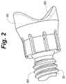
- FIG. 2is a side perspective view of a bone engagement member of a bone positioning guide in accordance with an embodiment of the invention.
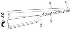
- FIG. 3Ais a side perspective view of a tip of a bone positioning guide in accordance with an embodiment of the invention.
- FIG. 3Bis a side view of a bone positioning guide with a straight tip in accordance with an embodiment of the invention.
- FIG. 3Cis a side view of a bone positioning guide with a nonlinear tip in accordance with an embodiment of the invention.
- FIG. 4is an end view of an actuator of a bone positioning guide in accordance with an embodiment of the invention.
- FIG. 5is a top plan view of a bone preparing guide in accordance with an embodiment of the invention.
- FIG. 6Ais a perspective view of a bone preparing guide, a spacer, and a tissue removing instrument location check member in accordance with an embodiment of the invention.
- FIG. 6Bis a perspective view of another embodiment of a tissue removing instrument check location member engaged with a bone preparing guide.
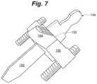
- FIG. 7is a perspective view of a bone preparing guide engaged with a spacer in accordance with an embodiment of the invention.
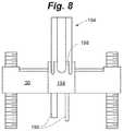
- FIG. 8is a perspective view of a bone preparing guide engaged with a tissue removal instrument location check member in accordance with an embodiment of the invention.
- FIG. 9Ais a front view of a bone positioning guide on a deformed foot in accordance with an embodiment of the invention.
- FIG. 9Bis a front view of a bone positioning guide on a foot with a corrected alignment in accordance with an embodiment of the invention.
- FIG. 10Ais a top view of a bone positioning guide on a deformed foot in accordance with an embodiment of the invention.
- FIG. 10Bis a top view of a bone positioning guide on a foot with a corrected alignment in accordance with an embodiment of the invention.
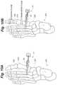
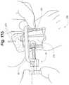
- FIGS. 11A-Cdepict a sequence of a bone positioning operation using a bone positioning guide on a foot at first, second, and third positions in accordance with an embodiment of the invention.
- FIG. 12Ais a front view of a foot with a normal first metatarsal position.
- FIG. 12Bis a front view of a foot with an isolated first metatarsal rotation bunion deformity.
- FIG. 13Ais a top view of a foot with a normal first metatarsal position.
- FIG. 13Bis a top view of a foot with an isolated first metatarsal transverse plane bunion deformity.
- FIG. 14Ais a side view of a foot with a normal first metatarsal position.
- FIG. 14Bis a side view of a foot with an isolated first metatarsal sagittal plane bunion deformity.
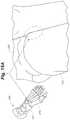
- FIG. 15Ais a perspective view and an enlarged view of a foot.
- FIG. 15Bis a perspective view of a first metatarsal.
- FIG. 16is a side perspective view of a foot depicting a bone preparation instrument inserted into a joint.
- FIG. 17is a perspective view of a foot depicting a bone positioning guide on the foot prior to an alignment of a first metatarsal.
- FIG. 18is a perspective view of a foot depicting a bone positioning guide on the foot after an alignment of a first metatarsal.
- FIG. 19is a perspective view of a foot depicting a bone positioning guide on the foot after an alignment of a first metatarsal and an insertion of a spacer into a joint space.
- FIG. 20is a perspective view of a foot depicting a bone positioning guide on the foot after an alignment of a first metatarsal and a positioning of a bone preparation guide.
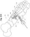
- FIG. 21Ais a perspective view of a foot depicting a bone positioning guide on the foot after an alignment of a first metatarsal and a positioning of a bone preparation guide with pins.
- FIG. 21Bis another perspective view of a foot depicting a bone positioning guide on the foot after an alignment of a first metatarsal and a positioning of a bone preparation guide with pins.
- FIG. 22is a perspective view of a foot depicting a bone preparation instrument preparing a bone of the foot guided by a guide surface of a bone preparation guide.
- FIG. 23is a perspective view of a foot depicting a bone positioning guide on the foot and a removal of a bone preparation guide.
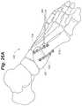
- FIG. 24is a perspective view of a foot depicting a bone positioning guide on the foot and pins.
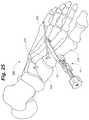
- FIG. 25is a perspective view of a foot depicting a bone positioning guide on the foot and a compression pin.
- FIG. 26Ais a side perspective view of a foot depicting bone plates across a joint between first and second bones and a compression pin in accordance with an embodiment of the invention.
- FIG. 26Bis a side perspective view of a foot depicting bone plates across a joint between first and second bones and a compression pin in accordance with an embodiment of the invention.
- FIG. 27is a side perspective view of a foot depicting bone plates across a joint between first and second bones in accordance with an embodiment of the invention.
- FIG. 28A and FIG. 28Bdepict examples of anatomically misaligned metatarsals and metatarsals that have been anatomically aligned using methods and/or instruments in accordance with the invention.
- FIG. 29A and FIG. 29Bdepict examples of anatomically misaligned metatarsals and metatarsals that have been anatomically aligned using methods and/or instruments in accordance with the invention.
- FIG. 30Aillustrates a portion of a foot having a bunion caused by a misaligned first metatarsal relative to a second metatarsal.
- FIG. 30Bshows an example base compression that can be caused after the foot of FIG. 30A is anatomically aligned.
- FIG. 31illustrates an example bone positioning operation in which a fulcrum is positioned at an intersection between a first bone and a second bone.
- FIG. 32is a perspective view of one example fulcrum.
- FIG. 33illustrates an example system of different sized fulcrums.
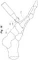
- FIG. 34is a perspective view of another bone positioning guide according to an embodiment of the invention.
- FIG. 35illustrates an example configuration of a joint spacer that can allow a bone preparation guide to rotate around the spacer.
- FIG. 36Ais a perspective view of an example configuration of a bone positioning guide having an opening with circular cross-sectional shape.
- FIG. 36Bis a perspective view of the example bone positioning guide of FIG. 36A shown with the joint spacer from FIG. 35 inserted into the guide.
- Embodiments of the inventioninclude a bone positioning guide and method of positioning bones in a medical procedure.
- the bone positioning guidecan be useful during a surgical procedure, such as a bone alignment, osteotomy, fusion procedure, and/or other procedures where one or more bones are to be prepared (e.g., cartilage or bone removal and/or cut).
- a surgical proceduresuch as a bone alignment, osteotomy, fusion procedure, and/or other procedures where one or more bones are to be prepared (e.g., cartilage or bone removal and/or cut).
- Such a procedurecan be performed, for example, on bones (e.g., adjacent bones separated by a joint or different portions of a single bone) in the foot or hand, where bones are relatively smaller compared to bones in other parts of the human anatomy.
- a procedure utilizing an embodiment of the bone positioning guidecan be performed to correct an alignment between a metatarsal (e.g., a first metatarsal) and a second metatarsal and/or a cuneiform (e.g., a medial, or first, cuneiform), such as in a bunion correction surgery.
- a metatarsale.g., a first metatarsal
- a second metatarsal and/or a cuneiforme.g., a medial, or first, cuneiform
- a procedurecan be performed by modifying an alignment of a metatarsal (e.g., a first metatarsal).
- a basilar metatarsal osteotomy proceduree.g., a basilar metatarsal osteotomy procedure.
- FIG. 1shows a side perspective view of a bone positioning guide 10 in accordance with an embodiment of the invention.
- the bone positioning guide 10can be useful for positioning a bone (e.g., orientating and/or translating) during a medical procedure.
- the bone positioning guideincludes a bone engagement member, a tip, a mechanism to urge the bone engagement member and the tip towards each other (e.g. moving the bone engagement member towards the tip, moving the tip towards the bone engagement member, or moving both simultaneously), and an actuator to actuate the mechanism.
- the mechanismWhen the mechanism is actuated it causes a first bone engaged with the bone engagement member to move to correct an alignment in more than one plane with respect to a second bone in contact with the tip.
- the correction in more than one planeincludes a correction about an axis in a frontal plane.
- bone positioning guide 10includes a main body member 20 and a shaft 30 , and the bone engagement member 40 is connected to the shaft and the tip 50 is connected to the main body member.
- the main body member 20can be sized and shaped to clear anatomy or other instrumentation (e.g., pins and guides) while positioned on a patient.
- the main body member 20includes a generally C-shaped configuration with a first end 60 and a second end 70 .
- the main bodyis sized and configured to engage bones of a human foot.
- bone positioning guide 10is illustrated as being formed of two components, main body member 20 and shaft 30 , the guide can be fabricated from more components (e.g., 3, 4, or more) that are joined together to form the guide.
- a shaft 30can be movably connected to the main body member 20 proximate its first end 60 .
- the shaft 30includes threads 80 that engage with the main body member 20 such that rotation of the shaft translates the shaft with respect to the main body member.
- the shaftcan slide within the main body member and can be secured thereto at a desired location with a set screw.
- the shaftcan be moved with respect to the main body by a ratchet mechanism. In the embodiment shown, the shaft moves along an axis that intersects the tip 50 . In other embodiments, such as that described with respect to FIG. 34 , the shaft 30 and/or bone engagement member 40 is offset from tip 50 .
- the bone positioning devicecan have a bone engagement member 40 .
- the bone engagement memberincludes a surface 90 configured to contact a bone, such as a metatarsal or a cuneiform.
- the surface 90is concave.
- Such a surfaceis adapted to promote surface contact with a generally cylindrical bone, such as a metatarsal.
- Other embodiments of surface shapesinclude planar surfaces and V-shaped surfaces.
- the bottom of the concavity or groovecan be centered between upwardly extending sidewalls configured to receive a bone.
- Each sidewallcan extend upwardly to the same height and/or at the same slope.
- one sidewallcan have a different configuration than the opposing sidewall.
- one of the sidewallsmay extend upwardly from the bottom of the concavity or groove to a lower height than the opposing sidewall.
- one sidewallmay extend upwardly at a different angle than the opposing sidewall.
- the asymmetrical configurationcan be useful for applying a force that is biased laterally instead of only being linear toward tip 50 .
- bone engagement member 40includes a pin or a clamp. Independent of whether bone engagement member 40 includes such pin or clamp, the bone engagement member can engage an anatomical feature of a bone, such as a ridge (e.g., a medial ridge of a first metatarsal). In such embodiments, the engagement generally prohibits rotational movement of the bone with respect to the bone engagement member. In other embodiments, bone may be allowed to rotate with respect to the bone engagement member.
- the bone engagement member 40is provided on an end of the shaft 30 .
- the bone engagement member 40can be rotatably coupled to the shaft 30 .
- the bone engagement member 40may or may not rotate with respect to the main body member even as it translates with respect to the main body member along with the shaft 30 and rotates with respect to the shaft.
- the bone engagement membermay oscillate about the shaft 30 , but generally does not rotate with respect to bone after contact with the bone.
- FIGS. 3A-Cdepict a tip 50 of bone positioning guide 10 , which can be at a second end 70 of the main body member opposite the first end.
- the tip 50can be useful for contacting a bone, generally a bone distinct from a bone contacting the bone engagement member.
- the tipcan be in contact with a metatarsal other than the first metatarsal (e.g., the second, third, fourth, or fifth metatarsal).
- the tipis tapered to facilitate percutaneous insertion and contact with bone.
- the tipcan also include a textured surface 100 , such as serrated, roughened, cross-hatched, knurled, etc., to reduce slippage between the tip and bone.
- the tipfurther includes a stop 110 to limit a depth of insertion.
- the shape of the tipcan be configured to stably contact bone.
- FIG. 3Bshows a side view of the bone positioning guide with a generally straight tip 50
- FIG. 3Cshows a side view of the bone positioning guide with a nonlinear tip 50 (e.g., a tip that is angled or curved).
- the tipis configured to restrict translational movement between it and a bone, but to allow rotational movement between it and the bone.
- bone positioning guide 10can also include an actuator (e.g., a knob or a handle) 120 to actuate the mechanism, in this embodiment associated with the shaft.
- the actuatorcan be useful for allowing a user to rotate the shaft with respect to the main body member 20 .
- the actuator, shaft, and bone engagement membermay include a cannulation 130 to allow the placement of a fixation wire (e.g., K-wire) through these components and into contact with or through a bone engaged with the bone engagement member.
- the fixation wirecan be placed into the bone engaged with bone engagement member 40 to fix the position of the bone engagement member with respect to the bone.
- the fixation wirecan be placed through the bone in contact with the bone engagement member and into an adjacent bone to maintain a bone position of the bone in contact with the bone engagement member and the adjacent bone.
- the mechanism to urge the bone engagement member and the tip towards each othercan include a tenaculum or tong structure.
- the guidecan include a first shaft pivotably connected to a second shaft.
- a first end of each shaftcan include an actuator, such as a handle.
- a second end of the first shaftcan include a bone engagement member, as described above.
- a second end of the second shaftcan include a tip, as described above.
- the actuatorcan be actuated (e.g., squeezed together) to move the bone engagement member and the tip closer together to position bone.
- Other embodiments of this typemay include another set of shafts and another pivoting connection such that the bone engagement member and tip translate towards each other when the actuator is actuated.
- the mechanism to urge the bone engagement member and the tip towards each othercan include a rack and pinion structure.
- the rackcan include a tip, as described above.
- the pinioncan include a bone engagement member, as described above, and an actuator (e.g., a knob).
- the actuatorcan be actuated (e.g., turned about an axis generally perpendicular to a direction of travel) to move the bone engagement member and the tip closer together to position bone.
- Embodiments of the bone positioning guidemay include any suitable materials.
- the bone positioning guideis fabricated from a radiolucent material such that it is relatively penetrable by X-rays and other forms of radiation, such as thermoplastics and carbon-fiber materials. Such materials are useful for not obstructing visualization of bones using an imaging device when the bone positioning guide is positioned on bones.
- Embodiments of the bone positioning guidecan be useful in operation for temporarily positioning a bone or bones during a medical procedure.
- Bone positioningcan be useful, for instance, to correct an anatomical misalignment of bones and temporarily maintain an anatomically aligned position, such as in a bone alignment and/or fusion procedure.
- the bone positioning guideis capable of reducing an angle between the first metatarsal and the second metatarsal from over 10 degrees (e.g., up to about 35 degrees) to about 10 degrees or less (e.g., to about 1-5 degrees), including to negative angles of about ⁇ 5 degrees.
- the bone positioning guideis also capable of rotating the first metatarsal about its long axis with respect to the medial cuneiform from a rotational angle of over 4 degrees to a rotational angle of less than 4 degrees (e.g., to about 0 to 2 degrees).
- a bone preparation guidemay be provided to facilitate the preparation of a bone.
- the bone preparation guidecan be provided with a bone positioning guide, or either device can be provided or used independently.
- An example of a bone preparation guide 150is shown in FIG. 5 .
- the bone preparation guide 150includes a body 154 defining a first guide surface 160 to define a first preparing plane and a second guide surface 164 to define a second preparing plane.
- a tissue removing instrumente.g., a saw, rotary bur, osteotome, etc., not shown
- can be aligned with the surfaces to remove tissuee.g., remove cartilage or bone and/or make cuts to bone).
- the first and second guide surfaces 160 , 164can be spaced from each other by a distance, (e.g., between about 2 millimeters and about 10 millimeters, such as between about 4 and about 7 millimeters). In the embodiment shown, the first and second guide surfaces are parallel, such that cuts to adjacent bones using the guide surfaces will be generally parallel.
- a first facing surface 166is positioned adjacent the first guide surface 160 and/or a second facing surface 168 is positioned adjacent the second guide surface 164 .
- the distance between the first guide surface and the first facing surfacedefines a first guide slot
- the distance between the second guide surface and the second facing surfacedefines a second guide slot.
- Each slotcan be sized to receive a tissue removing instrument to prepare the bone ends.
- the first and second slotsmay be parallel or skewed.
- the facing surfaceseach contain a gap, such that the surface is not a single, continuous surface. In other embodiments, the facing surfaces can be a single, continuous surface lacking any such gap.
- An opening 170can be defined by the body 154 between the first and second guide surfaces.
- the openingcan be an area between the guide surfaces useful for allowing a practitioner to have a visual path to bones during bone preparation and/or to receive instruments.
- the openingextends across the body and a distance from a surface 172 opposite of the first facing surface 166 to a surface 174 opposite of the second facing surface 168 .
- the embodiment shownalso includes a first end 176 extending from the body 154 in a first direction and a second end 178 extending from the body in a second direction.
- the second directioncan be different than the first direction (e.g., an opposite direction).
- each of the first end and the second endcan include at least one fixation aperture 180 configured to receive a fixation pin (not shown in FIG. 5 ) to secure the guide to a bone.
- such aperturesmay extend through the end at a vertical or skewed angle relative to a top surface of the guide.
- the bone preparation guide 150can also include a first adjustable stabilization member 182 engaged with the first end 176 .
- the bone preparation guidecan include a second adjustable stabilization member 184 engaged with the second end 178 .
- Each of the memberscan be threaded and engage a threaded aperture defined by the ends. The elevation of each end can be adjusted with respect to a bone by adjusting the stabilization member.
- the stabilization membersare cannulated such that they can receive a fixation pin.
- the bone preparation guidecan also include a spacer 188 extending downward from the body 154 and configured to be placed into a joint.
- the spacer 188is selectively engageable with the body.
- the spacercan have a first portion 190 configured to extend into a joint space and a second portion 192 engageable with the body 154 .
- the spacercan be received within opening 170 , such that the spacer extends from the body in between the first and second guide surfaces.
- Such a spacercan be useful for positioning the body at a desired position with respect to a joint and for properly positioning the guide with respect to bones to be cut in more than one plane (e.g., three planes selected from more than one of a frontal plane, a transverse plane, and a sagittal plane).
- the distance between the spacer and the first guide surfacecan define a length of tissue removal (e.g., bone or cartilage to be cut) from a first bone
- the distance between the spacer and the second guide surfacecan define a length of tissue removal (e.g., bone or cartilage to be cut) from a second bone.
- the bone preparation guidecan also include a tissue removal location check member 194 engageable with the body 154 and configured to extend to a first bone and a second bone.
- the tissue removal location check membercan have a first portion 196 configured to extend into contact with first and second bones and a second portion 198 engageable with the body.
- the tissue removal location check memberextends from the body at both the first and second guiding surfaces.
- separate tissue removal location check membersare provided for independent insertion into respective slots of the guide. Accordingly, embodiments of tissue removal location check members are useful for allowing a practitioner to see where a tissue removing instrument guided by the surfaces will contact the bone to be prepared.
- Embodiments of the bone preparation guidecan be useful in operation for guiding a preparation of a bone or bones at a targeted anatomy.
- Bone preparationcan be useful, for instance, to facilitate contact between leading edges of adjacent bones, separated by a joint, or different portions of a single bone, separated by a fracture, such as in a bone alignment and/or fusion procedure.
- Embodiments of the present inventionalso include methods for temporarily fixing an orientation of a bone or bones, for example, prior to or in conjunction with permanently fixing the orientation of the bone or bones.
- the method of positioning a boneincludes the steps of moving a bone from an anatomically misaligned position to an anatomically aligned position with respect to another bone and preparing an end of the moved bone and a facing end of another bone.
- the end of at least one of the moved bone and the other boneis prepared after moving the bone into the aligned position.
- the boneis anatomically aligned in more than one plane with respect to another bone by applying a force to one bone at a single location, such that the bone both translates and rotates in response to the force.
- the moving stepcan be accomplished with a bone positioning device and/or the preparing step can be accomplished with a bone preparation guide, as described herein.
- FIGS. 9A-Bdepict frontal views of a bone positioning guide 10 on a foot 200 having a first metatarsal 210 , a medial cuneiform 220 , a second metatarsal 292 , and a third metatarsal 294 .
- FIG. 9Adepicts a foot 200 with an uncorrected bunion deformity
- FIG. 9Bdepicts the foot 200 with an alignment corrected by the bone positioning guide 10 .
- Solid line L 1represents the starting location of the bone positioning guide 10 and dotted line L 2 represents the finishing location of the bone positioning guide.
- FIG. 10Ashows a top view of a foot 200 with an uncorrected bunion deformity
- FIG. 10Bshows a top view of the foot 200 with an alignment corrected by the bone positioning guide 10 , emphasizing the rotational correction in the frontal plane and the lateral correction in the transverse plane.
- FIGS. 11A-Cshow three sequential images of a bone positioning guide 10 on a foot 200 positioning a first metatarsal 210 with respect to a second metatarsal 292 .
- FIG. 11Arepresents the beginning of the procedure
- FIG. 11Bthe middle
- FIG. 11Cthe end.
- the orientation of the pins 270is useful for visualizing the amount of rotation of the first metatarsal 210 in each image.
- FIGS. 11A-Cit can be seen the bone positioning guide 10 and the first metatarsal 210 are rotating in the frontal plane in response to actuation of bone positioning guide 10 . Further, the angle between the first metatarsal 210 and second metatarsal 292 is reduced, as the space that can be seen between the first and second metatarsals in FIG. 11A is eliminated in FIG. 11C .
- FIGS. 12A and 12Bshow frontal plane views of a foot 200 .
- the foot 200is normal, while in FIG. 12B the foot is depicted with an uncorrected bunion deformity showing an isolated axial rotation of the first metatarsal 210 .
- Solid line L 3indicates the alignment of the first metatarsal 210 relative to ground, while dotted line L 4 in FIG. 12B indicates the extent of axial rotation in the frontal plane.
- FIGS. 13A and 13Bshow transverse plane views of a foot 200 .
- the foot 200is normal, while in FIG. 13B the foot is depicted with an uncorrected bunion deformity showing an isolated transverse plane first metatarsal 210 deviation.
- Solid line L 5indicates the alignment of the second metatarsal 292 and solid line L 6 indicates the proper alignment of the first metatarsal 210 relative to the second metatarsal 292 . The angle between these two lines forms the intermetatarsal angle (IMA).
- Dotted line L 7 in FIG. 13Bindicates the extent of transverse deviation.
- FIGS. 14A and 14Bshow sagittal plane views of a foot 200 .
- the foot 200is normal, while in FIG. 14B the foot is depicted with an uncorrected bunion deformity showing an isolated sagittal deviation of the first metatarsal 210 .
- Solid line L 8indicates the proper alignment of the first metatarsal 210
- dotted line L 9 in FIG. 14Bindicates the extent of sagittal deviation.
- a specific embodiment of a method in accordance with an embodiment of the inventionincludes the steps of engaging a bone engagement member with a first bone, placing a tip of the bone positioning guide in apposition to a second bone, the second bone being different from the first bone, and moving the bone engagement member with respect to the tip to change the position of the first bone with respect to the second bone in more than one plane.
- at least one of an end of the first bone and a facing end of a third boneare prepared (e.g., only the end of the first bone or both the end of the first bone and the end of the second bone), optionally using a preparation guide.
- the methodincludes the step of mobilizing a joint for a corrective procedure. For example, after creating surgical access to the joint and before moving the bones into an aligned position, tissue can be released to allow a bone, such as a metatarsal, to rotate freely.
- obstructing bonemay be excised (e.g., a dorsolateral flare of the metatarsal base, a plantar flare of the metatarsal base (sometimes referred to as a plantar condyle), part of an end of a metatarsal facing a cuneiform, or osteophyte) to further promote free rotation by creating relatively flat surfaces with respect to a frontal plane.
- FIG. 15AAn example of a dorsolateral flare F on a first metatarsal 210 of a foot 200 is shown in FIG. 15A .
- FIG. 15BAn example of a plantar flare PF on a first metatarsal 210 is shown in FIG. 15B .
- FIG. 15Balso depicts a medial ridge MR, which, in some embodiments, can be engaged by the bone engaging member of a bone positioning guide.
- Embodiments of methods in accordance with the inventioncan also include steps performed after preparing the ends of the bones.
- the ends of the bonesmay be placed in apposition and optionally compressed together and the position of the bones can be fixed with one or more bone fixation devices (e.g., compressing bone screw, bone plate, bone staple, external fixator, intramedullary implant or nail) prior to a closing of the surgical access to the joint.
- bone fixation devicese.g., compressing bone screw, bone plate, bone staple, external fixator, intramedullary implant or nail
- FIGS. 16-27depicting a foot 200 having a first metatarsal 210 , a medial cuneiform 220 , and a second metatarsal 292 . Note, unless otherwise indicated, the steps described need not be carried out in the order described.
- a bone preparation instrument 296can be inserted into the joint (e.g., first tarsal-metatarsal joint) to release soft tissues and/or excise the plantar flare from the base of the first metatarsal 210 , as shown in FIG. 16 .
- Excising the plantar flaremay involve cutting plantar flare off the first metatarsal 210 so the face of the first metatarsal is generally planar. This step helps to mobilize the joint to facilitate a deformity correction.
- the dorsal-lateral flare of the first metatarsalmay also be excised to create space for the deformity correction (e.g., with respect to rotation of the first metatarsal).
- a portion of the metatarsal base facing the medial cuneiformcan be removed during this mobilizing step.
- a tip 50 of a bone positioning guide 10can be inserted on the lateral side of a metatarsal other than the first metatarsal 210 , such as the second metatarsal 292 .
- the tipcan be positioned proximally at a base of the second metatarsal 292 and a third metatarsal 294 interface.
- a surface of a bone engagement member 40can be placed on the proximal portion of the first metatarsal 210 .
- the bone engagement memberengages a medial ridge of the first metatarsal 210 .
- the body 20 of the positioning guidecan be generally perpendicular to the long axis of the second metatarsal 292 .
- the actuator 120can be actuated to extend the shaft 30 to reduce the angle (transverse plane angle between the first metatarsal and the second metatarsal) and rotate the first metatarsal about its axis (frontal plane axial rotation).
- the first metatarsal 210can be properly positioned with respect to the medial cuneiform 220 by moving the bone engagement member 40 with respect to the tip 50 . In some embodiments, such movement simultaneously pivots the first metatarsal with respect to the cuneiform and rotates the first metatarsal about its longitudinal axis into an anatomically correct position to correct a transverse plane deformity and a frontal plane deformity.
- body 20rotates in a generally lateral direction during this step.
- fixation pins(not shown in FIG. 18 ) can be inserted into the bones prior to the positioning step (e.g., freehand or using apertures in the guide as a template), and can be used to impart additional force (transverse, sagittal, and/or frontal plane rotational) to the first metatarsal 210 , if desired.
- the bone positioning guide 10can hold the desired position of the first metatarsal 210 with respect to the second metatarsal 292 .
- a fixation wire 298can be inserted through a cannulation in the shaft 30 and driven into the first metatarsal 210 and the second metatarsal 292 to hold the corrected position.
- a joint spacer 188can be positioned within the joint between the first metatarsal and the medial cuneiform.
- a bone preparation guide 150can be placed over the joint spacer 188 and engaged with the joint spacer to set a position and orientation of the bone preparation guide relative to the joint.
- the bone preparation guide 150can be positioned proximal to the bone positioning guide 10 in longitudinal alignment with the long axis of the first metatarsal 210 and the medial cuneiform 220 , generally on the dorsal or dorsal-medial surface.
- the spacer 188is positioned after the guide 150 is provisionally placed on the bones.
- bone preparation guide 150 and joint spacer 188are placed simultaneously.
- bone preparation guide 150is placed on the bones without using joint spacer 188 to aid with positioning.
- one or more fixation pins 270can be inserted into apertures of the bone preparation guide 150 to secure the guide to the first metatarsal 210 and the medial cuneiform 220 .
- some pins 270can be inserted at an angle or in a converging orientation to help prevent movement of the bone preparation guide 150 during a tissue removing step.
- two of the pins 270are parallel to allow the bone preparation guide 150 to be removed from the foot without removing all the pins.
- the spacer 188can optionally be removed in embodiments having a selectively engageable spacer (e.g., a joint spacer 188 that is physically removable from bone preparation guide 150 ).
- the location of the intersection of the tissue removing instrument and the bone to be preparedis confirmed before bone preparation.
- a tissue removing instrument location check membercan be engaged with the preparation guide to visually confirm where a tissue removal instrument will contact the bone.
- a tissue removal instrumentis engaged with the preparation guide to visually confirm where the instrument will contact the bone.
- visual confirmationcan include the use of an imaging device, such as an X-ray. If the position of the preparation guide is correct, additional fixation pins may be inserted through the apertures (e.g., angled apertures) to further fix the position of the preparation guide with respect to the first metatarsal and the medial cuneiform. In some embodiments, the spacer is reattached prior to further bone preparation steps.
- the end of the first metatarsal 210 facing the medial cuneiform 220can be prepared with a tissue removing instrument 296 guided by a guide surface of bone preparation guide 150 (e.g., inserted through a slot defined by a first guide surface and a first facing surface).
- the first metatarsal 210 end preparationis done after the alignment of the bones, e.g., by actuating bone positioning guide 10 before preparing the end of first metatarsal 210 .
- the first metatarsal 210 end preparationis done before the alignment of the bones, e.g., by preparing the end of the first metatarsal 210 before actuating bone positioning guide 10 .
- the end of the medial cuneiform 220 facing the first metatarsal 210can be prepared with the tissue removing instrument 296 guided by a guide surface of bone preparation guide 150 (e.g., inserted through a slot defined by a second guide surface and a second facing surface).
- the medial cuneiform 220 end preparationis done after the alignment of the bones.
- the medial cuneiform 220 end preparationis done before the alignment of the bones.
- the cuneiform cut and the metatarsal cutcan be parallel, conforming cuts. In the specific embodiment shown in FIG.
- a saw bladecan be inserted through a first slot to cut a portion of the medial cuneiform and the saw blade can be inserted through a second slot to cut a portion of the first metatarsal (e.g., in some embodiments the medial cuneiform can be cut before the first metatarsal). Accordingly, in the embodiment shown, the cuts to both the first metatarsal and the medial cuneiform were preformed after the first metatarsal was positioned.
- any angled/converging pinscan be removed and the bone preparation guide 150 can be lifted off the parallel pins 270 , as shown in FIG. 23 .
- the parallel pinscan be referred to as “reference pins” which can serve as a reference in later steps to ensure that the corrected alignment of the first metatarsal 210 has been maintained.
- the joint spacercan also be removed before, after, or simultaneously with the bone preparation guide. In some embodiments, the bone positioning guide 10 is also removed from the foot.
- the tissue (e.g., bone or cartilage slices) from the first metatarsal and the medial cuneiformcan be removed from the joint site and the joint surfaces can be fenestrated, if desired. If the bone positioning guide was taken off the foot, it can be put back on, as shown in FIG. 24 , before the additional steps discussed below.
- tissuee.g., bone or cartilage slices
- the ends of the two bonescan be placed in apposition and optionally compressed together by provisionally fixating the joint.
- the two bonesmay be placed in apposition by placing the cut end of the first metatarsal 210 in abutment with the cut end of the medial cuneiform 220 .
- the cut end of the first metatarsal 210is placed adjacent to, and optionally in contact with, the cut end of the medial cuneiform 220 .
- a compression pinsuch as a threaded olive pin 300 can be inserted through the first metatarsal 210 and into the medial cuneiform 220 to provide compression and provisional fixation between the first metatarsal and the medial cuneiform. Additional compression pins can be inserted to provide additional stability. As shown, the parallel reference pins should be aligned during this step. In some embodiments, a practitioner checks for alignment of the parallel reference pins prior to insertion of the compression pin, and, if they are not aligned, adjusts the position of the first metatarsal until desired alignment is achieved.
- FIG. 26Ashows a first bone plate 310 positioned on a dorsal-medial side of the first metatarsal and medial cuneiform and a second bone plate 320 positioned on a medial-plantar side of the first metatarsal and the medial cuneiform.
- a bone fixation devicee.g., two bone plates positioned in different planes, as shown
- the second bone plate 320can be a helical bone plate positioned from a medial side of the cuneiform to a plantar side of the first metatarsal across the joint space.
- the platescan be applied with the insertion of bone screws.
- the compression pincan be removed and the incision can be closed.
- FIGS. 28A /B and 29 A/Binclude examples of anatomically misaligned metatarsals and metatarsals that have been anatomically aligned using methods and/or instruments in accordance with the invention.
- FIG. 28Ashows a left foot pre-operation and post-operation
- FIG. 28Bshows a right foot pre-operation and post-operation.
- IMAintermetatarsal angle
- FIGS. 29A and 29Bshow the correction of an axial rotation in a frontal rotational plane.
- FIG. 29Ashows a pre-operative image and a post-operative image of a right foot.
- FIG. 29Bshows pre-operative views of a left foot 200 and a right foot 200 . Again, by comparing the location of the sesamoid bones 400 with respect to a reference location, such as ground, the planter surface of the foot, and/or a cuneiform, it can be seen this patient's metatarsal is rotated out of alignment.
- Bone positioningcan be useful, for instance, to correct an anatomical misalignment of bones and temporarily maintain an anatomically aligned position, such as in a bone alignment and/or fusion procedure.
- an “anatomically aligned position”means that an angle of a long axis of a first metatarsal relative to a long axis of a second metatarsal is about 10 degrees or less in the transverse plane or sagittal plane.
- anatomical misalignmentcan be corrected in both the transverse plane and the frontal plane.
- a normal intermetatarsal angle (“IMA”) between a first metatarsal and a second metatarsalis less than about 9 degrees.
- An IMA of between about 9 degrees and about 13 degreesis considered a mild misalignment of the first metatarsal and the second metatarsal.
- An IMA of greater than about 16 degreesis considered a severe misalignment of the first metatarsal and the second metatarsal.
- methods in accordance with the inventionare capable of anatomically aligning the bone(s) by reducing the IMA from over 10 degrees to about 10 degrees or less (e.g., to an IMA of about 1-5 degrees), including to negative angles of about ⁇ 5 degrees or until interference with the second metatarsal, by positioning the first metatarsal at a different angle with respect to the second metatarsal.
- a normal first metatarsalWith respect to the frontal plane, a normal first metatarsal will be positioned such that its crista prominence is generally perpendicular to the ground and/or its sesamoid bones are generally parallel to the ground and positioned under the metatarsal. This position can be defined as a metatarsal rotation of 0 degrees. In a misaligned first metatarsal, the metatarsal is axially rotated between about 4 degrees to about 30 degrees or more. In some embodiments, methods in accordance with the invention are capable of anatomically aligning the metatarsal by reducing the metatarsal rotation from about 4 degrees or more to less than 4 degrees (e.g., to about 0 to 2 degrees) by rotating the metatarsal with respect to the medial cuneiform.
- bone positioning and preparing guide systems and methodshave been described, is should be appreciated that the concepts of the disclosure can be altered in practice, e.g., based on the needs of the clinician, the patient undergoing the bone repositioning procedure, the specific anatomy being treated, and/or the target clinical outcome.
- the described systems and techniquesmay be modified to utilize a fulcrum about which rotation and/or pivoting of one bone relative to another bone occurs via bone positioning guide 10 .
- the fulcrumcan establish and/or maintain space between adjacent bones being compressed between bone engagement member 40 and tip 50 of bone positioning guide 10 , preventing lateral translation or base shift of the bones during rotation and pivoting.
- FIG. 30Aillustrates a portion of a foot having a bunion caused by a misaligned first metatarsal 210 relative to second metatarsal 292 .
- FIG. 30Bshows the foot of FIG. 30A after being anatomically aligned to correct the misalignment using bone positioning guide 10 .
- first metatarsal 210has been rotated counterclockwise in the frontal plane (from the perspective of a patient, clockwise from the perspective of a frontal observer) and also pivoted in the transverse plane (e.g., such that the angle 350 between the first metatarsal 210 and second metatarsal 292 is reduced).
- Rotation and pivoting of first metatarsal 210can cause the base 352 of first metatarsal 210 to shift relative to medial cuneiform 220 .
- the offset 354 A between first metatarsal 210 and medial cuneiform 220be reduced to zero (e.g., such that there is substantially no offset) after rotation and pivoting.
- the base 352 of first metatarsal 210abutting medial cuneiform 220 has shifted toward second metatarsal 292 .
- a cliniciancan insert a fulcrum in the notch between first metatarsal 210 and second metatarsal 292 at the base of the metatarsals (e.g., adjacent respective cuneiform) before actuating bone positioning guide 10 .
- the fulcrumcan provide a point about which first metatarsal 210 can rotate and/or pivot while helping minimize or avoid base compression between the first metatarsal and the second metatarsal.
- first metatarsal 210 and medial cuneiform 220may be better angled relative to the guide slots of bone preparation guide 150 (once installed), providing a better cut angle through the guide slots then without use of the fulcrum. This can help reduce or eliminate unwanted spring-back, or return positioning, of first metatarsal 210 after removing bone positioning guide 10 .
- FIG. 31illustrates a bone positioning operation in which a fulcrum 356 is positioned at an intersection between a first bone and a second bone, where the first bone is being realigned relative to the second bone.
- FIG. 31illustrates fulcrum 356 being positioned between first metatarsal 210 and second metatarsal 292 .
- Fulcrum 356may be positioned distally of bone preparation guide 150 between first metatarsal 210 and second metatarsal 292 as shown in FIG. 31 or, in other applications, proximally of the guide (e.g., at the ends of the first and second metatarsals abutting the medial and intermediate cuneiform bones, respectively).
- the cliniciancan insert fulcrum 356 between first metatarsal 210 and second metatarsal 292 (or other adjacent bones, when not performing a metatarsal realignment) at any time prior to actuating bone positioning guide 10 .
- fulcrum 356can be inserted between first metatarsal 210 and second metatarsal 292 before or after inserting joint spacer 188 and/or placing bone preparation guide 150 over the joint being operated upon.
- the clinicianprepares the joint being operated upon to release soft tissues and/or excise the plantar flare from the base of the first metatarsal 210 , as discussed above.
- the clinicianinserts fulcrum 356 at the joint between the first metatarsal and the second metatarsal.
- the cliniciancan subsequently actuate bone positioning guide 10 (e.g., rotate knob 120 ).
- actuation of bone positioning guide 10causes the first metatarsal 210 to rotate counterclockwise in the frontal plane (from the perspective of a patient) and also pivot in the transverse plane about the fulcrum.
- actuationcauses the first metatarsal to rotate clockwise in the frontal plane (from the perspective of a patient) and also pivot in the transverse plane about the fulcrum.
- actuation of bone positioning guide 10can supinate the first metatarsal in the frontal plane and pivot the first metatarsal in the transverse plane about fulcrum 356 .
- fulcrum 356can minimize or eliminate base compression between adjacent bones being operated upon, in other embodiments as discussed above, the described systems and techniques can be implemented without using the fulcrum.
- FIG. 32is a perspective view of one example instrument that can be used as fulcrum 356 .
- fulcrum 356has a generally rectangular shape and tapers in thickness along at least a portion of the length from the trailing end 358 to the leading end 360 .
- Fulcrum 356may be sized sufficiently small so that it does not interfere with placement of bone preparation guide 150 on the joint being worked upon.
- the clinicianis provided a system containing multiple different size fulcrums and allowed to choose the specific sized fulcrum desired for the specific procedure being performed.
- fulcrum 356has a width ranging from 5 millimeters to 15 millimeters (e.g., about 6 millimeters to about 10 millimeters) and a thickness ranging 1 millimeter to 12 millimeters (e.g., about 2 millimeters to about 3 millimeters), although fulcrums with different dimensions can be used. While FIGS. 32 and 33 illustrate one example style of fulcrum, other mechanical instruments providing a fulcrum functionality can be used without departing from the scope of the disclosure. For instance, as alternative examples, a surgical pin or screw driver head may be used as fulcrum 356 .
- bone positioning guide 10can have a variety of different configurations, including a configuration in which bone engagement member 40 is laterally offset from tip 50 .
- FIG. 34is a perspective view of bone positioning guide 10 showing an example arrangement in which bone engagement member 40 is laterally offset from tip 50 .
- the first end 60 of main body member 20is laterally offset from an axis 362 extending through shaft 30 and a geometric center of bone engagement member 40 .
- tip 50is offset laterally in the direction of the cuneiform relative to bone engagement member 40 .
- a joint spacer 188can be positioned in a joint between a first metatarsal and a medial cuneiform before placing bone preparation guide 150 over the joint spacer.
- Bone preparation guide 150can have an opening 170 ( FIG. 5 ) sized to receive joint spacer 188 .
- opening 170 of bone preparation guide 150is size and/or shaped indexed to joint spacer 188 such that there is substantially no, or no, relative movement between the guide and spacer (once bone preparation guide 150 is placed over joint spacer 188 ). This arrangement can ensure that bone preparation guide 150 is positioned precisely at the location where guided by joint spacer 188 .
- opening 170 of bone preparation guide 150may not be sized and/or shaped and/or indexed to joint spacer 188 .
- opening 170 of bone preparation guide 150may have a different cross-sectional size and/or shape than the cross-sectional size and/or shape of joint spacer 188 .
- bone preparation guide 150may actuate or rotate about an axis extending through the length of joint spacer 188 .
- the clinicianmay rotate bone preparation guide 150 around joint spacer 188 until the guide slots of the bone preparation guide are better aligned with the ends of the bones to be cut (e.g., first metatarsal 210 and medial cuneiform 220 ).
- the guidemay rotate freely (e.g., 360 degrees) around the joint seeker or within a bounded angular range (e.g., from plus 20 degrees to minus 20 degrees from a normal position).
- FIG. 35illustrates one example configuration of a joint spacer 188 that can allow bone preparation guide 150 to rotate around the seeker.
- joint spacer 188has a proximal portion 370 having a cylindrical cross-section and a distal portion 372 having a rectangular cross-section. A leading edge of the distal portion 372 is insertable into the joint between the first metatarsal 210 and the medial cuneiform 220 .
- body 154 of the guideFIG. 5
- Thiscan allow the guide to be rotated around the proximal portion.
- opening 170 of bone preparation guide 150may be size and/or shape indexed to the cross-sectional size and/or shape of joint spacer 188 but still provide relative rotation between the two components.
- opening 170may have a circular cross-section sized and shaped to receive proximal portion 370 of joint spacer 188 from FIG. 35 . Because both opening 170 of bone preparation guide 150 and proximal portion 370 of joint spacer 188 have circular cross-sections in such an embodiment, the two components may rotate relative to each other.
- FIG. 36Ais a perspective view of an example configuration of bone preparation guide 150 having an opening 170 with circular cross-sectional shape.
- FIG. 36Bis a perspective view of the example bone preparation guide of FIG. 36A shown with joint spacer 188 from FIG. 35 inserted into the guide.
- the bone preparation guide and/or joint spacermay include a locking mechanism that is engageable to lock the rotational angle of the bone preparation guide relative to the joint spacer.
- bone preparation guide 150may include a set screw with thumb wheel that can be rotated, causing a distal end of the set screw to bear against or retract away from joint spacer 188 .
- a cliniciancan rotate bone preparation guide 150 around joint spacer 188 until the guide slots of the bone preparation guide are best aligned with the ends of the bones to be cut (e.g., first metatarsal 210 and medial cuneiform 220 ). The clinician can then engage the locking mechanism to prevent further rotation of bone preparation guide 150 relative to joint spacer 188 before performing further steps of the procedure.
- Embodiments of the inventionalso include a disposable, sterile kit that includes an embodiment of a bone positioning guide and/or preparation guide described herein.
- Other components that may be included within the sterile kitinclude bone fixation devices.
Landscapes
- Health & Medical Sciences (AREA)
- Surgery (AREA)
- Life Sciences & Earth Sciences (AREA)
- Orthopedic Medicine & Surgery (AREA)
- Biomedical Technology (AREA)
- Public Health (AREA)
- Veterinary Medicine (AREA)
- Engineering & Computer Science (AREA)
- Nuclear Medicine, Radiotherapy & Molecular Imaging (AREA)
- Heart & Thoracic Surgery (AREA)
- Medical Informatics (AREA)
- Molecular Biology (AREA)
- Animal Behavior & Ethology (AREA)
- General Health & Medical Sciences (AREA)
- Dentistry (AREA)
- Oral & Maxillofacial Surgery (AREA)
- Neurology (AREA)
- Surgical Instruments (AREA)
- Orthopedics, Nursing, And Contraception (AREA)
Abstract
Description
Claims (30)
Priority Applications (2)
| Application Number | Priority Date | Filing Date | Title |
|---|---|---|---|
| US16/731,612US10874446B2 (en) | 2015-07-14 | 2019-12-31 | Bone positioning guide |
| US16/997,864US11116558B2 (en) | 2015-07-14 | 2020-08-19 | Bone positioning guide |
Applications Claiming Priority (7)
| Application Number | Priority Date | Filing Date | Title |
|---|---|---|---|
| US201562192319P | 2015-07-14 | 2015-07-14 | |
| US201562205338P | 2015-08-14 | 2015-08-14 | |
| US14/981,335US9622805B2 (en) | 2015-08-14 | 2015-12-28 | Bone positioning and preparing guide systems and methods |
| US15/210,426US9936994B2 (en) | 2015-07-14 | 2016-07-14 | Bone positioning guide |
| US15/910,428US10335220B2 (en) | 2015-07-14 | 2018-03-02 | Bone positioning guide |
| US16/422,557US11185359B2 (en) | 2015-07-14 | 2019-05-24 | Bone positioning guide |
| US16/731,612US10874446B2 (en) | 2015-07-14 | 2019-12-31 | Bone positioning guide |
Related Parent Applications (1)
| Application Number | Title | Priority Date | Filing Date |
|---|---|---|---|
| US16/422,557ContinuationUS11185359B2 (en) | 2015-07-14 | 2019-05-24 | Bone positioning guide |
Related Child Applications (1)
| Application Number | Title | Priority Date | Filing Date |
|---|---|---|---|
| US16/997,864ContinuationUS11116558B2 (en) | 2015-07-14 | 2020-08-19 | Bone positioning guide |
Publications (2)
| Publication Number | Publication Date |
|---|---|
| US20200146738A1 US20200146738A1 (en) | 2020-05-14 |
| US10874446B2true US10874446B2 (en) | 2020-12-29 |
Family
ID=60989336
Family Applications (7)
| Application Number | Title | Priority Date | Filing Date |
|---|---|---|---|
| US16/422,557Active2036-12-15US11185359B2 (en) | 2015-07-14 | 2019-05-24 | Bone positioning guide |
| US16/731,612ActiveUS10874446B2 (en) | 2015-07-14 | 2019-12-31 | Bone positioning guide |
| US16/997,864ActiveUS11116558B2 (en) | 2015-07-14 | 2020-08-19 | Bone positioning guide |
| US17/537,183ActiveUS11602386B2 (en) | 2015-07-14 | 2021-11-29 | Bone positioning guide |
| US18/182,995ActiveUS11950819B2 (en) | 2015-07-14 | 2023-03-13 | Bone positioning guide |
| US18/627,609ActiveUS12102368B2 (en) | 2015-07-14 | 2024-04-05 | Bone positioning guide |
| US18/901,388PendingUS20250017639A1 (en) | 2015-07-14 | 2024-09-30 | Bone positioning guide |
Family Applications Before (1)
| Application Number | Title | Priority Date | Filing Date |
|---|---|---|---|
| US16/422,557Active2036-12-15US11185359B2 (en) | 2015-07-14 | 2019-05-24 | Bone positioning guide |
Family Applications After (5)
| Application Number | Title | Priority Date | Filing Date |
|---|---|---|---|
| US16/997,864ActiveUS11116558B2 (en) | 2015-07-14 | 2020-08-19 | Bone positioning guide |
| US17/537,183ActiveUS11602386B2 (en) | 2015-07-14 | 2021-11-29 | Bone positioning guide |
| US18/182,995ActiveUS11950819B2 (en) | 2015-07-14 | 2023-03-13 | Bone positioning guide |
| US18/627,609ActiveUS12102368B2 (en) | 2015-07-14 | 2024-04-05 | Bone positioning guide |
| US18/901,388PendingUS20250017639A1 (en) | 2015-07-14 | 2024-09-30 | Bone positioning guide |
Country Status (6)
| Country | Link |
|---|---|
| US (7) | US11185359B2 (en) |
| EP (2) | EP4483824A3 (en) |
| JP (3) | JP6985248B2 (en) |
| AU (3) | AU2016294588B2 (en) |
| CA (1) | CA2991424A1 (en) |
| ES (1) | ES3000069T3 (en) |
Cited By (11)
| Publication number | Priority date | Publication date | Assignee | Title |
|---|---|---|---|---|
| US11439415B2 (en) | 2020-11-18 | 2022-09-13 | Fusion Orthopedics USA, LLC | Osteotomy cutting systems and surgical techniques |
| US11547425B1 (en) | 2022-05-19 | 2023-01-10 | Gramercy Extremity Orthopedics Llc | Tarsometatarsal joint arthrodesis tools and related method for bunion correction |
| US20230027816A1 (en)* | 2021-07-22 | 2023-01-26 | Inverted Ortho, LLC | Oblique diaphyseal osteotomy system for metatarsal shortening |
| US11602386B2 (en)* | 2015-07-14 | 2023-03-14 | Treace Medical Concepts, Inc. | Bone positioning guide |
| US11672549B2 (en) | 2020-11-18 | 2023-06-13 | Fusion Orthopedics USA, LLC | Surgical jig |
| US12064127B2 (en) | 2020-11-18 | 2024-08-20 | Fusion Orthopedics USA, LLC | Surgical cutting block including multiple cut guides |
| US12232790B2 (en) | 2022-12-30 | 2025-02-25 | IvyTech Design LLC | Adjustable angle orthopedic distractor, compressor, and distractor-compressor |
| US12364528B2 (en) | 2021-06-17 | 2025-07-22 | Wright Medical Technology, Inc. | Minimally invasive surgery osteotomy fragment shifter, stabilizer, and targeter |
| US12364523B2 (en) | 2017-10-27 | 2025-07-22 | Wright Medical Technology, Inc. | Implant with intramedullary portion and offset extramedullary portion |
| US12419673B2 (en) | 2012-03-01 | 2025-09-23 | Wright Medical Technology, Inc. | Surgical staple |
| US12433606B2 (en) | 2019-05-13 | 2025-10-07 | Wright Medical Technology, Inc. | Surgical tools and methods of use |
Families Citing this family (21)
| Publication number | Priority date | Publication date | Assignee | Title |
|---|---|---|---|---|
| US10376268B2 (en) | 2015-02-19 | 2019-08-13 | First Ray, LLC | Indexed tri-planar osteotomy guide and method |
| US9622805B2 (en)* | 2015-08-14 | 2017-04-18 | Treace Medical Concepts, Inc. | Bone positioning and preparing guide systems and methods |
| WO2018151859A1 (en) | 2017-02-16 | 2018-08-23 | Paragon 28, Inc. | Implants, devices, systems, kits and methods of implanting |
| EP3720366B1 (en)* | 2017-12-06 | 2024-07-17 | Paragon 28, Inc. | Alignment guides, cut guides, systems and methods of use and assembly |
| US10646263B2 (en)* | 2018-07-11 | 2020-05-12 | Crossroads Extremity Systems, Llc | Bunion correction system and method |
| JP7481260B2 (en) | 2018-09-21 | 2024-05-10 | オリンパステルモバイオマテリアル株式会社 | Bone surgery instruments |
| US11000327B2 (en)* | 2018-12-14 | 2021-05-11 | Nextremity Solutions, Inc. | Bone defect repair apparatus and method |
| US10987146B2 (en) | 2019-03-05 | 2021-04-27 | Nextremity Solutions, Inc. | Bone defect repair apparatus and method |
| USD942010S1 (en)* | 2019-04-04 | 2022-01-25 | Next Orthosurgical, Inc. | Curved angled bushing |
| USD945619S1 (en)* | 2019-04-04 | 2022-03-08 | Next Orthosurgical, Inc. | Straight angled bushing |
| WO2021021640A1 (en) | 2019-07-26 | 2021-02-04 | Crossroads Extremity Systems, Llc | Bone repositioning guide system and procedure |
| US11986251B2 (en) | 2019-09-13 | 2024-05-21 | Treace Medical Concepts, Inc. | Patient-specific osteotomy instrumentation |
| EP4027922A4 (en) | 2019-09-13 | 2023-10-04 | MIOS Marketing LLC, DBA RedPoint Medical 3D | Patient-specific surgical methods and instrumentation |
| GB2589960B (en) | 2019-09-16 | 2023-09-20 | Nextremity Solutions Inc | Bone cut guide apparatus |
| JP7639014B2 (en) | 2020-02-19 | 2025-03-04 | クロスローズ エクストリミティ システムズ リミテッド ライアビリティ カンパニー | Systems and methods for lapidus bunion repair |
| GB2595578B (en)* | 2020-04-24 | 2024-10-16 | Nextremity Solutions Inc | Bone align and joint preparation device and method |
| WO2021247498A1 (en) | 2020-06-01 | 2021-12-09 | Pmo Llc | Bone deformity treatment system, device, and related methods |
| BR112023020655A2 (en) | 2021-04-09 | 2023-12-05 | Paragon 28 Inc | SURGICAL INSTRUMENTS, GUIDES AND METHODS OF USE |
| US11826062B2 (en) | 2022-02-23 | 2023-11-28 | Medartis Ag | Bone align and joint preparation device and method |
| US11844506B2 (en) | 2022-03-22 | 2023-12-19 | Medartis Ag | Devices and methods for cutting, aligning, and joining bones |
| WO2025129189A1 (en)* | 2023-12-14 | 2025-06-19 | Treace Medical Concepts, Inc. | Patient-specific osteotomy systems, methods, and instrumentation |
Citations (417)
| Publication number | Priority date | Publication date | Assignee | Title |
|---|---|---|---|---|
| US3664022A (en)* | 1971-01-28 | 1972-05-23 | Irwin A Small | Drill guide for mandibular staple and staple construction |
| US4069824A (en) | 1976-07-12 | 1978-01-24 | Weinstock Robert E | Method of and apparatus for forming a crescentic joint in a bone |
| FR2362616A1 (en) | 1976-08-26 | 1978-03-24 | Duyck Jean | Metatarsal osteotomy anchor plate - has curved support with hooks, and holes for anchoring screws |
| US4159716A (en)* | 1977-10-17 | 1979-07-03 | Borchers Clinton H | Method of compressing and realigning bone structures to correct splay foot |
| US4187840A (en) | 1978-08-14 | 1980-02-12 | Watanabe Robert S | Bone plate clamp |
| US4335715A (en) | 1980-06-20 | 1982-06-22 | Kirkley William H | Osteotomy guide |
| US4338927A (en) | 1981-03-16 | 1982-07-13 | Volkov Mstislav V | Device for restoring the function of the lower extremities |
| US4349018A (en) | 1980-12-29 | 1982-09-14 | Chambers Gary R | Osteotomy apparatus |
| US4409973A (en) | 1981-01-29 | 1983-10-18 | Neufeld John A | Method and apparatus for corrective osteotomy |
| US4440168A (en) | 1981-08-31 | 1984-04-03 | Warren Mark G | Surgical device |
| US4501268A (en) | 1981-08-20 | 1985-02-26 | Comparetto John E | Bone wedge guidance system |
| US4502474A (en) | 1981-08-20 | 1985-03-05 | Comparetto John E | Bone wedge guidance system |
| US4509511A (en) | 1983-06-30 | 1985-04-09 | Neufeld John A | Method and apparatus for corrective osteotomy |
| GB2154144A (en) | 1984-02-13 | 1985-09-04 | Orthofix Srl | Bone fixation device |
| GB2154143A (en) | 1984-02-13 | 1985-09-04 | Orthofix Srl | Bone fixation device |
| US4565191A (en) | 1984-01-12 | 1986-01-21 | Slocum D Barclay | Apparatus and method for performing cuneiform osteotomy |
| US4570624A (en) | 1983-08-10 | 1986-02-18 | Henry Ford Hospital | Universal guide for inserting parallel pins |
| US4627425A (en) | 1983-09-28 | 1986-12-09 | Reese H William | Osteotomy appliances and method |
| US4628919A (en) | 1983-09-09 | 1986-12-16 | Clyburn Terry | Dynamic external fixator and method of use |
| US4632102A (en) | 1981-08-20 | 1986-12-30 | Comparetto John E | Bone wedge osteotomy method |
| US4664102A (en) | 1985-04-10 | 1987-05-12 | Comparetto John E | Electronic guidance for bone wedge excision |
| SU1333328A2 (en) | 1986-03-05 | 1987-08-30 | .В,М.Надгериев, Р,В,Никогос н, А.Я,Ахмед-заде, Б,Н.Балашев и С.П,Гордеев | Arrangement for reposition and fixing of fractures of metallurgical and metacarpal bones of foot and hand |
| US4708133A (en) | 1985-04-10 | 1987-11-24 | Comparetto John E | Arcuate bone cutter and wedge guide system |
| US4736737A (en) | 1986-03-31 | 1988-04-12 | William Fargie | Tibial cutting jig |
| US4750481A (en) | 1984-04-16 | 1988-06-14 | Reese H William | Osteotomy appliances and method |
| US4757810A (en) | 1986-07-23 | 1988-07-19 | Reese Hewitt W | Osteotomy apparatus and method |
| US4895141A (en) | 1984-04-26 | 1990-01-23 | Harrington Arthritis Research Center | Unilateral external fixation device |
| US4952214A (en) | 1981-08-20 | 1990-08-28 | Ohio Medical Instrument Co., Inc. | Arcuate osteotomy blade, blade guide, and cutting method |
| US4959066A (en) | 1989-02-24 | 1990-09-25 | Zimmer, Inc. | Femoral osteotomy guide assembly |
| US4978347A (en) | 1988-07-26 | 1990-12-18 | Ilizarov Gavrill A | Distraction apparatus for osteosynthesis of short tubular bones |
| US4988349A (en) | 1987-01-21 | 1991-01-29 | Orthofix S.R.L. | Device for osteosynthesis |
| US4995875A (en) | 1988-05-27 | 1991-02-26 | Cecil Coes | Femoral elevating tool |
| US5021056A (en) | 1989-09-14 | 1991-06-04 | Intermedics Orthopedics, Inc. | Upper tibial osteotomy system |
| US5035698A (en) | 1985-04-10 | 1991-07-30 | Ohio Medical Instrument Co., Inc. | Arcuate osteotomy blade |
| US5042983A (en) | 1989-10-30 | 1991-08-27 | Rayhack John M | Precision bone cutting guide |
| US5049149A (en) | 1988-12-14 | 1991-09-17 | Joachim Schmidt | Sawing gauge system |
| US5053039A (en) | 1989-09-14 | 1991-10-01 | Intermedics Orthopedics | Upper tibial osteotomy system |
| US5078719A (en) | 1990-01-08 | 1992-01-07 | Schreiber Saul N | Osteotomy device and method therefor |
| US5112334A (en) | 1990-10-25 | 1992-05-12 | Alchermes Stephen L | Surgical instrument for facilitating accurate osteotomy cuts in bone and method for utilizing same |
| US5147364A (en) | 1981-08-20 | 1992-09-15 | Ohio Medical Instrument Company | Osteotomy saw/file, cutting guide and method |
| US5176685A (en) | 1989-10-30 | 1993-01-05 | Rayhack John M | Precision bone cutting guide |
| US5207676A (en) | 1989-02-27 | 1993-05-04 | Jaquet Orthopedie S.A. | External fixator with controllable damping |
| US5246444A (en) | 1990-01-08 | 1993-09-21 | Schreiber Saul N | Osteotomy device and method |
| US5254119A (en) | 1991-08-23 | 1993-10-19 | Schreiber Saul N | Osteotomy device and method therefor |
| US5312412A (en) | 1993-02-03 | 1994-05-17 | Whipple Terry L | Fixation alignment guide for surgical use |
| US5358504A (en) | 1993-05-05 | 1994-10-25 | Smith & Nephew Richards, Inc. | Fixation brace with focal hinge |
| US5364402A (en) | 1993-07-29 | 1994-11-15 | Intermedics Orthopedics, Inc. | Tibial spacer saw guide |
| US5374271A (en) | 1993-02-24 | 1994-12-20 | Hwang; Chi-Yuan | Double nail guiding system for targeting of distal screw holes of interlocking nails |
| US5413579A (en) | 1992-05-03 | 1995-05-09 | Technology Finance Corporation (Proprietary) Limited | Surgical saw guide and drill guide |
| US5449360A (en) | 1991-08-23 | 1995-09-12 | Schreiber; Saul N. | Osteotomy device and method |
| US5490854A (en) | 1992-02-20 | 1996-02-13 | Synvasive Technology, Inc. | Surgical cutting block and method of use |
| US5529075A (en) | 1994-09-12 | 1996-06-25 | Clark; David | Fixation device and method for repair of pronounced hallux valgus |
| US5540695A (en) | 1994-02-18 | 1996-07-30 | Howmedica Inc. | Osteotomy cutting guide |
| US5578038A (en) | 1992-06-18 | 1996-11-26 | Slocum; D. Barclay | Jig for use in osteotomies |
| US5601565A (en) | 1995-06-02 | 1997-02-11 | Huebner; Randall J. | Osteotomy method and apparatus |
| US5613969A (en) | 1995-02-07 | 1997-03-25 | Jenkins, Jr.; Joseph R. | Tibial osteotomy system |
| US5620442A (en) | 1995-05-12 | 1997-04-15 | Bailey; Kirk J. | Method and apparatus for external fixation of small bones |
| US5620448A (en) | 1995-03-24 | 1997-04-15 | Arthrex, Inc. | Bone plate system for opening wedge proximal tibial osteotomy |
| US5643270A (en) | 1995-08-03 | 1997-07-01 | Combs; C. Robert | Multi-plane curvilinear saw, guide and method |
| US5667510A (en) | 1995-08-03 | 1997-09-16 | Combs; C. Robert | Joint fixation system and method |
| RU2098036C1 (en) | 1994-12-28 | 1997-12-10 | Научно-исследовательский центр Татарстана "Восстановительная травматология и ортопедия" | Method for elongating foot's metatarsal bones and toes phalanges |
| USH1706H (en) | 1996-07-08 | 1998-01-06 | The United States Of America As Represented By The Secretary Of The Air Force | Osteotomy guide |
| US5722978A (en) | 1996-03-13 | 1998-03-03 | Jenkins, Jr.; Joseph Robert | Osteotomy system |
| US5779709A (en) | 1997-02-12 | 1998-07-14 | Wright Medical Technology, Inc. | Ulnar cut guide alignment system |
| US5788695A (en) | 1993-12-15 | 1998-08-04 | Richardson; James Bruce | Patient-operated orthopedic devices |
| US5803924A (en) | 1993-08-05 | 1998-09-08 | Hi-Shear Fastners Europe Limited | External fixator |
| US5810822A (en) | 1994-04-27 | 1998-09-22 | Mortier; Jean-Pierre | Apparatus for correcting long bone deformation |
| US5843085A (en) | 1997-10-14 | 1998-12-01 | Graser; Robert E. | Device for repair of hallux valgus |
| US5893553A (en) | 1997-10-17 | 1999-04-13 | Pinkous; Stephen L. | Portable C-clamp with non-rotatable clamping pad means |
| US5911724A (en) | 1995-05-26 | 1999-06-15 | Mathys Medizinaltechnik Ag | Instrument for adjustment osteotomy of a lower extremity |
| US5935128A (en) | 1997-04-18 | 1999-08-10 | Bristol-Myers Squibb Co. | Orthopaedic template system including a joint locator |
| US5941877A (en) | 1998-01-14 | 1999-08-24 | The Board Of Regents Of The University Of Texas System | Hand external fixation and joint mobilization and distraction device |
| US5951556A (en) | 1996-05-15 | 1999-09-14 | Orthofix S.R.L. | Compact external fixation device |
| FR2764183B1 (en) | 1997-06-09 | 1999-11-05 | Jacques Afriat | MATERIAL ALLOWING THE CORRECTION OF "HALLUX VALGUS" |
| US5980526A (en) | 1997-02-12 | 1999-11-09 | Orthopaedic Innovations, Inc. | Wedge osteotomy device including a guide for controlling osteotomy depth |
| US5984931A (en) | 1997-03-18 | 1999-11-16 | Greenfield; Bruce G. | Diagnostic measurement transfer apparatus |
| US6007535A (en) | 1996-01-03 | 1999-12-28 | John M. Rayhack | Multi-plane bone distraction system |
| US6027504A (en) | 1996-12-06 | 2000-02-22 | Mcguire; David A. | Device and method for producing osteotomies |
| US6030391A (en) | 1998-10-26 | 2000-02-29 | Micropure Medical, Inc. | Alignment gauge for metatarsophalangeal fusion surgery |
| EP0685206B1 (en) | 1994-05-26 | 2000-09-06 | Waldemar Link (GmbH & Co.) | Finger bone fixator |
| US6162223A (en) | 1999-04-09 | 2000-12-19 | Smith & Nephew, Inc. | Dynamic wrist fixation apparatus for early joint motion in distal radius fractures |
| US6171309B1 (en) | 1995-02-15 | 2001-01-09 | Acumed, Inc. | External fixator for repairing fractures of distal radius and wrist |
| US6203545B1 (en) | 1996-03-26 | 2001-03-20 | Waldemar Link (Gmbh & Co.) | Implant for fixing bone fragments after an osteotomy |
| US6248109B1 (en) | 1998-07-30 | 2001-06-19 | Waldemar Link (Gmbh & Co.) | Implant for interconnecting two bone fragments |
| WO2001066022A1 (en) | 2000-03-10 | 2001-09-13 | Smith & Nephew, Inc | Apparatus for use in arthroplasty of the knees |
| US6391031B1 (en) | 2001-05-17 | 2002-05-21 | Eugene P. Toomey | Device for the repair of a hallux valgus deformity |
| US20020107519A1 (en) | 2001-02-05 | 2002-08-08 | Dixon Robert A. | Dual spreader flange-tube vertebral stabilizer |
| US20020165552A1 (en) | 2001-03-29 | 2002-11-07 | Duffner David W. | Adjustable tibial osteotomy jig and method |
| US6478799B1 (en) | 2000-06-29 | 2002-11-12 | Richard V. Williamson | Instruments and methods for use in performing knee surgery |
| US20020198531A1 (en) | 2001-06-25 | 2002-12-26 | Thierry Millard | Apparatus for positioning the angle of a bone cutting guide |
| RU2195892C2 (en) | 2000-07-19 | 2003-01-10 | Самарский государственный медицинский университет | Method for surgical treatment of cross-sectional foot spreading and varus defect of the great toe |
| GB2334214B (en) | 1998-02-12 | 2003-01-22 | John Knowles Stanley | Cutting guide |
| US6511481B2 (en) | 2001-03-30 | 2003-01-28 | Triage Medical, Inc. | Method and apparatus for fixation of proximal femoral fractures |
| WO2003075775A1 (en) | 2002-03-12 | 2003-09-18 | Kupa Präzisionsmaschinen Gesellschaft M.B.H. | Implant for the dynamic fixation of a corrective osteotomy |
| US6676662B1 (en) | 1999-10-20 | 2004-01-13 | Sulzer Spine-Tech Inc. | Bone instruments and methods |
| US20040010259A1 (en) | 2002-03-12 | 2004-01-15 | Waldemar Link Gmbh & Co. | Cervical prosthesis and instrumentation therefor |
| US20040039394A1 (en) | 2002-08-26 | 2004-02-26 | Conti Stephen F. | Ankle fusion guide and method |
| US6719773B1 (en) | 1998-06-01 | 2004-04-13 | Kyphon Inc. | Expandable structures for deployment in interior body regions |
| US20040097946A1 (en) | 2002-07-25 | 2004-05-20 | Richard Wolf Gmbh | Device for cutting bones to size |
| US6743233B1 (en) | 2000-08-02 | 2004-06-01 | Orthopaedic Biosystems, Ltd., Inc. | Medical screw and method of installation |
| US6755838B2 (en) | 2001-04-04 | 2004-06-29 | Newdeal S.A. | Arthrodesis guide for angularly positioning joint bones |
| US20040138669A1 (en) | 2002-02-15 | 2004-07-15 | Horn Paul C. | Long oblique ulna shortening osteotomy jig |
| WO2004089227A2 (en) | 2003-04-11 | 2004-10-21 | Harald Kuhn | Osteotome and surgical instrument used in osteotomy |
| US20050004676A1 (en) | 2002-06-27 | 2005-01-06 | Schon Lew C. | Semi-constrained ankle joint prosthesis and its method of implantation |
| US6859661B2 (en) | 2001-01-25 | 2005-02-22 | Finsbury (Development) Limited | Surgical system for use in the course of a knee replacement operation |
| US20050059978A1 (en) | 2001-11-02 | 2005-03-17 | Eugene Sherry | Apparatus and methods for bone surgery |
| US20050070909A1 (en) | 2002-02-13 | 2005-03-31 | Berthold Egger | Saw jig for medical purposes |
| US20050075641A1 (en) | 2003-10-03 | 2005-04-07 | Linvatec Corporation | Osteotomy system |
| US20050101961A1 (en) | 2003-11-12 | 2005-05-12 | Huebner Randall J. | Bone screws |
| US20050149042A1 (en) | 2003-01-15 | 2005-07-07 | Robert Metzger | Instrumentation for knee resection |
| CA2491824A1 (en) | 2004-03-08 | 2005-09-08 | James E. Grimm | Navigated orthopaedic guide and method |
| US20050228389A1 (en) | 2002-05-23 | 2005-10-13 | Claes-Olof Stiernborg | Mitre instrument, as an example for hallux surgery |
| US20050251147A1 (en) | 2004-05-07 | 2005-11-10 | Novak Vincent P | Open wedge osteotomy system and surgical method |
| US20050273112A1 (en) | 2004-05-26 | 2005-12-08 | Mcnamara Michael G | Three-dimensional osteotomy device and method for treating bone deformities |
| US7033361B2 (en) | 2004-02-19 | 2006-04-25 | Howmedica Osteonics Corp. | Tibial cutting guide having variable adjustment |
| JP2006158972A (en) | 2004-12-07 | 2006-06-22 | Depuy Products Inc | Bone shaping instrument and method for using the same |
| US20060206044A1 (en) | 2002-08-10 | 2006-09-14 | Simon Willliam H | Method and apparatus for repairing the mid-food region via an intramedullary nail |
| US7112204B2 (en) | 2003-02-06 | 2006-09-26 | Medicinelodge, Inc. | Tibial tubercle osteotomy for total knee arthroplasty and instruments and implants therefor |
| US20060217733A1 (en) | 2005-02-15 | 2006-09-28 | Norman Plassky | User guidance in adjusting bone incision blocks |
| CH695846A5 (en) | 2002-02-05 | 2006-09-29 | Marc Lottenbach | Surgical instrument set for scarf osteotomy of metatarsal of bone, has osteotomy pad including two guiding channels, in which one channel forming acute angle is attached at one of two drilling wires, which are anchored at bones |
| US20060229621A1 (en) | 2004-12-14 | 2006-10-12 | Cadmus Calvin M | Apparatus and methods for tibial plateau leveling osteotomy |
| US20060241608A1 (en) | 2005-03-31 | 2006-10-26 | Mark Myerson | Plate for fusion of the metatarso-phalangeal joint |
| US20060241607A1 (en) | 2005-03-31 | 2006-10-26 | Mark Myerson | Metatarsal fixation plate |
| US20060264961A1 (en) | 2003-10-25 | 2006-11-23 | Murray-Brown James H | Surgical jig |
| US20070010818A1 (en) | 2005-07-06 | 2007-01-11 | Stone Howard A | Surgical system for joints |
| DE202006010241U1 (en) | 2006-07-01 | 2007-02-22 | Rhee, Ryszard van, Dr.med. | Surgical instrument, especially for an osteotomy, acts as a gage for the saw to guide the blade at a precise and controlled angle |
| US7182766B1 (en) | 2003-08-08 | 2007-02-27 | Stuart Mogul | Adjustable osteotomy guide |
| EP1508316B1 (en) | 2003-08-06 | 2007-05-16 | Depuy (Ireland) Limited | Total metatarsalphalangeal prothesis and ancillary for setting same. |
| US20070123857A1 (en) | 2005-10-27 | 2007-05-31 | Deffenbaugh Daren L | Orthopaedic joint, device and associated method |
| US7241298B2 (en) | 2003-01-31 | 2007-07-10 | Howmedica Osteonics Corp. | Universal alignment guide |
| CN2930668Y (en) | 2006-06-15 | 2007-08-08 | 林艳 | Drop foot reposition fixer |
| US20070233138A1 (en) | 2006-01-27 | 2007-10-04 | Zimmer Technology, Inc. | Apparatuses and methods for arthroplastic surgery |
| US7282054B2 (en) | 2003-12-26 | 2007-10-16 | Zimmer Technology, Inc. | Adjustable cut block |
| US20070265634A1 (en) | 2006-03-31 | 2007-11-15 | Ermi Corporation | Osteotomy guide |
| US20070276383A1 (en) | 2006-05-11 | 2007-11-29 | Rayhack L.L.C. | Osteotomy system |
| US20080009863A1 (en) | 2006-06-23 | 2008-01-10 | Zimmer Spine, Inc. | Pedicle screw distractor and associated method of use |
| US20080015603A1 (en) | 2006-06-30 | 2008-01-17 | Howmedica Osteonics Corp. | High tibial osteotomy system |
| US20080039850A1 (en) | 2004-03-10 | 2008-02-14 | Liam Rowley | Apparatus For Guiding A Surgical Instrument |
| RU2320287C1 (en) | 2006-11-02 | 2008-03-27 | Федеральное государственное учреждение "Нижегородский научно-исследовательский институт травматологии и ортопедии Федерального агентства по здравоохранению и социальному развитию" | Method for surgical therapy of transverse platypodia |
| RU2321366C2 (en) | 2006-01-26 | 2008-04-10 | Государственное образовательное учреждение Высшего профессионального образования "Самарский государственный медицинский университет Росздрава" | Surgical correction method for treating flat valgus foot deformity in children and adolescents |
| RU2321369C1 (en) | 2006-11-02 | 2008-04-10 | Научно-исследовательский центр Татарстана "Восстановительная травматология и ортопедия" | Surgical method for treating calcaneus bone fracture with wire-and-rod apparatus |
| US20080091197A1 (en) | 2001-09-26 | 2008-04-17 | Newdeal S.A. | Plate for fixing the bones of a joint, in particular a metatarso-phalangeal joint |
| WO2008051064A1 (en) | 2006-10-26 | 2008-05-02 | Anguiano Quijada Juan Jose | Device for securing and elongating human fingers |
| US7377924B2 (en) | 2004-09-09 | 2008-05-27 | Howmedica Osteonics Corp. | Navigated drill guided resection block |
| US20080140081A1 (en) | 2006-12-04 | 2008-06-12 | Zimmer, Inc. | Cut guides |
| US20080147073A1 (en) | 2005-01-31 | 2008-06-19 | Ammann Kelly G | Method and apparatus for performing an open wedge, high tibial osteotomy |
| CN101237835A (en) | 2005-04-01 | 2008-08-06 | I平衡医疗公司 | Method and apparatus for performing an open wedge, high tibial osteotomy |
| US20080195215A1 (en) | 2007-02-09 | 2008-08-14 | Morton Troy N | Artificial toe joint |
| JP4134243B2 (en) | 2001-07-26 | 2008-08-20 | グンゼ株式会社 | Tools for processing osteosynthesis plates |
| US20080208252A1 (en) | 2007-01-17 | 2008-08-28 | Arthrex, Inc. | Bunion repair using suture-button construct |
| JP4162380B2 (en) | 1998-02-24 | 2008-10-08 | ジンテーズ ゲゼルシャフト ミト ベシュレンクテル ハフツング | Bone fixation device introducer |
| US20080262500A1 (en) | 2007-04-19 | 2008-10-23 | Howmedica Osteonics Corp. | Cutting guide with internal distraction |
| US20080269908A1 (en) | 2007-04-27 | 2008-10-30 | Piper Medical, Inc. | Carpometacarpal (cmc) joint arthoplasty implants and related jigs, medical kits and methods |
| US20080288004A1 (en)* | 2007-05-16 | 2008-11-20 | Genesis Biosystems Corporation | Tissue suspension device |
| US7465303B2 (en) | 2004-04-22 | 2008-12-16 | Wright Medical Technology, Inc. | External fixation assembly |
| US20090036931A1 (en) | 2007-08-04 | 2009-02-05 | Normed Medizin-Technik Vertriebs-Gmbh | Foot surgery bone plate, and system comprising bone plate and insertion aid |
| US20090036893A1 (en) | 2007-08-02 | 2009-02-05 | Proactive Orthopedic, Llc | Fixation and alignment device and method used in orthopaedic surgery |
| RU2346663C2 (en) | 2006-09-06 | 2009-02-20 | Государственное учреждение "Волгоградский научный центр Российской академии медицинских наук и Администрации Волгоградской области" | Method of operative treatment of forefoot deformation |
| US20090054899A1 (en) | 2005-01-31 | 2009-02-26 | Ammann Kelly G | Method and apparatus for performing an open wedge, high tibial osteotomy |
| WO2009029798A1 (en) | 2007-08-31 | 2009-03-05 | Acumed Llc | Rod-based system for bone fixation |
| WO2009032101A2 (en) | 2007-08-29 | 2009-03-12 | Simon William H | Tibia-talus-calcaneus (t-t-c) locking plate |
| US20090093849A1 (en) | 2007-10-03 | 2009-04-09 | Greg Grabowski | Metatarsal fixation system |
| DE102007053058B3 (en) | 2007-11-05 | 2009-04-09 | Normed Medizin-Technik Vertriebs-Gmbh | Surgical saw jig, has lower contact surface extending transverse to side surfaces for contacting bones, and wedge edge running at angle to longitudinal extension of contact surface, where angle deviates from specific degrees |
| US20090105767A1 (en) | 2007-10-18 | 2009-04-23 | Inbone Technologies, Inc. | Total joint subsidence protector |
| US20090118733A1 (en) | 2007-10-31 | 2009-05-07 | Wright Medical Technology, Inc. | Orthopedic device |
| US7540874B2 (en) | 2004-05-27 | 2009-06-02 | Trimed Inc. | Method and device for use in osteotomy |
| KR100904142B1 (en) | 2004-07-15 | 2009-06-24 | 라이트 메디컬 테크놀로지 아이엔씨. | Intramedullary fixation assembly and devices and methods for installing the same |
| EP1897509B1 (en) | 2006-09-11 | 2009-07-08 | Surge Foot | Arthrodesis plate for a metatarsal-phalanges joint |
| US20090198244A1 (en) | 2005-11-18 | 2009-08-06 | Leibel David A | Instrument for Implanting a Wrist Prosthesis |
| US20090198279A1 (en) | 2008-02-02 | 2009-08-06 | Texas Scottish Rite Hospital For Children | Spinal Rod Link Reducer |
| US20090222047A1 (en) | 2008-03-03 | 2009-09-03 | Michael Graham | Implant for correcting skeletal mechanics |
| US20090254126A1 (en) | 2008-04-04 | 2009-10-08 | Skeletal Dynamics Llc | Compression/distraction osteotomy system, plate, method, drill guide and saw guide |
| US20090254092A1 (en) | 2008-04-03 | 2009-10-08 | Albiol Llorach Agusti | Cutting apparatus for performing osteotomy |
| US20090287309A1 (en) | 2007-01-30 | 2009-11-19 | Tornier Sas | Intra-articular joint replacement |
| EP2124772A1 (en) | 2007-02-02 | 2009-12-02 | Ascension Orthopedics, Inc. | Wrist preparation system and method |
| US7641660B2 (en) | 2004-03-08 | 2010-01-05 | Biomet Manufacturing Corporation | Method, apparatus, and system for image guided bone cutting |
| USD610257S1 (en) | 2008-12-17 | 2010-02-16 | Horton Kenneth L | Surgical drill guide |
| US20100069910A1 (en) | 2006-12-15 | 2010-03-18 | Synthes Usa, Llc | Osteotomy Guide and Method of Cutting the Medial Distal Tibia Employing the Same |
| US7686811B2 (en) | 2006-04-17 | 2010-03-30 | Zimmer Technology, Inc. | Surgical component fixation and method |
| US7691108B2 (en) | 2003-03-11 | 2010-04-06 | Perception Raisonnement Action En Medecine | Instrument for locating the position of a cutting plane |
| US20100121334A1 (en) | 2007-07-09 | 2010-05-13 | Pierre Couture | Universal positioning device for orthopedic surgery and method of use thereof |
| US20100152782A1 (en) | 2006-02-27 | 2010-06-17 | Biomet Manufactring Corp. | Patient Specific High Tibia Osteotomy |
| US20100168799A1 (en) | 2008-12-29 | 2010-07-01 | Schumer Evan D | Ulnar osteotomy plate including increased compression |
| US20100185245A1 (en) | 2009-01-14 | 2010-07-22 | Paul David C | Devices and Methods for Treating Vertebral Fractures |
| CN201558162U (en) | 2009-06-19 | 2010-08-25 | 杜晓健 | Minisize bone plate for fracture dislocation of fourth and fifth tarsometatarsal joints |
| CN201572172U (en) | 2009-06-19 | 2010-09-08 | 杜晓健 | Minitype bone fracture plate for fracture and dislocation of second and third tarsometatarsal joints |
| CN201586060U (en) | 2009-06-19 | 2010-09-22 | 杜晓健 | Minitype bone fixation plate for fracture dislocation at first tarsometatarsal articulation |
| US20100249779A1 (en) | 2009-02-24 | 2010-09-30 | The Hospital For Special Surgery | External fixation devices and methods of use |
| US20100256687A1 (en) | 2009-04-01 | 2010-10-07 | Merete Medical Gmbh | Fixation Device and Method of Use for a Ludloff Osteotomy Procedure |
| US20100318088A1 (en) | 2007-07-20 | 2010-12-16 | Talus Medical, Inc. | Methods and devices for deploying biological implants |
| US20100324556A1 (en) | 2008-06-24 | 2010-12-23 | Jeff Tyber | Fixation system, an intramedullary fixation assembly and method of use |
| USD629900S1 (en) | 2009-04-20 | 2010-12-28 | Synvasive Technology, Inc. | Surgical cutting guide device |
| US20110009865A1 (en) | 2009-07-13 | 2011-01-13 | Orfaly Robert M | Bone fixation using an intramedullary pin |
| RU2412662C1 (en) | 2009-08-31 | 2011-02-27 | Сергей Яковлевич Зырянов | Method of surgical management of patients with subtotal metatarsal bone defect and platypodia |
| WO2011037885A1 (en) | 2009-09-25 | 2011-03-31 | Tarsus Medical, Inc. | Devices for treating a structural bone and joint deformity |
| US20110077656A1 (en)* | 2009-09-25 | 2011-03-31 | Sand Paul M | Methods and devices for treating a structural bone and joint deformity |
| US20110093084A1 (en) | 2007-02-09 | 2011-04-21 | Morton Troy N | Artificial joint preserving tendon and/or sesamoid bone structure |
| JP2011092405A (en) | 2009-10-29 | 2011-05-12 | Lexi:Kk | Program for preoperative plan of artificial knee joint replacement operation |
| US20110118739A1 (en) | 2008-06-24 | 2011-05-19 | Jeff Tyber | Intramedullary fixation assembly and method of use |
| US7967823B2 (en) | 2005-01-31 | 2011-06-28 | Arthrex, Inc. | Method and apparatus for performing an open wedge, high tibial osteotomy |
| US7972338B2 (en) | 2007-05-23 | 2011-07-05 | O'brien Todd | Self-supporting osteotomy guide and retraction device and method of use |
| US20110178524A1 (en) | 2010-01-18 | 2011-07-21 | Lawrence Bruce R | Metatarsal bone implant cutting guide |
| CN201912210U (en) | 2010-11-02 | 2011-08-03 | 西安交通大学 | Bone plate for treating fracture and deformity of metatarsal bone |
| JP2011523889A (en) | 2008-06-10 | 2011-08-25 | ソノマ・オーソペディック・プロダクツ・インコーポレーテッド | Device, tool and method for fixing fractures |
| USD646389S1 (en) | 2010-06-01 | 2011-10-04 | Zimmer, Inc. | Patella osteotomy guide |
| US20110245835A1 (en) | 2007-06-25 | 2011-10-06 | Depuy Orthopadie Gmbh | Surgical Instrument |
| JP4796943B2 (en) | 2006-11-20 | 2011-10-19 | 日本メディカルマテリアル株式会社 | Osteotomy guide instrument for proximal tibia |
| US8057478B2 (en) | 2005-04-18 | 2011-11-15 | Arthrex, Inc. | Unicondylar knee instrument system |
| US8062301B2 (en) | 2005-01-31 | 2011-11-22 | Arthrex, Inc. | Method and apparatus for performing a high tibial, dome osteotomy |
| US20110288550A1 (en) | 2010-05-24 | 2011-11-24 | Skeletal Dynamics Llc | Devices, implements and methods for the treatment of a multi-axis joint |
| US20110301648A1 (en) | 2010-06-03 | 2011-12-08 | Trevor Lofthouse | Methods and Devices for Treating Hallux Valgus |
| US8080010B2 (en) | 2004-03-25 | 2011-12-20 | Greatbatch Medical S.A. | Device and template for canine humeral slide osteotomy |
| USD651316S1 (en) | 2010-06-04 | 2011-12-27 | Zimmer, Inc. | Femoral cut guide |
| USD651315S1 (en) | 2010-05-28 | 2011-12-27 | Zimmer, Inc. | Femoral provisional prosthesis with cut guide |
| US20120016426A1 (en) | 2009-03-17 | 2012-01-19 | Bonfix Ltd. | Hallux abducto valgus assemblies |
| FR2953120B1 (en) | 2009-11-27 | 2012-01-20 | Patrick Hechard | SYSTEM FOR ASSISTING FEMORAL AND TIBIAL CUTS |
| US8123753B2 (en) | 2008-04-28 | 2012-02-28 | Depuy (Ireland) Ltd. | Cutting guide assembly |
| WO2012029008A1 (en) | 2010-08-29 | 2012-03-08 | Bonfix Ltd. | Orthopedic implant for treatment of bone deformities |
| US20120065689A1 (en) | 2010-09-10 | 2012-03-15 | Priya Prasad | Joint Fusion Construct And Method |
| US8137406B2 (en) | 2006-09-27 | 2012-03-20 | Arthrex, Inc. | Method and apparatus for performing an open wedge, high tibial osteotomy |
| US20120078258A1 (en) | 2010-03-31 | 2012-03-29 | Darrick Lo | Shoulder arthroplasty instrumentation |
| US8147530B2 (en) | 2006-03-07 | 2012-04-03 | Orthohelix Surgical Designs, Inc. | Variable axis locking mechanism for use in orthopedic implants |
| US8167918B2 (en) | 2008-02-19 | 2012-05-01 | Orthohelix Surgical Designs, Inc. | Orthopedic plate for use in the MTP joint |
| US8172848B2 (en) | 2007-04-27 | 2012-05-08 | Spinemedica, Llc | Surgical instruments for spinal disc implants and related methods |
| US20120123484A1 (en) | 2010-03-04 | 2012-05-17 | Eva Lietz | Ulna Osteotomy System |
| US20120123420A1 (en) | 2009-06-24 | 2012-05-17 | John Robert Honiball | Positioning guide and bone cutting guide system |
| US20120130382A1 (en) | 2010-09-07 | 2012-05-24 | The Cleveland Clinic Foundation | Positioning apparatus and method for a prosthetic implant |
| US20120130376A1 (en) | 2008-06-25 | 2012-05-24 | Small Bone Innovations, Inc. | Surgical instrumentation and methods of use for implanting a prosthesis |
| US20120130383A1 (en) | 2010-11-18 | 2012-05-24 | Budoff Jeffrey E | Method of performing osteotomy |
| US8192441B2 (en) | 2008-10-03 | 2012-06-05 | Howmedica Osteonics Corp. | High tibial osteotomy instrumentation |
| US8197487B2 (en) | 2008-04-28 | 2012-06-12 | Depuy (Ireland) Ltd. | Reaming guide alignment instrument |
| US20120184961A1 (en) | 2011-01-19 | 2012-07-19 | Synvasive Inc. | Knee arthroplasty apparatus and method |
| US20120191199A1 (en) | 2010-12-17 | 2012-07-26 | Michael Raemisch | Method and apparatus for distal radioulnar joint (druj) arthroplasty |
| US8231623B1 (en) | 2009-11-23 | 2012-07-31 | Christopher Jordan | Bone reduction and plate clamp assembly |
| US8231663B2 (en) | 2005-01-28 | 2012-07-31 | Orthohelix Surgical Designs, Inc. | Orthopedic plate |
| US8236000B2 (en) | 2005-01-31 | 2012-08-07 | Arthrex, Inc. | Method and apparatus for performing an open wedge, high tibial osteotomy |
| EP2124832B1 (en) | 2006-12-23 | 2012-08-08 | Corin Limited | Improvements in and relating to an ankle prosthesis |
| US8246561B1 (en) | 2007-08-07 | 2012-08-21 | John M. Agee | Systems, devices and methods for treating acute dorsal fracture dislocations of the PIP joint |
| USD666721S1 (en) | 2011-06-30 | 2012-09-04 | Depuy Products, Inc. | Patella resection guide |
| US20120239045A1 (en) | 2011-03-17 | 2012-09-20 | Zimmer, Inc. | Patient-specific instruments for total ankle arthroplasty |
| US20120253350A1 (en) | 2011-03-31 | 2012-10-04 | Depuy Products, Inc. | Bone graft shaper |
| US8282644B2 (en) | 2007-01-17 | 2012-10-09 | Edwards Scott G | System and method for bone shortening |
| US20120265301A1 (en) | 2011-04-16 | 2012-10-18 | Matt Demers | Intraosseous fixation assembly for an osteotomy and method of use |
| US20120277745A1 (en) | 2009-04-21 | 2012-11-01 | Emmanuel Lizee | Systems and methods for positioning a foot in ankle arthrodesis |
| US8303596B2 (en) | 2008-07-07 | 2012-11-06 | Brainlab Ag | Method and device for positioning or attaching a medical operating instrument, especially an incision block or a cutting block |
| US8313492B2 (en)* | 2008-05-30 | 2012-11-20 | Wright Medical Technology, Inc. | Drill guide assembly |
| US8323289B2 (en) | 2008-02-21 | 2012-12-04 | Covidien Lp | Tibial guide for ACL repair having left/right docking configuration |
| US8337503B2 (en) | 2009-04-13 | 2012-12-25 | George John Lian | Custom radiographically designed cutting guides and instruments for use in total ankle replacement surgery |
| US8343159B2 (en) | 2007-09-30 | 2013-01-01 | Depuy Products, Inc. | Orthopaedic bone saw and method of use thereof |
| CN102860860A (en) | 2012-10-17 | 2013-01-09 | 夏和桃 | Longitudinal minimal-invasion bone cutter for tubular bones |
| US20130012949A1 (en) | 2011-07-08 | 2013-01-10 | Mtp Solutions, Llc | Osteotomy guide and method |
| US20130035694A1 (en) | 2011-08-01 | 2013-02-07 | Zimmer, Inc. | Combination ligament tensioner and alignment device |
| US8377105B2 (en) | 2008-10-23 | 2013-02-19 | Stryker Leibinger Gmbh & Co., Kg | Bone plate for use in a surgical procedure |
| CN202801773U (en) | 2012-06-07 | 2013-03-20 | 汤福刚 | One-way double-track combined type external skeletal fixing device |
| US8409209B2 (en) | 2006-11-22 | 2013-04-02 | Arthrex, Inc. | Method and apparatus for performing an open wedge, high tibial osteotomy |
| USD679395S1 (en) | 2011-06-30 | 2013-04-02 | Depuy (Ireland) | Combination patella clamp and drill guide |
| US8435246B2 (en) | 2009-11-02 | 2013-05-07 | Synvasive Technology, Inc. | Knee arthroplasty apparatus and method |
| CA2854997A1 (en) | 2011-11-11 | 2013-05-16 | Depuy (Ireland) | A bone sizing guide |
| US20130131821A1 (en) | 2004-03-03 | 2013-05-23 | Victor V. Cachia | Catheter deliverable foot implant and method of delivering the same |
| US20130150903A1 (en) | 2011-12-12 | 2013-06-13 | Extremity Medical, Llc | Devices and methods for bone fixation using axial implants |
| US20130158556A1 (en) | 2011-12-19 | 2013-06-20 | Zimmer, Inc. | Surgical cutting guide |
| US20130165938A1 (en) | 2011-12-16 | 2013-06-27 | Imds Corporation | Prosthetic femoral stem for use in high impact hip replacement |
| US20130165936A1 (en) | 2011-11-23 | 2013-06-27 | Symmetry Medical, Inc | System and method for a modular resection guide |
| US8475462B2 (en) | 2008-11-27 | 2013-07-02 | Gareth Thomas | Adjustable excision device for bones |
| US20130172942A1 (en) | 2011-12-28 | 2013-07-04 | Orthohelix Surgical Designs, Inc. | Orthopedic compression plate and method of surgery |
| US20130184714A1 (en) | 2010-09-13 | 2013-07-18 | Ryutaku | Bone Resection Jig Used in Artificial Knee Joint Replacement Surgery |
| US20130190766A1 (en) | 2010-06-03 | 2013-07-25 | Biomet Uk Healthcare Limited | Guiding tool |
| US20130190765A1 (en) | 2010-04-28 | 2013-07-25 | Biomet Uk Healthcare Limited | Alignment tool |
| US8496662B2 (en) | 2005-01-31 | 2013-07-30 | Arthrex, Inc. | Method and apparatus for forming a wedge-like opening in a bone for an open wedge osteotomy |
| US20130204259A1 (en) | 2012-02-06 | 2013-08-08 | Arthrex, Inc. | Surgical instrumentation set and surgical technique |
| US20130226252A1 (en) | 2010-09-30 | 2013-08-29 | Woodwelding Ag | Method and implant for stabilizing two bone portions separated by a cut or fracture |
| US20130226248A1 (en) | 2012-03-23 | 2013-08-29 | Osteomed Llc | Locking Plate with Screw Fixation from Opposite Cortex |
| US8523870B2 (en) | 2009-08-20 | 2013-09-03 | Wright Medical Technology, Inc. | Adjustable femoral resection guide |
| EP2632349A1 (en) | 2010-10-29 | 2013-09-04 | The Cleveland Clinic Foundation | System for assisting with attachment of a stock implant to a patient tissue |
| US20130231668A1 (en) | 2011-08-30 | 2013-09-05 | Russell G. Olsen | Bone treatment system |
| US8529571B2 (en) | 2009-01-23 | 2013-09-10 | DePuy Synthes Products, LLC | Jig and saw guides for use in osteotomies |
| US20130237987A1 (en) | 2012-03-08 | 2013-09-12 | The Cleveland Clinic Foundation | Arthrodesis apparatus and method |
| WO2013134387A1 (en) | 2012-03-08 | 2013-09-12 | Biomet Manufacturing Corp. | Lockable intramedullary fixation device |
| US20130237989A1 (en) | 2000-01-14 | 2013-09-12 | Bonutti Skeletal Innovations Llc | Tibial guide for knee surgery |
| US8540777B2 (en) | 2005-01-31 | 2013-09-24 | Arthrex, Inc. | Method and apparatus for performing an open wedge, high tibial osteotomy |
| US20130267956A1 (en) | 2012-03-26 | 2013-10-10 | Imds Corporation | Blade anchor for foot and ankle |
| WO2013169475A1 (en) | 2012-05-08 | 2013-11-14 | Neal David J | Porous spacers, instruments, and methods for foot and ankle fusion |
| US20130310836A1 (en) | 2012-05-18 | 2013-11-21 | Zimmer, Inc. | Pivoting cut guides |
| USD694884S1 (en) | 2012-02-06 | 2013-12-03 | Zimmer, Inc. | Cut guide |
| US20130325076A1 (en) | 2011-01-26 | 2013-12-05 | Del Palma Orthopedics, LLC | Lower extremity fusion devices and methods |
| US20130325019A1 (en) | 2012-05-30 | 2013-12-05 | Kyle B. Thomas | Method of surgically preparing a patient's tibia |
| USD695402S1 (en) | 2012-07-26 | 2013-12-10 | Paragon 28, Inc. | Lapidus cut guide |
| US20130338785A1 (en) | 2008-10-22 | 2013-12-19 | Wright Medical Technology, Inc. | Instruments for preparing bone implants |
| CN103462675A (en) | 2012-06-07 | 2013-12-25 | 汤福刚 | Single-side double-rail combined skeletal external fixation device |
| US20140005672A1 (en) | 2012-06-30 | 2014-01-02 | Jon M. Edwards | Cutting block including modular mounting systems |
| CN103505276A (en) | 2013-09-16 | 2014-01-15 | 王伟 | Calcaneus pre-operation returning frame |
| US20140025127A1 (en) | 2009-12-11 | 2014-01-23 | Small Bone Innovations, Inc. | Ankle Fusion Device, Instrumentation and Methods |
| US20140039561A1 (en) | 2012-08-03 | 2014-02-06 | Nextremity Solutions, Llc | Bone fixation device and method |
| WO2014020561A1 (en) | 2012-08-01 | 2014-02-06 | Custom Med Orthopaedics Proprietary Limited | A surgical tool guide |
| WO2014022055A1 (en) | 2012-08-01 | 2014-02-06 | Moximed, Inc. | Surgical methods and instruments for implanting a joint unloading system |
| US20140039501A1 (en) | 2012-08-06 | 2014-02-06 | The Cleveland Clinic Foundation | Method and apparatus for providing a soft-tissue transplant to a receiving bone |
| US20140046387A1 (en) | 2011-03-02 | 2014-02-13 | Hipp Medical Ag | Clamping element for setting a bone fracture and fixation device comprising same |
| US8652142B2 (en) | 2006-04-28 | 2014-02-18 | Acumed Llc | Osteotomy systems |
| US8657820B2 (en) | 2009-10-12 | 2014-02-25 | Tornier, Inc. | Bone plate and keel systems |
| CN203458450U (en) | 2013-09-16 | 2014-03-05 | 王伟 | Preoperative restoration frame for heel bone |
| WO2014035991A1 (en) | 2012-08-27 | 2014-03-06 | Conformis, Inc. | Methods, devices and techniques for improved placement and fixation of shoulder implant components |
| US20140074099A1 (en) | 2011-05-16 | 2014-03-13 | University Of Zurich | Surgical guides and methods for manufacturing thereof |
| US8672945B2 (en) | 2004-12-08 | 2014-03-18 | Perception Raisonnement Action En Medecine | Device for positioning a bone cutting guide |
| USD701303S1 (en) | 2011-11-09 | 2014-03-18 | Weston Area Health NHS Trust Weston General Hospital | Clip for securing a medical guide wire |
| US20140094861A1 (en) | 2012-10-01 | 2014-04-03 | Smith & Nephew, Inc. | Surgical locator |
| US20140094924A1 (en) | 2007-12-18 | 2014-04-03 | The Royal Institution For The Advancement Of Learning / Mcgill University | Orthopaedic implants |
| JP5466647B2 (en) | 2007-10-10 | 2014-04-09 | バイオメット マニュファクチャリング,エルエルシー | Artificial knee joint system and implant method |
| US8702715B2 (en) | 2005-01-31 | 2014-04-22 | Arthrex, Inc. | Method and apparatus for performing an open wedge, high tibial osteotomy |
| US8715363B2 (en) | 2006-01-24 | 2014-05-06 | Tornier Sas | Surgical instrumentation kit for inserting an ankle prosthesis |
| CN203576647U (en) | 2013-11-27 | 2014-05-07 | 黄若昆 | Bone cutting guide template for treating strephexopodia |
| US20140135775A1 (en) | 2010-02-26 | 2014-05-15 | Biomet Sports Medicine, Llc | Patient-Specific Osteotomy Devices And Methods |
| JP2014511207A (en) | 2011-01-28 | 2014-05-15 | シンセス・ゲーエムベーハー | Reamer guide system |
| US8728084B2 (en) | 2011-06-27 | 2014-05-20 | Biomet Sports Medicine, Llc | Apparatus for repairing bone defects |
| USD705929S1 (en) | 2011-06-29 | 2014-05-27 | George A. Frey | Surgical guide |
| WO2014085882A1 (en) | 2012-12-07 | 2014-06-12 | Angeli José Alberto | Device with protection and guide for cutting bone tissue |
| US20140163563A1 (en) | 2012-12-12 | 2014-06-12 | Wright Medical Technology, Inc. | Instrument for intra-operative implant templating using fluoroscopy |
| EP2742878A1 (en) | 2012-12-12 | 2014-06-18 | Wright Medical Technology, Inc. | Alignment guide with embedded features for intra-operative fluoro-checks |
| US20140171953A1 (en) | 2012-10-26 | 2014-06-19 | Aston Medical | Jig for placing a shoulder prosthesis joint implant on a humeral head |
| US8758354B2 (en) | 2010-10-22 | 2014-06-24 | Zimmer, Inc. | Flexible attachment for an extramedullary surgical instrument |
| US20140180342A1 (en) | 2012-08-30 | 2014-06-26 | Wright Medical Technology, Inc. | Implant for osteotomy, tool for inserting the implant, and method of inserting the implant using the tool |
| US8764760B2 (en) | 2011-07-01 | 2014-07-01 | Biomet Manufacturing, Llc | Patient-specific bone-cutting guidance instruments and methods |
| US20140188139A1 (en) | 2011-07-08 | 2014-07-03 | Smith & Nephew, Inc. | Osteotomy guide and method |
| US8771279B2 (en) | 2005-01-31 | 2014-07-08 | Arthrex, Inc. | Method and apparatus for performing an osteotomy in bone |
| EP2750617A1 (en) | 2011-08-31 | 2014-07-09 | Merete Medical GmbH | Anatomically customized plantar bone plate and bone plate system |
| US20140194884A1 (en) | 2006-03-09 | 2014-07-10 | Microport Orthopedics Holdings Inc. | Instruments for total knee arthroplasty |
| AU2009227957B2 (en) | 2008-03-25 | 2014-07-10 | Orthosoft Ulc | Method and system for planning/guiding alterations to a bone |
| US20140194999A1 (en) | 2010-05-24 | 2014-07-10 | Skeletal Dynamics Llc | Devices, implements and methods for the treatment of a multi-axis joint |
| US8777948B2 (en) | 2008-11-27 | 2014-07-15 | I.T.S. Gmbh | Device for shortening an elongated bone |
| US8784427B2 (en) | 2011-07-08 | 2014-07-22 | Smith & Nephew, Inc. | Orthopedic guide and method |
| US8784457B2 (en) | 2010-10-14 | 2014-07-22 | Michael E Graham | Implant for correcting skeletal mechanics |
| US20140207144A1 (en) | 2013-01-24 | 2014-07-24 | Michael S. Lee | Adjustable allograft templates and methods of use |
| US8801727B2 (en) | 2011-07-08 | 2014-08-12 | Smith & Nephew, Inc. | Orthopedic suture passer and method |
| US8808303B2 (en) | 2009-02-24 | 2014-08-19 | Microport Orthopedics Holdings Inc. | Orthopedic surgical guide |
| JP2014521384A (en) | 2011-05-19 | 2014-08-28 | ザ クリーブランド クリニック ファウンデイション | Apparatus and method for providing a reference index to a patient's tissue |
| US8828012B2 (en) | 2009-03-02 | 2014-09-09 | Zimmer, Inc. | Anterior cortex referencing extramedullary femoral cut guide |
| US20140257308A1 (en) | 2013-03-07 | 2014-09-11 | Zimmer, Inc. | Intramedullary resection guide and methods |
| US20140257509A1 (en) | 2011-04-08 | 2014-09-11 | Paragon 28, Inc. | Bone implants and cutting apparatuses and methods |
| US20140277214A1 (en) | 2013-03-13 | 2014-09-18 | Arthrex, Inc. | Osteotomy opening jack |
| US20140276815A1 (en) | 2013-03-15 | 2014-09-18 | Nicholas Riccione | External Bone Fixation System |
| US20140277176A1 (en) | 2013-03-15 | 2014-09-18 | Merete Medical Gmbh | Fixation device and method of use for a lapidus-type plantar hallux valgus procedure |
| US20140276853A1 (en) | 2013-03-12 | 2014-09-18 | Jack F. Long | Instruments for use in the implantation of an ankle prosthesis and method of using the same |
| US20140288562A1 (en) | 2013-03-21 | 2014-09-25 | Robert Von Zabern | System and method for performing measurable and controled osteotomy |
| WO2014152535A1 (en) | 2013-03-14 | 2014-09-25 | Wright Medical Technology, Inc. | Ankle replacement system and method |
| WO2014152219A2 (en) | 2013-03-15 | 2014-09-25 | Paragon 28, Inc. | Intramedullary nail fixation guides, devices, and methods of use |
| WO2014147099A1 (en) | 2013-03-18 | 2014-09-25 | Claes Antoon | Surgical device for proper orientation during osteotomy |
| US20140296995A1 (en) | 2005-03-14 | 2014-10-02 | Inbone Technologies, Inc. | Ankle replacement system |
| US20140303621A1 (en) | 2013-01-23 | 2014-10-09 | Fixx Orthopedics, LLC | Orthopedic external fixation device |
| US8858602B2 (en) | 2011-02-01 | 2014-10-14 | Nextremity Solutions, Inc. | Bone defect repair device and method |
| WO2014177783A1 (en) | 2013-04-29 | 2014-11-06 | Biotech Ortho | Osteotomy device, in particular for performing extreme scarf osteotomy in the treatment of severe hallux valgus |
| US8882816B2 (en) | 2007-08-02 | 2014-11-11 | Proactive Orthopedics, Llc | Fixation and alignment device and method used in orthopaedic surgery |
| US8882778B2 (en) | 2007-11-10 | 2014-11-11 | Waldemar Link Gmbh & Co. Kg | Instruments for carrying out an operating procedure on a joint |
| US20140336658A1 (en) | 2012-12-27 | 2014-11-13 | Wright Medical Technology, Inc. | Ankle replacement system and method |
| JP5628875B2 (en) | 2006-02-08 | 2014-11-19 | ジンテス ゲゼルシャフト ミット ベシュレンクテル ハフツング | Bone plate |
| US20140343555A1 (en) | 2013-05-15 | 2014-11-20 | Martin Russi | Minimally invasive osteotomy device with protection and cutting guide |
| US8900247B2 (en) | 2012-05-11 | 2014-12-02 | National Central University | Measuring and guiding device for reconstruction surgery |
| US8906026B2 (en) | 2005-01-31 | 2014-12-09 | Arthrex, Inc. | Method and apparatus for performing an open wedge, high tibial osteotomy |
| WO2014200017A1 (en) | 2013-06-11 | 2014-12-18 | Tanji Atsushi | Bone cutting assistance system, information processing device, image processing method, and image processing program |
| USD720456S1 (en) | 2012-07-26 | 2014-12-30 | Paragon 28, Inc. | Lapidus bone wedge |
| US20150032168A1 (en) | 2012-02-16 | 2015-01-29 | Paragon 28, Inc. | Charco-resis implant, alignment instrument, system and method of use |
| US8945132B2 (en) | 2007-02-13 | 2015-02-03 | Brainlab Ag | Device, system and method for positioning or preparing the positioning of a medical operating instrument |
| US20150045839A1 (en) | 2013-08-12 | 2015-02-12 | Paragon 28, Inc. | Devices and method of achieving bone fusion |
| US20150051650A1 (en) | 2012-04-18 | 2015-02-19 | Materialise N.V. | Orthopedic bone fixation systems and methods |
| US20150066094A1 (en) | 2008-10-02 | 2015-03-05 | Memometal Technologies | Orthopedic implant in the form of a plate to be fixed between two bone parts |
| US8998904B2 (en) | 2012-07-17 | 2015-04-07 | Fastforward Surgical Inc. | Winged tether plate and method of use for reducing angular bone deformity |
| US8998903B2 (en) | 2010-03-10 | 2015-04-07 | Orthohelix Surgical Designs, Inc. | Wedge opening osteotomy plate |
| CN104490460A (en) | 2015-01-13 | 2015-04-08 | 上海斯地德商务咨询中心 | First tread wedge joint plate |
| CN104510523A (en) | 2015-01-12 | 2015-04-15 | 上海斯地德商务咨询中心 | Cross-navicular cuneiform second tarsometatarsal joint back side plate |
| CN104523327A (en) | 2015-01-12 | 2015-04-22 | 常州华森医疗器械有限公司 | Talonavicular fusion plate |
| US20150112446A1 (en) | 2012-04-30 | 2015-04-23 | Eyal Aharon Melamed | Device and method for hallux valgus repair by intermedullary spring clip |
| CN104546102A (en) | 2015-01-12 | 2015-04-29 | 常州华森医疗器械有限公司 | Lisfrance joint injury fusion plate |
| US20150119944A1 (en)* | 2012-04-12 | 2015-04-30 | Josef J. Geldwert | Surgical implant for correction of hallux valgus or tailor's bunion |
| US20150142064A1 (en) | 2013-11-18 | 2015-05-21 | Biomet C.V. | Plate Benders and System |
| CN204379413U (en) | 2015-01-13 | 2015-06-10 | 上海斯地德商务咨询中心 | First sole of the foot wedge joint dorsal plate |
| CN204410951U (en) | 2014-12-12 | 2015-06-24 | 上海斯地德商务咨询中心 | A kind of first metatarsal osteotomy of distal plate |
| WO2015094409A1 (en) | 2013-12-20 | 2015-06-25 | Paragon 28, Inc. | Alignment guide apparatus, methods and systems |
| CN204428143U (en) | 2014-12-12 | 2015-07-01 | 上海斯地德商务咨询中心 | Hollow shape osteotomy plate |
| CN204428145U (en) | 2015-01-13 | 2015-07-01 | 上海斯地德商务咨询中心 | First sole of the foot wedge intraarticular side plate |
| CN204428144U (en) | 2015-01-12 | 2015-07-01 | 上海斯地德商务咨询中心 | Across boat wedge second sole of the foot wedge joint dorsal plate |
| US20150182273A1 (en) | 2012-12-27 | 2015-07-02 | Wright Medical Technology, Inc. | Ankle replacement system and method |
| CN204446081U (en) | 2015-01-12 | 2015-07-08 | 常州华森医疗器械有限公司 | Treatment of Tarsometatarsal Joint Injury merges plate |
| WO2015105880A1 (en) | 2014-01-07 | 2015-07-16 | Nextremity Solutions, Inc. | Resection guides, implants and methods |
| US9089376B2 (en) | 2008-05-05 | 2015-07-28 | Trimed, Incorporated | Combination holder/impactor and bone plate for fracture fixation |
| US9101421B2 (en) | 2011-12-12 | 2015-08-11 | Solana Surgical, Llc | Metatarsal fixation device, system and method |
| US20150223851A1 (en) | 2014-02-12 | 2015-08-13 | Centric Medical, LLC | Foot Bone Plate Providing Fixation and Compression |
| US9107715B2 (en) | 2008-11-19 | 2015-08-18 | Amei Technologies, Inc. | Fixation plate for use in the lapidus approach |
| IN2012DE00140A (en) | 2012-01-17 | 2015-08-21 | Council Scient Ind Res | |
| WO2015127515A2 (en) | 2014-02-26 | 2015-09-03 | Biomet Manufacturing, Llc | Accessory for osteotomy |
| US20150245858A1 (en) | 2012-09-12 | 2015-09-03 | Nextremity Solutions, Inc. | Bone shortening device and method |
| USD740424S1 (en) | 2012-07-26 | 2015-10-06 | Paragon 28, Inc. | Metatarsal phalangeal length restoration disc |
| EP2624764B1 (en) | 2010-10-06 | 2015-12-30 | CeramTec GmbH | Ceramic cutting template |
| US20160015426A1 (en) | 2014-07-15 | 2016-01-21 | Treace Medical Concepts, Inc. | Bone positioning and cutting system and method |
| US20160022315A1 (en) | 2013-01-21 | 2016-01-28 | Tecres S.P.A. | External fixing device, for treating bone fractures |
| US20160151165A1 (en) | 2014-12-01 | 2016-06-02 | First Ray, LLC | Correction of first ray deformity |
| US20160175089A1 (en) | 2014-12-22 | 2016-06-23 | First Ray, LLC | Correction of first ray deformity via peroneus longus tendon modification |
| FR3030221A1 (en) | 2014-12-19 | 2016-06-24 | Novastep | INSTRUMENT AND METHOD FOR GUIDING A GUIDE PIN |
| US20160192950A1 (en) | 2015-01-07 | 2016-07-07 | Treace Medical Concepts, Inc. | Bone cutting guide systems and methods |
| US20160199076A1 (en) | 2015-01-14 | 2016-07-14 | First Ray, LLC | Opening and closing wedge osteotomy guide and method |
| US20160213384A1 (en) | 2015-01-28 | 2016-07-28 | First Ray, LLC | Freeform tri-planar osteotomy guide and method |
| US20160235414A1 (en) | 2015-02-18 | 2016-08-18 | Treace Medical Concepts, Inc. | Pivotable bone cutting guide useful for bone realignment and compression techniques |
| US20160242791A1 (en) | 2015-02-19 | 2016-08-25 | First Ray, LLC | Indexed tri-planar osteotomy guide and method |
| WO2016134160A1 (en) | 2015-02-18 | 2016-08-25 | Treace Medical Concepts, Inc. | Bone plating kit for foot and ankle applications |
| USD765844S1 (en) | 2014-10-23 | 2016-09-06 | Paragon 28, Inc. | Bone plate |
| US20160256204A1 (en) | 2014-09-11 | 2016-09-08 | Wright Medical Technology, Inc. | Medial-plantar plate for medial column arthrodesis |
| USD766438S1 (en) | 2015-03-13 | 2016-09-13 | Paragon 28, Inc. | Single ray bone plate |
| USD766439S1 (en) | 2015-03-13 | 2016-09-13 | Paragon 28, Inc. | Bone plate |
| USD766437S1 (en) | 2015-03-13 | 2016-09-13 | Paragon 28, Inc. | Bone plate |
| USD766434S1 (en) | 2014-10-23 | 2016-09-13 | Paragon 28, Inc. | Bone plate |
| US20160354127A1 (en)* | 2015-06-08 | 2016-12-08 | Andrew Lundquist | Combined Intramedullary - Extramedullary Bone Stabilization and Alignment System |
| US9522023B2 (en) | 2011-12-09 | 2016-12-20 | Zimmer Gmbh | Orthopedic plate, orthopedic device, method of coupling bone segments, and method of assembling an orthopedic plate |
| US20170042599A1 (en) | 2015-08-14 | 2017-02-16 | Treace Medical Concepts, Inc. | Tarsal-metatarsal joint procedure utilizing fulcrum |
| US20170042598A1 (en) | 2015-08-14 | 2017-02-16 | Treace Medical Concepts, Inc. | Bone positioning and preparing guide systems and methods |
| US20170079669A1 (en) | 2015-09-18 | 2017-03-23 | Treace Medical Concepts, Inc. | Joint spacer systems and methods |
| US20170143511A1 (en) | 2004-03-03 | 2017-05-25 | Victor V. Cachia | Catheter deliverable foot implant and method of delivering the same |
| US20170164989A1 (en) | 2014-08-28 | 2017-06-15 | Nextremity Solutions, Inc. | Proximal bunion resection guides and plates and methods of use |
| US9785747B2 (en) | 2012-12-17 | 2017-10-10 | Materialise Nv | Method for designing a surgical guide |
| US10159499B2 (en) | 2011-04-08 | 2018-12-25 | Paragon 26, Inc. | Bone implants and cutting apparatuses and methods |
| US10327829B2 (en) | 2012-12-28 | 2019-06-25 | Paragon 28, Inc. | Alignment guide apparatus, methods and systems |
Family Cites Families (22)
| Publication number | Priority date | Publication date | Assignee | Title |
|---|---|---|---|---|
| US4364381A (en)* | 1980-01-31 | 1982-12-21 | Sher Jay H | Surgical clamp and drill-guiding instrument |
| JPH0732781B2 (en) | 1986-06-26 | 1995-04-12 | 京セラ株式会社 | Instruments for total knee arthroplasty |
| US4754746A (en) | 1986-09-25 | 1988-07-05 | Cox Kenneth L | Self-retaining metatarsal spreader |
| IE920024A1 (en)* | 1991-01-15 | 1992-07-15 | Pfizer Hospital Prod | Surgical drill guide |
| US5586564A (en) | 1994-02-04 | 1996-12-24 | Instratek, Inc. | Instrumentation and surgical procedure for decompression for Morton's neuroma |
| US7153310B2 (en) | 2001-07-16 | 2006-12-26 | Spinecore, Inc. | Vertebral bone distraction instruments |
| US7094241B2 (en) | 2002-11-27 | 2006-08-22 | Zimmer Technology, Inc. | Method and apparatus for achieving correct limb alignment in unicondylar knee arthroplasty |
| US7097647B2 (en) | 2003-01-25 | 2006-08-29 | Christopher Paige Segler | Tarsal joint space distractor |
| US20050267482A1 (en) | 2004-04-22 | 2005-12-01 | Hyde Edward R Jr | Bone treatment method with implants and instrumentation |
| US20060235403A1 (en) | 2005-03-17 | 2006-10-19 | Jason Blain | Flanged interbody fusion device with locking plate |
| GB2426198B (en) | 2005-05-17 | 2010-12-08 | Biomet Uk Ltd | Stylus assembly |
| US8080045B2 (en) | 2008-04-08 | 2011-12-20 | Wotton Iii Harold M | Bone clamp |
| US9011507B2 (en) | 2009-10-28 | 2015-04-21 | Orthopro Llc | Compression plate kit and methods for repairing bone discontinuities |
| EP2563250B1 (en) | 2010-04-27 | 2017-11-15 | Synthes GmbH | Bone fixation system including k-wire compression |
| US8551106B2 (en) | 2011-09-30 | 2013-10-08 | Arthrocare Corporation | Method and apparatus for installation of intramedullary medical device |
| AU2013221935B2 (en) | 2013-02-27 | 2018-07-05 | Bonfix Ltd. | Orthopedic Implant for Treatment of Bone Deformities |
| MD756Z (en) | 2013-10-11 | 2014-11-30 | Серджиу ЧОБАНУ | Method for concomitant surgical correction of metatarsus varus and hallux-valgus |
| CN103735306B (en)* | 2014-01-04 | 2016-08-31 | 黄洪欣 | A kind of overhead brace formula pressurization multipurpose guider |
| US9980760B2 (en) | 2014-11-19 | 2018-05-29 | Paragon 28, Inc. | Step off bone plates, systems, and methods of use |
| EP4483824A3 (en)* | 2015-07-14 | 2025-03-05 | Treace Medical Concepts, Inc. | Bone positioning guide |
| US10039559B2 (en) | 2015-09-02 | 2018-08-07 | Wright Medical Technology, Inc. | Method and cut guide for biplanar wedge osteotomy |
| WO2018187770A1 (en) | 2017-04-06 | 2018-10-11 | Extremity Medical, Llc | Orthopedic plate with modular peg and compression screw |
- 2016
- 2016-07-14EPEP24197947.5Apatent/EP4483824A3/enactivePending
- 2016-07-14ESES16825176Tpatent/ES3000069T3/enactiveActive
- 2016-07-14EPEP16825176.7Apatent/EP3322361B1/enactiveActive
- 2016-07-14AUAU2016294588Apatent/AU2016294588B2/enactiveActive
- 2016-07-14JPJP2018501919Apatent/JP6985248B2/enactiveActive
- 2016-07-14CACA2991424Apatent/CA2991424A1/enactivePending
- 2019
- 2019-05-24USUS16/422,557patent/US11185359B2/enactiveActive
- 2019-12-31USUS16/731,612patent/US10874446B2/enactiveActive
- 2020
- 2020-08-19USUS16/997,864patent/US11116558B2/enactiveActive
- 2021
- 2021-08-06JPJP2021129852Apatent/JP7582918B2/enactiveActive
- 2021-09-17AUAU2021232804Apatent/AU2021232804B2/enactiveActive
- 2021-11-29USUS17/537,183patent/US11602386B2/enactiveActive
- 2023
- 2023-03-13USUS18/182,995patent/US11950819B2/enactiveActive
- 2023-05-24JPJP2023085567Apatent/JP2023101616A/enactivePending
- 2024
- 2024-01-25AUAU2024200490Apatent/AU2024200490A1/enactivePending
- 2024-04-05USUS18/627,609patent/US12102368B2/enactiveActive
- 2024-09-30USUS18/901,388patent/US20250017639A1/enactivePending
Patent Citations (458)
| Publication number | Priority date | Publication date | Assignee | Title |
|---|---|---|---|---|
| US3664022A (en)* | 1971-01-28 | 1972-05-23 | Irwin A Small | Drill guide for mandibular staple and staple construction |
| US4069824A (en) | 1976-07-12 | 1978-01-24 | Weinstock Robert E | Method of and apparatus for forming a crescentic joint in a bone |
| FR2362616A1 (en) | 1976-08-26 | 1978-03-24 | Duyck Jean | Metatarsal osteotomy anchor plate - has curved support with hooks, and holes for anchoring screws |
| US4159716A (en)* | 1977-10-17 | 1979-07-03 | Borchers Clinton H | Method of compressing and realigning bone structures to correct splay foot |
| US4187840A (en) | 1978-08-14 | 1980-02-12 | Watanabe Robert S | Bone plate clamp |
| US4335715A (en) | 1980-06-20 | 1982-06-22 | Kirkley William H | Osteotomy guide |
| US4349018A (en) | 1980-12-29 | 1982-09-14 | Chambers Gary R | Osteotomy apparatus |
| US4409973A (en) | 1981-01-29 | 1983-10-18 | Neufeld John A | Method and apparatus for corrective osteotomy |
| US4338927A (en) | 1981-03-16 | 1982-07-13 | Volkov Mstislav V | Device for restoring the function of the lower extremities |
| US4501268A (en) | 1981-08-20 | 1985-02-26 | Comparetto John E | Bone wedge guidance system |
| US4632102A (en) | 1981-08-20 | 1986-12-30 | Comparetto John E | Bone wedge osteotomy method |
| US4502474A (en) | 1981-08-20 | 1985-03-05 | Comparetto John E | Bone wedge guidance system |
| US4952214A (en) | 1981-08-20 | 1990-08-28 | Ohio Medical Instrument Co., Inc. | Arcuate osteotomy blade, blade guide, and cutting method |
| US5147364A (en) | 1981-08-20 | 1992-09-15 | Ohio Medical Instrument Company | Osteotomy saw/file, cutting guide and method |
| US4440168A (en) | 1981-08-31 | 1984-04-03 | Warren Mark G | Surgical device |
| US4509511A (en) | 1983-06-30 | 1985-04-09 | Neufeld John A | Method and apparatus for corrective osteotomy |
| US4570624A (en) | 1983-08-10 | 1986-02-18 | Henry Ford Hospital | Universal guide for inserting parallel pins |
| US4628919A (en) | 1983-09-09 | 1986-12-16 | Clyburn Terry | Dynamic external fixator and method of use |
| US4627425A (en) | 1983-09-28 | 1986-12-09 | Reese H William | Osteotomy appliances and method |
| US4565191A (en) | 1984-01-12 | 1986-01-21 | Slocum D Barclay | Apparatus and method for performing cuneiform osteotomy |
| GB2154143A (en) | 1984-02-13 | 1985-09-04 | Orthofix Srl | Bone fixation device |
| GB2154144A (en) | 1984-02-13 | 1985-09-04 | Orthofix Srl | Bone fixation device |
| US4750481A (en) | 1984-04-16 | 1988-06-14 | Reese H William | Osteotomy appliances and method |
| US4895141A (en) | 1984-04-26 | 1990-01-23 | Harrington Arthritis Research Center | Unilateral external fixation device |
| US4664102A (en) | 1985-04-10 | 1987-05-12 | Comparetto John E | Electronic guidance for bone wedge excision |
| US4708133A (en) | 1985-04-10 | 1987-11-24 | Comparetto John E | Arcuate bone cutter and wedge guide system |
| US5035698A (en) | 1985-04-10 | 1991-07-30 | Ohio Medical Instrument Co., Inc. | Arcuate osteotomy blade |
| SU1333328A2 (en) | 1986-03-05 | 1987-08-30 | .В,М.Надгериев, Р,В,Никогос н, А.Я,Ахмед-заде, Б,Н.Балашев и С.П,Гордеев | Arrangement for reposition and fixing of fractures of metallurgical and metacarpal bones of foot and hand |
| US4736737A (en) | 1986-03-31 | 1988-04-12 | William Fargie | Tibial cutting jig |
| US4757810A (en) | 1986-07-23 | 1988-07-19 | Reese Hewitt W | Osteotomy apparatus and method |
| US4988349A (en) | 1987-01-21 | 1991-01-29 | Orthofix S.R.L. | Device for osteosynthesis |
| US4995875A (en) | 1988-05-27 | 1991-02-26 | Cecil Coes | Femoral elevating tool |
| US4978347A (en) | 1988-07-26 | 1990-12-18 | Ilizarov Gavrill A | Distraction apparatus for osteosynthesis of short tubular bones |
| US5049149A (en) | 1988-12-14 | 1991-09-17 | Joachim Schmidt | Sawing gauge system |
| US4959066A (en) | 1989-02-24 | 1990-09-25 | Zimmer, Inc. | Femoral osteotomy guide assembly |
| US5207676A (en) | 1989-02-27 | 1993-05-04 | Jaquet Orthopedie S.A. | External fixator with controllable damping |
| US5021056A (en) | 1989-09-14 | 1991-06-04 | Intermedics Orthopedics, Inc. | Upper tibial osteotomy system |
| US5053039A (en) | 1989-09-14 | 1991-10-01 | Intermedics Orthopedics | Upper tibial osteotomy system |
| US5042983A (en) | 1989-10-30 | 1991-08-27 | Rayhack John M | Precision bone cutting guide |
| US5176685A (en) | 1989-10-30 | 1993-01-05 | Rayhack John M | Precision bone cutting guide |
| US5078719A (en) | 1990-01-08 | 1992-01-07 | Schreiber Saul N | Osteotomy device and method therefor |
| US5246444A (en) | 1990-01-08 | 1993-09-21 | Schreiber Saul N | Osteotomy device and method |
| US5112334A (en) | 1990-10-25 | 1992-05-12 | Alchermes Stephen L | Surgical instrument for facilitating accurate osteotomy cuts in bone and method for utilizing same |
| US5254119A (en) | 1991-08-23 | 1993-10-19 | Schreiber Saul N | Osteotomy device and method therefor |
| US5449360A (en) | 1991-08-23 | 1995-09-12 | Schreiber; Saul N. | Osteotomy device and method |
| US5490854A (en) | 1992-02-20 | 1996-02-13 | Synvasive Technology, Inc. | Surgical cutting block and method of use |
| US5413579A (en) | 1992-05-03 | 1995-05-09 | Technology Finance Corporation (Proprietary) Limited | Surgical saw guide and drill guide |
| US5470335A (en) | 1992-05-03 | 1995-11-28 | Technology Finance Corporation (Proprietary) Limited | Method for carrying out an osteotomy procedure |
| US5578038A (en) | 1992-06-18 | 1996-11-26 | Slocum; D. Barclay | Jig for use in osteotomies |
| US5312412A (en) | 1993-02-03 | 1994-05-17 | Whipple Terry L | Fixation alignment guide for surgical use |
| US5374271A (en) | 1993-02-24 | 1994-12-20 | Hwang; Chi-Yuan | Double nail guiding system for targeting of distal screw holes of interlocking nails |
| US5358504A (en) | 1993-05-05 | 1994-10-25 | Smith & Nephew Richards, Inc. | Fixation brace with focal hinge |
| US5364402A (en) | 1993-07-29 | 1994-11-15 | Intermedics Orthopedics, Inc. | Tibial spacer saw guide |
| US5803924A (en) | 1993-08-05 | 1998-09-08 | Hi-Shear Fastners Europe Limited | External fixator |
| US5788695A (en) | 1993-12-15 | 1998-08-04 | Richardson; James Bruce | Patient-operated orthopedic devices |
| US5540695A (en) | 1994-02-18 | 1996-07-30 | Howmedica Inc. | Osteotomy cutting guide |
| US5810822A (en) | 1994-04-27 | 1998-09-22 | Mortier; Jean-Pierre | Apparatus for correcting long bone deformation |
| EP0685206B1 (en) | 1994-05-26 | 2000-09-06 | Waldemar Link (GmbH & Co.) | Finger bone fixator |
| US5529075A (en) | 1994-09-12 | 1996-06-25 | Clark; David | Fixation device and method for repair of pronounced hallux valgus |
| RU2098036C1 (en) | 1994-12-28 | 1997-12-10 | Научно-исследовательский центр Татарстана "Восстановительная травматология и ортопедия" | Method for elongating foot's metatarsal bones and toes phalanges |
| US5613969A (en) | 1995-02-07 | 1997-03-25 | Jenkins, Jr.; Joseph R. | Tibial osteotomy system |
| US6171309B1 (en) | 1995-02-15 | 2001-01-09 | Acumed, Inc. | External fixator for repairing fractures of distal radius and wrist |
| US5749875A (en) | 1995-03-24 | 1998-05-12 | Arthrex, Inc. | Bone plate system for proximal tibial osteotomy |
| US5620448A (en) | 1995-03-24 | 1997-04-15 | Arthrex, Inc. | Bone plate system for opening wedge proximal tibial osteotomy |
| US5620442A (en) | 1995-05-12 | 1997-04-15 | Bailey; Kirk J. | Method and apparatus for external fixation of small bones |
| US5911724A (en) | 1995-05-26 | 1999-06-15 | Mathys Medizinaltechnik Ag | Instrument for adjustment osteotomy of a lower extremity |
| US5601565A (en) | 1995-06-02 | 1997-02-11 | Huebner; Randall J. | Osteotomy method and apparatus |
| US5667510A (en) | 1995-08-03 | 1997-09-16 | Combs; C. Robert | Joint fixation system and method |
| US5643270A (en) | 1995-08-03 | 1997-07-01 | Combs; C. Robert | Multi-plane curvilinear saw, guide and method |
| US6007535A (en) | 1996-01-03 | 1999-12-28 | John M. Rayhack | Multi-plane bone distraction system |
| US5722978A (en) | 1996-03-13 | 1998-03-03 | Jenkins, Jr.; Joseph Robert | Osteotomy system |
| US6203545B1 (en) | 1996-03-26 | 2001-03-20 | Waldemar Link (Gmbh & Co.) | Implant for fixing bone fragments after an osteotomy |
| US5951556A (en) | 1996-05-15 | 1999-09-14 | Orthofix S.R.L. | Compact external fixation device |
| USH1706H (en) | 1996-07-08 | 1998-01-06 | The United States Of America As Represented By The Secretary Of The Air Force | Osteotomy guide |
| US20060129163A1 (en) | 1996-12-06 | 2006-06-15 | Mcguire David A | Systems and methods for producing osteotomies |
| US7018383B2 (en) | 1996-12-06 | 2006-03-28 | David A. McGuire | Systems and methods for producing osteotomies |
| US6027504A (en) | 1996-12-06 | 2000-02-22 | Mcguire; David A. | Device and method for producing osteotomies |
| US6547793B1 (en) | 1996-12-06 | 2003-04-15 | David A. McGuire | Systems and methods for producing osteotomies |
| US5980526A (en) | 1997-02-12 | 1999-11-09 | Orthopaedic Innovations, Inc. | Wedge osteotomy device including a guide for controlling osteotomy depth |
| US5779709A (en) | 1997-02-12 | 1998-07-14 | Wright Medical Technology, Inc. | Ulnar cut guide alignment system |
| US5984931A (en) | 1997-03-18 | 1999-11-16 | Greenfield; Bruce G. | Diagnostic measurement transfer apparatus |
| US5935128A (en) | 1997-04-18 | 1999-08-10 | Bristol-Myers Squibb Co. | Orthopaedic template system including a joint locator |
| FR2764183B1 (en) | 1997-06-09 | 1999-11-05 | Jacques Afriat | MATERIAL ALLOWING THE CORRECTION OF "HALLUX VALGUS" |
| US5843085A (en) | 1997-10-14 | 1998-12-01 | Graser; Robert E. | Device for repair of hallux valgus |
| US5893553A (en) | 1997-10-17 | 1999-04-13 | Pinkous; Stephen L. | Portable C-clamp with non-rotatable clamping pad means |
| US5941877A (en) | 1998-01-14 | 1999-08-24 | The Board Of Regents Of The University Of Texas System | Hand external fixation and joint mobilization and distraction device |
| GB2334214B (en) | 1998-02-12 | 2003-01-22 | John Knowles Stanley | Cutting guide |
| JP4162380B2 (en) | 1998-02-24 | 2008-10-08 | ジンテーズ ゲゼルシャフト ミト ベシュレンクテル ハフツング | Bone fixation device introducer |
| US6719773B1 (en) | 1998-06-01 | 2004-04-13 | Kyphon Inc. | Expandable structures for deployment in interior body regions |
| US6248109B1 (en) | 1998-07-30 | 2001-06-19 | Waldemar Link (Gmbh & Co.) | Implant for interconnecting two bone fragments |
| US6030391A (en) | 1998-10-26 | 2000-02-29 | Micropure Medical, Inc. | Alignment gauge for metatarsophalangeal fusion surgery |
| US6162223A (en) | 1999-04-09 | 2000-12-19 | Smith & Nephew, Inc. | Dynamic wrist fixation apparatus for early joint motion in distal radius fractures |
| US6676662B1 (en) | 1999-10-20 | 2004-01-13 | Sulzer Spine-Tech Inc. | Bone instruments and methods |
| US20130237989A1 (en) | 2000-01-14 | 2013-09-12 | Bonutti Skeletal Innovations Llc | Tibial guide for knee surgery |
| WO2001066022A1 (en) | 2000-03-10 | 2001-09-13 | Smith & Nephew, Inc | Apparatus for use in arthroplasty of the knees |
| US6478799B1 (en) | 2000-06-29 | 2002-11-12 | Richard V. Williamson | Instruments and methods for use in performing knee surgery |
| RU2195892C2 (en) | 2000-07-19 | 2003-01-10 | Самарский государственный медицинский университет | Method for surgical treatment of cross-sectional foot spreading and varus defect of the great toe |
| US6743233B1 (en) | 2000-08-02 | 2004-06-01 | Orthopaedic Biosystems, Ltd., Inc. | Medical screw and method of installation |
| US6859661B2 (en) | 2001-01-25 | 2005-02-22 | Finsbury (Development) Limited | Surgical system for use in the course of a knee replacement operation |
| US20020107519A1 (en) | 2001-02-05 | 2002-08-08 | Dixon Robert A. | Dual spreader flange-tube vertebral stabilizer |
| US20020165552A1 (en) | 2001-03-29 | 2002-11-07 | Duffner David W. | Adjustable tibial osteotomy jig and method |
| US6796986B2 (en) | 2001-03-29 | 2004-09-28 | David W. Duffner | Adjustable tibial osteotomy jig and method |
| US6511481B2 (en) | 2001-03-30 | 2003-01-28 | Triage Medical, Inc. | Method and apparatus for fixation of proximal femoral fractures |
| US6755838B2 (en) | 2001-04-04 | 2004-06-29 | Newdeal S.A. | Arthrodesis guide for angularly positioning joint bones |
| US6391031B1 (en) | 2001-05-17 | 2002-05-21 | Eugene P. Toomey | Device for the repair of a hallux valgus deformity |
| US20020198531A1 (en) | 2001-06-25 | 2002-12-26 | Thierry Millard | Apparatus for positioning the angle of a bone cutting guide |
| JP4134243B2 (en) | 2001-07-26 | 2008-08-20 | グンゼ株式会社 | Tools for processing osteosynthesis plates |
| US20080091197A1 (en) | 2001-09-26 | 2008-04-17 | Newdeal S.A. | Plate for fixing the bones of a joint, in particular a metatarso-phalangeal joint |
| US20050059978A1 (en) | 2001-11-02 | 2005-03-17 | Eugene Sherry | Apparatus and methods for bone surgery |
| CH695846A5 (en) | 2002-02-05 | 2006-09-29 | Marc Lottenbach | Surgical instrument set for scarf osteotomy of metatarsal of bone, has osteotomy pad including two guiding channels, in which one channel forming acute angle is attached at one of two drilling wires, which are anchored at bones |
| US20050070909A1 (en) | 2002-02-13 | 2005-03-31 | Berthold Egger | Saw jig for medical purposes |
| US7763026B2 (en) | 2002-02-13 | 2010-07-27 | Karl Storz Gmbh & Co. Kg | Saw jig for medical purposes |
| US20040138669A1 (en) | 2002-02-15 | 2004-07-15 | Horn Paul C. | Long oblique ulna shortening osteotomy jig |
| US20040010259A1 (en) | 2002-03-12 | 2004-01-15 | Waldemar Link Gmbh & Co. | Cervical prosthesis and instrumentation therefor |
| WO2003075775A1 (en) | 2002-03-12 | 2003-09-18 | Kupa Präzisionsmaschinen Gesellschaft M.B.H. | Implant for the dynamic fixation of a corrective osteotomy |
| US20050228389A1 (en) | 2002-05-23 | 2005-10-13 | Claes-Olof Stiernborg | Mitre instrument, as an example for hallux surgery |
| US7572258B2 (en) | 2002-05-23 | 2009-08-11 | Claes-Olof Stiernborg | Mitre instrument, as an example for hallux surgery |
| US20050004676A1 (en) | 2002-06-27 | 2005-01-06 | Schon Lew C. | Semi-constrained ankle joint prosthesis and its method of implantation |
| US20040097946A1 (en) | 2002-07-25 | 2004-05-20 | Richard Wolf Gmbh | Device for cutting bones to size |
| US20060206044A1 (en) | 2002-08-10 | 2006-09-14 | Simon Willliam H | Method and apparatus for repairing the mid-food region via an intramedullary nail |
| US20040039394A1 (en) | 2002-08-26 | 2004-02-26 | Conti Stephen F. | Ankle fusion guide and method |
| US20050149042A1 (en) | 2003-01-15 | 2005-07-07 | Robert Metzger | Instrumentation for knee resection |
| US7241298B2 (en) | 2003-01-31 | 2007-07-10 | Howmedica Osteonics Corp. | Universal alignment guide |
| US8262664B2 (en) | 2003-02-06 | 2012-09-11 | Zimmer, Inc. | Methods for performing a tibial tubercle osteotomy |
| US7112204B2 (en) | 2003-02-06 | 2006-09-26 | Medicinelodge, Inc. | Tibial tubercle osteotomy for total knee arthroplasty and instruments and implants therefor |
| US7691108B2 (en) | 2003-03-11 | 2010-04-06 | Perception Raisonnement Action En Medecine | Instrument for locating the position of a cutting plane |
| WO2004089227A2 (en) | 2003-04-11 | 2004-10-21 | Harald Kuhn | Osteotome and surgical instrument used in osteotomy |
| EP1508316B1 (en) | 2003-08-06 | 2007-05-16 | Depuy (Ireland) Limited | Total metatarsalphalangeal prothesis and ancillary for setting same. |
| US7182766B1 (en) | 2003-08-08 | 2007-02-27 | Stuart Mogul | Adjustable osteotomy guide |
| US20050075641A1 (en) | 2003-10-03 | 2005-04-07 | Linvatec Corporation | Osteotomy system |
| US20060264961A1 (en) | 2003-10-25 | 2006-11-23 | Murray-Brown James H | Surgical jig |
| US20050101961A1 (en) | 2003-11-12 | 2005-05-12 | Huebner Randall J. | Bone screws |
| US7282054B2 (en) | 2003-12-26 | 2007-10-16 | Zimmer Technology, Inc. | Adjustable cut block |
| US7033361B2 (en) | 2004-02-19 | 2006-04-25 | Howmedica Osteonics Corp. | Tibial cutting guide having variable adjustment |
| US20170143511A1 (en) | 2004-03-03 | 2017-05-25 | Victor V. Cachia | Catheter deliverable foot implant and method of delivering the same |
| US20130131821A1 (en) | 2004-03-03 | 2013-05-23 | Victor V. Cachia | Catheter deliverable foot implant and method of delivering the same |
| CA2491824A1 (en) | 2004-03-08 | 2005-09-08 | James E. Grimm | Navigated orthopaedic guide and method |
| US7641660B2 (en) | 2004-03-08 | 2010-01-05 | Biomet Manufacturing Corporation | Method, apparatus, and system for image guided bone cutting |
| US20080039850A1 (en) | 2004-03-10 | 2008-02-14 | Liam Rowley | Apparatus For Guiding A Surgical Instrument |
| US8080010B2 (en) | 2004-03-25 | 2011-12-20 | Greatbatch Medical S.A. | Device and template for canine humeral slide osteotomy |
| US7465303B2 (en) | 2004-04-22 | 2008-12-16 | Wright Medical Technology, Inc. | External fixation assembly |
| US8083746B2 (en) | 2004-05-07 | 2011-12-27 | Arthrex, Inc. | Open wedge osteotomy system and surgical method |
| US20050251147A1 (en) | 2004-05-07 | 2005-11-10 | Novak Vincent P | Open wedge osteotomy system and surgical method |
| US20050273112A1 (en) | 2004-05-26 | 2005-12-08 | Mcnamara Michael G | Three-dimensional osteotomy device and method for treating bone deformities |
| US7540874B2 (en) | 2004-05-27 | 2009-06-02 | Trimed Inc. | Method and device for use in osteotomy |
| KR100904142B1 (en) | 2004-07-15 | 2009-06-24 | 라이트 메디컬 테크놀로지 아이엔씨. | Intramedullary fixation assembly and devices and methods for installing the same |
| US7377924B2 (en) | 2004-09-09 | 2008-05-27 | Howmedica Osteonics Corp. | Navigated drill guided resection block |
| JP2006158972A (en) | 2004-12-07 | 2006-06-22 | Depuy Products Inc | Bone shaping instrument and method for using the same |
| US8672945B2 (en) | 2004-12-08 | 2014-03-18 | Perception Raisonnement Action En Medecine | Device for positioning a bone cutting guide |
| US20060229621A1 (en) | 2004-12-14 | 2006-10-12 | Cadmus Calvin M | Apparatus and methods for tibial plateau leveling osteotomy |
| US8231663B2 (en) | 2005-01-28 | 2012-07-31 | Orthohelix Surgical Designs, Inc. | Orthopedic plate |
| US8702715B2 (en) | 2005-01-31 | 2014-04-22 | Arthrex, Inc. | Method and apparatus for performing an open wedge, high tibial osteotomy |
| US20090054899A1 (en) | 2005-01-31 | 2009-02-26 | Ammann Kelly G | Method and apparatus for performing an open wedge, high tibial osteotomy |
| US20080147073A1 (en) | 2005-01-31 | 2008-06-19 | Ammann Kelly G | Method and apparatus for performing an open wedge, high tibial osteotomy |
| US8062301B2 (en) | 2005-01-31 | 2011-11-22 | Arthrex, Inc. | Method and apparatus for performing a high tibial, dome osteotomy |
| US8906026B2 (en) | 2005-01-31 | 2014-12-09 | Arthrex, Inc. | Method and apparatus for performing an open wedge, high tibial osteotomy |
| US8236000B2 (en) | 2005-01-31 | 2012-08-07 | Arthrex, Inc. | Method and apparatus for performing an open wedge, high tibial osteotomy |
| US8540777B2 (en) | 2005-01-31 | 2013-09-24 | Arthrex, Inc. | Method and apparatus for performing an open wedge, high tibial osteotomy |
| US9113920B2 (en) | 2005-01-31 | 2015-08-25 | Arthrex, Inc. | Method and apparatus for performing an open wedge osteotomy |
| US8771279B2 (en) | 2005-01-31 | 2014-07-08 | Arthrex, Inc. | Method and apparatus for performing an osteotomy in bone |
| US20150057667A1 (en) | 2005-01-31 | 2015-02-26 | Arthrex, Inc. | Apparatus for performing an open wedge, high tibial osteotomy |
| US7967823B2 (en) | 2005-01-31 | 2011-06-28 | Arthrex, Inc. | Method and apparatus for performing an open wedge, high tibial osteotomy |
| US8496662B2 (en) | 2005-01-31 | 2013-07-30 | Arthrex, Inc. | Method and apparatus for forming a wedge-like opening in a bone for an open wedge osteotomy |
| US8888785B2 (en) | 2005-01-31 | 2014-11-18 | Arthrex, Inc. | Method and apparatus for performing an open wedge, high tibial osteotomy |
| US20060217733A1 (en) | 2005-02-15 | 2006-09-28 | Norman Plassky | User guidance in adjusting bone incision blocks |
| US20140296995A1 (en) | 2005-03-14 | 2014-10-02 | Inbone Technologies, Inc. | Ankle replacement system |
| US20060241608A1 (en) | 2005-03-31 | 2006-10-26 | Mark Myerson | Plate for fusion of the metatarso-phalangeal joint |
| US20060241607A1 (en) | 2005-03-31 | 2006-10-26 | Mark Myerson | Metatarsal fixation plate |
| CN101237835A (en) | 2005-04-01 | 2008-08-06 | I平衡医疗公司 | Method and apparatus for performing an open wedge, high tibial osteotomy |
| CN101237835B (en) | 2005-04-01 | 2012-11-07 | 阿特雷克斯公司 | Apparatus for performing an open wedge, high tibial osteotomy |
| US8057478B2 (en) | 2005-04-18 | 2011-11-15 | Arthrex, Inc. | Unicondylar knee instrument system |
| US20070010818A1 (en) | 2005-07-06 | 2007-01-11 | Stone Howard A | Surgical system for joints |
| US20070123857A1 (en) | 2005-10-27 | 2007-05-31 | Deffenbaugh Daren L | Orthopaedic joint, device and associated method |
| US20090198244A1 (en) | 2005-11-18 | 2009-08-06 | Leibel David A | Instrument for Implanting a Wrist Prosthesis |
| US8715363B2 (en) | 2006-01-24 | 2014-05-06 | Tornier Sas | Surgical instrumentation kit for inserting an ankle prosthesis |
| RU2321366C2 (en) | 2006-01-26 | 2008-04-10 | Государственное образовательное учреждение Высшего профессионального образования "Самарский государственный медицинский университет Росздрава" | Surgical correction method for treating flat valgus foot deformity in children and adolescents |
| US20070233138A1 (en) | 2006-01-27 | 2007-10-04 | Zimmer Technology, Inc. | Apparatuses and methods for arthroplastic surgery |
| JP5628875B2 (en) | 2006-02-08 | 2014-11-19 | ジンテス ゲゼルシャフト ミット ベシュレンクテル ハフツング | Bone plate |
| US20100152782A1 (en) | 2006-02-27 | 2010-06-17 | Biomet Manufactring Corp. | Patient Specific High Tibia Osteotomy |
| US8147530B2 (en) | 2006-03-07 | 2012-04-03 | Orthohelix Surgical Designs, Inc. | Variable axis locking mechanism for use in orthopedic implants |
| US20140194884A1 (en) | 2006-03-09 | 2014-07-10 | Microport Orthopedics Holdings Inc. | Instruments for total knee arthroplasty |
| US20070265634A1 (en) | 2006-03-31 | 2007-11-15 | Ermi Corporation | Osteotomy guide |
| US7686811B2 (en) | 2006-04-17 | 2010-03-30 | Zimmer Technology, Inc. | Surgical component fixation and method |
| US8652142B2 (en) | 2006-04-28 | 2014-02-18 | Acumed Llc | Osteotomy systems |
| US20070276383A1 (en) | 2006-05-11 | 2007-11-29 | Rayhack L.L.C. | Osteotomy system |
| CN2930668Y (en) | 2006-06-15 | 2007-08-08 | 林艳 | Drop foot reposition fixer |
| US20080009863A1 (en) | 2006-06-23 | 2008-01-10 | Zimmer Spine, Inc. | Pedicle screw distractor and associated method of use |
| US8545508B2 (en) | 2006-06-30 | 2013-10-01 | Howmedica Osteonics Corp. | High tibial osteotomy guide |
| US20140074101A1 (en) | 2006-06-30 | 2014-03-13 | Howmedica Osteonics Corp. | High tibial osteotomy guide |
| US20080015603A1 (en) | 2006-06-30 | 2008-01-17 | Howmedica Osteonics Corp. | High tibial osteotomy system |
| DE202006010241U1 (en) | 2006-07-01 | 2007-02-22 | Rhee, Ryszard van, Dr.med. | Surgical instrument, especially for an osteotomy, acts as a gage for the saw to guide the blade at a precise and controlled angle |
| RU2346663C2 (en) | 2006-09-06 | 2009-02-20 | Государственное учреждение "Волгоградский научный центр Российской академии медицинских наук и Администрации Волгоградской области" | Method of operative treatment of forefoot deformation |
| EP1897509B1 (en) | 2006-09-11 | 2009-07-08 | Surge Foot | Arthrodesis plate for a metatarsal-phalanges joint |
| US8137406B2 (en) | 2006-09-27 | 2012-03-20 | Arthrex, Inc. | Method and apparatus for performing an open wedge, high tibial osteotomy |
| WO2008051064A1 (en) | 2006-10-26 | 2008-05-02 | Anguiano Quijada Juan Jose | Device for securing and elongating human fingers |
| RU2321369C1 (en) | 2006-11-02 | 2008-04-10 | Научно-исследовательский центр Татарстана "Восстановительная травматология и ортопедия" | Surgical method for treating calcaneus bone fracture with wire-and-rod apparatus |
| RU2320287C1 (en) | 2006-11-02 | 2008-03-27 | Федеральное государственное учреждение "Нижегородский научно-исследовательский институт травматологии и ортопедии Федерального агентства по здравоохранению и социальному развитию" | Method for surgical therapy of transverse platypodia |
| JP4796943B2 (en) | 2006-11-20 | 2011-10-19 | 日本メディカルマテリアル株式会社 | Osteotomy guide instrument for proximal tibia |
| US8409209B2 (en) | 2006-11-22 | 2013-04-02 | Arthrex, Inc. | Method and apparatus for performing an open wedge, high tibial osteotomy |
| US20080140081A1 (en) | 2006-12-04 | 2008-06-12 | Zimmer, Inc. | Cut guides |
| US20100069910A1 (en) | 2006-12-15 | 2010-03-18 | Synthes Usa, Llc | Osteotomy Guide and Method of Cutting the Medial Distal Tibia Employing the Same |
| EP2124832B1 (en) | 2006-12-23 | 2012-08-08 | Corin Limited | Improvements in and relating to an ankle prosthesis |
| US8282644B2 (en) | 2007-01-17 | 2012-10-09 | Edwards Scott G | System and method for bone shortening |
| US20080208252A1 (en) | 2007-01-17 | 2008-08-28 | Arthrex, Inc. | Bunion repair using suture-button construct |
| US20090287309A1 (en) | 2007-01-30 | 2009-11-19 | Tornier Sas | Intra-articular joint replacement |
| US20100130981A1 (en) | 2007-02-02 | 2010-05-27 | Ascension Orthopedics, Inc. | Wrist preparation system and method |
| EP2124772A1 (en) | 2007-02-02 | 2009-12-02 | Ascension Orthopedics, Inc. | Wrist preparation system and method |
| US8292966B2 (en) | 2007-02-09 | 2012-10-23 | Morton Ballard Arthrotechnology, LLC. | Artificial toe joint |
| US20110093084A1 (en) | 2007-02-09 | 2011-04-21 | Morton Troy N | Artificial joint preserving tendon and/or sesamoid bone structure |
| US20080195215A1 (en) | 2007-02-09 | 2008-08-14 | Morton Troy N | Artificial toe joint |
| US8945132B2 (en) | 2007-02-13 | 2015-02-03 | Brainlab Ag | Device, system and method for positioning or preparing the positioning of a medical operating instrument |
| US20080262500A1 (en) | 2007-04-19 | 2008-10-23 | Howmedica Osteonics Corp. | Cutting guide with internal distraction |
| US20120185056A1 (en) | 2007-04-27 | 2012-07-19 | Warburton Mark J | Carpometacarpal (cmc) joint arthroplasty implants and related jigs and methods |
| US20080269908A1 (en) | 2007-04-27 | 2008-10-30 | Piper Medical, Inc. | Carpometacarpal (cmc) joint arthoplasty implants and related jigs, medical kits and methods |
| US8172848B2 (en) | 2007-04-27 | 2012-05-08 | Spinemedica, Llc | Surgical instruments for spinal disc implants and related methods |
| US20080288004A1 (en)* | 2007-05-16 | 2008-11-20 | Genesis Biosystems Corporation | Tissue suspension device |
| US7972338B2 (en) | 2007-05-23 | 2011-07-05 | O'brien Todd | Self-supporting osteotomy guide and retraction device and method of use |
| US20110245835A1 (en) | 2007-06-25 | 2011-10-06 | Depuy Orthopadie Gmbh | Surgical Instrument |
| US20100121334A1 (en) | 2007-07-09 | 2010-05-13 | Pierre Couture | Universal positioning device for orthopedic surgery and method of use thereof |
| US20100318088A1 (en) | 2007-07-20 | 2010-12-16 | Talus Medical, Inc. | Methods and devices for deploying biological implants |
| US8696716B2 (en) | 2007-08-02 | 2014-04-15 | Proactive Orthopedics, Llc | Fixation and alignment device and method used in orthopaedic surgery |
| US20090036893A1 (en) | 2007-08-02 | 2009-02-05 | Proactive Orthopedic, Llc | Fixation and alignment device and method used in orthopaedic surgery |
| US8882816B2 (en) | 2007-08-02 | 2014-11-11 | Proactive Orthopedics, Llc | Fixation and alignment device and method used in orthopaedic surgery |
| US20090036931A1 (en) | 2007-08-04 | 2009-02-05 | Normed Medizin-Technik Vertriebs-Gmbh | Foot surgery bone plate, and system comprising bone plate and insertion aid |
| US8246561B1 (en) | 2007-08-07 | 2012-08-21 | John M. Agee | Systems, devices and methods for treating acute dorsal fracture dislocations of the PIP joint |
| WO2009032101A2 (en) | 2007-08-29 | 2009-03-12 | Simon William H | Tibia-talus-calcaneus (t-t-c) locking plate |
| WO2009029798A1 (en) | 2007-08-31 | 2009-03-05 | Acumed Llc | Rod-based system for bone fixation |
| US8343159B2 (en) | 2007-09-30 | 2013-01-01 | Depuy Products, Inc. | Orthopaedic bone saw and method of use thereof |
| US10028750B2 (en) | 2007-09-30 | 2018-07-24 | DePuy Synthes Products, Inc. | Apparatus and method for fabricating a customized patient-specific orthopaedic instrument |
| US20090093849A1 (en) | 2007-10-03 | 2009-04-09 | Greg Grabowski | Metatarsal fixation system |
| JP5466647B2 (en) | 2007-10-10 | 2014-04-09 | バイオメット マニュファクチャリング,エルエルシー | Artificial knee joint system and implant method |
| US20090105767A1 (en) | 2007-10-18 | 2009-04-23 | Inbone Technologies, Inc. | Total joint subsidence protector |
| US20090118733A1 (en) | 2007-10-31 | 2009-05-07 | Wright Medical Technology, Inc. | Orthopedic device |
| DE102007053058B3 (en) | 2007-11-05 | 2009-04-09 | Normed Medizin-Technik Vertriebs-Gmbh | Surgical saw jig, has lower contact surface extending transverse to side surfaces for contacting bones, and wedge edge running at angle to longitudinal extension of contact surface, where angle deviates from specific degrees |
| US8882778B2 (en) | 2007-11-10 | 2014-11-11 | Waldemar Link Gmbh & Co. Kg | Instruments for carrying out an operating procedure on a joint |
| US20140094924A1 (en) | 2007-12-18 | 2014-04-03 | The Royal Institution For The Advancement Of Learning / Mcgill University | Orthopaedic implants |
| US20090198279A1 (en) | 2008-02-02 | 2009-08-06 | Texas Scottish Rite Hospital For Children | Spinal Rod Link Reducer |
| US8167918B2 (en) | 2008-02-19 | 2012-05-01 | Orthohelix Surgical Designs, Inc. | Orthopedic plate for use in the MTP joint |
| US8323289B2 (en) | 2008-02-21 | 2012-12-04 | Covidien Lp | Tibial guide for ACL repair having left/right docking configuration |
| US20090222047A1 (en) | 2008-03-03 | 2009-09-03 | Michael Graham | Implant for correcting skeletal mechanics |
| AU2009227957B2 (en) | 2008-03-25 | 2014-07-10 | Orthosoft Ulc | Method and system for planning/guiding alterations to a bone |
| US20090254092A1 (en) | 2008-04-03 | 2009-10-08 | Albiol Llorach Agusti | Cutting apparatus for performing osteotomy |
| US20090254126A1 (en) | 2008-04-04 | 2009-10-08 | Skeletal Dynamics Llc | Compression/distraction osteotomy system, plate, method, drill guide and saw guide |
| US8197487B2 (en) | 2008-04-28 | 2012-06-12 | Depuy (Ireland) Ltd. | Reaming guide alignment instrument |
| US8123753B2 (en) | 2008-04-28 | 2012-02-28 | Depuy (Ireland) Ltd. | Cutting guide assembly |
| US9089376B2 (en) | 2008-05-05 | 2015-07-28 | Trimed, Incorporated | Combination holder/impactor and bone plate for fracture fixation |
| US8313492B2 (en)* | 2008-05-30 | 2012-11-20 | Wright Medical Technology, Inc. | Drill guide assembly |
| US20140249537A1 (en) | 2008-05-30 | 2014-09-04 | Wright Medical Technology, Inc. | Procedure for repairing foot injury |
| US8764763B2 (en) | 2008-05-30 | 2014-07-01 | Wright Medical Technology, Inc. | Procedure for repairing foot injury |
| JP2011523889A (en) | 2008-06-10 | 2011-08-25 | ソノマ・オーソペディック・プロダクツ・インコーポレーテッド | Device, tool and method for fixing fractures |
| US20110118739A1 (en) | 2008-06-24 | 2011-05-19 | Jeff Tyber | Intramedullary fixation assembly and method of use |
| US20100324556A1 (en) | 2008-06-24 | 2010-12-23 | Jeff Tyber | Fixation system, an intramedullary fixation assembly and method of use |
| US20120130376A1 (en) | 2008-06-25 | 2012-05-24 | Small Bone Innovations, Inc. | Surgical instrumentation and methods of use for implanting a prosthesis |
| US8303596B2 (en) | 2008-07-07 | 2012-11-06 | Brainlab Ag | Method and device for positioning or attaching a medical operating instrument, especially an incision block or a cutting block |
| US20150066094A1 (en) | 2008-10-02 | 2015-03-05 | Memometal Technologies | Orthopedic implant in the form of a plate to be fixed between two bone parts |
| US8192441B2 (en) | 2008-10-03 | 2012-06-05 | Howmedica Osteonics Corp. | High tibial osteotomy instrumentation |
| US20130338785A1 (en) | 2008-10-22 | 2013-12-19 | Wright Medical Technology, Inc. | Instruments for preparing bone implants |
| US8377105B2 (en) | 2008-10-23 | 2013-02-19 | Stryker Leibinger Gmbh & Co., Kg | Bone plate for use in a surgical procedure |
| US9107715B2 (en) | 2008-11-19 | 2015-08-18 | Amei Technologies, Inc. | Fixation plate for use in the lapidus approach |
| US8475462B2 (en) | 2008-11-27 | 2013-07-02 | Gareth Thomas | Adjustable excision device for bones |
| US8777948B2 (en) | 2008-11-27 | 2014-07-15 | I.T.S. Gmbh | Device for shortening an elongated bone |
| USD610257S1 (en) | 2008-12-17 | 2010-02-16 | Horton Kenneth L | Surgical drill guide |
| US20100168799A1 (en) | 2008-12-29 | 2010-07-01 | Schumer Evan D | Ulnar osteotomy plate including increased compression |
| US20100185245A1 (en) | 2009-01-14 | 2010-07-22 | Paul David C | Devices and Methods for Treating Vertebral Fractures |
| US20130331845A1 (en) | 2009-01-23 | 2013-12-12 | DePuy Synthes Products, LLC | Jig and Saw Guides for Use in Osteotomies |
| US8529571B2 (en) | 2009-01-23 | 2013-09-10 | DePuy Synthes Products, LLC | Jig and saw guides for use in osteotomies |
| US8808303B2 (en) | 2009-02-24 | 2014-08-19 | Microport Orthopedics Holdings Inc. | Orthopedic surgical guide |
| US20100249779A1 (en) | 2009-02-24 | 2010-09-30 | The Hospital For Special Surgery | External fixation devices and methods of use |
| US8828012B2 (en) | 2009-03-02 | 2014-09-09 | Zimmer, Inc. | Anterior cortex referencing extramedullary femoral cut guide |
| US20120016426A1 (en) | 2009-03-17 | 2012-01-19 | Bonfix Ltd. | Hallux abducto valgus assemblies |
| US20100256687A1 (en) | 2009-04-01 | 2010-10-07 | Merete Medical Gmbh | Fixation Device and Method of Use for a Ludloff Osteotomy Procedure |
| US20130085499A1 (en) | 2009-04-13 | 2013-04-04 | George John Lian | Custom Radiographically Designed Cutting Guides and Instruments for Use in Total Ankle Replacement Surgery |
| US8337503B2 (en) | 2009-04-13 | 2012-12-25 | George John Lian | Custom radiographically designed cutting guides and instruments for use in total ankle replacement surgery |
| USD629900S1 (en) | 2009-04-20 | 2010-12-28 | Synvasive Technology, Inc. | Surgical cutting guide device |
| US20120277745A1 (en) | 2009-04-21 | 2012-11-01 | Emmanuel Lizee | Systems and methods for positioning a foot in ankle arthrodesis |
| CN201572172U (en) | 2009-06-19 | 2010-09-08 | 杜晓健 | Minitype bone fracture plate for fracture and dislocation of second and third tarsometatarsal joints |
| CN201586060U (en) | 2009-06-19 | 2010-09-22 | 杜晓健 | Minitype bone fixation plate for fracture dislocation at first tarsometatarsal articulation |
| CN201558162U (en) | 2009-06-19 | 2010-08-25 | 杜晓健 | Minisize bone plate for fracture dislocation of fourth and fifth tarsometatarsal joints |
| US20120123420A1 (en) | 2009-06-24 | 2012-05-17 | John Robert Honiball | Positioning guide and bone cutting guide system |
| US20110009865A1 (en) | 2009-07-13 | 2011-01-13 | Orfaly Robert M | Bone fixation using an intramedullary pin |
| US8523870B2 (en) | 2009-08-20 | 2013-09-03 | Wright Medical Technology, Inc. | Adjustable femoral resection guide |
| RU2412662C1 (en) | 2009-08-31 | 2011-02-27 | Сергей Яковлевич Зырянов | Method of surgical management of patients with subtotal metatarsal bone defect and platypodia |
| US8277459B2 (en) | 2009-09-25 | 2012-10-02 | Tarsus Medical Inc. | Methods and devices for treating a structural bone and joint deformity |
| WO2011037885A1 (en) | 2009-09-25 | 2011-03-31 | Tarsus Medical, Inc. | Devices for treating a structural bone and joint deformity |
| US20110077656A1 (en)* | 2009-09-25 | 2011-03-31 | Sand Paul M | Methods and devices for treating a structural bone and joint deformity |
| US8795286B2 (en) | 2009-09-25 | 2014-08-05 | Tarsus Medical Inc. | Methods and devices for treating a structural bone and joint deformity |
| US8657820B2 (en) | 2009-10-12 | 2014-02-25 | Tornier, Inc. | Bone plate and keel systems |
| JP2011092405A (en) | 2009-10-29 | 2011-05-12 | Lexi:Kk | Program for preoperative plan of artificial knee joint replacement operation |
| US8435246B2 (en) | 2009-11-02 | 2013-05-07 | Synvasive Technology, Inc. | Knee arthroplasty apparatus and method |
| US8231623B1 (en) | 2009-11-23 | 2012-07-31 | Christopher Jordan | Bone reduction and plate clamp assembly |
| FR2953120B1 (en) | 2009-11-27 | 2012-01-20 | Patrick Hechard | SYSTEM FOR ASSISTING FEMORAL AND TIBIAL CUTS |
| US20140025127A1 (en) | 2009-12-11 | 2014-01-23 | Small Bone Innovations, Inc. | Ankle Fusion Device, Instrumentation and Methods |
| US8282645B2 (en)* | 2010-01-18 | 2012-10-09 | Solana Surgical, Llc | Metatarsal bone implant cutting guide |
| US20110178524A1 (en) | 2010-01-18 | 2011-07-21 | Lawrence Bruce R | Metatarsal bone implant cutting guide |
| US20140135775A1 (en) | 2010-02-26 | 2014-05-15 | Biomet Sports Medicine, Llc | Patient-Specific Osteotomy Devices And Methods |
| US9023052B2 (en) | 2010-03-04 | 2015-05-05 | DePuy Synthes Products, Inc. | Ulna osteotomy system |
| US20120123484A1 (en) | 2010-03-04 | 2012-05-17 | Eva Lietz | Ulna Osteotomy System |
| US8998903B2 (en) | 2010-03-10 | 2015-04-07 | Orthohelix Surgical Designs, Inc. | Wedge opening osteotomy plate |
| US20120078258A1 (en) | 2010-03-31 | 2012-03-29 | Darrick Lo | Shoulder arthroplasty instrumentation |
| US20130190765A1 (en) | 2010-04-28 | 2013-07-25 | Biomet Uk Healthcare Limited | Alignment tool |
| US20140194999A1 (en) | 2010-05-24 | 2014-07-10 | Skeletal Dynamics Llc | Devices, implements and methods for the treatment of a multi-axis joint |
| US20110288550A1 (en) | 2010-05-24 | 2011-11-24 | Skeletal Dynamics Llc | Devices, implements and methods for the treatment of a multi-axis joint |
| USD651315S1 (en) | 2010-05-28 | 2011-12-27 | Zimmer, Inc. | Femoral provisional prosthesis with cut guide |
| USD646389S1 (en) | 2010-06-01 | 2011-10-04 | Zimmer, Inc. | Patella osteotomy guide |
| US20130190766A1 (en) | 2010-06-03 | 2013-07-25 | Biomet Uk Healthcare Limited | Guiding tool |
| US20110301648A1 (en) | 2010-06-03 | 2011-12-08 | Trevor Lofthouse | Methods and Devices for Treating Hallux Valgus |
| USD651316S1 (en) | 2010-06-04 | 2011-12-27 | Zimmer, Inc. | Femoral cut guide |
| WO2012029008A1 (en) | 2010-08-29 | 2012-03-08 | Bonfix Ltd. | Orthopedic implant for treatment of bone deformities |
| US20120130382A1 (en) | 2010-09-07 | 2012-05-24 | The Cleveland Clinic Foundation | Positioning apparatus and method for a prosthetic implant |
| US20120065689A1 (en) | 2010-09-10 | 2012-03-15 | Priya Prasad | Joint Fusion Construct And Method |
| US20130184714A1 (en) | 2010-09-13 | 2013-07-18 | Ryutaku | Bone Resection Jig Used in Artificial Knee Joint Replacement Surgery |
| US20130226252A1 (en) | 2010-09-30 | 2013-08-29 | Woodwelding Ag | Method and implant for stabilizing two bone portions separated by a cut or fracture |
| EP2624764B1 (en) | 2010-10-06 | 2015-12-30 | CeramTec GmbH | Ceramic cutting template |
| US8784457B2 (en) | 2010-10-14 | 2014-07-22 | Michael E Graham | Implant for correcting skeletal mechanics |
| US8758354B2 (en) | 2010-10-22 | 2014-06-24 | Zimmer, Inc. | Flexible attachment for an extramedullary surgical instrument |
| EP2632349A1 (en) | 2010-10-29 | 2013-09-04 | The Cleveland Clinic Foundation | System for assisting with attachment of a stock implant to a patient tissue |
| CN201912210U (en) | 2010-11-02 | 2011-08-03 | 西安交通大学 | Bone plate for treating fracture and deformity of metatarsal bone |
| US20120130383A1 (en) | 2010-11-18 | 2012-05-24 | Budoff Jeffrey E | Method of performing osteotomy |
| US20120191199A1 (en) | 2010-12-17 | 2012-07-26 | Michael Raemisch | Method and apparatus for distal radioulnar joint (druj) arthroplasty |
| EP2665428A1 (en) | 2011-01-19 | 2013-11-27 | Synvasive Technology, Inc. | Knee arthroplasty apparatus and method |
| US20120184961A1 (en) | 2011-01-19 | 2012-07-19 | Synvasive Inc. | Knee arthroplasty apparatus and method |
| US20130325076A1 (en) | 2011-01-26 | 2013-12-05 | Del Palma Orthopedics, LLC | Lower extremity fusion devices and methods |
| JP2014511207A (en) | 2011-01-28 | 2014-05-15 | シンセス・ゲーエムベーハー | Reamer guide system |
| US8858602B2 (en) | 2011-02-01 | 2014-10-14 | Nextremity Solutions, Inc. | Bone defect repair device and method |
| US20140046387A1 (en) | 2011-03-02 | 2014-02-13 | Hipp Medical Ag | Clamping element for setting a bone fracture and fixation device comprising same |
| US20120239045A1 (en) | 2011-03-17 | 2012-09-20 | Zimmer, Inc. | Patient-specific instruments for total ankle arthroplasty |
| US20120253350A1 (en) | 2011-03-31 | 2012-10-04 | Depuy Products, Inc. | Bone graft shaper |
| US20140257509A1 (en) | 2011-04-08 | 2014-09-11 | Paragon 28, Inc. | Bone implants and cutting apparatuses and methods |
| US10064631B2 (en) | 2011-04-08 | 2018-09-04 | Paragon 28, Inc. | Bone implants and cutting apparatuses and methods |
| US10159499B2 (en) | 2011-04-08 | 2018-12-25 | Paragon 26, Inc. | Bone implants and cutting apparatuses and methods |
| US20120265301A1 (en) | 2011-04-16 | 2012-10-18 | Matt Demers | Intraosseous fixation assembly for an osteotomy and method of use |
| US20140074099A1 (en) | 2011-05-16 | 2014-03-13 | University Of Zurich | Surgical guides and methods for manufacturing thereof |
| JP2014521384A (en) | 2011-05-19 | 2014-08-28 | ザ クリーブランド クリニック ファウンデイション | Apparatus and method for providing a reference index to a patient's tissue |
| US8728084B2 (en) | 2011-06-27 | 2014-05-20 | Biomet Sports Medicine, Llc | Apparatus for repairing bone defects |
| USD705929S1 (en) | 2011-06-29 | 2014-05-27 | George A. Frey | Surgical guide |
| USD679395S1 (en) | 2011-06-30 | 2013-04-02 | Depuy (Ireland) | Combination patella clamp and drill guide |
| USD666721S1 (en) | 2011-06-30 | 2012-09-04 | Depuy Products, Inc. | Patella resection guide |
| US8764760B2 (en) | 2011-07-01 | 2014-07-01 | Biomet Manufacturing, Llc | Patient-specific bone-cutting guidance instruments and methods |
| US20140188139A1 (en) | 2011-07-08 | 2014-07-03 | Smith & Nephew, Inc. | Osteotomy guide and method |
| US20130012949A1 (en) | 2011-07-08 | 2013-01-10 | Mtp Solutions, Llc | Osteotomy guide and method |
| US8801727B2 (en) | 2011-07-08 | 2014-08-12 | Smith & Nephew, Inc. | Orthopedic suture passer and method |
| US8784427B2 (en) | 2011-07-08 | 2014-07-22 | Smith & Nephew, Inc. | Orthopedic guide and method |
| US20130035694A1 (en) | 2011-08-01 | 2013-02-07 | Zimmer, Inc. | Combination ligament tensioner and alignment device |
| US20130231668A1 (en) | 2011-08-30 | 2013-09-05 | Russell G. Olsen | Bone treatment system |
| US9044250B2 (en) | 2011-08-30 | 2015-06-02 | Russell G. Olsen | Bone treatment system |
| EP2750617A1 (en) | 2011-08-31 | 2014-07-09 | Merete Medical GmbH | Anatomically customized plantar bone plate and bone plate system |
| USD701303S1 (en) | 2011-11-09 | 2014-03-18 | Weston Area Health NHS Trust Weston General Hospital | Clip for securing a medical guide wire |
| CA2854997A1 (en) | 2011-11-11 | 2013-05-16 | Depuy (Ireland) | A bone sizing guide |
| US20130165936A1 (en) | 2011-11-23 | 2013-06-27 | Symmetry Medical, Inc | System and method for a modular resection guide |
| US9522023B2 (en) | 2011-12-09 | 2016-12-20 | Zimmer Gmbh | Orthopedic plate, orthopedic device, method of coupling bone segments, and method of assembling an orthopedic plate |
| US20150150608A1 (en) | 2011-12-12 | 2015-06-04 | Extremity Medical, Llc | Devices and methods for bone fixation using axial implants |
| US9101421B2 (en) | 2011-12-12 | 2015-08-11 | Solana Surgical, Llc | Metatarsal fixation device, system and method |
| US20130150903A1 (en) | 2011-12-12 | 2013-06-13 | Extremity Medical, Llc | Devices and methods for bone fixation using axial implants |
| WO2013090392A1 (en) | 2011-12-12 | 2013-06-20 | Extremity Medical, Llc | Devices and methods for bone fixation using axial implants |
| US20130165938A1 (en) | 2011-12-16 | 2013-06-27 | Imds Corporation | Prosthetic femoral stem for use in high impact hip replacement |
| US20130158556A1 (en) | 2011-12-19 | 2013-06-20 | Zimmer, Inc. | Surgical cutting guide |
| US9060822B2 (en) | 2011-12-28 | 2015-06-23 | Orthohelix Surgical Designs, Inc. | Orthopedic compression plate and method of surgery |
| US20130172942A1 (en) | 2011-12-28 | 2013-07-04 | Orthohelix Surgical Designs, Inc. | Orthopedic compression plate and method of surgery |
| IN2012DE00140A (en) | 2012-01-17 | 2015-08-21 | Council Scient Ind Res | |
| USD694884S1 (en) | 2012-02-06 | 2013-12-03 | Zimmer, Inc. | Cut guide |
| US20130204259A1 (en) | 2012-02-06 | 2013-08-08 | Arthrex, Inc. | Surgical instrumentation set and surgical technique |
| US20150032168A1 (en) | 2012-02-16 | 2015-01-29 | Paragon 28, Inc. | Charco-resis implant, alignment instrument, system and method of use |
| WO2013134387A1 (en) | 2012-03-08 | 2013-09-12 | Biomet Manufacturing Corp. | Lockable intramedullary fixation device |
| US20130237987A1 (en) | 2012-03-08 | 2013-09-12 | The Cleveland Clinic Foundation | Arthrodesis apparatus and method |
| US20130226248A1 (en) | 2012-03-23 | 2013-08-29 | Osteomed Llc | Locking Plate with Screw Fixation from Opposite Cortex |
| US20130267956A1 (en) | 2012-03-26 | 2013-10-10 | Imds Corporation | Blade anchor for foot and ankle |
| US20150119944A1 (en)* | 2012-04-12 | 2015-04-30 | Josef J. Geldwert | Surgical implant for correction of hallux valgus or tailor's bunion |
| US20150051650A1 (en) | 2012-04-18 | 2015-02-19 | Materialise N.V. | Orthopedic bone fixation systems and methods |
| US20150112446A1 (en) | 2012-04-30 | 2015-04-23 | Eyal Aharon Melamed | Device and method for hallux valgus repair by intermedullary spring clip |
| EP2849684A1 (en) | 2012-05-08 | 2015-03-25 | Zimmer, Inc. | Porous spacers, instruments, and methods for foot and ankle fusion |
| WO2013169475A1 (en) | 2012-05-08 | 2013-11-14 | Neal David J | Porous spacers, instruments, and methods for foot and ankle fusion |
| US8900247B2 (en) | 2012-05-11 | 2014-12-02 | National Central University | Measuring and guiding device for reconstruction surgery |
| US20130310836A1 (en) | 2012-05-18 | 2013-11-21 | Zimmer, Inc. | Pivoting cut guides |
| US20130325019A1 (en) | 2012-05-30 | 2013-12-05 | Kyle B. Thomas | Method of surgically preparing a patient's tibia |
| CN202801773U (en) | 2012-06-07 | 2013-03-20 | 汤福刚 | One-way double-track combined type external skeletal fixing device |
| CN103462675A (en) | 2012-06-07 | 2013-12-25 | 汤福刚 | Single-side double-rail combined skeletal external fixation device |
| US20140005672A1 (en) | 2012-06-30 | 2014-01-02 | Jon M. Edwards | Cutting block including modular mounting systems |
| US8998904B2 (en) | 2012-07-17 | 2015-04-07 | Fastforward Surgical Inc. | Winged tether plate and method of use for reducing angular bone deformity |
| USD740424S1 (en) | 2012-07-26 | 2015-10-06 | Paragon 28, Inc. | Metatarsal phalangeal length restoration disc |
| USD720456S1 (en) | 2012-07-26 | 2014-12-30 | Paragon 28, Inc. | Lapidus bone wedge |
| USD695402S1 (en) | 2012-07-26 | 2013-12-10 | Paragon 28, Inc. | Lapidus cut guide |
| WO2014020561A1 (en) | 2012-08-01 | 2014-02-06 | Custom Med Orthopaedics Proprietary Limited | A surgical tool guide |
| WO2014022055A1 (en) | 2012-08-01 | 2014-02-06 | Moximed, Inc. | Surgical methods and instruments for implanting a joint unloading system |
| US20140039561A1 (en) | 2012-08-03 | 2014-02-06 | Nextremity Solutions, Llc | Bone fixation device and method |
| US20140039501A1 (en) | 2012-08-06 | 2014-02-06 | The Cleveland Clinic Foundation | Method and apparatus for providing a soft-tissue transplant to a receiving bone |
| WO2014035991A1 (en) | 2012-08-27 | 2014-03-06 | Conformis, Inc. | Methods, devices and techniques for improved placement and fixation of shoulder implant components |
| US20140180342A1 (en) | 2012-08-30 | 2014-06-26 | Wright Medical Technology, Inc. | Implant for osteotomy, tool for inserting the implant, and method of inserting the implant using the tool |
| US20150245858A1 (en) | 2012-09-12 | 2015-09-03 | Nextremity Solutions, Inc. | Bone shortening device and method |
| US20140094861A1 (en) | 2012-10-01 | 2014-04-03 | Smith & Nephew, Inc. | Surgical locator |
| CN102860860A (en) | 2012-10-17 | 2013-01-09 | 夏和桃 | Longitudinal minimal-invasion bone cutter for tubular bones |
| CN102860860B (en) | 2012-10-17 | 2014-05-21 | 夏和桃 | Longitudinal minimal-invasion bone cutter for tubular bones |
| US20140171953A1 (en) | 2012-10-26 | 2014-06-19 | Aston Medical | Jig for placing a shoulder prosthesis joint implant on a humeral head |
| WO2014085882A1 (en) | 2012-12-07 | 2014-06-12 | Angeli José Alberto | Device with protection and guide for cutting bone tissue |
| US20140163563A1 (en) | 2012-12-12 | 2014-06-12 | Wright Medical Technology, Inc. | Instrument for intra-operative implant templating using fluoroscopy |
| EP2742878A1 (en) | 2012-12-12 | 2014-06-18 | Wright Medical Technology, Inc. | Alignment guide with embedded features for intra-operative fluoro-checks |
| US9785747B2 (en) | 2012-12-17 | 2017-10-10 | Materialise Nv | Method for designing a surgical guide |
| US20150182273A1 (en) | 2012-12-27 | 2015-07-02 | Wright Medical Technology, Inc. | Ankle replacement system and method |
| US20140336658A1 (en) | 2012-12-27 | 2014-11-13 | Wright Medical Technology, Inc. | Ankle replacement system and method |
| US10327829B2 (en) | 2012-12-28 | 2019-06-25 | Paragon 28, Inc. | Alignment guide apparatus, methods and systems |
| US9750538B2 (en) | 2013-01-21 | 2017-09-05 | Tecres S.P.A. | External fixing device, for treating bone fractures |
| US20160022315A1 (en) | 2013-01-21 | 2016-01-28 | Tecres S.P.A. | External fixing device, for treating bone fractures |
| US20140303621A1 (en) | 2013-01-23 | 2014-10-09 | Fixx Orthopedics, LLC | Orthopedic external fixation device |
| US20140207144A1 (en) | 2013-01-24 | 2014-07-24 | Michael S. Lee | Adjustable allograft templates and methods of use |
| US20140257308A1 (en) | 2013-03-07 | 2014-09-11 | Zimmer, Inc. | Intramedullary resection guide and methods |
| US20140276853A1 (en) | 2013-03-12 | 2014-09-18 | Jack F. Long | Instruments for use in the implantation of an ankle prosthesis and method of using the same |
| US20140277214A1 (en) | 2013-03-13 | 2014-09-18 | Arthrex, Inc. | Osteotomy opening jack |
| WO2014152535A1 (en) | 2013-03-14 | 2014-09-25 | Wright Medical Technology, Inc. | Ankle replacement system and method |
| US20140277176A1 (en) | 2013-03-15 | 2014-09-18 | Merete Medical Gmbh | Fixation device and method of use for a lapidus-type plantar hallux valgus procedure |
| WO2014152219A2 (en) | 2013-03-15 | 2014-09-25 | Paragon 28, Inc. | Intramedullary nail fixation guides, devices, and methods of use |
| US20140276815A1 (en) | 2013-03-15 | 2014-09-18 | Nicholas Riccione | External Bone Fixation System |
| WO2014147099A1 (en) | 2013-03-18 | 2014-09-25 | Claes Antoon | Surgical device for proper orientation during osteotomy |
| US20140288562A1 (en) | 2013-03-21 | 2014-09-25 | Robert Von Zabern | System and method for performing measurable and controled osteotomy |
| WO2014177783A1 (en) | 2013-04-29 | 2014-11-06 | Biotech Ortho | Osteotomy device, in particular for performing extreme scarf osteotomy in the treatment of severe hallux valgus |
| US20140343555A1 (en) | 2013-05-15 | 2014-11-20 | Martin Russi | Minimally invasive osteotomy device with protection and cutting guide |
| WO2014200017A1 (en) | 2013-06-11 | 2014-12-18 | Tanji Atsushi | Bone cutting assistance system, information processing device, image processing method, and image processing program |
| US20150045839A1 (en) | 2013-08-12 | 2015-02-12 | Paragon 28, Inc. | Devices and method of achieving bone fusion |
| CN203458450U (en) | 2013-09-16 | 2014-03-05 | 王伟 | Preoperative restoration frame for heel bone |
| CN103505276A (en) | 2013-09-16 | 2014-01-15 | 王伟 | Calcaneus pre-operation returning frame |
| US20150142064A1 (en) | 2013-11-18 | 2015-05-21 | Biomet C.V. | Plate Benders and System |
| CN203576647U (en) | 2013-11-27 | 2014-05-07 | 黄若昆 | Bone cutting guide template for treating strephexopodia |
| WO2015094409A1 (en) | 2013-12-20 | 2015-06-25 | Paragon 28, Inc. | Alignment guide apparatus, methods and systems |
| WO2015105880A1 (en) | 2014-01-07 | 2015-07-16 | Nextremity Solutions, Inc. | Resection guides, implants and methods |
| US20160324532A1 (en) | 2014-01-07 | 2016-11-10 | Nextremity Solutions, Inc. | Resection guides, implants and methods |
| US20150223851A1 (en) | 2014-02-12 | 2015-08-13 | Centric Medical, LLC | Foot Bone Plate Providing Fixation and Compression |
| WO2015127515A2 (en) | 2014-02-26 | 2015-09-03 | Biomet Manufacturing, Llc | Accessory for osteotomy |
| US20160015426A1 (en) | 2014-07-15 | 2016-01-21 | Treace Medical Concepts, Inc. | Bone positioning and cutting system and method |
| US20170164989A1 (en) | 2014-08-28 | 2017-06-15 | Nextremity Solutions, Inc. | Proximal bunion resection guides and plates and methods of use |
| US20160256204A1 (en) | 2014-09-11 | 2016-09-08 | Wright Medical Technology, Inc. | Medial-plantar plate for medial column arthrodesis |
| USD765844S1 (en) | 2014-10-23 | 2016-09-06 | Paragon 28, Inc. | Bone plate |
| USD766434S1 (en) | 2014-10-23 | 2016-09-13 | Paragon 28, Inc. | Bone plate |
| US20160151165A1 (en) | 2014-12-01 | 2016-06-02 | First Ray, LLC | Correction of first ray deformity |
| CN204410951U (en) | 2014-12-12 | 2015-06-24 | 上海斯地德商务咨询中心 | A kind of first metatarsal osteotomy of distal plate |
| CN204428143U (en) | 2014-12-12 | 2015-07-01 | 上海斯地德商务咨询中心 | Hollow shape osteotomy plate |
| FR3030221A1 (en) | 2014-12-19 | 2016-06-24 | Novastep | INSTRUMENT AND METHOD FOR GUIDING A GUIDE PIN |
| US20160175089A1 (en) | 2014-12-22 | 2016-06-23 | First Ray, LLC | Correction of first ray deformity via peroneus longus tendon modification |
| US20160192950A1 (en) | 2015-01-07 | 2016-07-07 | Treace Medical Concepts, Inc. | Bone cutting guide systems and methods |
| CN204428144U (en) | 2015-01-12 | 2015-07-01 | 上海斯地德商务咨询中心 | Across boat wedge second sole of the foot wedge joint dorsal plate |
| CN104546102A (en) | 2015-01-12 | 2015-04-29 | 常州华森医疗器械有限公司 | Lisfrance joint injury fusion plate |
| CN104510523A (en) | 2015-01-12 | 2015-04-15 | 上海斯地德商务咨询中心 | Cross-navicular cuneiform second tarsometatarsal joint back side plate |
| CN104523327A (en) | 2015-01-12 | 2015-04-22 | 常州华森医疗器械有限公司 | Talonavicular fusion plate |
| CN204446081U (en) | 2015-01-12 | 2015-07-08 | 常州华森医疗器械有限公司 | Treatment of Tarsometatarsal Joint Injury merges plate |
| CN204379413U (en) | 2015-01-13 | 2015-06-10 | 上海斯地德商务咨询中心 | First sole of the foot wedge joint dorsal plate |
| CN104490460A (en) | 2015-01-13 | 2015-04-08 | 上海斯地德商务咨询中心 | First tread wedge joint plate |
| CN204428145U (en) | 2015-01-13 | 2015-07-01 | 上海斯地德商务咨询中心 | First sole of the foot wedge intraarticular side plate |
| US20160199076A1 (en) | 2015-01-14 | 2016-07-14 | First Ray, LLC | Opening and closing wedge osteotomy guide and method |
| US10470779B2 (en) | 2015-01-28 | 2019-11-12 | First Ray, LLC | Freeform tri-planar osteotomy guide and method |
| US10292713B2 (en) | 2015-01-28 | 2019-05-21 | First Ray, LLC | Freeform tri-planar osteotomy guide and method |
| US20160213384A1 (en) | 2015-01-28 | 2016-07-28 | First Ray, LLC | Freeform tri-planar osteotomy guide and method |
| WO2016134160A1 (en) | 2015-02-18 | 2016-08-25 | Treace Medical Concepts, Inc. | Bone plating kit for foot and ankle applications |
| US20160235414A1 (en) | 2015-02-18 | 2016-08-18 | Treace Medical Concepts, Inc. | Pivotable bone cutting guide useful for bone realignment and compression techniques |
| US20160242791A1 (en) | 2015-02-19 | 2016-08-25 | First Ray, LLC | Indexed tri-planar osteotomy guide and method |
| USD766439S1 (en) | 2015-03-13 | 2016-09-13 | Paragon 28, Inc. | Bone plate |
| USD766438S1 (en) | 2015-03-13 | 2016-09-13 | Paragon 28, Inc. | Single ray bone plate |
| USD766437S1 (en) | 2015-03-13 | 2016-09-13 | Paragon 28, Inc. | Bone plate |
| US20160354127A1 (en)* | 2015-06-08 | 2016-12-08 | Andrew Lundquist | Combined Intramedullary - Extramedullary Bone Stabilization and Alignment System |
| US20170042598A1 (en) | 2015-08-14 | 2017-02-16 | Treace Medical Concepts, Inc. | Bone positioning and preparing guide systems and methods |
| US20170042599A1 (en) | 2015-08-14 | 2017-02-16 | Treace Medical Concepts, Inc. | Tarsal-metatarsal joint procedure utilizing fulcrum |
| US20170079669A1 (en) | 2015-09-18 | 2017-03-23 | Treace Medical Concepts, Inc. | Joint spacer systems and methods |
Non-Patent Citations (84)
| Title |
|---|
| "Accu-Cut Osteotomy Guide System," BioPro, Brochure, Oct. 2018, 2 pages. |
| "Acumed Osteotomiesystem Operationstechnik," Acumed, 2014, 19 pages (including 3 pages English translation). |
| "Futura Forefoot Implant Arthroplasty Products," Tornier, Inc., 2008, 14 pages. |
| "Hat-Trick Lesser Toe Repair System, Foot and Ankle Technique Guide, Metatarsal Shortening Osteotomy Surgical Technique," Smith & Nephew, 2014, 16 pages. |
| "HAT-TRICK Lesser Toe Repair System," Smith & Nephew, Brochure, Aug. 2014, 12 pages. |
| "Hoffmann II Compact External Fixation System," Stryker, Brochure, Literature No. 5075-1-500, 2006, 12 pages. |
| "Hoffmann II Micro Lengthener," Stryker, Operative Technique, Literature No. 5075-2-002, 2008, 12 pages. |
| "Hoffmann Small System External Fixator Orthopedic Instruments," Stryker, retrieved Dec. 19, 2014, from the Internet: <http://www.alibaba.com/product-detail/Stryker-Hoffmann-Small-System-External-Fixator_1438850129.html>, 3 pages. |
| "Lag Screw Target Bow," Stryker Leibinger GmbH & Co. KG, Germany 2004, 8 pages. |
| "Patient to Patient Precision, Accu-Cut, Osteotomy Guide System," BioPro, Foot & Ankle International, vol. 23, No. 8, Aug. 2002, 2 pages. |
| "Prophecy Inbone Preoperative Navigation Guides," Wright Medical Technology, Inc., Nov. 2013, 6 pages. |
| "RAYHACK Ulnar Shortening Generation II Low-Profile Locking System Surgical Technique," Wright Medical Technology, Inc., Dec. 2013, 20 pages. |
| "Smith & Nephew scores a HAT-TRICK with its entry into the high-growth hammer toe repair market," Smith & Nephew, Jul. 31, 2014, 2 pages. |
| Albano et al., "Biomechanical Study of Transcortical or Transtrabecular Bone Fixation of Patellar Tendon Graft wih Bioabsorbable Pins in ACL Reconstruction in Sheep," Revista Brasileira de Ortopedia (Rev Bras Ortop.) vol. 47, No. 1, 2012, pp. 43-49. |
| Alvine et al., "Peg and Dowel Fusion of the Proximal Interphalangeal Joint," Foot & Ankle, vol. 1, No. 2, 1980, pp. 90-94. |
| Anderson et al., "Uncemented STAR Total Ankle Prostheses," The Journal of Bone and Joint Surgery, vol. 86(1, Suppl 2), Sep. 2004, pp. 103-111, (Abstract Only). |
| Bednarz et al., "Modified Lapidus Procedure for the Treatment of Hypermobile Hallux Valgus," Foot & Ankle International, vol. 21, No. 10, Oct. 2000, pp. 816-821. |
| Blomer, "Knieendoprothetik—Herstellerische Probleme and technologische Entwicklungen," Orthopade, vol. 29, 2000, pp. 688-696, including English Abstract on p. 689. |
| Bouaicha et al., "Fixation of Maximal Shift Scarf Osteotomy with Inside-Out Plating: Technique Tip," Foot & Ankle International Journal, vol. 32, No. 5, May 2011, pp. 567-569. |
| Carr et al., "Correctional Osteotomy for Metatarsus Primus Varus and Hallux Valgus," The Journal of Bone and Joint Surgery, vol. 50-A, No. 7, Oct. 1968, pp. 1353-1367. |
| Coetzee et al., "The Lapidus Procedure: A Prospective Cohort Outcome Study," Foot & Ankle International, vol. 25, No. 8, Aug. 2004, pp. 526-531. |
| Dayton et al., "Is Our Current Paradigm for Evaluation and Management of the Bunion Deformity Flawed? A Discussion of Procedure Philosophy Relative to Anatomy," The Journal of Foot and Ankle Surgery, vol. 54, 2015, pp. 102-111. |
| Dayton et al., "Observed Changes in Radiographic Measurements of the First Ray after Frontal and Transverse Plane Rotation of the Hallux: Does the Hallux Drive the Metatarsal in a Bunion Deformity?," The Journal of Foot and Ankle Surgery, vol. 53, 2014, pp. 584-587. |
| Dayton et al., "Quantitative Analysis of the Degree of Frontal Rotation Required to Anatomically Align the First Metatarsal Phalangeal Joint During Modified Tarsal-Metatarsal Arthrodesis Without Capsular Balancing," The Journal of Foot and Ankle Surgery, 2015, pp. 1-6. |
| Dayton et al., "Relationship of Frontal Plane Rotation of First Metatarsal to Proximal Articular Set Angle and Hallux Alignment in Patients Undergoing Tarsometatarsal Arthrodesis for Hallux Abducto Valgus: A Case Series and Critical Review of the Literature," The Journal of Foot and Ankle Surgery, vol. 52, No. 3, May/Jun. 2013, pp. 348-354. |
| De Geer et al., "A New Measure of Tibial Sesamoid Position in Hallux Valgus in Relation to the Coronal Rotation of the First Metatarsal in CT Scans," Foot and Ankle International, Mar. 26, 2015, 9 pages. |
| DiDomenico et al., "Correction of Frontal Plane Rotation of Sesamoid Apparatus during the Lapidus Procedure: A Novel Approach," The Journal of Foot and Ankle Surgery, vol. 53, 2014, pp. 248-251. |
| Dobbe et al. "Patient-Tailored Plate for Bone Fixation and Accurate 3D Positioning in Corrective Osteotomy," Medical and Biological Engineering and Computing, vol. 51, No. 1-2, Feb. 2013, pp. 19-27, (Abstract Only). |
| Doty et al., "Hallux valgus and hypermobility of the first ray: facts and fiction," International Orthopaedics, vol. 37, 2013, pp. 1655-1660. |
| EBI Extra Small Rail Fixator, Biomet Trauma, retrieved Dec. 19, 2014, from the Internet: <http://footandanklefixation.com/product/biomet-trauma-ebi-extra-small-rail-fixator>, 7 pages. |
| European Patent Application No. 16825176.7, Extended European Search Report dated Mar. 4, 2019, 8 pages. |
| Galli et al., "Enhanced Lapidus Arthrodesis: Crossed Screw Technique With Middle Cuneiform Fixation Further Reduces Sagittal Mobility," The Journal of Foot & Ankle Surgery, vol. 54, vol. 3, May/Jun. 2015, published online: Nov. 21, 2014, pp. 437-440. |
| Garthwait, "Accu-Cut System Facilitates Enhanced Precision," Podiatry Today, vol. 18, No. 6, Jun. 2005, 6 pages. |
| Gonzalez Del Pino et al., "Variable Angle Locking Intercarpal Fusion System for Four-Corner Arthrodesis: Indications and Surgical Technique," Journal of Wrist Surgery, vol. 1, No. 1, Aug. 2012, pp. 73-78. |
| Gotte, "Entwicklung eines Assistenzrobotersystems für die Knieendoprothetik," Forschungsberichte, Technische Universitat Munchen, 165, 2002, 11 pages, including partial English Translation. |
| Gregg et al., "Plantar plate repair and Weil osteotomy for metatarsophalangeal joint instability," Foot and Ankle Surgery, vol. 13, 2007, pp. 116-121. |
| Grondal et al., "A Guide Plate for Accurate Positioning of First Metatarsophalangeal Joint during Fusion," Operative Orthopädie Und Traumatologie, vol. 16, No. 2, 2004, pp. 167-178 (Abstract Only). |
| Hetherington et al., "Evaluation of surgical experience and the use of an osteotomy guide on the apical angle of an Austin osteotomy," The Foot, vol. 18, 2008, pp. 159-164. |
| Hirao et al., "Computer assisted planning and custom-made surgical guide for malunited pronation deformity after first metatarsophalangeal joint arthrodesis in rheumatoid arthritis: A case report," Computer Aided Surgery, vol. 19, Nos. 1-3, 2014, pp. 13-19. |
| International Patent Application No. PCT/US2016/042280, International Search Report and Written Opinion dated Oct. 4, 2016, 11 pages. |
| Kim et al., "A New Measure of Tibial Sesamoid Position in Hallux Valgus in Relation to the Coronal Rotation of the Firsl Metatarsal in CT Scans," Foot and Ankle International, vol. 36, No. 8, 2015, pp. 944-952. |
| Lapidus, "The Author's Bunion Operation From 1931 to 1959," Clinical Orthopaedics, vol. 16, 1960, pp. 119-135. |
| Lieske et al., "Implantation einer Sprunggelenktotalendo-prothese vom Typ Salto 2," Operative Orthopädie und Traumatologie, vol. 26, No. 4, 2014, pp. 401-413, including English Abstract on p. 403. |
| MAC (Multi Axial Correction) Fixation System, Biomet Trauma, retrieved Dec. 19, 2014, from the Internet: <http://footandanklefixation.com/product/biomet-trauma-mac-multi-axial-correction-fixation-system>, 7 pages. |
| Magin, "Computernavigierter Gelenkersatz am Knie mit dem Orthopilot," Operative Orthopädie und Traumatologie, vol. 22, No. 1, 2010, pp. 63-80, including English Abstract on p. 64. |
| Magin, "Die belastungsstabile Lapidus-Arthrodese bei Hallux-valgus-Deformität mittels IVP-Plattenfixateur (V-TEK-System)," Operative Orthopädie und Traumatologie, vol. 26, No. 2, 2014, pp. 184-195, including English Abstract on p. 186. |
| Michelangelo Bunion System, Surgical Technique, Instratek Incorporated, publication date unknown, 4 pages. |
| Mini Joint Distractor, Arthrex, retrieved Dec. 19, 2014, from the Internet: <http://www.arthrex.com/foot-ankle/mini-joint-distractor/products>, 2 pages. |
| MiniRail System, Small Bone Innovations, Surgical Technique, 2010, 24 pages. |
| Miyake et al., "Three-Dimensional Corrective Osteotomy for Malunited Diaphyseal Forearm Fractures Using Custom-Made Surgical Guides Based on Computer Simulation," JBJS Essential Surgical Techniques, vol. 2, No. 4, 2012, 11 pages. |
| Modular Rail System: External Fixator, Smith & Nephew, Surgical Technique, 2013, 44 pages. |
| Monnich et al., "A Hand Guided Robotic Planning System for Laser Osteotomy in Surgery," World Congress on Medical Physics and Biomedical Engineering vol. 25/6: Surgery, Nimimal Invasive Interventions, Endoscopy and Image Guided Therapy, Sep. 7-12, 2009, pp. 59-62, (Abstract Only). |
| Moore et al., "Effect of Ankle Flexion Angle on Axial Alignment of Total Ankle Replacement," Foot and Ankle International, vol. 31, No. 12, Dec. 2010, pp. 1093-1098, (Abstract Only). |
| Mortier et al., "Axial Rotation of the First Metatarsal Head in a Normal Population and Hallux Valgus Patients," Orthopaedics and Traumatology: Surgery and Research, vol. 98, 2012, pp. 677-683. |
| Nagy et al., "The AO Ulnar Shortening Osteotomy System Indications and Surgical Technique," Journal of Wrist Surgery, vol. 3, No. 2, 2014, pp. 91-97. |
| NexFix from Nexa Orthopedics, MetaFix I from Merete Medical, Inc. and the BioPro Lower Extremities from BioPro, found in Foot & Ankle International Journal, vol. 28, No. 1, Jan. 2007, 4 pages. |
| Odenbring et al., "A guide instrument for high tibial osteotomy," Acta Orthopaedica Scandinavica, vol. 60, No. 4, 1989, pp. 449-451. |
| Okuda et al., "Postoperative Incomplete Reduction of the Sesamoids as a Risk Factor for Recurrence of Hallux Valgus," The Journal of Bone and Joint Surgery, vol. 91-A, No. 1, Jul. 2009, pp. 1637-1645. |
| Osher et al., "Accurate Determination of Relative Metatarsal Protrusion with a Small Intermetatarsal Angle: A Novel Simplified Method," The Journal of Foot & Ankle Surgery, vol. 53, No. 5, Sep./Oct. 2014, published online: Jun. 3, 2014, pp. 548-556. |
| Otsuki et al., "Developing a novel custom cutting guide for curved per-acetabular osteotomy," International Orthopaedics (SICOT), vol. 37, 2013, pp. 1033-1038. |
| Patel et al., "Modified Lapidus Arthrodesis: Rate of Nonunion in 227 Cases," The Journal of Foot & Ankle Surgery, vol. 43, No. 1, Jan./Feb. 2004, pp. 37-42. |
| Peters et al., "Flexor Hallucis Longus Tendon Laceration as a Complication of Total Ankle Arthroplasty," Foot & Ankle International, vol. 34, No. 1, 2013, pp. 148-149. |
| Rx-Fix Mini Rail External Fixator, Wright Medical Technology, Brochure, Aug. 15, 2014, 2 pages. |
| Saltzman et al., "Prospective Controlled Trial of Star Total Ankle Replacement Versus Ankle Fusion: Initial Results," Foot & Ankle International, vol. 30, No. 7, Jul. 2009, pp. 579-596. |
| Scanlan et al. "Technique Tip: Subtalar Joint Fusion Using a Parallel Guide and Double Screw Fixation," The Journal of Foot and Ankle Surgery, vol. 49, Issue 3, May-Jun. 2010, pp. 305-309, (Abstract Only). |
| Scranton Jr. et al, "Anatomic Variations in the First Ray: Part I. Anatomic Aspects Related to Bunion Surgery," Clinical Orthopaedics and Related Research, vol. 151, Sep. 1980, pp. 244-255. |
| Siddiqui et al. "Fixation of Metatarsal Fracture With Bone Plate in a Dromedary Heifer," Open Veterinary Journal, vol. 3, No. 1, 2013, pp. 17-20. |
| Sidekick Stealth Rearfoot Fixator, Wright Medical Technology, Surgical Technique, Dec. 2, 2013, 20 pages. |
| Simpson et al., "Computer-Assisted Distraction Ostegogenesis by Ilizarov's Method," International Journal of Medical Robots and Computer Assisted Surgery, vol. 4, No. 4, Dec. 2008, pp. 310-320, (Abstract Only). |
| Small Bone External Fixation System, Acumed, Surgical Technique, Effective date Sep. 2014, 8 pages. |
| Stableloc External Fixation System, Acumed, Product Overview, Effective date Sep. 2015, 4 pages. |
| Stahl et al., "Derotation of Post-Traumatic Femoral Deformities by Closed Intramedullary Sawing," Injury, vol. 37, No. 2, Feb. 2006, pp. 145-151, (Abstract Only). |
| Talbot et al.,"Assessing Sesamoid Subluxation: How Good is the AP Radiograph?," Foot and Ankle International, vol. 19, No. 8, Aug. 1998, pp. 547-554. |
| TempFix Spanning the Ankle Joint Half Pin and Transfixing Pin Techniques, Biomet Orthopedics, Surgical Technique, 2012, 16 pages. |
| Toth et al., "The Effect of First Ray Shortening in the Development of Metatarsalgia in the Second Through Fourth Rays After Metatarsal Osteotomy," Foot & Ankle International, vol. 28, No. 1, Jan. 2007, pp. 61-63. |
| Tricot et al., "3D-corrective osteotomy using surgical guides for posttraumatic distal humeral deformity," Acta Orthopaedica Belgica, vol. 78, No. 4, 2012, pp. 538-542. |
| Vitek et al., "Die Behandlung des Hallux rigidus mit Cheilektomie und Akin-Moberg-Osteotomie unter Verwendung einer neuen Schnittlehre und eines neuen Schraubensystems," Orthopadische Praxis, vol. 44, Nov. 2008, pp. 563-566, including English Abstract on p. 564. |
| Vitek, "Neue Techniken in der Fußchirurgie Das V-tek-System," ABW Wissenschaftsverlag GmbH, 2009, 11 pages, including English Abstract. |
| Weber et al., "A Simple System for Navigation of Bone Alignment Osteotomies of the Tibia," International Congress Series, vol. 1268, Jan. 2004, pp. 608-613, (Abstract Only). |
| Weil et al., "Anatomic Plantar Plate Repair Using the Weil Metatarsal Osteotomy Approach," Foot & Ankle Specialist, vol. 4, No. 3, 2011, pp. 145-150. |
| Wendl et al., "Navigation in der Knieendoprothetik," OP-Journal, vol. 17, 2002, pp. 22-27, including English Abstract. |
| Whipple et al., "Zimmer Herbert Whipple Bone Screw System: Surgical Techniques for Fixation of Scaphoid and Other Small Bone Fractures," Zimmer, 2003, 59 pages. |
| Yakacki et al. "Compression Forces of Internal and External Ankle Fixation Devices with Simulated Bone Resorption," Foot and Ankle International, vol. 31, No. 1, Jan. 2010, pp. 76-85, (Abstract Only). |
| Yasuda et al., "Proximal Supination Osteotomy of the First Metatarsal for Hallux Valgus," Foot and Ankle International, vol. 36, No. 6, Jun. 2015, pp. 696-704. |
Cited By (14)
| Publication number | Priority date | Publication date | Assignee | Title |
|---|---|---|---|---|
| US12419673B2 (en) | 2012-03-01 | 2025-09-23 | Wright Medical Technology, Inc. | Surgical staple |
| US11602386B2 (en)* | 2015-07-14 | 2023-03-14 | Treace Medical Concepts, Inc. | Bone positioning guide |
| US12364523B2 (en) | 2017-10-27 | 2025-07-22 | Wright Medical Technology, Inc. | Implant with intramedullary portion and offset extramedullary portion |
| US12419672B2 (en) | 2017-10-27 | 2025-09-23 | Wright Medical Technology, Inc. | Implant with intramedullary portion and offset extramedullary portion |
| US12433606B2 (en) | 2019-05-13 | 2025-10-07 | Wright Medical Technology, Inc. | Surgical tools and methods of use |
| US11672549B2 (en) | 2020-11-18 | 2023-06-13 | Fusion Orthopedics USA, LLC | Surgical jig |
| US12064127B2 (en) | 2020-11-18 | 2024-08-20 | Fusion Orthopedics USA, LLC | Surgical cutting block including multiple cut guides |
| US11439415B2 (en) | 2020-11-18 | 2022-09-13 | Fusion Orthopedics USA, LLC | Osteotomy cutting systems and surgical techniques |
| US12364528B2 (en) | 2021-06-17 | 2025-07-22 | Wright Medical Technology, Inc. | Minimally invasive surgery osteotomy fragment shifter, stabilizer, and targeter |
| US12419675B2 (en) | 2021-06-17 | 2025-09-23 | Wright Medical Technology, Inc. | Minimally invasive surgery osteotomy fragment shifter, stabilizer, and targeter |
| US20230027816A1 (en)* | 2021-07-22 | 2023-01-26 | Inverted Ortho, LLC | Oblique diaphyseal osteotomy system for metatarsal shortening |
| US12262901B2 (en) | 2022-05-19 | 2025-04-01 | Gramercy Extremity Orthopedics Llc | Tarsometatarsal joint arthrodesis tools and related method for bunion correction |
| US11547425B1 (en) | 2022-05-19 | 2023-01-10 | Gramercy Extremity Orthopedics Llc | Tarsometatarsal joint arthrodesis tools and related method for bunion correction |
| US12232790B2 (en) | 2022-12-30 | 2025-02-25 | IvyTech Design LLC | Adjustable angle orthopedic distractor, compressor, and distractor-compressor |
Also Published As
| Publication number | Publication date |
|---|---|
| AU2021232804B2 (en) | 2023-10-26 |
| US20190274745A1 (en) | 2019-09-12 |
| US11602386B2 (en) | 2023-03-14 |
| EP3322361A1 (en) | 2018-05-23 |
| EP3322361B1 (en) | 2024-09-18 |
| EP4483824A2 (en) | 2025-01-01 |
| US20220079645A1 (en) | 2022-03-17 |
| JP6985248B2 (en) | 2021-12-22 |
| CA2991424A1 (en) | 2017-01-19 |
| US12102368B2 (en) | 2024-10-01 |
| US11185359B2 (en) | 2021-11-30 |
| JP2023101616A (en) | 2023-07-21 |
| JP7582918B2 (en) | 2024-11-13 |
| US11116558B2 (en) | 2021-09-14 |
| AU2016294588A1 (en) | 2018-02-08 |
| US20250017639A1 (en) | 2025-01-16 |
| US20230210573A1 (en) | 2023-07-06 |
| US20200146738A1 (en) | 2020-05-14 |
| ES3000069T3 (en) | 2025-02-27 |
| AU2024200490A1 (en) | 2024-02-15 |
| EP3322361A4 (en) | 2019-04-03 |
| EP4483824A3 (en) | 2025-03-05 |
| AU2016294588B2 (en) | 2021-06-17 |
| US20200375644A1 (en) | 2020-12-03 |
| US20240245438A1 (en) | 2024-07-25 |
| JP2021180892A (en) | 2021-11-25 |
| AU2021232804A1 (en) | 2021-10-14 |
| US11950819B2 (en) | 2024-04-09 |
| JP2018526066A (en) | 2018-09-13 |
Similar Documents
| Publication | Publication Date | Title |
|---|---|---|
| US12102368B2 (en) | Bone positioning guide | |
| US11911085B2 (en) | Bone positioning and preparing guide systems and methods |
Legal Events
| Date | Code | Title | Description |
|---|---|---|---|
| FEPP | Fee payment procedure | Free format text:ENTITY STATUS SET TO UNDISCOUNTED (ORIGINAL EVENT CODE: BIG.); ENTITY STATUS OF PATENT OWNER: SMALL ENTITY | |
| FEPP | Fee payment procedure | Free format text:ENTITY STATUS SET TO SMALL (ORIGINAL EVENT CODE: SMAL); ENTITY STATUS OF PATENT OWNER: SMALL ENTITY | |
| AS | Assignment | Owner name:TREACE MEDICAL CONCEPTS, INC., FLORIDA Free format text:ASSIGNMENT OF ASSIGNORS INTEREST;ASSIGNORS:SMITH, W. BRET;DAYTON, PAUL;SCANLAN, SEAN F.;AND OTHERS;SIGNING DATES FROM 20160917 TO 20161019;REEL/FRAME:052078/0444 | |
| STPP | Information on status: patent application and granting procedure in general | Free format text:NON FINAL ACTION MAILED | |
| AS | Assignment | Owner name:CRG SERVICING LLC, AS ADMINISTRATIVE AGENT, TEXAS Free format text:SECURITY INTEREST;ASSIGNOR:TREACE MEDICAL CONCEPTS, INC.;REEL/FRAME:053399/0190 Effective date:20200731 | |
| STPP | Information on status: patent application and granting procedure in general | Free format text:NOTICE OF ALLOWANCE MAILED -- APPLICATION RECEIVED IN OFFICE OF PUBLICATIONS | |
| STPP | Information on status: patent application and granting procedure in general | Free format text:AWAITING TC RESP., ISSUE FEE NOT PAID | |
| STPP | Information on status: patent application and granting procedure in general | Free format text:PUBLICATIONS -- ISSUE FEE PAYMENT RECEIVED | |
| STCF | Information on status: patent grant | Free format text:PATENTED CASE | |
| AS | Assignment | Owner name:TREACE MEDICAL CONCEPTS, INC., FLORIDA Free format text:ASSIGNMENT OF ASSIGNORS INTEREST;ASSIGNORS:SANTROCK, ROBERT D.;HATCH, DANIEL J.;FERGUSON, JOE W.;SIGNING DATES FROM 20201117 TO 20201204;REEL/FRAME:054756/0986 | |
| AS | Assignment | Owner name:TREACE MEDICAL CONCEPTS, INC., FLORIDA Free format text:RELEASE BY SECURED PARTY;ASSIGNOR:CRG SERVICING LLC;REEL/FRAME:059713/0718 Effective date:20220429 | |
| AS | Assignment | Owner name:MIDCAP FINANCIAL TRUST, MARYLAND Free format text:SECURITY INTEREST (TERM);ASSIGNOR:TREACE MEDICAL CONCEPTS, INC.;REEL/FRAME:061792/0839 Effective date:20220429 Owner name:MIDCAP FUNDING IV TRUST, MARYLAND Free format text:SECURITY INTEREST (REVOLVING);ASSIGNOR:TREACE MEDICAL CONCEPTS, INC.;REEL/FRAME:061792/0913 Effective date:20220429 | |
| FEPP | Fee payment procedure | Free format text:ENTITY STATUS SET TO UNDISCOUNTED (ORIGINAL EVENT CODE: BIG.); ENTITY STATUS OF PATENT OWNER: LARGE ENTITY | |
| FEPP | Fee payment procedure | Free format text:ENTITY STATUS SET TO SMALL (ORIGINAL EVENT CODE: SMAL); ENTITY STATUS OF PATENT OWNER: SMALL ENTITY |