US10874220B2 - Zoned suspension seating structure - Google Patents
Zoned suspension seating structureDownload PDFInfo
- Publication number
- US10874220B2 US10874220B2US14/996,964US201614996964AUS10874220B2US 10874220 B2US10874220 B2US 10874220B2US 201614996964 AUS201614996964 AUS 201614996964AUS 10874220 B2US10874220 B2US 10874220B2
- Authority
- US
- United States
- Prior art keywords
- suspension material
- blank
- clamping
- zones
- stiffness
- Prior art date
- Legal status (The legal status is an assumption and is not a legal conclusion. Google has not performed a legal analysis and makes no representation as to the accuracy of the status listed.)
- Active, expires
Links
Images


Classifications
- A—HUMAN NECESSITIES
- A47—FURNITURE; DOMESTIC ARTICLES OR APPLIANCES; COFFEE MILLS; SPICE MILLS; SUCTION CLEANERS IN GENERAL
- A47C—CHAIRS; SOFAS; BEDS
- A47C5/00—Chairs of special materials
- A—HUMAN NECESSITIES
- A47—FURNITURE; DOMESTIC ARTICLES OR APPLIANCES; COFFEE MILLS; SPICE MILLS; SUCTION CLEANERS IN GENERAL
- A47C—CHAIRS; SOFAS; BEDS
- A47C31/00—Details or accessories for chairs, beds, or the like, not provided for in other groups of this subclass, e.g. upholstery fasteners, mattress protectors, stretching devices for mattress nets
- A47C31/02—Upholstery attaching means
- A—HUMAN NECESSITIES
- A47—FURNITURE; DOMESTIC ARTICLES OR APPLIANCES; COFFEE MILLS; SPICE MILLS; SUCTION CLEANERS IN GENERAL
- A47C—CHAIRS; SOFAS; BEDS
- A47C31/00—Details or accessories for chairs, beds, or the like, not provided for in other groups of this subclass, e.g. upholstery fasteners, mattress protectors, stretching devices for mattress nets
- A47C31/006—Use of three-dimensional fabrics
- A—HUMAN NECESSITIES
- A47—FURNITURE; DOMESTIC ARTICLES OR APPLIANCES; COFFEE MILLS; SPICE MILLS; SUCTION CLEANERS IN GENERAL
- A47C—CHAIRS; SOFAS; BEDS
- A47C7/00—Parts, details, or accessories of chairs or stools
- A47C7/02—Seat parts
- A47C7/28—Seat parts with tensioned springs, e.g. of flat type
- A47C7/282—Seat parts with tensioned springs, e.g. of flat type with mesh-like supports, e.g. elastomeric membranes
- A—HUMAN NECESSITIES
- A47—FURNITURE; DOMESTIC ARTICLES OR APPLIANCES; COFFEE MILLS; SPICE MILLS; SUCTION CLEANERS IN GENERAL
- A47C—CHAIRS; SOFAS; BEDS
- A47C7/00—Parts, details, or accessories of chairs or stools
- A47C7/36—Supports for the head or the back
- A47C7/40—Supports for the head or the back for the back
- B—PERFORMING OPERATIONS; TRANSPORTING
- B29—WORKING OF PLASTICS; WORKING OF SUBSTANCES IN A PLASTIC STATE IN GENERAL
- B29C—SHAPING OR JOINING OF PLASTICS; SHAPING OF MATERIAL IN A PLASTIC STATE, NOT OTHERWISE PROVIDED FOR; AFTER-TREATMENT OF THE SHAPED PRODUCTS, e.g. REPAIRING
- B29C51/00—Shaping by thermoforming, i.e. shaping sheets or sheet like preforms after heating, e.g. shaping sheets in matched moulds or by deep-drawing; Apparatus therefor
- B29C51/26—Component parts, details or accessories; Auxiliary operations
- B29C51/261—Handling means, e.g. transfer means, feeding means
- B29C51/262—Clamping means for the sheets, e.g. clamping frames
- B—PERFORMING OPERATIONS; TRANSPORTING
- B29—WORKING OF PLASTICS; WORKING OF SUBSTANCES IN A PLASTIC STATE IN GENERAL
- B29C—SHAPING OR JOINING OF PLASTICS; SHAPING OF MATERIAL IN A PLASTIC STATE, NOT OTHERWISE PROVIDED FOR; AFTER-TREATMENT OF THE SHAPED PRODUCTS, e.g. REPAIRING
- B29C55/00—Shaping by stretching, e.g. drawing through a die; Apparatus therefor
- B29C55/02—Shaping by stretching, e.g. drawing through a die; Apparatus therefor of plates or sheets
- B29C55/10—Shaping by stretching, e.g. drawing through a die; Apparatus therefor of plates or sheets multiaxial
- B29C55/12—Shaping by stretching, e.g. drawing through a die; Apparatus therefor of plates or sheets multiaxial biaxial
- B29C55/16—Shaping by stretching, e.g. drawing through a die; Apparatus therefor of plates or sheets multiaxial biaxial simultaneously
- B29C55/165—Apparatus therefor
- B—PERFORMING OPERATIONS; TRANSPORTING
- B29—WORKING OF PLASTICS; WORKING OF SUBSTANCES IN A PLASTIC STATE IN GENERAL
- B29C—SHAPING OR JOINING OF PLASTICS; SHAPING OF MATERIAL IN A PLASTIC STATE, NOT OTHERWISE PROVIDED FOR; AFTER-TREATMENT OF THE SHAPED PRODUCTS, e.g. REPAIRING
- B29C70/00—Shaping composites, i.e. plastics material comprising reinforcements, fillers or preformed parts, e.g. inserts
- B29C70/04—Shaping composites, i.e. plastics material comprising reinforcements, fillers or preformed parts, e.g. inserts comprising reinforcements only, e.g. self-reinforcing plastics
- B29C70/28—Shaping operations therefor
- B29C70/54—Component parts, details or accessories; Auxiliary operations, e.g. feeding or storage of prepregs or SMC after impregnation or during ageing
- B29C70/56—Tensioning reinforcements before or during shaping
- D—TEXTILES; PAPER
- D03—WEAVING
- D03D—WOVEN FABRICS; METHODS OF WEAVING; LOOMS
- D03D1/00—Woven fabrics designed to make specified articles
- D—TEXTILES; PAPER
- D03—WEAVING
- D03D—WOVEN FABRICS; METHODS OF WEAVING; LOOMS
- D03D13/00—Woven fabrics characterised by the special disposition of the warp or weft threads, e.g. with curved weft threads, with discontinuous warp threads, with diagonal warp or weft
- D03D13/008—Woven fabrics characterised by the special disposition of the warp or weft threads, e.g. with curved weft threads, with discontinuous warp threads, with diagonal warp or weft characterised by weave density or surface weight
- D03D15/08—
- D—TEXTILES; PAPER
- D03—WEAVING
- D03D—WOVEN FABRICS; METHODS OF WEAVING; LOOMS
- D03D15/00—Woven fabrics characterised by the material, structure or properties of the fibres, filaments, yarns, threads or other warp or weft elements used
- D03D15/50—Woven fabrics characterised by the material, structure or properties of the fibres, filaments, yarns, threads or other warp or weft elements used characterised by the properties of the yarns or threads
- D03D15/56—Woven fabrics characterised by the material, structure or properties of the fibres, filaments, yarns, threads or other warp or weft elements used characterised by the properties of the yarns or threads elastic
Definitions
- Various exemplary embodimentsrelate to a seating structure.
- Seating structuresmay be configured with a suspension material secured to a frame over an opening. Often, the suspension material is put in tension over the opening. When used as a seat, the suspension material must be able to sustain relatively large tension loads applied by the user. Typical suspension members have a uniform tension applied along one direction, whether front-to-back, or side-to-side. As such, the stiffness of the suspension material when installed in a seating structure may tend to be relatively homogenous.
- Office chairsare typically configured to allow tilting of the seat and backrest as a unit or tilting of the backrest relative to the seat.
- chairs having a backrest pivotally attached to a seat in a conventional mannerthe movement of the backrest relative to the seat can create shear forces acting on the legs and back of the user.
- Office chairstypically include single or multi-density foam padding with a covering such as cloth, leather or the like.
- This type of seatingprovides a deformable cushion which conforms to the user's buttocks.
- a deformable cushiondoes not provide a self-adjusting support which varies according to the position of the user and the tilt position of the seat.
- Such seatingalso tends to provide insufficient aeration.
- the membranesare typically attached directly to the frame of a seat. Often the membrane is attached to the frame by wrapping edge portions of the membrane around spaced apart rods which define the frame. The membrane of such a seat is difficult to repair and/or replace since the chair would typically have to be disassembled to allow such maintenance.
- the structural requirements of such an attachmentlimits the shape and size of the frame and the membrane.
- a body support structureincludes a backrest and a seat connected to the backrest.
- a suspension materialis connected to the backrest or the seat.
- the suspension materialhas a first zone with a first stiffness, a second zone with a second stiffness greater than the first stiffness, and a transition zone positioned between the first region and the second region.
- Another exemplary embodimentincludes a method of making a seating structure.
- a support structure having a suspension materialis divided into a first zone and a second zone. Energy is applied to the second zone to increase the stiffness of the suspension material.
- Another exemplary embodimentincludes a method of making a suspension member with differential stiffness.
- a blank of suspension materialis provided.
- the blank of suspension materialis engaged with a plurality of clamping elements along at least one side of the suspension material. Different tensions are applied to the blank of suspension material with different clamping elements.
- FIG. 1is a perspective view of an exemplary chair
- FIG. 2is a partial view of an exemplary suspension material
- FIG. 3is a front schematic view of a backrest and exemplary anatomical zones
- FIG. 4is a perspective view of a backrest and seat with exemplary zones
- FIG. 5is a front view of a backrest with exemplary zones
- FIG. 6is a front view of a backrest with exemplary zones
- FIG. 7is a front view of a backrest with exemplary zones
- FIG. 8is a top view of a seat with exemplary zones
- FIG. 9is a top view of a seat with exemplary zones
- FIG. 10is a top view of a seat with exemplary zones
- FIG. 11is a top view of a seat with exemplary zones
- FIG. 12is a top view of a seat with exemplary zones
- FIG. 13is a top view of a seat with exemplary zones
- FIG. 14is a top view of a seat with exemplary zones
- FIG. 15is a partial view of an exemplary suspension material
- FIG. 16is a partial view of an exemplary suspension material
- FIG. 17is a partial view of an exemplary tensioning apparatus
- FIG. 18is another partial view of the tensioning apparatus of FIG. 16 ;
- FIG. 19is a perspective view of another exemplary tensioning apparatus.
- FIG. 20is front view of FIG. 18 ;
- FIG. 21is a perspective view of a plurality of clamping elements of FIG. 18 ;
- FIG. 22is a sectional, schematic view of a mold assembly
- FIG. 23is a schematic view of an exemplary thermal tensioning apparatus
- FIG. 24is a top view of a seat with exemplary testing points
- FIG. 25is a front view of a backrest with exemplary testing points.
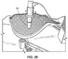
- FIG. 26is a partial perspective view of an exemplary testing apparatus.
- Seating structuresmay include any structure used to support a body of a user, for example, without limitation, office chairs, chairs, sofas, airplane seats, vehicle seats, bicycle seats, boat seats, beds, dental and medical seats and beds, auditorium and educational seating, etc. It should be understood that the various methods and devices disclosed herein may be applied to seating structures other than a seat and/or backrest, including for example and without limitation armrests, headrests and other ergonomic positioning features. In addition, the various methods and devices may be applied to structures employing a frame and suspension material other than seating structures. Although the illustrated embodiments are shown in connection with an office chair, other embodiments can include different configurations.
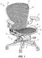
- FIG. 1shows an exemplary embodiment of a seating structure configured as a chair that includes a seat 2 , a backrest 4 and a base 6 .
- the baseincludes a tilt control housing 8 , a support column 10 coupled to and supporting the tilt control housing 8 and a base structure 12 coupled to and supporting the support column 10 .
- a pair of armrests 11may be connected to the chair.
- the seat 2includes a frame 14 , a suspension material 16 , and a carrier 18 .
- the carrier 18retains the suspension material 16 and connects to the frame 14 .
- the frame 14is formed as a ring having a front, a back, and a pair of sides defining an opening.
- the frame 14may also be formed from side members, a top member, and a bottom member. Different sizes, shapes, and configurations of the frame 14 can be used according to aesthetics, ergonomics, space, or other considers.
- the frame 14may be integrally formed as a single, homogenous unit, or formed of separate components.
- the backrest 4includes a frame 20 , a suspension material 22 , and a carrier 24 .
- the carrier 24retains the suspension material 22 and connects to the frame 20 .
- the frame 20is formed as a ring having a front, a back, and a pair of sides defining an opening.
- the frame 20may also be formed from side members, a top member, and a bottom member. Different sizes, shapes, and configurations of the frame 20 can be used according to aesthetics, ergonomics, space, or other considers.
- the frame 20may be integrally formed as a single, homogenous unit, or formed of separate components.
- suspension material 16 , 22can be used, including bonding and adhesive or mechanical fasteners, such as staples, or in-molding.
- the suspension material 16 , 22may be made of a woven or knit material, including various elastomeric materials, or fabrics, or various molded polymeric materials.
- the seat 2 and backrest 4may utilize the same type of material or different materials for the suspension material 16 , 22 .
- the suspension material 16 , 22can include a plurality of monofilaments 26 interlaced with a plurality of multifilament strands 28 as best shown in FIG. 2 .
- the monofilaments 26can be the primary load carrying members and run laterally in the warp direction of the seat 2 and backrest 4 while the multifilament strands 28 run longitudinally in the weft direction. Additionally, monofilaments 26 and/or multifilaments 28 may be combined to run in both the lateral and longitudinal directions if necessary.
- suspension material 16 , 22may be attached to the frame 14 , 20 in other suitable ways, such as by directly attaching the suspension material 16 , 22 to the frame 14 , 20 without a carrier 18 , 24 , including by molding, bonding, mechanical fasteners, other know devices, and combinations thereof.
- the suspension material 16 , 22can include different zones.
- the zonescan be designed to increase the comfort and/or support of the seating structure for a user.
- Different zonescan include different levels of stiffness or flexibility.
- Differential zones of stiffness in the suspension material 16 , 22may be developed in different ways related to the construction of the suspension material, and the process for introducing tension.
- One exemplary embodiment of creating different stiffness in the suspension material 16 , 26includes engineered textiles (ET).
- ETengineered textiles
- the type, number, and spacing of monofilaments 26 and multifilaments 28are adjusted to create different levels of stiffness.
- the orientation of the monofilaments 26can be changed from longitudinal to lateral in certain areas to achieve a high tension zone.
- monofilaments 26 and/or multifilaments 28may be combined to run in both the lateral and longitudinal directions if necessary.
- Monofilaments 26 and multifilaments 28 having different elastic moduluscan also be used in different zones to increase or decrease stiffness.
- the density of monofilaments 26 and multifilaments 28can also be adjusted to increase or decrease stiffness.
- a standard monofilament 26has a 55 shore D durometer with an elastic modulus of 180 Mpa, and the level of stiffness is decreased or increased in different zones as needed.
- the term standard stiffnesscan also be used to mean an industry, brand, or model standard or the relative general stiffness of other parts of a seating structure or suspension material.
- Monofilaments 26 and multifilaments 28 having different levels of stretchcan also be used in different zones.
- TESthermally engineered suspension
- energyis applied to the suspension material 16 , 22 to alter its stiffness.
- the energycan come from a variety of different sources including high temperature steam application, forced hot air, laser, microwaves, high output UV, infrared emitter, plasma, and/or contact heat.
- the suspension material 16 , 22can be altered before or after being placed into the carrier 18 , 24 or the frame 14 , 20 .
- ET and TESthere are many other sub-paths that vary the mechanical properties, zonal pre-tension and weave patterns.
- FIG. 3shows a backrest 4 and an example of a breakdown of different anatomical zones associated with a user's back.
- the zonesinclude central zones 30 A-D, upper side zones 32 A, 32 B, middle side zones 34 A, 34 B, lower side zones 36 A, 36 B, shoulder socket zones 38 A, 38 B, and arm zones 50 A, 50 B.
- the support of these zonescan be controlled by adjusting the stiffness in each area.
- the central zones 30 A-Dare provided with a first stiffness or stiffness range
- the middle side zones 34 A, 34 Bare provided with a second stiffness or stiffness range
- the upper side zones 32 A, 32 B and lower side zones 36 A, 36 Bare provided with a third stiffness or stiffness range.
- the central zones 30 A- 30 Dare approximately 2 inches wide to approximately 6 inches wide. For example approximately 3 inches wide to approximately 5 inches wide. The size, number and spacing of the zones can be varied.
- the first stiffness or rangecan be configured to provide support
- the second stiffness or rangecan be configured to provide stability
- the third stiffness or rangecan be configured to relieve pressure or stress.
- thiscan mean that the second stiffness or range is less than the first stiffness or range and the third stiffness or range is less than the second stiffness or range.
- the stiffness of the central zones 30 A-Dcan vary or be variable, for example increasing from the top zone 30 A to the bottom zone 30 D, with each zone having a greater stiffness than the second stiffness or range.
- FIG. 4shows an exemplary embodiment of a chair having a seat 2 and a backrest 4 .
- the backrest 4has a central zone 42 , and side zones 44 A, 44 B.
- the central zone 42has a stiffness or range greater than the side zones 44 A, 44 B.
- the seat 2also has a central zone 46 , and side zones 48 A, 48 B.
- the central zone 46has a stiffness or range greater than the side zones 48 A, 48 B.
- FIG. 5shows a backrest 4 having a central zone 50 with a first stiffness or range, top side zones 52 A, 52 B with a second stiffness or range, shoulder zones 54 A, 54 B with a third stiffness or range, and lower zones 56 A, 56 B with a fourth stiffness or range.
- the central zone 50 and the top side zones 52 A, 52 Bcan have a greater stiffness than the shoulder zones 54 A, 54 B and the lower zones 56 A, 56 B.
- central zone 50 and the top side zones 52 A, 52 Bhave a stiffness that is greater than a standard stiffness, for example up to 4 times the standard stiffness and the shoulder zones 54 A, 54 B can have a stiffness that is less than the standard stiffness, for example from the standard stiffness to half the standard stiffness.
- the central zone 50 and the top side zones 52 A, 52 Bcan be combined in a T configuration.
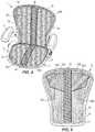
- FIG. 6shows a backrest 4 having a central zone 60 , top side zones 62 A, 62 B, upper side zones 64 A, 64 B, middle side zones 66 A, 66 B, and lower side zones 68 A, 66 B, with each zone having a stiffness or stiffness range.
- the central zone 60has the greatest stiffness or range and the top side zones 62 a , 62 B and the middle side zones 66 A, 66 B have a stiffness or range greater than the upper side zones 64 A, 64 B and the lower side zones 68 A, 68 B.
- the central zone 60 and the top side zones 62 A, 62 Bcan be combined in a T configuration, the central zone 60 can be combined with the middle side zones 66 A, 66 B in a cross-configuration, or a combination therefore.
- FIG. 7shows a backrest 4 having a top zone 70 , an upper zone 72 , a middle side zone 74 , and a lower zone 76 , with each zone having a stiffness or stiffness range.
- the top zone 70 and the middle zone 74have a stiffness or range greater than the upper side zone 72 and the lower zone 76 .
- FIG. 8shows a seat 2 having a front zone 80 , a middle zone 82 , and a rear zone 84 , with each zone having a stiffness or stiffness range.
- the front zone 80has a greater stiffness or range than the middle zone 82 and the middle zone 82 has a greater stiffness or range than the rear zone 84 .
- the front zone 80has a stiffness or range up to three times or four times a standard stiffness
- the middle zone 82has a standard stiffness
- the rear zone 84has a stiffness or range from the standard stiffness to half the standard stiffness.
- the seatmay be provided with just a front and rear zone with the front zone having a stiffness or stiffness range greater than the rear zone.
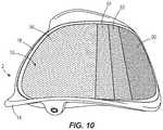
- FIGS. 9 and 10show a seat 2 having a front zone 90 , a first middle zone 92 , a second middle zone 94 and a rear zone 96 , with each zone having a stiffness or stiffness range.
- the stiffness or rangedecreases from the front to the rear of the seat 2 .
- the front zone 90has a stiffness or range up to four times a standard stiffness
- the first middle zone 92has a stiffness or range up to three times a standard stiffness
- the second middle zone 94has a stiffness or range up to two times a standard stiffness
- the rear zone 86has a standard stiffness.
- FIG. 11shows a seat 2 having a front zone 100 , a middle zone 102 , and a rear zone 104 , with each zone having a stiffness or stiffness range.
- the suspension material 16also includes a first transition zone 106 and a second transition zone 108 .
- the front zone 100has a greater stiffness or range than the middle zone 102 and the middle zone 102 has a greater stiffness or range than the rear zone 104 .
- the first transition zone 106has a stiffness or range between that of the front zone 100 and the middle zone 102 and the second transition zone 108 has a stiffness or range between that of the middle zone 102 and the rear zone 104 .
- the transition zones 106 , 108are approximately 0.5 inches in width.
- FIG. 12shows a seat 2 having a front zone 110 , side zones 112 A and 112 B, and a rear zone 114 , with each zone having a stiffness or stiffness range.
- the suspension material 16also includes side transition zones 116 A, 116 B and a rear transition zone 118 .
- the front zone nohas a greater stiffness or range than the side zones 112 A, 112 B and the side zones 112 A, 112 B have a greater stiffness or range than the rear zone 114 .
- the side transition zones 116 A, 116 Bhave a stiffness or range between that of the front zone no and the side zones 112 A, 112 B and the rear transition zone 118 has a stiffness or range between that of the side zones 112 A, 112 B, and the rear zone 114 .
- FIG. 13shows a seat 2 having a front zone 120 , a rear zone 122 , and pocket zones 124 A, 124 B, with each zone having a stiffness or stiffness range.
- the front zone 120has a greater stiffness or range than the middle zone 122 and the middle zone 122 has a greater stiffness or range than the pocket zones 124 A, 124 B.
- FIG. 14shows a seat having a front zone 130 , a first middle zone 132 , a second middle zone 134 , and a rear zone 136 , with each zone having a stiffness or stiffness range.
- the first zonehas a first stiffness or range
- the second zonehas a second stiffness or range lower than the first stiffness or range
- the third zonehas a third stiffness or range lower than the first stiffness or range and lower than the second stiffness or range
- the fourth zonehas a fourth stiffness or range lower than the first stiffness or range and higher than the second and third stiffness or range.
- the third zonehas a standard stiffness
- the second zonehas approximately 1.2 times the standard stiffness
- the first zonehas approximately 3 times the standard stiffness
- the fourth zonehas approximately 2 times the standard stiffness.
- the size, number, and spacing of the zonescan be varied according to different considerations, for example ergonomic considerations.
- the greater stiffness zones or rangesinclude higher elastic modulus monofilaments 26 , monofilaments 26 running in more than one direction, or a greater density of monofilaments 26 .
- the greater stiffness zones or rangesinclude monofilaments 26 that are stretched a greater amount than other areas, for example, a 3% increase in stretch (displacement), which may correspond to about 0.95 inches greater stretch for a blank size of 31.5 inches, with the understanding that displacement depends on blank size.
- the monofilaments 26 in the greater stiffness zones or rangeshave a modulus from approximately two to six times the elastic modulus of a standard monofilament, while the lower side zones have an elastic modulus up to one half the standard monofilament, meaning, for example, that the center zones 50 , 60 and side zones 56 A-B, 64 A-B have a stiffness ratio from 4:1 to 6:1.
- the fibershave ratios relative to a standard monofilament in the range of 0.75:x to 2.25:x based on changing elastic modulus only.
- stiffnesscan be reduced in the soft, flexible, or other less stiff zones or ranges, for example the upper side zones 64 A, 64 B and lower side zones 68 A, 68 B shown in FIG. 6 by using monofilaments 26 and/or multifilaments 28 with a lower elastic modulus.
- Another method to reduce tensionis by eliminating monofilaments within a zone.
- FIG. 15shows a standard region 140 and a second region 142 having a reduced stiffness.
- one out of three or four monofilamentsare eliminated to provide a reduced stiffness, for example to provide an area for the user's shoulder blades to sink into.
- the multifilaments 28may also be decoupled from the monofilaments 26 to make the regions less stiff, or the density of monofilaments 26 may be reduced in these areas, which may increase the space between monofilaments 26 .
- the stiffnesscan be that of the standard or it can be less, for example between approximately 0.25 standard and the standard level of stiffness.
- One exemplary embodiment of controlling the stiffness in the transition zonesis to use a combination of higher modulus monofilaments 26 A and lower modulus monofilaments 26 B in a single region as shown in FIG. 16 .
- the number and spacingcan vary as needed.
- FIG. 16shows alternating pairs but the higher and lower monofilaments 26 A, 26 B may also be interwoven with one crossing strand being a higher modulus monofilament 26 A and the other being a lower modulus monofilament 26 B.
- Other ways of altering the stiffness in the transition zonessuch as controlling the density or any other method discussed herein, may also be used.
- ETis used to adjust the stiffness of the suspension material 16 , 22 .
- the mechanical properties of the suspension material 16 , 22e.g., elastic modulus/durometer
- the stretch rate of the suspension material 16 , 22 in different zonesmay be varied, for example by locally stretching certain zones to achieve high tension areas.
- the monofilament 26 densitymay be varied across the suspension, e.g., with more fibers being provided in higher tension areas. It should be understood that combinations of these various methods may also be employed.
- an apparatus for making a suspension member 16 with differential stiffnessincludes a support frame 150 or bed, and a first plurality of clamping elements 152 connected to and independently moveable relative to the frame 150 in at least a first direction.
- the clamping elements of the first plurality 152each include a clamping head 154 moveable between a clamped and released position.
- a second plurality of clamping elements 156are also connected to and independently moveable relative to the frame 150 in at least a second direction orthogonal to the first direction.
- the clamping elements of the second plurality 156also each include a clamping head 154 moveable between a clamped and release position. It should be understood that the second plurality 156 may be omitted, or that a single clamping element extending along the length of the blank may be provided as shown in FIG. 17 .
- the apparatusmay also include a third plurality of clamping elements 160 and a fourth plurality of clamping elements 162 spaced apart respectively from the first and second pluralities 152 , 156 , with the third and fourth pluralities 160 , 162 also being independently moveable relative to the frame 150 , and relative to the opposite first and second pluralities 152 , 156 .
- the third and fourth pluralities 160 , 162may be stationary.
- the third and fourth pluralities 160 , 162may be replaced by a single third and fourth clamping element, whether moveable or stationary.
- the number of clamping heads 154 in the second plurality 156is greater than the first plurality 152 .
- the first plurality 152includes between 2 and 15 clamping elements, and may include 5-6 clamping elements, and in one embodiment, 13 clamping elements.
- 11 clamping elementsare provided for the vertical zones (top to bottom of backrest 4 and front to back of seat 2 ) and 13 clamping elements are provided for the horizontal zones (side to side of backrest 4 and seat 2 ).
- a plurality of clamping elementsare individually moved by a corresponding plurality of actuators 164 , with each actuator 164 controlled to axially move a respective clamping element.
- the actuators 164may be pneumatic, for example driven by air, or electro-mechanical, for example servo motors driving spindles.
- Clamping elements 154are secured to rods 157 having collars 167 .
- the collar 167may be adjustably positioned along the shaft of the rod 157 , so as to vary the distance D between the clamping element and collar 167 .
- a cross bar 170then engages the collars 167 , with the clamping elements 154 having a shorter distance D between the clamping element 154 and collar 167 being engaged by the cross bar 170 first, and thereby successively applying more tension than the other clamping elements having a respectively longer distance D.
- a subassemblyincludes a pair of macro actuators 168 connected to the frame cross bar 170 . It should be understood that a single actuator 168 may suffice.
- the individual clamping elementsare secured to rods 166 configured with collars 167 .
- the collars 167may be independently positioned along a respective rod 166 , and relative to the cross bar 170 , for example by adjustably threading the collars, or with set screws or other clamping arrangements.
- the cross bar 170is then movable relative to the rods 166 . This provides for independent stretch control of each clamping element.
- the apparatusalso includes a loom 180 configured with first and second loom members 182 , 184 positionable adjacent and between the first, second, third and fourth pluralities of clamping members.
- the loom 180defines a perimeter and interior area, with some of the clamping members lying outside of perimeter/area of the loom perimeter/area.
- the method of making a suspension member 16 with differential stiffnessincludes providing a blank of suspension material, which is positioned over a lower loom member 184 .
- the first, second, third and fourth pluralities of clamping membersare clamped onto, and engage the blank, although fewer clamping members are utilized depending on the number of pluralities of clamping members.
- a controller 200sends a control signal to the plurality of actuators 164 , which are independently linearly moveable, such that the blank is stretched by the clamping members. Alternatively, the collars 167 are moved to predetermined positions on their respective rods 166 , and the clamping members are engaged with the blank of suspension material 16 .
- the controller 200sends a control signal to the macro actuators 168 , such that that cross bar 170 is moved and successively picks up, or engages, the collars 167 and moves the corresponding clamping members to induce the predetermined and desired stretch.
- the blankmay be stretched different amounts by each clamping member, thereby inducing a different amount of tension to different zones of the blank of suspension material, and thereby making the blank the same, more, or less stiff in each zone relative to other zones.
- a center one of the first plurality of clamping members 152is moved a greater distance than the other ones of the first plurality, such that a central zone is provided with additional tension, and resulting stiffness.
- an upper loom member 182is secured to the lower loom member 184 , thereby clamping the blank between the loom members in the desired stretched condition.
- the clamping membersmay then be released, with the loom 180 retaining the blank in the differentially stretched configuration.
- the loom 180 and stretched blankmay then be positioned in a mold tool 186 , such that the carrier member 18 , 24 may be molded to the blank.
- the blankmay be released from the loom, and any excess edge material trimmed from the outside of the carrier member 18 , 24 .
- the suspension member 16 , 22is then ready for installation on a seating structure frame.
- TEScan be used to adjust the stiffness of the suspension material 16 .
- TES monofilament and multifilament chemistry and processprovides for a suspension material 16 to be tensioned via application of energy to the material after it is encapsulated into a carrier 18 and/or frame system 14 .
- the flexibility of the TES processallows for localized energy application and tensioning to create zonal suspension properties across a seating surface, including for example and without limitation, the various zones described herein respect to the seat 2 and backrest 4 .
- a global energy applicationmay create a zonal tension pattern by varying the mechanical properties of the suspension material 16 locally through the pattern of the fabric as also described herein.
- TES fabriccan be produced in a woven (Leno or Jacquard) or a knit construction, for example 3D, circular, flat bed, and/or known knitting processes.
- a woven materialalthough embodiments may use a similar concept in a knitted construction.
- the TES monofilament and multifilament constructionincludes high shrinkage filament chemistry, for example (Polyester Elastomer, TPC-ET) 5556/5556RS Hytrel and DSM alternatives.
- the properties of the suspension material 16may be varied by altering the mechanical properties, the size of the filament, the shape of the filament (e.g., oval filament size to minimize carrier flashing), the density of the filaments in the weave pattern, the shrink characteristics of the material (e.g., high shrinkage material), the denier of multifilament (e.g., 1400-2900, and may be between 1500 and 2000, or 1600 vs. typical 2900 for conventional suspension materials), and durometer ranges from 40 to 75 (conventional suspension materials are about 55 durometer).
- the suspension material 16is molded into the carrier frame 18 in a relaxed state, for example with little to no pre-tension. In one example the suspension material 16 is molded with less than approximately 5% stretch, or approximately 0 to 5% stretch. In another example the suspension material 16 is molded with less than approximately 5% stretch.
- energymay be applied by an energy source 210 globally and/or locally to achieve the desired zoned stiffness properties, for example as described above.
- the surface of the suspension materialmay also be shielded with a shield 212 to achieve the zoned properties.
- a zone of desired less stiffnessmay be shielded with the shield 212 during the application of the energy from the source 210 so that less shrinkage is induced.
- Process variables that can be used to control the tensioninginclude Time, Distance, Temperature and Power of the heat source.
- the energy sourcemay include: high temperature steam application, forced hot air, laser, microwaves, high output UV, infrared emitter, plasma, and/or contact heat.
- portions or an entirety of the suspension material 16may be put in tension when the suspension material 16 is attached to the frame 14 .
- tensionmay be introduced to the suspension material 16 , or increased as desired, after the suspension material 16 is attached to the frame 14 .
- the tensioncan be introduced prior to attachment to the frame 14 .
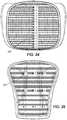
- FIG. 24shows 15 measurement points 240 for the seat 2 and FIG. 25 shows 9 measurement points 250 for the backrest 4 .
- IFD testis described in US Publication 2013/0099548 A1, the entire disclosure of which is hereby incorporated herein by reference.
- a global 6 inch diameter IFD measurementis used to measure the suspension response. This measurement technique does not provide enough resolution to the zonal suspension properties being created by the present embodiments.
- a smaller 1 or 1.5 inch diameter indentor 260is used to study the suspension performance in a grid pattern.
- the terms “front,” “rear,” “upper,” “lower,” “upwardly,” “downwardly,” and other orientational descriptorsare intended to facilitate the description of the exemplary embodiments of the present application, and are not intended to limit the structure of the exemplary embodiments of the present application to any particular position or orientation.
- Terms of degree, such as “substantially” or “approximately”are understood by those of ordinary skill to refer to reasonable ranges outside of the given value, for example, general tolerances associated with manufacturing, assembly, and use of the described embodiments.
Landscapes
- Engineering & Computer Science (AREA)
- Mechanical Engineering (AREA)
- Textile Engineering (AREA)
- Chemical & Material Sciences (AREA)
- Composite Materials (AREA)
- Chair Legs, Seat Parts, And Backrests (AREA)
- Pharmaceuticals Containing Other Organic And Inorganic Compounds (AREA)
- Woven Fabrics (AREA)
- Seats For Vehicles (AREA)
Abstract
Description
Claims (23)
Priority Applications (3)
| Application Number | Priority Date | Filing Date | Title |
|---|---|---|---|
| US14/996,964US10874220B2 (en) | 2015-01-16 | 2016-01-15 | Zoned suspension seating structure |
| US15/298,963US20170035094A1 (en) | 2013-02-12 | 2016-10-20 | Methods and diets to protect against chemotoxicity and age related illnesses |
| US17/088,282US11825957B2 (en) | 2015-01-16 | 2020-11-03 | Zoned suspension seating structure |
Applications Claiming Priority (3)
| Application Number | Priority Date | Filing Date | Title |
|---|---|---|---|
| US201562104332P | 2015-01-16 | 2015-01-16 | |
| US201562164938P | 2015-05-21 | 2015-05-21 | |
| US14/996,964US10874220B2 (en) | 2015-01-16 | 2016-01-15 | Zoned suspension seating structure |
Related Child Applications (1)
| Application Number | Title | Priority Date | Filing Date |
|---|---|---|---|
| US17/088,282DivisionUS11825957B2 (en) | 2015-01-16 | 2020-11-03 | Zoned suspension seating structure |
Publications (2)
| Publication Number | Publication Date |
|---|---|
| US20160206102A1 US20160206102A1 (en) | 2016-07-21 |
| US10874220B2true US10874220B2 (en) | 2020-12-29 |
Family
ID=56406470
Family Applications (2)
| Application Number | Title | Priority Date | Filing Date |
|---|---|---|---|
| US14/996,964Active2037-04-11US10874220B2 (en) | 2013-02-12 | 2016-01-15 | Zoned suspension seating structure |
| US17/088,282Active2037-03-17US11825957B2 (en) | 2015-01-16 | 2020-11-03 | Zoned suspension seating structure |
Family Applications After (1)
| Application Number | Title | Priority Date | Filing Date |
|---|---|---|---|
| US17/088,282Active2037-03-17US11825957B2 (en) | 2015-01-16 | 2020-11-03 | Zoned suspension seating structure |
Country Status (7)
| Country | Link |
|---|---|
| US (2) | US10874220B2 (en) |
| EP (2) | EP3244777B1 (en) |
| JP (1) | JP2018501909A (en) |
| CN (1) | CN107105900A (en) |
| AU (1) | AU2016206557B2 (en) |
| BR (1) | BR112017014533A2 (en) |
| WO (1) | WO2016115488A1 (en) |
Cited By (9)
| Publication number | Priority date | Publication date | Assignee | Title |
|---|---|---|---|---|
| US20210227992A1 (en)* | 2018-08-03 | 2021-07-29 | Illinois Tool Works Inc. | Load bearing surface with kinetic energy management fabric |
| US20220039554A1 (en)* | 2020-08-06 | 2022-02-10 | Illinois Tool Works Inc. | Apparatus and method for manufacturing a fabric suspension seat structure |
| US11330905B2 (en) | 2007-09-20 | 2022-05-17 | MillerKnoll, Inc. | Load support structure |
| US11452380B2 (en)* | 2018-10-25 | 2022-09-27 | Illinois Tool Works Inc. | Seat comprising suspension fabric with compression limiters |
| US11464340B2 (en)* | 2018-08-03 | 2022-10-11 | Illinois Tool Works Inc. | Suspension seating surface edge encapsulation method, seating surface carrier and seat made therewith |
| US11602225B2 (en)* | 2020-06-25 | 2023-03-14 | Haworth, Inc. | Knit seat back for an office chair |
| US11825957B2 (en) | 2015-01-16 | 2023-11-28 | MillerKnoll, Inc. | Zoned suspension seating structure |
| US12070132B2 (en) | 2022-09-09 | 2024-08-27 | MillerKnoll, Inc. | Seating structure having a knitted suspension material |
| US20240285080A1 (en)* | 2021-06-24 | 2024-08-29 | Roland Zwick | Seat element |
Families Citing this family (13)
| Publication number | Priority date | Publication date | Assignee | Title |
|---|---|---|---|---|
| US10182656B2 (en) | 2015-04-13 | 2019-01-22 | Steelcase Inc. | Seating components with laminated bonding material |
| JP6439724B2 (en)* | 2016-03-16 | 2018-12-19 | トヨタ自動車株式会社 | Vehicle seat |
| US9987949B2 (en)* | 2016-08-12 | 2018-06-05 | Herman Miller, Inc. | Seating structure including a presence sensor |
| US12209360B2 (en)* | 2018-12-21 | 2025-01-28 | Quantum Materials, Llc | Synthetic leather fabrics |
| IT201900011508A1 (en)* | 2019-07-11 | 2021-01-11 | Dv8 Id S R L | FABRIC FOR MODULAR CHAIR |
| US11186336B2 (en) | 2019-07-22 | 2021-11-30 | Specialized Bicycle Components, Inc. | Bicycle saddle |
| DE102020109174A1 (en) | 2019-09-16 | 2021-03-18 | Grammer Aktiengesellschaft | Seat arrangement for a means of transport |
| DE102019129871A1 (en)* | 2019-11-06 | 2021-05-06 | König + Neurath AG | Seating |
| US12215445B2 (en) | 2020-07-31 | 2025-02-04 | Herman Miller, Inc. | System and method of manufacturing suspension member |
| USD990180S1 (en) | 2021-04-30 | 2023-06-27 | Specialized Bicycle Components, Inc. | Bicycle saddle |
| NL2029202B1 (en)* | 2021-09-17 | 2023-03-24 | P R Sella B V | A sitting |
| WO2023168348A2 (en) | 2022-03-03 | 2023-09-07 | MillerKnoll, Inc. | Cover assembly for a chair |
| US20240156265A1 (en)* | 2022-11-11 | 2024-05-16 | MillerKnoll, Inc. | Seating structure having a support pocket |
Citations (158)
| Publication number | Priority date | Publication date | Assignee | Title |
|---|---|---|---|---|
| US488095A (en) | 1892-12-13 | Knockdown folding chair | ||
| US693197A (en) | 1901-11-20 | 1902-02-11 | Charles B White | Knockdown chair. |
| US946225A (en) | 1909-03-15 | 1910-01-11 | Paul Irwin J | Seat. |
| US2771122A (en) | 1953-08-28 | 1956-11-20 | Straub Carl | Removable cover lawn chair |
| US3041109A (en) | 1958-09-29 | 1962-06-26 | Miller Herman Inc | Web and spreader furniture construction |
| US3120407A (en) | 1961-06-05 | 1964-02-04 | Miller Herman Inc | Net seating |
| US3208794A (en) | 1964-08-31 | 1965-09-28 | Air Lab Service Co Inc | Cover for aircraft seat |
| US3230011A (en) | 1963-07-05 | 1966-01-18 | Miller Herman Inc | Seating |
| US3300251A (en) | 1965-06-10 | 1967-01-24 | Knoll Associates | Upholstery cover-frame connection |
| US3375313A (en)* | 1959-12-12 | 1968-03-26 | Bayer Ag | Process for the continuous biaxial stretching of a traveling sheet |
| US3565482A (en) | 1968-06-24 | 1971-02-23 | Leif Blodee | Adjustable contour chair |
| US3586370A (en) | 1968-12-04 | 1971-06-22 | American Seating Co | Upholstered chair |
| US3640576A (en) | 1970-06-08 | 1972-02-08 | Art Metal Knoll Corp | Furniture construction |
| US3669496A (en) | 1970-12-03 | 1972-06-13 | American Desk Mfg Co | Chair and seat and back unit therefor |
| US3844612A (en) | 1972-03-14 | 1974-10-29 | K Borggren | Arrangement in seating furniture or seats for attaching seat and back supporting elements |
| US3877750A (en) | 1972-08-05 | 1975-04-15 | Porsche Ag | Reposing furniture |
| US3914103A (en)* | 1974-09-23 | 1975-10-21 | Formex Mfg Inc | Abstract having product ejection means for forming plastic |
| US4036527A (en) | 1975-04-10 | 1977-07-19 | Otaco Limited | Transportation seating construction and system |
| US4062590A (en) | 1976-05-24 | 1977-12-13 | Fixtures Manufacturing Corporation | Chair structure |
| US4230365A (en) | 1979-01-18 | 1980-10-28 | Alexander Messinger | Article of furniture and method of manufacture |
| EP0049310A1 (en) | 1980-10-01 | 1982-04-14 | Wilkhahn Wilkening + Hahne GmbH + Co. | Working chair |
| AU6563380A (en) | 1979-12-19 | 1983-01-06 | Mckinlay, I.B. | Foils operating in fluid medium |
| US4522444A (en) | 1982-09-15 | 1985-06-11 | Charles Pollock | Stacking chair |
| US4529247A (en) | 1982-04-15 | 1985-07-16 | Herman Miller, Inc. | One-piece shell chair |
| US4585272A (en) | 1982-10-22 | 1986-04-29 | Castelli S.P.A. | Chair having a back comprising a plurality of articulated segments |
| US4592126A (en) | 1984-12-14 | 1986-06-03 | Homecrest Industries Incorporated | Method for constructing furniture having a flexible sheet portion |
| US4601516A (en) | 1984-03-16 | 1986-07-22 | Klein Gerhart P | Contoured chair |
| EP0250109A1 (en) | 1986-06-13 | 1987-12-23 | Betz Europe, Inc. | Colour stabilized distillate fuel oil composition and its production |
| US4889385A (en) | 1988-03-09 | 1989-12-26 | American Seating Company | Chair seat-and-back support |
| US4913493A (en) | 1987-09-22 | 1990-04-03 | Strafor S.A. | Flexible structure |
| US5100713A (en)* | 1989-06-06 | 1992-03-31 | Toray Industries, Inc. | Reinforcing woven fabric and preformed material, fiber reinforced composite material and beam using it |
| US5102196A (en) | 1988-08-31 | 1992-04-07 | Kokuyo Co., Ltd. | Chair provided with a backrest |
| US5114210A (en) | 1989-01-11 | 1992-05-19 | Maxton Fox Commercial Furniture Pty. Ltd. | Tilting chair with improved lumbar support |
| US5240308A (en) | 1983-11-09 | 1993-08-31 | Goldstein Glenn A | Ergonomic adjustable chair and method |
| US5320410A (en) | 1992-01-14 | 1994-06-14 | Steelcase Inc. | Chair control |
| US5328245A (en) | 1992-10-30 | 1994-07-12 | Thomas J. Marks | Chair having adjustable back support |
| US5352022A (en) | 1986-04-10 | 1994-10-04 | Steelcase Inc. | Controlled deflection front lip for seating |
| FR2715124A1 (en) | 1993-12-01 | 1995-07-21 | Ballu Arnaud | Rigging for sailing boats |
| LU88528A1 (en) | 1994-09-01 | 1996-03-18 | Laurent Thirkell | Hydrodynamic structure with variable profile |
| DE4433663A1 (en) | 1994-09-21 | 1996-03-28 | Gotthard Bresch | Chair with subframe seat and backrest |
| US5518294A (en) | 1993-04-05 | 1996-05-21 | Ligon Brothers Manufacturing Company | Variable apex back support |
| DE29505064U1 (en) | 1995-03-25 | 1996-07-25 | Heerklotz, Siegfried, Dipl.-Ing., 49143 Bissendorf | Flat cushion body |
| USD377431S (en) | 1994-09-29 | 1997-01-21 | Herman Miller, Inc. | Seat and back unit for a chair |
| US5649743A (en) | 1995-01-31 | 1997-07-22 | Victor Stanley, Inc. | Vandal-resistant bench and frame therefor |
| US5660439A (en) | 1995-01-04 | 1997-08-26 | Unwalla; Jamshed | Integrated seat and back and mechanisms for chairs |
| US5664835A (en) | 1994-03-25 | 1997-09-09 | Peter Roeder | Chair |
| USD386023S (en) | 1996-09-13 | 1997-11-11 | Herman Miller, Inc. | Seat and back unit for a chair |
| USD390026S (en) | 1996-04-18 | 1998-02-03 | Kabushiki Kaisha Sazaby | Chair |
| WO1998019578A1 (en) | 1996-11-08 | 1998-05-14 | Chow William W | Therapeutic sling seat |
| EP0860355A1 (en) | 1997-02-25 | 1998-08-26 | Deutsches Zentrum für Luft- und Raumfahrt e.V. | Aerodynamic structure with variable camber such as landing flaps, airfoil, horizontal and vertical stabilizer |
| US5842264A (en) | 1991-05-30 | 1998-12-01 | Steelcase Inc. | Chair construction and method of assembly |
| US5918935A (en) | 1997-06-03 | 1999-07-06 | Stulik; Edward L. | Reclining chair |
| US5954399A (en) | 1998-07-15 | 1999-09-21 | Hong; Jung-Myung | Lumbar support for a car seat |
| US5975634A (en) | 1997-10-24 | 1999-11-02 | Steelcase Development Inc. | Chair including novel back construction |
| US6015187A (en) | 1997-04-30 | 2000-01-18 | Haworth, Inc. | Tilt control for chair |
| US6050646A (en) | 1997-12-10 | 2000-04-18 | Sedus Stoll Ag | Backrest |
| US6059368A (en)* | 1992-06-15 | 2000-05-09 | Herman Miller, Inc. | Office chair |
| DE19916411A1 (en) | 1999-04-01 | 2000-11-16 | Leif Kniese | Dynamic lever to improve power transmission |
| USD436260S1 (en) | 1999-11-08 | 2001-01-16 | Okamura Corporation | Chair |
| USD436259S1 (en) | 1999-11-08 | 2001-01-16 | Okamura Corporation | Chair |
| USD437132S1 (en) | 1999-11-08 | 2001-02-06 | Okamura Corporation | Chair |
| US6193318B1 (en) | 1998-06-25 | 2001-02-27 | Daimlerchrysler Ag | Seat arrangement |
| USD441977S1 (en) | 2000-04-13 | 2001-05-15 | Bernhardt, L.L.C. | Chair |
| US6234573B1 (en) | 1998-05-27 | 2001-05-22 | Peter Röder | Chair, in particular office chair |
| USD442383S1 (en) | 2000-09-06 | 2001-05-22 | Ted Allen Bell | Chair |
| US6254190B1 (en)* | 1999-09-29 | 2001-07-03 | Peter G. G. Gregory | Chair having a seat with differential front and rear support portions |
| USD444309S1 (en) | 1999-11-08 | 2001-07-03 | Okamura Corporation | Chair |
| US6257665B1 (en) | 1998-07-09 | 2001-07-10 | Okamura Corporation | Chair |
| EP1177935A2 (en) | 2000-08-02 | 2002-02-06 | Delta Tooling Co., Ltd. | Vehicle seat |
| US6439665B1 (en) | 2000-06-09 | 2002-08-27 | Stylex | Ergonomic chair with mesh seat and back |
| USD465347S1 (en) | 2001-10-19 | 2002-11-12 | Ted Allen Bell | Chair |
| US20030001420A1 (en)* | 2001-06-15 | 2003-01-02 | Koepke Marcus C. | Ergonomic chair |
| US6505890B2 (en) | 2001-02-07 | 2003-01-14 | Am-Safe, Inc. | Aircraft seat structure |
| USD469618S1 (en) | 2000-11-01 | 2003-02-04 | Okamura Corporation | Chair |
| US6513874B1 (en) | 1999-06-17 | 2003-02-04 | Konig & Neurath Ag | Chair, especially office chair |
| USD469970S1 (en) | 2001-11-13 | 2003-02-11 | B.Z.B. — Spa | Chair without arms |
| US6540950B1 (en)* | 2000-09-20 | 2003-04-01 | Dahti, Inc. | Carrier and attachment method for load bearing fabric |
| US6572190B2 (en) | 2001-06-15 | 2003-06-03 | Hon Technology Inc. | Lumbar support for a chair |
| USD476493S1 (en) | 2000-11-01 | 2003-07-01 | Okamura Corporation | Chair |
| USD476820S1 (en) | 2000-11-01 | 2003-07-08 | Okamura Corporation | Chair |
| US6609754B2 (en) | 1997-09-24 | 2003-08-26 | Arjuna Indraeswaran Rajasingham | Easy ejector seat with skeletal crash safety beam |
| US20030189367A1 (en) | 2002-04-07 | 2003-10-09 | Christian Erker | Bucket seat with inclination-profile adjusting mechanism |
| USD481560S1 (en) | 2002-07-02 | 2003-11-04 | Hsn Improvements, Llc | Strut for a shoe storage rack |
| USD482542S1 (en) | 2002-09-11 | 2003-11-25 | Suncoast Aluminum Furniture, Inc. | Chair |
| US20030227211A1 (en) | 2002-06-07 | 2003-12-11 | Rowland David L. | Panel |
| US20040032156A1 (en) | 1995-06-07 | 2004-02-19 | Grant Stipek | Furniture with molded frame |
| USD487359S1 (en) | 2002-09-09 | 2004-03-09 | Okamura Corporation | Chair |
| USD489542S1 (en) | 2002-09-09 | 2004-05-11 | Okamura Corporation | Chair |
| EP1454571A1 (en) | 2002-08-07 | 2004-09-08 | Delta Tooling Co., Ltd. | Thin sheet |
| US6820933B2 (en) | 2000-06-19 | 2004-11-23 | Fico Cables, Lda | Spine support for vehicle seats |
| US6896328B2 (en) | 2002-12-18 | 2005-05-24 | Hon Technology Inc. | Steel wire chair with springs |
| CN1671316A (en) | 2002-07-23 | 2005-09-21 | 株式会社冈村制作所 | Construction for attaching net member to chair seat or backrest frame |
| USD509969S1 (en) | 2003-09-05 | 2005-09-27 | Steelcase Development Corporation | Seating unit |
| USD511629S1 (en) | 2003-06-25 | 2005-11-22 | Caldwell John W | Chair |
| USD512579S1 (en) | 2003-11-10 | 2005-12-13 | Okamura Corporation | Chair |
| USD512578S1 (en) | 2003-11-10 | 2005-12-13 | Okamura Corporation | Chair |
| US6986549B2 (en) | 2003-03-19 | 2006-01-17 | Leif Kniese | Seating element |
| USD513910S1 (en) | 2004-04-13 | 2006-01-31 | Gehry Frank O | Seat frame |
| USD514345S1 (en) | 2003-11-10 | 2006-02-07 | Okamura Corporation | Chair |
| USD514838S1 (en) | 2003-11-10 | 2006-02-14 | Okamura Corporation | Chair |
| US7055911B2 (en) | 2003-05-08 | 2006-06-06 | Haworth, Inc. | Mesh chair |
| USD526495S1 (en) | 2005-05-13 | 2006-08-15 | Lisa Albin | Rocking chair |
| US20060181126A1 (en) | 2005-02-16 | 2006-08-17 | Eysing Volker W | Support element |
| US7097249B2 (en) | 2002-07-23 | 2006-08-29 | Okamura Corporation | Tilting mechanism for a chair and chair having the same |
| USD527920S1 (en) | 2004-09-27 | 2006-09-12 | Okamura Corporation | Chair |
| US20060207296A1 (en)* | 2002-08-07 | 2006-09-21 | Kawashimaorimono Co., Ltd | Elastic fabric and elastic face material |
| USD528811S1 (en) | 2004-09-27 | 2006-09-26 | Okamura Corporation | Chair |
| USD528810S1 (en) | 2004-09-27 | 2006-09-26 | Okamura Corporation | Chair |
| USD528812S1 (en) | 2004-10-18 | 2006-09-26 | Okamura Corporation | Chair |
| US20060255645A1 (en)* | 2005-05-13 | 2006-11-16 | Coffield Timothy P | Elastomeric fabric load bearing surface |
| USD540557S1 (en) | 2005-12-29 | 2007-04-17 | Agio International Co., Ltd. | Chair |
| USD542580S1 (en) | 2004-03-03 | 2007-05-15 | Steelcase Development Corporation | Backrest |
| USD542549S1 (en) | 2005-11-10 | 2007-05-15 | Okamura Corporation | Chair |
| USD543039S1 (en) | 2005-11-10 | 2007-05-22 | Okamura Corporation | Chair |
| USD543040S1 (en) | 2005-11-10 | 2007-05-22 | Okamura Corporation | Chair |
| USD543041S1 (en) | 2005-11-10 | 2007-05-22 | Okamura Corporation | Chair |
| USD543042S1 (en) | 2005-11-10 | 2007-05-22 | Okamura Corporation | Chair |
| USD543371S1 (en) | 2005-07-11 | 2007-05-29 | Agio International Company, Limited | Chair |
| USD543369S1 (en) | 2005-11-10 | 2007-05-29 | Okamura Corporation | Chair |
| US7226127B1 (en) | 2005-12-21 | 2007-06-05 | Tk Canada Limited | Ergonomic chair backrest |
| USD543736S1 (en) | 2005-06-07 | 2007-06-05 | Steelcase Development Corporation | Chair |
| US7252336B2 (en) | 2001-11-06 | 2007-08-07 | Matthew Stephen Frisina | Pivotable boat seat |
| USD550471S1 (en) | 2005-10-20 | 2007-09-11 | Okamura Corporation | Chair |
| USD550977S1 (en) | 2005-10-20 | 2007-09-18 | Okamura Corporation | Chair |
| WO2007110737A2 (en) | 2006-03-24 | 2007-10-04 | Herman Miller Inc. | Ergonomic seat |
| USD552368S1 (en) | 2004-06-07 | 2007-10-09 | Steelcase Development Corporation | Chair |
| USD552882S1 (en) | 2005-11-10 | 2007-10-16 | Okamura Corporation | Table |
| USD554384S1 (en) | 2004-06-07 | 2007-11-06 | Steelcase Development Corporation | Chair |
| USD555924S1 (en) | 2005-10-20 | 2007-11-27 | Okamura Corporation | Chair |
| USD557921S1 (en) | 2004-06-07 | 2007-12-25 | Steelcase Development Corporation | Chair |
| USD559000S1 (en) | 2005-07-08 | 2008-01-08 | Telescope Casualfurniture, Inc. | Outdoor chair |
| US7320503B2 (en) | 2004-07-06 | 2008-01-22 | Volker W. Eysing | Backrest for seats and chairs having pressure and tensile elements |
| US20080122284A1 (en) | 2006-08-10 | 2008-05-29 | Jui Hung Yang | Supporting structure for a chair |
| USD572915S1 (en) | 2007-02-02 | 2008-07-15 | Tropitone Furniture Co., Inc. | Furniture |
| USD573816S1 (en) | 2007-07-27 | 2008-07-29 | Carl Muller | Chair seat |
| US20080264425A1 (en) | 2007-04-30 | 2008-10-30 | Donald David Mundell | Overmolded Lumbar Support Apparatus and Method |
| US7455365B2 (en) | 2000-07-03 | 2008-11-25 | Herman Miller, Inc. | Seating structure having flexible support surface |
| US7461442B2 (en)* | 2005-06-10 | 2008-12-09 | Haworth, Inc. | Assembly apparatus and process for a chair back |
| US20090042014A1 (en) | 2007-08-06 | 2009-02-12 | Innatech | Compressible molded component |
| WO2009039231A2 (en) | 2007-09-20 | 2009-03-26 | Herman Miller, Inc. | Load support structure |
| US7517024B2 (en) | 2006-02-03 | 2009-04-14 | Sava Cvek | Post-assembly tension adjustment in elastomeric material applications |
| JP2009112360A (en) | 2007-11-02 | 2009-05-28 | Okamura Corp | Backrest of chair |
| US7677873B2 (en)* | 2003-11-04 | 2010-03-16 | Illinois Tool Works Inc. | Apparatus and method for molding onto a stretched blank |
| US7731295B2 (en) | 2006-11-29 | 2010-06-08 | Peter Lin | Chair having adjustable weight proportion accepting elements |
| US20100289308A1 (en) | 2006-03-24 | 2010-11-18 | Johann Burkhard Schmitz | Seating Arrangement |
| US20100319801A1 (en)* | 2006-10-27 | 2010-12-23 | Airbus France | System for weaving a continuous angle |
| US20130147252A1 (en) | 2011-12-08 | 2013-06-13 | Herman Miller, Inc. | Composite body support member and methods for the manufacture and recycling thereof |
| WO2014147663A1 (en) | 2013-03-21 | 2014-09-25 | タカノ株式会社 | Office chair |
| US8871298B2 (en)* | 2006-02-08 | 2014-10-28 | 3M Innovative Properties Company | Method for manufacturing on a film substrate at a temperature above its glass transition |
| US9174485B2 (en)* | 2013-09-12 | 2015-11-03 | Daniel R Lareau | Artistic media stretching device |
| US20170340934A1 (en)* | 2014-08-07 | 2017-11-30 | Warrior Sports, Inc. | Lacrosse head pocket and related method of manufacture |
| US20170355129A1 (en)* | 2016-06-13 | 2017-12-14 | Herman Miller, Inc. | System and method of manufacturing suspension seating |
| US20180064263A1 (en)* | 2016-09-08 | 2018-03-08 | Agio International Co., Ltd. | Sling chair |
| US20180347081A1 (en)* | 2015-07-14 | 2018-12-06 | Gunze Limited | Electrical resistance-variable conductive elasticized knitted fabric and conductive part |
| US20190307250A1 (en)* | 2016-06-10 | 2019-10-10 | Okamura Corporation | Load support structure for chair, load support body for chair, and chair |
| US20190352807A1 (en)* | 2018-05-16 | 2019-11-21 | Sachin JHUNJHUNWALA | Woven twill or percale textile fabric |
| US20200023614A1 (en)* | 2018-02-09 | 2020-01-23 | Commissariat à l'énergie atomique et aux énergies alternatives | Metal and/or ceramic microlattice structure and its manufacturing method |
| US20200063300A1 (en)* | 2011-01-10 | 2020-02-27 | Nike, Inc. | Moisture management support garment with a denier differential mechanism |
Family Cites Families (28)
| Publication number | Priority date | Publication date | Assignee | Title |
|---|---|---|---|---|
| US4161315A (en) | 1977-11-14 | 1979-07-17 | Walton Jimmy W | Stacker for game counters |
| DE8135614U1 (en) | 1981-12-07 | 1983-11-10 | Gebr. Thonet GmbH, 6000 Frankfurt | SEAT FURNITURE |
| DE3841532A1 (en) | 1988-12-09 | 1990-06-13 | Bayer Ag | BACKREST SUPPORT STRUCTURE FOR A VEHICLE SEAT AND VEHICLE SEAT BACKREST WITH THIS BACKREST SUPPORT STRUCTURE |
| EP0403450A1 (en) | 1989-06-12 | 1990-12-19 | The Shaw-Walker Company | Ergonomic seat and back structure for a chair |
| DE4031496C1 (en) | 1990-10-05 | 1991-10-24 | Dreipunkt Gmbh Objekt- Und Wohnmoebel, 7322 Donzdorf, De | Chair with central column and seat frame - has arm rests, whose end facing seat are coupled to ends of leaf spring on edge |
| US5810438A (en) | 1994-06-13 | 1998-09-22 | Herman Miller, Inc. | One piece molded seating structure |
| EP1086852B1 (en) | 1999-09-21 | 2004-01-28 | Johnson Controls GmbH | Seat cushion for vehicle seats |
| US6478381B1 (en) | 1999-10-29 | 2002-11-12 | Lear Corporation | Elastomeric seat back and slide-over head rest assembly for a vehicle seat |
| US6688686B1 (en) | 2000-05-01 | 2004-02-10 | Johnson Controls Technology Company | Energy absorbent lumbar support |
| JP3659869B2 (en) | 2000-05-22 | 2005-06-15 | 三菱重工業株式会社 | Variable capacity turbine |
| AU783829B2 (en) | 2000-09-28 | 2005-12-08 | Formway Furniture Limited | A reclinable chair |
| EP1393657B1 (en) | 2001-05-16 | 2008-06-11 | Delta Tooling Co., Ltd. | Seat |
| DE20216302U1 (en)* | 2002-10-22 | 2003-04-17 | Vitra Patente Ag Muttenz | Tilting backrest with elastic covering |
| US6769146B2 (en) | 2003-01-07 | 2004-08-03 | Milliken & Company | Transportation seat with release barrier fabrics |
| JP2004229957A (en) | 2003-01-31 | 2004-08-19 | Delta Tooling Co Ltd | Seat structure |
| US20040160109A1 (en) | 2003-02-19 | 2004-08-19 | Homecrest Industries, Inc. | Chair seat with firm but resilient front edge |
| US7309104B2 (en) | 2004-03-12 | 2007-12-18 | Gm Global Technology Operations, Inc. | Shape memory polymer seat assemblies |
| US7147286B2 (en) | 2004-05-28 | 2006-12-12 | Hni Technologies Inc. | Versatile chair |
| CN101351356A (en)* | 2005-12-29 | 2009-01-21 | 哥瑞考儿童产品公司 | Car seat |
| CA2665176C (en) | 2006-10-04 | 2016-01-19 | Formway Furniture Limited | A back portion for a chair with a moveable upper section |
| AT505223A1 (en)* | 2007-04-13 | 2008-11-15 | Greiner Purtec Gmbh | SEAT, ESPECIALLY FOR PUBLIC TRANSPORT |
| NZ613957A (en) | 2008-12-12 | 2015-03-27 | Formway Furniture Ltd | A chair, a support, and components |
| WO2012018942A1 (en) | 2010-08-03 | 2012-02-09 | Mainstream Swimsuits Inc. | Fabric with equal modulus in multiple directions |
| US10543764B2 (en) | 2010-10-01 | 2020-01-28 | Nissan Motor Co., Ltd. | Vehicle seat and stiffness setting method for vehicle seat |
| JP5731189B2 (en) | 2010-12-22 | 2015-06-10 | 株式会社島精機製作所 | Solid shape fabric |
| US20130247252A1 (en) | 2012-03-19 | 2013-09-19 | The Texas A&M University System | Compositions, organisms, systems, and methods for expressing a gene product in plants |
| EP2946694B1 (en) | 2014-05-22 | 2016-11-30 | Pro-Cord S.p.A. | A chair with a tilting backrest |
| CN107105900A (en) | 2015-01-16 | 2017-08-29 | 赫尔曼米勒有限公司 | Regional suspension sitting structure |
- 2016
- 2016-01-15CNCN201680005913.XApatent/CN107105900A/enactivePending
- 2016-01-15USUS14/996,964patent/US10874220B2/enactiveActive
- 2016-01-15AUAU2016206557Apatent/AU2016206557B2/enactiveActive
- 2016-01-15WOPCT/US2016/013646patent/WO2016115488A1/ennot_activeCeased
- 2016-01-15EPEP16737982.5Apatent/EP3244777B1/enactiveActive
- 2016-01-15JPJP2017537441Apatent/JP2018501909A/enactivePending
- 2016-01-15BRBR112017014533Apatent/BR112017014533A2/ennot_activeApplication Discontinuation
- 2016-01-15EPEP20198637.9Apatent/EP3777613A1/enactivePending
- 2020
- 2020-11-03USUS17/088,282patent/US11825957B2/enactiveActive
Patent Citations (177)
| Publication number | Priority date | Publication date | Assignee | Title |
|---|---|---|---|---|
| US488095A (en) | 1892-12-13 | Knockdown folding chair | ||
| US693197A (en) | 1901-11-20 | 1902-02-11 | Charles B White | Knockdown chair. |
| US946225A (en) | 1909-03-15 | 1910-01-11 | Paul Irwin J | Seat. |
| US2771122A (en) | 1953-08-28 | 1956-11-20 | Straub Carl | Removable cover lawn chair |
| US3041109A (en) | 1958-09-29 | 1962-06-26 | Miller Herman Inc | Web and spreader furniture construction |
| US3375313A (en)* | 1959-12-12 | 1968-03-26 | Bayer Ag | Process for the continuous biaxial stretching of a traveling sheet |
| US3120407A (en) | 1961-06-05 | 1964-02-04 | Miller Herman Inc | Net seating |
| US3230011A (en) | 1963-07-05 | 1966-01-18 | Miller Herman Inc | Seating |
| US3208794A (en) | 1964-08-31 | 1965-09-28 | Air Lab Service Co Inc | Cover for aircraft seat |
| US3300251A (en) | 1965-06-10 | 1967-01-24 | Knoll Associates | Upholstery cover-frame connection |
| US3565482A (en) | 1968-06-24 | 1971-02-23 | Leif Blodee | Adjustable contour chair |
| US3586370A (en) | 1968-12-04 | 1971-06-22 | American Seating Co | Upholstered chair |
| US3640576A (en) | 1970-06-08 | 1972-02-08 | Art Metal Knoll Corp | Furniture construction |
| US3669496A (en) | 1970-12-03 | 1972-06-13 | American Desk Mfg Co | Chair and seat and back unit therefor |
| US3844612A (en) | 1972-03-14 | 1974-10-29 | K Borggren | Arrangement in seating furniture or seats for attaching seat and back supporting elements |
| US3877750A (en) | 1972-08-05 | 1975-04-15 | Porsche Ag | Reposing furniture |
| US3914103A (en)* | 1974-09-23 | 1975-10-21 | Formex Mfg Inc | Abstract having product ejection means for forming plastic |
| US4036527A (en) | 1975-04-10 | 1977-07-19 | Otaco Limited | Transportation seating construction and system |
| US4062590A (en) | 1976-05-24 | 1977-12-13 | Fixtures Manufacturing Corporation | Chair structure |
| US4230365A (en) | 1979-01-18 | 1980-10-28 | Alexander Messinger | Article of furniture and method of manufacture |
| AU6563380A (en) | 1979-12-19 | 1983-01-06 | Mckinlay, I.B. | Foils operating in fluid medium |
| EP0049310A1 (en) | 1980-10-01 | 1982-04-14 | Wilkhahn Wilkening + Hahne GmbH + Co. | Working chair |
| US4529247A (en) | 1982-04-15 | 1985-07-16 | Herman Miller, Inc. | One-piece shell chair |
| US4522444A (en) | 1982-09-15 | 1985-06-11 | Charles Pollock | Stacking chair |
| US4585272A (en) | 1982-10-22 | 1986-04-29 | Castelli S.P.A. | Chair having a back comprising a plurality of articulated segments |
| US5240308A (en) | 1983-11-09 | 1993-08-31 | Goldstein Glenn A | Ergonomic adjustable chair and method |
| US4601516A (en) | 1984-03-16 | 1986-07-22 | Klein Gerhart P | Contoured chair |
| US4592126A (en) | 1984-12-14 | 1986-06-03 | Homecrest Industries Incorporated | Method for constructing furniture having a flexible sheet portion |
| US5352022A (en) | 1986-04-10 | 1994-10-04 | Steelcase Inc. | Controlled deflection front lip for seating |
| EP0250109A1 (en) | 1986-06-13 | 1987-12-23 | Betz Europe, Inc. | Colour stabilized distillate fuel oil composition and its production |
| US4913493A (en) | 1987-09-22 | 1990-04-03 | Strafor S.A. | Flexible structure |
| US4889385A (en) | 1988-03-09 | 1989-12-26 | American Seating Company | Chair seat-and-back support |
| US5102196A (en) | 1988-08-31 | 1992-04-07 | Kokuyo Co., Ltd. | Chair provided with a backrest |
| US5114210A (en) | 1989-01-11 | 1992-05-19 | Maxton Fox Commercial Furniture Pty. Ltd. | Tilting chair with improved lumbar support |
| US5100713A (en)* | 1989-06-06 | 1992-03-31 | Toray Industries, Inc. | Reinforcing woven fabric and preformed material, fiber reinforced composite material and beam using it |
| US5842264A (en) | 1991-05-30 | 1998-12-01 | Steelcase Inc. | Chair construction and method of assembly |
| US5320410A (en) | 1992-01-14 | 1994-06-14 | Steelcase Inc. | Chair control |
| US6059368A (en)* | 1992-06-15 | 2000-05-09 | Herman Miller, Inc. | Office chair |
| US5328245A (en) | 1992-10-30 | 1994-07-12 | Thomas J. Marks | Chair having adjustable back support |
| US5518294A (en) | 1993-04-05 | 1996-05-21 | Ligon Brothers Manufacturing Company | Variable apex back support |
| FR2715124A1 (en) | 1993-12-01 | 1995-07-21 | Ballu Arnaud | Rigging for sailing boats |
| US5664835A (en) | 1994-03-25 | 1997-09-09 | Peter Roeder | Chair |
| LU88528A1 (en) | 1994-09-01 | 1996-03-18 | Laurent Thirkell | Hydrodynamic structure with variable profile |
| DE4433663A1 (en) | 1994-09-21 | 1996-03-28 | Gotthard Bresch | Chair with subframe seat and backrest |
| USD377431S (en) | 1994-09-29 | 1997-01-21 | Herman Miller, Inc. | Seat and back unit for a chair |
| US5660439A (en) | 1995-01-04 | 1997-08-26 | Unwalla; Jamshed | Integrated seat and back and mechanisms for chairs |
| US5649743A (en) | 1995-01-31 | 1997-07-22 | Victor Stanley, Inc. | Vandal-resistant bench and frame therefor |
| DE29505064U1 (en) | 1995-03-25 | 1996-07-25 | Heerklotz, Siegfried, Dipl.-Ing., 49143 Bissendorf | Flat cushion body |
| US20040032156A1 (en) | 1995-06-07 | 2004-02-19 | Grant Stipek | Furniture with molded frame |
| USD390026S (en) | 1996-04-18 | 1998-02-03 | Kabushiki Kaisha Sazaby | Chair |
| USD386023S (en) | 1996-09-13 | 1997-11-11 | Herman Miller, Inc. | Seat and back unit for a chair |
| WO1998019578A1 (en) | 1996-11-08 | 1998-05-14 | Chow William W | Therapeutic sling seat |
| EP0860355A1 (en) | 1997-02-25 | 1998-08-26 | Deutsches Zentrum für Luft- und Raumfahrt e.V. | Aerodynamic structure with variable camber such as landing flaps, airfoil, horizontal and vertical stabilizer |
| US6015187A (en) | 1997-04-30 | 2000-01-18 | Haworth, Inc. | Tilt control for chair |
| US5918935A (en) | 1997-06-03 | 1999-07-06 | Stulik; Edward L. | Reclining chair |
| US6609754B2 (en) | 1997-09-24 | 2003-08-26 | Arjuna Indraeswaran Rajasingham | Easy ejector seat with skeletal crash safety beam |
| US6991291B2 (en) | 1997-10-24 | 2006-01-31 | Steelcase Development Corporation | Back construction for seating unit having spring bias |
| US5975634A (en) | 1997-10-24 | 1999-11-02 | Steelcase Development Inc. | Chair including novel back construction |
| US6749261B2 (en) | 1997-10-24 | 2004-06-15 | Steelcase Development Corporation | Seating unit including novel back construction |
| US6050646A (en) | 1997-12-10 | 2000-04-18 | Sedus Stoll Ag | Backrest |
| US6234573B1 (en) | 1998-05-27 | 2001-05-22 | Peter Röder | Chair, in particular office chair |
| US6193318B1 (en) | 1998-06-25 | 2001-02-27 | Daimlerchrysler Ag | Seat arrangement |
| US6257665B1 (en) | 1998-07-09 | 2001-07-10 | Okamura Corporation | Chair |
| US5954399A (en) | 1998-07-15 | 1999-09-21 | Hong; Jung-Myung | Lumbar support for a car seat |
| DE19916411A1 (en) | 1999-04-01 | 2000-11-16 | Leif Kniese | Dynamic lever to improve power transmission |
| US6513874B1 (en) | 1999-06-17 | 2003-02-04 | Konig & Neurath Ag | Chair, especially office chair |
| US6254190B1 (en)* | 1999-09-29 | 2001-07-03 | Peter G. G. Gregory | Chair having a seat with differential front and rear support portions |
| USD436259S1 (en) | 1999-11-08 | 2001-01-16 | Okamura Corporation | Chair |
| USD444309S1 (en) | 1999-11-08 | 2001-07-03 | Okamura Corporation | Chair |
| USD437132S1 (en) | 1999-11-08 | 2001-02-06 | Okamura Corporation | Chair |
| USD436260S1 (en) | 1999-11-08 | 2001-01-16 | Okamura Corporation | Chair |
| US6644752B2 (en) | 2000-02-08 | 2003-11-11 | Delta Tooling Co., Ltd. | Folding seat having a belt member |
| USD441977S1 (en) | 2000-04-13 | 2001-05-15 | Bernhardt, L.L.C. | Chair |
| US6439665B1 (en) | 2000-06-09 | 2002-08-27 | Stylex | Ergonomic chair with mesh seat and back |
| US6820933B2 (en) | 2000-06-19 | 2004-11-23 | Fico Cables, Lda | Spine support for vehicle seats |
| US7455365B2 (en) | 2000-07-03 | 2008-11-25 | Herman Miller, Inc. | Seating structure having flexible support surface |
| EP1177935A2 (en) | 2000-08-02 | 2002-02-06 | Delta Tooling Co., Ltd. | Vehicle seat |
| USD442383S1 (en) | 2000-09-06 | 2001-05-22 | Ted Allen Bell | Chair |
| US6540950B1 (en)* | 2000-09-20 | 2003-04-01 | Dahti, Inc. | Carrier and attachment method for load bearing fabric |
| USD476493S1 (en) | 2000-11-01 | 2003-07-01 | Okamura Corporation | Chair |
| USD476820S1 (en) | 2000-11-01 | 2003-07-08 | Okamura Corporation | Chair |
| USD469618S1 (en) | 2000-11-01 | 2003-02-04 | Okamura Corporation | Chair |
| US6505890B2 (en) | 2001-02-07 | 2003-01-14 | Am-Safe, Inc. | Aircraft seat structure |
| CN1514697A (en) | 2001-06-15 | 2004-07-21 | 霍恩技术公司 | Improved ergonomic chair |
| US20030001420A1 (en)* | 2001-06-15 | 2003-01-02 | Koepke Marcus C. | Ergonomic chair |
| US6572190B2 (en) | 2001-06-15 | 2003-06-03 | Hon Technology Inc. | Lumbar support for a chair |
| USD465347S1 (en) | 2001-10-19 | 2002-11-12 | Ted Allen Bell | Chair |
| US7252336B2 (en) | 2001-11-06 | 2007-08-07 | Matthew Stephen Frisina | Pivotable boat seat |
| USD469970S1 (en) | 2001-11-13 | 2003-02-11 | B.Z.B. — Spa | Chair without arms |
| US20030189367A1 (en) | 2002-04-07 | 2003-10-09 | Christian Erker | Bucket seat with inclination-profile adjusting mechanism |
| US20030227211A1 (en) | 2002-06-07 | 2003-12-11 | Rowland David L. | Panel |
| USD481560S1 (en) | 2002-07-02 | 2003-11-04 | Hsn Improvements, Llc | Strut for a shoe storage rack |
| US7243993B2 (en) | 2002-07-23 | 2007-07-17 | Okamura Corporation | Tilting mechanism for a chair and a chair having the same |
| CN1671316A (en) | 2002-07-23 | 2005-09-21 | 株式会社冈村制作所 | Construction for attaching net member to chair seat or backrest frame |
| US20060244295A1 (en) | 2002-07-23 | 2006-11-02 | Okamura Corporation | Chair |
| US20060238009A1 (en) | 2002-07-23 | 2006-10-26 | Okamura Corporation | Tilting mechanism for a chair and a chair having the same |
| US7097249B2 (en) | 2002-07-23 | 2006-08-29 | Okamura Corporation | Tilting mechanism for a chair and chair having the same |
| EP1454571A1 (en) | 2002-08-07 | 2004-09-08 | Delta Tooling Co., Ltd. | Thin sheet |
| US20060207296A1 (en)* | 2002-08-07 | 2006-09-21 | Kawashimaorimono Co., Ltd | Elastic fabric and elastic face material |
| USD487359S1 (en) | 2002-09-09 | 2004-03-09 | Okamura Corporation | Chair |
| USD489542S1 (en) | 2002-09-09 | 2004-05-11 | Okamura Corporation | Chair |
| USD482542S1 (en) | 2002-09-11 | 2003-11-25 | Suncoast Aluminum Furniture, Inc. | Chair |
| US6896328B2 (en) | 2002-12-18 | 2005-05-24 | Hon Technology Inc. | Steel wire chair with springs |
| US6986549B2 (en) | 2003-03-19 | 2006-01-17 | Leif Kniese | Seating element |
| US7055911B2 (en) | 2003-05-08 | 2006-06-06 | Haworth, Inc. | Mesh chair |
| USD511629S1 (en) | 2003-06-25 | 2005-11-22 | Caldwell John W | Chair |
| USD543385S1 (en) | 2003-09-05 | 2007-05-29 | Steelcase Development Corporation | Seat and back arrangement |
| USD543397S1 (en) | 2003-09-05 | 2007-05-29 | Steelcase Development Corporation | Back construction |
| USD509969S1 (en) | 2003-09-05 | 2005-09-27 | Steelcase Development Corporation | Seating unit |
| US7677873B2 (en)* | 2003-11-04 | 2010-03-16 | Illinois Tool Works Inc. | Apparatus and method for molding onto a stretched blank |
| US20100119635A1 (en) | 2003-11-04 | 2010-05-13 | Illinois Tool Works Inc. | Apparatus and method for molding onto a stretched blank |
| USD512579S1 (en) | 2003-11-10 | 2005-12-13 | Okamura Corporation | Chair |
| USD514838S1 (en) | 2003-11-10 | 2006-02-14 | Okamura Corporation | Chair |
| USD514345S1 (en) | 2003-11-10 | 2006-02-07 | Okamura Corporation | Chair |
| USD512578S1 (en) | 2003-11-10 | 2005-12-13 | Okamura Corporation | Chair |
| USD542580S1 (en) | 2004-03-03 | 2007-05-15 | Steelcase Development Corporation | Backrest |
| USD513910S1 (en) | 2004-04-13 | 2006-01-31 | Gehry Frank O | Seat frame |
| USD554384S1 (en) | 2004-06-07 | 2007-11-06 | Steelcase Development Corporation | Chair |
| USD557921S1 (en) | 2004-06-07 | 2007-12-25 | Steelcase Development Corporation | Chair |
| USD552368S1 (en) | 2004-06-07 | 2007-10-09 | Steelcase Development Corporation | Chair |
| US7320503B2 (en) | 2004-07-06 | 2008-01-22 | Volker W. Eysing | Backrest for seats and chairs having pressure and tensile elements |
| USD527920S1 (en) | 2004-09-27 | 2006-09-12 | Okamura Corporation | Chair |
| USD528810S1 (en) | 2004-09-27 | 2006-09-26 | Okamura Corporation | Chair |
| USD528811S1 (en) | 2004-09-27 | 2006-09-26 | Okamura Corporation | Chair |
| USD528812S1 (en) | 2004-10-18 | 2006-09-26 | Okamura Corporation | Chair |
| US20060181126A1 (en) | 2005-02-16 | 2006-08-17 | Eysing Volker W | Support element |
| US7648201B2 (en) | 2005-02-16 | 2010-01-19 | Volker Wilhelm Eysing | Support element |
| US20060255645A1 (en)* | 2005-05-13 | 2006-11-16 | Coffield Timothy P | Elastomeric fabric load bearing surface |
| USD526495S1 (en) | 2005-05-13 | 2006-08-15 | Lisa Albin | Rocking chair |
| US7406733B2 (en) | 2005-05-13 | 2008-08-05 | Illinois Tool Works Inc. | Elastomeric fabric load bearing surface |
| USD543736S1 (en) | 2005-06-07 | 2007-06-05 | Steelcase Development Corporation | Chair |
| US7461442B2 (en)* | 2005-06-10 | 2008-12-09 | Haworth, Inc. | Assembly apparatus and process for a chair back |
| USD559000S1 (en) | 2005-07-08 | 2008-01-08 | Telescope Casualfurniture, Inc. | Outdoor chair |
| USD543371S1 (en) | 2005-07-11 | 2007-05-29 | Agio International Company, Limited | Chair |
| USD550977S1 (en) | 2005-10-20 | 2007-09-18 | Okamura Corporation | Chair |
| USD550471S1 (en) | 2005-10-20 | 2007-09-11 | Okamura Corporation | Chair |
| USD555924S1 (en) | 2005-10-20 | 2007-11-27 | Okamura Corporation | Chair |
| USD543039S1 (en) | 2005-11-10 | 2007-05-22 | Okamura Corporation | Chair |
| USD543041S1 (en) | 2005-11-10 | 2007-05-22 | Okamura Corporation | Chair |
| USD543040S1 (en) | 2005-11-10 | 2007-05-22 | Okamura Corporation | Chair |
| USD552882S1 (en) | 2005-11-10 | 2007-10-16 | Okamura Corporation | Table |
| USD542549S1 (en) | 2005-11-10 | 2007-05-15 | Okamura Corporation | Chair |
| USD543042S1 (en) | 2005-11-10 | 2007-05-22 | Okamura Corporation | Chair |
| USD543369S1 (en) | 2005-11-10 | 2007-05-29 | Okamura Corporation | Chair |
| US7226127B1 (en) | 2005-12-21 | 2007-06-05 | Tk Canada Limited | Ergonomic chair backrest |
| USD540557S1 (en) | 2005-12-29 | 2007-04-17 | Agio International Co., Ltd. | Chair |
| US7517024B2 (en) | 2006-02-03 | 2009-04-14 | Sava Cvek | Post-assembly tension adjustment in elastomeric material applications |
| US8871298B2 (en)* | 2006-02-08 | 2014-10-28 | 3M Innovative Properties Company | Method for manufacturing on a film substrate at a temperature above its glass transition |
| US20100289308A1 (en) | 2006-03-24 | 2010-11-18 | Johann Burkhard Schmitz | Seating Arrangement |
| US20100117419A1 (en) | 2006-03-24 | 2010-05-13 | Johann Burkhard Schmitz | Seat |
| WO2007110737A2 (en) | 2006-03-24 | 2007-10-04 | Herman Miller Inc. | Ergonomic seat |
| US20080122284A1 (en) | 2006-08-10 | 2008-05-29 | Jui Hung Yang | Supporting structure for a chair |
| US20100319801A1 (en)* | 2006-10-27 | 2010-12-23 | Airbus France | System for weaving a continuous angle |
| US7731295B2 (en) | 2006-11-29 | 2010-06-08 | Peter Lin | Chair having adjustable weight proportion accepting elements |
| USD572915S1 (en) | 2007-02-02 | 2008-07-15 | Tropitone Furniture Co., Inc. | Furniture |
| US20080264425A1 (en) | 2007-04-30 | 2008-10-30 | Donald David Mundell | Overmolded Lumbar Support Apparatus and Method |
| USD573816S1 (en) | 2007-07-27 | 2008-07-29 | Carl Muller | Chair seat |
| US20090042014A1 (en) | 2007-08-06 | 2009-02-12 | Innatech | Compressible molded component |
| US8967726B2 (en) | 2007-09-20 | 2015-03-03 | Herman Miller, Inc. | Load support structure |
| US9668580B2 (en) | 2007-09-20 | 2017-06-06 | Herman Miller, Inc. | Load support structure |
| US20110175423A1 (en)* | 2007-09-20 | 2011-07-21 | Herman Miller, Inc. | Load support structure |
| US10016060B2 (en) | 2007-09-20 | 2018-07-10 | Herman Miller, Inc. | Load support structure |
| US7926879B2 (en) | 2007-09-20 | 2011-04-19 | Herman Miller, Inc. | Load support structure |
| WO2009039231A2 (en) | 2007-09-20 | 2009-03-26 | Herman Miller, Inc. | Load support structure |
| JP2009112360A (en) | 2007-11-02 | 2009-05-28 | Okamura Corp | Backrest of chair |
| US20200063300A1 (en)* | 2011-01-10 | 2020-02-27 | Nike, Inc. | Moisture management support garment with a denier differential mechanism |
| US20130147252A1 (en) | 2011-12-08 | 2013-06-13 | Herman Miller, Inc. | Composite body support member and methods for the manufacture and recycling thereof |
| US9462891B2 (en)* | 2013-03-21 | 2016-10-11 | Takano Co., Ltd. | Office chair |
| WO2014147663A1 (en) | 2013-03-21 | 2014-09-25 | タカノ株式会社 | Office chair |
| US9174485B2 (en)* | 2013-09-12 | 2015-11-03 | Daniel R Lareau | Artistic media stretching device |
| US20170340934A1 (en)* | 2014-08-07 | 2017-11-30 | Warrior Sports, Inc. | Lacrosse head pocket and related method of manufacture |
| US20180347081A1 (en)* | 2015-07-14 | 2018-12-06 | Gunze Limited | Electrical resistance-variable conductive elasticized knitted fabric and conductive part |
| US20190307250A1 (en)* | 2016-06-10 | 2019-10-10 | Okamura Corporation | Load support structure for chair, load support body for chair, and chair |
| US20170355129A1 (en)* | 2016-06-13 | 2017-12-14 | Herman Miller, Inc. | System and method of manufacturing suspension seating |
| US20180064263A1 (en)* | 2016-09-08 | 2018-03-08 | Agio International Co., Ltd. | Sling chair |
| US20200023614A1 (en)* | 2018-02-09 | 2020-01-23 | Commissariat à l'énergie atomique et aux énergies alternatives | Metal and/or ceramic microlattice structure and its manufacturing method |
| US20190352807A1 (en)* | 2018-05-16 | 2019-11-21 | Sachin JHUNJHUNWALA | Woven twill or percale textile fabric |
Non-Patent Citations (11)
| Title |
|---|
| Examination Report issued from the Australian Patent Office for related Application No. 2016206557 dated Aug. 22, 2019 (3 pages). |
| Examination Report issued from the European Patent Office for related Application No. 16737982.5 dated Oct. 15, 2019 (4 pages). |
| Extended European Search Report for Application No. 15165002.5 dated Sep. 30, 2015 (6 pages). |
| Extended Search Report from the European Patent Office for related Application No. 16737982.5 dated Jun. 28, 2018 (8 pages). |
| Eysing, Voker W., "Der Natur entlehnt—Derived from Nature," md Magazine of Design, Oct. 2005 (5 pages). |
| Faraday, "Exploring Biomimetrics for Products & Packaging," Sep. 27, 2007 (3 pages). |
| Herman Miller for Business, "Eames Aluminum Group & Soft Pad Chairs," [online] [retrieved from internet: URL http:// www.hermanmiller.com/CDA/SSA/Produc1/1,1592,a1O-c440-p39,00.html], [retrieved dale unknown] (2 pages). |
| International Search Report and Written Opinion for Application No. PCT/US16/13646 dated Apr. 1, 2016 (19 pages). |
| Office Action issued from the Chinese Patent Office for related Application No. 201680005913.X (22 pages including English Translation). |
| Office Action issued from the India Patent Office for related Application No. 201747028458 dated Oct. 22, 2019 (8 pages including statement of Relevance). |
| Okamura Corporation, "Baron ErgonomicMesh Chair," copyright 2005, [online] [retrieved from internet: URL: http:// www.okamura.co.jp/english/producl/office/baron/index.html], [retrieved on Mar. 31, 2008] (1 page). |
Cited By (12)
| Publication number | Priority date | Publication date | Assignee | Title |
|---|---|---|---|---|
| US11330905B2 (en) | 2007-09-20 | 2022-05-17 | MillerKnoll, Inc. | Load support structure |
| US11825957B2 (en) | 2015-01-16 | 2023-11-28 | MillerKnoll, Inc. | Zoned suspension seating structure |
| US20210227992A1 (en)* | 2018-08-03 | 2021-07-29 | Illinois Tool Works Inc. | Load bearing surface with kinetic energy management fabric |
| US11464340B2 (en)* | 2018-08-03 | 2022-10-11 | Illinois Tool Works Inc. | Suspension seating surface edge encapsulation method, seating surface carrier and seat made therewith |
| US11857081B2 (en)* | 2018-08-03 | 2024-01-02 | Illinois Tool Works Inc. | Load bearing surface with kinetic energy management fabric |
| US11452380B2 (en)* | 2018-10-25 | 2022-09-27 | Illinois Tool Works Inc. | Seat comprising suspension fabric with compression limiters |
| US11602225B2 (en)* | 2020-06-25 | 2023-03-14 | Haworth, Inc. | Knit seat back for an office chair |
| US20220039554A1 (en)* | 2020-08-06 | 2022-02-10 | Illinois Tool Works Inc. | Apparatus and method for manufacturing a fabric suspension seat structure |
| US11690454B2 (en)* | 2020-08-06 | 2023-07-04 | Illinois Tool Works Inc. | Apparatus and method for manufacturing a fabric suspension seat structure |
| US12213592B2 (en) | 2020-08-06 | 2025-02-04 | Illinois Tool Works Inc. | Apparatus and method for manufacturing a fabric suspension seat structure |
| US20240285080A1 (en)* | 2021-06-24 | 2024-08-29 | Roland Zwick | Seat element |
| US12070132B2 (en) | 2022-09-09 | 2024-08-27 | MillerKnoll, Inc. | Seating structure having a knitted suspension material |
Also Published As
| Publication number | Publication date |
|---|---|
| US20210045534A1 (en) | 2021-02-18 |
| US20160206102A1 (en) | 2016-07-21 |
| JP2018501909A (en) | 2018-01-25 |
| AU2016206557A1 (en) | 2017-07-13 |
| EP3777613A1 (en) | 2021-02-17 |
| BR112017014533A2 (en) | 2018-01-16 |
| EP3244777B1 (en) | 2020-09-30 |
| US11825957B2 (en) | 2023-11-28 |
| EP3244777A4 (en) | 2018-08-01 |
| CN107105900A (en) | 2017-08-29 |
| AU2016206557B2 (en) | 2020-01-23 |
| EP3244777A1 (en) | 2017-11-22 |
| WO2016115488A1 (en) | 2016-07-21 |
Similar Documents
| Publication | Publication Date | Title |
|---|---|---|
| US11825957B2 (en) | Zoned suspension seating structure | |
| US9462891B2 (en) | Office chair | |
| US11813787B2 (en) | System and method of manufacturing suspension seating | |
| KR101482640B1 (en) | Elastic fabric load bearing surface portion | |
| US6966606B2 (en) | Carrier and attachment method for load bearing fabric | |
| US8991931B2 (en) | Furniture cloth and chair | |
| US20060286359A1 (en) | Load bearing surface | |
| CN109624808A (en) | Multizone seat suspension | |
| CN103298988B (en) | Three-dimensional shape cloth and silk | |
| CN101426406B (en) | Unsupported coverings for seating or reclining furniture | |
| JP2004033542A (en) | Chair | |
| JP2011255078A (en) | Chair | |
| US12070132B2 (en) | Seating structure having a knitted suspension material | |
| JP2000342392A (en) | Mattress | |
| JP5571470B2 (en) | Chair | |
| WO2023240275A1 (en) | Seating structure having a natural material integrated with an elastically deformable layer |
Legal Events
| Date | Code | Title | Description |
|---|---|---|---|
| AS | Assignment | Owner name:HERMAN MILLER, INC., MICHIGAN Free format text:ASSIGNMENT OF ASSIGNORS INTEREST;ASSIGNORS:ALDRICH, JOHN F.;WALKER, BROCK;BRUNER, JEFF;AND OTHERS;SIGNING DATES FROM 20160119 TO 20170623;REEL/FRAME:045833/0083 | |
| STPP | Information on status: patent application and granting procedure in general | Free format text:RESPONSE TO NON-FINAL OFFICE ACTION ENTERED AND FORWARDED TO EXAMINER | |
| STPP | Information on status: patent application and granting procedure in general | Free format text:FINAL REJECTION MAILED | |
| STPP | Information on status: patent application and granting procedure in general | Free format text:DOCKETED NEW CASE - READY FOR EXAMINATION | |
| STPP | Information on status: patent application and granting procedure in general | Free format text:NON FINAL ACTION MAILED | |
| STPP | Information on status: patent application and granting procedure in general | Free format text:RESPONSE TO NON-FINAL OFFICE ACTION ENTERED AND FORWARDED TO EXAMINER | |
| STPP | Information on status: patent application and granting procedure in general | Free format text:FINAL REJECTION MAILED | |
| STPP | Information on status: patent application and granting procedure in general | Free format text:DOCKETED NEW CASE - READY FOR EXAMINATION | |
| STPP | Information on status: patent application and granting procedure in general | Free format text:NOTICE OF ALLOWANCE MAILED -- APPLICATION RECEIVED IN OFFICE OF PUBLICATIONS | |
| STPP | Information on status: patent application and granting procedure in general | Free format text:PUBLICATIONS -- ISSUE FEE PAYMENT RECEIVED | |
| STCF | Information on status: patent grant | Free format text:PATENTED CASE | |
| AS | Assignment | Owner name:GOLDMAN SACHS BANK USA, AS COLLATERAL AGENT, NEW YORK Free format text:SECURITY INTEREST;ASSIGNOR:HERMAN MILLER, INC.;REEL/FRAME:057452/0241 Effective date:20210719 | |
| AS | Assignment | Owner name:MILLERKNOLL, INC., MICHIGAN Free format text:CHANGE OF NAME;ASSIGNOR:HERMAN MILLER, INC.;REEL/FRAME:059360/0500 Effective date:20211019 | |
| AS | Assignment | Owner name:WELLS FARGO BANK, NATIONAL ASSOCIATION, NORTH CAROLINA Free format text:ASSIGNMENT OF SECURITY INTEREST IN PATENT COLLATERAL;ASSIGNOR:GOLDMAN SACHS BANK USA;REEL/FRAME:072342/0380 Effective date:20250807 |