US10873891B2 - Secure network rollover - Google Patents
Secure network rolloverDownload PDFInfo
- Publication number
- US10873891B2 US10873891B2US15/625,735US201715625735AUS10873891B2US 10873891 B2US10873891 B2US 10873891B2US 201715625735 AUS201715625735 AUS 201715625735AUS 10873891 B2US10873891 B2US 10873891B2
- Authority
- US
- United States
- Prior art keywords
- network
- private network
- identifier
- private
- vpn
- Prior art date
- Legal status (The legal status is an assumption and is not a legal conclusion. Google has not performed a legal analysis and makes no representation as to the accuracy of the status listed.)
- Active
Links
Images


Classifications
- H—ELECTRICITY
- H04—ELECTRIC COMMUNICATION TECHNIQUE
- H04W—WIRELESS COMMUNICATION NETWORKS
- H04W36/00—Hand-off or reselection arrangements
- H04W36/24—Reselection being triggered by specific parameters
- H04W36/32—Reselection being triggered by specific parameters by location or mobility data, e.g. speed data
- H—ELECTRICITY
- H04—ELECTRIC COMMUNICATION TECHNIQUE
- H04L—TRANSMISSION OF DIGITAL INFORMATION, e.g. TELEGRAPHIC COMMUNICATION
- H04L12/00—Data switching networks
- H04L12/28—Data switching networks characterised by path configuration, e.g. LAN [Local Area Networks] or WAN [Wide Area Networks]
- H04L12/46—Interconnection of networks
- H04L12/4633—Interconnection of networks using encapsulation techniques, e.g. tunneling
- H—ELECTRICITY
- H04—ELECTRIC COMMUNICATION TECHNIQUE
- H04L—TRANSMISSION OF DIGITAL INFORMATION, e.g. TELEGRAPHIC COMMUNICATION
- H04L12/00—Data switching networks
- H04L12/28—Data switching networks characterised by path configuration, e.g. LAN [Local Area Networks] or WAN [Wide Area Networks]
- H04L12/46—Interconnection of networks
- H04L12/4641—Virtual LANs, VLANs, e.g. virtual private networks [VPN]
- H04L12/4675—Dynamic sharing of VLAN information amongst network nodes
- H04L12/4679—Arrangements for the registration or de-registration of VLAN attribute values, e.g. VLAN identifiers, port VLAN membership
- H—ELECTRICITY
- H04—ELECTRIC COMMUNICATION TECHNIQUE
- H04W—WIRELESS COMMUNICATION NETWORKS
- H04W36/00—Hand-off or reselection arrangements
- H04W36/0005—Control or signalling for completing the hand-off
- H04W36/0011—Control or signalling for completing the hand-off for data sessions of end-to-end connection
- H04W36/0033—Control or signalling for completing the hand-off for data sessions of end-to-end connection with transfer of context information
- H04W36/0038—Control or signalling for completing the hand-off for data sessions of end-to-end connection with transfer of context information of security context information
- H—ELECTRICITY
- H04—ELECTRIC COMMUNICATION TECHNIQUE
- H04W—WIRELESS COMMUNICATION NETWORKS
- H04W36/00—Hand-off or reselection arrangements
- H04W36/24—Reselection being triggered by specific parameters
- H04W36/32—Reselection being triggered by specific parameters by location or mobility data, e.g. speed data
- H04W36/322—Reselection being triggered by specific parameters by location or mobility data, e.g. speed data by location data
- H—ELECTRICITY
- H04—ELECTRIC COMMUNICATION TECHNIQUE
- H04W—WIRELESS COMMUNICATION NETWORKS
- H04W76/00—Connection management
- H04W76/10—Connection setup
- H04W76/12—Setup of transport tunnels
- H—ELECTRICITY
- H04—ELECTRIC COMMUNICATION TECHNIQUE
- H04W—WIRELESS COMMUNICATION NETWORKS
- H04W48/00—Access restriction; Network selection; Access point selection
- H04W48/18—Selecting a network or a communication service
Definitions
- FIG. 1is a diagram illustrative of an embodiment of an environment for accessing a network.
- FIG. 2is a block diagram of an embodiment of a communication system.
- FIG. 3is a diagram of an embodiment of multiple communication systems in an environment.
- FIG. 4Ais a data flow diagram illustrative of an embodiment of communications between various devices to establish one or more virtual private network tunnels.
- FIG. 4Billustrates an environment that provides additional details regarding the setup of virtual private network (VPN) clients, according to some embodiments.
- VPNvirtual private network
- FIG. 5is a flow diagram illustrative of an embodiment of a routine implemented by a user equipment (UE) for establishing one or more virtual private network tunnels.
- UEuser equipment
- FIG. 6is a flow diagram illustrative of an embodiment of a routine implemented by a UE for establishing one or more virtual private network tunnels.
- a user equipmentsometimes referred to as a wireless mobile communication device
- a network's coverage areanon-limiting examples: cellular network, other wireless network, or other network
- loses connection with the networkenters the coverage area of a different network, detects a new or stronger network, or it is otherwise desirable to switch network connections
- a secure networkit can be difficult for the UE to establish the connection with the secure network because of strict secure network requirements.
- each moment taken to manually establish the connection with the secure networkcan increase the likelihood of injury or death.
- the UEcan have stored thereon network information of networks with which the UE is configured to join and network gateways with which the UE is configured to communicate.
- the network information for each networkcan include, but is not limited, to network parameters of the network, private network information for private networks accessible via the network, and/or endpoint information of endpoints accessible via the network and/or via the private networks associated with the network.
- a UEreceives one or more network parameters from a gateway associated with a network.
- the UEreceives the network parameter in conjunction with a network change (non-limiting examples, the UE detects that it has left one network (source network) and joined another (destination network), etc.) or in conjunction with moving into a coverage area that corresponds to a destination network.
- the UEcan identify the destination network (sometimes referred to herein as a primary network) associated with the network parameter. To identify the destination network, the UE can compare the received network parameter with the network parameters stored by the UE that are associated with the networks with which the UE is configured to establish a communication link in order to identify the destination network(s) associated with the gateway.
- the destination networksometimes referred to herein as a primary network
- the network parameters stored on the UEcan include, but are not limited to, network identifiers (e.g., IP addresses, access point identifiers, access point names (APN), network names, service set identifiers (SSIDs), public land mobile network (PLMN) identifiers, session IDs), radio access components or eNodeB identifiers, radio access technology (RAT) identifiers, frequency band(s), device identifiers, device names, geographical data, or other network parameters that are associated with various networks that the UE is configured to join.
- network identifierse.g., IP addresses, access point identifiers, access point names (APN), network names, service set identifiers (SSIDs), public land mobile network (PLMN) identifiers, session IDs
- radio access components or eNodeB identifierse.g., radio access technology (RAT) identifiers, frequency band(s), device identifiers, device names, geographical data, or other network parameters that are
- the network parameter(s) received from a network gatewaycan correspond to one of the different types of network parameters stored on the UE.
- the network parameter(s) received by the UEcan correspond to an IP address of the gateway, IP address assigned to the UE by the gateway, APN of the gateway, SSID of the network, PLMN identifier of the network, RAT of the network, frequency bands used by the network gateway, geographic location of the coverage area of the network or gateway, etc.
- the IP addressescan correspond to one or more IP addresses of the network gateway and/or the IP addresses assigned by the network gateway (e.g., a range of IP addresses that the network gateway assigns to devices on the network).
- the access point identifierscan correspond to an identifier of the gateway, such as an APN of the network gateway, or the name of the network.
- the session IDscan correspond to identifiers assigned by the gateway to UEs during each session.
- the RATcan correspond to the underlying physical connection method for radio based communication between the network gateway and the UE.
- the geographical datacan correspond to the actual and/or expected geo-location of the network and/or network gateway.
- the geographical datacan correspond to one or more GPS coordinates or GPS mapping of where the network gateway is physically located, where the network gateway is expected to physically be located, where the covered area of the network is physically located, and/or where the covered area of the network is expected to physically be located.
- the UEcan analyze the network information associated with the destination network that is stored on the UE to identify the private network information of the private networks that are associated with and accessible via the destination network.
- the private network informationcan include, but is not limited to, any one or any combination of private network parameters, private network applications, or private network credentials.
- the UEcan access one or more private networks via the destination network or the UE can set up one or more VPN tunnels in order to communicate with one or more different private networks accessible via the destination network.
- the private network parameters stored on the UEcan be similar to the network parameters as described herein.
- the private network parametersare associated with one or more private networks accessible via a network (e.g. a destination network).
- the private network parameterscan include, but are not limited to, private network identifiers (e.g., IP addresses, access point identifiers, access point names (APN), or network names, for private networks) or server identifiers of the private networks.
- the IP addressescan correspond to one or more IP addresses of a private network gateway and/or the IP addresses assigned by a private network gateway (e.g., a range of IP addresses that the private network gateway assigns to devices on the private network).
- the access point identifierscan correspond to an identifier of the private network gateway, such as an APN of the private network gateway, or the name of the private network.
- the private network parameterscan include access point protocols (e.g., IPv4, IPv6), SSIDs of private networks, PLMN identifiers of private networks, session IDs for private networks or eNodeB identifiers of a private network.
- the SSIDscan correspond to identifiers of a wireless local-area network (WLAN) which can differentiate one WLAN from another.
- the PLMN identifierscan be associated with a mobile country code (MCC) for the private networks or a mobile network code (MNC) for the private networks.
- MCCmobile country code
- MNCmobile network code
- the session IDscan correspond to identifiers assigned by the private network gateway to UEs during each session.
- the eNodeB identifierscan correspond to hardware connected to a private network.
- the private network parameterscan include radio access technology (RAT) identifiers, frequency band(s) used by a private network gateway, device identifiers (e.g. device names), geographical data (e.g., location data of a coverage area of a private network or private network gateway), or other network parameters that are associated with various private networks that the UE is configured to join.
- RATradio access technology
- the RATcan correspond to identifiers of the underlying physical connection method for radio based communication between the private network gateway and the UE.
- the device identifierscan correspond to endpoints accessible via a private network
- the private network parameterscan include private network configuration parameters (e.g., IP address, subnet mask information, default gateway information, private network gateway port information, DNS server information and host name information, each associated with a private network), proxy identifiers (e.g., proxy IDs, proxy server addresses, etc.) of the private networks, multimedia messaging service (MMS) identifiers of the private networks (e.g., multimedia message service center (MMSC) URL data, multimedia message proxy address, multimedia port numbers, usernames, passwords, APNs, operators, etc.).
- private network configuration parameterse.g., IP address, subnet mask information, default gateway information, private network gateway port information, DNS server information and host name information, each associated with a private network
- proxy identifierse.g., proxy IDs, proxy server addresses, etc.
- MMSmultimedia messaging service
- MMSCmultimedia message service center
- the private network parameterscan include parameter associated an authentication type for the private networks (e.g., using a MAC-address or Extensible Authentication Protocol (EAP) authentication), a bearer identifier for the private networks (e.g., an identifier associated with a connection between two endpoints of the network or private network), or mobile virtual network operator (MVNO) types for the private networks (e.g., reseller, service operator, full MVNO, mobile virtual network enabler, mobile network operator).
- EAPExtensible Authentication Protocol
- MVNOmobile virtual network operator
- the private network applications stored on the UEcan include, but are not limited to, applications used to set up a connection to the private networks or programs (e.g., VPN client program) to establish a VPN tunnel to the private networks.
- a VPN client programcan enable the UE to access one or more private networks via the destination network.
- the VPN client programcan contact the relevant VPN server, provide it with relevant credentials, such as a username, password, certificates, etc., and then setup the VPN tunnel so that communications between the UE and the VPN server are encrypted.
- the private network credentialscan correspond to one or more of authentication data associated with one or more private networks such as a MAC address, SIM card information, serial number, certifications, certificate authority information, user certificate information, username, password, password-derived keys, hashes, salted hashes of unique device properties and/or user passwords).
- the private network credentialscan include VPN authentication credentials for the private networks including, but not limited to, VPN server name or address, Internet key exchange (IKE) Key identifiers (e.g., type, identity, version requirement, etc.), and cryptographic information (e.g., Diffie-Helman groups, cryptographic keys supported for one or more VPN tunnels to the private networks, suite B encryption settings, phase 1 encryption settings).
- IKEInternet key exchange
- cryptographic informatione.g., Diffie-Helman groups, cryptographic keys supported for one or more VPN tunnels to the private networks, suite B encryption settings, phase 1 encryption settings.
- the UEidentifies private network credentials or applications (such as digital certifications, VPN client programs or applications, etc.) that enable the UE to access one or more private networks via the destination network.
- the UEcan set up one or more VPN tunnels in order to communicate with one or more different private networks accessible via the destination network. For example, the UE can setup a VPN tunnel to communicate with a private network by identifying private network credentials stored on the UE (e.g., a username and password) and providing the identified credentials to a gateway associated with the private network.
- one virtual private network tunnelcan be nested within another virtual private network tunnel.
- the UEcan communicate with endpoints accessible via the destination network, including endpoints located within a private network associated with the destination network.
- the UEcommunicates with the endpoints based on the endpoint information included as part of the network information stored on the UE.
- the endpoint informationcan include, but is not limited to, any one or any combination of identifiers which can allow the UE to access one or more endpoints (non-limiting examples: endpoint name, endpoint IP address, or other UE identifier, device identifier, server identifier, or network identifier, etc., within the destination network 406 ).
- the UEreceives or is assigned a network identifier, such as an IP address, from a gateway associated with the destination network and can use the received network identifier to access the one or more endpoints via the destination network.
- a network gateway 104is accessible via a wireless network, such as a cellular or Wi-Fi network, and provides access to a network 106 (sometimes referred to as a destination network).
- a network 106sometimes referred to as a destination network.
- the network 106enables access to one or more private networks 124 , 128 , which can be secure and/or highly secure networks (HSN), other UE 130 , a backhaul, a wide area network (WAN), such as the Internet, other endpoints, etc.
- HSNhighly secure networks
- WANwide area network
- the UE 102is located in a wireless network coverage area (non-limiting example: a cellular network coverage area) that corresponds to the network gateway 104 and desires to communicate with endpoints in the private networks 124 , 128 . Further, in the non-limiting example, the UE 102 has the proper private network information (non-limiting example: private network credentials) to access the private networks 124 , 128 and/or has the proper network information regarding the network 106 (non-limiting example: network parameters and credentials) to access the network 106 .
- a wireless network coverage areanon-limiting example: a cellular network coverage area
- the UE 102has the proper private network information (non-limiting example: private network credentials) to access the private networks 124 , 128 and/or has the proper network information regarding the network 106 (non-limiting example: network parameters and credentials) to access the network 106 .
- UE 102includes stored network information (non-limiting examples: network parameters, private network information, endpoint information, or software for establishing a VPN connection, such as one or more VPN clients) to enable the UE 102 to access the network 106 , private network (PN) 124 , PN 128 , or UE 130 .
- network informationnon-limiting examples: network parameters, private network information, endpoint information, or software for establishing a VPN connection, such as one or more VPN clients
- the UE 102can receive a network parameter from the gateway 104 .
- the UE 102can receive the network parameter as part of a broadcast message and/or during bi-directional communications with the gateway 104 , such as during a registration/authentication process with the gateway or upon joining the network 106 associated with the gateway 104 .
- the UE 102can use the network parameter in conjunction with the network information stored on the UE 102 to identify the network 106 associated with the gateway 104 . For example, the UE 102 can compare the network parameter with the network parameters it has stored thereon to determine from with which network the received network parameter is associated. Based on the identification, the UE 102 can identify the proper credentials to access the PN 128 .
- the UE 102can implement the procedures to establish a connection to the PN 128 using the identified PN 128 credentials.
- the UE 102first establishes a VPN tunnel with the PN 124 via the PN gateway 122 using private network credentials that correspond to the PN 124 .
- the UE 102establishes a second VPN tunnel through the PN 124 to PN 128 via PN gateway 126 . In this way, the second VPN tunnel to PN 128 is layered, or tunneled, within the first VPN tunnel to PN 124 .
- the UEcan be configured with a dynamic layering of authentication software (e.g., VPN clients) which can direct routing information of the second VPN tunnel through first VPN tunnel.
- authentication softwaree.g., VPN clients
- the UE 102may not access a private network, may access only a single private network, or may access multiple private networks without layering the VPN tunnels, etc.
- FIG. 1is a diagram illustrative of an embodiment of an environment 100 for accessing a network 106 .
- the environment 100includes a UE 102 and a network gateway 104 for accessing a network 106 .
- the environment 100 in the illustrated embodimentfurther includes a first PN gateway 122 that provides access to one or more endpoints (e.g., computing device 132 ) within a first (virtual) private network 124 , and a second PN gateway 126 that provides access to one or more endpoints (e.g., computing device 134 ) within a second (virtual) private network 128 .
- a first PN gateway 122that provides access to one or more endpoints (e.g., computing device 132 ) within a first (virtual) private network 124
- a second PN gateway 126that provides access to one or more endpoints (e.g., computing device 134 ) within a second (virtual) private network 128 .
- the UE 102can be implemented using one or more, cell phones, smart phones, tablets, computers, laptops, tracking devices, targeting devices, weapons systems, mobile computing device, any electronic device configured to communicate with a network (non-limiting examples: a cellular network or other wireless network, or wired network), and/or any device configured for the internet of things.
- the UE 102can include a processor and data store (non-limiting example: non-transitory computer-readable media) that includes computer-executable instructions that when executed by the processor cause the processor to perform a number of functions, programs, applications, and/or services.
- the UEcan also include a transceiver and an antenna to provide wireless communication using one or more radio bands, as well as a screen, input and output components, etc.
- the UE 102can include stored network information, such as network parameters for the network 106 (non-limiting examples: IP addresses of, or assigned by, the gateway 104 , APNs of the gateway 104 , SSIDs of the gateway 104 or network 106 , etc.), private network information (non-limiting examples: one or more PN credentials in order to access the PN 124 , 128 , etc., as described in greater detail herein), and/or endpoint information.
- the UE 102can include computer-executable instructions to connect to the network 106 , access one or more PNs 124 , 128 within the network 106 , etc., as described in greater detail herein.
- the network gateway 104can be implemented as a communication system, described in greater detail herein with reference to FIGS. 2 and 3 , or a portion thereof, such as a packet data network gateway (PGW) of the communication system.
- PGWpacket data network gateway
- the network gateway 104can be implemented separately from the communication system, such as a base station, PGW, or gateway, of a cellular network, a modem, router, firewall, or server, or other device that can communicate with the UE 102 via wired or wireless communication, assign one or more network identifiers to the UE 102 , and/or provide the UE 102 access to other networks or devices.
- the network gateway 104can be a VPN gateway and be configured to pass, block, or route VPN traffic and can provide networking services such as IP address assignment and management, dynamic and static routing, and the maintenance of routing tables, etc.
- the network gateway 104can enable the UE 102 to access to the network 106 , as well as to one or more UE 130 , other devices (not shown), private networks 124 , 128 , the Internet, etc.
- the network 106can be identified using a network parameter received from the network gateway (non-limiting examples: access point identifier, access point name, network name, network identifier, device identifier, device name, IP address, etc.).
- the PN gateways 122 , 126can be implemented similar to the network gateway 104 and enable access to their respective private networks 124 , 128 .
- the PN gateways 122 , 126can be configured to validate the UE 102 for a particular PN 124 , 128 and provide the UE 102 with an identifier for the PN 124 , 128 .
- the PN gateways 122 , 126can be configured to pass, block, or route VPN traffic and provide networking services such as IP address assignment and management, dynamic and static routing and the maintenance of routing tables, etc.
- the UE 102includes one or more applications, such as a VPN client application, to communicate with the PN gateways 122 , 126 and establish a VPN tunnel to the respective PN 124 , 128 .
- a VPN tunnelcan provide authentication and data encapsulation within an encrypted tunnel.
- VPN tunnelscan be nested to provide multiple layers of encryption for each byte of data that is transmitted and received.
- the VPN client applicationcan use private network information, such as one or more certifications, credentials, identifiers, and/or passwords, to establish the VPN tunnel.
- a separate VPN client applicationis used for each PN that the UE 102 accesses or for multiple PNs that the UE 102 accesses.
- the environment 100can include fewer or more components as desired and/or be configured differently than what is shown in FIG. 1 .
- the environment 100can omit any one or any combination of the PN gateways 122 , 126 or PNs 124 , 128 .
- the network informationenables the UE 102 to access the network 106 , but not the PNs 124 , 128 .
- the PN 128is located within, or accessible via only, the PN 124 .
- the PN 128can be a highly secure network, and accessible via a VPN tunnel within a second VPN tunnel (non-limiting examples: accessible via the PN 124 .)
- a cellular networktypically includes multiple stationary antennas, base stations, or the like, in different locations that communicate with a mobile telephone switching office (MTSO) and/or one or more core network components (generally referred to as the core or core network) that are remotely located from the different base stations.
- the MTSO or mobile coredetermines how calls are routed between the base stations and enables the base stations to communicate with each other for handover purposes. If a base station cannot communicate (non-limiting example: via a backhaul) with the MTSO or mobile core, or the rest of the network, all communications at that base station are lost and user equipment (UE) in corresponding network areas cannot communicate with other UE, even if the UE trying to communicate with each other are in the same network area.
- the base stationsare built to be stationary so that UE within a particular geographic area always have network access.
- the mobile cores of the two networkscommunicate with each other to handle the handover and other configuration details (non-limiting example: a core network component of the first cellular network communicates with a core network component of the second cellular network).
- core network components from different cellular networksmay also communicate in order to route data (non-limiting examples: voice data, video data, application data, control data, etc.) from a user in a first cellular network to another user in a second cellular network.
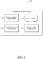
- FIG. 2is a block diagram of an embodiment of a communication system 200 that can independently provide a cellular network that is mobile.
- the communication system 200can also be referred to as a mobile cellular network (MCN) communication system.
- the communication system 200includes a radio access component 250 , which can be used to send/receive wireless communication to/from the communication system 200 , a control and data component 252 , and a data store 254 .
- the communication system 200can include fewer or more components as desired and as described in greater detail in U.S. application Ser. Nos. 13/972,112 and 14/264,297, entitled Mobile Cellular Networks and Mobile Cellular Network Backhaul, respectively, each of which is incorporated by reference herein in its entirety.
- the communication system 200can include and/or can communicate with an antenna, satellite dish, and the like, to receive data from UE or other endpoints, other communication systems, satellites, and the like.
- the communication system 200can communicate with multiple eNodeBs, base stations, or the like, to increase its coverage area.
- the received/transmitted datacan all be in the form of IP data packets.
- One or more communication systemscan be deployed in areas where cellular networks are not available and each communication system can independently provide a self-contained cellular network that is portable during operation for devices in respective coverage areas.
- multiple communication systemscan be networked together to create a network of communication systems, also referred to herein as a NOM, as described in greater detail in U.S. application Ser. Nos. 13/972,112 and 14/264,297, incorporated by reference.
- the different communication systems within the NOM or between NOMscan communicate with each other via a backhaul using a variety of communication technologies, including satellite communication, microwave or radio wave communication, OFDM, WiMAX, LTE, etc., as described in greater detail in U.S. application Ser. Nos.
- each of the components of the communication system 200can include an identifier, such as an IP address, MAC address, etc.
- the networkin some embodiments a MCN
- the networkcan include one or more network identifiers, such as access point names, etc.
- different types of datacan be associated with different access point names. For example, voice-over-IP (VOIP) data can be associated with one access point of the communication system, Internet data can be associated with a different access point of the communication system, etc.
- VOIPvoice-over-IP
- video data, video data, audio data, file transfer data, text or short message service (SMS) data, multimedia or multimedia message service (MMS) data, etc.can each be assigned to a different APN, or grouped together in any combination on the same APN, as desired.
- the use of different APNscan be based on network policy, such as, but not limited to, treatment of different types of packets or data, treatment of different users.
- the use of different APNscan be based on billing systems (e.g., the ability to charge for different types of data), carrier grade redundancy (e.g., making data paths for some type of data more resilient than others, such as to make voice data more reliable than Internet data).
- Packets sent over the networkcan use the network identifiers of the communication system 200 to identify the communication system that is to process the packet and/or that can access a particular destination, etc.
- the communication system 200can function in an independent mode where communication with other communication systems or a backhaul communication is limited or non-existent.
- the first communication systemupon receiving a packet of data, can refer to a look-up table stored in a data storage device to determine whether a destination identifier of the packet is within its covered area. If the destination is within the covered area (non-limiting examples: an endpoint within the covered area, a component of the communication system, etc.), the communication system can transmit the data to the destination.
- the datacan include any one or more types of communications, including, but not limited to, user plane data (non-limiting examples: voice data, video data, e-mail, SMS data, picture data, files, requests for information, etc.) or control plane data. If the first communication system determines that the destination is not within its covered area, the first communication system can transmit a message to the source that communication with the destination is not available, etc.
- the communication systemcan also function in a networked mode such that communication with a destination is available even if the destination is not located within the communication system's covered area.
- the destinationmay be accessible via the Internet (non-limiting examples: via satellite or wired communication), microwave communication, LTE backhaul, or other form of backhaul technology, etc.
- multiple communication systems 200can be related together.
- multiple communication systemswhen in the networked mode can be associated together and/or networked together as described in greater detail in U.S. application Ser. No. 13/972,112, previously incorporated herein by reference in its entirety.
- the communication systemscan have different functionality depending on their relationship with the other communication systems. For example, as described in greater in U.S. application Ser. Nos. 13/972,112 and 14/264,297, incorporated herein by reference, when related together, one of the communication systems can be designated as a host communication system or Master Device, while the remaining communication systems can be designated as client communication systems, relay communication systems, and/or Secondary Devices.
- a UEcan move from the covered area of a first communication system to the covered area of a second communication system without disrupting the service of the UE.
- the first and second communication systemcan effectuate a handover that updates which communication system is the local MCN for the UE.
- the UEcan establish a first cellular communication link with the first communication system and terminate a second cellular communication link with the second communication system.
- Any communication systems to which the UE is registeredcan similarly update its routing table and any session identifiers in order to continue providing a communication pathway or link for the UE.
- control and data component 252can be implemented using one or more computer processors, FPGAs, microcontrollers, etc., and can perform the various operations of the communication system 200 .
- the control and data component 252can include a packet data network gateway (PGW), serving gateway (SGW), mobility management entity (MME), and policy and charging rules function (PCRF).
- PGWpacket data network gateway
- SGWserving gateway
- MMEmobility management entity
- PCRFpolicy and charging rules function
- the PGWcan provide the IP traffic interface between the UE and external IP networks. Together with the SGW, the PGW can route all IP packets between the UE and the external IP network.
- the PGWcan perform policy enforcement, packet filtering for each UE, charging support, packet screening, quality of service, EPS network support, static policy, IPv4 packet data network (PDN), and network address support.
- the PGWcan also provide support for mobility between 3GPP and non-3GPP technologies such as WiMAX and 3GPP2, etc.
- the SGWcan route and forward user data packets, and work with the PGW to handle user data between the radio access component and external IP networks.
- the SGWcan route the user data from the UE to the PGW or from the PGW to the UE, and provide support during inter-communication system handovers.
- the SGWcan terminate the downlink data path and trigger paging when downlink data arrives for the UE.
- the SGWcan also manage and store UE contexts, e.g. parameters of the IP bearer service, network internal routing information.
- the MMEcan be responsible for attaching and detaching a UE from the communication system 200 and authenticating the user (by interacting with the home subscriber server (HSS), described in greater detail below). Furthermore, the MME can be responsible for choosing the SGW and PGW for a UE, and can manage PDN connections. In addition, the MME can be responsible for UE tracking and paging procedures including retransmissions.
- HSShome subscriber server
- the PCRFcan provide network control regarding the service data flow detection, gating, quality of service, and flow based charging towards a Policy and Charging Enforcement Function (PCEF) contained in the PGW.
- PCEFPolicy and Charging Enforcement Function
- the PCRFcan contain a database holding dynamic policy and charging rules information for the communication system.
- control and data component 252can perform the attachment and detachment of UE, authentication procedures, gateway selection, managing PDN connections, UE tracking and paging, etc.
- the control and data component 252can also handle the user data between the radio access component and an external IP network, packet routing and forwarding, handover functions between communication systems, packet buffering initiation of network triggered service request procedures, quality of service policy enforcement, static policy, subscriber location management, subscriber data, and the like.
- control and data component 252can perform additional procedures as described in greater detail in U.S. application Ser. No. 13/972,112, previously incorporated herein by reference.
- the data store 254can include data regarding the UE in communication with the communication system 200 and within the coverage area corresponding to the communication system 200 , such as UE location, authentication keys, etc.
- the data store 254can include a home subscriber server (HSS).
- HSShome subscriber server
- the data store 254can include information regarding other communication systems that are registered with the communication system 200 .
- the HSScan include subscription information for all UE (including client communications systems that are registered as UE) associated with the communication system, such as all the UE located within the covered area of a communication system and/or the UE located within the covered area of related or associated communication systems.
- the HSScan store, for example, authentication parameters, security keys, and subscription information for UE within the communication system or associated with the communication system.
- the HSScan include subscriber location information and be involved with subscriber data handling, authentication procedures, etc.
- the data store 254can further include data identifying other related communication systems.
- the data identifying the other related communication systemscan be used to communicate with the other communication systems.
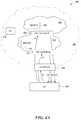
- FIG. 3is a diagram of an embodiment of multiple communication systems 302 , 304 , 306 , 308 and their corresponding coverage areas 312 , 314 , 316 , and 318 , respectively.
- the communication systems 302 , 304 , 306 , 308in some embodiments, can be networked together to form a network of communication systems (NOM).
- NOMnetwork of communication systems
- some of the coverage areas 312 , 314 , 316are managed by communication systems 302 , 304 , 306 that are on the ground.
- the communication systemscan be located on a moving object, such as an airplane, drone 320 , automobile, ship, boat, or other vehicle.
- the coverage areascan move with the communication system.
- the coverage areas 312 , 314 , 316are adjacent to each other, while coverage area 318 is not adjacent to any of the other coverage areas.
- the communication systems 302 , 304 , 306 , and 308can communicate with each other via any one, or any combination, of satellite communication via satellite 305 , microwave, or radio wave communication, OFDM, WiMAX, LTE backhaul, etc.
- the illustrated embodiment of FIG. 3further includes the UE 1 located within coverage area 316 , the UE 2 located within coverage area 314 , and the UE 3 located within overlapping coverage areas 312 and 316 and moving towards communication system 306 .
- the UE 3is located within overlapping coverage areas 312 and 316 that correspond to communication systems 302 and 306 , respectively. Similar to gateway 104 of FIG. 1 , communication systems 302 , 306 can enable the UE 3 to access a source network (for example, associated with communication systems 302 ) and a destination network (associated with communication systems 302 ), respectively, as well as one or more other UE, other devices, private networks (non-limiting example: a highly secure network), the Internet, etc.
- a source networkfor example, associated with communication systems 302
- a destination networkassociated with communication systems 302
- private networksnon-limiting example: a highly secure network
- the Internetetc.
- the UE 3has accessed a highly secure network via communication system 302 and having entered the coverage area 316 , the UE 3 received one or more network parameters from the communication system 306 .
- the UE 3can identify a network (sometimes referred to as a destination network) associated with the communication system 306 by comparing the received parameters to one or more stored network parameters.
- the UE 3can access stored network parameters that are associated with various networks with which it is configured to connect, and compare the stored network parameters with the network parameters received from the communication system 306 . Based on the comparison, the UE 3 can identify the network associated with the received network parameter, the network to which the UE 3 is connected, or determine whether the UE 3 is configured to join the network associated with the communication system 306 .
- the UE 3can identify additional network information associated with the destination network, such as, private network information associated with private networks accessible via the destination network, and endpoint information associated with endpoints that are accessible via the destination network (non-limiting examples: in the destination network or in the private networks associated with the destination network, etc.) prior to, after, or while it identifies other network information (non-limiting examples: network identifiers).
- additional network information associated with the destination networksuch as, private network information associated with private networks accessible via the destination network, and endpoint information associated with endpoints that are accessible via the destination network (non-limiting examples: in the destination network or in the private networks associated with the destination network, etc.) prior to, after, or while it identifies other network information (non-limiting examples: network identifiers).
- the UE 3uses the received network parameters (non-limiting examples: APN, RAT, PLMN, etc.), the UE 3 joins the destination network.
- the received network parametersindicate that the UE 3 has joined the destination network (non-limiting examples: IP address, point-of-presence, etc.).
- the UE 3joins the destination network based on a detected network change.
- the detected network changecan, for example, be associated with an established connection with communication system 302 (non-limiting examples: a weakening or lost connection), a connection to communication system 306 (non-limiting examples: a new or strengthening signal), movement by the UE 3 , receipt of a network parameter from communication system 306 , etc.
- the detected network changecan correspond to a user input or a user's request to disconnect from communication system 302 or communicate with a different communication system, such as communication system 306 .
- the detected network changeincludes one or more of a change of IP address of the UE 3 , a change in point-of-presence (e.g., an access point to the Internet) of the UE 3 , a change of IP address of a network gateway, a change in APN, a change in network identifier, a change in SSID, a change in session ID, a change in RAT, a change in PLMN, a change of tunnel or TUN interface (e.g., a change of interface on an operating system), a network change system event or a change in some other network parameter.
- a change of IP address of the UE 3a change in point-of-presence (e.g., an access point to the Internet) of the UE 3 , a change of IP address of a network gateway, a change in
- the UE 3uses network parameters broadcast by the gateway, to initiate a procedure, such as a random-access procedure, to establish a low-level connection to the communication system 306 .
- a proceduresuch as an RRC connection
- the UE 3can access the stored private network information to execute one or more applications and/or provide the proper credentials to join the private network(s) available via the destination network.
- the UE 3in order to access a particular private network, provides multiple private network credentials and/or establishes multiple VPN tunnels.
- the VPN tunnelsare layered such that one VPN tunnel is established within another VPN tunnel.
- the UE 3can access a highly secure network by establishing a first virtual private network (VPN) tunnel to a first private network and establishing a second VPN tunnel (non-limiting example: nested within the first VPN tunnel) to the highly secure network.
- VPNvirtual private network
- the UE 3can maintain permissions which enable the UE 3 to automatically access one or more networks, access one or more private networks available via the associated networks, and/or access or use one or more endpoints available via the associated networks or private networks. Thus, the UE 3 will have the proper credentials to access one or more networks, even if the networks are private or highly secure.
- FIG. 4Ais a data flow diagram illustrative of an embodiment of communications between various devices within the environment 400 to establish one or more virtual private network (VPN) tunnels associated with a communication system.
- VPNvirtual private network
- the environment 400can include fewer or more components as desired and/or be configured differently than what is shown in FIG. 4A .
- the environment 400can omit the first PN gateway 422 , the first PN 424 , the second PN gateway 426 , and/or the second PN 428 .
- the UE 402communicates with the network gateway 404 .
- the UE 402requests access to network 406 , for example, by providing an access point to, or requesting an access point from, the network gateway 404 .
- the UE 402can request or gain access to the network 406 or any other network in a variety of ways (non-limiting example: the UE 402 can provide an access point identifier, or other network identifier, to the network gateway 404 ).
- the network gateway 404can validate the UE 402 for the network 406 .
- the UE 402communicates with the network gateway 404 once a network corresponding to the network gateway 404 is detected and without user interaction with the UE 402 . In certain embodiments, the UE 402 initiates communication based at least in part on user interaction in which the user requests access to the network 406 and/or data or a computing device that is accessible via the network 406 . In some cases, the UE 402 initiates communication based at least in part on a detected network change, as described herein.
- the UE 402terminates one or more VPN tunnels that were used by the UE 402 to access one or more network associated with another communication system.
- the UE 402can detect a network change, and, in response, can terminate a VPN tunnel.
- the UE 402may have been accessing one or more networks (non-limiting example: a private network) associated with the other communication system using one or more VPN tunnels.
- the UE 402may have been using one or more network identifiers associated with one or more networks corresponding to the another communication system.
- the UE 402can delete and/or discontinue the use of the network identifiers associated with one or more networks corresponding to the another communication system.
- the UE 402can cease communication with a network gateway associated with the other communication system.
- the one or more VPN tunnelsare terminated automatically or without action from the UE 402 (non-limiting example, one or more VPN tunnels to one or more private networks associated with the other communication system are automatically terminated or lost when the UE 402 moves outside a coverage area of the second communication system).
- the one or more VPN tunnelsmay have been automatically terminated, yet the UE 402 can confirm that the VPN tunnels are terminated prior to establishing any new VPN tunnels.
- the UE 402receives one or more network parameters from the network gateway 404 .
- the network parameterincludes a network identifier, such as an IP address, APN, and/or other identifier.
- a network identifiersuch as an IP address, APN, and/or other identifier.
- network parameterscan be used and/or sent to the UE 402 , such as, but not limited to, a RAT, SSID, PLMN, etc.
- the UE 402can compare the received network parameter with stored network information, such as stored network parameters, to identify the network 406 that is associated with the received network parameter and the network gateway 404 .
- the UE 402can compare the received network parameter with the various network parameters stored thereon to identify a match. And from the match, the UE 402 can identify the network associated with the received network parameter. Further, the UE 402 can use the received network parameter to determine if the UE 402 is configured to join the network 406 associated with the gateway 404 . If the UE 402 is configured to join the network 406 , it can join the network (if it has not done so already) and proceed to step 3 . If not, the UE 402 can discontinue the process of joining the network 406 or discontinue communications with the gateway 404 .
- stored network informationsuch as stored network parameters
- the UE 404can also determine or receive location data from the gateway 404 .
- the UE 402can compare the location data to stored network information (non-limiting examples: stored location information associated with one or more gateways) to determine if the location of the gateway 404 (or its own location) corresponds to a location identified by the stored network information. If the location of the gateway 404 does not correspond to the location data of the stored network information, the UE 402 can discontinue the process of joining the network 406 or discontinue communications with the gateway 404 .
- location datacan be used by the UE 402 to verify that the UE 402 is configured to join a particular network and/or communicate with a particular gateway. Based on a determination that the received network parameter corresponds to a stored network parameter, the UE 402 can identify the network 406 and network information associated with the network 406 .
- the UE 402can ( 3 ) use the stored network information associated with the network 406 to communicate with a first PN gateway 422 and establish a first VPN tunnel (non-limiting example: using a VPN client) to the corresponding first PN 424 .
- the network informationcan include computer-executable applications that initiate establishing the first VPN tunnel to the first PN 424 , as well as the various credentials, certificates, identifiers, and passwords to establish the VPN tunnel to the first PN 424 .
- the UE 402can access one or more endpoints within the network 406 , such as the UE 430 or other endpoints (non-limiting examples: UE, devices, servers, networks, etc., within the network 406 ).
- the UE 402can automatically communicate with the first PN gateway 422 based at least in part on receipt of the network parameter and joining the network 406 without any further user interaction with the UE 402 .
- the UE 402communicates with the first PN gateway 422 based at least in part on a user initiating an application or other computer-executable instructions, or on the user interacting with the UE 402 to request access to the first PN gateway 422 , the network 406 , a private network 424 , 428 available via the network 406 and/or a computing device 432 , 434 available via the network 406 .
- a usermay request to communicate with device 434 .
- the UE 402 or an application on the UE 402establishes a dynamic layering of authentication software (e.g., VPN clients) that the UE can utilize to direct traffic from one VPN tunnel through another VPN tunnel.
- the UE 402can establish a first VPN tunnel using a first VPN client and can establish a second VPN tunnel using a second VPN client.
- the UE 402can control the second VPN client so that the second VPN client routes its outgoing traffic through the first VPN client.
- the second VPN tunnelcan be established within the first VPN tunnel (also referred to herein as nesting).
- the UE 402can provide the first PN gateway 422 with private network information, such as one or more credentials stored on the UE 402 (non-limiting examples: identifiers, certifications, username, password, IKE key type, IKE identify, IKE version requirement, split tunnel definition, suite B encryption settings, phase 1 settings, Diffie-Helman groups supported, or other cryptographic keys, CA certificate information, user certificate information, authentication data, etc.).
- the UE 402can provide first PN gateway 422 with private network information, such as authentication data (non-limiting examples: a MAC address, SIM card information, serial number, certifications, certificate authority information, user certificate information, username, password, password-derived keys, hashes, salted hashes of unique device properties and/or user passwords, credentials, etc.), in order to establish the first VPN tunnel with the first PN gateway 422 .
- the first PN gateway 422can use the private network information, such as credentials or authentication data, to authenticate and validate the UE 402 for the first PN 424 .
- the UE 402receives a first PN identifier (e.g., through a VPN tunnel) associated with the first PN 424 .
- the first PN gateway 422can provide the UE 402 with a first PN identifier for the first PN 424 based, at least in part, on authenticating the UE 402 for the first PN 424 .
- the first PN identifierincludes an IP address.
- IP addressIP address
- the UE 402can access one or more endpoints within the first PN 424 , such as the second PN gateway 426 or other endpoints (non-limiting examples: UE, devices, servers, networks, etc., within the PN 124 ).
- endpoints within the first PN 424such as the second PN gateway 426 or other endpoints (non-limiting examples: UE, devices, servers, networks, etc., within the PN 124 ).
- the UE 402uses the first PN identifier from the first PN gateway 422 to establish a second VPN tunnel (non-limiting examples: using a second VPN client, using a first and second VPN client) with the second PN gateway 426 .
- the second VPN tunnelis established within the first VPN tunnel.
- the second VPN tunnelcan be established similar to the first VPN tunnel, in that the UE 402 can provide the second PN gateway 426 with at least a portion of the private network information and the second PN gateway 426 can use the received data to validate the UE 402 for the second PN 428 .
- the UE 402can provide second PN authentication data, as described herein, in order to establish the second VPN tunnel with the second PN gateway 426 .
- the UE 402can dynamically layer authentication software (e.g., VPN clients) such that one VPN client routes its traffic through another VPN client.
- the UE 402can automatically communicate with the second PN gateway 426 based at least in part on receipt of the first PN identifier without any further user interaction with the UE 402 .
- the UE 402communicates with the second PN gateway 426 based at least in part on a user initiating an application or other computer-executable instructions or on the user interacting with the UE 402 to request access to the second PN gateway 426 , the network 406 , a private network 424 , 428 available via the network 406 and/or a computing device 432 , 434 available via the network 406 .
- the second PN gateway 426can ( 6 ) communicate a second PN identifier associated with the second PN 428 to the UE 402 .
- the UE 402can communicate with one or more endpoints within the second PN 428 .
- the UE 402can maintain at least three network identifiers: a network identifier for communications with endpoints within the network 406 , a first PN identifier for communications with endpoints within the first PN 424 , and a second PN identifier for communications with endpoints within the second PN 428 .
- the UE 402may not send communications to the network gateway 404 prior to receiving a network parameter from the network gateway 404 .
- the network gateway 404can broadcast network parameters at regular intervals, which can be received by any UE located within the coverage area of the network gateway 404 .
- operations or eventscan be performed concurrently, e.g., the UE 402 can concurrently establish a first VPN tunnel to the first PN and a second VPN tunnel to the second PN.
- the network gateway 404can provide the UE 402 with a network identifier at the same time that it forwards that UE's 402 identification data to the first PN gateway 422 , etc.
- any one or any combination of the activities described abovecan occur automatically and/or without user input.
- the UE 402can detect the network gateway 404 , establish a VPN tunnel to the PNs 424 , 428 , access stored network information, and/or shutdown a VPN tunnel to the first PN 424 or the second VPN 428 , and/or cease use or delete the PN identifier without user input.
- FIG. 4Billustrates an environment 400 b that provides additional details regarding the setup of VPN clients, according to some embodiments.
- the UE 402 of FIG. 4Bwill be described in the context of the data flow diagram 400 of FIG. 4A , it should be noted that FIG. 4B provides an example of some, but not necessarily all, UE environments and therefore should not be construed as limiting.
- the UE 402communicates with the network gateway 404 to request access to network 406 .
- the UE 402receives one or more network parameters from the network gateway 404 .
- the UE 402can use the received network parameter to determine if the UE 402 is configured to join the network 406 associated with the gateway 404 . If the UE 402 is configured to join the network 406 , it can join the network (if it has not done so already) and proceed to step 3 .
- the UE 402can use stored network information associated with the network 406 to communicate with a first PN gateway 422 and establish a first VPN tunnel to the first PN 424 .
- the UE 402can use a VPN manager 444 to route stored network information associated with the PN 424 to a first VPN client 440 .
- the first VPN client 440can establish the first VPN tunnel by encrypting and/or encapsulating (e.g., with an IP header containing routing information) the stored network information.
- the stored network information associated with the PN 424is then transmitted by the UE 402 through gateway 404 , to PN gateway 422 .
- the PN gateway 422can then decrypt and/or un-encapsulate the data, and authenticate and validate the UE 402 for the first PN 424 .
- the UE 402receives a first PN identifier through the first VPN tunnel.
- the PN gateway 422transmits the first PN identifier through the first VPN tunnel.
- the first VPN clientcan decrypt and un-encapsulate the data.
- the UE 402can use stored network information associated with PN 428 to communicate with a second PN gateway 426 and establish a second VPN tunnel to the second PN 428 .
- the UE 402can use the VPN manager 444 to route the stored network information associated with the PN 428 to the second VPN client 442 .
- the second VPN client 442can establish a second VPN tunnel by encrypting and encapsulating the stored network information.
- the UE 402can then use the VPN manager to direct or control the second VPN client such that it routes its data to the first VPN client 440 .
- the first VPN client 440can further encrypt and encapsulate the stored network information.
- the stored network information associated with the PN 428is then transmitted by the UE 402 through gateway 404 and PN gateway 422 , to PN gateway 426 .
- the PN gateway 422can decrypt and un-encapsulate a first layer of decryption and encapsulation associated with the first VPN client
- the PN gateway 426can decrypt and un-encapsulate a second layer of decryption and encapsulation associated with the second VPN client.
- the second PN gateway 426can then authenticate and validate the UE 402 for the second PN 428 .
- the UE 402receives a second PN identifier through the first and second VPN tunnels.
- the PN gateway 426transmits the second PN identifier to the UE 402 , through the first PN gateway 422 .
- the second PN gateway 426 and the first PN gateway 422can each add a layer of encryption and encapsulation to the data.
- the UE 402can receive the data with two layers of encryption.
- the first VPN client 440can decrypt and un-encapsulate a first layer of data corresponding to the first PN gateway 422 .
- the UE 402using the VPN manager 444 , can then direct or control the first VPN client 440 to route the data to the second VPN client.
- the second VPN client 442can decrypt and un-encapsulate a second layer of data corresponding to the second PN gateway 426 .
- the UE 402can then use the second PN identifier associated with the second PN 428 to communicate with one or more endpoints within the second PN 428 .
- the VPN client 442can route all outgoing traffic through VPN client 440 . Similarly, all inbound traffic can be first routed through VPN client 440 and then through VPN client 442 . In this way, outbound traffic can be dual encrypted layered and dual encrypted and layered inbound traffic can be correctly processed in order to access the underlying data.
- the VPN manager 444controls a plurality of VPN clients including the first VPN client 440 and the second VPN client 442 .
- the VPN manager 444can shuffle the order to the VPN clients such that nested VPN tunnels can be established in various orders.
- the VPN manager 444can route the data from the first or second VPN client 440 , 442 such that the first VPN tunnel is nested with the second VPN tunnel or the second VPN tunnel is nested with the first VPN tunnel.
- one or more of the VPN clientshave different and distinct cryptographic stacks and key stores.
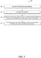
- FIG. 5is a flow diagram illustrative of an embodiment of a routine implemented by a UE for establishing one or more virtual private network tunnels within a network.
- routine 500may be implemented by one or many computing devices/components, such as the UE, an communication system or one of its components, another computing device, etc. Accordingly, routine 500 has been logically associated as being generally performed by the UE, and thus the following illustrative embodiments should not be construed as limiting.
- the UEreceives network parameters from a network gateway.
- the network parameterscan be included in broadcast messages, such as master information blocks or system information blocks, broadcast from a communication system or network gateway, or be included as part of the UE joining a particular network.
- the network parameterscan include one or more IP addresses, access point identifiers, APNs, network names, network identifiers, SSIDs, session IDs, RATs, PLMN IDs, radio access component or eNodeB identifiers, device identifiers, device names, or other network parameters that are associated with a particular network.
- the UEidentifies a network associated with the received network parameter(s).
- the UEcan store network information, such as stored network parameters, corresponding to a plurality of networks or private networks to which the UE can join.
- the UEcan use the stored network information to identify the network associated with the received network parameter(s) and/or determine whether the UE is configured to join the network associated with the received network parameter by comparing the stored network information (non-limiting example: stored network parameters) to the received network parameter. For example, the UE can determine that it is configured to join a particular network, and identify the particular network, based on a determination that the received network parameter corresponds to or matches a stored network parameter.
- Example network parametersinclude, but are not limited to IP address, APN, SSID, RAT, PLMN, point-of-presence, etc.
- the UEcan identify the network based on one or more IP addresses or a change in IP address. For example, the UE can compare a received IP address with a group of IP addresses stored on the UE as network information and associated with different networks or gateway. Based on the comparison and identifying a matching IP address from the group of stored IP addresses, the UE can identify the networks or gateways that correspond to the received IP address.
- the UEcan identify the network based on an APN or a change in APN. For example, the UE can compare a received APN with a group of APN stored on the UE as network information and associated with different networks or gateway. Based on the comparison and identifying a matching APN from the group of stored APNs, the UE can identify the networks or gateways that correspond to the received APN.
- the UEcan identify the network based on a SSID or a change in SSID. For example, the UE can compare a received SSID with a group of SSID stored on the UE as network information and associated with different networks or gateway. Based on the comparison and identifying a matching SSID from the group of stored SSIDs, the UE can identify the networks or gateways that correspond to the received SSID.
- the UEcan identify the network based on a RAT or a change in RAT. For example, the UE can compare a received RAT with a group of RATs stored on the UE as network information and associated with different networks or gateway. Based on the comparison and identifying a matching RAT from the group of stored RATs, the UE can identify the networks or gateways that correspond to the received RAT
- the UEcan identify the network based on a PLMN or a change in PLMN. For example, the UE can compare a received PLMN with a group of PLMNs stored on the UE as network information and associated with different networks or gateway. Based on the comparison and identifying a matching PLMN from the group of stored PLMNs, the UE can identify the networks or gateways that correspond to the received PLMN.
- the UEcan identify the network based on a point-of-presence or a change in point-of-presence. For example, the UE can compare a received point-of-presence with a group of points of presence stored on the UE as network information and associated with different networks or gateway. Based on the comparison, the UE can identify the networks or gateways that correspond to the received point-of-presence.
- the UEcan identify the network based on one or more received network parameters or a change in network parameters. For example, the UE can compare a received network parameter with a group of network parameters stored on the UE as network information and associated with different networks or gateway. Based on the comparison, the UE can identify the networks or gateways that correspond to the received network parameter.
- the UEcan identify the network based on a change in session ID. For example, the UE can compare a received session ID with a group of session IDs stored on the UE as network information and associated with different networks or gateway. Based on the comparison, the UE can identify the networks or gateways that correspond to the received session ID.
- the UEcan use multiple network parameters to identify a network.
- the UEcan include or can receive geographic information (non-limiting examples: spatial or geographic data) that includes, for example, an actual or expected location of the UE, one or more communication systems, associated coverage areas, etc.
- the UEcan compare its location at the time that it received the network parameter with an expected geographic area.
- the expected geographic areacan be based on the expected location of the UE, the expected location of the communication system associated with the network parameter, or the expected location of the coverage area associated with the communication system. If, for example, the UE determines that it is outside of the expected geographic area, the UE can provide an error message indicating that it is not in the appropriate geographic area.
- the UEcan proceed to use one or more other network parameters to identify the network. In some embodiments, the UE can determine it is moving such that it will eventually exit or enter a specific coverage area corresponding to a specific network. In some embodiments, the UE can identify the specific network that it will enter.
- the UEidentifies private network information or endpoint information such as private network credentials for accessing one or more virtual private networks via the identified network.
- the UEstores private network information of private networks that are accessible via different networks. Accordingly, based on the identity of the identified network, the UE can identify the private network which it can join via the identified network.
- the private network informationcan include, but is not limited to, data and/or programs used by the UE to access one or more private networks accessible via the identified network and/or one or more devices accessible via the identified network or private networks.
- the UEcommunicates with the identified network gateway once the identified network is identified and without user interaction with the UE. In certain embodiments, the UE initiates communication based at least in part on user interaction in which the user requests access to the identified destination network and/or data or a computing device that is accessible via the identified destination network. In some cases, the UE initiates communication based at least in part on a detected network change, as described herein.
- the UEestablishes at least one VPN tunnel via the identified network.
- the UEuses a network identifier received as part of joining the identified network to communicate with at least one PN gateway and establish at least one VPN tunnel.
- the UEcan automatically communicate with the PN gateway based at least in part on receipt of the network identifier without any further user interaction with the UE.
- the UEcommunicates with the PN gateway based at least in part on a user initiating an application or other computer-executable instructions or on the user interacting with the UE to request access to the PN gateway, the identified network, and/or a computing device available via the identified network.
- the UEcan provide the PN gateway with private network information, such as private network credentials (non-limiting examples: identifiers, certifications, username, password, IKE key type, IKE identify, IKE version requirement, split tunnel definition, suite B encryption settings, phase 1 settings, Diffie-Helman groups supported, or other cryptographic keys, CA certificate information, user certificate information, authentication data, etc.) and/or stored authentication data (non-limiting examples: a MAC address, SIM card information, serial number, certifications, certificate authority information, user certificate information, username, password, password-derived keys, hashes, salted hashes of unique device properties and/or user passwords, credentials, etc.) in order to establish the VPN tunnel with the PN gateway.
- the PN gatewaycan use the private network credentials or authentication data to authenticate and validate the UE for the PN.
- the UEreceives a PN identifier associated with a PN.
- a PN gatewayprovides the UE with a PN identifier for the PN based, at least in part, on authenticating the UE for the PN.
- the PN identifierincludes an IP address.
- the UEcan access one or more endpoints within the PN, such as a second PN gateway or other endpoints (non-limiting examples: UE, devices, servers, networks, etc., within the PN).
- the UEestablishes another VPN tunnel associated with another PN using the PN identifier.
- the UEcan use the PN identifier to communicate with a second PN gateway to establish a second VPN tunnel.
- the UEcan establish the second VPN tunnel similar to the manner in which the UE establishes the first VPN tunnel.
- the UEcan establish a nested VPN tunnel, as described herein.
- routine 500can be performed in a different sequence, can be added, merged, or left out altogether (non-limiting example: not all described operations or events are necessary for the practice of the routine 500 ).
- operations or eventscan be performed concurrently, e.g., through multi-threaded processing, interrupt processing, or multiple processors or processor cores or on other parallel architectures, rather than sequentially.
- the routine 500can include joining the identified or destination network.
- the UEcan join the destination network prior to or after receiving the network parameters.
- the UEcan use the received network parameters to join the destination network, and in certain embodiments, the UE receives the network parameters upon joining the destination network. Further, in certain cases, the UE joins the destination network prior to, concurrently with, or after identifying the destination network and/or identifying the private network information or endpoint information.
- the routine 500can include terminating one or more VPN tunnels to one or more private networks associated with a communication system.
- the UEcan delete and/or discontinue the use of network identifiers associated with one or more private networks associated with the communication system.
- the UEcan cease communication with a network gateway associated with the communication system.
- one or more VPN tunnelsare terminated automatically or without action from the UE (non-limiting example, one or more VPN tunnels to one or more private networks associated with a second MCN system are automatically terminated or lost when the UE moves outside a coverage area of the second MCN system).
- the one or more VPNmay be automatically terminated, yet the UE confirms that the VPN tunnels are terminated prior to establishing a new VPN tunnel.
- FIG. 6is a flow diagram illustrative of an embodiment of a routine 600 implemented by a UE for establishing one or more virtual private network tunnels within a network.
- routine 600may be implemented by one or many computing devices/components, such as the UE, an communication system or one of its components, another computing device, etc. Accordingly, routine 600 has been logically associated as being generally performed by the UE, and thus the following illustrative embodiments should not be construed as limiting.
- a network changecan include a receipt of network parameters.
- the UEmay detect a change of IP address of the wireless mobile communication device, a change in point-of-presence of the wireless mobile communication device, a change of IP address of another network gateway, a change in APN, a change in network identifier, a change in SSID, a change in session ID, a change in RAT, a change in PLMN, a loss of signal to another network, a gain of signal to another network.
- a usermay trigger a network change (non-limiting examples: user initiating an application or other computer-executable instructions, user requesting a new network, etc.).
- a network changenon-limiting examples: user initiating an application or other computer-executable instructions, user requesting a new network, etc.
- a userprovides input to the UE, requesting the UE change networks.
- the UEidentifies a network and identifies private network information for accessing one or more VPNs via the identified network, respectively, similar to what is described herein with reference to blocks 504 , 506 of FIG. 5 .
- the private network informationcan be stored on the UE and the UE can access the private network information from memory.
- the UEcommunicates with a first PN gateway to establish a first VPN tunnel to a corresponding first PN.
- the UEcan automatically communicate with the first PN gateway based at least in part on receipt of a network identifier without any further user interaction with the UE.
- the UEcommunicates with the first PN gateway based at least in part on a user initiating an application or other computer-executable instructions or on the user interacting with the UE to request access to the first PN gateway, the identified network, and/or a computing device available via the identified network.
- the UEcan provide the first PN gateway with identified private network information such as private network credentials and/or authentication data, described previously, in order to establish the first VPN tunnel with the first PN gateway.
- the first PN gatewaycan use the private network information to authenticate and validate the UE for the first PN.
- the UE 402receives a first PN identifier associated with the first PN.
- the first PN gatewayprovides the UE with a first PN identifier for the first PN based, at least in part, on authenticating the UE for the first PN.
- the first PN identifierincludes an IP address.
- the UEcan access one or more endpoints within the first PN, such as a second PN gateway or other endpoints (non-limiting examples: UE, devices, servers, networks, etc., within the first PN).
- the first PN identifiercan be the same type of identifier as the first network identifier or different.
- the UEcan access the various endpoints within the first PN.
- the UEcommunicates with a second PN gateway to establish a second VPN tunnel to a second PN associated with the identified network. For example, using at least the first PN identifier, the UE can communicate with the second PN gateway to establish the second VPN tunnel to the second PN. As described previously, the UE can establish the second VPN tunnel by providing the second PN gateway with one or more credentials, identifiers, certifications, etc. The second PN gateway can use the data to authenticate and validate the UE for the second PN.
- the second PN gatewaycan provide the UE with (and the UE can receive) a second PN identifier.
- the second PN identifiercan be the same type of identifier as the first network identifier, the first PN identifier, or different. Using the second PN identifier, the UE can access the various endpoints within the second PN.
- routine 600can be performed in a different sequence, can be added, merged, or left out altogether (non-limiting example: not all described operations or events are necessary for the practice of the routine 600 ). In certain embodiments, operations or events can be performed concurrently, e.g., through multi-threaded processing, interrupt processing, or multiple processors or processor cores or on other parallel architectures, rather than sequentially.
- routine 600can further include joining a destination network and/or terminating one or more VPN tunnels associated with a source network.
- the backhaul access componentcan be implemented as a standalone device and can communicate with an communication system and/or a component of a network to control access to the backhaul.
- the backhaul access componentcan be configured to communicate with a base station or a core component of a cellular network, such as, but not limited to, a component of the evolved packet core (EPC) of a long-term evolution (LTE) system, etc., or other type of wireless network.
- EPCevolved packet core
- LTElong-term evolution
- the backhaul access componentcan cause the corresponding component to perform some or all of the functions described herein with respect to the communication system.
- Conditional languagesuch as, among others, “can,” “could,” “might,” or “may,” unless specifically stated otherwise, or otherwise understood within the context as used, is generally intended to convey that certain embodiments include, while other embodiments do not include, certain features, elements, and/or steps. Thus, such conditional language is not generally intended to imply that features, elements and/or steps are in any way required for one or more embodiments or that one or more embodiments necessarily include logic for deciding, with or without user input or prompting, whether these features, elements and/or steps are included or are to be performed in any particular embodiment.
- eachin addition to having its ordinary meaning, can mean any subset of a set of elements to which the term “each” is applied.
- the words “comprise,” “comprising,” and the likeare to be construed in an inclusive sense, as opposed to an exclusive or exhaustive sense; that is to say, in the sense of “including, but not limited to.”
- the terms “connected,” “coupled,” or any variant thereofmeans any connection or coupling, either direct or indirect, between two or more elements; the coupling or connection between the elements can be physical, logical, or a combination thereof.
- the words “herein,” “above,” “below,” and words of similar importwhen used in this application, refer to this application as a whole and not to any particular portions of this application.
- words in the above Detailed Description using the singular or plural numbermay also include the plural or singular number respectively.
- the word “or” in reference to a list of two or more itemscovers all of the following interpretations of the word: any one of the items in the list, all of the items in the list, and any combination of the items in the list.
- the term “and/or” in reference to a list of two or more itemscovers all of the following interpretations of the word: any one of the items in the list, all of the items in the list, and any combination of the items in the list.
- operations, acts, events, or functions of any of the algorithms described hereincan be performed in a different sequence, can be added, merged, or left out altogether (non-limiting example: not all are necessary for the practice of the algorithms).
- operations, acts, functions, or eventscan be performed concurrently, e.g., through multi-threaded processing, interrupt processing, or multiple processors or processor cores or on other parallel architectures, rather than sequentially.
- processor devicecan be a microprocessor, but in the alternative, the processor device can be a controller, microcontroller, or combinations of the same, or the like.
- a processor devicecan include electrical circuitry configured to process computer-executable instructions.
- a processor deviceincludes an FPGA or other programmable device that performs logic operations without processing computer-executable instructions.
- a processor devicecan also be implemented as a combination of computing devices, e.g., a combination of a DSP and a microprocessor, a plurality of microprocessors, one or more microprocessors in conjunction with a DSP core, or any other such configuration.
- a processor devicemay also include primarily analog components. For example, some or all of the signal processing algorithms described herein may be implemented in analog circuitry or mixed analog and digital circuitry.
- a computing environmentcan include any type of computer system, including, but not limited to, a computer system based on a microprocessor, a mainframe computer, a digital signal processor, a portable computing device, a device controller, or a computational engine within an appliance, to name a few.
- a software modulecan reside in RAM memory, flash memory, ROM memory, EPROM memory, EEPROM memory, registers, hard disk, a removable disk, a CD-ROM, or any other form of a non-transitory computer-readable storage medium.
- An exemplary storage mediumcan be coupled to the processor device such that the processor device can read information from, and write information to, the storage medium.
- the storage mediumcan be integral to the processor device.
- the processor device and the storage mediumcan reside in an ASIC.
- the ASICcan reside in a user terminal.
- the processor device and the storage mediumcan reside as discrete components in a user terminal.
- processing of the various components of the illustrated systemscan be distributed across multiple machines, networks, and other computing resources.
- two or more components of a systemcan be combined into fewer components.
- Various components of the illustrated systemscan be implemented in one or more virtual machines, rather than in dedicated computer hardware systems and/or computing devices.
- Virtualization technologiesallow a single physical computing device to host one or more instances of a virtual machine, which virtual machine instance appears to a user as an independent computing device.
- the host computing devicecan create, maintain, delete, or otherwise manage virtual machines instances in a dynamic manner.
- userscan request computing resources, including single computing devices or a configuration of networked computing devices, and be provided with virtual machine instances that provide the requested computing resources.
- An instance of a virtual machinemay be configured to provide specific functionality.
- a virtual machine instancemay be associated with different combinations of software applications and operating systems or operating system configurations to enable a virtual machine to provide different desired functionalities, or to provide similar functionalities more efficiently.
- Disjunctive languagesuch as the phrase “at least one of X, Y, or Z,” unless specifically stated otherwise, is otherwise understood with the context as used in general to present that an item, term, etc., may be either X, Y, or Z, or any combination thereof (non-limiting examples: X, Y, and/or Z). Thus, such disjunctive language is not generally intended to, and should not, imply that certain embodiments require at least one of X, at least one of Y, or at least one of Z to each be present.
- a device configured toare intended to include one or more recited devices. Such one or more recited devices can also be collectively configured to carry out the stated recitations.
- a processor configured to carry out recitations A, B and Ccan include a first processor configured to carry out recitation A working in conjunction with a second processor configured to carry out recitations B and C.
Landscapes
- Engineering & Computer Science (AREA)
- Computer Networks & Wireless Communication (AREA)
- Signal Processing (AREA)
- Computer Security & Cryptography (AREA)
- Mobile Radio Communication Systems (AREA)
Abstract
Description
Claims (18)
Priority Applications (2)
| Application Number | Priority Date | Filing Date | Title |
|---|---|---|---|
| US15/625,735US10873891B2 (en) | 2016-07-06 | 2017-06-16 | Secure network rollover |
| US17/101,418US11671893B2 (en) | 2016-07-06 | 2020-11-23 | Secure network rollover |
Applications Claiming Priority (2)
| Application Number | Priority Date | Filing Date | Title |
|---|---|---|---|
| US201662358990P | 2016-07-06 | 2016-07-06 | |
| US15/625,735US10873891B2 (en) | 2016-07-06 | 2017-06-16 | Secure network rollover |
Related Child Applications (1)
| Application Number | Title | Priority Date | Filing Date |
|---|---|---|---|
| US17/101,418ContinuationUS11671893B2 (en) | 2016-07-06 | 2020-11-23 | Secure network rollover |
Publications (2)
| Publication Number | Publication Date |
|---|---|
| US20180014340A1 US20180014340A1 (en) | 2018-01-11 |
| US10873891B2true US10873891B2 (en) | 2020-12-22 |
Family
ID=60911320
Family Applications (2)
| Application Number | Title | Priority Date | Filing Date |
|---|---|---|---|
| US15/625,735ActiveUS10873891B2 (en) | 2016-07-06 | 2017-06-16 | Secure network rollover |
| US17/101,418Active2037-09-03US11671893B2 (en) | 2016-07-06 | 2020-11-23 | Secure network rollover |
Family Applications After (1)
| Application Number | Title | Priority Date | Filing Date |
|---|---|---|---|
| US17/101,418Active2037-09-03US11671893B2 (en) | 2016-07-06 | 2020-11-23 | Secure network rollover |
Country Status (1)
| Country | Link |
|---|---|
| US (2) | US10873891B2 (en) |
Cited By (10)
| Publication number | Priority date | Publication date | Assignee | Title |
|---|---|---|---|---|
| US11134425B2 (en) | 2016-07-07 | 2021-09-28 | Oceus Networks, Llc | Network backhaul access |
| US11184840B2 (en) | 2017-03-31 | 2021-11-23 | Oceus Networks, Llc | Targeted user equipment-base station communication link |
| US11246031B2 (en) | 2018-08-15 | 2022-02-08 | Oceus Networks, Llc | Disguising UE communications in a cellular network |
| US11252128B2 (en) | 2013-04-29 | 2022-02-15 | Oceus Networks, Llc | Mobile cellular network backhaul |
| US20220346051A1 (en)* | 2019-11-08 | 2022-10-27 | Apostolis Salkintzis | Registering with a mobile network through another mobile network |
| US11582671B2 (en) | 2012-08-24 | 2023-02-14 | Oceus Networks, Llc | Mobile cellular networks |
| US11588790B2 (en) | 2016-07-07 | 2023-02-21 | Oceus Networks, Llc | Secure network enrollment |
| US11671893B2 (en) | 2016-07-06 | 2023-06-06 | Oceus Networks, Llc | Secure network rollover |
| US11743740B2 (en) | 2012-08-24 | 2023-08-29 | Oceus Networks, Llc | Mobile cellular networks |
| US12301543B2 (en) | 2022-05-31 | 2025-05-13 | Microsoft Technology Licensing, Llc | Multiple virtual private network active connection management |
Families Citing this family (14)
| Publication number | Priority date | Publication date | Assignee | Title |
|---|---|---|---|---|
| CN111918361B (en)* | 2018-06-22 | 2022-02-01 | 维沃移动通信有限公司 | Processing method, terminal and network element |
| US11792599B2 (en)* | 2018-06-29 | 2023-10-17 | Apple Inc. | Device support for scalable neutral host and private LTE/5G network discovery, and device mobility |
| CN110971641B (en) | 2018-09-30 | 2022-04-19 | 维沃移动通信有限公司 | A kind of network service control method and communication device |
| CN111917893B (en)* | 2019-05-10 | 2022-07-12 | 华为云计算技术有限公司 | Virtual private cloud and cloud data center communication, configuration method and related device |
| US11876798B2 (en)* | 2019-05-20 | 2024-01-16 | Citrix Systems, Inc. | Virtual delivery appliance and system with remote authentication and related methods |
| CN110662197A (en)* | 2019-09-02 | 2020-01-07 | 京信通信系统(中国)有限公司 | Parameter configuration method, device, communication device and storage medium |
| US11272554B2 (en)* | 2020-02-26 | 2022-03-08 | At&T Iniellectual Property I, L.P. | Facilitation of radio access network multi-access 5G or other next generation network |
| US12041449B2 (en)* | 2020-04-10 | 2024-07-16 | Qualcomm Incorporated | Method and apparatus for verifying mobile device communications |
| US11882129B2 (en)* | 2020-07-15 | 2024-01-23 | Fenix Group, Inc. | Self-contained robotic units for providing mobile network services and intelligent perimeter |
| US20220210130A1 (en)* | 2020-12-31 | 2022-06-30 | Netflow, UAB | Method and apparatus for maintaining a resilient vpn connection |
| LU102626B1 (en)* | 2021-03-01 | 2022-09-01 | Wenzl Ehm Alexander | Process for the transmission of encrypted messages |
| US12088558B2 (en)* | 2021-06-29 | 2024-09-10 | Charter Communications Operating, Llc | Method and apparatus for automatically switching between virtual private networks |
| CN116319162B (en)* | 2022-09-08 | 2023-12-12 | 惠州市海葵信息技术有限公司 | Communication connection method, control device and user terminal equipment based on double-layer tunnel |
| US11962503B1 (en)* | 2023-01-30 | 2024-04-16 | DittoLive Incorporated | Edge synchronization platform |
Citations (98)
| Publication number | Priority date | Publication date | Assignee | Title |
|---|---|---|---|---|
| US5309503A (en) | 1991-12-06 | 1994-05-03 | Motorola, Inc. | Dynamic channel assignment in a communication system |
| US5768501A (en) | 1996-05-28 | 1998-06-16 | Cabletron Systems | Method and apparatus for inter-domain alarm correlation |
| EP1401229A1 (en) | 2002-09-23 | 2004-03-24 | Telefonaktiebolaget LM Ericsson (publ) | Method and apparatus for faciliting handovers for a group of mobile radios |
| US20040259555A1 (en) | 2003-04-23 | 2004-12-23 | Rappaport Theodore S. | System and method for predicting network performance and position location using multiple table lookups |
| US6842462B1 (en) | 1998-12-18 | 2005-01-11 | Lucent Technologies Inc. | Wireless access of packet based networks |
| EP1553734A1 (en) | 2002-10-18 | 2005-07-13 | Matsushita Electric Industrial Co., Ltd. | Method and device for roaming-connection in global network |
| US6965816B2 (en) | 2001-10-01 | 2005-11-15 | Kline & Walker, Llc | PFN/TRAC system FAA upgrades for accountable remote and robotics control to stop the unauthorized use of aircraft and to improve equipment management and public safety in transportation |
| US20060015745A1 (en) | 2004-07-13 | 2006-01-19 | Sony Corporation | Information processing system, information processing device, and program |
| US20060098661A1 (en) | 2004-11-08 | 2006-05-11 | Lemko Corporation | System, method and device for providing communications using a distributed mobile architecture |
| US7072657B2 (en)* | 2002-04-11 | 2006-07-04 | Ntt Docomo, Inc. | Method and associated apparatus for pre-authentication, preestablished virtual private network in heterogeneous access networks |
| US20060178153A1 (en) | 2005-02-08 | 2006-08-10 | Tenny Nathan E | Method and apparatus for allocating resources in a multicast/broadcast communications system |
| US20060192651A1 (en) | 2003-03-22 | 2006-08-31 | You-Young Lee | Data transmit system and transmit methods by using n-dimensional information |
| US20060234747A1 (en) | 2005-04-13 | 2006-10-19 | Lemko, Corporation | System, method, and device for providing communications using a distributed mobile architecture |
| US20060234774A1 (en) | 2005-04-13 | 2006-10-19 | Lemko, Corporation | System, method, and device for providing communications using a distributed mobile architecture |
| US20070049267A1 (en) | 2005-08-15 | 2007-03-01 | Incode Telecom Group, Inc. | Embedded wireless location validation benchmarking systems and methods |
| WO2007044880A2 (en) | 2005-10-07 | 2007-04-19 | Pacific Star Communications, Inc. | Self-contianed portable broadband communications system |
| US20070202847A1 (en) | 2006-02-24 | 2007-08-30 | Lemko, Corporation | System, method, and device for providing communications using a distributed mobile architecture |
| US20070232267A1 (en) | 2006-03-30 | 2007-10-04 | Lemko, Corporation | System, method, and device for providing communications using a distributed mobile architecture |
| US20070253359A1 (en) | 2006-04-26 | 2007-11-01 | Goran Hall | Network initiated mobility management for mobile terminals |
| US20070264930A1 (en) | 2004-12-03 | 2007-11-15 | Orangefrance | Telecommunication System and Method for Operating a Mobile Telephone on Board An Aircraft or Ship, Land Station and Base Station Adapted for Said System |
| US20070287452A1 (en) | 2006-06-12 | 2007-12-13 | Lemko, Corporation | Roaming mobile subscriber registration in a distributed mobile architecture |
| US20080005380A1 (en) | 2006-02-21 | 2008-01-03 | Pacific Star Communications, Inc. | Integrated configuration and management of hardware devices |
| US7317717B2 (en)* | 2004-04-26 | 2008-01-08 | Sprint Communications Company L.P. | Integrated wireline and wireless end-to-end virtual private networking |
| US20080095070A1 (en)* | 2005-12-05 | 2008-04-24 | Chan Tat K | Accessing an IP multimedia subsystem via a wireless local area network |
| US20080108378A1 (en) | 2006-10-27 | 2008-05-08 | Rohde & Schwarz Gmbh & Co. Kg | Flexible network architecture with user group support |
| US7389534B1 (en)* | 2003-06-27 | 2008-06-17 | Nortel Networks Ltd | Method and apparatus for establishing virtual private network tunnels in a wireless network |
| US20080146158A1 (en) | 2006-12-13 | 2008-06-19 | Lemko, Corporation | System, method, and device to control wireless communications |
| US20080181188A1 (en) | 2007-01-31 | 2008-07-31 | Abdol Hamid Aghvami | Systems and Methods for Improving Network Mobility |
| US20080268830A1 (en) | 2007-04-30 | 2008-10-30 | Ranjan Sharma | Proximity detection of coverage area boundary and display of mobile station location relative thereto |
| US20080285492A1 (en) | 2007-05-18 | 2008-11-20 | Seppo Vesterinen | System and Method for Providing Local IP Breakout Services Employing Access Point Names |
| EP2031920A1 (en) | 2007-06-29 | 2009-03-04 | Nokia Siemens Networks Oy | Method for handover data acqusition in a cellular communications network and communications network |
| GB2452796A (en) | 2007-09-14 | 2009-03-18 | Actix Ltd | Managing and optimising the performance of mobile phone networks |
| US7535861B2 (en) | 2005-10-07 | 2009-05-19 | Pacific Star Communications Inc. | Self-contained portable broadband communication system |
| US20090156213A1 (en) | 2007-10-25 | 2009-06-18 | Spinelli Vincent | Interworking gateway for mobile nodes |
| US7567822B2 (en) | 2005-10-11 | 2009-07-28 | Cisco Technology, Inc. | Automated configuration of RF WLANs via selected sensors |
| US7573713B2 (en) | 2005-09-13 | 2009-08-11 | Pacific Star Communications | High velocity air cooling for electronic equipment |
| US20090201878A1 (en) | 2007-11-19 | 2009-08-13 | Cellco Partnership D/B/A Verizon Wireless | Low latency handover between wireless communication networks using different radio access technologies |
| WO2009100736A1 (en) | 2008-02-14 | 2009-08-20 | T-Mobile International Ag | Roaming communication network |
| US20090232019A1 (en) | 2008-03-12 | 2009-09-17 | Qualcomm Incorporated | Providing multiple levels of service for wireless communication |
| WO2009127965A1 (en) | 2008-04-18 | 2009-10-22 | Telefonaktiebolaget Lm Ericsson (Publ) | Auto-configuration and discovery of portable telecommunication system |
| US20090271491A1 (en) | 2008-04-23 | 2009-10-29 | Lemko, Corporation | System and method to control wireless communications |
| US20090280853A1 (en) | 2008-05-07 | 2009-11-12 | At&T Mobility Ii Llc | Signaling-triggered power adjustment in a femto cell |
| US20090327819A1 (en) | 2008-06-27 | 2009-12-31 | Lemko, Corporation | Fault Tolerant Distributed Mobile Architecture |
| US20090325584A1 (en) | 2008-06-26 | 2009-12-31 | Lemko, Corporation | System and Method to Control Wireless Communications |
| US20100008369A1 (en) | 2008-07-14 | 2010-01-14 | Lemko, Corporation | System, Method, and Device for Routing Calls Using a Distributed Mobile Architecture |
| US20100008306A1 (en) | 2008-07-11 | 2010-01-14 | Lemko, Corporation | Oamp for distributed mobile architecture |
| US20100027448A1 (en) | 2008-06-27 | 2010-02-04 | Sanil Kumar Puthiyandyil | Method and system for supporting packet data network communications |
| US7684801B2 (en) | 2002-10-28 | 2010-03-23 | Ntt Docomo, Inc. | Control device, handover control method and mobile communication system |
| US20100075668A1 (en) | 2008-09-25 | 2010-03-25 | Lemko, Corporation | Multiple imsi connections |
| US20100105373A1 (en) | 2008-10-28 | 2010-04-29 | Qualcomm Incorporated | Location Information For Control of Mode/Technology |
| US20100190470A1 (en) | 2009-01-28 | 2010-07-29 | Gregory G. Raleigh | Roaming services network and overlay networks |
| US20100197268A1 (en) | 2009-01-28 | 2010-08-05 | Headwater Partners I Llc | Enhanced roaming services and converged carrier networks with device assisted services and a proxy |
| US20100202455A1 (en) | 2009-02-11 | 2010-08-12 | Ganapathy Sundaram | Method for secure network based route optimization in mobile networks |
| US7805372B2 (en) | 2006-02-21 | 2010-09-28 | Weiss Kenneth P | Universal secure registry |
| US7817589B2 (en) | 2006-02-21 | 2010-10-19 | Pacific Star Communications, Inc. | Self-contained portable broadband communications system |
| US20110122824A1 (en) | 2008-07-24 | 2011-05-26 | Ahmad Muhanna | Anchoring services of a mobile station attached to a first service domain at a home agent in a second service domain |
| US20110130135A1 (en) | 2009-12-01 | 2011-06-02 | Hafedh Trigui | Coverage hole detector |
| US20110176536A1 (en) | 2010-01-18 | 2011-07-21 | De Franca Lima Octavio Jose | Heirarchical protocol classification |
| US20110195743A1 (en) | 2008-09-12 | 2011-08-11 | Electronics And Telecommunications Research Institute | Method and apparatus for power management |
| US20110202589A1 (en) | 2010-02-15 | 2011-08-18 | Openwave Systems Inc. | Scripting/proxy systems, methods and circuit arrangements |
| US20110263253A1 (en) | 2004-02-26 | 2011-10-27 | Research In Motion Limited | Cellular communications system with mobile cellular device battery saving features based upon quality of service and access denial and related methods |
| US20110275364A1 (en) | 2010-05-06 | 2011-11-10 | At&T Services, Inc. | Device-driven intelligence and feedback for performance optimization and planning of a service network |
| US20110300866A1 (en) | 2010-06-04 | 2011-12-08 | Research In Motion Limited | System and method for reporting of neighbour cells in handover from gan |
| US20120051321A1 (en) | 2010-08-24 | 2012-03-01 | Clear Wireless Llc | Method for seamless ip session continuity for multi-mode mobile stations |
| US20120057568A1 (en) | 2009-03-17 | 2012-03-08 | Seau Sian Lim | Cellular wireless network and method of operation |
| US8140077B2 (en) | 2006-04-19 | 2012-03-20 | Nokia Corporation | Handover or location update for optimization for relay stations in a wireless network |
| US20120147874A1 (en) | 2008-02-06 | 2012-06-14 | Cellco Partnership D/B/A Verizon Wireless | Route optimization using network enforced, mobile implemented policy |
| US20120224474A1 (en) | 2008-05-15 | 2012-09-06 | Beser Nurettin Burcak | Systems and methods for distributed data routing in a wireless network |
| US20120224566A1 (en) | 2011-03-04 | 2012-09-06 | Rogers Communications Inc. | Method and device for re-using ipsec tunnel in customer premises equipment |
| US20120269167A1 (en) | 2009-10-29 | 2012-10-25 | Panasonic Corporation | Enhanced attachment procedure for attaching a ue to a 3gpp access network |
| US20120276866A1 (en) | 2009-10-01 | 2012-11-01 | At&T Mobility Ii, Llc. | Systems and Methods for Identifying a Geographical Area in a Commercial Mobile Alert Service Message |
| US20130003697A1 (en) | 2011-07-01 | 2013-01-03 | Interdigital Patent Holdings, Inc. | Method and apparatus for supporting local ip access and selected ip traffic offload |
| US20130029708A1 (en) | 2011-06-24 | 2013-01-31 | Vodafone Ip Licensing Limited | Telecommunication networks |
| US20130028097A1 (en) | 2011-07-29 | 2013-01-31 | Intellectual Ventures Holding 81 Llc | Communications terminal and method |
| US8374124B2 (en) | 2007-02-12 | 2013-02-12 | Alcatel Lucent | Method and apparatus for providing IP mobility and IP routing in ad hoc wireless networks |
| US8503336B2 (en) | 2000-09-25 | 2013-08-06 | Wireless Valley Communications, Inc | System and method for design, tracking, measurement, prediction and optimization of data communication networks |
| US8626210B2 (en) | 2010-11-15 | 2014-01-07 | At&T Intellectual Property I, L.P. | Methods, systems, and products for security systems |
| WO2014031597A1 (en) | 2012-08-24 | 2014-02-27 | Oceus Networks Inc. | Mobile cellular networks |
| WO2014031689A1 (en) | 2012-08-24 | 2014-02-27 | Oceus Networks Inc. | Mobile cellular networks |
| US8811992B2 (en) | 2009-02-24 | 2014-08-19 | Eden Rock Communications, Llc | Systems and methods for assigning regional wireless communications handovers utilizing ancillary cell feedback |
| US8824969B2 (en) | 2010-05-13 | 2014-09-02 | Ntt Docomo, Inc. | Radio base station and mobile communication method |
| WO2014179235A1 (en) | 2013-04-29 | 2014-11-06 | Oceus Networks Inc. | Mobile cellular network backhaul |
| US9055163B1 (en) | 2014-12-01 | 2015-06-09 | Oceus Networks, Inc. | Methods of operating wireless parameter-sensing nodes and remote host |
| US20150181492A1 (en) | 2013-12-20 | 2015-06-25 | Andreas Schmidt | Base station and method for early handover using uplink channel characteristics |
| US20150304282A1 (en)* | 2014-04-21 | 2015-10-22 | Cisco Technology, Inc. | Nested Independent Virtual Private Networks With Shared Rekey And Consistency Services |
| US20150319774A1 (en) | 2014-05-05 | 2015-11-05 | Blackberry Limited | Identifying a subframe containing information relating to an uplink grant |
| US20150358959A1 (en) | 2012-03-02 | 2015-12-10 | Qualcomm Incorporated | Managing perfomance of a wireless network using backhaul metrics |
| US9264241B2 (en) | 2013-01-09 | 2016-02-16 | Tabletop Media Llc | Secure wireless network-based activation for table-side information and point-of-sale devices |
| US9338093B2 (en)* | 2010-12-17 | 2016-05-10 | Verizon Patent And Licensing Inc. | Mobile phone docking station VPNs |
| US9444801B2 (en) | 2010-11-24 | 2016-09-13 | Alcatel Lucent | Method, device and system for verifying communication sessions |
| US20160359738A1 (en)* | 2015-06-04 | 2016-12-08 | Cisco Technology, Inc. | Tunnel-in-tunnel source address correction |
| US20160365882A1 (en) | 2015-06-10 | 2016-12-15 | Samsung Electronics Co., Ltd. | Broadcast signal receiving apparatus and multi-layer printed circuit board |
| US9686238B1 (en) | 2016-07-07 | 2017-06-20 | Oceus Networks Inc. | Secure network enrollment |
| US9924427B2 (en) | 2016-07-07 | 2018-03-20 | Oceus Networks Inc. | Network backhaul access |
| US20180192264A1 (en) | 2016-12-30 | 2018-07-05 | T-Mobile Usa, Inc. | Open Access Points for Emergency Calls |
| US20180288687A1 (en) | 2017-03-31 | 2018-10-04 | Oceus Networks Inc. | Targeted user equipment-base station communication link |
| US20190053145A1 (en) | 2016-02-18 | 2019-02-14 | Kyocera Corporation | Radio communication device and method for controlling same |
| US20200059785A1 (en) | 2018-08-15 | 2020-02-20 | Oceus Networks Inc. | Disguising ue communications in a cellular network |
Family Cites Families (35)
| Publication number | Priority date | Publication date | Assignee | Title |
|---|---|---|---|---|
| US6026277A (en) | 1997-10-20 | 2000-02-15 | Gavrilovich; Charles D. | Mobile communication system with moving base station |
| US6334059B1 (en) | 1999-01-08 | 2001-12-25 | Trueposition, Inc. | Modified transmission method for improving accuracy for e-911 calls |
| US7246045B1 (en) | 2000-08-04 | 2007-07-17 | Wireless Valley Communication, Inc. | System and method for efficiently visualizing and comparing communication network system performance |
| EP1438826B1 (en) | 2001-10-24 | 2007-10-10 | Siemens Aktiengesellschaft | Method and device for authenticated access to a station on local data networks, in particular radio data networks |
| US20040259554A1 (en) | 2003-04-23 | 2004-12-23 | Rappaport Theodore S. | System and method for ray tracing using reception surfaces |
| WO2006015427A1 (en) | 2004-08-11 | 2006-02-16 | National Ict Australia Limited | Quality of service seeker |
| US7353034B2 (en) | 2005-04-04 | 2008-04-01 | X One, Inc. | Location sharing and tracking using mobile phones or other wireless devices |
| US7912471B2 (en) | 2006-01-04 | 2011-03-22 | Wireless Technology Solutions Llc | Initial connection establishment in a wireless communication system |
| US20090298514A1 (en) | 2006-09-14 | 2009-12-03 | Shah Ullah | Real world behavior measurement using identifiers specific to mobile devices |
| US20100260109A1 (en) | 2009-04-10 | 2010-10-14 | Qualcomm Incorporated | Optimized inter-access point packet routing for ip relay nodes |
| CN102301818A (en) | 2009-04-21 | 2011-12-28 | 华为技术有限公司 | Method, relay node and system for processing data in relay link |
| CN101998511B (en) | 2009-08-26 | 2013-04-24 | 华为技术有限公司 | Header compression method and device under network relay scene |
| KR101580153B1 (en) | 2009-09-24 | 2016-01-04 | 삼성전자주식회사 | Apparatus and method for multiple hop relay communication in broadband wireless communication system |
| EP2524450A1 (en) | 2010-01-13 | 2012-11-21 | Telefonaktiebolaget L M Ericsson (PUBL) | Distributed relay for multi-hop communication network |
| US9749880B2 (en) | 2010-06-30 | 2017-08-29 | Verizon Patent And Licensing Inc. | Base station failover using neighboring base stations as relays |
| WO2013085852A1 (en) | 2011-12-05 | 2013-06-13 | Jasper Wireless, Inc. | Global platform for managing subscriber identity modules |
| WO2013119156A1 (en) | 2012-02-09 | 2013-08-15 | Telefonaktiebolaget L M Ericsson (Publ) | Full and partial resource access in ran sharing |
| WO2014007687A1 (en) | 2012-07-02 | 2014-01-09 | Telefonaktiebolaget L M Ericsson (Publ) | Method and radio access node for incorporating a moving cell in a wireless communication network |
| US9414273B2 (en) | 2012-08-08 | 2016-08-09 | At&T Intellectual Property I, L.P. | Inbound handover for macrocell-to-femtocell call transfer |
| US8867418B2 (en) | 2013-02-17 | 2014-10-21 | Parallel Wireless, Inc. | Methods of incorporating an ad hoc cellular network into a fixed cellular network |
| EP3174261B1 (en) | 2014-08-22 | 2020-07-08 | Huawei Technologies Co., Ltd. | Multilink fusion method, server and client |
| US20160157281A1 (en) | 2014-12-02 | 2016-06-02 | Time Warner Cable Enterprises Llc | Consolidation of management communications in a network environment |
| US11178558B2 (en) | 2015-05-22 | 2021-11-16 | Parallel Wireless, Inc. | Wireless backhaul resiliency |
| US10797992B2 (en)* | 2015-07-07 | 2020-10-06 | Cisco Technology, Inc. | Intelligent wide area network (IWAN) |
| US10762156B2 (en) | 2015-07-07 | 2020-09-01 | Yext, Inc. | Suppressing duplicate listings on multiple search engine web sites from a single source system triggered by a user |
| US10965494B2 (en)* | 2015-10-01 | 2021-03-30 | International Business Machines Corporation | Intelligent multi-channel VPN orchestration |
| US10257167B1 (en)* | 2016-06-21 | 2019-04-09 | Amazon Technologies, Inc. | Intelligent virtual private network (VPN) client configured to manage common VPN sessions with distributed VPN service |
| US10873891B2 (en) | 2016-07-06 | 2020-12-22 | Oceus Networks, Llc | Secure network rollover |
| CN109479221B (en) | 2016-07-13 | 2021-02-12 | 华为技术有限公司 | Communication method, network equipment and terminal equipment |
| US10397840B2 (en) | 2016-11-15 | 2019-08-27 | At&T Intellectual Property I, L.P. | Method and apparatus for communication device handover |
| US10979904B2 (en) | 2017-05-08 | 2021-04-13 | Lg Electronics Inc. | Method for securing connection identifier of user equipment in wireless communication system and apparatus therefor |
| US10524116B2 (en) | 2017-06-27 | 2019-12-31 | Ibasis, Inc. | Internet of things services architecture |
| US20190320358A1 (en) | 2018-04-17 | 2019-10-17 | Qualcomm Incorporated | User equipment power optimization in millimeter wave access networks |
| US11184869B2 (en) | 2018-06-26 | 2021-11-23 | Qualcomm Incorporated | Timing alignment timer in a wireless communication network |
| US11202237B2 (en) | 2018-07-24 | 2021-12-14 | Mediatek Inc. | Method for preventing an inter-rat change from being triggered and communications apparatus utilizing the same |
- 2017
- 2017-06-16USUS15/625,735patent/US10873891B2/enactiveActive
- 2020
- 2020-11-23USUS17/101,418patent/US11671893B2/enactiveActive
Patent Citations (165)
| Publication number | Priority date | Publication date | Assignee | Title |
|---|---|---|---|---|
| US5309503A (en) | 1991-12-06 | 1994-05-03 | Motorola, Inc. | Dynamic channel assignment in a communication system |
| US5768501A (en) | 1996-05-28 | 1998-06-16 | Cabletron Systems | Method and apparatus for inter-domain alarm correlation |
| US20010013107A1 (en) | 1996-05-28 | 2001-08-09 | Lundy Lewis | Method and apparatus for inter-domain alarm correlation |
| US6842462B1 (en) | 1998-12-18 | 2005-01-11 | Lucent Technologies Inc. | Wireless access of packet based networks |
| US8503336B2 (en) | 2000-09-25 | 2013-08-06 | Wireless Valley Communications, Inc | System and method for design, tracking, measurement, prediction and optimization of data communication networks |
| US6965816B2 (en) | 2001-10-01 | 2005-11-15 | Kline & Walker, Llc | PFN/TRAC system FAA upgrades for accountable remote and robotics control to stop the unauthorized use of aircraft and to improve equipment management and public safety in transportation |
| US7072657B2 (en)* | 2002-04-11 | 2006-07-04 | Ntt Docomo, Inc. | Method and associated apparatus for pre-authentication, preestablished virtual private network in heterogeneous access networks |
| EP1401229A1 (en) | 2002-09-23 | 2004-03-24 | Telefonaktiebolaget LM Ericsson (publ) | Method and apparatus for faciliting handovers for a group of mobile radios |
| EP1553734A1 (en) | 2002-10-18 | 2005-07-13 | Matsushita Electric Industrial Co., Ltd. | Method and device for roaming-connection in global network |
| US7684801B2 (en) | 2002-10-28 | 2010-03-23 | Ntt Docomo, Inc. | Control device, handover control method and mobile communication system |
| US20060192651A1 (en) | 2003-03-22 | 2006-08-31 | You-Young Lee | Data transmit system and transmit methods by using n-dimensional information |
| US20040259555A1 (en) | 2003-04-23 | 2004-12-23 | Rappaport Theodore S. | System and method for predicting network performance and position location using multiple table lookups |
| US7389534B1 (en)* | 2003-06-27 | 2008-06-17 | Nortel Networks Ltd | Method and apparatus for establishing virtual private network tunnels in a wireless network |
| US20110263253A1 (en) | 2004-02-26 | 2011-10-27 | Research In Motion Limited | Cellular communications system with mobile cellular device battery saving features based upon quality of service and access denial and related methods |
| US7317717B2 (en)* | 2004-04-26 | 2008-01-08 | Sprint Communications Company L.P. | Integrated wireline and wireless end-to-end virtual private networking |
| US20060015745A1 (en) | 2004-07-13 | 2006-01-19 | Sony Corporation | Information processing system, information processing device, and program |
| US8780804B2 (en) | 2004-11-08 | 2014-07-15 | Lemko Corporation | Providing communications using a distributed mobile architecture |
| US7539158B2 (en) | 2004-11-08 | 2009-05-26 | Lemko Corporation | System, method and device for providing communications using a distributed mobile architecture |
| US8089920B2 (en) | 2004-11-08 | 2012-01-03 | Lemko Corporation | Communications using a distributed mobile architecture |
| US20090205023A1 (en) | 2004-11-08 | 2009-08-13 | Lemko Corporation | Providing communications using a distributed mobile architecture |
| US20120106454A1 (en) | 2004-11-08 | 2012-05-03 | Lemko Corporation | Providing communications using a distributed mobile architecture |
| US20060098661A1 (en) | 2004-11-08 | 2006-05-11 | Lemko Corporation | System, method and device for providing communications using a distributed mobile architecture |
| US20070264930A1 (en) | 2004-12-03 | 2007-11-15 | Orangefrance | Telecommunication System and Method for Operating a Mobile Telephone on Board An Aircraft or Ship, Land Station and Base Station Adapted for Said System |
| US20060178153A1 (en) | 2005-02-08 | 2006-08-10 | Tenny Nathan E | Method and apparatus for allocating resources in a multicast/broadcast communications system |
| US8036158B2 (en) | 2005-04-13 | 2011-10-11 | Lemko Corporation | System, method, and device for providing communications using a distributed mobile architecture |
| US20090227235A1 (en) | 2005-04-13 | 2009-09-10 | Lemko Corporation | Communications using a distributed mobile architecture |
| US7840230B2 (en) | 2005-04-13 | 2010-11-23 | Lemko Corporation | Communications using a distributed mobile architecture |
| US20060234747A1 (en) | 2005-04-13 | 2006-10-19 | Lemko, Corporation | System, method, and device for providing communications using a distributed mobile architecture |
| US20080039144A1 (en) | 2005-04-13 | 2008-02-14 | Lemko Corporation | System, method, and device for providing communications using a distributed mobile architecture |
| US20060234774A1 (en) | 2005-04-13 | 2006-10-19 | Lemko, Corporation | System, method, and device for providing communications using a distributed mobile architecture |
| US7548763B2 (en) | 2005-04-13 | 2009-06-16 | Lemko Corporation | System, method, and device for providing communications using a distributed mobile architecture |
| US7486967B2 (en) | 2005-04-13 | 2009-02-03 | Lemko Corporation | System, method, and device for providing communications using a distributed mobile architecture |
| US20070049267A1 (en) | 2005-08-15 | 2007-03-01 | Incode Telecom Group, Inc. | Embedded wireless location validation benchmarking systems and methods |
| US7573713B2 (en) | 2005-09-13 | 2009-08-11 | Pacific Star Communications | High velocity air cooling for electronic equipment |
| US20100260157A1 (en) | 2005-10-07 | 2010-10-14 | Pacific Star Communications, Inc. | Mobile broadband communications system, such as a deployable self-contained portable system |
| US7535861B2 (en) | 2005-10-07 | 2009-05-19 | Pacific Star Communications Inc. | Self-contained portable broadband communication system |
| WO2007044880A2 (en) | 2005-10-07 | 2007-04-19 | Pacific Star Communications, Inc. | Self-contianed portable broadband communications system |
| US8654749B2 (en) | 2005-10-07 | 2014-02-18 | Pacific Star Communications, Inc. | Mobile communications system, such as a deployable self-contained portable system |
| US7567822B2 (en) | 2005-10-11 | 2009-07-28 | Cisco Technology, Inc. | Automated configuration of RF WLANs via selected sensors |
| US20080095070A1 (en)* | 2005-12-05 | 2008-04-24 | Chan Tat K | Accessing an IP multimedia subsystem via a wireless local area network |
| US8270325B2 (en) | 2006-02-21 | 2012-09-18 | Pacific Star Communications, Inc. | Mobile broadband communications system, such as a deployable self-contained portable system |
| US7805372B2 (en) | 2006-02-21 | 2010-09-28 | Weiss Kenneth P | Universal secure registry |
| US7817589B2 (en) | 2006-02-21 | 2010-10-19 | Pacific Star Communications, Inc. | Self-contained portable broadband communications system |
| US20080005380A1 (en) | 2006-02-21 | 2008-01-03 | Pacific Star Communications, Inc. | Integrated configuration and management of hardware devices |
| US7653414B2 (en) | 2006-02-24 | 2010-01-26 | Lemko Corporation | System, method, and device for providing communications using a distributed mobile architecture |
| US20070202847A1 (en) | 2006-02-24 | 2007-08-30 | Lemko, Corporation | System, method, and device for providing communications using a distributed mobile architecture |
| US7856233B2 (en) | 2006-03-30 | 2010-12-21 | Lemko Corporation | System, method, and device for providing communications using a distributed mobile architecture |
| US20070232267A1 (en) | 2006-03-30 | 2007-10-04 | Lemko, Corporation | System, method, and device for providing communications using a distributed mobile architecture |
| US8359029B2 (en) | 2006-03-30 | 2013-01-22 | Lemko Corporation | System, method, and device for providing communications using a distributed mobile architecture |
| US8688111B2 (en) | 2006-03-30 | 2014-04-01 | Lemko Corporation | System, method, and device for providing communications using a distributed mobile architecture |
| US20110059740A1 (en) | 2006-03-30 | 2011-03-10 | Lemko Corporation | System, method, and device for providing communications using a distributed mobile architecture |
| US20130130677A1 (en) | 2006-03-30 | 2013-05-23 | Lemko Corporation | System, Method, and Device for Providing Communications Using a Distributed Mobile Architecture |
| US8140077B2 (en) | 2006-04-19 | 2012-03-20 | Nokia Corporation | Handover or location update for optimization for relay stations in a wireless network |
| US20070253359A1 (en) | 2006-04-26 | 2007-11-01 | Goran Hall | Network initiated mobility management for mobile terminals |
| US20120252444A1 (en) | 2006-06-12 | 2012-10-04 | Lemko Corporation | Roaming Mobile Subscriber Registration in a Distributed Mobile Architecture |
| US8224322B2 (en) | 2006-06-12 | 2012-07-17 | Lemko Corporation | Roaming mobile subscriber registration in a distributed mobile architecture |
| US20070287452A1 (en) | 2006-06-12 | 2007-12-13 | Lemko, Corporation | Roaming mobile subscriber registration in a distributed mobile architecture |
| US20080108378A1 (en) | 2006-10-27 | 2008-05-08 | Rohde & Schwarz Gmbh & Co. Kg | Flexible network architecture with user group support |
| US8676197B2 (en) | 2006-12-13 | 2014-03-18 | Lemko Corporation | System, method, and device to control wireless communications |
| US20080146158A1 (en) | 2006-12-13 | 2008-06-19 | Lemko, Corporation | System, method, and device to control wireless communications |
| US20140154967A1 (en) | 2006-12-13 | 2014-06-05 | Lemko Corporation | System, method, and device to control wireless communications |
| US20080181188A1 (en) | 2007-01-31 | 2008-07-31 | Abdol Hamid Aghvami | Systems and Methods for Improving Network Mobility |
| US8374124B2 (en) | 2007-02-12 | 2013-02-12 | Alcatel Lucent | Method and apparatus for providing IP mobility and IP routing in ad hoc wireless networks |
| US20080268830A1 (en) | 2007-04-30 | 2008-10-30 | Ranjan Sharma | Proximity detection of coverage area boundary and display of mobile station location relative thereto |
| US20080285492A1 (en) | 2007-05-18 | 2008-11-20 | Seppo Vesterinen | System and Method for Providing Local IP Breakout Services Employing Access Point Names |
| EP2031920A1 (en) | 2007-06-29 | 2009-03-04 | Nokia Siemens Networks Oy | Method for handover data acqusition in a cellular communications network and communications network |
| GB2452796A (en) | 2007-09-14 | 2009-03-18 | Actix Ltd | Managing and optimising the performance of mobile phone networks |
| US20090156213A1 (en) | 2007-10-25 | 2009-06-18 | Spinelli Vincent | Interworking gateway for mobile nodes |
| US20090201878A1 (en) | 2007-11-19 | 2009-08-13 | Cellco Partnership D/B/A Verizon Wireless | Low latency handover between wireless communication networks using different radio access technologies |
| US20120147874A1 (en) | 2008-02-06 | 2012-06-14 | Cellco Partnership D/B/A Verizon Wireless | Route optimization using network enforced, mobile implemented policy |
| WO2009100736A1 (en) | 2008-02-14 | 2009-08-20 | T-Mobile International Ag | Roaming communication network |
| US20090232019A1 (en) | 2008-03-12 | 2009-09-17 | Qualcomm Incorporated | Providing multiple levels of service for wireless communication |
| WO2009127965A1 (en) | 2008-04-18 | 2009-10-22 | Telefonaktiebolaget Lm Ericsson (Publ) | Auto-configuration and discovery of portable telecommunication system |
| US20120002607A1 (en) | 2008-04-23 | 2012-01-05 | Lemko Corporation | System and method to control wireless communications |
| US8046420B2 (en) | 2008-04-23 | 2011-10-25 | Lemko Corporation | System and method to control wireless communications |
| US20090271491A1 (en) | 2008-04-23 | 2009-10-29 | Lemko, Corporation | System and method to control wireless communications |
| US20090280853A1 (en) | 2008-05-07 | 2009-11-12 | At&T Mobility Ii Llc | Signaling-triggered power adjustment in a femto cell |
| US20120224474A1 (en) | 2008-05-15 | 2012-09-06 | Beser Nurettin Burcak | Systems and methods for distributed data routing in a wireless network |
| US20090325584A1 (en) | 2008-06-26 | 2009-12-31 | Lemko, Corporation | System and Method to Control Wireless Communications |
| US20130148578A1 (en) | 2008-06-26 | 2013-06-13 | Lemko Corporation | System and Method to Control Wireless Communications |
| US8340667B2 (en) | 2008-06-26 | 2012-12-25 | Lemko Corporation | System and method to control wireless communications |
| US20100027448A1 (en) | 2008-06-27 | 2010-02-04 | Sanil Kumar Puthiyandyil | Method and system for supporting packet data network communications |
| US20090327819A1 (en) | 2008-06-27 | 2009-12-31 | Lemko, Corporation | Fault Tolerant Distributed Mobile Architecture |
| US8706105B2 (en) | 2008-06-27 | 2014-04-22 | Lemko Corporation | Fault tolerant distributed mobile architecture |
| US20140173388A1 (en) | 2008-06-27 | 2014-06-19 | Lemko Corporation | Fault Tolerant Distributed Mobile Architecture |
| US20100008306A1 (en) | 2008-07-11 | 2010-01-14 | Lemko, Corporation | Oamp for distributed mobile architecture |
| US20120094659A1 (en) | 2008-07-11 | 2012-04-19 | Lemko Corporation | Oamp for distributed mobile architecture |
| US8107409B2 (en) | 2008-07-11 | 2012-01-31 | Lemko Corporation | OAMP for distributed mobile architecture |
| US20110060853A1 (en) | 2008-07-14 | 2011-03-10 | Lemko Corporation | System, method, and device for routing calls using a distributed mobile architecture |
| US7855988B2 (en) | 2008-07-14 | 2010-12-21 | Lemko Corporation | System, method, and device for routing calls using a distributed mobile architecture |
| US20100008369A1 (en) | 2008-07-14 | 2010-01-14 | Lemko, Corporation | System, Method, and Device for Routing Calls Using a Distributed Mobile Architecture |
| US20130039279A1 (en) | 2008-07-14 | 2013-02-14 | Lemko Corporation | System, Method, and Device for Routing Calls Using a Distributed Mobile Architecture |
| US8310990B2 (en) | 2008-07-14 | 2012-11-13 | Lemko Corporation | System, method, and device for routing calls using a distributed mobile architecture |
| US20110122824A1 (en) | 2008-07-24 | 2011-05-26 | Ahmad Muhanna | Anchoring services of a mobile station attached to a first service domain at a home agent in a second service domain |
| US20110195743A1 (en) | 2008-09-12 | 2011-08-11 | Electronics And Telecommunications Research Institute | Method and apparatus for power management |
| US8326286B2 (en) | 2008-09-25 | 2012-12-04 | Lemko Corporation | Multiple IMSI numbers |
| US8744435B2 (en) | 2008-09-25 | 2014-06-03 | Lemko Corporation | Multiple IMSI numbers |
| US7979066B2 (en) | 2008-09-25 | 2011-07-12 | Lemko Corporation | Multiple IMSI connections |
| US20100075668A1 (en) | 2008-09-25 | 2010-03-25 | Lemko, Corporation | Multiple imsi connections |
| US20130065583A1 (en) | 2008-09-25 | 2013-03-14 | Lemko Corporation | Multiple IMSI Numbers |
| US20110223921A1 (en) | 2008-09-25 | 2011-09-15 | Lemko Corporation | Multiple imsi numbers |
| US20100105373A1 (en) | 2008-10-28 | 2010-04-29 | Qualcomm Incorporated | Location Information For Control of Mode/Technology |
| US20100190470A1 (en) | 2009-01-28 | 2010-07-29 | Gregory G. Raleigh | Roaming services network and overlay networks |
| US20100197268A1 (en) | 2009-01-28 | 2010-08-05 | Headwater Partners I Llc | Enhanced roaming services and converged carrier networks with device assisted services and a proxy |
| US20100202455A1 (en) | 2009-02-11 | 2010-08-12 | Ganapathy Sundaram | Method for secure network based route optimization in mobile networks |
| US8811992B2 (en) | 2009-02-24 | 2014-08-19 | Eden Rock Communications, Llc | Systems and methods for assigning regional wireless communications handovers utilizing ancillary cell feedback |
| US20140315553A1 (en) | 2009-02-24 | 2014-10-23 | Eden Rock Communications, Llc | Systems and methods for assigning regional wireless communications handovers utilizing ancillary cell feedback |
| US20120057568A1 (en) | 2009-03-17 | 2012-03-08 | Seau Sian Lim | Cellular wireless network and method of operation |
| US20120276866A1 (en) | 2009-10-01 | 2012-11-01 | At&T Mobility Ii, Llc. | Systems and Methods for Identifying a Geographical Area in a Commercial Mobile Alert Service Message |
| US20120269167A1 (en) | 2009-10-29 | 2012-10-25 | Panasonic Corporation | Enhanced attachment procedure for attaching a ue to a 3gpp access network |
| US20110130135A1 (en) | 2009-12-01 | 2011-06-02 | Hafedh Trigui | Coverage hole detector |
| US20110176536A1 (en) | 2010-01-18 | 2011-07-21 | De Franca Lima Octavio Jose | Heirarchical protocol classification |
| US20110202589A1 (en) | 2010-02-15 | 2011-08-18 | Openwave Systems Inc. | Scripting/proxy systems, methods and circuit arrangements |
| US20110275364A1 (en) | 2010-05-06 | 2011-11-10 | At&T Services, Inc. | Device-driven intelligence and feedback for performance optimization and planning of a service network |
| US8824969B2 (en) | 2010-05-13 | 2014-09-02 | Ntt Docomo, Inc. | Radio base station and mobile communication method |
| US20110300866A1 (en) | 2010-06-04 | 2011-12-08 | Research In Motion Limited | System and method for reporting of neighbour cells in handover from gan |
| US20120051321A1 (en) | 2010-08-24 | 2012-03-01 | Clear Wireless Llc | Method for seamless ip session continuity for multi-mode mobile stations |
| US8626210B2 (en) | 2010-11-15 | 2014-01-07 | At&T Intellectual Property I, L.P. | Methods, systems, and products for security systems |
| US9444801B2 (en) | 2010-11-24 | 2016-09-13 | Alcatel Lucent | Method, device and system for verifying communication sessions |
| US9338093B2 (en)* | 2010-12-17 | 2016-05-10 | Verizon Patent And Licensing Inc. | Mobile phone docking station VPNs |
| US20120224566A1 (en) | 2011-03-04 | 2012-09-06 | Rogers Communications Inc. | Method and device for re-using ipsec tunnel in customer premises equipment |
| US20130029708A1 (en) | 2011-06-24 | 2013-01-31 | Vodafone Ip Licensing Limited | Telecommunication networks |
| US20130003697A1 (en) | 2011-07-01 | 2013-01-03 | Interdigital Patent Holdings, Inc. | Method and apparatus for supporting local ip access and selected ip traffic offload |
| US20130028097A1 (en) | 2011-07-29 | 2013-01-31 | Intellectual Ventures Holding 81 Llc | Communications terminal and method |
| US20150358959A1 (en) | 2012-03-02 | 2015-12-10 | Qualcomm Incorporated | Managing perfomance of a wireless network using backhaul metrics |
| US9451646B2 (en) | 2012-08-24 | 2016-09-20 | Oceus Networks Inc. | Mobile cellular networks |
| US20180376398A1 (en) | 2012-08-24 | 2018-12-27 | Oceus Networks Inc. | Mobile cellular networks |
| US9167442B2 (en) | 2012-08-24 | 2015-10-20 | Oceus Networks Inc. | Mobile cellular networks |
| US10021619B2 (en) | 2012-08-24 | 2018-07-10 | Oceus Networks Inc. | Mobile cellular networks |
| US10244405B2 (en) | 2012-08-24 | 2019-03-26 | Oceus Networks Inc. | Mobile cellular networks |
| US9198221B2 (en) | 2012-08-24 | 2015-11-24 | Oceus Networks Inc. | Mobile cellular networks |
| US20180176793A1 (en) | 2012-08-24 | 2018-06-21 | Oceus Networks Inc. | Mobile cellular networks |
| US20190289471A1 (en) | 2012-08-24 | 2019-09-19 | Oceus Networks Inc. | Mobile cellular networks |
| US20170238229A1 (en) | 2012-08-24 | 2017-08-17 | Oceus Networks Inc. | Mobile cellular networks |
| US9769674B2 (en) | 2012-08-24 | 2017-09-19 | Oceus Networks Inc. | Mobile cellular networks |
| US9445280B2 (en) | 2012-08-24 | 2016-09-13 | Oceus Networks Inc. | Mobile cellular networks |
| WO2014031689A1 (en) | 2012-08-24 | 2014-02-27 | Oceus Networks Inc. | Mobile cellular networks |
| WO2014031597A1 (en) | 2012-08-24 | 2014-02-27 | Oceus Networks Inc. | Mobile cellular networks |
| US9264241B2 (en) | 2013-01-09 | 2016-02-16 | Tabletop Media Llc | Secure wireless network-based activation for table-side information and point-of-sale devices |
| WO2014179235A1 (en) | 2013-04-29 | 2014-11-06 | Oceus Networks Inc. | Mobile cellular network backhaul |
| US20200036677A1 (en) | 2013-04-29 | 2020-01-30 | Oceus Networks Inc. | Mobile cellular network backhaul |
| US10382393B2 (en) | 2013-04-29 | 2019-08-13 | Oceus Networks Inc. | Mobile cellular network backhaul |
| US9742729B2 (en) | 2013-04-29 | 2017-08-22 | Oceus Networks Inc. | Mobile cellular network backhaul |
| US20180034771A1 (en) | 2013-04-29 | 2018-02-01 | Oceus Networks Inc. | Mobile cellular network backhaul |
| US9226192B2 (en) | 2013-04-29 | 2015-12-29 | Oceus Networks Inc. | Mobile cellular network backhaul |
| US20150181492A1 (en) | 2013-12-20 | 2015-06-25 | Andreas Schmidt | Base station and method for early handover using uplink channel characteristics |
| US20150304282A1 (en)* | 2014-04-21 | 2015-10-22 | Cisco Technology, Inc. | Nested Independent Virtual Private Networks With Shared Rekey And Consistency Services |
| US20150319774A1 (en) | 2014-05-05 | 2015-11-05 | Blackberry Limited | Identifying a subframe containing information relating to an uplink grant |
| US9055163B1 (en) | 2014-12-01 | 2015-06-09 | Oceus Networks, Inc. | Methods of operating wireless parameter-sensing nodes and remote host |
| US20160359738A1 (en)* | 2015-06-04 | 2016-12-08 | Cisco Technology, Inc. | Tunnel-in-tunnel source address correction |
| US20160365882A1 (en) | 2015-06-10 | 2016-12-15 | Samsung Electronics Co., Ltd. | Broadcast signal receiving apparatus and multi-layer printed circuit board |
| US20190053145A1 (en) | 2016-02-18 | 2019-02-14 | Kyocera Corporation | Radio communication device and method for controlling same |
| US20180013724A1 (en) | 2016-07-07 | 2018-01-11 | Oceus Networks Inc. | Secure network enrollment |
| US20180249391A1 (en) | 2016-07-07 | 2018-08-30 | Oceus Networks Inc. | Network backhaul access |
| US20180234386A1 (en) | 2016-07-07 | 2018-08-16 | Oceus Networks Inc. | Secure network enrollment |
| US9924427B2 (en) | 2016-07-07 | 2018-03-20 | Oceus Networks Inc. | Network backhaul access |
| US9912640B2 (en) | 2016-07-07 | 2018-03-06 | Oceus Networks Inc. | Secure network enrollment |
| US9686238B1 (en) | 2016-07-07 | 2017-06-20 | Oceus Networks Inc. | Secure network enrollment |
| US10602410B2 (en) | 2016-07-07 | 2020-03-24 | Oceus Networks Inc. | Network backhaul access |
| US20180192264A1 (en) | 2016-12-30 | 2018-07-05 | T-Mobile Usa, Inc. | Open Access Points for Emergency Calls |
| US20180288687A1 (en) | 2017-03-31 | 2018-10-04 | Oceus Networks Inc. | Targeted user equipment-base station communication link |
| US10172078B2 (en) | 2017-03-31 | 2019-01-01 | Oceus Networks Inc. | Targeted user equipment-base station communication link |
| US20190182758A1 (en) | 2017-03-31 | 2019-06-13 | Oceus Networks Inc. | Targeted user equipment-base station communication link |
| US10631237B2 (en) | 2017-03-31 | 2020-04-21 | Oceus Networks Inc. | Targeted user equipment-base station communication link |
| US20200059785A1 (en) | 2018-08-15 | 2020-02-20 | Oceus Networks Inc. | Disguising ue communications in a cellular network |
Non-Patent Citations (10)
| Title |
|---|
| "Digital cellular telecommunications system (Phase 2+); Universal Mobile Telecommunications System (UMTS); L TE; Interworking between the Public Land Mobile Network (PLMN) supporting packet based services and Packet Data Networks (PDN)" Technical Specification, European Telecommunication Standards Institute (ETSI), France, vol. 36PP CT3, No. V11.4.0, Apr. 1, 2013. |
| 3GPP TS 23.122 v13.4.0 (May 2016) (Year: 2016).* |
| International Search Report and Written Opinion dated Feb. 11, 2014, International Application No. PCT/US2013/055864. |
| International Search Report and Written Opinion dated Nov. 8, 2013, International Application No. PCT/US2013/055721. |
| International Search Report and Written Opinion dated Sep. 26, 2014, International Application No. PCT/US2014/035732. |
| Kaul, et al.: "On the adpatation of commercial smartphones to tactical environments", Military Communications Conference, 2011, Nov. 7, 2011, pp. 2205-2210. |
| Nystromer, "Quiclink: A Portable 3G WCDMA Cellular Service, Deployed in Minutes" Presentation, Jun. 11, 2007, pp. 1-27. |
| Press Release: Harris Corporation Introduces Tactical 3G Cellular Network-in-a-Box for Warfighters, Published Apr. 19, 2011, http://harris.com/view_ pressrelease.asp?pr_id=3230. |
| Press Release: Tecore Unveils the Mobile Industry's First 3G-4G Network in a Box (NIB), Published Feb. 14, 2011, http://www.tecore.com/newsevents/release.cfm?newsID-164. |
| Tecore Networks, the Mobile Industry's First All-In-One Network Solution Supporting WCDMA, HSPA+ and L TE, first release Feb. 14, 2011, http://www.tecore.com/solutions/TecoreNetworks-Datasheet-2G-3G-4G-NetworkI nABox.pdf. |
Cited By (15)
| Publication number | Priority date | Publication date | Assignee | Title |
|---|---|---|---|---|
| US12120533B2 (en) | 2012-08-24 | 2024-10-15 | Oceus Networks, Llc | Mobile cellular networks |
| US11743740B2 (en) | 2012-08-24 | 2023-08-29 | Oceus Networks, Llc | Mobile cellular networks |
| US11582671B2 (en) | 2012-08-24 | 2023-02-14 | Oceus Networks, Llc | Mobile cellular networks |
| US11991143B2 (en) | 2013-04-29 | 2024-05-21 | Oceus Networks, Llc | Mobile cellular network backhaul |
| US11252128B2 (en) | 2013-04-29 | 2022-02-15 | Oceus Networks, Llc | Mobile cellular network backhaul |
| US11671893B2 (en) | 2016-07-06 | 2023-06-06 | Oceus Networks, Llc | Secure network rollover |
| US11588790B2 (en) | 2016-07-07 | 2023-02-21 | Oceus Networks, Llc | Secure network enrollment |
| US11134425B2 (en) | 2016-07-07 | 2021-09-28 | Oceus Networks, Llc | Network backhaul access |
| US12167288B2 (en) | 2016-07-07 | 2024-12-10 | Oceus Networks, Llc | Network backhaul access |
| US11792721B2 (en) | 2017-03-31 | 2023-10-17 | Oceus Networks, Llc | Targeted user equipment-base station communication link |
| US11184840B2 (en) | 2017-03-31 | 2021-11-23 | Oceus Networks, Llc | Targeted user equipment-base station communication link |
| US11246031B2 (en) | 2018-08-15 | 2022-02-08 | Oceus Networks, Llc | Disguising UE communications in a cellular network |
| US20220346051A1 (en)* | 2019-11-08 | 2022-10-27 | Apostolis Salkintzis | Registering with a mobile network through another mobile network |
| US12089177B2 (en)* | 2019-11-08 | 2024-09-10 | Lenovo (Singapore) Pte. Ltd. | Registering with a mobile network through another mobile network |
| US12301543B2 (en) | 2022-05-31 | 2025-05-13 | Microsoft Technology Licensing, Llc | Multiple virtual private network active connection management |
Also Published As
| Publication number | Publication date |
|---|---|
| US11671893B2 (en) | 2023-06-06 |
| US20180014340A1 (en) | 2018-01-11 |
| US20210153093A1 (en) | 2021-05-20 |
Similar Documents
| Publication | Publication Date | Title |
|---|---|---|
| US11671893B2 (en) | Secure network rollover | |
| US11968181B2 (en) | Secure network enrollment | |
| US11729619B2 (en) | Methods and apparatus for wireless communication using a security model to support multiple connectivity and service contexts | |
| CN108029017B (en) | Ways to connect for secure wifi calling via managed public WLAN access | |
| US11792721B2 (en) | Targeted user equipment-base station communication link | |
| CN106576242B (en) | User equipment identification valid for heterogeneous networks | |
| US20160330077A1 (en) | WiFi VIRTUAL NETWORK SOLUTION | |
| US20220232377A1 (en) | Disguising ue communications in a cellular network | |
| US11889308B2 (en) | Multi-access edge computing (MEC)-key id derivation in authentication between UE and edge servers | |
| US12143814B2 (en) | MEC authentication between edge enabler client and edge configuration or enabler server based on AKMA |
Legal Events
| Date | Code | Title | Description |
|---|---|---|---|
| AS | Assignment | Owner name:OCEUS NETWORKS INC., VIRGINIA Free format text:ASSIGNMENT OF ASSIGNORS INTEREST;ASSIGNORS:HILL, CHRIS;PORTER, TERRANCE SCOTT;ROW, JAMES THOMAS, II;AND OTHERS;SIGNING DATES FROM 20170702 TO 20170816;REEL/FRAME:043334/0543 | |
| STPP | Information on status: patent application and granting procedure in general | Free format text:FINAL REJECTION MAILED | |
| STPP | Information on status: patent application and granting procedure in general | Free format text:DOCKETED NEW CASE - READY FOR EXAMINATION | |
| STPP | Information on status: patent application and granting procedure in general | Free format text:NON FINAL ACTION MAILED | |
| STPP | Information on status: patent application and granting procedure in general | Free format text:RESPONSE TO NON-FINAL OFFICE ACTION ENTERED AND FORWARDED TO EXAMINER | |
| STPP | Information on status: patent application and granting procedure in general | Free format text:NOTICE OF ALLOWANCE MAILED -- APPLICATION RECEIVED IN OFFICE OF PUBLICATIONS | |
| AS | Assignment | Owner name:OCEUS NETWORKS, LLC, VIRGINIA Free format text:ENTITY CONVERSION;ASSIGNOR:OCEUS NETWORKS INC.;REEL/FRAME:053625/0786 Effective date:20200707 | |
| STPP | Information on status: patent application and granting procedure in general | Free format text:PUBLICATIONS -- ISSUE FEE PAYMENT VERIFIED | |
| STPP | Information on status: patent application and granting procedure in general | Free format text:PUBLICATIONS -- ISSUE FEE PAYMENT VERIFIED | |
| STCF | Information on status: patent grant | Free format text:PATENTED CASE | |
| FEPP | Fee payment procedure | Free format text:MAINTENANCE FEE REMINDER MAILED (ORIGINAL EVENT CODE: REM.); ENTITY STATUS OF PATENT OWNER: LARGE ENTITY | |
| FEPP | Fee payment procedure | Free format text:SURCHARGE FOR LATE PAYMENT, LARGE ENTITY (ORIGINAL EVENT CODE: M1554); ENTITY STATUS OF PATENT OWNER: LARGE ENTITY | |
| MAFP | Maintenance fee payment | Free format text:PAYMENT OF MAINTENANCE FEE, 4TH YEAR, LARGE ENTITY (ORIGINAL EVENT CODE: M1551); ENTITY STATUS OF PATENT OWNER: LARGE ENTITY Year of fee payment:4 |