US10873757B2 - Method of encoding video data - Google Patents
Method of encoding video dataDownload PDFInfo
- Publication number
- US10873757B2 US10873757B2US16/242,546US201916242546AUS10873757B2US 10873757 B2US10873757 B2US 10873757B2US 201916242546 AUS201916242546 AUS 201916242546AUS 10873757 B2US10873757 B2US 10873757B2
- Authority
- US
- United States
- Prior art keywords
- quantization parameter
- block
- motion vector
- prediction
- unit
- Prior art date
- Legal status (The legal status is an assumption and is not a legal conclusion. Google has not performed a legal analysis and makes no representation as to the accuracy of the status listed.)
- Active
Links
- 238000000034methodMethods0.000titleclaimsabstractdescription37
- 238000013139quantizationMethods0.000claimsabstractdescription180
- 239000013598vectorSubstances0.000claimsabstractdescription77
- 208000037170Delayed Emergence from AnesthesiaDiseases0.000claimsabstractdescription30
- 230000001131transforming effectEffects0.000claimsabstract4
- 230000002123temporal effectEffects0.000claimsdescription51
- 238000000638solvent extractionMethods0.000claimsdescription26
- 238000010586diagramMethods0.000description20
- 238000012805post-processingMethods0.000description7
- 239000011159matrix materialSubstances0.000description6
- 238000004891communicationMethods0.000description2
- 230000006835compressionEffects0.000description2
- 238000007906compressionMethods0.000description2
- 101100437784Drosophila melanogaster bocks geneProteins0.000description1
- 241000023320Luma <angiosperm>Species0.000description1
- 230000000903blocking effectEffects0.000description1
- 230000007423decreaseEffects0.000description1
- 239000000284extractSubstances0.000description1
- 238000001914filtrationMethods0.000description1
- OSWPMRLSEDHDFF-UHFFFAOYSA-Nmethyl salicylateChemical compoundCOC(=O)C1=CC=CC=C1OOSWPMRLSEDHDFF-UHFFFAOYSA-N0.000description1
- 238000012986modificationMethods0.000description1
- 230000004048modificationEffects0.000description1
Images


Classifications
- H—ELECTRICITY
- H04—ELECTRIC COMMUNICATION TECHNIQUE
- H04N—PICTORIAL COMMUNICATION, e.g. TELEVISION
- H04N19/00—Methods or arrangements for coding, decoding, compressing or decompressing digital video signals
- H04N19/50—Methods or arrangements for coding, decoding, compressing or decompressing digital video signals using predictive coding
- H04N19/503—Methods or arrangements for coding, decoding, compressing or decompressing digital video signals using predictive coding involving temporal prediction
- H04N19/51—Motion estimation or motion compensation
- H04N19/513—Processing of motion vectors
- H04N19/517—Processing of motion vectors by encoding
- H04N19/52—Processing of motion vectors by encoding by predictive encoding
- H—ELECTRICITY
- H04—ELECTRIC COMMUNICATION TECHNIQUE
- H04N—PICTORIAL COMMUNICATION, e.g. TELEVISION
- H04N19/00—Methods or arrangements for coding, decoding, compressing or decompressing digital video signals
- H04N19/10—Methods or arrangements for coding, decoding, compressing or decompressing digital video signals using adaptive coding
- H04N19/102—Methods or arrangements for coding, decoding, compressing or decompressing digital video signals using adaptive coding characterised by the element, parameter or selection affected or controlled by the adaptive coding
- H04N19/119—Adaptive subdivision aspects, e.g. subdivision of a picture into rectangular or non-rectangular coding blocks
- H—ELECTRICITY
- H04—ELECTRIC COMMUNICATION TECHNIQUE
- H04N—PICTORIAL COMMUNICATION, e.g. TELEVISION
- H04N19/00—Methods or arrangements for coding, decoding, compressing or decompressing digital video signals
- H04N19/10—Methods or arrangements for coding, decoding, compressing or decompressing digital video signals using adaptive coding
- H04N19/102—Methods or arrangements for coding, decoding, compressing or decompressing digital video signals using adaptive coding characterised by the element, parameter or selection affected or controlled by the adaptive coding
- H04N19/124—Quantisation
- H—ELECTRICITY
- H04—ELECTRIC COMMUNICATION TECHNIQUE
- H04N—PICTORIAL COMMUNICATION, e.g. TELEVISION
- H04N19/00—Methods or arrangements for coding, decoding, compressing or decompressing digital video signals
- H04N19/50—Methods or arrangements for coding, decoding, compressing or decompressing digital video signals using predictive coding
- H04N19/503—Methods or arrangements for coding, decoding, compressing or decompressing digital video signals using predictive coding involving temporal prediction
- H04N19/51—Motion estimation or motion compensation
- H04N19/513—Processing of motion vectors
- H—ELECTRICITY
- H04—ELECTRIC COMMUNICATION TECHNIQUE
- H04N—PICTORIAL COMMUNICATION, e.g. TELEVISION
- H04N19/00—Methods or arrangements for coding, decoding, compressing or decompressing digital video signals
- H04N19/50—Methods or arrangements for coding, decoding, compressing or decompressing digital video signals using predictive coding
- H04N19/59—Methods or arrangements for coding, decoding, compressing or decompressing digital video signals using predictive coding involving spatial sub-sampling or interpolation, e.g. alteration of picture size or resolution
- H—ELECTRICITY
- H04—ELECTRIC COMMUNICATION TECHNIQUE
- H04N—PICTORIAL COMMUNICATION, e.g. TELEVISION
- H04N19/00—Methods or arrangements for coding, decoding, compressing or decompressing digital video signals
- H04N19/10—Methods or arrangements for coding, decoding, compressing or decompressing digital video signals using adaptive coding
- H04N19/102—Methods or arrangements for coding, decoding, compressing or decompressing digital video signals using adaptive coding characterised by the element, parameter or selection affected or controlled by the adaptive coding
- H04N19/103—Selection of coding mode or of prediction mode
- H04N19/105—Selection of the reference unit for prediction within a chosen coding or prediction mode, e.g. adaptive choice of position and number of pixels used for prediction
- H—ELECTRICITY
- H04—ELECTRIC COMMUNICATION TECHNIQUE
- H04N—PICTORIAL COMMUNICATION, e.g. TELEVISION
- H04N19/00—Methods or arrangements for coding, decoding, compressing or decompressing digital video signals
- H04N19/10—Methods or arrangements for coding, decoding, compressing or decompressing digital video signals using adaptive coding
- H04N19/102—Methods or arrangements for coding, decoding, compressing or decompressing digital video signals using adaptive coding characterised by the element, parameter or selection affected or controlled by the adaptive coding
- H04N19/117—Filters, e.g. for pre-processing or post-processing
- H—ELECTRICITY
- H04—ELECTRIC COMMUNICATION TECHNIQUE
- H04N—PICTORIAL COMMUNICATION, e.g. TELEVISION
- H04N19/00—Methods or arrangements for coding, decoding, compressing or decompressing digital video signals
- H04N19/10—Methods or arrangements for coding, decoding, compressing or decompressing digital video signals using adaptive coding
- H04N19/102—Methods or arrangements for coding, decoding, compressing or decompressing digital video signals using adaptive coding characterised by the element, parameter or selection affected or controlled by the adaptive coding
- H04N19/12—Selection from among a plurality of transforms or standards, e.g. selection between discrete cosine transform [DCT] and sub-band transform or selection between H.263 and H.264
- H04N19/122—Selection of transform size, e.g. 8x8 or 2x4x8 DCT; Selection of sub-band transforms of varying structure or type
- H—ELECTRICITY
- H04—ELECTRIC COMMUNICATION TECHNIQUE
- H04N—PICTORIAL COMMUNICATION, e.g. TELEVISION
- H04N19/00—Methods or arrangements for coding, decoding, compressing or decompressing digital video signals
- H04N19/10—Methods or arrangements for coding, decoding, compressing or decompressing digital video signals using adaptive coding
- H04N19/102—Methods or arrangements for coding, decoding, compressing or decompressing digital video signals using adaptive coding characterised by the element, parameter or selection affected or controlled by the adaptive coding
- H04N19/124—Quantisation
- H04N19/126—Details of normalisation or weighting functions, e.g. normalisation matrices or variable uniform quantisers
- H—ELECTRICITY
- H04—ELECTRIC COMMUNICATION TECHNIQUE
- H04N—PICTORIAL COMMUNICATION, e.g. TELEVISION
- H04N19/00—Methods or arrangements for coding, decoding, compressing or decompressing digital video signals
- H04N19/10—Methods or arrangements for coding, decoding, compressing or decompressing digital video signals using adaptive coding
- H04N19/102—Methods or arrangements for coding, decoding, compressing or decompressing digital video signals using adaptive coding characterised by the element, parameter or selection affected or controlled by the adaptive coding
- H04N19/129—Scanning of coding units, e.g. zig-zag scan of transform coefficients or flexible macroblock ordering [FMO]
- H—ELECTRICITY
- H04—ELECTRIC COMMUNICATION TECHNIQUE
- H04N—PICTORIAL COMMUNICATION, e.g. TELEVISION
- H04N19/00—Methods or arrangements for coding, decoding, compressing or decompressing digital video signals
- H04N19/10—Methods or arrangements for coding, decoding, compressing or decompressing digital video signals using adaptive coding
- H04N19/102—Methods or arrangements for coding, decoding, compressing or decompressing digital video signals using adaptive coding characterised by the element, parameter or selection affected or controlled by the adaptive coding
- H04N19/13—Adaptive entropy coding, e.g. adaptive variable length coding [AVLC] or context adaptive binary arithmetic coding [CABAC]
- H—ELECTRICITY
- H04—ELECTRIC COMMUNICATION TECHNIQUE
- H04N—PICTORIAL COMMUNICATION, e.g. TELEVISION
- H04N19/00—Methods or arrangements for coding, decoding, compressing or decompressing digital video signals
- H04N19/10—Methods or arrangements for coding, decoding, compressing or decompressing digital video signals using adaptive coding
- H04N19/134—Methods or arrangements for coding, decoding, compressing or decompressing digital video signals using adaptive coding characterised by the element, parameter or criterion affecting or controlling the adaptive coding
- H04N19/136—Incoming video signal characteristics or properties
- H04N19/137—Motion inside a coding unit, e.g. average field, frame or block difference
- H04N19/139—Analysis of motion vectors, e.g. their magnitude, direction, variance or reliability
- H—ELECTRICITY
- H04—ELECTRIC COMMUNICATION TECHNIQUE
- H04N—PICTORIAL COMMUNICATION, e.g. TELEVISION
- H04N19/00—Methods or arrangements for coding, decoding, compressing or decompressing digital video signals
- H04N19/10—Methods or arrangements for coding, decoding, compressing or decompressing digital video signals using adaptive coding
- H04N19/134—Methods or arrangements for coding, decoding, compressing or decompressing digital video signals using adaptive coding characterised by the element, parameter or criterion affecting or controlling the adaptive coding
- H04N19/157—Assigned coding mode, i.e. the coding mode being predefined or preselected to be further used for selection of another element or parameter
- H04N19/159—Prediction type, e.g. intra-frame, inter-frame or bidirectional frame prediction
- H—ELECTRICITY
- H04—ELECTRIC COMMUNICATION TECHNIQUE
- H04N—PICTORIAL COMMUNICATION, e.g. TELEVISION
- H04N19/00—Methods or arrangements for coding, decoding, compressing or decompressing digital video signals
- H04N19/10—Methods or arrangements for coding, decoding, compressing or decompressing digital video signals using adaptive coding
- H04N19/169—Methods or arrangements for coding, decoding, compressing or decompressing digital video signals using adaptive coding characterised by the coding unit, i.e. the structural portion or semantic portion of the video signal being the object or the subject of the adaptive coding
- H04N19/17—Methods or arrangements for coding, decoding, compressing or decompressing digital video signals using adaptive coding characterised by the coding unit, i.e. the structural portion or semantic portion of the video signal being the object or the subject of the adaptive coding the unit being an image region, e.g. an object
- H04N19/172—Methods or arrangements for coding, decoding, compressing or decompressing digital video signals using adaptive coding characterised by the coding unit, i.e. the structural portion or semantic portion of the video signal being the object or the subject of the adaptive coding the unit being an image region, e.g. an object the region being a picture, frame or field
- H—ELECTRICITY
- H04—ELECTRIC COMMUNICATION TECHNIQUE
- H04N—PICTORIAL COMMUNICATION, e.g. TELEVISION
- H04N19/00—Methods or arrangements for coding, decoding, compressing or decompressing digital video signals
- H04N19/10—Methods or arrangements for coding, decoding, compressing or decompressing digital video signals using adaptive coding
- H04N19/169—Methods or arrangements for coding, decoding, compressing or decompressing digital video signals using adaptive coding characterised by the coding unit, i.e. the structural portion or semantic portion of the video signal being the object or the subject of the adaptive coding
- H04N19/17—Methods or arrangements for coding, decoding, compressing or decompressing digital video signals using adaptive coding characterised by the coding unit, i.e. the structural portion or semantic portion of the video signal being the object or the subject of the adaptive coding the unit being an image region, e.g. an object
- H04N19/176—Methods or arrangements for coding, decoding, compressing or decompressing digital video signals using adaptive coding characterised by the coding unit, i.e. the structural portion or semantic portion of the video signal being the object or the subject of the adaptive coding the unit being an image region, e.g. an object the region being a block, e.g. a macroblock
- H—ELECTRICITY
- H04—ELECTRIC COMMUNICATION TECHNIQUE
- H04N—PICTORIAL COMMUNICATION, e.g. TELEVISION
- H04N19/00—Methods or arrangements for coding, decoding, compressing or decompressing digital video signals
- H04N19/10—Methods or arrangements for coding, decoding, compressing or decompressing digital video signals using adaptive coding
- H04N19/169—Methods or arrangements for coding, decoding, compressing or decompressing digital video signals using adaptive coding characterised by the coding unit, i.e. the structural portion or semantic portion of the video signal being the object or the subject of the adaptive coding
- H04N19/182—Methods or arrangements for coding, decoding, compressing or decompressing digital video signals using adaptive coding characterised by the coding unit, i.e. the structural portion or semantic portion of the video signal being the object or the subject of the adaptive coding the unit being a pixel
- H—ELECTRICITY
- H04—ELECTRIC COMMUNICATION TECHNIQUE
- H04N—PICTORIAL COMMUNICATION, e.g. TELEVISION
- H04N19/00—Methods or arrangements for coding, decoding, compressing or decompressing digital video signals
- H04N19/10—Methods or arrangements for coding, decoding, compressing or decompressing digital video signals using adaptive coding
- H04N19/189—Methods or arrangements for coding, decoding, compressing or decompressing digital video signals using adaptive coding characterised by the adaptation method, adaptation tool or adaptation type used for the adaptive coding
- H04N19/196—Methods or arrangements for coding, decoding, compressing or decompressing digital video signals using adaptive coding characterised by the adaptation method, adaptation tool or adaptation type used for the adaptive coding being specially adapted for the computation of encoding parameters, e.g. by averaging previously computed encoding parameters
- H—ELECTRICITY
- H04—ELECTRIC COMMUNICATION TECHNIQUE
- H04N—PICTORIAL COMMUNICATION, e.g. TELEVISION
- H04N19/00—Methods or arrangements for coding, decoding, compressing or decompressing digital video signals
- H04N19/46—Embedding additional information in the video signal during the compression process
- H04N19/463—Embedding additional information in the video signal during the compression process by compressing encoding parameters before transmission
- H—ELECTRICITY
- H04—ELECTRIC COMMUNICATION TECHNIQUE
- H04N—PICTORIAL COMMUNICATION, e.g. TELEVISION
- H04N19/00—Methods or arrangements for coding, decoding, compressing or decompressing digital video signals
- H04N19/50—Methods or arrangements for coding, decoding, compressing or decompressing digital video signals using predictive coding
- H04N19/503—Methods or arrangements for coding, decoding, compressing or decompressing digital video signals using predictive coding involving temporal prediction
- H04N19/51—Motion estimation or motion compensation
- H04N19/513—Processing of motion vectors
- H04N19/517—Processing of motion vectors by encoding
- H—ELECTRICITY
- H04—ELECTRIC COMMUNICATION TECHNIQUE
- H04N—PICTORIAL COMMUNICATION, e.g. TELEVISION
- H04N19/00—Methods or arrangements for coding, decoding, compressing or decompressing digital video signals
- H04N19/50—Methods or arrangements for coding, decoding, compressing or decompressing digital video signals using predictive coding
- H04N19/503—Methods or arrangements for coding, decoding, compressing or decompressing digital video signals using predictive coding involving temporal prediction
- H04N19/51—Motion estimation or motion compensation
- H04N19/513—Processing of motion vectors
- H04N19/521—Processing of motion vectors for estimating the reliability of the determined motion vectors or motion vector field, e.g. for smoothing the motion vector field or for correcting motion vectors
- H—ELECTRICITY
- H04—ELECTRIC COMMUNICATION TECHNIQUE
- H04N—PICTORIAL COMMUNICATION, e.g. TELEVISION
- H04N19/00—Methods or arrangements for coding, decoding, compressing or decompressing digital video signals
- H04N19/50—Methods or arrangements for coding, decoding, compressing or decompressing digital video signals using predictive coding
- H04N19/503—Methods or arrangements for coding, decoding, compressing or decompressing digital video signals using predictive coding involving temporal prediction
- H04N19/51—Motion estimation or motion compensation
- H04N19/523—Motion estimation or motion compensation with sub-pixel accuracy
- H—ELECTRICITY
- H04—ELECTRIC COMMUNICATION TECHNIQUE
- H04N—PICTORIAL COMMUNICATION, e.g. TELEVISION
- H04N19/00—Methods or arrangements for coding, decoding, compressing or decompressing digital video signals
- H04N19/50—Methods or arrangements for coding, decoding, compressing or decompressing digital video signals using predictive coding
- H04N19/503—Methods or arrangements for coding, decoding, compressing or decompressing digital video signals using predictive coding involving temporal prediction
- H04N19/51—Motion estimation or motion compensation
- H04N19/56—Motion estimation with initialisation of the vector search, e.g. estimating a good candidate to initiate a search
- H—ELECTRICITY
- H04—ELECTRIC COMMUNICATION TECHNIQUE
- H04N—PICTORIAL COMMUNICATION, e.g. TELEVISION
- H04N19/00—Methods or arrangements for coding, decoding, compressing or decompressing digital video signals
- H04N19/50—Methods or arrangements for coding, decoding, compressing or decompressing digital video signals using predictive coding
- H04N19/587—Methods or arrangements for coding, decoding, compressing or decompressing digital video signals using predictive coding involving temporal sub-sampling or interpolation, e.g. decimation or subsequent interpolation of pictures in a video sequence
- H—ELECTRICITY
- H04—ELECTRIC COMMUNICATION TECHNIQUE
- H04N—PICTORIAL COMMUNICATION, e.g. TELEVISION
- H04N19/00—Methods or arrangements for coding, decoding, compressing or decompressing digital video signals
- H04N19/60—Methods or arrangements for coding, decoding, compressing or decompressing digital video signals using transform coding
- H04N19/61—Methods or arrangements for coding, decoding, compressing or decompressing digital video signals using transform coding in combination with predictive coding
- H04N19/615—Methods or arrangements for coding, decoding, compressing or decompressing digital video signals using transform coding in combination with predictive coding using motion compensated temporal filtering [MCTF]
- H—ELECTRICITY
- H04—ELECTRIC COMMUNICATION TECHNIQUE
- H04N—PICTORIAL COMMUNICATION, e.g. TELEVISION
- H04N19/00—Methods or arrangements for coding, decoding, compressing or decompressing digital video signals
- H04N19/60—Methods or arrangements for coding, decoding, compressing or decompressing digital video signals using transform coding
- H04N19/63—Methods or arrangements for coding, decoding, compressing or decompressing digital video signals using transform coding using sub-band based transform, e.g. wavelets
- H04N19/635—Methods or arrangements for coding, decoding, compressing or decompressing digital video signals using transform coding using sub-band based transform, e.g. wavelets characterised by filter definition or implementation details
- H—ELECTRICITY
- H04—ELECTRIC COMMUNICATION TECHNIQUE
- H04N—PICTORIAL COMMUNICATION, e.g. TELEVISION
- H04N19/00—Methods or arrangements for coding, decoding, compressing or decompressing digital video signals
- H04N19/80—Details of filtering operations specially adapted for video compression, e.g. for pixel interpolation
- H04N19/82—Details of filtering operations specially adapted for video compression, e.g. for pixel interpolation involving filtering within a prediction loop
Definitions
- the present inventionrelates to a method of decoding video data, and more particularly, to a method of deriving motion information in merge mode by constructing a merge candidate list using spatial and temporal merge candidates and generating a prediction block using the motion information.
- Methods for compressing video datainclude MPEG-2, MPEG-4 and H.264/MPEG-4 AVC. According to these methods, one picture is divided into macroblocks to encode an image, the respective macroblocks are encoded by generating a prediction block using inter prediction or intra prediction. The difference between an original block and the prediction block is transformed to generate a transformed block, and the transformed block is quantized using a quantization parameter and one of a plurality of predetermined quantization matrices. The quantized coefficient of the quantized block are scanned by a predetermined scan type and then entropy-coded. The quantization parameter is adjusted per macroblock and encoded using a previous quantization parameter.
- motion estimationis used to eliminate temporal redundancy between consecutive pictures.
- one or more reference picturesare used to estimate motion of a current block, and motion compensation is performed to generate a prediction block using motion information.
- the motion informationincludes one or more reference picture indexes and one or more motion vectors.
- the motion vectorsare predicted and encoded using neighboring motion vectors, and the reference picture indexes are encoded without neighboring reference picture indexes. Also, the computational complexity for generating a prediction block is high because the prediction block is interpolated using a long-tap filter.
- the correlation between motion information of a current block and motion information of one or more neighboring blockincreases.
- the correlation between motion vector of a current block and motion vector of neighboring block within a reference picturebecomes higher as the picture size becomes larger if motion of image is almost constant or slow. Accordingly, the conventional compression method described above decreases compression efficiency of motion information if the picture size is larger than that of high-definition picture and various sizes are allowed for motion estimation and motion compensation.
- the present inventionis directed to a method of decoding video data by deriving motion information by constructing a merge candidate list using spatial merge candidates and temporal candidate and generating prediction block using a filter determined by the motion vector.
- One aspect of the present inventionprovides a method of decoding video data, comprising: deriving a reference picture index and a motion vector of a current prediction unit; generating a prediction block of the current prediction unit using the reference picture index and the motion vector; generating a quantized block by inverse-scanning quantized coefficient components; generating a transformed block by inverse-quantizing the quantized block using a quantization parameter; generating a residual block by inverse-transforming the transformed block; and generating a reconstructed pixels using the prediction block and the residual block.
- Prediction pixels of the prediction blockis generated using an interpolation filter selected based on the motion vector.
- a methodderives a reference picture index and a motion vector of a current prediction unit, generates a prediction block of the current prediction unit using the reference picture index and the motion vector, generating a residual block by inverse-scan, inverse-quantization and inverse transform, and generates reconstructed pixels using the prediction block and the residual block.
- Prediction pixels of the prediction blockis generated using an interpolation filter selected based on the motion vector. Accordingly, the coding efficiency of the motion information is improved by including various merge candidates. Also, the computational complexity of an encoder and a decoder is reduced by selecting different filter according to location of the prediction pixels determined by the motion vector.
- FIG. 1is a block diagram of an image coding apparatus according to the present invention.
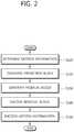
- FIG. 2is a flow chart illustrating a method of encoding video data in an inter prediction mode according to the present invention.
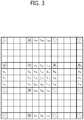
- FIG. 3is a conceptual diagram illustrating pixel positions indicated by a motion vector according to the present invention.
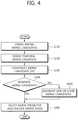
- FIG. 4is a flow chart illustrating a method of encoding motion information in a merge mode according to the present invention.
- FIG. 5is a conceptual diagram illustrating positions of spatial merge candidate blocks according to the present invention.
- FIG. 6is a conceptual diagram illustrating positions of spatial merge candidate blocks in an asymmetric partitioning mode according to the present invention.
- FIG. 7is another conceptual diagram illustrating positions of spatial merge candidate blocks in another asymmetric partitioning mode according to the present invention.
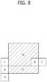
- FIG. 8is another conceptual diagram illustrating positions of spatial merge candidate blocks in another asymmetric partitioning mode according to the present invention.
- FIG. 9is another conceptual diagram illustrating positions of spatial merge candidate blocks in another asymmetric partitioning mode according to the present invention.
- FIG. 10is a conceptual diagram illustrating position of temporal merge candidate block according to the present invention.
- FIG. 11is a conceptual diagram illustrating a method of storing motion information according to the present invention.
- FIG. 12is a block diagram of an image decoding apparatus 200 according to the present invention.
- FIG. 13is a flow chart illustrating a method of decoding an image in inter prediction mode according to the present invention.
- FIG. 14is a flow chart illustrating a method of deriving motion information in merge mode.
- FIG. 15is a flow chart illustrating a procedure of generating a residual block in inter prediction mode according to the present invention.
- An image encoding apparatus and an image decoding apparatusmay be a user terminal such as a personal computer, a personal mobile terminal, a mobile multimedia player, a smartphone or a wireless communication terminal.
- the image encoding device and the image decoding devicemay be include a communication unit for communicating with various devices, a memory for storing various programs and data used to encode or decode images.
- FIG. 1is a block diagram of an image coding apparatus 100 according to the present invention.
- the image coding apparatus 100includes a picture division unit 110 , an intra prediction unit 120 , an inter prediction unit 130 , a transform unit 140 , a quantization unit 150 , a scanning unit 160 , an entropy coding unit 170 , an inverse quantization/transform unit 180 , a post-processing unit 190 and a picture storing unit 195 .
- An LCUincludes one or more coding units.
- the LCUhas a recursive quad tree structure to specify a division structure of the LCU. Parameters for specifying the maximum size and the minimum size of the coding unit are included in a sequence parameter set.
- the division structureis specified by one or more split coding unit flags (split_cu_flags).
- split_cu_flagsThe size of a coding unit is 2N ⁇ 2N. If the size of the LCU is 64 ⁇ 64 and the size of a smallest coding unit (SCU) is 8 ⁇ 8, the size of the coding unit may be 64 ⁇ 64, 32 ⁇ 32, 16 ⁇ 16 or 8 ⁇ 8.
- a coding unitincludes one or more transform units.
- the transform unithas a recursive quad tree structure to specify a division structure of the coding unit.
- the division structureis specified by one or more split transform unit flags (split_tu_flags). Parameters for specifying the maximum size and the minimum size of the luma transform unit are included in a sequence parameter set.
- the intra prediction unit 120determines an intra prediction mode of a current prediction unit and generates a prediction block using the intra prediction mode.
- the inter prediction unit 130determines motion information of a current prediction unit using one or more reference pictures stored in the picture storing unit 195 , and generates a prediction block of the prediction unit.
- the motion informationincludes one or more reference picture indexes and one or more motion vectors.
- the transform unit 140transforms a residual block to generate a transformed block.
- the residual blockhas the same size of the transform unit. If the prediction unit is larger than the transform unit, the residual signals between the current block and the prediction block are partitioned into multiple residual blocks.
- the quantization unit 150determines a quantization parameter for quantizing the transformed block.
- the quantization parameteris a quantization step size.
- the quantization parameteris determined per quantization unit.
- the size of the quantization unitmay vary and be one of allowable sizes of coding unit. If a size of the coding unit is equal to or larger than a minimum size of the quantization unit, the coding unit becomes the quantization unit.
- a plurality of coding unitsmay be included in a quantization unit of minimum size. The minimum size of the quantization unit is determined per picture and a parameter for specifying the minimum size of the quantization unit is included in a picture parameter set.
- the quantization parameter predictoris generated by using quantization parameters of neighboring coding units and a quantization parameter of previous coding unit as follows.
- a left quantization parameter, an above quantization parameter and a previous quantization parameterare sequentially retrieved in this order.
- An average of the first two available quantization parameters retrieved in that orderis set as the quantization parameter predictor when two or more quantization parameters are available, and when only one quantization parameter is available, the available quantization parameter is set as the quantization parameter predictor. That is, if the left and above quantization parameters are available, an average of the left and above quantization parameters is set as the quantization parameter predictor. If only one of the left and above quantization parameters is available, an average of the available quantization parameter and the previous quantization parameters is set as the quantization parameter predictor. If both of the left and above quantization parameters are unavailable, the previous quantization parameter is set as the quantization parameter predictor. The average is rounded off.
- the quantization unit 150quantizes the transformed block using a quantization matrix and the quantization parameter to generate a quantized block.
- the quantized blockis provided to the inverse quantization/transform unit 180 and the scanning unit 160 .
- the scanning unit 160determines applies a scan pattern to the quantized block.
- a diagonal scanis used as the scan pattern if CABAC is used for entropy coding.
- the quantized coefficients of the quantized blockare split into coefficient components.
- the coefficient componentsare significant flags, coefficient signs and coefficient levels.
- the diagonal scanis applied to each of the coefficient components.
- the significant coefficientindicates whether the corresponding quantized coefficient is zero or not.
- the coefficient signindicates a sign of non-zero quantized coefficient, and the coefficient level indicates an absolute value of non-zero quantized coefficient.
- the quantized blockis divided into multiple subsets and the diagonal scan is applied to each subset. Significant flags, coefficient signs and coefficients levels of each subset are scanned respectively according to the diagonal scan.
- the predetermined sizeis 4 ⁇ 4.
- the subsetis a 4 ⁇ 4 block containing 16 transform coefficients.
- the scan pattern for scanning the subsetsis the same as the scan pattern for scanning the coefficient components.
- the significant flags, the coefficient signs and the coefficients levels of each subsetare scanned in the reverse direction.
- the subsetsare also scanned in the reverse direction.
- a parameter indicating last non-zero coefficient positionis encoded and transmitted to a decoding side.
- the parameter indicating last non-zero coefficient positionspecifies a position of last non-zero quantized coefficient within the quantized block.
- a non-zero subset flagis defined for each subset other than the first subset and the last subset and is transmitted to the decoding side.
- the first subsetcovers a DC coefficient.
- the last subsetcovers the last non-zero coefficient.
- the non-zero subset flagindicates whether the subset contains non-zero coefficients or not.
- the entropy coding unit 170entropy-codes the scanned component by the scanning unit 160 , intra prediction information received from the intra prediction unit 120 , motion information received from the inter prediction unit 130 , and so on.
- the inverse quantization/transform unit 180inversely quantizes the quantized coefficients of the quantized block, and inversely transforms the inverse quantized block to generate residual signals.
- the post-processing unit 190performs a deblocking filtering process for removing blocking artifact generated in a reconstructed picture.
- the picture storing unit 195receives post-processed image from the post-processing unit 190 , and stores the image in picture units.
- a picturemay be a frame or a field.
- Motion information of a current blockis determined (S 110 ).
- the current blockis a prediction unit.
- a size of the current blockis determined by a size and a partitioning mode of the coding unit.
- the prediction blockis generated by copying a block of the reference picture specified by the motion vector. If the motion vector indicates a sub-pixel location, the prediction block is generated by interpolating the pixels of the reference picture.
- the motion vectoris given in quarter-pixel units.
- the pixels labeled with L 0 , R 0 , R 1 , L 1 , A 0 and B 0are integer position pixels of the reference picture and the pixels labeled with a L0 to r L0 at sub-pixel locations are fractional pixels to be interpolated using an interpolation filter which is selected based on the motion vector.
- the pixel labeled with e L0 , i L0 or p L0is generated by applying an interpolation filter to vertically nearest interpolated pixels each of which includes a character ‘a’ within its label. If a pixel to be interpolated is located at a sub-pixel location g L0 , k L0 or r L0 , the pixel labeled with g L0 , k L0 or r L0 is generated by applying an interpolation filter to vertically nearest interpolated pixels each of which includes a character ‘c’ within its label.
- the pixel labeled with f L0 , j L0 or q L0is generated by applying an interpolation filter to vertically neighboring interpolated pixels each of which includes a character ‘c’ within its label.
- the interpolation filteris determined based on the sub-pixel location of the pixel to be interpolated, or based on a prediction mode and a sub-pixel location of the pixel to be interpolated.
- the sub-pixel location Hindicates a half-pixel location in interpolation direction.
- the locations b L0 , h L0 , i L0 , j L0 , and k L0correspond to the sub-pixel location H.
- the sub-pixel locations FL and FRindicate a quarter-pixel location in interpolation direction.
- the locations a L0 , d L0 , e L0 , f L0 , and g L0correspond to the sub-pixel location FL
- the locations c L0 , n L0 , p L0 , q L0 , and r L0correspond to the sub-pixel location FR.
- 6-tap symmetry filtermay be used to interpolate pixels of half-pixel location H
- 5-tap asymmetry filtermay be used to interpolate pixels of quarter-pixel location FL or FR
- 8-tap symmetry filtermay be used for the half-pixel location H
- 8-tap asymmetry filtermay be used for the quarter-pixel location FL and FR.
- the filtermay be determined by only the sub-pixel location of the pixel to be interpolated.
- 8-tap symmetry filtermay be used to interpolate pixels of half-pixel locations and 7-tap asymmetry filter or 6-tap asymmetry filter may be used to interpolate pixels of quarter-pixel locations.
- same filter or another filter having smaller number of tapsmay be used to interpolate pixels of sub-pixel locations.
- the residual blockis encoded (S 140 ).
- the residual blockis encoded by the transform unit 140 , the quantization unit 150 , the scanning unit 160 and the entropy coding unit 170 of FIG. 1 .
- the motion informationis encoded (S 150 ).
- the motion informationmay be encoded predictively using spatial candidates and a temporal candidate of the current block.
- the motion informationis encoded in a skip mode, a merge mode or an AMVP mode.
- the prediction unithas the size of coding unit and the motion information is encoded using the same method as that of the merge mode.
- the motion information of the current prediction unitis equal to motion information of one candidate.
- the AMVP modethe motion vector of the motion information is predictively coded using one or more motion vector candidate.
- FIG. 4is a flow chart illustrating a method of encoding motion information in the merge mode according to the present invention.
- FIG. 5is a conceptual diagram illustrating positions of spatial merge candidate blocks according to the present invention.
- the merge candidate blockis a left block (block A), an above block (block B), an above-right block (block C), a left-below block (block D) or an above-left block (block E) of the current block.
- the blocksare prediction blocks.
- the above-left block (block E)is set as merge candidate block when one or more of the blocks A, B, C and D are unavailable.
- the motion information of an available merge candidate block Nis set as a spatial merge candidate N. N is A, B, C, D or E.
- the spatial merge candidatemay be set as unavailable according to the shape of the current block and the position of the current block. For example, if the coding unit is split into two prediction units (block P 0 and block P 1 ) using asymmetric partitioning, it is probable that the motion information of the block P 0 is not equal to the motion information of the block P 1 . Therefore, if the current block is the asymmetric block P 1 , the block P 0 is set as unavailable candidate block as shown in FIGS. 6 to 9 .
- a coding unitis partitioned into two asymmetric prediction blocks P 0 and P 1 and the partitioning mode is an nL ⁇ 2N mode.
- the size of the block P 0is hN ⁇ 2N and the size of the block P 1 is (2 ⁇ h)N ⁇ 2N.
- the value of his 1 ⁇ 2.
- the current blockis the block P 1 .
- the blocks A, B, C, D and Eare spatial merge candidate blocks.
- the block P 0is the spatial merge candidate block A.
- the spatial merge candidate Ais set as unavailable not to be listed on the merge candidate list. Also, the spatial merge candidate block B, C, D or E having the same motion information of the spatial merge candidate block A is set as unavailable.
- FIG. 7is another conceptual diagram illustrating positions of spatial merge candidate blocks in an asymmetric partitioning mode according to the present invention.
- a coding unitis partitioned into two asymmetric prediction blocks P 0 and P 1 and the partitioning mode is an nR ⁇ 2N mode.
- the size of the block P 0is (2 ⁇ h)N ⁇ 2N and the size of the block P 1 is hN ⁇ 2N.
- the value of his 1 ⁇ 2.
- the current blockis the block P 1 .
- the blocks A, B, C, D and Eare spatial merge candidate blocks.
- the block P 0is the spatial merge candidate block A.
- the spatial merge candidate Ais set as unavailable not to be listed on the merge candidate list. Also, the spatial merge candidate block B, C, D or E having the same motion information of the spatial merge candidate block A is set as unavailable.
- a coding unitis partitioned into two asymmetric prediction blocks P 0 and P 1 and the partitioning mode is a 2N ⁇ nU mode.
- the size of the block P 0is 2N ⁇ hN and the size of the block P 1 is 2N ⁇ (2 ⁇ h)N.
- the value of his 1 ⁇ 2.
- the current blockis the block P 1 .
- the blocks A, B, C, D and Eare spatial merge candidate blocks.
- the block P 0is the spatial merge candidate block B.
- a coding unitis partitioned into two asymmetric prediction blocks P 0 and P 1 and the partitioning mode is a 2N ⁇ nD mode.
- the size of the block P 0is 2N ⁇ (2 ⁇ h)N and the size of the block P 1 is 2N ⁇ hN.
- the value of his 1 ⁇ 2.
- the current blockis the block P 1 .
- the blocks A, B, C, D and Eare spatial merge candidate blocks.
- the block P 0is the spatial merge candidate block B.
- the spatial merge candidate Bis set as unavailable not to be listed on the merge candidate list. Also, the spatial merge candidate block C, D or E having the same motion information of the spatial merge candidate block B is set as unavailable.
- the spatial merge candidatemay also be set as unavailable based on merge area. If the current block and the spatial merge candidate block belong to same merge area, the spatial merge candidate block is set as unavailable.
- the merge areais a unit area in which motion estimation is performed and information specifying the merge area is included in a bit stream.
- a temporal merge candidateis derived (S 220 ).
- the temporal merge candidateincludes a reference picture index and a motion vector of the temporal merge candidate.
- the reference picture index of the temporal merge candidatemay be derived using one or more reference picture indexes of neighboring block. For example, one of the reference picture indexes of a left neighboring block, an above neighboring block and a corner neighboring block is set as the reference picture index of the temporal merge candidate.
- the corner neighboring blockis one of an above-right neighboring block, a left-below neighboring block and an above-left neighboring block.
- the reference picture index of the temporal merge candidatemay be set to zero to reduce the complexity.
- the motion vector of the temporal merge candidatemay be derived as follows.
- a temporal merge candidate pictureis determined.
- the temporal merge candidate pictureincludes a temporal merge candidate block.
- One temporal merge candidate pictureis used within a slice.
- a reference picture index of the temporal merge candidate picturemay be set to zero.
- the current sliceis a P slice
- one of the reference pictures of the reference picture list 0is set as the temporal merge candidate picture.
- the current sliceis a B slice
- one of the reference pictures of the reference picture lists 0 and 1is set as the temporal merge candidate picture.
- a list indicator specifying whether the temporal merge candidate picture belongs to the reference picture lists 0 or 1is included in a slice header if the current slice is a B slice.
- the reference picture index specifying the temporal merge candidate picturemay be included in the slice header.
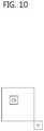
- FIG. 10is a conceptual diagram illustrating position of temporal merge candidate block according to the present invention.
- a first candidate blockmay be a right-below corner block (block H) of the block C.
- the block Chas same size and same location of the current block and is located within the temporal merge candidate picture.
- a second candidate blockis a block covering an upper-left pixel of the center of the block C.
- the temporal merge candidate blockmay be the first candidate block or the second candidate block. If the first candidate block is available, the first candidate block is set as the temporal merge candidate block. If the first candidate block is unavailable, the second candidate block is set as the temporal merge candidate block. If the second candidate block is unavailable, the temporal merge candidate block is set as unavailable.
- the temporal merge candidate blockis determined based on the position of the current block. For example, if the current block is adjacent to a lower LCU (that is, if the first candidate block belongs to a lower LCU), the first candidate block may be changed into a block within a current LCU or is set as unavailable.
- the first and second candidate blocksmay be changed into another block based on each position of the candidate block within a motion vector storing unit.
- the motion vector storing unitis a basic unit storing motion information of reference pictures.
- FIG. 11is a conceptual diagram illustrating a method of storing motion information according to the present invention.
- the motion storing unitmay be a 16 ⁇ 16 block.
- the motion vector storing unitmay be divided into sixteen 4 ⁇ 4 bocks. If the motion vector storing unit is a 16 ⁇ 16 block, the motion information is stored per the motion vector storing unit. If the motion vector storing unit includes multiple prediction units of reference picture, motion information of a predetermined prediction unit of the multiple prediction units is stored in memory to reduce amount of motion information to be stored in memory.
- the predetermined prediction unitmay be a block covering one of the sixteen 4 ⁇ 4 blocks.
- the predetermined prediction unitmay be a block covering a block C 3 , a block BR. Or the predetermined prediction unit may be a block covering a block UL.
- the candidate blockif the candidate block does not include the predetermined block, the candidate block is changed into a block including the predetermined block.
- the motion vector of the temporal merge candidate blockis set as the motion vector of the temporal merge candidate.
- a merge candidate listis constructed (S 230 ).
- the available spatial candidates and the available temporal candidateare listed in a predetermined order.
- the spatial merge candidatesare listed up to four in the order of A, B, C, D and E.
- the temporal merge candidatemay be listed between B and C or after the spatial candidates.
- merge candidate listIf the number of merge candidates listed in the merge candidate list is smaller than a predetermined number of the merge candidates, one or more merge candidates are generated (S 250 ). The generated merge candidate is listed after the last available merge candidate.
- a merge predictoris selected among the merge candidates of the merge list, a merge index specifying the merge predictor is encoded (S 260 ).
- FIG. 12is a block diagram of an image decoding apparatus 200 according to the present invention.
- the entropy decoding unit 210extracts the intra prediction information, the inter prediction information and the quantized coefficient components from a received bit stream using a context-adaptive binary arithmetic decoding method.
- the inverse scanning unit 220applies an inverse scan pattern to the quantized coefficient components to generate quantized block.
- the inverse scan patternis a diagonal scan.
- the quantized coefficient componentsinclude the significant flags, the coefficient signs and the coefficients levels.
- the significant flags, the coefficient signs and the coefficients levelsare inversely scanned in the unit of subset using the diagonal scan to generate subsets, and the subsets are inversely scanned using the diagonal scan to generate the quantized block.
- the predetermined sizeis equal to the size of the subset.
- the subsetis a 4 ⁇ 4 block including 16 transform coefficients.
- the significant flags, the coefficient signs and the coefficient levelsare inversely scanned in the reverse direction.
- the subsetsare also inversely scanned in the reverse direction.
- a parameter indicating last non-zero coefficient position and the non-zero subset flagsare extracted from the bit stream.
- the number of encoded subsetsis determined based on the parameter indicating last non-zero coefficient position.
- the non-zero subset flagis used to determine whether the corresponding subset has at least one non-zero coefficient. If the non-zero subset flag is equal to 1, the subset is generated using the diagonal scan. The first subset and the last subset are generated using the inverse scan pattern.
- the inverse quantization unit 230receives the differential quantization parameter from the entropy decoding unit 210 and generates the quantization parameter predictor to generate the quantization parameter of the coding unit.
- the operation of generating the quantization parameter predictoris the same as the operation of the quantization unit 150 of FIG. 1 .
- the quantization parameter of the current coding unitis generated by adding the differential quantization parameter and the quantization parameter predictor. If the differential quantization parameter for the current coding unit is not transmitted from an encoding side, the differential quantization parameter is set to zero.
- the inverse transform unit 240inversely transforms the inverse-quantized block to generate a residual block.
- An inverse transform matrixis adaptively determined according to the prediction mode and the size of the transform unit.
- the inverse transform matrixis a DCT-based integer transform matrix or a DST-based integer transform matrix. In inter prediction, the DCT-based integer transforms are used.
- the intra prediction unit 250derives an intra prediction mode of a current prediction unit using the received intra prediction information, and generates a prediction block according to the derived intra prediction mode.
- the inter prediction unit 260derives the motion information of the current prediction unit using the received inter prediction information, and generates a prediction block using the motion information.
- the post-processing unit 270operates the same as the post-processing unit 180 of FIG. 1 .
- the picture storing unit 280receives post-processed image from the post-processing unit 270 , and stores the image in picture units.
- a picturemay be a frame or a field.
- the adder 290adds the restored residual block and a prediction block to generate a reconstructed block.
- FIG. 13is a flow chart illustrating a method of decoding an image in inter prediction mode according to the present invention.
- Motion information of a current blockis derived (S 310 ).
- the current blockis a prediction unit.
- a size of the current blockis determined by the size of the coding unit and the partitioning mode.
- the motion informationvaries according to a prediction type. If the prediction type is a uni-directional prediction, the motion information includes a reference index specifying a picture of a reference list 0, and a motion vector. If the prediction type is a bi-directional prediction, the motion information includes a reference index specifying a picture of a reference list 0, a reference index specifying a picture of a reference list 1, and a list 0 motion vector and a list 1 motion vector.
- the motion informationis adaptively decoded according the coding mode of the motion information.
- the coding mode of the motion informationis determined by a skip flag and a merge flag. If the skip flag is equal to 1, the merge flag does not exist and the coding mode is a skip mode. If the skip flag is equal to 0 and the merge flag is equal to 1, the coding mode is a merge mode. If the skip flag and the merge flag are equal to 0, the coding mode is an AMVP mode.
- a prediction block of the current blockis generated using the motion information (S 320 ).
- the prediction blockis generated by copying a block of the reference picture specified by the motion vector. If the motion vector indicates a sub-pixel location, the prediction block is generated by interpolating the pixels of the reference picture.
- the motion vectoris given in quarter-pixel units.
- the pixels labeled with L 0 , R 0 , R 1 , L 1 , A 0 and B 0are integer position pixels of the reference picture and the pixels labeled with a L0 to r L0 at sub-pixel locations are fractional pixels to be interpolated using an interpolation filter which is selected based on the motion vector.
- the pixel labeled with e L0 , i L0 or p L0is generated by applying an interpolation filter to vertically nearest interpolated pixels each of which includes a character ‘a’ within its label. If a pixel to be interpolated is located at a sub-pixel location g L0 , k L0 or r L0 , the pixel labeled with g L0 , k L0 or r L0 is generated by applying an interpolation filter to vertically nearest interpolated pixels each of which includes a character ‘c’ within its label.
- the pixel labeled with f L0 , j L0 or q L0is generated by applying an interpolation filter to vertically neighboring interpolated pixels each of which includes a character ‘c’ within its label.
- the interpolation filteris determined based on the sub-pixel location of the pixel to be interpolated, or based on a prediction mode and a sub-pixel location of the pixel to be interpolated.
- 6-tap symmetry filtermay be used to interpolate pixels of half-pixel location H
- 5-tap asymmetry filtermay be used to interpolate pixels of quarter-pixel location FL or FR
- 8-tap symmetry filtermay be used for the half-pixel location H
- 8-tap asymmetry filtermay be used for the quarter-pixel location FL and FR.
- the filtermay be determined by only the sub-pixel location of the pixel to be interpolated.
- 8-tap symmetry filtermay be used to interpolate pixels of half-pixel locations and 7-tap asymmetry filter or 6-tap may be used to interpolate pixels of quarter-pixel locations.
- same filter or another filter having smaller number of tapsmay be used to interpolate pixels of sub-pixel locations.
- a residual blockis generated (S 330 ).
- the residual blockis generated by the entropy decoding unit 210 , the inverse scanning unit 220 , the inverse quantization unit 230 and the inverse transform unit 240 of FIG. 12 .
- a reconstructed blockis generated using the prediction block and the residual block (S 340 ).
- the prediction blockhas the same size of the prediction unit, and the residual block has the same size of the transform unit. Therefore, the residual signals and the prediction signals of same size are added to generate reconstructed signals.
- FIG. 14is a flow chart illustrating a method of deriving motion information in merge mode.
- Spatial merge candidatesare derived (S 420 ).
- the available spatial merge candidatesare the same as describe in S 210 of FIG. 4 .
- a temporal merge candidateis derived (S 430 ).
- the temporal merge candidateincludes a reference picture index and a motion vector of the temporal merge candidate.
- the reference index and the motion vector of the temporal merge candidateare the same as described in S 220 of FIG. 4 .
- a merge candidate listis constructed (S 440 ).
- the merge listis the same as described in S 230 of FIG. 4 .
- merge candidate listIf the number of merge candidates listed in the merge candidate list is smaller than a predetermined number of the merge candidates, one or more merge candidates are generated (S 460 ).
- the generated merge candidateis listed after the last available merge candidate.
- the merge candidateis generated as the same method described in S 250 of FIG. 4 .
- the merge candidate specified by the merge indexis set as the motion information of the current block (S 470 ).
- FIG. 15is a flow chart illustrating a procedure of generating a residual block in inter prediction mode according to the present invention.
- Quantized coefficient componentsare generated by the entropy decoding unit (S 510 ).
- a quantized blockis generated by inversely scanning the quantized coefficient components according to the diagonal scan (S 520 ).
- the quantized coefficient componentsinclude the significant flags, the coefficient signs and the coefficients levels.
- the significant flags, the coefficient signs and the coefficients levelsare inversely scanned in the unit of subset using the diagonal scan to generate subsets, and the subsets are inversely scanned using the diagonal scan to generate the quantized block.
- the predetermined sizeis equal to the size of the subset.
- the subsetis a 4 ⁇ 4 block including 16 transform coefficients.
- the significant flags, the coefficient signs and the coefficient levelsare inversely scanned in the reverse direction.
- the subsetsare also inversely scanned in the reverse direction.
- the parameter indicating last non-zero coefficient position and the non-zero subset flagsare extracted from the bit stream.
- the number of encoded subsetsis determined based on the parameter indicating last non-zero coefficient position.
- the non-zero subset flagsare used to determine whether the subset has at least one non-zero coefficient. If the non-zero subset flag is equal to 1, the subset is generated using the diagonal scan. The first subset and the last subset are generated using the inverse scan pattern.
- the quantized blockis inversely quantized using an inverse quantization matrix and a quantization parameter (S 530 ).
- a minimum size of quantization unitis determined.
- a parameter cu_qp_delta_enabled_info specifying the minimum sizeis extracted from a bit stream, and the minimum size of the quantization unit is determined by the following equation.
- Log 2(MinQUSize)Log 2(MaxCUSize) ⁇ cu_qp_delta_enabled_info
- the MinQUSizeindicates the minimum size of the quantization unit
- the MaxCUSizeindicates the size of LCU.
- the parameter cu_qp_delta_enabled_infois extracted from a picture parameter set.
- a differential quantization parameter of the current coding unitis derived.
- the differential quantization parameteris included per quantization unit. Therefore, if the size of the current coding unit is equal to or larger than the minimum size of the quantization unit, the differential quantization parameter for the current coding unit is restored. If the differential quantization parameter does not exist, the differential quantization parameter is set to zero. If multiple coding units belong to a quantization unit, the first coding unit containing at least one non-zero coefficient in the decoding order contains the differential quantization unit.
- a coded differential quantization parameteris arithmetically decoded to generate bin string indicating the absolute value of the differential quantization parameter and a bin indicating the sign of the differential quantization parameter.
- the bin stringmay be a truncated unary code. If the absolute value of the differential quantization parameter is zero, the bin indicating the sign does not exist.
- the differential quantization parameteris derived using the bin string indicating the absolute value and the bin indicating the sign.
- a quantization parameter predictor of the current coding unitis derived.
- the quantization parameter predictoris generated by using quantization parameters of neighboring coding units and quantization parameter of previous coding unit as follows.
- a left quantization parameter, an above quantization parameter and a previous quantization parameterare sequentially retrieved in this order.
- An average of the first two available quantization parameters retrieved in that orderis set as the quantization parameter predictor when two or more quantization parameters are available, and when only one quantization parameter is available, the available quantization parameter is set as the quantization parameter predictor. That is, if the left and above quantization parameter are available, the average of the left and above quantization parameter is set as the quantization parameter predictor. If only one of the left and above quantization parameter is available, the average of the available quantization parameter and the previous quantization parameter is set as the quantization parameter predictor. If both of the left and above quantization parameter are unavailable, the previous quantization parameter is set as the quantization parameter predictor.
- the quantization parameter predictor for the first coding unit in decoding orderis derived and used for the other coding units.
- the quantization parameter of the current coding unitis generated using the differential quantization parameter and the quantization parameter predictor.
Landscapes
- Engineering & Computer Science (AREA)
- Multimedia (AREA)
- Signal Processing (AREA)
- Computing Systems (AREA)
- Theoretical Computer Science (AREA)
- Physics & Mathematics (AREA)
- Discrete Mathematics (AREA)
- General Physics & Mathematics (AREA)
- Compression Or Coding Systems Of Tv Signals (AREA)
Abstract
Description
| TABLE 1 | ||||
| Prediction | Sub-Pixel | |||
| mode | Location | Filter coefficient | ||
| Uni-directional | H | {2, −8, 36, 36, −8, 2} | ||
| prediction | FL | {−3, 51, 20, −7, 2} | ||
| FR | {2, −7, 20, 51, −3} | |||
| Bi-directional | H | {−1, 4, −11, 40, 40, −11, 4, −1} | ||
| prediction | FL | {−1, 4, −10, 57, 19, −7, 3, −1} | ||
| FR | {−1, 3, −7, 19, 57, −10, 4, −1} | |||
Log 2(MinQUSize)=Log 2(MaxCUSize)−cu_qp_delta_enabled_info
Claims (9)
Priority Applications (1)
| Application Number | Priority Date | Filing Date | Title |
|---|---|---|---|
| US16/242,546US10873757B2 (en) | 2011-11-07 | 2019-01-08 | Method of encoding video data |
Applications Claiming Priority (8)
| Application Number | Priority Date | Filing Date | Title |
|---|---|---|---|
| KR1020110115348AKR20130050149A (en) | 2011-11-07 | 2011-11-07 | Method for generating prediction block in inter prediction mode |
| KR10-2011-0115348 | 2011-11-07 | ||
| PCT/CN2012/084018WO2013067903A1 (en) | 2011-11-07 | 2012-11-02 | Method of decoding video data |
| US201414349979A | 2014-04-04 | 2014-04-04 | |
| US14/618,833US9351012B2 (en) | 2011-11-07 | 2015-02-10 | Method of decoding video data |
| US14/692,680US9648343B2 (en) | 2011-11-07 | 2015-04-21 | Method of decoding video data |
| US15/481,954US10212449B2 (en) | 2011-11-07 | 2017-04-07 | Method of encoding video data |
| US16/242,546US10873757B2 (en) | 2011-11-07 | 2019-01-08 | Method of encoding video data |
Related Parent Applications (1)
| Application Number | Title | Priority Date | Filing Date |
|---|---|---|---|
| US15/481,954ContinuationUS10212449B2 (en) | 2011-11-07 | 2017-04-07 | Method of encoding video data |
Publications (2)
| Publication Number | Publication Date |
|---|---|
| US20190141349A1 US20190141349A1 (en) | 2019-05-09 |
| US10873757B2true US10873757B2 (en) | 2020-12-22 |
Family
ID=48288520
Family Applications (8)
| Application Number | Title | Priority Date | Filing Date |
|---|---|---|---|
| US14/349,979ActiveUS8982957B2 (en) | 2011-11-07 | 2012-11-02 | Method of decoding video data |
| US14/618,833ActiveUS9351012B2 (en) | 2011-11-07 | 2015-02-10 | Method of decoding video data |
| US14/692,680Expired - Fee RelatedUS9648343B2 (en) | 2011-11-07 | 2015-04-21 | Method of decoding video data |
| US14/692,679ActiveUS9615106B2 (en) | 2011-11-07 | 2015-04-21 | Method of decoding video data |
| US14/692,690ActiveUS9641860B2 (en) | 2011-11-07 | 2015-04-21 | Method of decoding video data |
| US14/692,691ActiveUS9635384B2 (en) | 2011-11-07 | 2015-04-21 | Method of decoding video data |
| US15/481,954ActiveUS10212449B2 (en) | 2011-11-07 | 2017-04-07 | Method of encoding video data |
| US16/242,546ActiveUS10873757B2 (en) | 2011-11-07 | 2019-01-08 | Method of encoding video data |
Family Applications Before (7)
| Application Number | Title | Priority Date | Filing Date |
|---|---|---|---|
| US14/349,979ActiveUS8982957B2 (en) | 2011-11-07 | 2012-11-02 | Method of decoding video data |
| US14/618,833ActiveUS9351012B2 (en) | 2011-11-07 | 2015-02-10 | Method of decoding video data |
| US14/692,680Expired - Fee RelatedUS9648343B2 (en) | 2011-11-07 | 2015-04-21 | Method of decoding video data |
| US14/692,679ActiveUS9615106B2 (en) | 2011-11-07 | 2015-04-21 | Method of decoding video data |
| US14/692,690ActiveUS9641860B2 (en) | 2011-11-07 | 2015-04-21 | Method of decoding video data |
| US14/692,691ActiveUS9635384B2 (en) | 2011-11-07 | 2015-04-21 | Method of decoding video data |
| US15/481,954ActiveUS10212449B2 (en) | 2011-11-07 | 2017-04-07 | Method of encoding video data |
Country Status (15)
| Country | Link |
|---|---|
| US (8) | US8982957B2 (en) |
| EP (5) | EP2752007A4 (en) |
| JP (6) | JP5827412B2 (en) |
| KR (4) | KR20130050149A (en) |
| CN (7) | CN104869400B (en) |
| AU (5) | AU2012334553B2 (en) |
| BR (5) | BR112014007593B1 (en) |
| CA (5) | CA2849029C (en) |
| IL (5) | IL231707A (en) |
| MX (5) | MX356738B (en) |
| MY (3) | MY201790A (en) |
| PH (7) | PH12014500962A1 (en) |
| RU (5) | RU2621967C1 (en) |
| SG (5) | SG11201400667QA (en) |
| WO (1) | WO2013067903A1 (en) |
Families Citing this family (36)
| Publication number | Priority date | Publication date | Assignee | Title |
|---|---|---|---|---|
| KR20120068743A (en)* | 2010-12-17 | 2012-06-27 | 한국전자통신연구원 | Method for inter prediction and apparatus thereof |
| MX336301B (en)* | 2011-06-28 | 2016-01-14 | Samsung Electronics Co Ltd | Method for image interpolation using asymmetric interpolation filter and apparatus therefor. |
| KR20130050149A (en)* | 2011-11-07 | 2013-05-15 | 오수미 | Method for generating prediction block in inter prediction mode |
| JP5900308B2 (en)* | 2011-12-16 | 2016-04-06 | 株式会社Jvcケンウッド | Moving picture coding apparatus, moving picture coding method, and moving picture coding program |
| FR3032583B1 (en)* | 2015-02-06 | 2018-03-02 | Orange | METHOD OF ENCODING DIGITAL IMAGE, DECODING METHOD, DEVICES, AND COMPUTER PROGRAMS |
| RU2684193C1 (en)* | 2015-05-21 | 2019-04-04 | Хуавэй Текнолоджиз Ко., Лтд. | Device and method for motion compensation in video content |
| JP6464272B2 (en)* | 2015-08-20 | 2019-02-06 | 日本放送協会 | Image encoding apparatus, image decoding apparatus, and programs thereof |
| EP3383040A4 (en)* | 2016-01-11 | 2018-10-17 | Samsung Electronics Co., Ltd. | Image encoding method and apparatus, and image decoding method and apparatus |
| WO2017176092A1 (en)* | 2016-04-08 | 2017-10-12 | 한국전자통신연구원 | Method and device for inducing motion prediction information |
| US10602176B2 (en) | 2016-04-15 | 2020-03-24 | Google Llc | Coding interpolation filter type |
| WO2018008906A1 (en) | 2016-07-05 | 2018-01-11 | 주식회사 케이티 | Method and apparatus for processing video signal |
| US10721489B2 (en)* | 2016-09-06 | 2020-07-21 | Qualcomm Incorporated | Geometry-based priority for the construction of candidate lists |
| US10341659B2 (en)* | 2016-10-05 | 2019-07-02 | Qualcomm Incorporated | Systems and methods of switching interpolation filters |
| US10785477B2 (en) | 2016-10-06 | 2020-09-22 | Lg Electronics Inc. | Method for processing video on basis of inter prediction mode and apparatus therefor |
| US10623746B2 (en)* | 2017-12-07 | 2020-04-14 | Tencent America LLC | Method and apparatus for video coding |
| US11647179B2 (en)* | 2018-06-25 | 2023-05-09 | B1 Institute Of Image Technology, Inc. | Method and apparatus for encoding/decoding images |
| CN110662065A (en)* | 2018-06-29 | 2020-01-07 | 财团法人工业技术研究院 | Image data decoding method and decoder, image data encoding method and encoder |
| CN112565785B (en) | 2018-12-28 | 2022-04-26 | 杭州海康威视数字技术股份有限公司 | Coding and decoding method and equipment thereof |
| US11503283B2 (en) | 2018-12-28 | 2022-11-15 | Jvckenwood Corporation | Dynamic image decoding device, dynamic image decoding method, dynamic image decoding program, dynamic image encoding device, dynamic image encoding method, and dynamic image encoding program |
| KR102790776B1 (en) | 2019-03-12 | 2025-04-02 | 엘지전자 주식회사 | Video encoding/decoding method, device and method for transmitting bitstream |
| CN114208194A (en)* | 2019-03-28 | 2022-03-18 | 交互数字Vc控股法国公司 | Inter prediction parameter derivation for video encoding and decoding |
| MX2021011619A (en)* | 2019-04-01 | 2021-10-13 | Beijing Bytedance Network Tech Co Ltd | Using interpolation filters for history based motion vector prediction. |
| KR102635319B1 (en) | 2019-08-20 | 2024-02-07 | 베이징 바이트댄스 네트워크 테크놀로지 컴퍼니, 리미티드 | Selective use of alternative interpolation filters in video processing |
| JP2021048532A (en) | 2019-09-19 | 2021-03-25 | キヤノン株式会社 | Image coding device, image decoding device and their control methods and programs |
| JP7267885B2 (en)* | 2019-09-20 | 2023-05-02 | Kddi株式会社 | Image decoding device, image decoding method and program |
| JP2021052241A (en)* | 2019-09-20 | 2021-04-01 | Kddi株式会社 | Image decoding device, image decoding method, and program |
| PT3932064T (en) | 2019-09-23 | 2023-06-05 | Huawei Tech Co Ltd | An encoder, a decoder and corresponding methods of complexity reduction on intra prediction for the planar mode |
| CN113840148A (en)* | 2020-06-24 | 2021-12-24 | Oppo广东移动通信有限公司 | Inter-frame prediction method, encoder, decoder, and computer storage medium |
| CN114071157A (en)* | 2020-07-29 | 2022-02-18 | Oppo广东移动通信有限公司 | Inter-frame prediction method, encoder, decoder, and computer storage medium |
| WO2023028964A1 (en) | 2021-09-02 | 2023-03-09 | Nvidia Corporation | Parallel processing of video frames during video encoding |
| WO2023028965A1 (en)* | 2021-09-02 | 2023-03-09 | Nvidia Corporation | Hardware codec accelerators for high-performance video encoding |
| CN116097649A (en) | 2021-09-06 | 2023-05-09 | 辉达公司 | Parallel encoding of video frames without filtering dependencies |
| CN117255205A (en)* | 2022-06-16 | 2023-12-19 | 北京三星通信技术研究有限公司 | Video encoding and decoding method and corresponding equipment |
| EP4541025A1 (en) | 2022-06-16 | 2025-04-23 | Samsung Electronics Co., Ltd. | Video encoding/decoding method, and corresponding devices |
| US12238335B2 (en) | 2023-04-18 | 2025-02-25 | Nvidia Corporation | Efficient sub-pixel motion vector search for high-performance video encoding |
| US12316863B2 (en) | 2023-04-18 | 2025-05-27 | Nvidia Corporation | Chroma-from-luma mode selection for high-performance video encoding |
Citations (56)
| Publication number | Priority date | Publication date | Assignee | Title |
|---|---|---|---|---|
| US5339108A (en) | 1992-04-09 | 1994-08-16 | Ampex Corporation | Ordering and formatting coded image data and reconstructing partial images from the data |
| US5867602A (en) | 1994-09-21 | 1999-02-02 | Ricoh Corporation | Reversible wavelet transform and embedded codestream manipulation |
| US5881176A (en) | 1994-09-21 | 1999-03-09 | Ricoh Corporation | Compression and decompression with wavelet style and binary style including quantization by device-dependent parser |
| US5982935A (en) | 1997-04-11 | 1999-11-09 | National Semiconductor Corporation | Method and apparatus for computing MPEG video reconstructed DCT coefficients |
| US20020090207A1 (en) | 1994-09-26 | 2002-07-11 | Mitsubishi Denki Kabushiki Kaisha | Digital video signal record and playback device and method for selectively reproducing desired video information from an optical disk |
| US20030026335A1 (en) | 2001-06-29 | 2003-02-06 | Kadayam Thyagarajan | DCT compression using golomb-rice coding |
| US20030048208A1 (en)* | 2001-03-23 | 2003-03-13 | Marta Karczewicz | Variable length coding |
| US20040008784A1 (en) | 2002-06-17 | 2004-01-15 | Yoshihiro Kikuchi | Video encoding/decoding method and apparatus |
| US20050207495A1 (en) | 2004-03-10 | 2005-09-22 | Jayaram Ramasastry | Methods and apparatuses for compressing digital image data with motion prediction |
| US20060133481A1 (en) | 2004-12-22 | 2006-06-22 | Kabushiki Kaisha Toshiba | Image coding control method and device |
| US20060294171A1 (en) | 2005-06-24 | 2006-12-28 | Frank Bossen | Method and apparatus for video encoding and decoding using adaptive interpolation |
| US20070081587A1 (en) | 2005-09-27 | 2007-04-12 | Raveendran Vijayalakshmi R | Content driven transcoder that orchestrates multimedia transcoding using content information |
| US20070121731A1 (en) | 2005-11-30 | 2007-05-31 | Akiyuki Tanizawa | Image encoding/image decoding method and image encoding/image decoding apparatus |
| US20070189626A1 (en) | 2006-02-13 | 2007-08-16 | Akiyuki Tanizawa | Video encoding/decoding method and apparatus |
| US20070217507A1 (en) | 2006-03-15 | 2007-09-20 | Fujitsu Limited | Video coding apparatus |
| US20070274385A1 (en) | 2006-05-26 | 2007-11-29 | Zhongli He | Method of increasing coding efficiency and reducing power consumption by on-line scene change detection while encoding inter-frame |
| US7305034B2 (en) | 2002-04-10 | 2007-12-04 | Microsoft Corporation | Rounding control for multi-stage interpolation |
| US20080063068A1 (en) | 2002-07-15 | 2008-03-13 | Shunichi Sekiguchi | Image coding apparatus, image coding method, image decoding apparatus, image decoding method and communication apparatus |
| US20080170611A1 (en)* | 2007-01-17 | 2008-07-17 | Srikrishna Ramaswamy | Configurable functional multi-processing architecture for video processing |
| US20090067503A1 (en) | 2006-01-07 | 2009-03-12 | Electronics And Telecommunications Research Institute | Method and apparatus for video data encoding and decoding |
| US20090080521A1 (en) | 2004-01-30 | 2009-03-26 | Fraunhofer-Gesellschaft Zur Foerderung Der Angewandten Forschung E.V. | Video frame encoding and decoding |
| US20090116555A1 (en) | 2007-11-05 | 2009-05-07 | Canon Kabushiki Kaisha | Image encoding apparatus, method of controlling the same, and computer program |
| US20090141804A1 (en) | 2007-12-04 | 2009-06-04 | Zhao Xu Gang Wilf | Neighbor management for use in entropy encoding and methods for use therewith |
| US20090213930A1 (en) | 2008-02-22 | 2009-08-27 | Qualcomm Incorporated | Fast macroblock delta qp decision |
| US20090220005A1 (en) | 2008-03-03 | 2009-09-03 | Samsung Electronics Co., Ltd. | Method and apparatus for encoding and decoding image by using multiple reference-based motion prediction |
| US7620109B2 (en) | 2002-04-10 | 2009-11-17 | Microsoft Corporation | Sub-pixel interpolation in motion estimation and compensation |
| US20100086028A1 (en) | 2007-04-16 | 2010-04-08 | Kabushiki Kaisha Toshiba | Video encoding and decoding method and apparatus |
| US20100135389A1 (en) | 2007-06-26 | 2010-06-03 | Akiyuki Tanizawa | Method and apparatus for image encoding and image decoding |
| US20100150241A1 (en)* | 2006-04-03 | 2010-06-17 | Michael Erling Nilsson | Video coding |
| US20100262712A1 (en) | 2009-04-13 | 2010-10-14 | Samsung Electronics Co., Ltd. | Channel adaptive video transmission method, apparatus using the same, and system providing the same |
| US20120075436A1 (en)* | 2010-09-24 | 2012-03-29 | Qualcomm Incorporated | Coding stereo video data |
| US20120082215A1 (en) | 2010-09-30 | 2012-04-05 | Vivienne Sze | Simplified Binary Arithmetic Coding Engine |
| US20120082219A1 (en) | 2010-10-05 | 2012-04-05 | Microsoft Corporation | Content adaptive deblocking during video encoding and decoding |
| US20120140822A1 (en) | 2010-12-03 | 2012-06-07 | Qualcomm Incorporated | Video coding using function-based scan order for transform coefficients |
| US20120170650A1 (en) | 2011-01-05 | 2012-07-05 | Qualcomm Incorporated | Low complexity interpolation filtering with adaptive tap size |
| US20120195378A1 (en) | 2011-01-28 | 2012-08-02 | Qualcomm Incorporated | Pixel level adaptive intra-smoothing |
| US20120219064A1 (en) | 2011-02-24 | 2012-08-30 | Qualcomm Incorporated | Hierarchy of motion prediction video blocks |
| US8275036B2 (en) | 2001-11-30 | 2012-09-25 | Ntt Docomo, Inc. | Moving picture encoding device, moving picture decoding device, moving picture encoding method, moving picture decoding method, program, and computer readable recording medium storing program |
| US20120314027A1 (en) | 2004-12-17 | 2012-12-13 | Dong Tian | Method and System for Processing Multiview Videos for View Synthesis Using Motion Vector Predictor List |
| US20120328028A1 (en) | 2011-06-22 | 2012-12-27 | Texas Instruments Incorporated | Systems and methods for reducing blocking artifacts |
| US20130033612A1 (en) | 2011-08-01 | 2013-02-07 | Microsoft Corporation | Reduced latency video stabilization |
| US20130051475A1 (en)* | 2011-07-19 | 2013-02-28 | Qualcomm Incorporated | Coefficient scanning in video coding |
| US20130083844A1 (en)* | 2011-09-30 | 2013-04-04 | In Suk Chong | Coefficient coding for sample adaptive offset and adaptive loop filter |
| US20130083853A1 (en) | 2011-10-04 | 2013-04-04 | Qualcomm Incorporated | Motion vector predictor candidate clipping removal for video coding |
| US20130089145A1 (en)* | 2011-10-11 | 2013-04-11 | Qualcomm Incorporated | Most probable transform for intra prediction coding |
| US20130094952A1 (en) | 2011-10-18 | 2013-04-18 | General Electric Company | Transition nozzle |
| US20130094569A1 (en)* | 2011-10-13 | 2013-04-18 | Qualcomm Incorporated | Sample adaptive offset merged with adaptive loop filter in video coding |
| US20130101033A1 (en) | 2011-10-14 | 2013-04-25 | Qualcomm Incorporated | Coding non-symmetric distributions of data |
| US8498338B1 (en) | 2005-12-14 | 2013-07-30 | Ambarella, Inc. | Mode decision using approximate ½ pel interpolation |
| US20130301704A1 (en) | 2001-12-17 | 2013-11-14 | Microsoft Corporation | Video coding / decoding with re-oriented transforms and sub-block transform sizes |
| US20130322545A1 (en) | 2011-03-11 | 2013-12-05 | Sony Corporation | Image processing device and method |
| US20130329782A1 (en) | 2012-06-08 | 2013-12-12 | Qualcomm Incorporated | Adaptive upsampling filters |
| US20140161175A1 (en)* | 2012-12-07 | 2014-06-12 | Qualcomm Incorporated | Advanced residual prediction in scalable and multi-view video coding |
| US20140219339A1 (en) | 2011-10-24 | 2014-08-07 | Intercode Pte. Ltd. | Imaging decoding apparatus |
| US20140269926A1 (en) | 2011-11-07 | 2014-09-18 | Infobridge Pte. Ltd | Method of decoding video data |
| US20160191946A1 (en) | 2014-12-31 | 2016-06-30 | Microsoft Technology Licensing, Llc | Computationally efficient motion estimation |
Family Cites Families (54)
| Publication number | Priority date | Publication date | Assignee | Title |
|---|---|---|---|---|
| DE3853554T2 (en)* | 1987-06-09 | 1995-08-24 | Sony Corp | Motion vector estimation in television pictures. |
| US6208692B1 (en)* | 1997-12-31 | 2001-03-27 | Sarnoff Corporation | Apparatus and method for performing scalable hierarchical motion estimation |
| US6639942B1 (en)* | 1999-10-21 | 2003-10-28 | Toshiba America Electronic Components, Inc. | Method and apparatus for estimating and controlling the number of bits |
| US7663695B2 (en)* | 2000-05-05 | 2010-02-16 | Stmicroelectronics S.R.L. | Method and system for de-interlacing digital images, and computer program product therefor |
| AU2003285850A1 (en)* | 2002-04-23 | 2004-04-30 | Nokia Corporation | Method and device for indicating quantizer parameters in a video coding system |
| US7227901B2 (en)* | 2002-11-21 | 2007-06-05 | Ub Video Inc. | Low-complexity deblocking filter |
| US7609763B2 (en)* | 2003-07-18 | 2009-10-27 | Microsoft Corporation | Advanced bi-directional predictive coding of video frames |
| US7724827B2 (en)* | 2003-09-07 | 2010-05-25 | Microsoft Corporation | Multi-layer run level encoding and decoding |
| NO319629B1 (en)* | 2003-11-28 | 2005-09-05 | Tandberg Telecom As | Procedure for correcting interpolated pixel values |
| US7894530B2 (en)* | 2004-05-07 | 2011-02-22 | Broadcom Corporation | Method and system for dynamic selection of transform size in a video decoder based on signal content |
| US7583844B2 (en)* | 2005-03-11 | 2009-09-01 | Nokia Corporation | Method, device, and system for processing of still images in the compressed domain |
| CN101278563A (en)* | 2005-08-15 | 2008-10-01 | 诺基亚公司 | Method and apparatus for sub-pixel interpolation for update operations in video coding |
| US20080137732A1 (en)* | 2005-09-20 | 2008-06-12 | Mitsubishi Electric Corporation | Image encoding method and image decoding method, image encoder and image decoder, and image encoded bit stream and recording medium |
| US20070274396A1 (en)* | 2006-05-26 | 2007-11-29 | Ximin Zhang | Complexity adaptive skip mode estimation for video encoding |
| WO2007139266A1 (en)* | 2006-06-01 | 2007-12-06 | Electronics And Telecommunications Research Institute | Method and apparatus for video coding on pixel-wise prediction |
| US8422555B2 (en)* | 2006-07-11 | 2013-04-16 | Nokia Corporation | Scalable video coding |
| EP2047687B1 (en)* | 2006-08-02 | 2018-05-16 | Thomson Licensing DTV | Adaptive geometric partitioning for video encoding |
| EP2120462B1 (en)* | 2007-03-05 | 2018-12-19 | NEC Corporation | Weighted prediction information calculation method, device, program, dynamic image encoding method, device, and program |
| US8107571B2 (en)* | 2007-03-20 | 2012-01-31 | Microsoft Corporation | Parameterized filters and signaling techniques |
| KR101366242B1 (en)* | 2007-03-29 | 2014-02-20 | 삼성전자주식회사 | Method for encoding and decoding motion model parameter, and method and apparatus for video encoding and decoding using motion model parameter |
| JP5295233B2 (en)* | 2007-06-29 | 2013-09-18 | フラウンホファー・ゲゼルシャフト・ツール・フォルデルング・デル・アンゲバンテン・フォルシュング・アインゲトラーゲネル・フェライン | Video encoder, video decoder, method for encoding, method for decoding, computer program, and scalable bitstream |
| US8265144B2 (en)* | 2007-06-30 | 2012-09-11 | Microsoft Corporation | Innovations in video decoder implementations |
| US8254455B2 (en)* | 2007-06-30 | 2012-08-28 | Microsoft Corporation | Computing collocated macroblock information for direct mode macroblocks |
| JP4876048B2 (en)* | 2007-09-21 | 2012-02-15 | 株式会社日立製作所 | Video transmission / reception method, reception device, video storage device |
| US9077971B2 (en)* | 2008-04-10 | 2015-07-07 | Qualcomm Incorporated | Interpolation-like filtering of integer-pixel positions in video coding |
| US8897359B2 (en)* | 2008-06-03 | 2014-11-25 | Microsoft Corporation | Adaptive quantization for enhancement layer video coding |
| KR101549823B1 (en)* | 2008-09-02 | 2015-09-04 | 삼성전자주식회사 | Image encoding and decoding method and apparatus using adaptive binarization |
| EP2161936A1 (en)* | 2008-09-04 | 2010-03-10 | Panasonic Corporation | Locally adaptive filters for video coding controlled by local correlation data |
| US8724697B2 (en)* | 2008-09-26 | 2014-05-13 | Qualcomm Incorporated | Locating motion vectors for video data units |
| US8483285B2 (en)* | 2008-10-03 | 2013-07-09 | Qualcomm Incorporated | Video coding using transforms bigger than 4×4 and 8×8 |
| US20100166073A1 (en)* | 2008-12-31 | 2010-07-01 | Advanced Micro Devices, Inc. | Multiple-Candidate Motion Estimation With Advanced Spatial Filtering of Differential Motion Vectors |
| TWI387314B (en)* | 2009-03-10 | 2013-02-21 | Univ Nat Central | Image processing apparatus and method thereof |
| EP2237557A1 (en)* | 2009-04-03 | 2010-10-06 | Panasonic Corporation | Coding for filter coefficients |
| US20110002391A1 (en)* | 2009-06-11 | 2011-01-06 | Motorola, Inc. | Digital image compression by resolution-adaptive macroblock coding |
| KR101675116B1 (en)* | 2009-08-06 | 2016-11-10 | 삼성전자 주식회사 | Method and apparatus for encoding video, and method and apparatus for decoding video |
| KR101452859B1 (en)* | 2009-08-13 | 2014-10-23 | 삼성전자주식회사 | Method and apparatus for encoding and decoding motion vector |
| CN102577389A (en)* | 2009-10-16 | 2012-07-11 | 夏普株式会社 | Video coding device and video decoding device |
| US9237355B2 (en)* | 2010-02-19 | 2016-01-12 | Qualcomm Incorporated | Adaptive motion resolution for video coding |
| RS55780B1 (en)* | 2010-04-23 | 2017-07-31 | M&K Holdings Inc | Apparatus for encoding an image |
| US10327008B2 (en)* | 2010-10-13 | 2019-06-18 | Qualcomm Incorporated | Adaptive motion vector resolution signaling for video coding |
| US8755438B2 (en)* | 2010-11-29 | 2014-06-17 | Ecole De Technologie Superieure | Method and system for selectively performing multiple video transcoding operations |
| US20120163448A1 (en)* | 2010-12-22 | 2012-06-28 | Qualcomm Incorporated | Coding the position of a last significant coefficient of a video block in video coding |
| US9008176B2 (en)* | 2011-01-22 | 2015-04-14 | Qualcomm Incorporated | Combined reference picture list construction for video coding |
| US9008181B2 (en)* | 2011-01-24 | 2015-04-14 | Qualcomm Incorporated | Single reference picture list utilization for interprediction video coding |
| US9143795B2 (en)* | 2011-04-11 | 2015-09-22 | Texas Instruments Incorporated | Parallel motion estimation in video coding |
| US9143799B2 (en)* | 2011-05-27 | 2015-09-22 | Cisco Technology, Inc. | Method, apparatus and computer program product for image motion prediction |
| US9313494B2 (en)* | 2011-06-20 | 2016-04-12 | Qualcomm Incorporated | Parallelization friendly merge candidates for video coding |
| US10536701B2 (en)* | 2011-07-01 | 2020-01-14 | Qualcomm Incorporated | Video coding using adaptive motion vector resolution |
| US9699456B2 (en)* | 2011-07-20 | 2017-07-04 | Qualcomm Incorporated | Buffering prediction data in video coding |
| US9344743B2 (en)* | 2011-08-24 | 2016-05-17 | Texas Instruments Incorporated | Flexible region based sample adaptive offset (SAO) and adaptive loop filter (ALF) |
| US10070152B2 (en)* | 2011-08-24 | 2018-09-04 | Texas Instruments Incorporated | Sample adaptive offset (SAO) parameter signaling |
| US9762899B2 (en)* | 2011-10-04 | 2017-09-12 | Texas Instruments Incorporated | Virtual memory access bandwidth verification (VMBV) in video coding |
| US10129540B2 (en)* | 2012-04-10 | 2018-11-13 | Texas Instruments Incorporated | Reduced complexity coefficient transmission for adaptive loop filtering (ALF) in video coding |
| US9648318B2 (en)* | 2012-09-30 | 2017-05-09 | Qualcomm Incorporated | Performing residual prediction in video coding |
- 2011
- 2011-11-07KRKR1020110115348Apatent/KR20130050149A/ennot_activeWithdrawn
- 2012
- 2012-11-02RURU2015131338Apatent/RU2621967C1/enactive
- 2012-11-02EPEP12847112.5Apatent/EP2752007A4/ennot_activeCeased
- 2012-11-02MXMX2015004212Apatent/MX356738B/enunknown
- 2012-11-02CNCN201510254983.6Apatent/CN104869400B/enactiveActive
- 2012-11-02BRBR112014007593-0Apatent/BR112014007593B1/enactiveIP Right Grant
- 2012-11-02RURU2015131337Apatent/RU2621970C1/enactive
- 2012-11-02KRKR1020147010056Apatent/KR20140074949A/ennot_activeCeased
- 2012-11-02RURU2015131333Apatent/RU2621972C2/enactive
- 2012-11-02CNCN201510256010.6Apatent/CN104967847B/enactiveActive
- 2012-11-02CACA2849029Apatent/CA2849029C/enactiveActive
- 2012-11-02MXMX2015004215Apatent/MX347163B/enunknown
- 2012-11-02CNCN201510255828.6Apatent/CN104869401B/enactiveActive
- 2012-11-02RURU2014113082/08Apatent/RU2589866C2/enactive
- 2012-11-02CNCN201510255974.9Apatent/CN104869402B/enactiveActive
- 2012-11-02BRBR122015027407Apatent/BR122015027407B8/enactiveIP Right Grant
- 2012-11-02MXMX2014003962Apatent/MX2014003962A/enactiveIP Right Grant
- 2012-11-02MYMYPI2018000214Apatent/MY201790A/enunknown
- 2012-11-02SGSG11201400667QApatent/SG11201400667QA/enunknown
- 2012-11-02CACA3039421Apatent/CA3039421C/enactiveActive
- 2012-11-02CACA3092392Apatent/CA3092392C/enactiveActive
- 2012-11-02EPEP21190030.3Apatent/EP3934248A1/enactivePending
- 2012-11-02KRKR1020147010057Apatent/KR20140077919A/ennot_activeCeased
- 2012-11-02MYMYPI2018000217Apatent/MY201095A/enunknown
- 2012-11-02EPEP21190031.1Apatent/EP3930326A1/enactivePending
- 2012-11-02MXMX2015004214Apatent/MX347162B/enunknown
- 2012-11-02BRBR122015027425-7Apatent/BR122015027425B1/enactiveIP Right Grant
- 2012-11-02JPJP2014539234Apatent/JP5827412B2/enactiveActive
- 2012-11-02SGSG10201503437RApatent/SG10201503437RA/enunknown
- 2012-11-02SGSG10201503439UApatent/SG10201503439UA/enunknown
- 2012-11-02PHPH1/2014/500962Apatent/PH12014500962A1/enunknown
- 2012-11-02EPEP21190029.5Apatent/EP3930325A3/enactivePending
- 2012-11-02CNCN201510254979.XApatent/CN104883568B/enactiveActive
- 2012-11-02KRKR1020147010047Apatent/KR20140082702A/ennot_activeCeased
- 2012-11-02CACA2931745Apatent/CA2931745C/enactiveActive
- 2012-11-02MYMYPI2018000215Apatent/MY198986A/enunknown
- 2012-11-02BRBR122015027402Apatent/BR122015027402B8/enactiveIP Right Grant
- 2012-11-02WOPCT/CN2012/084018patent/WO2013067903A1/enactiveApplication Filing
- 2012-11-02RURU2015131343Apatent/RU2621966C1/enactive
- 2012-11-02CACA2931709Apatent/CA2931709C/enactiveActive
- 2012-11-02AUAU2012334553Apatent/AU2012334553B2/enactiveActive
- 2012-11-02EPEP21190027.9Apatent/EP3926951A1/enactivePending
- 2012-11-02SGSG10201503444WApatent/SG10201503444WA/enunknown
- 2012-11-02CNCN201710941166.7Apatent/CN107517382B/enactiveActive
- 2012-11-02SGSG10201503443YApatent/SG10201503443YA/enunknown
- 2012-11-02BRBR122015027404Apatent/BR122015027404B8/enactiveIP Right Grant
- 2012-11-02MXMX2015004213Apatent/MX339984B/enunknown
- 2012-11-02USUS14/349,979patent/US8982957B2/enactiveActive
- 2012-11-02CNCN201280054703.1Apatent/CN104012094B/enactiveActive
- 2014
- 2014-03-25ILIL231707Apatent/IL231707A/enactiveIP Right Grant
- 2015
- 2015-02-10USUS14/618,833patent/US9351012B2/enactiveActive
- 2015-04-16PHPH12015500843Apatent/PH12015500843B1/enunknown
- 2015-04-16PHPH12015500839Apatent/PH12015500839B1/enunknown
- 2015-04-16PHPH12015500844Apatent/PH12015500844A1/enunknown
- 2015-04-16PHPH12015500841Apatent/PH12015500841B1/enunknown
- 2015-04-21USUS14/692,680patent/US9648343B2/ennot_activeExpired - Fee Related
- 2015-04-21USUS14/692,679patent/US9615106B2/enactiveActive
- 2015-04-21USUS14/692,690patent/US9641860B2/enactiveActive
- 2015-04-21USUS14/692,691patent/US9635384B2/enactiveActive
- 2015-06-30ILIL239726Apatent/IL239726A0/enactiveIP Right Grant
- 2015-06-30ILIL239727Apatent/IL239727B/enactiveIP Right Grant
- 2015-06-30ILIL239728Apatent/IL239728B/enactiveIP Right Grant
- 2015-06-30ILIL239725Apatent/IL239725A/enactiveIP Right Grant
- 2015-10-15JPJP2015203553Apatent/JP6074475B2/enactiveActive
- 2015-10-15JPJP2015203554Apatent/JP6074476B2/enactiveActive
- 2015-10-15JPJP2015203552Apatent/JP6076438B2/enactiveActive
- 2015-10-15JPJP2015203555Apatent/JP6074477B2/enactiveActive
- 2015-10-28AUAU2015249105Apatent/AU2015249105B2/enactiveActive
- 2015-10-28AUAU2015249104Apatent/AU2015249104B2/enactiveActive
- 2015-10-28AUAU2015249103Apatent/AU2015249103B2/enactiveActive
- 2015-10-28AUAU2015249102Apatent/AU2015249102B2/enactiveActive
- 2017
- 2017-01-10JPJP2017001945Apatent/JP6345815B2/enactiveActive
- 2017-04-07USUS15/481,954patent/US10212449B2/enactiveActive
- 2017-11-23PHPH12017502131Apatent/PH12017502131B1/enunknown
- 2017-11-23PHPH12017502132Apatent/PH12017502132A1/enunknown
- 2019
- 2019-01-08USUS16/242,546patent/US10873757B2/enactiveActive
Patent Citations (75)
| Publication number | Priority date | Publication date | Assignee | Title |
|---|---|---|---|---|
| US5339108A (en) | 1992-04-09 | 1994-08-16 | Ampex Corporation | Ordering and formatting coded image data and reconstructing partial images from the data |
| US5867602A (en) | 1994-09-21 | 1999-02-02 | Ricoh Corporation | Reversible wavelet transform and embedded codestream manipulation |
| US5881176A (en) | 1994-09-21 | 1999-03-09 | Ricoh Corporation | Compression and decompression with wavelet style and binary style including quantization by device-dependent parser |
| US20020090207A1 (en) | 1994-09-26 | 2002-07-11 | Mitsubishi Denki Kabushiki Kaisha | Digital video signal record and playback device and method for selectively reproducing desired video information from an optical disk |
| US5982935A (en) | 1997-04-11 | 1999-11-09 | National Semiconductor Corporation | Method and apparatus for computing MPEG video reconstructed DCT coefficients |
| US20030048208A1 (en)* | 2001-03-23 | 2003-03-13 | Marta Karczewicz | Variable length coding |
| US20030026335A1 (en) | 2001-06-29 | 2003-02-06 | Kadayam Thyagarajan | DCT compression using golomb-rice coding |
| US8275036B2 (en) | 2001-11-30 | 2012-09-25 | Ntt Docomo, Inc. | Moving picture encoding device, moving picture decoding device, moving picture encoding method, moving picture decoding method, program, and computer readable recording medium storing program |
| US9258570B2 (en) | 2001-12-17 | 2016-02-09 | Microsoft Technology Licensing, Llc | Video coding / decoding with re-oriented transforms and sub-block transform sizes |
| US8908768B2 (en) | 2001-12-17 | 2014-12-09 | Microsoft Corporation | Video coding / decoding with motion resolution switching and sub-block transform sizes |
| US8743949B2 (en) | 2001-12-17 | 2014-06-03 | Microsoft Corporation | Video coding / decoding with re-oriented transforms and sub-block transform sizes |
| US20130301732A1 (en) | 2001-12-17 | 2013-11-14 | Microsoft Corporation | Video coding / decoding with motion resolution switching and sub-block transform sizes |
| US20130301704A1 (en) | 2001-12-17 | 2013-11-14 | Microsoft Corporation | Video coding / decoding with re-oriented transforms and sub-block transform sizes |
| US9432686B2 (en) | 2001-12-17 | 2016-08-30 | Microsoft Technology Licensing, Llc | Video coding / decoding with motion resolution switching and sub-block transform sizes |
| US7305034B2 (en) | 2002-04-10 | 2007-12-04 | Microsoft Corporation | Rounding control for multi-stage interpolation |
| US7620109B2 (en) | 2002-04-10 | 2009-11-17 | Microsoft Corporation | Sub-pixel interpolation in motion estimation and compensation |
| US20040008784A1 (en) | 2002-06-17 | 2004-01-15 | Yoshihiro Kikuchi | Video encoding/decoding method and apparatus |
| US20080063068A1 (en) | 2002-07-15 | 2008-03-13 | Shunichi Sekiguchi | Image coding apparatus, image coding method, image decoding apparatus, image decoding method and communication apparatus |
| US20090080521A1 (en) | 2004-01-30 | 2009-03-26 | Fraunhofer-Gesellschaft Zur Foerderung Der Angewandten Forschung E.V. | Video frame encoding and decoding |
| US20050207495A1 (en) | 2004-03-10 | 2005-09-22 | Jayaram Ramasastry | Methods and apparatuses for compressing digital image data with motion prediction |
| US20120314027A1 (en) | 2004-12-17 | 2012-12-13 | Dong Tian | Method and System for Processing Multiview Videos for View Synthesis Using Motion Vector Predictor List |
| US20060133481A1 (en) | 2004-12-22 | 2006-06-22 | Kabushiki Kaisha Toshiba | Image coding control method and device |
| US20060294171A1 (en) | 2005-06-24 | 2006-12-28 | Frank Bossen | Method and apparatus for video encoding and decoding using adaptive interpolation |
| US20070081587A1 (en) | 2005-09-27 | 2007-04-12 | Raveendran Vijayalakshmi R | Content driven transcoder that orchestrates multimedia transcoding using content information |
| US20070121731A1 (en) | 2005-11-30 | 2007-05-31 | Akiyuki Tanizawa | Image encoding/image decoding method and image encoding/image decoding apparatus |
| US8498338B1 (en) | 2005-12-14 | 2013-07-30 | Ambarella, Inc. | Mode decision using approximate ½ pel interpolation |
| US20090067503A1 (en) | 2006-01-07 | 2009-03-12 | Electronics And Telecommunications Research Institute | Method and apparatus for video data encoding and decoding |
| US20070189626A1 (en) | 2006-02-13 | 2007-08-16 | Akiyuki Tanizawa | Video encoding/decoding method and apparatus |
| US20070217507A1 (en) | 2006-03-15 | 2007-09-20 | Fujitsu Limited | Video coding apparatus |
| US8325807B2 (en)* | 2006-04-03 | 2012-12-04 | British Telecommunications Public Limited Company | Video coding |
| US20100150241A1 (en)* | 2006-04-03 | 2010-06-17 | Michael Erling Nilsson | Video coding |
| US20070274385A1 (en) | 2006-05-26 | 2007-11-29 | Zhongli He | Method of increasing coding efficiency and reducing power consumption by on-line scene change detection while encoding inter-frame |
| US20080170611A1 (en)* | 2007-01-17 | 2008-07-17 | Srikrishna Ramaswamy | Configurable functional multi-processing architecture for video processing |
| US20100086028A1 (en) | 2007-04-16 | 2010-04-08 | Kabushiki Kaisha Toshiba | Video encoding and decoding method and apparatus |
| US20100135389A1 (en) | 2007-06-26 | 2010-06-03 | Akiyuki Tanizawa | Method and apparatus for image encoding and image decoding |
| US20090116555A1 (en) | 2007-11-05 | 2009-05-07 | Canon Kabushiki Kaisha | Image encoding apparatus, method of controlling the same, and computer program |
| US20090141804A1 (en) | 2007-12-04 | 2009-06-04 | Zhao Xu Gang Wilf | Neighbor management for use in entropy encoding and methods for use therewith |
| CN101946516A (en) | 2008-02-22 | 2011-01-12 | 高通股份有限公司 | Determination of Fast Macroblock Incremental Quantization Parameters |
| US20090213930A1 (en) | 2008-02-22 | 2009-08-27 | Qualcomm Incorporated | Fast macroblock delta qp decision |
| US20090220005A1 (en) | 2008-03-03 | 2009-09-03 | Samsung Electronics Co., Ltd. | Method and apparatus for encoding and decoding image by using multiple reference-based motion prediction |
| US20100262712A1 (en) | 2009-04-13 | 2010-10-14 | Samsung Electronics Co., Ltd. | Channel adaptive video transmission method, apparatus using the same, and system providing the same |
| US20120075436A1 (en)* | 2010-09-24 | 2012-03-29 | Qualcomm Incorporated | Coding stereo video data |
| US20120082215A1 (en) | 2010-09-30 | 2012-04-05 | Vivienne Sze | Simplified Binary Arithmetic Coding Engine |
| US20120082219A1 (en) | 2010-10-05 | 2012-04-05 | Microsoft Corporation | Content adaptive deblocking during video encoding and decoding |
| US8787443B2 (en) | 2010-10-05 | 2014-07-22 | Microsoft Corporation | Content adaptive deblocking during video encoding and decoding |
| US20120140822A1 (en) | 2010-12-03 | 2012-06-07 | Qualcomm Incorporated | Video coding using function-based scan order for transform coefficients |
| US20120170650A1 (en) | 2011-01-05 | 2012-07-05 | Qualcomm Incorporated | Low complexity interpolation filtering with adaptive tap size |
| US20120195378A1 (en) | 2011-01-28 | 2012-08-02 | Qualcomm Incorporated | Pixel level adaptive intra-smoothing |
| US20120219064A1 (en) | 2011-02-24 | 2012-08-30 | Qualcomm Incorporated | Hierarchy of motion prediction video blocks |
| US20130322545A1 (en) | 2011-03-11 | 2013-12-05 | Sony Corporation | Image processing device and method |
| US20120328028A1 (en) | 2011-06-22 | 2012-12-27 | Texas Instruments Incorporated | Systems and methods for reducing blocking artifacts |
| US20130051475A1 (en)* | 2011-07-19 | 2013-02-28 | Qualcomm Incorporated | Coefficient scanning in video coding |
| US20130033612A1 (en) | 2011-08-01 | 2013-02-07 | Microsoft Corporation | Reduced latency video stabilization |
| US20130083844A1 (en)* | 2011-09-30 | 2013-04-04 | In Suk Chong | Coefficient coding for sample adaptive offset and adaptive loop filter |
| US20130083853A1 (en) | 2011-10-04 | 2013-04-04 | Qualcomm Incorporated | Motion vector predictor candidate clipping removal for video coding |
| US20130089145A1 (en)* | 2011-10-11 | 2013-04-11 | Qualcomm Incorporated | Most probable transform for intra prediction coding |
| US20130094569A1 (en)* | 2011-10-13 | 2013-04-18 | Qualcomm Incorporated | Sample adaptive offset merged with adaptive loop filter in video coding |
| US20130101033A1 (en) | 2011-10-14 | 2013-04-25 | Qualcomm Incorporated | Coding non-symmetric distributions of data |
| US20130094952A1 (en) | 2011-10-18 | 2013-04-18 | General Electric Company | Transition nozzle |
| US20140219339A1 (en) | 2011-10-24 | 2014-08-07 | Intercode Pte. Ltd. | Imaging decoding apparatus |
| US20150229951A1 (en) | 2011-11-07 | 2015-08-13 | Infobridge Pte. Ltd | Method of decoding video data |
| JP5827412B2 (en) | 2011-11-07 | 2015-12-02 | インフォブリッジ ピーティーイー. エルティーディー. | Method for decoding video data |
| US20150156510A1 (en) | 2011-11-07 | 2015-06-04 | Infobridge Pte. Ltd. | Method of decoding video data |
| US20150229952A1 (en) | 2011-11-07 | 2015-08-13 | Infobridge Pte. Ltd. | Method of decoding video data |
| US20150229950A1 (en) | 2011-11-07 | 2015-08-13 | Infobridge Pte. Ltd. | Method of decoding video data |
| US20150229953A1 (en) | 2011-11-07 | 2015-08-13 | Infobridge Pte. Ltd. | Method of decoding video data |
| US20140269926A1 (en) | 2011-11-07 | 2014-09-18 | Infobridge Pte. Ltd | Method of decoding video data |
| US8982957B2 (en) | 2011-11-07 | 2015-03-17 | Infobridge Pte Ltd. | Method of decoding video data |
| JP2016028518A (en) | 2011-11-07 | 2016-02-25 | インフォブリッジ ピーティーイー. エルティーディー. | Method of decoding video data |
| JP2016028516A (en) | 2011-11-07 | 2016-02-25 | インフォブリッジ ピーティーイー. エルティーディー. | Method of decoding video data |
| JP2016028517A (en) | 2011-11-07 | 2016-02-25 | インフォブリッジ ピーティーイー. エルティーディー. | Method of decoding video data |
| JP2016028519A (en) | 2011-11-07 | 2016-02-25 | インフォブリッジ ピーティーイー. エルティーディー. | Method for decoding video data |
| US20130329782A1 (en) | 2012-06-08 | 2013-12-12 | Qualcomm Incorporated | Adaptive upsampling filters |
| US20140161175A1 (en)* | 2012-12-07 | 2014-06-12 | Qualcomm Incorporated | Advanced residual prediction in scalable and multi-view video coding |
| US20160191946A1 (en) | 2014-12-31 | 2016-06-30 | Microsoft Technology Licensing, Llc | Computationally efficient motion estimation |
Non-Patent Citations (18)
| Title |
|---|
| Alexander Alshin et al., "CE3: DCT derived interpolation falter test by Samsung", Joint Collaborative Team on Video Coding (JCT-VC) of ITU-T SG16 WP3 and ISO/IEC JTC1/SC29/WG11 6th Meeting, Jul. 14-22, 2011, pp. 2-11, JCTVC-F247. |
| Bin Li et al., "Redundancy reduction in Cbf and Merging coding", Joint Collaborative Team on Video Coding (JCT-VC) of ITU-T SG16 WP3 and ISO/IEC JTC1/SC29/WG11 3rd Meeting, Oct. 7-15, 2010, pp. 1-8, JCTVC-C277. |
| Bross et al., "High efficiency video coding (HEVC) text specification draft 6", Joint Collaborative Team on Video Coding (JCT-VC) of ITU-T SG16 WP3 and ISO/IEC JTC1/SC29/WG11, 8th Meeting, JCTVC-H1003, Feb. 1-10, 2012, San José, CA. |
| Bross et al., "High Efficiency Video Coding (HEVC) Text Specification Draft 6", Joint Collaborative Team on Video Coding (JCT-VC) of ITU-T SG16 WP3 and ISO/IEC JTC1/SC29/WG11, JCTVC-H1003, 7th Meeting, Geneva, CH, Nov. 21-30, 2011, 275 pages. |
| Bross et al., "High efficiency video coding (HEVC) text specification draft 6," Joint Collaborative Team on Video Coding (JCT-VC) of ITU-T SG16 WP3 and ISO/IEC JTC1/SC29/WG11, Document: JCTVC-H1003, 7th Meeting, Geneva, CH, Nov. 21-30, 2011, pp. 1-251 (275 pages total). |
| Hirofumi Aoki et al., "CE4 Subtest 2: QP prediction based on intra/inter prediction (test 2.4.b)", JCTVC-F103, Jul. 14-22, 2011, pp. 1-19. |
| Hirofumi Aoki et al., "CE4 Subtest 2: Spatial QP prediction: combination of test 2.3.g 2.3.f and 2.3.e", Joint Collaborative Team on Video Coding (JCT-VC) of ITU-T SG16 WP3 and ISO/IEC JTC1/SC29/WG11 6th Meeting, Jul. 14-22, 2011, pp. 2-11, JCTVC-F661. |
| International Search Report for PCT/CN2012/084018, filed Nov. 2, 2012. |
| Kenji Kondo et al., "Improvement of delta-QP Coding", Joint Collaborative Team on Video Coding (JCT-VC) of ITU-T SG16 WP3 and ISO/IEC JTC1/SC29/WG11 6th Meeting, Jul. 14-22, 2011, pp. 2-9, JCTVC-F422r1. |
| Kobayashi et al., "Sub-LCU level delta QP signaling," Joint Collaborative Team on Video Coding (JCT-VC) of ITU-T SG16 WP3 and ISO/IEC JTC1/SC29/WG11, Document: JCTVC-E198, 5th Meeting, Genève, CH, Mar. 16-23, 2011, pp. 1-9. |
| Li et al., "Integration of Plane Mode with Multiple Predictor Sets in Intra Prediction for Video Coding", IEEE, 2011, pp. 617-620. |
| Lou et al., "CE3: Fixed interpolation filter tests by Motorola Mobility," Joint Collaborative Team on Video Coding (JCT-VC) of ITU-T SG16 WP3 and ISO/IEC JTC1/SC29/WG11, Document: JCTVC-F574, 6th Meeting, Torino, IT, Jul. 14-22, 2011, pp. 1-10. |
| Masaaki Kobayashi et al., "CE4 Subtest 2: Delta QP prediction results of test 2.2.b and 2.3.f", JCTVC-F300, Jul. 14-22, 2011, pp. 1-8. |
| Matsuo et al, Improved intra angular prediction by dct based interpolation filter (Year: 2012).* |
| McCann et al., "HM3: High Efficiency Video Coding (HEVC) Test Model 3 Encoder Description", Joint Collaborative Team on Video Coding (JCT-VC) of ITU-T SG16 WP3 and ISO/IEC JTC1/SC29/WG11, JCTVC-E602, 5th Meeting: Geneva, CH, Mar. 16-23, 2011, 34 pages. |
| Nakamura et al., "Non-CE4: Compatible QP prediction with RC and AQ," Joint Collaborative Team on Video Coding (JCT-VC) of ITU-T SG16 WP3 and ISO/IEC JTC1/SC29/WG11, Document: JCTVC-H0204, 8th Meeting, San José, CA, USA, Feb. 1-10, 2012, pp. 1-15. |
| Sato, "CE4: Result of 2.3.d and 2.3.e," Joint Collaborative Team on Video Coding (JCT-VC) of ITU-T SG16 WP3 and ISO/IEC JTC1/SC29/WG11, Document: JCTVC-F420r1, 6th Meeting, Torino, IT, Jul. 14-22, 2011, pp. 1-5. |
| Ye et al., "Improved H.264 Intra Coding Based on Bi-Directional Intra Prediction, Directional Transform, and Adaptive Coefficient Scanning", IEEE, ICIP 2008, pp. 2116-2119. |
Also Published As
Similar Documents
| Publication | Publication Date | Title |
|---|---|---|
| US10873757B2 (en) | Method of encoding video data | |
| US11889065B2 (en) | Method of decoding motion vector | |
| US10931949B2 (en) | Method of deriving motion information | |
| US10362312B2 (en) | Method of constructing merge list | |
| US20250324038A1 (en) | Method of decoding motion vector | |
| US20250324039A1 (en) | Method of decoding motion vector |
Legal Events
| Date | Code | Title | Description |
|---|---|---|---|
| FEPP | Fee payment procedure | Free format text:ENTITY STATUS SET TO UNDISCOUNTED (ORIGINAL EVENT CODE: BIG.); ENTITY STATUS OF PATENT OWNER: SMALL ENTITY | |
| FEPP | Fee payment procedure | Free format text:ENTITY STATUS SET TO SMALL (ORIGINAL EVENT CODE: SMAL); ENTITY STATUS OF PATENT OWNER: SMALL ENTITY | |
| STPP | Information on status: patent application and granting procedure in general | Free format text:DOCKETED NEW CASE - READY FOR EXAMINATION | |
| STPP | Information on status: patent application and granting procedure in general | Free format text:NON FINAL ACTION MAILED | |
| STPP | Information on status: patent application and granting procedure in general | Free format text:RESPONSE TO NON-FINAL OFFICE ACTION ENTERED AND FORWARDED TO EXAMINER | |
| STPP | Information on status: patent application and granting procedure in general | Free format text:FINAL REJECTION MAILED | |
| STPP | Information on status: patent application and granting procedure in general | Free format text:NOTICE OF ALLOWANCE MAILED -- APPLICATION RECEIVED IN OFFICE OF PUBLICATIONS | |
| STPP | Information on status: patent application and granting procedure in general | Free format text:AWAITING TC RESP., ISSUE FEE NOT PAID | |
| STPP | Information on status: patent application and granting procedure in general | Free format text:PUBLICATIONS -- ISSUE FEE PAYMENT VERIFIED | |
| STCF | Information on status: patent grant | Free format text:PATENTED CASE | |
| AS | Assignment | Owner name:GENSQUARE LLC, KOREA, REPUBLIC OF Free format text:NUNC PRO TUNC ASSIGNMENT;ASSIGNOR:INFOBRIDGE PTE. LTD.;REEL/FRAME:061299/0844 Effective date:20220823 | |
| MAFP | Maintenance fee payment | Free format text:PAYMENT OF MAINTENANCE FEE, 4TH YR, SMALL ENTITY (ORIGINAL EVENT CODE: M2551); ENTITY STATUS OF PATENT OWNER: SMALL ENTITY Year of fee payment:4 |