US10871779B2 - Wide-view LIDAR with areas of special attention - Google Patents
Wide-view LIDAR with areas of special attentionDownload PDFInfo
- Publication number
- US10871779B2 US10871779B2US16/190,300US201816190300AUS10871779B2US 10871779 B2US10871779 B2US 10871779B2US 201816190300 AUS201816190300 AUS 201816190300AUS 10871779 B2US10871779 B2US 10871779B2
- Authority
- US
- United States
- Prior art keywords
- lidar device
- lidar
- time interval
- vehicle
- point cloud
- Prior art date
- Legal status (The legal status is an assumption and is not a legal conclusion. Google has not performed a legal analysis and makes no representation as to the accuracy of the status listed.)
- Active
Links
Images


Classifications
- G—PHYSICS
- G05—CONTROLLING; REGULATING
- G05D—SYSTEMS FOR CONTROLLING OR REGULATING NON-ELECTRIC VARIABLES
- G05D1/00—Control of position, course, altitude or attitude of land, water, air or space vehicles, e.g. using automatic pilots
- G05D1/02—Control of position or course in two dimensions
- G05D1/021—Control of position or course in two dimensions specially adapted to land vehicles
- G05D1/0231—Control of position or course in two dimensions specially adapted to land vehicles using optical position detecting means
- G—PHYSICS
- G01—MEASURING; TESTING
- G01S—RADIO DIRECTION-FINDING; RADIO NAVIGATION; DETERMINING DISTANCE OR VELOCITY BY USE OF RADIO WAVES; LOCATING OR PRESENCE-DETECTING BY USE OF THE REFLECTION OR RERADIATION OF RADIO WAVES; ANALOGOUS ARRANGEMENTS USING OTHER WAVES
- G01S17/00—Systems using the reflection or reradiation of electromagnetic waves other than radio waves, e.g. lidar systems
- G01S17/02—Systems using the reflection of electromagnetic waves other than radio waves
- G01S17/06—Systems determining position data of a target
- G01S17/08—Systems determining position data of a target for measuring distance only
- G01S17/10—Systems determining position data of a target for measuring distance only using transmission of interrupted, pulse-modulated waves
- G—PHYSICS
- G01—MEASURING; TESTING
- G01S—RADIO DIRECTION-FINDING; RADIO NAVIGATION; DETERMINING DISTANCE OR VELOCITY BY USE OF RADIO WAVES; LOCATING OR PRESENCE-DETECTING BY USE OF THE REFLECTION OR RERADIATION OF RADIO WAVES; ANALOGOUS ARRANGEMENTS USING OTHER WAVES
- G01S17/00—Systems using the reflection or reradiation of electromagnetic waves other than radio waves, e.g. lidar systems
- G01S17/02—Systems using the reflection of electromagnetic waves other than radio waves
- G01S17/06—Systems determining position data of a target
- G01S17/42—Simultaneous measurement of distance and other co-ordinates
- G—PHYSICS
- G01—MEASURING; TESTING
- G01S—RADIO DIRECTION-FINDING; RADIO NAVIGATION; DETERMINING DISTANCE OR VELOCITY BY USE OF RADIO WAVES; LOCATING OR PRESENCE-DETECTING BY USE OF THE REFLECTION OR RERADIATION OF RADIO WAVES; ANALOGOUS ARRANGEMENTS USING OTHER WAVES
- G01S17/00—Systems using the reflection or reradiation of electromagnetic waves other than radio waves, e.g. lidar systems
- G01S17/86—Combinations of lidar systems with systems other than lidar, radar or sonar, e.g. with direction finders
- G—PHYSICS
- G01—MEASURING; TESTING
- G01S—RADIO DIRECTION-FINDING; RADIO NAVIGATION; DETERMINING DISTANCE OR VELOCITY BY USE OF RADIO WAVES; LOCATING OR PRESENCE-DETECTING BY USE OF THE REFLECTION OR RERADIATION OF RADIO WAVES; ANALOGOUS ARRANGEMENTS USING OTHER WAVES
- G01S17/00—Systems using the reflection or reradiation of electromagnetic waves other than radio waves, e.g. lidar systems
- G01S17/88—Lidar systems specially adapted for specific applications
- G01S17/89—Lidar systems specially adapted for specific applications for mapping or imaging
- G—PHYSICS
- G01—MEASURING; TESTING
- G01S—RADIO DIRECTION-FINDING; RADIO NAVIGATION; DETERMINING DISTANCE OR VELOCITY BY USE OF RADIO WAVES; LOCATING OR PRESENCE-DETECTING BY USE OF THE REFLECTION OR RERADIATION OF RADIO WAVES; ANALOGOUS ARRANGEMENTS USING OTHER WAVES
- G01S17/00—Systems using the reflection or reradiation of electromagnetic waves other than radio waves, e.g. lidar systems
- G01S17/88—Lidar systems specially adapted for specific applications
- G01S17/93—Lidar systems specially adapted for specific applications for anti-collision purposes
- G01S17/931—Lidar systems specially adapted for specific applications for anti-collision purposes of land vehicles
- G—PHYSICS
- G01—MEASURING; TESTING
- G01S—RADIO DIRECTION-FINDING; RADIO NAVIGATION; DETERMINING DISTANCE OR VELOCITY BY USE OF RADIO WAVES; LOCATING OR PRESENCE-DETECTING BY USE OF THE REFLECTION OR RERADIATION OF RADIO WAVES; ANALOGOUS ARRANGEMENTS USING OTHER WAVES
- G01S7/00—Details of systems according to groups G01S13/00, G01S15/00, G01S17/00
- G01S7/48—Details of systems according to groups G01S13/00, G01S15/00, G01S17/00 of systems according to group G01S17/00
- G01S7/4802—Details of systems according to groups G01S13/00, G01S15/00, G01S17/00 of systems according to group G01S17/00 using analysis of echo signal for target characterisation; Target signature; Target cross-section
- G—PHYSICS
- G01—MEASURING; TESTING
- G01S—RADIO DIRECTION-FINDING; RADIO NAVIGATION; DETERMINING DISTANCE OR VELOCITY BY USE OF RADIO WAVES; LOCATING OR PRESENCE-DETECTING BY USE OF THE REFLECTION OR RERADIATION OF RADIO WAVES; ANALOGOUS ARRANGEMENTS USING OTHER WAVES
- G01S7/00—Details of systems according to groups G01S13/00, G01S15/00, G01S17/00
- G01S7/48—Details of systems according to groups G01S13/00, G01S15/00, G01S17/00 of systems according to group G01S17/00
- G01S7/483—Details of pulse systems
- G01S7/484—Transmitters
- G—PHYSICS
- G01—MEASURING; TESTING
- G01S—RADIO DIRECTION-FINDING; RADIO NAVIGATION; DETERMINING DISTANCE OR VELOCITY BY USE OF RADIO WAVES; LOCATING OR PRESENCE-DETECTING BY USE OF THE REFLECTION OR RERADIATION OF RADIO WAVES; ANALOGOUS ARRANGEMENTS USING OTHER WAVES
- G01S7/00—Details of systems according to groups G01S13/00, G01S15/00, G01S17/00
- G01S7/48—Details of systems according to groups G01S13/00, G01S15/00, G01S17/00 of systems according to group G01S17/00
- G01S7/483—Details of pulse systems
- G01S7/486—Receivers
- G01S7/4865—Time delay measurement, e.g. time-of-flight measurement, time of arrival measurement or determining the exact position of a peak
- G—PHYSICS
- G05—CONTROLLING; REGULATING
- G05D—SYSTEMS FOR CONTROLLING OR REGULATING NON-ELECTRIC VARIABLES
- G05D1/00—Control of position, course, altitude or attitude of land, water, air or space vehicles, e.g. using automatic pilots
- G05D1/02—Control of position or course in two dimensions
- G05D1/021—Control of position or course in two dimensions specially adapted to land vehicles
- G05D1/0231—Control of position or course in two dimensions specially adapted to land vehicles using optical position detecting means
- G05D1/0238—Control of position or course in two dimensions specially adapted to land vehicles using optical position detecting means using obstacle or wall sensors
- G05D1/024—Control of position or course in two dimensions specially adapted to land vehicles using optical position detecting means using obstacle or wall sensors in combination with a laser
- G—PHYSICS
- G05—CONTROLLING; REGULATING
- G05D—SYSTEMS FOR CONTROLLING OR REGULATING NON-ELECTRIC VARIABLES
- G05D1/00—Control of position, course, altitude or attitude of land, water, air or space vehicles, e.g. using automatic pilots
- G05D1/02—Control of position or course in two dimensions
- G05D1/021—Control of position or course in two dimensions specially adapted to land vehicles
- G05D1/0231—Control of position or course in two dimensions specially adapted to land vehicles using optical position detecting means
- G05D1/0246—Control of position or course in two dimensions specially adapted to land vehicles using optical position detecting means using a video camera in combination with image processing means
- G—PHYSICS
- G05—CONTROLLING; REGULATING
- G05D—SYSTEMS FOR CONTROLLING OR REGULATING NON-ELECTRIC VARIABLES
- G05D1/00—Control of position, course, altitude or attitude of land, water, air or space vehicles, e.g. using automatic pilots
- G05D1/20—Control system inputs
- G05D1/24—Arrangements for determining position or orientation
- G05D1/247—Arrangements for determining position or orientation using signals provided by artificial sources external to the vehicle, e.g. navigation beacons
- G05D1/249—Arrangements for determining position or orientation using signals provided by artificial sources external to the vehicle, e.g. navigation beacons from positioning sensors located off-board the vehicle, e.g. from cameras
- G05D2201/0213—
Definitions
- Vehiclescan be configured to operate in an autonomous mode in which the vehicle navigates through an environment with little or no input from a driver.
- Such autonomous vehiclescan include one or more sensors that are configured to detect information about the environment in which the vehicle operates.
- the vehicle and its associated computer-implemented controlleruse the detected information to navigate through the environment. For example, if the sensor(s) detect that the vehicle is approaching an obstacle, as determined by the computer-implemented controller, the controller adjusts the vehicle's directional controls to cause the vehicle to navigate around the obstacle.
- a LIDARactively estimates distances to environmental features while scanning through a scene to assembly a cloud of point positions indicative of the three-dimensional shape of the environmental scene. Individual points are measured by generating a laser pulse and detecting a returning pulse, if any, reflected from an environmental object, and determining the distance to the reflective object according to the time delay between the emitted pulse and the reception of the reflected pulse.
- the laser, or set of laserscan be rapidly and repeatedly scanned across a scene to provide continuous real-time information on distances to reflective objects in the scene. Combining the measured distances and the orientation of the laser(s) while measuring each distance allows for associating a three-dimensional position with each returning pulse.
- a three-dimensional map of points of reflective featuresis generated based on the returning pulses for the entire scanning zone. The three-dimensional point map thereby indicates positions of reflective objects in the scanned scene.
- the angular resolution of a LIDAR systemis defined by at least two parameters, the effective solid angle of each emitted light pulse, and the angular separation between each adjacent measurement point.
- the solid angle defined by each emitted light pulseis influenced by the narrowness of the emitted pulse (e.g., the amount of beam divergence) and also by atmospheric scattering effects, potential diffraction on the environmental reflective surfaces, etc.
- the angular separation between adjacent measurement pointsis influenced by the timing budget of the LIDAR system (e.g., the allowable refresh rate for complete scans of the scene), the total solid angle of the scene being scanned.
- lensesare employed to partially diverge emitted pulses such that the solid angle of each emitted pulse is comparable to the angular separation between adjacent points. Diverging the emitted pulses creates broader, less precise, individual measurement points, but allows each measurement point to sample a broader angular region of the scene and thereby avoid missing features situated between adjacent measurement points.
- a LIDAR deviceconfigured to provide dynamically adjustable angular resolution is disclosed herein.
- the LIDAR deviceis driven to provide enhanced angular resolution of identified regions of a scanning zone by adjusting one or both of its laser pulse rate or beam slew rate.
- Regions for enhanced resolution scanningare identified according to techniques to select regions of the environmental scene where enhanced resolution scans will inform navigational determinations, object detection, obstacle avoidance, etc. Techniques are disclosed to identify: edges of perceived objects; moving objects and/or predicted locations thereof; distant objects; objects that lack sufficient resolution to allow reliable identification; and/or objects not present in a prior baseline scan of the same scene.
- Modifying one or both of the angular rate of change or the pulse ratemodifies the amount of angular change between each successive pulse emitted from the LIDAR sensor, and thereby modifies the angular resolution of the point cloud output from the LIDAR system.
- a second LIDAR deviceprovides high resolution scanning of regions identified according to point cloud information from a first LIDAR device providing wide-view scanning resolutions.
- a methodin an aspect, includes scanning a light detection and ranging (LIDAR) device through a range of orientations corresponding to a scanning zone while emitting light pulses from the LIDAR device.
- the methodalso includes receiving returning light pulses corresponding to the light pulses emitted from the LIDAR device.
- the methodfurther includes determining initial point cloud data based on time delays between emitting the light pulses and receiving the corresponding returning light pulses and the orientations of the LIDAR device.
- the initial point cloud datahas an initial angular resolution.
- the methodalso includes identifying, based on the initial point cloud data, a reflective feature in the scanning zone.
- the methodyet further includes locating at least one edge of the reflective feature.
- the methodalso includes, based on the located at least one edge of the reflective feature, determining an enhancement region and an enhanced angular resolution for a subsequent scan, wherein the enhanced angular resolution is determined so as to provide a higher spatial resolution in at least a portion of subsequent point cloud data from the subsequent scan, wherein the portion corresponds to the reflective feature.
- an autonomous vehicle systemincludes a light detection and ranging (LIDAR) device including a light source configured to be scanned through a range of orientations directed to a scanning zone while emitting light pulses and a light detector configured to receive returning light pulses reflected from features in the scanning zone, if any, each of the returning light pulses corresponding to an emitted light pulse.
- LIDARlight detection and ranging
- the systemalso includes a controller configured to cause the LIDAR device to scan the scanning zone while emitting light pulses at a first pulse rate.
- the controlleris also configured to receive information from the LIDAR device indicative of the time delays between the emission of the light pulses and the reception of the corresponding returning light pulses.
- the controlleris further configured to determine, based on the time delays and orientations of the LIDAR device associated with each time delay, initial point cloud data having an initial angular resolution.
- the controlleris also configured to identify, based on the initial point cloud data, a reflective feature in the scanning zone and locate at least one edge of the reflective feature.
- the controlleris further configured to, based on the located at least one edge of the reflective feature, determine an enhancement region and an enhanced angular resolution for a subsequent scan.
- the enhanced angular resolutionis determined so as to provide a higher spatial resolution in at least a portion of subsequent point cloud data from the subsequent scan. The portion corresponds to the reflective feature.
- FIG. 1is a functional block diagram depicting aspects of an autonomous vehicle.
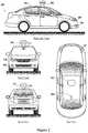
- FIG. 2depicts exterior views of the autonomous vehicle.
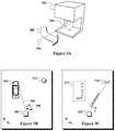
- FIG. 3Aprovides an example depiction of a LIDAR device including beam steering optics.
- FIG. 3Bsymbolically illustrates a LIDAR device scanning across an obstacle-filled environmental scene.
- FIG. 3Csymbolically illustrates a point cloud corresponding to the obstacle-filled environmental scene of FIG. 3B .
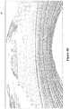
- FIG. 4Bis a rendering of a LIDAR-indicated point cloud corresponding to the scene pictured in FIG. 4A .
- FIG. 4Dis a rendering of a LIDAR-indicated point cloud corresponding to the scene pictured in FIG. 4C .
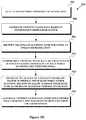
- FIG. 5Ais a flowchart of a process for adaptively adjusting an angular resolution of a LIDAR device by adjusting a pulse rate of the LIDAR device.
- FIG. 5Bis a flowchart of a process for driving a LIDAR device at a pulse rate exceeding a maximum sustained pulse rate for thermally stable operation.
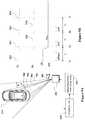
- FIG. 6Asymbolically illustrates a LIDAR device scanning across an example obstacle-filled environmental scene with constant time delays between successive measurement points where the time delays are exaggerated for illustrative purposes.
- FIG. 6Csymbolically illustrates a LIDAR device scanning across the example obstacle-filled environmental scene shown with adaptively adjusted time delays between successive measurement points to provide enhanced angular resolution in the vicinity of the environmental obstacle where the time delays are exaggerated for illustrative purposes.
- FIG. 6Dis a timing diagram of the transmitted and received pulses for the exaggerated symbolic illustration of FIG. 6C .
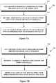
- FIG. 7Ais a flowchart of a process for identifying regions of a LIDAR-indicated point cloud to examine with enhanced angular resolution by detecting edge(s).
- FIG. 7Bis a flowchart of another process for identifying regions of a LIDAR-indicated point cloud to examine with enhanced angular resolution by detecting moving objects.
- FIG. 7Cis a flowchart of another process for identifying regions of a LIDAR-indicated point cloud to examine with enhanced angular resolution by comparison with a baseline point map
- FIG. 7Dis a flowchart of another process for identifying regions of a LIDAR-indicated point cloud to examine with enhanced angular resolution by detecting features beyond a threshold distance.
- FIG. 7Eis a flowchart of another process for identifying regions of a LIDAR-indicated point cloud to examine with enhanced angular resolution by detecting a discontinuity during a scan corresponding to an object edge.
- FIG. 7Fis a flowchart of another process for identifying regions of a LIDAR-indicated point cloud to examine with enhanced angular resolution by identifying features arranged with high spatial or temporal frequency.
- FIG. 7Gis a flowchart of another process for identifying regions of a LIDAR-indicated point cloud to examine with enhanced angular resolution by detecting features that lack sufficient detail for accurate categorization or identification.
- FIG. 8is a flowchart of a process for adaptively adjusting an angular resolution of a LIDAR device by adjusting a slew rate of the LIDAR device.
- FIG. 9Bis a timing diagram of the transmitted and received pulses for the exaggerated symbolic illustration of FIG. 9A .
- FIG. 10is a flowchart of a process for generating a point cloud with variable angular resolution by use of a second LIDAR device with enhanced angular resolution.
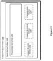
- FIG. 12depicts a computer-readable medium configured according to an example embodiment.
- Example embodimentsrelate to an autonomous vehicle, such as a driverless automobile, that includes a light detection and ranging (LIDAR) sensor for actively detecting reflective features in the environment surrounding the vehicle.
- a controlleranalyzes information from the LIDAR sensor to identify the surroundings of the vehicle and determines how to direct the propulsion systems of the vehicle to affect a navigation path that substantially avoids obstacles indicated by the information from the LIDAR sensor.
- LIDARlight detection and ranging
- the angular resolution of the LIDAR sensoris adjusted to provide enhanced angular resolution scanning in identified regions of an environmental scene.
- the LIDAR deviceoperates by scanning a pulsing laser across a scanning zone, and measuring the time delays until reception of corresponding reflected pulses. The orientation of the LIDAR device for each pulse is combined with the measured time delay to determine the position of the environmental feature responsible for reflecting the pulse. Combining many such points provides a three-dimensional point cloud representing the environmental scene surrounding the vehicle.
- the pulsing lasercan be scanned by directing the laser with optical beam steering optics, such as a rotating angled mirror that directs a fixed laser source according to the angle of the mirror.
- Some embodiments of the present disclosureprovide for adjusting the angular resolution of such a scanning LIDAR system by adjusting one or both of: (1) a pulse rate of the pulsing laser, or (2) an angular rate of change of the beam steering optics. Modifying one or both of the angular rate of change or the pulse rate modifies the amount of angular change between each successive pulse emitted from the LIDAR sensor, and thereby modifies the angular resolution of the point cloud output from the LIDAR system.
- a second LIDAR deviceprovides high resolution scanning of regions identified according to point cloud information from a first LIDAR device providing wide-view scanning resolutions.
- Regions to scan with enhanced angular resolutioncan be automatically identified by analyzing the point cloud information from one or more previous scans and/or the current scan.
- data from one or more previously detected point mapsare analyzed to identify regions of the scene that include edges of perceived objects.
- the next scancan then selectively provide enhanced angular resolution near the edges so as to better define the boundaries of the perceived feature while maintaining standard resolution, or even decreased resolution, in the regions between the edges.
- an enhanced resolution regioncan be indicated by identifying a feature in motion, a feature not present in a baseline map of the scene, or a distant feature.
- enhanced resolution scanningcan be initiated before completing a full scan on the basis of a partial point map that includes a discontinuity indicative of an edge of a reflective environmental feature.
- the spatial resolution of a LIDAR-generated 3-D point mapdepends on the physical separation between points, which is a function of both the distance to the points and the angular separation between the points, with respect to the LIDAR. For example, smaller angular separation between measured points provides higher spatial resolution for a given distance, and vice versa. Similarly, smaller distances result in higher spatial resolution for a given angular separation, and vice versa.
- the angular separation between pointsis sometimes referred to as the “density” of points, whereby higher density generally corresponds to higher spatial resolution, and vice versa.
- Some embodiments of the present disclosurealso provide for achieving enhanced angular resolution in a LIDAR system by driving a pulsing laser at a pulse rate that exceeds a maximum sustained pulse rate associated with thermally stable device operation.
- the maximum sustained thermally stable pulse rateis determined according to thermal device behavior such as heat dissipation characteristics, heat generation in laser components, temperature-dependent behavior of associated optical components, etc.
- Lasers employed in LIDAR systemstherefore have a device-specific maximum sustained pulse rate that allows the device to continuously operate without experiencing adverse thermal effects. In some examples, however, the maximum sustained pulse rate can be temporarily exceeded if followed by a corresponding decrease in pulse rate such that the average pulse rate of the laser system does not exceed the maximum sustained rate.
- the maximum theoretical angular resolution of the systemis determined by the refresh rate (number of complete scans to be completed per second), the total solid angle scanned during each complete scan, and the maximum sustained pulse rate.
- ⁇ totis the total solid angle scanned during each scan
- the total pulses per scanis a function of the maximum sustained pulse rate and the refresh rate.
- the total pulses per scancan be given by f thermal /f refresh , where f thermal is the maximum sustained pulse rate, and f refresh is the refresh rate of the LIDAR system.
- the refresh rate for the LIDARis set to provide high-resolution, real-time 3-D point maps on a time scale that is relevant to navigation decisions, such as adjustments to propulsion systems of the autonomous vehicle in real time.
- the refresh ratemay be dependent on the vehicle's rate of speed. For example, the refresh rate may be higher at high rates of speeds, because at high speeds potential obstacles (and the need to maneuver around them) tend to develop on relatively short time scales for a potential obstacle at a fixed distance. On the other hand, the refresh rate may be lower at low rates of speed, because at low speeds potential obstacles (and the need to maneuver around them) tend to develop on relatively greater time scales.
- An example systemmay be implemented in, or may take the form of, an automobile.
- an example systemmay also be implemented in or take the form of other vehicles, such as cars, trucks, motorcycles, buses, boats, airplanes, helicopters, lawn mowers, earth movers, boats, snowmobiles, aircraft, recreational vehicles, amusement park vehicles, farm equipment, construction equipment, trams, golf carts, trains, and trolleys.
- Other vehiclesare possible as well.
- FIG. 1is a functional block diagram illustrating a vehicle 100 according to an example embodiment.
- the vehicle 100is configured to operate fully or partially in an autonomous mode, and thus may be referred to as an “autonomous vehicle.”
- a computer system 112can control the vehicle 100 while in an autonomous mode via control instructions to a control system 106 for the vehicle 100 .
- the computer system 112can receive information from one or more sensor systems 104 , and base one or more control processes (such as the setting a heading so as to avoid a detected obstacle) upon the received information in an automated fashion.
- the vehicle 100includes a propulsion system 102 , a sensor system 104 , a control system 106 , one or more peripherals 108 , a power supply 110 , a computer system 112 , and a user interface 116 .
- the vehicle 100may include more or fewer subsystems and each subsystem can optionally include multiple components. Further, each of the subsystems and components of vehicle 100 can be interconnected and/or in communication. Thus, one or more of the functions of the vehicle 100 described herein can optionally be divided between additional functional or physical components, or combined into fewer functional or physical components. In some further examples, additional functional and/or physical components may be added to the examples illustrated by FIG. 1 .
- the propulsion system 102can include components operable to provide powered motion to the vehicle 100 .
- the propulsion system 102includes an engine/motor 118 , an energy source 119 , a transmission 120 , and wheels/tires 121 .
- the engine/motor 118converts energy source 119 to mechanical energy.
- the propulsion system 102can optionally include one or both of engines and/or motors.
- a gas-electric hybrid vehiclecan include both a gasoline/diesel engine and an electric motor.
- the transmission 120includes appropriate gears and/or mechanical elements suitable to convey the mechanical power from the engine/motor 118 to the wheels/tires 121 .
- the transmission 120includes a gearbox, a clutch, a differential, a drive shaft, and/or axle(s), etc.
- the wheels/tires 121are arranged to stably support the vehicle 100 while providing frictional traction with a surface, such as a road, upon which the vehicle 100 moves. Accordingly, the wheels/tires 121 are configured and arranged according to the nature of the vehicle 100 .
- the wheels/tirescan be arranged as a unicycle, bicycle, motorcycle, tricycle, or car/truck four-wheel format. Other wheel/tire geometries are possible, such as those including six or more wheels. Any combination of the wheels/tires 121 of vehicle 100 may be operable to rotate differentially with respect to other wheels/tires 121 .
- the wheels/tires 121can optionally include at least one wheel that is rigidly attached to the transmission 120 and at least one tire coupled to a rim of a corresponding wheel that makes contact with a driving surface.
- the wheels/tires 121may include any combination of metal and rubber, and/or other materials or combination of materials.
- the sensor system 104generally includes one or more sensors configured to detect information about the environment surrounding the vehicle 100 .
- the sensor system 104can include a Global Positioning System (GPS) 122 , an inertial measurement unit (IMU) 124 , a RADAR unit 126 , a laser rangefinder/LIDAR unit 128 , a camera 130 , and/or a microphone 131 .
- the sensor system 104could also include sensors configured to monitor internal systems of the vehicle 100 (e.g., O 2 monitor, fuel gauge, engine oil temperature, wheel speed sensors, etc.).
- One or more of the sensors included in sensor system 104could be configured to be actuated separately and/or collectively in order to modify a position and/or an orientation of the one or more sensors.
- the GPS 122is a sensor configured to estimate a geographic location of the vehicle 100 .
- GPS 122can include a transceiver operable to provide information regarding the position of the vehicle 100 with respect to the Earth.
- the IMU 124can include any combination of sensors (e.g., accelerometers and gyroscopes) configured to sense position and orientation changes of the vehicle 100 based on inertial acceleration.
- sensorse.g., accelerometers and gyroscopes
- the RADAR unit 126can represent a system that utilizes radio signals to sense objects within the local environment of the vehicle 100 .
- the RADAR unit 126 and/or the computer system 112can additionally be configured to sense the speed and/or heading of the objects.
- the laser rangefinder or LIDAR unit 128can be any sensor configured to sense objects in the environment in which the vehicle 100 is located using lasers.
- the laser rangefinder/LIDAR unit 128can include one or more laser sources, a laser scanner, and one or more detectors, among other system components.
- the laser rangefinder/LIDAR unit 128can be configured to operate in a coherent (e.g., using heterodyne detection) or an incoherent detection mode.
- the camera 130can include one or more devices configured to capture a plurality of images of the environment surrounding the vehicle 100 .
- the camera 130can be a still camera or a video camera.
- the camera 130can be mechanically movable such as by rotating and/or tilting a platform to which the camera is mounted. As such, a control process of vehicle 100 may be implemented to control the movement of camera 130 .
- the sensor system 104can also include a microphone 131 .
- the microphone 131can be configured to capture sound from the environment surrounding vehicle 100 .
- multiple microphonescan be arranged as a microphone array, or possibly as multiple microphone arrays.
- the control system 106is configured to control operation(s) regulating acceleration of the vehicle 100 and its components. To effect acceleration, the control system 106 includes a steering unit 132 , throttle 134 , brake unit 136 , a sensor fusion algorithm 138 , a computer vision system 140 , a navigation/pathing system 142 , and/or an obstacle avoidance system 144 , etc.
- the steering unit 132is operable to adjust the heading of vehicle 100 .
- the steering unitcan adjust the axis (or axes) of one or more of the wheels/tires 121 so as to effect turning of the vehicle.
- the throttle 134is configured to control, for instance, the operating speed of the engine/motor 118 and, in turn, adjust forward acceleration of the vehicle 100 via the transmission 120 and wheels/tires 121 .
- the brake unit 136decelerates the vehicle 100 .
- the brake unit 136can use friction to slow the wheels/tires 121 .
- the brake unit 136inductively decelerates the wheels/tires 121 by a regenerative braking process to convert kinetic energy of the wheels/tires 121 to electric current.
- the computer vision system 140can process and analyze images captured by camera 130 to identify objects and/or features in the environment surrounding vehicle 100 .
- the detected features/objectscan include traffic signals, road way boundaries, other vehicles, pedestrians, and/or obstacles, etc.
- the computer vision system 140can optionally employ an object recognition algorithm, a Structure From Motion (SFM) algorithm, video tracking, and/or available computer vision techniques to effect categorization and/or identification of detected features/objects.
- SFMStructure From Motion
- the computer vision system 140can be additionally configured to map the environment, track perceived objects, estimate the speed of objects, etc.
- the obstacle avoidance system 144can represent a control system configured to identify, evaluate, and avoid or otherwise negotiate potential obstacles in the environment surrounding the vehicle 100 .
- the obstacle avoidance system 144can effect changes in the navigation of the vehicle by operating one or more subsystems in the control system 106 to undertake swerving maneuvers, turning maneuvers, braking maneuvers, etc.
- the obstacle avoidance system 144is configured to automatically determine feasible (“available”) obstacle avoidance maneuvers on the basis of surrounding traffic patterns, road conditions, etc.
- availablefeasible
- the obstacle avoidance system 144can be configured such that a swerving maneuver is not undertaken when other sensor systems detect vehicles, construction barriers, other obstacles, etc. in the region adjacent the vehicle that would be swerved into.
- the obstacle avoidance system 144can automatically select the maneuver that is both available and maximizes safety of occupants of the vehicle. For example, the obstacle avoidance system 144 can select an avoidance maneuver predicted to cause the least amount of acceleration in a passenger cabin of the vehicle 100 .
- the vehicle 100also includes peripherals 108 configured to allow interaction between the vehicle 100 and external sensors, other vehicles, other computer systems, and/or a user, such as an occupant of the vehicle 100 .
- the peripherals 108 for receiving information from occupants, external systems, etc.can include a wireless communication system 146 , a touchscreen 148 , a microphone 150 , and/or a speaker 152 .
- An occupant of the vehicle 100can also utilize a voice command interface.
- the microphone 150can be configured to receive audio (e.g., a voice command or other audio input) from a user of the vehicle 100 .
- the speakers 152can be configured to output audio to the user of the vehicle 100 .
- the peripherals 108function to allow communication between the vehicle 100 and external systems, such as devices, sensors, other vehicles, etc. within its surrounding environment and/or controllers, servers, etc., physically located far from the vehicle that provide useful information regarding the vehicle's surroundings, such as traffic information, weather information, etc.
- the wireless communication system 146can wirelessly communicate with one or more devices directly or via a communication network.
- the wireless communication system 146can optionally use 3G cellular communication, such as CDMA, EVDO, GSM/GPRS, and/or 4G cellular communication, such as WiMAX or LTE.
- wireless communication system 146can communicate with a wireless local area network (WLAN), for example, using WiFi.
- WLANwireless local area network
- wireless communication system 146could communicate directly with a device, for example, using an infrared link, Bluetooth, and/or ZigBee.
- the wireless communication system 146can include one or more dedicated short range communication (DSRC) devices that can include public and/or private data communications between vehicles and/or roadside stations.
- DSRCdedicated short range communication
- Other wireless protocols for sending and receiving information embedded in signals, such as various vehicular communication systems,can also be employed by the wireless communication system 146 within the context of the present disclosure.
- the power supply 110can provide power to components of vehicle 100 , such as electronics in the peripherals 108 , computer system 112 , sensor system 104 , etc.
- the power supply 110can include a rechargeable lithium-ion or lead-acid battery for storing and discharging electrical energy to the various powered components, for example.
- one or more banks of batteriescan be configured to provide electrical power.
- the power supply 110 and energy source 119can be implemented together, as in some all-electric cars.
- Computer system 112that receives inputs from the sensor system 104 , peripherals 108 , etc., and communicates appropriate control signals to the propulsion system 102 , control system 106 , peripherals, etc. to effect automatic operation of the vehicle 100 based on its surroundings.
- Computer system 112includes at least one processor 113 (which can include at least one microprocessor) that executes instructions 115 stored in a non-transitory computer readable medium, such as the data storage 114 .
- the computer system 112may also represent a plurality of computing devices that serve to control individual components or subsystems of the vehicle 100 in a distributed fashion.
- data storage 114contains instructions 115 (e.g., program logic) executable by the processor 113 to execute various functions of vehicle 100 , including those described above in connection with FIG. 1 .
- Data storage 114may contain additional instructions as well, including instructions to transmit data to, receive data from, interact with, and/or control one or more of the propulsion system 102 , the sensor system 104 , the control system 106 , and the peripherals 108 .
- the data storage 114may store data such as roadway maps, path information, among other information. Such information may be used by vehicle 100 and computer system 112 during operation of the vehicle 100 in the autonomous, semi-autonomous, and/or manual modes to select available roadways to an ultimate destination, interpret information from the sensor system 104 , etc.
- the vehicle 100provides information to and/or receives input from, a user of vehicle 100 , such as an occupant in a passenger cabin of the vehicle 100 .
- the user interface 116can accordingly include one or more input/output devices within the set of peripherals 108 , such as the wireless communication system 146 , the touchscreen 148 , the microphone 150 , and/or the speaker 152 to allow communication between the computer system 112 and a vehicle occupant.
- the computer system 112controls the operation of the vehicle 100 based on inputs received from various subsystems indicating vehicle and/or environmental conditions (e.g., propulsion system 102 , sensor system 104 , and/or control system 106 ), as well as inputs from the user interface 116 , indicating user preferences.
- the computer system 112can utilize input from the control system 106 to control the steering unit 132 to avoid an obstacle detected by the sensor system 104 and the obstacle avoidance system 144 .
- the computer system 112can be configured to control many aspects of the vehicle 100 and its subsystems. Generally, however, provisions are made for manually overriding automated controller-driven operation, such as in the event of an emergency, or merely in response to a user-activated override, etc.
- the components of vehicle 100 described hereincan be configured to work in an interconnected fashion with other components within or outside their respective systems.
- the camera 130can capture a plurality of images that represent information about an environment of the vehicle 100 while operating in an autonomous mode.
- the environmentmay include other vehicles, traffic lights, traffic signs, road markers, pedestrians, etc.
- the computer vision system 140can categorize and/or recognize various aspects in the environment in concert with the sensor fusion algorithm 138 , the computer system 112 , etc. based on object recognition models pre-stored in data storage 114 , and/or by other techniques.
- vehicle 100is described and shown in FIG. 1 as having various components of vehicle 100 , e.g., wireless communication system 146 , computer system 112 , data storage 114 , and user interface 116 , integrated into the vehicle 100 , one or more of these components can optionally be mounted or associated separately from the vehicle 100 .
- data storage 114can exist, in part or in full, separate from the vehicle 100 , such as in a cloud-based server, for example.
- one or more of the functional elements of the vehicle 100can be implemented in the form of device elements located separately or together.
- the functional device elements that make up vehicle 100can generally be communicatively coupled together in a wired and/or wireless fashion.
- FIG. 2shows an example vehicle 200 that can include all or most of the functions described in connection with vehicle 100 in reference to FIG. 1 .
- vehicle 200is illustrated in FIG. 2 as a four-wheel sedan-type car for illustrative purposes, the present disclosure is not so limited.
- the vehicle 200can represent a truck, a van, a semi-trailer truck, a motorcycle, a golf cart, an off-road vehicle, or a farm vehicle, etc.
- the example vehicle 200includes a sensor unit 202 , a wireless communication system 204 , a LIDAR unit 206 , a laser rangefinder unit 208 , and a camera 210 . Furthermore, the example vehicle 200 can include any of the components described in connection with vehicle 100 of FIG. 1 .
- the sensor unit 202is mounted atop the vehicle 200 and includes one or more sensors configured to detect information about an environment surrounding the vehicle 200 , and output indications of the information.
- sensor unit 202can include any combination of cameras, RADARs, LIDARs, range finders, and acoustic sensors.
- the sensor unit 202can include one or more movable mounts that could be operable to adjust the orientation of one or more sensors in the sensor unit 202 .
- the movable mountcould include a rotating platform that could scan sensors so as to obtain information from each direction around the vehicle 200 .
- the movable mount of the sensor unit 202could be moveable in a scanning fashion within a particular range of angles and/or azimuths.
- the sensor unit 202could be mounted atop the roof of a car, for instance, however other mounting locations are possible. Additionally, the sensors of sensor unit 202 could be distributed in different locations and need not be collocated in a single location. Some possible sensor types and mounting locations include LIDAR unit 206 and laser rangefinder unit 208 . Furthermore, each sensor of sensor unit 202 could be configured to be moved or scanned independently of other sensors of sensor unit 202 .
- the wireless communication system 204could be located on a roof of the vehicle 200 as depicted in FIG. 2 . Alternatively, the wireless communication system 204 could be located, fully or in part, elsewhere.
- the wireless communication system 204may include wireless transmitters and receivers that could be configured to communicate with devices external or internal to the vehicle 200 .
- the wireless communication system 204could include transceivers configured to communicate with other vehicles and/or computing devices, for instance, in a vehicular communication system or a roadway station. Examples of such vehicular communication systems include dedicated short range communications (DSRC), radio frequency identification (RFID), and other proposed communication standards directed towards intelligent transport systems.
- DSRCdedicated short range communications
- RFIDradio frequency identification
- the camera 210can be a photo-sensitive instrument, such as a still camera, a video camera, etc., that is configured to capture a plurality of images of the environment of the vehicle 200 .
- the camera 210can be configured to detect visible light, and can additionally or alternatively be configured to detect light from other portions of the spectrum, such as infrared or ultraviolet light.
- the camera 210can be a two-dimensional detector, and can optionally have a three-dimensional spatial range of sensitivity.
- the camera 210can include, for example, a range detector configured to generate a two-dimensional image indicating distance from the camera 210 to a number of points in the environment. To this end, the camera 210 may use one or more range detecting techniques.
- the camera 210can provide range information by using a structured light technique in which the vehicle 200 illuminates an object in the environment with a predetermined light pattern, such as a grid or checkerboard pattern and uses the camera 210 to detect a reflection of the predetermined light pattern from environmental surroundings. Based on distortions in the reflected light pattern, the vehicle 200 can determine the distance to the points on the object.
- the predetermined light patternmay comprise infrared light, or radiation at other suitable wavelengths for such measurements.
- the camera 210can be mounted inside a front windshield of the vehicle 200 . Specifically, the camera 210 can be situated to capture images from a forward-looking view with respect to the orientation of the vehicle 200 . Other mounting locations and viewing angles of camera 210 can also be used, either inside or outside the vehicle 200 .
- the camera 210can have associated optics operable to provide an adjustable field of view. Further, the camera 210 can be mounted to vehicle 200 with a movable mount to vary a pointing angle of the camera 210 , such as a via a pan/tilt mechanism.
- FIG. 3Aprovides an example depiction of a light detection and ranging (LIDAR) device 302 including beam steering optics 304 .
- a laser beam 306is directed to the beam steering optics 304 .
- the beam steering optics 304is a rotating angled mirror that directs the initially downward facing laser beam 306 to sweep across a scanning zone.
- the beam steering optics 304which can generally be implemented as a combination of lenses, mirrors, and/or apertures configured to direct the laser beam to sweep across a scanning zone, are interchangeably described as the rotating angled mirror 304 .
- the rotating angled mirror 304rotates about an axis substantially parallel, and roughly in line with, the initial downward path of the laser beam 306 .
- the rotating angled mirror 304rotates in the direction indicated by the reference arrow 308 in FIG. 3A .
- rangefinder 302is depicted as having (approximately) a 180 degree range of rotation for the scanning zone of the laser beam 306 via the rotating angled mirror 304 , this is for purposes of example and explanation only, as the present disclosure is not so limited. Indeed, as explained above, LIDAR 302 can be configured to have viewing angle (e.g., angular range of available orientations during each sweep), including viewing angles up to and including 360 degrees. Further, although LIDAR 302 is depicted with the single laser beam 306 and a single mirror 304 , this is for purposes of example and explanation only, as the present disclosure is not so limited. Indeed, as explained above, LIDAR 302 can include multiple laser beams operating simultaneously or sequentially to provide greater sampling coverage of the surrounding environment.
- FIG. 3Bsymbolically illustrates the LIDAR device 302 scanning across an obstacle-filled environmental scene.
- the example vehicular environment depicted in FIG. 3Bincludes a car 310 and a tree 312 .
- LIDAR 302rotates according to motion reference arrow 308 with angular velocity ⁇ . While rotating, the LIDAR 302 regularly (e.g., periodically) emits laser beams, such as the laser beam 306 . Reflections from the emitted laser beams by objects in the environment, such as vehicle 310 and tree 312 , are then received by suitable sensors.
- Precisely time-stamping the receipt of the reflected signalsallows for associating each reflected signal (if any is received at all) with the most recently emitted laser pulse, and measuring the time delay between emission of the laser pulse and reception of the reflected light.
- the time delayprovides an estimate of the distance to the reflective feature by scaling according to the speed of light in the intervening atmosphere.
- Combining the distance information for each reflected signal with the orientation of the LIDAR device 302 for the respective pulse emissionallows for determining a position of the reflective feature in three-dimensions. For illustrative purposes, the environmental scene in FIG.
- 3Bis described in the two-dimensional x-y plane in connection with a single sweep of the LIDAR device 302 that estimates positions to a series of points located in the x-y plane. However, it is noted that a more complete three-dimensional sampling is provided by either adjusting the beam steering optics 304 to direct the laser beam 306 up or down from the x-y plane on its next sweep of the scene or by providing additional lasers and associated beam steering optics dedicated to sampling point locations in planes above and below the x-y plane shown in FIG. 3B , or combinations of these.
- FIG. 3Csymbolically illustrates a point cloud corresponding to the obstacle-filled environmental scene of FIG. 3B .
- Spatial-point data(represented by stars) are shown from a ground-plane (or aerial) perspective. Even though the individual points are not equally spatially distributed throughout the sampled environment, adjacent sampled points are roughly equally angularly spaced with respect to the LIDAR device 302 .
- a car spatial data 314correspond to measured points on the surface of the car 310 with a line of sight to the LIDAR device 302 .
- a tree spatial data 316correspond to measured points on the surface of the tree 312 visible from the LIDAR device 302 . The absence of points between the car spatial data 314 and the tree spatial data 316 indicates an absence of reflective features along the sampled line of sight paths in the plane illustrated.
- Each point in the example point cloud illustrated symbolically in FIG. 3Ccan be referenced by an azimuth angle ⁇ (e.g. orientation of the LIDAR device 302 while emitting the pulse corresponding to the point, which is determined by the orientation of the rotating angled mirror 304 ) and a line-of-sight (LOS) distance (e.g., the distance indicated by the time delay between pulse emission and reflected light reception).
- ⁇azimuth angle
- LOSline-of-sight
- the LOS distancecan optionally be set to the maximum distance sensitivity of the LIDAR device 302 .
- the maximum distance sensitivitycan be determined according to the maximum time delay the associated optical sensors wait for a return reflected signal following each pulse emission, which can itself be set according to the anticipated signal strength of a reflected signal at a particular distance given ambient lighting conditions, intensity of the emitted pulse, predicted reflectivity of environmental features, etc.
- the maximum distancecan be approximately 60 meters, 80 meters, 100 meters, or 150 meters, but other examples are possible for particular configurations of the LIDAR device 302 and associated optical sensors.
- the sensor fusion algorithm 138can interpret the car spatial data 314 alone and/or in combination with additional sensor-indicated information and/or memory-based pattern-matching point clouds and/or baseline maps of the environment to categorize or identify the group of points 314 as corresponding to the car 310 .
- the tree spatial data 316can identified as corresponding to the tree 310 in accordance with a suitable object-detection technique. As described further herein, some embodiments of the present disclosure provide for identifying a region of the point cloud for study with enhanced resolution scanning technique on the basis of the already-sampled spatial-points.
- each spatial pointcan be associated with a respective laser from a set of lasers and a respective timestamp. That is, in an embodiment where the LIDAR 302 includes multiple lasers, each respective received spatial point can be associated with the particular laser that was detected in accordance with the respective received spatial point. Additionally, each respective spatial point can be associated with a respective timestamp (e.g., a time at which laser was emitted or received). In this way, the received spatial points may be organized, identified, or otherwise ordered on a spatial (laser identification) and/or temporal (timestamp) basis. Such an ordering may assist or improve an analysis of the spatial-point data by allowing for organizing the spatial-point data into a meaningful order.
- the camera images 402 , 406 of FIGS. 4A and 4Ccan be captured by the camera 210 of the vehicle 200
- the corresponding point cloud maps 404 , 408 of FIGS. 4B and 4Dcan be captured by the LIDAR sensor 206 .
- a laser point cloud imagemay substantially or approximately correspond to a raw camera image captured by a camera.
- FIGS. 4B and 4Dshow that LIDAR-indicated point cloud maps for the distinct environmental scenes 402 , 406 (i.e., the images in FIGS. 4A and 4C ) result in distinct point maps 404 , 408 which correspond to their respective scenes.
- each “line” depicted in FIGS. 4B and 4Dgenerally corresponds to a series of spatial points collected by a particular, single, laser of LIDAR 206 .
- FIGS. 5A-5B, 7A-7G, 8 and 10each present flowcharts describing processes employed separately or in combination in some embodiments of the present disclosure.
- the methods and processes described hereinare generally described by way of example as being carried out by an autonomous vehicle, such as the autonomous vehicles 100 , 200 described above in connection with FIGS. 1 and 2 .
- the processes described hereincan be carried out by a LIDAR sensor 128 and associated optical sensors (e.g., the sensors 202 on vehicle 200 ) mounted to an autonomous vehicle (e.g., the vehicle 200 ) in communication with a computer system 112 , sensor fusion algorithm module 138 , and/or computer vision system 140 .
- program codecan be stored on any type of computer readable medium (e.g., computer readable storage medium or non-transitory media, such as data storage 114 described above with respect to computer system 112 ), for example, such as a storage device including a disk or hard drive.
- each block of the flowchart 500can represent circuitry that is wired to perform the specific logical functions in the process.
- example vehicle 100includes a LIDAR device 128 .
- LIDAR 128actively captures laser point cloud images using one or more lasers.
- the laser point cloudincludes many points for each pulse emitted from the LIDAR device 128 : reflected signals indicate actual locations of reflective objects, whereas failing to receive reflected signals indicate an absence of sufficiently reflective objects within a particular distance along the line of sight of the laser.
- the total solid angle sampled by each LIDAR deviceor just the total solid angle of the scene, where only one LIDAR device is used), the number of sample points in each point cloud can be determined.
- Some embodimentscan provide point clouds with as many as 50,000 laser-indicated points, 80,000 laser-indicated points, 100,000 laser-indicated points, etc.
- the number of laser-indicated points in each point cloudis a tradeoff between angular resolution on the one hand, and refresh rate on the other hand.
- the LIDAR deviceis driven to provide an angular resolution at a sufficiently high refresh rate to be relevant to real time navigational decisions for an autonomous vehicle.
- the LIDAR 128can be configured to capture one or more laser point clouds of the environmental scene at predetermined time intervals, such as 100 milliseconds (for a refresh rate of 10 frames per second), 33 milliseconds (for a refresh rate of 30 frames per second), 1 millisecond, 1 second, etc.
- Data storage 114 of computer system 112 of vehicle 100can store object-detector software, code, or other program instructions.
- object-detector softwarecan include, or be part of, one or more of the control systems 106 described above, including the sensor fusion algorithm 138 , computer vision system 140 , and/or obstacle avoidance system 144 .
- the object detectormay be any configuration of software and/or hardware configured to perceive features in the environmental scene by categorizing and/or identifying objects based on the laser point clouds captured by the LIDAR 128 and/or based on one or more of the sensors in sensor system 104 .
- Objects indicated by the point cloudmay be, for example, a vehicle, a pedestrian, a road sign, a traffic light, a traffic cone, etc.
- the object detector software and/or modulecan associate arrangements of laser-indicated points with patterns matching objects, environmental features, and/or categories of objects or features.
- the object detectorcan be pre-loaded (or dynamically instructed) to associate arrangements according to one or more parameters corresponding to physical objects/features in the environment surrounding the vehicle 100 .
- the object detectorcan be pre-loaded with information indicating a typical height of a pedestrian, a length of a typical automobile, confidence thresholds for classifying suspected objects, etc.
- the object detectorcan define a bounding box encompassing the object that.
- the bounding boxcan correspond to a predicted exterior surface of the point cloud indicated object.
- the bounding “box”can generally take the form of a multi-sided closed shape defining the predicted outer boundaries of the object.
- positions of perceived objects and their corresponding boundary definitionsare associated with a frame number or frame time.
- similarly shaped objects appearing in roughly similar locations in successive scans of the scenecan be associated with one another to track objects in time.
- the objectcan be associated, for each frame on which the object appears, with a distinct bounding shape defining the dimensional extent of the perceived object.
- Perceived objectscan be tracked as the vehicle 100 travels through its surrounding environment and/or as objects move with respect to the vehicle so as to pass through the scanning zone of the LIDAR 128 . Combining two or more successively captured point clouds can thereby allow for determining translation information for detected objects. Future position predictions can be made for objects with characterized motion profiles, such as by observing acceleration and/or velocity of objects such as cars moving along the roadway with the vehicle 100 to predict the location of the object during a subsequent scan. In some embodiments, objects moving through the air are assumed to move along a trajectory influenced by the force of gravity.
- the vehicle 100can also be in communication with an object-identification server (e.g., via the wireless communication system 146 ).
- the object-identification servercan verify and/or classify objects detected by vehicle 100 using the object detector.
- the object-identification servercan facilitate optimization of one or more of the parameters used by the object detector to detect objects in the captured laser point cloud based on accumulated data from other similar systems, local conditions.
- vehicle 100can communicate the object boundaries, and their corresponding object parameters, to the object identification server for verification that the perceived objects are correctly identified, such as indicated by an evaluation for statistical likelihood of correct identification.
- a single laser in the LIDAR devicecan have a scanning range of approximately 150 meters distance, a thirty degree vertical (“altitude”) field of view, and approximately a thirty degree horizontal (“azimuth”) field of view. Additional lasers included in the LIDAR device can have complementary ranges and fields of view as well so as to provide sufficient coverage of an environmental scene to inform navigational determinations.
- FIG. 5Ais a flowchart 500 of a process for adaptively adjusting an angular resolution of a LIDAR device by adjusting a pulse rate of the LIDAR device.
- a LIDAR sensoris scanned through a scanning zone ( 502 ).
- a LIDAR sensorcan be similar to the LIDAR device 302 described in connection with FIGS. 3A-3C and can be scanned through a scanning zone by manipulating beam steering optics (e.g., the rotating angled mirror 304 ) to direct a pulsing laser to sweep across a scene.
- the scanning zone scanned by the LIDAR sensoris then the complete scene scanned by the pulsing laser.
- scanning the scanning zonecan be carried out by multiple individual LIDAR devices each scanning respective sections of the entire scanning zone, and which sections can optionally be partially overlapping.
- data from the LIDAR sensoris analyzed to generate a three-dimensional (“3-D”) point cloud of positions of detected reflective points defining reflective features in the environment surrounding the vehicle.
- data from the LIDAR sensorcan include correlated lists of orientation of the LIDAR device (e.g., altitude and azimuth angles), to indicate direction to each point, and time delay between emission and reception, to indicate distance to each point.
- the generated point cloudis analyzed to identify region(s) of the environment surrounding the vehicle for study at enhanced angular resolution ( 506 ).
- Example techniques for identifying the region(s) for enhanced resolution studyare discussed further below in connection with the flowcharts in FIGS. 7A-7G
- the region(s)can be identified by an automated process configured to receive point cloud data, analyze one or more frames of point cloud data, and identify regions of the environment indicated by the point cloud data that warrant examination at enhanced angular resolution.
- Such an automated processcan be implemented via hardware modules and/or software components executed via the computer system 112 and processor 114 to provide functions such as pattern recognition, object detection, etc. to analyze the 3-D point clouds.
- the LIDAR sensorWhile scanning the identified region(s), the LIDAR sensor is driven with an increased pulse rate ( 508 ) so as to increase the density of sample points in the identified region(s) and thereby increase the local angular resolution of the point cloud.
- the rate of angular sweeping provided by the beam steering optics 304can be maintained at a constant rate while the pulse rate of the laser source is increased such that the time delay between successively emitted pulses, and similarly the amount of angular change provided by the beam steering optics between successively emitted pulses, is decreased.
- Temporarily increasing the laser pulse rate while scanning the identified region(s)thus provides enhanced angular resolution, with respect to the LIDAR device, in those identified region(s).
- Another 3-D point cloudis generated from the LIDAR-sampled data ( 510 ).
- the point cloud generated in block 510generally has greater angular resolution in the identified region(s), where the pulse rate was increased, than in other regions of the scanning zone such that the resulting 3-D point cloud has a non-uniform angular resolution (e.g., a non-uniform angular separation between adjacent points), with respect to the position of the LIDAR device.
- the non-uniform 3-D point cloud generated in block 510can then be further analyzed by the hardware modules and/or software components, such as the obstacle avoidance systems 144 , computer vision systems 140 , sensor fusion algorithm 138 , object detection systems, etc. to inform autonomous decision-making by the vehicle 100 based on the indications of the surrounding environment provided by the non-uniform 3-D point cloud.
- FIG. 5Bis a flowchart 520 of a process for driving a LIDAR device at a pulse rate temporarily exceeding a maximum sustained thermally stable pulse rate.
- a scanning LIDARe.g., the LIDAR device 302 described in connection with FIGS. 3A-3C
- the pulse intensitye.g., laser brightness
- duty cyclee.g., length of pulse duration as compared to interval between successive pulses
- the intensityis set according to the desired distance sensitivity of the LIDAR device, and the duration is set to be as short as practicable so as to maximize the temporal sensitivity of the time delay measurement.
- the pulse rate of the LIDAR device in continuation operationis desirably selected to avoid undesirable thermally-driven effects in the output signal, such as intensity variations in the laser output, spontaneous optical noise, etc. and/or excessive degradation in the operating lifetime of the device, such as due to sustained operating temperatures above a threshold level, etc.
- Some embodiments of the present disclosureallow for temporarily increasing the pulse rate from a default rate to exceed the maximum sustained pulse rate. To mitigate the thermal limits in the behavior of the device, exceeding the maximum sustained pulse rate is followed by a period of decreased pulse rate to allow the LIDAR device to thermally stabilize before returning to the default pulse rate. In some examples, the period of decreased pulse rate can optionally immediately follow operating in excess of the maximum sustained pulse rate. The default pulse rate can optionally be substantially similar to the maximum sustained pulse rate. Furthermore, some embodiments of the present disclosure allow for temporarily driving a LIDAR device at a rate exceeding a maximum sustained pulse rate when preceded by a period of decreased pulse rate to allow the LIDAR device to cool prior to exceeding the maximum sustained pulse rate. In some embodiments, the total duration of the temporary increase in the pulse rate is less than a characteristic thermal rise time of the LIDAR device itself.
- the scanning LIDARmay be operated at a first pulse rate, such as a default pulse rate, that is within its pulse-rate limit so as to generate in real time a 3-D point cloud with a substantially uniform angular resolution based on the first pulse rate ( 502 , 504 ).
- a processor-based perception systemidentifies region(s) for enhanced resolution examination ( 506 ).
- the pulse rate of the LIDAR deviceis temporarily increased beyond its maximum sustained pulse rate while the LIDAR device scans the identified region(s) ( 522 ).
- the pulse rateis decreased to allow the LIDAR device to thermally regulate ( 524 ).
- the decreased pulse rate in block 524is below the first pulse rate (e.g., default pulse rate) and is maintained for a period long enough to allow the time-averaged pulse rate to be at or below the maximum sustained pulse rate.
- the default pulse rateitself is sufficiently below the maximum sustained pulse rate such that operating at the default pulse rate allows the LIDAR device to sufficiently thermally stabilizes following operation at the excess pulse rate.
- a mixed-resolution 3-D point cloudis generated from the LIDAR-sampled data points, with the high angular resolution regions sampled while the LIDAR device is driven in excess of its maximum sustained pulse rate, and default resolution, and/or low resolution regions sampled while the LIDAR device is driven at its default pulse rate, or low rate, respectively.
- FIG. 6Asymbolically illustrates a LIDAR device 302 scanning across an example obstacle-filled environmental scene with constant time delays (e.g., the delay time t1) between successive measurement points where the time delays are exaggerated for illustrative purposes.
- the LIDAR device 302scans the laser beam 306 across the environmental scene via its beam steering optics 304 while its laser light source pulses, such that successive pulses are emitted with an angular separation ⁇ 1 , which is approximately given by the product of ⁇ and t 1 , where ⁇ is the angular sweeping rate of the LIDAR device (e.g., the angular rotation rate of the beam steering optics 304 ), and t 1 is the time period between successive pulse emissions.
- ⁇is the angular sweeping rate of the LIDAR device (e.g., the angular rotation rate of the beam steering optics 304 )
- t 1is the time period between successive pulse emissions.
- temporally separated pulsese.g., pulses emitted at times separated by the time t 1
- the time scale of the interval between successive pulses, and the corresponding resulting angular separationsis intentionally exaggerated in FIG. 6A for illustrative purposes.
- a controller 630is arranged to receive signals from the LIDAR device 302 and/or associated optical sensors to generate point cloud data 640 indicative of the 3-D positions of reflective features in the environmental scene surrounding the LIDAR device 302 .
- FIG. 6Bis a timing diagram of the transmitted and received pulses for the exaggerated symbolic illustration of FIG. 6A .
- the timing diagramsymbolically illustrates the transmitted pulses (labeled on FIG. 6B as “Tx”), the received pulses (labeled on FIG. 6B as “Rx”), and the angular sweeping rate of the LIDAR device 302 (labeled on FIG. 6B as ⁇ (t)).
- a first pulse 610 ais emitted from the LIDAR device 302 and directed along laser beam path 306 a via the beam steering optics.
- the beam path 306 ais reflected from near the front passenger-side region of the car 310 , and a first reflected signal 620 a is detected at optical signals associated with the LIDAR device 302 (e.g., via optical sensors included in the sensor system 202 mounted on the vehicle 200 in FIG. 2 ).
- the time delay between the emission of pulse 610 a and reception of the reflected signal 620 ais indicated by time delay ⁇ Ta.
- the time delay ⁇ Ta and the orientation of the LIDAR device 302 at time Ta, i.e., the direction of laser beam 306 aare combined in the controller 630 to map the 3-D position of the reflective point on the front passenger-side region of the car 310 .
- Time Tbwhich a second pulse 610 b is emitted from the LIDAR device 302 and directed along laser beam path 306 b .
- Time Tbis temporally separated from time Ta by the interval time t1, and the direction of the laser beam path 306 b is thus angularly separated from the direction of laser beam path 306 a by angular separation ⁇ 1 , due to the change in orientation of the beam steering optics in the LIDAR device during the interval t 1 .
- the angle of separation ⁇ 1 between the laser beams 306 a and 306 bis at least approximately given by the product of ⁇ 0 and t 1 .
- the laser pulse 310 bis reflected from near the rear passenger-side region of the car 310 , and a second reflected signal 620 b is detected with a relative time delay ⁇ Tb from the emission of the second pulse 610 b . As illustrated in FIG.
- the LIDAR device 302is generally situated behind the car 310 , and so the reflective point near the rear passenger-side region of the car 310 (responsible for the reflected signal 620 b ) is closer to the LIDAR device 302 than the reflective point near the front passenger-side region of the car 310 (responsible for the reflected signal 620 a ).
- the relative time delay ⁇ Tbis shorter than the relative time delay ⁇ Ta, corresponding to the difference in roundtrip travel time at the speed of light between the LIDAR device 302 , and the respective reflective points at the front and rear of the car.
- the sensors detecting the reflected signalscan optionally be sensitive to the intensity of the reflected signals.
- the intensity of the reflected signal 620 bcan be perceptibly greater than the intensity of the reflected signal 620 a , as shown symbolically in FIG. 6B .
- the controller 630maps the 3-D position of the reflective point near the rear passenger-side of the car 310 according to the time delay value ⁇ Tb and the orientation of the LIDAR device 310 at time Tb, i.e., the direction of laser beam 306 b .
- the intensity of the reflected signalcan also indicate the reflectance of the reflective point, in combination with the distance to the point as indicated by the measured time delay.
- the reflectance of the reflective pointcan be employed by software and/or hardware implemented modules in the controller 630 to characterize the reflective features in the environment. For example, traffic indicators such as lane markers, traffic signs, traffic signals, navigational signage, etc., can be indicated in part based on having a relatively high reflectance value, such as associated with a reflective coating applied to traffic and/or navigational signage.
- identifying a relatively high reflectance featurecan provide a prompt to undertake a further scan of the high reflectance feature with one or more sensors, such as those in the sensing system 104 .
- a reflected signal indicating a high reflectance featurecan provide a prompt to image the high reflectance feature with a camera to allow for identifying the high reflectance feature.
- the camera imagecan allow for reading the sign via character recognition and/or pattern matching, etc. and then optionally adjusting navigational instructions based on the sign (e.g., a sign indicating a construction zone, pedestrian crosswalk, school zone, etc. can prompt the autonomous vehicle to reduce speed).
- the signe.g., a sign indicating a construction zone, pedestrian crosswalk, school zone, etc. can prompt the autonomous vehicle to reduce speed.
- a third pulse 610 cis emitted from the LIDAR device 302 .
- the third pulse 610 cis directed along a laser beam path 306 c , which is approximately angularly separated from the beam path 306 b by the angle ⁇ j .
- the pulse 610 cis reflected from a point near the middle of the rear bumper region of the car 310 , and a resulting reflected signal 620 c is detected at the LIDAR device 302 (or its associated optical sensors).
- the controller 630combines the relative time delay ⁇ Tc between the emission of pulse 610 c and reception of reflected signal 620 c and the orientation of the LIDAR device 302 at time Tc, i.e., the direction of beam path 306 c , to map the 3-D position of the reflective point.
- a fourth pulse 610 dis emitted from the LIDAR device 302 .
- the fourth pulse 610 dis directed along a laser beam path 306 d , which is approximately angularly separated from the beam path 306 c by the angle ⁇ j .
- the beam path 306 dentirely avoids the car 310 , and all other reflective environmental features within a maximum distance sensitivity of the LIDAR device 302 .
- the maximum distance sensitivity of the LIDAR device 302is determined by the sensitivity of the associated optical sensors for detecting reflected signals.
- the maximum relative time delay ⁇ Tmaxcorresponds to the maximum distance sensitivity of the LIDAR device (i.e., the time for light signals to make a round trip of the maximum distance).
- the controller 630determines that no reflective features are present in the surrounding environment along the laser beam path 306 d.
- the reflective points on the car 310 corresponding to the reflected signals 610 a - cform a subset of points included in a 3-D point cloud map of the environment surrounding the LIDAR device 302 .
- the direction of the laser beam 310 dis noted in the 3-D point cloud map 640 as being absent of reflective features along the line of sight within the maximum distance sensitivity of the LIDAR device 302 , because no reflected signal was received after the duration ⁇ Tmax following the emission of pulse 610 d at time Td.
- the points corresponding to laser beam directions 306 a - dare combined with points spaced throughout the scanning zone (e.g., the region scanned by the LIDAR device 302 ), to create a complete 3-D point cloud map, and the results are output as fixed resolution point cloud data 640 for further analysis by object detection systems, pattern recognition systems, computer vision systems, etc.
- the points in the generated point cloudare separated by a substantially constant angular separation ⁇ 1 with respect to the LIDAR device 302 due to the substantially constant angular sweeping rate ⁇ 0 and the regular pulse rate of the LIDAR device 302 with interval timing t 1 .
- FIG. 6Csymbolically illustrates the LIDAR device 302 scanning across the example obstacle-filled environmental scene shown with adaptively adjusted time delays between successive measurement points to provide enhanced angular resolution in the vicinity of the environmental obstacle where the time delays are exaggerated for illustrative purposes.
- the LIDAR device 302is operated to scan through the surrounding scene with angular rate of change ⁇ 0 , as in FIG. 6A .
- the pulse rate of the LIDAR device 302is dynamically adjusted to vary from a pulse rate with intervals of approximately t 1 to intervals of approximately t 2 , where t 2 is less than t 1 .
- the LIDAR device 302While operated at the high pulse rate (with intervals between successive pulse emissions of t 2 , rather than t 1 ), the LIDAR device 302 provides angular separations between successive points of ⁇ 2 , given approximately by the product of ⁇ 0 and t 2 .
- the angular resolution of the resulting point cloud(e.g., as determined by the angular separation of adjacent points in the generated point cloud) is modified according to the interval spacing between subsequent pulses.
- the pulse rate of the LIDAR device 302is set to go high while the LIDAR device is directed toward the car 310 .
- the determination to sample at high frequency while directed to the car 310can optionally be determined, at least in part, based on analysis of one or more previous point clouds sampled with fixed angular resolution, such as described in connection with FIGS. 6A and 6B above.
- the region of the environmental scene responsible for generating the reflected signals 620 a - ccan be selected for high resolution examination in a subsequent scan.
- FIGS. 7A-7GDetailed discussions of techniques for identifying regions of an environmental scene for examination at enhanced (“increased”) angular resolution are presented below in connection with FIGS. 7A-7G .
- FIG. 6Dis a timing diagram of the transmitted and received pulses for the exaggerated symbolic illustration of FIG. 6C . Similar to the timing diagram in FIG. 6B , the timing diagram symbolically illustrates the transmitted pulses (labeled on FIG. 6D as “Tx”), the received pulses (labeled on FIG. 6D as “Rx”), and the angular sweeping rate of the LIDAR device 302 (labeled on FIG. 6D as ⁇ (t)).
- a first pulse 610 eis emitted from the LIDAR device 302 at time Te, and directed along laser beam 306 e .
- No reflected signalis detected during the period ⁇ Tmax following the time Te.
- An indication of an absence of reflective features within the maximum distance of sensitivityis noted by the controller 630 in connection with the orientation of the LIDAR device 302 at time Te (i.e., the direction of laser beam 306 e ).
- a second pulse 610 fis emitted from the LIDAR device 302 .
- the second pulse 610 fis directed along a laser beam 306 f , which is oriented with an angular separation ⁇ 1 from the laser beam 306 e .
- the second pulse 610 freaches the front passenger-side region of the car 310 resulting in a reflected signal 620 f .
- the reflected signal 620 fis detected by the LIDAR device 302 and/or its associated optical sensors with a relative time delay of ⁇ Tf following the emission at time Tf.
- the pulse 610 fmarks the beginning of a temporary high pulse rate operation of the LIDAR device 302 .
- the third pulse 610 gis emitted at time Tg, which follows time Tf by an interval t 2 , which interval is less than the interval t 1 between successive pulses while the LIDAR device 302 operates at its default pulse rate.
- the third pulse 610 gis directed along laser beam path 306 g , which has an orientation that differs from the direction of beam path 306 f by the angle ⁇ 2 .
- the angular separation ⁇ 2 between the two beam paths 306 f and 306 gis due, at least in part, to the angular rotation of beam steering optics in the LIDAR device 302 (e.g., the rotating angled mirror 304 of FIG. 3A ) during the interval t 2 .
- the angle ⁇ 2is given approximately by the product of ⁇ 0 and t 2 .
- the third pulse 610 gis reflected from a point near the passenger-side door of the car 310 , and a corresponding reflected signal 620 g is detected by the LIDAR device 302 with relative time delay ⁇ Tg.
- the high rate scanningcontinues through the region including the vehicle 310 , beginning with pulse 610 h emitted along laser beam path 306 h , such that the angular resolution of the generated point cloud for points on and/or near the vehicle 310 is generally greater than regions scanned with the default pulse rate. That is, angular separation between points on or near the car 310 is approximately ⁇ 2 , while the angular separation of points in the point map located elsewhere is approximately ⁇ 1 , and ⁇ 2 is less than ⁇ 1 .
- the high resolution (“high pulse rate”) scanningcan continue until a pulse (or series of repeated pulses) is emitted that does not result in a reflected response signal, which can be interpreted as scanning past a reflective feature of interest.
- the controller 630receives information from the LIDAR device 302 to generate a 3-D point cloud map indicating the locations of reflective features and/or the absence of reflective features within a maximum distance of sensitivity.
- the angular resolution of the distribution of points in the generated point cloudis non-uniform, with respect to the LIDAR device 302 .
- some regions of the environmentare sampled at a high pulse rate, and corresponding high angular resolution (e.g., the region including the car 310 sampled with pulses 306 f - h , etc.), whereas other regions are sampled at the default pulse rate.
- some embodiments described hereindescribe the generated point cloud map as a mixed resolution point cloud.
- Data indicative of the positions of points in the point cloud mapare output as mixed resolution point cloud data 642 .
- the operation described in connection with FIGS. 6A and 6B to generate the fixed resolution point cloud data 640can correspond to the blocks 502 and 504 of the flowchart 500 in FIG. 5A of the process for adaptively adjusting the pulse rate timing to generate a point cloud with non-uniform angular resolution.
- the operation described in connection with FIGS. 6C and 6D to generate the mixed resolution point cloud data 642can correspond to the blocks 508 and 510 of the flowchart 500 in FIG. 5A .
- the processes for identifying regions of a LIDAR-indicated scene for enhanced resolution examination described below in connection with the flowcharts shown in FIGS. 7A-7Gprovide example processes for implementing block 506 of the flowchart 500 in FIG. 5A .
- a region of a LIDAR-indicated point cloudcan be identified for enhanced angular resolution analysis based on a combination of factors.
- enhanced angular resolution analysiscan be initiated in response to identifying factors in one or more of the point cloud distance map provided by the LIDAR device, the intensity map of reflected light (e.g., from the LIDAR-received reflected light signals), an estimate of the location of the autonomous vehicle and/or pre-mapped objects of interest, an output from additional sensors such as the camera 210 , etc.
- the estimated location of the autonomous vehicle and/or objects of interestcan be based on comparing the dynamically generated 3-D point map with a baseline map of the scanning zone showing fixed objects of interests (e.g., lane markers, intersection locations, etc.).
- FIG. 7Ais a flowchart 710 of a process for identifying regions of a LIDAR-indicated point cloud to examine with enhanced angular resolution by detecting edge(s).
- One or more point clouds from previous scans of a scanning zoneare analyzed ( 712 ).
- the analysiscan be carried out via hardware and/or software components, such as the computer system 112 and associated processor 114 , the computer vision system 140 , and/or sensor fusion algorithm module 138 referred to in FIG. 1 in connection with the vehicle 100 .
- An object detection module and/or software moduleidentifies a reflective feature in the scanning zone indicated by the point cloud data ( 714 ).
- Locating edge(s) ( 716 )can include estimating the dimensional extent of identified objects as indicated point cloud groupings in one or more previous scans of the environmental scene, which previous scans can be entirely default angular resolution scans and/or mixed resolution scans.
- edge locationscan be estimated ( 716 ) according to detected discontinuities in distance measurements for adjacent or nearby points in the generated point cloud. That is, in some examples a cluster (“group”) of points in a point cloud approximately define a surface associated with an environmental physical object or fixed feature. Hardware and/or software implemented object detection and/or recognition modules can associate the cluster of points with environmental objects/features. In such an example, the surface defined by the point cluster is surrounded, at least partially, by points that are not part of a continuous surface including the point cluster.
- the edges of viewable portions of perceived objectscan be indicated by a sudden increase in line-of-sight distance where a relatively distant background is visible along a line of sight from the LIDAR device 302 immediately adjacent the perceived object. Additionally or alternatively, the edges of viewable portions of some objects can be indicated by a sudden decrease in line-of-sight distance where a closer object interferes with viewing the entire object.
- edge locationsare estimated ( 716 ) according to predicted object dimensions, as indicated by standard libraries of, for example, car dimensions, pedestrian heights, etc. objects are locate edges of detected objects or features indicated by the generated point cloud data ( 714 ). The location of the edges in the environmental scene can then be based on predicted locations of edge(s) of perceived objects, as informed by standard dimension libraries, even where the perception and/or identification of a particular object is based on only a portion of the object.
- FIG. 7Bis a flowchart of another process for identifying regions of a LIDAR-indicated point cloud to examine with enhanced angular resolution by detecting moving objects.
- One or more previous scans of a scanning zoneare analyzed ( 712 ).
- perceived objects in each generated point cloudare associated with a boundary approximately defining a shape of the perceived objects.
- Objects appearing in more than one frame of a time series of generated point cloudsare associated with one another based on similar point cloud shapes and/or absolute relative positions from one frame to the next. Thus, the same object can be identified and position mapped at a series of time points so as to determine a motion profile of the object.
- an object in motioncan be identified from the point cloud data ( 724 ).
- moving objectscan be distinguished from non-moving objects.
- the locations of such moving objects during the next scancan be predicted, and the predicted location can be set as the region for enhanced resolution study ( 726 ).
- the region set for enhanced resolution study during block 726includes a characteristic uncertainty in the future position of the moving object.
- the region for enhanced resolution studycan therefore be larger than the predicted size of the moving object as determined by the point cloud data.
- the region for enhanced studycan include the predicted location of the moving object during the next scan, and can be enlarged, relative to the size of the moving object, according to the uncertainty of the predicted location.
- the uncertaintycan be formulaic, such as based on the expected size of the moving object, or a standard angular separation surrounding the position of the moving object. Additionally or alternatively, the uncertainty can be based on empirical factors and/or measurement uncertainty in the position and/or motion profile of the moving object, for example.
- the car 310 described in connection with FIG. 6Ccan be in motion with respect to the LIDAR device 302 . That is, the relative position of the car 310 with respect to the LIDAR device 302 can vary between a first scan (e.g., the fixed resolution scan described in connection with FIGS. 6A and 6B ) and a second, high angular resolution scan.
- identifying the region of the environment to scan that includes the car 310 during the second scanincludes predicting a future location of the car 310 based on a motion profile (e.g., speed and direction) for the car 310 .
- a motion profilee.g., speed and direction
- Some embodimentsalso allow for detecting and characterizing moving objects based on real time analysis of a single three-dimensional point cloud map. For example, due to time delays between measuring points in different regions of the scanning zone, there may be some detectable motion of perceived objects within a single frame.
- the scanning zoneis analogous to an arrangement of points distributed in azimuth and elevation, to form a grid-like structure, with each row having a common altitude orientation, and each column having a common azimuth orientation.
- a LIDAR deviceoperates by rotating at a fixed altitude orientation to sample azimuthal variations before moving to the next altitude value
- the relative time delay between scans at distinct altitude valuescan be comparable to the period for a complete scan.
- the “vertical” edges of objectsi.e., edges with approximately instantaneously constant azimuth
- generation of a real-time 3-D point mapcan be used to detect and measure relative motion between the scanning LIDAR and a transient object in the scanning zone ( 724 ).
- hardware and/or software elements of the perception systemcan also predict a trajectory of the moving object.
- the perception systemalso predicts the future location of the moving object, and thereby identifies the regions of the scanning zone for high resolution mapping as a function of time ( 726 ).
- Some embodiments of the present disclosureinclude selectively scanning moving objects with high angular resolution so as to better characterize the position and/or motion profile of such objects. Establishing accurate positions of moving objects allows for precisely characterizing the motion profile of the object over time such that the location of the object can be predicted with greater accuracy than possible without enhanced angular resolution analysis. Thus, some embodiments of the present disclosure operate to selectively allocate scanning resources to resolving the positions and/or motion profiles of moving objects in the scanning zone so as to enable greater precision in future predicted locations of such objects, and thereby enable greater precision in object avoidance.
- the techniques for identifying locations to scan with high angular resolution described in connection with FIGS. 7A and 7Bcan be combined together.
- the region to scan with high angular resolutioncan be the predicted location of edge(s) of a moving object.
- FIG. 7Cis a flowchart of another process for identifying regions of a LIDAR-indicated point cloud to examine with enhanced angular resolution by comparison with a baseline point map.
- a baseline point mapcan be, for example, a three-dimensional map of fixed structures along a roadway that is generated in advance. Such a baseline map can indicate, for example, the approximate three-dimensional locations of curbs, trees, buildings, road signs, permanent barricades, and/or other substantially permanent objects and environmental features defining the surroundings of a roadway or other vehicular path of travel.
- the baseline 3-D mapis generated by a LIDAR device actively monitoring a scene while traversing the scene substantially in the absence of transient objects.
- the baseline 3-D mapcan be generated by combining multiple maps to distinguish fixed features from transient objects. Additionally or alternatively, the baseline 3-D point map can be generated via recognition/categorization software and/or hardware implemented modules that analyze one or more maps to selectively eliminate reflective features identified as corresponding to transient objects, such as reflective features identified as cars, pedestrians, etc.
- the baseline 3-D mapcan be loaded in digital form and stored locally in the data storage 114 of the computer system 112 and/or can be dynamically downloaded from an external server via the communication system 146 .
- One or more LIDAR-indicated point cloud maps of the scanning zoneare analyzed via the hardware and/or software implemented data analysis modules to identify regions for high resolution study ( 712 ). Based on the approximate position of the scanning zone, which can be based on the sensing system 104 , such as the GPS 122 , a region of the baseline map is identified that corresponds to the scanning zone (e.g., a region of the baseline map at substantially the same geographic location as the scanning zone). The dynamically generated 3-D point cloud maps are compared with the corresponding region of the baseline map ( 734 ). The software and/or hardware implemented perception systems identify differences between the dynamically generated point cloud map(s) ( 736 ).
- Reflective features indicated in the dynamically generated pointcould map(s) that are not present in the baseline map are set for enhanced resolution scanning. That is, the region identified for enhanced resolution scanning in block 506 of FIG. 5A is set to include the locations of reflective features indicated by the real time point cloud scans, but not indicated by the baseline 3-D map.
- reflective features indicated in the dynamically generated point cloud maps that are determined to also be present in the baseline mapare identified as fixed features, whereas reflective features not present in the baseline map are identified as transient objects. Scanning such dynamically indicated, presumptively transient objects with enhanced angular resolution allows for greater accuracy in position and/or motion profile determinations and thereby allows for greater precision in obstacle avoidance.
- the baseline 3-D mapis analyzed to identify initial regions for low-resolution scanning and/or high-resolution scanning. For example, regions of the baseline 3-D map that indicate the presence of an intersection, a traffic control signal, a railroad crossing, etc. can be prioritized for high resolution scanning at the expense of regions of the baseline 3-D map that indicate blue sky, a body of water, or another region associated with a low probability of causing an obstacle.
- the initial resolutioncan be dynamically varied according to differences with the baseline 3-D map, as described in connection with FIG. 7C , and/or according to any of the processes described in FIGS. 7A-7G .
- FIG. 7Dis a flowchart 740 of another process for identifying regions of a LIDAR-indicated point cloud to examine with enhanced angular resolution by detecting features beyond a threshold distance.
- One or more LIDAR-indicated point cloud maps of the scanning zoneare analyzed via the hardware and/or software implemented data analysis modules to identify regions for high resolution study ( 712 ).
- Perceived objectse.g., clusters of points located at a distance beyond a threshold distance are identified for enhanced resolution study ( 744 ).
- the identified regionis then scanned with an enhanced angular resolution (e.g., by using an increased pulse rate) and an output mixed resolution point cloud is analyzed to better characterize the distant object.
- the threshold distancecan be set according to a desired spatial resolution to allow object identification/categorization with desired reliability.
- the spacing between adjacent points in the point cloudis given, at least approximately, by the arc length distance mapped by the angular change in the LIDAR orientation at the line of sight distance of the mapped features. Because arc length scales with radius (line of sight distance), the spatial resolution achieved by the LIDAR device is inversely proportionate to the line of sight distance to reflective features. Thus, distant objects can have relatively low spatial resolution which prevents accurate object identification/categorization.
- scanning the distant car with enhanced angular resolutionallows the car to be identified and its position and motion to be characterized sooner than otherwise possible, which enables object avoidance and similar functions to be undertaken sooner.
- distant objectscan optionally be identified for enhanced resolution study only when such distant objects are located within a zone including an anticipated direction of travel of the vehicle (e.g., within a zone defined by a cone with an apex at the vehicle and a base oriented toward a heading of the vehicle). For example, distant objects located directly to either side of a moving vehicle are not set for enhanced resolution study whereas distant objects located directly in front of the vehicle are set for enhanced resolution study.
- distant objectsare identified for enhanced resolution study only when such distant objects are located in a region of the environmental scene warranting further study, such as on another roadway. Regions of the scene warranting further study, such as roadways, etc., can be indicated by the sensor system 104 , computer vision system 140 , etc., based on lane lines, curbs, etc.
- FIG. 7Eis a flowchart 750 of another process for identifying regions of a LIDAR-indicated point cloud to examine with enhanced angular resolution by detecting a discontinuity during a scan corresponding to an object edge.
- a dynamically generated point cloudis analyzed by hardware and/or software implemented data analysis modules ( 752 ).
- the technique demonstrated by block 752analyzes data from a partial point cloud that is currently being sampled. Data from the current, partially complete point cloud is analyzed to identify local discontinuities in the distribution of point locations ( 754 ). For example, similar to the discussion of the technique for edge location described in connection with FIG.
- a cluster of pointscan be considered as being approximately located along a 3-D surface that defines an outer boundary of a reflective object with line of sight to the scanning LIDAR.
- the surface defining a single reflective object/featuregenerally bends and curves according to the shape of the object defined, and so is not necessarily planer. However, at the edges of such objects, the line of sight distances measured by the LIDAR device suddenly change from values roughly in the bounding surface to much further or closer distances, without an indication of any gradual bend or transition.
- the LIDAR devicecan be set to perform high angular resolution sampling so as to better define the edge of any such objects ( 756 ).
- the high resolution study ( 756 )can be initiated without involvement the object detection software and/or hardware modules to analyze a complete scan, identify objects in the scan, and then locate edges of those objects.
- the process illustrated by the flowchart 700 in FIG. 7Eallows for rapid initiation of high resolution scanning to study indicated edges in a currently sampled scan, based on partially taken results from the same, current scan.
- FIG. 7Fis a flowchart 760 of another process for identifying regions of a LIDAR-indicated point cloud to examine with enhanced angular resolution by identifying features arranged with high spatial or temporal frequency.
- Hardware and/or software implemented data analysis modulesanalyze LIDAR-indicated point cloud data from present and/or previous scans of a scanning zone ( 762 ). Regions of the scanning zone with relatively high spatial and/or temporal frequencies of reflective features are located ( 764 ). Regions of the scanning zone are selected for enhanced resolution scanning based on the spatial and/or temporal frequency of the reflective features in those regions ( 766 ).
- the regions with highest spatial and/or temporal frequencycan be ranked and the regions with the highest rankings can be selected for enhanced resolution examination up to the available capacity of the LIDAR system for undergoing enhanced resolution study.
- the regions selected for enhanced resolution studycan preferentially select high temporal frequency regions (e.g., regions including moving objects) and select high spatial frequency regions (e.g., regions of the point cloud map including large distance variations, which can indicate object edges) subject to availability of resources, or vice versa.
- some embodimentsinclude combinations of these approaches where an initially selected region is based on the spatial frequency of the selected region, but is only scanned with high angular resolution again, based on an observed change in the spatial frequency of the reflective features in the region.
- the selection of high resolution scanning regions based on relative spatial and/or temporal frequency of the point cloud mapcan be considered a combination of techniques described in connection with the flowcharts 710 , 720 of FIGS. 7A and 7B to select regions including edges or objects in motion.
- High spatial frequency regions of the scanning zoneinclude regions with relatively large differences in distance measures between angularly nearby points, such as due to the discontinuity effects near the edges of perceived objects.
- High temporal frequency regions of the scanning zoneinclude regions with points in the point cloud that vary between successively generated point cloud map frames, such as due to an object in motion that changes position between successive frames of the point cloud map.
- FIG. 7Gis a flowchart 770 of another process for identifying regions of a LIDAR-indicated point cloud to examine with enhanced angular resolution by detecting features that lack sufficient detail for accurate categorization or identification.
- Hardware and/or software implemented data analysis modulesanalyze LIDAR-indicated point cloud data from present and/or previous scans of a scanning zone ( 772 ). Regions of the scanning zone including reflective features that cannot be identified or categorized with sufficient reliability (e.g., as indicated by an estimated probability of accurate identification) are located ( 774 ). Regions of the scanning zone are selected for enhanced resolution scanning based on the indication of unidentified reflective features in those regions ( 776 ). By scanning the unidentified reflective features with enhanced resolution, additional spatial resolution is provided so as to provide additional information with which to identify the reflective feature, and thereby provide a more accurate interpretation of the surrounding environment.
- reflective featurescan be identified by correlating clusters and/or patterns of points in the point cloud with shapes and/or surfaces defining the boundaries of the reflective feature, and cross-referencing the geometry of the shape against a library of geometries associated with possible objects, such as pedestrians, bicycles, cars, motorcycles, construction equipment, bridges, fire hydrants, mail boxes, road signs, trees, animals, combinations of these, etc.
- reflective featuresare not indicated with sufficient spatial resolution, such as for distant objects, it may be too difficult to reliably distinguish, based on LIDAR-indicated point clouds, whether a reflective object is a traffic cone or a fire hydrant.
- LIDAR-indicated point cloudsit may be too difficult to reliably distinguish, based on LIDAR-indicated point clouds, whether a reflective object is a traffic cone or a fire hydrant.
- increasing LIDAR angular resolution in regions where an object is perceived to be located, but cannot be accurately identifiedallows for selectively providing additional information to identify the object.
- the technique of FIG. 7G described in connection with flowchart 770employs the output of the hardware and/or software implemented object detection system as feedback for the operation of the LIDAR system.
- the LIDAR systemthereby selectively allocates its enhanced resolution scanning resources to regions of the scanning zone with insufficient spatial resolution to allow for reliable object detection.
- reliable identification of perceived objectsallows for greater obstacle avoidance.
- identified objectscan be associated with typical motion and/or speed profiles that allow for enhanced prediction of future locations.
- the techniques for identifying regions of a scanning zone for enhanced resolution scanning described in connection with the flowcharts 710 , 720 , 730 , 740 , 750 , 760 , 770 in FIGS. 7A-7Gcan each individually or as a combination of one or more be implemented as block 506 of the flowchart 500 described in connection with FIG. 5A .
- FIG. 8is a flowchart 802 of a process for adaptively adjusting an angular resolution of a LIDAR device by adjusting a slew rate of the LIDAR device. Similar to the process described in connection with the flowchart 500 in FIG. 5A , a LIDAR device is scanned through a scanning zone ( 502 ), a 3-D point cloud data is generated from the LIDAR output ( 504 ), and regions of the point cloud are identified for enhanced resolution study ( 506 ). To provide high angular resolution scanning, however, the slew rate of the beam steering optics of the LIDAR device is selectively slowed while scanning the selected regions ( 808 ). A mixed resolution 3-D point cloud is generated that includes relatively high angular resolution in the identified regions due to the small rate of the change of the beam steering optics while scanning those regions ( 810 ).
- the rotation rate of the angled rotating mirror 304is temporarily slowed such that the relative angular change between successive pulses of the laser is decreased according to the rate of rotation.
- the slew rate of the LIDAR device referred to hereinis the angular rate of change of the orientation of the laser pulses emitted from the LIDAR device. While the changing orientation is illustrated and described herein as achieved via an angled rotating mirror, the changing orientation is generally provided by beam steering optics that include a suitable combination of lenses, mirrors, apertures, etc. to effect the changing orientation of the pulsing laser described herein.
- FIG. 9Asymbolically illustrates a LIDAR device 302 scanning across an example obstacle-filled environmental scene with adaptively adjusted slew rate of the LIDAR device to provide enhanced angular resolution in the vicinity of the environmental obstacle where the time-scale is exaggerated for illustrative purposes.
- the LIDAR device 302scans the laser beam in the direction indicated by directional reference arrow 901 . While scanning, the laser light source in the LIDAR system 901 emits pulses separated by the duration t 1 .
- the angular separation between successively emitted pulsesis given approximately by the product of the angular rate of change of the beam steering optics and the interval between successive pulses (e.g., approximately the product of ⁇ (t) and t 1 ).
- the controller 630is arranged to receive signals from the LIDAR device 302 and/or associated optical sensors to generate the mixed resolution point cloud data 642 .
- FIG. 9Bis a timing diagram of the transmitted and received pulses for the exaggerated symbolic illustration of FIG. 9A . Similar to the timing diagrams provided above at FIGS. 6B and 6D , the timing diagram in FIG. 9B includes symbolic indications of transmitted pulses emitted from the LIDAR device 302 (labeled “Tx”); received reflected signals detected via associated optical sensors in the sensor system 104 (labeled “Rx”); and angular rate of rotation of the beam steering optics, or LIDAR slew rate (labeled “ ⁇ (t)”).
- Txtransmitted pulses emitted from the LIDAR device 302
- Rxreceived reflected signals detected via associated optical sensors in the sensor system 104
- ⁇ (t)angular rate of rotation of the beam steering optics
- a first pulse 912is emitted from the LIDAR device 302 at time Ti, and directed along laser beam 902 .
- No reflected signalis detected during the period ⁇ Tmax following time Ti.
- An indication of an absence of reflective features within the maximum distance of sensitivityis noted by the controller 630 in connection with the orientation of the LIDAR device 302 at time Te (i.e., the direction of laser beam 912 ).
- a second pulse 914is emitted from the LIDAR device 302 .
- the second pulse 914reaches the front passenger-side region of the car 310 resulting in a reflected signal 924 .
- the reflected signal 924is detected by the LIDAR device 302 and/or its associated optical sensors with a relative time delay of ⁇ Tj following the emission at time Tj.
- the second pulse 914is directed along a laser beam path 904 , which is oriented with an angular separation ⁇ 1 from the beam path 902 .
- the angular separation ⁇ 1is approximately given by the product of ⁇ 0 and t 1 .
- slew rate NO of the beam steering optics associated with the LIDAR device 302is decreased from ⁇ 0 to ⁇ low at time Tj to provide enhanced angular resolution scanning beginning at time Tj while the LIDAR device 302 begins scanning across the region including the car 310 .
- the angle ⁇ 1is more properly defined according to an integral of ⁇ (t) from Ti to Tj, but the estimated value of ⁇ 1 is a good approximation where the slew rate adjustment is made nearly instantly at the time Tj.
- the pulse 914 at time Tjmarks the beginning of a temporary enhanced resolution scanning operation of the LIDAR device 302 .
- the third pulse 916is emitted at time Tk, which follows time Tj by an interval t 1 .
- the third pulse 916is directed along laser beam path 906 , which has an orientation that differs from the direction of beam path 904 by the angle ⁇ 3 .
- the angular separation ⁇ 3 between the two beam paths 904 and 906is due, at least in part, to the angular rotation of beam steering optics in the LIDAR device 302 with slew rate ⁇ row (e.g., the rotating angled mirror 304 of FIG. 3A ) during the interval t 1 between time Tj and time Tk.
- the angle ⁇ 3is given approximately by the product of ⁇ low and t 1 .
- the third pulse 916is reflected from a point near the passenger-side door of the car 310 , and a corresponding reflected signal 926 is detected by the LIDAR device 302 with relative time delay ⁇ Tk.
- a fourth pulse 918is emitted and time Tl following time Tk by the interval t 1 .
- the LIDAR devicecontinues at the decreased slew rate ⁇ row during the interval between Tl and Tk, such that the pulse 918 is directed along laser beam path 908 , which differs in orientation from the pulse 906 , at least approximately, by the angle ⁇ 3 .
- the LIDAR device 302provides enhanced angular resolution scanning even without adjusting the pulse rate of the LIDAR device 302 .
- the enhanced resolution scanningcan be continued until the LIDAR device 302 scans substantially the entire car 310 before returning to the default slew rate ⁇ 0 .
- the controller 630receives indications of orientations of the LIDAR device 302 at each time point and associates each orientation with the time delay observed for reflected signals, or the absence of such signal. The information is combined to generate 3-D position mapping for each point in a point cloud surrounding the LIDAR device 302 and the resulting mixed resolution 3-D point cloud data 642 is output for further analysis.
- the techniques described herein to provide enhanced angular resolution LIDAR scans by adjusting pulse rate ( FIG. 5A ) or by adjusting slew rate ( FIG. 8 )can be combined together to provide a desired angular resolution.
- enhanced angular resolutioncan be achieved by simultaneously increasing pulse rate and decreasing slew rate.
- the two techniquescan be employed systematically and in complementary fashion to account for respective limitations. For example, whereas decreasing slew rate can generate mechanical stresses when rapid adjustments are made, increasing pulse rate can generate thermal stresses when carried out for too long, as discussed in connection with FIG. 5B above.
- some embodiments of the present disclosureprovide for initiating high resolution scanning by initially increasing laser pulse rate.
- the slew ratecan be gradually slowed, rather than rapidly slowed, and the laser pulse rate can be gradually decreased in correspondence with the decrease in the slew rate such that the angular resolution achieved remains substantially similar.
- the slew ratecan be slowed to an amount sufficient to set the laser pulse rate to its default value, and thereby allow the laser system to thermally regulate.
- the processcan be reversed to gradually increase pulse rate while increasing pulse rate in corresponding fashion to substantially maintain the enhanced angular resolution.
- the slew ratereturns to its default value at the conclusion of the enhanced resolution scan, at which point the laser pulse rate is also decreased to its default.
- FIG. 10is a flowchart 1000 of a process for generating a point cloud with variable angular resolution by use of a second LIDAR device with enhanced angular resolution.
- FIG. 11is a block diagram of an obstacle detection system with a first LIDAR device 302 providing default resolution scans of a scanning zone and a second LIDAR device 1104 providing enhanced angular resolution scans of identified regions. The process illustrated by the flowchart 1000 is described with reference to the example two LIDAR systems shown in FIG. 11 .
- the first LIDAR device 302is scanned through a scanning zone at a default resolution ( 1002 ).
- the first LIDAR device 302includes a laser light source emitting pulsed laser beams (e.g. the example laser beam path 306 ) directed by beam steering optics, which can include a rotating angled mirror 304 .
- the rotating angled mirror 304is operated at a default slew rate and the laser light source is operated at a default pulse rate so as to provide complete scans of the scanning zone at an established refresh rate.
- the angular resolution of the first LIDAR device 302can be fixed at a suitable default value sufficient to continuously scan the scanning zone at the refresh rate.
- Data from the scan by the first LIDAR device 302 and data indicating returning reflected signalsis analyzed to generate a three-dimensional point cloud ( 1004 ).
- the 3-D point cloudcan be generated by the controller 630 , which can include hardware and/or software implemented modules for analyzing the data to extract time delays from returning signals, and combine the time delays with orientations of the LIDAR device 302 to generate the point cloud.
- the same and/or additional hardware and/or software implemented modulesanalyze one or more of the generated point clouds according to the techniques discussed in connection with FIGS. 7A-7G or combinations thereof to identify regions of the scanning zone for examination at enhanced resolution ( 1006 ).
- Indications of the locations of the identified regions in the scanning zoneare communicated to the second LIDAR device 1102 , which is then operated to selectively scan the identified regions ( 1008 ).
- the second LIDAR device 1102is a dedicated high resolution LIDAR device that is configured to operate at enhanced angular resolution.
- the second LIDAR device 1102includes beam steering optics 1104 , which can be implemented as a rotating angled mirror to direct the output from a laser light source to a region of the scanning zone to be scanned (e.g., along the example laser beam path 1106 ).
- the rotating angled mirror 1104can provide a relatively lesser slew rate than the slew rate of the first LIDAR device. Additionally or alternatively, the second LIDAR device 1102 can operate with a relatively greater laser pulse rate than the first LIDAR device 302 .
- Information from both LIDAR devices 302 , 1102is received at the controller 630 and combined with optical sensor data indicating reception of reflected signals, or lack thereof, to generate the mixed resolution point cloud data 642 ( 1010 ).
- the twoare not operated simultaneously.
- the second LIDAR device 1102provides selective high resolution scanning during pauses in operation of the first LIDAR device 302 between complete scans provided by the first LIDAR device 302 .
- the two LIDAR devices 302 , 1102can optionally be operated with distinguishable laser light sources that can be separately detected via the optical sensors.
- the two LIDAR devices 302 , 1102can include laser light sources at distinct wavelengths that can be distinguished in the optical sensors so as to avoid confusion between the two even while operating the LIDAR devices 302 , 1102 simultaneously.
- the two LIDAR systemcan avoid sensor confusion by operating each of the LIDAR devices 302 , 1102 simultaneously in distinct regions of the scanning zone that are associated with distinct optical sensors.
- configurationscan be selected such that a single optical sensor does not simultaneously receive reflected optical signals from pulses emitted from both LIDAR devices 302 , 1102 .
- a “scanning zone”generally refers to a region of a scanned environment scanned by a single LIDAR device, or a combination of LIDAR devices, that is completely sampled in a complete scan by the LIDAR device. That is, for a LIDAR device operated to continuously actively map its surroundings for reflective features, the scanning zone is the complete region mapped before returning to map the same point again.
- the scanning zone referred to hereinis defined with reference to the point of view of the LIDAR device in terms of azimuth (e.g., angle along the horizon) and altitude (e.g., angle perpendicular to the horizon) with respect to the point of view of the LIDAR device.
- the geographic location mapped by the scanning zone of a LIDAR deviceis not fixed, but rather moves with the LIDAR device.
- the scanning zonecan be considered a bubble surrounding a particular LIDAR device with dimensions defined by the maximum distance sensitivity of the LIDAR device.
- the azimuth range of the scanning zonecan be approximately 360 degrees, or a divisor thereof, such as 180, 90, 60, etc. to allow for 360 degree coverage by an even number of similar such LIDAR devices.
- the altitude rangecan extend from 0 to 180 degrees.
- the altitude range of the scanning zonecan extend by an approximately equal number of degrees to either side of the horizon, such as 30 degrees either side of the horizon (60 to 120 degrees altitude), 20 degrees either side of the horizon (70 to 110 degrees altitude), etc.
- the altitude rangecan also be an incomplete coverage of the available 0 to 180 degree range that is biased above or below the horizon, such as providing coverage up to 45 degrees above the horizon and 15 degrees below the horizon (45 to 105 degrees altitude), to take just one example.
- the altitude rangescan be divided substantially equally between multiple LIDAR devices, such as in 30 degree sections, 20 degree sections, 15 degree sections, etc.
- a complete scanis referred to herein as being completed within a scanning interval, which can be the time required for performing a complete scan of the scanning zone.
- a scanning intervalcan be the time required for performing a complete scan of the scanning zone.
- a given point in the scanning zoneis generally scanned on an interval given by the scanning interval, with every other point in the scanning zone being scanned in the interim.
- FIG. 12depicts a computer-readable medium configured according to an example embodiment.
- the example systemcan include one or more processors, one or more forms of memory, one or more input devices/interfaces, one or more output devices/interfaces, and machine-readable instructions that when executed by the one or more processors cause the system to carry out the various functions, tasks, capabilities, etc., described above.
- FIG. 12is a schematic illustrating a conceptual partial view of an example computer program product that includes a computer program for executing a computer process on a computing device, arranged according to at least some embodiments presented herein.
- the example computer program product 1200is provided using a signal bearing medium 1202 .
- the signal bearing medium 1202may include one or more programming instructions 1204 that, when executed by one or more processors may provide functionality or portions of the functionality described above with respect to FIGS. 1-11 .
- the signal bearing medium 1202can be a computer-readable medium 1206 , such as, but not limited to, a hard disk drive, a Compact Disc (CD), a Digital Video Disk (DVD), a digital tape, memory, etc.
- the signal bearing medium 1202can be a computer recordable medium 1208 , such as, but not limited to, memory, read/write (R/W) CDs, R/W DVDs, etc.
- the signal bearing medium 1202can be a communications medium 1210 , such as, but not limited to, a digital and/or an analog communication medium (e.g., a fiber optic cable, a waveguide, a wired communications link, a wireless communication link, etc.).
- a communications medium 1210such as, but not limited to, a digital and/or an analog communication medium (e.g., a fiber optic cable, a waveguide, a wired communications link, a wireless communication link, etc.).
- the signal bearing medium 1202can be conveyed by a wireless form of the communications medium 1210 .
- the one or more programming instructions 1204can be, for example, computer executable and/or logic implemented instructions.
- a computing devicesuch as the computer system 112 of FIG. 1 is configured to provide various operations, functions, or actions in response to the programming instructions 1204 conveyed to the computer system 112 by one or more of the computer readable medium 1206 , the computer recordable medium 208 , and/or the communications medium 1210 .
- the non-transitory computer readable mediumcould also be distributed among multiple data storage elements, which could be remotely located from each other.
- the computing device that executes some or all of the stored instructionscould be a vehicle, such as the vehicle 200 illustrated in FIG. 2 .
- the computing device that executes some or all of the stored instructionscould be another computing device, such as a server.
Landscapes
- Engineering & Computer Science (AREA)
- Physics & Mathematics (AREA)
- Radar, Positioning & Navigation (AREA)
- Remote Sensing (AREA)
- General Physics & Mathematics (AREA)
- Electromagnetism (AREA)
- Computer Networks & Wireless Communication (AREA)
- Aviation & Aerospace Engineering (AREA)
- Automation & Control Theory (AREA)
- Optics & Photonics (AREA)
- Computer Vision & Pattern Recognition (AREA)
- Multimedia (AREA)
- Traffic Control Systems (AREA)
- Optical Radar Systems And Details Thereof (AREA)
Abstract
Description
Ωtheor=Ωtot/[total pulses per scan],
Claims (18)
Priority Applications (4)
| Application Number | Priority Date | Filing Date | Title |
|---|---|---|---|
| US16/190,300US10871779B2 (en) | 2012-09-26 | 2018-11-14 | Wide-view LIDAR with areas of special attention |
| US17/101,597US11402845B2 (en) | 2012-09-26 | 2020-11-23 | Wide-view LIDAR with areas of special attention |
| US17/848,510US12093052B2 (en) | 2012-09-26 | 2022-06-24 | Wide-view LIDAR with areas of special attention |
| US18/742,364US20240338023A1 (en) | 2012-09-26 | 2024-06-13 | Wide-View LIDAR with Areas of Special Attention |
Applications Claiming Priority (4)
| Application Number | Priority Date | Filing Date | Title |
|---|---|---|---|
| US13/627,623US9383753B1 (en) | 2012-09-26 | 2012-09-26 | Wide-view LIDAR with areas of special attention |
| US15/170,470US9983590B2 (en) | 2012-09-26 | 2016-06-01 | Wide-view LIDAR with areas of special attention |
| US15/988,612US11467595B2 (en) | 2012-09-26 | 2018-05-24 | Wide-view LIDAR with areas of special attention |
| US16/190,300US10871779B2 (en) | 2012-09-26 | 2018-11-14 | Wide-view LIDAR with areas of special attention |
Related Parent Applications (1)
| Application Number | Title | Priority Date | Filing Date |
|---|---|---|---|
| US15/988,612ContinuationUS11467595B2 (en) | 2012-09-26 | 2018-05-24 | Wide-view LIDAR with areas of special attention |
Related Child Applications (1)
| Application Number | Title | Priority Date | Filing Date |
|---|---|---|---|
| US17/101,597ContinuationUS11402845B2 (en) | 2012-09-26 | 2020-11-23 | Wide-view LIDAR with areas of special attention |
Publications (2)
| Publication Number | Publication Date |
|---|---|
| US20190086931A1 US20190086931A1 (en) | 2019-03-21 |
| US10871779B2true US10871779B2 (en) | 2020-12-22 |
Family
ID=56234878
Family Applications (8)
| Application Number | Title | Priority Date | Filing Date |
|---|---|---|---|
| US13/627,623Active2032-11-08US9383753B1 (en) | 2012-09-26 | 2012-09-26 | Wide-view LIDAR with areas of special attention |
| US15/170,470ActiveUS9983590B2 (en) | 2012-09-26 | 2016-06-01 | Wide-view LIDAR with areas of special attention |
| US15/988,612Active2033-01-12US11467595B2 (en) | 2012-09-26 | 2018-05-24 | Wide-view LIDAR with areas of special attention |
| US16/150,452Active2033-04-26US11126192B2 (en) | 2012-09-26 | 2018-10-03 | Wide-view LIDAR with areas of special attention |
| US16/190,300ActiveUS10871779B2 (en) | 2012-09-26 | 2018-11-14 | Wide-view LIDAR with areas of special attention |
| US17/101,597ActiveUS11402845B2 (en) | 2012-09-26 | 2020-11-23 | Wide-view LIDAR with areas of special attention |
| US17/848,510ActiveUS12093052B2 (en) | 2012-09-26 | 2022-06-24 | Wide-view LIDAR with areas of special attention |
| US18/742,364PendingUS20240338023A1 (en) | 2012-09-26 | 2024-06-13 | Wide-View LIDAR with Areas of Special Attention |
Family Applications Before (4)
| Application Number | Title | Priority Date | Filing Date |
|---|---|---|---|
| US13/627,623Active2032-11-08US9383753B1 (en) | 2012-09-26 | 2012-09-26 | Wide-view LIDAR with areas of special attention |
| US15/170,470ActiveUS9983590B2 (en) | 2012-09-26 | 2016-06-01 | Wide-view LIDAR with areas of special attention |
| US15/988,612Active2033-01-12US11467595B2 (en) | 2012-09-26 | 2018-05-24 | Wide-view LIDAR with areas of special attention |
| US16/150,452Active2033-04-26US11126192B2 (en) | 2012-09-26 | 2018-10-03 | Wide-view LIDAR with areas of special attention |
Family Applications After (3)
| Application Number | Title | Priority Date | Filing Date |
|---|---|---|---|
| US17/101,597ActiveUS11402845B2 (en) | 2012-09-26 | 2020-11-23 | Wide-view LIDAR with areas of special attention |
| US17/848,510ActiveUS12093052B2 (en) | 2012-09-26 | 2022-06-24 | Wide-view LIDAR with areas of special attention |
| US18/742,364PendingUS20240338023A1 (en) | 2012-09-26 | 2024-06-13 | Wide-View LIDAR with Areas of Special Attention |
Country Status (1)
| Country | Link |
|---|---|
| US (8) | US9383753B1 (en) |
Cited By (9)
| Publication number | Priority date | Publication date | Assignee | Title |
|---|---|---|---|---|
| US11209544B2 (en)* | 2017-03-01 | 2021-12-28 | Ouster, Inc. | Accurate photo detector measurements for LIDAR |
| US11402845B2 (en) | 2012-09-26 | 2022-08-02 | Waymo Llc | Wide-view LIDAR with areas of special attention |
| US20230082984A1 (en)* | 2021-09-16 | 2023-03-16 | Apple Inc. | Canopy coverage determination for improved wireless connectivity |
| US11933967B2 (en) | 2019-08-22 | 2024-03-19 | Red Creamery, LLC | Distally actuated scanning mirror |
| US12123950B2 (en) | 2016-02-15 | 2024-10-22 | Red Creamery, LLC | Hybrid LADAR with co-planar scanning and imaging field-of-view |
| US12142058B2 (en) | 2022-03-11 | 2024-11-12 | Ford Global Technologies, Llc | End-to-end systems and methods for streaming 3D detection and forecasting from lidar point clouds |
| US12399279B1 (en) | 2016-02-15 | 2025-08-26 | Red Creamery Llc | Enhanced hybrid LIDAR with high-speed scanning |
| US12399278B1 (en) | 2016-02-15 | 2025-08-26 | Red Creamery Llc | Hybrid LIDAR with optically enhanced scanned laser |
| US12406507B2 (en) | 2022-08-23 | 2025-09-02 | Waymo Llc | Time-division multiple access scanning for crosstalk mitigation in light detection and ranging (lidar) devices |
Families Citing this family (371)
| Publication number | Priority date | Publication date | Assignee | Title |
|---|---|---|---|---|
| USRE46672E1 (en) | 2006-07-13 | 2018-01-16 | Velodyne Lidar, Inc. | High definition LiDAR system |
| US10338385B2 (en)* | 2011-12-14 | 2019-07-02 | Christopher V. Beckman | Shifted reality display device and environmental scanning system |
| US9720412B1 (en) | 2012-09-27 | 2017-08-01 | Waymo Llc | Modifying the behavior of an autonomous vehicle using context based parameter switching |
| AU2014239979B2 (en) | 2013-03-15 | 2017-06-22 | Aurora Operations, Inc. | Methods, systems, and apparatus for multi-sensory stereo vision for robotics |
| US10126412B2 (en) | 2013-08-19 | 2018-11-13 | Quanergy Systems, Inc. | Optical phased array lidar system and method of using same |
| AU2013400684B2 (en)* | 2013-09-20 | 2018-05-17 | Caterpillar Inc. | Positioning system using radio frequency signals |
| US10089417B2 (en)* | 2013-09-26 | 2018-10-02 | Here Global B.V. | Structure determination in a geographic area |
| DE102013219567A1 (en)* | 2013-09-27 | 2015-04-02 | Robert Bosch Gmbh | Method for controlling a micromirror scanner and micromirror scanner |
| JP6072934B2 (en)* | 2013-11-15 | 2017-02-01 | 株式会社日立製作所 | Mobile robot system |
| US20150192677A1 (en)* | 2014-01-03 | 2015-07-09 | Quanergy Systems, Inc. | Distributed lidar sensing system for wide field of view three dimensional mapping and method of using same |
| US20150285639A1 (en)* | 2014-04-04 | 2015-10-08 | Umm-Al-Qura University | Method and system for crowd sensing to be used for automatic semantic identification |
| US9753351B2 (en) | 2014-06-30 | 2017-09-05 | Quanergy Systems, Inc. | Planar beam forming and steering optical phased array chip and method of using same |
| US9869753B2 (en) | 2014-08-15 | 2018-01-16 | Quanergy Systems, Inc. | Three-dimensional-mapping two-dimensional-scanning lidar based on one-dimensional-steering optical phased arrays and method of using same |
| CA2958204A1 (en)* | 2014-08-15 | 2016-02-18 | Aeye, Inc. | Methods and systems for ladar transmission |
| US10036803B2 (en) | 2014-10-20 | 2018-07-31 | Quanergy Systems, Inc. | Three-dimensional lidar sensor based on two-dimensional scanning of one-dimensional optical emitter and method of using same |
| DE102014116882B4 (en)* | 2014-11-18 | 2018-05-24 | B. Strautmann & Söhne GmbH u. Co. KG | Method for taking feed from silos |
| US9870437B2 (en)* | 2014-11-24 | 2018-01-16 | Google Llc | Systems and methods for detecting and modeling curb curves in complex urban scenes |
| US9686653B2 (en)* | 2015-03-02 | 2017-06-20 | Sikorsky Aircraft Corporation | Predictive directional antenna targeting |
| US10162353B2 (en)* | 2015-03-03 | 2018-12-25 | PreNav, Inc. | Scanning environments and tracking unmanned aerial vehicles |
| US9625582B2 (en)* | 2015-03-25 | 2017-04-18 | Google Inc. | Vehicle with multiple light detection and ranging devices (LIDARs) |
| US9880263B2 (en)* | 2015-04-06 | 2018-01-30 | Waymo Llc | Long range steerable LIDAR system |
| US9616773B2 (en) | 2015-05-11 | 2017-04-11 | Uber Technologies, Inc. | Detecting objects within a vehicle in connection with a service |
| US9963155B2 (en) | 2015-05-29 | 2018-05-08 | Clearpath Robotics, Inc. | Method, system and apparatus for path control in unmanned vehicles |
| US10036812B2 (en) | 2015-06-24 | 2018-07-31 | Blackmore Sensors and Analytics Inc. | Method and system for three dimensional digital holographic aperture synthesis |
| US10266168B2 (en)* | 2015-08-06 | 2019-04-23 | Ford Global Technologies, Llc | System and method for predictive road sensing to minimize transient electrical load issues |
| US10282591B2 (en)* | 2015-08-24 | 2019-05-07 | Qualcomm Incorporated | Systems and methods for depth map sampling |
| US9576185B1 (en)* | 2015-09-14 | 2017-02-21 | Toyota Motor Engineering & Manufacturing North America, Inc. | Classifying objects detected by 3D sensors for autonomous vehicle operation |
| US10063849B2 (en) | 2015-09-24 | 2018-08-28 | Ouster, Inc. | Optical system for collecting distance information within a field |
| US9992477B2 (en) | 2015-09-24 | 2018-06-05 | Ouster, Inc. | Optical system for collecting distance information within a field |
| US10676057B2 (en)* | 2015-10-28 | 2020-06-09 | Lg Innotek Co., Ltd. | Optical output module, vehicle including same, and control method therefor |
| US9494940B1 (en)* | 2015-11-04 | 2016-11-15 | Zoox, Inc. | Quadrant configuration of robotic vehicles |
| US9517767B1 (en) | 2015-11-04 | 2016-12-13 | Zoox, Inc. | Internal safety systems for robotic vehicles |
| EP3371625A4 (en) | 2015-11-05 | 2019-05-15 | Luminar Technologies, Inc. | LIDAR SYSTEM WITH ENHANCED SCAN SPEED FOR HIGH RESOLUTION DEPTH CARTOGRAPHY |
| JP6852085B2 (en) | 2015-11-30 | 2021-03-31 | ルミナー テクノロジーズ インコーポレイテッド | Photodetection and ranging systems with distributed lasers and multiple sensor heads, and pulsed lasers for photodetection and ranging systems |
| US10444758B2 (en)* | 2015-12-01 | 2019-10-15 | Ricoh Company, Ltd. | Autonomous traveling device |
| US10018472B2 (en) | 2015-12-10 | 2018-07-10 | Uber Technologies, Inc. | System and method to determine traction of discrete locations of a road segment |
| US10712160B2 (en) | 2015-12-10 | 2020-07-14 | Uatc, Llc | Vehicle traction map for autonomous vehicles |
| US10119827B2 (en) | 2015-12-10 | 2018-11-06 | Uber Technologies, Inc. | Planning trips on a road network using traction information for the road network |
| US10338225B2 (en) | 2015-12-15 | 2019-07-02 | Uber Technologies, Inc. | Dynamic LIDAR sensor controller |
| US9841763B1 (en)* | 2015-12-16 | 2017-12-12 | Uber Technologies, Inc. | Predictive sensor array configuration system for an autonomous vehicle |
| US9840256B1 (en) | 2015-12-16 | 2017-12-12 | Uber Technologies, Inc. | Predictive sensor array configuration system for an autonomous vehicle |
| US9946259B2 (en)* | 2015-12-18 | 2018-04-17 | Raytheon Company | Negative obstacle detector |
| WO2017130770A1 (en)* | 2016-01-29 | 2017-08-03 | 学校法人明治大学 | Laser scanning system, laser scanning method, moving laser scanning system, and program |
| US10627490B2 (en) | 2016-01-31 | 2020-04-21 | Velodyne Lidar, Inc. | Multiple pulse, LIDAR based 3-D imaging |
| JP6429202B2 (en)* | 2016-02-10 | 2018-11-28 | 本田技研工業株式会社 | Vehicle, vehicle control apparatus, vehicle control method, and vehicle control program |
| US11156716B1 (en) | 2016-02-15 | 2021-10-26 | Red Creamery Llc | Hybrid LADAR with co-planar scanning and imaging field-of-view |
| US10571574B1 (en) | 2016-02-15 | 2020-02-25 | Red Creamery, LLC | Hybrid LADAR with co-planar scanning and imaging field-of-view |
| US9933513B2 (en) | 2016-02-18 | 2018-04-03 | Aeye, Inc. | Method and apparatus for an adaptive ladar receiver |
| US10042159B2 (en) | 2016-02-18 | 2018-08-07 | Aeye, Inc. | Ladar transmitter with optical field splitter/inverter |
| US10782393B2 (en) | 2016-02-18 | 2020-09-22 | Aeye, Inc. | Ladar receiver range measurement using distinct optical path for reference light |
| US20170242104A1 (en) | 2016-02-18 | 2017-08-24 | Aeye, Inc. | Ladar Transmitter with Induced Phase Drift for Improved Gaze on Scan Area Portions |
| EP3418686A4 (en)* | 2016-02-19 | 2019-10-23 | Pioneer Corporation | CHARACTERISTIC DATA STRUCTURE, CONTROL DEVICE, STORAGE DEVICE, CONTROL METHOD, PROGRAM, AND STORAGE MEDIUM |
| US10281923B2 (en) | 2016-03-03 | 2019-05-07 | Uber Technologies, Inc. | Planar-beam, light detection and ranging system |
| US9990548B2 (en) | 2016-03-09 | 2018-06-05 | Uber Technologies, Inc. | Traffic signal analysis system |
| US10989542B2 (en) | 2016-03-11 | 2021-04-27 | Kaarta, Inc. | Aligning measured signal data with slam localization data and uses thereof |
| EP3427008B1 (en) | 2016-03-11 | 2022-09-07 | Kaarta, Inc. | Laser scanner with real-time, online ego-motion estimation |
| US11567201B2 (en)* | 2016-03-11 | 2023-01-31 | Kaarta, Inc. | Laser scanner with real-time, online ego-motion estimation |
| US11573325B2 (en) | 2016-03-11 | 2023-02-07 | Kaarta, Inc. | Systems and methods for improvements in scanning and mapping |
| EP3430428B1 (en) | 2016-03-19 | 2025-04-02 | Velodyne Lidar USA, Inc. | Integrated illumination and detection for lidar based 3-d imaging |
| DE102016105536A1 (en)* | 2016-03-24 | 2017-09-28 | Valeo Schalter Und Sensoren Gmbh | Method for detecting at least one object, device of a sensor device, sensor device and driver assistance system with at least one sensor device |
| US10459087B2 (en) | 2016-04-26 | 2019-10-29 | Uber Technologies, Inc. | Road registration differential GPS |
| US9672446B1 (en) | 2016-05-06 | 2017-06-06 | Uber Technologies, Inc. | Object detection for an autonomous vehicle |
| US11106030B2 (en) | 2016-05-11 | 2021-08-31 | Texas Instruments Incorporated | Optical distance measurement system using solid state beam steering |
| US10234856B2 (en)* | 2016-05-12 | 2019-03-19 | Caterpillar Inc. | System and method for controlling a machine |
| US11340338B2 (en) | 2016-08-10 | 2022-05-24 | James Thomas O'Keeffe | Distributed lidar with fiber optics and a field of view combiner |
| WO2018128655A2 (en) | 2016-09-25 | 2018-07-12 | Okeeffe James | Distributed laser range finder with fiber optics and micromirrors |
| WO2017200896A2 (en) | 2016-05-18 | 2017-11-23 | James O'keeffe | A dynamically steered lidar adapted to vehicle shape |
| US10578719B2 (en) | 2016-05-18 | 2020-03-03 | James Thomas O'Keeffe | Vehicle-integrated LIDAR system |
| US9952317B2 (en) | 2016-05-27 | 2018-04-24 | Uber Technologies, Inc. | Vehicle sensor calibration system |
| WO2017210418A1 (en) | 2016-06-01 | 2017-12-07 | Velodyne Lidar, Inc. | Multiple pixel scanning lidar |
| DE102016111618B4 (en)* | 2016-06-24 | 2019-05-16 | Deutsche Post Ag | Vehicle with maneuvering system |
| US20180005052A1 (en) | 2016-07-01 | 2018-01-04 | Uber Technologies, Inc. | Static object detection for operating autonomous vehicle |
| EP3485462B1 (en)* | 2016-07-12 | 2020-11-25 | SZ DJI Technology Co., Ltd. | Processing images to obtain environmental information |
| WO2018031830A1 (en) | 2016-08-10 | 2018-02-15 | Okeeffe James | Laser range finding with enhanced utilization of a remotely located mirror |
| US10310064B2 (en)* | 2016-08-15 | 2019-06-04 | Qualcomm Incorporated | Saliency based beam-forming for object detection |
| US11043124B2 (en) | 2018-01-31 | 2021-06-22 | Peter Yeung | Roadway information detection system consists of sensors on the autonomous vehicles and devices for the road |
| CA3035094A1 (en) | 2016-08-24 | 2018-03-01 | Ouster, Inc. | Optical system for collecting distance information within a field |
| WO2018044958A1 (en) | 2016-08-29 | 2018-03-08 | Okeeffe James | Laser range finder with smart safety-conscious laser intensity |
| WO2018126248A1 (en) | 2017-01-02 | 2018-07-05 | Okeeffe James | Micromirror array for feedback-based image resolution enhancement |
| CN109661349B (en) | 2016-08-31 | 2021-11-05 | 深圳市大疆创新科技有限公司 | Lidar scanning and localization mechanisms and related systems and methods for UAVs and other objects |
| JP6716400B2 (en)* | 2016-09-06 | 2020-07-01 | シャープ株式会社 | Autonomous vehicle |
| DE102016010985A1 (en) | 2016-09-10 | 2018-03-15 | Blickfeld GmbH | LASER-SCANNER FOR MEASURING VEHICLES IN MOTOR VEHICLES |
| US10366310B2 (en)* | 2016-09-12 | 2019-07-30 | Aptiv Technologies Limited | Enhanced camera object detection for automated vehicles |
| CN107818288B (en)* | 2016-09-13 | 2019-04-09 | 腾讯科技(深圳)有限公司 | Signboard information acquisition method and device |
| US10502574B2 (en)* | 2016-09-20 | 2019-12-10 | Waymo Llc | Devices and methods for a sensor platform of a vehicle |
| US20180100928A1 (en)* | 2016-10-09 | 2018-04-12 | Innoviz Technologies Ltd. | Methods circuits devices assemblies systems and functionally associated machine executable code for active scene scanning |
| EP4194887A1 (en)* | 2016-09-20 | 2023-06-14 | Innoviz Technologies Ltd. | Lidar systems and methods |
| US20180113216A1 (en)* | 2016-10-25 | 2018-04-26 | Innoviz Technologies Ltd. | Methods Circuits Devices Assemblies Systems and Functionally Associated Machine Executable Code for Active Optical Scanning of a Scene |
| US10408940B2 (en) | 2016-09-25 | 2019-09-10 | James Thomas O'Keeffe | Remote lidar with coherent fiber optic image bundle |
| EP3526626A4 (en)* | 2016-10-11 | 2020-05-27 | Kaarta, Inc. | LASER SCANNER WITH REAL-TIME ONLINE EGO-MOTION ESTIMATION |
| US10749308B2 (en) | 2016-10-17 | 2020-08-18 | Waymo Llc | Thermal rotary link |
| CA3130361A1 (en) | 2016-10-18 | 2018-03-01 | Peter Yeung | Roadway information detection sensor device/system for autonomous vehicles |
| US10277084B1 (en) | 2016-10-19 | 2019-04-30 | Waymo Llc | Planar rotary transformer |
| WO2018090250A1 (en)* | 2016-11-16 | 2018-05-24 | 深圳市大疆创新科技有限公司 | Three-dimensional point cloud generation method, device, computer system, and mobile apparatus |
| WO2018091970A1 (en)* | 2016-11-16 | 2018-05-24 | Innoviz Technologies Ltd. | Lidar systems and methods |
| DE102016122194A1 (en)* | 2016-11-18 | 2018-05-24 | Valeo Schalter Und Sensoren Gmbh | Method for operating an optoelectronic sensor of a motor vehicle with variable control of a light source, optoelectronic sensor, driver assistance system and motor vehicle |
| USD823920S1 (en) | 2016-11-23 | 2018-07-24 | Kaarta, Inc. | Simultaneous localization and mapping (SLAM) device |
| KR102380216B1 (en) | 2016-11-29 | 2022-03-28 | 블랙모어 센서스 앤드 애널리틱스, 엘엘씨 | Method and system for classification of an object in a point cloud data set |
| US20180150083A1 (en)* | 2016-11-29 | 2018-05-31 | Waymo Llc | Pod connection for Autonomous Vehicle Sensors |
| EP3548841A4 (en) | 2016-11-30 | 2020-06-10 | Blackmore Sensors And Analytics Inc. | Method and system for doppler detection and doppler correction of optical chirped range detection |
| KR102252219B1 (en)* | 2016-11-30 | 2021-05-13 | 블랙모어 센서스 앤드 애널리틱스, 엘엘씨 | Adaptive scanning method and system using optical distance measurement system |
| CN110140064B (en)* | 2016-11-30 | 2023-07-18 | 布莱克莫尔传感器和分析有限责任公司 | Method and system for automatic real-time adaptive scanning using optical ranging system |
| US10469758B2 (en) | 2016-12-06 | 2019-11-05 | Microsoft Technology Licensing, Llc | Structured light 3D sensors with variable focal length lenses and illuminators |
| US10554881B2 (en) | 2016-12-06 | 2020-02-04 | Microsoft Technology Licensing, Llc | Passive and active stereo vision 3D sensors with variable focal length lenses |
| US10942272B2 (en)* | 2016-12-13 | 2021-03-09 | Waymo Llc | Power modulation for a rotary light detection and ranging (LIDAR) device |
| CN106597466A (en)* | 2016-12-22 | 2017-04-26 | 深圳市镭神智能系统有限公司 | 360-DEG scanning laser radar based on optical communication |
| WO2018132632A1 (en) | 2017-01-13 | 2018-07-19 | Diversey, Inc. | Three-dimensional scanning using fixed planar distance sensors |
| CN106845412B (en)* | 2017-01-20 | 2020-07-10 | 百度在线网络技术(北京)有限公司 | Obstacle identification method and device, computer equipment and readable medium |
| DE102017201490A1 (en)* | 2017-01-31 | 2018-08-02 | Robert Bosch Gmbh | Method for monitoring the environment of a motor vehicle |
| CA3051425A1 (en) | 2017-02-02 | 2018-08-09 | PreNav, Inc. | Tracking image collection for digital capture of environments, and associated systems and methods |
| US10422880B2 (en) | 2017-02-03 | 2019-09-24 | Blackmore Sensors and Analytics Inc. | Method and system for doppler detection and doppler correction of optical phase-encoded range detection |
| US20180227566A1 (en)* | 2017-02-06 | 2018-08-09 | Microsoft Technology Licensing, Llc | Variable field of view and directional sensors for mobile machine vision applications |
| CN106919908B (en)* | 2017-02-10 | 2020-07-28 | 百度在线网络技术(北京)有限公司 | Obstacle identification method and device, computer equipment and readable medium |
| US10976413B2 (en)* | 2017-02-14 | 2021-04-13 | Baidu Usa Llc | LIDAR system with synchronized MEMS mirrors |
| US10386467B2 (en) | 2017-02-17 | 2019-08-20 | Aeye, Inc. | Ladar pulse deconfliction apparatus |
| US10365351B2 (en) | 2017-03-17 | 2019-07-30 | Waymo Llc | Variable beam spacing, timing, and power for vehicle sensors |
| DE102017204587A1 (en)* | 2017-03-20 | 2018-09-20 | Robert Bosch Gmbh | Method and device for scanning a solid angle |
| US9869754B1 (en) | 2017-03-22 | 2018-01-16 | Luminar Technologies, Inc. | Scan patterns for lidar systems |
| US10479376B2 (en) | 2017-03-23 | 2019-11-19 | Uatc, Llc | Dynamic sensor selection for self-driving vehicles |
| US10545240B2 (en) | 2017-03-28 | 2020-01-28 | Luminar Technologies, Inc. | LIDAR transmitter and detector system using pulse encoding to reduce range ambiguity |
| US11119198B2 (en) | 2017-03-28 | 2021-09-14 | Luminar, Llc | Increasing operational safety of a lidar system |
| US10139478B2 (en) | 2017-03-28 | 2018-11-27 | Luminar Technologies, Inc. | Time varying gain in an optical detector operating in a lidar system |
| US10254388B2 (en) | 2017-03-28 | 2019-04-09 | Luminar Technologies, Inc. | Dynamically varying laser output in a vehicle in view of weather conditions |
| US10209359B2 (en) | 2017-03-28 | 2019-02-19 | Luminar Technologies, Inc. | Adaptive pulse rate in a lidar system |
| US10121813B2 (en) | 2017-03-28 | 2018-11-06 | Luminar Technologies, Inc. | Optical detector having a bandpass filter in a lidar system |
| US10114111B2 (en)* | 2017-03-28 | 2018-10-30 | Luminar Technologies, Inc. | Method for dynamically controlling laser power |
| US10267899B2 (en)* | 2017-03-28 | 2019-04-23 | Luminar Technologies, Inc. | Pulse timing based on angle of view |
| WO2018183715A1 (en) | 2017-03-29 | 2018-10-04 | Luminar Technologies, Inc. | Method for controlling peak and average power through laser receiver |
| EP3602749A4 (en) | 2017-03-29 | 2020-03-25 | SZ DJI Technology Co., Ltd. | Hollow motor apparatuses and associated systems and methods |
| US10976417B2 (en) | 2017-03-29 | 2021-04-13 | Luminar Holdco, Llc | Using detectors with different gains in a lidar system |
| US10663595B2 (en)* | 2017-03-29 | 2020-05-26 | Luminar Technologies, Inc. | Synchronized multiple sensor head system for a vehicle |
| CN211236238U (en) | 2017-03-29 | 2020-08-11 | 深圳市大疆创新科技有限公司 | Light detection and ranging (LIDAR) system and unmanned vehicle |
| US10254762B2 (en) | 2017-03-29 | 2019-04-09 | Luminar Technologies, Inc. | Compensating for the vibration of the vehicle |
| US11002853B2 (en) | 2017-03-29 | 2021-05-11 | Luminar, Llc | Ultrasonic vibrations on a window in a lidar system |
| US10969488B2 (en) | 2017-03-29 | 2021-04-06 | Luminar Holdco, Llc | Dynamically scanning a field of regard using a limited number of output beams |
| US10983213B2 (en) | 2017-03-29 | 2021-04-20 | Luminar Holdco, Llc | Non-uniform separation of detector array elements in a lidar system |
| US10191155B2 (en) | 2017-03-29 | 2019-01-29 | Luminar Technologies, Inc. | Optical resolution in front of a vehicle |
| CN110199204A (en) | 2017-03-29 | 2019-09-03 | 深圳市大疆创新科技有限公司 | LiDAR sensor system with small form factor |
| US10088559B1 (en) | 2017-03-29 | 2018-10-02 | Luminar Technologies, Inc. | Controlling pulse timing to compensate for motor dynamics |
| US10401481B2 (en) | 2017-03-30 | 2019-09-03 | Luminar Technologies, Inc. | Non-uniform beam power distribution for a laser operating in a vehicle |
| US9989629B1 (en) | 2017-03-30 | 2018-06-05 | Luminar Technologies, Inc. | Cross-talk mitigation using wavelength switching |
| US10295668B2 (en) | 2017-03-30 | 2019-05-21 | Luminar Technologies, Inc. | Reducing the number of false detections in a lidar system |
| US10241198B2 (en)* | 2017-03-30 | 2019-03-26 | Luminar Technologies, Inc. | Lidar receiver calibration |
| US11022688B2 (en) | 2017-03-31 | 2021-06-01 | Luminar, Llc | Multi-eye lidar system |
| EP3593166B1 (en) | 2017-03-31 | 2024-04-17 | Velodyne Lidar USA, Inc. | Integrated lidar illumination power control |
| US20180284246A1 (en) | 2017-03-31 | 2018-10-04 | Luminar Technologies, Inc. | Using Acoustic Signals to Modify Operation of a Lidar System |
| US10641876B2 (en) | 2017-04-06 | 2020-05-05 | Quanergy Systems, Inc. | Apparatus and method for mitigating LiDAR interference through pulse coding and frequency shifting |
| US10677897B2 (en) | 2017-04-14 | 2020-06-09 | Luminar Technologies, Inc. | Combining lidar and camera data |
| US20200150228A1 (en)* | 2017-04-20 | 2020-05-14 | Analog Devices, Inc. | Method of Providing Interference Reduction and a Dynamic Region of Interest in a LIDAR System |
| US20180306905A1 (en)* | 2017-04-20 | 2018-10-25 | Analog Devices, Inc. | Method of Providing a Dynamic Region of interest in a LIDAR System |
| US10630913B2 (en)* | 2017-04-27 | 2020-04-21 | Aptiv Technologies Limited | Lidar and camera data fusion for automated vehicle |
| CN110573901A (en) | 2017-04-28 | 2019-12-13 | 深圳市大疆创新科技有限公司 | calibration of laser sensor and vision sensor |
| EP3616159A4 (en) | 2017-04-28 | 2020-05-13 | SZ DJI Technology Co., Ltd. | Calibration of laser sensors |
| EP3615979A4 (en) | 2017-04-28 | 2020-03-25 | SZ DJI Technology Co., Ltd. | Angle calibration in light detection and ranging system |
| US11074463B2 (en)* | 2017-05-02 | 2021-07-27 | Qualcomm Incorporated | Dynamic sensor operation and data processing based on motion information |
| CN110809704B (en) | 2017-05-08 | 2022-11-01 | 威力登激光雷达美国有限公司 | LIDAR data acquisition and control |
| NL2018911B1 (en)* | 2017-05-12 | 2018-11-15 | Fugro Tech Bv | System and method for mapping a railway track |
| DE202018006696U1 (en) | 2017-05-15 | 2022-04-01 | Ouster, Inc. | Optical image transmitter with brightness improvement |
| US10365650B2 (en)* | 2017-05-25 | 2019-07-30 | GM Global Technology Operations LLC | Methods and systems for moving object velocity determination |
| CN108700653A (en)* | 2017-05-31 | 2018-10-23 | 深圳市大疆创新科技有限公司 | A kind of scan control method of laser radar, device and equipment |
| CN108700665A (en)* | 2017-06-01 | 2018-10-23 | 深圳市大疆创新科技有限公司 | A kind of detection method, device and detecting devices based on laser radar |
| US10677896B2 (en) | 2017-06-02 | 2020-06-09 | Qualcomm Incorporated | Resolution enhancement for scanning LIDAR/LADAR |
| FR3067495B1 (en)* | 2017-06-08 | 2019-07-05 | Renault S.A.S | METHOD AND SYSTEM FOR IDENTIFYING AT LEAST ONE MOVING OBJECT |
| CN109101861A (en)* | 2017-06-20 | 2018-12-28 | 百度在线网络技术(北京)有限公司 | Obstacle identity recognition methods, device, equipment and storage medium |
| US10416679B2 (en)* | 2017-06-27 | 2019-09-17 | GM Global Technology Operations LLC | Method and apparatus for object surface estimation using reflections delay spread |
| EP3646050A4 (en)* | 2017-06-30 | 2021-02-17 | A^3 By Airbus, LLC | SYSTEMS AND METHODS FOR MODULATING THE RANGE OF A LIDAR SENSOR ON AN AIRPLANE |
| US10754033B2 (en) | 2017-06-30 | 2020-08-25 | Waymo Llc | Light detection and ranging (LIDAR) device range aliasing resilience by multiple hypotheses |
| CN109212510B (en) | 2017-07-04 | 2021-04-23 | 百度在线网络技术(北京)有限公司 | Method and device for measuring the angular resolution of a multiline lidar |
| US10866313B2 (en) | 2017-07-07 | 2020-12-15 | Waymo Llc | Vehicle sensor synchronization using an external clock source |
| US10401495B2 (en) | 2017-07-10 | 2019-09-03 | Blackmore Sensors and Analytics Inc. | Method and system for time separated quadrature detection of doppler effects in optical range measurements |
| US11300958B2 (en) | 2017-07-13 | 2022-04-12 | Waymo Llc | Sensor adjustment based on vehicle motion |
| US11009868B2 (en) | 2017-07-20 | 2021-05-18 | Nuro, Inc. | Fleet of autonomous vehicles with lane positioning and platooning behaviors |
| WO2019014896A1 (en) | 2017-07-20 | 2019-01-24 | SZ DJI Technology Co., Ltd. | Systems and methods for optical distance measurement |
| JP2020527805A (en) | 2017-07-20 | 2020-09-10 | ニューロ・インコーポレーテッドNuro Incorporated | Relocation of autonomous vehicles |
| US10534084B2 (en) | 2017-07-27 | 2020-01-14 | Blackmore Sensors & Analytics, Llc | Method and system for using square wave digital chirp signal for optical chirped range detection |
| EP3659077A4 (en)* | 2017-07-28 | 2021-05-26 | Nuro, Inc. | FOOD AND BEVERAGE DELIVERY SYSTEM ON AN AUTONOMOUS AND SEMI-AUTONOMOUS VEHICLE |
| KR102284565B1 (en) | 2017-07-31 | 2021-07-30 | 에스지 디제이아이 테크놀러지 코., 엘티디 | Correction of motion-based inaccuracies in point clouds |
| US10627492B2 (en)* | 2017-08-01 | 2020-04-21 | Waymo Llc | Use of extended detection periods for range aliasing detection and mitigation in a light detection and ranging (LIDAR) system |
| JP2019032206A (en)* | 2017-08-07 | 2019-02-28 | ソニーセミコンダクタソリューションズ株式会社 | Distance sensor, distance measuring apparatus, and image sensor |
| US10447973B2 (en)* | 2017-08-08 | 2019-10-15 | Waymo Llc | Rotating LIDAR with co-aligned imager |
| US10670722B2 (en) | 2017-08-15 | 2020-06-02 | Samsung Electronics Co., Ltd. | Increase depth resolution and depth accuracy in ToF sensors by avoiding histogrammization |
| US10746858B2 (en) | 2017-08-17 | 2020-08-18 | Uatc, Llc | Calibration for an autonomous vehicle LIDAR module |
| US10775488B2 (en) | 2017-08-17 | 2020-09-15 | Uatc, Llc | Calibration for an autonomous vehicle LIDAR module |
| US11079487B2 (en)* | 2017-08-22 | 2021-08-03 | Ford Global Technologies, Llc | Communication of infrastructure information to a vehicle via ground penetrating radar |
| CN111279220A (en)* | 2017-08-22 | 2020-06-12 | 李平 | Double-shaft resonant beam steering mirror system and method for laser radar |
| DE102017214702B4 (en)* | 2017-08-23 | 2022-08-11 | Robert Bosch Gmbh | LIDAR device for optically capturing a field of view |
| CN107689075B (en)* | 2017-08-30 | 2019-02-19 | 北京三快在线科技有限公司 | Generation method, device and the robot of navigation map |
| CN111033312A (en) | 2017-08-31 | 2020-04-17 | 深圳市大疆创新科技有限公司 | Delay time calibration for optical distance measurement devices and associated systems and methods |
| US10163017B2 (en)* | 2017-09-01 | 2018-12-25 | GM Global Technology Operations LLC | Systems and methods for vehicle signal light detection |
| US11430331B2 (en)* | 2017-09-08 | 2022-08-30 | Uatc, Llc | Power and thermal management systems and methods for autonomous vehicles |
| US11002857B2 (en) | 2017-09-15 | 2021-05-11 | Aeye, Inc. | Ladar system with intelligent selection of shot list frames based on field of view data |
| EP4220230B1 (en)* | 2017-09-26 | 2025-03-26 | Innoviz Technologies Ltd. | Lidar systems and methods |
| WO2019069260A1 (en)* | 2017-10-03 | 2019-04-11 | Leddartech Inc. | Full waveform multi-pulse optical rangefinder instrument |
| US11415676B2 (en) | 2017-10-09 | 2022-08-16 | Luminar, Llc | Interlaced scan patterns for lidar system |
| US11415675B2 (en)* | 2017-10-09 | 2022-08-16 | Luminar, Llc | Lidar system with adjustable pulse period |
| US10003168B1 (en) | 2017-10-18 | 2018-06-19 | Luminar Technologies, Inc. | Fiber laser with free-space components |
| CN109709530A (en)* | 2017-10-26 | 2019-05-03 | 株式会社小糸制作所 | Sensor-based system and vehicle |
| US10824862B2 (en) | 2017-11-14 | 2020-11-03 | Nuro, Inc. | Three-dimensional object detection for autonomous robotic systems using image proposals |
| US10762707B2 (en) | 2017-11-17 | 2020-09-01 | Thales Canada, Inc. | Point cloud rail asset data extraction |
| WO2019099605A1 (en) | 2017-11-17 | 2019-05-23 | Kaarta, Inc. | Methods and systems for geo-referencing mapping systems |
| US10816666B2 (en)* | 2017-11-21 | 2020-10-27 | Magna Electronics Inc. | Vehicle sensing system with calibration/fusion of point cloud partitions |
| US10324185B2 (en) | 2017-11-22 | 2019-06-18 | Luminar Technologies, Inc. | Reducing audio noise in a lidar scanner with a polygon mirror |
| US10451716B2 (en) | 2017-11-22 | 2019-10-22 | Luminar Technologies, Inc. | Monitoring rotation of a mirror in a lidar system |
| DE102017127922A1 (en)* | 2017-11-27 | 2019-05-29 | Valeo Schalter Und Sensoren Gmbh | Optoelectronic detection device, method for operating such a detection device and motor vehicle with such a detection device |
| CN111542374B (en)* | 2017-11-28 | 2021-09-10 | Vc株式会社 | Distance measuring device and control method thereof |
| US10435077B2 (en)* | 2017-11-29 | 2019-10-08 | Ford Global Technologies, Llc | Vehicle sensor cleaning |
| US11403816B2 (en)* | 2017-11-30 | 2022-08-02 | Mitsubishi Electric Corporation | Three-dimensional map generation system, three-dimensional map generation method, and computer readable medium |
| US11353556B2 (en) | 2017-12-07 | 2022-06-07 | Ouster, Inc. | Light ranging device with a multi-element bulk lens system |
| US11260875B2 (en) | 2017-12-07 | 2022-03-01 | Uatc, Llc | Systems and methods for road surface dependent motion planning |
| US10690773B2 (en)* | 2017-12-07 | 2020-06-23 | Velodyne Lidar, Inc. | Systems and methods for efficient multi-return light detectors |
| US11294041B2 (en)* | 2017-12-08 | 2022-04-05 | Velodyne Lidar Usa, Inc. | Systems and methods for improving detection of a return signal in a light ranging and detection system |
| US20190179317A1 (en)* | 2017-12-13 | 2019-06-13 | Luminar Technologies, Inc. | Controlling vehicle sensors using an attention model |
| US11307309B2 (en)* | 2017-12-14 | 2022-04-19 | COM-IoT Technologies | Mobile LiDAR platforms for vehicle tracking |
| US11127202B2 (en)* | 2017-12-18 | 2021-09-21 | Parthiv Krishna | Search and rescue unmanned aerial system |
| US10908614B2 (en) | 2017-12-19 | 2021-02-02 | Here Global B.V. | Method and apparatus for providing unknown moving object detection |
| RU2716035C1 (en)* | 2017-12-20 | 2020-03-05 | СиТиАй Системс С.а.р.л. | Collision avoidance assist system for movable working platforms |
| US11340339B2 (en) | 2017-12-22 | 2022-05-24 | Waymo Llc | Systems and methods for adaptive range coverage using LIDAR |
| JP6722876B2 (en)* | 2017-12-26 | 2020-07-15 | クモノスコーポレーション株式会社 | Three-dimensional laser light scanning device |
| US10948599B2 (en) | 2018-01-03 | 2021-03-16 | Goodrich Corporation | Phasing light pulses with detectors |
| US10914820B2 (en) | 2018-01-31 | 2021-02-09 | Uatc, Llc | Sensor assembly for vehicles |
| WO2019165194A1 (en) | 2018-02-23 | 2019-08-29 | Kaarta, Inc. | Methods and systems for processing and colorizing point clouds and meshes |
| WO2019171137A1 (en)* | 2018-03-07 | 2019-09-12 | Hit The Green Sàrl | Electrically-assisted golf trolley |
| CN108459319A (en)* | 2018-03-13 | 2018-08-28 | 燕山大学 | A kind of quick scanning system of vehicle running region Terrain Elevation |
| US10657388B2 (en)* | 2018-03-13 | 2020-05-19 | Honda Motor Co., Ltd. | Robust simultaneous localization and mapping via removal of dynamic traffic participants |
| WO2019195270A1 (en) | 2018-04-03 | 2019-10-10 | Kaarta, Inc. | Methods and systems for real or near real-time point cloud map data confidence evaluation |
| US10429495B1 (en)* | 2018-04-03 | 2019-10-01 | Hesai Photonics Technology Co., Ltd. | Lidar system and method |
| US10578720B2 (en) | 2018-04-05 | 2020-03-03 | Luminar Technologies, Inc. | Lidar system with a polygon mirror and a noise-reducing feature |
| US11029406B2 (en) | 2018-04-06 | 2021-06-08 | Luminar, Llc | Lidar system with AlInAsSb avalanche photodiode |
| CN115079195A (en)* | 2018-04-23 | 2022-09-20 | 布莱克莫尔传感器和分析有限责任公司 | Method and system for controlling autonomous vehicle with coherent range-doppler optical sensor |
| US11334753B2 (en) | 2018-04-30 | 2022-05-17 | Uatc, Llc | Traffic signal state classification for autonomous vehicles |
| US11952022B2 (en) | 2018-05-01 | 2024-04-09 | Rail Vision Ltd. | System and method for dynamic selection of high sampling rate for a selected region of interest |
| CN116129376A (en)* | 2018-05-02 | 2023-05-16 | 北京图森未来科技有限公司 | Road edge detection method and device |
| US11500102B1 (en)* | 2018-05-04 | 2022-11-15 | United States Of America As Represented By The Administrator Of Nasa | Lidar imaging with velocity acquisition |
| WO2019222684A1 (en)* | 2018-05-18 | 2019-11-21 | The Charles Stark Draper Laboratory, Inc. | Convolved augmented range lidar nominal area |
| US10348051B1 (en) | 2018-05-18 | 2019-07-09 | Luminar Technologies, Inc. | Fiber-optic amplifier |
| US10935378B2 (en)* | 2018-05-21 | 2021-03-02 | Tusimple, Inc. | System and method for angle measurement |
| CN108764187B (en)* | 2018-06-01 | 2022-03-08 | 百度在线网络技术(北京)有限公司 | Method, device, equipment, storage medium and acquisition entity for extracting lane line |
| DE102018113848A1 (en) | 2018-06-11 | 2019-12-12 | Sick Ag | Optoelectronic sensor and method for acquiring three-dimensional image data |
| WO2019237581A1 (en) | 2018-06-13 | 2019-12-19 | Hesai Photonics Technology Co., Ltd. | Lidar systems and methods |
| US20190383942A1 (en)* | 2018-06-18 | 2019-12-19 | DSCG Solutions, Inc. | Lidar-only lock-on tracking system |
| US11041957B2 (en)* | 2018-06-25 | 2021-06-22 | Toyota Motor Engineering & Manufacturing North America, Inc. | Systems and methods for mitigating effects of high-reflectivity objects in LiDAR data |
| US10345447B1 (en)* | 2018-06-27 | 2019-07-09 | Luminar Technologies, Inc. | Dynamic vision sensor to direct lidar scanning |
| DE102018115452A1 (en)* | 2018-06-27 | 2020-01-02 | Carl Zeiss Ag | Method and device for scanning the distance of an object |
| EP3591436B1 (en)* | 2018-07-03 | 2024-05-08 | Magna Electronics Sweden AB | Lidar system and lidar method for a motor vehicle |
| WO2020009826A1 (en) | 2018-07-05 | 2020-01-09 | Kaarta, Inc. | Methods and systems for auto-leveling of point clouds and 3d models |
| CN109031346A (en)* | 2018-07-09 | 2018-12-18 | 江苏大学 | A kind of periphery parking position aided detection method based on 3D laser radar |
| US10591601B2 (en) | 2018-07-10 | 2020-03-17 | Luminar Technologies, Inc. | Camera-gated lidar system |
| US10627516B2 (en) | 2018-07-19 | 2020-04-21 | Luminar Technologies, Inc. | Adjustable pulse characteristics for ground detection in lidar systems |
| US11726210B2 (en) | 2018-08-05 | 2023-08-15 | COM-IoT Technologies | Individual identification and tracking via combined video and lidar systems |
| CA3106284A1 (en) | 2018-08-08 | 2020-02-13 | The Toro Company | Handle and method for training an autonomous vehicle, and methods of storing same |
| US10760957B2 (en) | 2018-08-09 | 2020-09-01 | Ouster, Inc. | Bulk optics for a scanning array |
| US10551501B1 (en) | 2018-08-09 | 2020-02-04 | Luminar Technologies, Inc. | Dual-mode lidar system |
| US10739189B2 (en) | 2018-08-09 | 2020-08-11 | Ouster, Inc. | Multispectral ranging/imaging sensor arrays and systems |
| EP3660617A4 (en)* | 2018-08-14 | 2021-04-14 | Chiba Institute of Technology | MOBILE ROBOT |
| US10340651B1 (en) | 2018-08-21 | 2019-07-02 | Luminar Technologies, Inc. | Lidar system with optical trigger |
| US11971507B2 (en) | 2018-08-24 | 2024-04-30 | Velodyne Lidar Usa, Inc. | Systems and methods for mitigating optical crosstalk in a light ranging and detection system |
| CN109191553B (en)* | 2018-08-29 | 2023-07-25 | 百度在线网络技术(北京)有限公司 | Point cloud rendering method, device, terminal and storage medium |
| US10712434B2 (en) | 2018-09-18 | 2020-07-14 | Velodyne Lidar, Inc. | Multi-channel LIDAR illumination driver |
| DE102018123298A1 (en)* | 2018-09-21 | 2020-03-26 | Valeo Schalter Und Sensoren Gmbh | Method for operating an optoelectronic sensor for a motor vehicle, computer program product, optoelectronic sensor and motor vehicle |
| JP7060908B2 (en)* | 2018-10-02 | 2022-04-27 | ブラックモア センサーズ アンド アナリティクス エルエルシー | Methods and systems for optimizing scanning of coherent lidar |
| US10598788B1 (en)* | 2018-10-25 | 2020-03-24 | Aeye, Inc. | Adaptive control of Ladar shot selection using spatial index of prior Ladar return data |
| CN109344804A (en)* | 2018-10-30 | 2019-02-15 | 百度在线网络技术(北京)有限公司 | A kind of recognition methods of laser point cloud data, device, equipment and medium |
| US11656358B2 (en)* | 2018-11-02 | 2023-05-23 | Waymo Llc | Synchronization of multiple rotating sensors of a vehicle |
| US11082010B2 (en) | 2018-11-06 | 2021-08-03 | Velodyne Lidar Usa, Inc. | Systems and methods for TIA base current detection and compensation |
| DE102018127865A1 (en) | 2018-11-08 | 2020-05-14 | Valeo Schalter Und Sensoren Gmbh | Method for detecting an object using a laser scanner |
| CN111198382B (en)* | 2018-11-16 | 2022-07-12 | 精準基因生物科技股份有限公司 | Time-of-flight distance measuring sensor and time-of-flight distance measuring method |
| US10823855B2 (en) | 2018-11-19 | 2020-11-03 | Fca Us Llc | Traffic recognition and adaptive ground removal based on LIDAR point cloud statistics |
| US11373520B2 (en) | 2018-11-21 | 2022-06-28 | Industrial Technology Research Institute | Method and device for sensing traffic environment |
| US11390277B2 (en)* | 2018-11-30 | 2022-07-19 | Clearpath Robotics Inc. | Systems and methods for self-driving vehicle collision prevention |
| KR102635265B1 (en)* | 2018-12-20 | 2024-02-13 | 주식회사 에이치엘클레무브 | Apparatus and method for around view monitoring using lidar |
| US11709231B2 (en) | 2018-12-21 | 2023-07-25 | Infineon Technologies Ag | Real time gating and signal routing in laser and detector arrays for LIDAR application |
| EP3671261A1 (en) | 2018-12-21 | 2020-06-24 | Leica Geosystems AG | 3d surveillance system comprising lidar and multispectral imaging for object classification |
| US11520331B2 (en)* | 2018-12-28 | 2022-12-06 | Intel Corporation | Methods and apparatus to update autonomous vehicle perspectives |
| US11822010B2 (en) | 2019-01-04 | 2023-11-21 | Blackmore Sensors & Analytics, Llc | LIDAR system |
| CN113272677A (en)* | 2019-01-04 | 2021-08-17 | 布莱克莫尔传感器和分析有限责任公司 | Method and system for refractive beam steering |
| US12061263B2 (en) | 2019-01-07 | 2024-08-13 | Velodyne Lidar Usa, Inc. | Systems and methods for a configurable sensor system |
| US11885958B2 (en) | 2019-01-07 | 2024-01-30 | Velodyne Lidar Usa, Inc. | Systems and methods for a dual axis resonant scanning mirror |
| US11500075B2 (en) | 2019-02-01 | 2022-11-15 | Zoox, Inc. | Identifying and/or removing ghost detections from lidar sensor output |
| US11774561B2 (en) | 2019-02-08 | 2023-10-03 | Luminar Technologies, Inc. | Amplifier input protection circuits |
| EP3918369A4 (en)* | 2019-03-05 | 2023-01-25 | Waymo Llc | SYSTEMS AND METHODS FOR REAL-TIME CALIBRATION OF LIDAR RANGE |
| CN113544535B (en)* | 2019-03-05 | 2024-07-05 | 伟摩有限责任公司 | Method and system for detecting reduced LIDAR range measurement accuracy |
| CN111694903B (en)* | 2019-03-11 | 2023-09-12 | 北京地平线机器人技术研发有限公司 | Map construction method, device, equipment and readable storage medium |
| JP2020148747A (en)* | 2019-03-15 | 2020-09-17 | 株式会社リコー | Object detection device |
| EP3951429A4 (en)* | 2019-03-28 | 2022-06-01 | Sony Semiconductor Solutions Corporation | SIGNAL PROCESSING DEVICE, SIGNAL PROCESSING METHOD, PROGRAM AND INFORMATION PROCESSING DEVICE |
| US11048254B2 (en)* | 2019-04-10 | 2021-06-29 | Waymo Llc | Generating simplified object models to reduce computational resource requirements for autonomous vehicles |
| US10921450B2 (en) | 2019-04-24 | 2021-02-16 | Aeye, Inc. | Ladar system and method with frequency domain shuttering |
| EP3748393A1 (en)* | 2019-06-04 | 2020-12-09 | Jabil Optics Germany GmbH | Surround-view imaging system |
| US11727272B2 (en)* | 2019-06-19 | 2023-08-15 | Nvidia Corporation | LIDAR-based detection of traffic signs for navigation of autonomous vehicles |
| US10613203B1 (en) | 2019-07-01 | 2020-04-07 | Velodyne Lidar, Inc. | Interference mitigation for light detection and ranging |
| US11153010B2 (en) | 2019-07-02 | 2021-10-19 | Waymo Llc | Lidar based communication |
| CN112219206B (en)* | 2019-07-25 | 2024-09-06 | 北京航迹科技有限公司 | System and method for determining pose |
| US11766998B2 (en)* | 2019-08-02 | 2023-09-26 | Volkswagen Aktiengesellschaft | Vehicle guiding attachment |
| US11250576B2 (en) | 2019-08-19 | 2022-02-15 | Toyota Research Institute, Inc. | Systems and methods for estimating dynamics of objects using temporal changes encoded in a difference map |
| US11310451B1 (en) | 2019-09-05 | 2022-04-19 | Waymo Llc | Smart sensor with region of interest capabilities |
| US11649147B2 (en) | 2019-09-20 | 2023-05-16 | Clearpath Robotics Inc. | Autonomous material transport vehicles, and systems and methods of operating thereof |
| US11579304B2 (en)* | 2019-09-27 | 2023-02-14 | Gm Cruise Holdings Llc | Dynamic power throttling of spinning LIDAR |
| US11474203B2 (en)* | 2019-09-27 | 2022-10-18 | Wipro Limited | Method and system for determining correctness of Lidar sensor data used for localizing autonomous vehicle |
| US11964627B2 (en) | 2019-09-30 | 2024-04-23 | Nuro, Inc. | Methods and apparatus for supporting compartment inserts in autonomous delivery vehicles |
| WO2021062595A1 (en)* | 2019-09-30 | 2021-04-08 | Beijing Voyager Technology Co., Ltd. | Systems and methods for predicting a pedestrian movement trajectory |
| US11315431B2 (en)* | 2019-10-09 | 2022-04-26 | Uatc, Llc | Systems and methods for autonomous vehicle controls |
| US12117569B2 (en)* | 2019-10-15 | 2024-10-15 | Cepton Technologies, Inc. | Dynamic calibration of lidar sensors |
| US11899116B2 (en)* | 2019-10-24 | 2024-02-13 | Nuro, Inc. | Single beam digitally modulated lidar for autonomous vehicle distance sensing |
| KR102813554B1 (en)* | 2019-10-31 | 2025-05-30 | 엘지전자 주식회사 | Artificial intelligence moving agent |
| CN110703223B (en)* | 2019-11-07 | 2023-06-30 | 上海禾赛科技有限公司 | Adjusting method applied to laser radar and electronic equipment |
| US11252366B2 (en) | 2019-11-19 | 2022-02-15 | Waymo Llc | Sensor read out mode for high resolution and low light imaging in-sync with LIDAR timing |
| US20210157004A1 (en)* | 2019-11-26 | 2021-05-27 | Universal City Studios Llc | Autonomous scanning and mapping system |
| KR102818487B1 (en) | 2019-11-26 | 2025-06-11 | 삼성전자주식회사 | Radar apparatus and method of operating the same |
| US12025702B2 (en)* | 2019-11-29 | 2024-07-02 | Waymo Llc | Retroreflector detection and avoidance in a LIDAR device |
| US11740333B2 (en) | 2019-12-04 | 2023-08-29 | Waymo Llc | Pulse energy plan for light detection and ranging (lidar) devices based on areas of interest and thermal budgets |
| US11988775B1 (en)* | 2019-12-18 | 2024-05-21 | Zoox, Inc. | Dynamic sensor illumination |
| US12085647B2 (en)* | 2019-12-27 | 2024-09-10 | Waymo Llc | LIDAR occlusion detection methods and systems |
| WO2021138765A1 (en)* | 2020-01-06 | 2021-07-15 | 深圳市大疆创新科技有限公司 | Surveying and mapping method, surveying and mapping device, storage medium, and movable platform |
| EP4088140A4 (en)* | 2020-01-07 | 2024-01-31 | Baraja Pty Ltd | Adaptive spatial estimation system |
| IL272450B (en) | 2020-02-03 | 2021-10-31 | Elbit Systems Ltd | A system and method for creating 3D maps based on mapping information |
| US20230341527A1 (en)* | 2020-02-05 | 2023-10-26 | Outsight | Laser detection and ranging (lidar) device |
| WO2021174005A1 (en) | 2020-02-28 | 2021-09-02 | Waymo Llc | Maximum range indication in lidar point data |
| US11428550B2 (en) | 2020-03-03 | 2022-08-30 | Waymo Llc | Sensor region of interest selection based on multisensor data |
| WO2021194747A1 (en) | 2020-03-23 | 2021-09-30 | Nuro, Inc. | Methods and apparatus for automated deliveries |
| US11898853B2 (en)* | 2020-03-31 | 2024-02-13 | Gm Cruise Holdings Llc | Map surveillance system |
| US11604070B2 (en) | 2020-03-31 | 2023-03-14 | GM Cruise Holdings LLC. | Map maintenance and verification |
| CN113495278B (en)* | 2020-04-02 | 2024-04-16 | 北京京东乾石科技有限公司 | Method and apparatus for enhancing point cloud data |
| JP7327257B2 (en)* | 2020-04-13 | 2023-08-16 | トヨタ自動車株式会社 | Automotive sensor system |
| DE102020112362A1 (en) | 2020-05-07 | 2021-11-11 | Spleenlab GmbH | For spatial distancing ("social distancing") suitable person registration and distance measurement |
| EP4150378A1 (en) | 2020-05-13 | 2023-03-22 | Luminar, LLC | Lidar system with high-resolution scan pattern |
| JP7372205B2 (en)* | 2020-05-21 | 2023-10-31 | 京セラ株式会社 | Electromagnetic wave detection device and ranging device |
| US11879980B2 (en)* | 2020-06-22 | 2024-01-23 | Toyota Motor Engineering & Manufacturing North America, Inc. | Method for road debris detection using low-cost LIDAR |
| DE102020208099A1 (en)* | 2020-06-30 | 2021-12-30 | Robert Bosch Gesellschaft mit beschränkter Haftung | Method for determining a point cloud representing an environment of a LiDAR sensor |
| CN111830502B (en)* | 2020-06-30 | 2021-10-12 | 广州小鹏自动驾驶科技有限公司 | Data set establishing method, vehicle and storage medium |
| CN112835085B (en)* | 2020-07-09 | 2022-04-12 | 北京京东乾石科技有限公司 | Method and device for determining vehicle position |
| CN113970748A (en)* | 2020-07-23 | 2022-01-25 | 上海禾赛科技有限公司 | Laser radar and detection method thereof |
| DE102020120402A1 (en) | 2020-08-03 | 2022-02-03 | Valeo Schalter Und Sensoren Gmbh | Determining the extent of an object using an optical sensor system |
| EP4211496A1 (en)* | 2020-09-08 | 2023-07-19 | Symeo GmbH | Measuring vehicle velocity using multiple onboard radars |
| US12122367B2 (en) | 2020-09-10 | 2024-10-22 | Rockwell Automation Technologies, Inc. | Systems and methods for operating one or more self-driving vehicles |
| US11790671B2 (en)* | 2020-10-05 | 2023-10-17 | Crazing Lab, Inc. | Vision based light detection and ranging system using multi-fields of view |
| US20220128689A1 (en)* | 2020-10-26 | 2022-04-28 | Yandex Self Driving Group Llc | Optical systems and methods for controlling thereof |
| EP3995922B1 (en) | 2020-11-10 | 2023-08-23 | Yandex Self Driving Group Llc | Method and system for providing perception scan data for controlling a self-driving vehicle |
| WO2022102856A1 (en)* | 2020-11-12 | 2022-05-19 | 주식회사 에스오에스랩 | Lidar device |
| US12222446B2 (en)* | 2020-11-17 | 2025-02-11 | Sos Lab Co., Ltd. | LiDAR device having a smart power management system and an operating method of the lidar device implementing the smart power management system |
| US11756283B2 (en) | 2020-12-16 | 2023-09-12 | Waymo Llc | Smart sensor implementations of region of interest operating modes |
| US11605173B2 (en)* | 2020-12-29 | 2023-03-14 | Waymo Llc | Three-dimensional point cloud labeling using distance field data |
| CN112819080B (en)* | 2021-02-05 | 2022-09-02 | 四川大学 | High-precision universal three-dimensional point cloud identification method |
| US20220269900A1 (en)* | 2021-02-19 | 2022-08-25 | Teraki Gmbh | Low level sensor fusion based on lightweight semantic segmentation of 3d point clouds |
| US12384410B2 (en) | 2021-03-05 | 2025-08-12 | The Research Foundation For The State University Of New York | Task-motion planning for safe and efficient urban driving |
| DE102021001175A1 (en) | 2021-03-05 | 2022-09-08 | Daimler Truck AG | Method for operating a gated camera, control device for carrying out such a method, camera device with such a control device and motor vehicle with such a camera device |
| KR20220132241A (en) | 2021-03-23 | 2022-09-30 | 삼성전자주식회사 | Robot and its control method |
| US11630188B1 (en) | 2021-03-26 | 2023-04-18 | Aeye, Inc. | Hyper temporal lidar with dynamic laser control using safety models |
| US11474212B1 (en) | 2021-03-26 | 2022-10-18 | Aeye, Inc. | Hyper temporal lidar with dynamic laser control and shot order simulation |
| US11467263B1 (en) | 2021-03-26 | 2022-10-11 | Aeye, Inc. | Hyper temporal lidar with controllable variable laser seed energy |
| US11686846B2 (en) | 2021-03-26 | 2023-06-27 | Aeye, Inc. | Bistatic lidar architecture for vehicle deployments |
| US11635495B1 (en) | 2021-03-26 | 2023-04-25 | Aeye, Inc. | Hyper temporal lidar with controllable tilt amplitude for a variable amplitude scan mirror |
| EP4063898B1 (en)* | 2021-03-26 | 2024-12-11 | Nokia Technologies Oy | Lidar using delayed projection pattern to track objects |
| US11604264B2 (en) | 2021-03-26 | 2023-03-14 | Aeye, Inc. | Switchable multi-lens Lidar receiver |
| US11500093B2 (en) | 2021-03-26 | 2022-11-15 | Aeye, Inc. | Hyper temporal lidar using multiple matched filters to determine target obliquity |
| WO2022240816A1 (en)* | 2021-05-12 | 2022-11-17 | Captech Ventures, Inc. | Method and apparatus for distant location of an object |
| IL283638B2 (en) | 2021-05-18 | 2023-04-01 | Elbit Systems Ltd | Systems and methods for generating focused three-dimensional (3d) point clouds |
| CN113341978B (en)* | 2021-06-10 | 2023-03-07 | 西北工业大学 | A Path Planning Method for Intelligent Car Based on Ladder Obstacles |
| US20230096608A1 (en)* | 2021-07-02 | 2023-03-30 | Seagate Technology Llc | Field of view laser power rebalancing |
| US11947050B2 (en)* | 2021-07-07 | 2024-04-02 | Beijing Voyager Technology Co., Ltd. | Temperature control through thermal recycle |
| US20230008801A1 (en)* | 2021-07-12 | 2023-01-12 | Seagate Technology Llc | Increased lidar aperture with refractive optical element |
| US12025747B2 (en) | 2021-08-04 | 2024-07-02 | Atieva, Inc. | Sensor-based control of LiDAR resolution configuration |
| US12162477B2 (en) | 2021-09-27 | 2024-12-10 | Ford Global Technologies, Llc | Systems and method for lidar grid velocity estimation |
| CN116745643A (en)* | 2021-12-01 | 2023-09-12 | 威刚科技股份有限公司 | Unmanned mobile carrier and guiding obstacle avoidance method in environmental field |
| US12417629B2 (en)* | 2022-01-24 | 2025-09-16 | Tomahawk Robotics, Inc. | Architecture for distributed artificial intelligence augmentation with objects detected using artificial intelligence models from data received from multiple sources |
| US12130363B2 (en) | 2022-02-03 | 2024-10-29 | Aurora Operations, Inc. | LIDAR system |
| US20230408656A1 (en)* | 2022-06-18 | 2023-12-21 | Gm Cruise Holdings Llc | Detecting phantom objects in ranging sensor data |
| JP2024001525A (en)* | 2022-06-22 | 2024-01-10 | 株式会社デンソー | LIDAR device |
| US20250026503A1 (en)* | 2022-06-22 | 2025-01-23 | Airhive Inc | An unmanned aerial vehicle (uav) for facilitating aerial deliveries of cargo |
| US20240104909A1 (en)* | 2022-09-28 | 2024-03-28 | Paccar Inc | Localization from specular constellations |
| DE102023203565A1 (en)* | 2023-04-19 | 2024-10-24 | Continental Autonomous Mobility Germany GmbH | detector device and sensor unit |
| US20250020801A1 (en)* | 2023-07-12 | 2025-01-16 | AyDeeKay LLC dba Indie Semiconductor | Generating Different Data Streams Based on Temporal Relevance |
| US12314346B2 (en)* | 2024-12-19 | 2025-05-27 | Digital Global Systems, Inc. | Systems and methods of sensor data fusion |
Citations (136)
| Publication number | Priority date | Publication date | Assignee | Title |
|---|---|---|---|---|
| US4397549A (en)* | 1981-03-27 | 1983-08-09 | The United States Of America As Represented By The Secretary Of The Army | Method for removal of LIDAR background backscattering by subtraction of multiple-delayed return signal |
| US4926174A (en) | 1988-03-04 | 1990-05-15 | Fiori David | Digital voltmeter |
| CA2042741A1 (en) | 1990-12-21 | 1992-06-22 | R. Norris Keeler | Imaging lidar system employing multipulse single and multiple gating for single and stacked frames |
| US5241314A (en)* | 1991-08-16 | 1993-08-31 | Kaman Aerospace Corporation | Image lidar transmitter downlink for command guidance of underwater vehicle |
| US5241481A (en) | 1987-06-22 | 1993-08-31 | Arnex Handelsbolag | Method and a device for laser optical navigation |
| US5257085A (en) | 1991-04-24 | 1993-10-26 | Kaman Aerospace Corporation | Spectrally dispersive imaging lidar system |
| US5442358A (en)* | 1991-08-16 | 1995-08-15 | Kaman Aerospace Corporation | Imaging lidar transmitter downlink for command guidance of underwater vehicle |
| US5467122A (en)* | 1991-10-21 | 1995-11-14 | Arete Associates | Underwater imaging in real time, using substantially direct depth-to-display-height lidar streak mapping |
| US5485009A (en)* | 1986-09-16 | 1996-01-16 | Thomson - Csf | Laser imaging system with a linear detector array |
| US5767519A (en)* | 1996-03-01 | 1998-06-16 | The Aerospace Corporation | Ambient-normalized differential absorption lidar system and method |
| US5793491A (en) | 1992-12-30 | 1998-08-11 | Schwartz Electro-Optics, Inc. | Intelligent vehicle highway system multi-lane sensor and method |
| US5835204A (en) | 1995-12-18 | 1998-11-10 | State Of Israel/Ministry Of Defense | Laser ranging system |
| US5988862A (en) | 1996-04-24 | 1999-11-23 | Cyra Technologies, Inc. | Integrated system for quickly and accurately imaging and modeling three dimensional objects |
| US6224589B1 (en)* | 1994-06-15 | 2001-05-01 | Carl-Zeiss-Stiftung | Laser adapter for mounting on a surgical microscope and a laser suitable for this purpose |
| US6275514B1 (en) | 1998-08-20 | 2001-08-14 | Orbotech Ltd. | Laser repetition rate multiplier |
| US6420698B1 (en) | 1997-04-24 | 2002-07-16 | Cyra Technologies, Inc. | Integrated system for quickly and accurately imaging and modeling three-dimensional objects |
| US20030006048A1 (en)* | 2001-07-05 | 2003-01-09 | Agtek Development Company, Inc. | Universal optical adapter for a three dimensional earthgrading system |
| US20030210720A1 (en)* | 2002-05-10 | 2003-11-13 | Ar Card | Semiconductor laser |
| US6721679B2 (en) | 2000-10-27 | 2004-04-13 | Honda Giken Kogyo Kabushiki Kaisha | Distance measuring apparatus and distance measuring method |
| US6741363B1 (en) | 1998-12-01 | 2004-05-25 | Steinbichler Optotechnik Gmbh | Method and an apparatus for the optical detection of a contrast line |
| US20040141170A1 (en) | 2003-01-21 | 2004-07-22 | Jamieson James R. | System for profiling objects on terrain forward and below an aircraft utilizing a cross-track laser altimeter |
| AU2004252884A1 (en) | 2003-06-13 | 2005-01-06 | Cubic Corporation | Integrated optical communication and range finding system and applications thereof |
| US20050201437A1 (en)* | 2004-03-15 | 2005-09-15 | Benoit Reid | Semiconductor laser |
| WO2006027339A2 (en) | 2004-09-06 | 2006-03-16 | The European Community, Represented By The European Commission | Method and system for 3d scene change detection |
| US7085637B2 (en) | 1997-10-22 | 2006-08-01 | Intelligent Technologies International, Inc. | Method and system for controlling a vehicle |
| US20060176697A1 (en) | 2005-02-08 | 2006-08-10 | Arruda Steven S | Combination light fixture and motion sensor apparatus |
| US20060202129A1 (en)* | 2005-02-14 | 2006-09-14 | Cristiano Niclass | Integrated circuit comprising an array of single photon avalanche diodes |
| US7123351B1 (en) | 2002-08-20 | 2006-10-17 | Schaefer Philip R | Method and apparatus for measuring distances using light |
| US20060254522A1 (en) | 2005-01-25 | 2006-11-16 | Shaw Joseph A | Optical detection of oscillating targets using modulation of scattered laser light |
| US20070097849A1 (en) | 2005-10-31 | 2007-05-03 | Sony Corporation | Optical recording medium |
| US7221437B1 (en) | 2002-08-20 | 2007-05-22 | Schaefer Philip R | Method and apparatus for measuring distances using light |
| US7262402B2 (en) | 2005-02-14 | 2007-08-28 | Ecole Polytechnique Federal De Lausanne | Integrated imager circuit comprising a monolithic array of single photon avalanche diodes |
| US7323670B2 (en)* | 2004-03-16 | 2008-01-29 | Leica Geosystems Hds Llc | Laser operation for survey instruments |
| US20080162027A1 (en) | 2006-12-29 | 2008-07-03 | Robotic Research, Llc | Robotic driving system |
| US20080172156A1 (en) | 2007-01-16 | 2008-07-17 | Ford Global Technologies, Inc. | Method and system for impact time and velocity prediction |
| US20080192228A1 (en) | 2007-02-14 | 2008-08-14 | Eaton Robert B | High-speed laser ranging system including a fiber laser |
| US20080219300A1 (en) | 2005-09-27 | 2008-09-11 | Elbit Systems Electro-Optics Elop Ltd. | High Power Fiber Laser |
| US7453552B1 (en) | 2004-07-16 | 2008-11-18 | Lockheed Martin Corporation | Laser amplification methods and apparatuses |
| US20080294315A1 (en) | 1995-06-07 | 2008-11-27 | Intelligent Technologies International, Inc. | System and Method for Controlling Vehicle Headlights |
| US7502688B2 (en) | 2004-11-12 | 2009-03-10 | Mitsubishi Electric Corporation | System for autonomous vehicle navigation with carrier phase DGPS and laser-scanner augmentation |
| US7508344B2 (en) | 2005-11-29 | 2009-03-24 | L-3 Communications Integrated Systems, Lp | Systems and methods for TDOA/FDOA location |
| US20090080712A1 (en) | 2007-06-14 | 2009-03-26 | Cubic Corporation | Eye Detection System |
| US20090112407A1 (en) | 2007-10-29 | 2009-04-30 | The Boeing Company | System and Method for Communication by Architecture |
| US20090122295A1 (en) | 2006-03-07 | 2009-05-14 | Eaton Robert B | Increasing measurement rate in time of flight measurement apparatuses |
| DE102008007451A1 (en) | 2008-01-31 | 2009-08-06 | Carl Zeiss Microimaging Gmbh | Arrangement for three-dimensional mapping of scene, has receiving unit with two-dimensional detector surface for local resolution detection of light, which is reflected or controlled from objects located in different areas of scene |
| US7583364B1 (en) | 2004-03-19 | 2009-09-01 | University Corporation For Atmospheric Research | High pulse-energy, eye-safe lidar system |
| US7609875B2 (en) | 2005-05-27 | 2009-10-27 | Orametrix, Inc. | Scanner system and method for mapping surface of three-dimensional object |
| US20090279069A1 (en)* | 2006-07-17 | 2009-11-12 | Leica Geosystems Ag | Electro-optical range finder |
| US20100026850A1 (en) | 2008-07-29 | 2010-02-04 | Microsoft International Holdings B.V. | Imaging system |
| US20100039318A1 (en) | 2006-11-06 | 2010-02-18 | Marcin Michal Kmiecik | Arrangement for and method of two dimensional and three dimensional precision location and orientation determination |
| US20100053593A1 (en) | 2008-08-26 | 2010-03-04 | Honeywell International Inc. | Apparatus, systems, and methods for rotating a lidar device to map objects in an environment in three dimensions |
| US7684016B1 (en) | 2003-08-15 | 2010-03-23 | Schaefer Philip R | Method and apparatus for measuring distances using light |
| US20100104199A1 (en) | 2008-04-24 | 2010-04-29 | Gm Global Technology Operations, Inc. | Method for detecting a clear path of travel for a vehicle enhanced by object detection |
| US20100110165A1 (en) | 2007-03-23 | 2010-05-06 | Keigo Iizuka | Divergence ratio distance mapping camera |
| US20100118116A1 (en) | 2007-06-08 | 2010-05-13 | Wojciech Nowak Tomasz | Method of and apparatus for producing a multi-viewpoint panorama |
| US20100198488A1 (en) | 2007-05-25 | 2010-08-05 | Continental Engineering Services Gmbh | Method and device for identifying traffic-relevant information |
| US20100277714A1 (en) | 2007-10-09 | 2010-11-04 | Danmarks Tekniske Universitet | Coherent lidar system based on a semiconductor laser and amplifier |
| US7831061B1 (en)* | 2001-12-24 | 2010-11-09 | Defense Group, Inc. | Noninvasive polygraph technology based on optical analysis |
| US20110040482A1 (en) | 2008-04-18 | 2011-02-17 | Bae Systems Plc | Lidars |
| US20110093411A1 (en) | 2009-10-20 | 2011-04-21 | Gibson James D | Method and apparatus to reduce risk of identity theft |
| US20110122402A1 (en) | 2008-04-11 | 2011-05-26 | Peter Westphal | Device and Method for Measuring Luminescence |
| US7961301B2 (en) | 2008-05-09 | 2011-06-14 | Ball Aerospace & Technologies Corp. | Flash LADAR system |
| US7969558B2 (en) | 2006-07-13 | 2011-06-28 | Velodyne Acoustics Inc. | High definition lidar system |
| US20110216304A1 (en)* | 2006-07-13 | 2011-09-08 | Velodyne Acoustics, Inc. | High definition lidar system |
| WO2011127375A1 (en) | 2010-04-09 | 2011-10-13 | Pochiraju Kishore V | Adaptive mechanism control and scanner positioning for improved three-dimensional laser scanning |
| US20110274343A1 (en) | 2010-05-07 | 2011-11-10 | Honeywell International, Inc. | System and method for extraction of features from a 3-d point cloud |
| US8060271B2 (en) | 2008-06-06 | 2011-11-15 | Toyota Motor Engineering & Manufacturing North America, Inc. | Detecting principal directions of unknown environments |
| US20110279366A1 (en) | 2009-01-27 | 2011-11-17 | Xyz Interactive Technologies Inc. | Method and apparatus for ranging finding, orienting, and/or positioning of single and/or multiple devices |
| US20110305250A1 (en) | 2010-03-05 | 2011-12-15 | TeraDiode, Inc. | Wavelength beam combining based pulsed lasers |
| US8126642B2 (en) | 2008-10-24 | 2012-02-28 | Gray & Company, Inc. | Control and systems for autonomously driven vehicles |
| US20120069321A1 (en) | 2010-09-22 | 2012-03-22 | Quilligan Gerard T | Imaging device and circuit for same |
| US20120135745A1 (en) | 2010-11-29 | 2012-05-31 | Kaplan Lawrence M | Method and system for reporting errors in a geographic database |
| US8194986B2 (en) | 2008-08-19 | 2012-06-05 | Digimarc Corporation | Methods and systems for content processing |
| WO2012085149A1 (en) | 2010-12-23 | 2012-06-28 | Borowski Andre | Methods and devices for generating a representation of a 3d scene at very high speed |
| US20120257187A1 (en)* | 2009-12-22 | 2012-10-11 | Leica Geosystems Ag | Highly accurate distance measurement device |
| US8385971B2 (en) | 2008-08-19 | 2013-02-26 | Digimarc Corporation | Methods and systems for content processing |
| US8393964B2 (en) | 2009-05-08 | 2013-03-12 | Sony Computer Entertainment America Llc | Base station for position location |
| US8451432B2 (en) | 2005-06-09 | 2013-05-28 | Analog-Modules, Inc. | Laser spot tracking with off-axis angle detection |
| US8467133B2 (en) | 2010-02-28 | 2013-06-18 | Osterhout Group, Inc. | See-through display with an optical assembly including a wedge-shaped illumination system |
| US8467071B2 (en)* | 2010-04-21 | 2013-06-18 | Faro Technologies, Inc. | Automatic measurement of dimensional data with a laser tracker |
| US8472120B2 (en) | 2010-02-28 | 2013-06-25 | Osterhout Group, Inc. | See-through near-eye display glasses with a small scale image source |
| US20130223686A1 (en) | 2010-09-08 | 2013-08-29 | Toyota Jidosha Kabushiki Kaisha | Moving object prediction device, hypothetical movable object prediction device, program, moving object prediction method and hypothetical movable object prediction method |
| US8537376B2 (en)* | 2011-04-15 | 2013-09-17 | Faro Technologies, Inc. | Enhanced position detector in laser tracker |
| US8537338B1 (en) | 2011-08-24 | 2013-09-17 | Hrl Laboratories, Llc | Street curb and median detection using LIDAR data |
| US20130242283A1 (en) | 2012-03-16 | 2013-09-19 | Advanced Scientific Concepts, Inc. | Personal ladar sensor |
| US20130250272A1 (en)* | 2012-03-21 | 2013-09-26 | David Ludwig | Threshold Detection Method, Module and Readout Integrated Circuit Layer for LIDAR Time of Flight System Using Differentiated Gaussian Signal |
| WO2013186160A1 (en) | 2012-06-11 | 2013-12-19 | Actionphoto International As | Closed loop 3d video scanner for generation of textured 3d point cloud |
| US20140002439A1 (en) | 2012-06-28 | 2014-01-02 | James D. Lynch | Alternate Viewpoint Image Enhancement |
| US8675181B2 (en) | 2009-06-02 | 2014-03-18 | Velodyne Acoustics, Inc. | Color LiDAR scanner |
| US8724119B2 (en)* | 2010-04-21 | 2014-05-13 | Faro Technologies, Inc. | Method for using a handheld appliance to select, lock onto, and track a retroreflector with a laser tracker |
| US20140300892A1 (en)* | 2013-04-05 | 2014-10-09 | Leica Geosystems Ag | Total station having scanning functionality and selectable scanning modes |
| US20140340487A1 (en) | 2013-01-23 | 2014-11-20 | Advanced Scientific Concepts, Inc. | Modular ladar sensor |
| US8902408B2 (en)* | 2011-02-14 | 2014-12-02 | Faro Technologies Inc. | Laser tracker used with six degree-of-freedom probe having separable spherical retroreflector |
| US20150192676A1 (en)* | 2014-01-03 | 2015-07-09 | Princeton Lightwave, Inc. | LiDAR System Comprising A Single-Photon Detector |
| US20150202939A1 (en) | 2013-03-08 | 2015-07-23 | Advanced Scientific Concepts, Inc. | Ladar enabled impact mitigation system |
| US9153067B2 (en)* | 2013-01-21 | 2015-10-06 | Honeywell International Inc. | Systems and methods for 3D data based navigation using descriptor vectors |
| US9164173B2 (en)* | 2011-04-15 | 2015-10-20 | Faro Technologies, Inc. | Laser tracker that uses a fiber-optic coupler and an achromatic launch to align and collimate two wavelengths of light |
| US20160047898A1 (en) | 2014-08-15 | 2016-02-18 | US LADAR, Inc. | Method and System for Ladar Transmission with Spiral Dynamic Scan Patterns |
| US20160047901A1 (en)* | 2012-12-25 | 2016-02-18 | Quanergy Systems, Inc. | Robust lidar sensor for broad weather, shock and vibration conditions |
| US20160181762A1 (en) | 2014-12-17 | 2016-06-23 | Nlight Photonics Corporation | Optical loss management in high power diode laser packages |
| US9395174B2 (en)* | 2014-06-27 | 2016-07-19 | Faro Technologies, Inc. | Determining retroreflector orientation by optimizing spatial fit |
| US9400170B2 (en)* | 2010-04-21 | 2016-07-26 | Faro Technologies, Inc. | Automatic measurement of dimensional data within an acceptance region by a laser tracker |
| US20160313445A1 (en) | 2012-03-16 | 2016-10-27 | Advanced Scientific Concepts, Inc. | Personal ladar sensor |
| US20170031363A1 (en) | 2015-07-31 | 2017-02-02 | Delphi Technologies, Inc. | Variable Object Detection Field-Of-Focus For Automated Vehicle Control |
| US20170051884A1 (en) | 2015-08-19 | 2017-02-23 | Soraa Laser Diode, Inc. | Integrated light source using a laser diode |
| US20170082750A1 (en) | 2014-01-31 | 2017-03-23 | Pictometry International Corp. | Augmented three dimensional point collection of vertical structures |
| US20170269213A1 (en)* | 2016-03-15 | 2017-09-21 | Leica Geosystems Ag | Laser tracker having two measurement functionalities |
| US20170350967A1 (en)* | 2016-06-06 | 2017-12-07 | Princeton Lightwave, Inc. | LiDAR SYSTEM AND METHOD |
| USRE46672E1 (en)* | 2006-07-13 | 2018-01-16 | Velodyne Lidar, Inc. | High definition LiDAR system |
| US9983590B2 (en)* | 2012-09-26 | 2018-05-29 | Waymo Llc | Wide-view LIDAR with areas of special attention |
| US10048358B2 (en)* | 2016-12-30 | 2018-08-14 | Panosense Inc. | Laser power calibration and correction |
| US10089516B2 (en)* | 2013-07-31 | 2018-10-02 | Digilens, Inc. | Method and apparatus for contact image sensing |
| US20180284277A1 (en)* | 2017-03-30 | 2018-10-04 | Luminar Technologies,Inc. | Reducing the number of false detections in a lidar system |
| US20180284247A1 (en)* | 2017-03-28 | 2018-10-04 | Luminar Technologies, Inc | Increasing Operational Safety of a Lidar System |
| US10109183B1 (en)* | 2016-12-30 | 2018-10-23 | Panosense Inc. | Interface for transferring data between a non-rotating body and a rotating body |
| US10122416B2 (en)* | 2016-12-30 | 2018-11-06 | Panosense Inc. | Interface for transferring power and data between a non-rotating body and a rotating body |
| US20180334405A1 (en)* | 2017-05-22 | 2018-11-22 | Schott Ag | Method and apparatus for thickness control of a material ribbon |
| US10145533B2 (en)* | 2005-11-11 | 2018-12-04 | Digilens, Inc. | Compact holographic illumination device |
| US10156681B2 (en)* | 2015-02-12 | 2018-12-18 | Digilens Inc. | Waveguide grating device |
| US20180372874A1 (en)* | 2017-06-26 | 2018-12-27 | GM Global Technology Operations LLC | Apparatus for mechanical scanning scheme for lidar illuminator |
| US10185154B2 (en)* | 2011-04-07 | 2019-01-22 | Digilens, Inc. | Laser despeckler based on angular diversity |
| US10209517B2 (en)* | 2013-05-20 | 2019-02-19 | Digilens, Inc. | Holographic waveguide eye tracker |
| US10211593B1 (en)* | 2017-10-18 | 2019-02-19 | Luminar Technologies, Inc. | Optical amplifier with multi-wavelength pumping |
| US10216061B2 (en)* | 2012-01-06 | 2019-02-26 | Digilens, Inc. | Contact image sensor using switchable bragg gratings |
| US10310058B1 (en)* | 2017-11-22 | 2019-06-04 | Luminar Technologies, Inc. | Concurrent scan of multiple pixels in a lidar system equipped with a polygon mirror |
| US10317529B2 (en)* | 2017-03-01 | 2019-06-11 | Ouster, Inc. | Accurate photo detector measurements for LIDAR |
| US10324170B1 (en)* | 2018-04-05 | 2019-06-18 | Luminar Technologies, Inc. | Multi-beam lidar system with polygon mirror |
| US10330777B2 (en)* | 2015-01-20 | 2019-06-25 | Digilens Inc. | Holographic waveguide lidar |
| US10340651B1 (en)* | 2018-08-21 | 2019-07-02 | Luminar Technologies, Inc. | Lidar system with optical trigger |
| US10348051B1 (en)* | 2018-05-18 | 2019-07-09 | Luminar Technologies, Inc. | Fiber-optic amplifier |
| US10359736B2 (en)* | 2014-08-08 | 2019-07-23 | Digilens Inc. | Method for holographic mastering and replication |
| US10386487B1 (en)* | 2015-12-30 | 2019-08-20 | Argo AI, LLC | Geiger-mode LiDAR system having improved signal-to-noise ratio |
| US10423222B2 (en)* | 2014-09-26 | 2019-09-24 | Digilens Inc. | Holographic waveguide optical tracker |
| US10451716B2 (en)* | 2017-11-22 | 2019-10-22 | Luminar Technologies, Inc. | Monitoring rotation of a mirror in a lidar system |
| US10545346B2 (en)* | 2017-01-05 | 2020-01-28 | Digilens Inc. | Wearable heads up displays |
| US10591756B2 (en)* | 2015-03-31 | 2020-03-17 | Digilens Inc. | Method and apparatus for contact image sensing |
Family Cites Families (19)
| Publication number | Priority date | Publication date | Assignee | Title |
|---|---|---|---|---|
| US4531128A (en)* | 1982-07-26 | 1985-07-23 | The United States Of America As Represented By The Secretary Of The Navy | Buoyant radar reflector |
| US4907169A (en)* | 1987-09-30 | 1990-03-06 | International Technical Associates | Adaptive tracking vision and guidance system |
| US5486833A (en)* | 1993-04-02 | 1996-01-23 | Barrett; Terence W. | Active signalling systems |
| DE4324308C1 (en)* | 1993-07-20 | 1994-12-22 | Bayerische Motoren Werke Ag | Process for determining visibility in thick fog and visibility sensor |
| US5784023A (en)* | 1995-06-26 | 1998-07-21 | Bluege; John | Speed detection method |
| JP3209667B2 (en) | 1995-10-09 | 2001-09-17 | 三菱電機株式会社 | Optical radar equipment for vehicles |
| US6665063B2 (en)* | 2001-09-04 | 2003-12-16 | Rosemount Aerospace Inc. | Distributed laser obstacle awareness system |
| DE102004026590A1 (en)* | 2004-06-01 | 2006-01-12 | Siemens Ag | Assistance system for motor vehicles |
| US8050863B2 (en) | 2006-03-16 | 2011-11-01 | Gray & Company, Inc. | Navigation and control system for autonomous vehicles |
| US8120245B2 (en)* | 2008-04-15 | 2012-02-21 | University Of Florida Research Foundation, Inc. | Interdigitated electrode dual electroemissive/electrochromic devices |
| US8332134B2 (en)* | 2008-04-24 | 2012-12-11 | GM Global Technology Operations LLC | Three-dimensional LIDAR-based clear path detection |
| US8731313B2 (en)* | 2009-03-23 | 2014-05-20 | Level Set Systems, Inc. | Method and apparatus for accurate compression and decompression of three-dimensional point cloud data |
| US8744693B2 (en) | 2010-11-22 | 2014-06-03 | Caterpillar Inc. | Object detection system having adjustable focus |
| US9008890B1 (en)* | 2013-03-15 | 2015-04-14 | Google Inc. | Augmented trajectories for autonomous vehicles |
| KR101899982B1 (en)* | 2016-12-27 | 2018-11-02 | 엘지전자 주식회사 | Lamp for vehicle and method for controlling the same |
| KR101916723B1 (en)* | 2016-12-27 | 2018-11-08 | 엘지전자 주식회사 | Lamp for vehicle and method for controlling the same |
| KR101916724B1 (en)* | 2016-12-27 | 2018-11-08 | 엘지전자 주식회사 | Lamp for vehicle and method for controlling the same |
| KR101916725B1 (en)* | 2016-12-27 | 2018-11-08 | 엘지전자 주식회사 | Lamp for vehicle and method for controlling the same |
| US20180284234A1 (en)* | 2017-03-29 | 2018-10-04 | Luminar Technologies, Inc. | Foveated Imaging in a Lidar System |
- 2012
- 2012-09-26USUS13/627,623patent/US9383753B1/enactiveActive
- 2016
- 2016-06-01USUS15/170,470patent/US9983590B2/enactiveActive
- 2018
- 2018-05-24USUS15/988,612patent/US11467595B2/enactiveActive
- 2018-10-03USUS16/150,452patent/US11126192B2/enactiveActive
- 2018-11-14USUS16/190,300patent/US10871779B2/enactiveActive
- 2020
- 2020-11-23USUS17/101,597patent/US11402845B2/enactiveActive
- 2022
- 2022-06-24USUS17/848,510patent/US12093052B2/enactiveActive
- 2024
- 2024-06-13USUS18/742,364patent/US20240338023A1/enactivePending
Patent Citations (153)
| Publication number | Priority date | Publication date | Assignee | Title |
|---|---|---|---|---|
| US4397549A (en)* | 1981-03-27 | 1983-08-09 | The United States Of America As Represented By The Secretary Of The Army | Method for removal of LIDAR background backscattering by subtraction of multiple-delayed return signal |
| US5485009A (en)* | 1986-09-16 | 1996-01-16 | Thomson - Csf | Laser imaging system with a linear detector array |
| US5241481A (en) | 1987-06-22 | 1993-08-31 | Arnex Handelsbolag | Method and a device for laser optical navigation |
| US4926174A (en) | 1988-03-04 | 1990-05-15 | Fiori David | Digital voltmeter |
| CA2042741A1 (en) | 1990-12-21 | 1992-06-22 | R. Norris Keeler | Imaging lidar system employing multipulse single and multiple gating for single and stacked frames |
| US5257085A (en) | 1991-04-24 | 1993-10-26 | Kaman Aerospace Corporation | Spectrally dispersive imaging lidar system |
| US5442358A (en)* | 1991-08-16 | 1995-08-15 | Kaman Aerospace Corporation | Imaging lidar transmitter downlink for command guidance of underwater vehicle |
| US5241314A (en)* | 1991-08-16 | 1993-08-31 | Kaman Aerospace Corporation | Image lidar transmitter downlink for command guidance of underwater vehicle |
| US5467122A (en)* | 1991-10-21 | 1995-11-14 | Arete Associates | Underwater imaging in real time, using substantially direct depth-to-display-height lidar streak mapping |
| US5793491A (en) | 1992-12-30 | 1998-08-11 | Schwartz Electro-Optics, Inc. | Intelligent vehicle highway system multi-lane sensor and method |
| US6224589B1 (en)* | 1994-06-15 | 2001-05-01 | Carl-Zeiss-Stiftung | Laser adapter for mounting on a surgical microscope and a laser suitable for this purpose |
| US20080294315A1 (en) | 1995-06-07 | 2008-11-27 | Intelligent Technologies International, Inc. | System and Method for Controlling Vehicle Headlights |
| US8538636B2 (en) | 1995-06-07 | 2013-09-17 | American Vehicular Sciences, LLC | System and method for controlling vehicle headlights |
| US5835204A (en) | 1995-12-18 | 1998-11-10 | State Of Israel/Ministry Of Defense | Laser ranging system |
| US5767519A (en)* | 1996-03-01 | 1998-06-16 | The Aerospace Corporation | Ambient-normalized differential absorption lidar system and method |
| US6246468B1 (en) | 1996-04-24 | 2001-06-12 | Cyra Technologies | Integrated system for quickly and accurately imaging and modeling three-dimensional objects |
| US5988862A (en) | 1996-04-24 | 1999-11-23 | Cyra Technologies, Inc. | Integrated system for quickly and accurately imaging and modeling three dimensional objects |
| US6420698B1 (en) | 1997-04-24 | 2002-07-16 | Cyra Technologies, Inc. | Integrated system for quickly and accurately imaging and modeling three-dimensional objects |
| US7085637B2 (en) | 1997-10-22 | 2006-08-01 | Intelligent Technologies International, Inc. | Method and system for controlling a vehicle |
| US6275514B1 (en) | 1998-08-20 | 2001-08-14 | Orbotech Ltd. | Laser repetition rate multiplier |
| US6741363B1 (en) | 1998-12-01 | 2004-05-25 | Steinbichler Optotechnik Gmbh | Method and an apparatus for the optical detection of a contrast line |
| US6721679B2 (en) | 2000-10-27 | 2004-04-13 | Honda Giken Kogyo Kabushiki Kaisha | Distance measuring apparatus and distance measuring method |
| US20030006048A1 (en)* | 2001-07-05 | 2003-01-09 | Agtek Development Company, Inc. | Universal optical adapter for a three dimensional earthgrading system |
| US7831061B1 (en)* | 2001-12-24 | 2010-11-09 | Defense Group, Inc. | Noninvasive polygraph technology based on optical analysis |
| US20090010644A1 (en) | 2002-02-01 | 2009-01-08 | Cubic Corporation | Integrated optical communication and range finding system and applications thereof |
| US20030210720A1 (en)* | 2002-05-10 | 2003-11-13 | Ar Card | Semiconductor laser |
| US7123351B1 (en) | 2002-08-20 | 2006-10-17 | Schaefer Philip R | Method and apparatus for measuring distances using light |
| US7221437B1 (en) | 2002-08-20 | 2007-05-22 | Schaefer Philip R | Method and apparatus for measuring distances using light |
| US20040141170A1 (en) | 2003-01-21 | 2004-07-22 | Jamieson James R. | System for profiling objects on terrain forward and below an aircraft utilizing a cross-track laser altimeter |
| CA2527895A1 (en) | 2003-06-13 | 2005-01-06 | John B. Roes | Integrated optical communication and range finding system and applications thereof |
| WO2005001511A1 (en) | 2003-06-13 | 2005-01-06 | Cubic Corporation | Integrated optical communication and range finding system and applications thereof |
| AU2004252884A1 (en) | 2003-06-13 | 2005-01-06 | Cubic Corporation | Integrated optical communication and range finding system and applications thereof |
| US7684016B1 (en) | 2003-08-15 | 2010-03-23 | Schaefer Philip R | Method and apparatus for measuring distances using light |
| US20050201437A1 (en)* | 2004-03-15 | 2005-09-15 | Benoit Reid | Semiconductor laser |
| US7323670B2 (en)* | 2004-03-16 | 2008-01-29 | Leica Geosystems Hds Llc | Laser operation for survey instruments |
| US7583364B1 (en) | 2004-03-19 | 2009-09-01 | University Corporation For Atmospheric Research | High pulse-energy, eye-safe lidar system |
| US7453552B1 (en) | 2004-07-16 | 2008-11-18 | Lockheed Martin Corporation | Laser amplification methods and apparatuses |
| WO2006027339A2 (en) | 2004-09-06 | 2006-03-16 | The European Community, Represented By The European Commission | Method and system for 3d scene change detection |
| US7502688B2 (en) | 2004-11-12 | 2009-03-10 | Mitsubishi Electric Corporation | System for autonomous vehicle navigation with carrier phase DGPS and laser-scanner augmentation |
| US20060254522A1 (en) | 2005-01-25 | 2006-11-16 | Shaw Joseph A | Optical detection of oscillating targets using modulation of scattered laser light |
| US20060176697A1 (en) | 2005-02-08 | 2006-08-10 | Arruda Steven S | Combination light fixture and motion sensor apparatus |
| US7262402B2 (en) | 2005-02-14 | 2007-08-28 | Ecole Polytechnique Federal De Lausanne | Integrated imager circuit comprising a monolithic array of single photon avalanche diodes |
| US20060202129A1 (en)* | 2005-02-14 | 2006-09-14 | Cristiano Niclass | Integrated circuit comprising an array of single photon avalanche diodes |
| US7609875B2 (en) | 2005-05-27 | 2009-10-27 | Orametrix, Inc. | Scanner system and method for mapping surface of three-dimensional object |
| US8451432B2 (en) | 2005-06-09 | 2013-05-28 | Analog-Modules, Inc. | Laser spot tracking with off-axis angle detection |
| US20080219300A1 (en) | 2005-09-27 | 2008-09-11 | Elbit Systems Electro-Optics Elop Ltd. | High Power Fiber Laser |
| US20070097849A1 (en) | 2005-10-31 | 2007-05-03 | Sony Corporation | Optical recording medium |
| US10145533B2 (en)* | 2005-11-11 | 2018-12-04 | Digilens, Inc. | Compact holographic illumination device |
| US7508344B2 (en) | 2005-11-29 | 2009-03-24 | L-3 Communications Integrated Systems, Lp | Systems and methods for TDOA/FDOA location |
| US20090122295A1 (en) | 2006-03-07 | 2009-05-14 | Eaton Robert B | Increasing measurement rate in time of flight measurement apparatuses |
| US7944548B2 (en)* | 2006-03-07 | 2011-05-17 | Leica Geosystems Ag | Increasing measurement rate in time of flight measurement apparatuses |
| US20110216304A1 (en)* | 2006-07-13 | 2011-09-08 | Velodyne Acoustics, Inc. | High definition lidar system |
| USRE46672E1 (en)* | 2006-07-13 | 2018-01-16 | Velodyne Lidar, Inc. | High definition LiDAR system |
| US7969558B2 (en) | 2006-07-13 | 2011-06-28 | Velodyne Acoustics Inc. | High definition lidar system |
| US8767190B2 (en) | 2006-07-13 | 2014-07-01 | Velodyne Acoustics, Inc. | High definition LiDAR system |
| USRE47942E1 (en)* | 2006-07-13 | 2020-04-14 | Velodyne Lindar, Inc. | High definition lidar system |
| US20090279069A1 (en)* | 2006-07-17 | 2009-11-12 | Leica Geosystems Ag | Electro-optical range finder |
| US20100039318A1 (en) | 2006-11-06 | 2010-02-18 | Marcin Michal Kmiecik | Arrangement for and method of two dimensional and three dimensional precision location and orientation determination |
| US20080162027A1 (en) | 2006-12-29 | 2008-07-03 | Robotic Research, Llc | Robotic driving system |
| US20080172156A1 (en) | 2007-01-16 | 2008-07-17 | Ford Global Technologies, Inc. | Method and system for impact time and velocity prediction |
| US20080192228A1 (en) | 2007-02-14 | 2008-08-14 | Eaton Robert B | High-speed laser ranging system including a fiber laser |
| US20100110165A1 (en) | 2007-03-23 | 2010-05-06 | Keigo Iizuka | Divergence ratio distance mapping camera |
| US20100198488A1 (en) | 2007-05-25 | 2010-08-05 | Continental Engineering Services Gmbh | Method and device for identifying traffic-relevant information |
| US20100118116A1 (en) | 2007-06-08 | 2010-05-13 | Wojciech Nowak Tomasz | Method of and apparatus for producing a multi-viewpoint panorama |
| US20090080712A1 (en) | 2007-06-14 | 2009-03-26 | Cubic Corporation | Eye Detection System |
| US20100277714A1 (en) | 2007-10-09 | 2010-11-04 | Danmarks Tekniske Universitet | Coherent lidar system based on a semiconductor laser and amplifier |
| US20090112407A1 (en) | 2007-10-29 | 2009-04-30 | The Boeing Company | System and Method for Communication by Architecture |
| DE102008007451A1 (en) | 2008-01-31 | 2009-08-06 | Carl Zeiss Microimaging Gmbh | Arrangement for three-dimensional mapping of scene, has receiving unit with two-dimensional detector surface for local resolution detection of light, which is reflected or controlled from objects located in different areas of scene |
| US20110122402A1 (en) | 2008-04-11 | 2011-05-26 | Peter Westphal | Device and Method for Measuring Luminescence |
| US20110040482A1 (en) | 2008-04-18 | 2011-02-17 | Bae Systems Plc | Lidars |
| US20100104199A1 (en) | 2008-04-24 | 2010-04-29 | Gm Global Technology Operations, Inc. | Method for detecting a clear path of travel for a vehicle enhanced by object detection |
| US7961301B2 (en) | 2008-05-09 | 2011-06-14 | Ball Aerospace & Technologies Corp. | Flash LADAR system |
| US8060271B2 (en) | 2008-06-06 | 2011-11-15 | Toyota Motor Engineering & Manufacturing North America, Inc. | Detecting principal directions of unknown environments |
| US20100026850A1 (en) | 2008-07-29 | 2010-02-04 | Microsoft International Holdings B.V. | Imaging system |
| US8385971B2 (en) | 2008-08-19 | 2013-02-26 | Digimarc Corporation | Methods and systems for content processing |
| US8194986B2 (en) | 2008-08-19 | 2012-06-05 | Digimarc Corporation | Methods and systems for content processing |
| US20100053593A1 (en) | 2008-08-26 | 2010-03-04 | Honeywell International Inc. | Apparatus, systems, and methods for rotating a lidar device to map objects in an environment in three dimensions |
| US8126642B2 (en) | 2008-10-24 | 2012-02-28 | Gray & Company, Inc. | Control and systems for autonomously driven vehicles |
| US20110279366A1 (en) | 2009-01-27 | 2011-11-17 | Xyz Interactive Technologies Inc. | Method and apparatus for ranging finding, orienting, and/or positioning of single and/or multiple devices |
| US8393964B2 (en) | 2009-05-08 | 2013-03-12 | Sony Computer Entertainment America Llc | Base station for position location |
| US8675181B2 (en) | 2009-06-02 | 2014-03-18 | Velodyne Acoustics, Inc. | Color LiDAR scanner |
| US20110093411A1 (en) | 2009-10-20 | 2011-04-21 | Gibson James D | Method and apparatus to reduce risk of identity theft |
| US20120257187A1 (en)* | 2009-12-22 | 2012-10-11 | Leica Geosystems Ag | Highly accurate distance measurement device |
| US8472120B2 (en) | 2010-02-28 | 2013-06-25 | Osterhout Group, Inc. | See-through near-eye display glasses with a small scale image source |
| US8467133B2 (en) | 2010-02-28 | 2013-06-18 | Osterhout Group, Inc. | See-through display with an optical assembly including a wedge-shaped illumination system |
| US20110305250A1 (en) | 2010-03-05 | 2011-12-15 | TeraDiode, Inc. | Wavelength beam combining based pulsed lasers |
| WO2011127375A1 (en) | 2010-04-09 | 2011-10-13 | Pochiraju Kishore V | Adaptive mechanism control and scanner positioning for improved three-dimensional laser scanning |
| US8467071B2 (en)* | 2010-04-21 | 2013-06-18 | Faro Technologies, Inc. | Automatic measurement of dimensional data with a laser tracker |
| US9400170B2 (en)* | 2010-04-21 | 2016-07-26 | Faro Technologies, Inc. | Automatic measurement of dimensional data within an acceptance region by a laser tracker |
| US8724119B2 (en)* | 2010-04-21 | 2014-05-13 | Faro Technologies, Inc. | Method for using a handheld appliance to select, lock onto, and track a retroreflector with a laser tracker |
| US20110274343A1 (en) | 2010-05-07 | 2011-11-10 | Honeywell International, Inc. | System and method for extraction of features from a 3-d point cloud |
| EP2388615A1 (en) | 2010-05-17 | 2011-11-23 | Velodyne Acoustics, Inc. | High definition lidar system |
| US20130223686A1 (en) | 2010-09-08 | 2013-08-29 | Toyota Jidosha Kabushiki Kaisha | Moving object prediction device, hypothetical movable object prediction device, program, moving object prediction method and hypothetical movable object prediction method |
| US20120069321A1 (en) | 2010-09-22 | 2012-03-22 | Quilligan Gerard T | Imaging device and circuit for same |
| US20120135745A1 (en) | 2010-11-29 | 2012-05-31 | Kaplan Lawrence M | Method and system for reporting errors in a geographic database |
| US20130300838A1 (en) | 2010-12-23 | 2013-11-14 | Fastree3D S.A. | Methods and devices for generating a representation of a 3d scene at very high speed |
| WO2012085149A1 (en) | 2010-12-23 | 2012-06-28 | Borowski Andre | Methods and devices for generating a representation of a 3d scene at very high speed |
| US8902408B2 (en)* | 2011-02-14 | 2014-12-02 | Faro Technologies Inc. | Laser tracker used with six degree-of-freedom probe having separable spherical retroreflector |
| US10185154B2 (en)* | 2011-04-07 | 2019-01-22 | Digilens, Inc. | Laser despeckler based on angular diversity |
| US8537376B2 (en)* | 2011-04-15 | 2013-09-17 | Faro Technologies, Inc. | Enhanced position detector in laser tracker |
| US9164173B2 (en)* | 2011-04-15 | 2015-10-20 | Faro Technologies, Inc. | Laser tracker that uses a fiber-optic coupler and an achromatic launch to align and collimate two wavelengths of light |
| US8537338B1 (en) | 2011-08-24 | 2013-09-17 | Hrl Laboratories, Llc | Street curb and median detection using LIDAR data |
| US10216061B2 (en)* | 2012-01-06 | 2019-02-26 | Digilens, Inc. | Contact image sensor using switchable bragg gratings |
| US20130242283A1 (en) | 2012-03-16 | 2013-09-19 | Advanced Scientific Concepts, Inc. | Personal ladar sensor |
| US20160313445A1 (en) | 2012-03-16 | 2016-10-27 | Advanced Scientific Concepts, Inc. | Personal ladar sensor |
| US20130250272A1 (en)* | 2012-03-21 | 2013-09-26 | David Ludwig | Threshold Detection Method, Module and Readout Integrated Circuit Layer for LIDAR Time of Flight System Using Differentiated Gaussian Signal |
| WO2013186160A1 (en) | 2012-06-11 | 2013-12-19 | Actionphoto International As | Closed loop 3d video scanner for generation of textured 3d point cloud |
| US20140002439A1 (en) | 2012-06-28 | 2014-01-02 | James D. Lynch | Alternate Viewpoint Image Enhancement |
| US9983590B2 (en)* | 2012-09-26 | 2018-05-29 | Waymo Llc | Wide-view LIDAR with areas of special attention |
| US20160047901A1 (en)* | 2012-12-25 | 2016-02-18 | Quanergy Systems, Inc. | Robust lidar sensor for broad weather, shock and vibration conditions |
| US9153067B2 (en)* | 2013-01-21 | 2015-10-06 | Honeywell International Inc. | Systems and methods for 3D data based navigation using descriptor vectors |
| US20140340487A1 (en) | 2013-01-23 | 2014-11-20 | Advanced Scientific Concepts, Inc. | Modular ladar sensor |
| US20150202939A1 (en) | 2013-03-08 | 2015-07-23 | Advanced Scientific Concepts, Inc. | Ladar enabled impact mitigation system |
| US20140300892A1 (en)* | 2013-04-05 | 2014-10-09 | Leica Geosystems Ag | Total station having scanning functionality and selectable scanning modes |
| US10209517B2 (en)* | 2013-05-20 | 2019-02-19 | Digilens, Inc. | Holographic waveguide eye tracker |
| US10089516B2 (en)* | 2013-07-31 | 2018-10-02 | Digilens, Inc. | Method and apparatus for contact image sensing |
| US20200103501A1 (en)* | 2014-01-03 | 2020-04-02 | Argo AI, LLC | LiDAR System Comprising A Single-Photon Detector |
| US20150192676A1 (en)* | 2014-01-03 | 2015-07-09 | Princeton Lightwave, Inc. | LiDAR System Comprising A Single-Photon Detector |
| US20170082750A1 (en) | 2014-01-31 | 2017-03-23 | Pictometry International Corp. | Augmented three dimensional point collection of vertical structures |
| US9395174B2 (en)* | 2014-06-27 | 2016-07-19 | Faro Technologies, Inc. | Determining retroreflector orientation by optimizing spatial fit |
| US10359736B2 (en)* | 2014-08-08 | 2019-07-23 | Digilens Inc. | Method for holographic mastering and replication |
| US20160047895A1 (en) | 2014-08-15 | 2016-02-18 | US LADAR, Inc. | Method and System for Ladar Transmission with Closed Loop Feedback Control of Dynamic Scan Patterns |
| US20160047896A1 (en) | 2014-08-15 | 2016-02-18 | US LADAR, Inc. | Method and System for Ladar Transmission with Spinning Polygon Mirror for Dynamic Scan Patterns |
| US20160047900A1 (en) | 2014-08-15 | 2016-02-18 | US LADAR, Inc. | Method and System for Scanning Ladar Transmission with Pulse Modulation |
| US20160047903A1 (en) | 2014-08-15 | 2016-02-18 | US LADAR, Inc. | Ladar Point Cloud Compression |
| US20160047898A1 (en) | 2014-08-15 | 2016-02-18 | US LADAR, Inc. | Method and System for Ladar Transmission with Spiral Dynamic Scan Patterns |
| US20160047899A1 (en) | 2014-08-15 | 2016-02-18 | US LADAR, Inc. | Method and System for Ladar Transmission Employing Dynamic Scan Patterns with Macro Patterns and Base Patterns |
| US20160047897A1 (en) | 2014-08-15 | 2016-02-18 | US LADAR, Inc. | Method and System for Ladar Transmission with Interline Skipping for Dynamic Scan Patterns |
| US10423222B2 (en)* | 2014-09-26 | 2019-09-24 | Digilens Inc. | Holographic waveguide optical tracker |
| US20160181762A1 (en) | 2014-12-17 | 2016-06-23 | Nlight Photonics Corporation | Optical loss management in high power diode laser packages |
| US10330777B2 (en)* | 2015-01-20 | 2019-06-25 | Digilens Inc. | Holographic waveguide lidar |
| US10156681B2 (en)* | 2015-02-12 | 2018-12-18 | Digilens Inc. | Waveguide grating device |
| US10591756B2 (en)* | 2015-03-31 | 2020-03-17 | Digilens Inc. | Method and apparatus for contact image sensing |
| US20170031363A1 (en) | 2015-07-31 | 2017-02-02 | Delphi Technologies, Inc. | Variable Object Detection Field-Of-Focus For Automated Vehicle Control |
| US20170051884A1 (en) | 2015-08-19 | 2017-02-23 | Soraa Laser Diode, Inc. | Integrated light source using a laser diode |
| US10386487B1 (en)* | 2015-12-30 | 2019-08-20 | Argo AI, LLC | Geiger-mode LiDAR system having improved signal-to-noise ratio |
| US20170269213A1 (en)* | 2016-03-15 | 2017-09-21 | Leica Geosystems Ag | Laser tracker having two measurement functionalities |
| US20170350967A1 (en)* | 2016-06-06 | 2017-12-07 | Princeton Lightwave, Inc. | LiDAR SYSTEM AND METHOD |
| US10109183B1 (en)* | 2016-12-30 | 2018-10-23 | Panosense Inc. | Interface for transferring data between a non-rotating body and a rotating body |
| US10122416B2 (en)* | 2016-12-30 | 2018-11-06 | Panosense Inc. | Interface for transferring power and data between a non-rotating body and a rotating body |
| US10048358B2 (en)* | 2016-12-30 | 2018-08-14 | Panosense Inc. | Laser power calibration and correction |
| US10545346B2 (en)* | 2017-01-05 | 2020-01-28 | Digilens Inc. | Wearable heads up displays |
| US10317529B2 (en)* | 2017-03-01 | 2019-06-11 | Ouster, Inc. | Accurate photo detector measurements for LIDAR |
| US20180284247A1 (en)* | 2017-03-28 | 2018-10-04 | Luminar Technologies, Inc | Increasing Operational Safety of a Lidar System |
| US20180284277A1 (en)* | 2017-03-30 | 2018-10-04 | Luminar Technologies,Inc. | Reducing the number of false detections in a lidar system |
| US20180334405A1 (en)* | 2017-05-22 | 2018-11-22 | Schott Ag | Method and apparatus for thickness control of a material ribbon |
| US20180372874A1 (en)* | 2017-06-26 | 2018-12-27 | GM Global Technology Operations LLC | Apparatus for mechanical scanning scheme for lidar illuminator |
| US10211593B1 (en)* | 2017-10-18 | 2019-02-19 | Luminar Technologies, Inc. | Optical amplifier with multi-wavelength pumping |
| US10451716B2 (en)* | 2017-11-22 | 2019-10-22 | Luminar Technologies, Inc. | Monitoring rotation of a mirror in a lidar system |
| US10310058B1 (en)* | 2017-11-22 | 2019-06-04 | Luminar Technologies, Inc. | Concurrent scan of multiple pixels in a lidar system equipped with a polygon mirror |
| US10324170B1 (en)* | 2018-04-05 | 2019-06-18 | Luminar Technologies, Inc. | Multi-beam lidar system with polygon mirror |
| US10348051B1 (en)* | 2018-05-18 | 2019-07-09 | Luminar Technologies, Inc. | Fiber-optic amplifier |
| US10340651B1 (en)* | 2018-08-21 | 2019-07-02 | Luminar Technologies, Inc. | Lidar system with optical trigger |
Non-Patent Citations (3)
| Title |
|---|
| Golden, M., LiDAR Remote Sensing Data Collection: Rogue River—Siskiyou National Forest, Ashland, Oregon Study Area, Applied Remote Sensing and Analysis, Sep. 2006, 21 pages. |
| ICT Results, "Light-based Localisation for Robotic Systems", Apr. 16, 2012. |
| Illmann, U., Derwent Publication No. 2006-307254 for patent family DE 102004051147A1 dated Apr. 20, 2006 entitled "Pulse Train Generating Method for Scanning Laser Distance Measuring Apparatus in Passive Optical Multiplier With Pulse of Pulsed Laser, e.g. Microchip Laser Led by Optical Cable or Fibre Into Radiation Splitter for Processing" 3 pages. |
Cited By (13)
| Publication number | Priority date | Publication date | Assignee | Title |
|---|---|---|---|---|
| US12093052B2 (en) | 2012-09-26 | 2024-09-17 | Waymo Llc | Wide-view LIDAR with areas of special attention |
| US11402845B2 (en) | 2012-09-26 | 2022-08-02 | Waymo Llc | Wide-view LIDAR with areas of special attention |
| US12399278B1 (en) | 2016-02-15 | 2025-08-26 | Red Creamery Llc | Hybrid LIDAR with optically enhanced scanned laser |
| US12399279B1 (en) | 2016-02-15 | 2025-08-26 | Red Creamery Llc | Enhanced hybrid LIDAR with high-speed scanning |
| US12123950B2 (en) | 2016-02-15 | 2024-10-22 | Red Creamery, LLC | Hybrid LADAR with co-planar scanning and imaging field-of-view |
| US11762093B2 (en) | 2017-03-01 | 2023-09-19 | Ouster, Inc. | Accurate photo detector measurements for LIDAR |
| US12153134B2 (en) | 2017-03-01 | 2024-11-26 | Ouster, Inc. | Accurate photo detector measurements for LIDAR |
| US11209544B2 (en)* | 2017-03-01 | 2021-12-28 | Ouster, Inc. | Accurate photo detector measurements for LIDAR |
| US11933967B2 (en) | 2019-08-22 | 2024-03-19 | Red Creamery, LLC | Distally actuated scanning mirror |
| US12245050B2 (en)* | 2021-09-16 | 2025-03-04 | Apple Inc. | Canopy coverage determination for improved wireless connectivity |
| US20230082984A1 (en)* | 2021-09-16 | 2023-03-16 | Apple Inc. | Canopy coverage determination for improved wireless connectivity |
| US12142058B2 (en) | 2022-03-11 | 2024-11-12 | Ford Global Technologies, Llc | End-to-end systems and methods for streaming 3D detection and forecasting from lidar point clouds |
| US12406507B2 (en) | 2022-08-23 | 2025-09-02 | Waymo Llc | Time-division multiple access scanning for crosstalk mitigation in light detection and ranging (lidar) devices |
Also Published As
| Publication number | Publication date |
|---|---|
| US20210103289A1 (en) | 2021-04-08 |
| US20190033879A1 (en) | 2019-01-31 |
| US20180267556A1 (en) | 2018-09-20 |
| US9383753B1 (en) | 2016-07-05 |
| US11402845B2 (en) | 2022-08-02 |
| US20220374023A1 (en) | 2022-11-24 |
| US20160274589A1 (en) | 2016-09-22 |
| US9983590B2 (en) | 2018-05-29 |
| US20190086931A1 (en) | 2019-03-21 |
| US11126192B2 (en) | 2021-09-21 |
| US12093052B2 (en) | 2024-09-17 |
| US11467595B2 (en) | 2022-10-11 |
| US20240338023A1 (en) | 2024-10-10 |
Similar Documents
| Publication | Publication Date | Title |
|---|---|---|
| US12093052B2 (en) | Wide-view LIDAR with areas of special attention | |
| US11802831B1 (en) | Characterizing optically reflective features via hyper-spectral sensor | |
| US12248067B1 (en) | Laser diode timing feedback using trace loop | |
| US11923658B1 (en) | Laser diode firing system | |
| US9086481B1 (en) | Methods and systems for estimating vehicle speed | |
| US9097800B1 (en) | Solid object detection system using laser and radar sensor fusion | |
| US8818609B1 (en) | Using geometric features and history information to detect features such as car exhaust in point maps | |
| US11487046B2 (en) | Methods and systems for detecting weather conditions using vehicle onboard sensors | |
| US9043072B1 (en) | Methods and systems for correcting an estimated heading using a map | |
| US9440652B1 (en) | Filtering noisy/high-intensity regions in laser-based lane marker detection | |
| US9207323B2 (en) | Methods and systems for detecting weather conditions including wet surfaces using vehicle onboard sensors | |
| US9360556B2 (en) | Methods and systems for detecting weather conditions including fog using vehicle onboard sensors | |
| US9025140B2 (en) | Methods and systems for detecting weather conditions including sunlight using vehicle onboard sensors | |
| KR102040353B1 (en) | Methods and systems for detecting weather conditions using vehicle onboard sensors | |
| CN115782902A (en) | Method and system for calibrating a plurality of sensors | |
| EP4390448A1 (en) | Differential methods for environment estimation, lidar impairment detection, and filtering | |
| US12372627B2 (en) | Two-step return calibration for lidar cross-talk mitigation |
Legal Events
| Date | Code | Title | Description |
|---|---|---|---|
| FEPP | Fee payment procedure | Free format text:ENTITY STATUS SET TO UNDISCOUNTED (ORIGINAL EVENT CODE: BIG.); ENTITY STATUS OF PATENT OWNER: LARGE ENTITY | |
| STPP | Information on status: patent application and granting procedure in general | Free format text:NON FINAL ACTION MAILED | |
| STPP | Information on status: patent application and granting procedure in general | Free format text:RESPONSE TO NON-FINAL OFFICE ACTION ENTERED AND FORWARDED TO EXAMINER | |
| STPP | Information on status: patent application and granting procedure in general | Free format text:FINAL REJECTION MAILED | |
| STPP | Information on status: patent application and granting procedure in general | Free format text:RESPONSE AFTER FINAL ACTION FORWARDED TO EXAMINER | |
| STPP | Information on status: patent application and granting procedure in general | Free format text:ADVISORY ACTION MAILED | |
| STPP | Information on status: patent application and granting procedure in general | Free format text:DOCKETED NEW CASE - READY FOR EXAMINATION | |
| STPP | Information on status: patent application and granting procedure in general | Free format text:NON FINAL ACTION MAILED | |
| STPP | Information on status: patent application and granting procedure in general | Free format text:RESPONSE TO NON-FINAL OFFICE ACTION ENTERED AND FORWARDED TO EXAMINER | |
| STPP | Information on status: patent application and granting procedure in general | Free format text:FINAL REJECTION MAILED | |
| STPP | Information on status: patent application and granting procedure in general | Free format text:RESPONSE AFTER FINAL ACTION FORWARDED TO EXAMINER | |
| STPP | Information on status: patent application and granting procedure in general | Free format text:PUBLICATIONS -- ISSUE FEE PAYMENT VERIFIED | |
| STCF | Information on status: patent grant | Free format text:PATENTED CASE | |
| AS | Assignment | Owner name:WAYMO LLC, CALIFORNIA Free format text:ASSIGNMENT OF ASSIGNORS INTEREST;ASSIGNOR:WAYMO HOLDING INC.;REEL/FRAME:060632/0716 Effective date:20170322 Owner name:WAYMO HOLDING INC., CALIFORNIA Free format text:ASSIGNMENT OF ASSIGNORS INTEREST;ASSIGNOR:GOOGLE INC.;REEL/FRAME:060632/0688 Effective date:20170321 Owner name:GOOGLE INC., CALIFORNIA Free format text:ASSIGNMENT OF ASSIGNORS INTEREST;ASSIGNORS:TEMPLETON, BRADLEY;DROZ, PIERRE-YVES;ZHU, JIAJUN;REEL/FRAME:060480/0824 Effective date:20120924 | |
| MAFP | Maintenance fee payment | Free format text:PAYMENT OF MAINTENANCE FEE, 4TH YEAR, LARGE ENTITY (ORIGINAL EVENT CODE: M1551); ENTITY STATUS OF PATENT OWNER: LARGE ENTITY Year of fee payment:4 |