US10870495B2 - Invertible aircraft - Google Patents
Invertible aircraftDownload PDFInfo
- Publication number
- US10870495B2 US10870495B2US16/449,457US201916449457AUS10870495B2US 10870495 B2US10870495 B2US 10870495B2US 201916449457 AUS201916449457 AUS 201916449457AUS 10870495 B2US10870495 B2US 10870495B2
- Authority
- US
- United States
- Prior art keywords
- respect
- orientation
- thrust
- blade
- aerial vehicle
- Prior art date
- Legal status (The legal status is an assumption and is not a legal conclusion. Google has not performed a legal analysis and makes no representation as to the accuracy of the status listed.)
- Active - Reinstated
Links
Images


Classifications
- B—PERFORMING OPERATIONS; TRANSPORTING
- B64—AIRCRAFT; AVIATION; COSMONAUTICS
- B64C—AEROPLANES; HELICOPTERS
- B64C27/00—Rotorcraft; Rotors peculiar thereto
- B64C27/04—Helicopters
- B64C27/12—Rotor drives
- B—PERFORMING OPERATIONS; TRANSPORTING
- B64—AIRCRAFT; AVIATION; COSMONAUTICS
- B64D—EQUIPMENT FOR FITTING IN OR TO AIRCRAFT; FLIGHT SUITS; PARACHUTES; ARRANGEMENT OR MOUNTING OF POWER PLANTS OR PROPULSION TRANSMISSIONS IN AIRCRAFT
- B64D31/00—Power plant control systems; Arrangement of power plant control systems in aircraft
- B64D31/02—Initiating means
- B64D31/06—Initiating means actuated automatically
- B—PERFORMING OPERATIONS; TRANSPORTING
- B64—AIRCRAFT; AVIATION; COSMONAUTICS
- B64C—AEROPLANES; HELICOPTERS
- B64C11/00—Propellers, e.g. of ducted type; Features common to propellers and rotors for rotorcraft
- B64C11/16—Blades
- B64C11/20—Constructional features
- B—PERFORMING OPERATIONS; TRANSPORTING
- B64—AIRCRAFT; AVIATION; COSMONAUTICS
- B64C—AEROPLANES; HELICOPTERS
- B64C11/00—Propellers, e.g. of ducted type; Features common to propellers and rotors for rotorcraft
- B64C11/30—Blade pitch-changing mechanisms
- B64C11/32—Blade pitch-changing mechanisms mechanical
- B—PERFORMING OPERATIONS; TRANSPORTING
- B64—AIRCRAFT; AVIATION; COSMONAUTICS
- B64C—AEROPLANES; HELICOPTERS
- B64C27/00—Rotorcraft; Rotors peculiar thereto
- B64C27/04—Helicopters
- B—PERFORMING OPERATIONS; TRANSPORTING
- B64—AIRCRAFT; AVIATION; COSMONAUTICS
- B64C—AEROPLANES; HELICOPTERS
- B64C27/00—Rotorcraft; Rotors peculiar thereto
- B64C27/04—Helicopters
- B64C27/06—Helicopters with single rotor
- B—PERFORMING OPERATIONS; TRANSPORTING
- B64—AIRCRAFT; AVIATION; COSMONAUTICS
- B64C—AEROPLANES; HELICOPTERS
- B64C27/00—Rotorcraft; Rotors peculiar thereto
- B64C27/04—Helicopters
- B64C27/08—Helicopters with two or more rotors
- B—PERFORMING OPERATIONS; TRANSPORTING
- B64—AIRCRAFT; AVIATION; COSMONAUTICS
- B64C—AEROPLANES; HELICOPTERS
- B64C27/00—Rotorcraft; Rotors peculiar thereto
- B64C27/32—Rotors
- B64C27/46—Blades
- B64C27/473—Constructional features
- B—PERFORMING OPERATIONS; TRANSPORTING
- B64—AIRCRAFT; AVIATION; COSMONAUTICS
- B64C—AEROPLANES; HELICOPTERS
- B64C27/00—Rotorcraft; Rotors peculiar thereto
- B64C27/54—Mechanisms for controlling blade adjustment or movement relative to rotor head, e.g. lag-lead movement
- B64C27/58—Transmitting means, e.g. interrelated with initiating means or means acting on blades
- B64C27/59—Transmitting means, e.g. interrelated with initiating means or means acting on blades mechanical
- B—PERFORMING OPERATIONS; TRANSPORTING
- B64—AIRCRAFT; AVIATION; COSMONAUTICS
- B64C—AEROPLANES; HELICOPTERS
- B64C29/00—Aircraft capable of landing or taking-off vertically, e.g. vertical take-off and landing [VTOL] aircraft
- B64C29/0008—Aircraft capable of landing or taking-off vertically, e.g. vertical take-off and landing [VTOL] aircraft having its flight directional axis horizontal when grounded
- B64C29/0016—Aircraft capable of landing or taking-off vertically, e.g. vertical take-off and landing [VTOL] aircraft having its flight directional axis horizontal when grounded the lift during taking-off being created by free or ducted propellers or by blowers
- B64C29/0033—Aircraft capable of landing or taking-off vertically, e.g. vertical take-off and landing [VTOL] aircraft having its flight directional axis horizontal when grounded the lift during taking-off being created by free or ducted propellers or by blowers the propellers being tiltable relative to the fuselage
- B—PERFORMING OPERATIONS; TRANSPORTING
- B64—AIRCRAFT; AVIATION; COSMONAUTICS
- B64C—AEROPLANES; HELICOPTERS
- B64C39/00—Aircraft not otherwise provided for
- B64C39/02—Aircraft not otherwise provided for characterised by special use
- B—PERFORMING OPERATIONS; TRANSPORTING
- B64—AIRCRAFT; AVIATION; COSMONAUTICS
- B64C—AEROPLANES; HELICOPTERS
- B64C39/00—Aircraft not otherwise provided for
- B64C39/02—Aircraft not otherwise provided for characterised by special use
- B64C39/024—Aircraft not otherwise provided for characterised by special use of the remote controlled vehicle type, i.e. RPV
- B—PERFORMING OPERATIONS; TRANSPORTING
- B64—AIRCRAFT; AVIATION; COSMONAUTICS
- B64C—AEROPLANES; HELICOPTERS
- B64C39/00—Aircraft not otherwise provided for
- B64C39/02—Aircraft not otherwise provided for characterised by special use
- B64C39/028—Micro-sized aircraft
- B—PERFORMING OPERATIONS; TRANSPORTING
- B64—AIRCRAFT; AVIATION; COSMONAUTICS
- B64D—EQUIPMENT FOR FITTING IN OR TO AIRCRAFT; FLIGHT SUITS; PARACHUTES; ARRANGEMENT OR MOUNTING OF POWER PLANTS OR PROPULSION TRANSMISSIONS IN AIRCRAFT
- B64D31/00—Power plant control systems; Arrangement of power plant control systems in aircraft
- B—PERFORMING OPERATIONS; TRANSPORTING
- B64—AIRCRAFT; AVIATION; COSMONAUTICS
- B64U—UNMANNED AERIAL VEHICLES [UAV]; EQUIPMENT THEREFOR
- B64U30/00—Means for producing lift; Empennages; Arrangements thereof
- B64U30/20—Rotors; Rotor supports
- B64U30/29—Constructional aspects of rotors or rotor supports; Arrangements thereof
- G—PHYSICS
- G05—CONTROLLING; REGULATING
- G05D—SYSTEMS FOR CONTROLLING OR REGULATING NON-ELECTRIC VARIABLES
- G05D1/00—Control of position, course, altitude or attitude of land, water, air or space vehicles, e.g. using automatic pilots
- G05D1/0011—Control of position, course, altitude or attitude of land, water, air or space vehicles, e.g. using automatic pilots associated with a remote control arrangement
- G05D1/0038—Control of position, course, altitude or attitude of land, water, air or space vehicles, e.g. using automatic pilots associated with a remote control arrangement by providing the operator with simple or augmented images from one or more cameras located onboard the vehicle, e.g. tele-operation
- G—PHYSICS
- G05—CONTROLLING; REGULATING
- G05D—SYSTEMS FOR CONTROLLING OR REGULATING NON-ELECTRIC VARIABLES
- G05D1/00—Control of position, course, altitude or attitude of land, water, air or space vehicles, e.g. using automatic pilots
- G05D1/0011—Control of position, course, altitude or attitude of land, water, air or space vehicles, e.g. using automatic pilots associated with a remote control arrangement
- G05D1/005—Control of position, course, altitude or attitude of land, water, air or space vehicles, e.g. using automatic pilots associated with a remote control arrangement by providing the operator with signals other than visual, e.g. acoustic, haptic
- B—PERFORMING OPERATIONS; TRANSPORTING
- B64—AIRCRAFT; AVIATION; COSMONAUTICS
- B64C—AEROPLANES; HELICOPTERS
- B64C27/00—Rotorcraft; Rotors peculiar thereto
- B64C27/32—Rotors
- B64C27/46—Blades
- B64C27/473—Constructional features
- B64C2027/4733—Rotor blades substantially made from particular materials
- B64C2201/024—
- B64C2201/027—
- B64C2201/042—
- B64C2201/108—
- B64C2201/126—
- B64C2201/127—
- B—PERFORMING OPERATIONS; TRANSPORTING
- B64—AIRCRAFT; AVIATION; COSMONAUTICS
- B64U—UNMANNED AERIAL VEHICLES [UAV]; EQUIPMENT THEREFOR
- B64U10/00—Type of UAV
- B64U10/10—Rotorcrafts
- B64U10/13—Flying platforms
- B64U10/14—Flying platforms with four distinct rotor axes, e.g. quadcopters
- B—PERFORMING OPERATIONS; TRANSPORTING
- B64—AIRCRAFT; AVIATION; COSMONAUTICS
- B64U—UNMANNED AERIAL VEHICLES [UAV]; EQUIPMENT THEREFOR
- B64U2101/00—UAVs specially adapted for particular uses or applications
- B64U2101/30—UAVs specially adapted for particular uses or applications for imaging, photography or videography
- B64U2101/31—UAVs specially adapted for particular uses or applications for imaging, photography or videography for surveillance
- B—PERFORMING OPERATIONS; TRANSPORTING
- B64—AIRCRAFT; AVIATION; COSMONAUTICS
- B64U—UNMANNED AERIAL VEHICLES [UAV]; EQUIPMENT THEREFOR
- B64U2101/00—UAVs specially adapted for particular uses or applications
- B64U2101/70—UAVs specially adapted for particular uses or applications for use inside enclosed spaces, e.g. in buildings or in vehicles
- B—PERFORMING OPERATIONS; TRANSPORTING
- B64—AIRCRAFT; AVIATION; COSMONAUTICS
- B64U—UNMANNED AERIAL VEHICLES [UAV]; EQUIPMENT THEREFOR
- B64U2201/00—UAVs characterised by their flight controls
- B64U2201/20—Remote controls
- B—PERFORMING OPERATIONS; TRANSPORTING
- B64—AIRCRAFT; AVIATION; COSMONAUTICS
- B64U—UNMANNED AERIAL VEHICLES [UAV]; EQUIPMENT THEREFOR
- B64U30/00—Means for producing lift; Empennages; Arrangements thereof
- B64U30/20—Rotors; Rotor supports
- B64U30/29—Constructional aspects of rotors or rotor supports; Arrangements thereof
- B64U30/299—Rotor guards
Definitions
- the present inventionrelates to an aircraft configured to fly and hover in either an upright or inverted orientation with respect to gravity, and to a related rotor with invertible blades.
- a common and dangerous task for friendly personnelis clearing all or part of a building. This typically entails killing, capturing, or forcing the withdrawal of all enemy personnel (e.g., enemy combatants or criminals) in the building, while preventing innocent-bystander casualties and other collateral damage.
- friendly personnele.g., military personnel or police
- This activitymay involve significant personal risk to the first squad.
- One way to lower this riskis to detonate a hand grenade, or other injury causing or incapacitating device, in the room prior to entry. Nevertheless, such a device can harm innocent bystanders and/or cause significant damage to property.
- Unmanned aerial vehiclesUAVs
- UAVsunmanned ground vehicles
- One such UAV taskis for aerial reconnaissance.
- the Raven® UAVwith a wingspan over 4 feet, provides low-altitude surveillance and reconnaissance intelligence for both military and commercial applications.
- typical UAVsare not sized and configured for indoor flight in the crowded and complex settings typically encountered while clearing a building, and getting a UAV into a building could prove problematic in dangerous situations.
- a typical UAVwere used indoors, it would be difficult for it to recover from any accidental encounter with an object that interrupted its flight and made it fall to the ground.
- UGVshave been suggested for use in clearing buildings. Nevertheless, UGVs sized for indoor use would not provide good viewing angles, such as might be needed to identify enemy personnel hiding in ambush behind barriers. Furthermore, they are not configured to handle the array of obstacles (e.g., stairs) that a typical indoor surveillance device could encounter.
- obstaclese.g., stairs
- the present inventionsolves some or all of the needs mentioned above, providing an unmanned vehicle capable of being used for surveillance and gathering intelligence in a crowded, indoor environment, and related methods.
- a UAV rotorcraft under the present inventionmay include a fuselage, one or more rotors, one or more motors configured to drive the one or more rotors in rotation, and a control system.
- the fuselagedefines a vertical dimension (i.e., with respect to the fuselage), and the rotors are generally oriented for vertical thrust (i.e., thrust along the vertical dimension with respect to the fuselage).
- the control systemis configured to control the speed with which the one or more motors drives the one or more rotors in rotation.
- the one or more motorsare configured to drive the one or more rotors in either of two directions of rotation
- the control systemis configured to control the one or more motors such that it can change a primary direction of thrust (with respect to the fuselage) developed by the one or more of rotors by reversing their direction of rotation.
- the rotorcraftcan take off and fly in either an upright or an inverted orientation with respect to gravity. The rotorcraft is therefore not incapacitated if it becomes inverted.
- control systemmay be configured to control the primary direction of thrust with respect to the fuselage based on the orientation of the fuselage with respect to gravity.
- the rotorcraftmay include an orientation sensor configured to sense the orientation of the fuselage with respect to gravity.
- control systemmay be configured to control the primary direction of thrust with respect to the fuselage based on a signal from the orientation sensor and without active instruction from a remote operator of the rotorcraft.
- a further advantageous feature of the rotorcraftis that the control system is configured to adapt its coordination of the rotors speeds, and to adjust the signals from all directional sensors (i.e., sensors generating data that is orientation sensitive) based on the primary direction of thrust with respect to the fuselage (i.e., based on the orientation of the fuselage with respect to gravity).
- the control systemis configured to adapt its coordination of the rotors speeds, and to adjust the signals from all directional sensors (i.e., sensors generating data that is orientation sensitive) based on the primary direction of thrust with respect to the fuselage (i.e., based on the orientation of the fuselage with respect to gravity).
- the control systemis configured to adapt its coordination of the rotors speeds, and to adjust the signals from all directional sensors (i.e., sensors generating data that is orientation sensitive) based on the primary direction of thrust with respect to the fuselage (i.e., based on the orientation of the fuselage with respect to gravity).
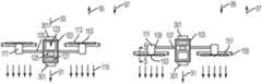
- FIG. 1is a top view of a quadrotor UAV embodying the present invention.
- FIG. 2is a front cross-sectional view of the quadrotor UAV of FIG. 1 , taken at line 2 - 2 of FIG. 1 , flying in an upright orientation.
- FIG. 3is a front cross-sectional view of the quadrotor UAV of FIG. 1 , taken at line 2 - 2 of FIG. 1 , flying in an inverted orientation.
- FIG. 4is a schematic diagram of portions of the quadrotor UAV of FIG. 1 and a ground station for the quadrotor UAV of FIG. 1 .
- FIG. 5is a cross-sectional view of a blade of the quadrotor UAV of FIG. 1 , taken at line 5 - 5 of FIG. 3 .
- FIG. 6is a partial perspective view of an alternative version of a rotor for the quadrotor UAV of FIG. 1 .
- FIG. 7is a perspective view of a thruster including a motor, a blade inversion mechanism and a rotor for one embodiment of the quadrotor UAV.
- FIG. 8is a first schematic view of the thruster of FIG. 7 .
- FIG. 9is a second schematic view of the thruster of FIG. 7 .
- FIG. 10is a perspective view of variation of the thruster of FIG. 7 .
- FIG. 11is a perspective view of another embodiment of a thruster including a motor, a blade inversion mechanism and a rotor.
- FIG. 12is a process diagram for a method embodying the present invention.
- embodiments of a UAV under the present inventionreside in a hover-capable UAV having one or more (and typically a plurality of) vertically oriented rotors (i.e., a rotorcraft).
- the UAVis configured to reverse the thrust direction of one or more of the rotors to adapt it to the orientation of the UAV with respect to gravity.
- Preferred embodiments of the inventionare quadrotor UAVs that include orientation sensors, and a control system configured to seamlessly (i.e., without requiring any user input or adaptation) change the thrust direction of each rotor to adapt to the UAVs orientation, and to adapt all command data and received sensor data accordingly.
- the present inventionprovides for a UAV that, among other tasks, can provide for comparatively safe and civilian-friendly clearing of a building by friendly personnel (e.g., military personnel or police).
- friendly personnele.g., military personnel or police.
- a military action of clearing a buildingat some point a first squad of soldiers must enter a first room the building. This activity may involve significant personal risk to the soldiers.
- One way to lower this riskis to detonate a hand grenade in the room prior to entry. Unfortunately, that hand grenade can harm innocent civilians and/or cause significant damage to an innocent civilian's property.
- a small, remotely controlled UAVis delivered (e.g., tossed) into the room prior to the soldiers' entry into the room.
- a pilottypically being another of the soldiers
- the UAVmay be flown from room to room to further check for dangers prior to the soldiers' entry.
- the UAVcan also either land on something, or affix itself to a surface such that it hangs from the surface without using rotor activity to maintain its position, such that it can serve as a security camera with a view (position and orientation) providing the soldiers' with ongoing intelligence of developing situations, and thus better security.
- a UAV 101 under a first embodiment of the inventionis a quadrotor that defines an upright orientation (see, e.g., FIG. 2 ) with respect to gravity 91 , i.e., it defines a vertical dimension 93 and an upward direction 95 with respect to the fuselage that is opposite the direction of gravity when the fuselage is in the upright orientation.
- the quadrotoralso defines an inverted orientation (see, e.g., FIG. 3 ) with respect to gravity 91 in which the upward direction 95 with respect to the fuselage is in the same direction as gravity.
- the UAV 101includes a body serving as a central fuselage 103 , and four propulsion arms 105 extending laterally from a proximal end 107 that is connected to the fuselage, to a distal end 109 .
- the UAValso includes four electric motors 111 . Each motor is attached to the distal end of a respective propulsion arm.
- Each motorhas a rotor 113 that is configured to be driven in rotation by the motor in an orientation (i.e., a rotational direction) that causes vertically downward thrust 115 with respect to gravity when the UAV is in the upright orientation with respect to gravity (see, e.g., FIG. 2 ).
- the combination of the motor and the rotorform a thruster configured to provide thrust in a primary direction of thrust with respect to the fuselage, i.e., along the vertical dimension.
- the fuselage 103includes a power source such as a battery 121 , a flight control system 123 , and a sensor system 125 that includes a camera 127 and an orientation sensor 129 .
- the control systemis configured to control the speed with which the motors drive the rotors in rotation. It is further configured to reverse the direction of rotation of the rotors, and thus the motors are configured to drive the rotors in either of two directions of rotation.
- the control systemis configured, i.e., programmed, to coordinate the operation of the rotors to accomplish controlled flight in response to a flight controller, as is known for quadrotor aircraft. This may be done in response to manual instructions sent by a flight controller in the form of a remote operator (such as is known for remote control vehicles operated by people) who is operating a ground station 131 configured with a processor 132 , a display 133 to display a video feed from the UAV camera 127 , manual controls 135 , a wireless transceiver 137 , and a power source such as a battery 139 .
- a flight controllerin the form of a remote operator (such as is known for remote control vehicles operated by people) who is operating a ground station 131 configured with a processor 132 , a display 133 to display a video feed from the UAV camera 127 , manual controls 135 , a wireless transceiver 137 , and a power source such as a battery 139 .
- the manual controls 135are human operated controls for manual flight, which may be in the form of an electronic or electromechanical device such as a game controller or standard remote control transmitter.
- the ground station wireless transceiver 137is configured to communicate via a wireless connection 141 with a UAV wireless transceiver 143 to send the operator's high-level flight control inputs to the UAV flight control system 123 , and to receive information (such as a video feed) back from the UAV camera 127 .
- high-level flight control inputsmay be generated in response to automated instructions within the flight control system in the form of a preset and/or adaptive control program.
- This control programmay use input from other sensors 145 such as a signal from a GPS (Global Positioning System) sensor.
- GPSGlobal Positioning System
- these instructionswill be directed to high-level flight instructions (e.g., fly higher, fly forward, turn, and the like) and payload instructions (e.g., turn on the camera, pan the camera, and the like).
- the control system 123is adapted to convert the high-level instructions into low-level instructions, such as instructions that activate individual motors to actuate their rotors at the desired rotor rotation rates and in the desired directions, or instructions that control the power delivered to the motors to accomplish that same purpose.
- the control system 123is further configured to control the one or more motors 111 such that it can change the primary direction of thrust with respect to the fuselage (developed by the rotors) between the upward direction 95 and the downward direction 97 .
- the primary direction of thrustis changed based on the orientation of the rotorcraft fuselage with respect to gravity. Such a change is normally done prior to takeoff. This may be done manually, i.e., at the direction of a remote operator observing the camera and manipulating the manual controls 135 , or by the control system 123 based on a signal from the orientation sensor 129 .
- the UAVcan adapt its primary direction of thrust based on its orientation.
- the primary direction of thrustmight also be changed during flight for a rapid, powered descent, should one be needed.
- the control system 123is further configured to adapt its coordination of the rotor speeds and directions based on the primary direction of thrust (which is based on the orientation of gravity).
- the low-level instructionsvary based on the orientation of the aircraft such that high-level instructions such as fly up and forward can be made without consideration of the orientation of the UAV 101 with respect to gravity.
- the UAV camera 127has a field of view, which may be static with respect to the fuselage, or movable via an actuator.
- the camerais a directional sensor configured to sense the external environment, and provides a video feed for display on the display 133 , allowing an operator to control the UAV, and providing useful information to the operator (such as the presence of dangers to personnel in the vicinity of the UAV).
- the control system 123is configured to adjust the signal of this directional sensor (and any other onboard directional sensors) based on the primary direction of thrust.
- a remote operator or a person reviewing the sensor datawill view the information (e.g., the video feed) in a correct orientation with respect to gravity without having to take any manual procedures to correct the orientation.
- the control systemautomatically flips the picture so it is right side up when viewed by the operator.
- the UAV 101could deliver an uncorrected sensor stream (.e.g., a video feed not corrected for the orientation with respect to gravity), along with an orientation signal (from the orientation sensor 129 ) indicating the orientation of the UAV with respect to gravity.
- the orientation signalmay be continuously sent, or may be sent at the initiation of each flight.
- the ground station 131would then be configured to correct the orientation of the information displayed on the display 133 based on the orientation signal (which is in turn based on the orientation of the UAV with respect to gravity).
- each rotor 113 of the UAVhas a plurality of blades 151 that extend longitudinally out from a hub 153 along a longitudinal blade axis 157 , and blade guard 155 surrounding the path through which the blades rotate.
- the longitudinal axisis normal to the cross-sectional view of FIG. 5 .
- the blade guardprotects people and things near the UAV from being hit by a blade. At the same time, the blade guard guards against things becoming entangled in the rotor, and against the rotor being inadvertently stopped when the UAV strikes something.
- the rotor blades 151are not configured as airfoils in which the camber is different (e.g., larger) near a leading edge than near a trailing edge (as is typical for propellers and rotors). Instead, the blade is characterized by a 2-fold symmetry along the longitudinal blade axis (i.e., the cross section of the blade looks no different when rotated 180° around the longitudinal blade axis. As a result, each blade is configured to produce equal thrust in either direction of rotation for a given rotational speed.
- each blade cambercould be configured to be adaptable based on the direction of rotation of the rotor.
- each bladeincludes a section of sailcloth 201 that extends between two relatively rigid frame elements 203 that extend out from a rotor hub 205 .
- the frame elementsare offset from one another such that with the sailcloth hung loosely, the sailcloth will bow out during rotation of the rotor.
- the sailclothwill bow out in a shape adapted to produce thrust in a first thrust direction 213 .
- the sailclothwill bow out in another shape that is adapted to produce thrust in the opposite thrust direction.
- blades 501are configured with an efficient camber and shape for producing thrust in one direction, as is well known for aircraft propellers and helicopter rotors.
- the rotoris configured with a blade inversion mechanism 503 that rotates each blade around its own longitudinal blade axis 505 such that the blade can be oriented in two positions that are substantially 180 degrees apart.
- the bladeis thereby adjustable to be oriented in the correct direction to create efficient thrust in either direction (i.e., up or down with respect to the rotorcraft, in other words, down with respect to gravity).
- the bladesare adjustably oriented based upon the direction the rotor is rotating, which in turn is based on the orientation of the rotorcraft with respect to gravity.
- the two blades 501are mounted on a blade shaft 507 that extends along the blade axes 505 of both blades.
- Rigidly mounted on the blade shaftis a circular gear 509 (in the form of a spur gear) forming a gear plane that is normal to the blade shaft and the blade axes.
- the motoris within a motor housing 511 , and is configured to rotate a motor shaft 513 with respect to the motor housing around a motor axis of rotation 515 .
- the blade inversion mechanism 503includes an inversion disk 521 , a support 523 , a first stop 525 and a second stop 527 . The support, the first stop and the second stop are each attached to the inversion disk.
- the inversion diskis a flat, circular disk that is rotationally symmetric around the motor axis of rotation 515 and forms a drive surface 529 .
- the inversion disk 521is rigidly attached to the motor shaft 513 with the drive surface normal to the motor axis of rotation.
- Imprinted into the drive surface 529 of the inversion disk 521is a circular track of teeth 531 concentrically encircling the support 523 , effectively forming the inversion disk into an inversion gear 533 in the form of a crown gear.
- the support 523is restrained by the inversion disk 521 such that it is held in place with respect to the inversion disk, but can freely rotate around the motor axis of rotation 515 with respect to the inversion disk.
- the blade shaft 507is restrained by the support 523 such that the blade shaft is held in place with respect to the support, but can freely rotate around the blade axes 505 with respect to the support.
- the circular gear 509has a plurality of teeth 535 .
- the circular gear teeth 535are in contact with the inversion gear teeth 531 such that the circular gear 509 is meshed with the inversion gear 533 .
- the blades 501 , blade shaft 507 and support 523can freely rotate around the motor axis of rotation 515 with respect to the inversion disk 521 .
- the inversion gear 533which is meshed with the circular gear 509 , drives the blades and the blade shaft in rotation around the blade axes 505 with respect to the support 523 .
- the first and second stops 525 , 527are rigidly affixed to the inversion disk 521 on opposite sides of the support 523 . They extend up into the path of the blade shaft 507 as it rotates around the motor axis of rotation 515 with respect to the inversion disk, providing first and second limits to the range of positions through which the blade shaft can rotate with respect to the inversion disk. While this function could be accomplished by a single stop, it is preferable to use two in order to keep the rotor rotationally balanced around the motor axis of rotation 515 . Alternatively, other balancing mechanisms may be used to rotationally balance the rotor.
- the bladesare oriented for efficient thrust in a first direction 541 parallel to the motor axis of rotation 515 .
- the bladesare oriented for efficient thrust in a second direction 543 parallel to the motor axis of rotation 515 .
- the first and second directionsare opposite one another.
- the orientation of the blades 501 around the blade axes 505 while in the first positionis substantially 180 degrees from the orientation of the blades around the blade axes while in the second position, with respect to the support.
- the first and second stops 525 , 527are magnetic, and the blade shaft 507 is composed of a ferromagnetic material. As a result, when the blade shaft is in the first position the magnets will apply a force attempting to hold it in the first position. Likewise, when the blade shaft is in the second position the magnets will apply a force attempting to hold it in the second position.
- the motorWhen initially activated, the motor will apply a rotational force around the motor axis of rotation 515 to the inversion disk 521 , causing it to spin. Because the blades 501 and blade shaft 507 can rotate around the motor axis of rotation, with respect to the inversion disk, the rotational inertia of the blades and blade shaft around the motor axis of rotation 515 will cause the inversion disk to rotate with respect to the blades and blade shaft.
- the force of the motoris greater than the restraining force of the magnets, so the blade shaft will pull away from the magnetic stops if the blade shaft is in the wrong limit position around the motor axis of rotation.
- the meshed gears 509 , 531will in turn drive the blades and blade shaft in rotation around the blade axes 505 until the blade shaft reaches the appropriate limit position (either the first or second limit of the range of positions through which the blade shaft can rotate around the motor axis of rotation) with respect to the inversion disk.
- the magnetic nature of the stops with the blade shaft at the newly reached limit positionwill limit the blade shafts from bouncing off of the stops as the blade shaft reaches the new position.
- the first and second stopswill drive the blades and blade shaft in rotation around the motor axis.
- the blades and blade shafthave a much lower rotational inertia around the blade axis than around the motor axis of rotation, thus leading to the gears causing rotation around the blade axes rather than rotation around the motor axis of rotation.
- the bladesmay first be driven in the wrong direction, and then be driven in the appropriate position. The angular momentum of the blades spinning in the wrong direction will then help to break the magnetic hold of the stops on the blade shaft.
- FIGS. 8 and 9depict the transition of the thruster between then upright orientation (shown in FIG. 8 ) and the inverted orientation (shown in FIG. 9 ).
- a first relative orientation 601the inversion disk 521 is rotating in a first direction 603 around the motor axis of rotation (relative to the motor housing), which causes the rotor (including the blades 501 and blade shaft 507 ) to rotate in a second direction 605 around the motor axis of rotation, relative to the inversion disk.
- the bladesare positioned for upright flight, and the inversion disk drives the blades in rotation around the motor axis of rotation (relative to the motor housing) to provide upright vertical thrust.
- the inversion disk 521is rotating in a third direction 613 around the motor axis of rotation (relative to the motor housing), which causes the rotor to rotate in a fourth direction 615 around the motor axis of rotation, relative to the inversion disk.
- the first and third directions of rotation relative to the motor housingare opposite one another.
- the second and fourth directions of rotation relative to the inversion diskare opposite one another.
- the bladesare positioned for inverted flight, and the inversion disk drives the blades in rotation around the motor axis of rotation (relative to the motor housing) to provide inverted vertical thrust.
- the first and second positions of the blades and blade shaftare almost 180 degree apart around the motor axis of rotation. If four stops are used (or two stops with additional weights to balance the rotor), a much smaller rotation could be set between the first and second position limits. This could lead to a significantly smaller circular gear as compared to the size of the inversion disk.
- blades 701are again configured with an efficient camber and shape for producing thrust in one direction, as is well known for aircraft propellers and helicopter rotors.
- the rotoris configured with a similar blade inversion mechanism 703 that rotates each blade around its own longitudinal blade axis 705 such that the blade can be oriented in two positions that are substantially 180 degrees apart.
- the bladeis thereby adjustable to be oriented in the correct direction to create efficient thrust in either direction (i.e., up or down with respect to the rotorcraft, in other words, down with respect to gravity).
- the bladesare adjustably oriented based upon the direction the rotor is rotating, which in turn is based on the orientation of the rotorcraft with respect to gravity.
- the two blades 701are mounted on a blade shaft 707 that extends along the blade axes 705 of both blades.
- a circular gear 709(in the form of a spur gear) forming a gear plane that is normal to the blade shaft and the blade axes.
- a circular-gear stopmounted on the circular gear is a circular-gear stop having a first magnetic end 726 and a second magnetic end 728 .
- the motoris within a motor housing, and is configured to rotate a motor shaft 713 with respect to the motor housing around a motor axis of rotation 715 .
- the blade inversion mechanism 703includes an inversion disk 721 , a support 723 , a first inversion-disk stop 725 and a second inversion-disk stop 727 .
- the support, the first inversion-disk stop and the second inversion-disk stopare each attached to the inversion disk.
- the inversion diskis a flat, circular disk that is rotationally symmetric around the motor axis of rotation 715 and forms a drive surface 729 .
- the inversion disk 721is rigidly attached to the motor shaft 713 with the drive surface normal to the motor axis of rotation.
- Imprinted into the drive surface 729 of the inversion disk 721is a circular track of teeth 731 concentrically encircling the support 723 , effectively forming the inversion disk into an inversion gear 733 in the form of a crown gear.
- the support 723is restrained by the inversion disk 721 such that it is held in place with respect to the inversion disk, but can freely rotate around the motor axis of rotation 715 with respect to the inversion disk.
- the blade shaft 707is restrained by the support 723 such that the blade shaft is held in place with respect to the support, but can freely rotate around the blade axes 705 with respect to the support.
- the circular gear 709has a plurality of teeth 735 .
- the circular gear teeth 735are in contact with the inversion gear teeth 731 such that the circular gear 709 is meshed with the inversion gear 733 .
- the blades 701 , blade shaft 707 and support 723can freely rotate around the motor axis of rotation 715 with respect to the inversion disk 721 .
- the inversion gear 733which is meshed with the circular gear 709 , drives the blades and the blade shaft in rotation around the blade axes 705 with respect to the support 723 .
- the first and second inversion-disk stops 725 , 727are rigidly affixed to the inversion disk 721 on opposite sides of the support 723 . They are positioned such that they respectively block the path of the first magnetic end 726 and a second magnetic end 728 of the circular gear stop as the circular gear rotates around the motor axis of rotation 715 with respect to the inversion disk, providing first and second limits to the range of positions through which the blade shaft can rotate with respect to the inversion disk.
- the bladesare oriented for efficient thrust in a first direction 741 parallel to the motor axis of rotation 715 .
- the bladesare oriented for efficient thrust in a second direction 743 parallel to the motor axis of rotation 715 .
- the first and second directionsare opposite one another.
- the orientation of the blades 701 around the blade axes 705 while in the first positionis substantially 180 degrees from the orientation of the blades around the blade axes while in the second position, with respect to the support.
- the first and second inversion gear stops 725 , 727are magnetic, and the two ends of the circular gear stop are magnetic. As a result, when the blade shaft is in the first position, two of the magnets will apply a force attempting to hold it in the first position. Likewise, when the blade shaft is in the second position, the other two magnets will apply a force attempting to hold it in the second position.
- the motorWhen initially activated, the motor will apply a rotational force around the motor axis of rotation 715 to the inversion disk 721 , causing it to spin. Because the blades 701 and blade shaft 707 can rotate around the motor axis of rotation, with respect to the inversion disk, the rotational inertia of the blades and blade shaft around the motor axis of rotation 715 will cause the inversion disk to rotate with respect to the blades and blade shaft.
- the force of the motoris greater than the restraining force of the magnets, so the blade shaft will pull away from the magnetic stops if the blade shaft is in the wrong limit position around the motor axis of rotation.
- the meshed gears 709 , 731will in turn drive the blades and blade shaft in rotation around the blade axes 705 until the blade shaft reaches the appropriate limit position (either the first or second limit of the range of positions through which the blade shaft can rotate around the motor axis of rotation) with respect to the inversion disk.
- the magnetic nature of the stops with the blade shaft at the newly reached limit positionwill limit the blade shafts from bouncing off of the stops as the blade shaft reaches the new position.
- the stopswill drive the blades and blade shaft in rotation around the motor axis.
- the blades and blade shafthave a much lower rotational inertia around the blade axis than around the motor axis of rotation, thus leading to the gears causing rotation around the blade axes rather than rotation around the motor axis of rotation.
- the bladesmay first be driven in the wrong direction, and then be driven in the appropriate position. The angular momentum of the blades spinning in the wrong direction will then help to break the magnetic hold of the stops on the blade shaft.
- the rotorcould be configured with more than two blades. To do that, separate gearing would likely be provided for each blade, or for each pair of blades. In yet other variations, this blade inversion mechanism could be driven through a variety of other structural arrangements, both using other arrangements of gears and/or other rotational mechanisms.
- the blade inversioncould be driven by a separate motor mechanism that is actively controlled by a control system.
- a motor shaft 813is configured to be driven in rotation around a motor axis of rotation 815 by a motor.
- a support 823is concentrically received on the motor shaft, and is configured to freely rotate around the motor axis of rotation with respect to the motor shaft.
- the supporthas a support shaft 841 extending laterally in a direction forming a blade axis 805 for a blade 801 .
- the bladeis carried on a blade shaft 807 , which is concentrically received on the support shaft, and is configured to freely rotate around the blade axis with respect to the support 823 .
- the blade shaft 807has first and second arms 843 extending in opposite directions normal to the blade axis 805 .
- Each armis provided with a cable 845 that is wrapped around and attached to the motor shaft 813 .
- the cables of the two armsare wrapped in opposite directions.
- a first arm's cablewraps tightly around the motor shaft, while the second arm's cable loosens up.
- the tightly wrapped first-arm cablepulls on its arm, causing the first arm to drive the blade to rotate around the blade axis of rotation with respect to the support 823 , and then causing the blade to rotate around the motor axis of rotation.
- the various blade inversion mechanismsare not limited to mechanisms that rotate each blade 180 degrees around its blade axis. If differing amounts of thrust are required in the opposite directions, or if differing environmental conditions exist between the use in one direction and in the other direction, then it might be preferable to rotate to positions a little over or a little under 180 degrees. Moreover, while the two limit positions are generally 180 degrees apart, the blades could be rotated much more to travel between those positions. For example, if a much smaller circular gear is desired with respect to the inversion disk, the gearing could be configured for the blades to rotate 540 degrees (i.e., 180 degrees plus 360 degrees), or 900 degrees (i.e., 180 degrees plus 720 degrees).
- the blade inversion mechanismmay have significant uses outside of the aircraft arts.
- a rotor having this blade inversion mechanismcould be used for a wide variety of fans ranging from ceiling fans to fans used in a wide variety of industrial applications.
- the blade inversion mechanismmay also have marine applications.
- the embodimentmay further include one or more surface-connection devices 301 configured to allow the rotorcraft to affix itself to a surface such that it hangs from the surface, and thus that it does not need rotor activity to maintain the position.
- Such surface-connection devicesmay be of a variety of types (e.g., magnets, adhesive devices, hook and latch materials, and suction devices), and their selection will depend on the nature of the environment in which the UAV will operate.
- the reversibility of the motorscan provide for an increased ability of the rotorcraft to break free of such a connection once it is no longer desired. For example, two rotors pushing one way and two pushing the other might provide enough torque to free a hook and latch attachment.
- embodimentsinclude variations of the above-described information.
- such embodimentsmay be based on other numbers of motors and/or rotors, and more generally can be described as having one or more motors, and/or one or more rotors.
- a method of gathering intelligence (such as of dangers) prior to entering a room under the inventionresides in the steps of 1) delivering 401 (e.g., tossing) a UAV such as the above-described UAV quadrotor into the room, 2) adapting 403 the UAV to have a primary direction of thrust based on the orientation of the UAV with respect to gravity once it has come to rest in the room, 3) instructing 405 the UAV to fly, and 4) scanning 407 the room using a sensor such as the camera to gather intelligence, such as determining the presence of dangers. While these steps will typically be conducted in sequential order (and/or simultaneously for some of the steps), other orders are possible, such as scanning the room prior to flight.
- the methodmay also include the step of 5) if the flight of the UAV is interrupted prior to the completion of steps (2) through (4) (or before the completion of all the steps if there are more steps), then restarting 411 all the steps from step (2).
- the methodmay alternatively or further include the steps of 5) instructing 421 the UAV to fly to one or more additional rooms, and 6) scanning 423 the one or more additional rooms, using the sensor, to further gather intelligence, such as determining the presence of additional dangers, prior to entry.
- the methodmay also or alternatively include the steps of 5) affixing 431 the UAV to hang from a surface in a position and orientation in which the sensor can provide continuing intelligence, such as of dangers, and 6) continuing 433 to scan using the sensor to gather intelligence, such as of developing dangers, from the position in which the UAV is affixed.
- the inventioncomprises apparatus and methods for designing and for producing UAVs, as well as the apparatus and methods of using the UAV. Additionally, the various embodiments of the invention can incorporate various combinations of these features with existing UAV missions. In short, the above disclosed features can be combined in a wide variety of configurations within the anticipated scope of the invention.
Landscapes
- Engineering & Computer Science (AREA)
- Aviation & Aerospace Engineering (AREA)
- Mechanical Engineering (AREA)
- Physics & Mathematics (AREA)
- Radar, Positioning & Navigation (AREA)
- Remote Sensing (AREA)
- General Physics & Mathematics (AREA)
- Automation & Control Theory (AREA)
- Acoustics & Sound (AREA)
- Human Computer Interaction (AREA)
- Toys (AREA)
Abstract
Description
Claims (20)
Priority Applications (1)
| Application Number | Priority Date | Filing Date | Title |
|---|---|---|---|
| US16/449,457US10870495B2 (en) | 2011-03-22 | 2019-06-24 | Invertible aircraft |
Applications Claiming Priority (6)
| Application Number | Priority Date | Filing Date | Title |
|---|---|---|---|
| US201161465705P | 2011-03-22 | 2011-03-22 | |
| PCT/US2012/000160WO2013105926A1 (en) | 2011-03-22 | 2012-03-23 | Invertible aircraft |
| US14/034,448US9199733B2 (en) | 2011-03-22 | 2013-09-23 | Invertible aircraft |
| US14/885,972US9650135B2 (en) | 2011-03-22 | 2015-10-16 | Invertible aircraft |
| US15/594,342US10329025B2 (en) | 2011-03-22 | 2017-05-12 | Invertible aircraft |
| US16/449,457US10870495B2 (en) | 2011-03-22 | 2019-06-24 | Invertible aircraft |
Related Parent Applications (1)
| Application Number | Title | Priority Date | Filing Date |
|---|---|---|---|
| US15/594,342ContinuationUS10329025B2 (en) | 2011-03-22 | 2017-05-12 | Invertible aircraft |
Publications (2)
| Publication Number | Publication Date |
|---|---|
| US20200047906A1 US20200047906A1 (en) | 2020-02-13 |
| US10870495B2true US10870495B2 (en) | 2020-12-22 |
Family
ID=48781750
Family Applications (5)
| Application Number | Title | Priority Date | Filing Date |
|---|---|---|---|
| US14/034,448ActiveUS9199733B2 (en) | 2011-03-22 | 2013-09-23 | Invertible aircraft |
| US14/885,972Active - ReinstatedUS9650135B2 (en) | 2011-03-22 | 2015-10-16 | Invertible aircraft |
| US14/954,983Active - ReinstatedUS9511859B2 (en) | 2011-03-22 | 2015-11-30 | Invertible aircraft |
| US15/594,342ActiveUS10329025B2 (en) | 2011-03-22 | 2017-05-12 | Invertible aircraft |
| US16/449,457Active - ReinstatedUS10870495B2 (en) | 2011-03-22 | 2019-06-24 | Invertible aircraft |
Family Applications Before (4)
| Application Number | Title | Priority Date | Filing Date |
|---|---|---|---|
| US14/034,448ActiveUS9199733B2 (en) | 2011-03-22 | 2013-09-23 | Invertible aircraft |
| US14/885,972Active - ReinstatedUS9650135B2 (en) | 2011-03-22 | 2015-10-16 | Invertible aircraft |
| US14/954,983Active - ReinstatedUS9511859B2 (en) | 2011-03-22 | 2015-11-30 | Invertible aircraft |
| US15/594,342ActiveUS10329025B2 (en) | 2011-03-22 | 2017-05-12 | Invertible aircraft |
Country Status (2)
| Country | Link |
|---|---|
| US (5) | US9199733B2 (en) |
| WO (1) | WO2013105926A1 (en) |
Cited By (1)
| Publication number | Priority date | Publication date | Assignee | Title |
|---|---|---|---|---|
| US20250019096A1 (en)* | 2022-03-22 | 2025-01-16 | Aerix Systems | Omnidirectional propelled vehicle with minimal overall dimensions |
Families Citing this family (119)
| Publication number | Priority date | Publication date | Assignee | Title |
|---|---|---|---|---|
| WO2013105926A1 (en)* | 2011-03-22 | 2013-07-18 | Aerovironment Inc. | Invertible aircraft |
| US9384668B2 (en) | 2012-05-09 | 2016-07-05 | Singularity University | Transportation using network of unmanned aerial vehicles |
| US9549742B2 (en) | 2012-05-18 | 2017-01-24 | OrthAlign, Inc. | Devices and methods for knee arthroplasty |
| US8844860B2 (en)* | 2012-07-06 | 2014-09-30 | Lapcad Engineering, Inc. | Foldable rise and stare vehicle |
| IL222053A (en)* | 2012-09-23 | 2016-11-30 | Israel Aerospace Ind Ltd | System, method and computer program product for maneuvering an air vehicle |
| US20140263822A1 (en)* | 2013-03-18 | 2014-09-18 | Chester Charles Malveaux | Vertical take off and landing autonomous/semiautonomous/remote controlled aerial agricultural sensor platform |
| US10569868B2 (en)* | 2013-04-02 | 2020-02-25 | Hood Technology Corporation | Multicopter-assisted system and method for launching and retrieving a fixed-wing aircraft |
| US10583920B2 (en) | 2013-04-02 | 2020-03-10 | Hood Technology Corporation | Multicopter-assisted system and method for launching and retrieving a fixed-wing aircraft |
| CA2997790C (en)* | 2013-05-15 | 2021-06-29 | Autel Robotics Usa Llc | Compact unmanned rotary aircraft |
| US20160137293A1 (en)* | 2013-10-15 | 2016-05-19 | Skypersonic | Enclosed drone apparatus and method for use thereof |
| EP3057812B1 (en)* | 2013-10-15 | 2018-12-05 | Skypersonic LLC | Enclosed drone apparatus and method for use thereof |
| EP3074832A4 (en) | 2013-11-27 | 2017-08-30 | The Trustees Of The University Of Pennsylvania | Multi-sensor fusion for robust autonomous flight in indoor and outdoor environments with a rotorcraft micro-aerial vehicle (mav) |
| US9489937B1 (en)* | 2014-03-07 | 2016-11-08 | Trace Live Network Inc. | Real-time noise reduction system for dynamic motor frequencies aboard an unmanned aerial vehicle (UAV) |
| WO2015149000A1 (en)* | 2014-03-27 | 2015-10-01 | The Board Of Regents For Oklahoma State University | Spherical vtol aerial vehicle |
| US9272784B2 (en)* | 2014-05-19 | 2016-03-01 | Brian Dale Nelson | Vertical takeoff winged multicopter |
| JP6293304B2 (en)* | 2014-05-21 | 2018-03-14 | エスゼット ディージェイアイ テクノロジー カンパニー リミテッドSz Dji Technology Co.,Ltd | Remote control device, control system, and control method |
| CN104102133B (en)* | 2014-07-17 | 2016-08-17 | 杭州职业技术学院 | A kind of four rotor pid parameter optimization methods based on the artificial bee colony algorithm improved |
| US9296477B1 (en) | 2014-07-21 | 2016-03-29 | Glenn Coburn | Multi-rotor helicopter |
| US20160023751A1 (en)* | 2014-07-28 | 2016-01-28 | The Board of Regents of the Nevada System of High- er Education on Behalf of the University of Nevad | Energy harvesting mechanism for gyroplanes and gyrocopters |
| US10850827B2 (en)* | 2014-08-21 | 2020-12-01 | Juan Gerardo Narvaez Tijerina | Airfoils for stunt flights |
| FR3025114A1 (en) | 2014-08-26 | 2016-03-04 | Parrot | DYNAMIC START CONTROL METHOD LAUNCHING ROTARY SAIL DRONE |
| JP6167425B2 (en) | 2014-08-29 | 2017-07-26 | エスゼット ディージェイアイ テクノロジー カンパニー リミテッドSz Dji Technology Co.,Ltd | Unmanned aerial vehicle and voice data collection method using unmanned aerial vehicle |
| US9754496B2 (en) | 2014-09-30 | 2017-09-05 | Elwha Llc | System and method for management of airspace for unmanned aircraft |
| US20160272310A1 (en)* | 2014-12-04 | 2016-09-22 | Elwha Llc | Reconfigurable unmanned aircraft system |
| US9919797B2 (en) | 2014-12-04 | 2018-03-20 | Elwha Llc | System and method for operation and management of reconfigurable unmanned aircraft |
| FR3030451A1 (en)* | 2014-12-22 | 2016-06-24 | Parrot | ACCESSORY TO MAKE AN AMPHIBIOUS DRONE |
| US10126745B2 (en)* | 2015-01-04 | 2018-11-13 | Hangzhou Zero Zero Technology Co., Ltd. | System and method for automated aerial system operation |
| US10719080B2 (en) | 2015-01-04 | 2020-07-21 | Hangzhou Zero Zero Technology Co., Ltd. | Aerial system and detachable housing |
| US9836053B2 (en) | 2015-01-04 | 2017-12-05 | Zero Zero Robotics Inc. | System and method for automated aerial system operation |
| US9677564B1 (en) | 2015-01-15 | 2017-06-13 | X Development Llc | Magnetic propeller safety device |
| WO2016123201A1 (en) | 2015-01-27 | 2016-08-04 | The Trustees Of The University Of Pennsylvania | Systems, devices, and methods for robotic remote sensing for precision agriculture |
| FR3032687B1 (en)* | 2015-02-16 | 2018-10-12 | Hutchinson | AERODYNE VTOL WITH SOUFFLANTE (S) AXIALE (S) CARRIER (S) |
| NL2014310B1 (en)* | 2015-02-18 | 2016-10-13 | Monkeywings Ip B V | Inverted Drone. |
| US9501061B2 (en) | 2015-02-24 | 2016-11-22 | Qualcomm Incorporated | Near-flight testing maneuvers for autonomous aircraft |
| US9469394B2 (en)* | 2015-03-10 | 2016-10-18 | Qualcomm Incorporated | Adjustable weight distribution for drone |
| US10831186B2 (en)* | 2015-04-14 | 2020-11-10 | Vantage Robotics, Llc | System for authoring, executing, and distributing unmanned aerial vehicle flight-behavior profiles |
| CN107614376B (en) | 2015-05-19 | 2021-05-28 | 株式会社阿荣奈斯特 | Gyrocopter |
| US20170329351A1 (en)* | 2015-05-22 | 2017-11-16 | Qualcomm Incorporated | Apparatus-assisted sensor data collection |
| JP6435991B2 (en)* | 2015-05-28 | 2018-12-12 | 株式会社村田製作所 | Electric aircraft |
| US9764829B1 (en)* | 2015-06-09 | 2017-09-19 | Amazon Technologies, Inc. | Multirotor aircraft with enhanced yaw control |
| US10386188B2 (en)* | 2015-06-29 | 2019-08-20 | Yuneec Technology Co., Limited | Geo-location or navigation camera, and aircraft and navigation method therefor |
| US9878787B2 (en) | 2015-07-15 | 2018-01-30 | Elwha Llc | System and method for operating unmanned aircraft |
| US10037028B2 (en)* | 2015-07-24 | 2018-07-31 | The Trustees Of The University Of Pennsylvania | Systems, devices, and methods for on-board sensing and control of micro aerial vehicles |
| CN106706843B (en)* | 2015-08-24 | 2019-09-10 | 洛阳瑞昌环境工程有限公司 | A kind of torch burning pollutant emission detection system and detection method |
| US10884430B2 (en) | 2015-09-11 | 2021-01-05 | The Trustees Of The University Of Pennsylvania | Systems and methods for generating safe trajectories for multi-vehicle teams |
| KR101607816B1 (en)* | 2015-10-26 | 2016-03-31 | 이진우 | Drone with air guide part |
| EP3374263A4 (en)* | 2015-11-10 | 2019-05-08 | Matternet, Inc. | METHODS AND TRANSPORT SYSTEMS USING PILOT-FREE AIR VEHICLES |
| USD805425S1 (en)* | 2015-11-27 | 2017-12-19 | Eric Hanscom | Drone-shaped tie tack |
| CN108698690B (en) | 2015-12-07 | 2021-08-17 | 特克斯特罗恩系统公司 | UAV with sail assembly providing efficient vertical takeoff and landing capability |
| US9878784B2 (en)* | 2015-12-11 | 2018-01-30 | Amazon Technologies, Inc. | Propeller alignment devices |
| WO2017111971A1 (en)* | 2015-12-22 | 2017-06-29 | Intel Corporation | UNIVERSAL CONTROLLER FOR ROBUST TRAJECTORY TRACKING IN MULTIROTOR UNMANNED AERIAL VEHICLES (UAVs) |
| US10183744B2 (en) | 2016-02-10 | 2019-01-22 | Lockheed Martin Corporation | Magnetic orientation detent |
| US9828096B2 (en)* | 2016-02-23 | 2017-11-28 | The Boeing Company | Movable control surface ejection system |
| JP6006452B1 (en)* | 2016-04-07 | 2016-10-12 | ヒロボー株式会社 | Helicopter rotor head, multi-rotor helicopter and helicopter |
| US10435144B2 (en) | 2016-04-24 | 2019-10-08 | Hangzhou Zero Zero Technology Co., Ltd. | Aerial system propulsion assembly and method of use |
| US20170313400A1 (en)* | 2016-04-27 | 2017-11-02 | Atlas Dynamic Limited | Collapsible unmanned aerial vehicle (uav) |
| EP3458359B1 (en)* | 2016-05-18 | 2021-10-20 | Kyriacos Zachary | Variable pitch propeller apparatus and variable thrust aircraft using smae |
| CN107635871B (en)* | 2016-05-29 | 2020-02-07 | 深圳市欸阿技术有限公司 | Unmanned aerial vehicle |
| CN109476372A (en)* | 2016-07-12 | 2019-03-15 | 深圳市大疆创新科技有限公司 | System and method for multi-orientation flight |
| US10569861B2 (en)* | 2016-08-01 | 2020-02-25 | Kitty Hawk Corporation | Bistable pitch propeller system with unidirectional propeller rotation |
| US10843790B2 (en) | 2016-08-01 | 2020-11-24 | Kitty Hawk Corporation | Bistable pitch propeller system with bidirectional propeller rotation |
| CN106716284B (en)* | 2016-08-31 | 2019-09-24 | 深圳市大疆创新科技有限公司 | Control method, device and system, aircraft, carrier and manipulation device |
| CN106314779B (en)* | 2016-09-19 | 2020-02-18 | 深圳一电航空技术有限公司 | UAV and UAV control method |
| CN109789926B (en)* | 2016-10-03 | 2022-10-21 | 盐城辉空科技有限公司 | delivery rotorcraft |
| US10479496B2 (en) | 2016-10-31 | 2019-11-19 | Lockheed Martin Corporation | Magnetic orientation detent with motor assist |
| US20180186472A1 (en)* | 2016-12-30 | 2018-07-05 | Airmada Technology Inc. | Method and apparatus for an unmanned aerial vehicle with a 360-degree camera system |
| JP6919222B2 (en) | 2017-02-27 | 2021-08-18 | セイコーエプソン株式会社 | Display device and control method of display device |
| GB2557715B (en) | 2017-02-28 | 2019-04-17 | Matthew Russell Iain | Unmanned aerial vehicles |
| CA3056495A1 (en) | 2017-03-14 | 2018-09-20 | OrthAlign, Inc. | Soft tissue measurement & balancing systems and methods |
| US10618646B2 (en) | 2017-05-26 | 2020-04-14 | Textron Innovations Inc. | Rotor assembly having a ball joint for thrust vectoring capabilities |
| US10351232B2 (en) | 2017-05-26 | 2019-07-16 | Bell Helicopter Textron Inc. | Rotor assembly having collective pitch control |
| USD902078S1 (en) | 2017-06-07 | 2020-11-17 | MerchSource, LLC | Drone |
| USD851540S1 (en) | 2017-06-07 | 2019-06-18 | MerchSource, LLC | Drone |
| US10730622B2 (en) | 2017-06-14 | 2020-08-04 | Bell Helicopter Textron Inc. | Personal air vehicle with ducted fans |
| USD825380S1 (en) | 2017-06-27 | 2018-08-14 | MerchSource, LLC | Drone for kids |
| US10095242B1 (en)* | 2017-07-05 | 2018-10-09 | Qualcomm Incorporated | Invertible drone for selective power capture |
| USD825669S1 (en) | 2017-07-10 | 2018-08-14 | MerchSource, LLC | Drone car |
| CN109229361A (en)* | 2017-07-11 | 2019-01-18 | 深圳市道通智能航空技术有限公司 | Electric machine control system and unmanned plane |
| US10745102B2 (en)* | 2017-07-17 | 2020-08-18 | Griff Aviation As | Swingable arm mount for an aerial vehicle having a lift generating means, and an aerial vehicle, advantageously a multicopter with a swingable arm mount |
| USD852091S1 (en) | 2017-07-20 | 2019-06-25 | MerchSource, LLC | Drone |
| CN109407684B (en)* | 2017-08-18 | 2022-08-19 | 昊翔电能运动科技(昆山)有限公司 | Rotor unmanned aerial vehicle attitude control method and system |
| USD862285S1 (en)* | 2017-08-25 | 2019-10-08 | MerchSource, LLC | Drone |
| US10852749B2 (en)* | 2017-08-28 | 2020-12-01 | Nec Corporation | Learning good features for visual odometry |
| USD846445S1 (en) | 2017-09-15 | 2019-04-23 | MerchSource, LLC | Drone |
| USD864082S1 (en)* | 2017-10-09 | 2019-10-22 | Guangdong Shiji Technology Co., Ltd | Quadcopter |
| USD864083S1 (en)* | 2017-10-09 | 2019-10-22 | Guangdong Shiji Technology Co., Ltd | Quadcopter |
| USD858353S1 (en)* | 2017-10-30 | 2019-09-03 | Shenzhen Valuelink E-Commerce Co., Ltd. | Drone |
| USD858352S1 (en)* | 2017-10-30 | 2019-09-03 | Shenzhen Valuelink E-Commerce Co., Ltd. | Drone |
| CN107826244B (en)* | 2017-11-15 | 2021-03-09 | 安徽工程大学 | Six rotary device of aircraft |
| US11267555B2 (en)* | 2018-01-08 | 2022-03-08 | GEOSAT Aerospace & Technology | Methods and unmanned aerial vehicles for longer duration flights |
| FR3077267B1 (en)* | 2018-01-30 | 2020-03-06 | Guillaume Emmanuel Marie Nicolle | AERODYNE WITHOUT A PILOT |
| JP7238380B2 (en)* | 2018-02-05 | 2023-03-14 | 株式会社リコー | Flight equipment, flight systems, and structural inspection systems |
| US10909961B2 (en)* | 2018-02-21 | 2021-02-02 | Gopro, Inc. | Reduction of microphone audio noise from gimbal motor |
| USD864022S1 (en)* | 2018-03-30 | 2019-10-22 | Shenzhen Valuelink E-Commerce Co., Ltd. | Unmanned aerial vehicle |
| USD860047S1 (en)* | 2018-04-08 | 2019-09-17 | Shenzhen Valuelink E-Commerce Co., Ltd. | Unmanned aerial vehicle |
| US10336452B1 (en)* | 2018-04-16 | 2019-07-02 | Muye Jia | Drone with no external propeller blades |
| US10988241B2 (en) | 2018-04-20 | 2021-04-27 | Skypersonic, Llc | Removable cage for drone |
| USD873175S1 (en)* | 2018-05-23 | 2020-01-21 | Shenzhen Hubsan Technology Co., Ltd. | Drone |
| WO2020033140A1 (en)* | 2018-07-23 | 2020-02-13 | Airgility, Inc. | System of play platform for multi-mission application spanning any one or combination of domains or environments |
| JP6648802B2 (en)* | 2018-10-26 | 2020-02-14 | 株式会社村田製作所 | Electric aircraft |
| US11440671B2 (en)* | 2019-01-24 | 2022-09-13 | Amazon Technologies, Inc. | Adjustable motor fairings for aerial vehicles |
| EP3699083A1 (en)* | 2019-02-20 | 2020-08-26 | Flyability SA | Unmanned aerial vehicle with collision tolerant propulsion and controller |
| US11080327B2 (en)* | 2019-04-18 | 2021-08-03 | Markus Garcia | Method for the physical, in particular optical, detection of at least one usage object |
| US11235892B2 (en) | 2019-05-22 | 2022-02-01 | Hood Technology Corporation | Aircraft retrieval system and method |
| WO2020237566A1 (en)* | 2019-05-30 | 2020-12-03 | 深圳市大疆创新科技有限公司 | Unmanned aerial vehicle, control terminal thereof and attitude adjusting method therefor, and storage medium |
| US10895637B1 (en)* | 2019-07-17 | 2021-01-19 | BGA Technology LLC | Systems and methods for mapping manmade objects buried in subterranean surfaces using an unmanned aerial vehicle integrated with radar sensor equipment |
| CN114286782B (en) | 2019-08-28 | 2024-09-10 | 株式会社电装 | Control device of electric vertical lifting machine |
| EP4592189A3 (en)* | 2019-10-09 | 2025-09-03 | Kitty Hawk Corporation | Hybrid power systems for different modes of flight |
| CN110940236B (en)* | 2019-11-21 | 2023-04-28 | 北京威标至远科技发展有限公司 | Non-aiming intelligent patrol projectile |
| US11597508B2 (en)* | 2021-05-13 | 2023-03-07 | Beta Air, Llc | Aircraft having reverse thrust capabilities |
| CN111056015A (en)* | 2019-12-31 | 2020-04-24 | 陈秀梅 | Multi-rotor flying patrol bomb |
| JP7104427B2 (en)* | 2020-02-27 | 2022-07-21 | 義郎 中松 | Winged drone |
| US11999473B2 (en)* | 2020-07-28 | 2024-06-04 | Hamilton Sundstrand Corporation | Self-orienting pods |
| US11814172B2 (en)* | 2021-06-28 | 2023-11-14 | Lockheed Martin Corporation | Integrated convertible quadcopter with full field of regard |
| US11380208B1 (en)* | 2021-07-13 | 2022-07-05 | Beta Air, Llc | System and method for automated air traffic control |
| US12145753B2 (en)* | 2022-08-09 | 2024-11-19 | Pete Bitar | Compact and lightweight drone delivery device called an ArcSpear electric jet drone system having an electric ducted air propulsion system and being relatively difficult to track in flight |
| KR102754891B1 (en)* | 2022-10-05 | 2025-01-22 | 한국철도기술연구원 | Multicopter with dual vertical imaging and its control method |
| US12275541B2 (en)* | 2023-02-24 | 2025-04-15 | Saudi Arabian Oil Company | Magnetic drone |
| WO2024219424A1 (en)* | 2023-04-20 | 2024-10-24 | 株式会社Liberaware | Unmanned flight vehicle, control system for unmanned flight vehicle, and control method for unmanned flight vehicle |
Citations (125)
| Publication number | Priority date | Publication date | Assignee | Title |
|---|---|---|---|---|
| US1703621A (en) | 1924-10-01 | 1929-02-26 | Luella Haworth | Flying machine |
| US2365357A (en) | 1940-12-18 | 1944-12-19 | Kellett Aircraft Corp | Aircraft having rotating blades or wings |
| US2994492A (en) | 1954-07-30 | 1961-08-01 | Dobson | Convertiplane, and method of operating an aircraft |
| US3053480A (en) | 1959-10-06 | 1962-09-11 | Piasecki Aircraft Corp | Omni-directional, vertical-lift, helicopter drone |
| US3162764A (en) | 1961-01-03 | 1964-12-22 | Gen Electric | Space vehicle attitude control |
| US3215366A (en) | 1963-05-16 | 1965-11-02 | Stephens Robert Melling | Rotorcraft |
| US3730459A (en) | 1969-09-18 | 1973-05-01 | D Zuck | Airplane with floating wing and reverse propeller thrust |
| US3791043A (en) | 1971-06-09 | 1974-02-12 | Scient Drilling Controls | Indicating instruments |
| US3810713A (en) | 1971-12-13 | 1974-05-14 | Westland Aircraft Ltd | Helicopter rotor systems |
| US3946554A (en) | 1974-09-06 | 1976-03-30 | General Electric Company | Variable pitch turbofan engine and a method for operating same |
| US4163535A (en) | 1971-12-13 | 1979-08-07 | Westland Aircraft Limited | Unmanned multimode helicopter |
| US4579187A (en) | 1984-01-25 | 1986-04-01 | Tayco Developments, Inc. | Multi-terrain stores vehicle with air cushion and integral hardening means |
| US4601444A (en) | 1983-06-08 | 1986-07-22 | Bernard Lindenbaum | Aerial load-lifting system |
| US4979698A (en) | 1988-07-07 | 1990-12-25 | Paul Lederman | Rotor system for winged aircraft |
| US5004343A (en) | 1986-03-14 | 1991-04-02 | Raytheon Company | Multiple ring paths in one block |
| US5791592A (en) | 1995-01-18 | 1998-08-11 | Nolan; Herbert M. | Helicopter with coaxial counter-rotating dual rotors and no tail rotor |
| US5897223A (en) | 1997-11-17 | 1999-04-27 | Wescam Inc. | Stabilized platform system for camera |
| US20010040062A1 (en) | 1999-05-21 | 2001-11-15 | Lewis Illingworth | Lifting platform |
| US6327994B1 (en) | 1984-07-19 | 2001-12-11 | Gaudencio A. Labrador | Scavenger energy converter system its new applications and its control systems |
| US20020005456A1 (en) | 2000-07-13 | 2002-01-17 | Francois Toulmay | Rotary wing aircraft with electric pitch control |
| US20020047071A1 (en) | 1999-05-21 | 2002-04-25 | Lewis Illingworth | Lifting platform with energy recovery |
| US20020100850A1 (en) | 2001-01-29 | 2002-08-01 | Gad Shental | Stabilizing system for an image-producing means |
| US20020110374A1 (en) | 2001-02-09 | 2002-08-15 | Willi Staeheli | Photographic reorder system and method |
| US20040118222A1 (en) | 2002-12-19 | 2004-06-24 | Cornish Timothy J. | Sample retrieval device for aerosol collection |
| US20040129827A1 (en)* | 2002-07-26 | 2004-07-08 | C.R.F. Societa Consortile Per Azioni | VTOL aircraft |
| US20040129833A1 (en)* | 2002-07-26 | 2004-07-08 | C.R.F. Societa Consortile Per Azioni | VTOL micro-aircraft |
| US20040170501A1 (en) | 2001-11-08 | 2004-09-02 | Kazuichi Seki | Straight wing type wind and water turbine |
| US20040256519A1 (en) | 2003-03-12 | 2004-12-23 | Ellis Stephen C. | System for recovery of aerial vehicles |
| US20050045762A1 (en) | 2003-01-09 | 2005-03-03 | Pham Roger N. | High performance VTOL convertiplanes |
| US20050051667A1 (en) | 2001-12-21 | 2005-03-10 | Arlton Paul E. | Micro-rotorcraft surveillance system |
| US20060060693A1 (en) | 2004-03-10 | 2006-03-23 | Poltorak Alexander I | Rotating wing aircraft with tip-driven rotor and rotor guide-ring |
| US20060083501A1 (en) | 2004-10-18 | 2006-04-20 | Mark Segal | Method and apparatus for creating aerial panoramic photography |
| US20060231676A1 (en) | 1998-11-16 | 2006-10-19 | Tom Kusic | Vertical take-off aircraft - E |
| US20070215750A1 (en) | 2005-11-18 | 2007-09-20 | Michael Shantz | Radio controlled helicopter |
| US20070215751A1 (en) | 2006-03-20 | 2007-09-20 | Robbins Brent A | Asymmetrical VTOL UAV |
| US7302316B2 (en) | 2004-09-14 | 2007-11-27 | Brigham Young University | Programmable autopilot system for autonomous flight of unmanned aerial vehicles |
| US20080035786A1 (en) | 2004-05-19 | 2008-02-14 | Derek Bilyk | Expendable sonobuoy flight kit with aerodynamically assisted sonobuoy separation |
| US20080048065A1 (en) | 2004-12-23 | 2008-02-28 | Julian Kuntz | Flying Device With Improved Movement on The Ground |
| US20080071431A1 (en) | 2006-09-19 | 2008-03-20 | Dockter Gregory E | Precision Approach Control |
| US20080149759A1 (en) | 2005-09-28 | 2008-06-26 | The Boeing Company | Rotor/wing dual mode hub fairing system |
| US7398946B1 (en) | 2004-10-04 | 2008-07-15 | United States Of America As Represented By The Secretary Of The Air Force | Power line sentry charging |
| US20080169375A1 (en) | 2005-03-30 | 2008-07-17 | Ishikawa Rikiya | Vertically movable flying body |
| US20080177432A1 (en) | 2006-10-10 | 2008-07-24 | Thales | Method of forming a 3d safe emergency descent trajectory for aircraft and implementation device |
| US20080206718A1 (en) | 2006-12-01 | 2008-08-28 | Aai Corporation | Apparatus, method and computer program product for weapon flyout modeling and target damage assessment |
| US20090015674A1 (en) | 2006-04-28 | 2009-01-15 | Kevin Alley | Optical imaging system for unmanned aerial vehicle |
| US20090032638A1 (en) | 2006-04-07 | 2009-02-05 | Qin Zhao | Novel helicopter |
| US20090045295A1 (en) | 2007-08-14 | 2009-02-19 | Gert Lundgren | Vertical/Short Take-Off and Landing Aircraft |
| US20090050750A1 (en) | 2007-06-11 | 2009-02-26 | Honeywell International Inc. | Airborne Manipulator System |
| US20090084890A1 (en)* | 2006-04-26 | 2009-04-02 | Gert Joachim Reinhardt | Aircraft |
| US20090230235A1 (en) | 2008-03-11 | 2009-09-17 | Mcnulty Norbert Edward | Tambourine helicopter |
| US20090250549A1 (en)* | 2006-06-26 | 2009-10-08 | Burkhard Wiggerich | Aircraft |
| US20090269198A1 (en) | 2005-12-21 | 2009-10-29 | Eurocopter Deutschland Gmbh | Rotor blade for a rotary wing aircraft |
| US20100014981A1 (en) | 2006-06-26 | 2010-01-21 | Hood Technology Corporation | Variable-twist rotor blade controlled by hub pitch angle and rotational speed |
| US20100044499A1 (en)* | 2008-08-22 | 2010-02-25 | Draganfly Innovations Inc. | Six rotor helicopter |
| US20100108801A1 (en)* | 2008-08-22 | 2010-05-06 | Orville Olm | Dual rotor helicopter with tilted rotational axes |
| US7714536B1 (en)* | 2007-04-05 | 2010-05-11 | The United States Of America As Represented By The Secretary Of The Navy | Battery charging arrangement for unmanned aerial vehicle utilizing the electromagnetic field associated with utility power lines to generate power to inductively charge energy supplies |
| US20100123039A1 (en) | 2008-11-17 | 2010-05-20 | Andreas Buhl | Tail rotor system and method for controlling a tail rotor system |
| US20100198514A1 (en) | 2009-02-02 | 2010-08-05 | Carlos Thomas Miralles | Multimode unmanned aerial vehicle |
| US20100250022A1 (en) | 2006-12-29 | 2010-09-30 | Air Recon, Inc. | Useful unmanned aerial vehicle |
| US20100243793A1 (en)* | 2009-03-24 | 2010-09-30 | Alien Technologies Ltd | Flying apparatus |
| US20100243794A1 (en)* | 2009-03-24 | 2010-09-30 | Alien Technologies Ltd | Flying apparatus |
| US20100264262A1 (en) | 2006-10-30 | 2010-10-21 | Kyriacos Zachary | Inverting wing propulsion system |
| US20100292868A1 (en) | 2008-01-08 | 2010-11-18 | Rafael Advanced Defense Systems Ltd. | System and method for navigating a remote control vehicle past obstacles |
| US20100302359A1 (en) | 2009-06-01 | 2010-12-02 | Honeywell International Inc. | Unmanned Aerial Vehicle Communication |
| US20100301168A1 (en)* | 2006-11-02 | 2010-12-02 | Severino Raposo | System and Process of Vector Propulsion with Independent Control of Three Translation and Three Rotation Axis |
| US7857254B2 (en) | 2004-12-22 | 2010-12-28 | Aurora Flight Sciences Corporation | System and method for utilizing stored electrical energy for VTOL aircraft thrust enhancement and attitude control |
| US20110001020A1 (en)* | 2009-07-02 | 2011-01-06 | Pavol Forgac | Quad tilt rotor aerial vehicle with stoppable rotors |
| US20110001001A1 (en)* | 2008-02-01 | 2011-01-06 | Ashley Christopher Bryant | Flying-wing aircraft |
| US7874513B1 (en)* | 2005-10-18 | 2011-01-25 | Smith Frick A | Apparatus and method for vertical take-off and landing aircraft |
| US20110017865A1 (en)* | 2008-03-18 | 2011-01-27 | Ascending Technologies Gmbh | Rotary-Wing Aircraft |
| US20110031355A1 (en) | 2009-06-04 | 2011-02-10 | Alvarez Calderon F Alberto | Aircraft with dual flight regimes |
| US20110049288A1 (en)* | 2008-08-21 | 2011-03-03 | Satoshi Suzuki | Unmanned aircraft system and operation method thereof |
| US7954758B2 (en) | 2006-08-24 | 2011-06-07 | Aerovel Corporation | Method and apparatus for retrieving a hovering aircraft |
| US20110204188A1 (en)* | 2010-02-24 | 2011-08-25 | Robert Marcus | Rotocraft |
| US20110219893A1 (en) | 2008-01-22 | 2011-09-15 | Fiala Harvey E | Inertial propulsion device to move an object up and down |
| US20110226892A1 (en)* | 2008-08-08 | 2011-09-22 | William Crowther | Rotary wing vehicle |
| US20110226174A1 (en) | 2008-06-16 | 2011-09-22 | Aurora Flight Sciences Corporation | Combined submersible vessel and unmanned aerial vehicle |
| US20110301784A1 (en)* | 2009-08-26 | 2011-12-08 | John Robert Oakley | Helicopter |
| US20110311099A1 (en)* | 2010-06-22 | 2011-12-22 | Parrot | Method of evaluating the horizontal speed of a drone, in particular a drone capable of performing hovering flight under autopilot |
| US20110314673A1 (en) | 2009-03-02 | 2011-12-29 | Masaaki Yamada | Rotor Blade of Model Rotorcraft, and Method of Manufacturing Rotor Blade |
| US20110315806A1 (en) | 2010-05-17 | 2011-12-29 | Piasecki John W | Modular and morphable air vehicle |
| US20110315809A1 (en) | 2009-10-09 | 2011-12-29 | Richard David Oliver | Three wing, six-tilt propulsion unit, vtol aircraft |
| US20120044710A1 (en)* | 2010-08-17 | 2012-02-23 | Jones Kenneth R | Aerially Deployed Illumination System |
| US20120050524A1 (en)* | 2010-08-25 | 2012-03-01 | Lakeside Labs Gmbh | Apparatus and method for generating an overview image of a plurality of images using an accuracy information |
| US20120056040A1 (en) | 2009-03-20 | 2012-03-08 | Geola Technologies, Ltd. | Electric VTOL Aircraft |
| US20120056041A1 (en)* | 2010-09-02 | 2012-03-08 | Dream Space World Corporation | Unmanned Flying Vehicle Made With PCB |
| US8140200B2 (en) | 2006-11-09 | 2012-03-20 | Insitu, Inc. | Turret assemblies for small aerial platforms, including unmanned aircraft, and associated methods |
| US8146854B2 (en) | 2007-02-28 | 2012-04-03 | Lawrence John M | Dual rotor vertical takeoff and landing rotorcraft |
| US20120083945A1 (en)* | 2010-08-26 | 2012-04-05 | John Robert Oakley | Helicopter with multi-rotors and wireless capability |
| US8152096B2 (en) | 2005-10-18 | 2012-04-10 | Smith Frick A | Apparatus and method for vertical take-off and landing aircraft |
| US20120091257A1 (en) | 2009-05-27 | 2012-04-19 | Israel Aerospace Industries Ltd. | Air vehicle |
| US20120150364A1 (en)* | 2010-12-09 | 2012-06-14 | Tillotson Brian J | Unmanned vehicle and system |
| US20120160954A1 (en) | 2010-12-22 | 2012-06-28 | Eurocopter | Aircraft provided with a swiveling tail rotor, and an associated method |
| US20120181388A1 (en) | 2011-01-14 | 2012-07-19 | Martyn Cowley | Unmanned Aerial Vehicle Drag Augmentation by Reverse Propeller Rotation |
| US20120234968A1 (en) | 2005-10-18 | 2012-09-20 | Smith Frick A | Aircraft with freewheeling engine |
| US20120256042A1 (en) | 2011-04-11 | 2012-10-11 | Eurocopter Deutschland Gmbh | Helicopter with cycloidal rotor system |
| US20120261925A1 (en) | 2006-12-21 | 2012-10-18 | Merlini Iii Nicholas C | Wind turbine shroud and wind turbine system using the shroud |
| US8322648B2 (en) | 2008-05-15 | 2012-12-04 | Aeryon Labs Inc. | Hovering aerial vehicle with removable rotor arm assemblies |
| US8376264B1 (en) | 2009-08-24 | 2013-02-19 | Jianhui Hong | Rotor for a dual mode aircraft |
| US20130062455A1 (en) | 2005-04-20 | 2013-03-14 | Richard H. Lugg | Hybrid jet/electric vtol aircraft |
| US20130068892A1 (en)* | 2010-06-04 | 2013-03-21 | Hazry Bin Desa | Flying apparatus for aerial agricultural application |
| US20130173088A1 (en) | 2012-01-04 | 2013-07-04 | Parrot | Method for the intuitive piloting of a drone by means of a remote control |
| US20130174533A1 (en) | 2012-01-06 | 2013-07-11 | Hamilton Sundstrand Corporation | Magnetically coupled contra-rotating propulsion stages |
| US20130176423A1 (en) | 2012-01-05 | 2013-07-11 | Parrot | Method for piloting a rotary wing drone for taking an exposure through an onboard camera with minimization of the disturbing movements |
| US20130206921A1 (en) | 2012-02-15 | 2013-08-15 | Aurora Flight Sciences Corporation | System, apparatus and method for long endurance vertical takeoff and landing vehicle |
| US8511606B1 (en) | 2009-12-09 | 2013-08-20 | The Boeing Company | Unmanned aerial vehicle base station |
| US8521339B2 (en) | 2008-09-09 | 2013-08-27 | Aeryon Labs Inc. | Method and system for directing unmanned vehicles |
| US20130224021A1 (en) | 2010-11-16 | 2013-08-29 | Snecma | Device for shifting a propeller into reverse, comprising an actuator acting on a crank pin |
| US8579228B2 (en) | 2007-10-12 | 2013-11-12 | Infotron | Twin rotor flying vehicle |
| US20140032034A1 (en) | 2012-05-09 | 2014-01-30 | Singularity University | Transportation using network of unmanned aerial vehicles |
| US20140037278A1 (en) | 2011-09-09 | 2014-02-06 | Shenzhen Dajiang Innovation Technology Co., Ltd. | Stabilizing Platform |
| US20140034775A1 (en)* | 2012-08-02 | 2014-02-06 | Neurosciences Research Foundation | Vehicle capable of stabilizing a payload when in motion |
| US20140061376A1 (en)* | 2010-05-26 | 2014-03-06 | Aerovironment Inc | Reconfigurable battery-operated vehicle system |
| US8689538B2 (en) | 2009-09-09 | 2014-04-08 | The Boeing Company | Ultra-efficient propulsor with an augmentor fan circumscribing a turbofan |
| US8692171B2 (en) | 2009-12-17 | 2014-04-08 | The United States Of America As Represented By The Secretary Of The Navy | Hand launchable unmanned aerial vehicle |
| US20140117149A1 (en)* | 2012-10-29 | 2014-05-01 | Shenzhen Hubsan Technology Co., Ltd | Tetra-Propeller Aircraft |
| US20140138476A1 (en)* | 2012-11-21 | 2014-05-22 | Lapcad Engineering, Inc. | Method and means to control the position and attitude of an airborne vehicle at very low velocity |
| US20140158821A1 (en) | 2011-02-16 | 2014-06-12 | Aerovironment, Inc. | Air Vehicle Flight Mechanism and Control Method for Non-Sinusoidal Wing Flapping |
| US20140175214A1 (en)* | 2012-12-20 | 2014-06-26 | Gert Magnus Lundgren | Vtol_twin_propeller_attitude_control_air_vehicle |
| US20140222246A1 (en) | 2011-11-18 | 2014-08-07 | Farrokh Mohamadi | Software-defined multi-mode ultra-wideband radar for autonomous vertical take-off and landing of small unmanned aerial systems |
| US20140327770A1 (en)* | 2012-03-20 | 2014-11-06 | David Wagreich | Image monitoring and display from unmanned vehicle |
| US20140343752A1 (en) | 2011-08-19 | 2014-11-20 | Aerovironment Inc. | Deep stall aircraft landing |
| US20140350748A1 (en) | 2011-08-19 | 2014-11-27 | Aerovironment Inc. | Inverted-landing aircraft |
| US8958928B2 (en) | 2010-03-11 | 2015-02-17 | Parrot | Method and an appliance for remotely controlling a drone, in particular a rotary wing drone |
| US9056676B1 (en) | 2014-05-30 | 2015-06-16 | SZ DJI Technology Co., Ltd | Systems and methods for UAV docking |
Family Cites Families (2)
| Publication number | Priority date | Publication date | Assignee | Title |
|---|---|---|---|---|
| JP5305040B2 (en) | 2010-05-28 | 2013-10-02 | 株式会社日立製作所 | Server computer switching method, management computer and program |
| WO2013105926A1 (en)* | 2011-03-22 | 2013-07-18 | Aerovironment Inc. | Invertible aircraft |
- 2012
- 2012-03-23WOPCT/US2012/000160patent/WO2013105926A1/enactiveApplication Filing
- 2013
- 2013-09-23USUS14/034,448patent/US9199733B2/enactiveActive
- 2015
- 2015-10-16USUS14/885,972patent/US9650135B2/enactiveActive - Reinstated
- 2015-11-30USUS14/954,983patent/US9511859B2/enactiveActive - Reinstated
- 2017
- 2017-05-12USUS15/594,342patent/US10329025B2/enactiveActive
- 2019
- 2019-06-24USUS16/449,457patent/US10870495B2/enactiveActive - Reinstated
Patent Citations (131)
| Publication number | Priority date | Publication date | Assignee | Title |
|---|---|---|---|---|
| US1703621A (en) | 1924-10-01 | 1929-02-26 | Luella Haworth | Flying machine |
| US2365357A (en) | 1940-12-18 | 1944-12-19 | Kellett Aircraft Corp | Aircraft having rotating blades or wings |
| US2994492A (en) | 1954-07-30 | 1961-08-01 | Dobson | Convertiplane, and method of operating an aircraft |
| US3053480A (en) | 1959-10-06 | 1962-09-11 | Piasecki Aircraft Corp | Omni-directional, vertical-lift, helicopter drone |
| US3162764A (en) | 1961-01-03 | 1964-12-22 | Gen Electric | Space vehicle attitude control |
| US3215366A (en) | 1963-05-16 | 1965-11-02 | Stephens Robert Melling | Rotorcraft |
| US3730459A (en) | 1969-09-18 | 1973-05-01 | D Zuck | Airplane with floating wing and reverse propeller thrust |
| US3791043A (en) | 1971-06-09 | 1974-02-12 | Scient Drilling Controls | Indicating instruments |
| US3810713A (en) | 1971-12-13 | 1974-05-14 | Westland Aircraft Ltd | Helicopter rotor systems |
| US4163535A (en) | 1971-12-13 | 1979-08-07 | Westland Aircraft Limited | Unmanned multimode helicopter |
| US3946554A (en) | 1974-09-06 | 1976-03-30 | General Electric Company | Variable pitch turbofan engine and a method for operating same |
| US4601444A (en) | 1983-06-08 | 1986-07-22 | Bernard Lindenbaum | Aerial load-lifting system |
| US4579187A (en) | 1984-01-25 | 1986-04-01 | Tayco Developments, Inc. | Multi-terrain stores vehicle with air cushion and integral hardening means |
| US6327994B1 (en) | 1984-07-19 | 2001-12-11 | Gaudencio A. Labrador | Scavenger energy converter system its new applications and its control systems |
| US5004343A (en) | 1986-03-14 | 1991-04-02 | Raytheon Company | Multiple ring paths in one block |
| US4979698A (en) | 1988-07-07 | 1990-12-25 | Paul Lederman | Rotor system for winged aircraft |
| US5791592A (en) | 1995-01-18 | 1998-08-11 | Nolan; Herbert M. | Helicopter with coaxial counter-rotating dual rotors and no tail rotor |
| US5897223A (en) | 1997-11-17 | 1999-04-27 | Wescam Inc. | Stabilized platform system for camera |
| US20060231676A1 (en) | 1998-11-16 | 2006-10-19 | Tom Kusic | Vertical take-off aircraft - E |
| US20010040062A1 (en) | 1999-05-21 | 2001-11-15 | Lewis Illingworth | Lifting platform |
| US20020047071A1 (en) | 1999-05-21 | 2002-04-25 | Lewis Illingworth | Lifting platform with energy recovery |
| US20020005456A1 (en) | 2000-07-13 | 2002-01-17 | Francois Toulmay | Rotary wing aircraft with electric pitch control |
| US20020100850A1 (en) | 2001-01-29 | 2002-08-01 | Gad Shental | Stabilizing system for an image-producing means |
| US20020110374A1 (en) | 2001-02-09 | 2002-08-15 | Willi Staeheli | Photographic reorder system and method |
| US20040170501A1 (en) | 2001-11-08 | 2004-09-02 | Kazuichi Seki | Straight wing type wind and water turbine |
| US20050051667A1 (en) | 2001-12-21 | 2005-03-10 | Arlton Paul E. | Micro-rotorcraft surveillance system |
| US20040129833A1 (en)* | 2002-07-26 | 2004-07-08 | C.R.F. Societa Consortile Per Azioni | VTOL micro-aircraft |
| US20040129827A1 (en)* | 2002-07-26 | 2004-07-08 | C.R.F. Societa Consortile Per Azioni | VTOL aircraft |
| US20040118222A1 (en) | 2002-12-19 | 2004-06-24 | Cornish Timothy J. | Sample retrieval device for aerosol collection |
| US20050045762A1 (en) | 2003-01-09 | 2005-03-03 | Pham Roger N. | High performance VTOL convertiplanes |
| US20040256519A1 (en) | 2003-03-12 | 2004-12-23 | Ellis Stephen C. | System for recovery of aerial vehicles |
| US20060060693A1 (en) | 2004-03-10 | 2006-03-23 | Poltorak Alexander I | Rotating wing aircraft with tip-driven rotor and rotor guide-ring |
| US20080035786A1 (en) | 2004-05-19 | 2008-02-14 | Derek Bilyk | Expendable sonobuoy flight kit with aerodynamically assisted sonobuoy separation |
| US7302316B2 (en) | 2004-09-14 | 2007-11-27 | Brigham Young University | Programmable autopilot system for autonomous flight of unmanned aerial vehicles |
| US7398946B1 (en) | 2004-10-04 | 2008-07-15 | United States Of America As Represented By The Secretary Of The Air Force | Power line sentry charging |
| US20060083501A1 (en) | 2004-10-18 | 2006-04-20 | Mark Segal | Method and apparatus for creating aerial panoramic photography |
| US7857254B2 (en) | 2004-12-22 | 2010-12-28 | Aurora Flight Sciences Corporation | System and method for utilizing stored electrical energy for VTOL aircraft thrust enhancement and attitude control |
| US20080048065A1 (en) | 2004-12-23 | 2008-02-28 | Julian Kuntz | Flying Device With Improved Movement on The Ground |
| US20080169375A1 (en) | 2005-03-30 | 2008-07-17 | Ishikawa Rikiya | Vertically movable flying body |
| US20130062455A1 (en) | 2005-04-20 | 2013-03-14 | Richard H. Lugg | Hybrid jet/electric vtol aircraft |
| US20080149759A1 (en) | 2005-09-28 | 2008-06-26 | The Boeing Company | Rotor/wing dual mode hub fairing system |
| US7874513B1 (en)* | 2005-10-18 | 2011-01-25 | Smith Frick A | Apparatus and method for vertical take-off and landing aircraft |
| US20120234968A1 (en) | 2005-10-18 | 2012-09-20 | Smith Frick A | Aircraft with freewheeling engine |
| US8152096B2 (en) | 2005-10-18 | 2012-04-10 | Smith Frick A | Apparatus and method for vertical take-off and landing aircraft |
| US20070215750A1 (en) | 2005-11-18 | 2007-09-20 | Michael Shantz | Radio controlled helicopter |
| US20090269198A1 (en) | 2005-12-21 | 2009-10-29 | Eurocopter Deutschland Gmbh | Rotor blade for a rotary wing aircraft |
| US20070215751A1 (en) | 2006-03-20 | 2007-09-20 | Robbins Brent A | Asymmetrical VTOL UAV |
| US20090032638A1 (en) | 2006-04-07 | 2009-02-05 | Qin Zhao | Novel helicopter |
| US20090084890A1 (en)* | 2006-04-26 | 2009-04-02 | Gert Joachim Reinhardt | Aircraft |
| US20090015674A1 (en) | 2006-04-28 | 2009-01-15 | Kevin Alley | Optical imaging system for unmanned aerial vehicle |
| US20090250549A1 (en)* | 2006-06-26 | 2009-10-08 | Burkhard Wiggerich | Aircraft |
| US20100014981A1 (en) | 2006-06-26 | 2010-01-21 | Hood Technology Corporation | Variable-twist rotor blade controlled by hub pitch angle and rotational speed |
| US7954758B2 (en) | 2006-08-24 | 2011-06-07 | Aerovel Corporation | Method and apparatus for retrieving a hovering aircraft |
| US20080071431A1 (en) | 2006-09-19 | 2008-03-20 | Dockter Gregory E | Precision Approach Control |
| US20080177432A1 (en) | 2006-10-10 | 2008-07-24 | Thales | Method of forming a 3d safe emergency descent trajectory for aircraft and implementation device |
| US20100264262A1 (en) | 2006-10-30 | 2010-10-21 | Kyriacos Zachary | Inverting wing propulsion system |
| US20100301168A1 (en)* | 2006-11-02 | 2010-12-02 | Severino Raposo | System and Process of Vector Propulsion with Independent Control of Three Translation and Three Rotation Axis |
| US8140200B2 (en) | 2006-11-09 | 2012-03-20 | Insitu, Inc. | Turret assemblies for small aerial platforms, including unmanned aircraft, and associated methods |
| US20080206718A1 (en) | 2006-12-01 | 2008-08-28 | Aai Corporation | Apparatus, method and computer program product for weapon flyout modeling and target damage assessment |
| US20120261925A1 (en) | 2006-12-21 | 2012-10-18 | Merlini Iii Nicholas C | Wind turbine shroud and wind turbine system using the shroud |
| US20100250022A1 (en) | 2006-12-29 | 2010-09-30 | Air Recon, Inc. | Useful unmanned aerial vehicle |
| US8146854B2 (en) | 2007-02-28 | 2012-04-03 | Lawrence John M | Dual rotor vertical takeoff and landing rotorcraft |
| US7714536B1 (en)* | 2007-04-05 | 2010-05-11 | The United States Of America As Represented By The Secretary Of The Navy | Battery charging arrangement for unmanned aerial vehicle utilizing the electromagnetic field associated with utility power lines to generate power to inductively charge energy supplies |
| US20090050750A1 (en) | 2007-06-11 | 2009-02-26 | Honeywell International Inc. | Airborne Manipulator System |
| US20090045295A1 (en) | 2007-08-14 | 2009-02-19 | Gert Lundgren | Vertical/Short Take-Off and Landing Aircraft |
| US8579228B2 (en) | 2007-10-12 | 2013-11-12 | Infotron | Twin rotor flying vehicle |
| US20100292868A1 (en) | 2008-01-08 | 2010-11-18 | Rafael Advanced Defense Systems Ltd. | System and method for navigating a remote control vehicle past obstacles |
| US20110219893A1 (en) | 2008-01-22 | 2011-09-15 | Fiala Harvey E | Inertial propulsion device to move an object up and down |
| US20110001001A1 (en)* | 2008-02-01 | 2011-01-06 | Ashley Christopher Bryant | Flying-wing aircraft |
| US20090230235A1 (en) | 2008-03-11 | 2009-09-17 | Mcnulty Norbert Edward | Tambourine helicopter |
| US20110017865A1 (en)* | 2008-03-18 | 2011-01-27 | Ascending Technologies Gmbh | Rotary-Wing Aircraft |
| US8322648B2 (en) | 2008-05-15 | 2012-12-04 | Aeryon Labs Inc. | Hovering aerial vehicle with removable rotor arm assemblies |
| US20110226174A1 (en) | 2008-06-16 | 2011-09-22 | Aurora Flight Sciences Corporation | Combined submersible vessel and unmanned aerial vehicle |
| US20110226892A1 (en)* | 2008-08-08 | 2011-09-22 | William Crowther | Rotary wing vehicle |
| US20110049288A1 (en)* | 2008-08-21 | 2011-03-03 | Satoshi Suzuki | Unmanned aircraft system and operation method thereof |
| US20100044499A1 (en)* | 2008-08-22 | 2010-02-25 | Draganfly Innovations Inc. | Six rotor helicopter |
| US20100108801A1 (en)* | 2008-08-22 | 2010-05-06 | Orville Olm | Dual rotor helicopter with tilted rotational axes |
| US20120138732A1 (en) | 2008-08-22 | 2012-06-07 | Draganfly Innovations Inc. | Helicopter with folding rotor arms |
| US8521339B2 (en) | 2008-09-09 | 2013-08-27 | Aeryon Labs Inc. | Method and system for directing unmanned vehicles |
| US20100123039A1 (en) | 2008-11-17 | 2010-05-20 | Andreas Buhl | Tail rotor system and method for controlling a tail rotor system |
| US20100198514A1 (en) | 2009-02-02 | 2010-08-05 | Carlos Thomas Miralles | Multimode unmanned aerial vehicle |
| US20110314673A1 (en) | 2009-03-02 | 2011-12-29 | Masaaki Yamada | Rotor Blade of Model Rotorcraft, and Method of Manufacturing Rotor Blade |
| US20120056040A1 (en) | 2009-03-20 | 2012-03-08 | Geola Technologies, Ltd. | Electric VTOL Aircraft |
| US20100243793A1 (en)* | 2009-03-24 | 2010-09-30 | Alien Technologies Ltd | Flying apparatus |
| US20100243794A1 (en)* | 2009-03-24 | 2010-09-30 | Alien Technologies Ltd | Flying apparatus |
| US20120091257A1 (en) | 2009-05-27 | 2012-04-19 | Israel Aerospace Industries Ltd. | Air vehicle |
| US20100302359A1 (en) | 2009-06-01 | 2010-12-02 | Honeywell International Inc. | Unmanned Aerial Vehicle Communication |
| US20110031355A1 (en) | 2009-06-04 | 2011-02-10 | Alvarez Calderon F Alberto | Aircraft with dual flight regimes |
| US20110001020A1 (en)* | 2009-07-02 | 2011-01-06 | Pavol Forgac | Quad tilt rotor aerial vehicle with stoppable rotors |
| US8376264B1 (en) | 2009-08-24 | 2013-02-19 | Jianhui Hong | Rotor for a dual mode aircraft |
| US20110301784A1 (en)* | 2009-08-26 | 2011-12-08 | John Robert Oakley | Helicopter |
| US8689538B2 (en) | 2009-09-09 | 2014-04-08 | The Boeing Company | Ultra-efficient propulsor with an augmentor fan circumscribing a turbofan |
| US20110315809A1 (en) | 2009-10-09 | 2011-12-29 | Richard David Oliver | Three wing, six-tilt propulsion unit, vtol aircraft |
| US8511606B1 (en) | 2009-12-09 | 2013-08-20 | The Boeing Company | Unmanned aerial vehicle base station |
| US8692171B2 (en) | 2009-12-17 | 2014-04-08 | The United States Of America As Represented By The Secretary Of The Navy | Hand launchable unmanned aerial vehicle |
| US8973862B2 (en) | 2010-02-24 | 2015-03-10 | Robert Marcus | Rotocraft |
| US8590828B2 (en) | 2010-02-24 | 2013-11-26 | Robert Marcus | Rotocraft |
| US20110204188A1 (en)* | 2010-02-24 | 2011-08-25 | Robert Marcus | Rotocraft |
| US20140231594A1 (en) | 2010-02-24 | 2014-08-21 | Robert Marcus | Rotocraft |
| US8958928B2 (en) | 2010-03-11 | 2015-02-17 | Parrot | Method and an appliance for remotely controlling a drone, in particular a rotary wing drone |
| US20110315806A1 (en) | 2010-05-17 | 2011-12-29 | Piasecki John W | Modular and morphable air vehicle |
| US20140061376A1 (en)* | 2010-05-26 | 2014-03-06 | Aerovironment Inc | Reconfigurable battery-operated vehicle system |
| US20130068892A1 (en)* | 2010-06-04 | 2013-03-21 | Hazry Bin Desa | Flying apparatus for aerial agricultural application |
| US20110311099A1 (en)* | 2010-06-22 | 2011-12-22 | Parrot | Method of evaluating the horizontal speed of a drone, in particular a drone capable of performing hovering flight under autopilot |
| US20120044710A1 (en)* | 2010-08-17 | 2012-02-23 | Jones Kenneth R | Aerially Deployed Illumination System |
| US20120050524A1 (en)* | 2010-08-25 | 2012-03-01 | Lakeside Labs Gmbh | Apparatus and method for generating an overview image of a plurality of images using an accuracy information |
| US20150232181A1 (en)* | 2010-08-26 | 2015-08-20 | Leptron Industrial Robotic Helicopters, Inc. | Helicopter with multi-rotors and wireless capability |
| US20120083945A1 (en)* | 2010-08-26 | 2012-04-05 | John Robert Oakley | Helicopter with multi-rotors and wireless capability |
| US20120056041A1 (en)* | 2010-09-02 | 2012-03-08 | Dream Space World Corporation | Unmanned Flying Vehicle Made With PCB |
| US20130224021A1 (en) | 2010-11-16 | 2013-08-29 | Snecma | Device for shifting a propeller into reverse, comprising an actuator acting on a crank pin |
| US20120150364A1 (en)* | 2010-12-09 | 2012-06-14 | Tillotson Brian J | Unmanned vehicle and system |
| US20120160954A1 (en) | 2010-12-22 | 2012-06-28 | Eurocopter | Aircraft provided with a swiveling tail rotor, and an associated method |
| US20120181388A1 (en) | 2011-01-14 | 2012-07-19 | Martyn Cowley | Unmanned Aerial Vehicle Drag Augmentation by Reverse Propeller Rotation |
| US8800936B2 (en) | 2011-01-14 | 2014-08-12 | Aerovironment, Inc. | Unmanned aerial vehicle drag augmentation by reverse propeller rotation |
| US20140158821A1 (en) | 2011-02-16 | 2014-06-12 | Aerovironment, Inc. | Air Vehicle Flight Mechanism and Control Method for Non-Sinusoidal Wing Flapping |
| US20120256042A1 (en) | 2011-04-11 | 2012-10-11 | Eurocopter Deutschland Gmbh | Helicopter with cycloidal rotor system |
| US20140350748A1 (en) | 2011-08-19 | 2014-11-27 | Aerovironment Inc. | Inverted-landing aircraft |
| US20140343752A1 (en) | 2011-08-19 | 2014-11-20 | Aerovironment Inc. | Deep stall aircraft landing |
| US20140037278A1 (en) | 2011-09-09 | 2014-02-06 | Shenzhen Dajiang Innovation Technology Co., Ltd. | Stabilizing Platform |
| US20140222246A1 (en) | 2011-11-18 | 2014-08-07 | Farrokh Mohamadi | Software-defined multi-mode ultra-wideband radar for autonomous vertical take-off and landing of small unmanned aerial systems |
| US20130173088A1 (en) | 2012-01-04 | 2013-07-04 | Parrot | Method for the intuitive piloting of a drone by means of a remote control |
| US20130176423A1 (en) | 2012-01-05 | 2013-07-11 | Parrot | Method for piloting a rotary wing drone for taking an exposure through an onboard camera with minimization of the disturbing movements |
| US20130174533A1 (en) | 2012-01-06 | 2013-07-11 | Hamilton Sundstrand Corporation | Magnetically coupled contra-rotating propulsion stages |
| US20130206921A1 (en) | 2012-02-15 | 2013-08-15 | Aurora Flight Sciences Corporation | System, apparatus and method for long endurance vertical takeoff and landing vehicle |
| US20140327770A1 (en)* | 2012-03-20 | 2014-11-06 | David Wagreich | Image monitoring and display from unmanned vehicle |
| US20140032034A1 (en) | 2012-05-09 | 2014-01-30 | Singularity University | Transportation using network of unmanned aerial vehicles |
| US20140034775A1 (en)* | 2012-08-02 | 2014-02-06 | Neurosciences Research Foundation | Vehicle capable of stabilizing a payload when in motion |
| US20140117149A1 (en)* | 2012-10-29 | 2014-05-01 | Shenzhen Hubsan Technology Co., Ltd | Tetra-Propeller Aircraft |
| US20140138476A1 (en)* | 2012-11-21 | 2014-05-22 | Lapcad Engineering, Inc. | Method and means to control the position and attitude of an airborne vehicle at very low velocity |
| US20140175214A1 (en)* | 2012-12-20 | 2014-06-26 | Gert Magnus Lundgren | Vtol_twin_propeller_attitude_control_air_vehicle |
| US9056676B1 (en) | 2014-05-30 | 2015-06-16 | SZ DJI Technology Co., Ltd | Systems and methods for UAV docking |
Non-Patent Citations (5)
| Title |
|---|
| "International Search Report and Written Opinion of the International Search Authority" in related priority PCT Application No. PCT/US2012/000160, dated Jun. 13, 2012, performed by the ISA/US. |
| U.S. Appl. No. 14/034,448, now U.S. Pat. No. 9,199,733, dated Dec. 1, 2015. |
| U.S. Appl. No. 14/885,972, now U.S. Pat. No. 9,650,135, dated May 16, 2017. |
| U.S. Appl. No. 14/954,983, now U.S. Pat. No. 9,511,859, dated Dec. 6, 2016. |
| U.S. Appl. No. 15/594,342, now U.S. Pat. No. 10,329,025, dated Jun. 25, 2019. |
Cited By (1)
| Publication number | Priority date | Publication date | Assignee | Title |
|---|---|---|---|---|
| US20250019096A1 (en)* | 2022-03-22 | 2025-01-16 | Aerix Systems | Omnidirectional propelled vehicle with minimal overall dimensions |
Also Published As
| Publication number | Publication date |
|---|---|
| US20160152335A1 (en) | 2016-06-02 |
| US20170240289A1 (en) | 2017-08-24 |
| US9511859B2 (en) | 2016-12-06 |
| US9650135B2 (en) | 2017-05-16 |
| US20160130010A1 (en) | 2016-05-12 |
| WO2013105926A1 (en) | 2013-07-18 |
| US20140138477A1 (en) | 2014-05-22 |
| US10329025B2 (en) | 2019-06-25 |
| US20200047906A1 (en) | 2020-02-13 |
| US9199733B2 (en) | 2015-12-01 |
Similar Documents
| Publication | Publication Date | Title |
|---|---|---|
| US10870495B2 (en) | Invertible aircraft | |
| US10689109B2 (en) | Interceptor unmanned aerial system | |
| US20220169383A1 (en) | Systems and methods for multi-orientation flight | |
| US8794566B2 (en) | Vehicle capable of stabilizing a payload when in motion | |
| US10054939B1 (en) | Unmanned aerial vehicle systems and methods of use | |
| US20140034776A1 (en) | Vehicle capable of in-air and on-ground mobility | |
| US20180297695A1 (en) | Rotary wing aircraft | |
| JP2010208501A (en) | Unmanned aircraft and unmanned aircraft system | |
| US20160137293A1 (en) | Enclosed drone apparatus and method for use thereof | |
| JP4848382B2 (en) | Unmanned aircraft and unmanned aircraft systems | |
| US20090212157A1 (en) | Micro-rotorcraft surveillance system | |
| JP6085520B2 (en) | Remotely controlled unmanned air vehicle | |
| CA3098727A1 (en) | Modular unmanned automated tandem rotor aircraft | |
| CN107364584A (en) | Unmanned plane fall protection system | |
| KR101998799B1 (en) | Drones to perform reconnaissance and information provision | |
| CN103471472B (en) | A kind ofly launch the aerial anti-terrorism device that microrocket advances extraordinary bullet | |
| AU2019101130A4 (en) | An unmanned aerial vehicle for short distance delivery | |
| KR102597091B1 (en) | Parallel Hybrid Multicopter Drive System | |
| CN218400970U (en) | Self-destruction type attack unmanned aerial vehicle | |
| KR20200051429A (en) | Dron for driving and flying | |
| CN109823537B (en) | Low-altitude shallow-water amphibious shooting robot and shooting method thereof | |
| KR102250866B1 (en) | Drone with Serial Twin Propulsion Units | |
| RU2845284C1 (en) | Method of takeoff of rotorcraft fixed on branch or wire | |
| CN106135188A (en) | A kind of Intelligent Composite bird-repeller system based on depopulated helicopter and method | |
| RU2838696C1 (en) | Method of rotorcraft copter landing and device for its implementation |
Legal Events
| Date | Code | Title | Description |
|---|---|---|---|
| FEPP | Fee payment procedure | Free format text:ENTITY STATUS SET TO UNDISCOUNTED (ORIGINAL EVENT CODE: BIG.); ENTITY STATUS OF PATENT OWNER: LARGE ENTITY | |
| STPP | Information on status: patent application and granting procedure in general | Free format text:DOCKETED NEW CASE - READY FOR EXAMINATION | |
| STPP | Information on status: patent application and granting procedure in general | Free format text:NON FINAL ACTION MAILED | |
| AS | Assignment | Owner name:AEROVIRONMENT INC., CALIFORNIA Free format text:ASSIGNMENT OF ASSIGNORS INTEREST;ASSIGNORS:KEENNON, MATTHEW TODD;KLINGEBIEL, KARL ROBERT;REEL/FRAME:053334/0565 Effective date:20140428 | |
| STPP | Information on status: patent application and granting procedure in general | Free format text:PUBLICATIONS -- ISSUE FEE PAYMENT RECEIVED | |
| STCF | Information on status: patent grant | Free format text:PATENTED CASE | |
| AS | Assignment | Owner name:BANK OF AMERICA, N.A., AS ADMINISTRATIVE AGENT, TEXAS Free format text:NOTICE OF GRANT OF SECURITY INTEREST IN PATENTS;ASSIGNOR:AEROVIRONMENT, INC.;REEL/FRAME:055343/0926 Effective date:20210219 | |
| FEPP | Fee payment procedure | Free format text:MAINTENANCE FEE REMINDER MAILED (ORIGINAL EVENT CODE: REM.); ENTITY STATUS OF PATENT OWNER: LARGE ENTITY | |
| LAPS | Lapse for failure to pay maintenance fees | Free format text:PATENT EXPIRED FOR FAILURE TO PAY MAINTENANCE FEES (ORIGINAL EVENT CODE: EXP.); ENTITY STATUS OF PATENT OWNER: LARGE ENTITY | |
| STCH | Information on status: patent discontinuation | Free format text:PATENT EXPIRED DUE TO NONPAYMENT OF MAINTENANCE FEES UNDER 37 CFR 1.362 | |
| FP | Lapsed due to failure to pay maintenance fee | Effective date:20241222 | |
| PRDP | Patent reinstated due to the acceptance of a late maintenance fee | Effective date:20250327 | |
| FEPP | Fee payment procedure | Free format text:PETITION RELATED TO MAINTENANCE FEES FILED (ORIGINAL EVENT CODE: PMFP); ENTITY STATUS OF PATENT OWNER: LARGE ENTITY Free format text:PETITION RELATED TO MAINTENANCE FEES GRANTED (ORIGINAL EVENT CODE: PMFG); ENTITY STATUS OF PATENT OWNER: LARGE ENTITY Free format text:SURCHARGE, PETITION TO ACCEPT PYMT AFTER EXP, UNINTENTIONAL (ORIGINAL EVENT CODE: M1558); ENTITY STATUS OF PATENT OWNER: LARGE ENTITY | |
| MAFP | Maintenance fee payment | Free format text:PAYMENT OF MAINTENANCE FEE, 4TH YEAR, LARGE ENTITY (ORIGINAL EVENT CODE: M1551); ENTITY STATUS OF PATENT OWNER: LARGE ENTITY Year of fee payment:4 | |
| STCF | Information on status: patent grant | Free format text:PATENTED CASE |