US10869966B2 - Syringe systems, piston seal systems, stopper systems, and methods of use and assembly - Google Patents
Syringe systems, piston seal systems, stopper systems, and methods of use and assemblyDownload PDFInfo
- Publication number
- US10869966B2 US10869966B2US15/048,366US201615048366AUS10869966B2US 10869966 B2US10869966 B2US 10869966B2US 201615048366 AUS201615048366 AUS 201615048366AUS 10869966 B2US10869966 B2US 10869966B2
- Authority
- US
- United States
- Prior art keywords
- container
- piston
- seal
- fluid
- stopper
- Prior art date
- Legal status (The legal status is an assumption and is not a legal conclusion. Google has not performed a legal analysis and makes no representation as to the accuracy of the status listed.)
- Active, expires
Links
Images


Classifications
- A—HUMAN NECESSITIES
- A61—MEDICAL OR VETERINARY SCIENCE; HYGIENE
- A61M—DEVICES FOR INTRODUCING MEDIA INTO, OR ONTO, THE BODY; DEVICES FOR TRANSDUCING BODY MEDIA OR FOR TAKING MEDIA FROM THE BODY; DEVICES FOR PRODUCING OR ENDING SLEEP OR STUPOR
- A61M5/00—Devices for bringing media into the body in a subcutaneous, intra-vascular or intramuscular way; Accessories therefor, e.g. filling or cleaning devices, arm-rests
- A61M5/178—Syringes
- A61M5/31—Details
- A61M5/315—Pistons; Piston-rods; Guiding, blocking or restricting the movement of the rod or piston; Appliances on the rod for facilitating dosing ; Dosing mechanisms
- A61M5/31511—Piston or piston-rod constructions, e.g. connection of piston with piston-rod
- A—HUMAN NECESSITIES
- A61—MEDICAL OR VETERINARY SCIENCE; HYGIENE
- A61M—DEVICES FOR INTRODUCING MEDIA INTO, OR ONTO, THE BODY; DEVICES FOR TRANSDUCING BODY MEDIA OR FOR TAKING MEDIA FROM THE BODY; DEVICES FOR PRODUCING OR ENDING SLEEP OR STUPOR
- A61M5/00—Devices for bringing media into the body in a subcutaneous, intra-vascular or intramuscular way; Accessories therefor, e.g. filling or cleaning devices, arm-rests
- A61M5/14—Infusion devices, e.g. infusing by gravity; Blood infusion; Accessories therefor
- A61M5/142—Pressure infusion, e.g. using pumps
- A61M5/145—Pressure infusion, e.g. using pumps using pressurised reservoirs, e.g. pressurised by means of pistons
- A61M5/1452—Pressure infusion, e.g. using pumps using pressurised reservoirs, e.g. pressurised by means of pistons pressurised by means of pistons
- A61M5/14526—Pressure infusion, e.g. using pumps using pressurised reservoirs, e.g. pressurised by means of pistons pressurised by means of pistons the piston being actuated by fluid pressure
- A—HUMAN NECESSITIES
- A61—MEDICAL OR VETERINARY SCIENCE; HYGIENE
- A61M—DEVICES FOR INTRODUCING MEDIA INTO, OR ONTO, THE BODY; DEVICES FOR TRANSDUCING BODY MEDIA OR FOR TAKING MEDIA FROM THE BODY; DEVICES FOR PRODUCING OR ENDING SLEEP OR STUPOR
- A61M5/00—Devices for bringing media into the body in a subcutaneous, intra-vascular or intramuscular way; Accessories therefor, e.g. filling or cleaning devices, arm-rests
- A61M5/178—Syringes
- A61M5/31—Details
- A61M5/3129—Syringe barrels
- A—HUMAN NECESSITIES
- A61—MEDICAL OR VETERINARY SCIENCE; HYGIENE
- A61M—DEVICES FOR INTRODUCING MEDIA INTO, OR ONTO, THE BODY; DEVICES FOR TRANSDUCING BODY MEDIA OR FOR TAKING MEDIA FROM THE BODY; DEVICES FOR PRODUCING OR ENDING SLEEP OR STUPOR
- A61M5/00—Devices for bringing media into the body in a subcutaneous, intra-vascular or intramuscular way; Accessories therefor, e.g. filling or cleaning devices, arm-rests
- A61M5/178—Syringes
- A61M5/31—Details
- A61M5/315—Pistons; Piston-rods; Guiding, blocking or restricting the movement of the rod or piston; Appliances on the rod for facilitating dosing ; Dosing mechanisms
- A61M5/31511—Piston or piston-rod constructions, e.g. connection of piston with piston-rod
- A61M5/31513—Piston constructions to improve sealing or sliding
- A—HUMAN NECESSITIES
- A61—MEDICAL OR VETERINARY SCIENCE; HYGIENE
- A61M—DEVICES FOR INTRODUCING MEDIA INTO, OR ONTO, THE BODY; DEVICES FOR TRANSDUCING BODY MEDIA OR FOR TAKING MEDIA FROM THE BODY; DEVICES FOR PRODUCING OR ENDING SLEEP OR STUPOR
- A61M5/00—Devices for bringing media into the body in a subcutaneous, intra-vascular or intramuscular way; Accessories therefor, e.g. filling or cleaning devices, arm-rests
- A61M5/178—Syringes
- A61M5/31—Details
- A61M5/315—Pistons; Piston-rods; Guiding, blocking or restricting the movement of the rod or piston; Appliances on the rod for facilitating dosing ; Dosing mechanisms
- A61M5/31511—Piston or piston-rod constructions, e.g. connection of piston with piston-rod
- A61M5/31515—Connection of piston with piston rod
- F—MECHANICAL ENGINEERING; LIGHTING; HEATING; WEAPONS; BLASTING
- F16—ENGINEERING ELEMENTS AND UNITS; GENERAL MEASURES FOR PRODUCING AND MAINTAINING EFFECTIVE FUNCTIONING OF MACHINES OR INSTALLATIONS; THERMAL INSULATION IN GENERAL
- F16J—PISTONS; CYLINDERS; SEALINGS
- F16J1/00—Pistons; Trunk pistons; Plungers
- F16J1/005—Pistons; Trunk pistons; Plungers obtained by assembling several pieces
- F—MECHANICAL ENGINEERING; LIGHTING; HEATING; WEAPONS; BLASTING
- F16—ENGINEERING ELEMENTS AND UNITS; GENERAL MEASURES FOR PRODUCING AND MAINTAINING EFFECTIVE FUNCTIONING OF MACHINES OR INSTALLATIONS; THERMAL INSULATION IN GENERAL
- F16J—PISTONS; CYLINDERS; SEALINGS
- F16J9/00—Piston-rings, e.g. non-metallic piston-rings, seats therefor; Ring sealings of similar construction
- F16J9/12—Details
- F16J9/20—Rings with special cross-section; Oil-scraping rings
- A—HUMAN NECESSITIES
- A61—MEDICAL OR VETERINARY SCIENCE; HYGIENE
- A61M—DEVICES FOR INTRODUCING MEDIA INTO, OR ONTO, THE BODY; DEVICES FOR TRANSDUCING BODY MEDIA OR FOR TAKING MEDIA FROM THE BODY; DEVICES FOR PRODUCING OR ENDING SLEEP OR STUPOR
- A61M5/00—Devices for bringing media into the body in a subcutaneous, intra-vascular or intramuscular way; Accessories therefor, e.g. filling or cleaning devices, arm-rests
- A61M5/178—Syringes
- A61M5/31—Details
- A61M2005/3117—Means preventing contamination of the medicament compartment of a syringe
- A—HUMAN NECESSITIES
- A61—MEDICAL OR VETERINARY SCIENCE; HYGIENE
- A61M—DEVICES FOR INTRODUCING MEDIA INTO, OR ONTO, THE BODY; DEVICES FOR TRANSDUCING BODY MEDIA OR FOR TAKING MEDIA FROM THE BODY; DEVICES FOR PRODUCING OR ENDING SLEEP OR STUPOR
- A61M5/00—Devices for bringing media into the body in a subcutaneous, intra-vascular or intramuscular way; Accessories therefor, e.g. filling or cleaning devices, arm-rests
- A61M5/178—Syringes
- A61M5/31—Details
- A61M5/3129—Syringe barrels
- A61M2005/3131—Syringe barrels specially adapted for improving sealing or sliding
- A—HUMAN NECESSITIES
- A61—MEDICAL OR VETERINARY SCIENCE; HYGIENE
- A61M—DEVICES FOR INTRODUCING MEDIA INTO, OR ONTO, THE BODY; DEVICES FOR TRANSDUCING BODY MEDIA OR FOR TAKING MEDIA FROM THE BODY; DEVICES FOR PRODUCING OR ENDING SLEEP OR STUPOR
- A61M5/00—Devices for bringing media into the body in a subcutaneous, intra-vascular or intramuscular way; Accessories therefor, e.g. filling or cleaning devices, arm-rests
- A61M5/178—Syringes
- A61M5/31—Details
- A61M5/315—Pistons; Piston-rods; Guiding, blocking or restricting the movement of the rod or piston; Appliances on the rod for facilitating dosing ; Dosing mechanisms
- A61M5/31511—Piston or piston-rod constructions, e.g. connection of piston with piston-rod
- A61M2005/31523—Piston or piston-rod constructions, e.g. connection of piston with piston-rod for reducing reflux
- A—HUMAN NECESSITIES
- A61—MEDICAL OR VETERINARY SCIENCE; HYGIENE
- A61M—DEVICES FOR INTRODUCING MEDIA INTO, OR ONTO, THE BODY; DEVICES FOR TRANSDUCING BODY MEDIA OR FOR TAKING MEDIA FROM THE BODY; DEVICES FOR PRODUCING OR ENDING SLEEP OR STUPOR
- A61M2207/00—Methods of manufacture, assembly or production
Definitions
- the present inventionrelates generally to drug delivery systems for administering medication. More specifically, but not exclusively, the present invention concerns syringe systems, piston seal systems, and stopper systems.
- injectors and assisted injection systemsuse a plunger rod to actuate the piston head and deliver the medication to the patient.
- the plunger rodmay not provide uniform, consistent, or controlled injections to a patient.
- the currently used piston head and plunger rod systemsmay allow for the driving fluid of an assisted injection system to leak past the piston head and contaminate the medication.
- injectors and assisted injection systemsthat provide more uniform, consistent and controlled injections and prevent contamination of the medication being administered are needed.
- aspects of the present inventionprovide a syringe system, piston seal systems, and stopper systems.
- the present inventionalso provides methods for assembling and using the syringe systems.
- a piston seal systemincluding a piston seal member and a piston head member.
- an injection systemincluding a container, a piston seal system positioned within the container, and a stopper system coupled to an end of the container.
- a method of assembling an injection systemincludes obtaining a container, a piston seal system, and a stopper system. The method also includes inserting the piston seal system into a cavity within the container. The method further includes securing the stopper system at an end of the container in an opening of the cavity.
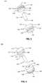
- FIG. 1is an exploded side view of a piston seal system, in accordance with an aspect of the present invention
- FIG. 2is an exploded bottom perspective view of the piston seal system of FIG. 1 , in accordance with an aspect of the present invention
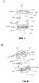
- FIG. 3is an exploded top perspective view of the piston seal system of FIG. 1 , in accordance with an aspect of the present invention
- FIG. 4is a side view of the piston seal system of FIG. 1 , in accordance with an aspect of the present invention
- FIG. 5is a perspective view of the piston seal system of FIG. 1 , in accordance with an aspect of the present invention.
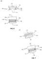
- FIG. 6is a side view of another piston seal system, in accordance with an aspect of the present invention.
- FIG. 7is a perspective view of the piston seal system of FIG. 6 , in accordance with an aspect of the present invention.
- FIG. 8is a side view of yet another piston seal system, in accordance with an aspect of the present invention.
- FIG. 9is a perspective view of the piston seal system of FIG. 8 , in accordance with an aspect of the present invention.
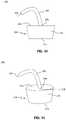
- FIG. 10is a side view of a stopper member and tube, in accordance with an aspect of the present invention.
- FIG. 11is a top perspective view of the stopper member and tube of FIG. 10 , in accordance with an aspect of the present invention.
- FIG. 12is a side view of another stopper member, in accordance with an aspect of the present invention.
- FIG. 13is a top perspective view of the stopper member of FIG. 12 , in accordance with an aspect of the present invention.
- FIG. 14is a side view of yet another stopper member, in accordance with an aspect of the present invention.
- FIG. 15is a perspective view of the stopper member of FIG. 14 , in accordance with an aspect of the present invention.
- FIG. 16is a side view of another stopper member, in accordance with an aspect of the present invention.
- FIG. 17is a perspective view of the stopper member of FIG. 16 , in accordance with an aspect of the present invention.
- FIG. 18is a side view of yet another stopper member, in accordance with an aspect of the present invention.
- FIG. 19is a perspective view of the stopper member of FIG. 18 , in accordance with an aspect of the present invention.
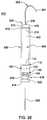
- FIG. 20is a perspective view of a pressure delivery device, in accordance with an aspect of the present invention.
- FIG. 21is a perspective view of another pressure delivery device, in accordance with an aspect of the present invention.
- FIG. 22is a side perspective view of a syringe system, in accordance with an aspect of the present invention.
- FIG. 23is a top perspective view of the syringe system of FIG. 22 , in accordance with an aspect of the present invention.
- FIG. 24is a side view of the syringe system of FIG. 22 with the piston seal system of FIG. 1 in a first position, in accordance with an aspect of the present invention
- FIG. 25is a side view of the syringe system of FIG. 22 with the piston seal system of FIG. 1 in a second position, in accordance with an aspect of the present invention
- FIG. 26is a partially exploded, side perspective view of a cartridge system with the piston seal system of FIG. 1 in a first position, in accordance with an aspect of the present invention
- FIG. 27is a side view of a cartridge system of FIG. 26 , in accordance with an aspect of the present invention.
- FIG. 28is a side view of a cartridge system of FIG. 26 with the piston seal system of FIG. 1 in a second position, in accordance with an aspect of the present invention.
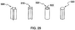
- FIG. 29is a side perspective view of a several alternative embodiments of a coupling member of the piston seal system of FIG. 1 , in accordance with an aspect of the present invention.
- syringe systemsGenerally stated, disclosed herein are syringe systems, piston seal systems, and stopper systems. Further, methods of assembling and using the syringe systems, piston seal systems, and stopper systems are discussed.
- proximal, distal, anterior, posterior, medial, lateral, superior and inferiorare defined by their standard usage for indicating a particular part of a device according to the relative disposition of the device with respect to a body or directional terms of reference.
- proximalmeans the portion of a device nearest the point of injection
- distalindicates the portion of the device farthest from the point of injection.
- anterioris a direction towards the front side of the device
- posteriormeans a direction towards the back side of the device
- medialmeans towards the midline of the device
- lateralis a direction towards the sides or away from the midline of the device
- superiormeans a direction above and “inferior” means a direction below another object or structure.
- the piston seal system 100may include a piston seal member 110 , a coupling member 122 , and a piston head member 130 .
- the coupling member 122may include a first end 124 and a second end 126 .
- the first end 124 of the coupling member 122may be secured to a second end 114 of the piston seal member 110 , as shown in FIGS. 4 and 5 .
- the second end 126 of the coupling member 122may be secured to the first end 132 of the piston head member 130 , as shown in FIGS.
- the coupling member 122may have, for example, a diameter that is smaller than the diameter of the seal member 110 and the head member 130 .
- the coupling member 122acts to create a pressure relief space between the second end 114 of the seal member 110 and the first end 132 of the head member 130 , as shown in FIGS. 4 and 5 .
- the coupling member 122may also act to create a space between the seal member 110 and head member 130 to trap any leaked fluid and prevent contamination of the medication being delivered.
- the coupling member 122may have, for example, a cross section with a polygonal, star, truss, donut, or any other shape.
- a coupling mechanism 500 with a star shape, a coupling mechanism 510 with an “X” shape, a coupling mechanism 520 with an “O” or donut shape including an opening 522 extending from the first end to the second end, and a coupling mechanism 530 with an octagon shapemay be used.
- the shape of the coupling member 122may be selected to provide support to the seal member 110 to prevent any angular shift or tilting of the seal member 110 when pressure is applied to the first end 112 .
- the piston seal system 100may be, for example, a three piece construct as shown in FIGS. 1-3 or alternatively may be a one piece construct as shown in FIGS. 4 and 5 .
- the three piece construct embodimentmay have a coupling member 122 with a first end 124 and a second end 126 .
- the first and second ends 124 , 126may be threaded to mate with corresponding threads in an opening in the second end 114 of the piston seal member 110 and the first end 132 of the piston head member 130 .
- the coupling member 122may be attached to the piston seal member 110 and the piston head member 130 by, for example, an adhesive, ultrasonic bonding, thermal melt, press fit, and the like.
- the one piece construct embodiment of the piston seal system 100may be a molded or an otherwise formed piston seal system 100 as shown in FIGS. 4 and 5 .
- Other configurations of the pieces of the piston seal system 100are also contemplated to form the piston seal system 100 , as shown in FIGS. 4 and 5 , with a piston seal member 110 spaced apart from a piston head member 130 .
- the piston seal member 110may include a first base portion at the first end 112 and a second base portion at the second end 114 .
- the piston seal member 110may also have, for example, at least one flange member, for example, a first flange member 116 and a second flange member 118 .
- the terms “flange member,” “flexible member,” “ribs,” and “rings”may be used interchangeably herein as they essentially refer to the same structure.
- the flange members 116 , 118are circumferential and have the same circumference as ends 112 , 114 to ensure continuous contact with the walls of the syringe and capture of liquid.
- the piston seal member 110may include a plurality of flange members 116 , 118 .
- the number of flange members 116 , 118may range from, for example, the minimum number of flange members 116 , 118 necessary to affect a seal and prevent fluid from passing through the piston seal member 110 to the maximum number of flange members 116 , 118 which still allow the piston seal member 110 to slide within a container, chamber, syringe, vial, or cartridge.
- the piston seal member 110may include, for example, approximately zero to four flange members 116 , 118 .
- the piston seal member 110may have a recess or groove 120 positioned between the flange members 116 , 118 .
- the second end 114 of the piston seal member 110may include an opening (not shown) for receiving the coupling member 122 .
- the first end 112 and second end 114may each be sized to be received within a syringe container, syringe chamber, or patch pump vial device (not shown).
- the first and second ends 112 , 114are sized to allow for movement while preventing the pressurized media used to inject the medication from passing by the piston seal member 110 and contaminating the sterile medication at the proximal end of the container, chamber, or vial.
- the at least one flange member 116 , 118may also be sized to engage the sidewall of the container, chamber, or vial to assist with preventing the pressurized media from passing by the piston seal member 110 and contaminating the sterile medication, as described in greater detail below.
- the piston seal member 110also provides a pressure relief area for the system 100 .
- the piston head member 130may include, for example, a first base portion 136 at the first end 132 and a second base portion 137 at the second end 134 .
- the first base portion 136may be, for example, thicker than the second base portion 137 .
- the piston head member 130may also include at least one flange member 138 and at least one recess or groove 140 positioned between the first base portion 136 at the first end 132 and the second base portion 137 at the second end 134 .
- the first base portion 136 and second base portion 137may be sized to be received within a syringe container, syringe chamber, or patch pump vial device (not shown) to prevent medication from passing to the distal end of the container, chamber, or vial during injection through a fluid pathway at the proximal end of the container, chamber, syringe, vial, or cartridge.
- the piston head member 130by preventing medication from passing to the distal end of the container, chamber, syringe, vial, or cartridge, maintains the sterility of the medication.
- the at least one flange member 138may also be sized to engage the sidewall of the container, chamber, or vial and assist with preventing the medication from passing by the piston head member 130 toward the distal end of the container, chamber, or vial to ensure the proper dosage of medication is delivered to the patient.
- the circumference and space between the at least one flange member 138 and first and second base portions 136 , 137allows for maximum contact between the at least one flange member 138 and the sidewall of the container, chamber, or vial.
- the piston head member 130may include a plurality of flange members 138 .
- the number of flange members 138may range from, for example, the minimum number of flange members 138 necessary to affect a seal and prevent fluid from passing through the piston head member 130 to the maximum number of flange members 138 which still allow the piston head member 130 to slide within a container, chamber, syringe, vial, or cartridge.
- the piston head member 130may include, for example, approximately two to five flange members 138 .
- the piston seal system 150is a two piece system.
- the piston seal system 150may include a piston seal member 110 and a piston head member 130 .
- the piston seal member 110 and piston head member 130may be the same as described above with reference to FIGS. 1-5 and will not be described again here for brevity sake.
- the seal member 110 and head member 130may be positioned in a container, chamber, or vial spaced apart to leave a pressure relief space between the seal member 110 and the head member 130 .
- a forcemay be applied on the seal member 110 which will in turn apply a force on the head member 130 to translate the head member 130 and deliver the medication to a patient.
- the force applied to the seal member 110may cause the second end 114 of the seal member 110 to directly contact the first end 132 of the head member 130 to move the head member 130 .
- the second end 114 of the seal member 110 and the first end 132 of the head member 130may have, for example, matching sizes and configurations to allow for the second end 114 to completely contact the first end 132 .
- the piston seal system 170is a one piece system.
- the piston seal system 170may include a piston seal member 110 including flanges 116 , 118 directly attached to a piston head member 130 including flanges 138 .
- the seal member 110 and head member 130may be the same as described above with reference to FIGS. 1-5 and will not be described again here for brevity sake.
- the base portion at the second end 114 of the seal member 110 and the base portion 136 of the head member 130may be, for example, secured together or alternatively be formed as a single piece creating an intermediate portion 176 .
- the intermediate portion 176may act as the barrier between the seal member 110 and the head member 130 .
- the piston seal system 170may be, for example, molded or formed as a unitary piece.
- the piston seal system 170may be used in a reusable container, chamber, or vial as it allows for the seal member 110 and head member 130 to move together enabling both injection from and filling of the container, chamber, or vial.
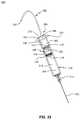
- FIGS. 10 and 11show one embodiment of a stopper system 200 .
- the stopper system 200may include a pressure delivery device 202 and a stopper member 210 .
- the stopper system 200may be secured into the end of a container, chamber, or vial, as described in greater detail below, to allow for delivery of a pressurized media to the distal end of the container, chamber, or vial.
- the pressure delivery device 202may include a first end 204 and a second end 206 .
- the first end 204may be coupled to a pressure delivery system for injection of a fluid into the container, chamber, or vial to activate delivery of a medication to a patient.
- the fluidmay be, for example, a liquid, gas, air, or the like.
- the second end 206may be coupled to the stopper member 210 at a first end 212 .
- the stopper member 210may include the first end 212 and a second end 214 opposite the first end 212 .
- the stopper member 210may also include a sidewall 216 extending between the first end 212 and the second end 214 .
- the sidewall 216may be straight, tapered, arced, or otherwise shaped to be secured within the opening in the container, chamber, or vial.
- the stopper member 210may also include an opening 218 , as shown in FIG. 11 .
- the opening 218may extend from the first end 212 to the second end 214 to receive the pressure delivery device 202 and allow for passage of the pressurized fluid.
- the stopper member 220may include a first end 212 , a second end 214 opposite the first end 212 , a sidewall 216 extending between the first end 212 and second end 214 , and a fitting member 230 .
- the fitting member 230may be secured to the first end 212 of the stopper member 220 at a coupling portion 222 .
- the fitting member 230may include a first end 232 , a receiving portion 234 , and a base portion 236 .
- the receiving portion 234may be sized to be secured to a pressure delivery device, such as devices 190 , 202 , as described in greater detail below with reference to FIGS. 20 and 21 .
- the base portion 236may be secured to the coupling portion 222 to secure the fitting member 230 to the first end 212 .
- the base portion 236may have, for example, a larger diameter than the receiving portion 234 .
- the stopper member 220may also include an opening 238 , as shown in FIG. 13 , which extends from the first end 232 of the fitting member 230 through to the second end 214 of the stopper member 220 .
- the opening 238allows for a pressurized media to pass through the stopper member 220 and into the container, chamber, or vial (not shown).
- the stopper system 240is a two piece system including a stopper member 210 and a fitting member 250 .
- the stopper member 210is of the type described above with reference to FIGS. 10 and 11 , which will not be described again here for brevity sake.
- the fitting member 250may include a first end 252 and a second end 254 opposite the first end 252 .
- the fitting member 250may also include a first receiving portion 256 , a second receiving portion 258 , and an intermediate portion 260 positioned between the first and second receiving portions 256 , 258 .
- the intermediate portion 260may have, for example, a larger diameter than the first and second receiving portions 256 , 258 and the receiving portions 256 , 258 may have, for example, the same diameter.
- the first receiving portion 256may be sized to be secured to a pressure delivery device, such as devices 190 , 202 , as described in greater detail below with reference to FIGS. 20 and 21 .
- the second receiving portion 258may be sized to be inserted into and secured to the opening 218 in the stopper member 210 .
- FIGS. 16 and 17show another stopper member 280 .
- the stopper member 280may include, for example, a first base portion at a first end 282 , a second base portion at a second end 284 , and a plurality of threads 286 extending between the first and second base portions on an exterior surface of the stopper member 280 .
- the plurality of threads 286may correspond to a plurality of threads (not shown) in the distal end of a container, chamber, or vial for securing the stopper member 280 to a container, chamber, or vial for administering a medication.
- the stopper member 280may also include an opening 288 extending from the first end 282 to the second end 284 at, for example, a generally center point of the stopper member 280 .
- the opening 288may be sized to receive a pressure delivery device, such as devices 190 , 202 , as described in greater detail below with reference to FIGS. 20 and 21 .
- the stopper system 290may include a stopper member 280 and a fitting member 250 .
- the stopper member 280may be of the type described above with reference to FIGS. 16 and 17 and the fitting member 250 may be of the type described above with reference to FIGS. 14 and 15 .
- the stopper member 280 and fitting member 250will not be described again here in detail for brevity sake.
- the first receiving portion 256 of the fitting member 250may be sized to be secured to a pressure delivery device, such as devices 190 , 202 , as described in greater detail below with reference to FIGS. 20 and 21 .
- the second receiving portion 258 of the fitting member 250may be sized to be inserted into and secured to the opening 288 in the stopper member 280 .
- the fitting member 250may include, for example, a plurality of threads (not shown) positioned on the exterior surface of the second receiving portion 258 .
- the plurality of threads on the second receiving portion 258may correspond to a plurality of threads (not shown) on the interior surface of the opening 288 for securing the fitting member 250 to the stopper member 280 .
- Alternative securement meansfor example, adhesives, one piece molding, press-fit, and the like are also contemplated to secure the fitting member 250 to the stopper member 280 .
- FIG. 20shows the pressure delivery device 202 .
- the pressure delivery device 202may include a first end 204 and a second end 206 .
- the pressure delivery device 202may be, for example, a tube or other hollow elongated structure to allow for a pressurized media to pass from the first end 204 to the second end 206 .
- the first end 204may be sized to couple to a pressure delivery system (not shown) to deliver a pressurized fluid to a syringe container, chamber, or vial (not shown) for delivery of a medication to a patient.
- the second end 206may be sized to be secured to a stopper member 210 , 220 , 240 , 280 , 290 either directly or using a separate or integral fitting member 230 , 250 .
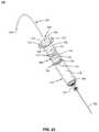
- the pressure delivery device 190may include a first end 204 , a second end 206 , and a staking needle 208 .
- the pressure delivery device 190may be, for example, a tube or other hollow structure to allow for fluid to pass from the first end 204 to the second end 206 and then through the staking needle 208 to the syringe container, chamber, or vial (not shown).
- the staking needle 208may be secured to the second end 206 .
- the staking needle 208may be, for example, inserted directly into the stopper member 210 , 280 without the need for the stopper member to include the opening 218 , 288 .
- Alternative pressure delivery devices 202 , 190are also contemplated for transferring a pressurized media from a pressure delivery system to a syringe container, chamber, or vial to move a piston seal system, such as systems 100 , 150 , or 170 , to deliver a medication to a patient.
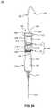
- the injection system 300may include a container 310 , a fluid pathway 322 , a stopper system 200 , and a syringe piston seal system 100 .
- the container 310may include a first end for receiving the stopper system 200 and a second end for receiving the fluid pathway 322 .
- the syringe piston seal system 100may be sized to fit into an opening 316 in the container 310 .
- the exterior surface of the piston seal system 100is sized to engage the interior surface or walls of the container 310 .
- the container 310may be in, for example, a syringe, vial, or other container used for administering medication or fluids to a patient.
- the container 310may be made of, for example, plastic, glass, metal, or any other material suitable for storing and delivering medication or fluids to a patient.
- the first end of the container 310may include, for example, a flange 312 surrounding the opening 316 .
- the second end of the container 310may include an attachment portion 314 for receiving a fluid pathway 322 .
- the fluid pathway 322may be, for example, a needle, cannula, or other device for delivering medication to a patient.
- the container 310includes a cavity or chamber 318 , 320 extending from the opening 316 to the attachment portion 314 .
- the attachment portion 314couples the chamber 318 , 320 to the fluid pathway 322 allowing fluid to pass from the chamber 318 , 320 to the fluid pathway 322 .
- the container 310may have, for example, any shape which is desirable for storing and delivering the medication or fluids to a patient and the syringe piston seal system 100 may have a shape to correspond to the shape of the opening 316 in the container 310 .
- the injection system 300may be assembled by inserting a fluid pathway 322 into the container 310 .
- the fluid pathway 322be capped to ensure medication is not released from the fluid pathway 322 prior to the medication being administered.
- the chamber 318 , 320may be filled with the desired amount of medication 304 by known filling methods. Once the desired amount of medication 304 is contained within the chamber 318 , 320 , the syringe piston seal system 100 may be inserted into the opening 316 .
- the chamber 318 , 320is divided into a first chamber 318 at the second end of the container 310 and a second chamber 320 at the first end of the container 310 .
- the chamber 318may be filled by known methods with the desired amount of medication 304 after the syringe piston seal system 100 is inserted into the opening 316 in the container 310 .
- the syringe piston seal system 100may be made of, for example, any material that allows for sliding movement of the system 100 within the container 310 while maintaining separation between the pressurized fluid 302 and medication 304 .
- the material of the syringe piston seal system 100may be selected based on the medication 304 being injected and pressurized fluid 302 being used to ensure that no contamination of the sterilize medication 304 occurs. Although the syringe piston seal system 100 is shown, the syringe piston seal systems 150 , 170 , and other combinations thereof may also be used.
- a stopper system 200may be secured to the distal end of the container 310 .
- the stopper system 200may be inserted into the container 310 , for example, so that the second end 214 of the stopper system 200 directly contacts the first end 112 of the piston seal member 110 .
- the stopper system 200may be secured by inserting the stopper member 210 into the opening 316 to close the chamber 320 .
- the stopper system 200is shown, other stopper systems may also be used including, for example, stopper members 220 , 280 , and combinations thereof.
- the stopper system 200may also include a pressure delivery device 202 which may be coupled to a pressure delivery system at a first end 204 and to the stopper member 210 at a second end 206 .
- the piston seal member 110 and the piston head member 130are each sized to prevent the pressurized media 302 from leaking into the medication 304 , thus providing a barrier to isolate the pressurized media 302 from the medication 304 .
- the space created around the coupling member 122may trap the fluid 302 , 304 from escaping and contaminating the medication 304 .
- the flange members 116 , 118 and grooves 120 of the seal member 110 and the flange members 138 and recesses 140 of the head member 130may also act to assist with trapping any fluid 302 , 304 that may leak and prevent the leaked pressurized fluid 302 from contaminating the medication 304 .
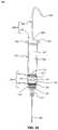
- FIG. 24illustrates the position of the piston seal system 100 when the pressurized media 302 begins to be pumped into the chamber 318 .
- FIG. 25shows the position of the piston seal system 100 after all of the medication 304 is delivered to the patient.
- the injection system 400may include a container 410 , a fluid pathway 430 , a stopper system 200 , and a piston seal system 100 .
- the container 410may include a first end for receiving the stopper system 200 and a second end for receiving the fluid pathway 430 .
- the piston seal system 100may be sized to fit into an opening 416 in the container 410 .
- the exterior surface of the piston seal system 100is sized to engage the interior surface or walls of the container 410 .
- the container 410may be in, for example, a cartridge, vial, syringe, or other container used for administering medication or fluids to a patient.
- the container 410may be made of, for example, plastic, glass, metal, or any other material suitable for storing and delivering medication or fluids to a patient.
- the container 410may include, for example, a first end 412 and a second end 414 .
- the second end 414may include an attachment portion 418 for receiving a fluid pathway 430 .
- the attachment portion 418may include, for example, a neck portion 420 and a flange portion 422 .
- the neck portion 420may have, for example, a smaller diameter than the container 410 and the flange portion 422 .
- the fluid pathway 430may be, for example, a needle, cannula, or other device for delivering medication to a patient.
- the container 410includes a chamber or cavity 424 extending from the opening 416 to the attachment portion 418 .
- the attachment portion 418couples the chamber 424 to the fluid pathway 430 allowing fluid to pass from the chamber 424 to the fluid pathway 430 .
- the container 410may have, for example, any shape which is desirable for storing and delivering the medication or fluids to a patient and the piston seal system 100 may have a shape to correspond to the shape of the opening 416 in the container 410 .
- the injection system 400may be assembled by inserting a fluid pathway 430 into the container 410 .
- the fluid pathway 430be capped to ensure medication is not released from the fluid pathway 430 prior to the medication being administered and to prevent accidental contacts with the fluid pathway 430 .
- the chamber 424may be filled with the desired amount of medication by known filling methods. Once the desired amount of medication is transported into the chamber 424 , the piston seal system 100 may be inserted into the opening 416 . When the piston seal system 100 is inserted into the chamber 424 of the container 410 it is positioned at the first end of the container 410 , as shown in FIG. 26 .
- the chamber 424may be filled by known methods with the desired amount of medication after the piston seal system 100 is inserted into the opening 416 in the container 410 .
- the piston seal system 100may be made of, for example, any material that allows for sliding movement of the system 100 within the container 410 while maintaining separation between the medication and the pressurized fluid injected into the container 410 by the pressure delivery device 202 .
- the material of the piston seal system 100may be selected based on the medication being injected and pressurized fluid being used to ensure that no contamination of the sterilize medication occurs.
- the piston seal system 100is shown, the piston seal systems 150 , 170 , and other combinations thereof may also be used.
- a stopper system 200may be secured to the distal end of the container 410 .
- the stopper system 200may be inserted into the container 410 , for example, so that the second end 214 of the stopper system 200 directly contacts the first end 112 of the piston seal member 110 , as shown in FIG. 26 .
- the stopper system 200may be secured by inserting the stopper member 210 into the opening 416 to close the chamber 424 .
- the stopper system 200is shown, other stopper systems may also be used including, for example, stopper members 220 , 280 , and combinations thereof.
- the stopper system 200may also include a pressure delivery device 202 which may be coupled to a pressure delivery system at a first end 204 and to the stopper member 210 at a second end 206 .
- the system 400may be used for an injection.
- the injection system 400may be used for an injection by turning on the connected pressure delivery device to start the flow of a pressurized media 402 through the pressure delivery device 202 and into the chamber 424 .
- forceis applied to the first end 112 of the piston seal member 110 by the pressurized media 402 .
- the injection system 400may include, for example, at least one one-way vent to allow for the release of air or gas from the container 410 if the pressurized media 402 is a liquid.
- the piston seal member 110 and the piston head member 130are each sized to prevent the pressurized media 402 from leaking into the medication 404 , thus providing a barrier to isolate the pressurized media 402 from the medication 404 .
- the space created around the coupling member 122may trap the fluid 402 , 404 from escaping and contaminating the medication 404 .
- the flange members 116 , 118 and grooves 120 of the seal member 110 and the flange members 138 and recesses 140 of the head member 130may also act to assist with trapping any fluid 402 , 404 that may leak and prevent the leaked pressurized fluid 402 from contaminating the medication 404 .
- the piston seal system 100begins to move toward the second or proximal end 414 of the container 410 , as shown in FIG. 27 .
- the piston seal system 100moves, the fluid resistance in the fluid pathway 430 is overcome and the medication 404 is forced out of the fluid pathway 430 for delivery to the patient.
- the position of the piston seal system 100 after all of the medication 404 is delivered to the patientis shown in FIG. 28 .
- injection systemsmay include more or fewer components or features than the embodiments as described and illustrated herein.
- the components and features of FIGS. 1-5 , FIGS. 6-7 , and FIGS. 8-9may all be used interchangeably and in alternative combinations as would be modified or altered by one of skill in the art.
- the components and features of FIGS. 10-11 , FIGS. 12-13 , FIGS. 14-15 , FIGS. 16-17 , and FIGS. 18-19may all be used interchangeably and in alternative combinations as would be modified or altered by one of skill in the art. Accordingly, this detailed description of the currently-preferred embodiments is to be taken as illustrative, as opposed to limiting of the invention.
- a method or device that “comprises,” “has,” “includes,” or “contains” one or more steps or elementspossesses those one or more steps or elements, but is not limited to possessing only those one or more steps or elements.
- a step of a method or an element of a device that “comprises,” “has,” “includes,” or “contains” one or more featurespossesses those one or more features, but is not limited to possessing only those one or more features.
- a device or structure that is configured in a certain wayis configured in at least that way, but may also be configured in ways that are not listed.
- a piston head membermay be referred to as “a piston”
- pressurized fluidmay be referred to as a “first fluid”
- medicationmay be referred to as a “second fluid”
- flangesmay be referred to as “circumferential rings.”
Landscapes
- Health & Medical Sciences (AREA)
- Engineering & Computer Science (AREA)
- Animal Behavior & Ethology (AREA)
- Life Sciences & Earth Sciences (AREA)
- Veterinary Medicine (AREA)
- Public Health (AREA)
- Vascular Medicine (AREA)
- Anesthesiology (AREA)
- Biomedical Technology (AREA)
- Heart & Thoracic Surgery (AREA)
- Hematology (AREA)
- General Health & Medical Sciences (AREA)
- General Engineering & Computer Science (AREA)
- Mechanical Engineering (AREA)
- Chemical & Material Sciences (AREA)
- Combustion & Propulsion (AREA)
- Physics & Mathematics (AREA)
- Fluid Mechanics (AREA)
- Infusion, Injection, And Reservoir Apparatuses (AREA)
Abstract
Description
Claims (21)
Priority Applications (1)
| Application Number | Priority Date | Filing Date | Title |
|---|---|---|---|
| US15/048,366US10869966B2 (en) | 2015-02-20 | 2016-02-19 | Syringe systems, piston seal systems, stopper systems, and methods of use and assembly |
Applications Claiming Priority (2)
| Application Number | Priority Date | Filing Date | Title |
|---|---|---|---|
| US201562118924P | 2015-02-20 | 2015-02-20 | |
| US15/048,366US10869966B2 (en) | 2015-02-20 | 2016-02-19 | Syringe systems, piston seal systems, stopper systems, and methods of use and assembly |
Publications (2)
| Publication Number | Publication Date |
|---|---|
| US20160243309A1 US20160243309A1 (en) | 2016-08-25 |
| US10869966B2true US10869966B2 (en) | 2020-12-22 |
Family
ID=56689187
Family Applications (1)
| Application Number | Title | Priority Date | Filing Date |
|---|---|---|---|
| US15/048,366Active2036-05-30US10869966B2 (en) | 2015-02-20 | 2016-02-19 | Syringe systems, piston seal systems, stopper systems, and methods of use and assembly |
Country Status (9)
| Country | Link |
|---|---|
| US (1) | US10869966B2 (en) |
| EP (1) | EP3258995B1 (en) |
| JP (1) | JP7066411B2 (en) |
| KR (1) | KR102541205B1 (en) |
| CN (1) | CN107530502B (en) |
| AU (1) | AU2016219904B2 (en) |
| CA (1) | CA2977060C (en) |
| IL (2) | IL254034A0 (en) |
| WO (1) | WO2016134221A1 (en) |
Families Citing this family (12)
| Publication number | Priority date | Publication date | Assignee | Title |
|---|---|---|---|---|
| EP3093035A1 (en)* | 2015-05-13 | 2016-11-16 | Sanofi-Aventis Deutschland GmbH | Injection device for delivery of a liquid medicament |
| GB2556616B (en)* | 2016-07-21 | 2019-09-25 | Cipher Surgical Ltd | Scope assembly |
| EP3354303B1 (en)* | 2017-01-31 | 2020-01-08 | Société Industrielle de Sonceboz S.A. | Drug delivery system |
| US10863737B2 (en)* | 2017-05-22 | 2020-12-15 | Drobot Biotechnology Limited Company | Culture container, and system and method of transferring a cultured organism between culture containers |
| MA49838A (en)* | 2017-08-09 | 2020-06-17 | Amgen Inc | DRUG DELIVERY SYSTEM WITH CHAMBER HYDRAULIC-PNEUMATIC PRESSURE |
| USD900307S1 (en)* | 2018-01-26 | 2020-10-27 | Treble Innovations, Llc | Syringe plunger seal and barrel |
| CN110375067B (en)* | 2019-06-25 | 2024-06-14 | 北京北分瑞利分析仪器(集团)有限责任公司 | Piston sealing structure applied to injector |
| CN117379640A (en) | 2019-07-02 | 2024-01-12 | 里珍纳龙药品有限公司 | Autoinjector and associated method of use |
| EP3881877B1 (en)* | 2020-03-17 | 2024-06-12 | Becton Dickinson France | Stopper for a medical injection device |
| US20210402097A1 (en)* | 2020-06-26 | 2021-12-30 | Aktivax, Inc. | Auto-injector with uniform pressure exertion of a primary container |
| EP3967341B1 (en)* | 2020-09-10 | 2025-07-09 | Fenwal, Inc. | Syringe with syringe closure |
| AU2022343098A1 (en)* | 2021-09-07 | 2024-03-21 | Anne Marie BREE | Linking structure and container assembly to facilitate liquid transfer from a donor container to a recipient container |
Citations (120)
| Publication number | Priority date | Publication date | Assignee | Title |
|---|---|---|---|---|
| US2680439A (en) | 1948-09-08 | 1954-06-08 | Arnold K Sutermeister | High-pressure injection device |
| US3028862A (en) | 1959-07-02 | 1962-04-10 | American Cyanamid Co | Hypodermic syringe |
| US3075525A (en) | 1959-07-15 | 1963-01-29 | Robert K Mcconnaughey | Venting closures and separators for hypodermic syringes |
| US3460534A (en) | 1966-11-25 | 1969-08-12 | Robert B Black | Aspirating cartridge syringe with gas actuation |
| US4231494A (en) | 1979-03-22 | 1980-11-04 | Greenwood David L | Syringe adaptor assembly |
| US4424057A (en)* | 1982-04-01 | 1984-01-03 | House Hugh A | Wet-dry syringe |
| US4437859A (en) | 1981-08-03 | 1984-03-20 | Drs Infusion Systems, Inc. | Hydraulic syringe drive |
| US4505701A (en) | 1982-05-17 | 1985-03-19 | Navato Jose R | Automatic parenteral infusion apparatus |
| JPS61164564A (en) | 1985-01-10 | 1986-07-25 | ジヨゼ・ア−ル・ナヴオト | Automatic solution injector |
| US4861340A (en) | 1988-10-17 | 1989-08-29 | Cordis Corporation | Hand-held pneumatic power assisted syringe |
| US5425715A (en) | 1993-08-05 | 1995-06-20 | Survival Technology, Inc. | Reloadable injector |
| JPH07299141A (en) | 1994-02-18 | 1995-11-14 | Takeda Chem Ind Ltd | Refilled syringe |
| US5586975A (en)* | 1994-02-18 | 1996-12-24 | Takeda Chemical Industries. Ltd. | Air and liquid tight container with a slidable gasket |
| US5616132A (en) | 1995-06-09 | 1997-04-01 | Subot, Inc. | Injection device |
| US5865803A (en) | 1997-05-19 | 1999-02-02 | Major; Miklos | Syringe device having a vented piston |
| US6045534A (en) | 1997-10-27 | 2000-04-04 | Sarcos, Inc. | Disposable fluid injection module |
| US6186982B1 (en) | 1998-05-05 | 2001-02-13 | Elan Corporation, Plc | Subcutaneous drug delivery device with improved filling system |
| US6193695B1 (en) | 2000-01-14 | 2001-02-27 | Wayland J. Rippstein, Jr. | Disposable safety syringe having a retractable needle |
| US20010021828A1 (en)* | 1999-12-20 | 2001-09-13 | Fischer Dan E. | Hydraulic syringe and method of manufacture |
| DE10015616A1 (en) | 2000-03-29 | 2001-10-04 | Peter Mueller | Injection syringe for use in dentistry, comprises injection tube, an ampoule, a press member which controls the substance flow, and a work unit which acts on the ampoule |
| JP2001321437A (en) | 2000-05-17 | 2001-11-20 | Yoshida Dental Mfg Co Ltd | Automatic injector |
| US6500150B1 (en) | 1997-06-16 | 2002-12-31 | Elan Pharma International Limited | Pre-filled drug-delivery device and method of manufacture and assembly of same |
| US6511459B1 (en) | 2000-09-29 | 2003-01-28 | Mallinckrodt Inc. | Syringe plunger having an improved sealing ability |
| CN1429125A (en) | 2000-05-15 | 2003-07-09 | 阿雷斯贸易股份有限公司 | Injection device |
| US6595956B1 (en) | 1998-03-23 | 2003-07-22 | Joseph Gross | Drug delivery device |
| US6673035B1 (en) | 1999-10-22 | 2004-01-06 | Antares Pharma, Inc. | Medical injector and medicament loading system for use therewith |
| US6682504B2 (en) | 2000-03-23 | 2004-01-27 | Antares Pharma, Inc. | Single use disposable jet injector |
| US20040073169A1 (en) | 2000-09-28 | 2004-04-15 | Shai Amisar | Constant pressure apparatus for the administration of fluids intravenously |
| WO2004067067A1 (en) | 2003-01-24 | 2004-08-12 | Alza Corporation | Pneumatic powered autoinjector |
| CN2675156Y (en) | 2004-02-25 | 2005-02-02 | 孟庆义 | Resuscitation drug administration needle for trachea puncture by way of circothyroid membrane |
| US20050043689A1 (en) | 2003-08-19 | 2005-02-24 | Lite-On It Corporation | Sealing piston for syringe |
| US20050209562A1 (en) | 2002-02-08 | 2005-09-22 | Yong-Nyun Kim | Liquid supply apparatus |
| US6960184B2 (en) | 1998-12-18 | 2005-11-01 | Biovalve Technologies, Inc. | Injection devices |
| WO2006083876A2 (en) | 2005-02-01 | 2006-08-10 | Intelliject, Llc | Devices, systems, and methods for medicament delivery |
| US7104971B2 (en) | 2000-05-22 | 2006-09-12 | Pharmacia Ab | Medical device |
| US20070185437A1 (en) | 2006-02-03 | 2007-08-09 | Boris Goldenberg | Needle-free syringe and the injection procedure |
| WO2007131367A1 (en) | 2006-05-15 | 2007-11-22 | Tecpharma Licensing Ag | Device for administering a fluid product |
| WO2008064092A2 (en) | 2006-11-21 | 2008-05-29 | Intelliject, Inc. | Devices, systems and methods for medicament delivery |
| WO2008091838A2 (en) | 2007-01-22 | 2008-07-31 | Intelliject, Inc. | Medical injector with compliance tracking and monitoring |
| US7416540B2 (en) | 2004-11-22 | 2008-08-26 | Intelliject, Llc | Devices systems and methods for medicament delivery |
| WO2008103997A2 (en) | 2007-02-23 | 2008-08-28 | Bioject Inc. | Needle-free injection devices and drug delivery systems therefor |
| US7449012B2 (en) | 2004-08-06 | 2008-11-11 | Meridian Medical Technologies, Inc. | Automatic injector |
| US20090082737A1 (en) | 2006-04-21 | 2009-03-26 | Benjamin Bobst | Syringe Cylinder |
| US20090118680A1 (en) | 2007-11-05 | 2009-05-07 | Peter Goldbrunner | Automatic gas filling consumable |
| US7648482B2 (en) | 2004-11-22 | 2010-01-19 | Intelliject, Inc. | Devices, systems, and methods for medicament delivery |
| US7648483B2 (en) | 2004-11-22 | 2010-01-19 | Intelliject, Inc. | Devices, systems and methods for medicament delivery |
| US7654983B2 (en) | 2001-11-09 | 2010-02-02 | Johnson And Johnson Vision Care, Inc. | Pneumatic powered autoinjector |
| US7731686B2 (en) | 2005-02-01 | 2010-06-08 | Intelliject, Inc. | Devices, systems and methods for medicament delivery |
| US7824373B2 (en) | 2003-05-28 | 2010-11-02 | Ducksoo Kim | Self-contained power-assisted syringe |
| WO2010138703A1 (en) | 2009-05-29 | 2010-12-02 | Wilson-Cook Medical Inc. | Systems and methods for delivering therapeutic agents |
| US7857167B1 (en) | 2005-08-29 | 2010-12-28 | Anthony Scott Hollars | Compressed gas cartridge permeation dispenser having a predictable permeation rate |
| WO2011023629A1 (en) | 2009-08-27 | 2011-03-03 | Sanofi-Aventis Deutschland Gmbh | Injector device |
| US20110060291A1 (en) | 2009-09-08 | 2011-03-10 | Al.Chi.Mi.A. S.R.L. | Device for injecting into an eyeball a sterile liquid selected from amongst perfluorocarbons |
| US20110091331A1 (en) | 2001-04-27 | 2011-04-21 | Hydrocision, Inc. | High pressure pumping cartridges for medical and surgical pumping and infusion applications |
| US7947017B2 (en) | 2004-11-22 | 2011-05-24 | Intelliject, Inc. | Devices, systems and methods for medicament delivery |
| US8021344B2 (en) | 2008-07-28 | 2011-09-20 | Intelliject, Inc. | Medicament delivery device configured to produce an audible output |
| WO2011133823A1 (en) | 2010-04-21 | 2011-10-27 | Abbott Biotechnology Ltd. | Wearable automatic injection device for controlled delivery of therapeutic agents |
| EP2401012A1 (en) | 2009-02-27 | 2012-01-04 | Lifescan, Inc. | Drug delivery system |
| WO2012045836A2 (en) | 2010-10-08 | 2012-04-12 | Sanofi-Aventis Deutschland Gmbh | Reusable engine for an auto-injector |
| US8172797B2 (en) | 2007-10-10 | 2012-05-08 | Shl Group Ab | Medical delivery device |
| US8206360B2 (en) | 2005-02-01 | 2012-06-26 | Intelliject, Inc. | Devices, systems and methods for medicament delivery |
| US20120191102A1 (en)* | 2009-09-29 | 2012-07-26 | Terumo Kabushiki Kaisha | Medicine injection device and method |
| US8231573B2 (en) | 2005-02-01 | 2012-07-31 | Intelliject, Inc. | Medicament delivery device having an electronic circuit system |
| WO2012145752A2 (en) | 2011-04-21 | 2012-10-26 | Abbott Laboratories | Wearable automatic injection device for controlled administration of therapeutic agents |
| US8303535B2 (en) | 2008-09-10 | 2012-11-06 | Hoffman-La Roche Inc. | Delivery device for use with a therapeutic drug |
| US8308697B2 (en) | 2007-03-07 | 2012-11-13 | The Medical House Limited | Autoinjector |
| US8313463B2 (en) | 2004-05-28 | 2012-11-20 | Cilag Gmbh International | Injection device |
| US8343110B2 (en) | 2004-05-28 | 2013-01-01 | Cilag Gmbh International | Injection device |
| US8361026B2 (en) | 2005-02-01 | 2013-01-29 | Intelliject, Inc. | Apparatus and methods for self-administration of vaccines and other medicaments |
| US8361054B2 (en) | 2008-12-23 | 2013-01-29 | Cook Medical Technologies Llc | Apparatus and methods for containing and delivering therapeutic agents |
| JP2013063276A (en) | 2003-04-23 | 2013-04-11 | Valeritas Inc | Hydraulic operating type pump for long-duration drug administration |
| US20130274677A1 (en) | 2010-12-21 | 2013-10-17 | Sanofi-Aventis Deutschland Gmbh | Front End for an Auto-Injector |
| WO2013182858A1 (en) | 2012-06-07 | 2013-12-12 | Consort Medical Plc | Improved syringe |
| US8627816B2 (en) | 2011-02-28 | 2014-01-14 | Intelliject, Inc. | Medicament delivery device for administration of opioid antagonists including formulations for naloxone |
| EP2686036A1 (en) | 2011-03-18 | 2014-01-22 | AbbVie Inc. | Systems, devices and methods for assembling automatic injection devices and sub-assemblies thereof |
| US8636704B2 (en) | 2009-04-29 | 2014-01-28 | Abbvie Biotechnology Ltd | Automatic injection device |
| US8668670B2 (en) | 2004-06-23 | 2014-03-11 | Abbvie Biotechnology Ltd | Automatic injection devices |
| US8679061B2 (en) | 2006-06-30 | 2014-03-25 | Abbvie Biotechnology Ltd | Automatic injection device |
| WO2014059444A2 (en) | 2012-10-12 | 2014-04-17 | Eli Lilly And Company | Chemical engines and methods for their use, especially in the injection of highly viscous fluids |
| US20140114248A1 (en) | 2012-10-24 | 2014-04-24 | Nuance Designs, LLC | Power pack for an autoinjector |
| US8708968B2 (en) | 2011-01-24 | 2014-04-29 | Abbvie Biotechnology Ltd. | Removal of needle shields from syringes and automatic injection devices |
| US20140128840A1 (en) | 2011-03-29 | 2014-05-08 | Abbvie Inc. | Shroud Deployment in Automatic Injection Devices |
| US8758301B2 (en) | 2009-12-15 | 2014-06-24 | Abbvie Biotechnology Ltd | Firing button for automatic injection device |
| US20140207073A1 (en) | 2011-09-22 | 2014-07-24 | Abbvie Inc | Automatic Injection Device |
| US20140276411A1 (en) | 2013-03-14 | 2014-09-18 | Medrad, Inc. | Fluid Delivery System and Method of Fluid Delivery to a Patient |
| US20140276451A1 (en) | 2013-03-12 | 2014-09-18 | Medrad, Inc. | Constant force syringe |
| US20140276614A1 (en)* | 2013-03-14 | 2014-09-18 | MRI Interventions, Inc. | Substance delivery devices, systems and methods |
| US20140276415A1 (en)* | 2013-03-15 | 2014-09-18 | Carefusion 303, Inc. | Infusion system with dual-chambered reservoir |
| EP2820640A1 (en) | 2012-03-02 | 2015-01-07 | AbbVie Inc. | Automatic injection training device |
| US8932252B2 (en) | 2005-02-01 | 2015-01-13 | Kaleo, Inc. | Medical injector simulation device |
| US8939943B2 (en) | 2011-01-26 | 2015-01-27 | Kaleo, Inc. | Medicament delivery device for administration of opioid antagonists including formulations for naloxone |
| US8992476B2 (en) | 2011-09-22 | 2015-03-31 | Abbvie Inc. | Automatic injection device |
| US9084849B2 (en) | 2011-01-26 | 2015-07-21 | Kaleo, Inc. | Medicament delivery devices for administration of a medicament within a prefilled syringe |
| US9101744B2 (en) | 2009-05-29 | 2015-08-11 | Cook Medical Technologies Llc | Systems and methods for delivering therapeutic agents |
| US9119920B2 (en) | 2011-01-17 | 2015-09-01 | Owen Mumford Limited | Automatic injection device with pneumatic damping |
| WO2015172686A1 (en) | 2014-05-14 | 2015-11-19 | 苏州大学张家港工业技术研究院 | Pneumatic accumulating needleless syringe |
| USD744005S1 (en) | 2014-12-30 | 2015-11-24 | Abbvie Inc. | Pump |
| US9265887B2 (en) | 2011-01-24 | 2016-02-23 | Abbvie Biotechnology Ltd. | Automatic injection devices having overmolded gripping surfaces |
| US20160199579A1 (en) | 2011-01-10 | 2016-07-14 | Zogenix, Inc. | Needle free injectors |
| WO2016154427A2 (en) | 2015-03-24 | 2016-09-29 | Kaleo, Inc. | Devices and methods for delivering a lyophilized medicament |
| US20160279323A1 (en) | 2013-10-28 | 2016-09-29 | Consort Medical Plc | Medicament delivery device |
| US20160303327A1 (en) | 2013-03-25 | 2016-10-20 | Carebay Europe Ltd. | Power Pack Lock |
| EP3089774A1 (en) | 2013-12-31 | 2016-11-09 | AbbVie Inc. | Devices and methods for delivering a benefical agent to a user |
| EP3089772A2 (en) | 2013-12-31 | 2016-11-09 | AbbVie Inc. | Pump, motor and assembly for beneficial agent delivery |
| US9517307B2 (en) | 2014-07-18 | 2016-12-13 | Kaleo, Inc. | Devices and methods for delivering opioid antagonists including formulations for naloxone |
| US20160361496A1 (en) | 2015-06-15 | 2016-12-15 | Nuance Designs Of Ct, Llc | Autoinjector |
| US9522235B2 (en) | 2012-05-22 | 2016-12-20 | Kaleo, Inc. | Devices and methods for delivering medicaments from a multi-chamber container |
| US9542826B2 (en) | 2012-12-27 | 2017-01-10 | Kaleo, Inc. | Devices, systems and methods for locating and interacting with medicament delivery systems |
| US9550025B2 (en) | 2010-03-25 | 2017-01-24 | New Injection Systems Ltd. | Injector |
| US20170072134A1 (en) | 2015-09-16 | 2017-03-16 | Tyler G. Fish | Medical infusion pump for sequentially injecting solutions from multiple syringes |
| US9636460B1 (en) | 2016-12-28 | 2017-05-02 | Creare Llc | Pneumatic autoinjector with automated mixing |
| US20170182242A1 (en) | 2015-12-27 | 2017-06-29 | Abbvie Inc. | Wearable Automatic Injection Device and Related Methods of Use |
| US9731080B2 (en) | 2005-04-06 | 2017-08-15 | Cilag Gmbh International | Injection device |
| WO2017181297A1 (en) | 2016-04-21 | 2017-10-26 | Tecpharma Licensing Ag | Gas release device for use in an injection apparatus |
| US20170304548A1 (en) | 2014-10-09 | 2017-10-26 | Carebay Europe Ltd. | A Power Pack Assembly for a Medicament Delivery Device |
| US20170312457A1 (en) | 2016-05-02 | 2017-11-02 | Nuance Designs Of Ct, Llc | Mobile imaging modality for medical devices |
| US20170348488A1 (en) | 2011-09-09 | 2017-12-07 | Merck Patent Gmbh | Auto injector with separate needle injection |
| US20180008775A1 (en) | 2016-07-07 | 2018-01-11 | Carebay Europe Ltd. | Drug Delivery Device with Pneumatic Power Pack |
| US9867931B2 (en) | 2013-10-02 | 2018-01-16 | Cook Medical Technologies Llc | Therapeutic agents for delivery using a catheter and pressure source |
| WO2018013493A1 (en) | 2016-07-11 | 2018-01-18 | Heron Therapeutics, Inc. | Powered delivery device |
Family Cites Families (3)
| Publication number | Priority date | Publication date | Assignee | Title |
|---|---|---|---|---|
| JP2001025506A (en)* | 1999-05-10 | 2001-01-30 | Material Eng Tech Lab Inc | Medicinal liquid-containing syringe |
| AUPQ867900A0 (en)* | 2000-07-10 | 2000-08-03 | Medrad, Inc. | Medical injector system |
| US20080147007A1 (en)* | 2006-12-19 | 2008-06-19 | Toby Freyman | Delivery device with pressure control |
- 2016
- 2016-02-19CNCN201680022806.8Apatent/CN107530502B/enactiveActive
- 2016-02-19CACA2977060Apatent/CA2977060C/enactiveActive
- 2016-02-19AUAU2016219904Apatent/AU2016219904B2/ennot_activeCeased
- 2016-02-19KRKR1020177024916Apatent/KR102541205B1/enactiveActive
- 2016-02-19EPEP16753118.5Apatent/EP3258995B1/enactiveActive
- 2016-02-19JPJP2017544004Apatent/JP7066411B2/enactiveActive
- 2016-02-19USUS15/048,366patent/US10869966B2/enactiveActive
- 2016-02-19WOPCT/US2016/018609patent/WO2016134221A1/ennot_activeCeased
- 2017
- 2017-08-17ILIL254034Apatent/IL254034A0/enunknown
- 2022
- 2022-03-13ILIL291320Apatent/IL291320A/enunknown
Patent Citations (212)
| Publication number | Priority date | Publication date | Assignee | Title |
|---|---|---|---|---|
| US2680439A (en) | 1948-09-08 | 1954-06-08 | Arnold K Sutermeister | High-pressure injection device |
| US3028862A (en) | 1959-07-02 | 1962-04-10 | American Cyanamid Co | Hypodermic syringe |
| US3075525A (en) | 1959-07-15 | 1963-01-29 | Robert K Mcconnaughey | Venting closures and separators for hypodermic syringes |
| US3460534A (en) | 1966-11-25 | 1969-08-12 | Robert B Black | Aspirating cartridge syringe with gas actuation |
| US4231494A (en) | 1979-03-22 | 1980-11-04 | Greenwood David L | Syringe adaptor assembly |
| US4437859A (en) | 1981-08-03 | 1984-03-20 | Drs Infusion Systems, Inc. | Hydraulic syringe drive |
| US4424057A (en)* | 1982-04-01 | 1984-01-03 | House Hugh A | Wet-dry syringe |
| US4505701A (en) | 1982-05-17 | 1985-03-19 | Navato Jose R | Automatic parenteral infusion apparatus |
| JPS61164564A (en) | 1985-01-10 | 1986-07-25 | ジヨゼ・ア−ル・ナヴオト | Automatic solution injector |
| US4861340A (en) | 1988-10-17 | 1989-08-29 | Cordis Corporation | Hand-held pneumatic power assisted syringe |
| US5425715A (en) | 1993-08-05 | 1995-06-20 | Survival Technology, Inc. | Reloadable injector |
| JPH07299141A (en) | 1994-02-18 | 1995-11-14 | Takeda Chem Ind Ltd | Refilled syringe |
| US5586975A (en)* | 1994-02-18 | 1996-12-24 | Takeda Chemical Industries. Ltd. | Air and liquid tight container with a slidable gasket |
| US5616132A (en) | 1995-06-09 | 1997-04-01 | Subot, Inc. | Injection device |
| US5865803A (en) | 1997-05-19 | 1999-02-02 | Major; Miklos | Syringe device having a vented piston |
| US6843782B2 (en) | 1997-06-16 | 2005-01-18 | Elan Pharma International Limited | Pre-filled drug-delivery device and method of manufacture and assembly of same |
| US6500150B1 (en) | 1997-06-16 | 2002-12-31 | Elan Pharma International Limited | Pre-filled drug-delivery device and method of manufacture and assembly of same |
| US6824529B2 (en) | 1997-06-16 | 2004-11-30 | Elan Pharma International Limited | Pre-filled drug-delivery device and method of manufacture and assembly of same |
| US6045534A (en) | 1997-10-27 | 2000-04-04 | Sarcos, Inc. | Disposable fluid injection module |
| US6595956B1 (en) | 1998-03-23 | 2003-07-22 | Joseph Gross | Drug delivery device |
| US6186982B1 (en) | 1998-05-05 | 2001-02-13 | Elan Corporation, Plc | Subcutaneous drug delivery device with improved filling system |
| US6960184B2 (en) | 1998-12-18 | 2005-11-01 | Biovalve Technologies, Inc. | Injection devices |
| US7740607B2 (en) | 1998-12-18 | 2010-06-22 | Valeritas, Inc. | Modular units for use in an injection device |
| US6673035B1 (en) | 1999-10-22 | 2004-01-06 | Antares Pharma, Inc. | Medical injector and medicament loading system for use therewith |
| US20010021828A1 (en)* | 1999-12-20 | 2001-09-13 | Fischer Dan E. | Hydraulic syringe and method of manufacture |
| US6193695B1 (en) | 2000-01-14 | 2001-02-27 | Wayland J. Rippstein, Jr. | Disposable safety syringe having a retractable needle |
| US6682504B2 (en) | 2000-03-23 | 2004-01-27 | Antares Pharma, Inc. | Single use disposable jet injector |
| DE10015616A1 (en) | 2000-03-29 | 2001-10-04 | Peter Mueller | Injection syringe for use in dentistry, comprises injection tube, an ampoule, a press member which controls the substance flow, and a work unit which acts on the ampoule |
| CN1429125A (en) | 2000-05-15 | 2003-07-09 | 阿雷斯贸易股份有限公司 | Injection device |
| JP2001321437A (en) | 2000-05-17 | 2001-11-20 | Yoshida Dental Mfg Co Ltd | Automatic injector |
| US7104971B2 (en) | 2000-05-22 | 2006-09-12 | Pharmacia Ab | Medical device |
| US20040073169A1 (en) | 2000-09-28 | 2004-04-15 | Shai Amisar | Constant pressure apparatus for the administration of fluids intravenously |
| US6511459B1 (en) | 2000-09-29 | 2003-01-28 | Mallinckrodt Inc. | Syringe plunger having an improved sealing ability |
| US20110091331A1 (en) | 2001-04-27 | 2011-04-21 | Hydrocision, Inc. | High pressure pumping cartridges for medical and surgical pumping and infusion applications |
| EP2221076B1 (en) | 2001-11-09 | 2013-04-10 | Alza Corporation | Pneumatic powered autoinjector |
| EP1441787B2 (en) | 2001-11-09 | 2014-02-26 | ALZA Corporation | Pneumatic powered autoinjector |
| US7654983B2 (en) | 2001-11-09 | 2010-02-02 | Johnson And Johnson Vision Care, Inc. | Pneumatic powered autoinjector |
| US20050209562A1 (en) | 2002-02-08 | 2005-09-22 | Yong-Nyun Kim | Liquid supply apparatus |
| WO2004067067A1 (en) | 2003-01-24 | 2004-08-12 | Alza Corporation | Pneumatic powered autoinjector |
| JP2013063276A (en) | 2003-04-23 | 2013-04-11 | Valeritas Inc | Hydraulic operating type pump for long-duration drug administration |
| US7824373B2 (en) | 2003-05-28 | 2010-11-02 | Ducksoo Kim | Self-contained power-assisted syringe |
| US8708958B2 (en) | 2003-05-28 | 2014-04-29 | Ducksoo Kim | Self-contained power-assisted syringe |
| US8480624B2 (en) | 2003-05-28 | 2013-07-09 | Ducksoo Kim | Self-contained power-assisted syringe |
| US20050043689A1 (en) | 2003-08-19 | 2005-02-24 | Lite-On It Corporation | Sealing piston for syringe |
| CN2675156Y (en) | 2004-02-25 | 2005-02-02 | 孟庆义 | Resuscitation drug administration needle for trachea puncture by way of circothyroid membrane |
| US8313463B2 (en) | 2004-05-28 | 2012-11-20 | Cilag Gmbh International | Injection device |
| US8343110B2 (en) | 2004-05-28 | 2013-01-01 | Cilag Gmbh International | Injection device |
| US9764090B2 (en) | 2004-06-23 | 2017-09-19 | Abbvie Biotechnology Ltd | Relating to automatic injection devices |
| US9017287B2 (en) | 2004-06-23 | 2015-04-28 | Abbvie Biotechnology Ltd | Automatic injection devices |
| US8668670B2 (en) | 2004-06-23 | 2014-03-11 | Abbvie Biotechnology Ltd | Automatic injection devices |
| US7449012B2 (en) | 2004-08-06 | 2008-11-11 | Meridian Medical Technologies, Inc. | Automatic injector |
| US8313466B2 (en) | 2004-11-22 | 2012-11-20 | Intelliject, Inc. | Devices, systems and methods for medicament delivery |
| US7947017B2 (en) | 2004-11-22 | 2011-05-24 | Intelliject, Inc. | Devices, systems and methods for medicament delivery |
| US9056170B2 (en) | 2004-11-22 | 2015-06-16 | Kaleo, Inc. | Devices, systems and methods for medicament delivery |
| US9833573B2 (en) | 2004-11-22 | 2017-12-05 | Kaleo, Inc. | Devices, systems and methods for medicament delivery |
| US7416540B2 (en) | 2004-11-22 | 2008-08-26 | Intelliject, Llc | Devices systems and methods for medicament delivery |
| US7731690B2 (en) | 2004-11-22 | 2010-06-08 | Intelliject, Inc. | Devices, systems and methods for medicament delivery |
| US20160022909A1 (en) | 2004-11-22 | 2016-01-28 | Kaleo, Inc. | Devices, systems and methods for medicament delivery |
| US8608698B2 (en) | 2004-11-22 | 2013-12-17 | Intelliject, Inc. | Devices, systems and methods for medicament delivery |
| US20180008774A1 (en) | 2004-11-22 | 2018-01-11 | Kaleo, Inc. | Devices, systems and methods for medicament delivery |
| US7918823B2 (en) | 2004-11-22 | 2011-04-05 | Intelliject, Inc. | Devices, systems and methods for medicament delivery |
| US9352091B2 (en) | 2004-11-22 | 2016-05-31 | Kaleo, Inc. | Devices, systems and methods for medicament delivery |
| US9149579B2 (en) | 2004-11-22 | 2015-10-06 | Kaleo, Inc. | Devices, systems and methods for medicament delivery |
| US8016788B2 (en) | 2004-11-22 | 2011-09-13 | Intelliject, Inc. | Devices, systems and methods for medicament delivery |
| US7648483B2 (en) | 2004-11-22 | 2010-01-19 | Intelliject, Inc. | Devices, systems and methods for medicament delivery |
| US8425462B2 (en) | 2004-11-22 | 2013-04-23 | Intelliject, Inc. | Devices, systems, and methods for medicament delivery |
| US7648482B2 (en) | 2004-11-22 | 2010-01-19 | Intelliject, Inc. | Devices, systems, and methods for medicament delivery |
| US8105281B2 (en) | 2004-11-22 | 2012-01-31 | Intelliject, Inc. | Devices, systems and methods for medicament delivery |
| US20170290982A1 (en) | 2004-11-22 | 2017-10-12 | Kaleo, Inc. | Devices, systems and methods for medicament delivery |
| US8361029B2 (en) | 2004-11-22 | 2013-01-29 | Intelliject, Llc | Devices, systems and methods for medicament delivery |
| US9737669B2 (en) | 2004-11-22 | 2017-08-22 | Kaleo, Inc. | Devices, systems and methods for medicament delivery |
| US8920377B2 (en) | 2004-11-22 | 2014-12-30 | Kaleo, Inc. | Devices, systems and methods for medicament delivery |
| US8920367B2 (en) | 2005-02-01 | 2014-12-30 | Kaleo, Inc. | Devices, systems and methods for medicament delivery |
| US8226610B2 (en) | 2005-02-01 | 2012-07-24 | Intelliject, Inc. | Medical injector with compliance tracking and monitoring |
| US20160235916A1 (en) | 2005-02-01 | 2016-08-18 | Kaleo, Inc. | Medical injector with compliance tracking and monitoring |
| US8231573B2 (en) | 2005-02-01 | 2012-07-31 | Intelliject, Inc. | Medicament delivery device having an electronic circuit system |
| US20160184535A1 (en) | 2005-02-01 | 2016-06-30 | Kaleo, Inc. | Devices, systems and methods for medicament delivery |
| WO2006083876A2 (en) | 2005-02-01 | 2006-08-10 | Intelliject, Llc | Devices, systems, and methods for medicament delivery |
| US20160121056A1 (en) | 2005-02-01 | 2016-05-05 | Kaleo, Inc. | Medicament delivery device having an electronic circuit system |
| US8206360B2 (en) | 2005-02-01 | 2012-06-26 | Intelliject, Inc. | Devices, systems and methods for medicament delivery |
| US9327077B2 (en) | 2005-02-01 | 2016-05-03 | Kaleo, Inc. | Medical injector with compliance tracking and monitoring |
| US9278182B2 (en) | 2005-02-01 | 2016-03-08 | Kaleo, Inc. | Devices, systems and methods for medicament delivery |
| US8361026B2 (en) | 2005-02-01 | 2013-01-29 | Intelliject, Inc. | Apparatus and methods for self-administration of vaccines and other medicaments |
| US8123719B2 (en) | 2005-02-01 | 2012-02-28 | Intelliject, Inc. | Devices, systems and methods for medicament delivery |
| US9278177B2 (en) | 2005-02-01 | 2016-03-08 | Kaleo, Inc. | Medical injector with compliance tracking and monitoring |
| US9867938B2 (en) | 2005-02-01 | 2018-01-16 | Kaleo, Inc. | Devices, systems and methods for medicament delivery |
| US9259539B2 (en) | 2005-02-01 | 2016-02-16 | Kaleo, Inc. | Devices, systems and methods for medicament delivery |
| US7731686B2 (en) | 2005-02-01 | 2010-06-08 | Intelliject, Inc. | Devices, systems and methods for medicament delivery |
| US9238108B2 (en) | 2005-02-01 | 2016-01-19 | Kaleo, Inc. | Medicament delivery device having an electronic circuit system |
| US20170312433A1 (en) | 2005-02-01 | 2017-11-02 | Kaleo, Inc. | Devices, systems, and methods for medicament delivery |
| US9805620B2 (en) | 2005-02-01 | 2017-10-31 | Kaleo, Inc. | Medical injector simulation device |
| US9022980B2 (en) | 2005-02-01 | 2015-05-05 | Kaleo, Inc. | Medical injector simulation device |
| US8932252B2 (en) | 2005-02-01 | 2015-01-13 | Kaleo, Inc. | Medical injector simulation device |
| US8926594B2 (en) | 2005-02-01 | 2015-01-06 | Kaleo, Inc. | Devices, systems and methods for medicament delivery |
| US8899987B2 (en) | 2005-02-01 | 2014-12-02 | Kaleo, Inc. | Simulated medicament delivery device having an electronic circuit system |
| US20140296824A1 (en) | 2005-02-01 | 2014-10-02 | Intelliject, Inc. | Apparatus and methods for self-administration of vaccines and other medicaments |
| US9724471B2 (en) | 2005-02-01 | 2017-08-08 | Kaleo, Inc. | Devices, systems, and methods for medicament delivery |
| EP2058020A2 (en) | 2005-02-01 | 2009-05-13 | Intelliject, LLC | Devices, systems, and methods for medicament delivery |
| US7749194B2 (en) | 2005-02-01 | 2010-07-06 | Intelliject, Inc. | Devices, systems, and methods for medicament delivery |
| US8690827B2 (en) | 2005-02-01 | 2014-04-08 | Kaleo, Inc. | Devices, systems, and methods for medicament delivery |
| US9731080B2 (en) | 2005-04-06 | 2017-08-15 | Cilag Gmbh International | Injection device |
| US7857167B1 (en) | 2005-08-29 | 2010-12-28 | Anthony Scott Hollars | Compressed gas cartridge permeation dispenser having a predictable permeation rate |
| US20070185437A1 (en) | 2006-02-03 | 2007-08-09 | Boris Goldenberg | Needle-free syringe and the injection procedure |
| US20090082737A1 (en) | 2006-04-21 | 2009-03-26 | Benjamin Bobst | Syringe Cylinder |
| WO2007131367A1 (en) | 2006-05-15 | 2007-11-22 | Tecpharma Licensing Ag | Device for administering a fluid product |
| US9572938B2 (en) | 2006-06-30 | 2017-02-21 | Abbvie Biotechnology Ltd | Automatic injection device |
| US8679061B2 (en) | 2006-06-30 | 2014-03-25 | Abbvie Biotechnology Ltd | Automatic injection device |
| US20150037772A1 (en) | 2006-06-30 | 2015-02-05 | Abbvie Biotechnology Ltd | Automatic injection device |
| US20170203041A1 (en) | 2006-06-30 | 2017-07-20 | Abbvie Biotechnology Ltd | Automatic injection device |
| US9486584B2 (en) | 2006-06-30 | 2016-11-08 | Abbvie Biotechnology Ltd. | Automatic injection device |
| WO2008064092A2 (en) | 2006-11-21 | 2008-05-29 | Intelliject, Inc. | Devices, systems and methods for medicament delivery |
| WO2008091838A2 (en) | 2007-01-22 | 2008-07-31 | Intelliject, Inc. | Medical injector with compliance tracking and monitoring |
| US9555191B2 (en) | 2007-01-22 | 2017-01-31 | Kaleo, Inc. | Apparatus and methods for self-administration of vaccines and other medicaments |
| US20170049954A1 (en) | 2007-02-05 | 2017-02-23 | Kaleo, Inc. | Apparatus and methods for self-administration of vaccines and other medicaments |
| WO2008103997A2 (en) | 2007-02-23 | 2008-08-28 | Bioject Inc. | Needle-free injection devices and drug delivery systems therefor |
| US7744563B2 (en) | 2007-02-23 | 2010-06-29 | Bioject, Inc. | Needle-free injection devices and drug delivery systems therefor |
| US8308697B2 (en) | 2007-03-07 | 2012-11-13 | The Medical House Limited | Autoinjector |
| US8172797B2 (en) | 2007-10-10 | 2012-05-08 | Shl Group Ab | Medical delivery device |
| US20090118680A1 (en) | 2007-11-05 | 2009-05-07 | Peter Goldbrunner | Automatic gas filling consumable |
| US8021344B2 (en) | 2008-07-28 | 2011-09-20 | Intelliject, Inc. | Medicament delivery device configured to produce an audible output |
| US8622973B2 (en) | 2008-07-28 | 2014-01-07 | Intelliject, Inc. | Simulated medicament delivery device configured to produce an audible output |
| US8303535B2 (en) | 2008-09-10 | 2012-11-06 | Hoffman-La Roche Inc. | Delivery device for use with a therapeutic drug |
| US8361054B2 (en) | 2008-12-23 | 2013-01-29 | Cook Medical Technologies Llc | Apparatus and methods for containing and delivering therapeutic agents |
| EP2401012A1 (en) | 2009-02-27 | 2012-01-04 | Lifescan, Inc. | Drug delivery system |
| US8636704B2 (en) | 2009-04-29 | 2014-01-28 | Abbvie Biotechnology Ltd | Automatic injection device |
| US9561328B2 (en) | 2009-04-29 | 2017-02-07 | Abbvie Biotechnology Ltd | Automatic injection device |
| US9101744B2 (en) | 2009-05-29 | 2015-08-11 | Cook Medical Technologies Llc | Systems and methods for delivering therapeutic agents |
| US8728032B2 (en) | 2009-05-29 | 2014-05-20 | Cook Medical Technologies Llc | Systems and methods for delivering therapeutic agents |
| US9375533B2 (en) | 2009-05-29 | 2016-06-28 | Cook Medical Technologies Llc | Systems and methods for delivering therapeutic agents |
| WO2010138703A1 (en) | 2009-05-29 | 2010-12-02 | Wilson-Cook Medical Inc. | Systems and methods for delivering therapeutic agents |
| US8118777B2 (en) | 2009-05-29 | 2012-02-21 | Cook Medical Technologies Llc | Systems and methods for delivering therapeutic agents |
| WO2011023629A1 (en) | 2009-08-27 | 2011-03-03 | Sanofi-Aventis Deutschland Gmbh | Injector device |
| US20110060291A1 (en) | 2009-09-08 | 2011-03-10 | Al.Chi.Mi.A. S.R.L. | Device for injecting into an eyeball a sterile liquid selected from amongst perfluorocarbons |
| US20120191102A1 (en)* | 2009-09-29 | 2012-07-26 | Terumo Kabushiki Kaisha | Medicine injection device and method |
| US20140358117A1 (en) | 2009-12-15 | 2014-12-04 | Abbvie Biotechnology Ltd | Firing button for automatic injection device |
| US8758301B2 (en) | 2009-12-15 | 2014-06-24 | Abbvie Biotechnology Ltd | Firing button for automatic injection device |
| US9550025B2 (en) | 2010-03-25 | 2017-01-24 | New Injection Systems Ltd. | Injector |
| US20170143904A1 (en) | 2010-03-25 | 2017-05-25 | New Injection Systems Ltd | Injector |
| US9821117B2 (en) | 2010-04-21 | 2017-11-21 | Abbvie Biotechnology Ltd | Wearable automatic injection device for controlled delivery of therapeutic agents |
| US9180244B2 (en) | 2010-04-21 | 2015-11-10 | Abbvie Biotechnology Ltd | Wearable automatic injection device for controlled delivery of therapeutic agents |
| WO2011133823A1 (en) | 2010-04-21 | 2011-10-27 | Abbott Biotechnology Ltd. | Wearable automatic injection device for controlled delivery of therapeutic agents |
| WO2012045836A2 (en) | 2010-10-08 | 2012-04-12 | Sanofi-Aventis Deutschland Gmbh | Reusable engine for an auto-injector |
| US9623183B2 (en) | 2010-10-08 | 2017-04-18 | Sanofi-Aventis Deutschland Gmbh | Reusable engine for an auto-injector |
| US20130274677A1 (en) | 2010-12-21 | 2013-10-17 | Sanofi-Aventis Deutschland Gmbh | Front End for an Auto-Injector |
| US20160199579A1 (en) | 2011-01-10 | 2016-07-14 | Zogenix, Inc. | Needle free injectors |
| US9119920B2 (en) | 2011-01-17 | 2015-09-01 | Owen Mumford Limited | Automatic injection device with pneumatic damping |
| US9878102B2 (en) | 2011-01-24 | 2018-01-30 | Abbvie Biotechnology Ltd. | Automatic injection devices having overmolded gripping surfaces |
| US9265887B2 (en) | 2011-01-24 | 2016-02-23 | Abbvie Biotechnology Ltd. | Automatic injection devices having overmolded gripping surfaces |
| US8708968B2 (en) | 2011-01-24 | 2014-04-29 | Abbvie Biotechnology Ltd. | Removal of needle shields from syringes and automatic injection devices |
| US9339610B2 (en) | 2011-01-24 | 2016-05-17 | Abbvie Biotechnology Ltd | Removal of needle shield from syringes and automatic injection devices |
| US8939943B2 (en) | 2011-01-26 | 2015-01-27 | Kaleo, Inc. | Medicament delivery device for administration of opioid antagonists including formulations for naloxone |
| US9084849B2 (en) | 2011-01-26 | 2015-07-21 | Kaleo, Inc. | Medicament delivery devices for administration of a medicament within a prefilled syringe |
| US20160184521A1 (en) | 2011-01-26 | 2016-06-30 | Kaleo, Inc. | Devices and methods for delivering medicaments from a multi-chamber container |
| US20160045670A1 (en) | 2011-01-26 | 2016-02-18 | Kaleo, Inc. | Medicament delivery devices for administration of a medicament within a prefilled syringe |
| US9173999B2 (en) | 2011-01-26 | 2015-11-03 | Kaleo, Inc. | Devices and methods for delivering medicaments from a multi-chamber container |
| US9814838B2 (en) | 2011-01-26 | 2017-11-14 | Kaleo, Inc. | Medicament delivery device for administration of opioid antagonists including formulations for naloxone |
| US9022022B2 (en) | 2011-02-28 | 2015-05-05 | Kaleo, Inc. | Medicament delivery device for administration of opioid antagonists including formulations for naloxone |
| US20170035957A1 (en) | 2011-02-28 | 2017-02-09 | Kaleo, Inc. | Medicament delivery device for administration of opioid antagonists including formulations for naloxone |
| US9474869B2 (en) | 2011-02-28 | 2016-10-25 | Kaleo, Inc. | Medicament delivery device for administration of opioid antagonists including formulations for naloxone |
| US8627816B2 (en) | 2011-02-28 | 2014-01-14 | Intelliject, Inc. | Medicament delivery device for administration of opioid antagonists including formulations for naloxone |
| EP2686036A1 (en) | 2011-03-18 | 2014-01-22 | AbbVie Inc. | Systems, devices and methods for assembling automatic injection devices and sub-assemblies thereof |
| US20140128840A1 (en) | 2011-03-29 | 2014-05-08 | Abbvie Inc. | Shroud Deployment in Automatic Injection Devices |
| WO2012145752A2 (en) | 2011-04-21 | 2012-10-26 | Abbott Laboratories | Wearable automatic injection device for controlled administration of therapeutic agents |
| WO2012145752A8 (en) | 2011-04-21 | 2013-02-07 | Abbott Laboratories | Wearable automatic injection device for controlled administration of therapeutic agents |
| EP2699286B1 (en) | 2011-04-21 | 2016-08-31 | AbbVie Inc. | Wearable automatic injection device |
| US20140148784A1 (en) | 2011-04-21 | 2014-05-29 | Abbvie Inc. | Wearable automatic injection device for controlled administration of therapeutic agents |
| EP3020428A1 (en) | 2011-04-21 | 2016-05-18 | AbbVie Inc. | Wearable automatic injection device for controlled administration of therapeutic agents |
| US20170348488A1 (en) | 2011-09-09 | 2017-12-07 | Merck Patent Gmbh | Auto injector with separate needle injection |
| US9408973B2 (en) | 2011-09-22 | 2016-08-09 | Abbvie Inc. | Automatic injection device |
| US20140207073A1 (en) | 2011-09-22 | 2014-07-24 | Abbvie Inc | Automatic Injection Device |
| US8992476B2 (en) | 2011-09-22 | 2015-03-31 | Abbvie Inc. | Automatic injection device |
| US20150314073A1 (en) | 2011-09-22 | 2015-11-05 | Abbvie Inc. | Automatic injection device |
| US9443445B2 (en) | 2012-03-02 | 2016-09-13 | Abbvie Inc. | Automatic injection training device |
| EP2820640A1 (en) | 2012-03-02 | 2015-01-07 | AbbVie Inc. | Automatic injection training device |
| US9522235B2 (en) | 2012-05-22 | 2016-12-20 | Kaleo, Inc. | Devices and methods for delivering medicaments from a multi-chamber container |
| WO2013182858A1 (en) | 2012-06-07 | 2013-12-12 | Consort Medical Plc | Improved syringe |
| WO2014059444A2 (en) | 2012-10-12 | 2014-04-17 | Eli Lilly And Company | Chemical engines and methods for their use, especially in the injection of highly viscous fluids |
| US20140114250A1 (en) | 2012-10-24 | 2014-04-24 | Nuance Designs, LLC | Autoinjector |
| US20170246392A1 (en) | 2012-10-24 | 2017-08-31 | Nuance Designs Of Ct, Llc | Autoinjector |
| US20140114248A1 (en) | 2012-10-24 | 2014-04-24 | Nuance Designs, LLC | Power pack for an autoinjector |
| WO2014066461A1 (en) | 2012-10-24 | 2014-05-01 | Nuance Designs, LLC | Power pack for an autoinjector and autoinjector containing same |
| US9675754B2 (en) | 2012-10-24 | 2017-06-13 | Nuance Designs, LLC | Autoinjector |
| US9836948B2 (en) | 2012-12-27 | 2017-12-05 | Kaleo, Inc. | Devices, systems and methods for locating and interacting with medicament delivery systems |
| US9542826B2 (en) | 2012-12-27 | 2017-01-10 | Kaleo, Inc. | Devices, systems and methods for locating and interacting with medicament delivery systems |
| US9911308B2 (en) | 2012-12-27 | 2018-03-06 | Kaleo, Inc. | Devices, systems and methods for locating and interacting with medicament delivery systems |
| US20140276451A1 (en) | 2013-03-12 | 2014-09-18 | Medrad, Inc. | Constant force syringe |
| US20140276614A1 (en)* | 2013-03-14 | 2014-09-18 | MRI Interventions, Inc. | Substance delivery devices, systems and methods |
| US20140276411A1 (en) | 2013-03-14 | 2014-09-18 | Medrad, Inc. | Fluid Delivery System and Method of Fluid Delivery to a Patient |
| US20140276415A1 (en)* | 2013-03-15 | 2014-09-18 | Carefusion 303, Inc. | Infusion system with dual-chambered reservoir |
| US10039879B2 (en) | 2013-03-15 | 2018-08-07 | Carefusion 303, Inc. | Infusion system with dual-chambered reservoir |
| US9498574B2 (en) | 2013-03-15 | 2016-11-22 | Carefusion 303, Inc. | Infusion system with dual-chambered reservoir |
| US20160303327A1 (en) | 2013-03-25 | 2016-10-20 | Carebay Europe Ltd. | Power Pack Lock |
| US9867931B2 (en) | 2013-10-02 | 2018-01-16 | Cook Medical Technologies Llc | Therapeutic agents for delivery using a catheter and pressure source |
| US20160279323A1 (en) | 2013-10-28 | 2016-09-29 | Consort Medical Plc | Medicament delivery device |
| EP3089774A1 (en) | 2013-12-31 | 2016-11-09 | AbbVie Inc. | Devices and methods for delivering a benefical agent to a user |
| EP3089772A2 (en) | 2013-12-31 | 2016-11-09 | AbbVie Inc. | Pump, motor and assembly for beneficial agent delivery |
| EP3089773A1 (en) | 2013-12-31 | 2016-11-09 | AbbVie Inc. | Devices and methods for delivering a beneficial agent to a user |
| WO2015172686A1 (en) | 2014-05-14 | 2015-11-19 | 苏州大学张家港工业技术研究院 | Pneumatic accumulating needleless syringe |
| US9517307B2 (en) | 2014-07-18 | 2016-12-13 | Kaleo, Inc. | Devices and methods for delivering opioid antagonists including formulations for naloxone |
| US20170232206A1 (en) | 2014-07-18 | 2017-08-17 | Kaleo, Inc. | Devices and methods for delivering opioid antagonists including formulations for naloxone |
| US20170304548A1 (en) | 2014-10-09 | 2017-10-26 | Carebay Europe Ltd. | A Power Pack Assembly for a Medicament Delivery Device |
| USD744005S1 (en) | 2014-12-30 | 2015-11-24 | Abbvie Inc. | Pump |
| WO2016154427A2 (en) | 2015-03-24 | 2016-09-29 | Kaleo, Inc. | Devices and methods for delivering a lyophilized medicament |
| US20160361496A1 (en) | 2015-06-15 | 2016-12-15 | Nuance Designs Of Ct, Llc | Autoinjector |
| WO2016205403A2 (en) | 2015-06-15 | 2016-12-22 | Nuance Designs Of Ct, Llc | Autoinjector |
| US20170072134A1 (en) | 2015-09-16 | 2017-03-16 | Tyler G. Fish | Medical infusion pump for sequentially injecting solutions from multiple syringes |
| US20170182242A1 (en) | 2015-12-27 | 2017-06-29 | Abbvie Inc. | Wearable Automatic Injection Device and Related Methods of Use |
| WO2017181297A1 (en) | 2016-04-21 | 2017-10-26 | Tecpharma Licensing Ag | Gas release device for use in an injection apparatus |
| US20170312457A1 (en) | 2016-05-02 | 2017-11-02 | Nuance Designs Of Ct, Llc | Mobile imaging modality for medical devices |
| US20180008775A1 (en) | 2016-07-07 | 2018-01-11 | Carebay Europe Ltd. | Drug Delivery Device with Pneumatic Power Pack |
| WO2018013493A1 (en) | 2016-07-11 | 2018-01-18 | Heron Therapeutics, Inc. | Powered delivery device |
| US9636460B1 (en) | 2016-12-28 | 2017-05-02 | Creare Llc | Pneumatic autoinjector with automated mixing |
Non-Patent Citations (10)
| Title |
|---|
| "Epinephrine Auto Injector | Auvi-Q (epinephrine injection, USP)," https://web.archive.org/web/20140122125239/https://www.auvi-q.com/, Jan. 22, 2014, 1 page. |
| "Nuance Designs | next generation drug delivery technology," https://web.archive.org/web/20140517123659/http://nuance-designs.com/, May 17, 2014, 2 pages. |
| "Syrina | Injectables Devices & Technology | Bespak," https://web.archive.org/web/20160316221015/https://bespak.com/devices-technologies/injectables/syrina/, Mar. 16, 2016, 8 pages. |
| "The Medical House Receives FDA Approval for Autoinjector," Pharmaceutical Online, https://www.pharmaceuticalonline.com/doc/the-medical-house-receives-fda-approval-for-a-0001, Mar. 14, 2008, 3 pages. |
| Chinese Office Action dated Nov. 5, 2019, in Chinese Application No. 201680022806.8 (8 pages). |
| Examination report No. 1 for standard patent application dated Dec. 16, 2019 in Australian Application No. 2016219904 (6 pages). |
| Extended European Search Report dated Nov. 13, 2018, in European Application No. 16753118.5 (10 pages). |
| International Search Report and Written Opinion issued in PCT/US2016/018609, dated Jun. 23, 2016. |
| Japanese Office Action dated Jan. 14, 2020, in Japanese Application No. 2017-544004 (6 pages). |
| Japanese Office Action dated Jul. 28, 2020, in Japanese Application No. 2017-544004 (5 pages). |
Also Published As
| Publication number | Publication date |
|---|---|
| EP3258995A4 (en) | 2018-12-12 |
| IL291320A (en) | 2022-05-01 |
| CA2977060A1 (en) | 2016-08-25 |
| JP7066411B2 (en) | 2022-05-13 |
| EP3258995B1 (en) | 2025-10-01 |
| JP2018505747A (en) | 2018-03-01 |
| US20160243309A1 (en) | 2016-08-25 |
| CN107530502B (en) | 2021-01-15 |
| EP3258995A1 (en) | 2017-12-27 |
| IL254034A0 (en) | 2017-10-31 |
| KR20170118111A (en) | 2017-10-24 |
| WO2016134221A1 (en) | 2016-08-25 |
| KR102541205B1 (en) | 2023-06-09 |
| AU2016219904B2 (en) | 2020-07-02 |
| HK1243658A1 (en) | 2018-07-20 |
| CN107530502A (en) | 2018-01-02 |
| CA2977060C (en) | 2023-09-05 |
| AU2016219904A1 (en) | 2017-09-21 |
Similar Documents
| Publication | Publication Date | Title |
|---|---|---|
| US10869966B2 (en) | Syringe systems, piston seal systems, stopper systems, and methods of use and assembly | |
| JP4682850B2 (en) | Prefilled syringe | |
| US20090247955A1 (en) | Microliter injector | |
| EP0826385A1 (en) | Syringe needle isolation device | |
| US20010051793A1 (en) | Filling device for a needleless injector cartridge | |
| US20110282298A1 (en) | Device for injecting fluid isolated from microneedle hub with dead-space-reducing insert | |
| US20150196715A1 (en) | Medical Injection Device | |
| US9266651B2 (en) | Sealing device for a container | |
| JPH1057486A (en) | Stopper assembly provided with bypass to be used inside multi-chamber syringe cylinder | |
| HU182036B (en) | Injection syringe as well as needle holder and recipient belonging same | |
| JP2007185319A5 (en) | ||
| US9802002B2 (en) | Training cartridge for a drug delivery device | |
| US9757526B2 (en) | Drug administration instrument | |
| US20160325048A1 (en) | Universal plunger rods, systems, and methods of use and assembly | |
| CN107206169A (en) | Needle assembly for injection device and the injection device including this class component | |
| US9375385B2 (en) | Pre-filled active vial having integral plunger assembly | |
| US20230181832A1 (en) | Stopper for a Medical Injection Device | |
| JP2008099728A (en) | Syringe serving also as container | |
| HK1243658B (en) | Syringe systems, piston seal systems, stopper systems | |
| HK1259789A1 (en) | Multi chamber syringe unit |
Legal Events
| Date | Code | Title | Description |
|---|---|---|---|
| AS | Assignment | Owner name:REGENERON PHARMACEUTICALS, INC., NEW YORK Free format text:ASSIGNMENT OF ASSIGNORS INTEREST;ASSIGNOR:CUPICHA, MICHAEL;REEL/FRAME:039614/0164 Effective date:20160721 | |
| AS | Assignment | Owner name:REGENERON PHARMACEUTICALS, INC., NEW YORK Free format text:ASSIGNMENT OF ASSIGNORS INTEREST;ASSIGNORS:GORALTCHOUK, ALEXEI;HART, IAN;STELMAH, MIKE;SIGNING DATES FROM 20160728 TO 20160908;REEL/FRAME:040022/0341 | |
| STPP | Information on status: patent application and granting procedure in general | Free format text:NON FINAL ACTION MAILED | |
| STPP | Information on status: patent application and granting procedure in general | Free format text:RESPONSE TO NON-FINAL OFFICE ACTION ENTERED AND FORWARDED TO EXAMINER | |
| STPP | Information on status: patent application and granting procedure in general | Free format text:FINAL REJECTION MAILED | |
| STCV | Information on status: appeal procedure | Free format text:NOTICE OF APPEAL FILED | |
| STPP | Information on status: patent application and granting procedure in general | Free format text:RESPONSE TO NON-FINAL OFFICE ACTION ENTERED AND FORWARDED TO EXAMINER | |
| STPP | Information on status: patent application and granting procedure in general | Free format text:NON FINAL ACTION MAILED | |
| STPP | Information on status: patent application and granting procedure in general | Free format text:RESPONSE TO NON-FINAL OFFICE ACTION ENTERED AND FORWARDED TO EXAMINER | |
| STPP | Information on status: patent application and granting procedure in general | Free format text:PUBLICATIONS -- ISSUE FEE PAYMENT VERIFIED | |
| STCF | Information on status: patent grant | Free format text:PATENTED CASE | |
| MAFP | Maintenance fee payment | Free format text:PAYMENT OF MAINTENANCE FEE, 4TH YEAR, LARGE ENTITY (ORIGINAL EVENT CODE: M1551); ENTITY STATUS OF PATENT OWNER: LARGE ENTITY Year of fee payment:4 |