US10869663B2 - End effector configured to mate with adjunct materials - Google Patents
End effector configured to mate with adjunct materialsDownload PDFInfo
- Publication number
- US10869663B2 US10869663B2US15/436,208US201715436208AUS10869663B2US 10869663 B2US10869663 B2US 10869663B2US 201715436208 AUS201715436208 AUS 201715436208AUS 10869663 B2US10869663 B2US 10869663B2
- Authority
- US
- United States
- Prior art keywords
- adjunct material
- projection
- end effector
- cartridge
- adjunct
- Prior art date
- Legal status (The legal status is an assumption and is not a legal conclusion. Google has not performed a legal analysis and makes no representation as to the accuracy of the status listed.)
- Active, expires
Links
Images


Classifications
- A—HUMAN NECESSITIES
- A61—MEDICAL OR VETERINARY SCIENCE; HYGIENE
- A61B—DIAGNOSIS; SURGERY; IDENTIFICATION
- A61B17/00—Surgical instruments, devices or methods
- A61B17/068—Surgical staplers, e.g. containing multiple staples or clamps
- A61B17/072—Surgical staplers, e.g. containing multiple staples or clamps for applying a row of staples in a single action, e.g. the staples being applied simultaneously
- A61B17/07207—Surgical staplers, e.g. containing multiple staples or clamps for applying a row of staples in a single action, e.g. the staples being applied simultaneously the staples being applied sequentially
- A—HUMAN NECESSITIES
- A61—MEDICAL OR VETERINARY SCIENCE; HYGIENE
- A61B—DIAGNOSIS; SURGERY; IDENTIFICATION
- A61B17/00—Surgical instruments, devices or methods
- A61B17/068—Surgical staplers, e.g. containing multiple staples or clamps
- A61B17/072—Surgical staplers, e.g. containing multiple staples or clamps for applying a row of staples in a single action, e.g. the staples being applied simultaneously
- A61B17/07292—Reinforcements for staple line, e.g. pledgets
- A—HUMAN NECESSITIES
- A61—MEDICAL OR VETERINARY SCIENCE; HYGIENE
- A61B—DIAGNOSIS; SURGERY; IDENTIFICATION
- A61B17/00—Surgical instruments, devices or methods
- A61B17/28—Surgical forceps
- A61B17/29—Forceps for use in minimally invasive surgery
- A—HUMAN NECESSITIES
- A61—MEDICAL OR VETERINARY SCIENCE; HYGIENE
- A61B—DIAGNOSIS; SURGERY; IDENTIFICATION
- A61B17/00—Surgical instruments, devices or methods
- A61B17/068—Surgical staplers, e.g. containing multiple staples or clamps
- A61B17/072—Surgical staplers, e.g. containing multiple staples or clamps for applying a row of staples in a single action, e.g. the staples being applied simultaneously
- A61B2017/07214—Stapler heads
- A61B2017/07257—Stapler heads characterised by its anvil
- A61B2017/07264—Stapler heads characterised by its anvil characterised by its staple forming cavities, e.g. geometry or material
- A—HUMAN NECESSITIES
- A61—MEDICAL OR VETERINARY SCIENCE; HYGIENE
- A61B—DIAGNOSIS; SURGERY; IDENTIFICATION
- A61B17/00—Surgical instruments, devices or methods
- A61B17/068—Surgical staplers, e.g. containing multiple staples or clamps
- A61B17/072—Surgical staplers, e.g. containing multiple staples or clamps for applying a row of staples in a single action, e.g. the staples being applied simultaneously
- A61B2017/07214—Stapler heads
- A61B2017/07271—Stapler heads characterised by its cartridge
Definitions
- the present disclosurerelates generally to adjunct materials used in conjunction with an end effector of a surgical instrument.
- Surgical staplersare used in surgical procedures to close openings in tissue, blood vessels, ducts, shunts, or other objects or body parts involved in the particular procedure.
- the openingscan be naturally occurring, such as passageways in blood vessels or an internal organ like the stomach, or they can be formed by the surgeon during a surgical procedure, such as by puncturing tissue or blood vessels to form a bypass or an anastomosis, or by cutting tissue during a stapling procedure.
- staplershave a handle with an elongate shaft having a pair of movable opposed jaws formed on an end thereof for holding and forming staples therebetween.
- the staplesare typically contained in a staple cartridge, which can house multiple rows of staples and is often disposed in one of the two jaws for ejection of the staples to the surgical site.
- the jawsare positioned so that the object to be stapled is disposed between the jaws, and staples are ejected and formed when the jaws are closed and the device is actuated.
- Some staplersinclude a knife configured to travel between rows of staples in the staple cartridge to longitudinally cut and/or open the stapled tissue between the stapled rows.
- an end effector for a surgical instrumentin some embodiments includes a first jaw, a second jaw, and at least one recess formed in at least one jaw of the first and second jaws.
- the first jawhas a cartridge with a plurality of staple cavities configured to seat staples therein, the staple cavities opening on a tissue-facing surface of the cartridge.
- the second jaw opposing the first jawhas an anvil with a plurality of staple forming cavities formed on a tissue-facing surface thereof.
- the first and second jawsare configured to clamp tissue therebetween.
- the end effectorincludes an adjunct material having at least one projection configured to mate with the at least one recess to retain the adjunct material on the at least one jaw, the at least one projection being disposed at least at proximal and distal ends of the adjunct material.
- the end effectoralso includes a removable applicator member configured to apply force to the adjunct material so as to cause the at least one projection of the adjunct to be received in a corresponding recess formed in the at least one jaw to thereby cause the adjunct material to be releasably mated with the at least one jaw.
- the at least one projectioncan be in the form of at least one first discrete projection formed at a distal end of the adjunct material and at least one second discrete projection formed at a proximal of the adjunct material, wherein the at least one recess formed in the at least one jaw is in the form of a first recess formed at a distal end of the at least one jaw and a second recess formed at a proximal end of the at least one jaw.
- the applicator membercan have a variety of configurations.
- the applicator membercan be removably coupled to the at least one jaw.
- the applicator membercan be configured to releasably hold the adjunct material so as to release the adjunct material when the applicator member is clamped between the first and second jaws.
- the applicator membercan include at least one applicator member projection facing the adjunct material and formed on the applicator member at a location thereof corresponding to a location of the at least one projection of the adjunct material. When the applicator member is configured to apply the force to the adjunct material, the at least one applicator member projection is configured to cause the at least one projection of the adjunct material to be at least partially received in the at least one recess.
- the end effectorfurther includes a polymer attachment layer configured to be positioned between the at least one jaw and the adjunct material, the polymer attachment layer including at least one second projection facing the adjunct material and formed on the polymer attachment layer at a location thereof corresponding to a location of the at least one projection of the adjunct material.
- the applicator memberis configured to apply the force to the adjunct material and to the polymer attachment layer positioned between the at least one jaw and the adjunct material
- the at least one applicator member projectionis configured to cause the at least one projection of the adjunct material and the at least one second projection of the polymer material to be at least partially received in the at least one recess.
- the at least one projection of the adjunct materialincludes or is in the form of a first longitudinal projection formed on one side of the adjunct material and a second longitudinal projection formed on another, opposite side of the adjunct material, the first and second longitudinal projections extending between distal and proximal ends of the adjunct material.
- At least one of the first and second longitudinal projectionscan have a mating feature formed thereon that is configured to be at received within a corresponding recess of the at least one recess.
- the at least one longitudinal projectioncan be formed from at least partially flexible material such that, as the at least one longitudinal projection is received within a corresponding recess, the longitudinal projection is contracted due to the force being applied by the applicator member and then expanded to be fittingly received within the recess.
- the at least one projection formed on the adjunct materialincludes or is in the form of a plurality of discrete projections formed from an at least partially flowable material and having a changeable configuration such that, when the applicator member applies the force to the adjunct material to cause each of the discrete projections to be at least partially received within a corresponding recess in the at least one jaw, the configuration of each discrete projection that is at least partially received within the corresponding recess changes to conform to a configuration of the corresponding recess.
- Each of the discrete projectionsis configured to separate from the adjunct material and remain within the recess after the staples are formed against the staple forming cavities to apply the adjunct material to a tissue clamped between the first and second jaws.
- an end effector for a surgical instrumentin some embodiments includes a first jaw, a second jaw, a plurality of recesses formed in at least one jaw of the first and second jaws, an adjunct material formed from at least partially stretchable material, and an applicator member.
- the first jawhas a cartridge with a plurality of staple cavities configured to seat staples therein, the staple cavities opening on a tissue-facing surface of the cartridge.
- the second jaw opposing the first jawhas an anvil with a plurality of staple forming cavities formed on a tissue-facing surface thereof.
- the first and second jawsare configured to clamp tissue therebetween.
- the applicator memberhas a plurality of projections, each of the plurality of projections being configured to mate with a corresponding recess in the at least one jaw, and the applicator member is configured to apply force to the adjunct material so as to cause each projection formed on the applicator member to be received in a corresponding recess formed in the at least one jaw to thereby cause a portion the adjunct material disposed between the at least one jaw and the applicator member to be releasably retained in the corresponding recess in the at least one jaw.
- the end effectorcan vary in any of various ways.
- at least one of the plurality of recesses formed in the at least one jawcan have at least one retaining feature configured to releasably retain the portion of the adjunct material in the corresponding recess.
- FIG. 1is a perspective view of one embodiment of a surgical stapler
- FIG. 2is an exploded view of a distal portion of the surgical stapler of FIG. 1 ;
- FIG. 3is a perspective view of a firing bar of the surgical stapler of FIG. 1 ;
- FIG. 4is a perspective view of another embodiment of a surgical stapler
- FIG. 5is a perspective view of yet another embodiment of a surgical stapler
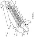
- FIG. 6is a perspective, partially exploded view of an end effector having an adjunct material releasably mounted thereon in accordance with the described techniques
- FIG. 7is a partially exploded side view of the end effector of FIG. 6 ;
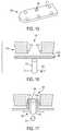
- FIG. 8Ais a cross-sectional view of a portion of the adjunct material and a polymer layer material of FIG. 7 ;
- FIG. 8Bis a cross-sectional view of a portion of the end effector of FIG. 7 having the adjunct material with the polymer layer material releasably retained thereon;
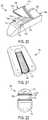
- FIG. 9is a perspective view of an end effector having an adjunct material releasably mounted thereon in accordance with the described techniques
- FIG. 10is a perspective view of an applicator member configured to apply the adjunct material to the end effector of FIG. 9 ;
- FIG. 11is a cross-sectional view of a portion of the end effector of FIG. 9 having the adjunct material releasably retained thereon;
- FIG. 12is a perspective, partially exploded view of an end effector having first and second adjunct materials releasably mounted thereon in accordance with the described techniques;
- FIG. 13is a perspective, partially exploded view of the end effector of FIG. 12 , illustrating the first and second adjunct materials applied to a tissue in a patient;
- FIG. 14is a perspective view of an applicator member configured to apply the first and second adjunct materials to the end effector of FIG. 12 ;
- FIG. 15is a perspective, schematic view of a jaw of an end effector having recesses formed thereon that are configured to mate with portions of an adjunct material in accordance with the described techniques;
- FIG. 16is a perspective, schematic view of the jaw of FIG. 15 and of an applicator member configured to cause the portions of the adjunct material to be received in the recesses in the jaw;
- FIG. 17is a perspective, schematic view of the jaw of FIG. 15 , illustrating the portions of the adjunct material received in the recesses in the jaw using the applicator member;
- FIG. 18is a perspective view of an end effector having an adjunct material releasably mounted thereon in accordance with the described techniques
- FIG. 19is a cross-sectional view of a portion of the end effector of FIG. 18 having the adjunct material releasably retained thereon;
- FIG. 20is a perspective view of an end effector having an adjunct material releasably mounted thereon in accordance with the described techniques
- FIG. 21is a perspective view of an applicator member configured to apply the adjunct material to the end effector of FIG. 20 ;
- FIG. 22is a cross-sectional view of a portion of the end effector of FIG. 20 having the adjunct material releasably retained thereon.
- like-named components of the embodimentsgenerally have similar features, and thus within a particular embodiment each feature of each like-named component is not necessarily fully elaborated upon.
- linear or circular dimensionsare used in the description of the disclosed systems, devices, and methods, such dimensions are not intended to limit the types of shapes that can be used in conjunction with such systems, devices, and methods.
- a person skilled in the artwill recognize that an equivalent to such linear and circular dimensions can easily be determined for any geometric shape. Sizes and shapes of the systems and devices, and the components thereof, can depend at least on the anatomy of the subject in which the systems and devices will be used, the size and shape of components with which the systems and devices will be used, and the methods and procedures in which the systems and devices will be used.
- proximal and distalare used herein with reference to a user, such as a clinician, gripping a handle of an instrument.
- Other spatial termssuch as “front” and “back” similarly correspond respectively to distal and proximal.
- spatial termssuch as “vertical” and “horizontal” are used herein with respect to the drawings. However, surgical instruments are used in many orientations and positions, and these spatial terms are not intended to be limiting and absolute.
- the devices and methods described hereinare provided for open surgical procedures, and in other embodiments, the devices and methods are provided for laparoscopic, endoscopic, and other minimally invasive surgical procedures.
- the devicesmay be fired directly by a human user or remotely under the direct control of a robot or similar manipulation tool.
- a person skilled in the artwill appreciate that the various methods and devices disclosed herein can be used in numerous surgical procedures and applications.
- the various instruments disclosed hereincan be inserted into a body in any way, such as through a natural orifice, through an incision or puncture hole formed in tissue, or through an access device, such as a trocar cannula.
- the working portions or end effector portions of the instrumentscan be inserted directly into a patient's body or can be inserted through an access device that has a working channel through which the end effector and elongated shaft of a surgical instrument can be advanced.
- adjunctscan be used in conjunction with surgical instruments to help improve surgical procedures. While a variety of different surgical end effectors can benefit from the use of adjuncts, in some exemplary embodiments the end effector can be a surgical stapler.
- the adjunct(s)can be disposed between and/or on jaws of the stapler, incorporated into a staple cartridge disposed in the jaws, or otherwise placed in proximity to the staples. When staples are deployed, the adjunct(s) can remain at the treatment site with the staples, in turn providing a number of benefits.
- the adjunct(s)may reinforce tissue at the treatment site, preventing tearing or ripping by the staples at the treatment site. Tissue reinforcement may be needed to keep the staples from tearing through the tissue if the tissue is diseased, is healing from another treatment such as irradiation, medications such as chemotherapy, or other tissue property altering situation. In some instances, the adjunct(s) may minimize tissue movement in and around the staple puncture sites that can occur from tissue deformation that occurs after stapling (e.g., lung inflation, gastrointestinal tract distension, etc.).
- tissue deformatione.g., lung inflation, gastrointestinal tract distension, etc.
- an adjunctcan be useful in distributing pressure applied by the staple thereby reducing the possibility of a staple pulling through a tissue (which can be friable) and failing to fasten the tissue as intended (so-called “cheese wiring”). Additionally, the adjunct can be at least partially stretchable and can thus allow at least partial natural motion of the tissue (e.g., expansion and contraction of lung tissue during breathing).
- a staple linecan be flexible as described, for example, in U.S. Pat. Pub. No. 2016/0089142 entitled “Method for Creating a Flexible Staple Line,” filed on Sep. 26, 2014, which is hereby incorporated by reference herein in its entirety.
- a staple puncture sitemay serve as a stress concentration and that the size of the hole created by the staple will grow when the tissue around it is placed under tension. Restricting the tissues movement around these puncture sites can minimize the size the holes may grow to under tension.
- the adjunct(s)can be configured to wick or absorb beneficial fluids, e.g., sealants, blood, glues, that further promote healing, and in some instances, the adjunct(s) can be configured to degrade to form a gel, e.g., a sealant, that further promotes healing.
- the adjunct(s)can be used to help seal holes formed by staples as they are implanted into tissue, blood vessels, and various other objects or body parts. The adjunct(s) may also affect tissue growth through the spacing, positioning and/or orientation of any fibers or strands associated with the adjunct(s).
- a variety of surgical instrumentscan be used in conjunction with the adjunct(s) and/or medicant(s) disclosed herein. “Adjuncts” are also referred to herein as “adjunct materials.”
- the surgical instrumentscan include surgical staplers.
- a variety of surgical staplerscan be used, for example, linear surgical staplers and circular staplers.
- a linear staplercan be configured to create longitudinal staple lines and can include elongate jaws with a cartridge coupled thereto containing longitudinal staple rows.
- the elongate jawscan include a knife or other cutting element capable of creating a cut between the staple rows along tissue held within the jaws.
- a circular staplercan be configured to create annular staple lines and can include circular jaws with a cartridge containing annular staple rows.
- the circular jawscan include a knife or other cutting element capable of creating a cut inside of the rows of staples to define an opening through tissue held within the jaws.
- the staplerscan be used on a variety of tissues in a variety of different surgical procedures, for example in thoracic surgery or in gastric surgery.
- FIG. 1illustrates one example of a linear surgical stapler 10 suitable for use with one or more adjunct(s) and/or medicant(s).
- the stapler 10generally includes a handle assembly 12 , a shaft 14 extending distally from a distal end 12 d of the handle assembly 12 , and an end effector 30 at a distal end 14 d of the shaft 14 .
- the end effector 30has opposed lower and upper jaws 32 , 34 , although other types of end effectors can be used with the shaft 14 , handle assembly 12 , and components associated with the same.
- the lower jaw 32has a staple channel 56 (see FIG.
- the upper jaw 34has an anvil surface 33 that faces the lower jaw 32 and that is configured to operate as an anvil to help deploy staples of the staple cartridge 40 (the staples are obscured in FIGS. 1 and 2 ).
- At least one of the opposed lower and upper jaws 32 , 34is moveable relative to the other lower and upper jaws 32 , 34 to clamp tissue and/or other objects disposed therebetween.
- one of the opposed lower and upper jaws 32 , 34may be fixed or otherwise immovable.
- both of the opposed lower and upper jaws 32 , 34may be movable.
- Components of a firing systemcan be configured to pass through at least a portion of the end effector 30 to eject the staples into the clamped tissue.
- a knife blade 36(see FIG. 3 ) or other cutting element can be associated with the firing system to cut tissue during the stapling procedure.
- the cutting elementcan be configured to cut tissue at least partially simultaneously with the staples being ejected. In some circumstances, it may be advantageous if the tissue is cut after the staples have been ejected and the tissue is secured. Thus, if a surgical procedure requires that a tissue captured between the jaws be severed, the knife blade 36 is advanced to sever the tissue grasped between the jaws after the staples have been ejected from the staple cartridge 40 .
- Operation of the end effector 30can begin with input from a user, e.g., a clinician, a surgeon, etc., at the handle assembly 12 .
- the handle assembly 12can have many different configurations designed to manipulate and operate the end effector 30 associated therewith.
- the handle assembly 12has a pistol-grip type housing 18 with a variety of mechanical and/or electrical components disposed therein to operate various features of the instrument 10 .
- the handle assembly 12can include a rotation knob 26 mounted adjacent the distal end 12 d thereof which can facilitate rotation of the shaft 14 and/or the end effector 30 with respect to the handle assembly 12 about a longitudinal axis L of the shaft 14 .
- the handle assembly 12can further include clamping components as part of a clamping system actuated by a clamping trigger 22 and firing components as part of the firing system that are actuated by a firing trigger 24 .
- the clamping and firing triggers 22 , 24can be biased to an open position with respect to a stationary handle 20 , for instance by a torsion spring. Movement of the clamping trigger 22 toward the stationary handle 20 can actuate the clamping system, described below, which can cause the jaws 32 , 34 to collapse towards each other and to thereby clamp tissue therebetween.
- Movement of the firing trigger 24can actuate the firing system, described below, which can cause the ejection of staples from the staple cartridge 40 disposed therein and/or the advancement the knife blade 36 to sever tissue captured between the jaws 32 , 34 .
- the firing systemdescribed below, which can cause the ejection of staples from the staple cartridge 40 disposed therein and/or the advancement the knife blade 36 to sever tissue captured between the jaws 32 , 34 .
- a person skilled in the artwill recognize that various configurations of components for a firing system, mechanical, hydraulic, pneumatic, electromechanical, robotic, or otherwise, can be used to eject staples and/or cut tissue.
- the end effector 30 of the illustrated implementationhas the lower jaw 32 that serves as a cartridge assembly or carrier and the opposed upper jaw 34 that serves as an anvil.
- the staple cartridge 40having a plurality of staples therein, is supported in a staple tray 37 , which in turn is supported within a cartridge channel of the lower jaw 32 .
- the upper jaw 34has a plurality of staple forming pockets (not shown), each of which is positioned above a corresponding staple from the plurality of staples contained within the staple cartridge 40 .
- the upper jaw 34can be connected to the lower jaw 32 in a variety of ways, although in the illustrated implementation the upper jaw 34 has a proximal pivoting end 34 p that is pivotally received within a proximal end 56 p of the staple channel 56 , just distal to its engagement to the shaft 14 .
- the upper jaw 34moves the anvil surface 33 and the staple forming pockets formed thereon move toward the opposing staple cartridge 40 .
- a closure tube 46whose distal end includes a horseshoe aperture 46 a that engages the closure feature 34 c , selectively imparts an opening motion to the upper jaw 34 during proximal longitudinal motion and a closing motion to the upper jaw 34 during distal longitudinal motion of the closure tube 46 in response to the clamping trigger 22 .
- the opening and closure of the end effector 30may be effected by relative motion of the lower jaw 32 with respect to the upper jaw 34 , relative motion of the upper jaw 34 with respect to the lower jaw 32 , or by motion of both jaws 32 , 34 with respect to one another.
- the firing components of the illustrated implementationincludes a firing bar 35 , as shown in FIG. 3 , having an E-beam 38 on a distal end thereof.
- the firing bar 35is encompassed within the shaft 14 , for example in a longitudinal firing bar slot 14 s of the shaft 14 , and guided by a firing motion from the handle 12 .
- Actuation of the firing trigger 24can affect distal motion of the E-beam 38 through at least a portion of the end effector 30 to thereby cause the firing of staples contained within the staple cartridge 40 .
- guides 39 projecting from a distal end of the E-Beam 38can engage a wedge sled 47 , shown in FIG. 2 , which in turn can push staple drivers 48 upwardly through staple cavities 41 formed in the staple cartridge 40 .
- Upward movement of the staple drivers 48applies an upward force on each of the plurality of staples within the cartridge 40 to thereby push the staples upwardly against the anvil surface 33 of the upper jaw 34 and create formed staples.
- the E-beam 38can be configured to facilitate closure of the jaws 32 , 34 , spacing of the upper jaw 34 from the staple cartridge 40 , and/or severing of tissue captured between the jaws 32 , 34 .
- a pair of top pins and a pair of bottom pinscan engage one or both of the upper and lower jaws 32 , 34 to compress the jaws 32 , 34 toward one another as the firing bar 35 advances through the end effector 30 .
- the knife 36 extending between the top and bottom pinscan be configured to sever tissue captured between the jaws 32 , 34 .
- the surgical stapler 10can be disposed in a cannula or port and disposed at a surgical site.
- a tissue to be cut and stapledcan be placed between the jaws 32 , 34 of the surgical stapler 10 .
- Features of the stapler 10can be maneuvered as desired by the user to achieve a desired location of the jaws 32 , 34 at the surgical site and the tissue with respect to the jaws 32 , 34 .
- the clamping trigger 22can be pulled toward the stationary handle 20 to actuate the clamping system.
- the clamping trigger 22can cause components of the clamping system to operate such that the closure tube 46 advances distally through at least a portion of the shaft 14 to cause at least one of the jaws 32 , 34 to collapse towards the other to clamp the tissue disposed therebetween. Thereafter, the firing trigger 24 can be pulled toward the stationary handle 20 to cause components of the firing system to operate such that the firing bar 35 and/or the E-beam 38 are advanced distally through at least a portion of the end effector 30 to effect the firing of staples and optionally to sever the tissue captured between the jaws 32 , 34 .
- FIG. 4Another example of a surgical instrument in the form of a linear surgical stapler 50 is illustrated in FIG. 4 .
- the stapler 50can generally be configured and used similar to the stapler 10 of FIG. 1 .
- the surgical instrument 50includes a handle assembly 52 with a shaft 54 extending distally therefrom and having an end effector 60 on a distal end thereof for treating tissue.
- Upper and lower jaws 64 , 62 of the end effector 60can be configured to capture tissue therebetween, staple the tissue by firing of staples from a cartridge 66 disposed in the lower jaw 62 , and/or to create an incision in the tissue.
- an attachment portion 67 on a proximal end of the shaft 54can be configured to allow for removable attachment of the shaft 54 and the end effector 60 to the handle assembly 52 .
- mating features 68 of the attachment portion 67can mate to complementary mating features 71 of the handle assembly 52 .
- the mating features 68 , 71can be configured to couple together via, e.g., a snap fit coupling, a bayonet type coupling, etc., although any number of complementary mating features and any type of coupling can be used to removably couple the shaft 54 to the handle assembly 52 .
- the attachment portion 67can be configured to allow for detachment of only a distal portion of the shaft 54 .
- Detachable coupling of the shaft 54 and/or the end effector 60can allow for selective attachment of a desired end effector 60 for a particular procedure, and/or for reuse of the handle assembly 52 for multiple different procedures.
- the handle assembly 52can have one or more features thereon to manipulate and operate the end effector 60 .
- a rotation knob 72 mounted on a distal end of the handle assembly 52can facilitate rotation of the shaft 54 and/or the end effector 60 with respect to the handle assembly 52 .
- the handle assembly 52can include clamping components as part of a clamping system actuated by a movable trigger 74 and firing components as part of a firing system that can also be actuated by the trigger 74 .
- movement of the trigger 74 toward a stationary handle 70 through a first range of motioncan actuate clamping components to cause the opposed jaws 62 , 64 to approximate toward one another to a closed position.
- only one of the opposed jaws 62 , 24can move to move the jaws 62 , 64 to the closed position. Further movement of the trigger 74 toward the stationary handle 70 through a second range of motion can actuate firing components to cause the ejection of the staples from the staple cartridge 66 and/or the advancement of a knife or other cutting element (not shown) to sever tissue captured between the jaws 62 , 64 .
- FIG. 5One example of a surgical instrument in the form of a circular surgical stapler 80 is illustrated in FIG. 5 .
- the stapler 80can generally be configured and used similar to the linear staplers 10 , 50 of FIGS. 1 and 4 , but with some features accommodating its functionality as a circular stapler.
- the surgical instrument 80includes a handle assembly 82 with a shaft 84 extending distally therefrom and having an end effector 90 on a distal end thereof for treating tissue.
- the end effector 90can include a cartridge assembly 92 and an anvil 94 , each having a tissue-contacting surface that is substantially circular in shape.
- the cartridge assembly 92 and the anvil 94can be coupled together via a shaft 98 extending from the anvil 94 to the handle assembly 82 of the stapler 80 , and manipulating an actuator 85 on the handle assembly 82 can retract and advance the shaft 98 to move the anvil 94 relative to the cartridge assembly 92 .
- the anvil 94 and cartridge assembly 92can perform various functions and can be configured to capture tissue therebetween, staple the tissue by firing of staples from a cartridge 96 of the cartridge assembly 92 and/or can create an incision in the tissue.
- the cartridge assembly 92can house a cartridge containing the staples and can deploy staples against the anvil 94 to form a circular pattern of staples, e.g., staple around a circumference of a tubular body organ.
- the shaft 98can be formed of first and second portions (not shown) configured to releasably couple together to allow the anvil 94 to be detached from the cartridge assembly 92 , which may allow greater flexibility in positioning the anvil 94 and the cartridge assembly 92 in a body of a patient.
- first portion of the shaft 98can be disposed within the cartridge assembly 92 and extend distally outside of the cartridge assembly 92 , terminating in a distal mating feature.
- the second portion of the shaft 98can be disposed within the anvil 94 and extend proximally outside of the cartridge assembly 92 , terminating in a proximal mating feature.
- the proximal and distal mating featurescan be coupled together to allow the anvil 94 and cartridge assembly 92 to move relative to one another.
- the handle assembly 82 of the stapler 80can have various actuators disposed thereon that can control movement of the stapler.
- the handle assembly 82can have a rotation knob 86 disposed thereon to facilitate positioning of the end effector 90 via rotation, and/or the trigger 85 for actuation of the end effector 90 .
- Movement of the trigger 85 toward a stationary handle 87 through a first range of motioncan actuate components of a clamping system to approximate the jaws, i.e. move the anvil 94 toward the cartridge assembly 92 .
- Movement of the trigger 85 toward the stationary handle 87 through a second range of motioncan actuate components of a firing system to cause the staples to deploy from the staple cartridge assembly 92 and/or cause advancement of a knife to sever tissue captured between the cartridge assembly 92 and the anvil 94 .
- surgical stapling instruments 10 , 50 , 80provide only a few examples of many different configurations, and associated methods of use, that can be used in conjunction with the disclosures provided herein. Although the illustrated examples are all configured for use in minimally invasive procedures, it will be appreciated that instruments configured for use in open surgical procedures, e.g., open linear staplers as described in U.S. Pat. No. 8,317,070 entitled “Surgical Stapling Devices That Produce Formed Staples Having Different Lengths” and filed Feb. 28, 2007, can be used in conjunction with the disclosures provided herein. Greater detail on the illustrated examples, as well as additional examples of surgical staplers, components thereof, and their related methods of use, are provided in U.S. Pat. Pub. No.
- 2015/0134077entitled “Sealing Materials For Use In Surgical Stapling” and filed Nov. 8, 2013, entitled “Sealing Materials for Use in Surgical Procedures, and filed on Nov. 8, 2013, U.S. Pat. Pub. No. 2015/0134076, entitled “Hybrid Adjunct Materials for Use in Surgical Stapling,” and filed on Nov. 8, 2013, U.S. Pat. Pub. No. 2015/0133996, entitled “Positively Charged Implantable Materials and Method of Forming the Same,” and filed on Nov. 8, 2013, U.S. Pat. Pub. No. 2015/0129634, entitled “Tissue Ingrowth Materials and Method of Using the Same,” and filed on Nov. 8, 2013, U.S. Pat. Pub. No.
- adjunctsare provided for use in conjunction with surgical stapling instruments.
- the adjunctscan have a variety of configurations, and can be formed from various materials.
- an adjunctcan be formed from one or more of a film, a foam, an injection molded thermoplastic, a vacuum thermoformed material, a fibrous structure, and hybrids thereof.
- the adjunctcan also include one or more biologically-derived materials and one or more drugs. Each of these materials is discussed in more detail below.
- An adjunctcan be formed from a foam, such as a closed-cell foam, an open-cell foam, or a sponge.
- a foamsuch as a closed-cell foam, an open-cell foam, or a sponge.
- An example of how such an adjunct can be fabricatedis from animal derived collagen, such as porcine tendon, that can then be processed and lyophilized into a foam structure. Gelatin can also be used and processed into a foam. Examples of various foam adjuncts are further described in previously mentioned U.S. Pat. No. 8,393,514 entitled “Selectively Orientable Implantable Fastener Cartridge” and filed Sep. 30, 2010.
- An adjunctcan also be formed from a film formed from any suitable material or a combination of materials discussed below.
- the filmcan include one or more layers, each of which can have different degradation rates.
- the filmcan have various regions formed therein, for example, reservoirs that can releasably retain therein one or more medicants in a number of different forms.
- the reservoirs having at least one medicant disposed thereincan be sealed using one or more different coating layers which can include absorbable or non-absorbable polymers.
- the filmcan be formed in various ways. For example, it can be an extruded or a compression molded film.
- the medicantscan also be adsorbed onto the film or bound to the film via non-covalent interactions such as hydrogen bonding.
- An adjunctcan also be formed from injection molded thermoplastic or a vacuum thermoformed material. Examples of various molded adjuncts are further described in U.S. Pat. Pub. No. 2013/0221065 entitled “Fastener Cartridge Comprising A Releasably Attached Tissue Thickness Compensator” and filed Feb. 8, 2013, which is hereby incorporated by reference in its entirety.
- the adjunctcan also be a fiber-based lattice which can be a woven fabric, knitted fabric or non-woven fabric such as a melt-blown, needle-punched or thermal-constructed loose woven fabric.
- An adjunctcan have multiple regions that can be formed from the same type of lattice or from different types of lattices that can together form the adjunct in a number of different ways.
- the fiberscan be woven, braided, knitted, or otherwise interconnected so as to form a regular or irregular structure.
- the fiberscan be interconnected such that the resulting adjunct is relatively loose.
- the adjunctcan include tightly interconnected fibers.
- the adjunctcan be in a form of a sheet, tube, spiral, or any other structure that can include compliant portions and/or more rigid, reinforcement portions.
- the adjunctcan be configured such that certain regions thereof can have more dense fibers while others have less dense fibers.
- the fiber densitycan vary in different directions along one or more dimensions of the adjunct, based on an intended application of the adjunct.
- the adjunctcan be formed from woven, knitted, or otherwise interconnected fibers, which allows the adjunct to be stretched.
- the adjunctcan be configured to stretch in a direction along its longitudinal axis and/or in a lateral direction that is perpendicular to the longitudinal axis. While being stretchable in at least two dimensions (e.g., X and Y directions), the adjunct can provide reinforcement along its thickness (e.g., a Z direction) such that it stretches but resists tearing and pull-through by the staples.
- a Z directione.g., a Z direction
- Non-limiting examples of adjuncts that are configured to be implanted such that they can stretch with the tissueare described in the above-mentioned U.S. Pat. Pub. No. 2016/0089142 entitled “Method for Creating a Flexible Staple Line,” filed on Sep. 26, 2014, which is hereby incorporated by reference herein in its entirety.
- the adjunctcan also be a hybrid construct, such as a laminate composite or melt-locked interconnected fiber.
- a hybrid constructsuch as a laminate composite or melt-locked interconnected fiber. Examples of various hybrid construct adjuncts are further described in U.S. Pat. No. 9,282,962 entitled “Adhesive Film Laminate” and filed Feb. 8, 2013, and in U.S. Pat. No. 7,601,118 entitled “Minimally Invasive Medical Implant And Insertion Device And Method For Using The Same” and filed Sep. 12, 2007, which are hereby incorporated by reference in their entireties.
- the adjuncts in accordance with the described techniquescan be formed from various materials.
- the materialscan be used in various embodiments for different purposes.
- the materialscan be selected in accordance with a desired therapy to be delivered to tissue so as to facilitate tissue in-growth.
- the materialscan include bioabsorbable and biocompatible polymers, including homopolymers and copolymers.
- Bioabsorbable polymerscan be absorbable, resorbable, bioresorbable, or biodegradable polymers.
- An adjunctcan also include active agents, such as active cell culture (e.g., diced autologous tissue, agents used for stem cell therapy (e.g., Biosutures and Cellerix S.L.), hemostatic agents, and tissue healing agents.
- the adjunctscan releasably retain therein at least one medicant that can be selected from a large number of different medicants.
- Medicantsinclude, but are not limited to, drugs or other agents included within, or associated with, the adjuncts that have a desired functionality.
- the medicantsinclude, but are not limited to, for example, antimicrobial agents such as antibacterial and antibiotic agents, antifungal agents, antiviral agents, anti-inflammatory agents, growth factors, analgesics, anesthetics, tissue matrix degeneration inhibitors, anti-cancer agents, hemostatic agents, and other agents that elicit a biological response.
- the adjunctscan also be made from or include agents that enhance visibility during imaging, such as, for example, echogenic materials or radio-opaque materials.
- an adjunct materialis configured to be releasably retained on a jaw of an end effector for a surgical instrument using complementary mating features formed on the jaw and on the adjunct.
- the adjunct materialcan have discrete or longitudinal projections formed thereon at least at distal and proximal ends of the adjunct material. The projections are configured to be received within the complementary recesses formed in a jaw of the end effector to thereby releasably mate the adjunct material with the jaw.
- the end effectorcan include an attachment feature in the form of a polymer attachment layer that can be used to attach the adjunct material to the jaw.
- the end effectorincludes a removable applicator member configured to apply force to the adjunct material to cause the adjunct material to be releasably retained on the jaw.
- the applicator membercan be in the form of an applicator or retainer removably coupled to the end effector, or in the form of a frame-like applicator configured to releasably hold the adjunct material, or in other forms.
- the applicator memberin use, is removably coupled to the end effector and used to apply force to the adjunct material (and in some embodiments to a polymer attachment layer) to cause the projections of the adjunct material (and in some embodiments projections formed on the polymer attachment layer) to be at least partially received within corresponding recesses formed in the jaw.
- a frame-like applicator member holding at least one adjunct materialis clamped between the jaws of the end effector. In this way, force is applied to the applicator member, which causes the applicator member to release the at least one adjunct material and to transfer the at least one adjunct material to at least one respective jaw of the end effector. After use, the applicator member can be separated from the end effector.
- the described techniquescan also employ other ways and structures to releasably retain an adjunct material on at least one jaw of an end effector of a surgical instrument.
- FIGS. 6-8illustrate an example of an end effector 100 configured to releasably retain an adjunct material on one or both of its first and second opposed jaws configured to clamp tissue therebetween, in accordance with the described techniques.
- the end effector 100partially illustrated in FIGS. 6 and 7 , has a first jaw having a cartridge body 102 and a second jaw having an anvil 104 .
- the cartridge body 102is configured to releasably retain thereon an implantable adjunct material 106 .
- the end effector 100can be coupled to a distal end of a shaft of the surgical instrument (not shown).
- the end effector 100can be used in any suitable surgical instrument, for example, a linear surgical stapler (e.g., stapler 10 in FIG. 1 , stapler 50 in FIG. 4 , or any other surgical stapler) which can be suitable for use with at least one adjunct.
- a linear surgical staplere.g., stapler 10 in FIG. 1 , stapler 50 in FIG. 4 , or any
- the cartridge body 102has a plurality of staple-holding cavities 108 configured to seat staples therein, the staple-holding cavities 108 opening on a tissue-facing surface 110 of the cartridge 102 .
- the staple cavities 108form a certain pattern on the surface of the cartridge 102 which corresponds to a pattern of staple-forming cavities (obscured in FIG. 6 ) formed in the anvil 104 .
- the cartridge body 102also referred to as a cartridge, includes a cutting element channel 113 extending between distal and proximal ends 102 d , 102 p of the cartridge 102 .
- the knife channel 113is configured to receive a cutting element (e.g., a knife) as it moves distally therethrough.
- the staple cavities 108can form three rows on both sides of the cutting element channel 113 , though it should be appreciated that the staple cavities 108 can form any other patterns on the tissue-facing surface 110 .
- the cartridge body 102can be in the form of a staple channel configured to support a staple cartridge, which can be removably and replaceably seated within the staple channel. Furthermore, in some embodiments, the cartridge 102 can be part of a disposable loading unit coupled distally to a shaft of a surgical instrument.
- the end effector 100has the implantable adjunct material (or “adjunct”) releasably mounted on one or both of the cartridge 102 and the anvil 104 .
- the adjunct material 106 releasably retained on the cartridge 102is discussed, though it should be appreciated that the anvil 104 can also have an adjunct material releasably retained thereon.
- the end effectoralso includes a loading member 105 configured to apply force to the adjunct material 106 to cause the adjunct material 106 to be retained on the cartridge 102 , as discussed in more detail below.
- the end effector 100can further include a polymer attachment layer 107 configured to be positioned between the cartridge 102 and the adjunct material 106 , as also discussed in more detail below.
- the cartridge 102can have at least one recess formed therein that opens on its tissue-facing surface 110 , with the at least one recess being configured to mate with a respective projection formed in the adjunct 106 .
- the cartridge 102has at least one first recess 112 d formed at the distal end 102 d thereof and at least one second recess 112 p formed at the proximal end 102 p thereof.
- some of the recessesare obscured by the adjunct 106 , and the at least one first recess 112 d is in the form of two recesses formed on opposite sides of the cutting element channel 113 .
- the at least one second recess 112 pis similarly in the form of two recesses formed on opposite sides of the cutting element channel 113 .
- each of the recessesis a discrete recess that has a generally circular top cross-section such that the recess is cylindrical.
- the recesses in the end effector's jaw, such as the cartridgecan have other configurations.
- the recessescan be square, rectangular, semi-circular (e.g., having a semi-circular or oval shape as viewed from the top), and/or they can have any other suitable regular or irregular shapes. Regardless of their specific configuration(s), the recesses formed in the cartridge are configured to receive therein at least a portion of a respective projection formed on an adjunct material or another member, as discussed below.
- the adjunct material 106has projections that are complementary to the recesses 112 d , 112 p formed in the cartridge 102 and that are configured to mate with the recesses 112 d , 112 p to retain the adjunct material 106 on the cartridge 102 .
- the adjunct material's projection(s)are disposed at least at proximal and distal ends of the adjunct material.
- the adjunct material 106has at least one first projection 116 d formed at the distal end 106 d thereof and at least one second projection 116 p formed at the proximal end 106 p thereof.
- the at least one first projection 116 d and the at least one second projection 116 pare each in the form of two respective projections.
- the adjunct material 106can be formed from any suitable material or a combination of materials, which are discussed above.
- the adjunct material 106can have a thickness from about 0.004 inches to about 0.160 inches.
- the adjunct material 106can have a thickness from about 0.006 inches to about 0.008 inches.
- the projections 116 d , 116 pcan have a height or thickness from about 0.005 to about 0.010 inches.
- the projections, which can be formed from an elastomeric materialcan have a height in a range from about 0.005 inches to about 0.015 inches, in a range from about 0.003 inches to about 0.006 inches, or a height that varies in other ranges.
- the projections 116 d , 116 pcan have a height or thickness up to about 0.180 inches or greater.
- the locations of the first projections 116 d and the second projections 116 p formed on the adjunct material 106correspond to the locations of the first recesses 112 d and the second recesses 112 p formed on the cartridge 102 , respectively.
- the first distal projections 116 dcan be closer to one another than the first distal recesses 112 d
- the second proximal projections 116 pcan be closer to one another than the second proximal recesses 112 d
- the configuration and size of the projections 116 d , 116 pcorresponds to those of the recesses 112 d , 112 p . In this way, the projections 116 d , 116 p can be caused to be at least partially received within the recesses 112 d , 112 p , respectively.
- the projections 116 d , 116 p configured to be at least partially received in the recesses 112 d , 112 pare complementary in shape to the recesses such that the projections 116 d , 116 p each have a generally circular top cross-section and are generally cylindrical.
- the projections 116 d , 116 pare formed in the adjunct material 106 such they have an open-end channel extending least partially therethrough that opens on a side 121 of the adjunct material 106 opposed to its side facing the cartridge 102 .
- the projection 116 dwhich can represent all of the projections formed on the adjunct material 106 , is shown to have a channel 119 extending therethrough.
- the channel 119can be formed through the entire projection or through a portion thereof such that a recess can be formed on the side 121 .
- the projections 116 d , 116 p formed in the adjunct material 106may not have a channel extending at least partially therethrough.
- the end effector 100 of the illustrated implementationincludes the polymer attachment layer 107 used in conjunction with the adjunct material 106 .
- the polymer attachment layer 107is disposed between the cartridge 102 and the adjunct material 106 , as shown in FIGS. 6 and 7 .
- the polymer attachment layer 107which can be made from a pressure-sensitive adhesive or other suitable material, is used as an attachment or retaining feature.
- materialscan include materials described in U.S. Pat. Pub. No. 2016/0278774 entitled “Method of Applying a Buttress to a Surgical Stapler,” filed on Mar. 25, 2015, which is hereby incorporated by reference herein in its entirety.
- the polymer attachment layer 107is configured to hold the adjunct material 106 in a releasable engagement with the cartridge 102 . Also, the polymer attachment layer 107 can provide additional reinforcement to a treatment site.
- the polymer material 107can have a size that is the same or approximately the same to that of the adjunct material 106 such the entire surface of the adjunct material 106 is disposed on the polymer material 107 .
- the polymer layermay also serve as a reservoir for medicants such as antimicrobials, chemotherapeutic agents, etc. or be radiopaque for imaging purposes.
- the polymer attachment layer 107includes distal and proximal projections 117 d , 117 p facing the cartridge 102 .
- FIG. 7also illustrates that the distal and proximal projections 117 d , 117 p are formed on the polymer material 107 at locations corresponding to the locations of the adjunct's projections 116 d , 116 p , respectively.
- the distal projections 117 dcan be spaced from the proximal projections 117 p along a longitudinal axis A 1 of the polymer attachment layer 107 by the same distance by which the distal projections 116 d are spaced from the proximal projections 116 p .
- the projections 117 d , 117 pcan be configured similarly to the adjunct's projections 116 d , 116 p —for example, the projections 117 d , 117 p can each optionally have an open-end channel extending least partially therethrough (not shown).
- the distal and proximal projections 117 d , 117 p of the polymer attachment layer 107can have a length or diameter, as measured along the longitudinal axis A 1 , that is similar to that of a length or diameter of the distal and proximal projections 116 d , 116 p of the adjunct material 106 .
- the polymer attachment layer 107can have a thickness from about 0.0005 inches to about 0.001 inches.
- the projections 117 d , 117 pcan have a height or thickness from about 0.005 to about 0.010 inches.
- the projectionswhich can be formed from an elastomeric material, can have a height in a range from about 0.005 inches to about 0.015 inches, in a range from about 0.003 inches to about 0.006 inches, or a height that varies in other ranges.
- the projections 116 d , 116 pcan have a height or thickness up to about 0.180 inches or greater.
- the polymer attachment layer 107can be formed from any suitable material such as, for example, polydioxanone (PDO), PLA/PGA copolymers, or any other suitable polymeric material(s), including pressure sensitive adhesive(s).
- PDOpolydioxanone
- PLA/PGA copolymersPLA/PGA copolymers
- any other suitable polymeric material(s)including pressure sensitive adhesive(s).
- the adjunct material 106can be releasably engaged with the cartridge 102 via the polymer attachment layer 107 .
- the polymer layer's projections 117 d , 117 pcan be formed from the same material as the rest of the polymer attachment layer 107 .
- the distal and proximal projections 117 d , 117 pcan be formed from a different material than the material forming the polymer attachment layer 107 .
- the polymer attachment layer 107can be implanted to a treatment site together with the adjunct 106 . It should be appreciated that, in some embodiments, the polymer attachment layer 107 may not be present.
- the end effector 100can be removably coupled with the loading member 105 having distal and proximal projections 115 d , 115 p and configured to apply force to the adjunct material 106 to thereby cause the adjunct material 106 to mate with the end effector 100 .
- the application of force by the loading member 105 (and thus by the distal and proximal projections 115 d , 115 p thereof) to the adjunct material 106causes the adjunct material's projections 116 d , 116 p to be at least partially received in the recesses 112 d , 112 p of the cartridge 102 .
- the application of force by the loading member 105 to the adjunct material 106 and thus to the polymer attachment layer 107causes the polymer layer's projections 117 d , 117 p to be at least partially received in the recesses 112 d , 112 p of the cartridge 102 .
- the adjunct material's projections 116 d , 116 pcan be caused to be at least partially received within the polymer layer's projections 117 d , 117 p , respectively, as discussed below.
- the distal and proximal projections 115 d , 115 p of the loading member 105can be configured in a number of different ways.
- the distal and proximal projections 115 d , 115 pcan have a length (measured along a longitudinal axis A 2 of the loading member 105 ) that is similar to that of the adjunct material's projections 116 d , 116 p and the polymer layer's projections 117 d , 117 p .
- the distal and proximal projections 115 d , 115 pcan have an open-end channel extending least partially therethrough and opening on a side of the loading member 105 facing the anvil 104 , as shown in FIG. 6 .
- one or more of the projections 115 d , 115 pmay not include such channel.
- the distal and proximal projections 115 d , 115 p of the loading member 105can be spaced apart from one another along the longitudinal axis A 2 by approximately the same distance as the adjunct material's projections 116 d , 116 p and the polymer layer's projections 117 d , 117 p . In some embodiments, however, the distal and proximal projections 115 d , 115 p of the loading member 105 can be configured and/or formed on the loading member 105 in a different way.
- the loading member 105may not include the distal and proximal projections 115 d , 115 p , or the loading member 105 may include only one projection, or other number (e.g., more than two) projections of any suitable configurations.
- the loading member 105can have a variety of different configurations.
- the loading member 105can be in the form of an applicator or retainer that can be removably coupled to the end effector 100 .
- the member 105is an elongate, generally rectangular component having a length and width generally corresponding to the length and width of the tissue-contacting surface of the cartridge 102 .
- the member 105also has a distal tongue portion 120 in the form of a downward bent and a generally flat portion extending distally from the bend. The distal tongue portion 120 can facilitate grip and can serve as a lever.
- the surgeoncan hold the distal tongue portion 120 and apply force thereto in the direction towards the tissue-facing surface 110 of the cartridge 102 to thereby cause the member 105 to apply load to the adjunct material 106 .
- the distal tongue portion 120can be grasped and moved (e.g., moved away from the cartridge body 102 ) to remove the loading member 105 from the end effector 100 .
- the loading member 105can be “preloaded,” or releasably coupled with, the adjunct material 106 and the polymer attachment layer 107 in a suitable manner.
- forceis applied to the adjunct material 106 , either by operating the loading member 105 , or when the loading member 105 is clamped between the cartridge and anvil 102 , 104 , the adjunct material 106 , and the polymer attachment layer 107 (if present) are transferred to the cartridge 102 .
- the loading member 105can then be removed from the end effector 100 .
- the loading member 105can be coupled to the end effector 100 in many different ways.
- the loading member 105is coupled to the proximal end 102 p of the cartridge 102 using one or more suitable features.
- the loading member 105can have at a proximal end 105 p thereof a tab 118 ( FIG. 7 ) configured to engage the proximal end 102 p of the cartridge body 102 .
- any other suitable feature(s)can be used to removably couple the member 105 to the cartridge body 102 .
- the loading member 105may not be coupled to the end effector 100 —e.g., as discussed above it can be clamped between the end effector's jaws to thereby cause the adjunct material 106 (and the polymer attachment layer 107 , if present) to be transferred to the cartridge 102 .
- the adjunct material 106 and the polymer attachment layer 107can be coupled to the loading member 105 in a suitable manner before the adjunct material 106 and the polymer attachment layer 107 are delivered to the cartridge body 102 .
- the loading member 105is configured to evenly apply force to the surface of the adjunct material 106 such that the adjunct material 106 becomes attached to the jaw.
- FIGS. 8A and 8Bdemonstrate such an example where first and second projections 216 a , 216 b of an adjunct material 206 are at least partially received within first and second projections 217 a , 217 b of a polymer layer 207 .
- the adjunct material 206 and the polymer layer 207can be similar, for example, to the adjunct material and polymer layer 106 , 107 ( FIGS. 6 and 7 ), respectively. It should be appreciated that, while FIGS. 6 and 7 illustrate the adjunct material's and polymer layer's distal and proximal projections, FIGS.
- the first and second projections 216 a , 216 b of the adjunct material 206can be similar to the at least one distal projection 116 d of the adjunct material 106 in FIG. 7 .
- the adjunct material 206 and the polymer layer 207can also have respective proximal projections, similar, for example, to the at least one proximal projection 116 p and at least one proximal projection 117 p ( FIG. 7 ), respectively.
- the first and second projections 216 a , 216 b of the adjunct material 206extend from the top into the first and second projections 217 a , 217 b of the polymer layer 207 .
- the adjunct material 206 and the polymer layer 207can be mated in this way in a number of different ways.
- the adjunct material 206can be preloaded with the polymer layer 207 .
- the projections of the adjunct material 206can be mated with the projections of the polymer layer 207 using the loading member or other component(s) configured to apply force to the adjunct material.
- adjunct material 206is mated with the polymer layer 207 so as to result in the structure as shown in FIG. 8A , such adjunct material/polymer layer structure can be caused (e.g., using the loading member 105 or another suitable component) to be engaged with the jaw of an end effector.
- FIG. 8Aillustrates the way in which the adjunct material 206 is mated with the polymer layer 207 so as to result in the structure as shown in FIG. 8A .
- such adjunct material/polymer layer structurecan be caused (e.g., using the loading member 105 or another suitable component) to be engaged with the jaw of an end effector.
- FIG. 8Billustrates that force can be applied (shown by arrow 210 ) to the adjunct material 206 mated with the polymer layer 207 to cause the first and second projections 217 a , 217 b of polymer layer 207 (and thus the first and second projections 216 a , 216 b of the adjunct material 206 mated therewith) to be engaged with corresponding first and second recesses 212 a , 212 b formed in a jaw 202 .
- the jaw 202can be a cartridge body (e.g., cartridge body 102 in FIGS. 6 and 7 ). However, the jaw 202 can also be an anvil, as the described techniques can be used to releasably retain an adjunct material on an anvil of the end effector as well.
- a distance between the first and second recesses 212 a , 212 b formed in the jaw 202can be greater than a distance between the first and second projections 217 a , 217 b of polymer layer 207 (and thus between the first and second projections 216 a , 216 b of the adjunct material 206 ), prior to mating the polymer layer 207 and the adjunct material 206 with the jaw 202 .
- a distance between the first and second projections 217 a , 217 b(and thus between the first and second projections 216 a , 216 b ) can increase, as shown in FIG.
- Projections formed on an adjunct material in accordance with the described embodimentscan have various configurations.
- the projectionscan be longitudinal projections formed on opposed sides of the adjunct material.
- the longitudinal projections formed on the adjunct materialcan be configured to be mated with complementary features (e.g., recesses) formed on a jaw of an end effector.
- FIGS. 9-11illustrate an embodiment of an end effector 300 having a cartridge 302 and an anvil 304 , at least one of which can be configured to be releasably mated with an adjunct material having longitudinal projections.
- the cartridge 302has a plurality of staple cavities 308 configured to seat staples therein, the staple cavities formed on a tissue-facing surface 310 of the cartridge 302 .
- the anvil 304 of the end effector 300shown in FIG. 11 , has a plurality of staple forming cavities (not shown) formed on a tissue-facing surface 314 thereof.
- the end effector 300can have an adjunct material releasably retained on one or both of the jaws 302 , 304 .
- an adjunct material 306can be releasably mated with the cartridge 302 .
- the adjunct material 306has a first longitudinal projection 316 a formed on one side 315 a of the adjunct material 306 and a second longitudinal projection 316 b formed on another, opposite side 315 b of the adjunct material 306 .
- the first and second longitudinal projections 316 a , 316 bextend between distal and proximal ends 306 d , 306 p of the adjunct material 306 .
- the first and second longitudinal projections 316 a , 316 b of the adjunct material 306are configured to mate with respective first and second complementary recesses 312 a , 312 b formed in the tissue-facing surface 310 of the cartridge 302 .
- the first and second longitudinal recesses 312 a , 312 bextend along a longitudinal axis A 3 of the cartridge 302 , are formed on opposed sides of a cutting element channel 313 , and are each adjacent to opposed sides 311 a , 311 b of the tissue-facing surface 310 .
- the longitudinal projections 316 a , 316 b formed on the adjunct material 306can have a number of different configurations.
- the first and second longitudinal projections 316 a , 316 b of the adjunct material 306have mating features 318 a , 318 b formed thereon that are configured to be at received within the corresponding recesses 312 a , 312 b .
- the mating features 318 a , 318 bare in the form of arrows facing towards the recesses 312 a , 312 b formed in the cartridge 302 .
- the longitudinal projections 316 a , 316 bcan be formed from at least partially flexible and/or deformable material such that, as the projections 316 a , 316 b are received within the corresponding recesses 312 a , 312 b , the projections 316 a , 316 b contract to fit into the recesses and, once in the recesses, expand to be fittingly received within the recesses.
- the arrow-shaped mating features 318 a , 318 b extending from the adjunct material's longitudinal projections 316 a , 316 bcan have a width that is greater than that of the respective recesses 312 a , 312 b .
- the mating features 318 a , 318 bWhen the mating features 318 a , 318 b are forced into the recesses 312 a , 312 b , they can first be caused to contract as they are forced into the recesses, where they then expand to be releasably retained therein.
- the arrow-shaped mating features 318 a , 318 bare shown by way of example only, and the mating features formed on the projections can have any suitable configuration.
- the mating featurescan be C-shaped, J-shaped, or they can have any other configuration(s), including different configurations.
- an adjunct material 320 configured to be releasably retained on the anvil 304can have first and second longitudinal projections 322 a , 322 b , which can be similar to the longitudinal projections 316 a , 316 b formed on the adjunct material 306 configured to be releasably retained on the cartridge 302 .
- the anvil 304can have longitudinal recesses formed therein that are configured to receive therein the longitudinal projections 322 a , 322 b.
- One or both of the adjunct materials 306 , 320can be releasably retained on the jaws 302 , 304 , respectively, using an applicator member 305 shown in FIG. 10 .
- the applicator member 305can be in the form of a frame-like holder configured to releasably retain one or both of the adjunct materials 306 , 320 .
- the applicator member 305is in the form of first (e.g., bottom) and second (e.g., top) generally rectangular housings 324 , 326 coupled to one another as shown in FIG. 10 . As also shown in FIG.
- the first and second housing 324 , 326can encompass edges of the long sides of the adjunct materials 306 , 320 disposed within the applicator member 305 .
- the applicator member 305can be in the shape of a generally rectangular frame following an outer perimeter of at least two sides (e.g., long sides) of one or two adjunct materials.
- the applicator member 305encompasses at least in part the portions of the adjunct materials 306 , 320 having first and second longitudinal projections 316 a , 316 b , and 322 a , 322 b , respectively, extending therefrom.
- adjunct materials 306 , 320may be not encompassed by the applicator member 305 , as shown in FIG. 10 .
- the adjunct material 320 to be retained on the anvilis disposed over the adjunct material 306 to be retained on the cartridge. It should be appreciated that the adjunct materials 306 , 320 and the first and second housings 324 , 326 of the applicator member 305 encompassing them can be symmetrical. Thus, either of the adjunct materials 306 , 320 can be applied to the anvil or the cartridge.
- the applicator member 305can be formed from any suitable material (e.g., plastic), and its walls can be relatively thin and it can be disposable.
- the cartridge and anvil 302 , 304can be clamped over the applicator member 305 . In this way, force applied by the jaws 302 , 304 causes the adjunct materials 306 , 320 to separate from the applicator member 305 and to be engaged with the jaws 302 , 304 .
- the longitudinal projections 316 a , 316 b formed in the adjunct material 306mate with the recesses 312 a , 312 b in the cartridge 302
- the longitudinal projections 322 a , 322 b formed in the adjunct material 320mate with the complementary recesses (not shown) in the anvil 304 .
- the cartridge and anvil 302 , 304can be opened and the applicator member 305 can be separated from the end effector 300 .
- the end effector 300 having its cartridge and anvil 302 , 304 thus mated with the adjunct materials 306 , 320 , as shown in FIG. 11can then be used as desired in a surgical procedure.
- the applicator member 305is shown to releasably retain both of the adjunct materials 306 , 320 by way of example only, as the applicator member 305 or a similar component configured to releasably hold at least one adjunct material can be used to transfer an adjunct material only to an end effector's anvil or an end effector's cartridge.
- At least one projection formed on the adjunct materialcan be in the form of a plurality of discrete projections formed from an at least partially flowable or bendable material that has a changeable configuration.
- a suitable applicatorapplies force to the adjunct material to cause each of the discrete projections to be at least partially received within a corresponding recess in a jaw of an end effector
- the configuration of each of the discrete projections that is at least partially received within the corresponding recesschanges to conform to a configuration of the corresponding recess.
- the discrete projectionsare configured to separate from the adjunct material and remain within the recesses in the jaw after the staples are formed against the staple forming cavities to apply the adjunct material to a tissue clamped between the end effector's jaws.
- FIGS. 12-14illustrate anther embodiment of an end effector 400 having a cartridge 402 and an anvil 404 , at least one of which can have an adjunct material releasably retained thereon that is has projections made from an at least partially flowable material.
- the projectionscan also be formed from at least partially bendable, free-flowing, or waxy materials.
- the material from which the projections are formedcan be deformable in various ways. For example, they can be made from polymers/elastomers may deform or bend and still retain memory of their original shape.
- both the cartridge 402 and the anvil 404can have respective adjunct materials 406 , 420 to be releasably retained thereon.
- the adjunct material 406 releasably retained on a tissue-facing surface 410 of the cartridge 402has a plurality of discrete projections 416 configured to be releasably mated with recesses 412 formed in the tissue-facing surface 510 .
- the discrete projections 416are formed along a longitudinal axis A 4 of the adjunct 406 .
- the projections 416 and recesses 412do not need to be evenly spaced and, in some embodiments, they can be disposed at varied distances from one another.
- the locations and number of the projections 416 and recesses 412can be selected based on a desired manner of attaching the adjunct material to the end effector's jaw. Accordingly, the seven evenly spaced projections 416 are shown in FIG. 12 by way of example only, as suitable number of projections can be formed, and the projections can be formed asymmetrically and unevenly spaced with respect to one another.
- the adjunct material 420 releasably retained on a tissue-facing surface 411 of the anvil 402also has a plurality of discrete projections 421 configured to be releasably mated with recesses 434 formed in the tissue-facing surface 411 .
- each of the discrete projections 416 , 421can be formed such that it spans the entirety of, or only a portion of, the width of the respective jaw.
- each of the discrete projections 416 , 421can be in the form of two projections formed on opposed sides of the tissue-facing surface of the jaw, although only one of such projections is shown in FIG. 12 .
- the discrete projections 416 formed on the adjunct material 406 and the discrete projections 421 formed on the adjunct material 420have a generally rectangular shape, as shown in FIG. 12 (where the projections of the anvil's adjunct material 420 are shown partially separated from the anvil 404 ).
- the discrete projections 416 , 421can be formed from an at least partially flowable material and can have a changeable configuration such that, when each of the discrete projections is at least partially received within a corresponding recess in the jaw, the configuration of each discrete projection changes to conform to a configuration of the corresponding recess.
- the at least partially flowable materialcan be any suitable material or a combination of materials.
- the materialscan include a suitable polymeric material, elastomeric material (e.g., silicone), wax, and any other material(s).
- elastomeric materiale.g., silicone
- waxe.g., wax
- any other material(s)e.g., collagen, gelatin hyaluronic acid, sodium alginate, or any other hydrogels.
- a more rigid polymer/elastomercan be used that can be perforated/slitted at the end, such that it frays outward into a T-slot pocket, rather than deforming in bulk, which would require a material with very low shear-resistance.
- a material from which the adjunct is formedcan be used to fill out the recess on its own. This may be possible with non-woven fabrics having fibers that are able to slide/shear relative to each other.
- each of the generally rectangular projections 421 formed on the adjunct material 420 to be releasably retained on the anvil 404“flows” into, or conforms, to the configuration of each of the recesses 434 , as shown in FIG. 12 .
- the projections 416 of the adjunct 406(which can also be generally rectangular projections) “flow” into the T-shaped recesses 412 formed in the cartridge 402 to thus conform to the shape of the recesses 412 .
- the adjunct materials 406 , 420can be transferred to the cartridge and anvil 402 , 404 using an applicator member 405 shown in FIG. 14 , which can be similar to applicator member 305 ( FIG. 10 ).
- the applicator member 405can be a frame-like holder having first and second portions 424 , 426 releasably holding the adjunct materials 406 , 420 .
- the jaws 402 , 404can be clamped upon the applicator member 405 , which causes the adjunct materials 406 , 420 to be mated with the cartridge and anvil 402 , 404 , respectively.
- the projections, on the adjunct materials 406 , 420are received in the recesses 412 , 434 in the cartridge and anvil 402 , 404 so that the projections (which are formed from at least partially flowable material) change their configuration to fill in the recesses and thus adopt the shape of the recesses.
- the applicator member 405can be separated from the end effector 400 .
- a tissue Tis clamped between the cartridge 402 and anvil 404 of the end effector 400 and staples 409 are formed against the staple forming cavities of the anvil 404 .
- the ejection of the staples from the staple-holding cavities opening on the tissue-facing surface 410 of the cartridge 402causes the adjunct materials 406 , 420 to be released from engagement with the cartridge 402 and anvil 404 and to be applied to opposed sides of the tissue T, as also shown in FIG. 13 .
- the discrete projections 416 , 421separate from the adjunct materials 406 , 420 applied to the tissue T and remain within the recesses 412 , 434 , respectively.
- Such embodimentscan be employed in implementations where, for example, the end effector 400 is part of a disposable loading unit configured to be coupled distally to a surgical tool and that is configured to be disposed after use.
- an adjunct material configured to be releasably retained on a jaw of an end effectorcan be formed from at least partially expandable or stretchable material and/or in the form of a film.
- the jawsuch as an anvil or a cartridge, can have one or more recesses formed therein that are configured to receive portions of the adjunct material.
- An applicator membersuch as, e.g., loading member 305 in FIG. 10 , applicator member 405 in FIG. 14 , or a member having any other configuration that has projections formed thereon, can be used to mate the adjunct material with the jaw. For example, when the applicator member is used to apply force to the adjunct material, the projections formed on the applicator member cause portions of the adjunct material to be releasably received within the one or more recesses formed in the jaw.
- FIGS. 15-17illustrate one example of an implementation of an adjunct material 506 configured to be mated with a jaw 500 of an end effector of a surgical instrument.
- the jaw 500is shown generally as a jaw that can be either a cartridge or an anvil. Regardless of its particular configuration, the jaw 500 can have recesses 503 formed in a tissue-facing surface 510 thereof. It should be appreciated that the recesses 503 can be formed at any locations within tissue-facing surface 510 . Also, the six recesses 503 are shown in FIG. 15 for illustrating purposes only, as any suitable number of recesses 503 (e.g., less than six or greater than six) can be formed on the jaw.
- the recesses 503do not need to be evenly spaced and, in some embodiments, they can be disposed at varied distances from one another. The locations and number of the recesses 503 can be selected based on a desired manner of attaching the adjunct material to the end effector's jaw.
- the recesses 503can be formed in the area of the tissue-facing surface 510 occupied by staple-forming cavities (if the jaw 500 is an anvil) or by staple-holding cavities or pockets (if the jaw 500 is a cartridge).
- one or more of the recesses 503can be formed in area(s) of the tissue-facing surface 510 that does not have the staple-forming cavities or the staple-holding pockets.
- one or more recessescan be formed at a distal end of the jaw 500 outside of the area having the staple-forming cavities or the staple-holding pockets, and one or more recesses can be formed at a proximal end of the jaw 500 outside of the area having the staple-forming cavities or the staple-holding pockets.
- one or more of the recesses 503can be the staple-forming cavities or the staple-holding pockets.
- the recesses 503are shown by way of example only as having a generally circular cross-section. However, the recesses 503 can have other suitable shapes, as the described embodiments are not limited in this respect. One or more of the recesses 503 can have features that facilitate their ability to retain a portion of the adjunct material therein. For example, as shown in FIG. 16 , the recess 503 can have retaining features 512 a , 512 b that can be in the form of hooks, teeth, rings, barbs, or retaining elements having any other configuration. It should be appreciated that one or more of the retaining features can be formed, or the recesses 503 can be free of any additional features.
- each recess(e.g., the recess 503 shown in FIG. 16 ) is configured to receive therein a corresponding projection or post 515 formed on an applicator member 505 .
- the applicator member 505having one or more posts (one of which is shown in FIGS. 16 and 17 ), can have any suitable configuration that enables force to be applied by the applicator member 505 to the adjunct material 506 .
- the adjunct material 506can be formed from an at least partially stretchable material.
- the applicator member 505when force is applied by or to the applicator member 505 (as shown by arrow 511 ), the applicator member 505 is brought in proximity to the tissue-facing surface 510 such that the post 515 is at least partially received within the recess 503 .
- the post 515pushes a portion 508 of the adjunct material 506 into the recess 503 , as also shown in FIG. 17 .
- the retaining features 512 a , 512 b extending from the inner walls of the recess 503facilitate retention of the portion 508 of the adjunct material 506 within the recess 503 .
- Other recesses formed in the jaw 500can similarly receive at least partially therein posts formed on the applicator member 505 that thus push portions of the adjunct material 506 into the recesses. In this way, the adjunct material 506 becomes releasably mated with the jaw 500 .
- each of the recesses 503can receive therein a portion of the adjunct material pushed into the recess using a corresponding post. In other implementations, however, only some of the recesses can receive corresponding posts therein.
- the post 515representing just one example of the multiple posts that can extend from the applicator member 505 , is shown as a generally cylindrical element by way of example only, as the post 515 can have other configurations.
- the post 515can be mushroom-shaped (e.g., shaped as a “reversed mushroom”) or it can have a generally rectangular, square, or otherwise shaped cross-section.
- the size of the post 515can be selected such that it fits with clearance within the recess 503 and pushes the portion 508 of the adjunct material 506 into the recess 503 in a manner that allows retaining that portion 508 in the recess 503 , as shown in FIG. 17 .
- the portion 508can be retained in the recess 503 using the retaining features 512 a , 512 b as shown in FIGS. 16 and 17 , or any other type(s) of retaining features.
- adjunct material 506is mated with the jaw 500 using the applicator member 505 , the applicator member 505 is removed, whereas the adjunct material portion 508 remains in the recess 503 .
- the adjunct material 506is separated from the jaw 500 to be transferred to a tissue at a treatment site (e.g., when staples are ejected from the jaw's cartridge), the adjunct material portion 508 is caused to exit the recess 503 .
- the adjunct material 506which can be in the form or a film and/or at least partially stretchable member, can be generally rectangular or it can have other configurations.
- the size of the adjunct material 506can be such that, when its portions (e.g., the portion 508 in FIGS. 16 and 17 ) are mated with the jaw 500 , the adjunct material 506 still covers a desired area of the tissue-facing surface 510 of the jaw 500 .
- the adjunct material 506can be oversized relative to a size of the tissue-facing surface 510 of the jaw 500 . Also, even though some extra material becomes available after the adjunct material's portions are released from the recesses in the jaw, this does not affect the ability of the adjunct material 506 to reinforce and/or treat a site in a patient's body.
- an adjunct materialcan be releasably retained on a jaw of an end effector using a material that can change its configuration when heat is applied thereto.
- FIGS. 18 and 19illustrate an embodiment of an end effector 600 having a cartridge body 602 and an anvil 604 , which can have an adjunct material 606 configured to be retained on at least one of the cartridge body and anvil 602 , 604 using an attachment layer 607 .
- the attachment layer 607can be used to couple the adjunct material 606 to the cartridge body 602 , as discussed in more detail below.
- a tissue-facing surface 610 of the cartridge body 602can have recesses 612 a , 612 b disposed outside of the area of the cartridge body 602 having staple-holding pockets 608 .
- the two recesses 612 a , 612 b formed at a distal end 602 d of the cartridge body 602are shown, and a proximal end 602 p of the cartridge body 602 can have a similar pair of recesses.
- the recesses 612 a , 612 bare disposed at opposed sides of a cutting-element channel 613 in the cartridge body 602 , though the recesses 612 a , 612 b can be disposed at other areas of the tissue-facing surface 610 of the cartridge body 602 .
- the adjunct material 606can have retaining features 616 a , 616 b formed at a distal end 606 d thereof, and similar retaining features 616 c , 616 d formed at a proximal end 606 p thereof.
- the retaining features 616 a , 616 b , 616 c , 616 dare in the form of cupcake-like depressions in the adjunct material 606 extending towards the cartridge body 602 and opening on a side of the adjunct material 606 opposite to its side facing the cartridge body 602 .
- the retaining features 616 a , 616 b , 616 c , 616 dcan have any other shapes, and that the number of the retaining features can be different from four (e.g., less than four or greater than four).
- the retaining features 616 a , 616 b , 616 c , 616 dcan be formed as closed depressions in the adjunct material 606 , or they can be open-ended features opening into the cartridge's recesses when the adjunct is mated therewith.
- the distal retaining features 616 a , 616 bare configured to be received within the distal recesses 612 a , 612 b in the cartridge body 602 .
- the proximal retaining features 616 c , 616 d of the adjunct material 606are configured to be received within the proximal recesses formed in the cartridge body 602 , which are obscured in FIG. 18 .
- the attachment layer 607which can be formed from a suitable heat meltable material, can be used to attach the adjunct material 606 to the cartridge body 602 .
- the adjunct material 606which can have the attachment layer 607 coupled thereto in a suitable manner, can be disposed on the tissue-facing surface 610 of the cartridge body 602 .
- the attachment layer 607can be coupled to the adjunct material 606 or it can be disposed over the adjunct material 606 such that the adjunct material 606 is located between the tissue-facing surface 610 of the cartridge body 602 and the attachment layer 607 .
- the adjunct material 606is disposed over the cartridge body 602 such that the retaining features 616 a , 616 b , 616 c , 616 d are received within the respective recesses formed in the cartridge body 602 .
- the retaining features 616 a , 616 bare received within the recesses 612 a , 612 b.
- a suitable devicecan then be used to apply heat to the attachment layer 607 such that at least some of its portions melt and the attachment layer's material flows into the retaining features 616 a , 616 b , 616 c , 616 d in the adjunct material 606 that, in turn, at least partially seat within respective recesses formed in the cartridge body 602 .
- the material of the attachment layer 607 deposited within each of the retaining features 616 a , 616 b , 616 c , 616 d of the adjunct material 606mates the adjunct material 606 with the cartridge body 602 .
- FIG. 19illustrates by way of example a recess 612 ′ in the cartridge body 602 , which can be representative of any of the recesses (e.g., 612 a , 612 b or others) that can be formed in the cartridge body 602 .
- the recess 612 ′can seat therein a respective retaining feature 616 ′ (e.g., any of the retaining features 616 a , 616 b , 616 c , 616 d ) that in turn, is lined with the material of the attachment layer 607 .
- the attachment layer 607can be formed from any suitable bioabsorbable and/or biodegradable material.
- suitable bioabsorbable and/or biodegradable materialinclude polydioxanone (PDO), lactide/glycolide copolymers, poly-L-lactide, poly-L-lactide-co-D,L-lactide, poly-L-lactide-co-glycolide, poly-4-hydroxybutrate, polycaprolactone, poly lactide-co-glycolide), Poly-L-lactide.
- PDOpolydioxanone
- lactide/glycolide copolymersinclude polydioxanone (PDO), lactide/glycolide copolymers, poly-L-lactide, poly-L-lactide-co-D,L-lactide, poly-L-lactide-co-glycolide, poly-4-hydroxybutrate, polycaprolactone, poly lactide-co-glycoli
- Heat of a suitable temperaturesuch as, for example, between 80° C.° and 120° C.°
- a suitable heater devicee.g., an infrared (IR) heater, ultraviolet (UV) heater, resistive heater, etc.
- IRinfrared
- UVultraviolet
- resistive heaterresistive heater
- the adjunct material 606 and the attachment layer 607can be coupled to the jaw of the end effector 600 , such as the cartridge body 602 , using an applicator member (not shown) configured to apply the adjunct material 606 with the attachment layer 607 to an end effector's jaw.
- the applicator membercan be similar, e.g., to the applicator member 305 ( FIG. 10 ), but can also be equipped with a heating element (e.g., a resistive wire element, UV element, IR element, etc.). Similar to the applicator member 305 , the heat-applying applicator member can releasably hold the adjunct material 606 and the attachment layer 607 .
- the applicator membercan be clamped between the jaws 602 , 604 of the end effector 600 and activated to generate heat to thus melt at least portions of the attachment layer 607 .
- the jaws 602 , 604can be open and the applicator member can be separated from the end effector 600 while leaving the adjunct material 606 and the attachment layer 607 mated with the end effector 600 (in this example, with the cartridge body 602 ).
- an adjunct materialcan be configured to be releasably mated with an anvil in a manner similar to that shown in FIGS. 18 and 19 .
- an adjunct material for use with an end effector of a surgical instrumenthas at least one projection configured to mate with a corresponding at least one recess formed in the end effector.
- an adjunct materialcan be releasably retained on a jaw of an end effector using recesses formed in the adjunct material that are configured to mate with corresponding projections formed on the jaw.
- FIGS. 20-22illustrate an embodiment of an end effector 700 having a cartridge 702 and an anvil 704 , at least one of which can be configured to be releasably mated with an adjunct material having longitudinal channels or recesses.
- the end effector 700has a cartridge 702 and an anvil 704 having any suitable configurations, at least one of which can be configured to be releasably mated with an adjunct material having longitudinal recesses.
- the end effector 700can have adjunct materials releasably retained on both of the jaws 702 , 704 .
- an adjunct material 706can be releasably mated with the cartridge 702 .
- the adjunct material 706has a first longitudinal recess 717 a formed on one side of the adjunct material 706 and a second longitudinal recess 717 b formed on another, opposite side of the adjunct material 706 . As shown, the first and second longitudinal recesses 717 a , 717 extend between distal and proximal ends 706 d , 706 p of the adjunct material 706 .
- the first and second longitudinal recesses 717 a , 717 b of the adjunct material 706are configured to mate with respective first and second complementary projections 715 a , 715 b formed on a tissue-facing surface 710 of the cartridge 702 .
- the projections 715 a , 715 bcan have mating features 718 a , 718 b formed thereon that are configured to mate with the corresponding recesses 717 a , 717 b in the adjunct material 706 .
- the mating features 718 a , 718 bare in the form of arrows facing towards the adjunct material 706 , as shown in FIGS. 20-22 .
- the arrow-shaped mating features 318 a , 318 bare shown by way of example only, and the mating features formed on the projections can have any suitable configuration.
- the mating featurescan be C-shaped, J-shaped, or they can have any other configuration(s), including different configurations.
- the longitudinal recesses 717 a , 717 b formed in the adjunct material 706can have a number of different configurations.
- the first and second longitudinal recesses 717 a , 717 bcan have a shape that is complementary to that of the first and second projections 715 a , 715 b .
- at least a portion of each of the first and second longitudinal recesses 717 a , 717 bcan be arrow-shaped.
- the recesses 717 a , 717 bcan have any other suitable configuration(s).
- the longitudinal projections 715 a , 715 bcan be formed from at least partially flexible and/or deformable material such that, as the projections 715 a , 715 b are received within the corresponding recesses 717 a , 717 b in the adjunct material 706 , the projections 715 a , 715 b are contracted to fit into the recesses and, once in the recesses, are then expanded to be fittingly received within the recesses.
- an adjunct material 720 configured to be releasably retained on the anvil 704can also have first and second longitudinal recesses 723 a , 723 b , which can similar to the longitudinal recesses 717 a , 717 b formed on the adjunct material 706 configured to be releasably retained on the cartridge 702 .
- the anvil 704can have longitudinal projections formed therein that are configured to be received within the longitudinal recesses 723 a , 723 b . Similar to the example shown in FIGS.
- one or both of the adjunct materials 706 , 720can be releasably retained on the jaws 702 , 704 , respectively, using an applicator member 705 shown in FIG. 21 .
- the applicator member 705which can releasably retain therein the adjunct materials 706 , 720 , can be similar to the applicator member 305 ( FIG. 10 ) and is therefore not described in detail herein.
- adjunct materials described hereincan include one or more medicants which can be releasably incorporated into or associated with adjuncts in many different ways. Also, the adjunct materials can have various other features in addition to the features described herein.
- the devices disclosed hereincan be designed to be disposed of after a single use, or they can be designed to be used multiple times. In either case, however, the device can be reconditioned for reuse after at least one use. Reconditioning can include any combination of the steps of disassembly of the device, followed by cleaning or replacement of particular pieces and subsequent reassembly. In particular, the device can be disassembled, and any number of the particular pieces or parts of the device can be selectively replaced or removed in any combination. Upon cleaning and/or replacement of particular parts, the device can be reassembled for subsequent use either at a reconditioning facility, or by a surgical team immediately prior to a surgical procedure.
- reconditioning of a devicecan utilize a variety of techniques for disassembly, cleaning/replacement, and reassembly. Use of such techniques, and the resulting reconditioned device, are all within the scope of the present application.
Landscapes
- Health & Medical Sciences (AREA)
- Life Sciences & Earth Sciences (AREA)
- Surgery (AREA)
- Heart & Thoracic Surgery (AREA)
- Engineering & Computer Science (AREA)
- Biomedical Technology (AREA)
- Nuclear Medicine, Radiotherapy & Molecular Imaging (AREA)
- Medical Informatics (AREA)
- Molecular Biology (AREA)
- Animal Behavior & Ethology (AREA)
- General Health & Medical Sciences (AREA)
- Public Health (AREA)
- Veterinary Medicine (AREA)
- Ophthalmology & Optometry (AREA)
- Surgical Instruments (AREA)
Abstract
Description
Claims (21)
Priority Applications (6)
| Application Number | Priority Date | Filing Date | Title |
|---|---|---|---|
| US15/436,208US10869663B2 (en) | 2017-02-17 | 2017-02-17 | End effector configured to mate with adjunct materials |
| JP2019544637AJP7114614B2 (en) | 2017-02-17 | 2018-02-13 | End effector configured to mate with ancillary material |
| BR112019016996-2ABR112019016996B1 (en) | 2017-02-17 | 2018-02-13 | END ACTUATOR CONFIGURED TO MATCH AUXILIARY MATERIALS |
| PCT/US2018/017923WO2018152079A1 (en) | 2017-02-17 | 2018-02-13 | End effector configured to mate with adjunct materials |
| CN201880025076.6ACN110505847B (en) | 2017-02-17 | 2018-02-13 | End effector configured to engage a dressing material |
| EP18157137.3AEP3363377B1 (en) | 2017-02-17 | 2018-02-16 | End effector configured to mate with adjunct materials |
Applications Claiming Priority (1)
| Application Number | Priority Date | Filing Date | Title |
|---|---|---|---|
| US15/436,208US10869663B2 (en) | 2017-02-17 | 2017-02-17 | End effector configured to mate with adjunct materials |
Publications (2)
| Publication Number | Publication Date |
|---|---|
| US20180235616A1 US20180235616A1 (en) | 2018-08-23 |
| US10869663B2true US10869663B2 (en) | 2020-12-22 |
Family
ID=61231128
Family Applications (1)
| Application Number | Title | Priority Date | Filing Date |
|---|---|---|---|
| US15/436,208Active2038-08-20US10869663B2 (en) | 2017-02-17 | 2017-02-17 | End effector configured to mate with adjunct materials |
Country Status (6)
| Country | Link |
|---|---|
| US (1) | US10869663B2 (en) |
| EP (1) | EP3363377B1 (en) |
| JP (1) | JP7114614B2 (en) |
| CN (1) | CN110505847B (en) |
| BR (1) | BR112019016996B1 (en) |
| WO (1) | WO2018152079A1 (en) |
Cited By (225)
| Publication number | Priority date | Publication date | Assignee | Title |
|---|---|---|---|---|
| US20220361872A1 (en)* | 2021-05-10 | 2022-11-17 | Cilag Gmbh International | Cartridge assemblies with absorbable metal staples and absorbable implantable adjuncts |
| US11529138B2 (en) | 2013-03-01 | 2022-12-20 | Cilag Gmbh International | Powered surgical instrument including a rotary drive screw |
| US11529137B2 (en) | 2019-12-19 | 2022-12-20 | Cilag Gmbh International | Staple cartridge comprising driver retention members |
| US11534162B2 (en) | 2012-06-28 | 2022-12-27 | Cilag GmbH Inlernational | Robotically powered surgical device with manually-actuatable reversing system |
| US11534259B2 (en) | 2020-10-29 | 2022-12-27 | Cilag Gmbh International | Surgical instrument comprising an articulation indicator |
| USD974560S1 (en) | 2020-06-02 | 2023-01-03 | Cilag Gmbh International | Staple cartridge |
| US11547404B2 (en) | 2014-12-18 | 2023-01-10 | Cilag Gmbh International | Surgical instrument assembly comprising a flexible articulation system |
| US11547403B2 (en) | 2014-12-18 | 2023-01-10 | Cilag Gmbh International | Surgical instrument having a laminate firing actuator and lateral buckling supports |
| US11553971B2 (en) | 2019-06-28 | 2023-01-17 | Cilag Gmbh International | Surgical RFID assemblies for display and communication |
| USD975850S1 (en) | 2020-06-02 | 2023-01-17 | Cilag Gmbh International | Staple cartridge |
| US11553916B2 (en) | 2015-09-30 | 2023-01-17 | Cilag Gmbh International | Compressible adjunct with crossing spacer fibers |
| US11553919B2 (en) | 2019-06-28 | 2023-01-17 | Cilag Gmbh International | Method for authenticating the compatibility of a staple cartridge with a surgical instrument |
| USD975851S1 (en) | 2020-06-02 | 2023-01-17 | Cilag Gmbh International | Staple cartridge |
| US11559303B2 (en) | 2016-04-18 | 2023-01-24 | Cilag Gmbh International | Cartridge lockout arrangements for rotary powered surgical cutting and stapling instruments |
| US11559304B2 (en) | 2019-12-19 | 2023-01-24 | Cilag Gmbh International | Surgical instrument comprising a rapid closure mechanism |
| US11559302B2 (en) | 2007-06-04 | 2023-01-24 | Cilag Gmbh International | Surgical instrument including a firing member movable at different speeds |
| USD976401S1 (en) | 2020-06-02 | 2023-01-24 | Cilag Gmbh International | Staple cartridge |
| US11559496B2 (en) | 2010-09-30 | 2023-01-24 | Cilag Gmbh International | Tissue thickness compensator configured to redistribute compressive forces |
| US11564682B2 (en) | 2007-06-04 | 2023-01-31 | Cilag Gmbh International | Surgical stapler device |
| US11564683B2 (en)* | 2020-09-16 | 2023-01-31 | Cilag Gmbh International | Apparatus and method to apply buttress to end effector of surgical stapler via driven member |
| US11564686B2 (en) | 2017-06-28 | 2023-01-31 | Cilag Gmbh International | Surgical shaft assemblies with flexible interfaces |
| US11564688B2 (en) | 2016-12-21 | 2023-01-31 | Cilag Gmbh International | Robotic surgical tool having a retraction mechanism |
| US11571231B2 (en) | 2006-09-29 | 2023-02-07 | Cilag Gmbh International | Staple cartridge having a driver for driving multiple staples |
| US11571215B2 (en) | 2010-09-30 | 2023-02-07 | Cilag Gmbh International | Layer of material for a surgical end effector |
| US11576672B2 (en) | 2019-12-19 | 2023-02-14 | Cilag Gmbh International | Surgical instrument comprising a closure system including a closure member and an opening member driven by a drive screw |
| US11576673B2 (en) | 2005-08-31 | 2023-02-14 | Cilag Gmbh International | Stapling assembly for forming staples to different heights |
| US11576668B2 (en) | 2017-12-21 | 2023-02-14 | Cilag Gmbh International | Staple instrument comprising a firing path display |
| US11583278B2 (en) | 2011-05-27 | 2023-02-21 | Cilag Gmbh International | Surgical stapling system having multi-direction articulation |
| US11583279B2 (en) | 2008-10-10 | 2023-02-21 | Cilag Gmbh International | Powered surgical cutting and stapling apparatus with manually retractable firing system |
| US11596406B2 (en) | 2014-04-16 | 2023-03-07 | Cilag Gmbh International | Fastener cartridges including extensions having different configurations |
| USD980425S1 (en) | 2020-10-29 | 2023-03-07 | Cilag Gmbh International | Surgical instrument assembly |
| US11602340B2 (en) | 2010-09-30 | 2023-03-14 | Cilag Gmbh International | Adhesive film laminate |
| US11612393B2 (en) | 2006-01-31 | 2023-03-28 | Cilag Gmbh International | Robotically-controlled end effector |
| US11612395B2 (en) | 2008-02-14 | 2023-03-28 | Cilag Gmbh International | Surgical system including a control system having an RFID tag reader |
| US11612394B2 (en) | 2011-05-27 | 2023-03-28 | Cilag Gmbh International | Automated end effector component reloading system for use with a robotic system |
| US11617575B2 (en) | 2008-09-23 | 2023-04-04 | Cilag Gmbh International | Motor-driven surgical cutting instrument |
| US11617577B2 (en) | 2020-10-29 | 2023-04-04 | Cilag Gmbh International | Surgical instrument comprising a sensor configured to sense whether an articulation drive of the surgical instrument is actuatable |
| US11622766B2 (en) | 2012-06-28 | 2023-04-11 | Cilag Gmbh International | Empty clip cartridge lockout |
| US11622763B2 (en) | 2013-04-16 | 2023-04-11 | Cilag Gmbh International | Stapling assembly comprising a shiftable drive |
| US11627959B2 (en) | 2019-06-28 | 2023-04-18 | Cilag Gmbh International | Surgical instruments including manual and powered system lockouts |
| US11627960B2 (en) | 2020-12-02 | 2023-04-18 | Cilag Gmbh International | Powered surgical instruments with smart reload with separately attachable exteriorly mounted wiring connections |
| US11638587B2 (en) | 2019-06-28 | 2023-05-02 | Cilag Gmbh International | RFID identification systems for surgical instruments |
| US11642128B2 (en) | 2017-06-28 | 2023-05-09 | Cilag Gmbh International | Method for articulating a surgical instrument |
| US11642125B2 (en) | 2016-04-15 | 2023-05-09 | Cilag Gmbh International | Robotic surgical system including a user interface and a control circuit |
| US11648024B2 (en) | 2006-01-31 | 2023-05-16 | Cilag Gmbh International | Motor-driven surgical cutting and fastening instrument with position feedback |
| US11648008B2 (en) | 2006-01-31 | 2023-05-16 | Cilag Gmbh International | Surgical instrument having force feedback capabilities |
| US11648005B2 (en) | 2008-09-23 | 2023-05-16 | Cilag Gmbh International | Robotically-controlled motorized surgical instrument with an end effector |
| US11653918B2 (en) | 2014-09-05 | 2023-05-23 | Cilag Gmbh International | Local display of tissue parameter stabilization |
| US11653914B2 (en) | 2017-06-20 | 2023-05-23 | Cilag Gmbh International | Systems and methods for controlling motor velocity of a surgical stapling and cutting instrument according to articulation angle of end effector |
| US11653915B2 (en) | 2020-12-02 | 2023-05-23 | Cilag Gmbh International | Surgical instruments with sled location detection and adjustment features |
| US11653920B2 (en) | 2020-12-02 | 2023-05-23 | Cilag Gmbh International | Powered surgical instruments with communication interfaces through sterile barrier |
| US11653917B2 (en) | 2016-12-21 | 2023-05-23 | Cilag Gmbh International | Surgical stapling systems |
| US11660093B2 (en) | 2020-09-16 | 2023-05-30 | Cilag Gmbh International | Method of applying buttress to end effector of surgical stapler |
| US11660163B2 (en) | 2019-06-28 | 2023-05-30 | Cilag Gmbh International | Surgical system with RFID tags for updating motor assembly parameters |
| US11666332B2 (en) | 2007-01-10 | 2023-06-06 | Cilag Gmbh International | Surgical instrument comprising a control circuit configured to adjust the operation of a motor |
| US11672532B2 (en) | 2017-06-20 | 2023-06-13 | Cilag Gmbh International | Techniques for adaptive control of motor velocity of a surgical stapling and cutting instrument |
| US11678877B2 (en) | 2014-12-18 | 2023-06-20 | Cilag Gmbh International | Surgical instrument including a flexible support configured to support a flexible firing member |
| US11678882B2 (en) | 2020-12-02 | 2023-06-20 | Cilag Gmbh International | Surgical instruments with interactive features to remedy incidental sled movements |
| US11678880B2 (en) | 2017-06-28 | 2023-06-20 | Cilag Gmbh International | Surgical instrument comprising a shaft including a housing arrangement |
| US11684365B2 (en) | 2004-07-28 | 2023-06-27 | Cilag Gmbh International | Replaceable staple cartridges for surgical instruments |
| US11684360B2 (en) | 2010-09-30 | 2023-06-27 | Cilag Gmbh International | Staple cartridge comprising a variable thickness compressible portion |
| US11684434B2 (en) | 2019-06-28 | 2023-06-27 | Cilag Gmbh International | Surgical RFID assemblies for instrument operational setting control |
| US11696757B2 (en) | 2021-02-26 | 2023-07-11 | Cilag Gmbh International | Monitoring of internal systems to detect and track cartridge motion status |
| US11696761B2 (en) | 2019-03-25 | 2023-07-11 | Cilag Gmbh International | Firing drive arrangements for surgical systems |
| US11701114B2 (en) | 2014-10-16 | 2023-07-18 | Cilag Gmbh International | Staple cartridge |
| US11701110B2 (en) | 2013-08-23 | 2023-07-18 | Cilag Gmbh International | Surgical instrument including a drive assembly movable in a non-motorized mode of operation |
| US11701111B2 (en) | 2019-12-19 | 2023-07-18 | Cilag Gmbh International | Method for operating a surgical stapling instrument |
| US11701113B2 (en) | 2021-02-26 | 2023-07-18 | Cilag Gmbh International | Stapling instrument comprising a separate power antenna and a data transfer antenna |
| US11701115B2 (en) | 2016-12-21 | 2023-07-18 | Cilag Gmbh International | Methods of stapling tissue |
| US11707273B2 (en) | 2012-06-15 | 2023-07-25 | Cilag Gmbh International | Articulatable surgical instrument comprising a firing drive |
| US11717297B2 (en) | 2014-09-05 | 2023-08-08 | Cilag Gmbh International | Smart cartridge wake up operation and data retention |
| US11717294B2 (en) | 2014-04-16 | 2023-08-08 | Cilag Gmbh International | End effector arrangements comprising indicators |
| US11717285B2 (en) | 2008-02-14 | 2023-08-08 | Cilag Gmbh International | Surgical cutting and fastening instrument having RF electrodes |
| US11717291B2 (en) | 2021-03-22 | 2023-08-08 | Cilag Gmbh International | Staple cartridge comprising staples configured to apply different tissue compression |
| US11717289B2 (en) | 2020-10-29 | 2023-08-08 | Cilag Gmbh International | Surgical instrument comprising an indicator which indicates that an articulation drive is actuatable |
| US11723658B2 (en) | 2021-03-22 | 2023-08-15 | Cilag Gmbh International | Staple cartridge comprising a firing lockout |
| US11723662B2 (en) | 2021-05-28 | 2023-08-15 | Cilag Gmbh International | Stapling instrument comprising an articulation control display |
| US11723657B2 (en) | 2021-02-26 | 2023-08-15 | Cilag Gmbh International | Adjustable communication based on available bandwidth and power capacity |
| US11730473B2 (en) | 2021-02-26 | 2023-08-22 | Cilag Gmbh International | Monitoring of manufacturing life-cycle |
| US11730471B2 (en) | 2016-02-09 | 2023-08-22 | Cilag Gmbh International | Articulatable surgical instruments with single articulation link arrangements |
| US11737751B2 (en) | 2020-12-02 | 2023-08-29 | Cilag Gmbh International | Devices and methods of managing energy dissipated within sterile barriers of surgical instrument housings |
| US11737749B2 (en) | 2021-03-22 | 2023-08-29 | Cilag Gmbh International | Surgical stapling instrument comprising a retraction system |
| US11737754B2 (en) | 2010-09-30 | 2023-08-29 | Cilag Gmbh International | Surgical stapler with floating anvil |
| US11749877B2 (en) | 2021-02-26 | 2023-09-05 | Cilag Gmbh International | Stapling instrument comprising a signal antenna |
| US11744603B2 (en) | 2021-03-24 | 2023-09-05 | Cilag Gmbh International | Multi-axis pivot joints for surgical instruments and methods for manufacturing same |
| US11744583B2 (en) | 2021-02-26 | 2023-09-05 | Cilag Gmbh International | Distal communication array to tune frequency of RF systems |
| US11744588B2 (en) | 2015-02-27 | 2023-09-05 | Cilag Gmbh International | Surgical stapling instrument including a removably attachable battery pack |
| US11744581B2 (en) | 2020-12-02 | 2023-09-05 | Cilag Gmbh International | Powered surgical instruments with multi-phase tissue treatment |
| US11751869B2 (en) | 2021-02-26 | 2023-09-12 | Cilag Gmbh International | Monitoring of multiple sensors over time to detect moving characteristics of tissue |
| US11759208B2 (en) | 2015-12-30 | 2023-09-19 | Cilag Gmbh International | Mechanisms for compensating for battery pack failure in powered surgical instruments |
| US11766258B2 (en) | 2017-06-27 | 2023-09-26 | Cilag Gmbh International | Surgical anvil arrangements |
| US11766261B2 (en) | 2020-09-16 | 2023-09-26 | Cilag Gmbh International | Apparatus and method to apply buttress to end effector of surgical stapler via fixed base |
| US11766259B2 (en) | 2016-12-21 | 2023-09-26 | Cilag Gmbh International | Method of deforming staples from two different types of staple cartridges with the same surgical stapling instrument |
| US11771419B2 (en) | 2019-06-28 | 2023-10-03 | Cilag Gmbh International | Packaging for a replaceable component of a surgical stapling system |
| US11779336B2 (en) | 2016-02-12 | 2023-10-10 | Cilag Gmbh International | Mechanisms for compensating for drivetrain failure in powered surgical instruments |
| US11779420B2 (en) | 2012-06-28 | 2023-10-10 | Cilag Gmbh International | Robotic surgical attachments having manually-actuated retraction assemblies |
| US11779330B2 (en) | 2020-10-29 | 2023-10-10 | Cilag Gmbh International | Surgical instrument comprising a jaw alignment system |
| US11786239B2 (en) | 2021-03-24 | 2023-10-17 | Cilag Gmbh International | Surgical instrument articulation joint arrangements comprising multiple moving linkage features |
| US11786243B2 (en) | 2021-03-24 | 2023-10-17 | Cilag Gmbh International | Firing members having flexible portions for adapting to a load during a surgical firing stroke |
| US11793512B2 (en) | 2005-08-31 | 2023-10-24 | Cilag Gmbh International | Staple cartridges for forming staples having differing formed staple heights |
| US11793518B2 (en) | 2006-01-31 | 2023-10-24 | Cilag Gmbh International | Powered surgical instruments with firing system lockout arrangements |
| US11793513B2 (en) | 2017-06-20 | 2023-10-24 | Cilag Gmbh International | Systems and methods for controlling motor speed according to user input for a surgical instrument |
| US11793516B2 (en) | 2021-03-24 | 2023-10-24 | Cilag Gmbh International | Surgical staple cartridge comprising longitudinal support beam |
| US11793514B2 (en) | 2021-02-26 | 2023-10-24 | Cilag Gmbh International | Staple cartridge comprising sensor array which may be embedded in cartridge body |
| US11793509B2 (en) | 2012-03-28 | 2023-10-24 | Cilag Gmbh International | Staple cartridge including an implantable layer |
| US11793511B2 (en) | 2005-11-09 | 2023-10-24 | Cilag Gmbh International | Surgical instruments |
| US11801051B2 (en) | 2006-01-31 | 2023-10-31 | Cilag Gmbh International | Accessing data stored in a memory of a surgical instrument |
| US11811253B2 (en) | 2016-04-18 | 2023-11-07 | Cilag Gmbh International | Surgical robotic system with fault state detection configurations based on motor current draw |
| US11806013B2 (en) | 2012-06-28 | 2023-11-07 | Cilag Gmbh International | Firing system arrangements for surgical instruments |
| US11806011B2 (en) | 2021-03-22 | 2023-11-07 | Cilag Gmbh International | Stapling instrument comprising tissue compression systems |
| US11812954B2 (en) | 2008-09-23 | 2023-11-14 | Cilag Gmbh International | Robotically-controlled motorized surgical instrument with an end effector |
| US11812958B2 (en) | 2014-12-18 | 2023-11-14 | Cilag Gmbh International | Locking arrangements for detachable shaft assemblies with articulatable surgical end effectors |
| US11812964B2 (en) | 2021-02-26 | 2023-11-14 | Cilag Gmbh International | Staple cartridge comprising a power management circuit |
| US11826048B2 (en) | 2017-06-28 | 2023-11-28 | Cilag Gmbh International | Surgical instrument comprising selectively actuatable rotatable couplers |
| US11826042B2 (en) | 2021-03-22 | 2023-11-28 | Cilag Gmbh International | Surgical instrument comprising a firing drive including a selectable leverage mechanism |
| US11826132B2 (en) | 2015-03-06 | 2023-11-28 | Cilag Gmbh International | Time dependent evaluation of sensor data to determine stability, creep, and viscoelastic elements of measures |
| US11826012B2 (en) | 2021-03-22 | 2023-11-28 | Cilag Gmbh International | Stapling instrument comprising a pulsed motor-driven firing rack |
| US11832816B2 (en) | 2021-03-24 | 2023-12-05 | Cilag Gmbh International | Surgical stapling assembly comprising nonplanar staples and planar staples |
| US11839352B2 (en) | 2007-01-11 | 2023-12-12 | Cilag Gmbh International | Surgical stapling device with an end effector |
| US11839375B2 (en) | 2005-08-31 | 2023-12-12 | Cilag Gmbh International | Fastener cartridge assembly comprising an anvil and different staple heights |
| US11844518B2 (en) | 2020-10-29 | 2023-12-19 | Cilag Gmbh International | Method for operating a surgical instrument |
| US11844520B2 (en) | 2019-12-19 | 2023-12-19 | Cilag Gmbh International | Staple cartridge comprising driver retention members |
| US11849941B2 (en) | 2007-06-29 | 2023-12-26 | Cilag Gmbh International | Staple cartridge having staple cavities extending at a transverse angle relative to a longitudinal cartridge axis |
| US11849946B2 (en) | 2015-09-23 | 2023-12-26 | Cilag Gmbh International | Surgical stapler having downstream current-based motor control |
| US11849945B2 (en) | 2021-03-24 | 2023-12-26 | Cilag Gmbh International | Rotary-driven surgical stapling assembly comprising eccentrically driven firing member |
| US11849944B2 (en) | 2021-03-24 | 2023-12-26 | Cilag Gmbh International | Drivers for fastener cartridge assemblies having rotary drive screws |
| US11849943B2 (en) | 2020-12-02 | 2023-12-26 | Cilag Gmbh International | Surgical instrument with cartridge release mechanisms |
| US11849952B2 (en) | 2010-09-30 | 2023-12-26 | Cilag Gmbh International | Staple cartridge comprising staples positioned within a compressible portion thereof |
| US11857183B2 (en) | 2021-03-24 | 2024-01-02 | Cilag Gmbh International | Stapling assembly components having metal substrates and plastic bodies |
| US11857187B2 (en) | 2010-09-30 | 2024-01-02 | Cilag Gmbh International | Tissue thickness compensator comprising controlled release and expansion |
| US11864760B2 (en) | 2014-10-29 | 2024-01-09 | Cilag Gmbh International | Staple cartridges comprising driver arrangements |
| US11871925B2 (en) | 2020-07-28 | 2024-01-16 | Cilag Gmbh International | Surgical instruments with dual spherical articulation joint arrangements |
| US11871939B2 (en) | 2017-06-20 | 2024-01-16 | Cilag Gmbh International | Method for closed loop control of motor velocity of a surgical stapling and cutting instrument |
| US11871923B2 (en) | 2008-09-23 | 2024-01-16 | Cilag Gmbh International | Motorized surgical instrument |
| US11877748B2 (en) | 2006-10-03 | 2024-01-23 | Cilag Gmbh International | Robotically-driven surgical instrument with E-beam driver |
| US11883020B2 (en) | 2006-01-31 | 2024-01-30 | Cilag Gmbh International | Surgical instrument having a feedback system |
| US11883025B2 (en) | 2010-09-30 | 2024-01-30 | Cilag Gmbh International | Tissue thickness compensator comprising a plurality of layers |
| US11883026B2 (en) | 2014-04-16 | 2024-01-30 | Cilag Gmbh International | Fastener cartridge assemblies and staple retainer cover arrangements |
| USD1013170S1 (en) | 2020-10-29 | 2024-01-30 | Cilag Gmbh International | Surgical instrument assembly |
| US11890012B2 (en) | 2004-07-28 | 2024-02-06 | Cilag Gmbh International | Staple cartridge comprising cartridge body and attached support |
| US11890005B2 (en) | 2017-06-29 | 2024-02-06 | Cilag Gmbh International | Methods for closed loop velocity control for robotic surgical instrument |
| US11890015B2 (en) | 2015-09-30 | 2024-02-06 | Cilag Gmbh International | Compressible adjunct with crossing spacer fibers |
| US11896217B2 (en) | 2020-10-29 | 2024-02-13 | Cilag Gmbh International | Surgical instrument comprising an articulation lock |
| US11896219B2 (en) | 2021-03-24 | 2024-02-13 | Cilag Gmbh International | Mating features between drivers and underside of a cartridge deck |
| US11896222B2 (en) | 2017-12-15 | 2024-02-13 | Cilag Gmbh International | Methods of operating surgical end effectors |
| US11896218B2 (en) | 2021-03-24 | 2024-02-13 | Cilag Gmbh International | Method of using a powered stapling device |
| US11903581B2 (en) | 2019-04-30 | 2024-02-20 | Cilag Gmbh International | Methods for stapling tissue using a surgical instrument |
| US11903582B2 (en) | 2021-03-24 | 2024-02-20 | Cilag Gmbh International | Leveraging surfaces for cartridge installation |
| US11911032B2 (en) | 2019-12-19 | 2024-02-27 | Cilag Gmbh International | Staple cartridge comprising a seating cam |
| US11918212B2 (en) | 2015-03-31 | 2024-03-05 | Cilag Gmbh International | Surgical instrument with selectively disengageable drive systems |
| US11918220B2 (en) | 2012-03-28 | 2024-03-05 | Cilag Gmbh International | Tissue thickness compensator comprising tissue ingrowth features |
| US11918215B2 (en) | 2016-12-21 | 2024-03-05 | Cilag Gmbh International | Staple cartridge with array of staple pockets |
| US11925349B2 (en) | 2021-02-26 | 2024-03-12 | Cilag Gmbh International | Adjustment to transfer parameters to improve available power |
| US11931028B2 (en) | 2016-04-15 | 2024-03-19 | Cilag Gmbh International | Surgical instrument with multiple program responses during a firing motion |
| US11931038B2 (en) | 2014-10-29 | 2024-03-19 | Cilag Gmbh International | Cartridge assemblies for surgical staplers |
| US11931034B2 (en) | 2016-12-21 | 2024-03-19 | Cilag Gmbh International | Surgical stapling instruments with smart staple cartridges |
| US11931025B2 (en) | 2020-10-29 | 2024-03-19 | Cilag Gmbh International | Surgical instrument comprising a releasable closure drive lock |
| USD1018577S1 (en) | 2017-06-28 | 2024-03-19 | Cilag Gmbh International | Display screen or portion thereof with a graphical user interface for a surgical instrument |
| US11937816B2 (en) | 2021-10-28 | 2024-03-26 | Cilag Gmbh International | Electrical lead arrangements for surgical instruments |
| US11944310B2 (en) | 2021-08-13 | 2024-04-02 | Cilag Gmbh International | Non-circular end effector features for surgical stapler |
| US11944336B2 (en) | 2021-03-24 | 2024-04-02 | Cilag Gmbh International | Joint arrangements for multi-planar alignment and support of operational drive shafts in articulatable surgical instruments |
| US11944296B2 (en) | 2020-12-02 | 2024-04-02 | Cilag Gmbh International | Powered surgical instruments with external connectors |
| US11944300B2 (en) | 2017-08-03 | 2024-04-02 | Cilag Gmbh International | Method for operating a surgical system bailout |
| US11944338B2 (en) | 2015-03-06 | 2024-04-02 | Cilag Gmbh International | Multiple level thresholds to modify operation of powered surgical instruments |
| US11950779B2 (en) | 2021-02-26 | 2024-04-09 | Cilag Gmbh International | Method of powering and communicating with a staple cartridge |
| US11950781B2 (en) | 2021-10-29 | 2024-04-09 | Cilag Gmbh International | Discrete adjunct attachment features for surgical stapler |
| US11950777B2 (en) | 2021-02-26 | 2024-04-09 | Cilag Gmbh International | Staple cartridge comprising an information access control system |
| US11957339B2 (en) | 2018-08-20 | 2024-04-16 | Cilag Gmbh International | Method for fabricating surgical stapler anvils |
| US11963680B2 (en) | 2017-10-31 | 2024-04-23 | Cilag Gmbh International | Cartridge body design with force reduction based on firing completion |
| US11974746B2 (en) | 2014-04-16 | 2024-05-07 | Cilag Gmbh International | Anvil for use with a surgical stapling assembly |
| US11974744B2 (en) | 2017-02-17 | 2024-05-07 | Ethicon Llc | Stapling adjunct attachment |
| US11974742B2 (en) | 2017-08-03 | 2024-05-07 | Cilag Gmbh International | Surgical system comprising an articulation bailout |
| US11980363B2 (en) | 2021-10-18 | 2024-05-14 | Cilag Gmbh International | Row-to-row staple array variations |
| US11980362B2 (en) | 2021-02-26 | 2024-05-14 | Cilag Gmbh International | Surgical instrument system comprising a power transfer coil |
| US11980366B2 (en) | 2006-10-03 | 2024-05-14 | Cilag Gmbh International | Surgical instrument |
| US11986183B2 (en) | 2008-02-14 | 2024-05-21 | Cilag Gmbh International | Surgical cutting and fastening instrument comprising a plurality of sensors to measure an electrical parameter |
| US11992213B2 (en) | 2016-12-21 | 2024-05-28 | Cilag Gmbh International | Surgical stapling instruments with replaceable staple cartridges |
| US11992214B2 (en) | 2013-03-14 | 2024-05-28 | Cilag Gmbh International | Control systems for surgical instruments |
| US11998200B2 (en) | 2007-06-22 | 2024-06-04 | Cilag Gmbh International | Surgical stapling instrument with an articulatable end effector |
| US11998206B2 (en) | 2008-02-14 | 2024-06-04 | Cilag Gmbh International | Detachable motor powered surgical instrument |
| US11998194B2 (en) | 2008-02-15 | 2024-06-04 | Cilag Gmbh International | Surgical stapling assembly comprising an adjunct applicator |
| US11998198B2 (en) | 2004-07-28 | 2024-06-04 | Cilag Gmbh International | Surgical stapling instrument incorporating a two-piece E-beam firing mechanism |
| US11998209B2 (en) | 2021-08-13 | 2024-06-04 | Cilag Gmbh International | Staple forming features for circular surgical stapler |
| US11998204B2 (en) | 2021-10-29 | 2024-06-04 | Cilag Gmbh International | Compressible adjunct for surgical stapler |
| US12004740B2 (en) | 2019-06-28 | 2024-06-11 | Cilag Gmbh International | Surgical stapling system having an information decryption protocol |
| US12004745B2 (en) | 2016-12-21 | 2024-06-11 | Cilag Gmbh International | Surgical instrument system comprising an end effector lockout and a firing assembly lockout |
| US12011166B2 (en) | 2016-12-21 | 2024-06-18 | Cilag Gmbh International | Articulatable surgical stapling instruments |
| US12016564B2 (en) | 2014-09-26 | 2024-06-25 | Cilag Gmbh International | Circular fastener cartridges for applying radially expandable fastener lines |
| US12023022B2 (en) | 2014-03-26 | 2024-07-02 | Cilag Gmbh International | Systems and methods for controlling a segmented circuit |
| US12035913B2 (en) | 2019-12-19 | 2024-07-16 | Cilag Gmbh International | Staple cartridge comprising a deployable knife |
| US12053175B2 (en) | 2020-10-29 | 2024-08-06 | Cilag Gmbh International | Surgical instrument comprising a stowed closure actuator stop |
| US12076008B2 (en) | 2018-08-20 | 2024-09-03 | Cilag Gmbh International | Method for operating a powered articulatable surgical instrument |
| US12076017B2 (en) | 2014-09-18 | 2024-09-03 | Cilag Gmbh International | Surgical instrument including a deployable knife |
| US12076011B2 (en) | 2017-10-30 | 2024-09-03 | Cilag Gmbh International | Surgical stapler knife motion controls |
| US12076096B2 (en) | 2017-12-19 | 2024-09-03 | Cilag Gmbh International | Method for determining the position of a rotatable jaw of a surgical instrument attachment assembly |
| US12082806B2 (en) | 2007-01-10 | 2024-09-10 | Cilag Gmbh International | Surgical instrument with wireless communication between control unit and sensor transponders |
| US12089841B2 (en) | 2021-10-28 | 2024-09-17 | Cilag CmbH International | Staple cartridge identification systems |
| US12102323B2 (en) | 2021-03-24 | 2024-10-01 | Cilag Gmbh International | Rotary-driven surgical stapling assembly comprising a floatable component |
| US12108951B2 (en) | 2021-02-26 | 2024-10-08 | Cilag Gmbh International | Staple cartridge comprising a sensing array and a temperature control system |
| US12114859B2 (en) | 2014-12-10 | 2024-10-15 | Cilag Gmbh International | Articulatable surgical instrument system |
| US12137912B2 (en) | 2015-09-30 | 2024-11-12 | Cilag Gmbh International | Compressible adjunct with attachment regions |
| US12156653B2 (en) | 2015-12-30 | 2024-12-03 | Cilag Gmbh International | Surgical instruments with motor control circuits |
| US12161326B2 (en) | 2017-06-27 | 2024-12-10 | Cilag Gmbh International | Surgical anvil manufacturing methods |
| US12171508B2 (en) | 2006-03-23 | 2024-12-24 | Cilag Gmbh International | Robotically-controlled surgical instrument with selectively articulatable end effector |
| US12171507B2 (en) | 2016-08-16 | 2024-12-24 | Cilag Gmbh International | Surgical tool with manual control of end effector jaws |
| US12207835B2 (en) | 2009-12-24 | 2025-01-28 | Cilag Gmbh International | Motor-driven surgical cutting instrument with electric actuator directional control assembly |
| US12213666B2 (en) | 2010-09-30 | 2025-02-04 | Cilag Gmbh International | Tissue thickness compensator comprising layers |
| US12232723B2 (en) | 2014-03-26 | 2025-02-25 | Cilag Gmbh International | Systems and methods for controlling a segmented circuit |
| US12239316B2 (en) | 2011-05-27 | 2025-03-04 | Cilag Gmbh International | Automated end effector component reloading system for use with a robotic system |
| US12245764B2 (en) | 2016-12-21 | 2025-03-11 | Cilag Gmbh International | Shaft assembly comprising a lockout |
| US12245901B2 (en) | 2015-09-25 | 2025-03-11 | Cilag Gmbh International | Implantable layer comprising boundary indicators |
| US12256934B2 (en) | 2021-08-13 | 2025-03-25 | Cilag Gmbh International | Methods of forming an anastomosis between organs with an expandable pattern |
| US12262888B2 (en) | 2018-08-20 | 2025-04-01 | Cilag Gmbh International | Surgical instruments with progressive jaw closure arrangements |
| US12268386B2 (en) | 2021-10-29 | 2025-04-08 | Cilag Gmbh International | Displaceable adjunct attachment features for surgical stapler |
| US12274442B2 (en) | 2016-12-21 | 2025-04-15 | Cilag Gmbh International | Surgical staple cartridge alignment features |
| US12285166B2 (en) | 2014-03-26 | 2025-04-29 | Cilag Gmbh International | Feedback algorithms for manual bailout systems for surgical instruments |
| US12324580B2 (en) | 2021-02-26 | 2025-06-10 | Cilag Gmbh International | Method of powering and communicating with a staple cartridge |
| US12329381B2 (en) | 2019-04-30 | 2025-06-17 | Cilag Gmbh International | Stapling instrument comprising a mounted shaft orientation sensor |
| US12336705B2 (en) | 2017-12-21 | 2025-06-24 | Cilag Gmbh International | Continuous use self-propelled stapling instrument |
| US12383267B2 (en) | 2012-06-28 | 2025-08-12 | Cilag Gmbh International | Robotically powered surgical device with manually-actuatable reversing system |
| US12383259B2 (en) | 2014-09-26 | 2025-08-12 | Cilag Gmbh International | Method for creating a flexible staple line |
| US12414768B2 (en) | 2014-09-05 | 2025-09-16 | Cilag Gmbh International | Staple cartridge electrical contacts |
| US12432790B2 (en) | 2021-10-28 | 2025-09-30 | Cilag Gmbh International | Method and device for transmitting UART communications over a security short range wireless communication |
| US12433627B2 (en) | 2013-03-01 | 2025-10-07 | Cilag Gmbh International | Surgical instrument soft stop |
| US12440208B2 (en) | 2023-08-23 | 2025-10-14 | Cilag Gmbh International | Powered surgical instrument |
Families Citing this family (21)
| Publication number | Priority date | Publication date | Assignee | Title |
|---|---|---|---|---|
| US10588634B2 (en)* | 2017-07-11 | 2020-03-17 | Aesculap Ag | Surgical stapler cartridge loading and unloading |
| USD882782S1 (en) | 2018-02-21 | 2020-04-28 | Ethicon Llc | Three dimensional adjunct |
| US10813637B2 (en)* | 2018-02-21 | 2020-10-27 | Ethicon Llc | Three dimensional adjuncts |
| USD903115S1 (en)* | 2018-12-28 | 2020-11-24 | Ethicon Llc | Applicator for a surgical stapler buttress |
| USD901686S1 (en) | 2018-12-28 | 2020-11-10 | Ethicon Llc | Applicator for surgical stapler buttress |
| EP3965665A1 (en)* | 2019-07-24 | 2022-03-16 | Boston Scientific Scimed, Inc. | Device for fastening tissue |
| US11642130B2 (en) | 2019-09-16 | 2023-05-09 | Cilag Gmbh International | Compressible non-fibrous adjuncts |
| US11490890B2 (en) | 2019-09-16 | 2022-11-08 | Cilag Gmbh International | Compressible non-fibrous adjuncts |
| USD1029255S1 (en) | 2020-09-01 | 2024-05-28 | Cilag Gmbh International | Stapling cartridge assembly with a compressible adjunct |
| US11890010B2 (en)* | 2020-12-02 | 2024-02-06 | Cllag GmbH International | Dual-sided reinforced reload for surgical instruments |
| US11759202B2 (en)* | 2021-03-22 | 2023-09-19 | Cilag Gmbh International | Staple cartridge comprising an implantable layer |
| US11896226B2 (en) | 2021-03-30 | 2024-02-13 | Cilag Gmbh International | Compressible adjuncts with healing-dependent degradation profile |
| US11850332B2 (en) | 2021-03-30 | 2023-12-26 | Cilag Gmbh International | Method for treating tissue |
| US11839374B2 (en) | 2021-03-30 | 2023-12-12 | Cilag Gmbh International | Compressible adjuncts with drug release features |
| US12059153B2 (en) | 2021-03-30 | 2024-08-13 | Cilag Gmbh International | Implantable adjuncts having adjustable degradation profile |
| US11786240B2 (en) | 2021-03-30 | 2023-10-17 | Cilag Gmbh International | Using smart packaging in adjusting use of tissue adjuncts |
| US11864765B2 (en)* | 2021-03-30 | 2024-01-09 | Cilag Gmbh International | Compressible adjuncts with fluid control features |
| US11849950B2 (en) | 2021-03-30 | 2023-12-26 | Cilag Gmbh International | Compressible adjuncts with drug dosage control features |
| US12201301B2 (en)* | 2021-08-13 | 2025-01-21 | Cilag Gmbh International | Circular surgical stapler end effector having staple line alignment feature |
| US11911039B2 (en) | 2021-08-13 | 2024-02-27 | Cilag Gmbh International | Circular surgical stapler having staples with expandable crowns |
| US20230329742A1 (en)* | 2022-04-15 | 2023-10-19 | Cilag Gmbh International | Applicator for surgical instrument lubricant |
Citations (27)
| Publication number | Priority date | Publication date | Assignee | Title |
|---|---|---|---|---|
| US7143925B2 (en) | 2004-07-28 | 2006-12-05 | Ethicon Endo-Surgery, Inc. | Surgical instrument incorporating EAP blocking lockout mechanism |
| US20090001122A1 (en)* | 2007-06-27 | 2009-01-01 | Megan Prommersberger | Buttress and surgical stapling apparatus |
| US7601118B2 (en) | 2004-07-28 | 2009-10-13 | Ethicon, Inc. | Minimally invasive medical implant and insertion device and method for using the same |
| US20120241492A1 (en) | 2010-09-30 | 2012-09-27 | Ethicon Endo-Surgery, Inc. | Tissue thickness compensator comprising at least one medicament |
| US20120241503A1 (en) | 2010-09-30 | 2012-09-27 | Ethicon Endo-Surgery, Inc. | Tissue thickness compensators |
| US20120253298A1 (en)* | 2010-09-30 | 2012-10-04 | Ethicon Endo-Surgery, Inc. | Layered tissue thickness compensator |
| US8317070B2 (en) | 2005-08-31 | 2012-11-27 | Ethicon Endo-Surgery, Inc. | Surgical stapling devices that produce formed staples having different lengths |
| US8393514B2 (en) | 2010-09-30 | 2013-03-12 | Ethicon Endo-Surgery, Inc. | Selectively orientable implantable fastener cartridge |
| US20130161374A1 (en)* | 2008-02-15 | 2013-06-27 | Ethicon Endo-Surgery, Inc. | Layer arrangements for surgical staple cartridges |
| US20130221065A1 (en) | 2010-09-30 | 2013-08-29 | Ethicon Endo-Surgery, Inc. | Fastener cartridge comprising a releasably attached tissue thickness compensator |
| EP2644126A2 (en) | 2012-03-28 | 2013-10-02 | Ethicon Endo-Surgery, Inc. | Devices and methods for attaching tissue thickness compensating materials to surgical stapling instruments |
| US20140224686A1 (en)* | 2013-02-08 | 2014-08-14 | Ethicon Endo-Surgery, Inc. | Staple cartridge comprising a releasable cover |
| US20150122872A1 (en)* | 2009-03-31 | 2015-05-07 | Covidien Lp | Surgical stapling apparatus |
| US20150134076A1 (en) | 2013-11-08 | 2015-05-14 | Ethicon Endo-Surgery, Inc. | Hybrid adjunct materials for use in surgical stapling |
| US20150133995A1 (en) | 2013-11-08 | 2015-05-14 | Ethicon Endo-Surgery, Inc. | Hybrid adjunct materials for use in surgical stapling |
| US20150133996A1 (en) | 2013-11-08 | 2015-05-14 | Ethicon Endo-Surgery, Inc. | Positively charged implantable materials and method of forming the same |
| US20150134077A1 (en) | 2013-11-08 | 2015-05-14 | Ethicon Endo-Surgery, Inc. | Sealing materials for use in surgical stapling |
| US20150129634A1 (en) | 2013-11-08 | 2015-05-14 | Ethicon Endo-Surgery, Inc. | Tissue ingrowth materials and method of using the same |
| US20150277471A1 (en) | 2014-03-26 | 2015-10-01 | Ethicon Endo-Surgery, Inc. | Systems and methods for controlling a segmented circuit |
| US20150272575A1 (en) | 2014-03-26 | 2015-10-01 | Ethicon Endo-Surgery, Inc. | Surgical instrument comprising a sensor system |
| US20150351758A1 (en) | 2014-06-10 | 2015-12-10 | Ethicon Endo-Surgery, Inc. | Adjunct materials and methods of using same in surgical methods for tissue sealing |
| US20160089142A1 (en) | 2014-09-26 | 2016-03-31 | Ethicon Endo-Surgery, Inc. | Method for creating a flexible staple line |
| US20160278764A1 (en)* | 2015-03-25 | 2016-09-29 | Ethicon Endo-Surgery, Llc | Flowable bioabsorbable polymer adhesive for releasably attaching a staple buttress to a surgical stapler |
| US20160278774A1 (en) | 2015-03-25 | 2016-09-29 | Ethicon Endo-Surgery, Llc | Method of applying a buttress to a surgical stapler |
| US20170055986A1 (en) | 2015-08-31 | 2017-03-02 | Ethicon Endo-Surgery, Llc | Medicant Eluting Adjuncts and Methods of Using Medicant Eluting Adjuncts |
| US20170086838A1 (en) | 2015-09-30 | 2017-03-30 | Ethicon Endo-Surgery, Llc | Implantable adjunct comprising bonded layers |
| US10307160B2 (en) | 2015-09-30 | 2019-06-04 | Ethicon Llc | Compressible adjunct assemblies with attachment layers |
Family Cites Families (2)
| Publication number | Priority date | Publication date | Assignee | Title |
|---|---|---|---|---|
| JP4435967B2 (en)* | 2000-12-05 | 2010-03-24 | ジョンソン・エンド・ジョンソン株式会社 | Surgical suture instrument and suture cutting instrument |
| JP2016534794A (en)* | 2013-11-04 | 2016-11-10 | コヴィディエン リミテッド パートナーシップ | Surgical fastener application device |
- 2017
- 2017-02-17USUS15/436,208patent/US10869663B2/enactiveActive
- 2018
- 2018-02-13WOPCT/US2018/017923patent/WO2018152079A1/ennot_activeCeased
- 2018-02-13BRBR112019016996-2Apatent/BR112019016996B1/enactiveIP Right Grant
- 2018-02-13CNCN201880025076.6Apatent/CN110505847B/enactiveActive
- 2018-02-13JPJP2019544637Apatent/JP7114614B2/enactiveActive
- 2018-02-16EPEP18157137.3Apatent/EP3363377B1/enactiveActive
Patent Citations (29)
| Publication number | Priority date | Publication date | Assignee | Title |
|---|---|---|---|---|
| US7601118B2 (en) | 2004-07-28 | 2009-10-13 | Ethicon, Inc. | Minimally invasive medical implant and insertion device and method for using the same |
| US7143925B2 (en) | 2004-07-28 | 2006-12-05 | Ethicon Endo-Surgery, Inc. | Surgical instrument incorporating EAP blocking lockout mechanism |
| US8317070B2 (en) | 2005-08-31 | 2012-11-27 | Ethicon Endo-Surgery, Inc. | Surgical stapling devices that produce formed staples having different lengths |
| US20090001122A1 (en)* | 2007-06-27 | 2009-01-01 | Megan Prommersberger | Buttress and surgical stapling apparatus |
| US20130161374A1 (en)* | 2008-02-15 | 2013-06-27 | Ethicon Endo-Surgery, Inc. | Layer arrangements for surgical staple cartridges |
| US20150122872A1 (en)* | 2009-03-31 | 2015-05-07 | Covidien Lp | Surgical stapling apparatus |
| US20120241492A1 (en) | 2010-09-30 | 2012-09-27 | Ethicon Endo-Surgery, Inc. | Tissue thickness compensator comprising at least one medicament |
| US8393514B2 (en) | 2010-09-30 | 2013-03-12 | Ethicon Endo-Surgery, Inc. | Selectively orientable implantable fastener cartridge |
| US20120253298A1 (en)* | 2010-09-30 | 2012-10-04 | Ethicon Endo-Surgery, Inc. | Layered tissue thickness compensator |
| US20130221065A1 (en) | 2010-09-30 | 2013-08-29 | Ethicon Endo-Surgery, Inc. | Fastener cartridge comprising a releasably attached tissue thickness compensator |
| US20130256377A1 (en) | 2010-09-30 | 2013-10-03 | Ethicon Endo-Surgery, Inc. | Layer comprising deployable attachment members |
| US20120241503A1 (en) | 2010-09-30 | 2012-09-27 | Ethicon Endo-Surgery, Inc. | Tissue thickness compensators |
| US9282962B2 (en) | 2010-09-30 | 2016-03-15 | Ethicon Endo-Surgery, Llc | Adhesive film laminate |
| EP2644126A2 (en) | 2012-03-28 | 2013-10-02 | Ethicon Endo-Surgery, Inc. | Devices and methods for attaching tissue thickness compensating materials to surgical stapling instruments |
| US20140224686A1 (en)* | 2013-02-08 | 2014-08-14 | Ethicon Endo-Surgery, Inc. | Staple cartridge comprising a releasable cover |
| US20150134076A1 (en) | 2013-11-08 | 2015-05-14 | Ethicon Endo-Surgery, Inc. | Hybrid adjunct materials for use in surgical stapling |
| US20150133995A1 (en) | 2013-11-08 | 2015-05-14 | Ethicon Endo-Surgery, Inc. | Hybrid adjunct materials for use in surgical stapling |
| US20150134077A1 (en) | 2013-11-08 | 2015-05-14 | Ethicon Endo-Surgery, Inc. | Sealing materials for use in surgical stapling |
| US20150129634A1 (en) | 2013-11-08 | 2015-05-14 | Ethicon Endo-Surgery, Inc. | Tissue ingrowth materials and method of using the same |
| US20150133996A1 (en) | 2013-11-08 | 2015-05-14 | Ethicon Endo-Surgery, Inc. | Positively charged implantable materials and method of forming the same |
| US20150277471A1 (en) | 2014-03-26 | 2015-10-01 | Ethicon Endo-Surgery, Inc. | Systems and methods for controlling a segmented circuit |
| US20150272575A1 (en) | 2014-03-26 | 2015-10-01 | Ethicon Endo-Surgery, Inc. | Surgical instrument comprising a sensor system |
| US20150351758A1 (en) | 2014-06-10 | 2015-12-10 | Ethicon Endo-Surgery, Inc. | Adjunct materials and methods of using same in surgical methods for tissue sealing |
| US20160089142A1 (en) | 2014-09-26 | 2016-03-31 | Ethicon Endo-Surgery, Inc. | Method for creating a flexible staple line |
| US20160278764A1 (en)* | 2015-03-25 | 2016-09-29 | Ethicon Endo-Surgery, Llc | Flowable bioabsorbable polymer adhesive for releasably attaching a staple buttress to a surgical stapler |
| US20160278774A1 (en) | 2015-03-25 | 2016-09-29 | Ethicon Endo-Surgery, Llc | Method of applying a buttress to a surgical stapler |
| US20170055986A1 (en) | 2015-08-31 | 2017-03-02 | Ethicon Endo-Surgery, Llc | Medicant Eluting Adjuncts and Methods of Using Medicant Eluting Adjuncts |
| US20170086838A1 (en) | 2015-09-30 | 2017-03-30 | Ethicon Endo-Surgery, Llc | Implantable adjunct comprising bonded layers |
| US10307160B2 (en) | 2015-09-30 | 2019-06-04 | Ethicon Llc | Compressible adjunct assemblies with attachment layers |
Non-Patent Citations (1)
| Title |
|---|
| Extended European Search Report fo EP App. No. 18157137.3 dated May 2, 2018 (8 pages). |
Cited By (352)
| Publication number | Priority date | Publication date | Assignee | Title |
|---|---|---|---|---|
| US11963679B2 (en) | 2004-07-28 | 2024-04-23 | Cilag Gmbh International | Articulating surgical stapling instrument incorporating a two-piece E-beam firing mechanism |
| US11890012B2 (en) | 2004-07-28 | 2024-02-06 | Cilag Gmbh International | Staple cartridge comprising cartridge body and attached support |
| US11684365B2 (en) | 2004-07-28 | 2023-06-27 | Cilag Gmbh International | Replaceable staple cartridges for surgical instruments |
| US11998198B2 (en) | 2004-07-28 | 2024-06-04 | Cilag Gmbh International | Surgical stapling instrument incorporating a two-piece E-beam firing mechanism |
| US11882987B2 (en) | 2004-07-28 | 2024-01-30 | Cilag Gmbh International | Articulating surgical stapling instrument incorporating a two-piece E-beam firing mechanism |
| US12011165B2 (en) | 2004-07-28 | 2024-06-18 | Cilag Gmbh International | Surgical stapling instrument comprising replaceable staple cartridge |
| US11896225B2 (en) | 2004-07-28 | 2024-02-13 | Cilag Gmbh International | Staple cartridge comprising a pan |
| US12029423B2 (en) | 2004-07-28 | 2024-07-09 | Cilag Gmbh International | Surgical stapling instrument comprising a staple cartridge |
| US11812960B2 (en) | 2004-07-28 | 2023-11-14 | Cilag Gmbh International | Method of segmenting the operation of a surgical stapling instrument |
| US11771425B2 (en) | 2005-08-31 | 2023-10-03 | Cilag Gmbh International | Stapling assembly for forming staples to different formed heights |
| US11793512B2 (en) | 2005-08-31 | 2023-10-24 | Cilag Gmbh International | Staple cartridges for forming staples having differing formed staple heights |
| US11576673B2 (en) | 2005-08-31 | 2023-02-14 | Cilag Gmbh International | Stapling assembly for forming staples to different heights |
| US11839375B2 (en) | 2005-08-31 | 2023-12-12 | Cilag Gmbh International | Fastener cartridge assembly comprising an anvil and different staple heights |
| US11730474B2 (en) | 2005-08-31 | 2023-08-22 | Cilag Gmbh International | Fastener cartridge assembly comprising a movable cartridge and a staple driver arrangement |
| US11793511B2 (en) | 2005-11-09 | 2023-10-24 | Cilag Gmbh International | Surgical instruments |
| US12161329B2 (en) | 2006-01-31 | 2024-12-10 | Cilag Gmbh International | Surgical systems comprising a control circuit including a timer |
| US11612393B2 (en) | 2006-01-31 | 2023-03-28 | Cilag Gmbh International | Robotically-controlled end effector |
| US11793518B2 (en) | 2006-01-31 | 2023-10-24 | Cilag Gmbh International | Powered surgical instruments with firing system lockout arrangements |
| US11890029B2 (en) | 2006-01-31 | 2024-02-06 | Cilag Gmbh International | Motor-driven surgical cutting and fastening instrument |
| US11883020B2 (en) | 2006-01-31 | 2024-01-30 | Cilag Gmbh International | Surgical instrument having a feedback system |
| US11648008B2 (en) | 2006-01-31 | 2023-05-16 | Cilag Gmbh International | Surgical instrument having force feedback capabilities |
| US11648024B2 (en) | 2006-01-31 | 2023-05-16 | Cilag Gmbh International | Motor-driven surgical cutting and fastening instrument with position feedback |
| US11944299B2 (en) | 2006-01-31 | 2024-04-02 | Cilag Gmbh International | Surgical instrument having force feedback capabilities |
| US11660110B2 (en) | 2006-01-31 | 2023-05-30 | Cilag Gmbh International | Motor-driven surgical cutting and fastening instrument with tactile position feedback |
| US11801051B2 (en) | 2006-01-31 | 2023-10-31 | Cilag Gmbh International | Accessing data stored in a memory of a surgical instrument |
| US11890008B2 (en) | 2006-01-31 | 2024-02-06 | Cilag Gmbh International | Surgical instrument with firing lockout |
| US12433584B2 (en) | 2006-01-31 | 2025-10-07 | Cilag Gmbh International | Robotically-controlled end effector |
| US12171508B2 (en) | 2006-03-23 | 2024-12-24 | Cilag Gmbh International | Robotically-controlled surgical instrument with selectively articulatable end effector |
| US11571231B2 (en) | 2006-09-29 | 2023-02-07 | Cilag Gmbh International | Staple cartridge having a driver for driving multiple staples |
| US11622785B2 (en) | 2006-09-29 | 2023-04-11 | Cilag Gmbh International | Surgical staples having attached drivers and stapling instruments for deploying the same |
| US11877748B2 (en) | 2006-10-03 | 2024-01-23 | Cilag Gmbh International | Robotically-driven surgical instrument with E-beam driver |
| US12178434B2 (en) | 2006-10-03 | 2024-12-31 | Cilag Gmbh International | Surgical stapling system including control circuit to monitor clamping pressure |
| US11980366B2 (en) | 2006-10-03 | 2024-05-14 | Cilag Gmbh International | Surgical instrument |
| US11931032B2 (en) | 2007-01-10 | 2024-03-19 | Cilag Gmbh International | Surgical instrument with wireless communication between a control unit of a robotic system and remote sensor |
| US12082806B2 (en) | 2007-01-10 | 2024-09-10 | Cilag Gmbh International | Surgical instrument with wireless communication between control unit and sensor transponders |
| US11849947B2 (en) | 2007-01-10 | 2023-12-26 | Cilag Gmbh International | Surgical system including a control circuit and a passively-powered transponder |
| US11771426B2 (en) | 2007-01-10 | 2023-10-03 | Cilag Gmbh International | Surgical instrument with wireless communication |
| US11666332B2 (en) | 2007-01-10 | 2023-06-06 | Cilag Gmbh International | Surgical instrument comprising a control circuit configured to adjust the operation of a motor |
| US11918211B2 (en) | 2007-01-10 | 2024-03-05 | Cilag Gmbh International | Surgical stapling instrument for use with a robotic system |
| US11844521B2 (en) | 2007-01-10 | 2023-12-19 | Cilag Gmbh International | Surgical instrument for use with a robotic system |
| US12004743B2 (en) | 2007-01-10 | 2024-06-11 | Cilag Gmbh International | Staple cartridge comprising a sloped wall |
| US11812961B2 (en) | 2007-01-10 | 2023-11-14 | Cilag Gmbh International | Surgical instrument including a motor control system |
| US11937814B2 (en) | 2007-01-10 | 2024-03-26 | Cilag Gmbh International | Surgical instrument for use with a robotic system |
| US11839352B2 (en) | 2007-01-11 | 2023-12-12 | Cilag Gmbh International | Surgical stapling device with an end effector |
| US11648006B2 (en) | 2007-06-04 | 2023-05-16 | Cilag Gmbh International | Robotically-controlled shaft based rotary drive systems for surgical instruments |
| US12035906B2 (en) | 2007-06-04 | 2024-07-16 | Cilag Gmbh International | Surgical instrument including a handle system for advancing a cutting member |
| US11559302B2 (en) | 2007-06-04 | 2023-01-24 | Cilag Gmbh International | Surgical instrument including a firing member movable at different speeds |
| US11992208B2 (en) | 2007-06-04 | 2024-05-28 | Cilag Gmbh International | Rotary drive systems for surgical instruments |
| US11911028B2 (en) | 2007-06-04 | 2024-02-27 | Cilag Gmbh International | Surgical instruments for use with a robotic surgical system |
| US12023024B2 (en) | 2007-06-04 | 2024-07-02 | Cilag Gmbh International | Robotically-controlled shaft based rotary drive systems for surgical instruments |
| US11564682B2 (en) | 2007-06-04 | 2023-01-31 | Cilag Gmbh International | Surgical stapler device |
| US11672531B2 (en) | 2007-06-04 | 2023-06-13 | Cilag Gmbh International | Rotary drive systems for surgical instruments |
| US11857181B2 (en) | 2007-06-04 | 2024-01-02 | Cilag Gmbh International | Robotically-controlled shaft based rotary drive systems for surgical instruments |
| US11998200B2 (en) | 2007-06-22 | 2024-06-04 | Cilag Gmbh International | Surgical stapling instrument with an articulatable end effector |
| US11925346B2 (en) | 2007-06-29 | 2024-03-12 | Cilag Gmbh International | Surgical staple cartridge including tissue supporting surfaces |
| US12023025B2 (en) | 2007-06-29 | 2024-07-02 | Cilag Gmbh International | Surgical stapling instrument having a releasable buttress material |
| US11849941B2 (en) | 2007-06-29 | 2023-12-26 | Cilag Gmbh International | Staple cartridge having staple cavities extending at a transverse angle relative to a longitudinal cartridge axis |
| US11801047B2 (en) | 2008-02-14 | 2023-10-31 | Cilag Gmbh International | Surgical stapling system comprising a control circuit configured to selectively monitor tissue impedance and adjust control of a motor |
| US11986183B2 (en) | 2008-02-14 | 2024-05-21 | Cilag Gmbh International | Surgical cutting and fastening instrument comprising a plurality of sensors to measure an electrical parameter |
| US11998206B2 (en) | 2008-02-14 | 2024-06-04 | Cilag Gmbh International | Detachable motor powered surgical instrument |
| US11612395B2 (en) | 2008-02-14 | 2023-03-28 | Cilag Gmbh International | Surgical system including a control system having an RFID tag reader |
| US11717285B2 (en) | 2008-02-14 | 2023-08-08 | Cilag Gmbh International | Surgical cutting and fastening instrument having RF electrodes |
| US12213671B2 (en) | 2008-02-14 | 2025-02-04 | Cilag Gmbh International | Motorized system having a plurality of power sources |
| US11998194B2 (en) | 2008-02-15 | 2024-06-04 | Cilag Gmbh International | Surgical stapling assembly comprising an adjunct applicator |
| US11617576B2 (en) | 2008-09-23 | 2023-04-04 | Cilag Gmbh International | Motor-driven surgical cutting instrument |
| US11812954B2 (en) | 2008-09-23 | 2023-11-14 | Cilag Gmbh International | Robotically-controlled motorized surgical instrument with an end effector |
| US12029415B2 (en) | 2008-09-23 | 2024-07-09 | Cilag Gmbh International | Motor-driven surgical cutting instrument |
| US11648005B2 (en) | 2008-09-23 | 2023-05-16 | Cilag Gmbh International | Robotically-controlled motorized surgical instrument with an end effector |
| US11871923B2 (en) | 2008-09-23 | 2024-01-16 | Cilag Gmbh International | Motorized surgical instrument |
| US11684361B2 (en) | 2008-09-23 | 2023-06-27 | Cilag Gmbh International | Motor-driven surgical cutting instrument |
| US11617575B2 (en) | 2008-09-23 | 2023-04-04 | Cilag Gmbh International | Motor-driven surgical cutting instrument |
| US11793521B2 (en) | 2008-10-10 | 2023-10-24 | Cilag Gmbh International | Powered surgical cutting and stapling apparatus with manually retractable firing system |
| US11730477B2 (en) | 2008-10-10 | 2023-08-22 | Cilag Gmbh International | Powered surgical system with manually retractable firing system |
| US11583279B2 (en) | 2008-10-10 | 2023-02-21 | Cilag Gmbh International | Powered surgical cutting and stapling apparatus with manually retractable firing system |
| US12207835B2 (en) | 2009-12-24 | 2025-01-28 | Cilag Gmbh International | Motor-driven surgical cutting instrument with electric actuator directional control assembly |
| US11602340B2 (en) | 2010-09-30 | 2023-03-14 | Cilag Gmbh International | Adhesive film laminate |
| US11684360B2 (en) | 2010-09-30 | 2023-06-27 | Cilag Gmbh International | Staple cartridge comprising a variable thickness compressible portion |
| US11812965B2 (en) | 2010-09-30 | 2023-11-14 | Cilag Gmbh International | Layer of material for a surgical end effector |
| US11850310B2 (en) | 2010-09-30 | 2023-12-26 | Cilag Gmbh International | Staple cartridge including an adjunct |
| US11672536B2 (en) | 2010-09-30 | 2023-06-13 | Cilag Gmbh International | Layer of material for a surgical end effector |
| US11849952B2 (en) | 2010-09-30 | 2023-12-26 | Cilag Gmbh International | Staple cartridge comprising staples positioned within a compressible portion thereof |
| US11911027B2 (en) | 2010-09-30 | 2024-02-27 | Cilag Gmbh International | Adhesive film laminate |
| US11737754B2 (en) | 2010-09-30 | 2023-08-29 | Cilag Gmbh International | Surgical stapler with floating anvil |
| US11925354B2 (en) | 2010-09-30 | 2024-03-12 | Cilag Gmbh International | Staple cartridge comprising staples positioned within a compressible portion thereof |
| US11883025B2 (en) | 2010-09-30 | 2024-01-30 | Cilag Gmbh International | Tissue thickness compensator comprising a plurality of layers |
| US11857187B2 (en) | 2010-09-30 | 2024-01-02 | Cilag Gmbh International | Tissue thickness compensator comprising controlled release and expansion |
| US11583277B2 (en) | 2010-09-30 | 2023-02-21 | Cilag Gmbh International | Layer of material for a surgical end effector |
| US11957795B2 (en) | 2010-09-30 | 2024-04-16 | Cilag Gmbh International | Tissue thickness compensator configured to redistribute compressive forces |
| US12178432B2 (en) | 2010-09-30 | 2024-12-31 | Cilag Gmbh International | Tissue thickness compensator comprising laterally offset layers |
| US11571215B2 (en) | 2010-09-30 | 2023-02-07 | Cilag Gmbh International | Layer of material for a surgical end effector |
| US12213666B2 (en) | 2010-09-30 | 2025-02-04 | Cilag Gmbh International | Tissue thickness compensator comprising layers |
| US11559496B2 (en) | 2010-09-30 | 2023-01-24 | Cilag Gmbh International | Tissue thickness compensator configured to redistribute compressive forces |
| US11944292B2 (en) | 2010-09-30 | 2024-04-02 | Cilag Gmbh International | Anvil layer attached to a proximal end of an end effector |
| US12059154B2 (en) | 2011-05-27 | 2024-08-13 | Cilag Gmbh International | Surgical instrument with detachable motor control unit |
| US12239316B2 (en) | 2011-05-27 | 2025-03-04 | Cilag Gmbh International | Automated end effector component reloading system for use with a robotic system |
| US12256930B2 (en) | 2011-05-27 | 2025-03-25 | Cilag Gmbh International | Robotically-driven surgical instrument with E-beam driver |
| US11583278B2 (en) | 2011-05-27 | 2023-02-21 | Cilag Gmbh International | Surgical stapling system having multi-direction articulation |
| US11612394B2 (en) | 2011-05-27 | 2023-03-28 | Cilag Gmbh International | Automated end effector component reloading system for use with a robotic system |
| US12290261B2 (en) | 2011-05-27 | 2025-05-06 | Cilag Gmbh International | Robotically-driven surgical instrument with E-beam driver |
| US11974747B2 (en) | 2011-05-27 | 2024-05-07 | Cilag Gmbh International | Surgical stapling instruments with rotatable staple deployment arrangements |
| US11918208B2 (en) | 2011-05-27 | 2024-03-05 | Cilag Gmbh International | Robotically-controlled shaft based rotary drive systems for surgical instruments |
| US11918220B2 (en) | 2012-03-28 | 2024-03-05 | Cilag Gmbh International | Tissue thickness compensator comprising tissue ingrowth features |
| US12121234B2 (en) | 2012-03-28 | 2024-10-22 | Cilag Gmbh International | Staple cartridge assembly comprising a compensator |
| US11793509B2 (en) | 2012-03-28 | 2023-10-24 | Cilag Gmbh International | Staple cartridge including an implantable layer |
| US11707273B2 (en) | 2012-06-15 | 2023-07-25 | Cilag Gmbh International | Articulatable surgical instrument comprising a firing drive |
| US11857189B2 (en) | 2012-06-28 | 2024-01-02 | Cilag Gmbh International | Surgical instrument including first and second articulation joints |
| US11622766B2 (en) | 2012-06-28 | 2023-04-11 | Cilag Gmbh International | Empty clip cartridge lockout |
| US11806013B2 (en) | 2012-06-28 | 2023-11-07 | Cilag Gmbh International | Firing system arrangements for surgical instruments |
| US11918213B2 (en) | 2012-06-28 | 2024-03-05 | Cilag Gmbh International | Surgical stapler including couplers for attaching a shaft to an end effector |
| US11534162B2 (en) | 2012-06-28 | 2022-12-27 | Cilag GmbH Inlernational | Robotically powered surgical device with manually-actuatable reversing system |
| US12383267B2 (en) | 2012-06-28 | 2025-08-12 | Cilag Gmbh International | Robotically powered surgical device with manually-actuatable reversing system |
| US11540829B2 (en) | 2012-06-28 | 2023-01-03 | Cilag Gmbh International | Surgical instrument system including replaceable end effectors |
| US11779420B2 (en) | 2012-06-28 | 2023-10-10 | Cilag Gmbh International | Robotic surgical attachments having manually-actuated retraction assemblies |
| US12369911B2 (en) | 2012-06-28 | 2025-07-29 | Cilag Gmbh International | Firing system lockout arrangements for surgical instruments |
| US12343013B2 (en) | 2012-06-28 | 2025-07-01 | Cilag Gmbh International | Interconnected joint segments forming drive tube for stapling assembly |
| US12433627B2 (en) | 2013-03-01 | 2025-10-07 | Cilag Gmbh International | Surgical instrument soft stop |
| US11529138B2 (en) | 2013-03-01 | 2022-12-20 | Cilag Gmbh International | Powered surgical instrument including a rotary drive screw |
| US11957345B2 (en) | 2013-03-01 | 2024-04-16 | Cilag Gmbh International | Articulatable surgical instruments with conductive pathways for signal communication |
| US11992214B2 (en) | 2013-03-14 | 2024-05-28 | Cilag Gmbh International | Control systems for surgical instruments |
| US11622763B2 (en) | 2013-04-16 | 2023-04-11 | Cilag Gmbh International | Stapling assembly comprising a shiftable drive |
| US12161320B2 (en) | 2013-04-16 | 2024-12-10 | Cilag Gmbh International | Powered surgical stapler |
| US11638581B2 (en) | 2013-04-16 | 2023-05-02 | Cilag Gmbh International | Powered surgical stapler |
| US11690615B2 (en) | 2013-04-16 | 2023-07-04 | Cilag Gmbh International | Surgical system including an electric motor and a surgical instrument |
| US12178429B2 (en) | 2013-04-16 | 2024-12-31 | Cilag Gmbh International | Surgical instruments having modular end effector selectively coupleable to housing assembly |
| US11633183B2 (en) | 2013-04-16 | 2023-04-25 | Cilag International GmbH | Stapling assembly comprising a retraction drive |
| US11701110B2 (en) | 2013-08-23 | 2023-07-18 | Cilag Gmbh International | Surgical instrument including a drive assembly movable in a non-motorized mode of operation |
| US11918209B2 (en) | 2013-08-23 | 2024-03-05 | Cilag Gmbh International | Torque optimization for surgical instruments |
| US12053176B2 (en) | 2013-08-23 | 2024-08-06 | Cilag Gmbh International | End effector detention systems for surgical instruments |
| US12232723B2 (en) | 2014-03-26 | 2025-02-25 | Cilag Gmbh International | Systems and methods for controlling a segmented circuit |
| US12285166B2 (en) | 2014-03-26 | 2025-04-29 | Cilag Gmbh International | Feedback algorithms for manual bailout systems for surgical instruments |
| US12023022B2 (en) | 2014-03-26 | 2024-07-02 | Cilag Gmbh International | Systems and methods for controlling a segmented circuit |
| US12324585B2 (en) | 2014-04-16 | 2025-06-10 | Cilag Gmbh International | Fastener cartridges including extensions having different configurations |
| US11944307B2 (en) | 2014-04-16 | 2024-04-02 | Cilag Gmbh International | Surgical stapling system including jaw windows |
| US12285171B2 (en) | 2014-04-16 | 2025-04-29 | Cilag Gmbh International | Fastener cartridges including extensions having different configurations |
| US11974746B2 (en) | 2014-04-16 | 2024-05-07 | Cilag Gmbh International | Anvil for use with a surgical stapling assembly |
| US12089849B2 (en) | 2014-04-16 | 2024-09-17 | Cilag Gmbh International | Staple cartridges including a projection |
| US11883026B2 (en) | 2014-04-16 | 2024-01-30 | Cilag Gmbh International | Fastener cartridge assemblies and staple retainer cover arrangements |
| US11963678B2 (en) | 2014-04-16 | 2024-04-23 | Cilag Gmbh International | Fastener cartridges including extensions having different configurations |
| US11925353B2 (en) | 2014-04-16 | 2024-03-12 | Cilag Gmbh International | Surgical stapling instrument comprising internal passage between stapling cartridge and elongate channel |
| US12274445B2 (en) | 2014-04-16 | 2025-04-15 | Cilag Gmbh International | Fastener cartridges including extensions having different configurations |
| US11596406B2 (en) | 2014-04-16 | 2023-03-07 | Cilag Gmbh International | Fastener cartridges including extensions having different configurations |
| US12256931B2 (en) | 2014-04-16 | 2025-03-25 | Cilag Gmbh International | Fastener cartridges including extensions having different configurations |
| US11717294B2 (en) | 2014-04-16 | 2023-08-08 | Cilag Gmbh International | End effector arrangements comprising indicators |
| US11918222B2 (en) | 2014-04-16 | 2024-03-05 | Cilag Gmbh International | Stapling assembly having firing member viewing windows |
| US11717297B2 (en) | 2014-09-05 | 2023-08-08 | Cilag Gmbh International | Smart cartridge wake up operation and data retention |
| US11653918B2 (en) | 2014-09-05 | 2023-05-23 | Cilag Gmbh International | Local display of tissue parameter stabilization |
| US12042147B2 (en) | 2014-09-05 | 2024-07-23 | Cllag GmbH International | Smart cartridge wake up operation and data retention |
| US12414768B2 (en) | 2014-09-05 | 2025-09-16 | Cilag Gmbh International | Staple cartridge electrical contacts |
| US12336709B2 (en) | 2014-09-05 | 2025-06-24 | Cilag Gmbh International | Smart cartridge wake up operation and data retention |
| US12076017B2 (en) | 2014-09-18 | 2024-09-03 | Cilag Gmbh International | Surgical instrument including a deployable knife |
| US12016564B2 (en) | 2014-09-26 | 2024-06-25 | Cilag Gmbh International | Circular fastener cartridges for applying radially expandable fastener lines |
| US12383259B2 (en) | 2014-09-26 | 2025-08-12 | Cilag Gmbh International | Method for creating a flexible staple line |
| US12004741B2 (en) | 2014-10-16 | 2024-06-11 | Cilag Gmbh International | Staple cartridge comprising a tissue thickness compensator |
| US11918210B2 (en) | 2014-10-16 | 2024-03-05 | Cilag Gmbh International | Staple cartridge comprising a cartridge body including a plurality of wells |
| US11701114B2 (en) | 2014-10-16 | 2023-07-18 | Cilag Gmbh International | Staple cartridge |
| US11931038B2 (en) | 2014-10-29 | 2024-03-19 | Cilag Gmbh International | Cartridge assemblies for surgical staplers |
| US11864760B2 (en) | 2014-10-29 | 2024-01-09 | Cilag Gmbh International | Staple cartridges comprising driver arrangements |
| US12114859B2 (en) | 2014-12-10 | 2024-10-15 | Cilag Gmbh International | Articulatable surgical instrument system |
| US12029419B2 (en) | 2014-12-18 | 2024-07-09 | Cilag Gmbh International | Surgical instrument including a flexible support configured to support a flexible firing member |
| US11678877B2 (en) | 2014-12-18 | 2023-06-20 | Cilag Gmbh International | Surgical instrument including a flexible support configured to support a flexible firing member |
| US11812958B2 (en) | 2014-12-18 | 2023-11-14 | Cilag Gmbh International | Locking arrangements for detachable shaft assemblies with articulatable surgical end effectors |
| US11547403B2 (en) | 2014-12-18 | 2023-01-10 | Cilag Gmbh International | Surgical instrument having a laminate firing actuator and lateral buckling supports |
| US11553911B2 (en) | 2014-12-18 | 2023-01-17 | Cilag Gmbh International | Surgical instrument assembly comprising a flexible articulation system |
| US11571207B2 (en) | 2014-12-18 | 2023-02-07 | Cilag Gmbh International | Surgical system including lateral supports for a flexible drive member |
| US11547404B2 (en) | 2014-12-18 | 2023-01-10 | Cilag Gmbh International | Surgical instrument assembly comprising a flexible articulation system |
| US12108950B2 (en) | 2014-12-18 | 2024-10-08 | Cilag Gmbh International | Surgical instrument assembly comprising a flexible articulation system |
| US11744588B2 (en) | 2015-02-27 | 2023-09-05 | Cilag Gmbh International | Surgical stapling instrument including a removably attachable battery pack |
| US12076018B2 (en) | 2015-02-27 | 2024-09-03 | Cilag Gmbh International | Modular stapling assembly |
| US11944338B2 (en) | 2015-03-06 | 2024-04-02 | Cilag Gmbh International | Multiple level thresholds to modify operation of powered surgical instruments |
| US11826132B2 (en) | 2015-03-06 | 2023-11-28 | Cilag Gmbh International | Time dependent evaluation of sensor data to determine stability, creep, and viscoelastic elements of measures |
| US11918212B2 (en) | 2015-03-31 | 2024-03-05 | Cilag Gmbh International | Surgical instrument with selectively disengageable drive systems |
| US11849946B2 (en) | 2015-09-23 | 2023-12-26 | Cilag Gmbh International | Surgical stapler having downstream current-based motor control |
| US12245901B2 (en) | 2015-09-25 | 2025-03-11 | Cilag Gmbh International | Implantable layer comprising boundary indicators |
| US11890015B2 (en) | 2015-09-30 | 2024-02-06 | Cilag Gmbh International | Compressible adjunct with crossing spacer fibers |
| US11903586B2 (en) | 2015-09-30 | 2024-02-20 | Cilag Gmbh International | Compressible adjunct with crossing spacer fibers |
| US11553916B2 (en) | 2015-09-30 | 2023-01-17 | Cilag Gmbh International | Compressible adjunct with crossing spacer fibers |
| US11712244B2 (en) | 2015-09-30 | 2023-08-01 | Cilag Gmbh International | Implantable layer with spacer fibers |
| US11944308B2 (en) | 2015-09-30 | 2024-04-02 | Cilag Gmbh International | Compressible adjunct with crossing spacer fibers |
| US12137912B2 (en) | 2015-09-30 | 2024-11-12 | Cilag Gmbh International | Compressible adjunct with attachment regions |
| US11759208B2 (en) | 2015-12-30 | 2023-09-19 | Cilag Gmbh International | Mechanisms for compensating for battery pack failure in powered surgical instruments |
| US12324579B2 (en) | 2015-12-30 | 2025-06-10 | Cilag Gmbh International | Mechanisms for compensating for battery pack failure in powered surgical instruments |
| US12156653B2 (en) | 2015-12-30 | 2024-12-03 | Cilag Gmbh International | Surgical instruments with motor control circuits |
| US11730471B2 (en) | 2016-02-09 | 2023-08-22 | Cilag Gmbh International | Articulatable surgical instruments with single articulation link arrangements |
| US11779336B2 (en) | 2016-02-12 | 2023-10-10 | Cilag Gmbh International | Mechanisms for compensating for drivetrain failure in powered surgical instruments |
| US11931028B2 (en) | 2016-04-15 | 2024-03-19 | Cilag Gmbh International | Surgical instrument with multiple program responses during a firing motion |
| US12144500B2 (en) | 2016-04-15 | 2024-11-19 | Cilag Gmbh International | Surgical instrument with multiple program responses during a firing motion |
| US11642125B2 (en) | 2016-04-15 | 2023-05-09 | Cilag Gmbh International | Robotic surgical system including a user interface and a control circuit |
| US11811253B2 (en) | 2016-04-18 | 2023-11-07 | Cilag Gmbh International | Surgical robotic system with fault state detection configurations based on motor current draw |
| US12261471B2 (en) | 2016-04-18 | 2025-03-25 | Cilag Gmbh International | Technologies for detection of drive train failures in a surgical instrument |
| US11559303B2 (en) | 2016-04-18 | 2023-01-24 | Cilag Gmbh International | Cartridge lockout arrangements for rotary powered surgical cutting and stapling instruments |
| US12171507B2 (en) | 2016-08-16 | 2024-12-24 | Cilag Gmbh International | Surgical tool with manual control of end effector jaws |
| US12226100B2 (en) | 2016-12-21 | 2025-02-18 | Cilag Gmbh International | Method of deforming staples from two different types of staple cartridges with the same surgical stapling instrument |
| US12185946B2 (en) | 2016-12-21 | 2025-01-07 | Cilag Gmbh International | Articulatable surgical stapling instruments |
| US11992213B2 (en) | 2016-12-21 | 2024-05-28 | Cilag Gmbh International | Surgical stapling instruments with replaceable staple cartridges |
| US11653917B2 (en) | 2016-12-21 | 2023-05-23 | Cilag Gmbh International | Surgical stapling systems |
| US12245764B2 (en) | 2016-12-21 | 2025-03-11 | Cilag Gmbh International | Shaft assembly comprising a lockout |
| US12011166B2 (en) | 2016-12-21 | 2024-06-18 | Cilag Gmbh International | Articulatable surgical stapling instruments |
| US12274442B2 (en) | 2016-12-21 | 2025-04-15 | Cilag Gmbh International | Surgical staple cartridge alignment features |
| US12004745B2 (en) | 2016-12-21 | 2024-06-11 | Cilag Gmbh International | Surgical instrument system comprising an end effector lockout and a firing assembly lockout |
| US11931034B2 (en) | 2016-12-21 | 2024-03-19 | Cilag Gmbh International | Surgical stapling instruments with smart staple cartridges |
| US11918215B2 (en) | 2016-12-21 | 2024-03-05 | Cilag Gmbh International | Staple cartridge with array of staple pockets |
| US11564688B2 (en) | 2016-12-21 | 2023-01-31 | Cilag Gmbh International | Robotic surgical tool having a retraction mechanism |
| US11701115B2 (en) | 2016-12-21 | 2023-07-18 | Cilag Gmbh International | Methods of stapling tissue |
| US11766259B2 (en) | 2016-12-21 | 2023-09-26 | Cilag Gmbh International | Method of deforming staples from two different types of staple cartridges with the same surgical stapling instrument |
| US11974744B2 (en) | 2017-02-17 | 2024-05-07 | Ethicon Llc | Stapling adjunct attachment |
| US11871939B2 (en) | 2017-06-20 | 2024-01-16 | Cilag Gmbh International | Method for closed loop control of motor velocity of a surgical stapling and cutting instrument |
| US11793513B2 (en) | 2017-06-20 | 2023-10-24 | Cilag Gmbh International | Systems and methods for controlling motor speed according to user input for a surgical instrument |
| US11672532B2 (en) | 2017-06-20 | 2023-06-13 | Cilag Gmbh International | Techniques for adaptive control of motor velocity of a surgical stapling and cutting instrument |
| US11653914B2 (en) | 2017-06-20 | 2023-05-23 | Cilag Gmbh International | Systems and methods for controlling motor velocity of a surgical stapling and cutting instrument according to articulation angle of end effector |
| US12274438B2 (en) | 2017-06-20 | 2025-04-15 | Cilag Gmbh International | Systems and methods for controlling motor velocity of a surgical stapling and cutting instrument according to articulation angle of end effector |
| US12207820B2 (en) | 2017-06-27 | 2025-01-28 | Cilag Gmbh International | Surgical anvil arrangements |
| US12161326B2 (en) | 2017-06-27 | 2024-12-10 | Cilag Gmbh International | Surgical anvil manufacturing methods |
| US11766258B2 (en) | 2017-06-27 | 2023-09-26 | Cilag Gmbh International | Surgical anvil arrangements |
| US12324581B2 (en) | 2017-06-28 | 2025-06-10 | Cilag Gmbh International | Surgical instrument comprising selectively actuatable rotatable couplers |
| US11696759B2 (en) | 2017-06-28 | 2023-07-11 | Cilag Gmbh International | Surgical stapling instruments comprising shortened staple cartridge noses |
| US11678880B2 (en) | 2017-06-28 | 2023-06-20 | Cilag Gmbh International | Surgical instrument comprising a shaft including a housing arrangement |
| US11642128B2 (en) | 2017-06-28 | 2023-05-09 | Cilag Gmbh International | Method for articulating a surgical instrument |
| USD1018577S1 (en) | 2017-06-28 | 2024-03-19 | Cilag Gmbh International | Display screen or portion thereof with a graphical user interface for a surgical instrument |
| US11826048B2 (en) | 2017-06-28 | 2023-11-28 | Cilag Gmbh International | Surgical instrument comprising selectively actuatable rotatable couplers |
| US11564686B2 (en) | 2017-06-28 | 2023-01-31 | Cilag Gmbh International | Surgical shaft assemblies with flexible interfaces |
| US11890005B2 (en) | 2017-06-29 | 2024-02-06 | Cilag Gmbh International | Methods for closed loop velocity control for robotic surgical instrument |
| US11974742B2 (en) | 2017-08-03 | 2024-05-07 | Cilag Gmbh International | Surgical system comprising an articulation bailout |
| US11944300B2 (en) | 2017-08-03 | 2024-04-02 | Cilag Gmbh International | Method for operating a surgical system bailout |
| US12076011B2 (en) | 2017-10-30 | 2024-09-03 | Cilag Gmbh International | Surgical stapler knife motion controls |
| US11963680B2 (en) | 2017-10-31 | 2024-04-23 | Cilag Gmbh International | Cartridge body design with force reduction based on firing completion |
| US11896222B2 (en) | 2017-12-15 | 2024-02-13 | Cilag Gmbh International | Methods of operating surgical end effectors |
| US12076096B2 (en) | 2017-12-19 | 2024-09-03 | Cilag Gmbh International | Method for determining the position of a rotatable jaw of a surgical instrument attachment assembly |
| US12336705B2 (en) | 2017-12-21 | 2025-06-24 | Cilag Gmbh International | Continuous use self-propelled stapling instrument |
| US11583274B2 (en) | 2017-12-21 | 2023-02-21 | Cilag Gmbh International | Self-guiding stapling instrument |
| US11576668B2 (en) | 2017-12-21 | 2023-02-14 | Cilag Gmbh International | Staple instrument comprising a firing path display |
| US11751867B2 (en) | 2017-12-21 | 2023-09-12 | Cilag Gmbh International | Surgical instrument comprising sequenced systems |
| US11849939B2 (en) | 2017-12-21 | 2023-12-26 | Cilag Gmbh International | Continuous use self-propelled stapling instrument |
| US12262888B2 (en) | 2018-08-20 | 2025-04-01 | Cilag Gmbh International | Surgical instruments with progressive jaw closure arrangements |
| US12076008B2 (en) | 2018-08-20 | 2024-09-03 | Cilag Gmbh International | Method for operating a powered articulatable surgical instrument |
| US11957339B2 (en) | 2018-08-20 | 2024-04-16 | Cilag Gmbh International | Method for fabricating surgical stapler anvils |
| US12290259B2 (en) | 2019-03-25 | 2025-05-06 | Cilag Gmbh International | Firing drive arrangements for surgical systems |
| US11696761B2 (en) | 2019-03-25 | 2023-07-11 | Cilag Gmbh International | Firing drive arrangements for surgical systems |
| US12329381B2 (en) | 2019-04-30 | 2025-06-17 | Cilag Gmbh International | Stapling instrument comprising a mounted shaft orientation sensor |
| US11903581B2 (en) | 2019-04-30 | 2024-02-20 | Cilag Gmbh International | Methods for stapling tissue using a surgical instrument |
| US11684434B2 (en) | 2019-06-28 | 2023-06-27 | Cilag Gmbh International | Surgical RFID assemblies for instrument operational setting control |
| US11627959B2 (en) | 2019-06-28 | 2023-04-18 | Cilag Gmbh International | Surgical instruments including manual and powered system lockouts |
| US11553971B2 (en) | 2019-06-28 | 2023-01-17 | Cilag Gmbh International | Surgical RFID assemblies for display and communication |
| US11638587B2 (en) | 2019-06-28 | 2023-05-02 | Cilag Gmbh International | RFID identification systems for surgical instruments |
| US11684369B2 (en) | 2019-06-28 | 2023-06-27 | Cilag Gmbh International | Method of using multiple RFID chips with a surgical assembly |
| US11660163B2 (en) | 2019-06-28 | 2023-05-30 | Cilag Gmbh International | Surgical system with RFID tags for updating motor assembly parameters |
| US11771419B2 (en) | 2019-06-28 | 2023-10-03 | Cilag Gmbh International | Packaging for a replaceable component of a surgical stapling system |
| US11744593B2 (en) | 2019-06-28 | 2023-09-05 | Cilag Gmbh International | Method for authenticating the compatibility of a staple cartridge with a surgical instrument |
| US12004740B2 (en) | 2019-06-28 | 2024-06-11 | Cilag Gmbh International | Surgical stapling system having an information decryption protocol |
| US11553919B2 (en) | 2019-06-28 | 2023-01-17 | Cilag Gmbh International | Method for authenticating the compatibility of a staple cartridge with a surgical instrument |
| US11529137B2 (en) | 2019-12-19 | 2022-12-20 | Cilag Gmbh International | Staple cartridge comprising driver retention members |
| US11701111B2 (en) | 2019-12-19 | 2023-07-18 | Cilag Gmbh International | Method for operating a surgical stapling instrument |
| US11559304B2 (en) | 2019-12-19 | 2023-01-24 | Cilag Gmbh International | Surgical instrument comprising a rapid closure mechanism |
| US11576672B2 (en) | 2019-12-19 | 2023-02-14 | Cilag Gmbh International | Surgical instrument comprising a closure system including a closure member and an opening member driven by a drive screw |
| US12035913B2 (en) | 2019-12-19 | 2024-07-16 | Cilag Gmbh International | Staple cartridge comprising a deployable knife |
| US11911032B2 (en) | 2019-12-19 | 2024-02-27 | Cilag Gmbh International | Staple cartridge comprising a seating cam |
| US11844520B2 (en) | 2019-12-19 | 2023-12-19 | Cilag Gmbh International | Staple cartridge comprising driver retention members |
| USD976401S1 (en) | 2020-06-02 | 2023-01-24 | Cilag Gmbh International | Staple cartridge |
| USD975850S1 (en) | 2020-06-02 | 2023-01-17 | Cilag Gmbh International | Staple cartridge |
| USD975851S1 (en) | 2020-06-02 | 2023-01-17 | Cilag Gmbh International | Staple cartridge |
| USD974560S1 (en) | 2020-06-02 | 2023-01-03 | Cilag Gmbh International | Staple cartridge |
| US11871925B2 (en) | 2020-07-28 | 2024-01-16 | Cilag Gmbh International | Surgical instruments with dual spherical articulation joint arrangements |
| US12064107B2 (en) | 2020-07-28 | 2024-08-20 | Cilag Gmbh International | Articulatable surgical instruments with articulation joints comprising flexible exoskeleton arrangements |
| US12161323B2 (en) | 2020-07-28 | 2024-12-10 | Cilag Gmbh International | Surgical instruments with torsion spine drive arrangements |
| US12220126B2 (en) | 2020-07-28 | 2025-02-11 | Cilag Gmbh International | Surgical instruments with double pivot articulation joint arrangements |
| US11974741B2 (en) | 2020-07-28 | 2024-05-07 | Cilag Gmbh International | Surgical instruments with differential articulation joint arrangements for accommodating flexible actuators |
| US11564683B2 (en)* | 2020-09-16 | 2023-01-31 | Cilag Gmbh International | Apparatus and method to apply buttress to end effector of surgical stapler via driven member |
| US11660093B2 (en) | 2020-09-16 | 2023-05-30 | Cilag Gmbh International | Method of applying buttress to end effector of surgical stapler |
| US11766261B2 (en) | 2020-09-16 | 2023-09-26 | Cilag Gmbh International | Apparatus and method to apply buttress to end effector of surgical stapler via fixed base |
| USD980425S1 (en) | 2020-10-29 | 2023-03-07 | Cilag Gmbh International | Surgical instrument assembly |
| US11896217B2 (en) | 2020-10-29 | 2024-02-13 | Cilag Gmbh International | Surgical instrument comprising an articulation lock |
| US11534259B2 (en) | 2020-10-29 | 2022-12-27 | Cilag Gmbh International | Surgical instrument comprising an articulation indicator |
| US11844518B2 (en) | 2020-10-29 | 2023-12-19 | Cilag Gmbh International | Method for operating a surgical instrument |
| US12053175B2 (en) | 2020-10-29 | 2024-08-06 | Cilag Gmbh International | Surgical instrument comprising a stowed closure actuator stop |
| US11717289B2 (en) | 2020-10-29 | 2023-08-08 | Cilag Gmbh International | Surgical instrument comprising an indicator which indicates that an articulation drive is actuatable |
| US11617577B2 (en) | 2020-10-29 | 2023-04-04 | Cilag Gmbh International | Surgical instrument comprising a sensor configured to sense whether an articulation drive of the surgical instrument is actuatable |
| US11931025B2 (en) | 2020-10-29 | 2024-03-19 | Cilag Gmbh International | Surgical instrument comprising a releasable closure drive lock |
| US12226099B2 (en) | 2020-10-29 | 2025-02-18 | Cilag Gmbh International | Surgical stapler with pulse width modulated driven adjustable speed staple firing stroke |
| US12076194B2 (en) | 2020-10-29 | 2024-09-03 | Cilag Gmbh International | Surgical instrument comprising an articulation indicator |
| US11779330B2 (en) | 2020-10-29 | 2023-10-10 | Cilag Gmbh International | Surgical instrument comprising a jaw alignment system |
| USD1013170S1 (en) | 2020-10-29 | 2024-01-30 | Cilag Gmbh International | Surgical instrument assembly |
| US11653915B2 (en) | 2020-12-02 | 2023-05-23 | Cilag Gmbh International | Surgical instruments with sled location detection and adjustment features |
| US11678882B2 (en) | 2020-12-02 | 2023-06-20 | Cilag Gmbh International | Surgical instruments with interactive features to remedy incidental sled movements |
| US11744581B2 (en) | 2020-12-02 | 2023-09-05 | Cilag Gmbh International | Powered surgical instruments with multi-phase tissue treatment |
| US12232724B2 (en) | 2020-12-02 | 2025-02-25 | Cilag Gmbh International | Surgical instruments with sled location detection and adjustment features |
| US11627960B2 (en) | 2020-12-02 | 2023-04-18 | Cilag Gmbh International | Powered surgical instruments with smart reload with separately attachable exteriorly mounted wiring connections |
| US11849943B2 (en) | 2020-12-02 | 2023-12-26 | Cilag Gmbh International | Surgical instrument with cartridge release mechanisms |
| US11737751B2 (en) | 2020-12-02 | 2023-08-29 | Cilag Gmbh International | Devices and methods of managing energy dissipated within sterile barriers of surgical instrument housings |
| US11653920B2 (en) | 2020-12-02 | 2023-05-23 | Cilag Gmbh International | Powered surgical instruments with communication interfaces through sterile barrier |
| US11944296B2 (en) | 2020-12-02 | 2024-04-02 | Cilag Gmbh International | Powered surgical instruments with external connectors |
| US12171427B2 (en) | 2020-12-02 | 2024-12-24 | Cilag Gmbh International | Powered surgical instruments with smart reload with separately attachable exteriorly mounted wiring connections |
| US12133648B2 (en) | 2020-12-02 | 2024-11-05 | Cilag Gmbh International | Surgical instrument with cartridge release mechanisms |
| US12369912B2 (en) | 2020-12-02 | 2025-07-29 | Cilag Gmbh International | Surgical instruments with interactive features to remedy incidental sled movements |
| US11730473B2 (en) | 2021-02-26 | 2023-08-22 | Cilag Gmbh International | Monitoring of manufacturing life-cycle |
| US11749877B2 (en) | 2021-02-26 | 2023-09-05 | Cilag Gmbh International | Stapling instrument comprising a signal antenna |
| US12035910B2 (en) | 2021-02-26 | 2024-07-16 | Cllag GmbH International | Monitoring of internal systems to detect and track cartridge motion status |
| US11950779B2 (en) | 2021-02-26 | 2024-04-09 | Cilag Gmbh International | Method of powering and communicating with a staple cartridge |
| US11950777B2 (en) | 2021-02-26 | 2024-04-09 | Cilag Gmbh International | Staple cartridge comprising an information access control system |
| US12369909B2 (en) | 2021-02-26 | 2025-07-29 | Cilag Gmbh International | Monitoring of multiple sensors over time to detect moving characteristics of tissue |
| US12035911B2 (en) | 2021-02-26 | 2024-07-16 | Cilag Gmbh International | Stapling instrument comprising a separate power antenna and a data transfer antenna |
| US11701113B2 (en) | 2021-02-26 | 2023-07-18 | Cilag Gmbh International | Stapling instrument comprising a separate power antenna and a data transfer antenna |
| US12357309B2 (en) | 2021-02-26 | 2025-07-15 | Cilag Gmbh International | Staple cartridge comprising a power management circuit |
| US11812964B2 (en) | 2021-02-26 | 2023-11-14 | Cilag Gmbh International | Staple cartridge comprising a power management circuit |
| US12144501B2 (en) | 2021-02-26 | 2024-11-19 | Cilag Gmbh International | Monitoring of manufacturing life-cycle |
| US12324580B2 (en) | 2021-02-26 | 2025-06-10 | Cilag Gmbh International | Method of powering and communicating with a staple cartridge |
| US11793514B2 (en) | 2021-02-26 | 2023-10-24 | Cilag Gmbh International | Staple cartridge comprising sensor array which may be embedded in cartridge body |
| US11751869B2 (en) | 2021-02-26 | 2023-09-12 | Cilag Gmbh International | Monitoring of multiple sensors over time to detect moving characteristics of tissue |
| US11980362B2 (en) | 2021-02-26 | 2024-05-14 | Cilag Gmbh International | Surgical instrument system comprising a power transfer coil |
| US11723657B2 (en) | 2021-02-26 | 2023-08-15 | Cilag Gmbh International | Adjustable communication based on available bandwidth and power capacity |
| US12035912B2 (en) | 2021-02-26 | 2024-07-16 | Cilag Gmbh International | Adjustable communication based on available bandwidth and power capacity |
| US12108951B2 (en) | 2021-02-26 | 2024-10-08 | Cilag Gmbh International | Staple cartridge comprising a sensing array and a temperature control system |
| US11925349B2 (en) | 2021-02-26 | 2024-03-12 | Cilag Gmbh International | Adjustment to transfer parameters to improve available power |
| US11696757B2 (en) | 2021-02-26 | 2023-07-11 | Cilag Gmbh International | Monitoring of internal systems to detect and track cartridge motion status |
| US11744583B2 (en) | 2021-02-26 | 2023-09-05 | Cilag Gmbh International | Distal communication array to tune frequency of RF systems |
| US11806011B2 (en) | 2021-03-22 | 2023-11-07 | Cilag Gmbh International | Stapling instrument comprising tissue compression systems |
| US11826042B2 (en) | 2021-03-22 | 2023-11-28 | Cilag Gmbh International | Surgical instrument comprising a firing drive including a selectable leverage mechanism |
| US11723658B2 (en) | 2021-03-22 | 2023-08-15 | Cilag Gmbh International | Staple cartridge comprising a firing lockout |
| US12023026B2 (en) | 2021-03-22 | 2024-07-02 | Cilag Gmbh International | Staple cartridge comprising a firing lockout |
| US11717291B2 (en) | 2021-03-22 | 2023-08-08 | Cilag Gmbh International | Staple cartridge comprising staples configured to apply different tissue compression |
| US11826012B2 (en) | 2021-03-22 | 2023-11-28 | Cilag Gmbh International | Stapling instrument comprising a pulsed motor-driven firing rack |
| US11737749B2 (en) | 2021-03-22 | 2023-08-29 | Cilag Gmbh International | Surgical stapling instrument comprising a retraction system |
| US12042146B2 (en) | 2021-03-22 | 2024-07-23 | Cilag Gmbh International | Surgical stapling instrument comprising a retraction system |
| US11857183B2 (en) | 2021-03-24 | 2024-01-02 | Cilag Gmbh International | Stapling assembly components having metal substrates and plastic bodies |
| US11786239B2 (en) | 2021-03-24 | 2023-10-17 | Cilag Gmbh International | Surgical instrument articulation joint arrangements comprising multiple moving linkage features |
| US11832816B2 (en) | 2021-03-24 | 2023-12-05 | Cilag Gmbh International | Surgical stapling assembly comprising nonplanar staples and planar staples |
| US11896219B2 (en) | 2021-03-24 | 2024-02-13 | Cilag Gmbh International | Mating features between drivers and underside of a cartridge deck |
| US11944336B2 (en) | 2021-03-24 | 2024-04-02 | Cilag Gmbh International | Joint arrangements for multi-planar alignment and support of operational drive shafts in articulatable surgical instruments |
| US11849944B2 (en) | 2021-03-24 | 2023-12-26 | Cilag Gmbh International | Drivers for fastener cartridge assemblies having rotary drive screws |
| US11849945B2 (en) | 2021-03-24 | 2023-12-26 | Cilag Gmbh International | Rotary-driven surgical stapling assembly comprising eccentrically driven firing member |
| US11744603B2 (en) | 2021-03-24 | 2023-09-05 | Cilag Gmbh International | Multi-axis pivot joints for surgical instruments and methods for manufacturing same |
| US11896218B2 (en) | 2021-03-24 | 2024-02-13 | Cilag Gmbh International | Method of using a powered stapling device |
| US11786243B2 (en) | 2021-03-24 | 2023-10-17 | Cilag Gmbh International | Firing members having flexible portions for adapting to a load during a surgical firing stroke |
| US11793516B2 (en) | 2021-03-24 | 2023-10-24 | Cilag Gmbh International | Surgical staple cartridge comprising longitudinal support beam |
| US12102323B2 (en) | 2021-03-24 | 2024-10-01 | Cilag Gmbh International | Rotary-driven surgical stapling assembly comprising a floatable component |
| US11903582B2 (en) | 2021-03-24 | 2024-02-20 | Cilag Gmbh International | Leveraging surfaces for cartridge installation |
| US20220361872A1 (en)* | 2021-05-10 | 2022-11-17 | Cilag Gmbh International | Cartridge assemblies with absorbable metal staples and absorbable implantable adjuncts |
| US11723662B2 (en) | 2021-05-28 | 2023-08-15 | Cilag Gmbh International | Stapling instrument comprising an articulation control display |
| US11918217B2 (en) | 2021-05-28 | 2024-03-05 | Cilag Gmbh International | Stapling instrument comprising a staple cartridge insertion stop |
| US11826047B2 (en) | 2021-05-28 | 2023-11-28 | Cilag Gmbh International | Stapling instrument comprising jaw mounts |
| US11998201B2 (en) | 2021-05-28 | 2024-06-04 | Cilag CmbH International | Stapling instrument comprising a firing lockout |
| US11944310B2 (en) | 2021-08-13 | 2024-04-02 | Cilag Gmbh International | Non-circular end effector features for surgical stapler |
| US11998209B2 (en) | 2021-08-13 | 2024-06-04 | Cilag Gmbh International | Staple forming features for circular surgical stapler |
| US12256934B2 (en) | 2021-08-13 | 2025-03-25 | Cilag Gmbh International | Methods of forming an anastomosis between organs with an expandable pattern |
| US11980363B2 (en) | 2021-10-18 | 2024-05-14 | Cilag Gmbh International | Row-to-row staple array variations |
| US12089841B2 (en) | 2021-10-28 | 2024-09-17 | Cilag CmbH International | Staple cartridge identification systems |
| US12432790B2 (en) | 2021-10-28 | 2025-09-30 | Cilag Gmbh International | Method and device for transmitting UART communications over a security short range wireless communication |
| US11937816B2 (en) | 2021-10-28 | 2024-03-26 | Cilag Gmbh International | Electrical lead arrangements for surgical instruments |
| US11998204B2 (en) | 2021-10-29 | 2024-06-04 | Cilag Gmbh International | Compressible adjunct for surgical stapler |
| US11950781B2 (en) | 2021-10-29 | 2024-04-09 | Cilag Gmbh International | Discrete adjunct attachment features for surgical stapler |
| US12268386B2 (en) | 2021-10-29 | 2025-04-08 | Cilag Gmbh International | Displaceable adjunct attachment features for surgical stapler |
| US12440213B2 (en) | 2022-12-05 | 2025-10-14 | Cilag Gmbh International | Surgical instrument having a power control circuit |
| US12440209B2 (en) | 2023-05-09 | 2025-10-14 | Cilag Gmbh International | Surgical instrument with multiple program responses during a firing motion |
| US12440208B2 (en) | 2023-08-23 | 2025-10-14 | Cilag Gmbh International | Powered surgical instrument |
Also Published As
| Publication number | Publication date |
|---|---|
| EP3363377A1 (en) | 2018-08-22 |
| BR112019016996B1 (en) | 2024-02-06 |
| CN110505847A (en) | 2019-11-26 |
| EP3363377B1 (en) | 2025-09-03 |
| JP7114614B2 (en) | 2022-08-08 |
| JP2020508113A (en) | 2020-03-19 |
| WO2018152079A1 (en) | 2018-08-23 |
| CN110505847B (en) | 2023-03-10 |
| BR112019016996A2 (en) | 2020-04-14 |
| US20180235616A1 (en) | 2018-08-23 |
Similar Documents
| Publication | Publication Date | Title |
|---|---|---|
| US10869663B2 (en) | End effector configured to mate with adjunct materials | |
| US20220133322A1 (en) | Adjunct material with mating features | |
| US20230043048A1 (en) | End effector with adjunct materials | |
| US10485544B2 (en) | End effector having extension features for mating with adjuncts | |
| EP3363381B1 (en) | Surgical adjunct retaining mechanisms | |
| US20180235614A1 (en) | Adjunct release for surgical staplers | |
| EP3363375B1 (en) | Surgical end effector adjunct attachment | |
| EP3363387A1 (en) | Suction attachment of an adjunct to a surgical instrument | |
| EP3363388B1 (en) | Surgical end effector adjunct attachment | |
| US10575850B2 (en) | Systems for release of adjunct in a surgical stapling device |
Legal Events
| Date | Code | Title | Description |
|---|---|---|---|
| AS | Assignment | Owner name:ETHICON LLC, PUERTO RICO Free format text:ASSIGNMENT OF ASSIGNORS INTEREST;ASSIGNORS:SHELTON, FREDERICK E., IV;HARRIS, JASON L.;VULHOP, PRUDENCE;AND OTHERS;SIGNING DATES FROM 20170310 TO 20170519;REEL/FRAME:042471/0597 | |
| STPP | Information on status: patent application and granting procedure in general | Free format text:DOCKETED NEW CASE - READY FOR EXAMINATION | |
| AS | Assignment | Owner name:ETHICON LLC, PUERTO RICO Free format text:CHANGE OF NAME;ASSIGNOR:ETHICON ENDO-SURGERY, LLC;REEL/FRAME:045644/0357 Effective date:20161230 | |
| STPP | Information on status: patent application and granting procedure in general | Free format text:NON FINAL ACTION MAILED | |
| STPP | Information on status: patent application and granting procedure in general | Free format text:RESPONSE TO NON-FINAL OFFICE ACTION ENTERED AND FORWARDED TO EXAMINER | |
| STPP | Information on status: patent application and granting procedure in general | Free format text:FINAL REJECTION MAILED | |
| STPP | Information on status: patent application and granting procedure in general | Free format text:NOTICE OF ALLOWANCE MAILED -- APPLICATION RECEIVED IN OFFICE OF PUBLICATIONS | |
| STPP | Information on status: patent application and granting procedure in general | Free format text:DOCKETED NEW CASE - READY FOR EXAMINATION | |
| STPP | Information on status: patent application and granting procedure in general | Free format text:PUBLICATIONS -- ISSUE FEE PAYMENT VERIFIED | |
| STCF | Information on status: patent grant | Free format text:PATENTED CASE | |
| AS | Assignment | Owner name:CILAG GMBH INTERNATIONAL, SWITZERLAND Free format text:ASSIGNMENT OF ASSIGNORS INTEREST;ASSIGNOR:ETHICON LLC;REEL/FRAME:056601/0339 Effective date:20210405 | |
| MAFP | Maintenance fee payment | Free format text:PAYMENT OF MAINTENANCE FEE, 4TH YEAR, LARGE ENTITY (ORIGINAL EVENT CODE: M1551); ENTITY STATUS OF PATENT OWNER: LARGE ENTITY Year of fee payment:4 |