US10869650B2 - System for tracking and imaging a treatment probe - Google Patents
System for tracking and imaging a treatment probeDownload PDFInfo
- Publication number
- US10869650B2 US10869650B2US14/930,900US201514930900AUS10869650B2US 10869650 B2US10869650 B2US 10869650B2US 201514930900 AUS201514930900 AUS 201514930900AUS 10869650 B2US10869650 B2US 10869650B2
- Authority
- US
- United States
- Prior art keywords
- ultrasound
- sensor
- ultrasound imager
- tracking
- location
- Prior art date
- Legal status (The legal status is an assumption and is not a legal conclusion. Google has not performed a legal analysis and makes no representation as to the accuracy of the status listed.)
- Active, expires
Links
Images


Classifications
- A—HUMAN NECESSITIES
- A61—MEDICAL OR VETERINARY SCIENCE; HYGIENE
- A61B—DIAGNOSIS; SURGERY; IDENTIFICATION
- A61B8/00—Diagnosis using ultrasonic, sonic or infrasonic waves
- A61B8/42—Details of probe positioning or probe attachment to the patient
- A61B8/4245—Details of probe positioning or probe attachment to the patient involving determining the position of the probe, e.g. with respect to an external reference frame or to the patient
- A61B8/4254—Details of probe positioning or probe attachment to the patient involving determining the position of the probe, e.g. with respect to an external reference frame or to the patient using sensors mounted on the probe
- A—HUMAN NECESSITIES
- A61—MEDICAL OR VETERINARY SCIENCE; HYGIENE
- A61B—DIAGNOSIS; SURGERY; IDENTIFICATION
- A61B8/00—Diagnosis using ultrasonic, sonic or infrasonic waves
- A61B8/08—Clinical applications
- A61B8/0833—Clinical applications involving detecting or locating foreign bodies or organic structures
- A61B8/0841—Clinical applications involving detecting or locating foreign bodies or organic structures for locating instruments
- A—HUMAN NECESSITIES
- A61—MEDICAL OR VETERINARY SCIENCE; HYGIENE
- A61B—DIAGNOSIS; SURGERY; IDENTIFICATION
- A61B8/00—Diagnosis using ultrasonic, sonic or infrasonic waves
- A61B8/08—Clinical applications
- A61B8/0833—Clinical applications involving detecting or locating foreign bodies or organic structures
- A61B8/085—Clinical applications involving detecting or locating foreign bodies or organic structures for locating body or organic structures, e.g. tumours, calculi, blood vessels, nodules
- A—HUMAN NECESSITIES
- A61—MEDICAL OR VETERINARY SCIENCE; HYGIENE
- A61B—DIAGNOSIS; SURGERY; IDENTIFICATION
- A61B8/00—Diagnosis using ultrasonic, sonic or infrasonic waves
- A61B8/12—Diagnosis using ultrasonic, sonic or infrasonic waves in body cavities or body tracts, e.g. by using catheters
- A—HUMAN NECESSITIES
- A61—MEDICAL OR VETERINARY SCIENCE; HYGIENE
- A61B—DIAGNOSIS; SURGERY; IDENTIFICATION
- A61B34/00—Computer-aided surgery; Manipulators or robots specially adapted for use in surgery
- A61B34/20—Surgical navigation systems; Devices for tracking or guiding surgical instruments, e.g. for frameless stereotaxis
- A61B2034/2046—Tracking techniques
- A61B2034/2051—Electromagnetic tracking systems
- A—HUMAN NECESSITIES
- A61—MEDICAL OR VETERINARY SCIENCE; HYGIENE
- A61B—DIAGNOSIS; SURGERY; IDENTIFICATION
- A61B34/00—Computer-aided surgery; Manipulators or robots specially adapted for use in surgery
- A61B34/20—Surgical navigation systems; Devices for tracking or guiding surgical instruments, e.g. for frameless stereotaxis
- A—HUMAN NECESSITIES
- A61—MEDICAL OR VETERINARY SCIENCE; HYGIENE
- A61B—DIAGNOSIS; SURGERY; IDENTIFICATION
- A61B8/00—Diagnosis using ultrasonic, sonic or infrasonic waves
- A61B8/44—Constructional features of the ultrasonic, sonic or infrasonic diagnostic device
- A61B8/4444—Constructional features of the ultrasonic, sonic or infrasonic diagnostic device related to the probe
Definitions
- the present disclosurerelates to systems and devices for a tracking and treatment. More particularly, the present disclosure relates to systems for tracking locations of sensors and imaging treatment probes during the performance of a treatment procedure.
- patient dataincluding X-ray data, computed tomography (CT) scan data, magnetic resonance imaging (MRI) data, or other imaging data that allows the clinician to view the internal anatomy of a patient.
- CTcomputed tomography
- MRImagnetic resonance imaging
- the clinicianutilizes the patient data to identify targets of interest and to develop strategies for accessing the targets of interest for the surgical procedure.
- CT imageshave become routine and CT results are frequently the primary source of information available to a clinician regarding the size and location of a lesion, tumor or other similar target of interest.
- This informationis used by the clinician for planning a procedure such as a biopsy or an ablation procedure, but is only available as “offline” information which must typically be memorized to the best of the clinician's ability prior to beginning a procedure.
- a clinicianreviews the CT image data slice by slice from each direction when attempting to identify or locate a target for navigation and treatment procedures.
- a systemincludes a treatment probe, a first tracking sensor configured to track a location of the treatment probe, an ultrasound imager, a second tracking sensor configured to track a location of the ultrasound imager, and a tracking system.
- the ultrasound imagergenerates real-time ultrasound images.
- the tracking systemreceives location information from the first and second tracking sensors, tracks the location of the treatment probe and the location of the ultrasound imager, and displays the real-time ultrasound images and a representation of the treatment probe in one or more pre-stored images.
- the systemiteratively updates the displayed real-time ultrasound images and representation of the treatment probe as the treatment probe navigates.
- the first and second tracking sensorsare EM sensors.
- the first and second tracking sensorssense strength of an EM field.
- the ultrasound imagerfurther includes a sensor mount configured to receive the second tracking sensor thereon and mechanically engage with the ultrasound imager.
- the sensor mountengages a distal portion of the ultrasound imager.
- the sensor mountis a clip-on.
- the sensor mountis a sterile sleeve with rubber bands configured to fasten the sterile sleeve to the ultrasound transducer.
- the sensor mountis a hypotube clip, which includes fingers to grab and lock the ultrasound imager.
- the hypotube clipincludes a distal cap to cover the distal tip of the ultrasound imager.
- the sensor mountis a symmetrical hypotube clip, which locks the ultrasound imager in a circumferential direction.
- the systemfurther includes a cannula configured to hold the ultrasound imager.
- the cannulaincludes a John Guest Collet to lock the ultrasound imager.
- the cannulaincludes an O-ring type lock, which locks the ultrasound imager by rotating the O-ring type lock about the longitudinal axis of the ultrasound imager.
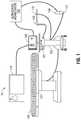
- FIG. 1is a schematic diagram of tracking and treatment system in accordance with an illustrative embodiment of the present disclosure
- FIG. 2is a schematic diagram of a computing device which forms part of the tracking and treatment system 10 of FIG. 1 in accordance with an embodiment of the present disclosure
- FIGS. 3A and 3Bare graphical representations illustrating the treatment probe 130 of FIG. 1 in accordance with embodiments of the present disclosure
- FIGS. 4A-4Gare graphical representations illustrating various sensor mounts for the ultrasound imager 140 of FIG. 1 in accordance with embodiments of the present disclosure
- FIGS. 5A-5Care graphical representations illustrating locking mechanisms for the ultrasound imager 140 of FIG. 1 in accordance with embodiments of the present disclosure.
- FIG. 6is a graphical representation of an image displayed on the display 110 of FIG. 1 in accordance with embodiments of the present disclosure.
- the present disclosureprovides a system for tracking a treatment probe and imaging both the treatment probe and a region of interest in a patient. While performing a surgical treatment, it is important to know exactly where a treatment probe is located within the patient's body, and the location with respect to a target for treatment. In addition, it is beneficial to see an actual image of the treatment probe as it is traversing tissue or entering the target. In this regard, the present disclosure describes location tracking features with which the spatial relationship between the treatment probe and the imaging device can be identified and presented as the treatment probe is navigated to a location within the patient in combination with real-time images of the treatment probe and the target as well as surrounding tissue.
- a treatment planmay be used as a guide during the performance of the surgical procedure, where the system is configured to track the position of treatment probe inside the patient and give the clinician a real-time indication of the position of the treatment probe in relation to the target and the pre-planned pathway toward the target.
- the systemalso presents a clinician with the capability to compare and contrast pre-operative and post-operative CT image data to assess the outcome of a surgical treatment procedure that has been performed.
- a procedure according to the present disclosuresuch as a microwave ablation procedure is generally divided into two phases: (1) a planning phase, and (2) a treatment phase.
- the planning phase of a proceduresuch as microwave ablation treatment, is more fully described in provisional patent application No. 62/035,851 entitled TREATMENT PROCEDURE PLANNING SYSTEM AND METHOD, filed on Aug. 11, 2014 by Bharadwaj et al., the contents of which is hereby incorporated by reference in its entirety.
- An alternative planning or additional planning phase as well as a treatment phaseis more fully described below.
- a tracking and treatment systemmay be a unitary system configured to perform both the planning phase and the treatment phase, or the system may include separate devices and software programs for the various phases.
- An example of the lattermay be a system wherein a first computing device with one or more specialized software programs is used during the planning phase, and a second computing device with one or more specialized software programs may import data from the first computing device to be used during the treatment phase.
- a treatment system 10which includes an EM tracking system 100 , an electrosurgical generator 101 , a workstation 102 , a display 110 , a table 120 , a treatment probe 130 , an ultrasound imager 140 , and an ultrasound workstation 150 .
- the EM tracking system 100may be, for example, a laptop computer, desktop computer, tablet computer, or other similar device.
- the workstation 102may also be used to control a cooling pump or other peripheral devices not expressly shown in FIG. 1 .
- the EM tracking system 100may interact with an EM field generator 121 , one or more tracking sensors 137 and 141 (e.g., an EM sensor, though others could be used), and a display 110 on which a user interface presents the location of the tracking sensors 137 in the EM field in combination with one or more imaging modalities, as will be described in greater detail below.
- the workstation 102includes software which converts signals received from the EM sensors 137 and 141 and performs necessary calculations to track the location of the EM sensors in an EM field.
- the display 110presents to a user the results of the software processing including instructions, images, and messages relating to the performance of the procedure.
- the EM field generator 121rests on or may be built into a table 120 and is located under a patient thus generating an EM field around a portion of the patient through which navigation to a target is desired. Typically this will be the patient's torso which enables navigation to and treatment of all the major organs of the body. However, the same system could be used to treat other locations on the patient.
- An example of such an EM field generator 121is the AURORATM system sold by Northern Digital Inc.
- the electrosurgical generator 101generates electrosurgical energy (e.g., RF or microwave) and provides the generated energy to the treatment probe 130 .
- the treatment probe 130is a surgical instrument, for example, a microwave ablation antenna used to ablate and treat tissue.
- Various other surgical instruments or surgical toolssuch as electrosurgical pencils, vessel sealers, staplers, resection devices and others, may also be used with EM tracking system 100 either with or without an EM sensor 137 .
- located on the treatment probe 130is the tracking sensor 137 as will be described in detail below, allowing for the tracking of the location of the treatment probe 130 in the EM field.
- system 10may be used in alternative settings, for example, at a treatment review board or other office setting such as during a post treatment review of the procedure or assessment of progress of the patient.
- the system 10includes the capabilities for patient, target, and treatment probe 130 visualization using ultrasonic imaging.
- the ultrasound imager 140such as an ultrasonic wand, may be used to image the patient's body during the procedure to visualize the location of the surgical instruments, such as the treatment probe 130 , inside the patient's body.
- the ultrasound imager 140may also have an EM tracking sensor 141 embedded within or attached to the ultrasonic wand, for example, a clip-on sensor or a sticker sensor.
- the ultrasound imager 140may be positioned in relation to the treatment probe 130 such that the treatment probe 130 is at an angle to the ultrasound image plane, thereby enabling the clinician to visualize the spatial relationship of the treatment probe 130 with the ultrasound image plane and with objects being imaged. Further, the EM tracking system 100 may also track the location of ultrasound imager 140 using the EM sensor 141 placed thereon.
- the ultrasound imager 140includes an ultrasound transducer ( 140 a in FIG. 4A ) which emits ultrasound energy receives reflected ultrasound energy. The ultrasound imager 140 then transmits reflected ultrasound waves to the ultrasound workstation 150 , which processes the reflected ultrasound waves and generates ultrasound images.
- the treatment probe 130may be an ablation probe used to ablate a lesion or tumor (hereinafter referred to as a “target”) by using electromagnetic radiation or microwave energy to heat tissue in order to denature or kill cancerous cells.
- a targetused to ablate a lesion or tumor
- the construction and use of a system including such an ablation probeis more fully described in provisional patent application No. 62/041,773 entitled MICROWAVE ABLATION SYSTEM, filed on Aug. 26, 2014, by Dickhans, co-pending patent application Ser. No. 13/836,203 entitled MICROWAVE ABLATION CATHETER AND METHOD OF UTILIZING THE SAME, filed on Mar. 15, 2013, by Latkow et al., and co-pending patent application Ser. No. 13/834,581 entitled MICROWAVE ENERGY-DELIVERY DEVICE AND SYSTEM, filed on Mar. 15, 2013, by Brannan et al., the contents of all of which are hereby incorporated by reference in its entirety.
- the location of the treatment probe 130 within the body of the patientmay be tracked during the surgical procedure using the EM tracking system 101 and the EM sensor 137 located on the treatment probe 130 .
- Various types of sensorsmay be used, such as a printed sensor, the construction and use of which is more fully described in provision patent application No. 62/095,563 entitled MEDICAL INSTRUMENT WITH SENSOR FOR USE IN A SYSTEM AND METHOD FOR ELECTROMAGNETIC NAVIGATION, filed Dec. 22, 2014, the entire contents of which is incorporated herein by reference.
- the clinicianPrior to starting the procedure, the clinician is able to verify the accuracy of the tracking system.
- the workstation 102may combine the ultrasound images from the ultrasound workstation 150 and EM data from the EM tracking system 100 .
- the EM datamay include spatial relationship between the location of the ultrasound imager 140 and the location of the treatment probe 130 in the EM field. Based on the spatial relationship, the workstation 102 generates images depicting the location of the treatment probe 130 with respect to pre-stored images illustrating the treatment probe 130 on display 110 . In addition the workstation 102 generates a representation of the location of the treatment probe in relation to the ultrasound images such that the treatment probe 130 is depicted with respect to the ultrasound image and any pre-planned pathway to a target in the ultrasound image is also displayed allowing the clinician to follow the pathway and achieve the target.
- FIG. 2there is shown a system diagram of a computing device, which can be the EM tracking system 100 , the workstation 102 , or the ultrasound workstation 150 .
- the computing device 200may include memory 202 , processor 204 , the display 206 , network interface 208 , input device 210 , and/or output module 212 .
- Memory 202includes any non-transitory computer-readable storage media for storing data and/or software that is executable by processor 204 and which controls the operation of the computing device 200 .
- memory 202may include one or more solid-state storage devices such as flash memory chips.
- memory 202may include one or more mass storage devices connected to the processor 204 through a mass storage controller (not shown) and a communications bus (not shown).
- mass storage controllernot shown
- communications busnot shown
- computer readable storage mediaincludes non-transitory, volatile and non-volatile, removable and non-removable media implemented in any method or technology for storage of information such as computer-readable instructions, data structures, program modules or other data.
- computer-readable storage mediaincludes RAM, ROM, EPROM, EEPROM, flash memory or other solid state memory technology, CD-ROM, DVD, Blu-Ray or other optical storage, magnetic cassettes, magnetic tape, magnetic disk storage or other magnetic storage devices, or any other medium which can be used to store the desired information and which can be accessed by the computing device 200 .
- Memory 202may store application 216 and/or CT data 214 .
- Application 216may, when executed by processor 204 , cause the display 206 to present user interface 218 .
- Processor 204may be a general purpose processor, a specialized graphics processing unit (GPU) configured to perform specific graphics processing tasks while freeing up the general purpose processor to perform other tasks, and/or any number or combination of such processors.
- GPUgraphics processing unit
- the display 206may be touch-sensitive and/or voice-activated, enabling the display 206 to serve as both an input and output device.
- a keyboardnot shown
- mousenot shown
- other data input devicesmay be employed.
- Network interface 208may be configured to connect to a network such as a local area network (LAN) consisting of a wired network and/or a wireless network, a wide area network (WAN), a wireless mobile network, a Bluetooth network, and/or the internet.
- the computing device 200may receive computed tomographic (CT) image data of a patient from a server, for example, a hospital server, internet server, or other similar servers, for use during surgical ablation planning. Patient CT image data may also be provided to the computing device 200 via a removable memory 202 .
- the computing device 200may receive updates to its software, for example, application 216 , via network interface 208 .
- the computing device 200may also display notifications on the display 206 that a software update is available.
- Input device 210may be any device by means of which a user may interact with the computing device 200 , such as, for example, a mouse, keyboard, foot pedal, touch screen, and/or voice interface.
- Output module 212may include any connectivity port or bus, such as, for example, parallel ports, serial ports, universal serial busses (USB), or any other similar connectivity port known to those skilled in the art.
- connectivity port or bussuch as, for example, parallel ports, serial ports, universal serial busses (USB), or any other similar connectivity port known to those skilled in the art.
- Application 216may be one or more software programs stored in memory 202 and executed by processor 204 of the computing device 200 . During a planning phase, application 216 guides a clinician through a series of steps to identify a target, size the target, size a treatment zone, and/or determine an access route to the target for later use during the procedure phase. In some embodiments, application 216 is loaded on computing devices in an operating room or other facility where surgical procedures are performed, and is used as a plan or map to guide a clinician performing a surgical procedure, but without any feedback from the treatment probe 130 used in the procedure to indicate where the treatment probe 130 is located in relation to the plan
- Application 216may be installed directly on the computing device 200 , or may be installed on another computer, for example a central server, and opened on the computing device 200 via network interface 208 .
- Application 216may run natively on the computing device 200 , as a web-based application, or any other format known to those skilled in the art.
- application 216will be a single software program having all of the features and functionality described in the present disclosure.
- application 216may be two or more distinct software programs providing various parts of these features and functionality.
- application 216may include one software program for use during the planning phase, and a second software program for use during the treatment phase.
- the various software programs forming part of application 216may be enabled to communicate with each other and/or import and export various settings and parameters relating to the navigation and treatment and/or the patient to share information.
- a treatment plan and any of its components generated by one software program during the planning phasemay be stored and exported to be used by a second software program during the procedure phase.
- Application 216communicates with a user interface 218 which generates a user interface for presenting visual interactive features to a clinician, for example, on the display 206 and for receiving clinician input, for example, via a user input device.
- user interface 218may generate a graphical user interface (GUI) and output the GUI to the display 206 for viewing by a clinician.
- GUIgraphical user interface
- the computing device 200may be linked to the display 110 , thus enabling the computing device 200 to control the output on the display 110 along with the output on the display 206 .
- the computing device 200may control the display 110 to display output which is the same as or similar to the output displayed on the display 206 .
- the output on the display 206may be mirrored on the display 110 .
- the computing device 200may control the display 110 to display different output from that displayed on the display 206 .
- the display 110may be controlled to display guidance images and information during the surgical procedure, while the display 206 is controlled to display other output, such as configuration or status information of an electrosurgical generator 101 as shown in FIG. 1 .
- clinical practicerefers to any medical professional (i.e., doctor, surgeon, nurse, or the like) or other user of the system 10 involved in performing, monitoring, and/or supervising a medical procedure involving the use of the embodiments described herein.
- FIGS. 3A and 3Bprovide one solution for addressing this issue without the need to alter an existing treatment probe 130 .
- FIG. 3Adepicts a hub 131 which can be placed around existing treatment probes, such as the EmprintTM ablation probe currently sold by Medtronic PLC, in order to secure the EM tracking sensors 137 and to enable the use of such a device in an EM field of the system 10 .
- the hub 131includes a cannula 132 and first and second locking member 134 and 135 , respectively. As shown in FIG. 3A , a portion of the shaft 133 of the treatment probe 130 extends beyond the distal end of the hub 131 allowing for effective use of the treatment probe 130 .
- the treatment probe 130is secured in the hub 131 by the cannula 132 , the first locking member 134 , which prevents the axial movements of the treatment probe 130 , and the second locking member 135 prevents rotational movement of the treatment probe 130 , relative to the hub 131 .
- the first and second locking members 134 and 135may be clip-type locks or any locking devices suitable to lock movements of the treatment probe 130 relative to the hub 131 .
- FIG. 3Bthere is shown an expanded view of the cannula 132 of the hub 131 with the shaft 133 of the treatment probe 130 extending therefrom.
- the cannula 132has three parts, a proximal part 132 a , a middle part 132 b , and a distal part 132 c .
- the proximal part 132 a and the distal part 132 care rigid and the middle part 132 b is flexible.
- the flexible middle part 132 bhelps eliminate any stress that the hub 131 might place on the shaft 133 of the treatment probe 130 .
- the hub 131may be made of a less flexible material than the shaft 133 of the treatment probe, thus when placed in the hub 131 normal operation of the treatment probe 130 might induce stresses in the shaft 133 at the locations identified as 136 in FIG. 3B .
- the flexible middle part 132 bBy adding the flexible middle part 132 b , these stresses are reduced and the potential for damaging the treatment probe 130 is also reduced.
- an EM tracking sensor 137is affixed at the distal part 132 c of the cannula 132 .
- the EM tracking sensor 137outputs a voltage (or multiple voltages) that can be sensed by the EM tracking system 100 and converted into location information of the EM tracking sensor 137 in the EM field generated by the EM field generator 121 to identify the location of the EM tracking sensor 137 or the distal part 132 c within an EM field, and therewith the location of the EM tracking sensor 137 with respect to the patient.
- one or more of the software applications running on the EM tracking system 100determine the location of the distal end of the treatment probe 130 , and generate a representation of its location on the display based on the sensed location of the EM tracking sensor 137 .
- This representationcan be used to assist in navigating to a desired point in the patient as depicted in either two-dimensional images or a three-dimensional model of a desired portion of the patient.
- the system 10may display a virtual image of the shaft 133 overlaid over an ultrasound image on the display 110 .
- the distal part 132 c including the EM tracking sensor 137moves along with the navigation of the shaft 133 .
- flexibility of the middle part 132 balso increases detection accuracy of the current location of the shaft 133 and prevent the shaft 133 from breaking due to the stress.
- the EM tracking sensor 137may be rigidly affixed by an adhesive or by other suitable means which do not interfere with the EM field and the frequency employed by the treatment probe 130 , may be used.
- the EM tracking sensor 137may be printed on the cannula 132 at a predetermined position.
- FIGS. 4A-4Gthere are shown various sensor mounts for the ultrasound imager 140 to provide location information about the ultrasound imager 140 to the EM tracking system 100 to provide real time images of the patient while the clinician navigates the treatment probe 130 to a desired location.
- These sensor mountsare to enable the use of off the shelf ultrasound probes with the system 10 , thus enabling clinicians to utilize their preferred imaging systems and probes and integrate them into system 10 .
- FIG. 4Ashows the ultrasound imager 140 , an EM tracking sensor 141 , and a sensor mount 142 .
- the ultrasound imager 140includes an ultrasound transducer 140 a which emits ultrasound energy and receives reflected ultrasound energy.
- the received ultrasound energyis then transmitted to an image processing device such as the ultrasound workstation 150 , which calculates and processes the reflected ultrasound energy to generate real-time ultrasound images and transmits to the workstation 102 .
- an image processing devicesuch as the ultrasound workstation 150
- the imagesmay include the shaft 133 , a target region for treatment, and other internal organs.
- the processed real-time imagesare displayed on the display 110 .
- the ultrasound imager 140may include a smooth round-shape at its distal tip 140 b and/or a cut-out portion 140 c in the middle thereof.
- the cut-out portion 140 cmay have an inclination from the top surface toward the center.
- the inclinationhas an angle ⁇ with respect to the longitudinal axis, which is greater than zero degrees and less than 90 degrees.
- the EM tracking sensor 141is mounted inside of a sensor mount 142 which may slidably and releasably engage with the distal tip 140 b .
- the sensor mount 142includes a locking mechanism, which will be described below in FIGS. 4E-4H .
- the locking mechanismmakes a locking engagement sufficiently strong enough so that the ultrasound imager 140 can navigate inside of the patient's body without risks of removal of the sensor mount 142 .
- the material of the sensor mount 142should not hinder propagation and reception of the ultrasound energy by the ultrasound transducer 140 a.
- the position of the EM tracking sensor 141may be predetermined to have a spatial relationship between the EM tracking sensor 141 and the distal tip 140 b of the ultrasound imager 140 .
- the EM tracking system 100is able to identify the location of the distal tip 140 b based on the spatial relationship and the detected location of the EM tracking sensor 141 .
- the location of the ultrasound imager 140 in space, and more particularly within or over the patientcan be determined such that the ultrasound image plane generated by the ultrasound imager 140 can be determined, compared, and correlated to the location of the treatment probe 130 .
- the material of the sensor mount 142may not hinder propagation and reception of the ultrasonic waves by the ultrasound transducer 140 a.
- FIG. 4Bthere is shown a sensor mount 143 , which is a top cap version.
- the sensor mount 143engages with the ultrasound imager 140 from the top or at the inclination of the ultrasound imager 140 . Since the inclination has the angle ⁇ , the top portion of the sensor mount 143 also has an inclination having the angle ⁇ with respect to the longitudinal axis of the ultrasound transducer 140 a , they fit to each other. Also, the inclinations of the sensor mount 143 and the cut-out portion 140 c make possible to align the EM tracking sensor 141 with an angle with which the ultrasound imager 140 transmits ultrasonic waves.
- the position in the sensor mount 143may be predetermined to set a spatial relationship between the EM tracking sensor 141 and the ultrasound transducer 140 a . It will be appreciated by those of skill in the art that extending from the sensor mounts 142 and 143 are wires which are used to connect the EM tracking sensor 141 to the EM tracking system 100 such that the location of the EM tracking sensor 141 in the EM field can be determined.
- the hypotube 146 as a sensor mountmay have four fingers that grab the cut-out portion 140 c ( FIG. 4A ) of the ultrasound imager 140 and may cover a portion of the bottom and the side of the ultrasound imager 140 .
- the EM tracking sensor 141may be between the hypotube 146 and the ultrasound imager 140 , or may be affixed at a predetermined position on the outside surface of the hypotube 146 .
- the hypotube 146is made of materials, which decreases neither the sensitivity of the EM tracking sensor 141 in the EM field nor the quality of ultrasound images obtained by the ultrasound transducer 140 a.
- the hypotube 147 of FIG. 4Dincludes all the features of the hypotube 146 of FIG. 4C and further includes a distal cap 147 a covering a portion of the distal tip 140 b of the ultrasound imager 140 .
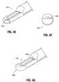
- FIGS. 4E-4Gthere are shown sensor mounts, which are hypotube clips.
- FIG. 4Eshows a perspective view
- FIG. 4Fshows a transverse view of the ultrasound imager 140 .
- the hypotube clip 148may be connected with the ultrasound imager 140 from the side of the ultrasound transducer 140 a .
- the hypotube clip 148may include two clip tabs, which are bent flat to match the profile of the ultrasound transducer 140 a .
- the EM tracking sensor 141may be affixed at a predetermined position on the hypotube clip 148 .
- the clip tabs 148 amay lock the EM tracking sensor 141 in the circumferential direction.
- the hypotube clip 149 of FIG. 4Gincludes only one clip tab 149 a at the proximal end of the ultrasound transducer 140 a and a cap 149 b at the distal end of the ultrasound transducer 140 a which covers the distal tip 140 b .
- the cap 149 bmay embed the EM tracking sensor 141 .
- the clip tab 194 a and the cap 149 b togethermay prevent a shift movement along the longitudinal direction so that the position of the EM tracking sensor 141 can be consistent with respect to the distal tip of the ultrasound imager 140 .
- one of the issues with connecting the EM tracking sensor 141 to the ultrasound imager 140is to ensure that the EM tracking sensor 141 does not interfere with the ultrasound transducer 140 a . Accordingly, all the preceding embodiments focused on placing the EM tracking sensor 141 near the ultrasound transducer 140 a but not on the ultrasound transducer 140 a . An alternative approach would be to adhere the EM tracking sensor 141 to the ultrasound transducer 140 a using a phantom material, which does not interfere with the transducer's imaging capabilities.
- the effectis similar to that of affixing the EM tracking sensor 141 directly to the ultrasound imager 140 .
- FIG. 5Athere is shown a locking mechanism for connecting the ultrasound imager 140 to a cannula 170 .
- the shaft of an ultrasound imager 140can be locked into the cannula 170 using a John-Guest (JG) collet, which includes an inner tube 171 and an outer tube 172 .
- JGJohn-Guest
- the outer tube 172compresses the inner tube 171 .
- the teeth of the inner tube 171grab the ultrasound imager 140 holding it in place with respect to the cannula 170 .
- FIG. 5BAn alternative approach is shown in FIG. 5B , there is shown a Tuohy-Borst type locking mechanism 180 which can be used to lock a cannula 170 to the ultrasound imager 140 using an O-ring.
- the locking mechanism 180includes a front end 180 a and an O-ring 180 b .
- the locking mechanismis locate on a proximal end of a cannula 170 and the ultrasound imager is inserted into the cannula and locked into place by rotating the front end 180 a such that the O-ring type is compressed locking the cannula 170 to the ultrasound imager 140 .
- Rotation of the front end 180 a in the opposite directionreleases the pressure applied by the O-ring to the ultrasound imager 140 and allows for its removal from the cannula 170 .
- the cannula 190may include a flexible middle portion 190 a , which in combination with a D-shape 190 b at the distal end allows for the ultrasound imager 140 to self-align in the cannula 190 and have flexibility of motion.
- the D-shape 190 ballows for the accommodation of a 4-way ultrasound transducer.
- the EM sensor 137may be formed directly on the cannula 190 . As a result of the self-alignment enabled by the D-shape, the orientation of the EM sensor 137 and the ultrasound imager 140 placed therein (and not shown in FIG.
- the EM sensor 137may be connected via a wire to the EM tracking system 100 as shown in FIG. 1 .
- the wiremay run internally or externally of the cannula 190 , and may be modified to accommodate the flexure of the cannula 190 .
- FIG. 6shows a graphical interface 600 displayed on the display 110 of FIG. 1 .
- the display 110displays an ultrasound image 602 , the left side image, received from the ultrasound workstation 150 and also shows two indications 604 and 606 informing that an antenna tracker and an ultrasound tracker are activated and being tracked.
- Right side image 612is a composite of image 600 illustrating the progression of a treatment, here microwave ablation.
- Indication 610may shows that an ablation treatment has started.
- the treatment probe 130is displayed as generated image 614 , its location and orientation on the image having been determined by the special relationship between the treatment probe 130 and the ultrasound probe 140 , as described above.
- a treatment region 618shows the tissue which has been treated, while target region 620 depicts the entire region to be treated.
- the tip 614 a of the treatment probe 130is displayed being inserted to the target region.
- Other textual information 616 and 608may be displayed to show power being applied to the treatment probe 130 and the temperature of the treatment probe 130 or tissue proxi
Landscapes
- Health & Medical Sciences (AREA)
- Life Sciences & Earth Sciences (AREA)
- Medical Informatics (AREA)
- Biophysics (AREA)
- Nuclear Medicine, Radiotherapy & Molecular Imaging (AREA)
- Pathology (AREA)
- Radiology & Medical Imaging (AREA)
- Engineering & Computer Science (AREA)
- Biomedical Technology (AREA)
- Heart & Thoracic Surgery (AREA)
- Physics & Mathematics (AREA)
- Molecular Biology (AREA)
- Surgery (AREA)
- Animal Behavior & Ethology (AREA)
- General Health & Medical Sciences (AREA)
- Public Health (AREA)
- Veterinary Medicine (AREA)
- Vascular Medicine (AREA)
- Ultra Sonic Daignosis Equipment (AREA)
- Surgical Instruments (AREA)
Abstract
Description
Claims (20)
Priority Applications (9)
| Application Number | Priority Date | Filing Date | Title |
|---|---|---|---|
| US14/930,900US10869650B2 (en) | 2014-11-06 | 2015-11-03 | System for tracking and imaging a treatment probe |
| CN201580061112.0ACN107106129B (en) | 2014-11-06 | 2015-11-06 | System for tracking and imaging processing probes |
| AU2015342868AAU2015342868B2 (en) | 2014-11-06 | 2015-11-06 | System for tracking and imaging a treatment probe |
| PCT/US2015/059511WO2016073876A1 (en) | 2014-11-06 | 2015-11-06 | System for tracking and imaging a treatment probe |
| CA2967000ACA2967000A1 (en) | 2014-11-06 | 2015-11-06 | System for tracking and imaging a treatment probe |
| JP2017523440AJP6599459B2 (en) | 2014-11-06 | 2015-11-06 | System for tracking and imaging a treatment probe |
| EP15856682.8AEP3215020B1 (en) | 2014-11-06 | 2015-11-06 | System for tracking and imaging a treatment probe |
| US16/951,194US11771401B2 (en) | 2014-11-06 | 2020-11-18 | System for tracking and imaging a treatment probe |
| US18/474,431US12257105B2 (en) | 2014-11-06 | 2023-09-26 | System for tracking and imaging a treatment probe |
Applications Claiming Priority (2)
| Application Number | Priority Date | Filing Date | Title |
|---|---|---|---|
| US201462076132P | 2014-11-06 | 2014-11-06 | |
| US14/930,900US10869650B2 (en) | 2014-11-06 | 2015-11-03 | System for tracking and imaging a treatment probe |
Related Child Applications (1)
| Application Number | Title | Priority Date | Filing Date |
|---|---|---|---|
| US16/951,194ContinuationUS11771401B2 (en) | 2014-11-06 | 2020-11-18 | System for tracking and imaging a treatment probe |
Publications (2)
| Publication Number | Publication Date |
|---|---|
| US20160128669A1 US20160128669A1 (en) | 2016-05-12 |
| US10869650B2true US10869650B2 (en) | 2020-12-22 |
Family
ID=55909873
Family Applications (3)
| Application Number | Title | Priority Date | Filing Date |
|---|---|---|---|
| US14/930,900Active2037-01-01US10869650B2 (en) | 2014-11-06 | 2015-11-03 | System for tracking and imaging a treatment probe |
| US16/951,194Active2036-08-10US11771401B2 (en) | 2014-11-06 | 2020-11-18 | System for tracking and imaging a treatment probe |
| US18/474,431ActiveUS12257105B2 (en) | 2014-11-06 | 2023-09-26 | System for tracking and imaging a treatment probe |
Family Applications After (2)
| Application Number | Title | Priority Date | Filing Date |
|---|---|---|---|
| US16/951,194Active2036-08-10US11771401B2 (en) | 2014-11-06 | 2020-11-18 | System for tracking and imaging a treatment probe |
| US18/474,431ActiveUS12257105B2 (en) | 2014-11-06 | 2023-09-26 | System for tracking and imaging a treatment probe |
Country Status (7)
| Country | Link |
|---|---|
| US (3) | US10869650B2 (en) |
| EP (1) | EP3215020B1 (en) |
| JP (1) | JP6599459B2 (en) |
| CN (1) | CN107106129B (en) |
| AU (1) | AU2015342868B2 (en) |
| CA (1) | CA2967000A1 (en) |
| WO (1) | WO2016073876A1 (en) |
Cited By (2)
| Publication number | Priority date | Publication date | Assignee | Title |
|---|---|---|---|---|
| US11369340B2 (en)* | 2016-09-30 | 2022-06-28 | Koninklijke Philips N.V. | Tracking a feature of an interventional device |
| US11771401B2 (en) | 2014-11-06 | 2023-10-03 | Covidien Lp | System for tracking and imaging a treatment probe |
Families Citing this family (10)
| Publication number | Priority date | Publication date | Assignee | Title |
|---|---|---|---|---|
| US20170319174A1 (en)* | 2016-05-04 | 2017-11-09 | Covidien Lp | Systems for sensing position of imaging device |
| EP3612100A1 (en)* | 2017-04-19 | 2020-02-26 | Deutsches Krebsforschungszentrum | Mounting device for reversibly mounting an electromagnetic field generator on an ultrasonic probe |
| US10874327B2 (en) | 2017-05-19 | 2020-12-29 | Covidien Lp | Systems and methods for tracking and imaging a treatment probe having an integrated sensor |
| US10925628B2 (en) | 2017-09-18 | 2021-02-23 | Novuson Surgical, Inc. | Tissue engagement apparatus for theapeutic ultrasound apparatus and method |
| US11648062B2 (en)* | 2017-11-09 | 2023-05-16 | Acessa Health Inc. | System for controlling ablation treatment and visualization |
| US20190262082A1 (en)* | 2018-02-26 | 2019-08-29 | Covidien Lp | System and method for performing a percutaneous navigation procedure |
| US11701492B2 (en) | 2020-06-04 | 2023-07-18 | Covidien Lp | Active distal tip drive |
| CN111920453B (en)* | 2020-08-14 | 2024-12-20 | 中国科学院苏州生物医学工程技术研究所 | In-vivo interventional ultrasound probe with rotational positioning and ultrasound imaging system containing the same |
| CN117642123A (en)* | 2021-08-31 | 2024-03-01 | 豪雅株式会社 | Endoscope with removable sensor |
| WO2024112808A1 (en)* | 2022-11-21 | 2024-05-30 | Nuvaira, Inc. | Utilization of three-dimensional navigation technology during lung denervation procedures |
Citations (48)
| Publication number | Priority date | Publication date | Assignee | Title |
|---|---|---|---|---|
| US3868565A (en) | 1973-07-30 | 1975-02-25 | Jack Kuipers | Object tracking and orientation determination means, system and process |
| US3983474A (en) | 1975-02-21 | 1976-09-28 | Polhemus Navigation Sciences, Inc. | Tracking and determining orientation of object using coordinate transformation means, system and process |
| US4017858A (en) | 1973-07-30 | 1977-04-12 | Polhemus Navigation Sciences, Inc. | Apparatus for generating a nutating electromagnetic field |
| US4054881A (en) | 1976-04-26 | 1977-10-18 | The Austin Company | Remote object position locater |
| US4287809A (en) | 1979-08-20 | 1981-09-08 | Honeywell Inc. | Helmet-mounted sighting system |
| US4314251A (en) | 1979-07-30 | 1982-02-02 | The Austin Company | Remote object position and orientation locater |
| US4328548A (en) | 1980-04-04 | 1982-05-04 | The Austin Company | Locator for source of electromagnetic radiation having unknown structure or orientation |
| US4346384A (en) | 1980-06-30 | 1982-08-24 | The Austin Company | Remote object position and orientation locator |
| US4394831A (en) | 1981-02-12 | 1983-07-26 | Honeywell Inc. | Helmet metal mass compensation for helmet-mounted sighting system |
| US4396885A (en) | 1979-06-06 | 1983-08-02 | Thomson-Csf | Device applicable to direction finding for measuring the relative orientation of two bodies |
| US4582066A (en)* | 1983-02-02 | 1986-04-15 | Lawrence Medical Systems, Inc. | Ultrasonic transducer probe |
| US4613866A (en) | 1983-05-13 | 1986-09-23 | Mcdonnell Douglas Corporation | Three dimensional digitizer with electromagnetic coupling |
| US4710708A (en) | 1981-04-27 | 1987-12-01 | Develco | Method and apparatus employing received independent magnetic field components of a transmitted alternating magnetic field for determining location |
| US4737794A (en) | 1985-12-09 | 1988-04-12 | Mcdonnell Douglas Corporation | Method and apparatus for determining remote object orientation and position |
| US4742356A (en) | 1985-12-09 | 1988-05-03 | Mcdonnell Douglas Corporation | Method and apparatus for determining remote object orientation and position |
| US4849692A (en) | 1986-10-09 | 1989-07-18 | Ascension Technology Corporation | Device for quantitatively measuring the relative position and orientation of two bodies in the presence of metals utilizing direct current magnetic fields |
| US4877033A (en)* | 1988-05-04 | 1989-10-31 | Seitz Jr H Michael | Disposable needle guide and examination sheath for transvaginal ultrasound procedures |
| WO1994004938A1 (en) | 1992-08-14 | 1994-03-03 | British Telecommunications Public Limited Company | Position location system |
| US5307072A (en) | 1992-07-09 | 1994-04-26 | Polhemus Incorporated | Non-concentricity compensation in position and orientation measurement systems |
| US5377678A (en) | 1991-09-03 | 1995-01-03 | General Electric Company | Tracking system to follow the position and orientation of a device with radiofrequency fields |
| WO1996005768A1 (en) | 1994-08-19 | 1996-02-29 | Biosense, Inc. | Medical diagnosis, treatment and imaging systems |
| US5503154A (en)* | 1994-10-13 | 1996-04-02 | Cardiovascular Imaging Systems, Inc. | Transducer for intraluminal ultrasound imaging catheter with provision for electrical isolation of transducer from the catheter core |
| US5600330A (en) | 1994-07-12 | 1997-02-04 | Ascension Technology Corporation | Device for measuring position and orientation using non-dipole magnet IC fields |
| US5646525A (en) | 1992-06-16 | 1997-07-08 | Elbit Ltd. | Three dimensional tracking system employing a rotating field |
| US5729129A (en) | 1995-06-07 | 1998-03-17 | Biosense, Inc. | Magnetic location system with feedback adjustment of magnetic field generator |
| US5752513A (en) | 1995-06-07 | 1998-05-19 | Biosense, Inc. | Method and apparatus for determining position of object |
| EP0922966A2 (en) | 1997-12-12 | 1999-06-16 | Super Dimension Ltd. | Wireless six-degree-of-freedom locator |
| WO1999032033A1 (en) | 1997-12-22 | 1999-07-01 | Cormedica Corporation | Measuring position and orientation using magnetic fields |
| US5993437A (en)* | 1998-01-15 | 1999-11-30 | Epimed International, Inc. | Catheter connector |
| US6375615B1 (en) | 1995-10-13 | 2002-04-23 | Transvascular, Inc. | Tissue penetrating catheters having integral imaging transducers and their methods of use |
| US20020107445A1 (en) | 1999-03-11 | 2002-08-08 | Assaf Govari | Implantable and insertable passive tags |
| US6615155B2 (en) | 2000-03-09 | 2003-09-02 | Super Dimension Ltd. | Object tracking using a single sensor or a pair of sensors |
| US6695772B1 (en)* | 2001-11-26 | 2004-02-24 | Visionary Biomedical, Inc. | Small diameter cannula devices, systems and methods |
| US20040049111A1 (en)* | 1999-12-08 | 2004-03-11 | Olympus Optical Co., Ltd. | Ultrasonic probe for operation under microscope |
| US20040254458A1 (en) | 2003-05-29 | 2004-12-16 | Assaf Govari | Ultrasound catheter calibration system |
| JP2005058584A (en) | 2003-08-19 | 2005-03-10 | Toshiba Corp | Ultrasonic diagnostic equipment |
| US20050090742A1 (en) | 2003-08-19 | 2005-04-28 | Yoshitaka Mine | Ultrasonic diagnostic apparatus |
| US20070167787A1 (en)* | 2005-06-21 | 2007-07-19 | Glossop Neil D | Device and method for a trackable ultrasound |
| US20090266957A1 (en) | 2008-04-29 | 2009-10-29 | Civco Medical Instruments Co., Inc. | Bracket for mounting at least one position detecting sensor on an ultrasonic probe |
| CN101569556A (en) | 2009-05-25 | 2009-11-04 | 深圳市第二人民医院 | Laparoscope holding fixer |
| US20090275833A1 (en)* | 2005-10-04 | 2009-11-05 | Takashi Ikeda | Ultrasonic probe and ultrasonic diagnostic apparatus employing the same |
| US20100081920A1 (en)* | 2008-09-29 | 2010-04-01 | Civco Medical Instruments Co., Inc. | Em tracking systems for use with ultrasound and other imaging modalities |
| US20100298704A1 (en) | 2009-05-20 | 2010-11-25 | Laurent Pelissier | Freehand ultrasound imaging systems and methods providing position quality feedback |
| US20120143055A1 (en)* | 2010-12-01 | 2012-06-07 | General Electric Company | Method and system for ultrasound imaging |
| US20140081659A1 (en)* | 2012-09-17 | 2014-03-20 | Depuy Orthopaedics, Inc. | Systems and methods for surgical and interventional planning, support, post-operative follow-up, and functional recovery tracking |
| US20140121502A1 (en) | 2011-07-01 | 2014-05-01 | Koninklijke Philips N.V. | Object-pose-based initialization of an ultrasound beamformer |
| KR20160064574A (en) | 2014-11-28 | 2016-06-08 | 한국과학기술연구원 | HIFU(high intensity focused ultrasound) THERAPY SYSTEM AND METHOD |
| US20170319174A1 (en)* | 2016-05-04 | 2017-11-09 | Covidien Lp | Systems for sensing position of imaging device |
Family Cites Families (13)
| Publication number | Priority date | Publication date | Assignee | Title |
|---|---|---|---|---|
| US6505062B1 (en)* | 1998-02-09 | 2003-01-07 | Stereotaxis, Inc. | Method for locating magnetic implant by source field |
| JP4772540B2 (en)* | 2006-03-10 | 2011-09-14 | 株式会社東芝 | Ultrasonic diagnostic equipment |
| CN100548215C (en)* | 2007-01-30 | 2009-10-14 | 华南师范大学 | A kind of method and device thereof that utilizes thermal acoustic imaging to detect foreign body |
| WO2009120953A2 (en)* | 2008-03-27 | 2009-10-01 | Mayo Foundation For Medical Education And Research | Navigation and tissue capture systems and methods |
| US20110184684A1 (en)* | 2009-07-21 | 2011-07-28 | Eigen, Inc. | 3-d self-correcting freehand ultrasound tracking system |
| US9993295B2 (en)* | 2012-08-07 | 2018-06-12 | Covidien Lp | Microwave ablation catheter and method of utilizing the same |
| CN104602626B (en)* | 2012-08-28 | 2018-03-02 | 皇家飞利浦有限公司 | Interventional guidance system with integrated tracking setup |
| US20140187980A1 (en)* | 2012-12-28 | 2014-07-03 | Volcano Corporation | Hypotube Sensor Mount for Sensored Guidewire |
| CN203324229U (en)* | 2013-06-27 | 2013-12-04 | 苏州边枫电子科技有限公司 | Puncture needle detection device based on ultrasonic detection |
| EP3019088B1 (en)* | 2013-07-08 | 2020-12-02 | Koninklijke Philips N.V. | Imaging apparatus for biopsy or brachytherapy |
| US10869650B2 (en) | 2014-11-06 | 2020-12-22 | Covidien Lp | System for tracking and imaging a treatment probe |
| WO2022216862A1 (en)* | 2021-04-06 | 2022-10-13 | Boston Scientific Scimed, Inc. | Devices, systems, and methods for positioning medical devices within a body lumen |
| US20220378513A1 (en)* | 2021-05-27 | 2022-12-01 | Covidien Lp | Locking and drive mechanisms for positioning and stabilization of catheters and endoscopic tools |
- 2015
- 2015-11-03USUS14/930,900patent/US10869650B2/enactiveActive
- 2015-11-06WOPCT/US2015/059511patent/WO2016073876A1/enactiveApplication Filing
- 2015-11-06JPJP2017523440Apatent/JP6599459B2/ennot_activeExpired - Fee Related
- 2015-11-06AUAU2015342868Apatent/AU2015342868B2/ennot_activeCeased
- 2015-11-06CACA2967000Apatent/CA2967000A1/ennot_activeAbandoned
- 2015-11-06EPEP15856682.8Apatent/EP3215020B1/enactiveActive
- 2015-11-06CNCN201580061112.0Apatent/CN107106129B/enactiveActive
- 2020
- 2020-11-18USUS16/951,194patent/US11771401B2/enactiveActive
- 2023
- 2023-09-26USUS18/474,431patent/US12257105B2/enactiveActive
Patent Citations (49)
| Publication number | Priority date | Publication date | Assignee | Title |
|---|---|---|---|---|
| US3868565A (en) | 1973-07-30 | 1975-02-25 | Jack Kuipers | Object tracking and orientation determination means, system and process |
| US4017858A (en) | 1973-07-30 | 1977-04-12 | Polhemus Navigation Sciences, Inc. | Apparatus for generating a nutating electromagnetic field |
| US3983474A (en) | 1975-02-21 | 1976-09-28 | Polhemus Navigation Sciences, Inc. | Tracking and determining orientation of object using coordinate transformation means, system and process |
| US4054881A (en) | 1976-04-26 | 1977-10-18 | The Austin Company | Remote object position locater |
| US4396885A (en) | 1979-06-06 | 1983-08-02 | Thomson-Csf | Device applicable to direction finding for measuring the relative orientation of two bodies |
| US4314251A (en) | 1979-07-30 | 1982-02-02 | The Austin Company | Remote object position and orientation locater |
| US4287809A (en) | 1979-08-20 | 1981-09-08 | Honeywell Inc. | Helmet-mounted sighting system |
| US4328548A (en) | 1980-04-04 | 1982-05-04 | The Austin Company | Locator for source of electromagnetic radiation having unknown structure or orientation |
| US4346384A (en) | 1980-06-30 | 1982-08-24 | The Austin Company | Remote object position and orientation locator |
| US4394831A (en) | 1981-02-12 | 1983-07-26 | Honeywell Inc. | Helmet metal mass compensation for helmet-mounted sighting system |
| US4710708A (en) | 1981-04-27 | 1987-12-01 | Develco | Method and apparatus employing received independent magnetic field components of a transmitted alternating magnetic field for determining location |
| US4582066A (en)* | 1983-02-02 | 1986-04-15 | Lawrence Medical Systems, Inc. | Ultrasonic transducer probe |
| US4613866A (en) | 1983-05-13 | 1986-09-23 | Mcdonnell Douglas Corporation | Three dimensional digitizer with electromagnetic coupling |
| US4737794A (en) | 1985-12-09 | 1988-04-12 | Mcdonnell Douglas Corporation | Method and apparatus for determining remote object orientation and position |
| US4742356A (en) | 1985-12-09 | 1988-05-03 | Mcdonnell Douglas Corporation | Method and apparatus for determining remote object orientation and position |
| US4849692A (en) | 1986-10-09 | 1989-07-18 | Ascension Technology Corporation | Device for quantitatively measuring the relative position and orientation of two bodies in the presence of metals utilizing direct current magnetic fields |
| US4877033A (en)* | 1988-05-04 | 1989-10-31 | Seitz Jr H Michael | Disposable needle guide and examination sheath for transvaginal ultrasound procedures |
| US5377678A (en) | 1991-09-03 | 1995-01-03 | General Electric Company | Tracking system to follow the position and orientation of a device with radiofrequency fields |
| US5646525A (en) | 1992-06-16 | 1997-07-08 | Elbit Ltd. | Three dimensional tracking system employing a rotating field |
| US5307072A (en) | 1992-07-09 | 1994-04-26 | Polhemus Incorporated | Non-concentricity compensation in position and orientation measurement systems |
| WO1994004938A1 (en) | 1992-08-14 | 1994-03-03 | British Telecommunications Public Limited Company | Position location system |
| US5600330A (en) | 1994-07-12 | 1997-02-04 | Ascension Technology Corporation | Device for measuring position and orientation using non-dipole magnet IC fields |
| WO1996005768A1 (en) | 1994-08-19 | 1996-02-29 | Biosense, Inc. | Medical diagnosis, treatment and imaging systems |
| US5503154A (en)* | 1994-10-13 | 1996-04-02 | Cardiovascular Imaging Systems, Inc. | Transducer for intraluminal ultrasound imaging catheter with provision for electrical isolation of transducer from the catheter core |
| US5729129A (en) | 1995-06-07 | 1998-03-17 | Biosense, Inc. | Magnetic location system with feedback adjustment of magnetic field generator |
| US5752513A (en) | 1995-06-07 | 1998-05-19 | Biosense, Inc. | Method and apparatus for determining position of object |
| US6375615B1 (en) | 1995-10-13 | 2002-04-23 | Transvascular, Inc. | Tissue penetrating catheters having integral imaging transducers and their methods of use |
| EP0922966A2 (en) | 1997-12-12 | 1999-06-16 | Super Dimension Ltd. | Wireless six-degree-of-freedom locator |
| WO1999032033A1 (en) | 1997-12-22 | 1999-07-01 | Cormedica Corporation | Measuring position and orientation using magnetic fields |
| US5993437A (en)* | 1998-01-15 | 1999-11-30 | Epimed International, Inc. | Catheter connector |
| US20020107445A1 (en) | 1999-03-11 | 2002-08-08 | Assaf Govari | Implantable and insertable passive tags |
| US20040049111A1 (en)* | 1999-12-08 | 2004-03-11 | Olympus Optical Co., Ltd. | Ultrasonic probe for operation under microscope |
| US6615155B2 (en) | 2000-03-09 | 2003-09-02 | Super Dimension Ltd. | Object tracking using a single sensor or a pair of sensors |
| US6695772B1 (en)* | 2001-11-26 | 2004-02-24 | Visionary Biomedical, Inc. | Small diameter cannula devices, systems and methods |
| US20040254458A1 (en) | 2003-05-29 | 2004-12-16 | Assaf Govari | Ultrasound catheter calibration system |
| JP2005058584A (en) | 2003-08-19 | 2005-03-10 | Toshiba Corp | Ultrasonic diagnostic equipment |
| US20050090742A1 (en) | 2003-08-19 | 2005-04-28 | Yoshitaka Mine | Ultrasonic diagnostic apparatus |
| US20070167787A1 (en)* | 2005-06-21 | 2007-07-19 | Glossop Neil D | Device and method for a trackable ultrasound |
| US20090275833A1 (en)* | 2005-10-04 | 2009-11-05 | Takashi Ikeda | Ultrasonic probe and ultrasonic diagnostic apparatus employing the same |
| US20090266957A1 (en) | 2008-04-29 | 2009-10-29 | Civco Medical Instruments Co., Inc. | Bracket for mounting at least one position detecting sensor on an ultrasonic probe |
| US20100081920A1 (en)* | 2008-09-29 | 2010-04-01 | Civco Medical Instruments Co., Inc. | Em tracking systems for use with ultrasound and other imaging modalities |
| US20100298704A1 (en) | 2009-05-20 | 2010-11-25 | Laurent Pelissier | Freehand ultrasound imaging systems and methods providing position quality feedback |
| CN101569556A (en) | 2009-05-25 | 2009-11-04 | 深圳市第二人民医院 | Laparoscope holding fixer |
| US20120143055A1 (en)* | 2010-12-01 | 2012-06-07 | General Electric Company | Method and system for ultrasound imaging |
| CN102525558A (en) | 2010-12-01 | 2012-07-04 | 通用电气公司 | Method and system for ultrasound imaging |
| US20140121502A1 (en) | 2011-07-01 | 2014-05-01 | Koninklijke Philips N.V. | Object-pose-based initialization of an ultrasound beamformer |
| US20140081659A1 (en)* | 2012-09-17 | 2014-03-20 | Depuy Orthopaedics, Inc. | Systems and methods for surgical and interventional planning, support, post-operative follow-up, and functional recovery tracking |
| KR20160064574A (en) | 2014-11-28 | 2016-06-08 | 한국과학기술연구원 | HIFU(high intensity focused ultrasound) THERAPY SYSTEM AND METHOD |
| US20170319174A1 (en)* | 2016-05-04 | 2017-11-09 | Covidien Lp | Systems for sensing position of imaging device |
Non-Patent Citations (10)
| Title |
|---|
| "Hypotube Definition," Jul. 27, 2014, Modern Grinding <http://www.moderngrinding.com/hypotube-definition.php>.* |
| "New Hypotube for PTCA Catheters launched," Feb. 1, 2006, Creganna Medical Devices <http://www.creganna.com/new-hypotube-for-ptca-catheters-launched/>.* |
| "Oxy Clip Cylinder Holder," Nov. 1, 2013, Ferno <http://www.fernoems.com/en/powerflexx/Oxy-Clip-Cylinder-Holder.aspx>.* |
| Australian Examination Report issued in corresponding Appl. No. AU 2015342868 dated Jul. 2, 2019 (3 pages). |
| Chinese Office Action issued in corresponding Appl. No. CN 201580061112.0 dated Jun. 21, 2019, together with English language translation (19 pages). |
| European Communication pursuant to Article 94(3) EPC issued in corresponding Appl. No. EP 15856382.8 dated Aug. 8, 2019 (4 pages). |
| Extended European Search Report dated Jul. 5, 2018 in corresponding European Patent Application No. 15856682. |
| Notice of Reasons for Rejection issued by the Japanese Patent Office dated Feb. 18, 2019 in corresponding Japanese Patent Application No. 2017-523440, with English translation. |
| Notice of Reasons for Rejection issued by the Japanese Patent Office dated May 16, 2019 in corresponding Japanese Patent Application No. 2017-523440 with English language translation. |
| The International Search Report for corresponding application No. PCT/US2015/05911, dated Jan. 26, 2016, 2 pages. |
Cited By (4)
| Publication number | Priority date | Publication date | Assignee | Title |
|---|---|---|---|---|
| US11771401B2 (en) | 2014-11-06 | 2023-10-03 | Covidien Lp | System for tracking and imaging a treatment probe |
| US12257105B2 (en) | 2014-11-06 | 2025-03-25 | Covidien Lp | System for tracking and imaging a treatment probe |
| US11369340B2 (en)* | 2016-09-30 | 2022-06-28 | Koninklijke Philips N.V. | Tracking a feature of an interventional device |
| US12004899B2 (en) | 2016-09-30 | 2024-06-11 | Koninklijke Philips N.V. | Tracking a feature of an interventional device |
Also Published As
| Publication number | Publication date |
|---|---|
| CN107106129A (en) | 2017-08-29 |
| CA2967000A1 (en) | 2016-05-12 |
| AU2015342868A1 (en) | 2017-05-04 |
| US20240008846A1 (en) | 2024-01-11 |
| EP3215020A1 (en) | 2017-09-13 |
| CN107106129B (en) | 2021-03-12 |
| US20160128669A1 (en) | 2016-05-12 |
| US12257105B2 (en) | 2025-03-25 |
| AU2015342868B2 (en) | 2019-12-12 |
| US11771401B2 (en) | 2023-10-03 |
| EP3215020A4 (en) | 2018-08-08 |
| WO2016073876A1 (en) | 2016-05-12 |
| US20210068784A1 (en) | 2021-03-11 |
| JP6599459B2 (en) | 2019-10-30 |
| JP2017538465A (en) | 2017-12-28 |
| EP3215020B1 (en) | 2023-11-01 |
Similar Documents
| Publication | Publication Date | Title |
|---|---|---|
| US12257105B2 (en) | System for tracking and imaging a treatment probe | |
| US11596475B2 (en) | Systems and methods for ultrasound image-guided ablation antenna placement | |
| EP3291736B1 (en) | Microwave ablation planning and procedure systems | |
| US12121341B2 (en) | Systems and methods for tracking and imaging a treatment probe having an integrated sensor | |
| EP3245953A1 (en) | Systems for sensing position of imaging device | |
| US20240090866A1 (en) | System and method for displaying ablation zone progression |
Legal Events
| Date | Code | Title | Description |
|---|---|---|---|
| AS | Assignment | Owner name:COVIDIEN LP, MASSACHUSETTS Free format text:ASSIGNMENT OF ASSIGNORS INTEREST;ASSIGNORS:HILL, MORGAN L.;LARSON, ERIC W.;BHARADWAJ, JEETENDRA;AND OTHERS;SIGNING DATES FROM 20151020 TO 20151027;REEL/FRAME:036945/0744 | |
| AS | Assignment | Owner name:COVIDIEN ENGINEERING SERVICES PRIVATE LIMITED, INDIA Free format text:ASSIGNMENT OF ASSIGNORS INTEREST;ASSIGNOR:MANKAR, NIKHIL PRABHAKAR;REEL/FRAME:041998/0110 Effective date:20150928 Owner name:COVIDIEN ENGINEERING SERVICES PRIVATE LIMITED, IND Free format text:ASSIGNMENT OF ASSIGNORS INTEREST;ASSIGNOR:MANKAR, NIKHIL PRABHAKAR;REEL/FRAME:041998/0110 Effective date:20150928 Owner name:COVIDIEN PRIVATE LIMITED, SINGAPORE Free format text:ASSIGNMENT OF ASSIGNORS INTEREST;ASSIGNOR:COVIDIEN ENGINEERING SERVICES PRIVATE LIMITED;REEL/FRAME:042000/0081 Effective date:20161108 Owner name:COVIDIEN AG, SWITZERLAND Free format text:ASSIGNMENT OF ASSIGNORS INTEREST;ASSIGNOR:COVIDIEN PRIVATE LIMITED;REEL/FRAME:042000/0582 Effective date:20161117 Owner name:COVIDIEN LP, MASSACHUSETTS Free format text:ASSIGNMENT OF ASSIGNORS INTEREST;ASSIGNOR:COVIDIEN AG;REEL/FRAME:042000/0779 Effective date:20161201 | |
| STPP | Information on status: patent application and granting procedure in general | Free format text:DOCKETED NEW CASE - READY FOR EXAMINATION | |
| STPP | Information on status: patent application and granting procedure in general | Free format text:NON FINAL ACTION MAILED | |
| STPP | Information on status: patent application and granting procedure in general | Free format text:RESPONSE TO NON-FINAL OFFICE ACTION ENTERED AND FORWARDED TO EXAMINER | |
| STPP | Information on status: patent application and granting procedure in general | Free format text:FINAL REJECTION MAILED | |
| STPP | Information on status: patent application and granting procedure in general | Free format text:ADVISORY ACTION MAILED | |
| STPP | Information on status: patent application and granting procedure in general | Free format text:DOCKETED NEW CASE - READY FOR EXAMINATION | |
| STPP | Information on status: patent application and granting procedure in general | Free format text:NOTICE OF ALLOWANCE MAILED -- APPLICATION RECEIVED IN OFFICE OF PUBLICATIONS | |
| STPP | Information on status: patent application and granting procedure in general | Free format text:PUBLICATIONS -- ISSUE FEE PAYMENT VERIFIED | |
| STCF | Information on status: patent grant | Free format text:PATENTED CASE | |
| MAFP | Maintenance fee payment | Free format text:PAYMENT OF MAINTENANCE FEE, 4TH YEAR, LARGE ENTITY (ORIGINAL EVENT CODE: M1551); ENTITY STATUS OF PATENT OWNER: LARGE ENTITY Year of fee payment:4 |