US10867083B2 - Technique for generating approximate design solutions - Google Patents
Technique for generating approximate design solutionsDownload PDFInfo
- Publication number
- US10867083B2 US10867083B2US14/951,349US201514951349AUS10867083B2US 10867083 B2US10867083 B2US 10867083B2US 201514951349 AUS201514951349 AUS 201514951349AUS 10867083 B2US10867083 B2US 10867083B2
- Authority
- US
- United States
- Prior art keywords
- design
- solution
- geometry
- engine
- generate
- Prior art date
- Legal status (The legal status is an assumption and is not a legal conclusion. Google has not performed a legal analysis and makes no representation as to the accuracy of the status listed.)
- Active, expires
Links
Images


Classifications
- G—PHYSICS
- G05—CONTROLLING; REGULATING
- G05B—CONTROL OR REGULATING SYSTEMS IN GENERAL; FUNCTIONAL ELEMENTS OF SUCH SYSTEMS; MONITORING OR TESTING ARRANGEMENTS FOR SUCH SYSTEMS OR ELEMENTS
- G05B19/00—Programme-control systems
- G05B19/02—Programme-control systems electric
- G05B19/18—Numerical control [NC], i.e. automatically operating machines, in particular machine tools, e.g. in a manufacturing environment, so as to execute positioning, movement or co-ordinated operations by means of programme data in numerical form
- G05B19/4097—Numerical control [NC], i.e. automatically operating machines, in particular machine tools, e.g. in a manufacturing environment, so as to execute positioning, movement or co-ordinated operations by means of programme data in numerical form characterised by using design data to control NC machines, e.g. CAD/CAM
- G—PHYSICS
- G06—COMPUTING OR CALCULATING; COUNTING
- G06F—ELECTRIC DIGITAL DATA PROCESSING
- G06F16/00—Information retrieval; Database structures therefor; File system structures therefor
- G06F16/40—Information retrieval; Database structures therefor; File system structures therefor of multimedia data, e.g. slideshows comprising image and additional audio data
- G06F16/44—Browsing; Visualisation therefor
- G06F16/444—Spatial browsing, e.g. 2D maps, 3D or virtual spaces
- G—PHYSICS
- G06—COMPUTING OR CALCULATING; COUNTING
- G06F—ELECTRIC DIGITAL DATA PROCESSING
- G06F3/00—Input arrangements for transferring data to be processed into a form capable of being handled by the computer; Output arrangements for transferring data from processing unit to output unit, e.g. interface arrangements
- G06F3/01—Input arrangements or combined input and output arrangements for interaction between user and computer
- G06F3/048—Interaction techniques based on graphical user interfaces [GUI]
- G06F3/0481—Interaction techniques based on graphical user interfaces [GUI] based on specific properties of the displayed interaction object or a metaphor-based environment, e.g. interaction with desktop elements like windows or icons, or assisted by a cursor's changing behaviour or appearance
- G—PHYSICS
- G06—COMPUTING OR CALCULATING; COUNTING
- G06F—ELECTRIC DIGITAL DATA PROCESSING
- G06F3/00—Input arrangements for transferring data to be processed into a form capable of being handled by the computer; Output arrangements for transferring data from processing unit to output unit, e.g. interface arrangements
- G06F3/01—Input arrangements or combined input and output arrangements for interaction between user and computer
- G06F3/048—Interaction techniques based on graphical user interfaces [GUI]
- G06F3/0484—Interaction techniques based on graphical user interfaces [GUI] for the control of specific functions or operations, e.g. selecting or manipulating an object, an image or a displayed text element, setting a parameter value or selecting a range
- G06F3/04847—Interaction techniques to control parameter settings, e.g. interaction with sliders or dials
- G—PHYSICS
- G06—COMPUTING OR CALCULATING; COUNTING
- G06F—ELECTRIC DIGITAL DATA PROCESSING
- G06F30/00—Computer-aided design [CAD]
- G—PHYSICS
- G06—COMPUTING OR CALCULATING; COUNTING
- G06F—ELECTRIC DIGITAL DATA PROCESSING
- G06F30/00—Computer-aided design [CAD]
- G06F30/20—Design optimisation, verification or simulation
- G—PHYSICS
- G06—COMPUTING OR CALCULATING; COUNTING
- G06T—IMAGE DATA PROCESSING OR GENERATION, IN GENERAL
- G06T15/00—3D [Three Dimensional] image rendering
- G06T15/10—Geometric effects
- G—PHYSICS
- G06—COMPUTING OR CALCULATING; COUNTING
- G06T—IMAGE DATA PROCESSING OR GENERATION, IN GENERAL
- G06T19/00—Manipulating 3D models or images for computer graphics
- G06T19/20—Editing of 3D images, e.g. changing shapes or colours, aligning objects or positioning parts
- G—PHYSICS
- G05—CONTROLLING; REGULATING
- G05B—CONTROL OR REGULATING SYSTEMS IN GENERAL; FUNCTIONAL ELEMENTS OF SUCH SYSTEMS; MONITORING OR TESTING ARRANGEMENTS FOR SUCH SYSTEMS OR ELEMENTS
- G05B2219/00—Program-control systems
- G05B2219/30—Nc systems
- G05B2219/32—Operator till task planning
- G05B2219/32089—Action and material and technology combined to manufacture product
- G—PHYSICS
- G05—CONTROLLING; REGULATING
- G05B—CONTROL OR REGULATING SYSTEMS IN GENERAL; FUNCTIONAL ELEMENTS OF SUCH SYSTEMS; MONITORING OR TESTING ARRANGEMENTS FOR SUCH SYSTEMS OR ELEMENTS
- G05B2219/00—Program-control systems
- G05B2219/30—Nc systems
- G05B2219/35—Nc in input of data, input till input file format
- G05B2219/35012—Cad cam
- G—PHYSICS
- G05—CONTROLLING; REGULATING
- G05B—CONTROL OR REGULATING SYSTEMS IN GENERAL; FUNCTIONAL ELEMENTS OF SUCH SYSTEMS; MONITORING OR TESTING ARRANGEMENTS FOR SUCH SYSTEMS OR ELEMENTS
- G05B2219/00—Program-control systems
- G05B2219/30—Nc systems
- G05B2219/35—Nc in input of data, input till input file format
- G05B2219/35021—Identify object characteristics, elasticity, density, hardness and select material
- G—PHYSICS
- G05—CONTROLLING; REGULATING
- G05B—CONTROL OR REGULATING SYSTEMS IN GENERAL; FUNCTIONAL ELEMENTS OF SUCH SYSTEMS; MONITORING OR TESTING ARRANGEMENTS FOR SUCH SYSTEMS OR ELEMENTS
- G05B2219/00—Program-control systems
- G05B2219/30—Nc systems
- G05B2219/49—Nc machine tool, till multiple
- G05B2219/49301—Identify material to be used, select between several
- Y—GENERAL TAGGING OF NEW TECHNOLOGICAL DEVELOPMENTS; GENERAL TAGGING OF CROSS-SECTIONAL TECHNOLOGIES SPANNING OVER SEVERAL SECTIONS OF THE IPC; TECHNICAL SUBJECTS COVERED BY FORMER USPC CROSS-REFERENCE ART COLLECTIONS [XRACs] AND DIGESTS
- Y02—TECHNOLOGIES OR APPLICATIONS FOR MITIGATION OR ADAPTATION AGAINST CLIMATE CHANGE
- Y02P—CLIMATE CHANGE MITIGATION TECHNOLOGIES IN THE PRODUCTION OR PROCESSING OF GOODS
- Y02P80/00—Climate change mitigation technologies for sector-wide applications
- Y02P80/40—Minimising material used in manufacturing processes
Definitions
- Embodiments of the present inventionrelate generally to engineering design and, more specifically, to a technique for generating approximate design solutions.
- an engineeruses a computer-aided design (CAD) tool to generate geometry that solves a design problem.
- CADcomputer-aided design
- the end-usermay rely on various cloud-based services to perform computationally intensive tasks.
- the end-usermay perform a finite-element analysis (FEM) of a mechanical design using a cloud-based computer configured for performing FEM analysis.
- FEMfinite-element analysis
- Cloud-based servicesare generally not free; thus, the end-user must expend capital resources to use those resources to perform processing tasks.
- One significant drawback of the cloud-based service modelis that conventional CAD tools and cloud-based services alike provide no mechanisms for verifying that a task to be performed within the cloud is actually error-free and ready to be processed.
- the end-usermay submit a task to a cloud-based service, only to discover later that a flaw existed in the task.
- the results generated by the cloud-based servicemay be correspondingly flawed and unusable.
- the end-usermust spend capital regardless of whether the task submitted for processing is flawed and regardless of whether the results can be used.
- Various embodiments of the present inventionsets forth a non-transitory computer-readable medium storing instructions that, when executed by a processor, cause the processor to generate an approximate solution to a design problem, by performing the steps of generating design problem geometry associated with a design problem, synthesizing a problem specification based on the design problem geometry and a set of design criteria, determining that the problem specification satisfies minimum input requirements for a solution engine resident within a client computing device, and executing the solution engine to generate an approximate solution to the design problem, where the approximate solution includes a range of possible design solutions.
- At least one advantage of the disclosed approachis that it allows an end-user to review and verify an approximate rendering of potential design solutions before causing a computationally intensive, and possibly expensive, rendering of design solutions to take place.
- FIG. 1illustrates a system configured to implement one or more aspects of the present invention.
- FIG. 2is a more detailed illustration of the client-side and server-side design applications of FIG. 1 , according to various embodiments of the present invention
- FIG. 3illustrates design problem geometry generated via the setup engine of FIG. 2 , according to various embodiments of the present invention
- FIG. 4illustrates reference geometry generated via the analysis engine of FIG. 2 and associated with the design problem geometry of FIG. 3 , according to various embodiments of the present invention
- FIG. 5illustrates a set of forces generated via the setup engine of FIG. 2 and associated with the design problem geometry of FIG. 3 , according to various embodiments of the present invention
- FIG. 6illustrates an approximate solution to the design problem generated via the client-side solver of FIG. 2 , according to various embodiments of the present invention
- FIG. 7illustrates additional constraints added to the approximate solution to the design problem via the setup engine of FIG. 2 , according to various embodiments of the present invention
- FIG. 8illustrates various data added to the approximate solution to the design problem via the analysis engine of FIG. 2 , according to various embodiments of the present invention.
- FIG. 9is a flow diagram of method steps for generating an approximate solution to a design problem, according to various embodiments of the present invention.
- FIG. 1illustrates a system 100 configured to implement one or more aspects of the present invention.
- system 100includes, without limitation, a client 110 coupled via a network 130 to a server 150 .
- Client 110may be any technically feasible variety of client computing device, including a desktop computer, laptop computer, mobile device, and so forth.
- Network 150may be any technically feasible set of interconnected communication links, including a local area network (LAN), wide area network (WAN), the World Wide Web, or the Internet, among others.
- Server 150may be any technically feasible type of server computing device, including a remote virtualized instance of a computing device, one or more physical cloud-based computing devices, a portion of a datacenter, and so forth.
- Client 110includes processor 112 , input/output (I/O) devices 114 , and memory 116 , coupled together.
- Processor 112may be any technically feasible form of processing device configured process data and execute program code.
- Processor 112could be, for example, a central processing unit (CPU), a graphics processing unit (GPU), an application-specific integrated circuit (ASIC), a field-programmable gate array (FPGA), and so forth.
- I/O devices 114may include devices configured to receive input, including, for example, a keyboard, a mouse, and so forth.
- I/O devices 114may also include devices configured to provide output, including, for example, a display device, a speaker, and so forth.
- I/O devices 114may further include devices configured to both receive and provide input and output, respectively, including, for example, a touchscreen, a universal serial bus (USB) port, and so forth.
- USBuniversal serial bus
- Memory 116may be any technically feasible storage medium configured to store data and software applications. Memory 116 could be, for example, a hard disk, a random access memory (RAM) module, a read-only memory (ROM), and so forth.
- Memory 116includes client-side design application 120 - 0 and client-side database 122 - 0 .
- Client-side design application 120 - 0is a software application that, when executed by processor 112 , causes processor 112 to generate an approximate solution to a design problem. In doing so, client-side design application 120 - 0 may store and update data within client-side database 122 - 0 . Such operations may be implemented via computer-aided design (CAD) tools provided by client-side design application 120 - 0 , or via tools provided by other software applications.
- Client-side design application 120 - 0may also interoperate with a corresponding design application that resides within server 150 , and access a database that also resides on server 150 , as described in greater detail below.
- CAD
- Server 150includes processor 152 , I/O devices 154 , and memory 156 , coupled together.
- Processor 152may be any technically feasible form of processing device configured process data and execute program code, including a CPU, a GPU, an ASIC, an FPGA, and so forth.
- I/O devices 114may include devices configured to receive input, devices configured to provide output, and devices configured to both receive and provide input and output.
- Memory 156may be any technically feasible storage medium configured to store data and software applications, including a hard disk, a RAM module, a ROM, and so forth.
- Memory 156includes server-side tracking engine 120 - 1 and server-side design space database 122 - 1 .
- Server-side design application 120 - 1is a software application that, when executed by processor 152 , causes processor 152 generate a spectrum of solutions to a design problem. In doing so, server-side design application 120 - 1 may store and update data within server-side database 122 - 1 . Such operations may be implemented via CAD tools provided by server-side design application 120 - 1 or other types of tools.
- Server-side design application 120 - 0may also interoperate with client-side design application 120 - 0 , and access database 122 - 0 .
- client-side design application 120 - 0executes a client-side solver to generate an approximate solution to a design problem specified by an end-user.
- the client-side solveris configured to prioritize speed over accuracy when generating the approximate solution.
- the end-usermay update various data that reflects the design problem.
- the end-usermay cause server-side design application 120 - 1 to execute a server-side solver to generate a spectrum of design solutions.
- the server-side solveris configured to prioritize accuracy and quantity of design solutions over speed.
- Client-side design application 120 - 0 and server side design application 120 - 1are described in greater detail below in conjunction with FIG. 2 .
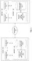
- FIG. 2is a more detailed illustration of the client-side and server-side design applications of FIG. 1 , according to various embodiments of the present invention.
- client-side design application 120 - 0includes, without limitations, a setup engine 200 , a problem specification 202 , an analysis engine 204 , design recommendations 206 , a client-side solver 208 , a solution approximation 210 , a graphical user interface (GUI) engine 212 , and a GUI 214 .
- server-side design application 120 - 1includes, without limitation, a server-side solver 258 .
- Setup engine 200is configured to generate problem specification 202 .
- Analysis engine 204is configured to generate design recommendations 206 .
- Client-side solver 208is a solution engine that is configured to generate solution approximation 210 .
- GUI engine 212is configured to generate GUI 214 .
- GUI 214may include graphical representations of problem specification 202 , design recommendations 206 , and/or solutions approximation 210 .
- An end-usermay interact with setup engine 200 , analysis engine 204 , client-side solver 208 and GUI engine 212 via GUI 214 .
- Setup engine 200provides various tools that allow the end-user to define a design problem to be solved within a simulated three-dimensional (3D) environment.
- the end-usermay interact with setup engine 200 , via GUI 214 , to define design problem geometry, design objectives, design constraints, boundary conditions, and other data associated with the design problem. This data may inform the process of creating solutions to the design problem. An example of this process is described below in conjunction with FIGS. 3-5 .
- setup engine 200Based on interactions with the end-user, setup engine 200 generates problem specification 202 .
- Problem specification 202is a data structure that embodies all of the design problem information received via interactions with the end-user.
- problem specification 202could reflect a 3D environment that includes specific locations where certain forces are to be supported, within precise volumetric constraints, under particular weight limitations.
- Analysis engine 204is configured to process problem specification 202 to determine whether the design problem outlined in that specification is sufficiently well defined to allow a multi-objective solver included in client-side solver 208 to generate design solutions for that design problem. For example, analysis engine 204 could analyze problem specification 202 to determine whether all portions of the design problem geometry are fully constrained. In another example, analysis engine 204 could analyze problem specification 202 to determine whether problem specification 204 includes a threshold number of design constraints.
- analysis engine 204executes a function that queries problem specification 202 periodically to test for a set of attributes needed prior to submission of that specification to server 150 for processing. In doing so, analysis engine 204 determines whether a threshold set of design constraints are met. Analysis engine 204 also determines whether a set of goals is met (e.g., loading criteria, fluid flow criteria, thermal criteria, geometric criteria, etc.). Analysis engine 204 queries problem specification 202 to determine whether sufficient constraints and goals are present. When problem specification 202 has been completed to the threshold level, the end-user is notified that the problem specification 202 is ready to be submitted to server 150 and the ability to generate and display approximate design solution 210 is enabled.
- a threshold set of design constraintse.g., loading criteria, fluid flow criteria, thermal criteria, geometric criteria, etc.
- analysis engine 204identifies the minimum input requirements of client-side solver 208 , and then determines whether problem specification 202 provides those minimum input requirements. If problem specification 202 does not include sufficient data, then analysis engine 204 generates design recommendations 206 and displays those recommendations via GUI engine 212 . Design recommendations 206 include suggested changes to problem specification 202 that, if applied, would cause problem specification 204 to reach the minimum input input requirements of client-side solver 208 . The end-user may accept those recommendations and/or continue editing problem specification 202 until analysis engine 204 identifies that the minimum input requirements have been met.
- client-side solver 208executes the multi-objective solver mentioned to generate a set of design solutions that potentially solve the design problem associated with problem specification 202 .
- Client-side solver 208generally implements a coarse solution strategy that favors speed over accuracy. Therefore, the various design solutions generated by client-side solver 208 may not optimally solve the design problem. However, the range of design solutions generated in this fashion may be used to illustrate to the end-user an approximation of a design solution that could be generated via a finer and more accurate solution strategy.
- client-side solver 208combines the set of design solutions generated via execution of the multi-objective solver in order to create solution approximation 210 .
- Solution approximation 210is a composite of two or more design solutions.
- GUI engine 212then renders solution approximation 210 within the 3D environment associated with problem specification 202 .
- An exemplary solution approximationis described below in conjunction with FIG. 6 .
- the end-usermay identify regions of the design geometry in need of modification, additional design constraints, further design objectives, and so forth. Then, the end-user may make any needed changes, as also described below in conjunction with FIG. 7 .
- Server-side solver 258is a solution engine configured to execute a multi-objective solver that implements a much finer and more accurate solution strategy than client-side solver 208 .
- Server-side solver 258may implement a similar multi-objective solver as client-side solver 208 , however, server-side solver 258 performs vastly more computationally intensive operations to generate design solutions compared to client-side solver 208 .
- client-side solver 208could execute a topology generation algorithm using 1000 grid cells, while server-side solver could execute a similar topology generation algorithm using 100,000,000 grid cells.
- client-side solver 208could execute a numerical simulation that performs only 10 iterations, while server-side solver could execute a similar numerical simulation that performs 1,000,000 iterations.
- server-side solver 258executes in a computational environment that offers computational resources that exceed those available to client-side solve 208 . Usage of those resources may require the end-user to expend capital. Accordingly, the end-user may wish to finalize problem specification 202 before submitting that problem specification to server-side solver 258 for processing, thereby avoiding the unnecessary expenditure of capital.
- client-side solver 208allows the end-user review solution approximation 210 , in advance of submitting problem specification 202 to server-side solver 258 , to identify omissions, correct mistakes, and so forth. This approach may make the design process more efficient and allow more robust problem specifications, with potentially fewer errors, to be submitted for processing.
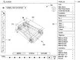
- FIG. 3illustrates design problem geometry that is generated via the setup engine of FIG. 2 , according to various embodiments of the present invention.
- GUI 214includes, without limitation, a design space 300 , a toolbar 310 , and a data panel 320 .
- Design space 300generally corresponds to problem specification 202 .
- Design space 300includes a 3D environment where an end-user generates design problem geometry 330 .
- Design problem geometry 330represents specific boundary conditions and/or bounding geometry associated with a design problem.
- Toolbar 310provides tools that the end-user may manipulate in order to generate design problem geometry 330 .
- Data panel 320includes information associated with design problem geometry 330 , including various geometrical and/or physical attributes of design problem geometry 330 .
- GUI engine 212receives end-user input, via one or more of the tools included in toolbar 310 , which describe design problem geometry 330 .
- setup engine 200updates problem specification 202 to reflect design space 300 .
- analysis engine 204analyzes problem specification 202 and provides a reference geometry that may assist the end-user with completing design problem geometry 330 , as described in greater detail below in conjunction with FIG. 4 .
- FIG. 4illustrates reference geometry generated via the analysis engine of FIG. 2 and associated with the design problem geometry of FIG. 3 , according to various embodiments of the present invention.
- design space 300includes, without limitation, reference geometry 400 that represents a skeleton of a potentially feasible design solution.
- Analysis engine 204is configured to analyze design space geometry 330 , as the geometry evolves based on end-user input, to determine potentially similar approaches to solving the design problem associated with that geometry.
- analysis engine 204could analyze the physical organization of boundary conditions associated with design space geometry 330 to identify (e.g., within a database) existing design solutions for similarly organized boundary conditions. Then, analysis engine 204 could generate reference geometry 400 based on those solutions, and adapt that geometry to fit within design space geometry 330 .
- reference geometry 400is “geometrically similar” to design problem geometry 330 .
- geometrically similar constructshave at least one point, at least one line segment, at least one junction between line segments, at least one arc, at least one surface, or at least one junction between surfaces in common with one another.
- Reference geometry 400provides sample locations where the end-user may apply design objectives and/or design constraints, including forces that should be balanced by feasible design solutions, as described in greater detail below in conjunction with FIG. 5 .
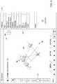
- FIG. 5illustrates a set of forces generated via the setup engine of FIG. 2 and associated with the design problem geometry of FIG. 3 , according to various embodiments of the present invention.
- GUI 214includes, without limitation, a set of forces 500 associated with design problem geometry 330 .
- the end-usermay define forces 500 via tools provided in toolbar 310 .
- Each force 500may represent a force applied to a specific location on design problem geometry 330 , a force applied to a specific location on reference geometry 400 , or a force applied to a location proximate to design problem geometry 330 .
- forces 500are to be balanced by a feasible design solution.
- forces 500represent one form of design objective.
- the end-usermay also add constraints to design geometry 330 via interactions with GUI 214 , including geometric constraints, physical constraints, manufacturing constraints, and so forth.
- setup engine 202updates problem specification 202 , as mentioned above.
- analysis engine 204analyzes design space 300 , design problem geometry 330 , and other data within that problem specification to determine whether sufficient information exists to generate at least a coarse design solution that roughly approximates a feasible design solution.
- analysis engine 204may identify the minimum input requirements of client-side solver 208 , and then determine whether problem specification 202 provides those minimum input requirements. When problem specification 202 includes sufficient information, client-side solver 208 executes the multi-objective solver to generate a set of design solutions, then combines those potentially solutions to generate solution approximation 210 , as described in greater detail below in conjunction with FIG. 6 .
- FIG. 6illustrates an approximate solution to the design problem generated via the client-side solver of FIG. 2 , according to various embodiments of the present invention.
- GUI 214includes, without limitation, solution approximation 210 enclosed by a bounding box 600 .
- Solution approximation 210represents a “fuzzy” version of a range of potentially feasible design solutions.
- Solution approximation 210may be generated based on a small collection of design solutions, generated using a solution strategy that favors speed over accuracy. Thus, solution approximation 210 may not fully meet all design objectives and/or design constraints. However, solution approximation 210 provides the end-user with a rough view of the topology of potential design solutions.
- solution approximation 210includes geometry in a region of design problem geometry 330 where other geometry needs to reside. The end-user may observe this issue and then take corrective action, as described in greater detail below in conjunction with FIG. 7 .
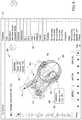
- FIG. 7illustrates additional constraints added to the approximate solution to the design problem via the setup engine of FIG. 2 , according to various embodiments of the present invention.
- GUI 214includes, without limitation, a wheel 700 , a shock mount 710 , and a chain 720 .
- These componentsrepresent additional geometry that needs to be added to design space 300 as design constraints to indicate that design solutions should not include geometry within the volumes of those components.
- the end-usermay add wheel 700 , shock mount 710 , and chain 720 in order to further constrain problem specification 202 .
- Analysis engine 204may then analyze problem specification 202 and update solution approximation 210 and provide details regarding that updated solution approximation, as described in greater detail below in conjunction with FIG. 8 .
- FIG. 8illustrates various data added to the approximate solution to the design problem via the analysis engine of FIG. 2 , according to various embodiments of the present invention.
- GUI 214includes, without limitation, constraint popup 800 and variability popup 810 .
- Constrain popup 800provides the end-user with various data related to the constraint associated with wheel 700 .
- Variability popup 810provides information that reflects variations across all design solutions associated with solution approximation 810 . This data could include process variation, volume variation, and material usage variation.
- server-side solver 258may initiate computation of design solutions via server-side solver 258 within server-side design application 120 - 1 .
- usage of server-side solver 258may require the end-user to expend capital.
- providing the end-user with solution approximation 210 in the manner discussed herein, thereby allowing the end-user to correct omissions, mistakes,may prevent the end-user from expending capital to generate design solutions based on a flawed problem specification 202 .
- FIGS. 3-8persons skilled in the art will understand that theses figures are provided for illustrative purposes only and not meant to be limiting. The basic techniques described thus far are described in generic fashion below in conjunction with FIG. 9 .
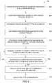
- FIG. 9is a flow diagram of method steps for generating an approximate solution to a design problem, according to various embodiments of the present invention. Although the method steps are described in conjunction with the systems of FIGS. 1-8 , persons skilled in the art will understand that any system configured to perform the method steps, in any order, is within the scope of the present invention.
- a method 900begins at step 902 , where setup engine 200 generates design problem geometry 330 in response to end-user interactions with GUI 214 .
- Design problem geometry 330represents specific boundary conditions and/or bounding geometry associated with a design problem.
- setup engine 200updates problem specification 202 to reflect design space 300 .
- analysis engine 204associates reference geometry 400 with design problem geometry 330 .
- analysis engine 204analyzes design space geometry 330 to determine potentially similar approaches to solving the design problem associated with that geometry. For example, analysis engine 204 could analyze the physical organization of boundary conditions associated with design space geometry 330 to identify (e.g., within a database) existing design solutions for similarly organized boundary conditions. Then, analysis engine 204 could generate reference geometry 400 based on those solutions, and adapt that geometry to fit within design space geometry 330 .
- setup engine 200determines a set of forces on design problem geometry 330 and/or reference geometry 400 .
- the end-usermay define the set of forces via tools provided in toolbar 310 .
- each force in the set of forcesis to be balanced by a feasible design solution.
- the set of forcesrepresents one form of design objective.
- setup engine 200determines design criteria associated with the design problem set forth in problem specification 202 .
- the end-usermay add design objectives, such as the set of forces described in conjunction with step 906 , add design constraints, include additional boundary conditions, and generally add any manner of design criteria in order to flesh out the design problem.
- setup engine 200synthesizes (or updates) problem specification 202 to include all such design criteria.
- analysis engine 204analyzes design space 300 , design problem geometry 330 , and other data within that problem specification to determine changes to design space 300 that would assist with completing design specification 202 .
- analysis engine 204may suggest to the end-user changes to design space 300 that would increase the level of completeness of problem specification 202 .
- analysis engine 204could suggest to the end-user that a specification geometrical constraint be removed so that the design problem is not overly constrained.
- analysis engine 204determines whether sufficient information exists within problem specification 202 to generate at least a coarse design solution that roughly approximates a feasible design solution. For example, analysis engine 204 could analyze problem specification 202 to determine whether all portions of the design problem geometry are fully constrained. More generally, analysis engine 204 identifies the minimum input requirements of client-side solver 208 , and then determines whether problem specification 202 provides those minimum input requirements. If problem specification 202 does not include sufficient information, then the method 900 returns to step 912 and proceeds as described above. Otherwise, the method 900 proceeds to step 916 .
- client-side solver 208generates solution approximation 210 .
- client-side solverexecutes the multi-objective solver mentioned previously to generate a set of design solutions that potentially solve the design problem associated with problem specification 202 .
- Client-side solver 208then generates a composite of those design problems to arrive at solution approximation 210 .
- solution approximation 210represents a “fuzzy” version of a range of potentially feasible design solutions.
- GUI engine 212updates GUI 214 to include solution approximation 210 .
- GUI engine 212may also populate GUI 214 with various data associated with solution approximation 210 , including constraint information as well as data that reflects variability across design solutions within solution approximation 210 .
- a design applicationinteracts with an end-user to generate design problem geometry that reflects a design problem to be solved.
- Various design objectives, design constraints, boundary conditions, and other design criteriamay be associated with the design problem geometry via the design application.
- a client-side solverWhen the design problem is sufficiently well defined, a client-side solver generates a solution approximation using a coarse multi-objective solver. The client-side solver favors speed over accuracy, and so the solution approximation provides only a rough representation of various attributes of potentially feasible design solutions. Based on the solution approximation, the end-user may correct any omissions, mistakes, and so forth, before executing pay-per-service cloud-based parallel solver.
- At least one advantage of the disclosed approachis that it allows an end-user to review and verify an approximate rendering of potential design solutions before causing a computationally intensive, and possibly expensive, rendering of design solutions to take place.
- the end-usermay avoid expending time and other resources until a design problem is fully specified and verified, thereby making the design process substantially more efficient.
- aspects of the present embodimentsmay be embodied as a system, method or computer program product. Accordingly, aspects of the present disclosure may take the form of an entirely hardware embodiment, an entirely software embodiment (including firmware, resident software, micro-code, etc.) or an embodiment combining software and hardware aspects that may all generally be referred to herein as a “circuit,” “module” or “system.” Furthermore, aspects of the present disclosure may take the form of a computer program product embodied in one or more computer readable medium(s) having computer readable program code embodied thereon.
- the computer readable mediummay be a computer readable signal medium or a computer readable storage medium.
- a computer readable storage mediummay be, for example, but not limited to, an electronic, magnetic, optical, electromagnetic, infrared, or semiconductor system, apparatus, or device, or any suitable combination of the foregoing.
- a computer readable storage mediummay be any tangible medium that can contain, or store a program for use by or in connection with an instruction execution system, apparatus, or device.
- each block in the flowchart or block diagramsmay represent a module, segment, or portion of code, which comprises one or more executable instructions for implementing the specified logical function(s).
- the functions noted in the blockmay occur out of the order noted in the figures. For example, two blocks shown in succession may, in fact, be executed substantially concurrently, or the blocks may sometimes be executed in the reverse order, depending upon the functionality involved.
Landscapes
- Engineering & Computer Science (AREA)
- Theoretical Computer Science (AREA)
- Physics & Mathematics (AREA)
- General Physics & Mathematics (AREA)
- General Engineering & Computer Science (AREA)
- Human Computer Interaction (AREA)
- Computer Hardware Design (AREA)
- Geometry (AREA)
- Evolutionary Computation (AREA)
- Computer Graphics (AREA)
- Manufacturing & Machinery (AREA)
- Automation & Control Theory (AREA)
- Data Mining & Analysis (AREA)
- Multimedia (AREA)
- Databases & Information Systems (AREA)
- Software Systems (AREA)
- Architecture (AREA)
- Management, Administration, Business Operations System, And Electronic Commerce (AREA)
- User Interface Of Digital Computer (AREA)
- Stored Programmes (AREA)
- Processing Or Creating Images (AREA)
Abstract
Description
Claims (23)
Priority Applications (1)
| Application Number | Priority Date | Filing Date | Title |
|---|---|---|---|
| US14/951,349US10867083B2 (en) | 2014-11-25 | 2015-11-24 | Technique for generating approximate design solutions |
Applications Claiming Priority (2)
| Application Number | Priority Date | Filing Date | Title |
|---|---|---|---|
| US201462084490P | 2014-11-25 | 2014-11-25 | |
| US14/951,349US10867083B2 (en) | 2014-11-25 | 2015-11-24 | Technique for generating approximate design solutions |
Publications (2)
| Publication Number | Publication Date |
|---|---|
| US20160147914A1 US20160147914A1 (en) | 2016-05-26 |
| US10867083B2true US10867083B2 (en) | 2020-12-15 |
Family
ID=56010114
Family Applications (6)
| Application Number | Title | Priority Date | Filing Date |
|---|---|---|---|
| US14/951,366Active2036-09-05US11003807B2 (en) | 2014-11-25 | 2015-11-24 | Techniques for generating materials to satisfy design criteria |
| US14/951,297Active2038-10-17US11113433B2 (en) | 2014-11-25 | 2015-11-24 | Technique for generating a spectrum of feasible design solutions |
| US14/951,327Active2037-07-07US10324453B2 (en) | 2014-11-25 | 2015-11-24 | Space for materials selection |
| US14/951,310Active2037-08-23US10803209B2 (en) | 2014-11-25 | 2015-11-24 | Tracking the evolution of a design space |
| US14/951,338Active2038-12-03US10775955B2 (en) | 2014-11-25 | 2015-11-24 | Approach for generating and exploring a design space |
| US14/951,349Active2039-03-28US10867083B2 (en) | 2014-11-25 | 2015-11-24 | Technique for generating approximate design solutions |
Family Applications Before (5)
| Application Number | Title | Priority Date | Filing Date |
|---|---|---|---|
| US14/951,366Active2036-09-05US11003807B2 (en) | 2014-11-25 | 2015-11-24 | Techniques for generating materials to satisfy design criteria |
| US14/951,297Active2038-10-17US11113433B2 (en) | 2014-11-25 | 2015-11-24 | Technique for generating a spectrum of feasible design solutions |
| US14/951,327Active2037-07-07US10324453B2 (en) | 2014-11-25 | 2015-11-24 | Space for materials selection |
| US14/951,310Active2037-08-23US10803209B2 (en) | 2014-11-25 | 2015-11-24 | Tracking the evolution of a design space |
| US14/951,338Active2038-12-03US10775955B2 (en) | 2014-11-25 | 2015-11-24 | Approach for generating and exploring a design space |
Country Status (1)
| Country | Link |
|---|---|
| US (6) | US11003807B2 (en) |
Families Citing this family (22)
| Publication number | Priority date | Publication date | Assignee | Title |
|---|---|---|---|---|
| US20160092041A1 (en)* | 2014-09-29 | 2016-03-31 | Madesolid, Inc. | System and method to facilitate material selection for a three dimensional printing object |
| US10068100B2 (en)* | 2016-01-20 | 2018-09-04 | Microsoft Technology Licensing, Llc | Painting content classifications onto document portions |
| WO2017161250A1 (en)* | 2016-03-17 | 2017-09-21 | Elsevier, Inc. | Systems and methods for electronic searching of materials and material properties |
| US9972140B1 (en) | 2016-11-15 | 2018-05-15 | Southern Graphics Inc. | Consumer product advertising image generation system and method |
| JP6579123B2 (en)* | 2017-02-13 | 2019-09-25 | 横河電機株式会社 | Engineering apparatus, engineering method and program |
| WO2018187291A2 (en)* | 2017-04-04 | 2018-10-11 | ParaMatters Inc. | Cognitive system for computer aided design |
| EP4002284B1 (en)* | 2017-10-13 | 2023-04-12 | Dassault Systèmes | Method for creating an animation summarizing a design process of a three-dimensional object |
| US11250180B2 (en)* | 2017-11-27 | 2022-02-15 | Autodesk, Inc. | Adaptive transformable design generation |
| US10909288B2 (en) | 2017-12-26 | 2021-02-02 | Autodesk, Inc. | Techniques for applying generative design to the configuration of mechanical assemblies |
| US10885236B2 (en)* | 2018-01-09 | 2021-01-05 | Autodesk, Inc. | Constraint-oriented programming approach to mechanical assembly design |
| US20190325086A1 (en)* | 2018-04-23 | 2019-10-24 | Autodesk, Inc. | Techniques for visualizing and exploring large-scale generative design datasets |
| US11475178B2 (en)* | 2018-05-08 | 2022-10-18 | Autodesk, Inc. | Generative design techniques for automobile designs |
| US10796266B2 (en)* | 2018-05-08 | 2020-10-06 | The Boeing Company | Automated context driven build plan lifecycle |
| US11727166B2 (en) | 2018-05-08 | 2023-08-15 | Autodesk, Inc. | Techniques for generating graph-based representations of complex mechanical assemblies |
| US11409756B1 (en)* | 2018-09-29 | 2022-08-09 | Splunk Inc. | Creating and communicating data analyses using data visualization pipelines |
| US20200272703A1 (en)* | 2019-02-25 | 2020-08-27 | Citrine Informatics, Inc. | Predictive design space metrics for materials development |
| US11068135B2 (en) | 2019-04-22 | 2021-07-20 | Autodesk, Inc. | Techniques for visualizing probabilistic data generated when designing mechanical assemblies |
| US11288417B2 (en)* | 2019-04-23 | 2022-03-29 | Autodesk, Inc. | Topology optimization of structure with multiple targets |
| US11628625B2 (en)* | 2020-01-27 | 2023-04-18 | State Farm Mutual Automobile Insurance Company | System and method for custom material, replacement |
| US11727173B2 (en) | 2020-12-16 | 2023-08-15 | Lendlease Digital IP Pty Limited | System and method for automatically generating an optimized building floor plate layout |
| CN113848803B (en)* | 2021-10-14 | 2023-09-12 | 成都永峰科技有限公司 | Deep cavity curved surface machining tool path generation method |
| US20230315947A1 (en)* | 2022-04-05 | 2023-10-05 | Tencent America LLC | Structural design using finite-element analysis |
Citations (25)
| Publication number | Priority date | Publication date | Assignee | Title |
|---|---|---|---|---|
| JPH0581355A (en) | 1991-09-21 | 1993-04-02 | Nissan Motor Co Ltd | Design procedure supporting device |
| US5510995A (en)* | 1993-08-13 | 1996-04-23 | Iowa State University Research Foundation, Inc. | Sculptured surface synthesis based on functional design constraints |
| US20030210241A1 (en) | 2002-05-07 | 2003-11-13 | Shunsuke Minami | CAD data evaluation method and evaluation apparatus |
| US20050038821A1 (en) | 2001-05-15 | 2005-02-17 | Wallen Todd Alan | Method and system for capturing, managing and disseminating manufacturing knowledge |
| US20060058985A1 (en)* | 2004-08-31 | 2006-03-16 | Supersonic Aerospace International, Llc | Adjoint-based design variable adaptation |
| US20060066609A1 (en) | 2004-09-28 | 2006-03-30 | Iodice Arthur P | Methods and systems for viewing geometry of an object model generated by a CAD tool |
| US20070078634A1 (en) | 2005-09-30 | 2007-04-05 | Anandasivam Krishnapillai | Method and system for automated design |
| US20070118243A1 (en) | 2005-10-14 | 2007-05-24 | Vantus Technology Corporation | Personal fit medical implants and orthopedic surgical instruments and methods for making |
| CN101038599A (en) | 2006-03-16 | 2007-09-19 | 刘守奎 | Method for displaying name and distance of building axis line on computer screen |
| US20080222110A1 (en)* | 2007-03-07 | 2008-09-11 | Fujitsu Limited | Design method and recording medium |
| US20080319928A1 (en)* | 2007-06-19 | 2008-12-25 | Ono Sokki Co. Ltd. | Method, computer, and recording medium storing a program for computing an optimal solution to engine design variables |
| US20090306801A1 (en) | 2006-11-27 | 2009-12-10 | Northeastern University | Patient specific ankle-foot orthotic device |
| US20100057652A1 (en)* | 2008-08-29 | 2010-03-04 | Fifth Generation Technologies India Ltd | Approach for solving global optimization problem |
| US8392160B2 (en) | 2009-05-15 | 2013-03-05 | Autodesk, Inc. | Energy usage in injection molding simulations |
| US20130170171A1 (en) | 2012-01-04 | 2013-07-04 | Board Of Regents, The University Of Texas System | Extrusion-based additive manufacturing system for 3d structural electronic, electromagnetic and electromechanical components/devices |
| US20130233618A1 (en) | 2010-11-19 | 2013-09-12 | Murata Manufacturing Co., Ltd. | Conductive material, bonding method using the same, and bonded structure |
| US8589125B2 (en) | 2007-10-04 | 2013-11-19 | Ihi Corporation | Product design support system and method for simulating a prototype of a design object |
| US8666702B2 (en) | 2007-02-07 | 2014-03-04 | SEW Eurodrive GmbH & Co. KG | Method and apparatus for generating design drawings |
| US20140108953A1 (en) | 2012-10-15 | 2014-04-17 | 3Form | Systems and methods for selecting colored films and designing layouts |
| US8818769B2 (en)* | 2010-10-28 | 2014-08-26 | Parametric Technology Corporation | Methods and systems for managing synchronization of a plurality of information items of a computer-aided design data model |
| US20150099059A1 (en) | 2012-12-27 | 2015-04-09 | Kateeva, Inc. | Techniques for Print Ink Droplet Measurement and Control to Deposit Fluids within Precise Tolerances |
| US20150324489A1 (en)* | 2012-09-06 | 2015-11-12 | Hitachi, Ltd. | Design change process management device and method |
| US20150356207A1 (en) | 2014-06-06 | 2015-12-10 | Ptc Inc. | Methods and system for incremental exploration of design changes in large computer-aided design models |
| US20150362898A1 (en)* | 2013-01-17 | 2015-12-17 | Bae Systems | Object production using an additive manufacturing process |
| US9785727B1 (en) | 2014-01-10 | 2017-10-10 | Verso Furniture, Inc. | Method and system of assembly design |
Family Cites Families (6)
| Publication number | Priority date | Publication date | Assignee | Title |
|---|---|---|---|---|
| US20050081354A1 (en)* | 2003-10-16 | 2005-04-21 | Hydrill, Inc. | Method and apparatus for rivet removal and in-situ rehabilitation of large metal structures |
| US7801710B2 (en)* | 2007-09-28 | 2010-09-21 | Rockwell Automation Technologies, Inc. | Simulation controls for model variability and randomness |
| GB0818308D0 (en)* | 2008-10-07 | 2008-11-12 | Helic S A | Expert system-based integrated inductor synthesis and optimization |
| US9364896B2 (en)* | 2012-02-07 | 2016-06-14 | Medical Modeling Inc. | Fabrication of hybrid solid-porous medical implantable devices with electron beam melting technology |
| US9690880B2 (en)* | 2012-11-27 | 2017-06-27 | Autodesk, Inc. | Goal-driven computer aided design workflow |
| EP2954439A4 (en)* | 2013-02-08 | 2016-12-07 | Eko Futura Näringslivsutveckling Ab | Method and device for handling data containers |
- 2015
- 2015-11-24USUS14/951,366patent/US11003807B2/enactiveActive
- 2015-11-24USUS14/951,297patent/US11113433B2/enactiveActive
- 2015-11-24USUS14/951,327patent/US10324453B2/enactiveActive
- 2015-11-24USUS14/951,310patent/US10803209B2/enactiveActive
- 2015-11-24USUS14/951,338patent/US10775955B2/enactiveActive
- 2015-11-24USUS14/951,349patent/US10867083B2/enactiveActive
Patent Citations (25)
| Publication number | Priority date | Publication date | Assignee | Title |
|---|---|---|---|---|
| JPH0581355A (en) | 1991-09-21 | 1993-04-02 | Nissan Motor Co Ltd | Design procedure supporting device |
| US5510995A (en)* | 1993-08-13 | 1996-04-23 | Iowa State University Research Foundation, Inc. | Sculptured surface synthesis based on functional design constraints |
| US20050038821A1 (en) | 2001-05-15 | 2005-02-17 | Wallen Todd Alan | Method and system for capturing, managing and disseminating manufacturing knowledge |
| US20030210241A1 (en) | 2002-05-07 | 2003-11-13 | Shunsuke Minami | CAD data evaluation method and evaluation apparatus |
| US20060058985A1 (en)* | 2004-08-31 | 2006-03-16 | Supersonic Aerospace International, Llc | Adjoint-based design variable adaptation |
| US20060066609A1 (en) | 2004-09-28 | 2006-03-30 | Iodice Arthur P | Methods and systems for viewing geometry of an object model generated by a CAD tool |
| US20070078634A1 (en) | 2005-09-30 | 2007-04-05 | Anandasivam Krishnapillai | Method and system for automated design |
| US20070118243A1 (en) | 2005-10-14 | 2007-05-24 | Vantus Technology Corporation | Personal fit medical implants and orthopedic surgical instruments and methods for making |
| CN101038599A (en) | 2006-03-16 | 2007-09-19 | 刘守奎 | Method for displaying name and distance of building axis line on computer screen |
| US20090306801A1 (en) | 2006-11-27 | 2009-12-10 | Northeastern University | Patient specific ankle-foot orthotic device |
| US8666702B2 (en) | 2007-02-07 | 2014-03-04 | SEW Eurodrive GmbH & Co. KG | Method and apparatus for generating design drawings |
| US20080222110A1 (en)* | 2007-03-07 | 2008-09-11 | Fujitsu Limited | Design method and recording medium |
| US20080319928A1 (en)* | 2007-06-19 | 2008-12-25 | Ono Sokki Co. Ltd. | Method, computer, and recording medium storing a program for computing an optimal solution to engine design variables |
| US8589125B2 (en) | 2007-10-04 | 2013-11-19 | Ihi Corporation | Product design support system and method for simulating a prototype of a design object |
| US20100057652A1 (en)* | 2008-08-29 | 2010-03-04 | Fifth Generation Technologies India Ltd | Approach for solving global optimization problem |
| US8392160B2 (en) | 2009-05-15 | 2013-03-05 | Autodesk, Inc. | Energy usage in injection molding simulations |
| US8818769B2 (en)* | 2010-10-28 | 2014-08-26 | Parametric Technology Corporation | Methods and systems for managing synchronization of a plurality of information items of a computer-aided design data model |
| US20130233618A1 (en) | 2010-11-19 | 2013-09-12 | Murata Manufacturing Co., Ltd. | Conductive material, bonding method using the same, and bonded structure |
| US20130170171A1 (en) | 2012-01-04 | 2013-07-04 | Board Of Regents, The University Of Texas System | Extrusion-based additive manufacturing system for 3d structural electronic, electromagnetic and electromechanical components/devices |
| US20150324489A1 (en)* | 2012-09-06 | 2015-11-12 | Hitachi, Ltd. | Design change process management device and method |
| US20140108953A1 (en) | 2012-10-15 | 2014-04-17 | 3Form | Systems and methods for selecting colored films and designing layouts |
| US20150099059A1 (en) | 2012-12-27 | 2015-04-09 | Kateeva, Inc. | Techniques for Print Ink Droplet Measurement and Control to Deposit Fluids within Precise Tolerances |
| US20150362898A1 (en)* | 2013-01-17 | 2015-12-17 | Bae Systems | Object production using an additive manufacturing process |
| US9785727B1 (en) | 2014-01-10 | 2017-10-10 | Verso Furniture, Inc. | Method and system of assembly design |
| US20150356207A1 (en) | 2014-06-06 | 2015-12-10 | Ptc Inc. | Methods and system for incremental exploration of design changes in large computer-aided design models |
Non-Patent Citations (33)
| Title |
|---|
| Arieff, A. 2013. New Forms that Function Better. MIT Technology Review http://www.technologyreview.com/review/517596/new-formsthat-function-better/ pp. 1-10. |
| Bertini, E., Dell'Aquila, L., & Santucci, G. 2005. "SpringView: cooperation of radviz and parallel coordinates for view optimization and clutter reduction". In Coordinated and Multiple Views in Exploratory Visualization. (8 pages). |
| Draper, G., Livnat, Y., & Riesenfeld, R. F. 2009. "A survey of radial methods for information visualization". In Visualization and Computer Graphics. pp. 1-45. |
| Dunne, C. and Shneiderman, B. 2013. "Motif simplification: improving network visualization readability with fan, connector, and clique glyphs". In Proc CHI '13 (14 pages). |
| Final Office Action received for U.S. Appl. No. 14/951,297, dated Apr. 22, 2020, 17 pages. |
| Final Office Action received in U.S. Appl. No. 14/951,310, dated Dec. 12, 2019, 39 pages. |
| Flager F, Welle B, Bansal P, Soremekun G, Haymaker J. 2009. "Multidisciplinary process integration and design optimization of a classroom building". Journal of Information Technology in Construction, vol. 14. 595-612. |
| Flager, F. and Haymaker, J. 2007. "A Comparison of Multidisciplinary Design, Analysis and Optimization Processes in the Building Construction and Aerospace Industries". In Proc. of the 24th International Conference on Information Technology in Construction. pp. 1-12. |
| Gerber, D. J., Lin, S.-H., Pan, B. and Solmaz, A. S. 2012. "Design optioneering: multi-disciplinary design optimization through parameterization, domain integration and automation of a genetic algorithm". In Proc. Symposium on Simulation for Architecture and Urban Design, Society for Computer Simulation International. (pp. 23-30). |
| Graham, M., & Kennedy, J. 2003. "Using curves to enhance parallel coordinate visualisations". In Information Visualization, 2003. |
| Grossman, T., Matejka, T. and Fitzmaurice, G. 2010. "Chronicle: capture, exploration, and playback of document workflow histories". In Proc UIST '10. (pp. 143-152). |
| Hauser, H., Ledermann, F., & Doleisch, H. 2002. "Angular brushing of extended parallel coordinates". In Information Visualization, 2002. (4 pages). |
| Holzer, D., Hough, R. and Burry, M. 2007. "Parametric Design and Structural Optimisation for Early Design Exploration". International, Journal of Architectural Computing, vol. 5, 4. 625-643. |
| Lunzer, A. and Hornbæk, K. 2008. "Subjunctive interfaces: Extending applications to support parallel setup, viewing and control of alternative scenarios". ACM Transactions on Computer-Human Interaction vol. 14, 4. 1-17. |
| Maile, T., Fischer, M., Bazjanac, V. 2007. "Building energy performance simulation tools-a life-cycle and interoperable perspective". Working Paper. Center for Integrated Facility Engineering, Stanford University. (47 pages). |
| Maile, T., Fischer, M., Bazjanac, V. 2007. "Building energy performance simulation tools—a life-cycle and interoperable perspective". Working Paper. Center for Integrated Facility Engineering, Stanford University. (47 pages). |
| Marks, J., Andalman, B., Beardsley, P. A., Freeman, W., Gibson, S., Hodgins, J., . . . & Shieber, S. 1997. "Design galleries: A general approach to setting parameters for computer graphics and animation". In Proc. of the 24th annual conference on Computer graphics and interactive techniques. |
| Non-final Office Action for U.S. Appl. No. 14/951,310 dated Jun. 7, 2018, 21 pages. |
| Non-Final Office Action received in U.S. Appl. No. 14/951,297, dated Dec. 9, 2019, 30 pages. |
| Non-Final Office Action received in U.S. Appl. No. 14/951,338, dated Dec. 11, 2019, 32 pages. |
| Non-Final Office Action received in U.S. Appl. No. 14/951,366, dated Nov. 12, 2019, 23 pages. |
| Shah, J., Vergas-Hernandez, N., Smith, S. 2003. "Metrics for measuring ideation effectiveness". Design Studies vol. 24. 111-134. |
| Shneiderman, B. 1996. "The eyes have it: A task by data type taxonomy for information visualizations". In Proc. of IEEE Symposium on Visual Languages. (pp. 336-343). |
| Shneiderman, B., Hewett, T., Fischer, G., Jennings, P. 2006. et al. "Creativity Support Tools: Report from a US National Science Foundation Sponsored Workshop". International Journal of Human Computer Interaction, 20, 2. 61-77. |
| Steed, C. A., Fitzpatrick, P. J., Jankun-Kelly, T. J., Yancey, A. N., & Swan II, J. E. 2009. "An interactive parallel coordinates technique applied to a tropical cyclone climate analysis". Computers & Geosciences. (pp. 1-40). |
| Strauss, A. and Corbin, J. 1998. "Basics of qualitative research: Techniques and procedures for developing grounded theory". Thousand Oaks, CA: Sage. (133 pages). |
| Terry, M., Mynatt, E.D., Nakakoji, K., and Yamamoto, Y. 2004. "Variation in element and action: supporting simultaneous development of alternative solutions". In Proc CHI '04 (pp. 711-718). |
| Thibodeau, T. 2013. "U.S. makes a Top 10 supercomputer available to anyone who can 'boost' America". In www.computerworld.com. |
| Thibodeau, T. 2013. "U.S. makes a Top 10 supercomputer available to anyone who can ‘boost’ America". In www.computerworld.com. |
| Ward, M. O. 1994. "Xmdvtool: Integrating multiple methods for visualizing multivariate data". In Proc. of the Conference on Visulization. (9 pages). |
| Ward, M. O. 2002. "A taxonomy of glyph placement strategies for multidimensional data visualization". Information Visualization. (pp. 194-210). |
| Wegman, E. J. 1990. "Hyperdimensional data analysis using parallel coordinates". Journal of the American Statistical Association. (pp. 664-675). |
| Wong, P. C., & Bergeron, R. D. 1994. "30 Years of Multidimensional Multivariate Visualization". In Scientific Visualization. (pp. 1-30). |
Also Published As
| Publication number | Publication date |
|---|---|
| US11113433B2 (en) | 2021-09-07 |
| US10803209B2 (en) | 2020-10-13 |
| US10324453B2 (en) | 2019-06-18 |
| US10775955B2 (en) | 2020-09-15 |
| US20160147217A1 (en) | 2016-05-26 |
| US11003807B2 (en) | 2021-05-11 |
| US20160147912A1 (en) | 2016-05-26 |
| US20160147911A1 (en) | 2016-05-26 |
| US20160147914A1 (en) | 2016-05-26 |
| US20160147913A1 (en) | 2016-05-26 |
| US20160147430A1 (en) | 2016-05-26 |
Similar Documents
| Publication | Publication Date | Title |
|---|---|---|
| US10867083B2 (en) | Technique for generating approximate design solutions | |
| US10489533B2 (en) | Techniques for warm starting finite element analyses with deep neural networks | |
| US10706205B2 (en) | Detecting hotspots in physical design layout patterns utilizing hotspot detection model with data augmentation | |
| US8204714B2 (en) | Method and computer program product for finding statistical bounds, corresponding parameter corners, and a probability density function of a performance target for a circuit | |
| US11886776B2 (en) | Techniques for generating graph-based representations of complex mechanical assemblies | |
| US12135919B2 (en) | Goal-driven computer aided design workflow | |
| CN108027809B (en) | Functional Correlation of Deep Learning-Based Volume Design | |
| CN107316082A (en) | Method and system for determining feature importance of machine learning samples | |
| CN113792155A (en) | Text verification method and device based on knowledge graph, electronic equipment and medium | |
| US10860767B1 (en) | Systems and methods for transient simulation of circuits with mutual inductors | |
| CN109074415A (en) | System and method for material constitutive modeling | |
| US11030362B2 (en) | Modeling and cooperative simulation of systems with interdependent discrete and continuous elements | |
| CN113361719A (en) | Incremental learning method based on image processing model and image processing method | |
| US20150339409A1 (en) | Mid-surface extraction for finite element analysis | |
| US20190347080A1 (en) | Branch objects for dependent optimization problems | |
| WO2020057104A1 (en) | Method and device for application development | |
| US11763046B2 (en) | Techniques for automatically selecting simulation tools for and performing related simulations on computer-generated designs | |
| CN114549941B (en) | Model testing method and device and electronic equipment | |
| US20250148169A1 (en) | Mirror Finite Element Mesh Generation | |
| EP4550195A1 (en) | Finite element mesh generation by mirroring | |
| EP4530963A1 (en) | System and method for optimizing carbon footprint associated with software applications | |
| US20230142773A1 (en) | Method and system for real-time simulations using convergence stopping criterion | |
| CN118551597A (en) | Acceleration correlation curve generation method, device, equipment, medium and vehicle | |
| KR20250097756A (en) | Method, device, chip, equipment and medium for floating point conversion | |
| CN115983076A (en) | Modelica system reduced model generation method, device, equipment and medium |
Legal Events
| Date | Code | Title | Description |
|---|---|---|---|
| AS | Assignment | Owner name:AUTODESK, INC., CALIFORNIA Free format text:ASSIGNMENT OF ASSIGNORS INTEREST;ASSIGNORS:BERGIN, MICHAEL;DAVIS, MARK;REEL/FRAME:037136/0587 Effective date:20151124 | |
| STPP | Information on status: patent application and granting procedure in general | Free format text:DOCKETED NEW CASE - READY FOR EXAMINATION | |
| STPP | Information on status: patent application and granting procedure in general | Free format text:NON FINAL ACTION MAILED | |
| STPP | Information on status: patent application and granting procedure in general | Free format text:RESPONSE TO NON-FINAL OFFICE ACTION ENTERED AND FORWARDED TO EXAMINER | |
| STPP | Information on status: patent application and granting procedure in general | Free format text:FINAL REJECTION MAILED | |
| STPP | Information on status: patent application and granting procedure in general | Free format text:DOCKETED NEW CASE - READY FOR EXAMINATION | |
| STPP | Information on status: patent application and granting procedure in general | Free format text:NON FINAL ACTION MAILED | |
| STPP | Information on status: patent application and granting procedure in general | Free format text:RESPONSE TO NON-FINAL OFFICE ACTION ENTERED AND FORWARDED TO EXAMINER | |
| STPP | Information on status: patent application and granting procedure in general | Free format text:PUBLICATIONS -- ISSUE FEE PAYMENT VERIFIED | |
| STCF | Information on status: patent grant | Free format text:PATENTED CASE | |
| MAFP | Maintenance fee payment | Free format text:PAYMENT OF MAINTENANCE FEE, 4TH YEAR, LARGE ENTITY (ORIGINAL EVENT CODE: M1551); ENTITY STATUS OF PATENT OWNER: LARGE ENTITY Year of fee payment:4 |