US10866379B2 - Flexible cable guide - Google Patents
Flexible cable guideDownload PDFInfo
- Publication number
- US10866379B2 US10866379B2US16/546,492US201916546492AUS10866379B2US 10866379 B2US10866379 B2US 10866379B2US 201916546492 AUS201916546492 AUS 201916546492AUS 10866379 B2US10866379 B2US 10866379B2
- Authority
- US
- United States
- Prior art keywords
- tray
- cable
- enclosure
- flexible
- side band
- Prior art date
- Legal status (The legal status is an assumption and is not a legal conclusion. Google has not performed a legal analysis and makes no representation as to the accuracy of the status listed.)
- Active
Links
Images


Classifications
- G—PHYSICS
- G02—OPTICS
- G02B—OPTICAL ELEMENTS, SYSTEMS OR APPARATUS
- G02B6/00—Light guides; Structural details of arrangements comprising light guides and other optical elements, e.g. couplings
- G02B6/44—Mechanical structures for providing tensile strength and external protection for fibres, e.g. optical transmission cables
- G02B6/4439—Auxiliary devices
- G02B6/444—Systems or boxes with surplus lengths
- G02B6/4452—Distribution frames
- G02B6/44526—Panels or rackmounts covering a whole width of the frame or rack
- G—PHYSICS
- G02—OPTICS
- G02B—OPTICAL ELEMENTS, SYSTEMS OR APPARATUS
- G02B6/00—Light guides; Structural details of arrangements comprising light guides and other optical elements, e.g. couplings
- G02B6/44—Mechanical structures for providing tensile strength and external protection for fibres, e.g. optical transmission cables
- G02B6/4439—Auxiliary devices
- G02B6/444—Systems or boxes with surplus lengths
- G02B6/4453—Cassettes
Definitions
- the present inventionrelates to a flexible cable guide.
- the present inventionrelates to a system and cable guide that guide fibre optic cables from outside an enclosure to a device mounted on a moveable tray within the enclosure.
- One drawback of such designsis that fiber optic cables entering the front of the enclosure become snagged on the trays which can lead to them being damaged or broken, or hindering the movement of the tray.
- a fiber optic cross connect systemfor interconnecting a first external equipment with a second external equipment.
- the systemcomprises an enclosure comprising a top, a bottom, a first side and a second side defining a tray receiving space therebetween, a slideable tray arranged horizontally and moveable between a stored position wherein the tray is within the tray receiving space and an extended position wherein the tray is substantially in front of the tray receiving space, an elongate fiber optic terminating equipment arranged on the tray for movement therewith and comprising a first interface arranged along a rearward edge and a second interface arranged along a forward edge, a first plurality of fiber optic cables each comprising a first end terminated at the first interface and a second end for termination at the first external equipment, a second plurality of fiber optic cables each comprising a first end terminated at the second interface and a second end for termination at the second external equipment, a flexible cable guide for guiding the first plurality of fiber optic cables and comprising a first
- a flexible cable guidefor guiding a plurality of fiber optic cables from outside of an enclosure, the enclosure comprising a top, a bottom, a first side and a second side defining a tray receiving space therebetween, to inside the enclosure for termination at a network equipment on a tray, the tray slideable horizontally between a stored position wherein the tray is within the tray receiving space and an extended position wherein the tray is substantially in front of the tray receiving space.
- the guidecomprises a first end for attachment to an outside of the first side of the enclosure and defining an entrance, a second end for attachment to the tray adjacent the first side, and an intermediate section between the first end and the second end comprising a plurality of spaced cable retainers interconnected by an elongate flexible side band, each of the cable retainers defining a cable passage wherein the plurality of cable passages together define a cable passageway arranged along the side band.
- FIG. 1provides a raised right front perspective view of a fiber optic cross connect system comprising a flexible cable guide in accordance with an illustrative embodiment of the present invention
- FIG. 2Aprovides a raised right front perspective view of a tray of fiber optic cross connect system comprising a flexible cable guide in a stored position and in accordance with an illustrative embodiment of the present invention
- FIG. 2Bprovides a raised right front perspective view of a tray of fiber optic cross connect system comprising a flexible cable guide in an extended position and in accordance with an illustrative embodiment of the present invention
- FIG. 3Aprovides a raised right front perspective view of a flexible cable guide in accordance with an illustrative embodiment of the present invention
- FIG. 3Bprovides a raised left perspective view of an end of a flexible cable guide and mounting plates in accordance with an illustrative embodiment of the present invention
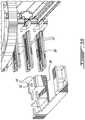
- FIG. 4provides a partial raised left front perspective sectional view of a fiber optic cross connect system comprising a flexible cable guide in accordance with an alternative illustrative embodiment of the present invention.
- FIG. 5provides a raised right front perspective view of a flexible cable guide in accordance with an alternative illustrative embodiment of the present invention.
- the flexible cable guide 10is illustratively foreseen for use in a cross connect system 12 .
- the cross connect system 12illustratively comprises an enclosure 14 dimensioned for mounting on a 19 ′′ rack 16 or the like.
- the enclosure 14comprises a top, bottom, first side and second side and defines a tray receiving space which houses one or more trays 18 which are arranged horizontally and slideably mounted and moveable between a stored position where the tray 18 is within the enclosure 14 and an extended position where the tray 18 is positioned in front of the enclosure 14 and accessible, for example by a technician or the like.
- elongate fiber optic terminating equipment 20such as fiber optic cassettes are illustratively arranged on the tray 18 for movement therewith.
- the terminating equipment 20comprises a first interface terminating one or more of a first plurality of fiber optic cables 22 and a second interface for terminating one or more of a second plurality of fiber optic cables 24 and illustratively such that the first plurality of fiber optic cables 22 and the second plurality of fiber optic cables 24 are interconnected.
- Such cassettes 20are removably mounted in trays 18 for example through the provision of tabs 26 which engage with tab receiving mounts 28 in the tray 18 .
- each of the trays 18is moveable on runners 30 , which run in complementary channels 32 attached to an inner surface of the enclosure 14 , between a stored position ( FIG. 2A ) and an extended position ( FIG. 2B ).
- a lever 34is provided to release a latch (not shown) which holds the tray 18 in the stored position.
- the first plurality of fiber optic cables 22are held in a cable way 36 which provides side access to the rear 38 of the tray 18 .
- the flexible cable guide 10is placed in the cable way 36 and removably secured at a first end 40 to an outside of the enclosure 14 and at a second end 42 to the tray 18 for movement therewith.
- the flexible cable guide 10is illustratively manufactured in one piece from a pliable material such as a flexible plastic or rubber or the like.
- the flexible cable guide 10comprises an elongate ribbon-like side band 44 which illustratively comprises a series of transverse notches 46 spaced regularly along a length thereof, thereby improving flexibility.
- a plurality of cable retainers 48are spaced along the side band 44 .
- the retainers 48each comprise a recloseable cover 50 allowing one or more fiber optic cables 22 to be secured using the cable guide 10 , or removed.
- a divider 52is provided separating each retainer 48 into two (2) cable passages 54 when closed.
- the first end 40 and the second end 42each comprise a plurality of flexible fingers 56 which serve to retain the cables 22 within the cable guide 10 while allowing them to be removed as necessary.
- the retainers 48 and their respective cable passages 54define a cable passageway arranged generally along the side band 44 .
- the first end 40 of the cable guide 10is secured to the outside of the enclosure 14 at a point proximate to where the first plurality of fiber optic cables 22 will enter the enclosure 14 .
- the second end 42is secured to the tray 18 for movement therewith.
- An intermediate portion of the cable guide 10is flexible and curved and such that the side band 44 delimits an outside of the curve.
- first plurality of fiber optic cables 22In this manner movement of the first plurality of fiber optic cables 22 is limited and such that they are not subject to excess strain and the like. Additionally, the first plurality of fiber optic cables 22 of one tray 18 are prevented from fouling or otherwise impeding the movement of the other trays 18 .
- the tray 18is first placed in the extended position and the covers 50 opened.
- One or more fiber optic cables 22are placed within selected one of the passages 54 and interconnected with respective ones of the cassettes 20 .
- the covers 50may then be closed the tray 18 placed in stored position of FIG. 2A . If fiber optic cables 22 must be removed or additional cables 22 added, the tray 18 is simply placed again in the extended position and the covers 50 opened.
- a plurality of horizontally extending mounting plates 52are provided.
- the mounting plates 52are arranged in vertical alignment and equally spaced such that the first ends 40 of each of the flexible cable guides 10 may be slid horizontally between successive ones of the mounting plates 52 .
- the ends 40are retained in place through the combination of pairs of opposed raised guides 54 and pairs of flexible bosses 56 which are held within channels 58 moulded or otherwise formed within the mounting plate 52 . In this manner the first end 40 can be released and re-secured such that additional optical fibers (not shown) can be mounted within the cable guide 10 .
- the covers 50 which provide access to the cable retainers 48are removeable and fabricated from a relatively rigid material such as plastic or the like.
- Each cover 50is secured to its respective cable retainers 48 at a proximate end via a hinge assembly 60 comprising a pair of clips 62 which receive a shaft 64 and about which the cover 50 can rotate.
- Each cover 50can be opened thereby allowing one or more fiber optic cables 22 to be retained by or removed from the cable guide 10 .
- Each cover 50may be subsequently be closed and retained in place by a tab 66 formed on an inside of a distal end 68 of each cover 50 and which engages a respective one of a plurality of tab receiving cut outs 70 moulded in the side band 44 .
- a bevelled surface 72is provided adjacent each cut out 70 to ease closing.
- a middle portion of each cover 50is stabilised by a boss 74 which engages a slot 76 in the cover 50 .
- Covers 50 of different trays 18can be colour coded to improve cable management and the like.
- the cable guide 10further comprises a pull tab 78 at the first end 40 to aid in removing the first end 40 from between the mounting plates 52 .
- a pull tab 78at the first end 40 to aid in removing the first end 40 from between the mounting plates 52 .
- an upper guide 80 and a lower guide 82are provided which engage an outer edge 88 of respectively an upper mounting plate 52 and a lower mounting plate 52 .
- the first end 40is held between the mounting plates 52 by a flexible clip 90 which engages a cut out 92 in an upper one of the mounting plates 52 .
- a plurality of flexible fingers 94are provided at both ends of the cable guide 10 to removeable retain the one or more fiber optic cables 22 there between.
- the second end 42comprises a flange 96 comprising a conical aperture 98 for receiving a screw 100 or the like for securing the second 42 to the tray 18 .
- the screw 100works together with a ridge 102 which engages an aperture (not shown) in the tray 18 in order to retain the second end 42 securely for movement with the tray 18 .
Landscapes
- Physics & Mathematics (AREA)
- General Physics & Mathematics (AREA)
- Optics & Photonics (AREA)
- Details Of Indoor Wiring (AREA)
- Light Guides In General And Applications Therefor (AREA)
Abstract
Description
Claims (20)
Priority Applications (3)
| Application Number | Priority Date | Filing Date | Title |
|---|---|---|---|
| US16/546,492US10866379B2 (en) | 2018-08-24 | 2019-08-21 | Flexible cable guide |
| US17/120,617US11543610B2 (en) | 2018-08-24 | 2020-12-14 | Flexible cable guide |
| US18/060,866US11892698B2 (en) | 2018-08-24 | 2022-12-01 | Optic fiber cable guide assembly |
Applications Claiming Priority (2)
| Application Number | Priority Date | Filing Date | Title |
|---|---|---|---|
| US201862722556P | 2018-08-24 | 2018-08-24 | |
| US16/546,492US10866379B2 (en) | 2018-08-24 | 2019-08-21 | Flexible cable guide |
Related Child Applications (1)
| Application Number | Title | Priority Date | Filing Date |
|---|---|---|---|
| US17/120,617ContinuationUS11543610B2 (en) | 2018-08-24 | 2020-12-14 | Flexible cable guide |
Publications (2)
| Publication Number | Publication Date |
|---|---|
| US20200064576A1 US20200064576A1 (en) | 2020-02-27 |
| US10866379B2true US10866379B2 (en) | 2020-12-15 |
Family
ID=69584587
Family Applications (3)
| Application Number | Title | Priority Date | Filing Date |
|---|---|---|---|
| US16/546,492ActiveUS10866379B2 (en) | 2018-08-24 | 2019-08-21 | Flexible cable guide |
| US17/120,617ActiveUS11543610B2 (en) | 2018-08-24 | 2020-12-14 | Flexible cable guide |
| US18/060,866ActiveUS11892698B2 (en) | 2018-08-24 | 2022-12-01 | Optic fiber cable guide assembly |
Family Applications After (2)
| Application Number | Title | Priority Date | Filing Date |
|---|---|---|---|
| US17/120,617ActiveUS11543610B2 (en) | 2018-08-24 | 2020-12-14 | Flexible cable guide |
| US18/060,866ActiveUS11892698B2 (en) | 2018-08-24 | 2022-12-01 | Optic fiber cable guide assembly |
Country Status (2)
| Country | Link |
|---|---|
| US (3) | US10866379B2 (en) |
| CA (1) | CA3052811A1 (en) |
Cited By (2)
| Publication number | Priority date | Publication date | Assignee | Title |
|---|---|---|---|---|
| US20220140584A1 (en)* | 2019-07-11 | 2022-05-05 | James C. White Company, Inc. | Cable guides for use with cable trays |
| US11543610B2 (en)* | 2018-08-24 | 2023-01-03 | Belden Canada Ulc | Flexible cable guide |
Families Citing this family (5)
| Publication number | Priority date | Publication date | Assignee | Title |
|---|---|---|---|---|
| DK3380880T3 (en) | 2015-11-25 | 2020-09-07 | CommScope Connectivity Belgium BVBA | Swivel tray for optical fibers |
| US11971598B2 (en) | 2021-02-18 | 2024-04-30 | Commscope Technologies Llc | Tray arrangements for cassettes |
| US11740421B2 (en) | 2021-02-18 | 2023-08-29 | Commscope Technologies Llc | Communications panel system |
| JP1775553S (en)* | 2023-01-04 | 2024-07-17 | Pipeline Angle Holder | |
| AU2024209154A1 (en)* | 2023-01-20 | 2025-07-10 | Commscope Technologies Llc | Fiber channel enabling high speed installation |
Citations (13)
| Publication number | Priority date | Publication date | Assignee | Title |
|---|---|---|---|---|
| US5836148A (en)* | 1996-02-06 | 1998-11-17 | Kunimorikagaku Ltd. | Cable chain |
| US6327139B1 (en)* | 2000-03-21 | 2001-12-04 | International Business Machines Corporation | Electrical equipment rack having cable management arms with flexible linkage |
| US6437243B1 (en)* | 1999-03-03 | 2002-08-20 | Panduit Corp. | Wireway system having a pivotable cover |
| US20020181922A1 (en)* | 2001-06-01 | 2002-12-05 | Xin Xin | High density fiber optic splitter/connector tray system |
| US20060018622A1 (en)* | 2004-07-22 | 2006-01-26 | Caveney Jack E | Front access punch down patch panel |
| US20080131070A1 (en)* | 2004-08-31 | 2008-06-05 | Darren Zellak | Fiber Optic Cable Guide |
| US20140248028A1 (en)* | 2013-02-05 | 2014-09-04 | Adc Telecommunications, Inc. | Slidable telecommunications tray with cable slack management |
| US20150370027A1 (en)* | 2013-01-29 | 2015-12-24 | Tyco Electronics Raychem Bvba | Optical fiber distribution system |
| US20160215901A1 (en)* | 2015-01-28 | 2016-07-28 | Go!Foton Holdings, Inc. | Cable guide apparatus |
| US9913397B2 (en)* | 2015-10-26 | 2018-03-06 | Nec Platforms, Ltd. | Device, cable guide device, and cable holding member |
| US10292299B2 (en)* | 2016-09-29 | 2019-05-14 | Facebook, Inc. | Cable management system |
| US20200064576A1 (en)* | 2018-08-24 | 2020-02-27 | Belden Canada Inc. | Flexible cable guide |
| US10627591B2 (en)* | 2014-09-16 | 2020-04-21 | CommScope Connectivity Belgium BVBA | Rotatable patch cable holder |
Family Cites Families (1)
| Publication number | Priority date | Publication date | Assignee | Title |
|---|---|---|---|---|
| CA3027932C (en)* | 2017-12-19 | 2024-03-19 | Belden Canada Inc. | Fiber optic cassette system with releasable engagement |
- 2019
- 2019-08-21USUS16/546,492patent/US10866379B2/enactiveActive
- 2019-08-21CACA3052811Apatent/CA3052811A1/enactivePending
- 2020
- 2020-12-14USUS17/120,617patent/US11543610B2/enactiveActive
- 2022
- 2022-12-01USUS18/060,866patent/US11892698B2/enactiveActive
Patent Citations (14)
| Publication number | Priority date | Publication date | Assignee | Title |
|---|---|---|---|---|
| US5836148A (en)* | 1996-02-06 | 1998-11-17 | Kunimorikagaku Ltd. | Cable chain |
| US6437243B1 (en)* | 1999-03-03 | 2002-08-20 | Panduit Corp. | Wireway system having a pivotable cover |
| US6327139B1 (en)* | 2000-03-21 | 2001-12-04 | International Business Machines Corporation | Electrical equipment rack having cable management arms with flexible linkage |
| US20020181922A1 (en)* | 2001-06-01 | 2002-12-05 | Xin Xin | High density fiber optic splitter/connector tray system |
| US20060018622A1 (en)* | 2004-07-22 | 2006-01-26 | Caveney Jack E | Front access punch down patch panel |
| US20080131070A1 (en)* | 2004-08-31 | 2008-06-05 | Darren Zellak | Fiber Optic Cable Guide |
| US10732373B2 (en)* | 2013-01-29 | 2020-08-04 | CommScope Connectivity Belgium BVBA | Optical fiber distribution system |
| US20150370027A1 (en)* | 2013-01-29 | 2015-12-24 | Tyco Electronics Raychem Bvba | Optical fiber distribution system |
| US20140248028A1 (en)* | 2013-02-05 | 2014-09-04 | Adc Telecommunications, Inc. | Slidable telecommunications tray with cable slack management |
| US10627591B2 (en)* | 2014-09-16 | 2020-04-21 | CommScope Connectivity Belgium BVBA | Rotatable patch cable holder |
| US20160215901A1 (en)* | 2015-01-28 | 2016-07-28 | Go!Foton Holdings, Inc. | Cable guide apparatus |
| US9913397B2 (en)* | 2015-10-26 | 2018-03-06 | Nec Platforms, Ltd. | Device, cable guide device, and cable holding member |
| US10292299B2 (en)* | 2016-09-29 | 2019-05-14 | Facebook, Inc. | Cable management system |
| US20200064576A1 (en)* | 2018-08-24 | 2020-02-27 | Belden Canada Inc. | Flexible cable guide |
Cited By (3)
| Publication number | Priority date | Publication date | Assignee | Title |
|---|---|---|---|---|
| US11543610B2 (en)* | 2018-08-24 | 2023-01-03 | Belden Canada Ulc | Flexible cable guide |
| US11892698B2 (en)* | 2018-08-24 | 2024-02-06 | Belden Canada Ulc | Optic fiber cable guide assembly |
| US20220140584A1 (en)* | 2019-07-11 | 2022-05-05 | James C. White Company, Inc. | Cable guides for use with cable trays |
Also Published As
| Publication number | Publication date |
|---|---|
| US20200064576A1 (en) | 2020-02-27 |
| US20210116663A1 (en) | 2021-04-22 |
| US20230134513A1 (en) | 2023-05-04 |
| US11543610B2 (en) | 2023-01-03 |
| US11892698B2 (en) | 2024-02-06 |
| CA3052811A1 (en) | 2020-02-24 |
Similar Documents
| Publication | Publication Date | Title |
|---|---|---|
| US11543610B2 (en) | Flexible cable guide | |
| US11988887B2 (en) | Optical fiber distribution system | |
| US11614594B2 (en) | Optical fiber distribution system | |
| US11982855B2 (en) | Universal mounting mechanism for mounting a telecommunications chassis to a telecommunications fixture | |
| US6707978B2 (en) | Fiber optic cable management apparatus and method | |
| EP3752875B1 (en) | Rack-mountable fiber optic splice enclosure |
Legal Events
| Date | Code | Title | Description |
|---|---|---|---|
| FEPP | Fee payment procedure | Free format text:ENTITY STATUS SET TO UNDISCOUNTED (ORIGINAL EVENT CODE: BIG.); ENTITY STATUS OF PATENT OWNER: LARGE ENTITY | |
| AS | Assignment | Owner name:BELDEN CANADA INC., CANADA Free format text:NUNC PRO TUNC ASSIGNMENT;ASSIGNORS:PILON, VINCENT;KEDZIERSKI, OLIVIER;REEL/FRAME:050338/0849 Effective date:20180904 | |
| STPP | Information on status: patent application and granting procedure in general | Free format text:DOCKETED NEW CASE - READY FOR EXAMINATION | |
| STPP | Information on status: patent application and granting procedure in general | Free format text:RESPONSE TO NON-FINAL OFFICE ACTION ENTERED AND FORWARDED TO EXAMINER | |
| STPP | Information on status: patent application and granting procedure in general | Free format text:NOTICE OF ALLOWANCE MAILED -- APPLICATION RECEIVED IN OFFICE OF PUBLICATIONS | |
| AS | Assignment | Owner name:BELDEN CANADA ULC, CANADA Free format text:ASSIGNMENT OF ASSIGNORS INTEREST;ASSIGNOR:BELDEN CANADA INC.;REEL/FRAME:054397/0879 Effective date:20200320 | |
| STPP | Information on status: patent application and granting procedure in general | Free format text:PUBLICATIONS -- ISSUE FEE PAYMENT RECEIVED | |
| STCF | Information on status: patent grant | Free format text:PATENTED CASE | |
| AS | Assignment | Owner name:BELDEN CANADA ULC, CANADA Free format text:ASSIGNMENT OF ASSIGNORS INTEREST;ASSIGNOR:BELDEN CANADA INC.;REEL/FRAME:054592/0263 Effective date:20200320 | |
| MAFP | Maintenance fee payment | Free format text:PAYMENT OF MAINTENANCE FEE, 4TH YEAR, LARGE ENTITY (ORIGINAL EVENT CODE: M1551); ENTITY STATUS OF PATENT OWNER: LARGE ENTITY Year of fee payment:4 |