US10866227B2 - Early warning system for road, runway, and railway failures - Google Patents
Early warning system for road, runway, and railway failuresDownload PDFInfo
- Publication number
- US10866227B2 US10866227B2US14/467,069US201414467069AUS10866227B2US 10866227 B2US10866227 B2US 10866227B2US 201414467069 AUS201414467069 AUS 201414467069AUS 10866227 B2US10866227 B2US 10866227B2
- Authority
- US
- United States
- Prior art keywords
- fabric
- road
- radio
- rfid
- built
- Prior art date
- Legal status (The legal status is an assumption and is not a legal conclusion. Google has not performed a legal analysis and makes no representation as to the accuracy of the status listed.)
- Active
Links
- 239000004744fabricSubstances0.000claimsabstractdescription103
- 238000000034methodMethods0.000claimsabstractdescription46
- 230000006378damageEffects0.000claimsabstractdescription34
- 238000010276constructionMethods0.000claimsabstractdescription28
- 238000012545processingMethods0.000description20
- 238000012544monitoring processMethods0.000description10
- 239000010410layerSubstances0.000description9
- 239000000463materialSubstances0.000description8
- 238000004891communicationMethods0.000description7
- 238000005259measurementMethods0.000description7
- 238000011160researchMethods0.000description7
- 238000001514detection methodMethods0.000description6
- 238000004590computer programMethods0.000description5
- 230000015654memoryEffects0.000description5
- 230000007547defectEffects0.000description4
- 238000013461designMethods0.000description4
- 238000010586diagramMethods0.000description4
- 230000009429distressEffects0.000description4
- 238000005516engineering processMethods0.000description3
- 238000004377microelectronicMethods0.000description3
- 230000000149penetrating effectEffects0.000description3
- 230000008439repair processEffects0.000description3
- 239000002689soilSubstances0.000description3
- 238000012360testing methodMethods0.000description3
- 241001465754MetazoaSpecies0.000description2
- 208000027418Wounds and injuryDiseases0.000description2
- 230000009471actionEffects0.000description2
- 238000003491arrayMethods0.000description2
- 230000000712assemblyEffects0.000description2
- 238000000429assemblyMethods0.000description2
- 230000006866deteriorationEffects0.000description2
- 230000006870functionEffects0.000description2
- 238000003384imaging methodMethods0.000description2
- 208000014674injuryDiseases0.000description2
- 230000003993interactionEffects0.000description2
- 230000007774longtermEffects0.000description2
- 238000012423maintenanceMethods0.000description2
- 238000004519manufacturing processMethods0.000description2
- 239000011159matrix materialSubstances0.000description2
- 238000012986modificationMethods0.000description2
- 230000004048modificationEffects0.000description2
- 230000008569processEffects0.000description2
- 230000004044responseEffects0.000description2
- 238000003860storageMethods0.000description2
- 239000000126substanceSubstances0.000description2
- 230000000007visual effectEffects0.000description2
- 238000006424Flood reactionMethods0.000description1
- 238000010521absorption reactionMethods0.000description1
- 238000007792additionMethods0.000description1
- 238000013459approachMethods0.000description1
- 239000010426asphaltSubstances0.000description1
- 230000006399behaviorEffects0.000description1
- 230000005540biological transmissionEffects0.000description1
- 238000009529body temperature measurementMethods0.000description1
- 230000015556catabolic processEffects0.000description1
- 230000001413cellular effectEffects0.000description1
- 230000008859changeEffects0.000description1
- 230000006835compressionEffects0.000description1
- 238000007906compressionMethods0.000description1
- 239000004020conductorSubstances0.000description1
- 238000007796conventional methodMethods0.000description1
- 238000006731degradation reactionMethods0.000description1
- 230000000694effectsEffects0.000description1
- 230000003628erosive effectEffects0.000description1
- 238000011156evaluationMethods0.000description1
- 230000003203everyday effectEffects0.000description1
- 239000002360explosiveSubstances0.000description1
- 238000000605extractionMethods0.000description1
- 239000012530fluidSubstances0.000description1
- 239000002920hazardous wasteSubstances0.000description1
- 238000011835investigationMethods0.000description1
- 230000001788irregularEffects0.000description1
- 239000004973liquid crystal related substanceSubstances0.000description1
- 238000007726management methodMethods0.000description1
- 230000003287optical effectEffects0.000description1
- 238000002360preparation methodMethods0.000description1
- 238000012552reviewMethods0.000description1
- 239000004065semiconductorSubstances0.000description1
- 230000001953sensory effectEffects0.000description1
- 230000035882stressEffects0.000description1
- 239000002344surface layerSubstances0.000description1
- 238000010998test methodMethods0.000description1
- XLYOFNOQVPJJNP-UHFFFAOYSA-NwaterSubstancesOXLYOFNOQVPJJNP-UHFFFAOYSA-N0.000description1
Images


Classifications
- G—PHYSICS
- G01—MEASURING; TESTING
- G01N—INVESTIGATING OR ANALYSING MATERIALS BY DETERMINING THEIR CHEMICAL OR PHYSICAL PROPERTIES
- G01N33/00—Investigating or analysing materials by specific methods not covered by groups G01N1/00 - G01N31/00
- G01N33/24—Earth materials
- E—FIXED CONSTRUCTIONS
- E01—CONSTRUCTION OF ROADS, RAILWAYS, OR BRIDGES
- E01C—CONSTRUCTION OF, OR SURFACES FOR, ROADS, SPORTS GROUNDS, OR THE LIKE; MACHINES OR AUXILIARY TOOLS FOR CONSTRUCTION OR REPAIR
- E01C11/00—Details of pavings
- E—FIXED CONSTRUCTIONS
- E01—CONSTRUCTION OF ROADS, RAILWAYS, OR BRIDGES
- E01C—CONSTRUCTION OF, OR SURFACES FOR, ROADS, SPORTS GROUNDS, OR THE LIKE; MACHINES OR AUXILIARY TOOLS FOR CONSTRUCTION OR REPAIR
- E01C9/00—Special pavings; Pavings for special parts of roads or airfields
- E—FIXED CONSTRUCTIONS
- E02—HYDRAULIC ENGINEERING; FOUNDATIONS; SOIL SHIFTING
- E02B—HYDRAULIC ENGINEERING
- E02B3/00—Engineering works in connection with control or use of streams, rivers, coasts, or other marine sites; Sealings or joints for engineering works in general
- E02B3/04—Structures or apparatus for, or methods of, protecting banks, coasts, or harbours
- E02B3/10—Dams; Dykes; Sluice ways or other structures for dykes, dams, or the like
- G—PHYSICS
- G01—MEASURING; TESTING
- G01N—INVESTIGATING OR ANALYSING MATERIALS BY DETERMINING THEIR CHEMICAL OR PHYSICAL PROPERTIES
- G01N33/00—Investigating or analysing materials by specific methods not covered by groups G01N1/00 - G01N31/00
- G01N33/42—Road-making materials
- G—PHYSICS
- G01—MEASURING; TESTING
- G01R—MEASURING ELECTRIC VARIABLES; MEASURING MAGNETIC VARIABLES
- G01R31/00—Arrangements for testing electric properties; Arrangements for locating electric faults; Arrangements for electrical testing characterised by what is being tested not provided for elsewhere
- G01R31/28—Testing of electronic circuits, e.g. by signal tracer
- G01R31/2832—Specific tests of electronic circuits not provided for elsewhere
- G01R31/2836—Fault-finding or characterising
- G—PHYSICS
- G08—SIGNALLING
- G08B—SIGNALLING OR CALLING SYSTEMS; ORDER TELEGRAPHS; ALARM SYSTEMS
- G08B21/00—Alarms responsive to a single specified undesired or abnormal condition and not otherwise provided for
- G08B21/18—Status alarms
- G—PHYSICS
- G08—SIGNALLING
- G08C—TRANSMISSION SYSTEMS FOR MEASURED VALUES, CONTROL OR SIMILAR SIGNALS
- G08C17/00—Arrangements for transmitting signals characterised by the use of a wireless electrical link
- G08C17/02—Arrangements for transmitting signals characterised by the use of a wireless electrical link using a radio link
Definitions
- This disclosurerelates generally to electronic monitoring and detection, and more specifically to the monitoring and detection of subsurface failures beneath constructions supported by the earth, such as roads.
- Roads and highwaysform a major part of any nation's infrastructure, and a major part of any nation's budget. They are used every day by almost everyone, and are the backbone of transportation of commercial goods. Airport runways, likewise, are crucial to a nation's economy. Roads, highways, airport runways, ground-level railway tracks, and river or ocean dikes are referred to collectively as “roads” herein.
- Geophysical survey methodsare sometimes used to evaluate geological conditions during design of the road.
- One category of methods for determining subsurface conditionsdepends on physical manipulation of the region to be tested, either by boring temporary holes or by installing various instrumentation in the road.
- 2D resistivity imaginghas also been used, especially for looking at possible collapsed mine shafts, and for karst regions. It works on the principle that ground resistance changes when encountering a cavity. However, the nature of the change depends strongly on whether the cavity is water filled. Also, this technique is only applicable in some soil types.
- U.S. Pat. No. 5,298,987 by Tomitadescribes a method using a small hole bored in the pavement for direct visual observation. A separate operation is required for each point to be tested.
- U.S. Pat. No. 7,788,049 by Bryantuses a plurality of electrodes inserted into the soil connected by communications and power cables. It is possible that the electrodes might remain permanently in place, but during use they are connected to power and measuring equipment which must be manually placed.
- Bryantadds a provision for wireless communication and GPS, but the requirement for power still suggests that this equipment is set up and/or used at a single specific location.
- U.S. Pat. Application No. 20110161008 by Leemeasures land settlement by using magnetic field detection equipment which is adjacent to a hole which is perforated down to an unmovable layer. Again, a separate operation is required for each point to be tested.
- Measurement of flexible (typically asphalt, as opposed to rigid concrete) pavement structureis done by subjecting the pavement at suspect locations to stress by using a Benkelman beam, Dynaflect and similar falling weight deflectometers, to measure road deflections according to GARBER, NICHOLAS J. and HOEL, LESTER A., Traffic and Highway Engineering, 4th Edition, Cengage Learning, Stamford Conn., 2010, ISBN 0 495 43853 7, pages 1133-1151.
- these methodscan detect weaknesses, they are sufficiently time consuming and equipment-intensive that it is difficult to justify using them routinely.
- the Benkelman beamrequires that at each point to be tested, a hole is drilled in the pavement for temperature measurement.
- GPRground penetrating radar
- U.S. Pat. Application No. 20030012411 by Sjostromdescribes a portable system to detect underground utilities using GPR, including a system for processing and presenting the information.
- Lidarwhich uses laser pulses to accurately measure elevation, is a possible approach to remote sensing of road conditions. It is true that lidar can detect pavement subsidences too small to be seen by the unaided eye. However, lidar is a difficult and expensive technology and, except for airport runways, the presence or absence of subsidence is not a strong indicator of subsurface problems.
- a final problem which besets all of the techniques described aboveis that they are ultimately looking for anomalies in the road structure and the underlying geology, rather than looking for actual early-stage damage. They cannot in themselves distinguish between benign and threatening situations.
- the methodcomprises detecting the conditions of fabric built into the construction supported by earth.
- One condition of the fabricindicates a fault while a second condition indicates no fault.
- the detected conditionis associated with the location of the fabric that was built into the construction.
- the detected condition of the fabricis reported.
- a fabric that can be included when constructing a roadThe fabric is an array of electronic circuits, arranged such that stretching or tearing the fabric will damage electrical characteristics of the fabric.
- An apparatus for detecting faults beneath a roadis also disclosed.
- the apparatuscomprises a fabric built into the road, and a sensor apparatus configured to measure conditions of the fabric at multiple locations. A subset of the conditions of the fabric indicates faults beneath the road.
- Deterioration of the subsurface structure of a roadcan lead to unanticipated collapse of said road, which in turn incurs the expense of emergency repairs, economic losses due to traffic rerouting, possible destruction of property, injury to people or animals, or even death.
- the systems and methods disclosed hereinmake it possible to monitor the condition of a road, so that the existence and extent of possible collapse can be discovered and planned for.
- an agency responsible for the roadcan avoid extra costs associated with emergencies, traffic rerouting can be planned for convenient times to reduce the economic impact, and damage to property and individuals can be averted.
- FIG. 1is a top view diagram of a method and apparatus for detecting incipient road failure.
- FIG. 2is a side view diagram of the instantiation shown in FIG. 1 .
- FIG. 3shows a cross-section of a prior art structure of a road with flexible pavement.
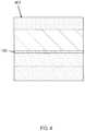
- FIG. 4shows a typical structure of a road with flexible pavement, with the fabric disclosed herein incorporated in the structure according to one instantiation.
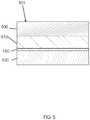
- FIG. 5shows a typical structure of a road with concrete pavement, with the fabric disclosed herein incorporated in the structure according to another instantiation.
- FIG. 6shows a typical situation in which the fabric disclosed herein is being used to image a defect in a road.
- FIG. 7shows an image of road damage as it might appear on a sensor assembly display as disclosed herein.
- FIG. 8shows a fabric detail according to an instantiation.
- FIG. 9shows a possible block diagram of a sensor assembly according to an instantiation disclosed herein.
- FIG. 10shows a possible flow chart of software for a sensor assembly according to an instantiation disclosed herein.
- FIG. 11shows a fabric detail according to another instantiation.
- FIG. 12illustrates a regular array of RFID tags forming a fabric.
- An intelligent fabricis built into such a road, either inside or between pavement layers, when said road is constructed or rebuilt.
- a sensor assembly 110may be conveyed 160 along a road 100 by a vehicle 140 to detect cavities or other subsurface weaknesses 130 anywhere within the road or some lanes of said road.
- said sensor assemblyactivates said fabric remotely, damage to said fabric, and thus to said road, can be detected.
- the possible damagecan be shown as an image, activate an alarm, be stored for future examination, or any combination of these actions.
- roadshould be understood to include any paved or non-paved way which is earth-supported, including roads, highways, airport runways, ground-surface railway tracks, and dikes.
- fabricrefers to a material in the general form of a sheet or mesh, which has a predetermined width which is a major fraction of the width of a road or one lane of a road, and a length typically larger than several car lengths.
- intelligent fabricrefers to a fabric which includes means for determining and reporting its own physical condition.
- regular arrayrefers to a repeated pattern used in forming a fabric, such that all regions of the fabric have approximately the same geometric pattern.
- the word “sensor”refers to a to a device for detecting or measuring some physical phenomenon.
- sensor assemblyrefers to an assemblage of one or more sensors of a specific type, together with electronics and computing capabilities suitable for gathering data from the sensors and processing it into a useful form.
- the verb “monitor”refers to the process of observing, measuring, or examining an object or phenomenon, either continuously or periodically.
- RFID sensorrefers to an electronic device which can send a radio frequency query to an RFID tag, and can receive the response if any.
- RFID tagrefers to a non-powered electronic device capable of detecting and responding to a radio-frequency inquiry from an RFID sensor.
- RFID tagsare very small, very inexpensive microelectronic components with an ability to detect and respond to an electronic (radio) query. Power for an RFID tag response comes from said query, so an RFID tag does not need any additional power source.
- a very common use for RFID tags and sensorsis in a retail store's theft management system, where an RFID tag embedded in the merchandise can respond when queried by electronic gates at a store exit. If a customer has properly paid for merchandise, a store clerk will have disabled said RFID tag and said customer will be allowed to leave.
- looprefers to an electrical circuit comprising several wire segments connected to form a resonant circuit which is resonant at a specified frequency. Said resonant frequency does not depend on the exact shape of the loop (square, hexagonal, etc) but only on the total perimeter.
- loop sensorrefers to an electronic device which can detect whether it is close to a loop of a specified resonant frequency.
- location sensorrefers to a means for reporting the current time and location.
- Said meanscan be a global positioning system (GPS), or measurement devices known as inertial systems which discover location by monitoring vehicle travel time and direction.
- GPSglobal positioning system
- inertial systemswhich discover location by monitoring vehicle travel time and direction.
- line bufferrefers to a computer memory element which accumulates data which constitutes one line of image data.
- the early warning system disclosed hereinprovides a method and apparatus for real-time monitoring and detection of subsurface failures of a road, highway, airport runway, railway track, river or ocean dike, or similar construction which is earth supported.
- the systemallows the presence or absence of potentially dangerous faults beneath the road to be quickly and easily discovered.
- Some implementations of the systemcomprise a material or fabric which must be built into a road, either inside or between pavement layers or above the subgrade, when said road is constructed or rebuilt, plus a sensor assembly.
- the fabricmay be embedded within the pavement of the road. There is no requirement for physical access to said fabric after road construction and said fabric is entirely passive except during examination.
- the fabricis included in the construction of a road to permit detecting potential failures in the road in such a way that stretching or tearing the fabric will cause damage to its electrical characteristics.
- the fabriccomprises a regular array of electronic circuits or devices, from which the potential for road failure can be inferred. An examination permits discovery of damage to the subsurface structure of a road, before damage becomes apparent on the surface through subsidence or collapse.
- a sensor assemblyexamines the condition of a road by detecting the physical integrity of an embedded fabric.
- the sensor assemblycomprises a linear sensor array of a predetermined number of radio frequency transmitter and receiver pairs which form sensors whose characteristics match the electrical characteristics of the embedded fabric.
- the sensor assemblycan include a vehicle or other means to move the linear sensor array along the road, such that the array of sensors is deployed across the road while the vehicle is moving along the road.
- the sensor assemblymay also include signal processing hardware and software which collects and accumulates data from the array of radio frequency devices, so that defects in or beneath said road can be discovered.
- the sensor assemblyWhen the sensor assembly activates the fabric remotely, damage to the fabric, such as a tear, becomes apparent. This damage is assumed to imply possible damage to road structure, and can be shown as an image or automatically processed using conventional image-processing techniques.
- the sensor assemblyis constructed to detect potential failures across the full width of a road or road lane.
- FIG. 1shows a top view of a method and apparatus to monitor the subsurface condition of a road 100 , which in some implementations may be highway, airport runway, or similar construction which is earth supported.
- Said roadincludes a fabric 150 (not visible in FIG. 1 ) which can determine and report its own physical condition.
- a sensor assembly 110 for examining a condition of a road by detecting the physical integrity of an embedded fabricis conveyed 160 along said road by a vehicle 140 to detect cavities or other subsurface weaknesses 130 which develop over time.
- the sensor assemblyincludes a predetermined number of sensors 120 arranged transversely to the direction of motion of said sensor assembly.
- the sensor assemblycomprises a linear sensor array of a predetermined number of radio frequency transmitter and receiver pairs which form sensors whose characteristics match the electrical characteristics of the embedded fabric.
- other means than a vehiclemay be used to move 160 the array along the road, such that the array of sensors is deployed across the road while the array is being moved 160 along the road.
- the sensor assemblymay also include signal processing hardware and software which collects and accumulates data from the array of radio frequency devices. Thus, defects in or beneath the road can be discovered.
- the sensor array apparatusincluding the signal processing hardware and software, is mounted in or on a vehicle, an operator of the vehicle may be immediately alerted to road problems.
- FIG. 2shows a side view of the method and apparatus shown in FIG. 1 along section line 2 - 2 .
- a fabric 150is built into the road 100 foundation during road construction or rebuilding. When a subsurface weakness or cavity 130 develops, said fabric tears 210 or is otherwise damaged. This damage or tear in the fabric 210 can be detected easily and inexpensively using the above-road sensor assembly 110 .
- FIG. 3shows a cross section of a typical road 301 built with a flexible pavement according to modern design.
- a roadwill have a variable number of layers and sublayers, depending on the purpose and geographic location of the road.
- the surfacingmay include a base course 300 and a wearing course 310 .
- Both the roadbase 320 and the subbase 330may comprise one or several sublayers.
- the subgradeis the earth which supports the road.
- a road with rigid pavementwill be approximately the same except that the surfacing is replaced by a concrete slab.
- FIG. 4shows a cross section of road 401 , similar to road 301 , but with the fabric 150 added.
- the fabric 150comprises a regular array of electronic circuits or devices, from which potential for road failure can be inferred.
- the fabricmay comprise a regular array of a plurality of microelectronic devices which can respond to a radio-frequency signal, such that damage to the fabric also damages one or more of the microelectronic devices to an extent that the device can no longer respond to the radio-frequency signal.
- damage to the fabriccan be detected and potential for road failure can be inferred therefrom.
- FIG. 5shows a cross section of a road 501 with rigid pavement comprising a concrete slab 500 , one or more road courses 510 , subbase 530 , and fabric 150 .
- the subbase 530may comprise one or several sublayers.
- the fabric 150comprises a regular array of electronic circuits or devices, from which potential for road failure can be inferred.
- the fabricmay comprise a regular array of a plurality of interconnected wires which can respond to a radio-frequency signal at a frequency which matches the prespecified resonant frequency of the array of wires, such that damage to the fabric also breaks one or more of the wires or wire segments thereby changing the resonant frequency of the damaged region of said fabric which includes the broken wire or wire segment.
- damage to the fabric 150can be detected and potential for road failure can be inferred therefrom.
- FIG. 6shows a cross section of a road 501 , under which a cavity 130 has appeared.
- a fabric 150 built into the road 501will remain in more-or-less the same condition as when the road was built.
- the cavity 130which might be an actual opening or a collapsed abandoned mine shaft or tunnel, or just an unexpected compression of the subgrade appears
- the road courses 510below the concrete slab 500 or other surface layer (not shown) sag 600 towards said cavity. This reduces the support for said concrete slab 500 .
- said concrete slabis likely to fail, particularly when subject to a heavy load.
- the tear or damage 210 to said fabriccan be detected easily and inexpensively using the above-road sensor assembly disclosed herein.
- FIG. 7shows an image of a cavity which appears as an irregular gap 710 against an otherwise uniform background pattern 720 on a display.
- the data being gathered from the sensors in said sensor assembly and shown on said displayare processed in ways which are well-known to image processing professionals.
- FIG. 8shows a detail of a fabric which is the first embodiment.
- RFID tags 810are arranged in the fabric in such a way that adjacent tags do not touch each other. In other words, adjacent RFID tags are not in electrical contact with each other.
- an RFID tagincludes a head, where the electronics are, and a tail, or antenna, which is really just a piece of wire or other conductive material to receive and transmit radio waves.
- Each of the tagshas a tail, or antenna 820 , which extends along said fabric.
- a fabric tear or damagebreaks 830 the antennas of some RFID tags and therefore renders some of said RFID tags inoperable.
- FIG. 9shows a block diagram for one possible implementation of a sensor assembly to be used with said fabric.
- An array 110 of sensors 120produces measurements which are converted to digital form using conventional analog-to-digital converters (A/D, 920 ), and made available to a multiplexor (MUX, 930 ).
- a microprocessor or other computer 940 with associated memorycollects said measurements in sequence.
- the computer 940may be implemented in a number of different forms. For example, it may be implemented as a cellular telephone. It may also be implemented as part of a smart phone, personal digital assistant, a computer tablet, or other similar mobile device, or a laptop or personal computer (PC), or as an embedded system.
- One set of measurementsconstitutes one line of data across a road.
- Each such lineis tagged with exact time and location from a location sensor such as a geographic positioning system receiver (GPS, 960 ) or the like and saved to a disk file 950 or the like for later processing and/or displayed as one line of an image on a display 970 and/or used to warn the operator of said sensor assembly by triggering an alarm 980 or other indicium.
- a location sensorsuch as a geographic positioning system receiver (GPS, 960 ) or the like and saved to a disk file 950 or the like for later processing and/or displayed as one line of an image on a display 970 and/or used to warn the operator of said sensor assembly by triggering an alarm 980 or other indicium.
- GPSgeographic positioning system receiver
- the sensor assembly for examining the condition of a road by detecting a physical integrity of an embedded fabriccomprises a linear sensor array, a means to move the linear sensor array along the road so that the array of sensors is deployed across the road while being moved along the road, and remotely located signal processing hardware and/or software at some other location, so that more extensive processing or less expensive sensor assemblies may be used.
- the linear sensor arraymay be a predetermined number of radio frequency transmitter and receiver pairs which form sensors whose characteristics match the electrical characteristics of the embedded fabric.
- the means to move the array along the roadmay be a vehicle or the like.
- the signal processing hardware and softwarecollects and accumulates data from the array of radio frequency devices. Thus, defects in or beneath the road can be discovered.
- the sensor array apparatusmay include some signal processing hardware and software which are mounted in or on the vehicle or other means of moving the array in addition to the remotely located signal processing hardware and/or software. The operator of the vehicle may be immediately alerted to road problems via the hardware and software mounted in or on the vehicle. In some implementations, the sensor array is mounted in or on the vehicle or other means of moving the array and data is recorded or transmitted to the signal processing hardware and software at some other location, whereby more extensive processing or less expensive sensor assemblies may be used.
- FIG. 10shows a flow chart for one possible implementation of software for a sensor assembly to be used with the fabric disclosed herein.
- Said softwarecomprises an infinite cycle in which it first gets time and location data 1020 . For each sensor in an array which is transverse to the travel direction said software then obtains measured sensor data 1030 , checks to see whether said data indicates a damaged fabric 1040 , and stores this information in a line buffer 1050 memory. After all sensors in said array have been processed 1060 said software may write said line buffer contents to disk 1070 and/or append said line buffer contents to an on-going display 1080 and/or produce an alert in some other way. All above-listed steps are then repeated.
- RFID tagsAll of the following items are available off-the-shelf and in customized versions from electronics suppliers, and are not described in detail here: RFID tags, RFID sensors, radio frequency transmitters and receivers, analog-to-digital converters, multiplexors, and microprocessor components and systems.
- Free and open-source software available for image processingincludes OpenCV from Intel® Corporation, and OpenGL from OpenGL.org.
- the condition of the lower layers of a roadis determined by passing a linear array of RFID sensors along the surface of said road. As said sensors pass over RFID tags embedded in said road, only RFID tags which are not damaged will respond. Thus, as shown in FIG. 7 , a matrix 720 of data points is derived which reveals which RFID tags are inoperable.
- FIG. 11shows a detail of a fabric which is another embodiment.
- Wires 1110 which make up said fabricare arranged in a mesh, wherein said wires are electrically connected at each intersection 1120 .
- Each set of wire segments and connectionsforms a loop 1130 with a specific resonant frequency.
- said loopsWhen said loops are intact they will resonate and absorb energy at a prespecified intended frequency when a radio frequency transmitter is in operation close to said loop. Said energy absorption can be detected using well-known methods.
- the remaining wiresform broken loops 1150 that will no longer resonate and absorb energy at the prespecified intended frequency. This is a principle well known to radio amateurs and others in the field.
- the condition of the lower layers of a roadis determined by passing a linear array of radio frequency transmitters along the surface of said road. As said transmitters pass over the loops, only those loops which are not damaged will respond at the prespecified resonant frequency. Thus, as shown in FIG. 7 , a matrix 710 of data points is derived which reveals which wires have been broken.
- FIG. 12shows a detail of a fabric in another embodiment.
- RFID tags 810are arranged in a regular array in the general form of a sheet or mesh thereby forming a fabric as described herein above.
- Each RFID tag 810has an antenna 820 which extends towards, but does not touch, the head of an adjacent RFID tag. When an RFID tag is damaged 830 it is rendered inoperable.
- the early warning system disclosed hereinprovides a method and apparatus for real-time monitoring and detection of subsurface failures of a road, highway, airport runway, railway track, river or ocean dike, or similar construction which is earth supported.
- Deterioration of subsurface structure of a roadcan lead to unanticipated collapse of said road, which in turn causes expenses to perform emergency repairs, economic losses due to traffic rerouting, possible destruction of property, injury to people or animals, and even death.
- FIG. 10 and FIG. 11Collection, processing, and presentation of sensor array data are well-known in the industry.
- the arrangements in FIG. 10 and FIG. 11are only intended to show one way that such processing could be done.
- FIG. 7 , FIG. 8 , and FIG. 11show square arrays, the arrays need not be square and could be other shapes such as rectangular, triangular, or hexagonal.
- various implementations of the systems and methods described herecan be realized in digital electronic circuitry, integrated circuitry, specially designed ASICs (application specific integrated circuits), computer hardware, firmware, software, and/or combinations thereof.
- ASICsapplication specific integrated circuits
- These various implementationscan include implementation in one or more computer programs that are executable and/or interpretable on a programmable system including at least one programmable processor, which may be special or general purpose, coupled to receive data and instructions from, and to transmit data and instructions to, a storage system, at least one input device, and at least one output device.
- These computer programsinclude machine instructions for a programmable processor, and can be implemented in a high-level procedural and/or object-oriented programming language, and/or in assembly/machine language.
- the systems and techniques described herecan be implemented on a computer with or without a display device (e.g., a CRT (cathode ray tube) or LCD (liquid crystal display) monitor) for displaying information to the user and with or without a keyboard and a pointing device (e.g., a mouse or a trackball) by which the user can provide input to the computer.
- a display devicee.g., a CRT (cathode ray tube) or LCD (liquid crystal display) monitor
- keyboard and a pointing devicee.g., a mouse or a trackball
- Other kinds of devicescan be used to provide for interaction with the user as well; for example, feedback provided to the user can be any form of sensory feedback (e.g., visual feedback, auditory feedback, or tactile feedback); and input from the user can be received in any form, including acoustic, speech, or tactile input.
- the systems and methods described herecan be implemented in a computing system that includes a back end component (e.g., as a data server), or that includes a middleware component (e.g., an application server), or that includes a front end component (e.g., a client computer having a graphical user interface or a Web browser through which the user can interact with an implementation of the systems and techniques described here), or any combination of such back end, middleware, or front end components.
- the components of the systemcan be interconnected by any form or medium of digital data communication (e.g., a communication network). Examples of communication networks include a local area network (“LAN”), a wide area network (“WAN”), and the Internet.
- LANlocal area network
- WANwide area network
- the Internetthe global information network
- the computing systemcan include clients and servers.
- a client and serverare generally remote from each other and typically interact through a communication network.
- the relationship of client and serverarises by virtue of computer programs running on the respective computers and having a client-server relationship to each other.
- systems described hereinmay be implemented via a combination of hardware and software, as described, or entirely in hardware elements.
- the particular division of functionality between the various system components described hereinis merely example, and not mandatory; functions performed by a single system component may instead be performed by multiple components, and functions performed by multiple components may instead performed by a single component.
- any such resulting programhaving computer-readable and/or computer-executable instructions, may be embodied or provided within one or more computer-readable media, thereby making a computer program product, i.e., an article of manufacture.
- the computer-readable mediamay be, for instance, a fixed (hard) drive, diskette, optical disk, magnetic tape, semiconductor memory such as read-only memory (ROM) or flash memory, etc., or any transmitting/receiving medium such as the Internet or other communication network or link.
- the article of manufacture containing the computer codemay be made and/or used by executing the instructions directly from one medium, by copying the code from one medium to another medium, or by transmitting the code over a network.
Landscapes
- Engineering & Computer Science (AREA)
- Life Sciences & Earth Sciences (AREA)
- Chemical & Material Sciences (AREA)
- Health & Medical Sciences (AREA)
- Physics & Mathematics (AREA)
- General Physics & Mathematics (AREA)
- Pathology (AREA)
- Analytical Chemistry (AREA)
- Biochemistry (AREA)
- General Health & Medical Sciences (AREA)
- Immunology (AREA)
- Food Science & Technology (AREA)
- Medicinal Chemistry (AREA)
- General Engineering & Computer Science (AREA)
- Environmental & Geological Engineering (AREA)
- Civil Engineering (AREA)
- Structural Engineering (AREA)
- General Life Sciences & Earth Sciences (AREA)
- Geology (AREA)
- Remote Sensing (AREA)
- Architecture (AREA)
- Emergency Management (AREA)
- Mechanical Engineering (AREA)
- Ocean & Marine Engineering (AREA)
- Business, Economics & Management (AREA)
- Computer Networks & Wireless Communication (AREA)
- Geophysics And Detection Of Objects (AREA)
- Road Repair (AREA)
- Chemical Kinetics & Catalysis (AREA)
- Electrochemistry (AREA)
Abstract
Description
Claims (16)
Priority Applications (8)
| Application Number | Priority Date | Filing Date | Title |
|---|---|---|---|
| US14/467,069US10866227B2 (en) | 2014-02-03 | 2014-08-25 | Early warning system for road, runway, and railway failures |
| TW104101439ATW201531422A (en) | 2014-02-03 | 2015-01-16 | Early warning system for road, runway, and railway failures |
| EP15743620.5AEP3103066B1 (en) | 2014-02-03 | 2015-01-27 | Early warning system for road, runway, and railway failures |
| JP2016549072AJP2017511877A (en) | 2014-02-03 | 2015-01-27 | Early warning system for road, runway and railway damage |
| PCT/US2015/012971WO2015116547A1 (en) | 2014-02-03 | 2015-01-27 | Early warning system for road, runway, and railway failures |
| CA2975584ACA2975584A1 (en) | 2014-02-03 | 2015-01-27 | Early warning system for road, runway, and railway failures |
| CN201580006951.2ACN105960648A (en) | 2014-02-03 | 2015-01-27 | Early warning systems for road, lane and railway obstructions |
| KR1020167019572AKR20160117438A (en) | 2014-02-03 | 2015-01-27 | Early warning system for road, runway, and railway failures |
Applications Claiming Priority (2)
| Application Number | Priority Date | Filing Date | Title |
|---|---|---|---|
| US201461934853P | 2014-02-03 | 2014-02-03 | |
| US14/467,069US10866227B2 (en) | 2014-02-03 | 2014-08-25 | Early warning system for road, runway, and railway failures |
Publications (2)
| Publication Number | Publication Date |
|---|---|
| US20150219576A1 US20150219576A1 (en) | 2015-08-06 |
| US10866227B2true US10866227B2 (en) | 2020-12-15 |
Family
ID=53754624
Family Applications (1)
| Application Number | Title | Priority Date | Filing Date |
|---|---|---|---|
| US14/467,069ActiveUS10866227B2 (en) | 2014-02-03 | 2014-08-25 | Early warning system for road, runway, and railway failures |
Country Status (8)
| Country | Link |
|---|---|
| US (1) | US10866227B2 (en) |
| EP (1) | EP3103066B1 (en) |
| JP (1) | JP2017511877A (en) |
| KR (1) | KR20160117438A (en) |
| CN (1) | CN105960648A (en) |
| CA (1) | CA2975584A1 (en) |
| TW (1) | TW201531422A (en) |
| WO (1) | WO2015116547A1 (en) |
Cited By (1)
| Publication number | Priority date | Publication date | Assignee | Title |
|---|---|---|---|---|
| US11767019B1 (en)* | 2022-04-27 | 2023-09-26 | Nanjing Hydraulic Research Institute Under The Ministry Of Water Resources, The Ministry Of Transport And The National Energy Administration | Vehicle-mounted equipment for rapid detection of danger and hidden danger of a dike and operation method thereof |
Families Citing this family (9)
| Publication number | Priority date | Publication date | Assignee | Title |
|---|---|---|---|---|
| KR101793830B1 (en)* | 2015-06-18 | 2017-11-03 | 한국지질자원연구원 | System and method for rapidly detecting a sink hole |
| TWI568998B (en)* | 2016-05-10 | 2017-02-01 | Effective monitoring device and maintenance method for road hand - hole structure | |
| CN108995675B (en)* | 2018-06-28 | 2020-07-24 | 上海工程技术大学 | A kind of rail transit operation risk intelligent identification early warning system and method |
| US11221308B2 (en)* | 2020-01-06 | 2022-01-11 | Toyota Motor Engineering & Manufacturing North America, Inc. | Intelligent road pothole detection |
| WO2021155364A1 (en) | 2020-01-30 | 2021-08-05 | Tensar International Corporation | Sensor-enabled system and method for monitoring the health, condition, and/or status of pavement and vehicular infrastructure |
| IT202000027299A1 (en)* | 2020-11-13 | 2022-05-13 | Sias S P A | METHOD AND SYSTEM FOR MONITORING AT LEAST ONE ROAD SUPPORT STRUCTURE AND ROAD SUPPORT STRUCTURE |
| WO2023243612A1 (en)* | 2022-06-13 | 2023-12-21 | 株式会社村田製作所 | Concrete structural body, concrete inspection system, and rfid device |
| CN115404739B (en)* | 2022-09-30 | 2023-08-15 | 湖北工业大学 | A road or airport embedded pipe layout structure and method for temperature control and removal |
| KR102657083B1 (en) | 2024-03-06 | 2024-04-12 | 주식회사 아이리스테크놀로지 | Apparatus for detecting underground with GPR |
Citations (41)
| Publication number | Priority date | Publication date | Assignee | Title |
|---|---|---|---|---|
| US4190776A (en) | 1977-01-18 | 1980-02-26 | Furman Anatoly V | Multipoint measuring device |
| US4795998A (en)* | 1984-05-04 | 1989-01-03 | Raychem Limited | Sensor array |
| US5287740A (en) | 1991-09-27 | 1994-02-22 | Geo Search Co., Ltd. | Method for locating and examining cavities under paved roads |
| US5298987A (en) | 1990-10-04 | 1994-03-29 | Geo Search Co., Ltd. | Method for investigating ground structure of pavement |
| DE19534677A1 (en) | 1994-09-30 | 1996-04-11 | Hubert Reidick | Landfill base seal monitoring appts. |
| US5852243A (en) | 1997-07-21 | 1998-12-22 | J-Squared, Llc | Method and apparatus for detecting a road pavement surface condition |
| US20020154029A1 (en)* | 1999-02-26 | 2002-10-24 | Sri International | Sensor devices for structural health monitoring |
| US20030012411A1 (en) | 2001-07-13 | 2003-01-16 | Sjostrom Keith Jerome | System and method for displaying and collecting ground penetrating radar data |
| US6597992B2 (en) | 2001-11-01 | 2003-07-22 | Soil And Topography Information, Llc | Soil and topography surveying |
| US6615648B1 (en) | 1997-12-22 | 2003-09-09 | The Roads And Traffic Authority On New South Wales | Road pavement deterioration inspection system |
| US20030235929A1 (en)* | 2002-06-20 | 2003-12-25 | Micron Technology, Inc. | Signal sharing circuit with microelectronic die isolation features |
| US20060070450A1 (en)* | 2004-09-13 | 2006-04-06 | U.S.A. As Represented By The Administrator Of The National Aeronautics And Space Administration | System and method for detecting cracks and their location |
| US20060097877A1 (en)* | 2004-11-09 | 2006-05-11 | Fujitsu Limited | RFID tag |
| US20060202829A1 (en)* | 2005-02-28 | 2006-09-14 | Proximities, Inc. | Tamper-resistant RFID disabling apparatus |
| US20070138304A1 (en)* | 2005-12-19 | 2007-06-21 | Dorfner Konrad H | Synthetic geomaterials with transponder technology |
| US20070210966A1 (en)* | 2006-02-28 | 2007-09-13 | Thomas Howard L | Reinforcement fabrics with electronic transmission capabilities |
| US20080042653A1 (en) | 2006-06-22 | 2008-02-21 | John Bryant | Remotely reconfigurable system for mapping subsurface geological anomalies |
| US7347101B2 (en)* | 2002-07-01 | 2008-03-25 | University Of Manitoba | Measuring strain in a structure using a sensor having an electromagnetic resonator |
| US7375636B1 (en)* | 2005-12-05 | 2008-05-20 | Lawrence Joseph Martin | Apparatus and method for real time functional testing of RFID tags |
| US20090020212A1 (en)* | 2007-05-18 | 2009-01-22 | Anthony Cacace | Smart composites and method of use thereof |
| US7675289B1 (en) | 2009-07-04 | 2010-03-09 | Stolar, Inc. | Underground anomalies detection vehicle and trailer |
| US20100067991A9 (en) | 2006-02-22 | 2010-03-18 | Pierluigi Maggioni | Sheet-Like Element Such As A Net, Particularly For Geotechnical Applications |
| US20100073154A1 (en)* | 2006-10-30 | 2010-03-25 | Min-Soo Kim | Apparatus and method for providing position information and gathering information using rfid |
| US7698075B2 (en) | 2006-02-14 | 2010-04-13 | The Boeing Company | Three-dimensional structural damage localization system and method using layered two-dimensional array of capacitance sensors |
| US7788049B2 (en) | 2006-06-22 | 2010-08-31 | Bryant Consultants, Inc. | Remotely reconfigurable system for mapping subsurface geological anomalies |
| US20100225497A1 (en)* | 2006-01-26 | 2010-09-09 | National Research Council Of Canada | Surface-Mounted Crack Detection |
| US20100245057A1 (en)* | 2009-03-31 | 2010-09-30 | Aravind Chamarti | Components, systems, and methods for associating sensor data with component location |
| US7925455B2 (en) | 2008-01-24 | 2011-04-12 | The Boeing Company | Method and system for the determination of damage location |
| US7950289B2 (en) | 2006-02-03 | 2011-05-31 | Bae Systems Plc | Damage sensors |
| US20110161008A1 (en) | 2008-08-05 | 2011-06-30 | Keun-Ho Lee | Land settlement measuring apparatus and system |
| US20110291802A1 (en)* | 2010-06-01 | 2011-12-01 | The Boeing Company | Structural health management device and associated system and method |
| US20120109560A1 (en)* | 2009-02-15 | 2012-05-03 | Board Of Regents, The University Of Texas System | Remote Interrogation of a Passive Wireless Antenna Sensor |
| CN202453920U (en) | 2012-02-09 | 2012-09-26 | 浙江元亨通信技术股份有限公司 | Buried intelligent vehicle running track system |
| US20120273263A1 (en)* | 2008-12-01 | 2012-11-01 | Ramaswamy Nagarajan | Conductive Formulations For Use In Electrical, Electronic And RF Applications |
| US20120297888A1 (en)* | 2009-09-08 | 2012-11-29 | Ramaswamy Nagarajan | Wireless Passive Radio-Frequency Strain And Displacement Sensors |
| US20130018585A1 (en) | 2011-07-15 | 2013-01-17 | Technoimaging, Llc. | Method of real time subsurface imaging using electromagnetic data acquired from moving platforms |
| US8410924B2 (en) | 2007-05-04 | 2013-04-02 | Alma Mater Studiorum—Universita' di Bologna | Method and system for remote monitoring deformations of a structure |
| US20130136539A1 (en) | 2011-11-30 | 2013-05-30 | James Alvin Aardema | Paving system utilizing embedded measuring devices |
| US8472674B2 (en) | 2007-02-06 | 2013-06-25 | Naum Marmal Yevskyy | Method of surface seismic imaging using both reflected and transmitted waves |
| US20130173163A1 (en) | 2011-12-29 | 2013-07-04 | Technoimaging, Llc | Method of subsurface imaging using superposition of sensor sensitivities from geophysical data acquisition systems |
| US8510048B2 (en) | 2011-01-24 | 2013-08-13 | Raytheon Company | Method for detecting underground tunnels |
Family Cites Families (16)
| Publication number | Priority date | Publication date | Assignee | Title |
|---|---|---|---|---|
| JPS57132402A (en)* | 1981-02-10 | 1982-08-16 | Nec Corp | High-frequency branching device |
| JPS60129306A (en)* | 1983-12-17 | 1985-07-10 | 日瀝化学工業株式会社 | Detection of pavement structure due to non-destructive method |
| JPH06186349A (en)* | 1992-12-19 | 1994-07-08 | Sumitomo Electric Ind Ltd | Underground cavity detection method |
| JPH11211842A (en)* | 1998-01-29 | 1999-08-06 | Kubota Corp | Method and apparatus for measuring depth of buried object and wireless tag used for depth measurement |
| JP4225654B2 (en)* | 1999-09-30 | 2009-02-18 | 三菱マテリアル株式会社 | Object embedded position detection method and apparatus |
| JP2002257944A (en)* | 2001-03-01 | 2002-09-11 | Osaka Gas Co Ltd | Buried target detection device |
| JP2003119717A (en)* | 2001-10-18 | 2003-04-23 | Mitsui Chemicals Inc | Pavement diagnosing sheet and pavement nondestruction diagnosing method |
| US6958071B2 (en)* | 2002-07-13 | 2005-10-25 | Stryker Corporation | Surgical tool system |
| JP2005030811A (en)* | 2003-07-08 | 2005-02-03 | Toshiba Corp | Deterioration detection method for detection object and deterioration detection apparatus for detection object |
| WO2006031813A2 (en)* | 2004-09-13 | 2006-03-23 | United States Of America As Represented By The Administrator Of The National Aeronautics And Space Administration | System and method for detecting cracks and their location |
| JP2007024970A (en)* | 2005-07-12 | 2007-02-01 | Miyakawa:Kk | Resin lens manufacturing method for increasing aperture efficiency of liquid crystal display and its manufacturing apparatus |
| WO2010014859A2 (en) | 2008-07-30 | 2010-02-04 | Sal Amarillas | Device and method to evaluate condition of concrete roadways employing a radar-based sensing and data acquisition system |
| JP4784677B2 (en)* | 2009-03-31 | 2011-10-05 | ブラザー工業株式会社 | Method for manufacturing liquid discharge head |
| JP5801064B2 (en)* | 2011-03-03 | 2015-10-28 | 日本信号株式会社 | Detecting work sheet and ground penetrating radar system using this detecting work sheet |
| WO2013121564A1 (en)* | 2012-02-16 | 2013-08-22 | 株式会社日立システムズ | Rfid tag search assistance system and position marker as well as reader device |
| FR2987904B1 (en)* | 2012-03-07 | 2014-03-21 | Commissariat Energie Atomique | DEVICE FOR EVALUATING THE DISTANCE BETWEEN AN RFID LABEL AND AN INTERFACE |
- 2014
- 2014-08-25USUS14/467,069patent/US10866227B2/enactiveActive
- 2015
- 2015-01-16TWTW104101439Apatent/TW201531422A/enunknown
- 2015-01-27KRKR1020167019572Apatent/KR20160117438A/ennot_activeWithdrawn
- 2015-01-27EPEP15743620.5Apatent/EP3103066B1/enactiveActive
- 2015-01-27JPJP2016549072Apatent/JP2017511877A/enactivePending
- 2015-01-27CACA2975584Apatent/CA2975584A1/ennot_activeAbandoned
- 2015-01-27CNCN201580006951.2Apatent/CN105960648A/enactivePending
- 2015-01-27WOPCT/US2015/012971patent/WO2015116547A1/enactiveApplication Filing
Patent Citations (41)
| Publication number | Priority date | Publication date | Assignee | Title |
|---|---|---|---|---|
| US4190776A (en) | 1977-01-18 | 1980-02-26 | Furman Anatoly V | Multipoint measuring device |
| US4795998A (en)* | 1984-05-04 | 1989-01-03 | Raychem Limited | Sensor array |
| US5298987A (en) | 1990-10-04 | 1994-03-29 | Geo Search Co., Ltd. | Method for investigating ground structure of pavement |
| US5287740A (en) | 1991-09-27 | 1994-02-22 | Geo Search Co., Ltd. | Method for locating and examining cavities under paved roads |
| DE19534677A1 (en) | 1994-09-30 | 1996-04-11 | Hubert Reidick | Landfill base seal monitoring appts. |
| US5852243A (en) | 1997-07-21 | 1998-12-22 | J-Squared, Llc | Method and apparatus for detecting a road pavement surface condition |
| US6615648B1 (en) | 1997-12-22 | 2003-09-09 | The Roads And Traffic Authority On New South Wales | Road pavement deterioration inspection system |
| US20020154029A1 (en)* | 1999-02-26 | 2002-10-24 | Sri International | Sensor devices for structural health monitoring |
| US20030012411A1 (en) | 2001-07-13 | 2003-01-16 | Sjostrom Keith Jerome | System and method for displaying and collecting ground penetrating radar data |
| US6597992B2 (en) | 2001-11-01 | 2003-07-22 | Soil And Topography Information, Llc | Soil and topography surveying |
| US20030235929A1 (en)* | 2002-06-20 | 2003-12-25 | Micron Technology, Inc. | Signal sharing circuit with microelectronic die isolation features |
| US7347101B2 (en)* | 2002-07-01 | 2008-03-25 | University Of Manitoba | Measuring strain in a structure using a sensor having an electromagnetic resonator |
| US20060070450A1 (en)* | 2004-09-13 | 2006-04-06 | U.S.A. As Represented By The Administrator Of The National Aeronautics And Space Administration | System and method for detecting cracks and their location |
| US20060097877A1 (en)* | 2004-11-09 | 2006-05-11 | Fujitsu Limited | RFID tag |
| US20060202829A1 (en)* | 2005-02-28 | 2006-09-14 | Proximities, Inc. | Tamper-resistant RFID disabling apparatus |
| US7375636B1 (en)* | 2005-12-05 | 2008-05-20 | Lawrence Joseph Martin | Apparatus and method for real time functional testing of RFID tags |
| US20070138304A1 (en)* | 2005-12-19 | 2007-06-21 | Dorfner Konrad H | Synthetic geomaterials with transponder technology |
| US20100225497A1 (en)* | 2006-01-26 | 2010-09-09 | National Research Council Of Canada | Surface-Mounted Crack Detection |
| US7950289B2 (en) | 2006-02-03 | 2011-05-31 | Bae Systems Plc | Damage sensors |
| US7698075B2 (en) | 2006-02-14 | 2010-04-13 | The Boeing Company | Three-dimensional structural damage localization system and method using layered two-dimensional array of capacitance sensors |
| US20100067991A9 (en) | 2006-02-22 | 2010-03-18 | Pierluigi Maggioni | Sheet-Like Element Such As A Net, Particularly For Geotechnical Applications |
| US20070210966A1 (en)* | 2006-02-28 | 2007-09-13 | Thomas Howard L | Reinforcement fabrics with electronic transmission capabilities |
| US20080042653A1 (en) | 2006-06-22 | 2008-02-21 | John Bryant | Remotely reconfigurable system for mapping subsurface geological anomalies |
| US7788049B2 (en) | 2006-06-22 | 2010-08-31 | Bryant Consultants, Inc. | Remotely reconfigurable system for mapping subsurface geological anomalies |
| US20100073154A1 (en)* | 2006-10-30 | 2010-03-25 | Min-Soo Kim | Apparatus and method for providing position information and gathering information using rfid |
| US8472674B2 (en) | 2007-02-06 | 2013-06-25 | Naum Marmal Yevskyy | Method of surface seismic imaging using both reflected and transmitted waves |
| US8410924B2 (en) | 2007-05-04 | 2013-04-02 | Alma Mater Studiorum—Universita' di Bologna | Method and system for remote monitoring deformations of a structure |
| US20090020212A1 (en)* | 2007-05-18 | 2009-01-22 | Anthony Cacace | Smart composites and method of use thereof |
| US7925455B2 (en) | 2008-01-24 | 2011-04-12 | The Boeing Company | Method and system for the determination of damage location |
| US20110161008A1 (en) | 2008-08-05 | 2011-06-30 | Keun-Ho Lee | Land settlement measuring apparatus and system |
| US20120273263A1 (en)* | 2008-12-01 | 2012-11-01 | Ramaswamy Nagarajan | Conductive Formulations For Use In Electrical, Electronic And RF Applications |
| US20120109560A1 (en)* | 2009-02-15 | 2012-05-03 | Board Of Regents, The University Of Texas System | Remote Interrogation of a Passive Wireless Antenna Sensor |
| US20100245057A1 (en)* | 2009-03-31 | 2010-09-30 | Aravind Chamarti | Components, systems, and methods for associating sensor data with component location |
| US7675289B1 (en) | 2009-07-04 | 2010-03-09 | Stolar, Inc. | Underground anomalies detection vehicle and trailer |
| US20120297888A1 (en)* | 2009-09-08 | 2012-11-29 | Ramaswamy Nagarajan | Wireless Passive Radio-Frequency Strain And Displacement Sensors |
| US20110291802A1 (en)* | 2010-06-01 | 2011-12-01 | The Boeing Company | Structural health management device and associated system and method |
| US8510048B2 (en) | 2011-01-24 | 2013-08-13 | Raytheon Company | Method for detecting underground tunnels |
| US20130018585A1 (en) | 2011-07-15 | 2013-01-17 | Technoimaging, Llc. | Method of real time subsurface imaging using electromagnetic data acquired from moving platforms |
| US20130136539A1 (en) | 2011-11-30 | 2013-05-30 | James Alvin Aardema | Paving system utilizing embedded measuring devices |
| US20130173163A1 (en) | 2011-12-29 | 2013-07-04 | Technoimaging, Llc | Method of subsurface imaging using superposition of sensor sensitivities from geophysical data acquisition systems |
| CN202453920U (en) | 2012-02-09 | 2012-09-26 | 浙江元亨通信技术股份有限公司 | Buried intelligent vehicle running track system |
Non-Patent Citations (14)
| Title |
|---|
| ASTM, Prediction of Flexible Pavement Layer Moduli from Dynaflect and FWD Deflections, American Society for Testing and Materials (ASTM) Report STP1026 [abstract only online], Jan. 1989 [retrieved on approximately Dec. 31, 2013] Retrieved from the Internet <URL: www.astm.org/DIGITAL_LIBRARY/STP/PAGES/STP19811S.htm>. |
| Bonnet, Clifford F., Practical Railway Engineering, 2nd Edition, Imperial College Press, London, England, 2005. ISBN 1 86094 515 5, especially p. 86. |
| Cardimona, S. at al, Ground Penetrating Radar Survey of Interstate 70 Across Missouri, The University of Missouri-Rolla, Department of Geology and Geophysics and The Missouri Department of Transportation [online], pp. 5, 6, and especially 7 [retrieved on approximately Dec. 31, 2013] Retrieved from the Internet <URL: transportation.mst.edu/media/research/transportation/documents/i70.pdf>. |
| Cardimona, S. at al, Ground Penetrating Radar Survey of Interstate 70 Across Missouri, The University of Missouri—Rolla, Department of Geology and Geophysics and The Missouri Department of Transportation [online], pp. 5, 6, and especially 7 [retrieved on approximately Dec. 31, 2013] Retrieved from the Internet <URL: transportation.mst.edu/media/research/transportation/documents/i70.pdf>. |
| Daley, Margaret A. et al, Seismic Refraction Data Collected in the Chugach Mountains and along the Glenn Highway in southern Alaska in 1984, United States Department of the Interior Geologial Survey Open-File Report 85-531 [online], 1985, pp. 1 and 3, [retrieved on approximately Dec. 31, 2013] Retrieved from the Internet <URL: pubs.er.usgs.gov/publication/ofr85531>. |
| Garber, Nicholas J. and Noel, Lester A., Traffic and Highway Engineering, 4th Edition, Cengage Learning, Stamford CT, 2010, ISBN 0 495 43853 7, pp. 1133-1151. |
| O'Flaherty, C.A., "Highways: The Location Design, Construction and Maintenance of Road Pavements, 4th Edition", Elsevier, Woburn MA, 2002,ISBN 0 7506 5090 7, especially pp. 34-52. |
| Portas, S et al,"Field Testing and Modelling of the Italian Smart Runway Instrumentations",2010 FAA Worldwide Technology Transfer Conference, Federal Avionics Administration, Atlantic City New Jersey, Apr. 2010. |
| Sperring, D.G. "A Review of the Effects of Natural Damage" In Cost Effective Maintenance of Railway Track Edited by R. A. Vickers, Institution of Civil Engineers, 2002, ISBN 0 7277 1930 0, pp. 105-116. |
| Sugumaran, Ramanathan et al,"Transportation Infrastructure Extraction" In: Remote Sensing of Impervious Surfaces edited by Qihau Weng, CRC Press, Boca Raton, FL, 2008, ISBN 1 4200 4374 9 especially p. 175. |
| The U.S. Department of Transportation FHA, Ground-Penetrating Radar, Federal Highway Administration (FHA), [online] undated report FHWA-HRT-04-072,HRTS-03/01-04(1M)E [retrieved on approximately Dec. 31, 2013] Retrieved from the Internet <URL: www.fhwa.dot.gov/pavement/groundpr.pdf >. |
| Transit New Zealand, "Standard Test Procedure for Benkelman Beam Deflection Measurements", Transit New Zealand Publication T/1, Jun. 1977. |
| Transportation Research Board of the National Academies, "Automated Sensing for Construction Quality Monitoring of Concrete Pavements, and Smart Long-Term Tagging System", Transportation Research Board (TRB) Research Needs Statement, [online] 2013, [retrieved on approximately Dec. 31, 2013] retrieved from the Internet <URL: rns.trb.org/dproject.asp?n=33481>. |
| Yang, S. et al, "Smart Airport Pavement Instrumentation and Health Monitoring", 2014 FAA Worldwide Technology Transfer Conference, Federal Avionics Administration, Galloway, New Jersey, Apr. 2014. |
Cited By (1)
| Publication number | Priority date | Publication date | Assignee | Title |
|---|---|---|---|---|
| US11767019B1 (en)* | 2022-04-27 | 2023-09-26 | Nanjing Hydraulic Research Institute Under The Ministry Of Water Resources, The Ministry Of Transport And The National Energy Administration | Vehicle-mounted equipment for rapid detection of danger and hidden danger of a dike and operation method thereof |
Also Published As
| Publication number | Publication date |
|---|---|
| CN105960648A (en) | 2016-09-21 |
| US20150219576A1 (en) | 2015-08-06 |
| TW201531422A (en) | 2015-08-16 |
| EP3103066A4 (en) | 2017-08-30 |
| JP2017511877A (en) | 2017-04-27 |
| EP3103066B1 (en) | 2021-11-24 |
| KR20160117438A (en) | 2016-10-10 |
| WO2015116547A1 (en) | 2015-08-06 |
| EP3103066A1 (en) | 2016-12-14 |
| CA2975584A1 (en) | 2015-08-06 |
Similar Documents
| Publication | Publication Date | Title |
|---|---|---|
| US10866227B2 (en) | Early warning system for road, runway, and railway failures | |
| Selvakumaran et al. | Remote monitoring to predict bridge scour failure using Interferometric Synthetic Aperture Radar (InSAR) stacking techniques | |
| Smethurst et al. | Current and future role of instrumentation and monitoring in the performance of transport infrastructure slopes | |
| Rasol et al. | NDT assessment of rigid pavement damages with ground penetrating radar: laboratory and field tests | |
| Vaziri et al. | Monitoring systems for warning impending failures in slopes and open pit mines | |
| EP2965124B1 (en) | A system and method for evaluating a dam state | |
| Muller | A comparison of TSD, FWD and GPR field measurements | |
| Kelam et al. | Utilization of optical fiber system for mass movement monitoring | |
| Cai et al. | Research progress of intelligent testing technology and evaluation methods for subgrade engineering | |
| Kane et al. | An alternative monitoring system for unstable slopes | |
| Guéguen et al. | Condition-based decision using traffic-light concept applied to civil engineering buildings | |
| Rudahl et al. | A Smart Geofabric for Detecting Transportation Substructure Damage | |
| Khatiwada et al. | Evaluation of the Safety of Reinforced Concrete Buildings Post-Earthquake for Swift Rescue and Recovery | |
| Boehmler et al. | Evaluation of pier-scour measurement methods and pier-scour predictions with observed scour measurements at selected bridge sites in New Hampshire, 1995-98 | |
| Rudahl et al. | A smart geosynthetic for early detection of potential transportation substructure failure | |
| Niekrasz | Review of radar system performance and estimation of slope deformation threshold values for the Leveäniemi open pit | |
| Cusson et al. | Satellite sensing technology to monitor bridges and other civil infrastructures | |
| Ramanathan et al. | Analysis of the 1997 Chandmari Landslide, India, and technology-enabled risk reduction | |
| Selvakumarana et al. | Int J Appl Earth Obs Geoinformation | |
| Depan et al. | A Case Study of Automatically Monitoring System Experiment for Landslide Within Tianfu New District in Chengdu | |
| Devendra et al. | Studying Time Domain Reflectometry to Predict Slope Failure in Open-Cast Mines | |
| Rudahl et al. | THE GROUND BENEATH OUR FEET: ENABLING SUBSURFACE SENSING | |
| Maerz et al. | Potential use of ground penetrating radar in highway rock cut stability | |
| Vardanega et al. | Recent progress developing a rating framework for evaluating SHM for bridge scour | |
| Malvar et al. | Detecting voids under airfield pavements |
Legal Events
| Date | Code | Title | Description |
|---|---|---|---|
| AS | Assignment | Owner name:HEURIKA GEOGRAPHICS PTE. LTD., SINGAPORE Free format text:NUNC PRO TUNC ASSIGNMENT;ASSIGNOR:GOLDIN-RUDAHL SYSTEMS, INC.;REEL/FRAME:047188/0236 Effective date:20181017 | |
| STPP | Information on status: patent application and granting procedure in general | Free format text:FINAL REJECTION MAILED | |
| STCV | Information on status: appeal procedure | Free format text:APPEAL BRIEF (OR SUPPLEMENTAL BRIEF) ENTERED AND FORWARDED TO EXAMINER | |
| STCV | Information on status: appeal procedure | Free format text:EXAMINER'S ANSWER TO APPEAL BRIEF MAILED | |
| STCV | Information on status: appeal procedure | Free format text:APPEAL READY FOR REVIEW | |
| STCV | Information on status: appeal procedure | Free format text:ON APPEAL -- AWAITING DECISION BY THE BOARD OF APPEALS | |
| AS | Assignment | Owner name:GOLDIN-RUDAHL SYSTEMS, INC., MASSACHUSETTS Free format text:NUNC PRO TUNC ASSIGNMENT;ASSIGNORS:RUDAHL, KURT;GOLDIN, SALLY;REEL/FRAME:054253/0556 Effective date:20201103 | |
| STPP | Information on status: patent application and granting procedure in general | Free format text:PUBLICATIONS -- ISSUE FEE PAYMENT VERIFIED | |
| STCF | Information on status: patent grant | Free format text:PATENTED CASE | |
| AS | Assignment | Owner name:GOLDIN-RUDAHL SYSTEMS, INC., MASSACHUSETTS Free format text:ASSIGNMENT OF ASSIGNORS INTEREST;ASSIGNOR:HEURIKA GEOGRAPHICS PTE. LTD.;REEL/FRAME:062429/0620 Effective date:20230108 | |
| MAFP | Maintenance fee payment | Free format text:PAYMENT OF MAINTENANCE FEE, 4TH YEAR, MICRO ENTITY (ORIGINAL EVENT CODE: M3551); ENTITY STATUS OF PATENT OWNER: MICROENTITY Year of fee payment:4 |