US10866117B2 - Magnetic field influence during rotation movement of magnetic target - Google Patents
Magnetic field influence during rotation movement of magnetic targetDownload PDFInfo
- Publication number
- US10866117B2 US10866117B2US15/909,208US201815909208AUS10866117B2US 10866117 B2US10866117 B2US 10866117B2US 201815909208 AUS201815909208 AUS 201815909208AUS 10866117 B2US10866117 B2US 10866117B2
- Authority
- US
- United States
- Prior art keywords
- magnetic field
- field sensing
- sensing element
- maximum sensitivity
- axis
- Prior art date
- Legal status (The legal status is an assumption and is not a legal conclusion. Google has not performed a legal analysis and makes no representation as to the accuracy of the status listed.)
- Active, expires
Links
Images


Classifications
- G—PHYSICS
- G01—MEASURING; TESTING
- G01D—MEASURING NOT SPECIALLY ADAPTED FOR A SPECIFIC VARIABLE; ARRANGEMENTS FOR MEASURING TWO OR MORE VARIABLES NOT COVERED IN A SINGLE OTHER SUBCLASS; TARIFF METERING APPARATUS; MEASURING OR TESTING NOT OTHERWISE PROVIDED FOR
- G01D5/00—Mechanical means for transferring the output of a sensing member; Means for converting the output of a sensing member to another variable where the form or nature of the sensing member does not constrain the means for converting; Transducers not specially adapted for a specific variable
- G01D5/12—Mechanical means for transferring the output of a sensing member; Means for converting the output of a sensing member to another variable where the form or nature of the sensing member does not constrain the means for converting; Transducers not specially adapted for a specific variable using electric or magnetic means
- G01D5/14—Mechanical means for transferring the output of a sensing member; Means for converting the output of a sensing member to another variable where the form or nature of the sensing member does not constrain the means for converting; Transducers not specially adapted for a specific variable using electric or magnetic means influencing the magnitude of a current or voltage
- G01D5/142—Mechanical means for transferring the output of a sensing member; Means for converting the output of a sensing member to another variable where the form or nature of the sensing member does not constrain the means for converting; Transducers not specially adapted for a specific variable using electric or magnetic means influencing the magnitude of a current or voltage using Hall-effect devices
- G—PHYSICS
- G01—MEASURING; TESTING
- G01D—MEASURING NOT SPECIALLY ADAPTED FOR A SPECIFIC VARIABLE; ARRANGEMENTS FOR MEASURING TWO OR MORE VARIABLES NOT COVERED IN A SINGLE OTHER SUBCLASS; TARIFF METERING APPARATUS; MEASURING OR TESTING NOT OTHERWISE PROVIDED FOR
- G01D5/00—Mechanical means for transferring the output of a sensing member; Means for converting the output of a sensing member to another variable where the form or nature of the sensing member does not constrain the means for converting; Transducers not specially adapted for a specific variable
- G01D5/12—Mechanical means for transferring the output of a sensing member; Means for converting the output of a sensing member to another variable where the form or nature of the sensing member does not constrain the means for converting; Transducers not specially adapted for a specific variable using electric or magnetic means
- G01D5/14—Mechanical means for transferring the output of a sensing member; Means for converting the output of a sensing member to another variable where the form or nature of the sensing member does not constrain the means for converting; Transducers not specially adapted for a specific variable using electric or magnetic means influencing the magnitude of a current or voltage
- G01D5/16—Mechanical means for transferring the output of a sensing member; Means for converting the output of a sensing member to another variable where the form or nature of the sensing member does not constrain the means for converting; Transducers not specially adapted for a specific variable using electric or magnetic means influencing the magnitude of a current or voltage by varying resistance
- G—PHYSICS
- G01—MEASURING; TESTING
- G01R—MEASURING ELECTRIC VARIABLES; MEASURING MAGNETIC VARIABLES
- G01R15/00—Details of measuring arrangements of the types provided for in groups G01R17/00 - G01R29/00, G01R33/00 - G01R33/26 or G01R35/00
- G01R15/14—Adaptations providing voltage or current isolation, e.g. for high-voltage or high-current networks
- G01R15/20—Adaptations providing voltage or current isolation, e.g. for high-voltage or high-current networks using galvano-magnetic devices, e.g. Hall-effect devices, i.e. measuring a magnetic field via the interaction between a current and a magnetic field, e.g. magneto resistive or Hall effect devices
- G01R15/207—Constructional details independent of the type of device used
- G—PHYSICS
- G01—MEASURING; TESTING
- G01R—MEASURING ELECTRIC VARIABLES; MEASURING MAGNETIC VARIABLES
- G01R33/00—Arrangements or instruments for measuring magnetic variables
- G01R33/02—Measuring direction or magnitude of magnetic fields or magnetic flux
- G01R33/06—Measuring direction or magnitude of magnetic fields or magnetic flux using galvano-magnetic devices
- G01R33/07—Hall effect devices
- G01R33/072—Constructional adaptation of the sensor to specific applications
- G—PHYSICS
- G01—MEASURING; TESTING
- G01R—MEASURING ELECTRIC VARIABLES; MEASURING MAGNETIC VARIABLES
- G01R33/00—Arrangements or instruments for measuring magnetic variables
- G01R33/02—Measuring direction or magnitude of magnetic fields or magnetic flux
- G01R33/06—Measuring direction or magnitude of magnetic fields or magnetic flux using galvano-magnetic devices
- G01R33/09—Magnetoresistive devices
- G01R33/091—Constructional adaptation of the sensor to specific applications
- G—PHYSICS
- G01—MEASURING; TESTING
- G01R—MEASURING ELECTRIC VARIABLES; MEASURING MAGNETIC VARIABLES
- G01R33/00—Arrangements or instruments for measuring magnetic variables
- G01R33/02—Measuring direction or magnitude of magnetic fields or magnetic flux
- G01R33/06—Measuring direction or magnitude of magnetic fields or magnetic flux using galvano-magnetic devices
- G01R33/09—Magnetoresistive devices
- G01R33/098—Magnetoresistive devices comprising tunnel junctions, e.g. tunnel magnetoresistance sensors
- G—PHYSICS
- G01—MEASURING; TESTING
- G01D—MEASURING NOT SPECIALLY ADAPTED FOR A SPECIFIC VARIABLE; ARRANGEMENTS FOR MEASURING TWO OR MORE VARIABLES NOT COVERED IN A SINGLE OTHER SUBCLASS; TARIFF METERING APPARATUS; MEASURING OR TESTING NOT OTHERWISE PROVIDED FOR
- G01D5/00—Mechanical means for transferring the output of a sensing member; Means for converting the output of a sensing member to another variable where the form or nature of the sensing member does not constrain the means for converting; Transducers not specially adapted for a specific variable
- G01D5/12—Mechanical means for transferring the output of a sensing member; Means for converting the output of a sensing member to another variable where the form or nature of the sensing member does not constrain the means for converting; Transducers not specially adapted for a specific variable using electric or magnetic means
- G01D5/14—Mechanical means for transferring the output of a sensing member; Means for converting the output of a sensing member to another variable where the form or nature of the sensing member does not constrain the means for converting; Transducers not specially adapted for a specific variable using electric or magnetic means influencing the magnitude of a current or voltage
- G01D5/142—Mechanical means for transferring the output of a sensing member; Means for converting the output of a sensing member to another variable where the form or nature of the sensing member does not constrain the means for converting; Transducers not specially adapted for a specific variable using electric or magnetic means influencing the magnitude of a current or voltage using Hall-effect devices
- G01D5/145—Mechanical means for transferring the output of a sensing member; Means for converting the output of a sensing member to another variable where the form or nature of the sensing member does not constrain the means for converting; Transducers not specially adapted for a specific variable using electric or magnetic means influencing the magnitude of a current or voltage using Hall-effect devices influenced by the relative movement between the Hall device and magnetic fields
- G—PHYSICS
- G01—MEASURING; TESTING
- G01P—MEASURING LINEAR OR ANGULAR SPEED, ACCELERATION, DECELERATION, OR SHOCK; INDICATING PRESENCE, ABSENCE, OR DIRECTION, OF MOVEMENT
- G01P3/00—Measuring linear or angular speed; Measuring differences of linear or angular speeds
- G01P3/42—Devices characterised by the use of electric or magnetic means
- G01P3/44—Devices characterised by the use of electric or magnetic means for measuring angular speed
- G01P3/48—Devices characterised by the use of electric or magnetic means for measuring angular speed by measuring frequency of generated current or voltage
- G01P3/481—Devices characterised by the use of electric or magnetic means for measuring angular speed by measuring frequency of generated current or voltage of pulse signals
- G01P3/487—Devices characterised by the use of electric or magnetic means for measuring angular speed by measuring frequency of generated current or voltage of pulse signals delivered by rotating magnets
Definitions
- This disclosurerelates to magnetic field sensors and, more particularly, to rejection of stray magnetic fields during detection.
- Magnetic field sensorsare often used to detect a rotating magnetic target.
- a magnetmay be placed at the end of a rotation shaft, such as a cam shaft or axle.
- a magnetic field sensorcan be placed adjacent to the magnet to detect it as the shaft rotates.
- the magnet and sensorare designed to detect an angular position.
- the magnetmay be positioned so that its polarity vector rotates with the shaft.
- the sensormay be designed to detect the direction of the polarity vector and calculate a positional angle of the magnet.
- Extraneous or stray magnetic fieldscan make detection of the magnet less accurate and can induce errors in calculating the angle. These fields can be present in the ambient environment or produced by nearby equipment or electronic devices.
- a systemcomprises a magnetic target producing a rotating magnetic field, a first set of magnetic field sensing elements placed in spaced relation to the magnetic target and comprising at least a first magnetic field sensing element and a second magnetic field sensing element, each magnetic field sensing element having an axis of maximum sensitivity and a second set of magnetic field sensing elements placed in spaced relation to the magnetic target and comprising at least a third magnetic field sensing element and a fourth magnetic field sensing element, each magnetic field sensing element having an axis of maximum sensitivity.
- the first set of magnetic field sensing elementsis positioned closer to a center point of the magnetic field than the second set of magnetic field sensing elements.
- the axes of maximum sensitivity of the magnetic field sensing elements of the first setmay define a plane and the axes of maximum sensitivity of the magnetic field sensing elements of the second set may define a plane.
- the plane defined by the first set and the plane defined by the second setmay be the same plane.
- the axis of maximum sensitivity of the first magnetic field sensing elementmay be orthogonal to the axis of maximum sensitivity of the second magnetic field sensing element and the axis of maximum sensitivity of the third magnetic field sensing element may be orthogonal to the axis of maximum sensitivity of the fourth magnetic field sensing element.
- the axis of maximum sensitivity of the first magnetic field sensing elementmay be parallel to the axis of maximum sensitivity of the third magnetic field sensing element and the axis of maximum sensitivity of the second magnetic field sensing element may be parallel to the axis of maximum sensitivity of the fourth magnetic field sensing element.
- the magnetic field sensing elementsmay be placed so that their respective axes of maximum sensitivity are at a respective predetermined angle with respect to the magnetic field.
- the rotating magnetic fieldmay have a direction through the first and second sets of magnetic field sensing elements wherein: the angle of the axis of maximum sensitivity of the first magnetic field sensing element is about 180 degrees with respect to a centerline defined by the first and second sets of magnetic field sensing elements; the angle of the axis of maximum sensitivity of the second magnetic field sensing element is about 90 degrees with respect to the centerline defined by the first and second sets of magnetic field sensing elements; the angle of the axis of maximum sensitivity of the third magnetic field sensing element is about 180 degrees with respect to the centerline defined by the first and second sets of magnetic field sensing elements; and the angle of the axis of maximum sensitivity of the fourth magnetic field sensing element is about 90 degrees with respect to the centerline defined by the first and second sets of magnetic field sensing elements.
- the magnetic field sensing elementsmay be placed so that their respective axes of maximum sensitivity are at a predetermined angle with respect to an expected direction of a stray magnetic field.
- the angle of the axis of maximum sensitivity of the first magnetic field sensing elementmay be about 90 degrees with respect to the expected direction of the stray magnetic field; the angle of the axis of maximum sensitivity of the second magnetic field sensing element may be about 45 degrees with respect to the expected direction of the stray magnetic field; the angle of the axis of maximum sensitivity of the third magnetic field sensing element may be about 90 degrees with respect to the expected direction of the stray magnetic field; and the angle of the axis of maximum sensitivity of the fourth magnetic field sensing element may be about 45 degrees with respect to the expected direction of the stray magnetic field.
- the targetmay comprise a body comprising a cylinder.
- a first half of the cylindermay have a first magnetic polarity and a second half of the cylinder may have a second magnetic polarity.
- the first and second halves of the cylindermay be defined by a plane through which an axis of the cylinder runs.
- the cylindermay be defined by four quadrants, where adjacent quadrants have opposite magnetic polarities.
- Each magnetic field sensing elementmay produce an output signal representing the magnetic field as detected by the respective magnetic field sensing element.
- a processing circuitmay be coupled to receive the output signals of the magnetic field sensing elements and calculate a detected angle of the magnetic field.
- the processing circuitmay be configured to cancel the effect of a stray magnetic field having a direction substantially orthogonal to a line from the first set to the second set of magnetic field sensing elements.
- the processing circuitmay include one or more of: a circuit to perform an arctangent function, a circuit to perform a sin function, and a circuit to perform a cosine function.
- a systemcomprises: a magnetic target producing a rotating magnetic field; means for detecting the magnetic field and producing one or more signals representing the magnetic field; means for calculating an angle of the rotating magnetic field from the one or more signals; and means for canceling effects of a stray magnetic field from the calculation of the angle.
- a systemcomprises a magnetic target producing a rotating magnetic field; a first set of magnetic field sensing elements placed in spaced relation to the magnetic target to detect the magnetic field; a second set of magnetic field sensing elements placed in spaced relation to the magnetic target to detect the magnetic field wherein the first set of magnetic field sensing elements is positioned closer to a center point of the magnetic field than the second set of magnetic field sensing elements so that the first set of magnetic field sensing elements detects a stronger magnetic field than the second set of magnetic field sensing elements detects; wherein the first and second set of magnetic field sensing elements are placed so that both sets detect, with approximately equal strength, a stray magnetic field.
- FIG. 1is a diagram of a system for detecting a rotating target.
- FIG. 2is a diagram of a magnetic field sensor and a magnetic target.
- FIG. 2Ais a graph of magnetic field strength versus distance.
- FIG. 3is a diagram of another embodiment of a magnetic field sensor and a magnetic target.
- FIG. 3Ais a diagram of another embodiment of a magnetic field sensor and a magnetic target.
- FIG. 3Bis a diagram of another embodiment of a magnetic field sensor and a magnetic target.
- FIG. 3Cis a diagram of another embodiment of a magnetic field sensor and a magnetic target.
- FIG. 4is a diagram of another embodiment of a magnetic field sensor and a magnetic target.
- FIG. 5is a diagram of a magnetic target with a magnetic field sensor.
- FIG. 6is a diagram of a magnetic target with positioning of a magnetic field sensor.
- FIG. 7is a diagram of a magnetic field sensor showing a processing circuit, and a magnetic target.
- magnetic field sensing elementis used to describe a variety of electronic elements that can sense a magnetic field.
- the magnetic field sensing elementcan be, but is not limited to, a Hall Effect element, a magnetoresistance element, or a magnetotransistor.
- Hall Effect elementsfor example, a planar Hall element, and a vertical Hall element.
- magnetoresistance elementsfor example, a semiconductor magnetoresistance element such as Indium Antimonide (InSb), a giant magnetoresistance (GMR) element, an anisotropic magnetoresistance element (AMR), a tunneling magnetoresistance (TMR) element, and a magnetic tunnel junction (MTJ).
- InSbIndium Antimonide
- GMRgiant magnetoresistance
- AMRanisotropic magnetoresistance element
- TMRtunneling magnetoresistance
- MTJmagnetic tunnel junction
- the magnetic field sensing elementmay be a single element or, alternatively, may include two or more magnetic field sensing elements arranged in various configurations, e.g., a half bridge or full (Wheatstone) bridge.
- the magnetic field sensing elementmay be a device made of a type IV semiconductor material such as Silicon (Si) or Germanium (Ge), or a type III-V semiconductor material like Gallium-Arsenide (GaAs) or an Indium compound, e.g., Indium-Antimonide (InSb).
- some of the above-described magnetic field sensing elementstend to have an axis of maximum sensitivity parallel to a substrate that supports the magnetic field sensing element, and others of the above-described magnetic field sensing elements tend to have an axis of maximum sensitivity perpendicular to a substrate that supports the magnetic field sensing element.
- planar Hall elementstend to have axes of sensitivity perpendicular to a substrate
- metal based or metallic magnetoresistance elementse.g., GMR, TMR, AMR
- vertical Hall elementstend to have axes of sensitivity parallel to a substrate.
- magnetic field sensoris used to describe a circuit that uses a magnetic field sensing element, generally in combination with other circuits.
- Magnetic field sensorsare used in a variety of applications, including, but not limited to, an angle sensor that senses an angle of a direction of a magnetic field, a current sensor that senses a magnetic field generated by a current carried by a current-carrying conductor, a magnetic switch that senses the proximity of a ferromagnetic object, a rotation detector that senses passing ferromagnetic articles, for example, magnetic domains of a ring magnet or a ferromagnetic target (e.g., gear teeth) where the magnetic field sensor is used in combination with a back-biased or other magnet, and a magnetic field sensor that senses a magnetic field density of a magnetic field.
- an angle sensorthat senses an angle of a direction of a magnetic field
- a current sensorthat senses a magnetic field generated by a current carried by a current-carrying conductor
- a magnetic switchthat
- targetand “magnetic target” are used to describe an object to be sensed or detected by a magnetic field sensor or magnetic field sensing element.
- FIG. 1shows an example of a system 100 for detecting a magnetic target 102 .
- Target 102may be placed at the end of rotating shaft 104 .
- rotating shaftmay be a cam shaft, an axle, a spindle, a spool, or any type of machine that rotates.
- Magnetic target 102may be polarized so that it has a north section 106 and a south section 108 .
- north section 106 and south section 108may each comprise a horizontal cylindrical segment of target 102 .
- the polarization of magnet 102may produce a magnetic field vector in the direction of vector 110 .
- a magnetic field sensor 112may be positioned adjacent to target 102 to detect the magnetic field. As shaft 104 rotates, magnetic field vector 110 may also rotate. Magnetic field sensor 112 may be configured to detect the magnetic field and the angle of its rotation.
- Magnetic field sensor 112may be communicatively coupled to a processor 114 .
- processor 114may be an in-vehicle computer that may control the vehicle based, in part, on information provided by sensor 112 .
- sensor 112may send information about the magnetic field (such as position, speed of rotation, phase, angle, etc.) to processor 114 .
- Magnetic field sensor 112may also communicate information about any errors encountered to processor 114 .
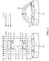
- a system 200includes a magnetic field sensor 202 , which may be the same as or similar to magnetic field sensor 112 , and a target 204 , which may be the same as or similar to target 102 .
- Target 204may produce magnetic field 206 .
- magnetic field 206 produced by target 204is illustrated by straight magnetic field lines 208 .
- the direction of magnetic field 206may be different from that shown by magnetic field lines 208 .
- magnetic field lines 208 ′may present a more realistic depiction of a magnetic field produced by target 204 .
- magnetic fieldsmay be drawn with straight lines for ease of illustration, but may take other shapes, forms, and directions depending on the type and shape of the magnetic source. Even though a magnetic field is drawn in the figures using straight lines, it does not necessarily indicate that the magnetic field has uniform field strength along those lines, unless specifically described as uniform in the text. For example, the magnetic field depicted by magnetic field lines 208 will have greater strength (e.g. flux density) around pair 218 (closer to target 204 ) and relatively weaker strength around pair 212 (further away from target 204 ).
- Magnetic field sensor 202may be positioned adjacent to target 204 to detect magnetic field 206 as target 204 rotates and compute an angle of rotation of target 204 .
- Magnetic field lines 210represent an external, or stray, magnetic field that can influence detection of magnetic field 206 by sensor 202 and potentially cause errors or inaccuracies.
- magnetic field sensor 202may include a first set 212 of magnetic field sensing elements 214 and 216 , and a second set 218 of magnetic field sensing elements 220 and 222 .
- Each setmay contain a pair of magnetic field sensing elements. In other embodiments, each set may contain more than two magnetic field sensing elements.
- Magnetic field sensing element 202may be positioned so that set 218 is closer to target 204 than set 212 .
- magnetic field sensing elements 220 and 222may be subject to and detect a stronger magnetic field 206 than that which is detected by magnetic field sensing elements 214 and 216 .
- Magnetic field 210may be a uniform magnetic field that affects magnetic field sensing elements 220 , 222 , 214 , and 216 substantially equally. Thus, in contrast to magnetic field 208 , magnetic fields sensing elements 220 , 222 , 216 , and 216 may be subject to and detect a substantially equal stray magnetic field 210 .
- Each magnetic field sensing element 214 , 216 , 220 , and 222has an axis of maximum sensitivity (as described above) represented by arrows 224 , 226 , 228 , and 230 , respectively.
- the axes of maximum sensitivity 224 and 226may be viewed as non-parallel vectors and thus may define a first plane.
- the axes of maximum sensitivity 228 and 23 omay be viewed as non-parallel vectors and thus may define a second plane.
- the first and second planesmay be the same (or substantially the same) plane as shown in FIG.
- Magnetic field sensing elements 214 , 216 , 228 , and 230may be placed within the plane formed by the axes of maximum sensitivities, with set 212 of magnetic field sensing elements 214 and 216 being further away from target 204 than set 218 of magnetic field sensing elements 220 and 222 .
- axis of maximum sensitivity 224 of magnetic field sensing element 214is orthogonal to axis of maximum sensitivity 226 of magnetic field sensing element 216
- the axis of maximum sensitivity 228 of magnetic field sensing element 220is orthogonal to the axis of maximum sensitivity 230 of magnetic field sensing element 222 .
- axes of maximum sensitivity 224 and 226form a ninety-degree angle with each other.
- magnetic field sensing elements 214 and 216may also be placed so that their respective axes of maximum sensitivity form a forty-five degree angle with respect to magnetic field 206 .
- axes of maximum sensitivity 228 and 230form a ninety-degree angle with each other.
- magnetic field sensing elements 220 and 222may also be placed so that their respective axes of maximum sensitivity form a forty-five-degree angle with respect to magnetic field 206 .
- the respective angle formed by the axes of maximum sensitivity 224 , 226 , 228 , and 230may be described with various coordinate systems. For example, using an angular coordinate system 232 and assuming centerline 234 is parallel to the expected direction of magnetic field 206 , the angle between axis of maximum sensitivity 226 and centerline 234 is about 180 degrees; the angle between axis of maximum sensitivity 224 and centerline 234 is about 90 degrees; the angle between the axis of maximum sensitivity 230 and centerline 234 is about 180 degrees; and the angle between axis of maximum sensitivity 228 and centerline 234 is about 90 degrees with respect to centerline 234 .
- stray magnetic field 210may have an expected direction that is orthogonal to magnetic field 206 .
- the magnetic field sensing elementsmay be placed so that the angle between axis of maximum sensitivity 226 and stray magnetic field 210 may be 90 degrees; the angle between axis of maximum sensitivity 224 and stray magnetic field 210 may be 45 degrees; the angle between axis of maximum sensitivity 230 and stray magnetic field 210 may be 90 degrees; and the angle between axis of maximum sensitivity 228 and stray magnetic field 210 may be 45 degrees.
- Target 204may be a cylindrical, rotating target.
- target 204may be an end-of-shaft magnetic target that may be placed on the end of a rotating shaft.
- Target 204may comprise two horizontal cylindrical segments 236 and 238 formed by a plane (represented by line 240 ) that runs parallel to and through the cylinders axis of symmetry. Segments 236 and 238 may have opposite magnetic polarity—magnetic south for segment 236 and magnetic north for segment 238 , for example.
- Each magnetic field sensing element 214 , 216 , 220 , and 222may detect magnetic field 206 and produce an output signal representing magnetic field 206 as detected by the respective magnetic field sensing element.
- the positioning of the pairs 212 and 218may allow magnetic field sensor 202 to detect magnetic field 206 while reducing interference or errors from stray field 210 .
- set 212may detect a weaker magnetic field 206 than that detected by set 218 .
- graph 250illustrates the difference in magnetic field strength experienced by the pairs of magnetic field sensing elements.
- the horizontal axisrepresents distance between the magnetic field sensing element and the target, and the vertical axis represents the magnetic field as detected by a magnetic field sensing element. If set 218 is placed at a distance of about 2 mm from the target, it may experience 800 Gauss of field strength, according to point 252 . If set 212 is placed at a distance of about 3 mm from the target, it may experience 600 Gauss of field strength, according to point 254 .
- the field strength differencemay also be detected by magnetic field sensing elements placed in two 3D sensing groups. These groups may be in the same die, or on different die, so long as their respective spacing from the target is maintained. If they are placed on the same die, the die may be positioned perpendicular to the target so that one group (or set) of magnetic field sensing elements is further from the target than the other.
- magnetic field 210may be a substantially uniform magnetic field.
- set 212 and set 218may detect magnetic field 210 with the same magnitude or strength.
- a processor(such as processor 114 in FIG. 1 ) may receive the outputs from each set 212 and 218 and use the varying magnetic field strengths detected by pairs 212 and 218 to calculate an angle of magnetic field 206 while reducing or minimizing the effect that magnetic field 210 has on the calculation.
- system 200 ′may include magnetic field sensor 202 and target 240 arranged so that magnetic field sensor 202 is orthogonal to the cylindrical (e.g. center) axis of target 240 .
- the cylindrical axis of target 240may perpendicular (into and out of) the page.
- Magnetic field sensor 202may be arranged so that set 218 is closer to target 240 (i.e. closer to the central axis) than is set 212 .
- the stray fieldmay have an expected direction orthogonal to magnetic field 206 (i.e. an expected direction into or out of the page). In other embodiments, the stray field may have an expected direction along the plane of the page, similar to that of stray magnetic field 210 shown in FIG. 2 .
- magnetic field sensing element 212may be positioned further away that magnetic field sensing element pair 218 from target 240 .
- magnetic field sensing element pair 212 , magnetic field sensing element pair 218 , and target 240may be arranged in a line.
- the strength of magnetic field 206may be greater closer to target 240 and relatively weaker further away from target 240 .
- magnetic field sensing element pair 218may detect a stronger magnetic field than magnetic field sensing element pair 212 .
- system 200 ′′may include magnetic field sensor 202 ′ having magnetic field sensing element pair 212 ′ and magnetic field sensing element pair 218 ′.
- Magnetic field sensor 202 ′may be positioned so that a line 302 drawn through the center of pair 212 ′ and pair 218 ′ is substantially perpendicular to a line 304 drawn through the center 306 of magnetic field sensor 202 ′ and the center 308 of target 240 .
- target 240may rotate about an axis of rotation that passes through center point 308 and goes into and out of the page. In other words, target 240 may rotate in a clockwise and/or counterclockwise direction, as shown by arrow 310 , about center point 308 .
- Magnetic field sensing element pair 218 ′may detect a particular level or a particular change in magnetic field 206 before magnetic field sensing element pair 212 ′ does.
- an output signal from magnetic field sensing element pair 218 ′may reflect the particular change or level before an output signal from magnetic field sensing element pair 212 ′ does.
- phase differencethere may be a phase difference between the output signals of the magnetic field sensing elements of pair 218 ′ and the magnetic field sensing elements of pair 212 ′.
- This phase differencemay be used to detect speed of rotation, direction of rotation, position of target 240 , etc.
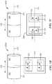
- system 300 Bmay include magnetic field sensor 312 and target 314 .
- Target 314may be a cylindrical or flat rod-shaped target configured to move back and/or forth along line 316 as shown by arrow 318 .
- Target 314may include a magnetic north segment 320 directly adjacent to a magnetic south segment 322 .
- target 314may include additional segments coupled together so that adjacent segments have opposite magnetic poles.
- target 314may have one or more non-magnetic segments adjacent to magnetic segments. The magnetic segments surrounding a non-magnetic segment may have opposite magnetic poles or the same magnetic poles.
- Magnetic field sensor 312may include a first pair 324 of magnetic field sensing elements and a second pair 326 of magnetic field sensing elements. Magnetic field sensor 312 may arranged so that a line drawn from the center of pair 326 to the center of pair 324 is substantially perpendicular to the line of travel 316 of target 314 . Pair 324 may be closer than pair 326 to target 314 . As a result, the magnetic field sensing elements of pair 324 may detect a stronger magnetic field than the magnetic field sensing elements of pair 326 .
- system 300 Cmay include magnetic field sensor 328 and target 314 .
- Target 314may be a cylindrical or flat rod-shaped target configured to move back and/or forth along line 316 as shown by arrow 318 .
- Target 314may include a magnetic north segment 320 directly adjacent to a magnetic south segment 322 .
- target 314may include additional segments coupled together so that adjacent segments have opposite magnetic poles.
- target 314may have one or more non-magnetic segments adjacent to magnetic segments. The magnetic segments surrounding a non-magnetic segment may have opposite magnetic poles or the same magnetic poles.
- Magnetic field sensor 328may include a first pair 330 of magnetic field sensing elements and a second pair 332 of magnetic field sensing elements. Magnetic field sensor 328 may arranged so that a line 334 drawn from the center of pair 330 to the center of pair 332 is substantially parallel to the line of travel 316 of target 314 .
- target 314may move translationally in the directions indicated by arrow 318 .
- the magnetic field it producesalso moves.
- the magnetic field sensing elementswill detect changes in the magnetic field due to its movement. Assume that target 314 is moving in a left-to-right direction on the page.
- Magnetic field sensing element pair 330may detect a particular level or a particular change in the magnetic field before magnetic field sensing element pair 332 does.
- an output signal from magnetic field sensing element pair 330may reflect the particular change or level before an output signal from magnetic field sensing element pair 332 does.
- phase differencethere may be a phase difference between the output signals of the magnetic field sensing elements of pair 330 and the magnetic field sensing elements of pair 332 .
- This phase differencemay be used to detect speed of rotation, direction of rotation, position of target 314 , etc.
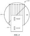
- system 200 ′′may include magnetic field sensor 202 and target 240 arranged so that magnetic field sensor 202 overlaps a flat surface 402 of target 202 .
- magnetic field sensormay be offset from the center of target 240 .
- system 500may include a magnetic field sensor 502 , which may be the same as or similar to magnetic field sensor 202 .
- Magnetic field sensor 502may be placed adjacent to target 504 to detect a magnetic field produced by target 504 .
- Target 504may comprise four quadrants 506 - 512 .
- Each adjacent quadrantmay have opposite magnetic polarities.
- quadrant 506 and 508may be adjacent because they share an edge 514 .
- quadrant 506may have a south polarity and quadrant 508 may have a north polarity.
- Quadrant 508 and 512may be adjacent because they share an edge 516 .
- quadrant 512may have a south polarity and quadrant 508 may have a north polarity.
- Quadrant 510may have a north polarity and share edges with south polarity quadrants 506 and 512 .
- the four quadrants 506 - 512may produce a magnetic field with a direction, in part, that is substantially parallel to the top surface of target 504 as shown, for example, by magnetic field lines 520 .
- Magnetic field sensor 502may be offset from the center of target 504 to detect the magnetic field produced by target 504 as target 504 rotates. In another embodiment, magnetic field sensor 502 may be positioned adjacent to the circumference of target 504 .
- the magnetic field sensormay be centered in position 602 over target 504 , or may be offset, as shown by positions 604 .
- the magnetic field sensormay have two (or more) pairs or sets of magnetic field sensing elements. (See set 212 and set 218 in FIG. 2 ).
- one set of magnetic field sensing elementsmay be positioned closer to the center of target 504 at, for example, position 602 .
- the other set of magnetic field sensing elementsmay be further offset from the center of target 504 at, for example, one of the positions 604 . Separation of the sets of magnetic field sensing elements may result in one set detecting a stronger magnetic field from target 504 and the other set detecting a weaker magnetic field from target 504 .
- the difference in detected field strengthmay be utilized to reject stray magnetic fields, as described above.
- system 700may include magnetic field sensor 202 and target 702 .
- Target 702may be the same as or similar to target 204 or 504 .
- System 700may also include a substrate 704 , which may be a semiconductor substrate, and which may support processing circuit 706 (e.g. processing circuit 706 may be formed in and/or on substrate 704 ).
- Substrate 704may also support magnetic field sensor 202 and magnetic field sensing elements 214 , 216 , 220 , 222 .
- Processing circuit 706may include circuitry to receive signals from magnetic field sensing elements 214 , 216 , 220 , 222 , which represent detection of magnetic field 206 , and may calculate an angle of rotation of magnetic field 206 , a speed of rotation of magnetic field 206 , etc. To perform the calculation, processing circuit 706 may include custom circuitry and/or processor executing software or firmware code that calculates the angle of the magnetic field. Processing circuit 706 may also generate an output signal 708 representing the computed angle, speed, etc.
- Immunity to stray field 210may be accomplished by utilizing the varying levels of signal intensity from the magnetic field sensing elements. As noted above, magnetic field sensing elements 220 and 222 may detect a stronger magnetic field 206 than magnetic field sensing elements 214 and 216 detect, because magnetic field sensing elements 220 and 222 may be closer to target 702 .
- H1yis the output signal of magnetic field sensing element 216
- H1xis the output signal of magnetic field sensing element 214
- H2yis the output of magnetic field sensing element 222
- H2xis the output of magnetic field sensing element 222
- Ais a scalar sensitivity factor of the magnetic field sensing elements
- B 1is magnetic field 206
- B strayis stray magnetic field 210
- kis a scaling factor representing the difference in magnetic field strength as detected by set 212 and set
- Processing circuit 706may provide the signal ⁇ B as output signal 708 .
Landscapes
- Physics & Mathematics (AREA)
- General Physics & Mathematics (AREA)
- Condensed Matter Physics & Semiconductors (AREA)
- Measuring Magnetic Variables (AREA)
- Transmission And Conversion Of Sensor Element Output (AREA)
Abstract
Description
H1y=AB1sin θB+ABstraysin θstray (1)
H1x=AB1cos θB+ABstraycos θstray (2)
H2y=AkB1sin θB+ABstraysin θstray (3)
H2x=AkB1cos θB+ABstraycos θstray (4)
In the equations above, H1y is the output signal of magnetic
Hydiff=(1−k)AB1sin θB (5)
Hxdiff=(1−k)AB1cos θB (6)
The angle of rotation of the magnetic field can be calculated with the following formula:
Claims (22)
Priority Applications (5)
| Application Number | Priority Date | Filing Date | Title |
|---|---|---|---|
| US15/909,208US10866117B2 (en) | 2018-03-01 | 2018-03-01 | Magnetic field influence during rotation movement of magnetic target |
| EP19706847.1AEP3735569B1 (en) | 2018-03-01 | 2019-02-07 | Magnetic field influence during rotation movement of magnetic target |
| PCT/US2019/017012WO2019168645A1 (en) | 2018-03-01 | 2019-02-07 | Magnetic field influence during rotation movement of magnetic target |
| JP2020542581AJP7208246B2 (en) | 2018-03-01 | 2019-02-07 | Magnetic field influence during rotational motion of a magnetic target |
| US17/092,664US11313700B2 (en) | 2018-03-01 | 2020-11-09 | Magnetic field influence during rotation movement of magnetic target |
Applications Claiming Priority (1)
| Application Number | Priority Date | Filing Date | Title |
|---|---|---|---|
| US15/909,208US10866117B2 (en) | 2018-03-01 | 2018-03-01 | Magnetic field influence during rotation movement of magnetic target |
Related Child Applications (1)
| Application Number | Title | Priority Date | Filing Date |
|---|---|---|---|
| US17/092,664DivisionUS11313700B2 (en) | 2018-03-01 | 2020-11-09 | Magnetic field influence during rotation movement of magnetic target |
Publications (2)
| Publication Number | Publication Date |
|---|---|
| US20190271568A1 US20190271568A1 (en) | 2019-09-05 |
| US10866117B2true US10866117B2 (en) | 2020-12-15 |
Family
ID=65516783
Family Applications (2)
| Application Number | Title | Priority Date | Filing Date |
|---|---|---|---|
| US15/909,208Active2038-07-19US10866117B2 (en) | 2018-03-01 | 2018-03-01 | Magnetic field influence during rotation movement of magnetic target |
| US17/092,664ActiveUS11313700B2 (en) | 2018-03-01 | 2020-11-09 | Magnetic field influence during rotation movement of magnetic target |
Family Applications After (1)
| Application Number | Title | Priority Date | Filing Date |
|---|---|---|---|
| US17/092,664ActiveUS11313700B2 (en) | 2018-03-01 | 2020-11-09 | Magnetic field influence during rotation movement of magnetic target |
Country Status (4)
| Country | Link |
|---|---|
| US (2) | US10866117B2 (en) |
| EP (1) | EP3735569B1 (en) |
| JP (1) | JP7208246B2 (en) |
| WO (1) | WO2019168645A1 (en) |
Cited By (5)
| Publication number | Priority date | Publication date | Assignee | Title |
|---|---|---|---|---|
| US11448713B1 (en) | 2021-07-13 | 2022-09-20 | Allegro Microsystems, Llc | Angle sensor |
| US20220349914A1 (en)* | 2021-04-28 | 2022-11-03 | Hyundai Mobis Co., Ltd. | Wheel speed sensor for vehicle |
| US11493361B2 (en) | 2021-02-26 | 2022-11-08 | Allegro Microsystems, Llc | Stray field immune coil-activated sensor |
| US11953395B2 (en) | 2022-03-18 | 2024-04-09 | Allegro Microsystems, Llc | Magnetic field differential linear torque sensor |
| US12416692B2 (en) | 2020-09-09 | 2025-09-16 | Allegro Microsystems, Llc | Stray field immune angle sensor |
Families Citing this family (7)
| Publication number | Priority date | Publication date | Assignee | Title |
|---|---|---|---|---|
| DE102016009209B3 (en)* | 2016-08-01 | 2017-10-19 | Tdk-Micronas Gmbh | measuring system |
| DE102017128869B3 (en)* | 2017-12-05 | 2019-05-29 | Infineon Technologies Ag | Magnetic angle sensor arrangement and method for estimating a rotation angle |
| US10866117B2 (en) | 2018-03-01 | 2020-12-15 | Allegro Microsystems, Llc | Magnetic field influence during rotation movement of magnetic target |
| FR3082615B1 (en)* | 2018-06-15 | 2020-10-16 | Electricfil Automotive | METHOD OF DETERMINING A RELATIVE ANGULAR POSITION BETWEEN TWO PIECES |
| US11371824B2 (en)* | 2019-11-21 | 2022-06-28 | Infineon Technologies Ag | Stray field robust out of shaft angle sensor and measurement system |
| US11604058B2 (en) | 2020-02-25 | 2023-03-14 | Allegro Microsystems, Llc | Reducing stray magnetic field effect on an angle sensor |
| US11733316B2 (en)* | 2020-12-14 | 2023-08-22 | Allegro Microsystems, Llc | Position sensor having harmonic distortion compensation |
Citations (390)
| Publication number | Priority date | Publication date | Assignee | Title |
|---|---|---|---|---|
| US3195043A (en) | 1961-05-19 | 1965-07-13 | Westinghouse Electric Corp | Hall effect proximity transducer |
| US3281628A (en) | 1964-08-14 | 1966-10-25 | Telefunken Patent | Automated semiconductor device method and structure |
| US3607528A (en) | 1968-02-08 | 1971-09-21 | James S Gassaway | Magnetic memory members and methods of making the same |
| US3661061A (en) | 1969-05-05 | 1972-05-09 | Atomic Energy Commission | Picture position finder |
| US3728786A (en) | 1970-11-16 | 1973-04-24 | Crouzet Sa | Method of manufacture of a permanent-magnetized rotor for a synchronous motor |
| DE2518054A1 (en) | 1975-04-23 | 1976-11-04 | Siemens Ag | Detector for linear motion or direction of rotation - with hysteresis switching stage to detect direction of motion has differential stage output in series with hysteresis stage |
| US4048670A (en) | 1975-06-30 | 1977-09-13 | Sprague Electric Company | Stress-free hall-cell package |
| US4079360A (en) | 1974-07-26 | 1978-03-14 | Sony Corporation | Magnetic field sensing apparatus |
| US4188605A (en) | 1978-07-21 | 1980-02-12 | Stout Glenn M | Encapsulated Hall effect device |
| US4204317A (en) | 1977-11-18 | 1980-05-27 | The Arnold Engineering Company | Method of making a lead frame |
| US4236832A (en) | 1977-06-29 | 1980-12-02 | Tokyo Shibaura Denki Kabushiki Kaisha | Strain insensitive integrated circuit resistor pair |
| US4283643A (en) | 1979-05-25 | 1981-08-11 | Electric Power Research Institute, Inc. | Hall sensing apparatus |
| US4315523A (en) | 1980-03-06 | 1982-02-16 | American Flow Systems, Inc. | Electronically controlled flow meter and flow control system |
| US4438347A (en) | 1980-08-13 | 1984-03-20 | Siemens Aktiengesellschaft | Device for changing the electrical circuit configuration of integrated semiconductor circuits |
| US4490674A (en) | 1981-11-18 | 1984-12-25 | Nippon Electric Co., Ltd. | Rotational angle detection device having two magnetoresistive sensing elements |
| US4573258A (en) | 1984-01-18 | 1986-03-04 | Atsugi Motor Parts Co., Ltd. | Method of manufacturing motor |
| JPS6148777A (en) | 1984-08-16 | 1986-03-10 | エルゲーツエツト・ランデイス・ウント・ギール・ツーク・アクチエンゲゼルシヤフト | Compensator for variation of conversion coefficient of magnetic field sensor |
| US4614111A (en) | 1985-02-15 | 1986-09-30 | Wolff George D | Position sensor for fuel injection apparatus |
| US4649796A (en) | 1986-06-18 | 1987-03-17 | The United States Of America As Represented By The Secretary Of The Army | Method and apparatus for setting a projectile fuze during muzzle exit |
| US4670715A (en) | 1983-01-28 | 1987-06-02 | Caterpillar Inc. | Frictionally supported gear tooth sensor with self-adjusting air gap |
| US4719419A (en) | 1985-07-15 | 1988-01-12 | Harris Graphics Corporation | Apparatus for detecting a rotary position of a shaft |
| US4733455A (en) | 1985-08-07 | 1988-03-29 | Victor Company Of Japan, Limited | Method of manufacturing a magnetic head with an MR element |
| JPS6384176A (en) | 1986-09-29 | 1988-04-14 | Toshiba Corp | Magnetic field convergence type Hall element and its manufacturing method |
| US4745363A (en) | 1986-07-16 | 1988-05-17 | North American Philips Corporation | Non-oriented direct coupled gear tooth sensor using a Hall cell |
| US4746859A (en) | 1986-12-22 | 1988-05-24 | Sundstrand Corporation | Power and temperature independent magnetic position sensor for a rotor |
| US4758943A (en) | 1985-04-03 | 1988-07-19 | Hightech Network Ab | Method and an apparatus for automatically tuning a process regulator |
| US4760285A (en) | 1987-03-30 | 1988-07-26 | Honeywell Inc. | Hall effect device with epitaxal layer resistive means for providing temperature independent sensitivity |
| US4769344A (en) | 1984-06-04 | 1988-09-06 | Mitsubishi Denki Kabushiki Kaisha | Method of resin encapsulating a semiconductor device |
| US4772929A (en) | 1987-01-09 | 1988-09-20 | Sprague Electric Company | Hall sensor with integrated pole pieces |
| JPS63263782A (en) | 1987-04-22 | 1988-10-31 | Hitachi Ltd | magnetoelectric conversion element |
| EP0289414A2 (en) | 1987-04-28 | 1988-11-02 | Commissariat A L'energie Atomique | Method and device for the digitization and linearization of a quasi-sinusoidal sensor |
| WO1988009026A1 (en) | 1987-05-15 | 1988-11-17 | SSD Limited | Improvements relating to rotary encoders |
| US4789826A (en) | 1987-03-19 | 1988-12-06 | Ampex Corporation | System for sensing the angular position of a rotatable member using a hall effect transducer |
| JPS63300911A (en) | 1987-05-30 | 1988-12-08 | Yaskawa Electric Mfg Co Ltd | Multi-rotation absolute value encoder |
| US4796354A (en) | 1986-03-19 | 1989-01-10 | Honda Giken Kogyo Kabushiki Kaisha | Method of manufacturing a position sensor for detecting angular position |
| US4823075A (en) | 1987-10-13 | 1989-04-18 | General Electric Company | Current sensor using hall-effect device with feedback |
| US4833406A (en) | 1986-04-17 | 1989-05-23 | Household Commercial Financial Services Inc. | Temperature compensated Hall-effect sensor apparatus |
| US4893027A (en) | 1986-09-25 | 1990-01-09 | Gebhard Balluff Fabrik Feinmechanischer Erzeugnisse Gmbh & Co. | Proximity switch insensitive to interference fields |
| EP0357013A2 (en) | 1988-09-02 | 1990-03-07 | Honeywell Inc. | Magnetic field measuring circuit |
| US4908685A (en) | 1985-05-10 | 1990-03-13 | Asahi Kasei Kogyo Kabushiki Kaisha | Magnetoelectric transducer |
| US4910861A (en) | 1988-10-07 | 1990-03-27 | Emerson Electric Co. | Method of manufacturing retention structure for electric motor rotor magnets |
| EP0361456A2 (en) | 1988-09-30 | 1990-04-04 | Murata Manufacturing Co., Ltd. | Magnetic sensor |
| JPH02116753A (en) | 1988-10-26 | 1990-05-01 | Mitsubishi Electric Corp | Rotation direction detection device |
| US4935698A (en) | 1989-03-03 | 1990-06-19 | Sprague Electric Company | Sensor having dual Hall IC, pole piece and magnet |
| US4970411A (en) | 1988-04-21 | 1990-11-13 | Lgz Landis & Gyr Zug Ag | Arrangement for improving the longterm stability of a Hall element |
| US4983916A (en) | 1988-01-26 | 1991-01-08 | Yamaha Corporation | Compact magnetic encoder |
| JPH0329817A (en) | 1989-06-28 | 1991-02-07 | Fanuc Ltd | Wireless manual encoder |
| US5012322A (en) | 1987-05-18 | 1991-04-30 | Allegro Microsystems, Inc. | Semiconductor die and mounting assembly |
| US5021493A (en) | 1990-03-21 | 1991-06-04 | The Goodyear Tire & Rubber Company | Rubber composition and tire with component(s) thereof |
| US5028868A (en) | 1988-10-11 | 1991-07-02 | Mitsubishi Denki K.K. | Hall effect type sensing device and magnetic circuit device for a hall effect type sensor |
| US5045920A (en) | 1990-06-28 | 1991-09-03 | Allegro Microsystems, Inc. | Dual-Hall ferrous-article-proximity sensor |
| US5078944A (en) | 1987-11-02 | 1992-01-07 | Matsushita Electric Industrial Co., Ltd. | Method for making permanent magnet type demagnetizing head |
| US5084289A (en) | 1989-02-01 | 1992-01-28 | Korea Food Research Institute | Method for the inhibition of oxidation of edible oils utilizing a fat soluble anti-oxidant and a water soluble anti-oxdant in a reverse micelle system |
| DE4031560A1 (en) | 1990-10-05 | 1992-04-09 | Dieter Prof Dr Ing Seitzer | Integrated current sensor for current limiting and measuring - has components sensitive to magnetic field and excitation paths formed by film technique on substrate |
| US5121289A (en) | 1990-01-31 | 1992-06-09 | Honeywell Inc. | Encapsulatable sensor assembly |
| US5137677A (en) | 1989-03-09 | 1992-08-11 | Mitsubishi Denki K.K. | Hall sensor device and method of producing the same |
| US5139973A (en) | 1990-12-17 | 1992-08-18 | Allegro Microsystems, Inc. | Method for making a semiconductor package with the distance between a lead frame die pad and heat spreader determined by the thickness of an intermediary insulating sheet |
| EP0504583A1 (en) | 1991-02-18 | 1992-09-23 | ITT Automotive Europe GmbH | Method of and arrangement for detecting a direction of movement, especially a direction of rotation |
| US5167896A (en) | 1991-01-16 | 1992-12-01 | Kyowa Electric & Chemical Co., Ltd. | Method of manufacturing a front cabinet for use with a display |
| US5168244A (en) | 1991-06-19 | 1992-12-01 | Nec Corporation | Electric circuit fabricated from magneto-resistive elements and active circuit elements |
| US5185919A (en) | 1990-11-19 | 1993-02-16 | Ford Motor Company | Method of manufacturing a molded fuel injector |
| US5196794A (en) | 1989-03-14 | 1993-03-23 | Mitsubishi Denki K.K. | Hall-effect sensor with integrally molded frame, magnet, flux guide and insulative film |
| US5210493A (en) | 1992-02-27 | 1993-05-11 | General Motors Corporation | Method for embedding wires within a powder metal core and sensor assembly produced by such a method |
| US5216405A (en) | 1991-01-14 | 1993-06-01 | General Motors Corporation | Package for the magnetic field sensitive device |
| US5220207A (en) | 1991-09-03 | 1993-06-15 | Allegro Microsystems, Inc. | Load current monitor for MOS driver |
| WO1993012403A1 (en) | 1991-12-19 | 1993-06-24 | Swf Auto-Electric Gmbh | Sensor of the speed of rotation, in particular of toothed wheels |
| US5244834A (en) | 1989-05-10 | 1993-09-14 | Nippondenso Co., Ltd. | Semiconductor device |
| US5247202A (en) | 1991-10-09 | 1993-09-21 | Landis & Gyr Betriebs Ag | Plurality of arrangements each including an ic magnetic field sensor and two ferromagnetic field concentrators, and a procedure for incorporating each arrangement into a package |
| US5247278A (en) | 1991-11-26 | 1993-09-21 | Honeywell Inc. | Magnetic field sensing device |
| US5250925A (en) | 1992-05-11 | 1993-10-05 | General Motors Corporation | Package for speed sensing device having minimum air gap |
| US5286426A (en) | 1992-04-01 | 1994-02-15 | Allegro Microsystems, Inc. | Assembling a lead frame between a pair of molding cavity plates |
| US5289344A (en) | 1992-10-08 | 1994-02-22 | Allegro Microsystems Inc. | Integrated-circuit lead-frame package with failure-resistant ground-lead and heat-sink means |
| CH683469A5 (en) | 1992-07-03 | 1994-03-15 | Landis & Gyr Business Support | Semiconductor wafer contg. magnetic field sensor - is installed between pole shoes of laminated ferromagnetic magnetic flux concentrator to measure magnetic field in proximity |
| WO1994008203A1 (en) | 1992-09-29 | 1994-04-14 | Honeywell Inc. | Asymmetrical magnetic position detector |
| US5329416A (en) | 1993-07-06 | 1994-07-12 | Alliedsignal Inc. | Active broadband magnetic flux rate feedback sensing arrangement |
| US5331478A (en) | 1992-10-07 | 1994-07-19 | Silicon Systems, Inc. | Magnetoresistive head amplifier |
| US5332965A (en) | 1992-06-22 | 1994-07-26 | Durakool Incorporated | Contactless linear angular position sensor having an adjustable flux concentrator for sensitivity adjustment and temperature compensation |
| US5332956A (en) | 1991-11-08 | 1994-07-26 | Gold Star Co., Ltd. | Motor rotation controlling device |
| JPH06273437A (en) | 1993-03-22 | 1994-09-30 | Yazaki Corp | Rotation detection apparatus |
| GB2276727A (en) | 1993-04-01 | 1994-10-05 | Rolls Royce & Ass | Magnetoresistive magnetometer |
| EP0629834A1 (en) | 1992-03-02 | 1994-12-21 | Seiko Epson Corporation | Displacement sensor |
| US5412255A (en) | 1991-05-07 | 1995-05-02 | Vdo Adolf Schindling Ag | Switch device suitable for use in automotive vehicles |
| US5414355A (en) | 1994-03-03 | 1995-05-09 | Honeywell Inc. | Magnet carrier disposed within an outer housing |
| US5424558A (en) | 1993-05-17 | 1995-06-13 | High Yield Technology, Inc. | Apparatus and a method for dynamically tuning a particle sensor in response to varying process conditions |
| WO1995018982A1 (en) | 1994-01-11 | 1995-07-13 | Honeywell Inc. | Sensor with magnetoresistive elements |
| US5434105A (en) | 1994-03-04 | 1995-07-18 | National Semiconductor Corporation | Process for attaching a lead frame to a heat sink using a glob-top encapsulation |
| US5453727A (en) | 1991-07-16 | 1995-09-26 | Asahi Kasai Kogyo Kabushiki Kaisha | Semiconductor sensors and method for fabricating the same |
| EP0680103A1 (en) | 1994-04-25 | 1995-11-02 | General Motors Corporation | Magnetic field sensor |
| US5469058A (en) | 1992-12-30 | 1995-11-21 | Dunnam; Curt | Feedback enhanced sensor, alternating magnetic field detector |
| US5479695A (en) | 1991-05-02 | 1996-01-02 | At&T Corp. | Method of making a multilayer monolithic magnetic component |
| US5486759A (en) | 1992-10-21 | 1996-01-23 | Robert Bosch Gmbh | Device for detecting the movement of a movable component and signalling the detected movement over a single line |
| US5488294A (en) | 1995-01-18 | 1996-01-30 | Honeywell Inc. | Magnetic sensor with means for retaining a magnet at a precise calibrated position |
| WO1996002849A1 (en) | 1994-07-19 | 1996-02-01 | Honeywell Inc. | Temperature compensation circuit for a hall effect element |
| US5491633A (en) | 1991-05-20 | 1996-02-13 | General Motors Corporation | Position sensor for electromechanical suspension |
| US5497081A (en) | 1992-06-22 | 1996-03-05 | Durakool Incorporated | Mechanically adjustable linear-output angular position sensor |
| US5500589A (en) | 1995-01-18 | 1996-03-19 | Honeywell Inc. | Method for calibrating a sensor by moving a magnet while monitoring an output signal from a magnetically sensitive component |
| US5500994A (en) | 1993-12-30 | 1996-03-26 | Mabuchi Motor Co., Ltd. | Method of manufacturing a rotor |
| JPH0897486A (en) | 1994-09-22 | 1996-04-12 | Hitachi Cable Ltd | Hall sensor |
| US5521501A (en) | 1993-06-09 | 1996-05-28 | Institut Fuer Mikrostrukturtechnologie Und Optoelektronik E.V. | Magnetic field sensor constructed from a remagnetization line and one magnetoresistive resistor or a plurality of magnetoresistive resistors |
| US5551146A (en) | 1991-07-08 | 1996-09-03 | Murata Manufacturing Co., Ltd. | Method of manufacturing a solid inductor |
| US5552706A (en) | 1992-12-29 | 1996-09-03 | Eastman Kodak Company | Magnetoresistive magnetic field sensor divided into a plurality of subelements which are arrayed spatially in series but are connected electrically in parallel |
| US5572058A (en) | 1995-07-17 | 1996-11-05 | Honeywell Inc. | Hall effect device formed in an epitaxial layer of silicon for sensing magnetic fields parallel to the epitaxial layer |
| US5581179A (en) | 1995-05-31 | 1996-12-03 | Allegro Microsystems, Inc. | Hall-effect ferrous-article-proximity sensor assembly |
| US5581170A (en) | 1994-12-12 | 1996-12-03 | Unitrode Corporation | Battery protector |
| US5621319A (en) | 1995-12-08 | 1997-04-15 | Allegro Microsystems, Inc. | Chopped hall sensor with synchronously chopped sample-and-hold circuit |
| DE19539458A1 (en) | 1995-10-24 | 1997-04-30 | Bosch Gmbh Robert | Self-testing Hall sensor, e.g for vehicle steering angle monitor |
| US5627315A (en) | 1995-04-18 | 1997-05-06 | Honeywell Inc. | Accelerometer with a cantilever beam formed as part of the housing structure |
| US5631557A (en) | 1996-02-16 | 1997-05-20 | Honeywell Inc. | Magnetic sensor with encapsulated magnetically sensitive component and magnet |
| US5640090A (en) | 1995-01-31 | 1997-06-17 | Mitsumi Electric Company, Ltd. | Sensor IC |
| JPH09166612A (en) | 1995-12-18 | 1997-06-24 | Nissan Motor Co Ltd | Magnetic sensor |
| FR2748105A1 (en) | 1996-04-25 | 1997-10-31 | Siemens Automotive Sa | Magnetic sensor for use in automobile shaft, wheel rotational measurements. |
| US5691637A (en) | 1992-08-28 | 1997-11-25 | True Position Magnetics, Inc. | Magnetic field position transducer for two or more dimensions |
| US5696790A (en) | 1995-10-04 | 1997-12-09 | Tut Systems, Inc. | Method and apparatus for time dependent data transmission |
| US5712562A (en) | 1995-10-13 | 1998-01-27 | Bently Nevada Corporation | Encapsulated transducer with an alignment plug and method of manufacture |
| US5714102A (en) | 1992-01-02 | 1998-02-03 | International Business Machines Corporation | Method for manufacturing electro-magnetic shield having multiple polymeric layers of differing fill compositions |
| JPH1038988A (en) | 1996-07-30 | 1998-02-13 | Yazaki Corp | Integrated magnetoresistive element circuit |
| US5719496A (en) | 1995-06-07 | 1998-02-17 | Durakool Incorporated | Dual-element proximity sensor for sensing the direction of rotation of a ferrous target wheel |
| DE19634715A1 (en) | 1996-08-28 | 1998-03-05 | Teves Gmbh Alfred | Arrangement for detecting the turning behavior of a wheel |
| US5729128A (en) | 1996-11-22 | 1998-03-17 | Honeywell Inc. | Magnetic sensor with a magnetically sensitive component that is movable during calibration and rigidly attachable to a formed magnet |
| US5757181A (en) | 1992-06-22 | 1998-05-26 | Durakool Incorporated | Electronic circuit for automatically compensating for errors in a sensor with an analog output signal |
| DE19650935A1 (en) | 1996-12-07 | 1998-06-10 | Teves Gmbh Alfred | Method and circuit arrangement for the transmission of speed information and additional data |
| US5781005A (en) | 1995-06-07 | 1998-07-14 | Allegro Microsystems, Inc. | Hall-effect ferromagnetic-article-proximity sensor |
| US5789658A (en) | 1995-10-31 | 1998-08-04 | Siemens Aktiengesellschaft | Adaptation method for correcting tolerances of a transducer wheel |
| US5789915A (en) | 1989-02-17 | 1998-08-04 | Nartron Corporation | Magnetic field energy responsive position sensing apparatus and method |
| US5796249A (en) | 1995-03-23 | 1998-08-18 | Institut Fuer Physikalische Hochtechnologle E.V. | Magnetoresistive angular position sensor and rotation speed sensor |
| US5818222A (en) | 1995-06-07 | 1998-10-06 | The Cherry Corporation | Method for adjusting ferrous article proximity detector |
| US5841276A (en) | 1995-05-12 | 1998-11-24 | Nippondenso Co., Ltd | Magnetic gear rotation sensor |
| US5839185A (en) | 1997-02-26 | 1998-11-24 | Sundstrand Corporation | Method of fabricating a magnetic flux concentrating core |
| JPH10318784A (en) | 1997-05-20 | 1998-12-04 | Matsushita Electric Ind Co Ltd | Rotation detection device |
| JPH10332725A (en) | 1997-04-01 | 1998-12-18 | Denso Corp | Detection signal processing device for rotation sensor |
| US5859387A (en) | 1996-11-29 | 1999-01-12 | Allegro Microsystems, Inc. | Semiconductor device leadframe die attach pad having a raised bond pad |
| EP0898180A2 (en) | 1997-08-19 | 1999-02-24 | Allegro Microsystems Inc. | Package for a magnetic field sensing device |
| JPH1164363A (en) | 1997-08-25 | 1999-03-05 | Aisin Seiki Co Ltd | Rotation detector |
| US5883567A (en) | 1997-10-10 | 1999-03-16 | Analog Devices, Inc. | Packaged integrated circuit with magnetic flux concentrator |
| JPH1174142A (en) | 1997-08-27 | 1999-03-16 | Hitachi Metals Ltd | Device for molding cylindrical resin magnet |
| US5886070A (en) | 1996-07-04 | 1999-03-23 | Aichi Steel Works, Ltd. | Production method for anisotropic resin-bonded magnets |
| US5912556A (en) | 1996-11-06 | 1999-06-15 | Honeywell Inc. | Magnetic sensor with a chip attached to a lead assembly within a cavity at the sensor's sensing face |
| WO1999049322A1 (en) | 1998-03-20 | 1999-09-30 | Continental Teves Ag & Co. Ohg | Sensor system for detecting movements |
| DE19851839A1 (en) | 1998-04-23 | 1999-11-11 | Mitsubishi Electric Corp | Magnetic detector for use with a toothed magnetic material rotating device to determine the angle of rotation |
| US6011770A (en) | 1997-12-10 | 2000-01-04 | Texas Instrumental Incorporated | Method and apparatus for high-order bandpass filter with linearly adjustable bandwidth |
| US6016055A (en) | 1995-02-02 | 2000-01-18 | Siemens Aktiengesellschaft | Device for increasing the magnetic flux density in the vicinity of a hall sensor cooperating with a magnet wheel |
| US6043646A (en) | 1994-08-31 | 2000-03-28 | Siemens Aktiengesellschaft | Proximity switch with magnetic field-sensitive sensor |
| JP2000183241A (en) | 1998-12-21 | 2000-06-30 | Sanyo Electric Co Ltd | Semiconductor device and manufacture thereof |
| US6100754A (en) | 1998-08-03 | 2000-08-08 | Advanced Micro Devices, Inc. | VT reference voltage for extremely low power supply |
| US6136250A (en) | 1998-01-30 | 2000-10-24 | Comair Rotron, Inc. | Apparatus and method of encapsulating motors |
| US6175233B1 (en) | 1996-10-18 | 2001-01-16 | Cts Corporation | Two axis position sensor using sloped magnets to generate a variable magnetic field and hall effect sensors to detect the variable magnetic field |
| US6181036B1 (en) | 1998-06-30 | 2001-01-30 | Ykk Corporation | Rotational angle detector for brushless motor and brushless motor using the detector |
| US6180041B1 (en) | 1992-07-07 | 2001-01-30 | Nippon Seiki K.K. | Process for manufacturing a pointer |
| US6184679B1 (en) | 1995-10-30 | 2001-02-06 | Sentron Ag | Magnetic field sensor comprising two hall elements |
| JP2001043475A (en) | 1999-07-27 | 2001-02-16 | Nsk Ltd | Transmission method of sensor detection signal |
| US6198373B1 (en) | 1997-08-19 | 2001-03-06 | Taiyo Yuden Co., Ltd. | Wire wound electronic component |
| JP2001141738A (en) | 1999-11-18 | 2001-05-25 | Sumitomo Electric Ind Ltd | Rotation sensor and method of manufacturing the same |
| US6242604B1 (en) | 1996-09-30 | 2001-06-05 | Mallinckrodt Inc. | Process for preparing a morphinan derivative |
| US6242905B1 (en) | 1998-04-23 | 2001-06-05 | Siemens Aktiengesellschaft | Method for identifying the direction of rotation of a wheel using hall probes |
| US6246226B1 (en)* | 1996-08-23 | 2001-06-12 | Canon Kabushiki Kaisha | Method and apparatus for detecting tire revolution using magnetic field |
| JP2001165951A (en) | 1999-12-07 | 2001-06-22 | Denso Corp | Rotation sensor detection signal processing device and rotation sensor detection signal output method |
| JP2001165702A (en) | 1999-12-10 | 2001-06-22 | Sumitomo Electric Ind Ltd | Magnetic variable detection sensor |
| DE19961504A1 (en) | 1999-12-20 | 2001-06-28 | Bosch Gmbh Robert | Rotational speed signal error detection method for anti-slip or anti-lock regulation system of vehicle, involves detecting speed change based on specific condition involving pulse width of falling pulses of measurement signal |
| US20010009367A1 (en) | 1999-02-26 | 2001-07-26 | Dieter Seitzer | Sensor device to record speed and motion direction of an object, especially rotational speed and direction of a rotating object |
| US6278269B1 (en) | 1999-03-08 | 2001-08-21 | Allegro Microsystems, Inc. | Magnet structure |
| US6291989B1 (en) | 1999-08-12 | 2001-09-18 | Delphi Technologies, Inc. | Differential magnetic position sensor with adaptive matching for detecting angular position of a toothed target wheel |
| US6297628B1 (en) | 1998-11-17 | 2001-10-02 | Honeywell Inc | Magnetoresistive bridge array |
| US6297627B1 (en) | 1996-01-17 | 2001-10-02 | Allegro Microsystems, Inc. | Detection of passing magnetic articles with a peak-to-peak percentage threshold detector having a forcing circuit and automatic gain control |
| WO2001074139A2 (en) | 2000-04-04 | 2001-10-11 | Honeywell International Inc. | Hall-effect element with integrated offset control and method for operating hall-effect element to reduce null offset |
| US6323642B1 (en) | 1997-01-24 | 2001-11-27 | Diamond Electric Mfg. Co., Ltd. | Detector for determining rotational speed and position for an internal combustion engine |
| US6351506B1 (en) | 1999-04-19 | 2002-02-26 | National Semiconductor Corporation | Switched capacitor filter circuit having reduced offsets and providing offset compensation when used in a closed feedback loop |
| US20020027488A1 (en) | 2000-08-31 | 2002-03-07 | Kambiz Hayat-Dawoodi | Method and system for isolated coupling |
| US6356068B1 (en) | 1997-09-15 | 2002-03-12 | Ams International Ag | Current monitor system and a method for manufacturing it |
| JP2002117500A (en) | 2000-10-05 | 2002-04-19 | Ntt Data Corp | Flight path setting device and recording medium |
| US6392478B1 (en) | 1999-11-23 | 2002-05-21 | U.S. Philips Corporation | Amplification device having an adjustable bandwidth |
| JP2002149013A (en) | 2000-11-06 | 2002-05-22 | Minolta Co Ltd | Image forming apparatus |
| US6436748B1 (en) | 1999-08-31 | 2002-08-20 | Micron Technology, Inc. | Method for fabricating CMOS transistors having matching characteristics and apparatus formed thereby |
| US6437558B2 (en) | 1998-07-31 | 2002-08-20 | Spinix Corporation | Passive solid-state magnetic field sensors and applications therefor |
| US6452381B1 (en) | 1997-11-28 | 2002-09-17 | Denso Corporation | Magnetoresistive type position detecting device |
| JP2002357920A (en) | 2001-05-31 | 2002-12-13 | Nippon Zeon Co Ltd | Developing method and image forming method |
| US6501270B1 (en) | 2000-05-15 | 2002-12-31 | Siemens Vdo Automotive Corporation | Hall effect sensor assembly with cavities for integrated capacitors |
| US20030001563A1 (en) | 2001-06-27 | 2003-01-02 | Turner Jason D. | Rotational velocity and direction sensing system |
| US6525531B2 (en) | 1996-01-17 | 2003-02-25 | Allegro, Microsystems, Inc. | Detection of passing magnetic articles while adapting the detection threshold |
| US20030038675A1 (en) | 2001-08-20 | 2003-02-27 | Gailus Paul H. | Feedback loop with adjustable bandwidth |
| US20030062891A1 (en) | 2001-10-02 | 2003-04-03 | Slates Richard Dale | Multi-coil proximity probe system: apparatus and method |
| US6545332B2 (en) | 2001-01-17 | 2003-04-08 | Siliconware Precision Industries Co., Ltd. | Image sensor of a quad flat package |
| US6545462B2 (en) | 2000-08-21 | 2003-04-08 | Sentron Ag | Sensor for the detection of the direction of a magnetic field having magnetic flux concentrators and hall elements |
| US6545457B2 (en) | 2000-07-07 | 2003-04-08 | Sanken Electric Co., Ltd. | Current detector utilizing hall effect |
| US20030102909A1 (en) | 2000-07-05 | 2003-06-05 | Mario Motz | Amplifier circuit with offset compensation |
| JP2003177171A (en) | 2001-12-11 | 2003-06-27 | Sumitomo Electric Ind Ltd | Magnetic variable sensor and manufacturing method thereof |
| US6590804B1 (en) | 2002-07-16 | 2003-07-08 | Hewlett-Packard Development Company, L.P. | Adjustable current mode differential amplifier |
| US20030151406A1 (en)* | 2002-02-11 | 2003-08-14 | Hong Wan | Magnetic field sensor |
| WO2003069358A2 (en) | 2002-01-31 | 2003-08-21 | Allegro Microsystems, Inc. | Method and apparatus for providing information from a speed and direction sensor |
| US20030173955A1 (en) | 2002-03-18 | 2003-09-18 | Hirofumi Uenoyama | Position determination device using magnetoresistive element |
| DE10210184A1 (en) | 2002-03-07 | 2003-09-18 | Philips Intellectual Property | Magnetic field arrangement for detection of the position and rotational velocity of a rotating element has a coil arrangement for generation of an additional time varying magnetic field to reduce finishing tolerance effects |
| US6653968B1 (en) | 1999-08-06 | 2003-11-25 | Robert Bosch Gmbh | System for generating a signal to superimpose information |
| WO2003107018A1 (en) | 2002-06-18 | 2003-12-24 | 旭化成株式会社 | Current measuring method and current measuring device |
| US6674679B1 (en) | 2002-10-01 | 2004-01-06 | Hewlett-Packard Development Company, L.P. | Adjustable current mode differential amplifier for multiple bias point sensing of MRAM having equi-potential isolation |
| JP2004055932A (en) | 2002-07-22 | 2004-02-19 | Asahi Kasei Corp | Magnetoelectric conversion element and method of manufacturing the same |
| US20040046248A1 (en) | 2002-09-05 | 2004-03-11 | Corning Intellisense Corporation | Microsystem packaging and associated methods |
| JP2004093381A (en) | 2002-08-30 | 2004-03-25 | Toshiba Corp | Radiation detector and radiation detection method |
| WO2004027436A1 (en) | 2002-09-20 | 2004-04-01 | Allegro Microsystems, Inc. | Integrated current sensor |
| US20040062362A1 (en) | 2002-09-18 | 2004-04-01 | Yasuyuki Matsuya | Data communication method, data transmitting apparatus, data receiving apparatus, and data transmission program |
| US20040080314A1 (en) | 2002-10-24 | 2004-04-29 | Mitsubishi Denki Kabushiki Kaisha | Magnetic detection apparatus |
| JP2004152688A (en) | 2002-10-31 | 2004-05-27 | Toshiba Plant Systems & Services Corp | Cable connection part and its insulation method |
| US20040135220A1 (en) | 2002-12-25 | 2004-07-15 | Sanken Electric Co., Ltd. | Noise-proof semiconductor device having a Hall effect element |
| US6768301B1 (en) | 1999-09-09 | 2004-07-27 | Fraunhofer-Gesellschaft Zur Foerderung Der Angewandten Forschung E.V. | Hall sensor array for measuring a magnetic field with offset compensation |
| US6770163B1 (en) | 2000-09-08 | 2004-08-03 | Asm Technology Singapore Pte Ltd | Mold and method for encapsulation of electronic device |
| EP1443332A1 (en) | 2001-11-01 | 2004-08-04 | Asahi Kasei EMD Corporation | Current sensor and current sensor manufacturing method |
| US6781233B2 (en) | 2001-08-28 | 2004-08-24 | Infineon Technologies Ag | Semiconductor device and converter device with an integrated capacitor |
| WO2004072672A1 (en) | 2003-02-11 | 2004-08-26 | Allegro Microsystems, Inc. | Integrated sensor |
| US20040174164A1 (en) | 2003-03-03 | 2004-09-09 | Denso Corporation | Magnetic sensor and method for fabricating the same |
| US20040184196A1 (en) | 2003-03-18 | 2004-09-23 | Jayasekara Wipul P. | Magnetoresistive sensor having a high resistance soft magnetic layer between sensor stack and shield |
| US6798193B2 (en) | 2002-08-14 | 2004-09-28 | Honeywell International Inc. | Calibrated, low-profile magnetic sensor |
| US20040189285A1 (en) | 2003-03-31 | 2004-09-30 | Denso Corporation | Magnetic sensor adjusting method, magnetic sensor adjusting device and magnetic sensor |
| DE10314602A1 (en) | 2003-03-31 | 2004-10-21 | Infineon Technologies Ag | Monolithically integrated differential magnetic field sensor device, has layer of permeable material covering two magnetic field sensor elements, parallel to substrate |
| US6822443B1 (en) | 2000-09-11 | 2004-11-23 | Albany Instruments, Inc. | Sensors and probes for mapping electromagnetic fields |
| US20040252563A1 (en) | 2003-06-12 | 2004-12-16 | Rohm Co., Ltd. | Magnetic record reproducing device |
| JP2004356338A (en) | 2003-05-28 | 2004-12-16 | Res Inst Electric Magnetic Alloys | Thin film magnetic sensor and method of manufacturing the same |
| JP2004357858A (en) | 2003-06-03 | 2004-12-24 | Samii Kk | Attachment/detachment facilitating mechanism for game board |
| US6853178B2 (en) | 2000-06-19 | 2005-02-08 | Texas Instruments Incorporated | Integrated circuit leadframes patterned for measuring the accurate amplitude of changing currents |
| WO2005013363A2 (en) | 2003-07-31 | 2005-02-10 | Siemens Aktiengesellschaft | Circuit arrangement placed on a substrate and method for producing the same |
| US6896407B2 (en) | 2001-11-05 | 2005-05-24 | Yamatake Corporation | Temperature information detecting device for angle sensor and position detecting device |
| US6902951B2 (en) | 2002-10-29 | 2005-06-07 | Infineon Technologies Ag | Electronic device configured as a multichip module, leadframe, panel with leadframe positions, and method for producing the electronic device |
| US20050120782A1 (en) | 2003-12-08 | 2005-06-09 | Kokusan Denki Co., Ltd. | Engine rotation information detection device |
| US6917321B1 (en) | 2000-05-21 | 2005-07-12 | Analog Devices, Inc. | Method and apparatus for use in switched capacitor systems |
| US20050167790A1 (en) | 2003-12-31 | 2005-08-04 | Carsem (M) Sdn.Bhd. | Integrated circuit package with transparent encapsulant and method for making thereof |
| US20050179429A1 (en) | 2002-04-18 | 2005-08-18 | Continental Teves, Ag & Co Ohg | Method and device for the detection of local displacements and rotations |
| EP1580560A1 (en) | 2004-03-24 | 2005-09-28 | Aisin Seiki Kabushiki Kaisha | Rotation-detecting-apparatus |
| US20050225318A1 (en) | 2004-04-08 | 2005-10-13 | Bailey James M | Methods and apparatus for vibration detection |
| JP2005337866A (en) | 2004-05-26 | 2005-12-08 | Asahi Kasei Corp | Magnetic detector and semiconductor package |
| JP2005345302A (en) | 2004-06-03 | 2005-12-15 | Denso Corp | Rotation detection apparatus and method for manufacturing rotation detection apparatus |
| JP2006003096A (en) | 2004-06-15 | 2006-01-05 | Mitsubishi Electric Corp | Magnetic detector |
| US20060028204A1 (en) | 2004-08-06 | 2006-02-09 | Denso Corporation | Rotation angle detector |
| US20060038559A1 (en) | 2004-08-20 | 2006-02-23 | Honeywell International, Inc. | Magnetically biased eddy current sensor |
| EP1637898A1 (en) | 2004-09-16 | 2006-03-22 | Liaisons Electroniques-Mecaniques Lem S.A. | Continuously calibrated magnetic field sensor |
| US20060068237A1 (en) | 2004-09-29 | 2006-03-30 | Murphy Michael W | Integrated current sensors for a fuel cell stack |
| US7023205B1 (en) | 2000-08-01 | 2006-04-04 | General Dynamics Advanced Information Systems, Inc. | Eddy current sensor capable of sensing through a conductive barrier |
| US7031170B2 (en) | 2001-09-28 | 2006-04-18 | Infineon Technologies Ag | Electronic device having a plastic housing and components of a height-structured metallic leadframe and methods for the production of the electronic device |
| US7038448B2 (en) | 2001-05-25 | 2006-05-02 | Sentron Ag | Magnetic field sensor |
| US20060097715A1 (en) | 2004-10-28 | 2006-05-11 | Denso Corporation | Vertical Hall device and method for adjusting offset voltage of vertical Hall device |
| EP1662353A1 (en) | 2004-11-25 | 2006-05-31 | Alcatel | Method and device for recognition of the direction of travel |
| US20060125473A1 (en) | 2002-10-07 | 2006-06-15 | Didier Frachon | Variable reluctance position sensor |
| EP1679524A1 (en) | 2005-01-11 | 2006-07-12 | Ecole Polytechnique Federale De Lausanne Epfl - Sti - Imm - Lmis3 | Hall sensor and method of operating a Hall sensor |
| WO2006083479A1 (en) | 2005-02-04 | 2006-08-10 | Allegro Microsystems, Inc. | Integrated sensor having a magnetic flux concentrator |
| US20060181263A1 (en) | 2003-08-26 | 2006-08-17 | Allegro Microsystems, Inc. | Current sensor |
| US7112955B2 (en) | 2001-08-23 | 2006-09-26 | Koninklijke Philips Electronics N.V. | Magnetic sensing device including a magnetoresistive sensor and a supporting magnet |
| US7112957B2 (en) | 2004-06-16 | 2006-09-26 | Honeywell International Inc. | GMR sensor with flux concentrators |
| US20060261801A1 (en) | 2005-05-20 | 2006-11-23 | Honeywell International Inc. | Magnetoresistive sensor |
| JP2007012582A (en) | 2005-05-30 | 2007-01-18 | Internatl Superconductivity Technology Center | RE oxide superconducting wire joining method |
| US7184876B2 (en) | 2004-06-18 | 2007-02-27 | Siemens Vdo Automotive | Device and process for determining the position of an engine |
| US7190784B2 (en) | 2000-12-29 | 2007-03-13 | Legerity, Inc. | Method and apparatus for adaptive DC level control |
| US7193412B2 (en) | 2004-03-24 | 2007-03-20 | Stoneridge Control Devices, Inc. | Target activated sensor |
| US7199579B2 (en) | 2004-03-08 | 2007-04-03 | Allegro Microsystems, Inc. | Proximity detector |
| US20070110199A1 (en) | 2005-11-15 | 2007-05-17 | Afshin Momtaz | Receive equalizer with adaptive loops |
| JP2007218799A (en) | 2006-02-17 | 2007-08-30 | Asahi Kasei Electronics Co Ltd | Semiconductor magnetoresistive element and magnetic sensor module using the same |
| US7269992B2 (en) | 2005-06-15 | 2007-09-18 | Honeywell International Inc. | Magnet orientation and calibration for small package turbocharger speed sensor |
| US7285952B1 (en) | 2006-02-23 | 2007-10-23 | Denso Corporation | Rotation angle detecting device |
| EP1850143A1 (en) | 2005-02-08 | 2007-10-31 | Rohm Co., Ltd. | Magnetic sensor circuit and portable terminal provided with such magnetic sensor circuit |
| US7292095B2 (en) | 2006-01-26 | 2007-11-06 | Texas Instruments Incorporated | Notch filter for ripple reduction in chopper stabilized amplifiers |
| US7295000B2 (en) | 2004-05-26 | 2007-11-13 | Infineon Technologies Ag | Method for detecting disturbances when determining the rotational speed of a rotor and evaluation circuit |
| WO2007138508A1 (en) | 2006-05-30 | 2007-12-06 | Koninklijke Philips Electronics N. V. | Sensor device with adaptive field compensation |
| US20070285089A1 (en) | 2006-03-31 | 2007-12-13 | Daihen Corporation | Current detection printed board, voltage detection printed board, current/voltage detection printed board, current/voltage detector, current detector and voltage detector |
| US20070290682A1 (en) | 2006-01-13 | 2007-12-20 | Denso Corporation | Magnetic sensor and method for detecting magnetic field |
| US7319319B2 (en) | 2001-10-30 | 2008-01-15 | Tt Electronics Technology Limited | Sensing apparatus and method |
| US20080013298A1 (en) | 2006-07-14 | 2008-01-17 | Nirmal Sharma | Methods and apparatus for passive attachment of components for integrated circuits |
| US20080012558A1 (en) | 2006-07-12 | 2008-01-17 | Werner Rossler | Magnetic field sensor device |
| US7323780B2 (en) | 2005-11-10 | 2008-01-29 | International Business Machines Corporation | Electrical interconnection structure formation |
| US7323870B2 (en) | 2005-02-23 | 2008-01-29 | Infineon Technologies Ag | Magnetoresistive sensor element and method of assembling magnetic field sensor elements with on-wafer functional test |
| US7325175B2 (en) | 2005-05-04 | 2008-01-29 | Broadcom Corporation | Phase adjust using relative error |
| DE102006037226A1 (en) | 2006-08-09 | 2008-02-14 | Fraunhofer-Gesellschaft zur Förderung der angewandten Forschung e.V. | Calibratable magnetic 3D-point sensor during measuring operation |
| US7345468B2 (en) | 2004-03-02 | 2008-03-18 | Denso Corporation | Detection signal processing circuit and detection signal processing apparatus for a rotation sensor |
| US7355388B2 (en) | 2005-04-21 | 2008-04-08 | Denso Corporation | Rotation detecting device using magnetic sensor |
| US7362094B2 (en) | 2006-01-17 | 2008-04-22 | Allegro Microsystems, Inc. | Methods and apparatus for magnetic article detection |
| US7361531B2 (en) | 2005-11-01 | 2008-04-22 | Allegro Microsystems, Inc. | Methods and apparatus for Flip-Chip-On-Lead semiconductor package |
| WO2008048379A1 (en) | 2006-10-19 | 2008-04-24 | Allegro Microsystems, Inc. | Chopped hall effect sensor |
| US7365530B2 (en) | 2004-04-08 | 2008-04-29 | Allegro Microsystems, Inc. | Method and apparatus for vibration detection |
| US20080116884A1 (en) | 2004-03-11 | 2008-05-22 | Rasmus Rettig | Magnet Sensor Arrangement |
| US7385394B2 (en) | 2005-06-15 | 2008-06-10 | Infineon Technologies Ag | Integrated magnetic sensor component |
| FR2909756A1 (en) | 2006-12-06 | 2008-06-13 | Bosch Gmbh Robert | Movement detecting system i.e. movement sensor, for wheel of motor vehicle, has high frequency transmission circuit linked to electronic reading circuit for receiving reading signal and sending high frequency signal to transmitting antenna |
| US20080237818A1 (en) | 2007-03-29 | 2008-10-02 | Engel Raymond W | Methods and apparatus for multi-stage molding of integrated circuit package |
| DE102007018238A1 (en) | 2007-04-18 | 2008-10-23 | Robert Bosch Gmbh | Device for detecting the rotational speed of a rotatable part |
| JP2008264569A (en) | 1997-10-08 | 2008-11-06 | Kaneka Corp | Balloon catheter and manufacturing method for it |
| WO2008145662A1 (en) | 2007-05-29 | 2008-12-04 | Ecole Polytechnique Federale De Lausanne | Magnetic field sensor for measuring direction of a magnetic field in a plane |
| US20090001964A1 (en) | 2007-06-29 | 2009-01-01 | Bernhard Strzalkowski | Integrated Hybrid Current Sensor |
| US20090001972A1 (en) | 2007-06-26 | 2009-01-01 | Devon Fernandez | Calibration circuits and methods for proximity detector |
| US20090001965A1 (en) | 2007-06-28 | 2009-01-01 | Udo Ausserlechner | Magnetic-Field Sensor and Method of Calibrating a Magnetic-Field Sensor |
| US7474093B2 (en) | 2006-09-25 | 2009-01-06 | Infineon Technologies Ag | Magnetic field sensor apparatus |
| US20090058404A1 (en) | 2007-08-30 | 2009-03-05 | Denso Corporation | Rotation detection sensor |
| US20090085706A1 (en) | 2007-09-28 | 2009-04-02 | Access Business Group International Llc | Printed circuit board coil |
| DE102007041230B3 (en) | 2007-08-31 | 2009-04-09 | Fraunhofer-Gesellschaft zur Förderung der angewandten Forschung e.V. | Calibratable multi-dimensional magnetic point sensor and corresponding method and computer program therefor |
| US20090102467A1 (en) | 2007-10-22 | 2009-04-23 | Johnson Controls Inc. | Method and apparatus for sensing shaft rotation |
| EP2063229A1 (en) | 2007-11-21 | 2009-05-27 | Micronas GmbH | Magnetic field sensor system |
| US20090140725A1 (en) | 2007-12-04 | 2009-06-04 | Infineon Technologies Ag | Integrated circuit including sensor having injection molded magnetic material |
| US20090146647A1 (en) | 2007-12-05 | 2009-06-11 | Infineon Technologies Ag | System including sensing elements at different distances from vertical magnetic field lines |
| US20090152696A1 (en) | 2005-07-08 | 2009-06-18 | Nxp B.V. | Semiconductor device |
| US20090206827A1 (en) | 2006-11-21 | 2009-08-20 | Hitachi Metals, Ltd. | Rotation-angle-detecting apparatus, rotating machine, and rotation-angle-detecting method |
| WO2009108422A2 (en) | 2008-02-26 | 2009-09-03 | Allegro Microsystems, Inc. | Magnetic field sensor with automatic sensitivity adjustment |
| US7598601B2 (en) | 2003-08-26 | 2009-10-06 | Allegro Microsystems, Inc. | Current sensor |
| US7605647B1 (en) | 2008-04-29 | 2009-10-20 | Allegro Microsystems, Inc. | Chopper-stabilized amplifier and magnetic field sensor |
| US7635993B2 (en) | 2004-05-18 | 2009-12-22 | Nxp B.V. | Digital magnetic current sensor and logic |
| US20090315543A1 (en) | 2008-06-24 | 2009-12-24 | Magic Technologies, Inc. | Gear tooth sensor (GTS) with magnetoresistive bridge |
| WO2010014309A1 (en) | 2008-07-31 | 2010-02-04 | Allegro Microsystems, Inc. | Apparatus and method for providing an output signal indicative of a speed of rotation and a direction of rotation of a ferromagnetic object |
| US20100045268A1 (en) | 2008-08-22 | 2010-02-25 | Honeywell International Inc. | Comparator circuit having latching behavior and digital output sensors therefrom |
| US20100072988A1 (en) | 2008-09-22 | 2010-03-25 | Infineon Technologies Ag | System that obtains a switching point with the encoder in a static position |
| US7694200B2 (en) | 2007-07-18 | 2010-04-06 | Allegro Microsystems, Inc. | Integrated circuit having built-in self-test features |
| US7729675B2 (en) | 2006-12-08 | 2010-06-01 | Silicon Laboratories Inc. | Reducing noise during a gain change |
| US20100141249A1 (en) | 2008-12-05 | 2010-06-10 | Virgil Ararao | Magnetic Field Sensors and Methods for Fabricating the Magnetic Field Sensors |
| US7764118B2 (en) | 2008-09-11 | 2010-07-27 | Analog Devices, Inc. | Auto-correction feedback loop for offset and ripple suppression in a chopper-stabilized amplifier |
| US20100188078A1 (en) | 2009-01-28 | 2010-07-29 | Andrea Foletto | Magnetic sensor with concentrator for increased sensing range |
| US7769110B2 (en) | 2005-05-13 | 2010-08-03 | Broadcom Corporation | Threshold adjust system and method |
| US7768083B2 (en) | 2006-01-20 | 2010-08-03 | Allegro Microsystems, Inc. | Arrangements for an integrated sensor |
| US20100201356A1 (en) | 2009-02-11 | 2010-08-12 | Infineon Technologies Ag | Sensor |
| US20100211347A1 (en) | 2009-02-17 | 2010-08-19 | Allegro Microsystems, Inc. | Circuits and Methods for Generating a Self-Test of a Magnetic Field Sensor |
| US7800389B2 (en) | 2007-07-13 | 2010-09-21 | Allegro Microsystems, Inc. | Integrated circuit having built-in self-test features |
| US7808074B2 (en) | 2005-07-08 | 2010-10-05 | Infineon Technologies Ag | Advanced leadframe having predefined bases for attaching passive components |
| US7816905B2 (en) | 2008-06-02 | 2010-10-19 | Allegro Microsystems, Inc. | Arrangements for a current sensing circuit and integrated current sensor |
| US7839141B2 (en) | 2007-08-14 | 2010-11-23 | Infineon Technologies Ag | Method of biasing a magneto resistive sensor element |
| DE102010016584A1 (en) | 2009-05-20 | 2010-11-25 | Infineon Technologies Ag | Semiconductor device |
| WO2011011479A1 (en) | 2009-07-22 | 2011-01-27 | Allegro Microsystems, Inc. | Circuits and methods for generating a diagnostic mode of operation in a magnetic field sensor |
| US20110048102A1 (en) | 2009-08-27 | 2011-03-03 | Devon Fernandez | Circuits and Methods for Calibration of a Motion Detector |
| US7915886B2 (en) | 2007-01-29 | 2011-03-29 | Honeywell International Inc. | Magnetic speed, direction, and/or movement extent sensor |
| US7936144B2 (en) | 2008-03-06 | 2011-05-03 | Allegro Microsystems, Inc. | Self-calibration algorithms in a small motor driver IC with an integrated position sensor |
| US20110127998A1 (en) | 2009-11-30 | 2011-06-02 | Infineon Technologies Ag | Gmr sensor within molded magnetic material employing non-magnetic spacer |
| US7956604B2 (en) | 2008-07-09 | 2011-06-07 | Infineon Technologies, Ag | Integrated sensor and magnetic field concentrator devices |
| US7961823B2 (en) | 2004-06-02 | 2011-06-14 | Broadcom Corporation | System and method for adjusting multiple control loops using common criteria |
| US20110175605A1 (en) | 2010-01-21 | 2011-07-21 | The Industry & Academic Cooperation In Chungnam National University (Iac) | Magnetic Sensor |
| US7990209B2 (en) | 2009-06-19 | 2011-08-02 | Allegro Microsystems, Inc. | Switched capacitor notch filter |
| US8058870B2 (en) | 2008-05-30 | 2011-11-15 | Infineon Technologies Ag | Methods and systems for magnetic sensing |
| US8063634B2 (en) | 2008-07-31 | 2011-11-22 | Allegro Microsystems, Inc. | Electronic circuit and method for resetting a magnetoresistance element |
| US20110291650A1 (en) | 2008-11-27 | 2011-12-01 | Joerg Franke | Semiconductor chip and method for generating pulse edges, assigned synchronously to the movement of a mechanical part |
| US20110298448A1 (en) | 2010-06-03 | 2011-12-08 | Allegro Microsystems, Inc. | Motion Sensor, Method, and Computer-Readable Storage Medium Providing a Motion Sensor That Can Rapidly Calibrate Gains |
| US8080993B2 (en) | 2008-03-27 | 2011-12-20 | Infineon Technologies Ag | Sensor module with mold encapsulation for applying a bias magnetic field |
| GB2481482A (en) | 2011-04-27 | 2011-12-28 | Univ Manchester | Electromagnetic sensor for detecting microstructure of metal target |
| EP2402719A1 (en) | 2009-02-26 | 2012-01-04 | Alps Electric Co., Ltd. | Rotation detection device |
| US20120007589A1 (en) | 2010-07-07 | 2012-01-12 | Asahi Kasei Microdevices Corporation | Position detecting apparatus |
| US20120019236A1 (en) | 2010-07-26 | 2012-01-26 | Radiation Monitoring Devices, Inc. | Eddy current detection |
| US8106654B2 (en) | 2008-05-27 | 2012-01-31 | Infineon Technologies Ag | Magnetic sensor integrated circuit device and method |
| US8128549B2 (en) | 2007-02-20 | 2012-03-06 | Neuronetics, Inc. | Capacitor failure detection |
| US8134358B2 (en) | 2006-10-16 | 2012-03-13 | Semiconductor Components Industries, Llc | Method of auto calibrating a magnetic field sensor for drift and structure therefor |
| EP2466265A2 (en) | 2010-12-15 | 2012-06-20 | Nxp B.V. | Magnetic field sensor |
| US20120200290A1 (en) | 2011-02-08 | 2012-08-09 | Infineon Technologies Ag | Low Offset Spinning Current Hall Plate and Method to Operate it |
| US8253210B2 (en) | 2009-04-30 | 2012-08-28 | Infineon Technologies Ag | Semiconductor device including a magnetic sensor chip |
| US20120249133A1 (en) | 2011-04-01 | 2012-10-04 | Allegro Microsystems, Inc. | Differential magnetic field sensor structure for orientation independent measurement |
| WO2012148646A1 (en) | 2011-04-27 | 2012-11-01 | Allegro Microsystems, Inc. | Circuits and methods for self-calibrating or self-testing a magnetic field sensor |
| DE102011102483A1 (en) | 2011-05-24 | 2012-11-29 | Austriamicrosystems Ag | Method for operating a Hall sensor arrangement and Hall sensor arrangement |
| US20130015845A1 (en) | 2011-07-11 | 2013-01-17 | Honeywell International Inc. | Absolute angular position sensor using two magnetoresistive sensors |
| US20130057257A1 (en) | 2011-09-07 | 2013-03-07 | Allegro Microsystems, Inc. | Magnetic field sensing element combining a circular vertical hall magnetic field sensing element with a planar hall element |
| US20130113474A1 (en) | 2011-11-04 | 2013-05-09 | Infineon Technologies Ag | Magnetic Sensor Device |
| US20130265037A1 (en) | 2012-04-04 | 2013-10-10 | Allegro Microsystems, Inc. | Angle sensor with misalignment detection and correction |
| US20130278246A1 (en) | 2012-04-23 | 2013-10-24 | Infineon Technologies Ag | Bias Field Generator and Method |
| US8577634B2 (en) | 2010-12-15 | 2013-11-05 | Allegro Microsystems, Llc | Systems and methods for synchronizing sensor data |
| WO2013169455A1 (en) | 2012-05-10 | 2013-11-14 | Allegro Microsystems, Llc | Methods and apparatus for magnetic sensor having integrated coil |
| US20130320970A1 (en) | 2012-05-31 | 2013-12-05 | Allegro Microsystems, Inc. | Gear tooth sensor with peak and threshold detectors |
| US8610430B2 (en) | 2008-05-30 | 2013-12-17 | Infineon Technologies Ag | Bias field generation for a magneto sensor |
| US8629539B2 (en) | 2012-01-16 | 2014-01-14 | Allegro Microsystems, Llc | Methods and apparatus for magnetic sensor having non-conductive die paddle |
| EP2730893A1 (en) | 2011-07-05 | 2014-05-14 | Denso Corporation | Mobile object detecting apparatus |
| US8754640B2 (en) | 2012-06-18 | 2014-06-17 | Allegro Microsystems, Llc | Magnetic field sensors and related techniques that can provide self-test information in a formatted output signal |
| US20140176126A1 (en) | 2012-12-21 | 2014-06-26 | Allegro Microsystems, Inc. | Magnetic Field Sensor Arrangements and Associated Methods |
| US20140175584A1 (en) | 2012-12-21 | 2014-06-26 | Andrea Foletto | Magnetic field sensor and method of fabricating a magnetic field sensor having a plurality of vertical hall elements arranged in at least a portion of a polygonal shape |
| US8773124B2 (en) | 2007-05-30 | 2014-07-08 | Infineon Technologies Ag | Magnetic-field sensor |
| US20140232379A1 (en)* | 2013-02-20 | 2014-08-21 | Nxp B.V. | Magnetic field sensor system with a magnetic wheel rotatable around a wheel axis and with magnetic sensor elements being arranged within a plane perpendicular to the wheel axis |
| US20140266176A1 (en) | 2013-03-15 | 2014-09-18 | Allegro Microsystems, Llc | Magnetic Field Sensor and Associated Method That Can Store a Measured Threshold Value in a Memory Device During a Time When The Magnetic Field Sensor is Powered Off |
| US8860404B2 (en) | 2012-06-18 | 2014-10-14 | Allegro Microsystems, Llc | Magnetic field sensors and related techniques that can provide a self-test using signals and related thresholds |
| US20140347044A1 (en) | 2013-05-24 | 2014-11-27 | Allegro Microsystems, Llc | Magnetic Field Sensor for Detecting a Magnetic Field In Any Direction Above Thresholds |
| US20150008907A1 (en)* | 2012-02-29 | 2015-01-08 | Zentrum Mikroelektronik Dresden Ag | Apparatus and method for the redundant, absolute position determination of a movable body |
| US20150022197A1 (en) | 2013-07-19 | 2015-01-22 | Allegro Microsystems, Llc | Magnet with opposing directions of magnetization for a magnetic sensor |
| US20150022198A1 (en) | 2013-07-19 | 2015-01-22 | Allegro Microsystems, Llc | Method and Apparatus for Magnetic Sensor Producing a Changing Magnetic Field |
| US20150022193A1 (en) | 2013-07-19 | 2015-01-22 | Allegro Microsystems, Llc | Methods and Apparatus for Magnetic Sensor Having an Integrated Coil or Magnet to Detect a Non-Ferromagnetic Target |
| US20150022186A1 (en) | 2013-07-17 | 2015-01-22 | Infineon Technologies Ag | Angle sensors, systems and methods |
| US20150137797A1 (en) | 2013-11-19 | 2015-05-21 | Infineon Technologies Ag | Off-axis magnetic field angle sensors |
| US9081041B2 (en) | 2012-04-04 | 2015-07-14 | Allegro Microsystems, Llc | High accuracy differential current sensor for applications like ground fault interrupters |
| US9116018B2 (en) | 2008-09-24 | 2015-08-25 | Moving Magnet Technologies (Mmt) | Linear or rotary position sensor with a permanent magnet for detecting a ferromagnetic target |
| US20150293185A1 (en) | 2014-04-10 | 2015-10-15 | Micronas Gmbh | Sensor device |
| US9164156B2 (en) | 2011-09-30 | 2015-10-20 | Infineon Technologies Ag | Apparatus having a back-bias magnet and a semiconductor chip element |
| US9201122B2 (en) | 2012-02-16 | 2015-12-01 | Allegro Microsystems, Llc | Circuits and methods using adjustable feedback for self-calibrating or self-testing a magnetic field sensor with an adjustable time constant |
| US9201123B2 (en) | 2011-11-04 | 2015-12-01 | Infineon Technologies Ag | Magnetic sensor device and a method for fabricating the same |
| US20150346289A1 (en) | 2014-04-28 | 2015-12-03 | Infineon Technologies Ag | Hall Effect Sensor Arrangement |
| US20150377648A1 (en) | 2014-06-25 | 2015-12-31 | Allegro Microsystems, Llc | Magnetic Field Sensor and Associated Method That Can Sense a Position of a Magnet |
| US20160025820A1 (en) | 2014-07-22 | 2016-01-28 | Allegro Microsystems, Llc | Systems and Methods for Magnetic Field Sensors with Self-Test |
| US20160041288A1 (en)* | 2013-04-19 | 2016-02-11 | Trw Automotive Electronics & Components Gmbh | Proximity sensor of an assembly |
| US9411025B2 (en) | 2013-04-26 | 2016-08-09 | Allegro Microsystems, Llc | Integrated circuit package having a split lead frame and a magnet |
| US20170184635A1 (en)* | 2015-12-28 | 2017-06-29 | Everspin Technologies, Inc. | Sensing apparatus for sensing current through a conductor and methods therefor |
| US9720054B2 (en) | 2014-10-31 | 2017-08-01 | Allegro Microsystems, Llc | Magnetic field sensor and electronic circuit that pass amplifier current through a magnetoresistance element |
| US9719806B2 (en) | 2014-10-31 | 2017-08-01 | Allegro Microsystems, Llc | Magnetic field sensor for sensing a movement of a ferromagnetic target object |
| US20170271399A1 (en) | 2016-03-15 | 2017-09-21 | Texas Instruments Incorporated | Integrated circuit with hall effect and anisotropic magnetoresistive (amr) sensors |
| US20170314907A1 (en) | 2013-07-19 | 2017-11-02 | Allegro Microsystems, Llc | Arrangements For Magnetic Field Sensors That Act As Tooth Detectors |
| US9812588B2 (en) | 2012-03-20 | 2017-11-07 | Allegro Microsystems, Llc | Magnetic field sensor integrated circuit with integral ferromagnetic material |
| US9823092B2 (en) | 2014-10-31 | 2017-11-21 | Allegro Microsystems, Llc | Magnetic field sensor providing a movement detector |
| US9823090B2 (en) | 2014-10-31 | 2017-11-21 | Allegro Microsystems, Llc | Magnetic field sensor for sensing a movement of a target object |
| US20170356760A1 (en) | 2016-06-08 | 2017-12-14 | Allegro Microsystems, Llc | Arrangements for magnetic field sensors to cancel offset variations |
| US20170356761A1 (en) | 2016-06-08 | 2017-12-14 | Allegro Microsystems, Llc | Arrangements for magnetic field sensors that act as movement detectors |
| US20180284310A1 (en)* | 2015-10-06 | 2018-10-04 | Aichi Steel Corporation | Minute magnetic body detecting sensor and foreign substance detecting device |
| US20180335294A1 (en)* | 2017-05-22 | 2018-11-22 | Infineon Technologies Ag | Magnetic sensor using multiple gradiometers for angle detection |
| US20190265071A1 (en)* | 2018-02-27 | 2019-08-29 | Nxp B.V. | Angular sensor system and method of stray field cancellation |
Family Cites Families (12)
| Publication number | Priority date | Publication date | Assignee | Title |
|---|---|---|---|---|
| US5304926A (en) | 1992-04-08 | 1994-04-19 | Honeywell Inc. | Geartooth position sensor with two hall effect elements |
| JPH1033988A (en) | 1996-07-24 | 1998-02-10 | Miki Riken Kogyo Kk | Inorganic oxide composite and its producing process |
| JP4552698B2 (en) | 2005-03-08 | 2010-09-29 | 株式会社デンソー | Magnetic detector |
| JP2010286238A (en) | 2007-10-05 | 2010-12-24 | Alps Electric Co Ltd | Magnetic sensor |
| US7592803B1 (en) | 2008-06-23 | 2009-09-22 | Magic Technologies, Inc. | Highly sensitive AMR bridge for gear tooth sensor |
| JP2010145371A (en) | 2008-12-22 | 2010-07-01 | Aisin Seiki Co Ltd | Angle detection apparatus |
| US10215590B2 (en)* | 2016-06-08 | 2019-02-26 | Allegro Microsystems, Llc | Magnetic field sensor for sensing a proximity and/or a location of an object |
| DE102016118390B4 (en)* | 2016-09-28 | 2024-01-18 | Infineon Technologies Ag | Magnetic angle sensor device and method of operation |
| JP6288482B1 (en)* | 2016-09-28 | 2018-03-07 | Tdk株式会社 | Angle sensor and angle sensor system |
| US9933448B1 (en)* | 2017-01-11 | 2018-04-03 | Infineon Technologies Ag | Stray-field robust, twist-insensitive magnetic speed sensors |
| US10509082B2 (en)* | 2018-02-08 | 2019-12-17 | Nxp B.V. | Magnetoresistive sensor systems with stray field cancellation utilizing auxiliary sensor signals |
| US10866117B2 (en) | 2018-03-01 | 2020-12-15 | Allegro Microsystems, Llc | Magnetic field influence during rotation movement of magnetic target |
- 2018
- 2018-03-01USUS15/909,208patent/US10866117B2/enactiveActive
- 2019
- 2019-02-07WOPCT/US2019/017012patent/WO2019168645A1/ennot_activeCeased
- 2019-02-07EPEP19706847.1Apatent/EP3735569B1/enactiveActive
- 2019-02-07JPJP2020542581Apatent/JP7208246B2/enactiveActive
- 2020
- 2020-11-09USUS17/092,664patent/US11313700B2/enactiveActive
Patent Citations (446)
| Publication number | Priority date | Publication date | Assignee | Title |
|---|---|---|---|---|
| US3195043A (en) | 1961-05-19 | 1965-07-13 | Westinghouse Electric Corp | Hall effect proximity transducer |
| US3281628A (en) | 1964-08-14 | 1966-10-25 | Telefunken Patent | Automated semiconductor device method and structure |
| US3607528A (en) | 1968-02-08 | 1971-09-21 | James S Gassaway | Magnetic memory members and methods of making the same |
| US3661061A (en) | 1969-05-05 | 1972-05-09 | Atomic Energy Commission | Picture position finder |
| US3728786A (en) | 1970-11-16 | 1973-04-24 | Crouzet Sa | Method of manufacture of a permanent-magnetized rotor for a synchronous motor |
| US4079360A (en) | 1974-07-26 | 1978-03-14 | Sony Corporation | Magnetic field sensing apparatus |
| DE2518054A1 (en) | 1975-04-23 | 1976-11-04 | Siemens Ag | Detector for linear motion or direction of rotation - with hysteresis switching stage to detect direction of motion has differential stage output in series with hysteresis stage |
| US4048670A (en) | 1975-06-30 | 1977-09-13 | Sprague Electric Company | Stress-free hall-cell package |
| US4236832A (en) | 1977-06-29 | 1980-12-02 | Tokyo Shibaura Denki Kabushiki Kaisha | Strain insensitive integrated circuit resistor pair |
| US4204317A (en) | 1977-11-18 | 1980-05-27 | The Arnold Engineering Company | Method of making a lead frame |
| US4188605A (en) | 1978-07-21 | 1980-02-12 | Stout Glenn M | Encapsulated Hall effect device |
| US4283643A (en) | 1979-05-25 | 1981-08-11 | Electric Power Research Institute, Inc. | Hall sensing apparatus |
| US4315523A (en) | 1980-03-06 | 1982-02-16 | American Flow Systems, Inc. | Electronically controlled flow meter and flow control system |
| US4438347A (en) | 1980-08-13 | 1984-03-20 | Siemens Aktiengesellschaft | Device for changing the electrical circuit configuration of integrated semiconductor circuits |
| US4490674A (en) | 1981-11-18 | 1984-12-25 | Nippon Electric Co., Ltd. | Rotational angle detection device having two magnetoresistive sensing elements |
| US4670715A (en) | 1983-01-28 | 1987-06-02 | Caterpillar Inc. | Frictionally supported gear tooth sensor with self-adjusting air gap |
| US4573258A (en) | 1984-01-18 | 1986-03-04 | Atsugi Motor Parts Co., Ltd. | Method of manufacturing motor |
| US4769344A (en) | 1984-06-04 | 1988-09-06 | Mitsubishi Denki Kabushiki Kaisha | Method of resin encapsulating a semiconductor device |
| US4752733A (en) | 1984-08-16 | 1988-06-21 | Jan Petr | Compensating circuit for a magnetic field sensor |
| JPS6148777A (en) | 1984-08-16 | 1986-03-10 | エルゲーツエツト・ランデイス・ウント・ギール・ツーク・アクチエンゲゼルシヤフト | Compensator for variation of conversion coefficient of magnetic field sensor |
| US4614111A (en) | 1985-02-15 | 1986-09-30 | Wolff George D | Position sensor for fuel injection apparatus |
| US4758943A (en) | 1985-04-03 | 1988-07-19 | Hightech Network Ab | Method and an apparatus for automatically tuning a process regulator |
| US4908685A (en) | 1985-05-10 | 1990-03-13 | Asahi Kasei Kogyo Kabushiki Kaisha | Magnetoelectric transducer |
| US4719419A (en) | 1985-07-15 | 1988-01-12 | Harris Graphics Corporation | Apparatus for detecting a rotary position of a shaft |
| US4733455A (en) | 1985-08-07 | 1988-03-29 | Victor Company Of Japan, Limited | Method of manufacturing a magnetic head with an MR element |
| US4796354A (en) | 1986-03-19 | 1989-01-10 | Honda Giken Kogyo Kabushiki Kaisha | Method of manufacturing a position sensor for detecting angular position |
| US4833406A (en) | 1986-04-17 | 1989-05-23 | Household Commercial Financial Services Inc. | Temperature compensated Hall-effect sensor apparatus |
| US4649796A (en) | 1986-06-18 | 1987-03-17 | The United States Of America As Represented By The Secretary Of The Army | Method and apparatus for setting a projectile fuze during muzzle exit |
| US4745363A (en) | 1986-07-16 | 1988-05-17 | North American Philips Corporation | Non-oriented direct coupled gear tooth sensor using a Hall cell |
| US4893027A (en) | 1986-09-25 | 1990-01-09 | Gebhard Balluff Fabrik Feinmechanischer Erzeugnisse Gmbh & Co. | Proximity switch insensitive to interference fields |
| JPS6384176A (en) | 1986-09-29 | 1988-04-14 | Toshiba Corp | Magnetic field convergence type Hall element and its manufacturing method |
| US4746859A (en) | 1986-12-22 | 1988-05-24 | Sundstrand Corporation | Power and temperature independent magnetic position sensor for a rotor |
| US4772929A (en) | 1987-01-09 | 1988-09-20 | Sprague Electric Company | Hall sensor with integrated pole pieces |
| US4789826A (en) | 1987-03-19 | 1988-12-06 | Ampex Corporation | System for sensing the angular position of a rotatable member using a hall effect transducer |
| US4760285A (en) | 1987-03-30 | 1988-07-26 | Honeywell Inc. | Hall effect device with epitaxal layer resistive means for providing temperature independent sensitivity |
| JPS63263782A (en) | 1987-04-22 | 1988-10-31 | Hitachi Ltd | magnetoelectric conversion element |
| EP0289414A2 (en) | 1987-04-28 | 1988-11-02 | Commissariat A L'energie Atomique | Method and device for the digitization and linearization of a quasi-sinusoidal sensor |
| WO1988009026A1 (en) | 1987-05-15 | 1988-11-17 | SSD Limited | Improvements relating to rotary encoders |
| US5012322A (en) | 1987-05-18 | 1991-04-30 | Allegro Microsystems, Inc. | Semiconductor die and mounting assembly |
| JPS63300911A (en) | 1987-05-30 | 1988-12-08 | Yaskawa Electric Mfg Co Ltd | Multi-rotation absolute value encoder |
| US4823075A (en) | 1987-10-13 | 1989-04-18 | General Electric Company | Current sensor using hall-effect device with feedback |
| US5078944A (en) | 1987-11-02 | 1992-01-07 | Matsushita Electric Industrial Co., Ltd. | Method for making permanent magnet type demagnetizing head |
| US4983916A (en) | 1988-01-26 | 1991-01-08 | Yamaha Corporation | Compact magnetic encoder |
| US4970411A (en) | 1988-04-21 | 1990-11-13 | Lgz Landis & Gyr Zug Ag | Arrangement for improving the longterm stability of a Hall element |
| EP0357013A3 (en) | 1988-09-02 | 1991-05-15 | Honeywell Inc. | Magnetic field measuring circuit |
| EP0357013A2 (en) | 1988-09-02 | 1990-03-07 | Honeywell Inc. | Magnetic field measuring circuit |
| EP0361456A2 (en) | 1988-09-30 | 1990-04-04 | Murata Manufacturing Co., Ltd. | Magnetic sensor |
| EP0361456A3 (en) | 1988-09-30 | 1992-03-04 | Murata Manufacturing Co., Ltd. | Magnetic sensor |
| US4910861A (en) | 1988-10-07 | 1990-03-27 | Emerson Electric Co. | Method of manufacturing retention structure for electric motor rotor magnets |
| US5028868A (en) | 1988-10-11 | 1991-07-02 | Mitsubishi Denki K.K. | Hall effect type sensing device and magnetic circuit device for a hall effect type sensor |
| JPH02116753A (en) | 1988-10-26 | 1990-05-01 | Mitsubishi Electric Corp | Rotation direction detection device |
| US5084289A (en) | 1989-02-01 | 1992-01-28 | Korea Food Research Institute | Method for the inhibition of oxidation of edible oils utilizing a fat soluble anti-oxidant and a water soluble anti-oxdant in a reverse micelle system |
| US5789915A (en) | 1989-02-17 | 1998-08-04 | Nartron Corporation | Magnetic field energy responsive position sensing apparatus and method |
| US4935698A (en) | 1989-03-03 | 1990-06-19 | Sprague Electric Company | Sensor having dual Hall IC, pole piece and magnet |
| US5137677A (en) | 1989-03-09 | 1992-08-11 | Mitsubishi Denki K.K. | Hall sensor device and method of producing the same |
| US5196794A (en) | 1989-03-14 | 1993-03-23 | Mitsubishi Denki K.K. | Hall-effect sensor with integrally molded frame, magnet, flux guide and insulative film |
| US5244834A (en) | 1989-05-10 | 1993-09-14 | Nippondenso Co., Ltd. | Semiconductor device |
| JPH0329817A (en) | 1989-06-28 | 1991-02-07 | Fanuc Ltd | Wireless manual encoder |
| US5121289A (en) | 1990-01-31 | 1992-06-09 | Honeywell Inc. | Encapsulatable sensor assembly |
| US5021493A (en) | 1990-03-21 | 1991-06-04 | The Goodyear Tire & Rubber Company | Rubber composition and tire with component(s) thereof |
| US5045920A (en) | 1990-06-28 | 1991-09-03 | Allegro Microsystems, Inc. | Dual-Hall ferrous-article-proximity sensor |
| DE4031560A1 (en) | 1990-10-05 | 1992-04-09 | Dieter Prof Dr Ing Seitzer | Integrated current sensor for current limiting and measuring - has components sensitive to magnetic field and excitation paths formed by film technique on substrate |
| US5185919A (en) | 1990-11-19 | 1993-02-16 | Ford Motor Company | Method of manufacturing a molded fuel injector |
| US5139973A (en) | 1990-12-17 | 1992-08-18 | Allegro Microsystems, Inc. | Method for making a semiconductor package with the distance between a lead frame die pad and heat spreader determined by the thickness of an intermediary insulating sheet |
| US5216405A (en) | 1991-01-14 | 1993-06-01 | General Motors Corporation | Package for the magnetic field sensitive device |
| US5167896A (en) | 1991-01-16 | 1992-12-01 | Kyowa Electric & Chemical Co., Ltd. | Method of manufacturing a front cabinet for use with a display |
| EP0504583A1 (en) | 1991-02-18 | 1992-09-23 | ITT Automotive Europe GmbH | Method of and arrangement for detecting a direction of movement, especially a direction of rotation |
| US5479695A (en) | 1991-05-02 | 1996-01-02 | At&T Corp. | Method of making a multilayer monolithic magnetic component |
| US5412255A (en) | 1991-05-07 | 1995-05-02 | Vdo Adolf Schindling Ag | Switch device suitable for use in automotive vehicles |
| US5491633A (en) | 1991-05-20 | 1996-02-13 | General Motors Corporation | Position sensor for electromechanical suspension |
| US5168244A (en) | 1991-06-19 | 1992-12-01 | Nec Corporation | Electric circuit fabricated from magneto-resistive elements and active circuit elements |
| US5551146A (en) | 1991-07-08 | 1996-09-03 | Murata Manufacturing Co., Ltd. | Method of manufacturing a solid inductor |
| US5453727A (en) | 1991-07-16 | 1995-09-26 | Asahi Kasai Kogyo Kabushiki Kaisha | Semiconductor sensors and method for fabricating the same |
| US5220207A (en) | 1991-09-03 | 1993-06-15 | Allegro Microsystems, Inc. | Load current monitor for MOS driver |
| US5247202A (en) | 1991-10-09 | 1993-09-21 | Landis & Gyr Betriebs Ag | Plurality of arrangements each including an ic magnetic field sensor and two ferromagnetic field concentrators, and a procedure for incorporating each arrangement into a package |
| US5332956A (en) | 1991-11-08 | 1994-07-26 | Gold Star Co., Ltd. | Motor rotation controlling device |
| US5247278A (en) | 1991-11-26 | 1993-09-21 | Honeywell Inc. | Magnetic field sensing device |
| WO1993012403A1 (en) | 1991-12-19 | 1993-06-24 | Swf Auto-Electric Gmbh | Sensor of the speed of rotation, in particular of toothed wheels |
| US5714102A (en) | 1992-01-02 | 1998-02-03 | International Business Machines Corporation | Method for manufacturing electro-magnetic shield having multiple polymeric layers of differing fill compositions |
| US5315245A (en) | 1992-02-27 | 1994-05-24 | General Motors Corporation | Sensor assembly having embedded wires within a powder metal core and a method therefor |
| US5210493A (en) | 1992-02-27 | 1993-05-11 | General Motors Corporation | Method for embedding wires within a powder metal core and sensor assembly produced by such a method |
| US5545983A (en) | 1992-03-02 | 1996-08-13 | Seiko Epson Corporation | Displacement sensor with temperature compensation by combining outputs in a predetermined ratio |
| EP0629834A1 (en) | 1992-03-02 | 1994-12-21 | Seiko Epson Corporation | Displacement sensor |
| US5286426A (en) | 1992-04-01 | 1994-02-15 | Allegro Microsystems, Inc. | Assembling a lead frame between a pair of molding cavity plates |
| US5250925A (en) | 1992-05-11 | 1993-10-05 | General Motors Corporation | Package for speed sensing device having minimum air gap |
| US5818223A (en) | 1992-06-22 | 1998-10-06 | Durakool, Inc. | Rotary position sensor with circular magnet |
| US5332965A (en) | 1992-06-22 | 1994-07-26 | Durakool Incorporated | Contactless linear angular position sensor having an adjustable flux concentrator for sensitivity adjustment and temperature compensation |
| US5497081A (en) | 1992-06-22 | 1996-03-05 | Durakool Incorporated | Mechanically adjustable linear-output angular position sensor |
| US5757181A (en) | 1992-06-22 | 1998-05-26 | Durakool Incorporated | Electronic circuit for automatically compensating for errors in a sensor with an analog output signal |
| CH683469A5 (en) | 1992-07-03 | 1994-03-15 | Landis & Gyr Business Support | Semiconductor wafer contg. magnetic field sensor - is installed between pole shoes of laminated ferromagnetic magnetic flux concentrator to measure magnetic field in proximity |
| US6180041B1 (en) | 1992-07-07 | 2001-01-30 | Nippon Seiki K.K. | Process for manufacturing a pointer |
| US5691637A (en) | 1992-08-28 | 1997-11-25 | True Position Magnetics, Inc. | Magnetic field position transducer for two or more dimensions |
| WO1994008203A1 (en) | 1992-09-29 | 1994-04-14 | Honeywell Inc. | Asymmetrical magnetic position detector |
| US5331478A (en) | 1992-10-07 | 1994-07-19 | Silicon Systems, Inc. | Magnetoresistive head amplifier |
| US5289344A (en) | 1992-10-08 | 1994-02-22 | Allegro Microsystems Inc. | Integrated-circuit lead-frame package with failure-resistant ground-lead and heat-sink means |
| US5486759A (en) | 1992-10-21 | 1996-01-23 | Robert Bosch Gmbh | Device for detecting the movement of a movable component and signalling the detected movement over a single line |
| US5552706A (en) | 1992-12-29 | 1996-09-03 | Eastman Kodak Company | Magnetoresistive magnetic field sensor divided into a plurality of subelements which are arrayed spatially in series but are connected electrically in parallel |
| US5469058A (en) | 1992-12-30 | 1995-11-21 | Dunnam; Curt | Feedback enhanced sensor, alternating magnetic field detector |
| JPH06273437A (en) | 1993-03-22 | 1994-09-30 | Yazaki Corp | Rotation detection apparatus |
| GB2276727A (en) | 1993-04-01 | 1994-10-05 | Rolls Royce & Ass | Magnetoresistive magnetometer |
| US5424558A (en) | 1993-05-17 | 1995-06-13 | High Yield Technology, Inc. | Apparatus and a method for dynamically tuning a particle sensor in response to varying process conditions |
| US5521501A (en) | 1993-06-09 | 1996-05-28 | Institut Fuer Mikrostrukturtechnologie Und Optoelektronik E.V. | Magnetic field sensor constructed from a remagnetization line and one magnetoresistive resistor or a plurality of magnetoresistive resistors |
| US5329416A (en) | 1993-07-06 | 1994-07-12 | Alliedsignal Inc. | Active broadband magnetic flux rate feedback sensing arrangement |
| US5500994A (en) | 1993-12-30 | 1996-03-26 | Mabuchi Motor Co., Ltd. | Method of manufacturing a rotor |
| WO1995018982A1 (en) | 1994-01-11 | 1995-07-13 | Honeywell Inc. | Sensor with magnetoresistive elements |
| US5477143A (en) | 1994-01-11 | 1995-12-19 | Honeywell Inc. | Sensor with magnetoresistors disposed on a plane which is parallel to and displaced from the magnetic axis of a permanent magnet |
| US5414355A (en) | 1994-03-03 | 1995-05-09 | Honeywell Inc. | Magnet carrier disposed within an outer housing |
| US5434105A (en) | 1994-03-04 | 1995-07-18 | National Semiconductor Corporation | Process for attaching a lead frame to a heat sink using a glob-top encapsulation |
| US5508611A (en) | 1994-04-25 | 1996-04-16 | General Motors Corporation | Ultrathin magnetoresistive sensor package |
| EP0680103A1 (en) | 1994-04-25 | 1995-11-02 | General Motors Corporation | Magnetic field sensor |
| WO1996002849A1 (en) | 1994-07-19 | 1996-02-01 | Honeywell Inc. | Temperature compensation circuit for a hall effect element |
| US6043646A (en) | 1994-08-31 | 2000-03-28 | Siemens Aktiengesellschaft | Proximity switch with magnetic field-sensitive sensor |
| JPH0897486A (en) | 1994-09-22 | 1996-04-12 | Hitachi Cable Ltd | Hall sensor |
| US5581170A (en) | 1994-12-12 | 1996-12-03 | Unitrode Corporation | Battery protector |
| US5500589A (en) | 1995-01-18 | 1996-03-19 | Honeywell Inc. | Method for calibrating a sensor by moving a magnet while monitoring an output signal from a magnetically sensitive component |
| US5488294A (en) | 1995-01-18 | 1996-01-30 | Honeywell Inc. | Magnetic sensor with means for retaining a magnet at a precise calibrated position |
| US5640090A (en) | 1995-01-31 | 1997-06-17 | Mitsumi Electric Company, Ltd. | Sensor IC |
| US6016055A (en) | 1995-02-02 | 2000-01-18 | Siemens Aktiengesellschaft | Device for increasing the magnetic flux density in the vicinity of a hall sensor cooperating with a magnet wheel |
| US5796249A (en) | 1995-03-23 | 1998-08-18 | Institut Fuer Physikalische Hochtechnologle E.V. | Magnetoresistive angular position sensor and rotation speed sensor |
| US5627315A (en) | 1995-04-18 | 1997-05-06 | Honeywell Inc. | Accelerometer with a cantilever beam formed as part of the housing structure |
| US5841276A (en) | 1995-05-12 | 1998-11-24 | Nippondenso Co., Ltd | Magnetic gear rotation sensor |
| US5581179A (en) | 1995-05-31 | 1996-12-03 | Allegro Microsystems, Inc. | Hall-effect ferrous-article-proximity sensor assembly |
| US5781005A (en) | 1995-06-07 | 1998-07-14 | Allegro Microsystems, Inc. | Hall-effect ferromagnetic-article-proximity sensor |
| US5719496A (en) | 1995-06-07 | 1998-02-17 | Durakool Incorporated | Dual-element proximity sensor for sensing the direction of rotation of a ferrous target wheel |
| US5818222A (en) | 1995-06-07 | 1998-10-06 | The Cherry Corporation | Method for adjusting ferrous article proximity detector |
| US5572058A (en) | 1995-07-17 | 1996-11-05 | Honeywell Inc. | Hall effect device formed in an epitaxial layer of silicon for sensing magnetic fields parallel to the epitaxial layer |
| US5696790A (en) | 1995-10-04 | 1997-12-09 | Tut Systems, Inc. | Method and apparatus for time dependent data transmission |
| US5712562A (en) | 1995-10-13 | 1998-01-27 | Bently Nevada Corporation | Encapsulated transducer with an alignment plug and method of manufacture |
| DE19539458A1 (en) | 1995-10-24 | 1997-04-30 | Bosch Gmbh Robert | Self-testing Hall sensor, e.g for vehicle steering angle monitor |
| US6184679B1 (en) | 1995-10-30 | 2001-02-06 | Sentron Ag | Magnetic field sensor comprising two hall elements |
| US5789658A (en) | 1995-10-31 | 1998-08-04 | Siemens Aktiengesellschaft | Adaptation method for correcting tolerances of a transducer wheel |
| US5621319A (en) | 1995-12-08 | 1997-04-15 | Allegro Microsystems, Inc. | Chopped hall sensor with synchronously chopped sample-and-hold circuit |
| JPH09166612A (en) | 1995-12-18 | 1997-06-24 | Nissan Motor Co Ltd | Magnetic sensor |
| US6297627B1 (en) | 1996-01-17 | 2001-10-02 | Allegro Microsystems, Inc. | Detection of passing magnetic articles with a peak-to-peak percentage threshold detector having a forcing circuit and automatic gain control |
| US6525531B2 (en) | 1996-01-17 | 2003-02-25 | Allegro, Microsystems, Inc. | Detection of passing magnetic articles while adapting the detection threshold |
| US5631557A (en) | 1996-02-16 | 1997-05-20 | Honeywell Inc. | Magnetic sensor with encapsulated magnetically sensitive component and magnet |
| FR2748105A1 (en) | 1996-04-25 | 1997-10-31 | Siemens Automotive Sa | Magnetic sensor for use in automobile shaft, wheel rotational measurements. |
| US5886070A (en) | 1996-07-04 | 1999-03-23 | Aichi Steel Works, Ltd. | Production method for anisotropic resin-bonded magnets |
| JPH1038988A (en) | 1996-07-30 | 1998-02-13 | Yazaki Corp | Integrated magnetoresistive element circuit |
| US6246226B1 (en)* | 1996-08-23 | 2001-06-12 | Canon Kabushiki Kaisha | Method and apparatus for detecting tire revolution using magnetic field |
| US6339322B1 (en) | 1996-08-28 | 2002-01-15 | Continental Teves Ag & Co., Ohg | System for a detecting wheel rotation |
| DE19634715A1 (en) | 1996-08-28 | 1998-03-05 | Teves Gmbh Alfred | Arrangement for detecting the turning behavior of a wheel |
| US6242604B1 (en) | 1996-09-30 | 2001-06-05 | Mallinckrodt Inc. | Process for preparing a morphinan derivative |
| US6175233B1 (en) | 1996-10-18 | 2001-01-16 | Cts Corporation | Two axis position sensor using sloped magnets to generate a variable magnetic field and hall effect sensors to detect the variable magnetic field |
| US5912556A (en) | 1996-11-06 | 1999-06-15 | Honeywell Inc. | Magnetic sensor with a chip attached to a lead assembly within a cavity at the sensor's sensing face |
| US5729128A (en) | 1996-11-22 | 1998-03-17 | Honeywell Inc. | Magnetic sensor with a magnetically sensitive component that is movable during calibration and rigidly attachable to a formed magnet |
| US5859387A (en) | 1996-11-29 | 1999-01-12 | Allegro Microsystems, Inc. | Semiconductor device leadframe die attach pad having a raised bond pad |
| US6687644B1 (en) | 1996-12-07 | 2004-02-03 | Continental Teves Ag & Co., Ohg | Method and circuit for transmitting information on rotational speed and additional data |
| EP0944888A2 (en) | 1996-12-07 | 1999-09-29 | Continental Teves AG & Co. oHG | Method and circuit for transmitting information on rotational speed and additional data |
| DE19650935A1 (en) | 1996-12-07 | 1998-06-10 | Teves Gmbh Alfred | Method and circuit arrangement for the transmission of speed information and additional data |
| US6323642B1 (en) | 1997-01-24 | 2001-11-27 | Diamond Electric Mfg. Co., Ltd. | Detector for determining rotational speed and position for an internal combustion engine |
| US5839185A (en) | 1997-02-26 | 1998-11-24 | Sundstrand Corporation | Method of fabricating a magnetic flux concentrating core |
| JPH10332725A (en) | 1997-04-01 | 1998-12-18 | Denso Corp | Detection signal processing device for rotation sensor |
| JPH10318784A (en) | 1997-05-20 | 1998-12-04 | Matsushita Electric Ind Co Ltd | Rotation detection device |
| US6265865B1 (en) | 1997-08-19 | 2001-07-24 | Allegro Microsystems, Inc. | Single unitary plastic package for a magnetic field sensing device |
| US5963028A (en) | 1997-08-19 | 1999-10-05 | Allegro Microsystems, Inc. | Package for a magnetic field sensing device |
| EP0898180A2 (en) | 1997-08-19 | 1999-02-24 | Allegro Microsystems Inc. | Package for a magnetic field sensing device |
| US6198373B1 (en) | 1997-08-19 | 2001-03-06 | Taiyo Yuden Co., Ltd. | Wire wound electronic component |
| JPH1164363A (en) | 1997-08-25 | 1999-03-05 | Aisin Seiki Co Ltd | Rotation detector |
| DE19838433A1 (en) | 1997-08-25 | 1999-03-25 | Aisin Seiki | Rotation detection device, for use in aircraft or machine tool |
| US6242904B1 (en) | 1997-08-25 | 2001-06-05 | Aisin Seiki Kabushiki Kaisha | Rotation detecting device for detecting direction of rotation |
| JPH1174142A (en) | 1997-08-27 | 1999-03-16 | Hitachi Metals Ltd | Device for molding cylindrical resin magnet |
| US6356068B1 (en) | 1997-09-15 | 2002-03-12 | Ams International Ag | Current monitor system and a method for manufacturing it |
| JP2008264569A (en) | 1997-10-08 | 2008-11-06 | Kaneka Corp | Balloon catheter and manufacturing method for it |
| US5883567A (en) | 1997-10-10 | 1999-03-16 | Analog Devices, Inc. | Packaged integrated circuit with magnetic flux concentrator |
| US6452381B1 (en) | 1997-11-28 | 2002-09-17 | Denso Corporation | Magnetoresistive type position detecting device |
| US6011770A (en) | 1997-12-10 | 2000-01-04 | Texas Instrumental Incorporated | Method and apparatus for high-order bandpass filter with linearly adjustable bandwidth |
| US6136250A (en) | 1998-01-30 | 2000-10-24 | Comair Rotron, Inc. | Apparatus and method of encapsulating motors |
| US6542847B1 (en) | 1998-03-20 | 2003-04-01 | Continental Teves Ag & Co., Ohg | Sensor system for detecting movements |
| WO1999049322A1 (en) | 1998-03-20 | 1999-09-30 | Continental Teves Ag & Co. Ohg | Sensor system for detecting movements |
| US6242905B1 (en) | 1998-04-23 | 2001-06-05 | Siemens Aktiengesellschaft | Method for identifying the direction of rotation of a wheel using hall probes |
| DE19851839A1 (en) | 1998-04-23 | 1999-11-11 | Mitsubishi Electric Corp | Magnetic detector for use with a toothed magnetic material rotating device to determine the angle of rotation |
| US6528992B2 (en) | 1998-04-23 | 2003-03-04 | Mitsubishi Denki Kabushiki Kaisha | Magnetic detector having magnetic field sensing device centrally aligned with magnetic field generator |
| US6181036B1 (en) | 1998-06-30 | 2001-01-30 | Ykk Corporation | Rotational angle detector for brushless motor and brushless motor using the detector |
| US6437558B2 (en) | 1998-07-31 | 2002-08-20 | Spinix Corporation | Passive solid-state magnetic field sensors and applications therefor |
| US6100754A (en) | 1998-08-03 | 2000-08-08 | Advanced Micro Devices, Inc. | VT reference voltage for extremely low power supply |
| US6297628B1 (en) | 1998-11-17 | 2001-10-02 | Honeywell Inc | Magnetoresistive bridge array |
| JP2000183241A (en) | 1998-12-21 | 2000-06-30 | Sanyo Electric Co Ltd | Semiconductor device and manufacture thereof |
| US20010009367A1 (en) | 1999-02-26 | 2001-07-26 | Dieter Seitzer | Sensor device to record speed and motion direction of an object, especially rotational speed and direction of a rotating object |
| US6278269B1 (en) | 1999-03-08 | 2001-08-21 | Allegro Microsystems, Inc. | Magnet structure |
| US6692676B1 (en) | 1999-03-08 | 2004-02-17 | Allegro Microsystems, Inc. | Method for fabricating a magnet structure |
| US6351506B1 (en) | 1999-04-19 | 2002-02-26 | National Semiconductor Corporation | Switched capacitor filter circuit having reduced offsets and providing offset compensation when used in a closed feedback loop |
| JP2001043475A (en) | 1999-07-27 | 2001-02-16 | Nsk Ltd | Transmission method of sensor detection signal |
| US6653968B1 (en) | 1999-08-06 | 2003-11-25 | Robert Bosch Gmbh | System for generating a signal to superimpose information |
| US6291989B1 (en) | 1999-08-12 | 2001-09-18 | Delphi Technologies, Inc. | Differential magnetic position sensor with adaptive matching for detecting angular position of a toothed target wheel |
| US6436748B1 (en) | 1999-08-31 | 2002-08-20 | Micron Technology, Inc. | Method for fabricating CMOS transistors having matching characteristics and apparatus formed thereby |
| US6768301B1 (en) | 1999-09-09 | 2004-07-27 | Fraunhofer-Gesellschaft Zur Foerderung Der Angewandten Forschung E.V. | Hall sensor array for measuring a magnetic field with offset compensation |
| JP2001141738A (en) | 1999-11-18 | 2001-05-25 | Sumitomo Electric Ind Ltd | Rotation sensor and method of manufacturing the same |
| US6392478B1 (en) | 1999-11-23 | 2002-05-21 | U.S. Philips Corporation | Amplification device having an adjustable bandwidth |
| JP2001165951A (en) | 1999-12-07 | 2001-06-22 | Denso Corp | Rotation sensor detection signal processing device and rotation sensor detection signal output method |
| US6492804B2 (en) | 1999-12-07 | 2002-12-10 | Denso Corporation | Detected signal processing device for rotating sensor and detected signal outputting method therefor |
| JP2001165702A (en) | 1999-12-10 | 2001-06-22 | Sumitomo Electric Ind Ltd | Magnetic variable detection sensor |
| DE19961504A1 (en) | 1999-12-20 | 2001-06-28 | Bosch Gmbh Robert | Rotational speed signal error detection method for anti-slip or anti-lock regulation system of vehicle, involves detecting speed change based on specific condition involving pulse width of falling pulses of measurement signal |
| WO2001074139A2 (en) | 2000-04-04 | 2001-10-11 | Honeywell International Inc. | Hall-effect element with integrated offset control and method for operating hall-effect element to reduce null offset |
| US6501270B1 (en) | 2000-05-15 | 2002-12-31 | Siemens Vdo Automotive Corporation | Hall effect sensor assembly with cavities for integrated capacitors |
| US6917321B1 (en) | 2000-05-21 | 2005-07-12 | Analog Devices, Inc. | Method and apparatus for use in switched capacitor systems |
| US6853178B2 (en) | 2000-06-19 | 2005-02-08 | Texas Instruments Incorporated | Integrated circuit leadframes patterned for measuring the accurate amplitude of changing currents |
| US20030102909A1 (en) | 2000-07-05 | 2003-06-05 | Mario Motz | Amplifier circuit with offset compensation |
| US6545457B2 (en) | 2000-07-07 | 2003-04-08 | Sanken Electric Co., Ltd. | Current detector utilizing hall effect |
| US7023205B1 (en) | 2000-08-01 | 2006-04-04 | General Dynamics Advanced Information Systems, Inc. | Eddy current sensor capable of sensing through a conductive barrier |
| US6545462B2 (en) | 2000-08-21 | 2003-04-08 | Sentron Ag | Sensor for the detection of the direction of a magnetic field having magnetic flux concentrators and hall elements |
| US20020027488A1 (en) | 2000-08-31 | 2002-03-07 | Kambiz Hayat-Dawoodi | Method and system for isolated coupling |
| US6770163B1 (en) | 2000-09-08 | 2004-08-03 | Asm Technology Singapore Pte Ltd | Mold and method for encapsulation of electronic device |
| US6822443B1 (en) | 2000-09-11 | 2004-11-23 | Albany Instruments, Inc. | Sensors and probes for mapping electromagnetic fields |
| JP2002117500A (en) | 2000-10-05 | 2002-04-19 | Ntt Data Corp | Flight path setting device and recording medium |
| JP2002149013A (en) | 2000-11-06 | 2002-05-22 | Minolta Co Ltd | Image forming apparatus |
| US7190784B2 (en) | 2000-12-29 | 2007-03-13 | Legerity, Inc. | Method and apparatus for adaptive DC level control |
| US6545332B2 (en) | 2001-01-17 | 2003-04-08 | Siliconware Precision Industries Co., Ltd. | Image sensor of a quad flat package |
| US7038448B2 (en) | 2001-05-25 | 2006-05-02 | Sentron Ag | Magnetic field sensor |
| JP2002357920A (en) | 2001-05-31 | 2002-12-13 | Nippon Zeon Co Ltd | Developing method and image forming method |
| US20030001563A1 (en) | 2001-06-27 | 2003-01-02 | Turner Jason D. | Rotational velocity and direction sensing system |
| US20030038675A1 (en) | 2001-08-20 | 2003-02-27 | Gailus Paul H. | Feedback loop with adjustable bandwidth |
| US7112955B2 (en) | 2001-08-23 | 2006-09-26 | Koninklijke Philips Electronics N.V. | Magnetic sensing device including a magnetoresistive sensor and a supporting magnet |
| US6781233B2 (en) | 2001-08-28 | 2004-08-24 | Infineon Technologies Ag | Semiconductor device and converter device with an integrated capacitor |
| US7031170B2 (en) | 2001-09-28 | 2006-04-18 | Infineon Technologies Ag | Electronic device having a plastic housing and components of a height-structured metallic leadframe and methods for the production of the electronic device |
| US20030062891A1 (en) | 2001-10-02 | 2003-04-03 | Slates Richard Dale | Multi-coil proximity probe system: apparatus and method |
| US7319319B2 (en) | 2001-10-30 | 2008-01-15 | Tt Electronics Technology Limited | Sensing apparatus and method |
| EP1443332A1 (en) | 2001-11-01 | 2004-08-04 | Asahi Kasei EMD Corporation | Current sensor and current sensor manufacturing method |
| US6896407B2 (en) | 2001-11-05 | 2005-05-24 | Yamatake Corporation | Temperature information detecting device for angle sensor and position detecting device |
| JP2003177171A (en) | 2001-12-11 | 2003-06-27 | Sumitomo Electric Ind Ltd | Magnetic variable sensor and manufacturing method thereof |
| JP2005517928A (en) | 2002-01-31 | 2005-06-16 | アレグロ・マイクロシステムズ・インコーポレーテッド | Method and apparatus for supplying information from speed and direction sensors |
| WO2003069358A3 (en) | 2002-01-31 | 2004-02-26 | Allegro Microsystems Inc | Method and apparatus for providing information from a speed and direction sensor |
| US7026808B2 (en) | 2002-01-31 | 2006-04-11 | Allegro Microsystems, Inc. | Method and apparatus for providing information from a speed and direction sensor |
| US6815944B2 (en) | 2002-01-31 | 2004-11-09 | Allegro Microsystems, Inc. | Method and apparatus for providing information from a speed and direction sensor |
| WO2003069358A2 (en) | 2002-01-31 | 2003-08-21 | Allegro Microsystems, Inc. | Method and apparatus for providing information from a speed and direction sensor |
| US20030151406A1 (en)* | 2002-02-11 | 2003-08-14 | Hong Wan | Magnetic field sensor |
| DE10210184A1 (en) | 2002-03-07 | 2003-09-18 | Philips Intellectual Property | Magnetic field arrangement for detection of the position and rotational velocity of a rotating element has a coil arrangement for generation of an additional time varying magnetic field to reduce finishing tolerance effects |
| US20030173955A1 (en) | 2002-03-18 | 2003-09-18 | Hirofumi Uenoyama | Position determination device using magnetoresistive element |
| US20050179429A1 (en) | 2002-04-18 | 2005-08-18 | Continental Teves, Ag & Co Ohg | Method and device for the detection of local displacements and rotations |
| US20060033487A1 (en) | 2002-06-18 | 2006-02-16 | Shuichi Nagano | Current measuring method and current measuring device |
| WO2003107018A1 (en) | 2002-06-18 | 2003-12-24 | 旭化成株式会社 | Current measuring method and current measuring device |
| US6590804B1 (en) | 2002-07-16 | 2003-07-08 | Hewlett-Packard Development Company, L.P. | Adjustable current mode differential amplifier |
| JP2004055932A (en) | 2002-07-22 | 2004-02-19 | Asahi Kasei Corp | Magnetoelectric conversion element and method of manufacturing the same |
| US6798193B2 (en) | 2002-08-14 | 2004-09-28 | Honeywell International Inc. | Calibrated, low-profile magnetic sensor |
| JP2004093381A (en) | 2002-08-30 | 2004-03-25 | Toshiba Corp | Radiation detector and radiation detection method |
| US20040046248A1 (en) | 2002-09-05 | 2004-03-11 | Corning Intellisense Corporation | Microsystem packaging and associated methods |
| US20040062362A1 (en) | 2002-09-18 | 2004-04-01 | Yasuyuki Matsuya | Data communication method, data transmitting apparatus, data receiving apparatus, and data transmission program |
| US6781359B2 (en) | 2002-09-20 | 2004-08-24 | Allegro Microsystems, Inc. | Integrated current sensor |
| WO2004027436A1 (en) | 2002-09-20 | 2004-04-01 | Allegro Microsystems, Inc. | Integrated current sensor |
| US7265531B2 (en) | 2002-09-20 | 2007-09-04 | Allegro Microsystems, Inc. | Integrated current sensor |
| US6674679B1 (en) | 2002-10-01 | 2004-01-06 | Hewlett-Packard Development Company, L.P. | Adjustable current mode differential amplifier for multiple bias point sensing of MRAM having equi-potential isolation |
| US20060125473A1 (en) | 2002-10-07 | 2006-06-15 | Didier Frachon | Variable reluctance position sensor |
| US20040080314A1 (en) | 2002-10-24 | 2004-04-29 | Mitsubishi Denki Kabushiki Kaisha | Magnetic detection apparatus |
| US6902951B2 (en) | 2002-10-29 | 2005-06-07 | Infineon Technologies Ag | Electronic device configured as a multichip module, leadframe, panel with leadframe positions, and method for producing the electronic device |
| JP2004152688A (en) | 2002-10-31 | 2004-05-27 | Toshiba Plant Systems & Services Corp | Cable connection part and its insulation method |
| US20040135220A1 (en) | 2002-12-25 | 2004-07-15 | Sanken Electric Co., Ltd. | Noise-proof semiconductor device having a Hall effect element |
| US7259545B2 (en) | 2003-02-11 | 2007-08-21 | Allegro Microsystems, Inc. | Integrated sensor |
| WO2004072672A1 (en) | 2003-02-11 | 2004-08-26 | Allegro Microsystems, Inc. | Integrated sensor |
| US7746056B2 (en) | 2003-02-11 | 2010-06-29 | Allegro Microsystems, Inc. | Integrated sensor |
| US7518354B2 (en) | 2003-02-11 | 2009-04-14 | Allegro Microsystems, Inc. | Multi-substrate integrated sensor |
| US20040174164A1 (en) | 2003-03-03 | 2004-09-09 | Denso Corporation | Magnetic sensor and method for fabricating the same |
| US20040184196A1 (en) | 2003-03-18 | 2004-09-23 | Jayasekara Wipul P. | Magnetoresistive sensor having a high resistance soft magnetic layer between sensor stack and shield |
| US20040189285A1 (en) | 2003-03-31 | 2004-09-30 | Denso Corporation | Magnetic sensor adjusting method, magnetic sensor adjusting device and magnetic sensor |
| DE10314602A1 (en) | 2003-03-31 | 2004-10-21 | Infineon Technologies Ag | Monolithically integrated differential magnetic field sensor device, has layer of permeable material covering two magnetic field sensor elements, parallel to substrate |
| JP2004356338A (en) | 2003-05-28 | 2004-12-16 | Res Inst Electric Magnetic Alloys | Thin film magnetic sensor and method of manufacturing the same |
| JP2004357858A (en) | 2003-06-03 | 2004-12-24 | Samii Kk | Attachment/detachment facilitating mechanism for game board |
| US20040252563A1 (en) | 2003-06-12 | 2004-12-16 | Rohm Co., Ltd. | Magnetic record reproducing device |
| WO2005013363A2 (en) | 2003-07-31 | 2005-02-10 | Siemens Aktiengesellschaft | Circuit arrangement placed on a substrate and method for producing the same |
| US20060181263A1 (en) | 2003-08-26 | 2006-08-17 | Allegro Microsystems, Inc. | Current sensor |
| US7598601B2 (en) | 2003-08-26 | 2009-10-06 | Allegro Microsystems, Inc. | Current sensor |
| US20050120782A1 (en) | 2003-12-08 | 2005-06-09 | Kokusan Denki Co., Ltd. | Engine rotation information detection device |
| US20050167790A1 (en) | 2003-12-31 | 2005-08-04 | Carsem (M) Sdn.Bhd. | Integrated circuit package with transparent encapsulant and method for making thereof |
| US7345468B2 (en) | 2004-03-02 | 2008-03-18 | Denso Corporation | Detection signal processing circuit and detection signal processing apparatus for a rotation sensor |
| US7199579B2 (en) | 2004-03-08 | 2007-04-03 | Allegro Microsystems, Inc. | Proximity detector |
| US20080116884A1 (en) | 2004-03-11 | 2008-05-22 | Rasmus Rettig | Magnet Sensor Arrangement |
| US7193412B2 (en) | 2004-03-24 | 2007-03-20 | Stoneridge Control Devices, Inc. | Target activated sensor |
| EP1580560A1 (en) | 2004-03-24 | 2005-09-28 | Aisin Seiki Kabushiki Kaisha | Rotation-detecting-apparatus |
| US7365530B2 (en) | 2004-04-08 | 2008-04-29 | Allegro Microsystems, Inc. | Method and apparatus for vibration detection |
| US7592801B2 (en) | 2004-04-08 | 2009-09-22 | Allegro Microsystems, Inc. | Methods and apparatus for vibration detection |
| US20050225318A1 (en) | 2004-04-08 | 2005-10-13 | Bailey James M | Methods and apparatus for vibration detection |
| US7635993B2 (en) | 2004-05-18 | 2009-12-22 | Nxp B.V. | Digital magnetic current sensor and logic |
| US7295000B2 (en) | 2004-05-26 | 2007-11-13 | Infineon Technologies Ag | Method for detecting disturbances when determining the rotational speed of a rotor and evaluation circuit |
| JP2005337866A (en) | 2004-05-26 | 2005-12-08 | Asahi Kasei Corp | Magnetic detector and semiconductor package |
| US7961823B2 (en) | 2004-06-02 | 2011-06-14 | Broadcom Corporation | System and method for adjusting multiple control loops using common criteria |
| JP2005345302A (en) | 2004-06-03 | 2005-12-15 | Denso Corp | Rotation detection apparatus and method for manufacturing rotation detection apparatus |
| JP2006003096A (en) | 2004-06-15 | 2006-01-05 | Mitsubishi Electric Corp | Magnetic detector |
| US7112957B2 (en) | 2004-06-16 | 2006-09-26 | Honeywell International Inc. | GMR sensor with flux concentrators |
| US7184876B2 (en) | 2004-06-18 | 2007-02-27 | Siemens Vdo Automotive | Device and process for determining the position of an engine |
| US20060028204A1 (en) | 2004-08-06 | 2006-02-09 | Denso Corporation | Rotation angle detector |
| US20060038559A1 (en) | 2004-08-20 | 2006-02-23 | Honeywell International, Inc. | Magnetically biased eddy current sensor |
| US7746065B2 (en) | 2004-09-16 | 2010-06-29 | Liaisons Electroniques-Mecaniques Lem S.A. | Continuously calibrated magnetic field sensor |
| WO2006056829A1 (en) | 2004-09-16 | 2006-06-01 | Liaisons Electroniques-Mécaniques LEM S.A. | Continuously calibrated magnetic field sensor |
| EP1637898A1 (en) | 2004-09-16 | 2006-03-22 | Liaisons Electroniques-Mecaniques Lem S.A. | Continuously calibrated magnetic field sensor |
| US20060068237A1 (en) | 2004-09-29 | 2006-03-30 | Murphy Michael W | Integrated current sensors for a fuel cell stack |
| US20060097715A1 (en) | 2004-10-28 | 2006-05-11 | Denso Corporation | Vertical Hall device and method for adjusting offset voltage of vertical Hall device |
| EP1662353A1 (en) | 2004-11-25 | 2006-05-31 | Alcatel | Method and device for recognition of the direction of travel |
| EP1679524A1 (en) | 2005-01-11 | 2006-07-12 | Ecole Polytechnique Federale De Lausanne Epfl - Sti - Imm - Lmis3 | Hall sensor and method of operating a Hall sensor |
| WO2006083479A1 (en) | 2005-02-04 | 2006-08-10 | Allegro Microsystems, Inc. | Integrated sensor having a magnetic flux concentrator |
| US7476953B2 (en) | 2005-02-04 | 2009-01-13 | Allegro Microsystems, Inc. | Integrated sensor having a magnetic flux concentrator |
| US7701208B2 (en) | 2005-02-08 | 2010-04-20 | Rohm Co., Ltd. | Magnetic sensor circuit and portable terminal provided with such magnetic sensor circuit |
| EP1850143A1 (en) | 2005-02-08 | 2007-10-31 | Rohm Co., Ltd. | Magnetic sensor circuit and portable terminal provided with such magnetic sensor circuit |
| US7323870B2 (en) | 2005-02-23 | 2008-01-29 | Infineon Technologies Ag | Magnetoresistive sensor element and method of assembling magnetic field sensor elements with on-wafer functional test |
| US7355388B2 (en) | 2005-04-21 | 2008-04-08 | Denso Corporation | Rotation detecting device using magnetic sensor |
| US7325175B2 (en) | 2005-05-04 | 2008-01-29 | Broadcom Corporation | Phase adjust using relative error |
| US7769110B2 (en) | 2005-05-13 | 2010-08-03 | Broadcom Corporation | Threshold adjust system and method |
| US20060261801A1 (en) | 2005-05-20 | 2006-11-23 | Honeywell International Inc. | Magnetoresistive sensor |
| JP2007012582A (en) | 2005-05-30 | 2007-01-18 | Internatl Superconductivity Technology Center | RE oxide superconducting wire joining method |
| US7385394B2 (en) | 2005-06-15 | 2008-06-10 | Infineon Technologies Ag | Integrated magnetic sensor component |
| US7269992B2 (en) | 2005-06-15 | 2007-09-18 | Honeywell International Inc. | Magnet orientation and calibration for small package turbocharger speed sensor |
| US20090152696A1 (en) | 2005-07-08 | 2009-06-18 | Nxp B.V. | Semiconductor device |
| US7808074B2 (en) | 2005-07-08 | 2010-10-05 | Infineon Technologies Ag | Advanced leadframe having predefined bases for attaching passive components |
| US7361531B2 (en) | 2005-11-01 | 2008-04-22 | Allegro Microsystems, Inc. | Methods and apparatus for Flip-Chip-On-Lead semiconductor package |
| US7323780B2 (en) | 2005-11-10 | 2008-01-29 | International Business Machines Corporation | Electrical interconnection structure formation |
| US20070110199A1 (en) | 2005-11-15 | 2007-05-17 | Afshin Momtaz | Receive equalizer with adaptive loops |
| US20070290682A1 (en) | 2006-01-13 | 2007-12-20 | Denso Corporation | Magnetic sensor and method for detecting magnetic field |
| US7362094B2 (en) | 2006-01-17 | 2008-04-22 | Allegro Microsystems, Inc. | Methods and apparatus for magnetic article detection |
| US7768083B2 (en) | 2006-01-20 | 2010-08-03 | Allegro Microsystems, Inc. | Arrangements for an integrated sensor |
| US20100237450A1 (en) | 2006-01-20 | 2010-09-23 | Allegro Microsystems, Inc. | Arrangements For An Integrated Sensor |
| US7292095B2 (en) | 2006-01-26 | 2007-11-06 | Texas Instruments Incorporated | Notch filter for ripple reduction in chopper stabilized amplifiers |
| JP2007218799A (en) | 2006-02-17 | 2007-08-30 | Asahi Kasei Electronics Co Ltd | Semiconductor magnetoresistive element and magnetic sensor module using the same |
| US7285952B1 (en) | 2006-02-23 | 2007-10-23 | Denso Corporation | Rotation angle detecting device |
| US20070285089A1 (en) | 2006-03-31 | 2007-12-13 | Daihen Corporation | Current detection printed board, voltage detection printed board, current/voltage detection printed board, current/voltage detector, current detector and voltage detector |
| WO2007138508A1 (en) | 2006-05-30 | 2007-12-06 | Koninklijke Philips Electronics N. V. | Sensor device with adaptive field compensation |
| US20080012558A1 (en) | 2006-07-12 | 2008-01-17 | Werner Rossler | Magnetic field sensor device |
| US20120086090A1 (en) | 2006-07-14 | 2012-04-12 | Allegro Microsystems, Inc. | Methods and apparatus for passive attachment of components for integrated circuits |
| WO2008008140A3 (en) | 2006-07-14 | 2008-05-08 | Allegro Microsystems Inc | Methods and apparatus for passive attachment of components for integrated circuits |
| WO2008008140A2 (en) | 2006-07-14 | 2008-01-17 | Allegro Microsystems, Inc. | Methods and apparatus for passive attachment of components for integrated circuits |
| US20080013298A1 (en) | 2006-07-14 | 2008-01-17 | Nirmal Sharma | Methods and apparatus for passive attachment of components for integrated circuits |
| DE102006037226A1 (en) | 2006-08-09 | 2008-02-14 | Fraunhofer-Gesellschaft zur Förderung der angewandten Forschung e.V. | Calibratable magnetic 3D-point sensor during measuring operation |
| US7474093B2 (en) | 2006-09-25 | 2009-01-06 | Infineon Technologies Ag | Magnetic field sensor apparatus |
| US8134358B2 (en) | 2006-10-16 | 2012-03-13 | Semiconductor Components Industries, Llc | Method of auto calibrating a magnetic field sensor for drift and structure therefor |
| WO2008048379A1 (en) | 2006-10-19 | 2008-04-24 | Allegro Microsystems, Inc. | Chopped hall effect sensor |
| US7425821B2 (en) | 2006-10-19 | 2008-09-16 | Allegro Microsystems, Inc. | Chopped Hall effect sensor |
| US20090206827A1 (en) | 2006-11-21 | 2009-08-20 | Hitachi Metals, Ltd. | Rotation-angle-detecting apparatus, rotating machine, and rotation-angle-detecting method |
| FR2909756A1 (en) | 2006-12-06 | 2008-06-13 | Bosch Gmbh Robert | Movement detecting system i.e. movement sensor, for wheel of motor vehicle, has high frequency transmission circuit linked to electronic reading circuit for receiving reading signal and sending high frequency signal to transmitting antenna |
| US7729675B2 (en) | 2006-12-08 | 2010-06-01 | Silicon Laboratories Inc. | Reducing noise during a gain change |
| US7915886B2 (en) | 2007-01-29 | 2011-03-29 | Honeywell International Inc. | Magnetic speed, direction, and/or movement extent sensor |
| US8128549B2 (en) | 2007-02-20 | 2012-03-06 | Neuronetics, Inc. | Capacitor failure detection |
| US20080237818A1 (en) | 2007-03-29 | 2008-10-02 | Engel Raymond W | Methods and apparatus for multi-stage molding of integrated circuit package |
| US8143169B2 (en) | 2007-03-29 | 2012-03-27 | Allegro Microsystems, Inc. | Methods for multi-stage molding of integrated circuit package |
| US7816772B2 (en) | 2007-03-29 | 2010-10-19 | Allegro Microsystems, Inc. | Methods and apparatus for multi-stage molding of integrated circuit package |
| WO2008121443A1 (en) | 2007-03-29 | 2008-10-09 | Allegro Microsystems, Inc. | Methods and apparatus for multi-stage molding of integrated circuit package |
| DE102007018238A1 (en) | 2007-04-18 | 2008-10-23 | Robert Bosch Gmbh | Device for detecting the rotational speed of a rotatable part |
| WO2008145662A1 (en) | 2007-05-29 | 2008-12-04 | Ecole Polytechnique Federale De Lausanne | Magnetic field sensor for measuring direction of a magnetic field in a plane |
| US8773124B2 (en) | 2007-05-30 | 2014-07-08 | Infineon Technologies Ag | Magnetic-field sensor |
| US20090001972A1 (en) | 2007-06-26 | 2009-01-01 | Devon Fernandez | Calibration circuits and methods for proximity detector |
| US20090001965A1 (en) | 2007-06-28 | 2009-01-01 | Udo Ausserlechner | Magnetic-Field Sensor and Method of Calibrating a Magnetic-Field Sensor |
| US20090001964A1 (en) | 2007-06-29 | 2009-01-01 | Bernhard Strzalkowski | Integrated Hybrid Current Sensor |
| US7800389B2 (en) | 2007-07-13 | 2010-09-21 | Allegro Microsystems, Inc. | Integrated circuit having built-in self-test features |
| US7694200B2 (en) | 2007-07-18 | 2010-04-06 | Allegro Microsystems, Inc. | Integrated circuit having built-in self-test features |
| US7839141B2 (en) | 2007-08-14 | 2010-11-23 | Infineon Technologies Ag | Method of biasing a magneto resistive sensor element |
| US20090058404A1 (en) | 2007-08-30 | 2009-03-05 | Denso Corporation | Rotation detection sensor |
| US20110031960A1 (en) | 2007-08-31 | 2011-02-10 | Hans-Peter Hohe | Calibratable Multidimensional Magnetic Point Sensor |
| DE102007041230B3 (en) | 2007-08-31 | 2009-04-09 | Fraunhofer-Gesellschaft zur Förderung der angewandten Forschung e.V. | Calibratable multi-dimensional magnetic point sensor and corresponding method and computer program therefor |
| US20090085706A1 (en) | 2007-09-28 | 2009-04-02 | Access Business Group International Llc | Printed circuit board coil |
| US20090102467A1 (en) | 2007-10-22 | 2009-04-23 | Johnson Controls Inc. | Method and apparatus for sensing shaft rotation |
| US8089276B2 (en) | 2007-11-21 | 2012-01-03 | Micronas Gmbh | Magnetic field sensor assembly |
| EP2063229A1 (en) | 2007-11-21 | 2009-05-27 | Micronas GmbH | Magnetic field sensor system |
| US20090140725A1 (en) | 2007-12-04 | 2009-06-04 | Infineon Technologies Ag | Integrated circuit including sensor having injection molded magnetic material |
| US20090146647A1 (en) | 2007-12-05 | 2009-06-11 | Infineon Technologies Ag | System including sensing elements at different distances from vertical magnetic field lines |
| WO2009108422A3 (en) | 2008-02-26 | 2009-12-10 | Allegro Microsystems, Inc. | Magnetic field sensor with automatic sensitivity adjustment |
| WO2009108422A2 (en) | 2008-02-26 | 2009-09-03 | Allegro Microsystems, Inc. | Magnetic field sensor with automatic sensitivity adjustment |
| US7923996B2 (en) | 2008-02-26 | 2011-04-12 | Allegro Microsystems, Inc. | Magnetic field sensor with automatic sensitivity adjustment |
| US8030918B2 (en) | 2008-02-26 | 2011-10-04 | Allegro Microsystems, Inc. | Magnetic field sensor with automatic sensitivity adjustment |
| US7936144B2 (en) | 2008-03-06 | 2011-05-03 | Allegro Microsystems, Inc. | Self-calibration algorithms in a small motor driver IC with an integrated position sensor |
| US8080993B2 (en) | 2008-03-27 | 2011-12-20 | Infineon Technologies Ag | Sensor module with mold encapsulation for applying a bias magnetic field |
| US7605647B1 (en) | 2008-04-29 | 2009-10-20 | Allegro Microsystems, Inc. | Chopper-stabilized amplifier and magnetic field sensor |
| US8106654B2 (en) | 2008-05-27 | 2012-01-31 | Infineon Technologies Ag | Magnetic sensor integrated circuit device and method |
| US8058870B2 (en) | 2008-05-30 | 2011-11-15 | Infineon Technologies Ag | Methods and systems for magnetic sensing |
| US8610430B2 (en) | 2008-05-30 | 2013-12-17 | Infineon Technologies Ag | Bias field generation for a magneto sensor |
| US7816905B2 (en) | 2008-06-02 | 2010-10-19 | Allegro Microsystems, Inc. | Arrangements for a current sensing circuit and integrated current sensor |
| US20090315543A1 (en) | 2008-06-24 | 2009-12-24 | Magic Technologies, Inc. | Gear tooth sensor (GTS) with magnetoresistive bridge |
| US7956604B2 (en) | 2008-07-09 | 2011-06-07 | Infineon Technologies, Ag | Integrated sensor and magnetic field concentrator devices |
| WO2010014309A1 (en) | 2008-07-31 | 2010-02-04 | Allegro Microsystems, Inc. | Apparatus and method for providing an output signal indicative of a speed of rotation and a direction of rotation of a ferromagnetic object |
| US8624588B2 (en) | 2008-07-31 | 2014-01-07 | Allegro Microsystems, Llc | Apparatus and method for providing an output signal indicative of a speed of rotation and a direction of rotation as a ferromagnetic object |
| US8063634B2 (en) | 2008-07-31 | 2011-11-22 | Allegro Microsystems, Inc. | Electronic circuit and method for resetting a magnetoresistance element |
| US20100045268A1 (en) | 2008-08-22 | 2010-02-25 | Honeywell International Inc. | Comparator circuit having latching behavior and digital output sensors therefrom |
| US7764118B2 (en) | 2008-09-11 | 2010-07-27 | Analog Devices, Inc. | Auto-correction feedback loop for offset and ripple suppression in a chopper-stabilized amplifier |
| US20100072988A1 (en) | 2008-09-22 | 2010-03-25 | Infineon Technologies Ag | System that obtains a switching point with the encoder in a static position |
| US9116018B2 (en) | 2008-09-24 | 2015-08-25 | Moving Magnet Technologies (Mmt) | Linear or rotary position sensor with a permanent magnet for detecting a ferromagnetic target |
| US20110291650A1 (en) | 2008-11-27 | 2011-12-01 | Joerg Franke | Semiconductor chip and method for generating pulse edges, assigned synchronously to the movement of a mechanical part |
| US20120013333A1 (en) | 2008-12-05 | 2012-01-19 | Allegro Microsystems, Inc. | Magnetic Field Sensors and Methods for Fabricating the Magnetic Field Sensors |
| WO2010065315A1 (en) | 2008-12-05 | 2010-06-10 | Allegro Microsystems, Inc. | Magnetic field sensors and methods for fabricating the magnetic field sensors |
| US20100141249A1 (en) | 2008-12-05 | 2010-06-10 | Virgil Ararao | Magnetic Field Sensors and Methods for Fabricating the Magnetic Field Sensors |
| US20100188078A1 (en) | 2009-01-28 | 2010-07-29 | Andrea Foletto | Magnetic sensor with concentrator for increased sensing range |
| US20100201356A1 (en) | 2009-02-11 | 2010-08-12 | Infineon Technologies Ag | Sensor |
| WO2010096367A1 (en) | 2009-02-17 | 2010-08-26 | Allegro Microsystems, Inc. | Circuits and methods for generating a self-test of a magnetic field sensor |
| US20100211347A1 (en) | 2009-02-17 | 2010-08-19 | Allegro Microsystems, Inc. | Circuits and Methods for Generating a Self-Test of a Magnetic Field Sensor |
| EP2402719A1 (en) | 2009-02-26 | 2012-01-04 | Alps Electric Co., Ltd. | Rotation detection device |
| US8253210B2 (en) | 2009-04-30 | 2012-08-28 | Infineon Technologies Ag | Semiconductor device including a magnetic sensor chip |
| US8362579B2 (en) | 2009-05-20 | 2013-01-29 | Infineon Technologies Ag | Semiconductor device including a magnetic sensor chip |
| DE102010016584A1 (en) | 2009-05-20 | 2010-11-25 | Infineon Technologies Ag | Semiconductor device |
| US7990209B2 (en) | 2009-06-19 | 2011-08-02 | Allegro Microsystems, Inc. | Switched capacitor notch filter |
| WO2011011479A1 (en) | 2009-07-22 | 2011-01-27 | Allegro Microsystems, Inc. | Circuits and methods for generating a diagnostic mode of operation in a magnetic field sensor |
| US8542010B2 (en) | 2009-07-22 | 2013-09-24 | Allegro Microsystems, Llc | Circuits and methods for generating a diagnostic mode of operation in a magnetic field sensor |
| US20110048102A1 (en) | 2009-08-27 | 2011-03-03 | Devon Fernandez | Circuits and Methods for Calibration of a Motion Detector |
| US20110127998A1 (en) | 2009-11-30 | 2011-06-02 | Infineon Technologies Ag | Gmr sensor within molded magnetic material employing non-magnetic spacer |
| US20110175605A1 (en) | 2010-01-21 | 2011-07-21 | The Industry & Academic Cooperation In Chungnam National University (Iac) | Magnetic Sensor |
| US20110298448A1 (en) | 2010-06-03 | 2011-12-08 | Allegro Microsystems, Inc. | Motion Sensor, Method, and Computer-Readable Storage Medium Providing a Motion Sensor That Can Rapidly Calibrate Gains |
| US20120007589A1 (en) | 2010-07-07 | 2012-01-12 | Asahi Kasei Microdevices Corporation | Position detecting apparatus |
| US20120019236A1 (en) | 2010-07-26 | 2012-01-26 | Radiation Monitoring Devices, Inc. | Eddy current detection |
| EP2466265A2 (en) | 2010-12-15 | 2012-06-20 | Nxp B.V. | Magnetic field sensor |
| US8577634B2 (en) | 2010-12-15 | 2013-11-05 | Allegro Microsystems, Llc | Systems and methods for synchronizing sensor data |
| US20120200290A1 (en) | 2011-02-08 | 2012-08-09 | Infineon Technologies Ag | Low Offset Spinning Current Hall Plate and Method to Operate it |
| US20120249133A1 (en) | 2011-04-01 | 2012-10-04 | Allegro Microsystems, Inc. | Differential magnetic field sensor structure for orientation independent measurement |
| US8680846B2 (en) | 2011-04-27 | 2014-03-25 | Allegro Microsystems, Llc | Circuits and methods for self-calibrating or self-testing a magnetic field sensor |
| WO2012148646A1 (en) | 2011-04-27 | 2012-11-01 | Allegro Microsystems, Inc. | Circuits and methods for self-calibrating or self-testing a magnetic field sensor |
| GB2481482A (en) | 2011-04-27 | 2011-12-28 | Univ Manchester | Electromagnetic sensor for detecting microstructure of metal target |
| DE102011102483A1 (en) | 2011-05-24 | 2012-11-29 | Austriamicrosystems Ag | Method for operating a Hall sensor arrangement and Hall sensor arrangement |
| EP2730893A1 (en) | 2011-07-05 | 2014-05-14 | Denso Corporation | Mobile object detecting apparatus |
| US20130015845A1 (en) | 2011-07-11 | 2013-01-17 | Honeywell International Inc. | Absolute angular position sensor using two magnetoresistive sensors |
| US20130057257A1 (en) | 2011-09-07 | 2013-03-07 | Allegro Microsystems, Inc. | Magnetic field sensing element combining a circular vertical hall magnetic field sensing element with a planar hall element |
| US9164156B2 (en) | 2011-09-30 | 2015-10-20 | Infineon Technologies Ag | Apparatus having a back-bias magnet and a semiconductor chip element |
| US9201123B2 (en) | 2011-11-04 | 2015-12-01 | Infineon Technologies Ag | Magnetic sensor device and a method for fabricating the same |
| US20130113474A1 (en) | 2011-11-04 | 2013-05-09 | Infineon Technologies Ag | Magnetic Sensor Device |
| US8629539B2 (en) | 2012-01-16 | 2014-01-14 | Allegro Microsystems, Llc | Methods and apparatus for magnetic sensor having non-conductive die paddle |
| US9201122B2 (en) | 2012-02-16 | 2015-12-01 | Allegro Microsystems, Llc | Circuits and methods using adjustable feedback for self-calibrating or self-testing a magnetic field sensor with an adjustable time constant |
| US20150008907A1 (en)* | 2012-02-29 | 2015-01-08 | Zentrum Mikroelektronik Dresden Ag | Apparatus and method for the redundant, absolute position determination of a movable body |
| US9812588B2 (en) | 2012-03-20 | 2017-11-07 | Allegro Microsystems, Llc | Magnetic field sensor integrated circuit with integral ferromagnetic material |
| US20130265037A1 (en) | 2012-04-04 | 2013-10-10 | Allegro Microsystems, Inc. | Angle sensor with misalignment detection and correction |
| US9081041B2 (en) | 2012-04-04 | 2015-07-14 | Allegro Microsystems, Llc | High accuracy differential current sensor for applications like ground fault interrupters |
| US20130278246A1 (en) | 2012-04-23 | 2013-10-24 | Infineon Technologies Ag | Bias Field Generator and Method |
| WO2013169455A1 (en) | 2012-05-10 | 2013-11-14 | Allegro Microsystems, Llc | Methods and apparatus for magnetic sensor having integrated coil |
| US20130320970A1 (en) | 2012-05-31 | 2013-12-05 | Allegro Microsystems, Inc. | Gear tooth sensor with peak and threshold detectors |
| US8860404B2 (en) | 2012-06-18 | 2014-10-14 | Allegro Microsystems, Llc | Magnetic field sensors and related techniques that can provide a self-test using signals and related thresholds |
| US8754640B2 (en) | 2012-06-18 | 2014-06-17 | Allegro Microsystems, Llc | Magnetic field sensors and related techniques that can provide self-test information in a formatted output signal |
| US20140175584A1 (en) | 2012-12-21 | 2014-06-26 | Andrea Foletto | Magnetic field sensor and method of fabricating a magnetic field sensor having a plurality of vertical hall elements arranged in at least a portion of a polygonal shape |
| US20140176126A1 (en) | 2012-12-21 | 2014-06-26 | Allegro Microsystems, Inc. | Magnetic Field Sensor Arrangements and Associated Methods |
| EP2770303A1 (en) | 2013-02-20 | 2014-08-27 | Nxp B.V. | Magnetic field sensor system with a magnetic wheel rotatable around a wheel axis and with magnetic sensor elements being arranged within a plane perpendicular to the wheel axis |
| US20140232379A1 (en)* | 2013-02-20 | 2014-08-21 | Nxp B.V. | Magnetic field sensor system with a magnetic wheel rotatable around a wheel axis and with magnetic sensor elements being arranged within a plane perpendicular to the wheel axis |
| US20140266176A1 (en) | 2013-03-15 | 2014-09-18 | Allegro Microsystems, Llc | Magnetic Field Sensor and Associated Method That Can Store a Measured Threshold Value in a Memory Device During a Time When The Magnetic Field Sensor is Powered Off |
| US20160041288A1 (en)* | 2013-04-19 | 2016-02-11 | Trw Automotive Electronics & Components Gmbh | Proximity sensor of an assembly |
| US9411025B2 (en) | 2013-04-26 | 2016-08-09 | Allegro Microsystems, Llc | Integrated circuit package having a split lead frame and a magnet |
| US20140347044A1 (en) | 2013-05-24 | 2014-11-27 | Allegro Microsystems, Llc | Magnetic Field Sensor for Detecting a Magnetic Field In Any Direction Above Thresholds |
| US20150022186A1 (en) | 2013-07-17 | 2015-01-22 | Infineon Technologies Ag | Angle sensors, systems and methods |
| US20170314907A1 (en) | 2013-07-19 | 2017-11-02 | Allegro Microsystems, Llc | Arrangements For Magnetic Field Sensors That Act As Tooth Detectors |
| US20150022198A1 (en) | 2013-07-19 | 2015-01-22 | Allegro Microsystems, Llc | Method and Apparatus for Magnetic Sensor Producing a Changing Magnetic Field |
| US20150022197A1 (en) | 2013-07-19 | 2015-01-22 | Allegro Microsystems, Llc | Magnet with opposing directions of magnetization for a magnetic sensor |
| US9810519B2 (en) | 2013-07-19 | 2017-11-07 | Allegro Microsystems, Llc | Arrangements for magnetic field sensors that act as tooth detectors |
| US20150022193A1 (en) | 2013-07-19 | 2015-01-22 | Allegro Microsystems, Llc | Methods and Apparatus for Magnetic Sensor Having an Integrated Coil or Magnet to Detect a Non-Ferromagnetic Target |
| US20150137797A1 (en) | 2013-11-19 | 2015-05-21 | Infineon Technologies Ag | Off-axis magnetic field angle sensors |
| US20150293185A1 (en) | 2014-04-10 | 2015-10-15 | Micronas Gmbh | Sensor device |
| US20150346289A1 (en) | 2014-04-28 | 2015-12-03 | Infineon Technologies Ag | Hall Effect Sensor Arrangement |
| US20150377648A1 (en) | 2014-06-25 | 2015-12-31 | Allegro Microsystems, Llc | Magnetic Field Sensor and Associated Method That Can Sense a Position of a Magnet |
| US20160025820A1 (en) | 2014-07-22 | 2016-01-28 | Allegro Microsystems, Llc | Systems and Methods for Magnetic Field Sensors with Self-Test |
| US9719806B2 (en) | 2014-10-31 | 2017-08-01 | Allegro Microsystems, Llc | Magnetic field sensor for sensing a movement of a ferromagnetic target object |
| US9720054B2 (en) | 2014-10-31 | 2017-08-01 | Allegro Microsystems, Llc | Magnetic field sensor and electronic circuit that pass amplifier current through a magnetoresistance element |
| US9823092B2 (en) | 2014-10-31 | 2017-11-21 | Allegro Microsystems, Llc | Magnetic field sensor providing a movement detector |
| US9823090B2 (en) | 2014-10-31 | 2017-11-21 | Allegro Microsystems, Llc | Magnetic field sensor for sensing a movement of a target object |
| US20180284310A1 (en)* | 2015-10-06 | 2018-10-04 | Aichi Steel Corporation | Minute magnetic body detecting sensor and foreign substance detecting device |
| US20170184635A1 (en)* | 2015-12-28 | 2017-06-29 | Everspin Technologies, Inc. | Sensing apparatus for sensing current through a conductor and methods therefor |
| US20170271399A1 (en) | 2016-03-15 | 2017-09-21 | Texas Instruments Incorporated | Integrated circuit with hall effect and anisotropic magnetoresistive (amr) sensors |
| US20170356760A1 (en) | 2016-06-08 | 2017-12-14 | Allegro Microsystems, Llc | Arrangements for magnetic field sensors to cancel offset variations |
| US20170356761A1 (en) | 2016-06-08 | 2017-12-14 | Allegro Microsystems, Llc | Arrangements for magnetic field sensors that act as movement detectors |
| US20180335294A1 (en)* | 2017-05-22 | 2018-11-22 | Infineon Technologies Ag | Magnetic sensor using multiple gradiometers for angle detection |
| US20190265071A1 (en)* | 2018-02-27 | 2019-08-29 | Nxp B.V. | Angular sensor system and method of stray field cancellation |
Non-Patent Citations (85)
| Title |
|---|
| 21st Century Letter dated Mar. 14, 2019 regarding Voluntary Amendment and Substantive Examination for KR Pat. Appl. No. 10-2016-7004180; 1 page. |
| 21st Century Listing of Pending Claims filed on Mar. 14, 2019 regarding Voluntary Amendment and Substantive Examination for KR Pat. Appl. No. 10-2016-7004180; 13 pages. |
| A.A. Thornton response to official communication dated May 22, 2017 and filed on Nov. 17, 2017 regarding Div. EP Patent Application No. 16192498.0; 7 pages. |
| Ahn et al.; "A New Toroidal-Meander Type Integrated Inductor With A Multilevel Meander Magnetic Core"; IEEE Transactions on Magnetics; vol. 30, No. 1; Jan. 1994; 7 Pages. |
| Allegro "High Precision, Highly Programmable Linear Hall Effect Sensor IC with EEPROM, Output Protocols SENT and PWM, and Advanced Output Linearization Capabilities;" Data Sheet A1341; May 17, 2010; Allegro Microsystems, Inc.; 46 Pages. |
| Allegro "Single Element, Tooth Detecting Speed Sensor IC;" Data Sheet ATS601LSG; Allegro Microsystems, Inc.; Jan. 2013; 14 Pages. |
| Allegro "Two-Wire True Zero Speed Miniature Differential Peak-Detecting Gear Tooth Sensor;" Data Sheet ATS645LSH; 2004; Allegro MicroSystems, Inc.; 14 Pages. |
| Allegro "Zero-Speed, Self-Calibrating, Non-Oriented, Hall-Effect Gear-Tooth Sensor"; Data Sheet ATS632LSA; Allegro Microsystems, Inc.; Aug. 3, 2001; 12 Pages. |
| Allegro Hall-Effect IC Applications Guide, http://www.allegromicro.com/en/Products/Design/an/an27701.pdf; Allegro MicroSystems, Inc.; Copyright 1987, 1997; 36 Pages. |
| Alllegro "True Zero-Speed Low-Jitter High Accuracy Gear Tooth Sensor;" Data Sheet ATS625LSG; 2005; Allegro MicroSystems, Inc.; 21 Pages. |
| Amended Claims in response to official communication filed on Nov. 17, 2017 regarding Div. EP Patent Application No. 16192498.0; 7 pages. |
| Ausserlechner et al.; "Compensation of the Piezo-Hall Effect in Integrated Hall Sensors on (100)-Si;" IEEE Sensors Journal, vol. 7, No. 11; Nov. 2007; ISBN: 1530-437X; 8 Pages. |
| Ausserlechner et al.; "Drift of Magnetic Sensitivity of Small Hall Sensors Due to Moisture Absorbed by the IC-Package;" Proceedings of IEEE Sensors, 2004; vol. 1; Oct. 24, 2004; ISBN:0-7803-8692-2; 4 Pages. |
| Ausserlechner; "Limits of Offset Cancellation by the Principle of Spinning Current Hall Probe;" Proceedings of IEEE Sensors; Oct. 2004; 4 Pages. |
| Ausserlechner; "The piezo-Hall effect in n-silicon for arbitrary crystal orientation;" Proceedings of IEEE Sensors; vol. 3; Oct. 24, 2004; ISBN: 0-7803-8692-2; 4 Pages. |
| Bahreyni, et al.; "A Resonant Micromachined Magnetic Field Sensor;" IEEE Sensors Journal; vol. 7, No. 9, Sep. 2007; 9 Pages. |
| Barrettino, et al.; "CMOS-Based Monolithic Controllers for Smart Sensors Comprising Micromembranes and Microcantilevers;" IEEE Transactions on Circuits and Systems-I Regular Papers vol. 54, No. 1; Jan. 2007; 12 Pages. |
| Baschirotto et al.; "Development and Analysis of PCB Vector 2-D Magnetic Field Sensor System for Electronic Compass;" IEEE Sensors Journal vol. 6, No. 2; Apr. 2006; 7 Pages. |
| Bilotti et al.; "Monolithic Magnetic Hall Sensor Using Dynamic Quadrature Offset Cancellation;" IEEE Journal of Solid-State Circuits; vol. 32, Issue 6; Jun. 1997; 8 Pages. |
| Bowers et al., "Microfabrication and Process Integration of Powder-Based Permanent Magnets", Interdisciplinary Microsystems Group, Dept. Electrical and Computer Engineering, University of Florida, USA; Technologies for Future Micro-Nano Manufacturing Workshop, Napa, California, Aug. 8-10, 2011; 4 Pages. |
| DCMD Instruction letter dated Feb. 13, 2019 for KR Pat. Appl. No. 10-2010-7004180; 2 pages. |
| Demierre, et al.; "Reference Magnetic Actuator for Self-Calibration of a Very Small Hall Sensor Array;" Sensors and Actuators A97-98; Apr. 2002; 8 Pages. |
| Dwyer, "Back-Biased Packaging Advances (SE, SG & SH versus SA & SB)," http://www.allegromicro.com/en/Products/Design/packaging_advances/index.asp, Copyright 2008; 5 Pages. |
| EP Response filed on Dec. 9, 2016 to Official Communication dated Oct. 14, 2016 regarding European Pat. Appl. No. 14742067.3; 20 Pages. |
| European Response filed on Nov. 17, 2017 to the Official Communication dated May 22, 2017 for European Application No. 14742067.3; 44 Pages. |
| Examination Report dated Mar. 5, 2020 for European Application No. 14742067.3; 7 pages. |
| Extended European Search Report dated Apr. 5, 2017 for EP Appl. No. 16192498.0; 10 Pages. |
| Final Office Action dated Jul. 26, 2018 for U.S. Appl. No. 15/655,135; 38 Pages. |
| Frick, et al.; "CMOS Microsystem for AC Current Measurement with Galvanic Isolation;" IEEE Sensors Journal; vol. 3, No. 6; Dec. 2003; 9 Pages. |
| Halg; "Piezo-Hall Coefficients of n-Type Silicon;" Journal of Applied Physics; vol. 64, No. 1; Jul. 1, 1988; 7 Pages. |
| Honeywell International, Inc., "Hall Effect Sensing and Application," Micro Switch Sensing and Control, Chapter 3, http://content.honeywell.com/sensing/prodinfo/solidstate/technical/hallbook.pdf, date unavailable but believed to be before Jan. 2008; 126 Pages. |
| Hosticka; "CMOS Sensor Systems;" Sensors and Actuators A66; Apr. 1998; 7 Pages. |
| Infineon Product Brief, TLE 4941plusC, Differential Hall IC for Wheel Speed Sensing; Oct. 2010; www.infineon.com/sensors; 2 pages. |
| Infineon Technologies; "Differential Two-Wire Hall Effect Sensor IC;" TLE4942 Preliminary Data Sheet; Jun. 2000; 13 Pages. |
| Johnson et al., "Hybrid Hall Effect Device," Appl. Phys. Lett.; vol. 71, No. 7; Aug. 1997; 3 Pages. |
| Kammerer et al.; "A Hall effect sensors network insensitive to mechanical stress;" Proceedings of IEEE Sensors; vol. 3; Oct. 2004; 4 Pages. |
| Kanda et al.; "The Piezo-Hall Effect in n-Silicon;" 22nd International Conference on the Physics of Semiconductors; vol. 1, Jan. 1995; 4 Pages. |
| Kapser et al.; "Integrated GMR Based Wheel Speed Sensor for Automotive Applications;" IEEE 2007 Conference on Sensors; Oct. 2007; 4 Pages. |
| Lagorce et al.; "Magnetic and Mechanical Properties of Micromachined Strontium Ferrite/Polyimide Composites;" Journal of Microelectromechanical Systems; vol. 6, No. 4; Dec. 1997; 15 Pages. |
| Lequesne et al.; "High-Accuracy Magnetic Position Encoder Concept;" IEEE Transactions on Industry Applications; vol. 35, No. 3; May/Jun. 1999; 9 Pages. |
| Magnani et al.; "Mechanical Stress Measurement Electronics Based on Piezo-Resistive and Piezo-Hall Effects;" 9th International Conference on Electronics, Circuits and Systems 2002; vol. 1; SBN: 0-7803-7596-3; Dec. 2002; 4 Pages. |
| Manic et al.; "Short and Long-Term Stability Problems of Hall Plates in Plastic Packages;" IEEE 38th Annual International Reliability Physics Symposium; Apr. 2000; 6 Pages. |
| Manic; "Drift in Silicon Integrated Sensors and Circuits Due to the Thermo-Mechanical Stresses;" Lausanne, École Polytechnique Fédérale De Lausanne 2000; Part 1 of 2; 74 Pages. |
| Manic; "Drift in Silicon Integrated Sensors and Circuits Due to the Thermo-Mechanical Stresses;" Lausanne, École Polytechnique Fédérale De Lausanne 2000; Part 2 of 2; 102 Pages. |
| Melexis Microelectronic Systems, Hall Applications Guide, Section 3—Applications;1997; 48 Pages. |
| Motz et al.; "An Integrated Magnetic Sensor with Two Continuous-Time ΔΣ-Converters and Stress Compensation Capability;" IEEE International Solid-State Circuits Conference; Digest of Technical Papers; Feb. 6, 2006; ISBN: 1-4244-0079-1; 7 Pages. |
| Motz, et al.; "A Chopped Hall Sensor with Small Jitter and Programmable "True Power-On" Function;" IEEE Journal of Solid-State Circuits; vol. 40, No. 7; Jul. 2005; 8 Pages. |
| Motz, et al.; "An Integrated Hall Sensor Platform Design for Position, Angle and Current Sensing;" IEEE Sensors 2006; Exco, Daegu, Korea; Oct. 22-25, 2006; 4 Pages. |
| Munter; "A Low-offset Spinning-current Hall Plate;" Sensors and Actuators A21-A23; 1990; 4 Pages. |
| Munter; "Electronic Circuitry for a Smart Spinning-current Hall Plate with Low Offset;" Sensors and Actuators A; Jun. 1991; 5 Pages. |
| Office Action dated Apr. 24, 2020 with English translation for Korean Application No. 10-2016-7004180; 7 pages. |
| Oniku et al., "High-Energy-Density Permanent Micromagnets Formed From Heterogeneous Magnetic Powder Mixtures", Interdisciplinary Microsystems Group, Dept. of Electrical and Computer Engineering, University of Florida, Gainesville, FL 32611, USA; Preprint of MEMS 2012 Conf. Paper; 4 Pages. |
| Park et al.; "Ferrite-Based Integrated Planar Inductors and Transformers Fabricated at Low Temperature;" IEEE Transactions on Magnetics; vol. 33, No. 5; Sep. 1997; 3 Pages. |
| Park et al.;"Batch-Fabricated Microinductors with Electroplated Magnetically Anisotropic and Laminated Alloy Cores"; IEEE Transactions on Magnetics; vol. 35, No. 5; Sep. 1999; 10 Pages. |
| Partin et al.; "Temperature Stable Hall Effect Sensors;" IEEE Sensors Journal, vol. 6, No. 1; Feb. 2006; 5 Pages. |
| Pastre, et al.; "A Hall Sensor Analog Front End for Current Measurement with Continuous Gain Calibration;" IEEE Sensors Journal; vol. 7, No. 5; May 2007; 8 Pages. |
| Pastre, et al.; "A Hall Sensor-Based Current Measurement Microsystem With Continuous Gain Calibration;" Research in Microelectronics and Electronics, IEEE vol. 2; Jul. 25, 2005; ISBN: 0-7803-9345-7; 4 Pages. |
| PCT International Preliminary Report on Patentability and Written Opinion of the ISA dated Jan. 28, 2016; For PCT Pat. App. No. PCT/US2014/044236; 17 pages. |
| PCT International Search Report and Written Opinion dated Apr. 26, 2019 for International Application No. PCT/US2019/017012; 15 pages. |
| PCT Invitation to Pay Additional Fees and Partial Search Report dated Nov. 4, 2014; for PCT Pat. App. No. PCT/US2014/044236; 7 pages. |
| PCT Search Report and Written Opinion of the ISA dated Dec. 19, 2014; for PCT Pat. App. No. PCT/US2014/044236; 23 pages. |
| Popovic; "Sensor Microsystems;" Proc. 20th International Conference on Microelectronics (MWIL 95); vol. 2, NIS, Serbia, 12-14; Sep. 1995; 7 Pages. |
| Randhawa; "Monolithic Integrated Hall Devices in Silicon Circuits;" Microelectronics Journal; vol. 12, No. 6; Sep. 14-17, 1981; 6 Pages. |
| Response to European Communication filed on May 22, 2020 for European Application No. 14742067.3; 11 pages. |
| Response to Final Office Action dated Jul. 26, 2018 for U.S. Appl. No. 15/655,135, filed Oct. 11, 2018; 21 Pages. |
| Response to Office Action with English translation filed on Jun. 22, 2020 for Korean Application No. 10-2016-7004180; 44 pages. |
| Response to U.S. Non-Final Office Action dated Jan. 26, 2018 for U.S. Appl. No. 15/655,135; Response filed Apr. 3, 2018; 20 Pages. |
| Robert Bosch GMBH Stuttgart; "Active Sensor for ABS/ASR/VDC-Systems with 2-Wire-Current Interface;" Specification TLE4941/TLE4942; Version 5; Jun. 25, 2000; 44 Pages. |
| Ruther et al.; "Integrated CMOS-Based Sensor Array for Mechanical Stress Mapping;" 5th IEEE Conference on Sensors, Oct. 2007; 4 Pages. |
| Ruther et al.; "Thermomagnetic Residual Offset in Integrated Hall Plates;" IEEE Sensors Journal; vol. 3, No. 6; Dec. 2003; 7 Pages. |
| Sargent; "Switched-capacitor IC controls feedback loop;" EDN; Design Ideas; Feb. 17, 2000; 2 Pages. |
| Schneider; "Temperature Calibration of CMOS Magnetic Vector Probe for Contactless Angle Measurement System," IEDM 1996 4 Pages. |
| Schott et al.; "Linearizing Integrated Hall Devices;" 1997 International Conference on Solid-State Sensors and Actuators, Jun. 16-19, 1997; 4 Pages. |
| Schott, et al.; "CMOS Single-Chip Electronic Compass with Microcontroller;" IEEE Journal of Solid-State Circuits; vol. 42, No. 12; Dec. 2007; 11 Pages. |
| Simon et al.; "Autocalibration of Silicon Hall Devices;" 8th International Conference on Solid-State Sensors and Actuators; vol. 2; Jun. 25, 1995; 4 Pages. |
| Smith et al.; "Low Magnetic Field Sensing with GMR Sensors;" Sensor Magazine; Part 1; Sep. 1999; http://archives.sensorsmag.com/articles/0999/76mail.shtml; 8 Pages. |
| Smith et al.; "Low Magnetic Field Sensing with GMR Sensors;" Sensor Magazine; Part 2; Oct. 1999; http://archives.sensorsmag.com/articles/1099/84/mail.shtml; 11 Pages. |
| Steiner et al.; "Double-Hall Sensor with Self-Compensated Offset;" International Electron Devices Meeting; Dec. 7, 1997; ISBN: 0-7803-4100-7; 4 Pages. |
| Steiner et al; Offset Reduction in Hall Devices by Continuous Spinning Current Method; Sensors and Actuators A66; 1998; 6 Pages. |
| Stellrecht et al.; Characterization of Hygroscopic Swelling Behavior of Mold Compounds and Plastic Packages; IEEE Transactions on Components and Packaging Technologies; vol. 27, No. 3; Sep. 2004; 8 Pages. |
| Tian et al.; "Multiple Sensors on Pulsed Eddy-Current Detection for 3-D Subsurface Crack Assessment;" IEEE Sensors Journal, vol. 5, No. 1; Feb. 2005; 7 Pages. |
| Trontelj et al; "CMOS Integrated Magnetic Field Source Used as a Reference in Magnetic Field Sensors on Common Substrate;" WEP 1-6; IMTC; May 1994; 3 Pages. |
| U.S. Non-Final Office Action dated Jan. 26, 2018 for U.S. Appl. No. 15/655,135; 49 Pages. |
| Wu, et al.; "A Chopper Current-Feedback Instrumentation Amplifier with a 1mHz 1/ƒ Noise Corner and an AC-Coupled Ripple-Reduction Loop;" IEEE International Solid-State Circuits Conference; Feb. 10, 2009; 3 Pages. |
| Zou et al.; "Three-Dimensional Die Surface Stress Measurements in Delaminated and Non-Delaminated Plastic Packages;" 48th Electronic Components and Technology Conference; May 25, 1998; 12 Pages. |
Cited By (6)
| Publication number | Priority date | Publication date | Assignee | Title |
|---|---|---|---|---|
| US12416692B2 (en) | 2020-09-09 | 2025-09-16 | Allegro Microsystems, Llc | Stray field immune angle sensor |
| US11493361B2 (en) | 2021-02-26 | 2022-11-08 | Allegro Microsystems, Llc | Stray field immune coil-activated sensor |
| US20220349914A1 (en)* | 2021-04-28 | 2022-11-03 | Hyundai Mobis Co., Ltd. | Wheel speed sensor for vehicle |
| US11598787B2 (en)* | 2021-04-28 | 2023-03-07 | Hyundai Mobis Co., Ltd. | Wheel speed sensor for vehicle |
| US11448713B1 (en) | 2021-07-13 | 2022-09-20 | Allegro Microsystems, Llc | Angle sensor |
| US11953395B2 (en) | 2022-03-18 | 2024-04-09 | Allegro Microsystems, Llc | Magnetic field differential linear torque sensor |
Also Published As
| Publication number | Publication date |
|---|---|
| JP7208246B2 (en) | 2023-01-18 |
| US20210055129A1 (en) | 2021-02-25 |
| EP3735569A1 (en) | 2020-11-11 |
| JP2021515190A (en) | 2021-06-17 |
| WO2019168645A1 (en) | 2019-09-06 |
| US20190271568A1 (en) | 2019-09-05 |
| US11313700B2 (en) | 2022-04-26 |
| EP3735569B1 (en) | 2024-11-20 |
Similar Documents
| Publication | Publication Date | Title |
|---|---|---|
| US11313700B2 (en) | Magnetic field influence during rotation movement of magnetic target | |
| US10408892B2 (en) | Magnet with opposing directions of magnetization for a magnetic sensor | |
| US9810551B2 (en) | On-axis magnetic field angle sensors, systems and method | |
| US10670425B2 (en) | System for measuring angular position and method of stray field cancellation | |
| EP3623765B1 (en) | Angular magnetic field sensor and rotating target with stray field immunity | |
| JP6698859B2 (en) | Device for detecting the angular position of rotatable components | |
| US11215681B2 (en) | Magnetic field sensor with stray field immunity and large air gap performance | |
| US10816363B2 (en) | Angular sensor system and method of stray field cancellation | |
| US10215550B2 (en) | Methods and apparatus for magnetic sensors having highly uniform magnetic fields | |
| US10962385B2 (en) | Methods and apparatus for phase selection in ring magnet sensing | |
| EP3423791B1 (en) | Assembly using a magnetic field sensor for detecting a rotation and a linear movement of an object | |
| US20200225020A1 (en) | Magnetic field sensor using mr elements for detecting flux line divergence | |
| US9816838B2 (en) | Magnetoresistive angle sensor with linear sensor elements | |
| EP2924397B1 (en) | Systems and methods for a magnetic target with magnetic bias field | |
| US12111153B2 (en) | Angle sensor |
Legal Events
| Date | Code | Title | Description |
|---|---|---|---|
| FEPP | Fee payment procedure | Free format text:ENTITY STATUS SET TO UNDISCOUNTED (ORIGINAL EVENT CODE: BIG.); ENTITY STATUS OF PATENT OWNER: LARGE ENTITY | |
| AS | Assignment | Owner name:ALLEGRO MICROSYSTEMS, LLC, MASSACHUSETTS Free format text:ASSIGNMENT OF ASSIGNORS INTEREST;ASSIGNORS:KOZOMORA, NEVENKA;WILKINSON, WILLIAM;BLANCHETTE, BRADEN;REEL/FRAME:045089/0355 Effective date:20180228 | |
| STPP | Information on status: patent application and granting procedure in general | Free format text:NON FINAL ACTION MAILED | |
| STPP | Information on status: patent application and granting procedure in general | Free format text:NOTICE OF ALLOWANCE MAILED -- APPLICATION RECEIVED IN OFFICE OF PUBLICATIONS | |
| AS | Assignment | Owner name:CREDIT SUISSE AG, CAYMAN ISLANDS BRANCH, AS COLLATERAL AGENT, NEW YORK Free format text:PATENT SECURITY AGREEMENT;ASSIGNOR:ALLEGRO MICROSYSTEMS, LLC;REEL/FRAME:053957/0874 Effective date:20200930 Owner name:MIZUHO BANK LTD., AS COLLATERAL AGENT, NEW YORK Free format text:PATENT SECURITY AGREEMENT;ASSIGNOR:ALLEGRO MICROSYSTEMS, LLC;REEL/FRAME:053957/0620 Effective date:20200930 | |
| STPP | Information on status: patent application and granting procedure in general | Free format text:PUBLICATIONS -- ISSUE FEE PAYMENT VERIFIED | |
| STCF | Information on status: patent grant | Free format text:PATENTED CASE | |
| CC | Certificate of correction | ||
| AS | Assignment | Owner name:ALLEGRO MICROSYSTEMS, LLC, NEW HAMPSHIRE Free format text:RELEASE OF SECURITY INTEREST IN PATENTS (R/F 053957/0620);ASSIGNOR:MIZUHO BANK, LTD., AS COLLATERAL AGENT;REEL/FRAME:064068/0360 Effective date:20230621 Owner name:MORGAN STANLEY SENIOR FUNDING, INC., AS THE COLLATERAL AGENT, MARYLAND Free format text:PATENT SECURITY AGREEMENT;ASSIGNOR:ALLEGRO MICROSYSTEMS, LLC;REEL/FRAME:064068/0459 Effective date:20230621 | |
| AS | Assignment | Owner name:ALLEGRO MICROSYSTEMS, LLC, NEW HAMPSHIRE Free format text:RELEASE OF SECURITY INTEREST IN PATENTS AT REEL 053957/FRAME 0874;ASSIGNOR:CREDIT SUISSE AG, CAYMAN ISLANDS BRANCH, AS COLLATERAL AGENT;REEL/FRAME:065420/0572 Effective date:20231031 | |
| MAFP | Maintenance fee payment | Free format text:PAYMENT OF MAINTENANCE FEE, 4TH YEAR, LARGE ENTITY (ORIGINAL EVENT CODE: M1551); ENTITY STATUS OF PATENT OWNER: LARGE ENTITY Year of fee payment:4 |