US10866003B2 - Thermostat with preemptive heating, cooling, and ventilation in response to elevated occupancy detection via proxy - Google Patents
Thermostat with preemptive heating, cooling, and ventilation in response to elevated occupancy detection via proxyDownload PDFInfo
- Publication number
- US10866003B2 US10866003B2US15/953,228US201815953228AUS10866003B2US 10866003 B2US10866003 B2US 10866003B2US 201815953228 AUS201815953228 AUS 201815953228AUS 10866003 B2US10866003 B2US 10866003B2
- Authority
- US
- United States
- Prior art keywords
- building space
- occupancy
- occupants
- building
- baseline
- Prior art date
- Legal status (The legal status is an assumption and is not a legal conclusion. Google has not performed a legal analysis and makes no representation as to the accuracy of the status listed.)
- Active, expires
Links
- 230000004044responseEffects0.000titleclaimsabstractdescription42
- 238000001816coolingMethods0.000titleclaimsdescription29
- 238000009423ventilationMethods0.000titleclaimsdescription17
- 238000010438heat treatmentMethods0.000titledescription25
- 238000001514detection methodMethods0.000titledescription4
- 238000012545processingMethods0.000claimsabstractdescription85
- 239000007789gasSubstances0.000claimsdescription159
- CURLTUGMZLYLDI-UHFFFAOYSA-NCarbon dioxideChemical compoundO=C=OCURLTUGMZLYLDI-UHFFFAOYSA-N0.000claimsdescription74
- 238000000034methodMethods0.000claimsdescription47
- 229910002092carbon dioxideInorganic materials0.000claimsdescription37
- 239000001569carbon dioxideSubstances0.000claimsdescription37
- 230000005236sound signalEffects0.000claimsdescription25
- MGWGWNFMUOTEHG-UHFFFAOYSA-N4-(3,5-dimethylphenyl)-1,3-thiazol-2-amineChemical compoundCC1=CC(C)=CC(C=2N=C(N)SC=2)=C1MGWGWNFMUOTEHG-UHFFFAOYSA-N0.000claimsdescription9
- JCXJVPUVTGWSNB-UHFFFAOYSA-Nnitrogen dioxideInorganic materialsO=[N]=OJCXJVPUVTGWSNB-UHFFFAOYSA-N0.000claimsdescription9
- 239000012855volatile organic compoundSubstances0.000claimsdescription8
- 230000003247decreasing effectEffects0.000claimsdescription5
- 230000007423decreaseEffects0.000abstractdescription7
- 239000003507refrigerantSubstances0.000description38
- 230000008569processEffects0.000description21
- 230000015654memoryEffects0.000description16
- 230000006854communicationEffects0.000description15
- 238000004891communicationMethods0.000description15
- 230000007613environmental effectEffects0.000description15
- XLYOFNOQVPJJNP-UHFFFAOYSA-NwaterSubstancesOXLYOFNOQVPJJNP-UHFFFAOYSA-N0.000description11
- 230000006870functionEffects0.000description10
- 238000003860storageMethods0.000description8
- QVGXLLKOCUKJST-UHFFFAOYSA-Natomic oxygenChemical compound[O]QVGXLLKOCUKJST-UHFFFAOYSA-N0.000description7
- 239000001301oxygenSubstances0.000description7
- 229910052760oxygenInorganic materials0.000description7
- 230000008859changeEffects0.000description6
- 238000010586diagramMethods0.000description6
- 238000005516engineering processMethods0.000description6
- 230000000694effectsEffects0.000description5
- 239000007788liquidSubstances0.000description5
- 238000012544monitoring processMethods0.000description4
- 238000005057refrigerationMethods0.000description4
- CSCPPACGZOOCGX-UHFFFAOYSA-NAcetoneChemical compoundCC(C)=OCSCPPACGZOOCGX-UHFFFAOYSA-N0.000description3
- LFQSCWFLJHTTHZ-UHFFFAOYSA-NEthanolChemical compoundCCOLFQSCWFLJHTTHZ-UHFFFAOYSA-N0.000description3
- OKKJLVBELUTLKV-UHFFFAOYSA-NMethanolChemical compoundOCOKKJLVBELUTLKV-UHFFFAOYSA-N0.000description3
- 238000005259measurementMethods0.000description3
- 239000000203mixtureSubstances0.000description3
- 238000012986modificationMethods0.000description3
- 230000004048modificationEffects0.000description3
- 230000003287optical effectEffects0.000description3
- 230000005855radiationEffects0.000description3
- 230000000007visual effectEffects0.000description3
- RRHGJUQNOFWUDK-UHFFFAOYSA-NIsopreneChemical compoundCC(=C)C=CRRHGJUQNOFWUDK-UHFFFAOYSA-N0.000description2
- 238000004458analytical methodMethods0.000description2
- 230000008901benefitEffects0.000description2
- 230000001143conditioned effectEffects0.000description2
- 230000003111delayed effectEffects0.000description2
- 239000012530fluidSubstances0.000description2
- 239000004973liquid crystal related substanceSubstances0.000description2
- 230000002035prolonged effectEffects0.000description2
- 238000005096rolling processMethods0.000description2
- 230000003442weekly effectEffects0.000description2
- UGFAIRIUMAVXCW-UHFFFAOYSA-NCarbon monoxideChemical compound[O+]#[C-]UGFAIRIUMAVXCW-UHFFFAOYSA-N0.000description1
- 241000282412HomoSpecies0.000description1
- XUIMIQQOPSSXEZ-UHFFFAOYSA-NSiliconChemical compound[Si]XUIMIQQOPSSXEZ-UHFFFAOYSA-N0.000description1
- NIXOWILDQLNWCW-UHFFFAOYSA-Nacrylic acid groupChemical groupC(C=C)(=O)ONIXOWILDQLNWCW-UHFFFAOYSA-N0.000description1
- 238000004378air conditioningMethods0.000description1
- 150000001298alcoholsChemical class0.000description1
- 230000004075alterationEffects0.000description1
- 238000013459approachMethods0.000description1
- 238000003491arrayMethods0.000description1
- 230000007175bidirectional communicationEffects0.000description1
- 238000009529body temperature measurementMethods0.000description1
- 229910002091carbon monoxideInorganic materials0.000description1
- 239000003086colorantSubstances0.000description1
- 238000010276constructionMethods0.000description1
- 239000000356contaminantSubstances0.000description1
- 238000013461designMethods0.000description1
- 230000003292diminished effectEffects0.000description1
- 239000000284extractSubstances0.000description1
- 238000001914filtrationMethods0.000description1
- NBVXSUQYWXRMNV-UHFFFAOYSA-NfluoromethaneChemical compoundFCNBVXSUQYWXRMNV-UHFFFAOYSA-N0.000description1
- 238000007710freezingMethods0.000description1
- 230000008014freezingEffects0.000description1
- ZZUFCTLCJUWOSV-UHFFFAOYSA-NfurosemideChemical compoundC1=C(Cl)C(S(=O)(=O)N)=CC(C(O)=O)=C1NCC1=CC=CO1ZZUFCTLCJUWOSV-UHFFFAOYSA-N0.000description1
- 239000012535impuritySubstances0.000description1
- 230000006698inductionEffects0.000description1
- 230000000977initiatory effectEffects0.000description1
- 238000009434installationMethods0.000description1
- 230000002452interceptive effectEffects0.000description1
- 230000001788irregularEffects0.000description1
- 238000004519manufacturing processMethods0.000description1
- 239000000463materialSubstances0.000description1
- 238000012634optical imagingMethods0.000description1
- 230000036961partial effectEffects0.000description1
- 230000009467reductionEffects0.000description1
- 230000002829reductive effectEffects0.000description1
- 230000004043responsivenessEffects0.000description1
- 230000002441reversible effectEffects0.000description1
- 229910052710siliconInorganic materials0.000description1
- 239000010703siliconSubstances0.000description1
- 238000006467substitution reactionMethods0.000description1
- 238000010897surface acoustic wave methodMethods0.000description1
- 238000012546transferMethods0.000description1
Images


Classifications
- F—MECHANICAL ENGINEERING; LIGHTING; HEATING; WEAPONS; BLASTING
- F24—HEATING; RANGES; VENTILATING
- F24F—AIR-CONDITIONING; AIR-HUMIDIFICATION; VENTILATION; USE OF AIR CURRENTS FOR SCREENING
- F24F11/00—Control or safety arrangements
- F24F11/30—Control or safety arrangements for purposes related to the operation of the system, e.g. for safety or monitoring
- F—MECHANICAL ENGINEERING; LIGHTING; HEATING; WEAPONS; BLASTING
- F24—HEATING; RANGES; VENTILATING
- F24F—AIR-CONDITIONING; AIR-HUMIDIFICATION; VENTILATION; USE OF AIR CURRENTS FOR SCREENING
- F24F11/00—Control or safety arrangements
- F24F11/0001—Control or safety arrangements for ventilation
- F—MECHANICAL ENGINEERING; LIGHTING; HEATING; WEAPONS; BLASTING
- F24—HEATING; RANGES; VENTILATING
- F24F—AIR-CONDITIONING; AIR-HUMIDIFICATION; VENTILATION; USE OF AIR CURRENTS FOR SCREENING
- F24F11/00—Control or safety arrangements
- F24F11/50—Control or safety arrangements characterised by user interfaces or communication
- F24F11/52—Indication arrangements, e.g. displays
- F24F11/523—Indication arrangements, e.g. displays for displaying temperature data
- F—MECHANICAL ENGINEERING; LIGHTING; HEATING; WEAPONS; BLASTING
- F24—HEATING; RANGES; VENTILATING
- F24F—AIR-CONDITIONING; AIR-HUMIDIFICATION; VENTILATION; USE OF AIR CURRENTS FOR SCREENING
- F24F11/00—Control or safety arrangements
- F24F11/50—Control or safety arrangements characterised by user interfaces or communication
- F24F11/56—Remote control
- F—MECHANICAL ENGINEERING; LIGHTING; HEATING; WEAPONS; BLASTING
- F24—HEATING; RANGES; VENTILATING
- F24F—AIR-CONDITIONING; AIR-HUMIDIFICATION; VENTILATION; USE OF AIR CURRENTS FOR SCREENING
- F24F11/00—Control or safety arrangements
- F24F11/70—Control systems characterised by their outputs; Constructional details thereof
- F24F11/80—Control systems characterised by their outputs; Constructional details thereof for controlling the temperature of the supplied air
- G—PHYSICS
- G05—CONTROLLING; REGULATING
- G05B—CONTROL OR REGULATING SYSTEMS IN GENERAL; FUNCTIONAL ELEMENTS OF SUCH SYSTEMS; MONITORING OR TESTING ARRANGEMENTS FOR SUCH SYSTEMS OR ELEMENTS
- G05B13/00—Adaptive control systems, i.e. systems automatically adjusting themselves to have a performance which is optimum according to some preassigned criterion
- G05B13/02—Adaptive control systems, i.e. systems automatically adjusting themselves to have a performance which is optimum according to some preassigned criterion electric
- G05B13/0205—Adaptive control systems, i.e. systems automatically adjusting themselves to have a performance which is optimum according to some preassigned criterion electric not using a model or a simulator of the controlled system
- G05B13/021—Adaptive control systems, i.e. systems automatically adjusting themselves to have a performance which is optimum according to some preassigned criterion electric not using a model or a simulator of the controlled system in which a variable is automatically adjusted to optimise the performance
- G—PHYSICS
- G05—CONTROLLING; REGULATING
- G05B—CONTROL OR REGULATING SYSTEMS IN GENERAL; FUNCTIONAL ELEMENTS OF SUCH SYSTEMS; MONITORING OR TESTING ARRANGEMENTS FOR SUCH SYSTEMS OR ELEMENTS
- G05B15/00—Systems controlled by a computer
- G05B15/02—Systems controlled by a computer electric
- F—MECHANICAL ENGINEERING; LIGHTING; HEATING; WEAPONS; BLASTING
- F24—HEATING; RANGES; VENTILATING
- F24F—AIR-CONDITIONING; AIR-HUMIDIFICATION; VENTILATION; USE OF AIR CURRENTS FOR SCREENING
- F24F11/00—Control or safety arrangements
- F24F11/0001—Control or safety arrangements for ventilation
- F24F2011/0002—Control or safety arrangements for ventilation for admittance of outside air
- F—MECHANICAL ENGINEERING; LIGHTING; HEATING; WEAPONS; BLASTING
- F24—HEATING; RANGES; VENTILATING
- F24F—AIR-CONDITIONING; AIR-HUMIDIFICATION; VENTILATION; USE OF AIR CURRENTS FOR SCREENING
- F24F2110/00—Control inputs relating to air properties
- F24F2110/10—Temperature
- F—MECHANICAL ENGINEERING; LIGHTING; HEATING; WEAPONS; BLASTING
- F24—HEATING; RANGES; VENTILATING
- F24F—AIR-CONDITIONING; AIR-HUMIDIFICATION; VENTILATION; USE OF AIR CURRENTS FOR SCREENING
- F24F2120/00—Control inputs relating to users or occupants
- F24F2120/10—Occupancy
- F—MECHANICAL ENGINEERING; LIGHTING; HEATING; WEAPONS; BLASTING
- F24—HEATING; RANGES; VENTILATING
- F24F—AIR-CONDITIONING; AIR-HUMIDIFICATION; VENTILATION; USE OF AIR CURRENTS FOR SCREENING
- F24F2120/00—Control inputs relating to users or occupants
- F24F2120/10—Occupancy
- F24F2120/12—Position of occupants
- F—MECHANICAL ENGINEERING; LIGHTING; HEATING; WEAPONS; BLASTING
- F24—HEATING; RANGES; VENTILATING
- F24F—AIR-CONDITIONING; AIR-HUMIDIFICATION; VENTILATION; USE OF AIR CURRENTS FOR SCREENING
- F24F2140/00—Control inputs relating to system states
- F24F2140/60—Energy consumption
- G—PHYSICS
- G05—CONTROLLING; REGULATING
- G05B—CONTROL OR REGULATING SYSTEMS IN GENERAL; FUNCTIONAL ELEMENTS OF SUCH SYSTEMS; MONITORING OR TESTING ARRANGEMENTS FOR SUCH SYSTEMS OR ELEMENTS
- G05B2219/00—Program-control systems
- G05B2219/20—Pc systems
- G05B2219/26—Pc applications
- G05B2219/2642—Domotique, domestic, home control, automation, smart house
Definitions
- HVACheating, ventilating, and air conditioning
- a thermostatis, in general, a component of an HVAC control system. Traditional thermostats sense the temperature of a system and control components of the HVAC in order to maintain a setpoint. A thermostat may be designed to control a heating or cooling system or an air conditioner. Thermostats are manufactured in many ways and use a variety of sensors to measure temperature and other desired parameters of a system.
- thermostatsare configured for one-way communication to connected components, and to control HVAC systems by turning on or off certain components.
- Each thermostatmay include a temperature sensor and a user interface.
- the user interfacetypically includes display for presenting information to a user and one or more user interface elements for receiving input from a user. To control the temperature of a building or space, a user adjusts the setpoint via the thermostat's user interface.
- One implementation of the present disclosureis a controller for controlling a temperature of a building space.
- the controllerincludes occupancy sensor configured to measure an occupancy signal indicating whether one or more occupants are within the building space.
- the processing circuitis configured to receive the occupancy signal from the occupancy sensor, determine whether the number of occupants within the building space has increased by a predefined amount based on the received occupancy signal, decrease a value of a temperature setpoint for the building space from a first value to a second value in response to a determination that the number of occupants within the building space has increased by the predefined amount based on the received occupancy signal, and reduce the temperature of the building space by controlling one or more pieces of building equipment associated with the building space based on the second value of the temperature setpoint in response to the determination that the number of occupants within the building space has increased by the predefined amount.
- the controllerincludes a temperature sensor configured to measure a temperature value associated with the building space, where the occupancy signal changes at a rate faster than the temperature value changes at in response to the number of occupants within the building space changing by the predefined amount.
- the processing circuitis configured to reduce the temperature of the building space by controlling the one or more pieces of building equipment associated with the building space based on the second value of the temperature setpoint and the temperature value in response to the determination that the number of occupants within the building space has increased by the predefined amount.
- the occupancy sensoris at least one of a gas sensor configured to measure an occupant generated gas concentration level within the building space, a camera configured to record one or more camera signals associated with the building space, and a microphone configured to generate audio signals of the building space.
- the processing circuitis configured to control a ventilator associated with the building space to increase a level of ventilation of the building space in response to the determination that the number of occupants within the building space has increased by the predefined amount based on the received occupancy signal.
- the occupancy sensoris a camera configured to capture a camera signal associated with the building space.
- the processing circuitis configured to receive the camera signal from the camera and determine whether the number of occupants within the building space has increased by the predefined amount by identifying a number of occupants within the building space based on the camera signal and comparing the identified number of occupants within the building space in the camera signal to a baseline occupancy level.
- the occupancy sensoris a microphone configured to generate an audio signal indicative of sounds generated by the occupants within the building space.
- the processing circuitis configured to receive the audio signal from the microphone and determine whether the number of occupants within the building space has increased by the predefined amount by identifying a number of occupants within the building space based on the audio signal and comparing the identified number of occupants in the image to a baseline occupancy level.
- the occupancy sensoris a gas sensor configured to measure an occupant generated gas concentration level within the building space.
- the processing circuitis configured to receive the occupant generated gas concentration level from the gas sensor and determine whether the number of occupants within the building space has increased by the predefined amount based on the received occupant generated gas concentration level.
- the concentration level of the occupant generated gasis at least one of a carbon dioxide (CO2) concentration level, a volatile organic compound (VOC) concentration level, and a nitrogen dioxide (NO2) concentration level.
- CO2carbon dioxide
- VOCvolatile organic compound
- NO2nitrogen dioxide
- the processing circuitis configured to determine whether the number of occupants within the building space has increased by the predefined amount based on the received occupant generated gas concentration level by determining a rate at which the occupant generated gas concentration level is increasing based on the received occupant generated gas concentration level and one or more other occupant generated gas concentration levels and determining that the number of the occupants within the building space has increased by the predefined amount in response to determining that the rate is greater than a predefined rate.
- the processing circuitis configured to determine a baseline levels based on additional occupant generated gas concentration levels and store the baseline levels in a memory device, each of the baseline levels being associated with a particular time interval and determine whether the number of occupants within the building space has increased by the predefined amount by retrieving one of the baseline levels from the memory device based on a time at which the occupant generated gas concentration level is received from the gas sensor and determine whether the number of occupants within the building space has increased by the predefined amount by comparing the received occupant generated gas concentration level to the retrieved one of the baseline levels.
- the processing circuitis configured to generate the baseline level based on the additional occupant generated gas concentration levels by performing a weighted average of the additional occupant generated gas concentration levels.
- the processing circuitis configured to determine whether the number of occupants within the building space has increased by the predefined amount based on the received occupant generated gas concentration level by comparing the occupant generated gas concentration level with a baseline.
- the processing circuitis configured to receive additional occupant generated gas concentration levels from the gas sensor, each of the additional occupant generated gas concentration levels indicating a particular gas concentration level at a particular time of times and generate the baseline based on the additional occupant generated gas concentration levels.
- the methodincludes receiving, by a processing circuit, an occupancy signal from an occupancy sensor, determining, by the processing circuit, whether a number of occupants within the building space has increased by a predefined amount based on the received occupancy signal, decreasing, by the processing circuit, a value of a temperature setpoint for the building space from a first value to a second value in response to a determination that the number of occupants within the building space has increased by the predefined amount based on the received occupancy signal, and reducing, by the processing circuit, the temperature of the building space by controlling one or more pieces of building equipment associated with the building space based on the second value of the temperature setpoint in response to determining that the number of occupants within the building space has increased by the predefined amount.
- the occupancy sensoris at least one of a gas sensor configured to measure an occupant generated gas concentration within the building space, a camera configured to record one or more camera signals associated with the building space, and a microphone configured to generate audio signals of the building space.
- the methodfurther includes controlling, by the processing circuit, a ventilator associated with the building space to increase a level of ventilation of the building space in response to the determination that the number of occupants within the building space has increased by the predefined amount based on the occupancy signal.
- the occupancy sensoris a gas sensor configured to measure an occupant generated gas concentration level within the building space.
- the methodincludes receiving, by the processing circuit, the occupant generated gas concentration level from the gas sensor and determining, by the processing circuit, whether the number of occupants within the building space has increased by the predefined amount based on the received occupant generated gas concentration.
- determining whether the number of occupants within the building space has increased by the predefined amount based on the received occupant generated gas concentration levelincludes determining the rate at which the occupant generated gas concentration level is increasing based on the received occupant generated gas concentration level and one or more other occupant generated gas concentration levels and determining that the number of the occupants within the building space has increased in response to determining that the rate is greater than a predefined rate.
- the systemincludes a gas sensor configured to measure an occupant generated gas concentration level within the building space.
- the systemincludes a processing circuit configured to receive the occupant generated gas concentration level from the gas sensor, determine whether the number of occupants within the building space has increased by a predefined amount based on the received occupant generated gas concentration level, decrease a value of a temperature setpoint for the building space from a first value to a second value in response to a determination that the number of occupants within the building space has increased by the predefined amount based on the received occupancy signal, and reduce the temperature of the building space by controlling one or more pieces of building equipment associated with the building space based the second value of the temperature setpoint in response to the determination that the number of occupants within the building space has increased by the predefined amount.
- the processing circuitis configured to determine whether the number of occupants within the building space has increased based on the received occupant generated gas concentration level by determining a rate at which the occupant generated gas concentration level is increasing based on the received occupant generated gas concentration level and one or more other occupant generated gas concentration levels and determining that the number of the occupants within the building space has increased in response to determining that the rate is greater than a predefined rate.
- FIG. 1is an illustration of a commercial or industrial HVAC system that employs heat exchangers, according to an example embodiment.
- FIG. 2Ais a drawing of a thermostat with a transparent cantilevered display, according to an exemplary embodiment.
- FIG. 2Bis an illustration of a residential HVAC system that employs heat exchangers, according to an example embodiment.
- FIG. 3is a block diagram of a HVAC system that employs the thermostat of FIG. 2B , according to an example embodiment.
- FIG. 4Ais a block diagram of a system for controlling the temperature of a building space using the thermostat of FIG. 2B , according to an example embodiment.
- FIG. 4Bis a block diagram of the thermostat of the system of FIG. 4A , according to an example embodiment.
- FIG. 4Cis a block diagram of a floorplan for a building space, according to an example embodiment.
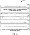
- FIG. 5is a flowchart of a process for controlling the temperature of a building space using the thermostat of FIG. 2A , according to an example embodiment.
- FIG. 6is a flowchart of a process for measuring the baseline of an occupancy indicator, according to an example embodiment.
- FIG. 7is a flowchart of a process for adjusting environmental setpoints of an HVAC system, according to an example embodiment.
- thermostatincluding occupancy detection logic is shown, according to various example embodiments.
- the thermostat described hereinmay be used in any HVAC system, room, environment, or system within which it is desired to control and/or observe environmental conditions (e.g., temperature, humidity, etc.).
- thermostatsmay include a passive infrared system to determine whether any occupants are present.
- the traditional systemmay provide a false indication of zero occupancy.
- sensorsmay only indicate if any occupants are present; they do not provide any indications as to how many occupants are in a building space. Such information may be crucial for proper operation of an HVAC system. Occupants emit heat. As such, when a number of occupants suddenly enter into a building space, the temperature in the building space begins to rise.
- Any response by the HVAC systemmay be delayed, as it will take time for a temperature sensor associated with the thermostat to sense the temperature increase. Further, due to the continuous emission of heat by the occupants, the amount of warm or cool air that the HVAC system must supply to the building space to maintain temperature at a setpoint changes. Thus, traditional thermostats fail to operate optimally during times of heightened occupancy.
- the thermostat disclosed hereincan be configured to solve such shortcomings by utilizing a proxy to determine the level of occupancy in a building space.
- the thermostat disclosed hereinmay detect the concentration level of a human-generated gas (e.g., carbon dioxide) using a gas sensor.
- a human-generated gase.g., carbon dioxide
- Fresh airhas about 0.04% concentration by volume of carbon dioxide and around a 20.9% concentration by volume of oxygen.
- the air that a human exhales, in contrastis about 4-5.5% concentration by volume of carbon dioxide and about 13.5-16% concentration by volume of oxygen.
- the concentration percentage of carbon dioxidewill trend towards the latter concentration.
- the concentration of carbon dioxide in the building spaceis proportional to the occupancy of the building space.
- the thermostat disclosed hereincan be configured to determine a number of baseline carbon dioxide concentration levels, readings generated by the gas sensor are then compared to the baselines to determine an occupancy level in the building space. In response to a heightened level of occupancy being detected, the thermostat disclosed herein can be configured to adjust the setpoints used to control the HVAC system.
- a heightened level of occupancymay be an increased level of occupancy, e.g., a increase in occupancy by a predefined amount. For example, a particular number of occupants increasing by a predefined amount, an occupancy percentage increasing by a predefined amount, etc.
- a thermostatmeasures a temperature of a building via a temperature sensor.
- the rate of change of the measured temperature of the buildingmay be lower than an actual change in temperature of the building for changes in occupancy.
- the temperature of the buildingmight increase significantly, creating an uncomfortable environmental condition, before the thermostat would determine to decrease the temperature of the building based on the measured temperature.
- proxy indicatorsthat are proportional and/or related to occupancy (e.g., audio signals of a microphone, occupant generated gas concentration levels of a gas sensor, camera signals of a camera, etc.) may change at a rate faster than the measured temperature in response to changes in occupancy.
- the thermostatcan preemptively control heating, cooling, and/or ventilation before the measured temperature changes or changes by a significant amount (e.g., an amount that causes a call for heating and/or cooling based on a setpoint).
- the preemptive controlcan be implemented by the thermostat by lowering a temperature setpoint and controlling building equipment with the lowered temperature setpoint and the sensed temperature.
- FIGS. 1-3illustrate an example environment, a building 10 , in which the current invention may be used.
- a HVAC system for building environmental managementis shown, according to an example embodiment.
- the HVAC systemmay be a communicating system employing one or more control devices (e.g., thermostats) functioning as system controllers.
- a building space 402is cooled by a system that includes a chiller 12 and a boiler 14 .
- chiller 12is disposed on the roof of building space 402 and boiler 14 is located in the basement; however, the chiller and boiler may be located in other equipment spaces or areas next to the building.
- Chiller 12is an air cooled or water cooled device that implements a refrigeration cycle to cool water.
- Chiller 12may be a stand-alone unit or may be part of a single package unit containing other equipment, such as a blower and/or integrated air handler.
- Boiler 14is a closed vessel that includes a furnace to heat water. The water from chiller 12 and boiler 14 is circulated through building space 402 by water conduits 16 . Water conduits 16 are routed to air handlers 18 , located on individual floors and within sections of building space 402 .
- Air handlers 18are coupled to ductwork 20 that is adapted to distribute air between the air handlers and may receive air from an outside intake (not shown).
- Air handlers 18include heat exchangers that circulate cold water from chiller 12 and hot water from boiler 14 to provide heated or cooled air.
- Fans, within air handlers 18draw air through the heat exchangers and direct the conditioned air to environments within building space 402 , such as spaces, apartments, or offices, to maintain the environments at a designated temperature.
- a thermostat 22shown here as including a thermostat, may be used to designate the temperature of the conditioned air.
- Thermostat 22also may be used to control the flow of air through and from air handlers 18 and to diagnose mechanical or electrical problems with the air handlers 18 .
- control devicemay, of course, be included in the system, such as control valves that regulate the flow of water and pressure and/or temperature transducers or switches that sense the temperatures and pressures of the water, the air, and so forth.
- control devicemay communicate with computer systems that are integrated with or separate from other building control or monitoring systems, and even systems that are remote from the building.
- FIG. 2Ais a drawing of the thermostat 22 of FIG. 1 shown to include a transparent cantilevered user interface 23 , according to an exemplary embodiment.
- the user interface 23may be an interactive display that can display information to a user and receive input from the user.
- the user interface 23may be transparent such that a user can view information on the display and view the surface (e.g., a wall) located behind the display.
- Thermostats with transparent and cantilevered user interfacesare described in further detail in U.S. patent application Ser. No. 15/146,649 filed May 4, 2016, the entirety of which is incorporated by reference herein.
- the user interface 23can be a touchscreen or other type of electronic display configured to present information to a user in a visual format (e.g., as text, graphics, etc.) and receive input from a user (e.g., via a touch-sensitive panel).
- the user interface 23may include a touch-sensitive panel layered on top of an electronic visual display.
- a usercan provide inputs through simple or multi-touch gestures by touching the user interface 23 with one or more fingers and/or with a stylus or pen.
- the user interface 23can use any of a variety of touch-sensing technologies to receive user inputs, such as capacitive sensing (e.g., surface capacitance, projected capacitance, mutual capacitance, self-capacitance, etc.), resistive sensing, surface acoustic wave, infrared grid, infrared acrylic projection, optical imaging, dispersive signal technology, acoustic pulse recognition, or other touch-sensitive technologies known in the art. Many of these technologies allow for multi-touch responsiveness of user interface 23 allowing registration of touch in two or even more locations at once.
- capacitive sensinge.g., surface capacitance, projected capacitance, mutual capacitance, self-capacitance, etc.
- resistive sensinge.g., surface acoustic wave, infrared grid, infrared acrylic projection, optical imaging, dispersive signal technology, acoustic pulse recognition, or other touch-sensitive technologies known in the art.
- Many of these technologiesallow for multi-
- the displaymay use any of a variety of display technologies such as light emitting diode (LED), organic light-emitting diode (OLED), liquid-crystal display (LCD), organic light-emitting transistor (OLET), surface-conduction electron-emitter display (SED), field emission display (FED), digital light processing (DLP), liquid crystal on silicon (LCoC), or any other display technologies known in the art.
- the user interface 202is configured to present visual media (e.g., text, graphics, etc.) without requiring a backlight.
- FIG. 2Billustrates a residential heating and cooling system.
- the residential heating and cooling systemmay provide heated and cooled air to a residential structure, as well as provide outside air for ventilation and provide improved indoor air quality (IAQ) through devices such as ultraviolet lights and air filters.
- a residence 24will include refrigerant conduits 26 that operatively couple an indoor unit 28 to an outdoor unit 30 .
- Indoor unit 28may be positioned in a utility space, an attic, a basement, and so forth.
- Outdoor unit 30is typically situated adjacent to a side of residence 24 and is covered by a shroud to protect the system components and to prevent leaves and other contaminants from entering the unit.
- Refrigerant conduits 26transfer refrigerant between indoor unit 28 and outdoor unit 30 , typically transferring primarily liquid refrigerant in one direction and primarily vaporized refrigerant in an opposite direction.
- a coil in outdoor unit 30serves as a condenser for recondensing vaporized refrigerant flowing from indoor unit 28 to outdoor unit 30 via one of the refrigerant conduits 26 .
- a coil of the indoor unitdesignated by the reference numeral 32 , serves as an evaporator coil.
- Evaporator coil 32receives liquid refrigerant (which may be expanded by an expansion device, not shown) and evaporates the refrigerant before returning it to outdoor unit 30 .
- Outdoor unit 30draws in environmental air through its sides as indicated by the arrows directed to the sides of the unit, forces the air through the outer unit coil using a fan (not shown), and expels the air as indicated by the arrows above the outdoor unit.
- a fannot shown
- the airis heated by the condenser coil within the outdoor unit and exits the top of the unit at a temperature higher than it entered the sides.
- Airis blown over indoor coil 32 and is then circulated through residence 24 by means of ductwork 20 , as indicated by the arrows entering and exiting ductwork 20 .
- the overall systemoperates to maintain a desired temperature as set by thermostat 22 .
- the air conditionerWhen the temperature sensed inside the residence is higher than the set point on the thermostat (with the addition of a relatively small tolerance), the air conditioner will become operative to refrigerate additional air for circulation through the residence. When the temperature reaches the setpoint (with the removal of a relatively small tolerance), the unit will stop the refrigeration cycle temporarily.
- the coil of outdoor unit 30will serve as an evaporator to evaporate refrigerant and thereby cool air entering outdoor unit 30 as the air passes over the outdoor unit coil.
- Indoor coil 32will receive a stream of air blown over it and will heat the air by condensing a refrigerant.
- FIG. 3is a block diagram of an HVAC system 42 that includes the thermostat 22 , indoor unit 28 functioning as an air handler, and outdoor unit 30 functioning as a heat pump.
- Refrigerantflows through system 42 within a closed refrigeration loop 44 between outdoor unit 30 and indoor unit 28 .
- the refrigerantmay be any fluid that absorbs and extracts heat.
- the refrigerantmay be hydro fluorocarbon (HFC) based R-410A, R-407C, or R-134a.
- HFChydro fluorocarbon
- control circuits 48 and 46The operation of indoor and outdoor units 28 and 30 is controlled by control circuits 48 and 46 , respectively.
- the control circuits 46 and 48may execute hardware or software control algorithms to regulate the HVAC system.
- the control circuitsmay include one or more microprocessors, analog to digital converters, non-volatile memories, and interface boards.
- the control circuitsmay be fitted with or coupled to auxiliary control boards that allow conventional 24 VAC wiring to be controlled through serial communications.
- the control circuits 46 and 48may receive control signals from thermostat 22 and transmit the signals to equipment located within indoor unit 28 and outdoor unit 30 .
- outdoor control circuit 46may route control signals to a motor 50 that powers a fan 52 and to a motor 54 that powers a compressor 56 .
- Indoor control circuit 48may route control signals to a motor 58 that powers a fan 60 .
- the control circuitsalso may transmit control signals to other types of equipment such as valves 62 and 64 , sensors, and switches.
- thermostat 22may communicate with control circuits 46 and 48 by transmitting communication packets over a serial communication interface.
- Thermostat 22may function as the master system controller while control circuits 46 and 48 operate as slave devices.
- thermostat 22may send a ping message to discover connected slave devices and their properties.
- control circuits 46 and 48may transmit an acknowledgement message in response to receiving a ping message from thermostat 22 .
- Control circuits 46 and 48also may transmit information, in response to requests from thermostat 22 , identifying the type of unit and specific properties of the unit.
- control circuit 46may transmit a signal to thermostat 22 indicating that it controls a two-stage heat pump with auxiliary heat and a bonnet sensor.
- Control circuits 46 and 48also may transmit signals identifying terminal connections and jumper settings of the control circuits.
- Thermostat 22may operate to control the overall heating and cooling provided by indoor and outdoor units 28 and 30 .
- Indoor and outdoor units 28 and 30include coils 66 and 32 , respectively, that both operate as heat exchangers.
- the coilsmay function either as an evaporator or a condenser depending on the heat pump operation mode.
- outside coil 32when heat pump system 42 is operating in cooling (or “AC”) mode, outside coil 32 functions as a condenser, releasing heat to the outside air, while inside coil 66 functions as an evaporator, absorbing heat from the inside air.
- outside coil 32When heat pump system 42 is operating in heating mode, outside coil 32 functions as an evaporator, absorbing heat from the outside air, while inside coil 66 functions as a condenser, releasing heat to the inside air.
- a reversing valvemay be positioned on closed loop 44 to control the direction of refrigerant flow and thereby to switch the heat pump between heating mode and cooling mode.
- Heat pump system 42also includes two metering devices 62 and 64 for decreasing the pressure and temperature of the refrigerant before it enters the evaporator.
- the metering devicesalso regulate the refrigerant flow entering the evaporator so that the amount of refrigerant entering the evaporator equals, or approximately equals, the amount of refrigerant exiting the evaporator.
- the metering device useddepends on the heat pump operation mode. For example, when heat pump system 74 is operating in cooling mode, refrigerant bypasses metering device 62 and flows through metering device 64 before entering inside coil 66 , which acts as an evaporator.
- refrigerantwhen heat pump system 42 is operating in heating mode, refrigerant bypasses metering device 64 and flows through metering device 62 before entering outside coil 32 , which acts as an evaporator.
- a single metering devicemay be used for both heating mode and cooling mode.
- the metering devicestypically are thermal or electronic expansion valves, but also may be orifices or capillary tubes.
- the refrigerantenters the evaporator, which is outside coil 32 in heating mode and inside coil 66 in cooling mode, as a low temperature and pressure liquid. Some vapor refrigerant also may be present as a result of the expansion process that occurs in metering device 62 or 64 .
- the refrigerantflows through tubes in the evaporator and absorbs heat from the air changing the refrigerant into a vapor.
- the indoor air flowing across the multichannel tubesalso may be dehumidified. The moisture from the air may condense on the outer surface of the multichannel tubes and consequently be removed from the air.
- compressor 56After exiting the evaporator, the refrigerant flows into compressor 56 .
- Compressor 56decreases the volume of the refrigerant vapor, thereby, increasing the temperature and pressure of the vapor.
- the compressormay be any suitable compressor such as a screw compressor, reciprocating compressor, rotary compressor, swing link compressor, scroll compressor, or turbine compressor.
- the increased temperature and pressure vapor refrigerantflows into a condenser, the location of which is determined by the heat pump mode.
- cooling modethe refrigerant flows into outside coil 32 (acting as a condenser).
- Fan 52which is powered by motor 50 , draws air across the tubes containing refrigerant vapor.
- the fanmay be replaced by a pump that draws fluid across the multichannel tubes. The heat from the refrigerant is transferred to the outside air causing the refrigerant to condense into a liquid.
- the refrigerantflows into inside coil 66 (acting as a condenser).
- Fan 60which is powered by motor 58 , draws air across the tubes containing refrigerant vapor. The heat from the refrigerant is transferred to the inside air causing the refrigerant to condense into a liquid.
- the refrigerantflows through the metering device ( 62 in heating mode and 64 in cooling mode) and returns to the evaporator (outside coil 32 in heating mode and inside coil 66 in cooling mode) where the process begins again.
- motor 54drives compressor 56 and circulates refrigerant through reversible refrigeration/heating loop 44 .
- the motormay receive power either directly from an AC or DC power source or from a variable speed drive (VSD).
- the motormay be a switched reluctance (SR) motor, an induction motor, an electronically commutated permanent magnet motor (ECM), or any other suitable motor type.
- SRswitched reluctance
- ECMelectronically commutated permanent magnet motor
- Control circuit 46may receive control signals from thermostat 22 .
- thermostat 22may receive information from sensors 68 .
- One sensor 68may measure the ambient indoor air temperature. Thermostat 22 then compares the air temperature to the temperature set point (which may be input by a user) and engages compressor motor 54 and fan motors 50 and 58 to run the cooling system if the air temperature is above the temperature set point.
- thermostat 22compares the air temperature from sensor 68 to the temperature set point and engages motors 50 , 54 , and 58 to run the heating system if the air temperature is below the temperature set point.
- Thermostat 22may also receive information from another sensor 68 that measures various indicators of occupancy inside of a building.
- the sensor 68comprises a gas sensor capable of measuring the concentration level of a human-generated gas.
- the control devicecompares the concentration level to a baseline established by the methods disclosed herein to determine if the building has a heightened level of occupancy. If the concentration level indicates that there is a heightened level of occupancy in the building, the thermostat 22 may adjust the temperature setpoints against which the measurements from the temperature sensor 68 are compared to control the HVAC system 42 . In an example embodiment, the thermostat 22 is configured to lower the setpoints by an adjustment amount.
- the adjustment amountsmay depend on a variety of factors such as the setpoint prior to the heightened level of occupancy detected, an occupancy level estimation based on the measured concentration level, and weather conditions external to the building.
- the HVAC system 42maintained the temperature inside the building at or near the previous setpoint
- the lowering of the setpointswill cause the HVAC system 42 to begin cooling the building immediately in response to the heightened level of occupancy being detected.
- the thermostat 22pre-emptively cools the building to counteract the effects of a heightened level of occupancy.
- control devicemay compare the air temperature as measured by the sensing device 68 to the setpoints to maintain the setpoints used to control the HVAC system 42 .
- the thermostat 22may also control the ventilation to the building.
- the thermostat 22may control various actuators associated with various dampers in the outdoor unit 30 to control the rates at which inside air is expelled to the exterior of the building or outside air is directed to the interior of the building.
- the thermostat 22may control the ventilator or amount of air introduced into various zones (e.g., rooms) of the building by controlling various dampers associated with an air supply duct.
- the control circuit 46 and thermostat 22also may initiate a defrost cycle when the system is operating in heating mode.
- the outdoor temperatureapproaches freezing, moisture in the outside air that is directed over outside coil 32 may condense and freeze on the coil.
- Sensorsmay be included within outdoor unit 30 to measure the outside air temperature and the temperature of outside coil 32 . These sensors provide the temperature information to the control circuit 46 which determines when to initiate a defrost cycle.
- System 400is shown to include a thermostat 22 installed within a building space 402 .
- the building space 402includes a single thermostat 22 .
- Thermostat 22is shown to include a user interface 406 , a temperature sensor 408 , and an occupancy sensor 410 .
- User interface 406includes an electronic display for presenting information to a user 414 and one or more physical input devices (e.g., a rotary knob, pushbuttons, manually-operable switches, etc.) for receiving input from a user 414 .
- Temperature sensor 408measures the temperature of building space 402 and provides the measured temperature to user interface 406 .
- the occupancy sensors 410are configured to measure various indicators of the occupancy level (e.g., the number of occupants 412 ) within the building space 402 .
- One such sensormay include a gas sensor.
- the gas sensormay include a nondispersive infrared (NDIR) carbon dioxide sensor including an air intake, air outtake, with a volume between the air intake and the air outtake.
- a radiation sourcemay radiate at a predetermined intensity through the volume. The amount of radiation absorbed by the air in the volume may be proportional to the concentration of carbon dioxide in the air.
- the gas sensormay determine a concentration (e.g., in parts-per-million or “PPM”) of carbon dioxide in the air.
- concentration measurementsmay be used to both establish a baseline concentration level and to determine an occupancy level of the building space 402 .
- a more detailed explanation of the occupancy sensors 410will be provided below in relation to FIG. 4B .
- the thermostat 22communicates with a controller 416 .
- the controller 416may be integrated with thermostat 22 or may exist as a separate controller (e.g., a field and equipment controller, a supervisory controller, etc.) that receives input from the thermostat 22 .
- the thermostat 22may send temperature measurements and temperature setpoints to the controller 416 .
- the controller 416generates control signals for HVAC equipment 418 .
- the HVAC equipment 418includes the HVAC system 42 discussed above in relation to FIG. 3 .
- the control signalsmay cause control circuits 46 or 48 to control the operation of motors 50 , 54 , and 58 so as to change the amount of heating or cooling provided to the building space 402 .
- Thermostat 22is shown to include a variety of user interface devices 406 and sensors 420 .
- User interface devices 406may be configured to receive input from the user 414 and provide outputs to the user 414 in various forms.
- user interface devices 406are shown to include a touch-sensitive panel 422 , electronic display 424 , ambient lighting 426 , and speakers 428 .
- user interface devices 406include a microphone configured to receive voice commands from a user, a keyboard or buttons, switches, dials, or any other user-operable input devices.
- user interface devices 406may include any type of device configured to receive input from a user and/or provide an output to a user in any of a variety of forms (e.g., touch, text, video, graphics, audio, vibration, etc.).
- Sensors 420may be configured to measure a variable state or condition of the environment in which the thermostat 22 is installed (e.g., the building space 402 ). Sensors 420 may be integrated into the thermostat 22 or be remote from the thermostat 22 and communicate with the thermostat 22 (e.g., wirelessly via the data communications interface 462 ).
- the thermostat 22includes the temperature sensor 408 and a humidity sensor 430 for measuring qualities of the air in the building space 402 .
- the thermostat 22may include various other sensors for measuring additional qualities of the air in the building space 402 .
- the thermostat 22may also include an air quality sensor configured to detect the presence of various impurities in the air (e.g., nitrogen dioxide, carbon monoxide, etc.).
- the thermostat 22includes a plurality of occupancy sensors 410 .
- the occupancy sensorsare configured to generate signals that are based at least in part on an indication of an occupant being in the building space 402 .
- occupancy sensors 410may include a gas sensor 432 that measures the concentration level of at least one human-generated gas in the air of the building space 402 .
- the thermostat 22includes a plurality of gas sensors 432 .
- the thermostatmay further include an oxygen sensor (e.g., an optical oxygen electrical sensor).
- the thermostat 22may receive indicators of a carbon dioxide concentration level and an oxygen concentration level in the air. Using such indicators, baselines for both oxygen concentration levels as well as carbon dioxide concentration levels may be established for the building space 402 via the methods described herein.
- the gases detected by the gas sensors 432can include volatile organic compounds (VOCs) (e.g., methanol, isoprene, acetone, ethanol, and/or other alcohols), carbon dioxide (CO2), nitrogen dioxide (NO2), oxygen (O), etc.
- VOCsvolatile organic compounds
- CO2carbon dioxide
- NO2nitrogen dioxide
- Ooxygen
- Occupancy sensors 410further include a camera 434 .
- Camera 434may capture digital still images and/or videos of the building space 402 .
- the thermostat 22may further include various image processing modules (e.g., the image processing module 456 described below) configured to analyze the image captured by the camera to determine if an occupant is present in the building space 402 .
- Occupancy sensors 420may further include a light sensor 436 (e.g., a photodiode) configured to generate a signal when certain wavelengths of light that are indicative of occupancy (e.g., lights emitted from displays of a user computing device) are detected, a proximity sensor 438 , a microphone 440 , and a vibration sensor 442 .
- the camera 434is an infrared (IR) camera that captures a signal with each pixel representing an amount of thermostat energy associated with each pixel.
- IRinfrared
- thermostat 22is shown to include a communications interface 462 and a processing circuit 444 .
- Communications interface 462may include wired or wireless interfaces (e.g., jacks, antennas, transmitters, receivers, transceivers, wire terminals, etc.) for conducting data communications with various systems, devices, or networks.
- communications interface 462may include an Ethernet card and port for sending and receiving data via an Ethernet-based communications network and/or a Wi-Fi transceiver for communicating via a wireless communications network.
- Communications interface 462may be configured to communicate via local area networks or wide area networks (e.g., the Internet, a building WAN, etc.) and may use a variety of communications protocols (e.g., BACnet, IP, LON, etc.). Communications interface 462 may include a network interface configured to facilitate electronic data communications between the thermostat 22 and various external systems or devices (e.g., the controller 416 and/or HVAC equipment 418 ).
- local area networks or wide area networkse.g., the Internet, a building WAN, etc.
- Communications interface 462may include a network interface configured to facilitate electronic data communications between the thermostat 22 and various external systems or devices (e.g., the controller 416 and/or HVAC equipment 418 ).
- Processing circuit 444is shown to include a processor 446 and memory 448 .
- Processor 446may be a general purpose or specific purpose processor, an application specific integrated circuit (ASIC), one or more field programmable gate arrays (FPGAs), a group of processing components, or other suitable processing components.
- ASICapplication specific integrated circuit
- FPGAsfield programmable gate arrays
- Processor 446may be configured to execute computer code or instructions stored in memory 448 or received from other computer readable media (e.g., CDROM, network storage, a remote server, etc.).
- Memory 448may include one or more devices (e.g., memory units, memory devices, storage devices, etc.) for storing data and/or computer code for completing and/or facilitating the various processes described in the present disclosure.
- Memory 448may include random access memory (RAM), read-only memory (ROM), hard drive storage, temporary storage, non-volatile memory, flash memory, optical memory, or any other suitable memory for storing software objects and/or computer instructions.
- Memory 448may include database components, object code components, script components, or any other type of information structure for supporting the various activities and information structures described in the present disclosure.
- Memory 448may be communicably connected to processor 448 via processing circuit 444 and may include computer code for executing (e.g., by processor 446 ) one or more processes described herein.
- memory 748is shown to include an occupant tracker module 450 and an occupancy level module 452 .
- the occupant tracker module 450is structured to cause the processor 446 to determine the location of various occupants of the building space 402 .
- the occupant tracker module 450is configured to process signals produced by the occupancy sensors 410 to track the location of various occupants. For example, in response to the proximity sensor 438 detecting the presence of an occupant, the occupant tracker module 450 may identify the location of the occupant as being within a predetermined distance of the thermostat 22 . Alternatively or additionally, the occupant tracker module 450 may also identify the location of various occupants using the camera 434 and/or microphone 440 .
- the occupant tracker module 450may identify the location of various color contrasts in images captured by the camera 434 (e.g., to identify the location of a flesh color) to determine that an occupant is present. Additionally, the occupant tracker module 450 may further analyze the image data to determine the relative distance of the occupant from the thermostat 22 . For example, such a determination may be made based on the size of a particular attribute of the identified occupant (e.g., the face). The occupant tracker module 450 may perform a similar analysis on sound data received from microphones 440 . For example, an occupant may be identified based on the frequency composition of a sound received by the microphone 440 , and a relative distance of the occupant from the thermostat 22 may be determined based on a sound pressure level measured by the microphone 440 .
- additional equipmentmay be used to track building occupants.
- the thermostat 22is connected to an external network associated with the building space.
- a plurality of additional devicese.g., mobile devices
- This external networkmay be generated through a plurality of routers associated with a building management system (not shown) associated with the building space.
- the routersmay provide access points to the network. Such routers may engage in bi-directional communications with the devices and thermostat 22 .
- the routersmay receive a connection request from a user device associated with the user 414 including login credentials, and transmit an encryption key or the like to the user device to establish a secure connection with the user device.
- the user devicemay communicate with a remote server of the building management system to receive webpages from the building management containing various forms of information pertaining to various aspects of the building (e.g., the HVAC system 42 , sensor values measured by sensors 420 , etc.). Similar procedures may be followed for other devices associated with occupants 412 .
- the routersmay measure the strength of the wireless signals received from the user devices.
- the signal strengthsmay be communicated by the routers to the thermostat 22 which, by the occupant tracker module 450 , may determine the location of a specific device (and therefor an associated occupant 412 ) based on the strength of the signals and location information pertaining to the routers stored on the thermostat 22 . Accordingly, the precise location for each occupant 412 in the building having such a device may be measured.
- the building space 402may include a plurality of sets of sensors 420 to precisely measure the location of various building occupants.
- a floorplan 464 of a building spaceis shown, according to an example embodiment.
- the building spaceis shown to include several different zones (e.g., rooms or areas) including a living room, a first bedroom, a second bedroom, a bathroom, a kitchen, and a dining room.
- a sensor unit 466 including the set of sensors 420 discussed abovemay be installed in each one of the rooms or zones.
- One zonemay include a main control unit.
- FIG. 4Cshows a main control unit (e.g., thermostat 22 ) installed in the living room.
- the main control unitmay serve as a central hub for monitoring environmental conditions, controlling various devices throughout the home, and/or tracking occupancy through multiple rooms and/or zones of the home.
- Sensor units 466 including any combination of the sensors 420 discussed abovemay be installed in various rooms or zones in the home.
- FIG. 4Cshows a sensor unit installed in each of the bedrooms, the bathroom, the kitchen, and the dining room.
- the sensor units 466measure signals strengths between user devices similar to the routers discussed above.
- sensor units 466are configured to relay image data, audio data, gas concentration data, or other data to thermostat 22 (e.g., by the external network discussed above).
- Thermostat 22may locate the occupants and identify occupancy levels of various zones of the building based on the received signals.
- each sensor unit 466may have an associated identifier stored at the thermostat 22 .
- the thermostat 22may determine a precise location for various occupants within the building. Using such locations, the thermostat 22 may control the heating and/or cooling provided to each of the zones.
- each room or zonemay include a separate air handling unit (e.g., as discussed above with respect to FIG. 1 ), and thermostat may provide control signals to control the amount of warm or cool air provided to each one of the zones via the methods disclosed herein.
- the memory 448is shown to further include an occupancy level module 452 .
- the occupancy level module 452is structured to cause the processor 446 to analyze various forms of data received by the thermostat 22 to determine an occupational level of a building or zone thereof.
- the occupancy level module 452includes a concentration level tracking module 454 , an image processing module 456 , an audio processing module 458 , and a setpoint determination module 460 .
- the modules 454 - 460are illustrated as being separate from one another, the memory 448 may include a different number of modules performing the same functions as the modules 454 - 460 . For example, a single module may perform each of the functions discussed below with respect to the modules 454 - 460 .
- the baseline determination module 454is configured to determine a baseline concentration level for various gases detected by the gas sensors 432 .
- the baseline determination module 454may keep a global average of carbon dioxide concentration levels in the building space 402 .
- the global averagemay include a weighted average of all the concentration level values measured by the gas sensors 432 . Values closer to an established baseline of the building space 402 , for example, may receive greater weight than values further from the established baseline.
- the baseline determination module 454may continuously update the global average value (e.g., daily, weekly, monthly, etc.).
- baseline determination module 454is configured to determine circumstantial concentration baselines.
- Circumstantial baselinesmay include baselines for various levels of occupancy in the building space 402 .
- One such circumstantial concentration baselinemay include a no-occupancy carbon dioxide concentration level baseline.
- the baseline determination module 454is configured to identify various time periods in which there are no occupants in the building space 402 , and keep an average of the carbon dioxide concentration levels measured by the gas sensor 432 during those times.
- the baseline determination module 454is configured to identify periods of no occupancy based solely on carbon dioxide concentration levels. When at least one occupant is within the building space 402 for a prolonged period, the carbon dioxide concentration within the air of the building space will generally be slightly higher than when there are no occupants in the building space for a prolonged period.
- the baseline determination module 454is configured to monitor the concentration values returned by the gas sensor 432 for steady state local minimums. For example, if successive readings over the course of a predetermined period are within a predetermined range of one another and average to a value that is lower than a previously-determined steady state average, the baseline determination module 454 may identify that steady state average as no-occupancy value. A plurality of such values may be averaged together to establish the no-occupancy carbon dioxide concentration level baseline. As with the global averages discussed above, the baseline determination module 454 may continuously update the baseline value.
- the baseline determination module 454may receive occupancy estimates from the image and audio processing modules 454 and 456 at various times.
- the baseline determination module 454may store concentration levels returned by the gas sensor 432 in association with the estimates provided based on the camera 434 and 434 and establish baselines via the methods described above.
- the baseline determination module 454compares the concentrations levels measured by the gas sensor 432 to these baselines to estimate the level of occupancy in the building space 402 .
- the baseline determination module 454is also configured to identify local trends in the data captured by the gas sensor(s) 432 . Such local trends may also reveal a heightened level of occupancy in the building space 402 . For example, the rate of change of the concentration of carbon dioxide (or in any zone thereof) being above a predetermined rate threshold may be indicative of a heightened level of occupancy even if the concentration remains relatively close to the established baseline. It should be understood that in embodiments where the thermostat 22 receives data from multiple gas sensors 432 (e.g., carbon dioxide sensors being placed in different rooms), the baseline determination module 454 may perform a similar set of operations with respect to each sensor.
- the image processing module 456is configured process images captured by the camera 434 associated with the user thermostat 22 to further discern the level of occupancy in the building space 402 .
- the image processing module 456includes image processing algorithms configured to identify various features in the images captured by the camera 434 or other cameras.
- one image processing algorithmmay search the images captured by the camera 434 for occupant signatures.
- An occupant signaturemay include any attribute that is typically associated with an occupant such as, but not limited to, a face, pair of arms, a movement pattern, a piece of clothing, or any combination thereof.
- the image processing algorithmmay scan an image captured by the camera 434 for flesh-colored groups of pixels. Based on various groupings of flesh-colored pixels, the image processing algorithm may generate an occupancy level estimate (e.g., based on the number of heads or faces that were located). In another example, the image processing module 456 may assess a series of images captured by the camera 434 to estimate the occupancy level of the building space 402 . For example, motion detection software may identify objects that move from frame to frame in the successive images. The algorithm may estimate the occupancy level based on the number of detected objects meeting human-identifying parameters (e.g., defining the sizes of various human attributes) that moved.
- human-identifying parameterse.g., defining the sizes of various human attributes
- the audio processing module 458is configured to process audio signals captured by the microphone 440 or any other microphones located throughout the building space 402 to further discern the level of occupancy in the building space 402 .
- the audio processing module 458may include a series of predetermined audio signatures thereon.
- the audio signaturesmay be associated with a plurality of regular occupants of the building space 402 .
- the audio processing module 458may include a data logger that stores various segments of captured audio signals. Each segment may be associated with a different regular occupant based on various aspects of the sound described by the signal (e.g., frequency band composition, pressure levels, texture, etc.).
- the segmentsmay be stored at the user thermostat 22 or in a remote server of the building management 610 .
- Such segmentsmay be captured during an initiation process of the thermostat 22 .
- the audio processing module 458may determine that a particular occupant is “regular” if similar audio signals are captured on successive days, for example.
- various comparisonsmay be run to determine if the speech was emitted by a regular occupant. If an irregular signature is detected, this may be a sign that the owner of the building space 402 is having company over, and therefore a sign of heightened occupancy.
- the audio processing module 458may identify period of heightened occupancy based on the combination of sound signals being received by the microphone 440 . In a crowded room, many occupants having different voices may emit sounds at once. Thus, by decomposing the received signal from the microphone 440 into the frequency various frequency bins (e.g., via the Fast Fourier Transform algorithm) and applying various filtering modules (e.g., noise gates) the audio processing module 458 may estimate the number of occupants based on various frequency band groupings in the received signal.
- various filtering modulese.g., noise gates
- the occupancy level module 452may use multiple modes for estimating the occupancy to verify occupancy level estimates. For example, the occupancy level module 452 may obtain a first estimate for the occupancy level based on the carbon dioxide concentration, a second estimate based on images captured by the camera 434 , and a third based on sound signals captured by the microphone 440 . In one embodiment, the occupancy level module 452 uses the estimate given by the baseline determination module 454 as a primary estimate for occupancy level, and uses the image processing module 456 and/or the audio processing module 458 to verify the estimation given by the baseline determination module 454 .
- the occupancy level module 452uses that as an estimate for the current state of occupancy for the building space 402 . In some embodiments, the occupancy level module 452 only provides an estimate of the occupancy of building space 402 if each of the estimates given by the baseline determination module 454 , image processing module 456 , and audio processing module 458 fall within a predetermined range of one another.
- Setpoint determination module 460is configured to adjust environmental setpoints based on the occupation level estimates provided by the baseline determination module 454 , image processing module 456 , and audio processing module 458 .
- a usermay provide environmental setpoint inputs to the thermostat 22 via the user interface 406 .
- Environmental setpoint inputsmay indicate user preferences as to the temperature, humidity, and concentration levels (e.g., carbon dioxide concentration levels) of the building space 402 .
- concentration levelse.g., carbon dioxide concentration levels
- the environmental conditions of the building space 402are monitored via 420 which provide control signals to the HVAC equipment 418 (e.g., the controller 416 ) to maintain the air conditions in the building space 402 at the setpoints.
- the controller 416may control the motors 50 , 54 , and 58 to increase the amount of cool air provided to the building space 402 .
- the environmental conditions in the building space 402quickly start to deviate from the user-input environmental setpoints. People continuously give off heat.
- the building space 402will begin rise above the setpoint once the additional occupants arrive.
- the temperature sensor 408will eventually detect such a deviation and provide control signals to the HVAC system 42 to counteract the increase, such a response is often delayed, as it takes time for the temperature of the building space 402 to appreciably rise.
- the heightened occupancyhave other undesired consequences on the air in the building space 402 . For example, a great number of occupants in a building may increase water vapor levels, making the building space 402 feel stuffy.
- the systems and methods disclosed hereinuse the occupancy level estimates generated by the methods discussed above to modify the setpoints from those that were set by the user.
- the camera 434may capture images of the building space 402
- the thermostat 22e.g., by the processor 446 executing the image processing module 456
- the HVAC system 42may anticipate the above-described undesired changes.
- the thermostat 22executes the setpoint determination module 460 once building occupancy is estimated so as to pre-emptively control the HVAC equipment 418 .
- the setpoint determination module 460receives user-input environmental setpoints and estimated occupancy level as inputs and computes adjustments to the setpoints based on the estimated occupancy level.
- the adjustmentsmay be computed based on a plurality of additional factors. For example, the adjustments may be further based on a baseline level of occupancy in the building space 402 . In such an embodiment, is presumed that the user-input setpoints were provided with the baseline level of occupancy in mind. Thus, adjustments may only be made if the current occupancy level of the building space 402 deviates from the baseline level of occupancy by more than a predetermined threshold.
- the setpoint determination module 460may compare the occupancy level estimated via the methods described above with a baseline occupancy level. Methods for computing such a baseline are described below with respect to FIG. 10 . If the estimated occupancy level deviates from the baseline by more than a predetermined threshold, the setpoint determination module 460 computes a lowering-amount for the user-input setpoints. As a result, the HVAC equipment 418 will immediately provide lower temperature air to the building space 402 to counteract the above-mentioned unpleasant effects caused by the heightened occupancy.
- Setpoint determination module 460may include a number of lookup tables. Each lookup table may be associated with a user-input setpoint range. For example, one lookup table may be associated with a user-input temperature setpoint between 65 and 67 degrees Fahrenheit, another lookup table may be associated with a user-input temperature setpoint between 67 and 69 degrees Fahrenheit, and so on. Each lookup table may include a plurality of entries, with each entry including an estimated occupancy level and an adjustment amount.
- the setpoint determination module 460retrieves a user-input setpoint, and identifies an adjustment amount based on the user-input setpoint and the occupancy level estimate.
- the adjustment amountsmay be determined by the manufacturer of the thermostat 22 or be pre-calibrated upon installation of the thermostat 22 at the building space 402 .
- the adjustment amountsare based on the performance of the HVAC equipment 418 .
- HVAC equipment 418may have the capability of changing the temperature inside the building space 402 from a first temperature (i.e. setpoint) to a second temperature at a particular rate that depends on the temperatures involved.
- the setpoint adjustmentmay be chosen such that the HVAC equipment 418 counteracts the rate of temperature increase in the building space 402 caused by heightened levels of occupancy. Such rates may be determined based on the size of the building space 402 .
- various alterationsmay be made to the adjustment based on various other factors. For example, weather conditions received from a weather serve may be taken into account. To illustrate, the adjustment to the user-input setpoint may be enhanced (i.e., so as to further decrease the setpoint in response to a heightened occupancy) if an indication is received from the weather server that it is very warm (e.g., above 80 degrees Fahrenheit) outside the building space 402 . In another example, adjustments may be diminished if an indication is received that it is very windy outside the building.
- the setpoint determination module 460may transmit a heightened occupancy alert via the above described external network to a user device in response to an estimate of heightened occupancy.
- the alertmay enable the user to provide an input as to a user-preference for a setpoint adjustment. As such, the user may pre-emptively adjust the operation of the HVAC equipment 418 in accordance with the user's preferences.
- setpoint determination module 460may adjust various other operational aspects of HVAC equipment 418 . For example, in addition to adjusting the temperature of the air flowing into the building space 402 from a supply air duct, the setpoint determination module 460 may also compute adjustments to various ventilation rates of the HVAC equipment. For instance, setpoint determination module 460 may receive signals from various dampers disposed throughout the building space that indicate the position of the dampers, and the setpoint determination module 460 may compute adjustments to the dampers based on the occupancy estimates.
- the functionality of the thermostat 22is implemented in a smart ventilator.
- the smart ventilatormay include the gas sensor 432 and can be configured to operate itself in order to ventilate a building based on air quality. For example, if, via the gas sensor 432 , it is determined that the air quality is poor, the smart ventilator may operate to ventilate the building space 402 and improve the air quality of the building space 402 .
- a buildingmay include multiple smart ventilators, each configured to ventilate a particular area of a building. Since each of the smart ventilators may include a gas sensor 432 each smart ventilator can operate independently from each other. This causes only specific areas of the building to be ventilated as needed, realizing an energy usage reduction.
- Process 500may be performed by the system 400 , as described with reference to FIGS. 4A-4B .
- thermostat 22measures the temperature of the building space (step 502 ).
- User 414views the measured temperature and adjusts the temperature setpoint via user interface 406 of thermostat 22 (step 504 ).
- Thermostat 22sends the measured temperature and the setpoint to the controller 416 (step 506 ).
- Controller 416uses the measured temperature and the setpoint to generate and provide a control signal to HVAC equipment 418 to cause the temperature of the building space 402 to converge with the user-input setpoint (step 508 ).
- the thermostat 22monitors various indicators of occupancy in the building space (step 510 ).
- Occupancy sensors 410 of the thermostat 22may measure any aspect of the environment of the building space 402 that bears any sort of relationship to the occupancy level of the building space 402 .
- gas sensors 432may monitor a carbon dioxide concentration level in the building space 402
- a camera 434may take an image of the building space 402 .
- the thermostat 22estimates the level of occupancy in the building space and sends an in indication of the occupancy level to the controller 416 (step 512 ). For example, the thermostat 22 may compare a concentration level estimate generated based on a signal from the gas sensor 432 (e.g., via the baseline determination module 454 ) by comparing the sensor level to various baselines. If the concentration level is above a baseline, the thermostat may provide an indication of heightened occupancy to the controller 416 . Such an indication may include adjusted environmental setpoints (e.g., determined by the setpoint determination module 460 ).
- the controller 416In response to the heightened occupancy indication, the controller 416 provides control signals to the HVAC equipment 418 to cause the temperature of the building space 402 to converge with the adjusted setpoint (step 514 ). As such, the more cool air is supplied to the building so as to counteract the negative effects of heightened occupancy on air quality.
- FIG. 6a flowchart illustrating a baseline updating process 600 performed by the occupancy level module 452 of the thermostat 22 as described with reference to FIG. 4 is shown, according to an example embodiment.
- the thermostat 22continuously updates occupancy level benchmarks of the building space 402 such that pre-emptive adjustments to the HVAC equipment 418 only occurs when the level building occupancy significantly deviates from normal. As such, over-adjustment against user preferences is avoided.
- the thermostat 22is configured to monitor various occupancy indicators (step 602 ).
- the gas sensors 432may continuously provide signals indicative of the concentration levels of various gases in the air inside of the building space 402 .
- the microphone 440may continuously provide signals indicative of received sound signals meeting predetermined criteria (e.g., the microphone 440 may only provide signals to the occupancy level module 452 if sound signals captured largely resemble speech).
- the camera 434may periodically (e.g., every five minutes) capture an image of a zone of the building space 402 .
- the occupancy level module 452may transmit such data over a network to a remote server associated with the building for storage in association with the time when the data was captured.
- the baseline determination module 454may identify regular periods of heightened occupancy based on a pattern of heightened carbon dioxide concentration levels at particular times. If no patterns are detected from the received occupancy indicators, a previous occupancy baseline is maintained (step 606 ).
- the previous baselinemay be a previous average carbon dioxide concentration level, for example.
- the averageis a rolling weighted average over a predetermined period (e.g., weekly, bi-daily, etc.). For example, each measurement captured by the gas sensor 432 may receive a weight based on its statistical relationship to a common range of concentration levels. Concentration values within the predetermined range may receive greater weights than values outside of the range.
- the baseline determination module 454may include a plurality of such baselines, with each baseline corresponding to a different time interval. For example, a rolling average may be maintained for each hour over the course of a day.
- the detected patternis compared with a previously-established baseline value (step 608 ).
- the occupancy indicators received at 602may indicate a heightened level of occupancy during a specific time interval (e.g., Friday evenings).
- a baseline concentration value for that time intervalis retrieved and compared with the measured value. If the difference between the measured value and the established baseline for that time interval is not above a threshold, the previously-established baseline is maintained (step 606 ).
- the baselineis adjusted (step 610 ).
- the adjusted baselineis the average of the indicators received at step 602 (e.g., if a heightened carbon dioxide level is detected over the course of a specific time interval on successive weeks, the average of the detected levels may be established as the new baseline).
- baseline occupancy levelsare constantly updated by the thermostat 22 to avoid over-adjustment of environmental setpoints.
- an alertis transmitted to the user device or provided by way of the electronic display 424 of the thermostat 22 . The alert may indicate a pattern of heightened occupancy, and enable the user to establish a setpoint specifically for the time-interval of regular heightened occupancy.
- FIG. 7a flowchart 700 illustrating a process of controlling an HVAC system based on an occupancy proxy is shown, according to an example embodiment.
- the processmay be performed by the occupancy level module 452 of the thermostat 22 as described with reference to FIG. 4 .
- the thermostat 22may pre-emptively change the operation of an HVAC system in response to receiving an indication of heightened occupancy. As a result, comfortable air conditions are maintained.
- the thermostat 22is configured to monitor various occupancy indicators (step 702 ).
- the gas sensors 432may continuously provide signals indicative of the concentration levels of various gases in the air inside of the building space 402 .
- the microphone 440may continuously provide signals indicative of received sound signals meeting predetermined criteria (e.g., the microphone 440 may only provide signals to the audio processing module 458 if sound signals captured largely resemble speech).
- the camera 434may periodically (e.g., every five minutes) capture an image of a zone of the building space 402 .
- various operationsmay be performed on the received data to estimate a level of occupancy in the building space 402 .
- a concentration of carbon dioxide measured by a gas sensor 432may be converted to an occupancy level estimate using a lookup table in the baseline determination module 454 , or by comparing the level to various baselines.
- Images captured by the camera 434may be processed to search for occupant-specific features (e.g., movement patterns, edge shapes, etc.).
- a frequency analysismay be performed on any sound signals generated by the microphone 440 to estimate a number of occupants.
- the thermostat 22is configured to determine if the received indicators are above established baseline levels (step 704 ). For example, the thermostat 22 may perform the process 600 discussed above in relation to FIG. 6 to determine baseline levels for various occupancy level indicators at various times. Accordingly, via the occupancy level module 452 , the thermostat 22 may compare the indicators received at 702 to the established baselines. For example, if the gas sensor 432 measures a concentration level of carbon dioxide at a particular time, the thermostat 22 may retrieve a baseline carbon dioxide concentration level for that time, and compare the measured value to the retrieved value. In another example, various aspects of a sound signal generated by the microphone 440 (e.g., pressure levels, frequency compositions, etc.) may be compared to a baseline sound signal.
- a sound signal generated by the microphone 440e.g., pressure levels, frequency compositions, etc.
- the thermostat 22may compare occupation level estimates calculated based on the indicators to baseline occupation levels. For example, an image captured by the camera 434 may be processed by any of the methods disclosed herein to generate an estimate of the occupancy level. The estimate of the occupancy level may then be compared to a baseline occupancy level established by the method 600 discussed above.
- an indicatore.g., a gas concentration level or a sound signal
- the thermostat 22may compare occupation level estimates calculated based on the indicators to baseline occupation levels. For example, an image captured by the camera 434 may be processed by any of the methods disclosed herein to generate an estimate of the occupancy level. The estimate of the occupancy level may then be compared to a baseline occupancy level established by the method 600 discussed above.
- the thermostat 22is also configured to determine the rate at which occupancy in the building has increased. For example, the thermostat 22 may compare an occupancy level estimate based on the most recent indicators received at 702 to estimates based on a previous set of indicators (e.g., a set of indicators received a quarter hour previous). Thus, in such embodiments, the thermostat 22 responds to a rate of increase in the occupancy level rather than just the absolute level of occupancy in the building space 402 .
- the thermostat 22maintains the HVAC equipment 418 at its default heating and/or cooling setpoints (step 706 ). For example, via the user interface 702 discussed above, a user may establish default temperature setpoints for the building space 402 at various times. In the event that the occupation level in the building space 402 is at or below normal, these setpoints should be sufficient to maintain the inside of the building space 402 at a user-preferred temperature level.
- the baselinemay be a predefined rate and an occupancy signal and/or occupancy signals can be used to determine a rate and compared to the predefined rate.
- the thermostat 22can record multiple gas concentration levels and determine a rate at which the gas is changing. If the gas is changing at a rate greater than the predefined rate, this may indicate heightened occupancy, i.e., the occupancy has increased. Similarly, if an audio signal is increasing at a rate greater than the predefined rate, this may also indicate that the occupancy is heightened.
- the thermostat 22is configured to lower the heating and/or cooling setpoints from the user-default setpoints discussed above (step 710 ).
- a heightened level of occupancyresults in a temperature increase in the building space 402 and an increased load on the HVAC equipment 418 .
- the HVAC equipment 418will be sluggish to counteract any temperature increased caused by the heightened occupancy level.
- the temperature in the building space 402will generally be greater than the user prefers in times of occupancy.
- the thermostat 22(e.g., via the setpoint determination module 460 discussed above) transmit control signals to the controller 416 based on adjusted setpoints.
- the amount that the setpoints are adjustedmay depend on a plurality of factors such as the absolute number of occupants in the building estimated based on the indicators received at 702 , the level of the user-input setpoints, the weather outside of the building space 402 , and the particular zone within the building space 402 having the heightened occupancy (e.g., if the zone of heightened occupancy is a small room, the adjustment may be greater than if the zone is a large room).
- the lowering of the setpointscauses the thermostat 22 to pre-emptively counteract the negative impacts on air quality caused by heightened levels of occupancy. For example, when a period heightened level of occupancy inside the building space 402 first begins, the temperature in the building space 402 may be at or near a user-input default setpoint. Thus, lowering the setpoint causes the temperature sensor 408 to detect a difference between the setpoint temperature and the temperature inside the building space 402 . Such a difference causes the thermostat 22 to generate and transmit control signals to the HVAC equipment 418 that cause the HVAC equipment 418 to provide cooler air to the inside of the building space 402 .
- the thermostat 22may also be configured to determine if a ventilation response to a heightened level of occupancy is enabled (step 712 ).
- the thermostat 22may be utilized in conjunction with HVAC equipment 418 lacking ventilation capabilities, or the user may indicate a preference for reduced ventilation (e.g., so as to save energy).
- the control devicemaintains system ventilation at the current level (step 708 ).
- the thermostat 22requests additional ventilation from the HVAC equipment (step 714 ).
- the thermostat 22may transmit a control signal to actuators that control dampers in the outdoor unit 30 to cause the dampers to open.
- the building space 402is prevented from becoming stuffy.
- the present disclosurecontemplates methods, systems and program products on any machine-readable media for accomplishing various operations.
- the embodiments of the present disclosuremay be implemented using existing computer processors, or by a special purpose computer processor for an appropriate system, incorporated for this or another purpose, or by a hardwired system.
- Embodiments within the scope of the present disclosureinclude program products comprising machine-readable media for carrying or having machine-executable instructions or data structures stored thereon.
- Such machine-readable mediacan be any available media that can be accessed by a general purpose or special purpose computer or other machine with a processor.
- machine-readable mediacan comprise RAM, ROM, EPROM, EEPROM, CD-ROM or other optical disk storage, magnetic disk storage or other magnetic storage devices, or any other medium which can be used to carry or store desired program code in the form of machine-executable instructions or data structures and which can be accessed by a general purpose or special purpose computer or other machine with a processor. Combinations of the above are also included within the scope of machine-readable media.
- Machine-executable instructionsinclude, for example, instructions and data which cause a general purpose computer, special purpose computer, or special purpose processing machines to perform a certain function or group of functions.
Landscapes
- Engineering & Computer Science (AREA)
- General Engineering & Computer Science (AREA)
- Combustion & Propulsion (AREA)
- Mechanical Engineering (AREA)
- Chemical & Material Sciences (AREA)
- Physics & Mathematics (AREA)
- General Physics & Mathematics (AREA)
- Automation & Control Theory (AREA)
- Human Computer Interaction (AREA)
- Health & Medical Sciences (AREA)
- Computer Vision & Pattern Recognition (AREA)
- Evolutionary Computation (AREA)
- Medical Informatics (AREA)
- Software Systems (AREA)
- Artificial Intelligence (AREA)
- Air Conditioning Control Device (AREA)
Abstract
Description
Claims (20)
Priority Applications (1)
| Application Number | Priority Date | Filing Date | Title |
|---|---|---|---|
| US15/953,228US10866003B2 (en) | 2017-04-14 | 2018-04-13 | Thermostat with preemptive heating, cooling, and ventilation in response to elevated occupancy detection via proxy |
Applications Claiming Priority (2)
| Application Number | Priority Date | Filing Date | Title |
|---|---|---|---|
| US201762485785P | 2017-04-14 | 2017-04-14 | |
| US15/953,228US10866003B2 (en) | 2017-04-14 | 2018-04-13 | Thermostat with preemptive heating, cooling, and ventilation in response to elevated occupancy detection via proxy |
Publications (2)
| Publication Number | Publication Date |
|---|---|
| US20180299153A1 US20180299153A1 (en) | 2018-10-18 |
| US10866003B2true US10866003B2 (en) | 2020-12-15 |
Family
ID=63791763
Family Applications (1)
| Application Number | Title | Priority Date | Filing Date |
|---|---|---|---|
| US15/953,228Active2038-07-17US10866003B2 (en) | 2017-04-14 | 2018-04-13 | Thermostat with preemptive heating, cooling, and ventilation in response to elevated occupancy detection via proxy |
Country Status (2)
| Country | Link |
|---|---|
| US (1) | US10866003B2 (en) |
| WO (1) | WO2018191703A1 (en) |
Cited By (6)
| Publication number | Priority date | Publication date | Assignee | Title |
|---|---|---|---|---|
| US11184739B1 (en)* | 2020-06-19 | 2021-11-23 | Honeywel International Inc. | Using smart occupancy detection and control in buildings to reduce disease transmission |
| US20230032735A1 (en)* | 2021-07-30 | 2023-02-02 | Johnson Controls Tyco IP Holdings LLP | Next generation touchless building controls |
| US11918715B2 (en) | 2020-01-31 | 2024-03-05 | Triatomic Environmental, Inc. | Polarized LED filtration system |
| US12038187B2 (en) | 2021-09-28 | 2024-07-16 | Honeywell International Inc. | Multi-sensor platform for a building |
| US12142382B2 (en) | 2021-03-01 | 2024-11-12 | Honeywell International Inc. | Airborne infection early warning system |
| US12261448B2 (en) | 2022-06-07 | 2025-03-25 | Honeywell International Inc. | Low power sensor with energy harvesting |
Families Citing this family (24)
| Publication number | Priority date | Publication date | Assignee | Title |
|---|---|---|---|---|
| WO2018191635A1 (en)* | 2017-04-14 | 2018-10-18 | Johnson Controls Technology Company | Thermostat with occupancy detection via proxy |
| US10502443B2 (en)* | 2017-07-18 | 2019-12-10 | Ademco Inc. | Smart human machine interface |
| WO2019070192A1 (en)* | 2017-10-02 | 2019-04-11 | Hitachi, Ltd. | System and method for controlling an hvac system |
| US10895853B2 (en)* | 2017-12-12 | 2021-01-19 | Distech Controls Inc. | Inference server and environment controller for inferring one or more commands for controlling an appliance taking into account room characteristics |
| US10908561B2 (en) | 2017-12-12 | 2021-02-02 | Distech Controls Inc. | Environment controller and method for inferring one or more commands for controlling an appliance taking into account room characteristics |
| US10838375B2 (en) | 2017-12-12 | 2020-11-17 | Distech Controls Inc. | Inference server and environment controller for inferring via a neural network one or more commands for controlling an appliance |
| US10845768B2 (en) | 2017-12-12 | 2020-11-24 | Distech Controls Inc. | Environment controller and method for inferring via a neural network one or more commands for controlling an appliance |
| US10469590B2 (en) | 2018-01-02 | 2019-11-05 | Scanalytics, Inc. | System and method for smart building control using directional occupancy sensors |
| BE1025974B1 (en)* | 2018-02-01 | 2019-09-03 | Niko Nv | Controller and room conditioning system |
| US12140917B2 (en) | 2018-03-07 | 2024-11-12 | Distech Controls Inc. | Training server and method for generating a predictive model for controlling an appliance |
| US10586439B2 (en)* | 2018-05-07 | 2020-03-10 | Abl Ip Holding Llc | Systems and methods to control light fixture operation using gas concentration sensors |
| US11255567B2 (en)* | 2018-10-24 | 2022-02-22 | Lennox Industries Inc. | System for personalized indoor microclimates |
| US10969130B2 (en) | 2018-12-18 | 2021-04-06 | Honeywell International Inc. | Operating heating, ventilation, and air conditioning systems using occupancy sensing systems |
| US10871300B2 (en) | 2018-12-18 | 2020-12-22 | Honeywell International Inc. | Operating heating, ventilation, and air conditioning systems using occupancy sensing systems |
| US11644450B2 (en) | 2019-04-20 | 2023-05-09 | Bacharach, Inc. | Differential monitoring systems for carbon dioxide levels as well as methods of monitoring same |
| CA3145761A1 (en) | 2019-07-04 | 2021-01-07 | Fit- & Wellness Concept GmbH | Thermal device and method for operating the same |
| US11243003B2 (en) | 2019-08-13 | 2022-02-08 | Trane International Inc. | Demand control ventilation with predictive humidity control |
| DE102019219517A1 (en)* | 2019-12-13 | 2021-06-17 | Robert Bosch Gmbh | Method and device for adapting an ambient condition for an analysis of breathing air, in particular via control of a smart home system |
| US11719459B2 (en)* | 2020-01-14 | 2023-08-08 | Carrier Corporation | HVAC control system and method |
| FI131591B1 (en)* | 2020-02-12 | 2025-07-29 | Helvar Oy Ab | A control system and a method for controlling indoor environmental conditions |
| US20220113052A1 (en)* | 2020-10-09 | 2022-04-14 | Muhammad A. Ali | Regulating airflow within a confined space |
| US12164272B2 (en) | 2021-02-04 | 2024-12-10 | Abb Schweiz Ag | Virus control building management system |
| DE102021110640A1 (en)* | 2021-04-26 | 2022-10-27 | Technische Universität Braunschweig, Körperschaft des öffentlichen Rechts | Infection protection recommender for a closed room |
| GB202208312D0 (en)* | 2022-06-07 | 2022-07-20 | Airthings Asa | Presence detection |
Citations (131)
| Publication number | Priority date | Publication date | Assignee | Title |
|---|---|---|---|---|
| US5082173A (en) | 1989-02-22 | 1992-01-21 | Mcmaster University | Environmental controller for a sealed structure |
| US5119987A (en) | 1990-03-31 | 1992-06-09 | Kabushiki Kaisha Toshiba | Ventilating apparatus |
| US5232152A (en) | 1991-10-30 | 1993-08-03 | Tsang Richard W B | Range hood fan with atmospheric humidity sensor |
| US5364026A (en) | 1991-11-14 | 1994-11-15 | Control Resources, Inc. | Ventilation fan control |
| US5433377A (en) | 1994-01-26 | 1995-07-18 | Carrier Corporation | Interlock and forced air furnace and HRV |
| US5482210A (en) | 1993-08-30 | 1996-01-09 | Georgia Tech Research Corporation | Poultry environmental control systems and methods |
| US5547107A (en) | 1993-01-04 | 1996-08-20 | Package Research, Inc. | Dispenser for flowable materials |
| US5553006A (en) | 1994-06-09 | 1996-09-03 | Chelsea Group Ltd. | Method and apparatus for building environmental compliance |
| US5902183A (en) | 1996-11-15 | 1999-05-11 | D'souza; Melanius | Process and apparatus for energy conservation in buildings using a computer controlled ventilation system |
| US5976010A (en) | 1997-06-27 | 1999-11-02 | York International Corporation | Energy efficient air quality maintenance system and method |
| RU2141081C1 (en) | 1994-02-17 | 1999-11-10 | Смарт Системз Интернэшнл | Method and device for control of levels of artificial microclimate characteristics in room |
| US6119680A (en) | 1998-07-31 | 2000-09-19 | Maytag Corporation | Ventilation system for an appliance |
| US6161764A (en) | 1999-01-22 | 2000-12-19 | Honeywell International Inc. | Enhanced economizer controller |
| US6318639B1 (en) | 1999-10-15 | 2001-11-20 | Emerson Electric Co. | Thermostat with temporary fan on function |
| US6369716B1 (en) | 2000-12-01 | 2002-04-09 | Johnson Controls Technology Company | System and method for controlling air quality in a room |
| US6398118B1 (en) | 1999-01-29 | 2002-06-04 | Howard B. Rosen | Thermostat incorporating thin film carbon dioxide sensor and environmental control system |
| US6431268B1 (en) | 1997-08-18 | 2002-08-13 | University Of Central Florida | Air distribution fan and outside air damper recycling control |
| US6432721B1 (en) | 1999-10-29 | 2002-08-13 | Honeywell International Inc. | Meso sniffer: a device and method for active gas sampling using alternating flow |
| US6456943B1 (en) | 1998-05-15 | 2002-09-24 | Riken Keiki Co., Ltd. | Carbon dioxide concentration sensor |
| US6467695B1 (en) | 2000-07-21 | 2002-10-22 | Gun Valley Temperature Controls Llc | Environmental control system and method for storage buildings |
| US6484951B1 (en) | 2002-04-15 | 2002-11-26 | Emerson Electric Co. | Thermostat with carbon monoxide warning feature |
| US6514138B2 (en) | 2001-01-09 | 2003-02-04 | Kevin Estepp | Demand ventilation module |
| US6578770B1 (en) | 2002-04-09 | 2003-06-17 | Howard B. Rosen | Thermostat incorporating a carbon dioxide sensor suitable for reading using potentiostat techniques, and environmental control system incorporating such thermostat |
| US20030160103A1 (en)* | 2002-02-25 | 2003-08-28 | Charles Guo | Temperature control strategy utilizing neural network processing of occupancy and activity level sensing |
| US20030181158A1 (en) | 2002-01-31 | 2003-09-25 | Edwards Systems Technology, Inc. | Economizer control |
| US6629886B1 (en) | 2001-01-09 | 2003-10-07 | Kevin Estepp | Demand ventilation module |
| US6698219B2 (en) | 2001-11-30 | 2004-03-02 | National University Of Singapore | Energy-efficient variable-air-volume (VAV) system with zonal ventilation control |
| US6919809B2 (en) | 2003-11-03 | 2005-07-19 | American Standard International Inc. | Optimization of building ventilation by system and zone level action |
| US6920874B1 (en) | 2004-03-01 | 2005-07-26 | Robert Paul Siegel | Intelligent ventilating safety range hood |
| US6935570B2 (en) | 2002-09-03 | 2005-08-30 | Phillip F. Acker | Ventilation system with humidity responsive ventilation controller |
| US6941193B2 (en) | 2003-02-12 | 2005-09-06 | Awi Licensing Company | Sensor system for measuring and monitoring indoor air quality |
| US20050224069A1 (en) | 2004-03-29 | 2005-10-13 | Patil Mahendra M | System and method for managing air from a cooktop |
| US20060004492A1 (en) | 2004-07-01 | 2006-01-05 | Terlson Brad A | Devices and methods for providing configuration information to a controller |
| US6988671B2 (en) | 2003-05-05 | 2006-01-24 | Lux Products Corporation | Programmable thermostat incorporating air quality protection |
| US7044397B2 (en) | 2004-01-16 | 2006-05-16 | Honeywell Int Inc | Fresh air ventilation control methods and systems |
| US7109853B1 (en) | 1999-04-26 | 2006-09-19 | Cherry Corporation | System for detecting and releasing a person locked in the trunk of a vehicle |
| US7113086B2 (en) | 2003-04-07 | 2006-09-26 | Altec Energy Systems | Systems and methods for monitoring room conditions to improve occupant performance |
| US20060213000A1 (en) | 2005-03-25 | 2006-09-28 | Kimble Christopher J | Automatic energy-efficient bathroom exhaust fan controller |
| US20070062513A1 (en) | 2005-09-21 | 2007-03-22 | Gagas John M | Cooking system with ventilator and blower |
| US7222494B2 (en) | 2004-01-07 | 2007-05-29 | Honeywell International Inc. | Adaptive intelligent circulation control methods and systems |
| US7226496B2 (en) | 2004-11-30 | 2007-06-05 | Ranco Incorporated Of Delaware | Spot ventilators and method for spot ventilating bathrooms, kitchens and closets |
| US7284382B2 (en) | 2003-10-10 | 2007-10-23 | Wong Jacob Y | Apparatus and method for controlling a fan, cooling unit and a fresh air damper of an air conditioner through use of a Capno-Switch |
| US20070264927A1 (en) | 2005-02-15 | 2007-11-15 | Choi Ho S | Vantilating system and method for controlling the same |
| US20080011863A1 (en) | 2005-06-14 | 2008-01-17 | Clifford Roux | Moisture vapor exhaust system |
| US7325748B2 (en) | 2002-09-03 | 2008-02-05 | Phillip F. Acker, Jr. | Ventilation system with humidity responsive ventilation controller |
| US20080102744A1 (en) | 2006-10-31 | 2008-05-01 | Everdry Marketing & Management, Inc. | Ventilation system |
| US7434413B2 (en) | 2005-01-10 | 2008-10-14 | Honeywell International Inc. | Indoor air quality and economizer control methods and controllers |
| US20090001179A1 (en) | 2006-02-14 | 2009-01-01 | Carrier Corporation | Energy Efficient House Ventilation |
| US20090143915A1 (en) | 2007-12-04 | 2009-06-04 | Dougan David S | Environmental control system |
| US20100107076A1 (en) | 2008-10-27 | 2010-04-29 | Lennox Industries Incorporation | System and method of use for a user interface dashboard of a heating, ventilation and air conditioning network |
| US7758407B2 (en) | 2006-09-26 | 2010-07-20 | Siemens Industry, Inc. | Ventilation control based on occupancy |
| US7758408B2 (en) | 2006-06-01 | 2010-07-20 | Ventotech Ab | Dehumidifying ventilation and regulation of airflow in enclosed structures |
| US7793510B2 (en) | 2007-04-30 | 2010-09-14 | Emerson Electric Co. | Two mode thermostat with set-back temperature and humidity set-point feature |
| US7798418B1 (en) | 2005-06-01 | 2010-09-21 | ABT Systems, LLC | Ventilation system control |
| US20110010652A1 (en) | 2008-08-22 | 2011-01-13 | Lennox Industries, Incorporated | Display apparatus and method having service contract entry capability for an environmental control system |
| US20110010653A1 (en) | 2008-08-22 | 2011-01-13 | Lennox Industries, Incorporated | Display apparatus and method having custom date and time-based schedule hold capability for an environmental control system |
| US7918407B2 (en) | 2008-06-17 | 2011-04-05 | Ronald Harrison Patch | Method and apparatus for control of cooling system air quality and energy consumption |
| US20110223850A1 (en) | 2011-05-16 | 2011-09-15 | EchoFirst Inc. | Method and system of ventilation for a healthy home configured for efficient energy usage and conservation of energy resources |
| US8066558B2 (en) | 2004-11-24 | 2011-11-29 | Honeywell International Inc. | Demand control ventilation sensor failure |
| US8091796B2 (en) | 2007-11-30 | 2012-01-10 | Honeywell International Inc. | HVAC controller that selectively replaces operating information on a display with system status information |
| US20120015594A1 (en) | 2010-07-14 | 2012-01-19 | Thermo King Corporation | Demand-based fresh air control system |
| US8100746B2 (en) | 2006-01-04 | 2012-01-24 | Broan-Nutone Llc | Indoor air quality systems and methods |
| US20120023428A1 (en) | 2010-07-20 | 2012-01-26 | Honeywell International Inc. | Environmental sensor touchscreen interface for public areas |
| US20120066168A1 (en)* | 2010-09-14 | 2012-03-15 | Nest Labs, Inc. | Occupancy pattern detection, estimation and prediction |
| WO2012047938A2 (en) | 2010-10-04 | 2012-04-12 | Global Solar Water And Power Systems, Inc. | Multiplatform heating ventilation and air conditioning control system |
| US8165721B2 (en) | 2011-10-02 | 2012-04-24 | John Alexander Petit | Intelliaire climate controller |
| US8185244B2 (en) | 2004-04-13 | 2012-05-22 | Tuckernuck Technologies Llc | Ventilation system and method |
| US8190367B2 (en) | 2006-02-21 | 2012-05-29 | Nir Bassa | System and method for assessing and reducing air pollution by regulating airflow ventilation |
| US8214085B2 (en) | 2008-02-28 | 2012-07-03 | Air Tech Equipment Ltd. | Ventilator control optimizer |
| US8219249B2 (en) | 2008-09-15 | 2012-07-10 | Johnson Controls Technology Company | Indoor air quality controllers and user interfaces |
| US20120186774A1 (en) | 2010-11-19 | 2012-07-26 | Nest Labs, Inc. | Control unit with automatic setback capability |
| US20120245740A1 (en) | 2009-11-20 | 2012-09-27 | Zerogroup Holding Oü | Method and system for controlling environmental conditions of entity |
| US20120252345A1 (en) | 2011-04-01 | 2012-10-04 | Tuckernuck Technologies Llc | Ventilation Systems and Methods |
| US20130008224A1 (en) | 2010-02-19 | 2013-01-10 | Vaisala Oyj | Method for calibration of a co2 concentration sensor and a measuring device |
| US20130040550A1 (en) | 2010-04-29 | 2013-02-14 | Dryvent Solutions Of Scandinavia Ab | System and method for ventilating a defined space |
| US20130085609A1 (en)* | 2011-09-30 | 2013-04-04 | Siemens Industry, Inc. | Occupancy driven patient room environmental control |
| US8423192B2 (en) | 2010-05-10 | 2013-04-16 | Mingsheng Liu | Fresh air control device and algorithm for air handling units and terminal boxes |
| US8463344B2 (en) | 2007-06-22 | 2013-06-11 | Marlon Williams | Antigen monitoring system |
| US8511578B2 (en) | 2002-05-21 | 2013-08-20 | Bsh Bosch Und Siemens Hausgeraete Gmbh | Vapor extraction apparatus having an extended range of functions |
| US8515584B2 (en) | 2009-08-20 | 2013-08-20 | Transformative Wave Technologies Llc | Energy reducing retrofit method for a constant volume HVAC system |
| US20130226352A1 (en) | 2012-02-23 | 2013-08-29 | Honeywell International Inc. | Hvac controller with indoor air quality scheduling |
| US8543244B2 (en) | 2008-12-19 | 2013-09-24 | Oliver Joe Keeling | Heating and cooling control methods and systems |
| US8640970B2 (en) | 2009-05-27 | 2014-02-04 | Direct Success, Llc | Air quality control system |
| US8651391B2 (en) | 2008-06-17 | 2014-02-18 | Ronald Harrison Patch | Method and apparatus for control of cooling system air quality and energy consumption |
| US20140051632A1 (en) | 2006-12-21 | 2014-02-20 | Stryker Corporation | Sustained-Release Formulations Comprising Crystals, Macromolecular Gels, and Particulate Suspensions of Biologic Agents |
| US8665097B2 (en) | 2011-05-10 | 2014-03-04 | Honeywell International Inc. | System and method of worker fall detection and remote alarm notification |
| US20140099872A1 (en) | 2012-10-05 | 2014-04-10 | Mitsubishi Electric Corporation | Ventilation system, ventilation method, ventilation control device, and non-transitory computer-readable recording medium |
| US20140130574A1 (en) | 2012-11-13 | 2014-05-15 | BSH Bosch und Siemens Hausgeräte GmbH | Monitoring system and method for monitoring and setting air parameters in a room, fume extraction device for use in a monitoring system |
| US20140188287A1 (en) | 2012-12-31 | 2014-07-03 | Ashok Sabata | iComfort: Method to measure and control your micro-climate using a smart phone |
| US20140222220A1 (en)* | 2010-11-19 | 2014-08-07 | Nest Labs, Inc. | Thermostat user interface |
| US8874497B2 (en) | 2009-11-20 | 2014-10-28 | Zerogroup Holding Ou | Method and system for controlling environmental conditions of different entities |
| US8924026B2 (en) | 2010-08-20 | 2014-12-30 | Vigilent Corporation | Energy-optimal control decisions for systems |
| US8939827B2 (en) | 2007-08-03 | 2015-01-27 | Air Tech Equipment Ltd. | Method and apparatus for controlling ventilation systems |
| US8972063B2 (en)* | 2011-03-30 | 2015-03-03 | Azbil Corporation | Facility controlling system and method |
| US20150148963A1 (en) | 2013-11-22 | 2015-05-28 | Honeywell International Inc. | Setup routine to facilitate user setup of an hvac controller |
| US20150153061A1 (en) | 2012-07-02 | 2015-06-04 | Centre Scientifique Technique Du Batiment | Method for controlling and monitoring the level of confinement of internal air, and related environment device and station |
| US20150176855A1 (en)* | 2007-08-03 | 2015-06-25 | Honeywell International Inc. | Fan coil thermostat with activity sensing |
| US20150299063A1 (en) | 2012-11-30 | 2015-10-22 | Carlit Holdings Co., Ltd. | Liquid propellant |
| US9182751B1 (en) | 2013-07-16 | 2015-11-10 | Alarm.Com Incorporated | Carbon dioxide monitoring |
| US20150345819A1 (en) | 2014-05-28 | 2015-12-03 | Leviton Manufacturing Co., Inc. | Apparatus and methods for controlling a ventilation mechanism |
| US20150369503A1 (en) | 2014-06-20 | 2015-12-24 | Honeywell International Inc. | Hvac zoning devices, systems, and methods |
| US20160040902A1 (en) | 2014-08-06 | 2016-02-11 | Yogendra C. Shah | Occupancy-based Service Delivery Systems and Methods |
| US20160069580A1 (en) | 2013-04-26 | 2016-03-10 | Elica S.P.A. | Ventilation system for a room |
| US20160116512A1 (en) | 2014-10-28 | 2016-04-28 | Korea Electronics Technology Institute | Method and system for monitoring energy consumption |
| US20160116177A1 (en) | 2014-10-22 | 2016-04-28 | Honeywell International Inc. | Damper fault detection |
| US9328936B2 (en) | 2012-01-10 | 2016-05-03 | Enverid Systems, Inc. | Methods and systems for managing air quality and energy use in air-conditioning systems |
| US20160178589A1 (en) | 2014-12-23 | 2016-06-23 | Honeywell International Inc. | System and method of displaying gas concentrations |
| US20160223503A1 (en) | 2015-01-30 | 2016-08-04 | Ilan Abehassera | Premise occupancy detection based on co2 gas concentration |
| US20160231014A1 (en) | 2015-02-11 | 2016-08-11 | Bitfinder, Inc. | Managing environmental conditions |
| US9435557B2 (en) | 2013-01-24 | 2016-09-06 | Belimo Holding Ag | Control unit for an HVAC system comprising an economizer and method for operating such control unit |
| US20160261932A1 (en)* | 2015-03-05 | 2016-09-08 | Google Inc. | Monitoring and reporting household activities in the smart home according to a household policy |
| US9471069B2 (en) | 2003-12-02 | 2016-10-18 | Honeywell International Inc | Configurable thermostat for controlling HVAC system |
| US20160327921A1 (en)* | 2015-05-04 | 2016-11-10 | Johnson Controls Technology Company | Multi-function home control system with control system hub and remote sensors |
| US20160327966A1 (en) | 2012-07-26 | 2016-11-10 | Honeywell International Inc. | Hvac controller with wireless network based occupancy detection and control |
| US9494337B2 (en) | 2009-09-10 | 2016-11-15 | Munster Simms Engineering Limited | Apparatus for heating air |
| US9506665B2 (en) | 2009-05-27 | 2016-11-29 | Direct Success, Llc | Remote control system for controlling operation of a fan assembly |
| US9506668B2 (en) | 2011-05-03 | 2016-11-29 | Broan-Nutone Llc | Make-up air system and method |
| US20160377298A1 (en) | 2008-12-03 | 2016-12-29 | Oy Halton Group Ltd. | Exhaust Flow Control System and Method |
| US20170052545A1 (en) | 2015-08-19 | 2017-02-23 | Robert Cortez | Gas monitoring and energy recycling system |
| US9581575B2 (en) | 2012-04-19 | 2017-02-28 | Jordan University Of Science And Technology | Safety system for detection and elimination of toxic gases |
| WO2017031688A1 (en) | 2015-08-25 | 2017-03-02 | Honeywell International Inc. | Systems, methods, and devices for utilizing a dust sensor indicator |
| US9594384B2 (en) | 2012-07-26 | 2017-03-14 | Honeywell International Inc. | Method of associating an HVAC controller with an external web service |
| US20170074539A1 (en)* | 2015-09-11 | 2017-03-16 | Johnson Controls Technology Company | Thermostat with occupancy detection based on load of hvac equipment |
| US9618224B2 (en) | 2013-07-26 | 2017-04-11 | Honeywell International Inc. | Air quality based ventilation control for HVAC systems |
| US20170130981A1 (en) | 2015-10-22 | 2017-05-11 | Triatomic Enviromental, Inc. | System for monitoring and controlling indoor air quality |
| US20170139386A1 (en) | 2012-08-28 | 2017-05-18 | Delos Living Llc | Systems, methods and articles for enhancing wellness associated with habitable environments |
| US9671125B2 (en) | 2010-04-14 | 2017-06-06 | Robert J. Mowris | Fan controller |
| US9677772B2 (en) | 2013-02-21 | 2017-06-13 | Rain Mountain, Llc | Intelligent ventilating safety range hood control system |
| US9696052B2 (en) | 2011-05-31 | 2017-07-04 | Ecobee Inc. | HVAC controller with predictive set-point control |
| US20170248564A1 (en) | 2016-02-29 | 2017-08-31 | Denso Wave Incorporated | Co2 sensor reference value calibration apparatus and method for calibrating reference value of co2 sensor |
| US20170307243A1 (en)* | 2016-04-26 | 2017-10-26 | buildpulse, Inc. | Using estimated schedules and analysis of zone temperature to control airflow |
- 2018
- 2018-04-13USUS15/953,228patent/US10866003B2/enactiveActive
- 2018-04-13WOPCT/US2018/027635patent/WO2018191703A1/ennot_activeCeased
Patent Citations (150)
| Publication number | Priority date | Publication date | Assignee | Title |
|---|---|---|---|---|
| US5082173A (en) | 1989-02-22 | 1992-01-21 | Mcmaster University | Environmental controller for a sealed structure |
| US5119987A (en) | 1990-03-31 | 1992-06-09 | Kabushiki Kaisha Toshiba | Ventilating apparatus |
| US5232152A (en) | 1991-10-30 | 1993-08-03 | Tsang Richard W B | Range hood fan with atmospheric humidity sensor |
| US5364026A (en) | 1991-11-14 | 1994-11-15 | Control Resources, Inc. | Ventilation fan control |
| US5547107A (en) | 1993-01-04 | 1996-08-20 | Package Research, Inc. | Dispenser for flowable materials |
| US5482210A (en) | 1993-08-30 | 1996-01-09 | Georgia Tech Research Corporation | Poultry environmental control systems and methods |
| US5433377A (en) | 1994-01-26 | 1995-07-18 | Carrier Corporation | Interlock and forced air furnace and HRV |
| RU2141081C1 (en) | 1994-02-17 | 1999-11-10 | Смарт Системз Интернэшнл | Method and device for control of levels of artificial microclimate characteristics in room |
| US5553006A (en) | 1994-06-09 | 1996-09-03 | Chelsea Group Ltd. | Method and apparatus for building environmental compliance |
| US5902183A (en) | 1996-11-15 | 1999-05-11 | D'souza; Melanius | Process and apparatus for energy conservation in buildings using a computer controlled ventilation system |
| US5976010A (en) | 1997-06-27 | 1999-11-02 | York International Corporation | Energy efficient air quality maintenance system and method |
| US6431268B1 (en) | 1997-08-18 | 2002-08-13 | University Of Central Florida | Air distribution fan and outside air damper recycling control |
| US6456943B1 (en) | 1998-05-15 | 2002-09-24 | Riken Keiki Co., Ltd. | Carbon dioxide concentration sensor |
| US6119680A (en) | 1998-07-31 | 2000-09-19 | Maytag Corporation | Ventilation system for an appliance |
| US6161764A (en) | 1999-01-22 | 2000-12-19 | Honeywell International Inc. | Enhanced economizer controller |
| US6398118B1 (en) | 1999-01-29 | 2002-06-04 | Howard B. Rosen | Thermostat incorporating thin film carbon dioxide sensor and environmental control system |
| US7109853B1 (en) | 1999-04-26 | 2006-09-19 | Cherry Corporation | System for detecting and releasing a person locked in the trunk of a vehicle |
| US6318639B1 (en) | 1999-10-15 | 2001-11-20 | Emerson Electric Co. | Thermostat with temporary fan on function |
| US6432721B1 (en) | 1999-10-29 | 2002-08-13 | Honeywell International Inc. | Meso sniffer: a device and method for active gas sampling using alternating flow |
| US6467695B1 (en) | 2000-07-21 | 2002-10-22 | Gun Valley Temperature Controls Llc | Environmental control system and method for storage buildings |
| US6369716B1 (en) | 2000-12-01 | 2002-04-09 | Johnson Controls Technology Company | System and method for controlling air quality in a room |
| US6514138B2 (en) | 2001-01-09 | 2003-02-04 | Kevin Estepp | Demand ventilation module |
| US6629886B1 (en) | 2001-01-09 | 2003-10-07 | Kevin Estepp | Demand ventilation module |
| US6698219B2 (en) | 2001-11-30 | 2004-03-02 | National University Of Singapore | Energy-efficient variable-air-volume (VAV) system with zonal ventilation control |
| US20030181158A1 (en) | 2002-01-31 | 2003-09-25 | Edwards Systems Technology, Inc. | Economizer control |
| US20030160103A1 (en)* | 2002-02-25 | 2003-08-28 | Charles Guo | Temperature control strategy utilizing neural network processing of occupancy and activity level sensing |
| US6578770B1 (en) | 2002-04-09 | 2003-06-17 | Howard B. Rosen | Thermostat incorporating a carbon dioxide sensor suitable for reading using potentiostat techniques, and environmental control system incorporating such thermostat |
| US6484951B1 (en) | 2002-04-15 | 2002-11-26 | Emerson Electric Co. | Thermostat with carbon monoxide warning feature |
| US8511578B2 (en) | 2002-05-21 | 2013-08-20 | Bsh Bosch Und Siemens Hausgeraete Gmbh | Vapor extraction apparatus having an extended range of functions |
| US6935570B2 (en) | 2002-09-03 | 2005-08-30 | Phillip F. Acker | Ventilation system with humidity responsive ventilation controller |
| US7325748B2 (en) | 2002-09-03 | 2008-02-05 | Phillip F. Acker, Jr. | Ventilation system with humidity responsive ventilation controller |
| US6941193B2 (en) | 2003-02-12 | 2005-09-06 | Awi Licensing Company | Sensor system for measuring and monitoring indoor air quality |
| US7113086B2 (en) | 2003-04-07 | 2006-09-26 | Altec Energy Systems | Systems and methods for monitoring room conditions to improve occupant performance |
| US6988671B2 (en) | 2003-05-05 | 2006-01-24 | Lux Products Corporation | Programmable thermostat incorporating air quality protection |
| US7284382B2 (en) | 2003-10-10 | 2007-10-23 | Wong Jacob Y | Apparatus and method for controlling a fan, cooling unit and a fresh air damper of an air conditioner through use of a Capno-Switch |
| US6919809B2 (en) | 2003-11-03 | 2005-07-19 | American Standard International Inc. | Optimization of building ventilation by system and zone level action |
| US9471069B2 (en) | 2003-12-02 | 2016-10-18 | Honeywell International Inc | Configurable thermostat for controlling HVAC system |
| US8141373B2 (en) | 2004-01-07 | 2012-03-27 | Honeywell International Inc. | Adaptive intelligent circulation control methods and systems |
| US8555662B2 (en) | 2004-01-07 | 2013-10-15 | Honeywell International Inc. | Intelligent circulation control methods and systems |
| US7222494B2 (en) | 2004-01-07 | 2007-05-29 | Honeywell International Inc. | Adaptive intelligent circulation control methods and systems |
| US7788936B2 (en) | 2004-01-07 | 2010-09-07 | Honeywell International Inc. | Adaptive intelligent circulation control methods and systems |
| US7044397B2 (en) | 2004-01-16 | 2006-05-16 | Honeywell Int Inc | Fresh air ventilation control methods and systems |
| US6920874B1 (en) | 2004-03-01 | 2005-07-26 | Robert Paul Siegel | Intelligent ventilating safety range hood |
| US20050224069A1 (en) | 2004-03-29 | 2005-10-13 | Patil Mahendra M | System and method for managing air from a cooktop |
| US8185244B2 (en) | 2004-04-13 | 2012-05-22 | Tuckernuck Technologies Llc | Ventilation system and method |
| US20060004492A1 (en) | 2004-07-01 | 2006-01-05 | Terlson Brad A | Devices and methods for providing configuration information to a controller |
| US8066558B2 (en) | 2004-11-24 | 2011-11-29 | Honeywell International Inc. | Demand control ventilation sensor failure |
| US7226496B2 (en) | 2004-11-30 | 2007-06-05 | Ranco Incorporated Of Delaware | Spot ventilators and method for spot ventilating bathrooms, kitchens and closets |
| US7434413B2 (en) | 2005-01-10 | 2008-10-14 | Honeywell International Inc. | Indoor air quality and economizer control methods and controllers |
| US20070264927A1 (en) | 2005-02-15 | 2007-11-15 | Choi Ho S | Vantilating system and method for controlling the same |
| US20060213000A1 (en) | 2005-03-25 | 2006-09-28 | Kimble Christopher J | Automatic energy-efficient bathroom exhaust fan controller |
| US7798418B1 (en) | 2005-06-01 | 2010-09-21 | ABT Systems, LLC | Ventilation system control |
| US20080011863A1 (en) | 2005-06-14 | 2008-01-17 | Clifford Roux | Moisture vapor exhaust system |
| US20070062513A1 (en) | 2005-09-21 | 2007-03-22 | Gagas John M | Cooking system with ventilator and blower |
| US20120190294A1 (en) | 2006-01-04 | 2012-07-26 | Broan-Nutone Llc | Indoor air quality system and method |
| US8100746B2 (en) | 2006-01-04 | 2012-01-24 | Broan-Nutone Llc | Indoor air quality systems and methods |
| US20090001179A1 (en) | 2006-02-14 | 2009-01-01 | Carrier Corporation | Energy Efficient House Ventilation |
| US8190367B2 (en) | 2006-02-21 | 2012-05-29 | Nir Bassa | System and method for assessing and reducing air pollution by regulating airflow ventilation |
| US7758408B2 (en) | 2006-06-01 | 2010-07-20 | Ventotech Ab | Dehumidifying ventilation and regulation of airflow in enclosed structures |
| US7758407B2 (en) | 2006-09-26 | 2010-07-20 | Siemens Industry, Inc. | Ventilation control based on occupancy |
| US20080102744A1 (en) | 2006-10-31 | 2008-05-01 | Everdry Marketing & Management, Inc. | Ventilation system |
| US20140051632A1 (en) | 2006-12-21 | 2014-02-20 | Stryker Corporation | Sustained-Release Formulations Comprising Crystals, Macromolecular Gels, and Particulate Suspensions of Biologic Agents |
| US7793510B2 (en) | 2007-04-30 | 2010-09-14 | Emerson Electric Co. | Two mode thermostat with set-back temperature and humidity set-point feature |
| US8463344B2 (en) | 2007-06-22 | 2013-06-11 | Marlon Williams | Antigen monitoring system |
| US20150176855A1 (en)* | 2007-08-03 | 2015-06-25 | Honeywell International Inc. | Fan coil thermostat with activity sensing |
| US8939827B2 (en) | 2007-08-03 | 2015-01-27 | Air Tech Equipment Ltd. | Method and apparatus for controlling ventilation systems |
| US8091796B2 (en) | 2007-11-30 | 2012-01-10 | Honeywell International Inc. | HVAC controller that selectively replaces operating information on a display with system status information |
| US8768521B2 (en) | 2007-11-30 | 2014-07-01 | Honeywell International Inc. | HVAC controller with parameter clustering |
| US20090143915A1 (en) | 2007-12-04 | 2009-06-04 | Dougan David S | Environmental control system |
| US8214085B2 (en) | 2008-02-28 | 2012-07-03 | Air Tech Equipment Ltd. | Ventilator control optimizer |
| US7918407B2 (en) | 2008-06-17 | 2011-04-05 | Ronald Harrison Patch | Method and apparatus for control of cooling system air quality and energy consumption |
| US8651391B2 (en) | 2008-06-17 | 2014-02-18 | Ronald Harrison Patch | Method and apparatus for control of cooling system air quality and energy consumption |
| US20110010652A1 (en) | 2008-08-22 | 2011-01-13 | Lennox Industries, Incorporated | Display apparatus and method having service contract entry capability for an environmental control system |
| US20110007017A1 (en) | 2008-08-22 | 2011-01-13 | Lennox Industries, Incorporated | Display apparatus and method having schedule toggle capability for an environmental control system |
| US9056539B2 (en) | 2008-08-22 | 2015-06-16 | Lennox Industries Inc. | Display apparatus and method having parameter display toggle capability for an environmental control system |
| US20110010653A1 (en) | 2008-08-22 | 2011-01-13 | Lennox Industries, Incorporated | Display apparatus and method having custom date and time-based schedule hold capability for an environmental control system |
| US8219249B2 (en) | 2008-09-15 | 2012-07-10 | Johnson Controls Technology Company | Indoor air quality controllers and user interfaces |
| US20100107076A1 (en) | 2008-10-27 | 2010-04-29 | Lennox Industries Incorporation | System and method of use for a user interface dashboard of a heating, ventilation and air conditioning network |
| US8694164B2 (en) | 2008-10-27 | 2014-04-08 | Lennox Industries, Inc. | Interactive user guidance interface for a heating, ventilation and air conditioning system |
| US20160377298A1 (en) | 2008-12-03 | 2016-12-29 | Oy Halton Group Ltd. | Exhaust Flow Control System and Method |
| US8543244B2 (en) | 2008-12-19 | 2013-09-24 | Oliver Joe Keeling | Heating and cooling control methods and systems |
| US9506665B2 (en) | 2009-05-27 | 2016-11-29 | Direct Success, Llc | Remote control system for controlling operation of a fan assembly |
| US20170067239A1 (en) | 2009-05-27 | 2017-03-09 | Direct Success, Llc | Remote control system for controlling operation of a fan assembly |
| US8640970B2 (en) | 2009-05-27 | 2014-02-04 | Direct Success, Llc | Air quality control system |
| US9043034B2 (en) | 2009-08-20 | 2015-05-26 | Transformative Wave Technologies Llc | Energy reducing retrofit method and apparatus for a constant volume HVAC system |
| US8965586B2 (en) | 2009-08-20 | 2015-02-24 | Transformative Wave Technologies Llc | Energy reducing retrofit method and apparatus for a constant volume HVAC system |
| US8515584B2 (en) | 2009-08-20 | 2013-08-20 | Transformative Wave Technologies Llc | Energy reducing retrofit method for a constant volume HVAC system |
| US9494337B2 (en) | 2009-09-10 | 2016-11-15 | Munster Simms Engineering Limited | Apparatus for heating air |
| US20120245740A1 (en) | 2009-11-20 | 2012-09-27 | Zerogroup Holding Oü | Method and system for controlling environmental conditions of entity |
| US8874497B2 (en) | 2009-11-20 | 2014-10-28 | Zerogroup Holding Ou | Method and system for controlling environmental conditions of different entities |
| US20130008224A1 (en) | 2010-02-19 | 2013-01-10 | Vaisala Oyj | Method for calibration of a co2 concentration sensor and a measuring device |
| US9671125B2 (en) | 2010-04-14 | 2017-06-06 | Robert J. Mowris | Fan controller |
| US20130040550A1 (en) | 2010-04-29 | 2013-02-14 | Dryvent Solutions Of Scandinavia Ab | System and method for ventilating a defined space |
| US8423192B2 (en) | 2010-05-10 | 2013-04-16 | Mingsheng Liu | Fresh air control device and algorithm for air handling units and terminal boxes |
| US20120015594A1 (en) | 2010-07-14 | 2012-01-19 | Thermo King Corporation | Demand-based fresh air control system |
| US20120023428A1 (en) | 2010-07-20 | 2012-01-26 | Honeywell International Inc. | Environmental sensor touchscreen interface for public areas |
| US8924026B2 (en) | 2010-08-20 | 2014-12-30 | Vigilent Corporation | Energy-optimal control decisions for systems |
| US9291358B2 (en) | 2010-08-20 | 2016-03-22 | Vigilent Corporation | Accuracy-optimal control decisions for systems |
| US20120066168A1 (en)* | 2010-09-14 | 2012-03-15 | Nest Labs, Inc. | Occupancy pattern detection, estimation and prediction |
| WO2012047938A2 (en) | 2010-10-04 | 2012-04-12 | Global Solar Water And Power Systems, Inc. | Multiplatform heating ventilation and air conditioning control system |
| US20140202449A1 (en) | 2010-10-04 | 2014-07-24 | Global Solar Water And Power Systems, Inc. | Multiplatform heating ventilation and air conditioning control system |
| US20140222220A1 (en)* | 2010-11-19 | 2014-08-07 | Nest Labs, Inc. | Thermostat user interface |
| US20120186774A1 (en) | 2010-11-19 | 2012-07-26 | Nest Labs, Inc. | Control unit with automatic setback capability |
| US8972063B2 (en)* | 2011-03-30 | 2015-03-03 | Azbil Corporation | Facility controlling system and method |
| US20120252345A1 (en) | 2011-04-01 | 2012-10-04 | Tuckernuck Technologies Llc | Ventilation Systems and Methods |
| US9506668B2 (en) | 2011-05-03 | 2016-11-29 | Broan-Nutone Llc | Make-up air system and method |
| US8665097B2 (en) | 2011-05-10 | 2014-03-04 | Honeywell International Inc. | System and method of worker fall detection and remote alarm notification |
| US20110223850A1 (en) | 2011-05-16 | 2011-09-15 | EchoFirst Inc. | Method and system of ventilation for a healthy home configured for efficient energy usage and conservation of energy resources |
| US9696052B2 (en) | 2011-05-31 | 2017-07-04 | Ecobee Inc. | HVAC controller with predictive set-point control |
| US20130085609A1 (en)* | 2011-09-30 | 2013-04-04 | Siemens Industry, Inc. | Occupancy driven patient room environmental control |
| US8165721B2 (en) | 2011-10-02 | 2012-04-24 | John Alexander Petit | Intelliaire climate controller |
| US9328936B2 (en) | 2012-01-10 | 2016-05-03 | Enverid Systems, Inc. | Methods and systems for managing air quality and energy use in air-conditioning systems |
| US20130226352A1 (en) | 2012-02-23 | 2013-08-29 | Honeywell International Inc. | Hvac controller with indoor air quality scheduling |
| US9810441B2 (en) | 2012-02-23 | 2017-11-07 | Honeywell International Inc. | HVAC controller with indoor air quality scheduling |
| US9581575B2 (en) | 2012-04-19 | 2017-02-28 | Jordan University Of Science And Technology | Safety system for detection and elimination of toxic gases |
| US20150153061A1 (en) | 2012-07-02 | 2015-06-04 | Centre Scientifique Technique Du Batiment | Method for controlling and monitoring the level of confinement of internal air, and related environment device and station |
| US9594384B2 (en) | 2012-07-26 | 2017-03-14 | Honeywell International Inc. | Method of associating an HVAC controller with an external web service |
| US20170159954A1 (en) | 2012-07-26 | 2017-06-08 | Honeywell International Inc. | Method of associating an hvac controller with an external web service |
| US20160327966A1 (en) | 2012-07-26 | 2016-11-10 | Honeywell International Inc. | Hvac controller with wireless network based occupancy detection and control |
| US20170136206A1 (en) | 2012-08-28 | 2017-05-18 | Delos Living Llc | Systems, methods and articles for enhancing wellness associated with habitable environments |
| US20170139386A1 (en) | 2012-08-28 | 2017-05-18 | Delos Living Llc | Systems, methods and articles for enhancing wellness associated with habitable environments |
| US20140099872A1 (en) | 2012-10-05 | 2014-04-10 | Mitsubishi Electric Corporation | Ventilation system, ventilation method, ventilation control device, and non-transitory computer-readable recording medium |
| US20140130574A1 (en) | 2012-11-13 | 2014-05-15 | BSH Bosch und Siemens Hausgeräte GmbH | Monitoring system and method for monitoring and setting air parameters in a room, fume extraction device for use in a monitoring system |
| US20150299063A1 (en) | 2012-11-30 | 2015-10-22 | Carlit Holdings Co., Ltd. | Liquid propellant |
| US20140188287A1 (en) | 2012-12-31 | 2014-07-03 | Ashok Sabata | iComfort: Method to measure and control your micro-climate using a smart phone |
| US9435557B2 (en) | 2013-01-24 | 2016-09-06 | Belimo Holding Ag | Control unit for an HVAC system comprising an economizer and method for operating such control unit |
| US9677772B2 (en) | 2013-02-21 | 2017-06-13 | Rain Mountain, Llc | Intelligent ventilating safety range hood control system |
| US20160069580A1 (en) | 2013-04-26 | 2016-03-10 | Elica S.P.A. | Ventilation system for a room |
| US9182751B1 (en) | 2013-07-16 | 2015-11-10 | Alarm.Com Incorporated | Carbon dioxide monitoring |
| US9618224B2 (en) | 2013-07-26 | 2017-04-11 | Honeywell International Inc. | Air quality based ventilation control for HVAC systems |
| US20170176030A1 (en) | 2013-07-26 | 2017-06-22 | Honeywell International Inc. | Air quality based ventilation control for hvac systems |
| US20150148963A1 (en) | 2013-11-22 | 2015-05-28 | Honeywell International Inc. | Setup routine to facilitate user setup of an hvac controller |
| US20150345819A1 (en) | 2014-05-28 | 2015-12-03 | Leviton Manufacturing Co., Inc. | Apparatus and methods for controlling a ventilation mechanism |
| US20150369503A1 (en) | 2014-06-20 | 2015-12-24 | Honeywell International Inc. | Hvac zoning devices, systems, and methods |
| US20150369507A1 (en) | 2014-06-20 | 2015-12-24 | Honeywell International Inc. | Hvac zoning devices, systems, and methods |
| US20160040902A1 (en) | 2014-08-06 | 2016-02-11 | Yogendra C. Shah | Occupancy-based Service Delivery Systems and Methods |
| US20160116177A1 (en) | 2014-10-22 | 2016-04-28 | Honeywell International Inc. | Damper fault detection |
| US20160116512A1 (en) | 2014-10-28 | 2016-04-28 | Korea Electronics Technology Institute | Method and system for monitoring energy consumption |
| US20160178589A1 (en) | 2014-12-23 | 2016-06-23 | Honeywell International Inc. | System and method of displaying gas concentrations |
| US20160223503A1 (en) | 2015-01-30 | 2016-08-04 | Ilan Abehassera | Premise occupancy detection based on co2 gas concentration |
| US20160231014A1 (en) | 2015-02-11 | 2016-08-11 | Bitfinder, Inc. | Managing environmental conditions |
| US20160261932A1 (en)* | 2015-03-05 | 2016-09-08 | Google Inc. | Monitoring and reporting household activities in the smart home according to a household policy |
| US20160327921A1 (en)* | 2015-05-04 | 2016-11-10 | Johnson Controls Technology Company | Multi-function home control system with control system hub and remote sensors |
| US20170052545A1 (en) | 2015-08-19 | 2017-02-23 | Robert Cortez | Gas monitoring and energy recycling system |
| WO2017031688A1 (en) | 2015-08-25 | 2017-03-02 | Honeywell International Inc. | Systems, methods, and devices for utilizing a dust sensor indicator |
| US20170074541A1 (en) | 2015-09-11 | 2017-03-16 | Johnson Controls Technology Company | Thermostat with occupancy detection based on social media event data |
| US20170074539A1 (en)* | 2015-09-11 | 2017-03-16 | Johnson Controls Technology Company | Thermostat with occupancy detection based on load of hvac equipment |
| US20170130981A1 (en) | 2015-10-22 | 2017-05-11 | Triatomic Enviromental, Inc. | System for monitoring and controlling indoor air quality |
| US20170248564A1 (en) | 2016-02-29 | 2017-08-31 | Denso Wave Incorporated | Co2 sensor reference value calibration apparatus and method for calibrating reference value of co2 sensor |
| US20170307243A1 (en)* | 2016-04-26 | 2017-10-26 | buildpulse, Inc. | Using estimated schedules and analysis of zone temperature to control airflow |
Non-Patent Citations (1)
| Title |
|---|
| Search Report for International Application No. PCT/US2018/027635, dated Aug. 9, 2018, 8 pages. |
Cited By (8)
| Publication number | Priority date | Publication date | Assignee | Title |
|---|---|---|---|---|
| US11918715B2 (en) | 2020-01-31 | 2024-03-05 | Triatomic Environmental, Inc. | Polarized LED filtration system |
| US11184739B1 (en)* | 2020-06-19 | 2021-11-23 | Honeywel International Inc. | Using smart occupancy detection and control in buildings to reduce disease transmission |
| US20220060856A1 (en)* | 2020-06-19 | 2022-02-24 | Honeywell International Inc. | Using smart occupancy detection and control in buildings to reduce disease transmission |
| US11778423B2 (en)* | 2020-06-19 | 2023-10-03 | Honeywell International Inc. | Using smart occupancy detection and control in buildings to reduce disease transmission |
| US12142382B2 (en) | 2021-03-01 | 2024-11-12 | Honeywell International Inc. | Airborne infection early warning system |
| US20230032735A1 (en)* | 2021-07-30 | 2023-02-02 | Johnson Controls Tyco IP Holdings LLP | Next generation touchless building controls |
| US12038187B2 (en) | 2021-09-28 | 2024-07-16 | Honeywell International Inc. | Multi-sensor platform for a building |
| US12261448B2 (en) | 2022-06-07 | 2025-03-25 | Honeywell International Inc. | Low power sensor with energy harvesting |
Also Published As
| Publication number | Publication date |
|---|---|
| US20180299153A1 (en) | 2018-10-18 |
| WO2018191703A1 (en) | 2018-10-18 |
Similar Documents
| Publication | Publication Date | Title |
|---|---|---|
| US10866003B2 (en) | Thermostat with preemptive heating, cooling, and ventilation in response to elevated occupancy detection via proxy | |
| US10731885B2 (en) | Thermostat with occupancy detection via proxy measurements of a proxy sensor | |
| US10837665B2 (en) | Multi-function thermostat with intelligent ventilator control for frost/mold protection and air quality control | |
| US10900684B2 (en) | Thermostat and method for an environmental control system for HVAC system of a building | |
| TWI581642B (en) | Intelligent air-conditioning controlling system and intelligent controlling method for the same | |
| US12398910B2 (en) | Wireless remote indoor sensor for home automation | |
| US20250043983A1 (en) | Smart vent system for localized air quality control | |
| JP6537719B2 (en) | Air conditioning control device, air conditioner, and air conditioning system | |
| CN107013978A (en) | Indoor apparatus of air conditioner and its air supply method | |
| CN104776561A (en) | Method and device for controlling dehumidification of air conditioner and air conditioner | |
| JP7058352B2 (en) | Control method of air conditioning equipment, control device, air conditioning equipment and storage medium | |
| JP7268407B2 (en) | air blower system | |
| JP6701449B1 (en) | Air conditioner, control device, air conditioning method and program | |
| WO2020035910A1 (en) | Air-conditioning device, control device, air-conditioning method, and program | |
| US11353230B1 (en) | Occupancy tracking using wireless signal distortion | |
| US11536482B2 (en) | Occupancy tracking using user device detection | |
| WO2020035907A1 (en) | Air-conditioning device, control device, air-conditioning method, and program | |
| CN111895578B (en) | An air conditioner control method, device, air conditioner and air conditioner system | |
| CN107965891A (en) | Air-conditioning machine controller and control method |
Legal Events
| Date | Code | Title | Description |
|---|---|---|---|
| FEPP | Fee payment procedure | Free format text:ENTITY STATUS SET TO UNDISCOUNTED (ORIGINAL EVENT CODE: BIG.); ENTITY STATUS OF PATENT OWNER: LARGE ENTITY | |
| STPP | Information on status: patent application and granting procedure in general | Free format text:DOCKETED NEW CASE - READY FOR EXAMINATION | |
| AS | Assignment | Owner name:JOHNSON CONTROLS TECHNOLOGY COMPANY, MICHIGAN Free format text:ASSIGNMENT OF ASSIGNORS INTEREST;ASSIGNOR:RIBBICH, JOSEPH R.;REEL/FRAME:048725/0995 Effective date:20190312 | |
| AS | Assignment | Owner name:JOHNSON CONTROLS TECHNOLOGY COMPANY, MICHIGAN Free format text:CORRECTIVE ASSIGNMENT TO CORRECT THE SCHEDULE A PREVIOUSLY RECORDED AT REEL: 048725 FRAME: 0995. ASSIGNOR(S) HEREBY CONFIRMS THE ASSIGNMENT;ASSIGNOR:RIBBICH, JOSEPH R.;REEL/FRAME:049114/0927 Effective date:20190312 | |
| STPP | Information on status: patent application and granting procedure in general | Free format text:NON FINAL ACTION MAILED | |
| AS | Assignment | Owner name:JOHNSON CONTROLS TECHNOLOGY COMPANY, MICHIGAN Free format text:ASSIGNMENT OF ASSIGNORS INTEREST;ASSIGNORS:AJAX, MICHAEL J.;VAN DERVEN, NICHOLAS S.;REEL/FRAME:051260/0698 Effective date:20180525 | |
| STPP | Information on status: patent application and granting procedure in general | Free format text:RESPONSE TO NON-FINAL OFFICE ACTION ENTERED AND FORWARDED TO EXAMINER | |
| STPP | Information on status: patent application and granting procedure in general | Free format text:FINAL REJECTION MAILED | |
| STPP | Information on status: patent application and granting procedure in general | Free format text:DOCKETED NEW CASE - READY FOR EXAMINATION | |
| STPP | Information on status: patent application and granting procedure in general | Free format text:NOTICE OF ALLOWANCE MAILED -- APPLICATION RECEIVED IN OFFICE OF PUBLICATIONS | |
| STPP | Information on status: patent application and granting procedure in general | Free format text:PUBLICATIONS -- ISSUE FEE PAYMENT RECEIVED | |
| STCF | Information on status: patent grant | Free format text:PATENTED CASE | |
| AS | Assignment | Owner name:JOHNSON CONTROLS TYCO IP HOLDINGS LLP, WISCONSIN Free format text:NUNC PRO TUNC ASSIGNMENT;ASSIGNOR:JOHNSON CONTROLS TECHNOLOGY COMPANY;REEL/FRAME:058959/0764 Effective date:20210806 | |
| AS | Assignment | Owner name:TYCO FIRE & SECURITY GMBH, SWITZERLAND Free format text:ASSIGNMENT OF ASSIGNORS INTEREST;ASSIGNOR:JOHNSON CONTROLS TYCO IP HOLDINGS LLP;REEL/FRAME:066957/0796 Effective date:20240201 | |
| MAFP | Maintenance fee payment | Free format text:PAYMENT OF MAINTENANCE FEE, 4TH YEAR, LARGE ENTITY (ORIGINAL EVENT CODE: M1551); ENTITY STATUS OF PATENT OWNER: LARGE ENTITY Year of fee payment:4 |