US10864804B2 - Sliding thin visor - Google Patents
Sliding thin visorDownload PDFInfo
- Publication number
- US10864804B2 US10864804B2US16/288,579US201916288579AUS10864804B2US 10864804 B2US10864804 B2US 10864804B2US 201916288579 AUS201916288579 AUS 201916288579AUS 10864804 B2US10864804 B2US 10864804B2
- Authority
- US
- United States
- Prior art keywords
- visor
- shell
- contact
- generally
- carrier
- Prior art date
- Legal status (The legal status is an assumption and is not a legal conclusion. Google has not performed a legal analysis and makes no representation as to the accuracy of the status listed.)
- Active
Links
Images


Classifications
- B—PERFORMING OPERATIONS; TRANSPORTING
- B60—VEHICLES IN GENERAL
- B60J—WINDOWS, WINDSCREENS, NON-FIXED ROOFS, DOORS, OR SIMILAR DEVICES FOR VEHICLES; REMOVABLE EXTERNAL PROTECTIVE COVERINGS SPECIALLY ADAPTED FOR VEHICLES
- B60J3/00—Antiglare equipment associated with windows or windscreens; Sun visors for vehicles
- B60J3/02—Antiglare equipment associated with windows or windscreens; Sun visors for vehicles adjustable in position
- B60J3/0204—Sun visors
- B60J3/0278—Sun visors structure of the body
- B60J3/0282—Sun visors structure of the body specially adapted for a courtesy mirror
- B—PERFORMING OPERATIONS; TRANSPORTING
- B60—VEHICLES IN GENERAL
- B60J—WINDOWS, WINDSCREENS, NON-FIXED ROOFS, DOORS, OR SIMILAR DEVICES FOR VEHICLES; REMOVABLE EXTERNAL PROTECTIVE COVERINGS SPECIALLY ADAPTED FOR VEHICLES
- B60J3/00—Antiglare equipment associated with windows or windscreens; Sun visors for vehicles
- B60J3/02—Antiglare equipment associated with windows or windscreens; Sun visors for vehicles adjustable in position
- B60J3/0204—Sun visors
- B60J3/0213—Sun visors characterised by the mounting means
- B60J3/0234—Mounted slidably
- B60J3/0239—Mounted slidably and pivoting on a support arm
- B—PERFORMING OPERATIONS; TRANSPORTING
- B60—VEHICLES IN GENERAL
- B60Q—ARRANGEMENT OF SIGNALLING OR LIGHTING DEVICES, THE MOUNTING OR SUPPORTING THEREOF OR CIRCUITS THEREFOR, FOR VEHICLES IN GENERAL
- B60Q3/00—Arrangement of lighting devices for vehicle interiors; Lighting devices specially adapted for vehicle interiors
- B60Q3/20—Arrangement of lighting devices for vehicle interiors; Lighting devices specially adapted for vehicle interiors for lighting specific fittings of passenger or driving compartments; mounted on specific fittings of passenger or driving compartments
- B60Q3/252—Sun visors
- B—PERFORMING OPERATIONS; TRANSPORTING
- B60—VEHICLES IN GENERAL
- B60R—VEHICLES, VEHICLE FITTINGS, OR VEHICLE PARTS, NOT OTHERWISE PROVIDED FOR
- B60R1/00—Optical viewing arrangements; Real-time viewing arrangements for drivers or passengers using optical image capturing systems, e.g. cameras or video systems specially adapted for use in or on vehicles
- B60R1/12—Mirror assemblies combined with other articles, e.g. clocks
- B60R2001/1269—Mirror assemblies combined with other articles, e.g. clocks with sun visors
Definitions
- the present inventionrelates generally to a movable sun visor for interior use in a vehicle, and more particularly relates to a sun visor wherein the visor body includes two visor body halves or shells adapted to close about and slidably retain a carrier attached to a pivot rod.
- Sun visorsare well known and widely used in the prior art. Many different types of designs have been successfully employed in vehicles over the years. Many of these prior an visors have been developed in a variety of ways through which visor bodies and other interior components may be constructed and mounted within the vehicle. Advances in design can often add complexities to the manufacturing processes for interior components. There has been and continues to be a premium in the automotive industry on cost savings, and improvements in the efficiency and speed in the manufacturing processes for such components therein. One area of particular focus in the automobile technology field has been reducing the number and complexity of steps required to assemble interior components such as sun visors or visors for use in vehicles.
- the exterior surfacemay be molded to provide a suitable visor surface, or a desired outer covering may be added in a variety of different ways known in the prior art.
- the two visor body halves or shell designallows the visor body to be constructed relatively quickly and easily, however the various components that are attached to the visor shell halves must in some eases be incorporated with several assembly steps prior to securing the shell halves together. For example, some of the known designs require insertion of additional mounting or journaling pieces for retention of the visor pivot rod within the visor body.
- the construction of the visors having such a designis relatively time intense. Moreover, the various slides, journals, retainers, etc., utilized in the construction may add significant expense and weight to the overall, visor, along with unwanted noise and increase the number of components necessary to build one.
- visorsmay reduce the expense of manufacturing and constructing a visor.
- Rotatable visorsare a concern where flimsy construction of the visor core, body and slider components may be insufficient to withstand repeated torque actions on the visor shell itself, and in some cases cause dislodging or breaking of the components.
- the consumers of motor vehiclesrequire visors that are nearly silent in operation and do not involve unwanted noises or sloppiness when pivoting, sliding or rotating the visors.
- a visorthat is lightweight, easy to manufacture and uses relatively few components, yet utilizes a design imparting significant durability to withstand heavy and repeated use and to provide a solid construction with tight tolerances throughout the entire system.
- an improved sliding thin visorthat has a carrier that has an overall visor body thickness of approximately seventeen to eighteen millimeters.
- a thin visormay include a sliding mechanism, such that the visor may slide along a pivot rod and may have a mailbox shaped detent to help achieve tight tolerances during the rotation and sliding of the visor with respect to the pivot rod.
- a sun visorthat uses a thin visor concept that may have switches that power lights on and off for the visor vanity located in the headliner and are not arranged directly in the visor.
- a sliding visorthat may have a sliding vanity or a flip up vanity depending on the design requirements.
- One object of the present inventionmay be that it provides an improved thin visor.
- Another object of the present inventionmay be that it provides a thin visor that has a carrier slidingly arranged over a pivot rod.
- Yet a further object of the present inventionmay be that it provides a thin visor that has a visor rotation switch that may allow lights within the vanity to turn on to illuminate a mirror therein when the visor door is rotated into an open position.
- Still another object of the present inventionmay be that it provides a thin visor that includes a vanity switch that may turn on lights arranged in a headliner of the vehicle to illuminate the mirror and person looking in to a mirror in the vanity.
- Still another object of the present inventionmay be that it provides a thin visor that provides a flush or side mounted universal door opener mechanism arranged on a surface of the visor body.
- Still another object of the present inventionmay be that it provides for a thin visor that includes an improved detent design arranged within the carrier in order to secure the sun visor body to the pivot rod.
- Still another object of the present inventionmay be that it provides for a thin visor having a sliding vanity door that allows for a sliding door to cover a vanity mirror arranged within a body of the thin visor.
- the sliding thin visorgenerally comprises a pivot rod and a first and second shell being engageable to form a visor body.
- the visoralso comprises a rail extending from a surface of the first shell and a carrier slidably positioned in the visor body and engaged with the rail of the first shell.
- the visorfurther comprises a detent assembly having a generally mailbox shape attached to the carrier and in contact with the pivot rod.
- the visor bodygenerally may have a thin design with a thickness of approximately between seventeen to eighteen millimeters.
- One advantage of the present inventionmay be that it provides an improved thin visor.
- Still another advantage of the present inventionmay be that it provides an improved thin visor having a carrier slidingly arranged over a pivot rod.
- Still another advantage of the present inventionmay be that it provides a thin visor having a visor rotation switch therein along with lights arranged in a headliner of the vehicle in order to provide light for a vanity mirror arranged within the visor body.
- Still another advantage of the present inventionmay be that it provides for a thin visor that includes a vanity switch that provides light to the mirror when the vanity door is pivoted into an open position.
- Still another advantage of the present inventionmay be that it provides a thin visor that uses a flush or side mounted universal door opener mechanism in order to control lights, garage doors and other household components.
- Yet another advantage of the present inventionmay be that it provides a thin visor having an improved detent that has the general shape of a mailbox.
- Still another advantage of the present inventionmay be that it provides a thin visor that incorporates a sliding vanity door into the visor body to allow for covering and uncovering of a vanity mirror arranged therein.
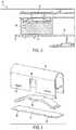
- FIG. 1shows plan view of a thin visor according to the present invention.
- FIG. 2shows a close up view of a carrier in use with the thin visor according to the present invention.
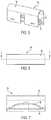
- FIG. 3shows a cross sectional view taken along line 3 - 3 of FIG. 1 according to the present invention.
- FIG. 4shows an exploded view of a detent used in the thin visor according to the present invention.
- FIG. 5shows a perspective view of a detent used in the thin visor according to the present invention.
- FIG. 6shows a top view of a detent used in the thin visor according to the present invention.
- FIG. 7shows a cross sectional view taken along line 7 - 7 of FIG. 6 according to the present invention.
- FIG. 8shows a partial cross section of a thin visor according to the present invention.
- FIG. 9shows a partial cross section of a thin visor according to the present invention.
- FIG. 10shows a partial cross sectional view of a thin visor according to the present invention.
- FIG. 11shows a vanity switch for use in a thin visor according to the present invention.
- FIG. 12shows a view of a vanity switch with the vanity door in an open position according to the present invention.
- FIG. 13shows a side view of a vanity switch with the door in an open position according to the present invention.
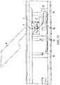
- FIG. 14shows a plan view of a thin visor according to the present invention.
- FIG. 15shows a partial front perspective of a thin visor according to the present invention.
- FIG. 16shows a cross sectional view taken along line 16 - 16 of FIG. 15 according to the present invention.
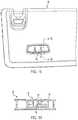
- FIG. 17shows a perspective view of a flush mounted universal opener assembly according to the present invention.
- FIG. 18shows a top view of a flush mounted universal opener assembly according to the present invention.
- FIG. 19shows a perspective view of a side mounted universal opener assembly arranged in a thin visor according to the present invention.
- FIG. 20shows a cross sectional view of a side mounted universal opener assembly according to the present invention.
- the visor 30may be a sliding visor or a non-sliding visor.
- the visor 30may be a thin visor, a standard size version or any other type or size of visor.
- the present inventionbroadly provides a dual shell or halves 32 , 34 , which form a visor body.
- the vehicle sun visor 30has a pivot rod 36 mounted to a carrier 38 , wherein the pivot rod 36 and carrier 38 are slidably captured within the visor shell portions 32 , 34 when they are secured together.
- the carrier 38thus rides in the visor body itself and in one embodiment is preferably retained via a rail 40 to one of the visor half shells 32 , 34 within the visor body. It should be noted that the retention may also include other surfaces and/or features such as channels, shelves and the like which may be molded integrally with the shell portions 32 , 34 .
- the pivot rod 36rides in the visor body via bracket 58 , bezels or similar components to support the pivot rod 36 therein. These components may be molded directly in to the visor half shells 32 , 34 .
- Other aspects of the present inventioninclude methods for manufacturing a sun visor 30 also described herein.
- the visor 30may be used in any known type of vehicle, such as but not limited to automotive vehicles, maritime vehicles, aerospace vehicles, military vehicles, and any other known vehicle that may have a need for the sun to be blocked from filtering into the interior compartment of the vehicle.
- generally all of the components of the sliding thin visor 30may be made of a plastic material that is capable of either being extruded, molded, or shaped by any known manufacturing process.
- any other known metal, ceramic, plastic, composite, natural material or any other known materialmay also be used for any of the parts or components of the sliding thin visor 30 described herein.
- the sliding thin visor 30includes a first and second halves or shells 32 , 34 that are engagable to form the elongate visor body.
- Various molded featuresmay be included on each shell to facilitate engagement of the shells 32 , 34 .
- complimentary structuresmay be formed on the respective visor shells that allow a snap fit therebetween.
- the shells 32 , 34may be formed having the two visor shells 32 , 34 made of separate substrate halves and then combined together and closed with respect to one another and vibration welded together to form the visor body as shown in the drawings.
- the shells 32 , 34may be formed by having an integral or connected longitudinal peripheral edges respectively.
- the visor 30further includes a pivot rod 36 that is arranged into one end of the visor body and connected on the opposite end to a headliner or roof of the vehicle to which the sun visor 30 is arranged.
- the sliding thin visor 30is preferably formed such that the shells 32 , 34 may be closed about the pivot rod 36 and as such capture the pivot rod 36 therebetween.
- the sliding thin visor 30may include a carrier 38 which is slidably captured within one or between both of the shells 32 , 34 via a rail mechanism 40 arranged from an inside surface of one shell or via any other methodology. All of the component parts of the sliding thin visor 30 may be manufactured from known materials and by known processes, such as but not limited to any type of plastic, metal, ceramic, composite, natural materials or any other known material and by any type of molding technique, forming technique, chemical or mechanical process that may be used to design and make the components as described herein.
- the shells 32 , 34are formed by injection molding of plastic material in a conventional manner.
- the shells 32 , 34may be formed from a molded polyethylene or by some other suitable method and/or material.
- the first and second shells 32 , 34generally include retaining surfaces in any known shape, such as arcuate retaining surfaces, flat or angle retaining surfaces, all of which may be elongate, or trough shaped surfaces extending parallel to an edge of the visor shells 32 , 34 and defining a portion of a visor wall. It should further be appreciated that the present invention may encompass designs with retaining surfaces that vary in dimension between longer, trough shaped features and more narrow arcuate ledges as shown in the figures.
- one of the shells 32 , 34may have a rail 40 extending from a predetermined inside surface thereof and extending in a longitudinal direction. It should be noted that the rail 40 may extend a predetermined distance along the inside surface of one of the visor half shells 32 , 34 . In one contemplated embodiment, the rail 40 may generally have an L-shape when viewed in cross section and extend from the inside surface of one of the shells 32 , 34 .
- One of the visor shells 32 , 34may also include a shelf 42 that extends out from an interior wall thereof, wherein the shelf 42 extends a predetermined longitudinal distance across a predetermined portion of the inside surface of one of the visor half shells 32 , 34 .
- the shelf 42generally may have a rectangular top surface that extends perpendicular from the inside surface of the visor half shell 34 and may include a plurality of different sized and shaped bracket 58 is arranged between a bottom surface of the shelf 42 and the inside surface of the visor half shell 34 .
- the carrier 38 described hereinmay have a bottom surface slide along the top surface of the shelf 42 and have the L-shaped rail 40 interengage with a flange or riding surface 46 arranged along a generally mid point of the carrier 38 .
- the rail 40 and the shelf 42 of the first shell 34 of the visor body 30are generally parallel to one another with the rail 40 being arranged above or towards the top of the visor half shell 34 with respect to the shelf 42 .
- the visor half shells 32 , 34may include other surfaces that receive and hold various components of the sliding thin visor 30 , such as but not limited to the pivot rod 36 , a D-ring, a vanity 48 , cover material 50 arranged over the visor body 30 , visor rotation switches, a vanity switch 56 , flush or side mounted universal openers 52 , a detest assembly 54 and a sliding vanity door.
- the visor half shells 32 , 34may also include any other known plurality of orifices or other surfaces, journals or bracket 58 s extending from either an inside surface, side surface or outside surface depending on the design requirements of the sliding thin visor 30 .
- the sliding thin visor 30also includes a pivot rod 36 which is attached at one end to a bracket 58 and connector 58 , which is secured to a headliner or roof of a vehicle.
- the bracket 58may have a connector secured thereto to connect the electrical system of the vehicle via a wire or other mechanism to the bracket 58 .
- the wiremay then be passed through the pivot rod 36 or traversed in another manner into the visor body.
- a solid pivot rod 36may be used and may or may not be capable of passing electricity therethrough to allow for illumination of a vanity mirror that may be arranged in the visor body.
- the visor rod 36may be hollow which may allow for a wire to pass therethrough and then provide power to a vanity 48 arranged within the visor body 30 .
- the bracket 58may be secured to the roof via fasteners or any other known methodology.
- the bracket 58may include an orifice that may receive one end of the pivot rod 36 near an elbow of the pivot rod 36 , wherein the pivot rod 36 generally has an angle of 60 to 120 degrees at the elbow.
- the pivot rod 36may be secured and capable of rotation within the orifice of the bracket 58 and may also be swung between a front windshield of the vehicle and a side window of the vehicle to block the sun from any angle.
- the pivot rod 36may be of any known length and diameter depending on the design of the visor 30 and the automobile into which it is arranged.
- the wireis connected from the electrical system of the automobile and is passed through to an LED or other lighting mechanism for illumination of a visor mirror in the vanity 48 .
- the visor 30 , pivot rod 36 and bracket 58may be made of any known material such as but not limited to plastic, ceramic, composites, metals, natural materials, etc.
- the visor rod 36may also include a predetermined notch 60 arranged near one end thereof, wherein that notch 60 generally has the form of a rectangular cutout arranged on a predetermined surface of the visor rod 36 . It is also contemplated to use a visor pivot rod 36 that does not have a notch 60 surface arranged thereon.
- the visor pivot rod 36is arranged within a carrier 38 , which is positioned on the shelf 42 and interengaged with the rail 40 of one of the visor half shells 32 , 34 according to the present invention.
- the carrier 38also includes a first and second cavity 62 arranged on one side thereof, wherein the cavities 62 generally have a rectangular shape and may include a ledge 64 arranged therein.
- the carrier 38generally has a rectangular shape, however any other shape may also be used.
- a first and second arm 66may extend from a top thereof and at both corners thereof.
- the arms 66generally have a circular orifice near a top thereof.
- the orificesreceive the pivot rod 36 therethrough.
- a wall or panel 68is arranged between the arms 66 and generally has a square or rectangular shape.
- the wall 68is arranged on each side and from a top of the carrier 38 .
- the carrier 38also may include a first and second leg 70 extending from a bottom surface thereof, wherein the first and second leg 70 are parallel to one another and generally are rectangular in shape and extend the entire length of the carrier 38 . It should be noted that the legs 70 extend a predetermined distance from the bottom of the carrier 38 .
- the carrier 38may also include a generally square shaped riding surface or flange 46 arranged at a general mid point thereof in a side of the carrier 38 opposite that of the first and second cavity 62 .
- the flange 46generally has a square shape when looked in cross section and generally may mimic the shape of a cavity 62 or gap formed by the rail 40 , which is arranged from an inner surface of one of the visor half shells 32 , 34 . Hence, the flange 46 may ride within the gap formed by the rail 40 , thus slidingly securing the carrier 38 to the visor half shell 34 via the rail 40 .
- first and second leg 70 extending from the bottom surface of the carrier 38may interengage with a top surface of the shelf 42 arranged from an inner surface of one of the visor half shells 32 , 34 thus allowing for engagement of the carrier 38 to the visor half shell 34 via the first and second leg 70 and the flange 46 interengaging with the rail 40 of the visor half shell 34 .
- Thismay ensure that the carrier 38 is secured to the visor half shell 34 in a sliding manner, which allows for the visor carrier 38 to slide along the rail 40 a predetermined longitudinal distance prescribed by the length of the pivot rod 36 , rail 40 and shelf 42 arranged therein.
- the top portion of the carrier 38includes a pocket that is generally defined by the first and second arm 70 and the walls 68 arranged from each side of the carrier 38 . Extending in an upward direction from an inside surface of the pocket may be a plurality of ribs 72 which may be used to support a bottom plate 74 of a detent 54 which is arranged therein. It should be noted that the first and second cavity 62 arranged on one side of the carrier 38 may or may not include art orifice that passes through the carrier 38 until it reaches or goes through the flange 46 arranged on the opposite side of the carrier 38 . The plurality of ribs 72 that extend from a bottom surface of the pocket of the carrier 38 may engage with a bottom plate 74 of the detent 54 as described above.
- the detent assembly 54generally includes a housing 76 having a generally U-shaped trough design, i.e., that of a mailbox, a spring 78 having a generally recurve bow shape arranged within the housing 76 of the detent 54 and a bottom plate 74 secured to or near a bottom of the housing 76 of the detent 54 in order to allow for the spring 78 to be arranged therein.
- the bottom plate 74has a rectangular shape with a plurality of tabs 80 extending therefrom. In one embodiment shown, four tabs 80 extend from the bottom plate 74 from a side edge thereof.
- the housing 76 having a generally U-shape or mailbox shapemay include at least one slot 82 and preferably four slots 82 .
- the slots 82may be arranged near each bottom end on each side of the housing 76 wherein those slots 82 may mimic the location of and may interact with and receive the tabs 80 on the bottom plate 74 to allow for the bottom plate 74 to be secured to the housing 76 of the detent 54 .
- the slots 82generally have a rectangular shape which may mimic that of the rectangular tabs 80 extending from the side surfaces of the bottom plate 74 . It should be noted that the location and shape/size of the tabs 80 and slots 82 in the bottom plate 74 and housing 76 respectively, may be anywhere along the housing 76 or bottom plate 74 depending on the design requirements of the visor 30 .
- the housing 76has two open ends such that the housing 76 generally forms a saddle shape and also includes a first notch 84 arranged on a first side thereof and a second notch 84 arranged on a second side thereof, wherein the notches 84 generally have a rectangular shape and extend from a bottom edge of the housing 76 a predetermined distance up into the side wall of the housing 76 . This distance may be adjusted depending on the design requirements and the spring 78 used in the detent 54 assembly.
- the spring 78generally as described above has a recurve bow shape and may also include a first tab 86 extending from a near mid point or mid point thereof on a first side thereof and a second tab 86 extending from a near mid point or midpoint on a second side thereof.
- This first and second tab 86 extending from the spring 78may allow for the first and second tab 86 to be aligned with and slide within the first and second notch 84 arranged within the housing 76 of the detent 54 assembly. This may allow for the spring 78 to flex in a downward or upward motion with the downward motion being towards the bottom plate 74 when the spring 78 engages certain surfaces of the pivot rod 36 .
- the detent 54may have the pivot rod 36 pass through the top curved portion of the housing 76 and engage a top surface of the spring 78 when the carrier 38 and detent 54 assembly is arranged within the visor half shell 34 and the pivot rod 36 is arranged therethrough.
- the detent 54 assemblymay be used to secure the pivot rod 36 to the visor body 30 via the spring 78 engaging with an upward force against an outer surface of the pivot rod 36 such that the pivot rod 36 may be pinched between an inner surface of the housing 76 and/or arms 66 and a top surface of the spring 78 thus allowing for a secure connection between the pivot rod 36 and the visor body 30 .
- the visor pivot rod 36may have a predetermined flat cutout portion 60 which may be arranged at or near an end of the visor pivot rod 36 .
- This cutout portion 60may allow for the detent assembly spring 78 to interact with the flat cutout portion in order to stop the visor body from sliding with respect to the pivot rod 36 when it reaches this flat surface 60 , thus creating a hard stop to ensure that the visor body 30 does not slide off of the pivot rod 36 during use by the consumer in the vehicle.
- the shape of the spring 78may allow for the efforts and force necessary to slide and rotate the visor body with respect to the pivot rod 36 .
- all of the parts of the detent 54 assemblyare made of a metal material, however any other plastic, ceramic, composite, or natural material may also be used for the detent 54 assembly components. It should also be noted that any other shape may also be used for the spring 78 .
- a wire routing optionmay be arranged therein and may have a wire routing system used in conjunction therewith.
- the sliding thin visor 30may also include a vanity member 48 .
- the vanity member 48generally may include a vanity door 88 , door springs 92 , a vanity frame 90 , a vanity mirror 94 with optional lights arranged therein or nearby. If the vanity 48 is illuminated, the vanity 48 may also include at least one lens to disburse light in a predetermined manner or a light guide/specialized mirror to perform such light dispersion.
- the vanity frame 90may include at least one connecting flange.
- the vanity 48may include a plurality of fasteners or tabs or locking surfaces extending therefrom which may be used to interact with reciprocal locking surfaces, shoulders, or other components arranged in one of the visor half shells 32 , 34 , such that the vanity 48 is arranged and secured within a predetermined orifice through one of the visor body half shells 32 , 34 . It should be noted that any known means for securing the vanity 48 within one of the visor half shells 32 , 34 may be used. If the vanity 48 does have illumination options, the vanity 48 may include a vanity door 88 , which generally is pivotally connected to the vanity frame 90 via an arm, door springs or the like.
- the door 88may be capable of rotating or pivoting between a closed position, wherein the vanity door 88 is flat compared to an outside surface of the visor body 30 and an open position wherein the vanity door 88 is not in a flat position with respect to the visor body such that the door 88 moves in a rotational manner such that the vanity mirror 44 is fully viewable by the user of the vanity 48 .
- the vanity door 88may include a first and second door arm or journal 96 extending from a top surface thereof, wherein that door arm 96 generally may have a C-shape or any other shape when viewed from the side. However, it should be noted that the C-shaped arm 96 may only extend from one end or near the middle of the vanity door 88 , depending on the design requirements.
- the vanity door 88may have a post or rod extending from a predetermined position.
- the post or rodare rotatably secured within the vanity frame 90 and allows for the vanity door 88 to rotate with respect to the vanity frame 90 , thus allowing for the vanity mirror 94 to become visible when the door 88 is in an open position to the user of the vanity.
- a first contactextends at a right angle from the C-shaped journal 96 . It should be noted that any known shape may be used for the journal 96 on the end of the vanity door 88 .
- the first contact 98is an electrical contact that is arranged within either an orifice of the generally C-shaped journal 96 of the vanity door 88 , or arranged over a post or rod which extends from the journal 98 in an outward direction with respect to an edge of the vanity door 88 .
- the first contact 98 which is an electrical contact or postmay extend in a perpendicular direction from a side surface of the journal or C-shaped arm 96 of the vanity door 88 .
- the first contactgenerally may be made of a metal material and may allow for electricity to flow between the electrical system or power system of the vehicle and a vanity light or LED arranged somewhere within the vanity 48 in order to illuminate the mirror 94 or another component/object.
- One of the visor half shells 32 , 34may have a plurality of flanges extending from an inside surface thereof, wherein one of the flanges generally is a first L-shape flange 100 that extends from an inside surface of one of the shells 32 , 34 . Extending from a side surface of the first L-shaped flange 100 may be a second L or T shaped flange 102 , wherein the second L-shaped flange 102 is generally parallel with respect to an inside surface of the visor half shell 32 , 34 .
- a first wedge shaped or triangular shaped flange 104also extends from the inside surface of the visor half shell 32 , 34 .
- a second triangular shaped or wedge shaped flange 106also extends from an inside surface of the visor half shell 32 , 34 .
- the first wedge shaped flange 104is arranged adjacent to a portion of the first L-shaped flange 100 extending from the inside surface of the visor half shell 32 , 34 , such that a predetermined gap or channel is arranged between the first L-shaped flange 100 and the first wedge flange 104 .
- the second wedge flange 106is arranged at or near a mid point between the first L-shaped flange 100 and first wedge flange 104 at a predetermined distance therefrom.
- a second contact 108may be arranged and secured within the channel formed by the first wedge flange 104 and a portion of the first L-shaped flange 100 .
- An end of the second contact 108may to be arranged on a top surface of the second wedge flange 106 in order to provide the necessary electrical connection between the vehicle and the second electrical contact 108 .
- the second contact 108has a U-shape when viewed from a side with a first end extended at a predetermined angle therefrom and a second end also extending at a predetermined angle therefrom.
- the second endhas an orifice 110 therethrough, wherein that orifice 110 may interact with the second wedge 106 , thus providing the necessary electrical connection through the visor to the electrical system of the vehicle or to the light or LED of the vanity depending on the design requirements of the visor 30
- the second contact 108is arranged around the second L-shaped flange 102 and in the gap between the first wedge flange 104 and the first L-shaped flange 100 to ensure the second contact 108 is secure with respect to the visor shell and hence the first contact 98 which is arranged from a side surface of the vanity door 88 .
- the first contact 98has a cylindrical shape and is made of a metal material that may include a predetermined diameter for the contact with a reduced diameter portion arranged between two same sized outer diameter portions.
- the first contact 98may rotate or pivot in one contemplated embodiment, approximately 45 degrees and come into contact with the first end of the second contact 108 thus completing the electrical circuit and allowing for electricity to flow between the electrical system of the vehicle and the lighting system arranged on the vanity 48 of the visor 30 .
- any other are or path of rotation between 0 and 360 degreesmay also be used.
- first contact 98may be electrically connected to either the vehicle electrical system or the light on the vanity 48 or vice versa, the same is true for the second contact 108 .
- first contact 98 and second contact 108may be made of a metal material, however any other electrically conductive material may also be used for these contacts.
- first L-shaped flange 100may also include a third flange 112 extending from a top surface thereof, wherein that third flange 112 may interengage with the second end of the second contact 108 .
- the second contact 108generally has the second L-shaped flange 102 arranged within a gap therein and the second contact 108 is connected to the electrical system of the vehicle on the second end while the first end is arranged at a predetermined angle, in one embodiment a 45 degree angle, however any other known angle from 0 to 360 degrees may be used depending on the design requirements.
- the second contact 108 first endmay be shaped and moved to any angle in order to provide power in relation to the first contact 98 arranged on the door 88 .
- the sliding thin visor 30may also include a flush mounted universal opener assembly or member 52 that may have a bezel 114 arranged on the top outer surface of the visor body.
- buttons 116 of the flush mounted universal opener 52generally are molded into one of the visor half shell substrates 32 , 34 . These buttons 116 are molded therein such that they are inset, and recessed below the outer surface of the visor body. Hence, they are inset into the outer surface of one of the visor body half shells 32 , 34 .
- the universal opener assembly 52generally may be arranged on the outer surface of the visor half shell which is visible to the user when the visor 30 is in its up or stored position against the headliner of the vehicle.
- the universal opener assembly 52may be arranged at or near one of the edges through a side surface of the visor body 30 .
- the visor body half shell 32 , 34may have an orifice arranged therethrough that generally may mimic the outer shape of the universal opener assembly 52 .
- a generally rectangular shape with fanned out top edgesis used.
- any other known orifice and shapemay be used for the universal opener assembly 52 of the sliding thin visor or regular visor 30 according to the present invention.
- the buttons 116 of the universal opener assembly 52maybe integrated or molded directly into one of the visor half shells 32 , 34 .
- At least one flexible button 116 and in the embodiment shown three flexible buttons 116are arranged inset from a surface of one of the visor half shells 32 , 34 .
- the buttons 116have a square or rectangular shape with an orifice arranged therethrough at or near a midpoint thereof.
- the orificesmay be of any known shape within the visor buttons 116 .
- the three visor buttons 116 as shown in the drawings,are all attached only on one edge thereof to the visor shell 32 , 34 . It is also contemplated that a plurality of orifices may be arranged at the intersection between the edge of the orifice of the visor half shell 32 , 34 and the connecting surfaces to the three buttons 116 of the universal opener assembly 52 .
- the orificesmay not be arranged along that connecting edge.
- the attachment of the three buttons 116 on one side surface thereofallows for the buttons 116 to be flexible and have a predetermined spring action. This may allow for the buttons 116 to be moved in a inward direction towards an opener module 118 that is arranged within the visor body 30 and then return to a home position upon release thereof.
- the universal opener module 118is arranged such that it is directly adjacent to and below the orifice through one of the visor half shells 32 , 34 .
- the visor half shell 32 , 34may have a circular or other shaped light orifice 120 arranged directly adjacent to the opener orifice in order to allow for light to pass through the outer covering 50 of the visor 30 to show when the universal opener assembly 52 is in use, etc.
- the flexible buttons 116may be molded directly into one of the visor half shells 32 , 34 and may allow for the flexible buttons 116 to be pushed in a downward direction towards the interior of the visor body and then return back to its normal holding position via a spring action which is designed into the plastic material that is used in the molding process.
- a post 122extends from a bottom surface of each of the three buttons 116 , wherein the post 122 generally has a circular shape and extends a predetermined distance from the bottom surface thereof.
- the post 122may interact with a switch 124 arranged on the universal opener module 118 which is secured and held in a predetermined position within the visor body 30 .
- the suppression or pushing of the button 116may allow for the pest 122 to interact with the switch 124 on the universal door opener module 118 , thus allowing for a signal to be sent to either a garage door, lights or other components within a house or arranged near a vehicle.
- buttons 116 of the universal door opener assembly 52may be used for the orifice and buttons 116 of the universal door opener assembly 52 described herein. It should further be noted that any other connection methodology other than direct molding of the buttons 116 on a surface of an orifice of one of the visor half shells 32 , 34 may also be used.
- buttons 116which are inset on the outer surface of one of the visor half shells 32 , 34 and then place placards, screen prints or stickers identifying where the buttons 116 are arranged underneath the cloth and then have the user push directly on the outer cover on the placard or stickers arranged on the outside surface thereof in order to activate the buttons 116 of the universal door opener assembly 52 .
- the three buttons 116 as shown in the figuresextend from an inset edge which generally defines the orifice into which the buttons 116 are arranged. As noted, these buttons 116 are recessed below the outer surface of the shell 32 , 34 .
- the orificeis formed within a slight indentation such that a small pocket is formed in the outer surface of one of the visor half shells 32 , 34 by an angled surface which ends at the inner edge and in turn defines the shape of the orifice.
- the downward angle at which the pocket is formedmay be adjusted depending on the design requirements.
- the bezel 114generally has a shape that mimics that of the three buttons 116 .
- the bezel 114has three separate tongue members which correspond to the three flexible buttons 116 and allow for the bezel 114 to be arranged on the outer surface of one of the visor half shells 32 , 34 .
- the bezel tongue membersmay have any known shape as long as it mimics that of the buttons 116 that are arranged directly thereunder. Extending from a bottom surface of the bezel tongues is a flange 130 . Generally, the flange 130 has a locking member 132 extending from a surface thereof, wherein the flange 130 generally has either a square or circular shape, however any other shape may be used. These flanges 130 may be hollow or solid depending on the design requirement.
- the locking member 132may be a triangular shaped wedge extending from an outside surface of the flange 130 , thus allowing for interaction and interengagement between the locking member 132 that extends from the outside surface of at least one of the flanges 130 of the bezel 114 and a surface of a button 116 adjacent to the post or peg 122 that extends from a bottom surface thereof. It should be noted that there may be only one flange 130 extending from one of the buttons 116 or a flange 130 extending from each of the three buttons 116 and a locking member 132 extending from one or all of the flanges 130 that extend from the bottom surface of the bezel 114 .
- buttons 116have been described herein, however any other number of buttons 116 from one to ten may also be included in the flush universal door mounting assembly 116 according to the present invention.
- buttons 116 as described abovemay be placed on the side of the visor 30 along the edge and when a button 116 is pressed inward the button 116 may contact and interact with the universal door opener module 118 which may be arranged therein.
- any number of buttons 116may be used and the buttons 116 may have any known shape such as square and rectangular as shown in the drawings, and may also include a post that extends from a bottom surface thereof that may interact with the universal door opener module 118 arranged and secured directly adjacent thereto.
- generally all of the components of the flush mount universal door opener assembly 52are made of a plastic material, however any other metal, ceramic, plastic, composite, natural material or any other known material may also be used for any of the components described herein.
Landscapes
- Engineering & Computer Science (AREA)
- Mechanical Engineering (AREA)
- Arrangements Of Lighting Devices For Vehicle Interiors, Mounting And Supporting Thereof, Circuits Therefore (AREA)
- Vehicle Step Arrangements And Article Storage (AREA)
Abstract
Description
Claims (18)
Priority Applications (7)
| Application Number | Priority Date | Filing Date | Title |
|---|---|---|---|
| US16/288,579US10864804B2 (en) | 2019-02-28 | 2019-02-28 | Sliding thin visor |
| PCT/US2020/019403WO2020176371A1 (en) | 2019-02-28 | 2020-02-24 | Sliding thin visor |
| CA3128203ACA3128203A1 (en) | 2019-02-28 | 2020-02-24 | Sliding thin visor |
| JP2021547366AJP2022523343A (en) | 2019-02-28 | 2020-02-24 | Sliding thin visor |
| MX2021008894AMX2021008894A (en) | 2019-02-28 | 2020-02-24 | Sliding thin visor. |
| CN202080016375.0ACN113573924A (en) | 2019-02-28 | 2020-02-24 | Sliding thin sun visor |
| EP20763459.3AEP3931014A4 (en) | 2019-02-28 | 2020-02-24 | Sliding thin visor |
Applications Claiming Priority (1)
| Application Number | Priority Date | Filing Date | Title |
|---|---|---|---|
| US16/288,579US10864804B2 (en) | 2019-02-28 | 2019-02-28 | Sliding thin visor |
Publications (2)
| Publication Number | Publication Date |
|---|---|
| US20200276887A1 US20200276887A1 (en) | 2020-09-03 |
| US10864804B2true US10864804B2 (en) | 2020-12-15 |
Family
ID=72236894
Family Applications (1)
| Application Number | Title | Priority Date | Filing Date |
|---|---|---|---|
| US16/288,579ActiveUS10864804B2 (en) | 2019-02-28 | 2019-02-28 | Sliding thin visor |
Country Status (7)
| Country | Link |
|---|---|
| US (1) | US10864804B2 (en) |
| EP (1) | EP3931014A4 (en) |
| JP (1) | JP2022523343A (en) |
| CN (1) | CN113573924A (en) |
| CA (1) | CA3128203A1 (en) |
| MX (1) | MX2021008894A (en) |
| WO (1) | WO2020176371A1 (en) |
Cited By (4)
| Publication number | Priority date | Publication date | Assignee | Title |
|---|---|---|---|---|
| US11396220B2 (en) | 2014-12-16 | 2022-07-26 | Irvin Automotive Products, LLC | Visor |
| US20220289003A1 (en)* | 2019-09-06 | 2022-09-15 | Kyowa Sangyo Co., Ltd. | Vehicle sun visor |
| US11820310B1 (en)* | 2017-06-30 | 2023-11-21 | Apple Inc. | Panel intrusion control |
| US12077123B2 (en)* | 2017-10-20 | 2024-09-03 | Dalphi Metal Espana, S.A. | Vehicle passenger restraint system comprising an airbag |
Families Citing this family (2)
| Publication number | Priority date | Publication date | Assignee | Title |
|---|---|---|---|---|
| EP3189995B1 (en) | 2015-12-16 | 2019-11-13 | Motus Integrated Technologies | Slide-on-rod assembly for a vehicle sun visor |
| USD1033062S1 (en)* | 2023-10-27 | 2024-07-02 | Shenzhen Smile Technology Co., Ltd. | Mirror |
Citations (176)
| Publication number | Priority date | Publication date | Assignee | Title |
|---|---|---|---|---|
| US3710674A (en) | 1970-12-18 | 1973-01-16 | Meteor Res Ltd | Expandable fastener |
| US3926470A (en) | 1973-03-21 | 1975-12-16 | Prince Corp | Visor assembly |
| US4000404A (en) | 1973-03-21 | 1976-12-28 | Prince Corporation | Visor illuminated mirror |
| US4174864A (en) | 1977-01-28 | 1979-11-20 | Gebr. Happich Gmbh | Lighted sun visor for vehicles |
| US4227241A (en) | 1978-10-23 | 1980-10-07 | Prince Corporation | Visor assembly |
| US4479172A (en) | 1981-11-13 | 1984-10-23 | Clearplas Ltd | Illuminated mirror assembly |
| US4521046A (en) | 1982-02-09 | 1985-06-04 | Lear S.N.C. Di Foggini & C. | Cell structure sun visor for automobile vehicles including retention and snap-action positioning means |
| US4533275A (en) | 1980-07-16 | 1985-08-06 | Lear S.N.C. | Swivel connector for securing motorvehicle sun visors |
| US4598943A (en) | 1983-10-26 | 1986-07-08 | Daimler-Benz Aktiengesellschaft | Vehicle sun visor |
| US4617699A (en) | 1981-06-19 | 1986-10-21 | Nissan Motor Co., Ltd. | Hinge structure for a sun visor or the like which features a single storage position snap action function |
| US4679843A (en) | 1984-12-26 | 1987-07-14 | Prince Corporation | Visor mounting clip |
| US4715644A (en) | 1986-09-22 | 1987-12-29 | Irvin Industries, Inc. | Spring-loaded hinge assembly for vehicle accessories |
| US4729590A (en) | 1987-03-23 | 1988-03-08 | Prince Corporation | Visor rod mount |
| US4756570A (en) | 1987-05-21 | 1988-07-12 | General Motors Corporation | Sunshade support assembly |
| US4760503A (en) | 1986-09-26 | 1988-07-26 | Prince Corporation | Visor for a vehicle |
| US4879637A (en) | 1988-11-04 | 1989-11-07 | Prince Corporation | Light control circuit for vanity mirror assembly |
| US4925233A (en) | 1987-12-28 | 1990-05-15 | Prince Corporation | Adjustable visor |
| US4973020A (en) | 1988-04-06 | 1990-11-27 | Rockwell-Cim Societe Anonyme | Mirror housing for a sunshade |
| US4993772A (en) | 1990-02-20 | 1991-02-19 | Irvin Automotive Products, Inc. | Spring-loaded, dual-action hinge assembly for vehicle accessories |
| US4997228A (en) | 1989-07-24 | 1991-03-05 | Prince Corporation | Multiple function visor |
| US4998765A (en) | 1989-02-21 | 1991-03-12 | Prince Corporation | Sliding visor |
| US5011211A (en) | 1988-04-29 | 1991-04-30 | Autopart Sweden Ab | Sun visor for motor vehicles |
| US5054839A (en)* | 1990-08-31 | 1991-10-08 | White Jay E | Vehicular sun visor assembly |
| US5059016A (en) | 1990-08-09 | 1991-10-22 | United Technologies Automotive | Vanity mirror assembly |
| US5078445A (en) | 1986-09-26 | 1992-01-07 | Prince Corporation | Visor |
| US5082322A (en) | 1991-02-28 | 1992-01-21 | Prince Corporation | Visor rod mount |
| US5161850A (en) | 1991-09-10 | 1992-11-10 | Prince Corporation | Sliding visor |
| US5184867A (en) | 1991-01-31 | 1993-02-09 | Rockwell Automotive Body Systems-France | Sun-visor with covering and supporting arm |
| US5230546A (en) | 1992-08-25 | 1993-07-27 | Prince Corporation | Vanity mirror visor cover |
| US5232192A (en) | 1991-05-22 | 1993-08-03 | Kabushiki Kaisha Kokuho | Suspender arm for machinery |
| US5331518A (en) | 1992-09-22 | 1994-07-19 | Prince Corporation | Visor mirror cover assembly |
| US5340186A (en) | 1991-06-04 | 1994-08-23 | Fico I.T.M. S.A. | Attachment device for sunvisor vanity mirrors |
| US5409285A (en) | 1994-04-18 | 1995-04-25 | Prince Corporation | Sliding visor |
| US5428513A (en) | 1993-11-17 | 1995-06-27 | Prince Corporation | Covered vanity mirror and flexible circuit |
| US5445427A (en) | 1993-12-06 | 1995-08-29 | Vandagriff; Craig A. | Pivotable sun visor attachment |
| US5486033A (en) | 1993-11-13 | 1996-01-23 | Gebr. Happich Gmbh | Support shaft for a vehicle sun visor |
| US5544928A (en) | 1993-12-20 | 1996-08-13 | Toyota Jidosha Kabushiki Kaisha | Mounting structure of sun visor for automobile |
| US5556154A (en) | 1994-10-25 | 1996-09-17 | Gebr. Happich Gmbh | Visor with two-part core |
| US5575552A (en) | 1994-12-09 | 1996-11-19 | United Technologies Automotive Systems, Inc. | Lighted mirror apparatus |
| US5580118A (en) | 1995-08-14 | 1996-12-03 | Crotty, Iii; Willard E. | Sun visor having an alignment element |
| US5580117A (en) | 1995-05-18 | 1996-12-03 | Goclowski; Keith M. | Attachable and extendible sun visor for increased and convenient sun protection in an automobile |
| US5645308A (en) | 1995-08-29 | 1997-07-08 | Prince Corporation | Sliding visor |
| US5653490A (en) | 1996-04-12 | 1997-08-05 | Prince Corporation | Sliding visor |
| US5660424A (en) | 1993-11-25 | 1997-08-26 | Fico I.T.M., S.A. | Sunvisor with impact-breakable support |
| US5685629A (en) | 1994-09-29 | 1997-11-11 | Prince Corporation | Vanity mirror assembly |
| JPH10151944A (en) | 1996-11-25 | 1998-06-09 | Kasai Kogyo Co Ltd | Sun visor for automobile and manufacture thereof |
| US5820197A (en) | 1997-04-11 | 1998-10-13 | Prince Corporation | Visor torque control |
| US5823603A (en) | 1995-08-14 | 1998-10-20 | Crotty Corporation | Modular sun visor assembly and method of assembling a sun visor |
| US5855443A (en) | 1997-05-16 | 1999-01-05 | Board Of Regents Of University Of Nebraska | Breakaway connection system for roadside use |
| US5951091A (en) | 1998-05-19 | 1999-09-14 | Prince Corporation | Adjustable visor |
| US5967587A (en) | 1997-03-18 | 1999-10-19 | Prince Corporation | Sliding visor |
| US5967588A (en) | 1997-04-11 | 1999-10-19 | Prince Corporation | Visor control |
| US6010174A (en) | 1997-04-14 | 2000-01-04 | Lear Automotive Dearborn, Inc. | Sliding visor |
| US6010175A (en) | 1997-05-28 | 2000-01-04 | Bodar; Andre | Sun visor for vehicles |
| US6012757A (en) | 1998-07-24 | 2000-01-11 | Becker Group Europe Gmbh | Sun visor for vehicles |
| US6024399A (en) | 1997-07-22 | 2000-02-15 | Viertel; Lothar | Sun visor for vehicles |
| US6059348A (en) | 1997-12-09 | 2000-05-09 | Becker Group Europe, Gmbh | Sun visor shaft |
| US6131985A (en) | 1995-08-14 | 2000-10-17 | Crotty Corporation | Modular sun visor assembly and method of assembling a sun visor |
| US6135610A (en) | 1995-07-01 | 2000-10-24 | Becker Group Europe Gmbh | Electrical plug connection in a sun visor for motor vehicles |
| US6139083A (en) | 1998-04-24 | 2000-10-31 | Lear-Donnelly Overhead Systems, Llc | Sliding core visor |
| US6174019B1 (en) | 1998-02-26 | 2001-01-16 | Prince Corporation | Extruded visor control |
| US6189949B1 (en) | 1998-01-05 | 2001-02-20 | Lear Donnelly Overhead Systems L.L.C. | Visor with extender blade and guide therefor |
| US6220644B1 (en) | 1999-03-10 | 2001-04-24 | Lear Automotive Dearborn, Inc. | Visor assembly |
| US6264352B1 (en) | 2000-02-15 | 2001-07-24 | Lear Corporation | Sun visor and vanity mirror assembly for motor vehicles |
| US6264264B1 (en) | 1999-03-04 | 2001-07-24 | Nifco Inc. | Rotary damper device and sun visor attaching apparatus by using the same |
| US20010024048A1 (en) | 2000-02-29 | 2001-09-27 | Hobson James (Jud) | Sun visor assembly with non-expanding adhesive |
| JP2001322428A (en) | 2000-05-16 | 2001-11-20 | Neoex Lab Inc | Sun visor for vehicle |
| US6325443B1 (en) | 2001-01-26 | 2001-12-04 | Marilu Sanchez | Visor extension device |
| US20010050493A1 (en) | 2000-04-05 | 2001-12-13 | Patrick Welter | Visor for vehicles |
| US6334626B2 (en) | 1997-09-26 | 2002-01-01 | Toyota Jidosha Kabushiki Kaisha | Interior equipment mounting structure for a vehicle incorporating head-protecting air bag body |
| US6368114B1 (en) | 1998-12-17 | 2002-04-09 | Autonetworks Technologies, Ltd. | Electrical wiring structure for sunvisor |
| US6371546B1 (en) | 1998-07-16 | 2002-04-16 | Samuel Alexander Jefferson | Telescopic sun screen assembly |
| US6382697B1 (en) | 2000-11-29 | 2002-05-07 | Innotec Corporation | Stamping reinforced polymeric molded elbow and method of manufacture |
| US6439638B1 (en) | 1999-08-20 | 2002-08-27 | Kasai Kogyo Co., Ltd. | Vehicle sun visor |
| US6464381B2 (en) | 2000-02-26 | 2002-10-15 | Federal-Mogul World Wide, Inc. | Vehicle interior lighting systems using electroluminescent panels |
| US6474717B2 (en) | 2000-04-22 | 2002-11-05 | Johnson Controls Technology Company | Visor for vehicles |
| US6475937B1 (en) | 2000-03-17 | 2002-11-05 | Patent Holding Company | Lightweight, thermoplastic, vehicle headliner having at least one integrally-formed, energy-absorbing, head-impact mechanism and injection molding method for making same |
| US6494521B2 (en) | 1999-04-16 | 2002-12-17 | William J. Hennessey | Head impact energy absorbing sun visor pivot rod connection interface cover |
| US6499868B1 (en) | 2000-01-18 | 2002-12-31 | Prestolite Wire Corporation | Vanity mirror lamp assembly with replaceable battery |
| US6511029B2 (en) | 2000-03-15 | 2003-01-28 | Yazaki Corporation | Bracket for mounting an accessory on vehicle body |
| US6547308B2 (en) | 2001-01-04 | 2003-04-15 | Johnson Controls Technology | Visor mounting assembly |
| US6604773B2 (en) | 2001-06-01 | 2003-08-12 | Honda Giken Kogyo Kabushiki Kaisha | Sun-visor of a vehicle equipping an occupant restraint system |
| US6604772B2 (en) | 2001-11-09 | 2003-08-12 | Lear Corporation | Extender blade mounting frame for a sun visor |
| US6612637B1 (en) | 2002-08-08 | 2003-09-02 | Crotty Corporation | Sliding sun visor assembly |
| US6637799B1 (en) | 2002-07-11 | 2003-10-28 | Lear Corporation | Modular sun visor and method of assembling same |
| US6659528B1 (en) | 2002-09-18 | 2003-12-09 | Lear Corporation | Method and apparatus for sliding and rotating a vehicle sun visor |
| US6669859B1 (en) | 2003-01-17 | 2003-12-30 | Lear Corporation | Inverted sun visor mirror assembly |
| US6676129B2 (en) | 2001-04-12 | 2004-01-13 | Lear Corporation | Sun visor arm connection assembly and arrangement |
| US6679538B1 (en) | 2002-10-04 | 2004-01-20 | Lear Corporation | Energy managing sun visor mounting arrangement |
| US6685257B1 (en) | 2002-04-18 | 2004-02-03 | Johnson Controls Technology Company | Extrusion for the siderail of a vehicle to provide head impact countermeasure and support for siderail components |
| US6692060B1 (en) | 2002-09-18 | 2004-02-17 | Lear Corporation | Lighted visor mirror assembly and method |
| US6692059B1 (en) | 2002-10-02 | 2004-02-17 | Grupo Antolin Ingenieria, S.A. | Sun visor with clam shell core attachment snaps |
| US6698815B1 (en) | 2002-10-02 | 2004-03-02 | Grupo Antolin Ingenieria, S.A. | Sun visor with mirror assembly |
| US6698814B1 (en)* | 2002-10-02 | 2004-03-02 | Grupo Antolin Ingenieria, S.A. | Slidable sun visor |
| US6707674B1 (en) | 2002-11-07 | 2004-03-16 | Dell Products L.P. | Dual spring heat sink retention |
| US20040145209A1 (en) | 2003-01-24 | 2004-07-29 | Peterson Donald M. | Slidable sun visor assembly |
| US6799795B1 (en) | 2003-11-11 | 2004-10-05 | Lear Corporation | Sun visor arm with notched break points |
| US6830280B2 (en) | 2003-01-17 | 2004-12-14 | Lear Corporation | Leaf spring visor detent assembly |
| US6840561B2 (en) | 2002-10-02 | 2005-01-11 | Grupo Antolin Ingeniera, S.A. | Sun visor and cover attachment method |
| US20050034555A1 (en) | 1999-11-23 | 2005-02-17 | Staker William C. | Electronic pedal assembly and method for providing a tuneable hysteresis force |
| US6860546B1 (en) | 2003-11-11 | 2005-03-01 | Lear Corporation | Two piece pivoting visor arm |
| US6863332B2 (en) | 2002-09-05 | 2005-03-08 | Honda Giken Kogyo Kabushiki Kaisha | Automobile sun visor |
| US6871990B2 (en) | 2002-05-17 | 2005-03-29 | Stanley Electric Co., Ltd. | Vehicle lamp with visor |
| US6910725B1 (en) | 2004-02-11 | 2005-06-28 | Innotec Corporation | Sliding visor |
| US6921121B2 (en) | 2003-08-21 | 2005-07-26 | Autoliv Asp, Inc. | Sun visor assembly to be used with an overhead airbag |
| US6948736B2 (en) | 2003-08-21 | 2005-09-27 | Autoliv Asp, Inc. | Sun visor attachment for an overhead airbag |
| US6957841B1 (en) | 2004-04-19 | 2005-10-25 | Lear Corporation | Expanded polypropylene sun visor assembly |
| US6962385B2 (en) | 2003-10-15 | 2005-11-08 | Irvin Automotive Products, Inc. | Sliding visor |
| US7000972B2 (en) | 2004-03-02 | 2006-02-21 | Kyowa Sangyo Co., Ltd. | Sun visor for use with vehicles |
| US20060061008A1 (en) | 2004-09-14 | 2006-03-23 | Lee Karner | Mounting assembly for vehicle interior mirror |
| US7025399B1 (en) | 2004-07-19 | 2006-04-11 | Grupo Antolin North America, Inc. | Sun visor assembly |
| US7032949B1 (en) | 2004-12-08 | 2006-04-25 | General Motors Corporation | Sun visor assembly |
| US7036877B2 (en) | 2003-09-09 | 2006-05-02 | Grupo Antolin N.A. | Modular mounting assembly |
| US7036965B2 (en) | 2003-04-16 | 2006-05-02 | Star Headlight And Lantern Co., Inc. | Light bar providing illumination from inside a vehicle |
| US7055884B2 (en) | 2004-10-25 | 2006-06-06 | Lear Corporation | Low-friction sleeve insert for a visor bearing |
| US7059652B2 (en) | 2003-10-16 | 2006-06-13 | Hayashi Telempu Co., Ltd. | Automobile sun visor stay that maintains safety in emergencies |
| US7086681B2 (en) | 2002-05-08 | 2006-08-08 | Fico I.T.M., S.A. | Coated sun visor |
| US20060175861A1 (en) | 2005-02-08 | 2006-08-10 | Honda Motor Co., Ltd. | Sun visor for vehicle |
| US7090281B2 (en) | 2001-07-25 | 2006-08-15 | Intier Automotive Inc. | Sliding sun visor |
| US7108308B2 (en) | 2004-12-13 | 2006-09-19 | Grupo Antolin-Ingenieria, S.A. | Safety mirror support for sun visors |
| US7213865B2 (en) | 2004-04-23 | 2007-05-08 | Kyowa Sangyo Co., Ltd. | Blow molded vehicle sun visors and methods of manufacturing such sun visors |
| US7217017B2 (en) | 2003-08-25 | 2007-05-15 | Johnson Controls Technology Company | Vanity for a vehicle |
| US7281751B2 (en) | 2002-10-02 | 2007-10-16 | Johnson Controls Technology Company | Sliding visor |
| US7311427B2 (en) | 2002-11-20 | 2007-12-25 | Johnson Controls Technology Company | Covered illuminated vanity mirror assembly |
| US7320493B2 (en) | 2004-10-12 | 2008-01-22 | Piolax, Inc. | Sun visor |
| US7338108B2 (en) | 2005-06-28 | 2008-03-04 | Kyowa Sangyo Co., Ltd. | Sun visor for vehicles |
| US20080093876A1 (en)* | 2004-08-30 | 2008-04-24 | Johnson Controls Technology Company | Visor for a Vehicle |
| US20080130305A1 (en) | 2006-12-05 | 2008-06-05 | Gm Global Technology Operations, Inc. | LED Lights for Interior Automotive Lighting |
| US7384088B2 (en) | 2004-11-30 | 2008-06-10 | Grupo Antolin-Ingenieria, S.A. | Sliding sun visor |
| US7416319B2 (en) | 2005-02-14 | 2008-08-26 | Grupo Antolin-Ingeniera, S.A. | Illumination device for vanity mirrors of motor vehicles sun visors |
| US7416239B2 (en) | 2005-01-05 | 2008-08-26 | Innotec Corporation | Foam core visor |
| US7458627B2 (en) | 2007-03-05 | 2008-12-02 | Lear Corporation | Visor assembly incorporating an electronic control module |
| US7461886B1 (en) | 2006-10-04 | 2008-12-09 | Jianhua Wang | Visor capable of illumination when sliding |
| US20090121513A1 (en) | 2005-08-18 | 2009-05-14 | Johnson Controls Technology Company | Visor and Method for Making a Visor |
| US7534018B2 (en) | 2007-03-16 | 2009-05-19 | International Automotive Components North America, Inc. | Illuminated visor vanity |
| US7537263B2 (en) | 2006-10-17 | 2009-05-26 | Delphia John B | Visor assembly for a vehicle |
| US7556308B2 (en) | 2005-05-23 | 2009-07-07 | Qlt Co., Ltd. | Sunvisor of a vehicle |
| US7559667B2 (en) | 2007-10-26 | 2009-07-14 | Dean Alan Holderman | Lighted cushion |
| US20100013263A1 (en) | 2008-07-15 | 2010-01-21 | Kasai Kogyo Co., Ltd. | Vehicle-mountable sun visor |
| US7677775B2 (en) | 2004-05-17 | 2010-03-16 | Smr Patents S.A.R.L. | Exterior rear-view mirror for vehicles, especially for motor vehicles |
| US20100096878A1 (en) | 2008-10-18 | 2010-04-22 | Irvin Automotive Products, Inc. | Sliding visor |
| WO2010045438A1 (en) | 2008-10-15 | 2010-04-22 | Johnson Controls Technology Company | Channel for slide-on-rod visors |
| US7703832B2 (en) | 2008-06-17 | 2010-04-27 | Irvin Automotive Products, Inc. | Breakaway visor |
| US20100117395A1 (en) | 2008-11-12 | 2010-05-13 | Wieczorek Joseph P | Hybrid visor |
| US7717491B2 (en) | 2004-02-13 | 2010-05-18 | Johnson Controls Interiors Gmbh & Co. Kg | Sun visor for use in a vehicle and method for producing a sun visor |
| US7771062B2 (en) | 2007-03-14 | 2010-08-10 | Smr Patents S.A.R.L. | Rearview mirror with illuminated area |
| JP2010179794A (en) | 2009-02-06 | 2010-08-19 | Kasai Kogyo Co Ltd | Sliding type sun visor |
| US7780322B2 (en) | 2005-05-27 | 2010-08-24 | Johnson Controls Interiors Gmbh & Co. Kg | Vehicle mirror with organic light-emitting display |
| US7784847B2 (en) | 2007-11-27 | 2010-08-31 | Kyowa Sangyo Co., Ltd. | Sun visor for vehicles |
| US7823954B2 (en) | 2006-12-08 | 2010-11-02 | Johnson Controls Technology Company | Slidable visor assembly |
| US7854464B2 (en) | 2007-11-13 | 2010-12-21 | Aisin Seiki Kabushiki Kaisha | Sun visor apparatus for vehicle |
| US7862220B2 (en) | 2009-03-10 | 2011-01-04 | International Automotive Components Group North America, Inc | Integration of light emitting devices and printed electronics into vehicle trim components |
| JP2011042335A (en) | 2009-08-24 | 2011-03-03 | Kasai Kogyo Co Ltd | Vehicular sun visor structure |
| JP2011042238A (en) | 2009-08-20 | 2011-03-03 | Bridgestone Corp | Tire and method for manufacturing tire |
| US7944371B2 (en) | 2007-11-05 | 2011-05-17 | Magna Mirrors Of America, Inc. | Exterior mirror with indicator |
| USD643951S1 (en) | 2010-09-16 | 2011-08-23 | Yimei Cai | LED visor light |
| US20110260492A1 (en) | 2010-04-23 | 2011-10-27 | Kyowa Sangyo Co., Ltd. | Sun visor for vehicles |
| US8096688B2 (en) | 2008-04-08 | 2012-01-17 | Toyoda Gosei Co., Ltd. | In-vehicle illumination device |
| US8215810B2 (en) | 2007-11-02 | 2012-07-10 | Lear Corporation | Interior components having illumination features |
| US20130069388A1 (en) | 2011-09-20 | 2013-03-21 | Irvin Automotive Products, Inc. | Sliding visor |
| US8408773B2 (en) | 2007-03-19 | 2013-04-02 | Innotec Corporation | Light for vehicles |
| US8425094B2 (en) | 2010-06-09 | 2013-04-23 | Ford Global Technologies, Llc | Vehicle vanity and light assembly and visor having vanity and dome lighting |
| US8596803B2 (en) | 2011-01-24 | 2013-12-03 | Johnson Controls Technology Company | System for illuminating a vehicle interior trim component |
| US8606355B1 (en) | 2010-01-29 | 2013-12-10 | Medtronic, Inc. | Therapy system including cardiac rhythm therapy and neurostimulation capabilities |
| US8845000B2 (en) | 2012-05-30 | 2014-09-30 | Kyowa Sangyo Co., Ltd. | Vehicle sun visor |
| US8905457B2 (en) | 2011-04-21 | 2014-12-09 | Patrick Mertz | Sliding device, in particular for a vehicle sun visor, and sun visor provided with such a device |
| US9033392B2 (en) | 2012-05-30 | 2015-05-19 | Kyowa Sangyo Co., Ltd. | Vehicle sun visor |
| US9233598B1 (en) | 2014-09-05 | 2016-01-12 | Kay Elwood | Sun visor |
| US9352638B2 (en) | 2014-07-25 | 2016-05-31 | Gheorghe Barna | Extendable sun visor assembly |
| US20160167573A1 (en) | 2014-12-16 | 2016-06-16 | Irvin Automotive Products, Inc. | Visor |
| US9481230B2 (en) | 2013-06-11 | 2016-11-01 | Grupo Antolin-Ingenieria, S.A | Sunvisor for vehicles |
| US9701181B2 (en) | 2013-05-17 | 2017-07-11 | Motus Integrated Technologoes | Vehicle sun visor having an exposed positioning assembly |
| US20170313163A1 (en) | 2016-05-02 | 2017-11-02 | Robert Watts | Sun Visor Retention System |
| US20170313164A1 (en) | 2016-05-02 | 2017-11-02 | Motus Integrated Technologies | Rotation system for a vehicle sun visor |
| US9834068B2 (en) | 2013-12-18 | 2017-12-05 | Hyundai Motor Company | Sun visor for vehicle |
| US9975407B2 (en) | 2016-02-23 | 2018-05-22 | Motus Integrated Technologies | Vehicle sun visor assembly having an electrical system |
Family Cites Families (7)
| Publication number | Priority date | Publication date | Assignee | Title |
|---|---|---|---|---|
| US5188446A (en)* | 1991-08-09 | 1993-02-23 | Plasta Fiber Industries Corp. | Circuit assembly for illuminated visor |
| US6958495B2 (en)* | 2003-03-20 | 2005-10-25 | Gentex Corporation | Mirror assembly with multi-color illumination |
| KR20080096041A (en)* | 2007-04-26 | 2008-10-30 | 주식회사 용산 | Car sun visor |
| KR101199181B1 (en)* | 2010-12-03 | 2012-11-07 | 현대자동차주식회사 | sun-visor of vehicles |
| JP2014181018A (en)* | 2013-03-21 | 2014-09-29 | Kyowa Sangyo Kk | Sun visor for vehicle |
| JP6852484B2 (en)* | 2017-03-17 | 2021-03-31 | 日産自動車株式会社 | Vehicle sun visor |
| CN108297654B (en)* | 2018-03-22 | 2023-10-20 | 江阴万事兴汽车部件股份有限公司 | Pull rod type automobile sun shield |
- 2019
- 2019-02-28USUS16/288,579patent/US10864804B2/enactiveActive
- 2020
- 2020-02-24EPEP20763459.3Apatent/EP3931014A4/ennot_activeWithdrawn
- 2020-02-24JPJP2021547366Apatent/JP2022523343A/enactivePending
- 2020-02-24WOPCT/US2020/019403patent/WO2020176371A1/ennot_activeCeased
- 2020-02-24CNCN202080016375.0Apatent/CN113573924A/enactivePending
- 2020-02-24MXMX2021008894Apatent/MX2021008894A/enunknown
- 2020-02-24CACA3128203Apatent/CA3128203A1/enactivePending
Patent Citations (190)
| Publication number | Priority date | Publication date | Assignee | Title |
|---|---|---|---|---|
| US3710674A (en) | 1970-12-18 | 1973-01-16 | Meteor Res Ltd | Expandable fastener |
| US3926470A (en) | 1973-03-21 | 1975-12-16 | Prince Corp | Visor assembly |
| US4000404A (en) | 1973-03-21 | 1976-12-28 | Prince Corporation | Visor illuminated mirror |
| US4174864A (en) | 1977-01-28 | 1979-11-20 | Gebr. Happich Gmbh | Lighted sun visor for vehicles |
| US4227241A (en) | 1978-10-23 | 1980-10-07 | Prince Corporation | Visor assembly |
| US4533275A (en) | 1980-07-16 | 1985-08-06 | Lear S.N.C. | Swivel connector for securing motorvehicle sun visors |
| US4617699A (en) | 1981-06-19 | 1986-10-21 | Nissan Motor Co., Ltd. | Hinge structure for a sun visor or the like which features a single storage position snap action function |
| US4479172A (en) | 1981-11-13 | 1984-10-23 | Clearplas Ltd | Illuminated mirror assembly |
| US4521046A (en) | 1982-02-09 | 1985-06-04 | Lear S.N.C. Di Foggini & C. | Cell structure sun visor for automobile vehicles including retention and snap-action positioning means |
| US4598943A (en) | 1983-10-26 | 1986-07-08 | Daimler-Benz Aktiengesellschaft | Vehicle sun visor |
| US4679843A (en) | 1984-12-26 | 1987-07-14 | Prince Corporation | Visor mounting clip |
| US4715644A (en) | 1986-09-22 | 1987-12-29 | Irvin Industries, Inc. | Spring-loaded hinge assembly for vehicle accessories |
| US4760503A (en) | 1986-09-26 | 1988-07-26 | Prince Corporation | Visor for a vehicle |
| US5078445A (en) | 1986-09-26 | 1992-01-07 | Prince Corporation | Visor |
| US4729590A (en) | 1987-03-23 | 1988-03-08 | Prince Corporation | Visor rod mount |
| US4756570A (en) | 1987-05-21 | 1988-07-12 | General Motors Corporation | Sunshade support assembly |
| US4925233A (en) | 1987-12-28 | 1990-05-15 | Prince Corporation | Adjustable visor |
| US4973020A (en) | 1988-04-06 | 1990-11-27 | Rockwell-Cim Societe Anonyme | Mirror housing for a sunshade |
| US5011211A (en) | 1988-04-29 | 1991-04-30 | Autopart Sweden Ab | Sun visor for motor vehicles |
| US4879637A (en) | 1988-11-04 | 1989-11-07 | Prince Corporation | Light control circuit for vanity mirror assembly |
| US4998765A (en) | 1989-02-21 | 1991-03-12 | Prince Corporation | Sliding visor |
| US4997228A (en) | 1989-07-24 | 1991-03-05 | Prince Corporation | Multiple function visor |
| US4993772A (en) | 1990-02-20 | 1991-02-19 | Irvin Automotive Products, Inc. | Spring-loaded, dual-action hinge assembly for vehicle accessories |
| US5059016A (en) | 1990-08-09 | 1991-10-22 | United Technologies Automotive | Vanity mirror assembly |
| US5054839A (en)* | 1990-08-31 | 1991-10-08 | White Jay E | Vehicular sun visor assembly |
| US5184867A (en) | 1991-01-31 | 1993-02-09 | Rockwell Automotive Body Systems-France | Sun-visor with covering and supporting arm |
| US5082322A (en) | 1991-02-28 | 1992-01-21 | Prince Corporation | Visor rod mount |
| US5232192A (en) | 1991-05-22 | 1993-08-03 | Kabushiki Kaisha Kokuho | Suspender arm for machinery |
| US5340186A (en) | 1991-06-04 | 1994-08-23 | Fico I.T.M. S.A. | Attachment device for sunvisor vanity mirrors |
| US5161850A (en) | 1991-09-10 | 1992-11-10 | Prince Corporation | Sliding visor |
| US5230546A (en) | 1992-08-25 | 1993-07-27 | Prince Corporation | Vanity mirror visor cover |
| US5331518A (en) | 1992-09-22 | 1994-07-19 | Prince Corporation | Visor mirror cover assembly |
| US5486033A (en) | 1993-11-13 | 1996-01-23 | Gebr. Happich Gmbh | Support shaft for a vehicle sun visor |
| US5560704A (en) | 1993-11-17 | 1996-10-01 | Prince Corporation | Covered vanity mirror hinge assembly |
| US5428513A (en) | 1993-11-17 | 1995-06-27 | Prince Corporation | Covered vanity mirror and flexible circuit |
| US5660424A (en) | 1993-11-25 | 1997-08-26 | Fico I.T.M., S.A. | Sunvisor with impact-breakable support |
| US5445427A (en) | 1993-12-06 | 1995-08-29 | Vandagriff; Craig A. | Pivotable sun visor attachment |
| US5544928A (en) | 1993-12-20 | 1996-08-13 | Toyota Jidosha Kabushiki Kaisha | Mounting structure of sun visor for automobile |
| US5653496A (en) | 1993-12-20 | 1997-08-05 | Toyota Jidosha Kabushiki Kaisha | Mounting structure of sun visor for automobile |
| US5409285A (en) | 1994-04-18 | 1995-04-25 | Prince Corporation | Sliding visor |
| US5685629A (en) | 1994-09-29 | 1997-11-11 | Prince Corporation | Vanity mirror assembly |
| US5556154A (en) | 1994-10-25 | 1996-09-17 | Gebr. Happich Gmbh | Visor with two-part core |
| US5575552A (en) | 1994-12-09 | 1996-11-19 | United Technologies Automotive Systems, Inc. | Lighted mirror apparatus |
| US5580117A (en) | 1995-05-18 | 1996-12-03 | Goclowski; Keith M. | Attachable and extendible sun visor for increased and convenient sun protection in an automobile |
| US6135610A (en) | 1995-07-01 | 2000-10-24 | Becker Group Europe Gmbh | Electrical plug connection in a sun visor for motor vehicles |
| US5580118A (en) | 1995-08-14 | 1996-12-03 | Crotty, Iii; Willard E. | Sun visor having an alignment element |
| US6131985A (en) | 1995-08-14 | 2000-10-17 | Crotty Corporation | Modular sun visor assembly and method of assembling a sun visor |
| US5823603A (en) | 1995-08-14 | 1998-10-20 | Crotty Corporation | Modular sun visor assembly and method of assembling a sun visor |
| US5645308A (en) | 1995-08-29 | 1997-07-08 | Prince Corporation | Sliding visor |
| US5653490A (en) | 1996-04-12 | 1997-08-05 | Prince Corporation | Sliding visor |
| JPH10151944A (en) | 1996-11-25 | 1998-06-09 | Kasai Kogyo Co Ltd | Sun visor for automobile and manufacture thereof |
| US5967587A (en) | 1997-03-18 | 1999-10-19 | Prince Corporation | Sliding visor |
| US5967588A (en) | 1997-04-11 | 1999-10-19 | Prince Corporation | Visor control |
| US5820197A (en) | 1997-04-11 | 1998-10-13 | Prince Corporation | Visor torque control |
| US6010174A (en) | 1997-04-14 | 2000-01-04 | Lear Automotive Dearborn, Inc. | Sliding visor |
| USRE39316E1 (en) | 1997-04-14 | 2006-10-03 | Lear Corporation | Sliding visor |
| US5855443A (en) | 1997-05-16 | 1999-01-05 | Board Of Regents Of University Of Nebraska | Breakaway connection system for roadside use |
| US6010175A (en) | 1997-05-28 | 2000-01-04 | Bodar; Andre | Sun visor for vehicles |
| US6024399A (en) | 1997-07-22 | 2000-02-15 | Viertel; Lothar | Sun visor for vehicles |
| US6334626B2 (en) | 1997-09-26 | 2002-01-01 | Toyota Jidosha Kabushiki Kaisha | Interior equipment mounting structure for a vehicle incorporating head-protecting air bag body |
| US6059348A (en) | 1997-12-09 | 2000-05-09 | Becker Group Europe, Gmbh | Sun visor shaft |
| US6189949B1 (en) | 1998-01-05 | 2001-02-20 | Lear Donnelly Overhead Systems L.L.C. | Visor with extender blade and guide therefor |
| US6174019B1 (en) | 1998-02-26 | 2001-01-16 | Prince Corporation | Extruded visor control |
| US6139083A (en) | 1998-04-24 | 2000-10-31 | Lear-Donnelly Overhead Systems, Llc | Sliding core visor |
| US5951091A (en) | 1998-05-19 | 1999-09-14 | Prince Corporation | Adjustable visor |
| US6371546B1 (en) | 1998-07-16 | 2002-04-16 | Samuel Alexander Jefferson | Telescopic sun screen assembly |
| US6012757A (en) | 1998-07-24 | 2000-01-11 | Becker Group Europe Gmbh | Sun visor for vehicles |
| US6368114B1 (en) | 1998-12-17 | 2002-04-09 | Autonetworks Technologies, Ltd. | Electrical wiring structure for sunvisor |
| US6264264B1 (en) | 1999-03-04 | 2001-07-24 | Nifco Inc. | Rotary damper device and sun visor attaching apparatus by using the same |
| US6220644B1 (en) | 1999-03-10 | 2001-04-24 | Lear Automotive Dearborn, Inc. | Visor assembly |
| US6796593B2 (en) | 1999-04-16 | 2004-09-28 | William J. Hennessey | Head impact energy absorbing sun visor pivot rod connection interface cover |
| US6494521B2 (en) | 1999-04-16 | 2002-12-17 | William J. Hennessey | Head impact energy absorbing sun visor pivot rod connection interface cover |
| US6439638B1 (en) | 1999-08-20 | 2002-08-27 | Kasai Kogyo Co., Ltd. | Vehicle sun visor |
| US20050034555A1 (en) | 1999-11-23 | 2005-02-17 | Staker William C. | Electronic pedal assembly and method for providing a tuneable hysteresis force |
| US6499868B1 (en) | 2000-01-18 | 2002-12-31 | Prestolite Wire Corporation | Vanity mirror lamp assembly with replaceable battery |
| US6264352B1 (en) | 2000-02-15 | 2001-07-24 | Lear Corporation | Sun visor and vanity mirror assembly for motor vehicles |
| US6464381B2 (en) | 2000-02-26 | 2002-10-15 | Federal-Mogul World Wide, Inc. | Vehicle interior lighting systems using electroluminescent panels |
| US20010024048A1 (en) | 2000-02-29 | 2001-09-27 | Hobson James (Jud) | Sun visor assembly with non-expanding adhesive |
| US6511029B2 (en) | 2000-03-15 | 2003-01-28 | Yazaki Corporation | Bracket for mounting an accessory on vehicle body |
| US6475937B1 (en) | 2000-03-17 | 2002-11-05 | Patent Holding Company | Lightweight, thermoplastic, vehicle headliner having at least one integrally-formed, energy-absorbing, head-impact mechanism and injection molding method for making same |
| US6435593B2 (en) | 2000-04-05 | 2002-08-20 | Johnson Controls Technology Company | Visor for vehicles |
| US20010050493A1 (en) | 2000-04-05 | 2001-12-13 | Patrick Welter | Visor for vehicles |
| US6474717B2 (en) | 2000-04-22 | 2002-11-05 | Johnson Controls Technology Company | Visor for vehicles |
| JP2001322428A (en) | 2000-05-16 | 2001-11-20 | Neoex Lab Inc | Sun visor for vehicle |
| US6382697B1 (en) | 2000-11-29 | 2002-05-07 | Innotec Corporation | Stamping reinforced polymeric molded elbow and method of manufacture |
| US6547308B2 (en) | 2001-01-04 | 2003-04-15 | Johnson Controls Technology | Visor mounting assembly |
| US6325443B1 (en) | 2001-01-26 | 2001-12-04 | Marilu Sanchez | Visor extension device |
| US6676129B2 (en) | 2001-04-12 | 2004-01-13 | Lear Corporation | Sun visor arm connection assembly and arrangement |
| US6604773B2 (en) | 2001-06-01 | 2003-08-12 | Honda Giken Kogyo Kabushiki Kaisha | Sun-visor of a vehicle equipping an occupant restraint system |
| US7090281B2 (en) | 2001-07-25 | 2006-08-15 | Intier Automotive Inc. | Sliding sun visor |
| US6604772B2 (en) | 2001-11-09 | 2003-08-12 | Lear Corporation | Extender blade mounting frame for a sun visor |
| US6685257B1 (en) | 2002-04-18 | 2004-02-03 | Johnson Controls Technology Company | Extrusion for the siderail of a vehicle to provide head impact countermeasure and support for siderail components |
| US7086681B2 (en) | 2002-05-08 | 2006-08-08 | Fico I.T.M., S.A. | Coated sun visor |
| US6871990B2 (en) | 2002-05-17 | 2005-03-29 | Stanley Electric Co., Ltd. | Vehicle lamp with visor |
| US6637799B1 (en) | 2002-07-11 | 2003-10-28 | Lear Corporation | Modular sun visor and method of assembling same |
| US6612637B1 (en) | 2002-08-08 | 2003-09-02 | Crotty Corporation | Sliding sun visor assembly |
| US6863332B2 (en) | 2002-09-05 | 2005-03-08 | Honda Giken Kogyo Kabushiki Kaisha | Automobile sun visor |
| US6659528B1 (en) | 2002-09-18 | 2003-12-09 | Lear Corporation | Method and apparatus for sliding and rotating a vehicle sun visor |
| US6692060B1 (en) | 2002-09-18 | 2004-02-17 | Lear Corporation | Lighted visor mirror assembly and method |
| US6692059B1 (en) | 2002-10-02 | 2004-02-17 | Grupo Antolin Ingenieria, S.A. | Sun visor with clam shell core attachment snaps |
| US6698815B1 (en) | 2002-10-02 | 2004-03-02 | Grupo Antolin Ingenieria, S.A. | Sun visor with mirror assembly |
| US6840561B2 (en) | 2002-10-02 | 2005-01-11 | Grupo Antolin Ingeniera, S.A. | Sun visor and cover attachment method |
| US7281751B2 (en) | 2002-10-02 | 2007-10-16 | Johnson Controls Technology Company | Sliding visor |
| US6698814B1 (en)* | 2002-10-02 | 2004-03-02 | Grupo Antolin Ingenieria, S.A. | Slidable sun visor |
| US6679538B1 (en) | 2002-10-04 | 2004-01-20 | Lear Corporation | Energy managing sun visor mounting arrangement |
| US6707674B1 (en) | 2002-11-07 | 2004-03-16 | Dell Products L.P. | Dual spring heat sink retention |
| US7311427B2 (en) | 2002-11-20 | 2007-12-25 | Johnson Controls Technology Company | Covered illuminated vanity mirror assembly |
| US6830280B2 (en) | 2003-01-17 | 2004-12-14 | Lear Corporation | Leaf spring visor detent assembly |
| US6669859B1 (en) | 2003-01-17 | 2003-12-30 | Lear Corporation | Inverted sun visor mirror assembly |
| US6923490B2 (en) | 2003-01-24 | 2005-08-02 | Lear Corporation | Slidable sun visor assembly |
| US20040145209A1 (en) | 2003-01-24 | 2004-07-29 | Peterson Donald M. | Slidable sun visor assembly |
| US7036965B2 (en) | 2003-04-16 | 2006-05-02 | Star Headlight And Lantern Co., Inc. | Light bar providing illumination from inside a vehicle |
| US6948736B2 (en) | 2003-08-21 | 2005-09-27 | Autoliv Asp, Inc. | Sun visor attachment for an overhead airbag |
| US6921121B2 (en) | 2003-08-21 | 2005-07-26 | Autoliv Asp, Inc. | Sun visor assembly to be used with an overhead airbag |
| US7217017B2 (en) | 2003-08-25 | 2007-05-15 | Johnson Controls Technology Company | Vanity for a vehicle |
| US7036877B2 (en) | 2003-09-09 | 2006-05-02 | Grupo Antolin N.A. | Modular mounting assembly |
| US6962385B2 (en) | 2003-10-15 | 2005-11-08 | Irvin Automotive Products, Inc. | Sliding visor |
| US7059652B2 (en) | 2003-10-16 | 2006-06-13 | Hayashi Telempu Co., Ltd. | Automobile sun visor stay that maintains safety in emergencies |
| US6799795B1 (en) | 2003-11-11 | 2004-10-05 | Lear Corporation | Sun visor arm with notched break points |
| US6860546B1 (en) | 2003-11-11 | 2005-03-01 | Lear Corporation | Two piece pivoting visor arm |
| US6910725B1 (en) | 2004-02-11 | 2005-06-28 | Innotec Corporation | Sliding visor |
| US7717491B2 (en) | 2004-02-13 | 2010-05-18 | Johnson Controls Interiors Gmbh & Co. Kg | Sun visor for use in a vehicle and method for producing a sun visor |
| US7000972B2 (en) | 2004-03-02 | 2006-02-21 | Kyowa Sangyo Co., Ltd. | Sun visor for use with vehicles |
| US6957841B1 (en) | 2004-04-19 | 2005-10-25 | Lear Corporation | Expanded polypropylene sun visor assembly |
| US7213865B2 (en) | 2004-04-23 | 2007-05-08 | Kyowa Sangyo Co., Ltd. | Blow molded vehicle sun visors and methods of manufacturing such sun visors |
| US7677775B2 (en) | 2004-05-17 | 2010-03-16 | Smr Patents S.A.R.L. | Exterior rear-view mirror for vehicles, especially for motor vehicles |
| US7025399B1 (en) | 2004-07-19 | 2006-04-11 | Grupo Antolin North America, Inc. | Sun visor assembly |
| US7866724B2 (en) | 2004-08-30 | 2011-01-11 | Johnson Controls Technology Company | Visor for a vehicle |
| US20080093876A1 (en)* | 2004-08-30 | 2008-04-24 | Johnson Controls Technology Company | Visor for a Vehicle |
| US20060061008A1 (en) | 2004-09-14 | 2006-03-23 | Lee Karner | Mounting assembly for vehicle interior mirror |
| US7320493B2 (en) | 2004-10-12 | 2008-01-22 | Piolax, Inc. | Sun visor |
| US7055884B2 (en) | 2004-10-25 | 2006-06-06 | Lear Corporation | Low-friction sleeve insert for a visor bearing |
| US7384088B2 (en) | 2004-11-30 | 2008-06-10 | Grupo Antolin-Ingenieria, S.A. | Sliding sun visor |
| US7032949B1 (en) | 2004-12-08 | 2006-04-25 | General Motors Corporation | Sun visor assembly |
| US7201427B2 (en) | 2004-12-08 | 2007-04-10 | General Motors Corporation | Sun visor assembly |
| US7108308B2 (en) | 2004-12-13 | 2006-09-19 | Grupo Antolin-Ingenieria, S.A. | Safety mirror support for sun visors |
| US7416239B2 (en) | 2005-01-05 | 2008-08-26 | Innotec Corporation | Foam core visor |
| US20060175861A1 (en) | 2005-02-08 | 2006-08-10 | Honda Motor Co., Ltd. | Sun visor for vehicle |
| US7416319B2 (en) | 2005-02-14 | 2008-08-26 | Grupo Antolin-Ingeniera, S.A. | Illumination device for vanity mirrors of motor vehicles sun visors |
| US7556308B2 (en) | 2005-05-23 | 2009-07-07 | Qlt Co., Ltd. | Sunvisor of a vehicle |
| US7780322B2 (en) | 2005-05-27 | 2010-08-24 | Johnson Controls Interiors Gmbh & Co. Kg | Vehicle mirror with organic light-emitting display |
| US7338108B2 (en) | 2005-06-28 | 2008-03-04 | Kyowa Sangyo Co., Ltd. | Sun visor for vehicles |
| US20090121513A1 (en) | 2005-08-18 | 2009-05-14 | Johnson Controls Technology Company | Visor and Method for Making a Visor |
| US7461886B1 (en) | 2006-10-04 | 2008-12-09 | Jianhua Wang | Visor capable of illumination when sliding |
| US7537263B2 (en) | 2006-10-17 | 2009-05-26 | Delphia John B | Visor assembly for a vehicle |
| US20080130305A1 (en) | 2006-12-05 | 2008-06-05 | Gm Global Technology Operations, Inc. | LED Lights for Interior Automotive Lighting |
| US7823954B2 (en) | 2006-12-08 | 2010-11-02 | Johnson Controls Technology Company | Slidable visor assembly |
| US7458627B2 (en) | 2007-03-05 | 2008-12-02 | Lear Corporation | Visor assembly incorporating an electronic control module |
| US7771062B2 (en) | 2007-03-14 | 2010-08-10 | Smr Patents S.A.R.L. | Rearview mirror with illuminated area |
| US7534018B2 (en) | 2007-03-16 | 2009-05-19 | International Automotive Components North America, Inc. | Illuminated visor vanity |
| US8408773B2 (en) | 2007-03-19 | 2013-04-02 | Innotec Corporation | Light for vehicles |
| US7559667B2 (en) | 2007-10-26 | 2009-07-14 | Dean Alan Holderman | Lighted cushion |
| US8215810B2 (en) | 2007-11-02 | 2012-07-10 | Lear Corporation | Interior components having illumination features |
| US7944371B2 (en) | 2007-11-05 | 2011-05-17 | Magna Mirrors Of America, Inc. | Exterior mirror with indicator |
| US7854464B2 (en) | 2007-11-13 | 2010-12-21 | Aisin Seiki Kabushiki Kaisha | Sun visor apparatus for vehicle |
| US7784847B2 (en) | 2007-11-27 | 2010-08-31 | Kyowa Sangyo Co., Ltd. | Sun visor for vehicles |
| US8096688B2 (en) | 2008-04-08 | 2012-01-17 | Toyoda Gosei Co., Ltd. | In-vehicle illumination device |
| US7703832B2 (en) | 2008-06-17 | 2010-04-27 | Irvin Automotive Products, Inc. | Breakaway visor |
| US7798551B2 (en) | 2008-07-15 | 2010-09-21 | Kasai Kogyo Co., Ltd. | Vehicle-mountable sun visor |
| US20100013263A1 (en) | 2008-07-15 | 2010-01-21 | Kasai Kogyo Co., Ltd. | Vehicle-mountable sun visor |
| US20110227362A1 (en) | 2008-10-15 | 2011-09-22 | Johnson's Control Technology Company | Channel for slide-on-rod visors |
| US8434811B2 (en) | 2008-10-15 | 2013-05-07 | Johnson Controls Technology Company | Channel for slide-on-rod visors |
| WO2010045438A1 (en) | 2008-10-15 | 2010-04-22 | Johnson Controls Technology Company | Channel for slide-on-rod visors |
| US20100096878A1 (en) | 2008-10-18 | 2010-04-22 | Irvin Automotive Products, Inc. | Sliding visor |
| US20100117395A1 (en) | 2008-11-12 | 2010-05-13 | Wieczorek Joseph P | Hybrid visor |
| JP2010179794A (en) | 2009-02-06 | 2010-08-19 | Kasai Kogyo Co Ltd | Sliding type sun visor |
| US7862220B2 (en) | 2009-03-10 | 2011-01-04 | International Automotive Components Group North America, Inc | Integration of light emitting devices and printed electronics into vehicle trim components |
| JP2011042238A (en) | 2009-08-20 | 2011-03-03 | Bridgestone Corp | Tire and method for manufacturing tire |
| JP2011042335A (en) | 2009-08-24 | 2011-03-03 | Kasai Kogyo Co Ltd | Vehicular sun visor structure |
| US8606355B1 (en) | 2010-01-29 | 2013-12-10 | Medtronic, Inc. | Therapy system including cardiac rhythm therapy and neurostimulation capabilities |
| US20110260492A1 (en) | 2010-04-23 | 2011-10-27 | Kyowa Sangyo Co., Ltd. | Sun visor for vehicles |
| US8333422B2 (en) | 2010-04-23 | 2012-12-18 | Kyowa Sangyo Co., Ltd. | Sun visor for vehicles |
| US8425094B2 (en) | 2010-06-09 | 2013-04-23 | Ford Global Technologies, Llc | Vehicle vanity and light assembly and visor having vanity and dome lighting |
| USD643951S1 (en) | 2010-09-16 | 2011-08-23 | Yimei Cai | LED visor light |
| US8596803B2 (en) | 2011-01-24 | 2013-12-03 | Johnson Controls Technology Company | System for illuminating a vehicle interior trim component |
| US8905457B2 (en) | 2011-04-21 | 2014-12-09 | Patrick Mertz | Sliding device, in particular for a vehicle sun visor, and sun visor provided with such a device |
| US20130069388A1 (en) | 2011-09-20 | 2013-03-21 | Irvin Automotive Products, Inc. | Sliding visor |
| US9186962B2 (en) | 2011-09-20 | 2015-11-17 | Irvin Automotive Products, Inc. | Sliding visor |
| US9033392B2 (en) | 2012-05-30 | 2015-05-19 | Kyowa Sangyo Co., Ltd. | Vehicle sun visor |
| US8845000B2 (en) | 2012-05-30 | 2014-09-30 | Kyowa Sangyo Co., Ltd. | Vehicle sun visor |
| US9434241B2 (en) | 2012-05-30 | 2016-09-06 | Kyowa Sangyo Co., Ltd. | Vehicle sun visor |
| US9701181B2 (en) | 2013-05-17 | 2017-07-11 | Motus Integrated Technologoes | Vehicle sun visor having an exposed positioning assembly |
| US9481230B2 (en) | 2013-06-11 | 2016-11-01 | Grupo Antolin-Ingenieria, S.A | Sunvisor for vehicles |
| US9834068B2 (en) | 2013-12-18 | 2017-12-05 | Hyundai Motor Company | Sun visor for vehicle |
| US9352638B2 (en) | 2014-07-25 | 2016-05-31 | Gheorghe Barna | Extendable sun visor assembly |
| US9233598B1 (en) | 2014-09-05 | 2016-01-12 | Kay Elwood | Sun visor |
| US20160167573A1 (en) | 2014-12-16 | 2016-06-16 | Irvin Automotive Products, Inc. | Visor |
| US9975407B2 (en) | 2016-02-23 | 2018-05-22 | Motus Integrated Technologies | Vehicle sun visor assembly having an electrical system |
| US20170313163A1 (en) | 2016-05-02 | 2017-11-02 | Robert Watts | Sun Visor Retention System |
| US20170313164A1 (en) | 2016-05-02 | 2017-11-02 | Motus Integrated Technologies | Rotation system for a vehicle sun visor |
Cited By (5)
| Publication number | Priority date | Publication date | Assignee | Title |
|---|---|---|---|---|
| US11396220B2 (en) | 2014-12-16 | 2022-07-26 | Irvin Automotive Products, LLC | Visor |
| US11820310B1 (en)* | 2017-06-30 | 2023-11-21 | Apple Inc. | Panel intrusion control |
| US12077123B2 (en)* | 2017-10-20 | 2024-09-03 | Dalphi Metal Espana, S.A. | Vehicle passenger restraint system comprising an airbag |
| US20220289003A1 (en)* | 2019-09-06 | 2022-09-15 | Kyowa Sangyo Co., Ltd. | Vehicle sun visor |
| US12151542B2 (en)* | 2019-09-06 | 2024-11-26 | Kyowa Sangyo Co., Ltd. | Vehicle sun visor |
Also Published As
| Publication number | Publication date |
|---|---|
| WO2020176371A1 (en) | 2020-09-03 |
| CA3128203A1 (en) | 2020-09-03 |
| JP2022523343A (en) | 2022-04-22 |
| EP3931014A1 (en) | 2022-01-05 |
| CN113573924A (en) | 2021-10-29 |
| MX2021008894A (en) | 2021-08-19 |
| EP3931014A4 (en) | 2023-02-22 |
| US20200276887A1 (en) | 2020-09-03 |
Similar Documents
| Publication | Publication Date | Title |
|---|---|---|
| US10864804B2 (en) | Sliding thin visor | |
| US9770965B2 (en) | Sliding visor | |
| US11396220B2 (en) | Visor | |
| US7963582B2 (en) | Sliding visor | |
| US10300769B2 (en) | Visor with a light-base | |
| JPS63161278A (en) | Hinge assembly | |
| US6264352B1 (en) | Sun visor and vanity mirror assembly for motor vehicles | |
| US11312211B2 (en) | Sliding visor | |
| US10870337B2 (en) | Thin visor | |
| US20100321944A1 (en) | Detent spring and end cap structures for a visor vanity | |
| US7217017B2 (en) | Vanity for a vehicle | |
| CA3010309C (en) | Visor | |
| HK1237728A1 (en) | Visor |
Legal Events
| Date | Code | Title | Description |
|---|---|---|---|
| AS | Assignment | Owner name:IRVIN AUTOMOTIVE PRODUCTS LLC, MICHIGAN Free format text:ASSIGNMENT OF ASSIGNORS INTEREST;ASSIGNOR:HUFF, DAVID;REEL/FRAME:048467/0801 Effective date:20190227 | |
| FEPP | Fee payment procedure | Free format text:ENTITY STATUS SET TO UNDISCOUNTED (ORIGINAL EVENT CODE: BIG.); ENTITY STATUS OF PATENT OWNER: LARGE ENTITY | |
| STPP | Information on status: patent application and granting procedure in general | Free format text:PUBLICATIONS -- ISSUE FEE PAYMENT RECEIVED | |
| STCF | Information on status: patent grant | Free format text:PATENTED CASE | |
| AS | Assignment | Owner name:COMERICA BANK, AS AGENT, MICHIGAN Free format text:SECURITY INTEREST;ASSIGNORS:A. LAVA & SON LLC;IRVIN AUTOMOTIVE PRODUCTS LLC;REEL/FRAME:055130/0408 Effective date:20210201 | |
| AS | Assignment | Owner name:PISTONS INTERIORS LLC, MICHIGAN Free format text:CHANGE OF NAME;ASSIGNOR:IRVIN AUTOMOTIVE PRODUCTS LLC;REEL/FRAME:064909/0996 Effective date:20230530 | |
| AS | Assignment | Owner name:THE HUNTINGTON NATIONAL BANK, AS ADMINISTRATIVE AGENT, OHIO Free format text:SECURITY INTEREST;ASSIGNORS:PISTON INTERIORS LLC;A. LAVA & SON LLC F/K/A A. LAVA & SON CO.;REEL/FRAME:065104/0932 Effective date:20230928 | |
| AS | Assignment | Owner name:IRVIN AUTOMOTIVE PRODUCTS LLC, MICHIGAN Free format text:RELEASE BY SECURED PARTY;ASSIGNOR:COMERICA BANK, AS AGENT;REEL/FRAME:065122/0847 Effective date:20230927 Owner name:A. LAVA & SON LLC, ILLINOIS Free format text:RELEASE BY SECURED PARTY;ASSIGNOR:COMERICA BANK, AS AGENT;REEL/FRAME:065122/0847 Effective date:20230927 | |
| AS | Assignment | Owner name:PISTON INTERIORS LLC, MICHIGAN Free format text:CORRECTIVE ASSIGNMENT TO CORRECT THE ASSIGNEE'S NAME PREVIOUSLY RECORDED AT REEL: 064909 FRAME: 0996. ASSIGNOR(S) HEREBY CONFIRMS THE CHANGE OF NAME;ASSIGNOR:IRVIN AUTOMOTIVE PRODUCTS LLC;REEL/FRAME:065778/0188 Effective date:20230530 | |
| MAFP | Maintenance fee payment | Free format text:PAYMENT OF MAINTENANCE FEE, 4TH YEAR, LARGE ENTITY (ORIGINAL EVENT CODE: M1551); ENTITY STATUS OF PATENT OWNER: LARGE ENTITY Year of fee payment:4 |