US10864081B2 - Wedge osteotomy device and method of use - Google Patents
Wedge osteotomy device and method of useDownload PDFInfo
- Publication number
- US10864081B2 US10864081B2US14/513,300US201414513300AUS10864081B2US 10864081 B2US10864081 B2US 10864081B2US 201414513300 AUS201414513300 AUS 201414513300AUS 10864081 B2US10864081 B2US 10864081B2
- Authority
- US
- United States
- Prior art keywords
- bone
- engaging surface
- implant
- osteotomy
- individual peaks
- Prior art date
- Legal status (The legal status is an assumption and is not a legal conclusion. Google has not performed a legal analysis and makes no representation as to the accuracy of the status listed.)
- Active, expires
Links
Images


Classifications
- A—HUMAN NECESSITIES
- A61—MEDICAL OR VETERINARY SCIENCE; HYGIENE
- A61B—DIAGNOSIS; SURGERY; IDENTIFICATION
- A61B17/00—Surgical instruments, devices or methods
- A61B17/56—Surgical instruments or methods for treatment of bones or joints; Devices specially adapted therefor
- A61B17/58—Surgical instruments or methods for treatment of bones or joints; Devices specially adapted therefor for osteosynthesis, e.g. bone plates, screws or setting implements
- A61B17/68—Internal fixation devices, including fasteners and spinal fixators, even if a part thereof projects from the skin
- A61B17/80—Cortical plates, i.e. bone plates; Instruments for holding or positioning cortical plates, or for compressing bones attached to cortical plates
- A61B17/8095—Wedge osteotomy devices
- A—HUMAN NECESSITIES
- A61—MEDICAL OR VETERINARY SCIENCE; HYGIENE
- A61F—FILTERS IMPLANTABLE INTO BLOOD VESSELS; PROSTHESES; DEVICES PROVIDING PATENCY TO, OR PREVENTING COLLAPSING OF, TUBULAR STRUCTURES OF THE BODY, e.g. STENTS; ORTHOPAEDIC, NURSING OR CONTRACEPTIVE DEVICES; FOMENTATION; TREATMENT OR PROTECTION OF EYES OR EARS; BANDAGES, DRESSINGS OR ABSORBENT PADS; FIRST-AID KITS
- A61F2/00—Filters implantable into blood vessels; Prostheses, i.e. artificial substitutes or replacements for parts of the body; Appliances for connecting them with the body; Devices providing patency to, or preventing collapsing of, tubular structures of the body, e.g. stents
- A61F2/02—Prostheses implantable into the body
- A61F2/28—Bones
- A—HUMAN NECESSITIES
- A61—MEDICAL OR VETERINARY SCIENCE; HYGIENE
- A61B—DIAGNOSIS; SURGERY; IDENTIFICATION
- A61B17/00—Surgical instruments, devices or methods
- A61B17/56—Surgical instruments or methods for treatment of bones or joints; Devices specially adapted therefor
- A61B17/58—Surgical instruments or methods for treatment of bones or joints; Devices specially adapted therefor for osteosynthesis, e.g. bone plates, screws or setting implements
- A61B17/68—Internal fixation devices, including fasteners and spinal fixators, even if a part thereof projects from the skin
- A61B17/70—Spinal positioners or stabilisers, e.g. stabilisers comprising fluid filler in an implant
- A61B17/7059—Cortical plates
- A—HUMAN NECESSITIES
- A61—MEDICAL OR VETERINARY SCIENCE; HYGIENE
- A61B—DIAGNOSIS; SURGERY; IDENTIFICATION
- A61B17/00—Surgical instruments, devices or methods
- A61B17/56—Surgical instruments or methods for treatment of bones or joints; Devices specially adapted therefor
- A61B17/58—Surgical instruments or methods for treatment of bones or joints; Devices specially adapted therefor for osteosynthesis, e.g. bone plates, screws or setting implements
- A61B17/68—Internal fixation devices, including fasteners and spinal fixators, even if a part thereof projects from the skin
- A61B17/80—Cortical plates, i.e. bone plates; Instruments for holding or positioning cortical plates, or for compressing bones attached to cortical plates
- A61B17/8052—Cortical plates, i.e. bone plates; Instruments for holding or positioning cortical plates, or for compressing bones attached to cortical plates immobilised relative to screws by interlocking form of the heads and plate holes, e.g. conical or threaded
- A—HUMAN NECESSITIES
- A61—MEDICAL OR VETERINARY SCIENCE; HYGIENE
- A61B—DIAGNOSIS; SURGERY; IDENTIFICATION
- A61B17/00—Surgical instruments, devices or methods
- A61B17/56—Surgical instruments or methods for treatment of bones or joints; Devices specially adapted therefor
- A61B17/58—Surgical instruments or methods for treatment of bones or joints; Devices specially adapted therefor for osteosynthesis, e.g. bone plates, screws or setting implements
- A61B17/68—Internal fixation devices, including fasteners and spinal fixators, even if a part thereof projects from the skin
- A61B17/84—Fasteners therefor or fasteners being internal fixation devices
- A61B17/86—Pins or screws or threaded wires; nuts therefor
- A61B17/8625—Shanks, i.e. parts contacting bone tissue
- A61B17/863—Shanks, i.e. parts contacting bone tissue with thread interrupted or changing its form along shank, other than constant taper
- A—HUMAN NECESSITIES
- A61—MEDICAL OR VETERINARY SCIENCE; HYGIENE
- A61B—DIAGNOSIS; SURGERY; IDENTIFICATION
- A61B17/00—Surgical instruments, devices or methods
- A61B17/56—Surgical instruments or methods for treatment of bones or joints; Devices specially adapted therefor
- A61B17/58—Surgical instruments or methods for treatment of bones or joints; Devices specially adapted therefor for osteosynthesis, e.g. bone plates, screws or setting implements
- A61B17/68—Internal fixation devices, including fasteners and spinal fixators, even if a part thereof projects from the skin
- A61B17/84—Fasteners therefor or fasteners being internal fixation devices
- A61B17/86—Pins or screws or threaded wires; nuts therefor
- A61B17/865—Packages or dispensers for bone screws or threaded wires
- A—HUMAN NECESSITIES
- A61—MEDICAL OR VETERINARY SCIENCE; HYGIENE
- A61B—DIAGNOSIS; SURGERY; IDENTIFICATION
- A61B90/00—Instruments, implements or accessories specially adapted for surgery or diagnosis and not covered by any of the groups A61B1/00 - A61B50/00, e.g. for luxation treatment or for protecting wound edges
- A61B90/90—Identification means for patients or instruments, e.g. tags
- A61B90/94—Identification means for patients or instruments, e.g. tags coded with symbols, e.g. text
- A—HUMAN NECESSITIES
- A61—MEDICAL OR VETERINARY SCIENCE; HYGIENE
- A61F—FILTERS IMPLANTABLE INTO BLOOD VESSELS; PROSTHESES; DEVICES PROVIDING PATENCY TO, OR PREVENTING COLLAPSING OF, TUBULAR STRUCTURES OF THE BODY, e.g. STENTS; ORTHOPAEDIC, NURSING OR CONTRACEPTIVE DEVICES; FOMENTATION; TREATMENT OR PROTECTION OF EYES OR EARS; BANDAGES, DRESSINGS OR ABSORBENT PADS; FIRST-AID KITS
- A61F2/00—Filters implantable into blood vessels; Prostheses, i.e. artificial substitutes or replacements for parts of the body; Appliances for connecting them with the body; Devices providing patency to, or preventing collapsing of, tubular structures of the body, e.g. stents
- A61F2/02—Prostheses implantable into the body
- A61F2/30—Joints
- A61F2/30767—Special external or bone-contacting surface, e.g. coating for improving bone ingrowth
- A—HUMAN NECESSITIES
- A61—MEDICAL OR VETERINARY SCIENCE; HYGIENE
- A61F—FILTERS IMPLANTABLE INTO BLOOD VESSELS; PROSTHESES; DEVICES PROVIDING PATENCY TO, OR PREVENTING COLLAPSING OF, TUBULAR STRUCTURES OF THE BODY, e.g. STENTS; ORTHOPAEDIC, NURSING OR CONTRACEPTIVE DEVICES; FOMENTATION; TREATMENT OR PROTECTION OF EYES OR EARS; BANDAGES, DRESSINGS OR ABSORBENT PADS; FIRST-AID KITS
- A61F2/00—Filters implantable into blood vessels; Prostheses, i.e. artificial substitutes or replacements for parts of the body; Appliances for connecting them with the body; Devices providing patency to, or preventing collapsing of, tubular structures of the body, e.g. stents
- A61F2/02—Prostheses implantable into the body
- A61F2/30—Joints
- A61F2/42—Joints for wrists or ankles; for hands, e.g. fingers; for feet, e.g. toes
- A—HUMAN NECESSITIES
- A61—MEDICAL OR VETERINARY SCIENCE; HYGIENE
- A61F—FILTERS IMPLANTABLE INTO BLOOD VESSELS; PROSTHESES; DEVICES PROVIDING PATENCY TO, OR PREVENTING COLLAPSING OF, TUBULAR STRUCTURES OF THE BODY, e.g. STENTS; ORTHOPAEDIC, NURSING OR CONTRACEPTIVE DEVICES; FOMENTATION; TREATMENT OR PROTECTION OF EYES OR EARS; BANDAGES, DRESSINGS OR ABSORBENT PADS; FIRST-AID KITS
- A61F2/00—Filters implantable into blood vessels; Prostheses, i.e. artificial substitutes or replacements for parts of the body; Appliances for connecting them with the body; Devices providing patency to, or preventing collapsing of, tubular structures of the body, e.g. stents
- A61F2/02—Prostheses implantable into the body
- A61F2/30—Joints
- A61F2/44—Joints for the spine, e.g. vertebrae, spinal discs
- A61F2/4455—Joints for the spine, e.g. vertebrae, spinal discs for the fusion of spinal bodies, e.g. intervertebral fusion of adjacent spinal bodies, e.g. fusion cages
- A61F2/4465—Joints for the spine, e.g. vertebrae, spinal discs for the fusion of spinal bodies, e.g. intervertebral fusion of adjacent spinal bodies, e.g. fusion cages having a circular or kidney shaped cross-section substantially perpendicular to the axis of the spine
- A—HUMAN NECESSITIES
- A61—MEDICAL OR VETERINARY SCIENCE; HYGIENE
- A61F—FILTERS IMPLANTABLE INTO BLOOD VESSELS; PROSTHESES; DEVICES PROVIDING PATENCY TO, OR PREVENTING COLLAPSING OF, TUBULAR STRUCTURES OF THE BODY, e.g. STENTS; ORTHOPAEDIC, NURSING OR CONTRACEPTIVE DEVICES; FOMENTATION; TREATMENT OR PROTECTION OF EYES OR EARS; BANDAGES, DRESSINGS OR ABSORBENT PADS; FIRST-AID KITS
- A61F2/00—Filters implantable into blood vessels; Prostheses, i.e. artificial substitutes or replacements for parts of the body; Appliances for connecting them with the body; Devices providing patency to, or preventing collapsing of, tubular structures of the body, e.g. stents
- A61F2/02—Prostheses implantable into the body
- A61F2/30—Joints
- A61F2/44—Joints for the spine, e.g. vertebrae, spinal discs
- A61F2/4455—Joints for the spine, e.g. vertebrae, spinal discs for the fusion of spinal bodies, e.g. intervertebral fusion of adjacent spinal bodies, e.g. fusion cages
- A61F2/447—Joints for the spine, e.g. vertebrae, spinal discs for the fusion of spinal bodies, e.g. intervertebral fusion of adjacent spinal bodies, e.g. fusion cages substantially parallelepipedal, e.g. having a rectangular or trapezoidal cross-section
- A—HUMAN NECESSITIES
- A61—MEDICAL OR VETERINARY SCIENCE; HYGIENE
- A61F—FILTERS IMPLANTABLE INTO BLOOD VESSELS; PROSTHESES; DEVICES PROVIDING PATENCY TO, OR PREVENTING COLLAPSING OF, TUBULAR STRUCTURES OF THE BODY, e.g. STENTS; ORTHOPAEDIC, NURSING OR CONTRACEPTIVE DEVICES; FOMENTATION; TREATMENT OR PROTECTION OF EYES OR EARS; BANDAGES, DRESSINGS OR ABSORBENT PADS; FIRST-AID KITS
- A61F2/00—Filters implantable into blood vessels; Prostheses, i.e. artificial substitutes or replacements for parts of the body; Appliances for connecting them with the body; Devices providing patency to, or preventing collapsing of, tubular structures of the body, e.g. stents
- A61F2/02—Prostheses implantable into the body
- A61F2/30—Joints
- A61F2/46—Special tools for implanting artificial joints
- A61F2/4603—Special tools for implanting artificial joints for insertion or extraction of endoprosthetic joints or of accessories thereof
- A61F2/4611—Special tools for implanting artificial joints for insertion or extraction of endoprosthetic joints or of accessories thereof of spinal prostheses
- A—HUMAN NECESSITIES
- A61—MEDICAL OR VETERINARY SCIENCE; HYGIENE
- A61L—METHODS OR APPARATUS FOR STERILISING MATERIALS OR OBJECTS IN GENERAL; DISINFECTION, STERILISATION OR DEODORISATION OF AIR; CHEMICAL ASPECTS OF BANDAGES, DRESSINGS, ABSORBENT PADS OR SURGICAL ARTICLES; MATERIALS FOR BANDAGES, DRESSINGS, ABSORBENT PADS OR SURGICAL ARTICLES
- A61L27/00—Materials for grafts or prostheses or for coating grafts or prostheses
- A61L27/02—Inorganic materials
- A61L27/025—Other specific inorganic materials not covered by A61L27/04 - A61L27/12
- A—HUMAN NECESSITIES
- A61—MEDICAL OR VETERINARY SCIENCE; HYGIENE
- A61L—METHODS OR APPARATUS FOR STERILISING MATERIALS OR OBJECTS IN GENERAL; DISINFECTION, STERILISATION OR DEODORISATION OF AIR; CHEMICAL ASPECTS OF BANDAGES, DRESSINGS, ABSORBENT PADS OR SURGICAL ARTICLES; MATERIALS FOR BANDAGES, DRESSINGS, ABSORBENT PADS OR SURGICAL ARTICLES
- A61L27/00—Materials for grafts or prostheses or for coating grafts or prostheses
- A61L27/02—Inorganic materials
- A61L27/04—Metals or alloys
- A—HUMAN NECESSITIES
- A61—MEDICAL OR VETERINARY SCIENCE; HYGIENE
- A61L—METHODS OR APPARATUS FOR STERILISING MATERIALS OR OBJECTS IN GENERAL; DISINFECTION, STERILISATION OR DEODORISATION OF AIR; CHEMICAL ASPECTS OF BANDAGES, DRESSINGS, ABSORBENT PADS OR SURGICAL ARTICLES; MATERIALS FOR BANDAGES, DRESSINGS, ABSORBENT PADS OR SURGICAL ARTICLES
- A61L27/00—Materials for grafts or prostheses or for coating grafts or prostheses
- A61L27/28—Materials for coating prostheses
- A61L27/30—Inorganic materials
- A61L27/306—Other specific inorganic materials not covered by A61L27/303 - A61L27/32
- A—HUMAN NECESSITIES
- A61—MEDICAL OR VETERINARY SCIENCE; HYGIENE
- A61B—DIAGNOSIS; SURGERY; IDENTIFICATION
- A61B17/00—Surgical instruments, devices or methods
- A61B17/56—Surgical instruments or methods for treatment of bones or joints; Devices specially adapted therefor
- A61B17/58—Surgical instruments or methods for treatment of bones or joints; Devices specially adapted therefor for osteosynthesis, e.g. bone plates, screws or setting implements
- A61B17/68—Internal fixation devices, including fasteners and spinal fixators, even if a part thereof projects from the skin
- A61B17/84—Fasteners therefor or fasteners being internal fixation devices
- A61B17/86—Pins or screws or threaded wires; nuts therefor
- A61B17/8645—Headless screws, e.g. ligament interference screws
- A—HUMAN NECESSITIES
- A61—MEDICAL OR VETERINARY SCIENCE; HYGIENE
- A61B—DIAGNOSIS; SURGERY; IDENTIFICATION
- A61B90/00—Instruments, implements or accessories specially adapted for surgery or diagnosis and not covered by any of the groups A61B1/00 - A61B50/00, e.g. for luxation treatment or for protecting wound edges
- A61B90/03—Automatic limiting or abutting means, e.g. for safety
- A61B2090/037—Automatic limiting or abutting means, e.g. for safety with a frangible part, e.g. by reduced diameter
- A—HUMAN NECESSITIES
- A61—MEDICAL OR VETERINARY SCIENCE; HYGIENE
- A61F—FILTERS IMPLANTABLE INTO BLOOD VESSELS; PROSTHESES; DEVICES PROVIDING PATENCY TO, OR PREVENTING COLLAPSING OF, TUBULAR STRUCTURES OF THE BODY, e.g. STENTS; ORTHOPAEDIC, NURSING OR CONTRACEPTIVE DEVICES; FOMENTATION; TREATMENT OR PROTECTION OF EYES OR EARS; BANDAGES, DRESSINGS OR ABSORBENT PADS; FIRST-AID KITS
- A61F2/00—Filters implantable into blood vessels; Prostheses, i.e. artificial substitutes or replacements for parts of the body; Appliances for connecting them with the body; Devices providing patency to, or preventing collapsing of, tubular structures of the body, e.g. stents
- A61F2/02—Prostheses implantable into the body
- A61F2/30—Joints
- A61F2/30767—Special external or bone-contacting surface, e.g. coating for improving bone ingrowth
- A61F2/30771—Special external or bone-contacting surface, e.g. coating for improving bone ingrowth applied in original prostheses, e.g. holes or grooves
- A—HUMAN NECESSITIES
- A61—MEDICAL OR VETERINARY SCIENCE; HYGIENE
- A61F—FILTERS IMPLANTABLE INTO BLOOD VESSELS; PROSTHESES; DEVICES PROVIDING PATENCY TO, OR PREVENTING COLLAPSING OF, TUBULAR STRUCTURES OF THE BODY, e.g. STENTS; ORTHOPAEDIC, NURSING OR CONTRACEPTIVE DEVICES; FOMENTATION; TREATMENT OR PROTECTION OF EYES OR EARS; BANDAGES, DRESSINGS OR ABSORBENT PADS; FIRST-AID KITS
- A61F2/00—Filters implantable into blood vessels; Prostheses, i.e. artificial substitutes or replacements for parts of the body; Appliances for connecting them with the body; Devices providing patency to, or preventing collapsing of, tubular structures of the body, e.g. stents
- A61F2/02—Prostheses implantable into the body
- A61F2/28—Bones
- A61F2002/2817—Bone stimulation by chemical reactions or by osteogenic or biological products for enhancing ossification, e.g. by bone morphogenetic or morphogenic proteins [BMP] or by transforming growth factors [TGF]
- A—HUMAN NECESSITIES
- A61—MEDICAL OR VETERINARY SCIENCE; HYGIENE
- A61F—FILTERS IMPLANTABLE INTO BLOOD VESSELS; PROSTHESES; DEVICES PROVIDING PATENCY TO, OR PREVENTING COLLAPSING OF, TUBULAR STRUCTURES OF THE BODY, e.g. STENTS; ORTHOPAEDIC, NURSING OR CONTRACEPTIVE DEVICES; FOMENTATION; TREATMENT OR PROTECTION OF EYES OR EARS; BANDAGES, DRESSINGS OR ABSORBENT PADS; FIRST-AID KITS
- A61F2/00—Filters implantable into blood vessels; Prostheses, i.e. artificial substitutes or replacements for parts of the body; Appliances for connecting them with the body; Devices providing patency to, or preventing collapsing of, tubular structures of the body, e.g. stents
- A61F2/02—Prostheses implantable into the body
- A61F2/28—Bones
- A61F2002/2835—Bone graft implants for filling a bony defect or an endoprosthesis cavity, e.g. by synthetic material or biological material
- A—HUMAN NECESSITIES
- A61—MEDICAL OR VETERINARY SCIENCE; HYGIENE
- A61F—FILTERS IMPLANTABLE INTO BLOOD VESSELS; PROSTHESES; DEVICES PROVIDING PATENCY TO, OR PREVENTING COLLAPSING OF, TUBULAR STRUCTURES OF THE BODY, e.g. STENTS; ORTHOPAEDIC, NURSING OR CONTRACEPTIVE DEVICES; FOMENTATION; TREATMENT OR PROTECTION OF EYES OR EARS; BANDAGES, DRESSINGS OR ABSORBENT PADS; FIRST-AID KITS
- A61F2/00—Filters implantable into blood vessels; Prostheses, i.e. artificial substitutes or replacements for parts of the body; Appliances for connecting them with the body; Devices providing patency to, or preventing collapsing of, tubular structures of the body, e.g. stents
- A61F2/02—Prostheses implantable into the body
- A61F2/30—Joints
- A61F2002/30001—Additional features of subject-matter classified in A61F2/28, A61F2/30 and subgroups thereof
- A61F2002/30003—Material related properties of the prosthesis or of a coating on the prosthesis
- A61F2002/30004—Material related properties of the prosthesis or of a coating on the prosthesis the prosthesis being made from materials having different values of a given property at different locations within the same prosthesis
- A61F2002/30011—Material related properties of the prosthesis or of a coating on the prosthesis the prosthesis being made from materials having different values of a given property at different locations within the same prosthesis differing in porosity
- A—HUMAN NECESSITIES
- A61—MEDICAL OR VETERINARY SCIENCE; HYGIENE
- A61F—FILTERS IMPLANTABLE INTO BLOOD VESSELS; PROSTHESES; DEVICES PROVIDING PATENCY TO, OR PREVENTING COLLAPSING OF, TUBULAR STRUCTURES OF THE BODY, e.g. STENTS; ORTHOPAEDIC, NURSING OR CONTRACEPTIVE DEVICES; FOMENTATION; TREATMENT OR PROTECTION OF EYES OR EARS; BANDAGES, DRESSINGS OR ABSORBENT PADS; FIRST-AID KITS
- A61F2/00—Filters implantable into blood vessels; Prostheses, i.e. artificial substitutes or replacements for parts of the body; Appliances for connecting them with the body; Devices providing patency to, or preventing collapsing of, tubular structures of the body, e.g. stents
- A61F2/02—Prostheses implantable into the body
- A61F2/30—Joints
- A61F2002/30001—Additional features of subject-matter classified in A61F2/28, A61F2/30 and subgroups thereof
- A61F2002/30003—Material related properties of the prosthesis or of a coating on the prosthesis
- A61F2002/30004—Material related properties of the prosthesis or of a coating on the prosthesis the prosthesis being made from materials having different values of a given property at different locations within the same prosthesis
- A61F2002/30028—Material related properties of the prosthesis or of a coating on the prosthesis the prosthesis being made from materials having different values of a given property at different locations within the same prosthesis differing in tissue ingrowth capacity, e.g. made from both ingrowth-promoting and ingrowth-preventing parts
- A—HUMAN NECESSITIES
- A61—MEDICAL OR VETERINARY SCIENCE; HYGIENE
- A61F—FILTERS IMPLANTABLE INTO BLOOD VESSELS; PROSTHESES; DEVICES PROVIDING PATENCY TO, OR PREVENTING COLLAPSING OF, TUBULAR STRUCTURES OF THE BODY, e.g. STENTS; ORTHOPAEDIC, NURSING OR CONTRACEPTIVE DEVICES; FOMENTATION; TREATMENT OR PROTECTION OF EYES OR EARS; BANDAGES, DRESSINGS OR ABSORBENT PADS; FIRST-AID KITS
- A61F2/00—Filters implantable into blood vessels; Prostheses, i.e. artificial substitutes or replacements for parts of the body; Appliances for connecting them with the body; Devices providing patency to, or preventing collapsing of, tubular structures of the body, e.g. stents
- A61F2/02—Prostheses implantable into the body
- A61F2/30—Joints
- A61F2002/30001—Additional features of subject-matter classified in A61F2/28, A61F2/30 and subgroups thereof
- A61F2002/30003—Material related properties of the prosthesis or of a coating on the prosthesis
- A61F2002/3006—Properties of materials and coating materials
- A61F2002/3008—Properties of materials and coating materials radio-opaque, e.g. radio-opaque markers
- A—HUMAN NECESSITIES
- A61—MEDICAL OR VETERINARY SCIENCE; HYGIENE
- A61F—FILTERS IMPLANTABLE INTO BLOOD VESSELS; PROSTHESES; DEVICES PROVIDING PATENCY TO, OR PREVENTING COLLAPSING OF, TUBULAR STRUCTURES OF THE BODY, e.g. STENTS; ORTHOPAEDIC, NURSING OR CONTRACEPTIVE DEVICES; FOMENTATION; TREATMENT OR PROTECTION OF EYES OR EARS; BANDAGES, DRESSINGS OR ABSORBENT PADS; FIRST-AID KITS
- A61F2/00—Filters implantable into blood vessels; Prostheses, i.e. artificial substitutes or replacements for parts of the body; Appliances for connecting them with the body; Devices providing patency to, or preventing collapsing of, tubular structures of the body, e.g. stents
- A61F2/02—Prostheses implantable into the body
- A61F2/30—Joints
- A61F2002/30001—Additional features of subject-matter classified in A61F2/28, A61F2/30 and subgroups thereof
- A61F2002/30108—Shapes
- A61F2002/3011—Cross-sections or two-dimensional shapes
- A61F2002/30159—Concave polygonal shapes
- A61F2002/30171—Concave polygonal shapes rosette- or star-shaped
- A—HUMAN NECESSITIES
- A61—MEDICAL OR VETERINARY SCIENCE; HYGIENE
- A61F—FILTERS IMPLANTABLE INTO BLOOD VESSELS; PROSTHESES; DEVICES PROVIDING PATENCY TO, OR PREVENTING COLLAPSING OF, TUBULAR STRUCTURES OF THE BODY, e.g. STENTS; ORTHOPAEDIC, NURSING OR CONTRACEPTIVE DEVICES; FOMENTATION; TREATMENT OR PROTECTION OF EYES OR EARS; BANDAGES, DRESSINGS OR ABSORBENT PADS; FIRST-AID KITS
- A61F2/00—Filters implantable into blood vessels; Prostheses, i.e. artificial substitutes or replacements for parts of the body; Appliances for connecting them with the body; Devices providing patency to, or preventing collapsing of, tubular structures of the body, e.g. stents
- A61F2/02—Prostheses implantable into the body
- A61F2/30—Joints
- A61F2002/30001—Additional features of subject-matter classified in A61F2/28, A61F2/30 and subgroups thereof
- A61F2002/30108—Shapes
- A61F2002/30199—Three-dimensional shapes
- A61F2002/30261—Three-dimensional shapes parallelepipedal
- A61F2002/30266—Three-dimensional shapes parallelepipedal wedge-shaped parallelepipeds
- A—HUMAN NECESSITIES
- A61—MEDICAL OR VETERINARY SCIENCE; HYGIENE
- A61F—FILTERS IMPLANTABLE INTO BLOOD VESSELS; PROSTHESES; DEVICES PROVIDING PATENCY TO, OR PREVENTING COLLAPSING OF, TUBULAR STRUCTURES OF THE BODY, e.g. STENTS; ORTHOPAEDIC, NURSING OR CONTRACEPTIVE DEVICES; FOMENTATION; TREATMENT OR PROTECTION OF EYES OR EARS; BANDAGES, DRESSINGS OR ABSORBENT PADS; FIRST-AID KITS
- A61F2/00—Filters implantable into blood vessels; Prostheses, i.e. artificial substitutes or replacements for parts of the body; Appliances for connecting them with the body; Devices providing patency to, or preventing collapsing of, tubular structures of the body, e.g. stents
- A61F2/02—Prostheses implantable into the body
- A61F2/30—Joints
- A61F2002/30001—Additional features of subject-matter classified in A61F2/28, A61F2/30 and subgroups thereof
- A61F2002/30108—Shapes
- A61F2002/30199—Three-dimensional shapes
- A61F2002/3028—Three-dimensional shapes polyhedral different from parallelepipedal and pyramidal
- A61F2002/30281—Three-dimensional shapes polyhedral different from parallelepipedal and pyramidal wedge-shaped
- A—HUMAN NECESSITIES
- A61—MEDICAL OR VETERINARY SCIENCE; HYGIENE
- A61F—FILTERS IMPLANTABLE INTO BLOOD VESSELS; PROSTHESES; DEVICES PROVIDING PATENCY TO, OR PREVENTING COLLAPSING OF, TUBULAR STRUCTURES OF THE BODY, e.g. STENTS; ORTHOPAEDIC, NURSING OR CONTRACEPTIVE DEVICES; FOMENTATION; TREATMENT OR PROTECTION OF EYES OR EARS; BANDAGES, DRESSINGS OR ABSORBENT PADS; FIRST-AID KITS
- A61F2/00—Filters implantable into blood vessels; Prostheses, i.e. artificial substitutes or replacements for parts of the body; Appliances for connecting them with the body; Devices providing patency to, or preventing collapsing of, tubular structures of the body, e.g. stents
- A61F2/02—Prostheses implantable into the body
- A61F2/30—Joints
- A61F2002/30001—Additional features of subject-matter classified in A61F2/28, A61F2/30 and subgroups thereof
- A61F2002/30316—The prosthesis having different structural features at different locations within the same prosthesis; Connections between prosthetic parts; Special structural features of bone or joint prostheses not otherwise provided for
- A61F2002/30317—The prosthesis having different structural features at different locations within the same prosthesis
- A61F2002/30321—The prosthesis having different structural features at different locations within the same prosthesis differing in roughness
- A—HUMAN NECESSITIES
- A61—MEDICAL OR VETERINARY SCIENCE; HYGIENE
- A61F—FILTERS IMPLANTABLE INTO BLOOD VESSELS; PROSTHESES; DEVICES PROVIDING PATENCY TO, OR PREVENTING COLLAPSING OF, TUBULAR STRUCTURES OF THE BODY, e.g. STENTS; ORTHOPAEDIC, NURSING OR CONTRACEPTIVE DEVICES; FOMENTATION; TREATMENT OR PROTECTION OF EYES OR EARS; BANDAGES, DRESSINGS OR ABSORBENT PADS; FIRST-AID KITS
- A61F2/00—Filters implantable into blood vessels; Prostheses, i.e. artificial substitutes or replacements for parts of the body; Appliances for connecting them with the body; Devices providing patency to, or preventing collapsing of, tubular structures of the body, e.g. stents
- A61F2/02—Prostheses implantable into the body
- A61F2/30—Joints
- A61F2002/30001—Additional features of subject-matter classified in A61F2/28, A61F2/30 and subgroups thereof
- A61F2002/30316—The prosthesis having different structural features at different locations within the same prosthesis; Connections between prosthetic parts; Special structural features of bone or joint prostheses not otherwise provided for
- A61F2002/30317—The prosthesis having different structural features at different locations within the same prosthesis
- A61F2002/30326—The prosthesis having different structural features at different locations within the same prosthesis differing in height or in length
- A—HUMAN NECESSITIES
- A61—MEDICAL OR VETERINARY SCIENCE; HYGIENE
- A61F—FILTERS IMPLANTABLE INTO BLOOD VESSELS; PROSTHESES; DEVICES PROVIDING PATENCY TO, OR PREVENTING COLLAPSING OF, TUBULAR STRUCTURES OF THE BODY, e.g. STENTS; ORTHOPAEDIC, NURSING OR CONTRACEPTIVE DEVICES; FOMENTATION; TREATMENT OR PROTECTION OF EYES OR EARS; BANDAGES, DRESSINGS OR ABSORBENT PADS; FIRST-AID KITS
- A61F2/00—Filters implantable into blood vessels; Prostheses, i.e. artificial substitutes or replacements for parts of the body; Appliances for connecting them with the body; Devices providing patency to, or preventing collapsing of, tubular structures of the body, e.g. stents
- A61F2/02—Prostheses implantable into the body
- A61F2/30—Joints
- A61F2002/30001—Additional features of subject-matter classified in A61F2/28, A61F2/30 and subgroups thereof
- A61F2002/30316—The prosthesis having different structural features at different locations within the same prosthesis; Connections between prosthetic parts; Special structural features of bone or joint prostheses not otherwise provided for
- A61F2002/30329—Connections or couplings between prosthetic parts, e.g. between modular parts; Connecting elements
- A61F2002/30331—Connections or couplings between prosthetic parts, e.g. between modular parts; Connecting elements made by longitudinally pushing a protrusion into a complementarily-shaped recess, e.g. held by friction fit
- A61F2002/30354—Cylindrically-shaped protrusion and recess, e.g. cylinder of circular basis
- A61F2002/30355—Cylinder of elliptical or oval basis
- A—HUMAN NECESSITIES
- A61—MEDICAL OR VETERINARY SCIENCE; HYGIENE
- A61F—FILTERS IMPLANTABLE INTO BLOOD VESSELS; PROSTHESES; DEVICES PROVIDING PATENCY TO, OR PREVENTING COLLAPSING OF, TUBULAR STRUCTURES OF THE BODY, e.g. STENTS; ORTHOPAEDIC, NURSING OR CONTRACEPTIVE DEVICES; FOMENTATION; TREATMENT OR PROTECTION OF EYES OR EARS; BANDAGES, DRESSINGS OR ABSORBENT PADS; FIRST-AID KITS
- A61F2/00—Filters implantable into blood vessels; Prostheses, i.e. artificial substitutes or replacements for parts of the body; Appliances for connecting them with the body; Devices providing patency to, or preventing collapsing of, tubular structures of the body, e.g. stents
- A61F2/02—Prostheses implantable into the body
- A61F2/30—Joints
- A61F2002/30001—Additional features of subject-matter classified in A61F2/28, A61F2/30 and subgroups thereof
- A61F2002/30316—The prosthesis having different structural features at different locations within the same prosthesis; Connections between prosthetic parts; Special structural features of bone or joint prostheses not otherwise provided for
- A61F2002/30329—Connections or couplings between prosthetic parts, e.g. between modular parts; Connecting elements
- A61F2002/30471—Connections or couplings between prosthetic parts, e.g. between modular parts; Connecting elements connected by a hinged linkage mechanism, e.g. of the single-bar or multi-bar linkage type
- A—HUMAN NECESSITIES
- A61—MEDICAL OR VETERINARY SCIENCE; HYGIENE
- A61F—FILTERS IMPLANTABLE INTO BLOOD VESSELS; PROSTHESES; DEVICES PROVIDING PATENCY TO, OR PREVENTING COLLAPSING OF, TUBULAR STRUCTURES OF THE BODY, e.g. STENTS; ORTHOPAEDIC, NURSING OR CONTRACEPTIVE DEVICES; FOMENTATION; TREATMENT OR PROTECTION OF EYES OR EARS; BANDAGES, DRESSINGS OR ABSORBENT PADS; FIRST-AID KITS
- A61F2/00—Filters implantable into blood vessels; Prostheses, i.e. artificial substitutes or replacements for parts of the body; Appliances for connecting them with the body; Devices providing patency to, or preventing collapsing of, tubular structures of the body, e.g. stents
- A61F2/02—Prostheses implantable into the body
- A61F2/30—Joints
- A61F2002/30001—Additional features of subject-matter classified in A61F2/28, A61F2/30 and subgroups thereof
- A61F2002/30316—The prosthesis having different structural features at different locations within the same prosthesis; Connections between prosthetic parts; Special structural features of bone or joint prostheses not otherwise provided for
- A61F2002/30329—Connections or couplings between prosthetic parts, e.g. between modular parts; Connecting elements
- A61F2002/30476—Connections or couplings between prosthetic parts, e.g. between modular parts; Connecting elements locked by an additional locking mechanism
- A61F2002/30507—Connections or couplings between prosthetic parts, e.g. between modular parts; Connecting elements locked by an additional locking mechanism using a threaded locking member, e.g. a locking screw or a set screw
- A—HUMAN NECESSITIES
- A61—MEDICAL OR VETERINARY SCIENCE; HYGIENE
- A61F—FILTERS IMPLANTABLE INTO BLOOD VESSELS; PROSTHESES; DEVICES PROVIDING PATENCY TO, OR PREVENTING COLLAPSING OF, TUBULAR STRUCTURES OF THE BODY, e.g. STENTS; ORTHOPAEDIC, NURSING OR CONTRACEPTIVE DEVICES; FOMENTATION; TREATMENT OR PROTECTION OF EYES OR EARS; BANDAGES, DRESSINGS OR ABSORBENT PADS; FIRST-AID KITS
- A61F2/00—Filters implantable into blood vessels; Prostheses, i.e. artificial substitutes or replacements for parts of the body; Appliances for connecting them with the body; Devices providing patency to, or preventing collapsing of, tubular structures of the body, e.g. stents
- A61F2/02—Prostheses implantable into the body
- A61F2/30—Joints
- A61F2002/30001—Additional features of subject-matter classified in A61F2/28, A61F2/30 and subgroups thereof
- A61F2002/30316—The prosthesis having different structural features at different locations within the same prosthesis; Connections between prosthetic parts; Special structural features of bone or joint prostheses not otherwise provided for
- A61F2002/30329—Connections or couplings between prosthetic parts, e.g. between modular parts; Connecting elements
- A61F2002/30476—Connections or couplings between prosthetic parts, e.g. between modular parts; Connecting elements locked by an additional locking mechanism
- A61F2002/30515—Connections or couplings between prosthetic parts, e.g. between modular parts; Connecting elements locked by an additional locking mechanism using a locking wedge or block
- A—HUMAN NECESSITIES
- A61—MEDICAL OR VETERINARY SCIENCE; HYGIENE
- A61F—FILTERS IMPLANTABLE INTO BLOOD VESSELS; PROSTHESES; DEVICES PROVIDING PATENCY TO, OR PREVENTING COLLAPSING OF, TUBULAR STRUCTURES OF THE BODY, e.g. STENTS; ORTHOPAEDIC, NURSING OR CONTRACEPTIVE DEVICES; FOMENTATION; TREATMENT OR PROTECTION OF EYES OR EARS; BANDAGES, DRESSINGS OR ABSORBENT PADS; FIRST-AID KITS
- A61F2/00—Filters implantable into blood vessels; Prostheses, i.e. artificial substitutes or replacements for parts of the body; Appliances for connecting them with the body; Devices providing patency to, or preventing collapsing of, tubular structures of the body, e.g. stents
- A61F2/02—Prostheses implantable into the body
- A61F2/30—Joints
- A61F2002/30001—Additional features of subject-matter classified in A61F2/28, A61F2/30 and subgroups thereof
- A61F2002/30316—The prosthesis having different structural features at different locations within the same prosthesis; Connections between prosthetic parts; Special structural features of bone or joint prostheses not otherwise provided for
- A61F2002/30329—Connections or couplings between prosthetic parts, e.g. between modular parts; Connecting elements
- A61F2002/30518—Connections or couplings between prosthetic parts, e.g. between modular parts; Connecting elements with possibility of relative movement between the prosthetic parts
- A61F2002/30523—Connections or couplings between prosthetic parts, e.g. between modular parts; Connecting elements with possibility of relative movement between the prosthetic parts by means of meshing gear teeth
- A—HUMAN NECESSITIES
- A61—MEDICAL OR VETERINARY SCIENCE; HYGIENE
- A61F—FILTERS IMPLANTABLE INTO BLOOD VESSELS; PROSTHESES; DEVICES PROVIDING PATENCY TO, OR PREVENTING COLLAPSING OF, TUBULAR STRUCTURES OF THE BODY, e.g. STENTS; ORTHOPAEDIC, NURSING OR CONTRACEPTIVE DEVICES; FOMENTATION; TREATMENT OR PROTECTION OF EYES OR EARS; BANDAGES, DRESSINGS OR ABSORBENT PADS; FIRST-AID KITS
- A61F2/00—Filters implantable into blood vessels; Prostheses, i.e. artificial substitutes or replacements for parts of the body; Appliances for connecting them with the body; Devices providing patency to, or preventing collapsing of, tubular structures of the body, e.g. stents
- A61F2/02—Prostheses implantable into the body
- A61F2/30—Joints
- A61F2002/30001—Additional features of subject-matter classified in A61F2/28, A61F2/30 and subgroups thereof
- A61F2002/30316—The prosthesis having different structural features at different locations within the same prosthesis; Connections between prosthetic parts; Special structural features of bone or joint prostheses not otherwise provided for
- A61F2002/30535—Special structural features of bone or joint prostheses not otherwise provided for
- A61F2002/30537—Special structural features of bone or joint prostheses not otherwise provided for adjustable
- A61F2002/30538—Special structural features of bone or joint prostheses not otherwise provided for adjustable for adjusting angular orientation
- A—HUMAN NECESSITIES
- A61—MEDICAL OR VETERINARY SCIENCE; HYGIENE
- A61F—FILTERS IMPLANTABLE INTO BLOOD VESSELS; PROSTHESES; DEVICES PROVIDING PATENCY TO, OR PREVENTING COLLAPSING OF, TUBULAR STRUCTURES OF THE BODY, e.g. STENTS; ORTHOPAEDIC, NURSING OR CONTRACEPTIVE DEVICES; FOMENTATION; TREATMENT OR PROTECTION OF EYES OR EARS; BANDAGES, DRESSINGS OR ABSORBENT PADS; FIRST-AID KITS
- A61F2/00—Filters implantable into blood vessels; Prostheses, i.e. artificial substitutes or replacements for parts of the body; Appliances for connecting them with the body; Devices providing patency to, or preventing collapsing of, tubular structures of the body, e.g. stents
- A61F2/02—Prostheses implantable into the body
- A61F2/30—Joints
- A61F2002/30001—Additional features of subject-matter classified in A61F2/28, A61F2/30 and subgroups thereof
- A61F2002/30316—The prosthesis having different structural features at different locations within the same prosthesis; Connections between prosthetic parts; Special structural features of bone or joint prostheses not otherwise provided for
- A61F2002/30535—Special structural features of bone or joint prostheses not otherwise provided for
- A61F2002/30576—Special structural features of bone or joint prostheses not otherwise provided for with extending fixation tabs
- A61F2002/30578—Special structural features of bone or joint prostheses not otherwise provided for with extending fixation tabs having apertures, e.g. for receiving fixation screws
- A—HUMAN NECESSITIES
- A61—MEDICAL OR VETERINARY SCIENCE; HYGIENE
- A61F—FILTERS IMPLANTABLE INTO BLOOD VESSELS; PROSTHESES; DEVICES PROVIDING PATENCY TO, OR PREVENTING COLLAPSING OF, TUBULAR STRUCTURES OF THE BODY, e.g. STENTS; ORTHOPAEDIC, NURSING OR CONTRACEPTIVE DEVICES; FOMENTATION; TREATMENT OR PROTECTION OF EYES OR EARS; BANDAGES, DRESSINGS OR ABSORBENT PADS; FIRST-AID KITS
- A61F2/00—Filters implantable into blood vessels; Prostheses, i.e. artificial substitutes or replacements for parts of the body; Appliances for connecting them with the body; Devices providing patency to, or preventing collapsing of, tubular structures of the body, e.g. stents
- A61F2/02—Prostheses implantable into the body
- A61F2/30—Joints
- A61F2002/30001—Additional features of subject-matter classified in A61F2/28, A61F2/30 and subgroups thereof
- A61F2002/30316—The prosthesis having different structural features at different locations within the same prosthesis; Connections between prosthetic parts; Special structural features of bone or joint prostheses not otherwise provided for
- A61F2002/30535—Special structural features of bone or joint prostheses not otherwise provided for
- A61F2002/30593—Special structural features of bone or joint prostheses not otherwise provided for hollow
- A—HUMAN NECESSITIES
- A61—MEDICAL OR VETERINARY SCIENCE; HYGIENE
- A61F—FILTERS IMPLANTABLE INTO BLOOD VESSELS; PROSTHESES; DEVICES PROVIDING PATENCY TO, OR PREVENTING COLLAPSING OF, TUBULAR STRUCTURES OF THE BODY, e.g. STENTS; ORTHOPAEDIC, NURSING OR CONTRACEPTIVE DEVICES; FOMENTATION; TREATMENT OR PROTECTION OF EYES OR EARS; BANDAGES, DRESSINGS OR ABSORBENT PADS; FIRST-AID KITS
- A61F2/00—Filters implantable into blood vessels; Prostheses, i.e. artificial substitutes or replacements for parts of the body; Appliances for connecting them with the body; Devices providing patency to, or preventing collapsing of, tubular structures of the body, e.g. stents
- A61F2/02—Prostheses implantable into the body
- A61F2/30—Joints
- A61F2002/30001—Additional features of subject-matter classified in A61F2/28, A61F2/30 and subgroups thereof
- A61F2002/30667—Features concerning an interaction with the environment or a particular use of the prosthesis
- A61F2002/3071—Identification means; Administration of patients
- A—HUMAN NECESSITIES
- A61—MEDICAL OR VETERINARY SCIENCE; HYGIENE
- A61F—FILTERS IMPLANTABLE INTO BLOOD VESSELS; PROSTHESES; DEVICES PROVIDING PATENCY TO, OR PREVENTING COLLAPSING OF, TUBULAR STRUCTURES OF THE BODY, e.g. STENTS; ORTHOPAEDIC, NURSING OR CONTRACEPTIVE DEVICES; FOMENTATION; TREATMENT OR PROTECTION OF EYES OR EARS; BANDAGES, DRESSINGS OR ABSORBENT PADS; FIRST-AID KITS
- A61F2/00—Filters implantable into blood vessels; Prostheses, i.e. artificial substitutes or replacements for parts of the body; Appliances for connecting them with the body; Devices providing patency to, or preventing collapsing of, tubular structures of the body, e.g. stents
- A61F2/02—Prostheses implantable into the body
- A61F2/30—Joints
- A61F2/30721—Accessories
- A61F2002/30733—Inserts placed into an endoprosthetic cavity, e.g. for modifying a material property
- A—HUMAN NECESSITIES
- A61—MEDICAL OR VETERINARY SCIENCE; HYGIENE
- A61F—FILTERS IMPLANTABLE INTO BLOOD VESSELS; PROSTHESES; DEVICES PROVIDING PATENCY TO, OR PREVENTING COLLAPSING OF, TUBULAR STRUCTURES OF THE BODY, e.g. STENTS; ORTHOPAEDIC, NURSING OR CONTRACEPTIVE DEVICES; FOMENTATION; TREATMENT OR PROTECTION OF EYES OR EARS; BANDAGES, DRESSINGS OR ABSORBENT PADS; FIRST-AID KITS
- A61F2/00—Filters implantable into blood vessels; Prostheses, i.e. artificial substitutes or replacements for parts of the body; Appliances for connecting them with the body; Devices providing patency to, or preventing collapsing of, tubular structures of the body, e.g. stents
- A61F2/02—Prostheses implantable into the body
- A61F2/30—Joints
- A61F2/30767—Special external or bone-contacting surface, e.g. coating for improving bone ingrowth
- A61F2/30771—Special external or bone-contacting surface, e.g. coating for improving bone ingrowth applied in original prostheses, e.g. holes or grooves
- A61F2002/30772—Apertures or holes, e.g. of circular cross section
- A61F2002/30774—Apertures or holes, e.g. of circular cross section internally-threaded
- A—HUMAN NECESSITIES
- A61—MEDICAL OR VETERINARY SCIENCE; HYGIENE
- A61F—FILTERS IMPLANTABLE INTO BLOOD VESSELS; PROSTHESES; DEVICES PROVIDING PATENCY TO, OR PREVENTING COLLAPSING OF, TUBULAR STRUCTURES OF THE BODY, e.g. STENTS; ORTHOPAEDIC, NURSING OR CONTRACEPTIVE DEVICES; FOMENTATION; TREATMENT OR PROTECTION OF EYES OR EARS; BANDAGES, DRESSINGS OR ABSORBENT PADS; FIRST-AID KITS
- A61F2/00—Filters implantable into blood vessels; Prostheses, i.e. artificial substitutes or replacements for parts of the body; Appliances for connecting them with the body; Devices providing patency to, or preventing collapsing of, tubular structures of the body, e.g. stents
- A61F2/02—Prostheses implantable into the body
- A61F2/30—Joints
- A61F2/30767—Special external or bone-contacting surface, e.g. coating for improving bone ingrowth
- A61F2/30771—Special external or bone-contacting surface, e.g. coating for improving bone ingrowth applied in original prostheses, e.g. holes or grooves
- A61F2002/30795—Blind bores, e.g. of circular cross-section
- A61F2002/30807—Plurality of blind bores
- A61F2002/30808—Plurality of blind bores parallel
- A—HUMAN NECESSITIES
- A61—MEDICAL OR VETERINARY SCIENCE; HYGIENE
- A61F—FILTERS IMPLANTABLE INTO BLOOD VESSELS; PROSTHESES; DEVICES PROVIDING PATENCY TO, OR PREVENTING COLLAPSING OF, TUBULAR STRUCTURES OF THE BODY, e.g. STENTS; ORTHOPAEDIC, NURSING OR CONTRACEPTIVE DEVICES; FOMENTATION; TREATMENT OR PROTECTION OF EYES OR EARS; BANDAGES, DRESSINGS OR ABSORBENT PADS; FIRST-AID KITS
- A61F2/00—Filters implantable into blood vessels; Prostheses, i.e. artificial substitutes or replacements for parts of the body; Appliances for connecting them with the body; Devices providing patency to, or preventing collapsing of, tubular structures of the body, e.g. stents
- A61F2/02—Prostheses implantable into the body
- A61F2/30—Joints
- A61F2/30767—Special external or bone-contacting surface, e.g. coating for improving bone ingrowth
- A61F2/30771—Special external or bone-contacting surface, e.g. coating for improving bone ingrowth applied in original prostheses, e.g. holes or grooves
- A61F2002/3082—Grooves
- A—HUMAN NECESSITIES
- A61—MEDICAL OR VETERINARY SCIENCE; HYGIENE
- A61F—FILTERS IMPLANTABLE INTO BLOOD VESSELS; PROSTHESES; DEVICES PROVIDING PATENCY TO, OR PREVENTING COLLAPSING OF, TUBULAR STRUCTURES OF THE BODY, e.g. STENTS; ORTHOPAEDIC, NURSING OR CONTRACEPTIVE DEVICES; FOMENTATION; TREATMENT OR PROTECTION OF EYES OR EARS; BANDAGES, DRESSINGS OR ABSORBENT PADS; FIRST-AID KITS
- A61F2/00—Filters implantable into blood vessels; Prostheses, i.e. artificial substitutes or replacements for parts of the body; Appliances for connecting them with the body; Devices providing patency to, or preventing collapsing of, tubular structures of the body, e.g. stents
- A61F2/02—Prostheses implantable into the body
- A61F2/30—Joints
- A61F2/30767—Special external or bone-contacting surface, e.g. coating for improving bone ingrowth
- A61F2/30771—Special external or bone-contacting surface, e.g. coating for improving bone ingrowth applied in original prostheses, e.g. holes or grooves
- A61F2002/30836—Special external or bone-contacting surface, e.g. coating for improving bone ingrowth applied in original prostheses, e.g. holes or grooves knurled
- A—HUMAN NECESSITIES
- A61—MEDICAL OR VETERINARY SCIENCE; HYGIENE
- A61F—FILTERS IMPLANTABLE INTO BLOOD VESSELS; PROSTHESES; DEVICES PROVIDING PATENCY TO, OR PREVENTING COLLAPSING OF, TUBULAR STRUCTURES OF THE BODY, e.g. STENTS; ORTHOPAEDIC, NURSING OR CONTRACEPTIVE DEVICES; FOMENTATION; TREATMENT OR PROTECTION OF EYES OR EARS; BANDAGES, DRESSINGS OR ABSORBENT PADS; FIRST-AID KITS
- A61F2/00—Filters implantable into blood vessels; Prostheses, i.e. artificial substitutes or replacements for parts of the body; Appliances for connecting them with the body; Devices providing patency to, or preventing collapsing of, tubular structures of the body, e.g. stents
- A61F2/02—Prostheses implantable into the body
- A61F2/30—Joints
- A61F2/30767—Special external or bone-contacting surface, e.g. coating for improving bone ingrowth
- A61F2/30771—Special external or bone-contacting surface, e.g. coating for improving bone ingrowth applied in original prostheses, e.g. holes or grooves
- A61F2002/3084—Nanostructures
- A—HUMAN NECESSITIES
- A61—MEDICAL OR VETERINARY SCIENCE; HYGIENE
- A61F—FILTERS IMPLANTABLE INTO BLOOD VESSELS; PROSTHESES; DEVICES PROVIDING PATENCY TO, OR PREVENTING COLLAPSING OF, TUBULAR STRUCTURES OF THE BODY, e.g. STENTS; ORTHOPAEDIC, NURSING OR CONTRACEPTIVE DEVICES; FOMENTATION; TREATMENT OR PROTECTION OF EYES OR EARS; BANDAGES, DRESSINGS OR ABSORBENT PADS; FIRST-AID KITS
- A61F2/00—Filters implantable into blood vessels; Prostheses, i.e. artificial substitutes or replacements for parts of the body; Appliances for connecting them with the body; Devices providing patency to, or preventing collapsing of, tubular structures of the body, e.g. stents
- A61F2/02—Prostheses implantable into the body
- A61F2/30—Joints
- A61F2/30767—Special external or bone-contacting surface, e.g. coating for improving bone ingrowth
- A61F2/30771—Special external or bone-contacting surface, e.g. coating for improving bone ingrowth applied in original prostheses, e.g. holes or grooves
- A61F2002/30841—Sharp anchoring protrusions for impaction into the bone, e.g. sharp pins, spikes
- A61F2002/30843—Pyramidally-shaped
- A—HUMAN NECESSITIES
- A61—MEDICAL OR VETERINARY SCIENCE; HYGIENE
- A61F—FILTERS IMPLANTABLE INTO BLOOD VESSELS; PROSTHESES; DEVICES PROVIDING PATENCY TO, OR PREVENTING COLLAPSING OF, TUBULAR STRUCTURES OF THE BODY, e.g. STENTS; ORTHOPAEDIC, NURSING OR CONTRACEPTIVE DEVICES; FOMENTATION; TREATMENT OR PROTECTION OF EYES OR EARS; BANDAGES, DRESSINGS OR ABSORBENT PADS; FIRST-AID KITS
- A61F2/00—Filters implantable into blood vessels; Prostheses, i.e. artificial substitutes or replacements for parts of the body; Appliances for connecting them with the body; Devices providing patency to, or preventing collapsing of, tubular structures of the body, e.g. stents
- A61F2/02—Prostheses implantable into the body
- A61F2/30—Joints
- A61F2/30767—Special external or bone-contacting surface, e.g. coating for improving bone ingrowth
- A61F2002/3092—Special external or bone-contacting surface, e.g. coating for improving bone ingrowth having an open-celled or open-pored structure
- A—HUMAN NECESSITIES
- A61—MEDICAL OR VETERINARY SCIENCE; HYGIENE
- A61F—FILTERS IMPLANTABLE INTO BLOOD VESSELS; PROSTHESES; DEVICES PROVIDING PATENCY TO, OR PREVENTING COLLAPSING OF, TUBULAR STRUCTURES OF THE BODY, e.g. STENTS; ORTHOPAEDIC, NURSING OR CONTRACEPTIVE DEVICES; FOMENTATION; TREATMENT OR PROTECTION OF EYES OR EARS; BANDAGES, DRESSINGS OR ABSORBENT PADS; FIRST-AID KITS
- A61F2/00—Filters implantable into blood vessels; Prostheses, i.e. artificial substitutes or replacements for parts of the body; Appliances for connecting them with the body; Devices providing patency to, or preventing collapsing of, tubular structures of the body, e.g. stents
- A61F2/02—Prostheses implantable into the body
- A61F2/30—Joints
- A61F2/30767—Special external or bone-contacting surface, e.g. coating for improving bone ingrowth
- A61F2002/3093—Special external or bone-contacting surface, e.g. coating for improving bone ingrowth for promoting ingrowth of bone tissue
- A—HUMAN NECESSITIES
- A61—MEDICAL OR VETERINARY SCIENCE; HYGIENE
- A61F—FILTERS IMPLANTABLE INTO BLOOD VESSELS; PROSTHESES; DEVICES PROVIDING PATENCY TO, OR PREVENTING COLLAPSING OF, TUBULAR STRUCTURES OF THE BODY, e.g. STENTS; ORTHOPAEDIC, NURSING OR CONTRACEPTIVE DEVICES; FOMENTATION; TREATMENT OR PROTECTION OF EYES OR EARS; BANDAGES, DRESSINGS OR ABSORBENT PADS; FIRST-AID KITS
- A61F2/00—Filters implantable into blood vessels; Prostheses, i.e. artificial substitutes or replacements for parts of the body; Appliances for connecting them with the body; Devices providing patency to, or preventing collapsing of, tubular structures of the body, e.g. stents
- A61F2/02—Prostheses implantable into the body
- A61F2/30—Joints
- A61F2/46—Special tools for implanting artificial joints
- A61F2/4603—Special tools for implanting artificial joints for insertion or extraction of endoprosthetic joints or of accessories thereof
- A61F2002/4625—Special tools for implanting artificial joints for insertion or extraction of endoprosthetic joints or of accessories thereof with relative movement between parts of the instrument during use
- A61F2002/4627—Special tools for implanting artificial joints for insertion or extraction of endoprosthetic joints or of accessories thereof with relative movement between parts of the instrument during use with linear motion along or rotating motion about the instrument axis or the implantation direction, e.g. telescopic, along a guiding rod, screwing inside the instrument
- A—HUMAN NECESSITIES
- A61—MEDICAL OR VETERINARY SCIENCE; HYGIENE
- A61F—FILTERS IMPLANTABLE INTO BLOOD VESSELS; PROSTHESES; DEVICES PROVIDING PATENCY TO, OR PREVENTING COLLAPSING OF, TUBULAR STRUCTURES OF THE BODY, e.g. STENTS; ORTHOPAEDIC, NURSING OR CONTRACEPTIVE DEVICES; FOMENTATION; TREATMENT OR PROTECTION OF EYES OR EARS; BANDAGES, DRESSINGS OR ABSORBENT PADS; FIRST-AID KITS
- A61F2310/00—Prostheses classified in A61F2/28 or A61F2/30 - A61F2/44 being constructed from or coated with a particular material
- A61F2310/00389—The prosthesis being coated or covered with a particular material
- A61F2310/00395—Coating or prosthesis-covering structure made of metals or of alloys
- A61F2310/00407—Coating made of titanium or of Ti-based alloys
- A—HUMAN NECESSITIES
- A61—MEDICAL OR VETERINARY SCIENCE; HYGIENE
- A61F—FILTERS IMPLANTABLE INTO BLOOD VESSELS; PROSTHESES; DEVICES PROVIDING PATENCY TO, OR PREVENTING COLLAPSING OF, TUBULAR STRUCTURES OF THE BODY, e.g. STENTS; ORTHOPAEDIC, NURSING OR CONTRACEPTIVE DEVICES; FOMENTATION; TREATMENT OR PROTECTION OF EYES OR EARS; BANDAGES, DRESSINGS OR ABSORBENT PADS; FIRST-AID KITS
- A61F2310/00—Prostheses classified in A61F2/28 or A61F2/30 - A61F2/44 being constructed from or coated with a particular material
- A61F2310/00389—The prosthesis being coated or covered with a particular material
- A61F2310/00395—Coating or prosthesis-covering structure made of metals or of alloys
- A61F2310/00419—Other metals
- A61F2310/00461—Coating made of nickel or Ni-based alloys
- A—HUMAN NECESSITIES
- A61—MEDICAL OR VETERINARY SCIENCE; HYGIENE
- A61F—FILTERS IMPLANTABLE INTO BLOOD VESSELS; PROSTHESES; DEVICES PROVIDING PATENCY TO, OR PREVENTING COLLAPSING OF, TUBULAR STRUCTURES OF THE BODY, e.g. STENTS; ORTHOPAEDIC, NURSING OR CONTRACEPTIVE DEVICES; FOMENTATION; TREATMENT OR PROTECTION OF EYES OR EARS; BANDAGES, DRESSINGS OR ABSORBENT PADS; FIRST-AID KITS
- A61F2310/00—Prostheses classified in A61F2/28 or A61F2/30 - A61F2/44 being constructed from or coated with a particular material
- A61F2310/00389—The prosthesis being coated or covered with a particular material
- A61F2310/00592—Coating or prosthesis-covering structure made of ceramics or of ceramic-like compounds
- A61F2310/00796—Coating or prosthesis-covering structure made of a phosphorus-containing compound, e.g. hydroxy(l)apatite
- A—HUMAN NECESSITIES
- A61—MEDICAL OR VETERINARY SCIENCE; HYGIENE
- A61L—METHODS OR APPARATUS FOR STERILISING MATERIALS OR OBJECTS IN GENERAL; DISINFECTION, STERILISATION OR DEODORISATION OF AIR; CHEMICAL ASPECTS OF BANDAGES, DRESSINGS, ABSORBENT PADS OR SURGICAL ARTICLES; MATERIALS FOR BANDAGES, DRESSINGS, ABSORBENT PADS OR SURGICAL ARTICLES
- A61L2400/00—Materials characterised by their function or physical properties
- A61L2400/12—Nanosized materials, e.g. nanofibres, nanoparticles, nanowires, nanotubes; Nanostructured surfaces
- A—HUMAN NECESSITIES
- A61—MEDICAL OR VETERINARY SCIENCE; HYGIENE
- A61L—METHODS OR APPARATUS FOR STERILISING MATERIALS OR OBJECTS IN GENERAL; DISINFECTION, STERILISATION OR DEODORISATION OF AIR; CHEMICAL ASPECTS OF BANDAGES, DRESSINGS, ABSORBENT PADS OR SURGICAL ARTICLES; MATERIALS FOR BANDAGES, DRESSINGS, ABSORBENT PADS OR SURGICAL ARTICLES
- A61L2400/00—Materials characterised by their function or physical properties
- A61L2400/18—Modification of implant surfaces in order to improve biocompatibility, cell growth, fixation of biomolecules, e.g. plasma treatment
Definitions
- the present inventiongenerally relates to a wedge implant that is inserted into an osteotomy incision to stabilize and reposition a portion of bone.
- An osteotomyis a surgical procedure that involves cutting and removing a portion of bone, such as, for example, the calcaneus.
- Wedge osteotomiesutilize a wedge implant to reposition and stabilize the bone on either side of the cut.
- osteotomy wedge implantsare constructed from inert biocompatible material such as titanium or polyether-ether-ketone (PEEK). Titanium is typically used in orthopedic systems due to its strength and osteoconductive properties. However, in intervertebral spacers, titanium is not the preferred choice due to its high stiffness compared with bone. The large stiffness differential between bone and titanium has caused a high incidence of subsidence of the implant into the vertebral body. This has led the way for other biomaterials being selected for the spacer's body material. PEEK is a common interbody material selected because the Young's Modulus is extremely similar to bone and the material is extremely inert. However, PEEK is not an osteoconductive material and a large central oval cavity is the only space designed for bone through growth, thus the spacers remove a larger percentage of the fusion area.
- inert biocompatible materialsuch as titanium or polyether-ether-ketone (PEEK). Titanium is typically used in orthopedic systems due to its strength and osteoconductive properties.
- PEEKpolyether-ether-ket
- Prior art wedge implantsuch as, for example, the Arthrex product line, feature a metatarsal opening wedge plate system in which the plate is secured over the osteotomy and a bone wedge is implanted into the osteotomy space.
- One perceived problem with this open wedge osteotomy systemis the loss of bone correction due to mechanical failure of the bone implant.
- the Wright Medical BIOFOAM Wedge Systemprovides a porous titanium wedge implant.
- the procedure using this systeminvolves opening in osteotomy, implanting the wedge into the bone space, and then securing a plate over the osteotomy site.
- One perceived problem with this systemis the radiolucency of the porous titanium implants.
- the titanium implantshows up during MRI, CT, and x-ray scans, making postoperative imaging impossible.
- the Arthrex OSferion Systemprovides a synthetic, porous ⁇ -TCP bone wedge for femoral and tibial wedge osteotomies.
- the OSferion bone wedgeis constructed from an osteoconductive bone graft substitute and a ⁇ -TCP bone void filler.
- osteotomy wedge implantthat is radio transparent, to enable a clinician to view phone on either side of the wedge implant, and osteoconductive, to maximize the bone fusion area.
- an osteotomy implantin accordance with one exemplary embodiment of invention, includes a first surface extending generally in a first plane.
- the first surfacehas a first plurality of longitudinal grooves and a second plurality of transverse grooves extending therealong. Portions of the first surface extend between adjacent longitudinal grooves and transverse grooves form individual peaks.
- a second surfaceextends generally in a second plane, oblique to the first plane.
- the second surfacehas a third plurality of longitudinal grooves and a fourth plurality of transverse grooves extending therealong. Portions of the second surface extend between adjacent longitudinal grooves and transverse grooves form individual peaks.
- Each of the first surface and the second surfaceincludes an osteoconductive coating, such as a titanium plasma spray coating.
- an osteotomy implant systemcomprises a generally, wedge shaped core constructed from a radio translucent material.
- the bodyhas a central plane extending through the body.
- a first generally planar bone engaging surfaceextends at an acute angle relative to the central plane on a first side of the core.
- a second generally planar bone engaging surfaceis disposed on an opposing side of the central plane from the first generally planar bone engaging surface on a second side of the core.
- the second generally planar bone engaging surfaceextends at the acute angle relative to the central plane.
- Each of the first and second generally planar bone engaging surfacesincludes an osteoconductive coating, such as a titanium plasma spray coating.
- Each of the first and second generally planar bone engaging surfaceshas a surface roughness of greater than about 0.006 Ra in microns.
- the present inventionprovides a method of inserting a wedge to stabilize and reposition a bone.
- the methodcomprises the steps of making a cut in bone at an osteotomy site; inserting a wedge tool into the cut; and inserting a wedge into the cut, the wedge having an osteoconductive coating.
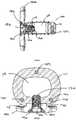
- FIG. 1is a perspective view of an intervertebral implant in accordance with one exemplary embodiment of the invention
- FIG. 2is a top view of the implant of FIG. 1 ;
- FIG. 3is a front view of the implant of FIG. 1 ;
- FIG. 4is a side view of the implant of FIG. 1 ;
- FIG. 5is a rear view of the implant of FIG. 1 ;
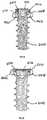
- FIG. 6is a cross section view of the intervertebral implant of FIG. 1 , showing a hole configuration
- FIG. 7is a side view of the implant of FIG. 1 with a first alternative exemplary type of surface
- FIG. 8is a side view of the implant of FIG. 1 with a second alternative exemplary type of surface
- FIG. 9is a micrograph showing distribution of titanium on a PEEK substrate, providing an illustrative exemplary composition of the invention.
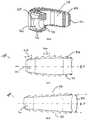
- FIG. 10is a perspective view of an alternative exemplary embodiment view of an insertion instrument
- FIG. 11is an enlarged perspective view of an insertion instrument of FIG. 10 , engagement end;
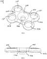
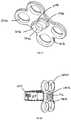
- FIG. 12( a )is a cross section view of the insertion instrument of FIG. 10 , showing the attachment mechanism;
- FIG. 12( b )is an enlarged truncated cross section view of the insertion instrument implant attachment of FIG. 10 ;
- FIG. 13is an enlarged axial view of the insertion instrument of FIG. 10 , showing visualization of the alignment features;
- FIG. 14is a top of view of the insertion instrument of FIG. 10 ;
- FIG. 15is a perspective view of a plate for attachment to an intervertebral implant of FIG. 1 , in accordance with one exemplary embodiment of the invention.
- FIG. 16is a side view of the implant of FIG. 15 ;
- FIG. 17is a perspective view of a plate's posterior side showing rectangular connection of the plate shown in FIG. 15 ;
- FIG. 18is a perspective view of the plate shown in FIG. 15 , attached to intervertebral implant of FIG. 1 , with attachment mechanism;
- FIG. 19is a side cross section view of the plate and intervertebral implant assembly of FIG. 18 , showing connection means;
- FIG. 20is a top cross section view of the plate and intervertebral implant assembly of FIG. 18 , showing connection means;
- FIG. 21is a perspective view of a fully configured plate and intervertebral implant, shown in FIG. 18 , with bone screws, in accordance with another exemplary embodiment of the invention.
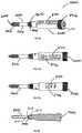
- FIG. 22is a side view of the fully configured plate and intervertebral implant assembly of FIG. 21 ;
- FIG. 23is a perspective view of a fifth exemplary embodiment, showing a bone screw with cantilever segments
- FIG. 24is a truncated cross section view of the bone screw shown in FIG. 23 , inserted into the plate shown in FIG. 15 , in a non-locked state;
- FIG. 25is a truncated cross section view of the bone screw of FIG. 23 , inserted into the plate shown in FIG. 15 , in a locked state;
- FIG. 26is a perspective view of a sixth exemplary embodiment, showing a bone screw with removable body extension
- FIG. 27( a )is a side view of a bone screw with removal body extension shown in FIG. 26 , showing descriptive information;
- FIG. 27( b )is a further rotated side view of a bone screw with removal body extension shown in FIG. 26 , showing descriptive information;
- FIG. 28is a cross section view of bone screw with removal body extension shown in FIG. 26 ;
- FIG. 29is a side view of a removal body extension showing descriptive information
- FIG. 30is a perspective view showing the removable body extension of FIG. 29 , attached to the plate shown in FIG. 15 ;
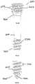
- FIG. 31is a perspective view of a sixth exemplary embodiment, showing a bone screw
- FIG. 32is another perspective view of the bone screw shown in FIG. 31 ;
- FIG. 33is another side view of the showing a bone screw shown in FIG. 31 ;
- FIG. 34is a top view showing the bone screw of FIG. 31 ;
- FIG. 36is an enlarged view of the proximal end of the bone screw shown in FIG. 31 ;
- FIG. 37is an enlarged view of the shaft of the bone screw shown in FIG. 31 ;
- FIG. 38is an enlarged view of the distal end of the bone screw shown in FIG. 31 ;
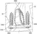
- FIG. 39is a perspective view of an osteotomy implant according to an exemplary embodiment of the present invention.
- FIG. 40is a side elevational view of the osteotomy implant shown in FIG. 39 ;
- FIG. 41is a bottom plan view of the osteotomy implant shown in FIG. 40 , taken along lines 41 - 41 FIG. 40 ;
- FIG. 42is a lateral side elevational view of the osteotomy implant shown in FIG. 40 , taken along lines 42 - 42 of FIG. 40 ;
- FIG. 43is a perspective view of the osteotomy implant shown in FIGS. 39-42 inserted into a bone of a foot.
- FIG. 45is an enlarged top plan view of the osteotomy implant and faceplate shown in FIG. 43 .
- anteriorrefers to features having a relative position toward the front side of a spine
- posteriorrefers to features having a relative position toward the rear side of the spine
- superioriorrefers to features having a relative position above other features, in the cranial direction
- inferiorrefers to features having a relative position below other features in a caudal direction.
- the terminologyincludes the words specifically mentioned, derivatives thereof and words of similar import.
- exemplaryis used herein to mean serving as an example, instance, or illustration. Any aspect or design described herein as “exemplary” is not necessarily to be construed as preferred or advantageous over other aspects or designs. Rather, use of the word exemplary is intended to present concepts in a concrete fashion.
- the term “or”is intended to mean an inclusive “or” rather than an exclusive “or”. That is, unless specified otherwise, or clear from context, “X employs A or B” is intended to mean any of the natural inclusive permutations. That is, if X employs A; X employs B; or X employs both A and B, then “X employs A or B” is satisfied under any of the foregoing instances.
- the articles “a” and “an” as used in this application and the appended claimsshould generally be construed to mean “one or more” unless specified otherwise or clear from context to be directed to a singular form.
- Interbody cages constructed from rigid materials such as titaniumtend to have a large Young's modulus in the range of 105-130 GPa compared to bone, which has a relatively low modulus of 1.8 GPa. This makes titanium at least 58 times stiffer than bone and clinical studies have concluded this as the main cause of subsidence within the vertebral endplates. Subsidence is where the implant breaks through the vertebral endplates and intervertebral spacing is lost. Subsidence has been linked to pseudo-arthrosis, non-unions and re-operations of the fusion site.
- the high material stiffnessmay also enhance stress shielding of the central graft preventing or delaying bone through growth.
- the surface of titaniumis well known for its osteoconductive properties. Osteoconductive materials encourage cell adhesion to the surface and can act like bone itself. This property can be used to increase the fusion area and allow bone growth directly on the implant.
- PEEKThe other well utilized material for intervertebral spacers is PEEK.
- PEEKis a semicrystalline thermoplastic with excellent mechanical and chemical resistance properties that are retained to high temperatures.
- intervertebral spacers constructed from PEEKhave found a growing usage due to their relatively low stiffness, approximately 3.6 GPa compared to 1.8 GPa for bone.
- Clinical literaturehas reported lower occurrences of subsidence with PEEK intervertebral spacers, compared to a titanium spacer.
- PEEKis not an osteoconductive material and as such placement of a PEEK spacer within the intervertebral disc space can reduce the fusion area 60-70%, thus lowering the chances of a full fusion.
- the intervertebral spacers of the present inventionimprove upon prior approaches by addressing the subsidence and settling of the endplates, while maximizing the fusion area.
- the various embodiments of the present inventionallow proper load distribution through the use of low stiffness material enabling the load to transfer through the bone graft material during implant settling, while increasing the fusion area and reducing the mitigation risks.
- the embodimentsinclude an osteoconductive material, such as titanium, applied on a substrate with similar properties to bone.
- the inferior and superior surfacesare configured to maximize the surface area through the use of a rectangular pyramid shaped tooth.
- the assemblyalso includes a mechanism which can engage both an insertion instrument and supplemental hardware, such as a plate and screw assembly.
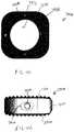
- Interbody spacer 100in accordance with one exemplary embodiment of the invention is shown.
- Interbody assemblies in accordance with the present inventionmay include a variety of body and teeth configurations.
- Interbody spacer 100includes a rigid body 111 and a plurality of peaks, or teeth, 112 which form rigid body 111 .
- Rigid body 111has an anterior surface 113 and a posterior surface 114 that is generally parallel to the anterior surface.
- Anterior surface 113has a larger external surface area than posterior surface 114 .
- Anterior and posterior surfaces 113 , 114are joined by a pair of lateral side surfaces 115 that extend generally radially to one another.
- a superior end surface 116extends generally in a first plane and an inferior end surface 117 extends generally in a second plane obliquely, in a non-parallel manner, to the first plane between anterior side surface 113 and posterior side surface 114 .
- Superior and inferior end surfaces 116 , 117taper or converge toward one another as end surfaces 116 , 117 extend toward posterior side surface 114 , forming a wedge-shaped structure.
- the anterior, posterior and lateral side surfaces, 113 , 114 , and 115surround a generally centrally located cavity 118 that forms a space for fusion material, such as a bone graft or bone graft substitute.
- Interbody spacer 100includes a recess 120 extending through anterior surface 113 inwardly toward cavity 118 and generally centered between the superior 116 and inferior 117 surfaces.
- Recess 120allows for the alignment of a congruent extension 1012 from either an instrument such as an insertion instrument 1000 , shown in FIG. 10 , or an implant assembly such as plate assembly 1500 , shown in FIG. 15 .
- An aperture 119is centrally located within the recess 120 between the anterior surface 113 and the cavity 118 .
- the aperture 119may be configured in either a threaded configuration, interference configuration or any means to secure the interbody spacer 100 to a separate device.
- FIG. 2illustrates a top view of the interbody spacer 100 having a generally oval shape. This shape is generated by rounding the anterior 113 , posterior 114 , and lateral surfaces 115 , as well as the corner surfaces 211 .
- the central opening 118can be constructed by creating a uniform offset of the outer perimeter 213 .
- the interbody spacer 100benefits from a uniform geometry allowing the interbody to more evenly distribute the load distribution on the vertebral endplates.
- the center line A-Pis defined by a line passing from the anterior surface 113 to the posterior surface 114 .
- the L-L lineis defined by a line passing from the lateral surface 115 to the other lateral surface 115 .
- FIG. 3illustrates the interbody spacer 100 from the anterior direction and shows the recess 120 and aperture 119 .
- the recess 120is defined by parallel edge 312 , which forms a line segment and can be used to block rotation of congruent extension 1012 during insertion of the interbody spacer 100 into a patient (not shown).
- the teeth 112are defined by the “V” shaped anterior groove 311 , however this groove can be a “U” shaped groove, “L” shape groove, “O” shape groove or any other configuration of groove which is create by a low peak (or trough) 314 , a high peak 315 , and peak width 316 .
- FIG. 4illustrated a side profile of an interbody spacer 100 , which is shown as having a non-symmetric shape 400 .
- the implant superior surface 116 ′ and inferior surface 117 ′cannot be mirrored about the A-P axis, thus defining the non-symmetric shape.
- the superior surface 117 ′is defined by a superior convex dome 412 in an anterior-posterior direction, which is used to match the inferior vertebral endplate, not shown.
- the teeth 112 viewed from a lateral directionare constructed from an “L” shape groove 413 in the L-L direction. In order to maintain equal distance between peaks 315 on a domed surface, the teeth 112 must repeat at a crest angle ( ⁇ ), where crest angle ⁇ is greater than 0 degrees.
- Exemplary values for crest angle ⁇may be between about 0 degrees and about 90 degrees. In an exemplary embodiment, crest angle ⁇ is about 10 degrees.
- the surfaces of adjacent peaks that define angle ⁇extend generally perpendicular to the domed surface.
- the inferior surface 117 ′ teeth 112are parallel to the A-P line and crest angle ⁇ is approximately 0 degrees between high peaks 315 .
- FIG. 5shows a posterior view of the interbody spacer 400 , which shows the overall wedge shaped.
- the posterior surface 114is a wedge shape to aid in the insertion of the interbody spacer 100 into the vertebral disc space.
- FIG. 6shows the cross-sectional view of the interbody spacer 100 as well as the recess 120 , aperture 119 and a marker bore 612 .
- the recess 120extends sufficiently into the interbody rigid body 111 enough to create a parallel edge 312 .
- the aperture 119extends from the recess 312 into the central opening 118 .
- Marker bore 612generally is a cylindrical in shape, however this can be rectangular, triangular, or other suitable shape. Marker bore 612 is used to insert marker 1251 (shown in FIG. 12 b ), which can be constructed from any radiopaque material, such as stainless steel, titanium, tantalum, etc.
- the markers 1251when viewed from an anterior direction, show the interbody spacer's 100 width, which is defined from lateral surface 115 to opposing surface lateral surface 115 .
- the markers 1251 when viewed from the lateral positionshow the depth of the implant. The depth is defined as the distance between the anterior surface 113 and the posterior surface 114 .
- FIGS. 7 and 8show side views of an alternative embodiment of curved symmetric interbody spacer 700 and straight symmetric interbody spacer 800 , respectively, where the superior surface 116 and inferior surface 117 are symmetric about the A-P line.
- symmetrical interbody spacers 700 and 800may mate with the opposing vertebral endplates better than a non-symmetric interbody spacer 400 .
- the symmetric interbodies 700 and 800are defined when the superior dome 412 or superior surface 116 can be mirrored about the A-P centerline to be equivalent to the inferior dome 711 or inferior surface 117 .
- the width of rear crest 714is generally larger than the width of mid crest 716 , which allows for the interbody spacers 400 , 700 and 800 to wedge itself between the vertebral endplates.
- the rear crest 714can be aided by aligning the superior 116 and inferior 117 surfaces at an angle 812 from the A-P centerline.
- angle 812can be between about 0 degrees and about 90 degrees.
- the angle 812can be used to match the spine curvature, such as Kyphosis or Lordosis angles.
- FIG. 9is a micrograph of a cross sectional cut of a substrate 910 and porous coating 912 on the surface of an interbody spacer 100 , including at least one side of each of the the teeth 112 .
- the thickness of porous coating 912can be between about 25 ⁇ m and about 800 ⁇ m thick.
- the substrate 910can be any polymeric material, such as PEEK, Polymethyl Methacrylate (PMMA), or any other biocompatible polymer with a Young's modulus between about 0.1 GPa and about 50 GPa, which may be used as the interbody spacer 100 .
- the porous coating 912is constructed from an osteoconductive material, such as titanium, nickel titanium, or any other material which may encourage bone in growth.
- the porous coating 912is rigidly bounded to substrate 910 through a bonded layer 911 , such as by a plasma spray, vapor deposition, or another other surface additive method.
- the pores in substrate 912contains small to large size cavities 914 , which encourage bone in-growth and attachment.
- the porosity of the pores substrate 912can be between about 5 percent and about 80 percent porous.
- the interbody spacer 100 superior dome 412 and superior surface 116are coated with the porous coating 912 , as is the inferior dome 711 and inferior surfaces 117 .
- the coatingallows the interbody spacer rigid body 111 to maintain the low stiffness, which can be constructed from PEEK or low stiffness polymer, while gaining the porous coating 912 with osteoconductive properties.
- a hydroxyapatite coatingcan be applied on surfaces 113 , 114 , 115 and on the walls of cavity 118 to enhance for visualization of implant 100 after implementation.
- FIGS. 10-14Another embodiment of the invention is the insertion instrument 1000 illustrated in FIGS. 10-14 , which is used to insert interbody 100 into the spine.
- the insertion instrument 1000must capture the interbody spacer 100 , position the interbody spacer 100 , and deploy the interbody spacer 100 in between two adjacent vertebral bodies (not shown).
- the insertion instrument 1000has a handle 1010 used to grip the instrument and rear end 1020 that can cooperate with an impact device (not shown).
- the hollow shaft 1016is of a smaller diameter than the handle and has enough length to maneuver around soft tissue.
- Located between the shaft 1016 and handle 1010has a cam 1018 used to engage and disengage a drive shaft 1252 from the aperture 119 in the interbody spacer 100 .
- a fastener portion, or engagement end 1014is located at the opposite end from the rear end 1020 .
- the engagement end 1014is illustrated in FIGS. 11-12 b and is designed to releasably engage the interbody spacer 100 .
- the engagement end 1014contains an engagement extension 1112 , which is located at the end of the drive shaft 1252 .
- the engagement extension 1112is centrally located within the congruent extension 1012 , which is defined by two parallel edges 1120 .
- the congruent extension 1012must contain at least one parallel edge 1114 but can be in a circular, rectangular, hexagonal, triangular or oblong.
- the engagement end 1014may also have depth stop 1115 , which is used to control the placement of the interbody spacer 100 within the intervertebral disc space. The height of the depth stops 1115 must be greater than the highest interbody spacer 100 .
- FIGS. 12-14illustrate the attachment of the interbody spacer 100 to the insertion instrument 1000 .
- the interbody spacer 100is positioned at the engagement end 1014 of the insertion instrument 1000 .
- the engagement extension 1112is coaxially aligned with and inserted into the implant aperture 119 in the recess 120 and the cam 1018 is rotated.
- the cam 1018translates rotational motion through the drive shaft 1252 and extends engagement extension 1112 , until engagement is achieved.
- the engagement extension 1112 and aperture 119have matching threads, however engagement may also be completed by an interference fit or other suitable engagement means.
- the rotation of the cam 1018draws the interbody spacer 100 until contact is achieved with depth stops 1115 .
- the interbody spacer 100is then placed into position by using an impaction device (not shown), such as, for example, a mallet, a hammer, a slap hammer, or other such device, on the rear end 1020 until the depth stops 1114 are flush with the surface of the vertebral bodies (not shown).
- the cam 1018is then rotated in the reverse (unlocking) direction to retract engagement extension 1112 inwardly into shaft 1016 in the direction of arrow “A” in FIG. 12 a , and the engagement extension 1112 is then removed from interbody spacer 100 .
- an impaction devicesuch as, for example, a mallet, a hammer, a slap hammer, or other such device
- indicator arrows 613point towards the superior surface 116 and superior dome 412 .
- the surgeonneeds to visualize these indicator arrows 613 and the insertion instrument 1000 depth stop 1115 must have a width 1310 small enough to visualize the arrows 613 .
- the plate assembly 1500contains a rigid body 1508 , which is defined by anterior surface 1510 , posterior surface 1512 , and an external perimeter 1518 .
- the platehas a generally “dog bone” shape but can have a rectangular, square or triangular shape.
- the plate 1500includes at least two screw recesses 1520 .
- Located in the center of the plateis a generally frusto-conical countersunk surface 1542 and attachment aperture 1540 .
- the attachment aperture 1540is designed to align coaxially with the interbody spacer 100 aperture 119 and has an equal or larger diameter than aperture 119 .
- the countersunk surface 1542 and attachment aperture 1540are coaxially aligned with the congruent extension 1012 .
- the attachment aperture 1540is shown with a circular configuration but could be an oblong or oval shape to allow linear translation of a locking screw 1810 (shown in FIG. 18 ) relative to the plate 1500 .
- FIGS. 16-17show a side view and bottom view of a congruent extension 1012 , respectively.
- the congruent extension 1012is located on the posterior side 1512 of the plate assembly 1500 and is designed to engage with a recess 120 , such as the one contained on the interbody spacer 100 .
- the interbody spacer 100is designed to sit in the center of plate assembly 1500 . As such, the interbody 100 may be recessed beneath the vertebral walls. Therefore, the congruent extension 1012 sits on a congruent extension shelf 1720 .
- the mating side of the congruent extension shelf 1720matches the surface of the implant, such as the anterior surface 113 of the interbody spacer 100 .
- the congruent extension 1012contains at least one straight portion 1722 that engages parallel edge 312 , which may be incorporated into a circle, square, rectangle, triangle or oblong shape.
- the congruent extension 1012cooperatively engages the recess 112 of the interbody spacer 100 , as illustrated in FIGS. 18-20 .
- locking screw 1810can be used to secure the plate assembly 1500 to the interbody 100 .
- the locking screw 1810generally has instrument recess 1812 on the head 1912 and threads on the shaft 1910 .
- the instrument recess 1812is shown with a hexagonal connection but those skilled in the art will recognize that the connection can be a Torx, Philips, Square or any other torque transmitting connection.
- the locking screw 1810has sufficient length for the trailing end 1914 to remain slightly recessed or extend in the central opening 118 .
- the shaft 1910is threaded into the aperture 119 in the interbody spacer 100 ; however this can be an interference fit or any other fit in which the locking screw 1810 cannot disengage from the interbody spacer 100 .
- FIGS. 21 and 22illustrate the attachment of bone screw 2100 to the plate assembly 1500 and interbody spacer 100 .
- a first plurality of the recesses 1520extends above the upper surface of implant 100 and a second plurality of recesses 1512 extends below the lower surface of the implant 100 .
- the combination of the bone screws 2100 in the plate assembly 1500 and interbody spacer 100is to prevent motion post-operatively to enable the vertebral bodies to fuse to the porous coating 912 of interbody spacer 100 and achieve bone growth through the central opening 118 .
- the bone screws 2100have a bulbous head 2110 and a head recess 2116 designed for engaging a mechanical translating instrument, such as a screw driver.
- the shaft 2118is composed of a plurality of bone threads 2114 and terminate at a distal end 2112 .
- the distal end 2112is configured to self-drill and tap into the bone with the use of minimal instrumentation.
- the plate assembly 1500 screw recess 1520is designed with a spherical seat 2412 (shown in FIG. 24 ) to allow the bulbous head 2110 to seat in a variety of angular positions based of on an angle 2212 (shown in FIG. 22 ) from the center axis 2214 of the plate assembly 1500 .
- the angle 2212allows for the surgeon to customize the position of the bone screw 2100 intraoperatively.
- the spherical like shape of the bulbous head 2110allows for the bone screws 1500 to adapt as the vertebral endplates settle on the superior surface 116 and inferior surface 117 of the interbody spacer 100 .
- This plate configurationis known as semi-constrained; however the bone screw recess 1520 could be slotted to allow for linear dynamic transition of the bulbous head 2110 .
- the locking head 2300 of bone screw 2100is composed of a plurality of cantilever segments 2310 extending around the head 2300 that are created when a circular groove 2314 is segmented by a plurality of gaps 2312 at equal distance from each other. In order for the cantilever segments 2310 to deform, at least one gap 2312 must be created between them.
- the groove 2314is created circumferentially around the axis 2320 of bone screw 2100 and extends outwards from the head recess 2116 .
- FIGS. 24 and 25show the bone screw 2100 inserted into a rigid plate body 1508 in an unlocked and locked position, respectively.
- the rigid body 1508 screw recess 1520is designed to have a spherical seat 2412 , an undercut ledge 2520 , and a cylindrical section 2522 extending inwardly from the ledge 2520 .
- the spherical seat 2412is designed to cooperatively engage the bone screws bulbous head 2110 while allowing translation about the bone screw bore center axis 2214 .
- the cantilever segments 2310are designed to deflect, or bias, inwardly during insertion of the bone screw 2100 in the screw recess 1520 by contacting the cylindrical section 2522 and deflecting towards the bone screw axis 2320 .
- the deflectionis great enough to allow the bulbous head 2110 to pass, but not enough to plastically deform the cantilever segments 2310 .
- the cantilever segments 2310elastically spring back, or bias outwardly beneath cylindrical section 2522 .
- the undercut ledge 2520prevents the bone screws 2100 from disengaging from the plate 1508 .
- the undercut ledge 2520also blocks excessive rotation of the bulbous head 2110 but contacts the top of the cantilever segment 2310 .
- FIGS. 26-30Another exemplary embodiment of the invention is a removable body extension assembly 2600 as illustrated in FIGS. 26-30 .
- the removable body extension assembly 2600is a cylindrical shaped extension, which can be attached to a headless bone screw 2610 , bone screw 2100 , plate 1500 , or any other implantable implant requiring UDI tracking.
- the removable body extension assembly 2600allows for indicia, or descriptive information 2710 , such as the part number 2714 and or serial/lot number 2716 , to be contained with the implant, specifically, when the surface area, like the shaft 2616 of screw 2610 , is not large enough to contain the descriptive information 2710 .
- the removable body extension assembly 2600has an engagement end 2810 specifically designed to interface with an implant.
- the engagement extension 2810is threaded to engage recess 3212 in the proximal head 2630 of a headless compression bone screw 2610 .
- the engagement extension 2810can be press fit or have an interference fit engagement recess 3212 or head recess 3210 of the implant.
- the engagement extension 2810may also be manufactured directly as part of the implant in a monolithic configuration and disengage through breaking connection located at the engagement extension end 2810 .
- the removable body extension 2600Prior to inserting headless compression screw 2610 , the removable body extension 2900 is used to remove the screw from a screw caddie (not shown). The removable body extension 2900 is then removed by unscrewing the engagement section 2810 from the engagement recess 3212 of screw 2610 . Screw 2610 is then inserted into the patient. The removable body extension 2900 is left outside of the patient and the descriptive information 2710 is recorded.
- FIG. 30shows an example of a plate 1500 with the removable body extension 2900 attached via the engagement extension 2810 .
- the removable body extension 2900can be attached to a number of implants, such as the interbody spacer 100 , plate 1500 , headless compression screw 2610 , bone staple (not shown), suture anchor (not shown), or any other implant which is too small to physically laser mark descriptive information 2710 .
- headless compression screw 2610is shown in more detail.
- the headless compression screw 2610is defined by proximal head 2630 and a distal end 2640 joined by a shaft 2616 .
- the distal end 2640has distal threads 2612 with a distal pitch 3310 and the proximal head 2630 has proximal threads 2614 with a proximal thread pitch 3312 , where the proximal thread pitch 3312 is less than distal thread pitch 3310 .
- the difference in proximal thread pitch 3312 and distal thread pitch 3310causes a compressive force to generate between segments.
- the proximal head 2630has an engagement recess 3210 which can be a Torx, Hexagonal, Square, or Phillips in shape.
- FIGS. 36-38specifically show the self-cutting features of the headless bone screw 2620 .
- the proximal head 2630has a groove 3620 , which removes material as the proximal head 2630 and the proximal threads 2614 begin to engage a substrate, such as bone.
- FIG. 37illustrates a reverse cutting groove 3720 positioned on the distal end 2640 and engages the distal threads 2612 near the shaft 2616 .
- the reverse cutting groove 3720removes material, such as bone, as the headless bone screw 2610 is removed.
- FIG. 38illustrates the tip of the distal end 2640 , which includes distal threads 2612 and self drilling groove 3820 .
- the length of self-drilling groove 3820is greater than the distal thread pitch 3310 and is used as the headless bone screw 2610 is inserted into a substrate such as bone.
- an osteotomy wedge systemaccording to the present invention is disclosed.
- the wedge systemcan be used for internal fixation of bone fractures, fusions, or osteotomies in lower limbs, such as, for example, tibial osteotomies, Evans osteotomies, metatarsal/cuneiform arthrodesis, Cotton osteotomies, as well as other indications.
- the inventive wedge systemprovides a fusion site for bone to grow into an osteotomy wedge to secure the wedge into an incision that is formed in the bone into which the wedge is inserted.
- the wedgehelps to stabilize the bone and to properly orient the bone.
- the fusion sitesecures the wedge to the bone as the bone continues to grow.
- the wedge systemincludes a wedge 3900 having a body 3910 that is generally bisected by a central plane 3912 .
- a top plan view of body 3910shown in FIG. 41 , shows that body 3910 is generally parallelogram in shape with rounded corners and has a generally circular opening 3913 extending all of the way therethrough. Circular opening 3913 provides for bone through growth to occur.
- Body 3910is generally wedge-shaped with a thinner central portion 3914 sized to be inserted toward an interior portion of a cut bone 50 , and a wider peripheral portion 3916 , forming a trailing face that is sized to extend toward an exterior of the cut bone 50 .
- Body 3910includes a first surface 3920 , an opposing second surface 3930 , and a core 3950 disposed between first surface 3920 and a second surface 3930 .
- a first surface 3920extends between medial portion 3914 and lateral portion 3916 generally in a first plane 3924 that extends obliquely at an acute angle ⁇ relative to central plane 3912 .
- First surface 3920has a first plurality of longitudinal grooves 3926 and a second plurality of transverse grooves 3928 extending therealong. Portions of first surface 3920 extend between adjacent longitudinal grooves 3926 and transverse grooves 3928 form individual peaks 3929 , similar to the surface of interbody spacer 100 , shown in FIGS. 1-3 .
- a second surface 3930extends between medial portion 3914 and lateral portion 3916 generally in a second plane 3934 on an opposite side of central plane 3912 from first surface 3920 , also at an acute angle ⁇ relative to central plane 3912 .
- Second surface 3930has a first plurality of longitudinal grooves 3936 and a second plurality of transverse grooves 3938 extending therealong. Portions of second surface 3930 extend between adjacent longitudinal grooves 3936 and transverse grooves 3938 form individual peaks 3939 .
- first surface 3920 and second surface 3930includes a osteoconductive coating, such as, for example, a titanium plasma spray coating, that has a thickness of between about 2 microns and about 500 microns.
- the osteoconductive coatingcan be used to add peripheral visualization within minimal imaging artifact.
- the spray coatingis sufficiently thin, such that first surface 3920 and second surface 3930 do not interfere with imaging methods, and are therefore largely transparent to imagery.
- the spray coatingcan be sufficiently thick to enable peripheral visibility of first surface 3920 and second surface 3930 without affecting the visibility of core 3950 via imaging, in order to allow the progress of bone growth to be viewed.
- First surface 3920 and second surface 3930can each be a highly roughened exterior surface to provide an environment conducive to early stability and to ensure intimate osseointegration between bone 50 (shown in FIGS. 43 and 44 ) and implant 3900 .
- the roughened surfacehas an Ra greater than 0.006 microns.
- core 3950can be constructed from a radiolucent material, such as, for example, PEEK, and is transparent on MRI, CT, and x-ray imaging.
- Core 3950has the same Young's modulus as bone, namely, about 3.6 GigaPascals (GPa), which prevent shielding in bone 50 , while also maintaining superior mechanical properties.
- core 3950 having a Young's modulus between about 0.5 GPa and about 18 GPacan be used.
- FIG. 9shows a PEEK core with an osteoconductive (titanium plasma spray) surface
- lateral portion 3916includes an aperture 3940 that is centrally located within a recess 3942 between first surface 3920 and second surface 3930 .
- Aperture 3940can be configured in either a threaded configuration, interference configuration or any means to secure the body 3910 to a separate insertion instrument 1000 (shown in FIG. 14 ).
- aperture 3940has blind threads.
- recess 3942is generally oblong in shape to prevent rotation of implant 3900 respect to insertion instrument 1000 implantation of implant 3900 into bone 50 .
- the inventive osteotomy wedge systemfurther includes a fixation plate 3960 that is attached to bone 50 over wedge 3900 after wedge 3900 is inserted into bone 50 .
- Plate 3960has a first hole 3962 and a second hole 3964 formed therein. A length between first hole 3962 and second hole 3964 is greater than a length between first surface 3920 and the second surface 3930 such that wedge 3900 is located between first hole 3962 and second hole 3964 so that bone fixation screws 3966 can be inserted through first hole 3962 and second hole 3964 , and into bone 50 to secure plate 3962 bone 50 on either side of wedge 3900 .
- plate 3960can include a third hole 3968 disposed between first whole 3962 and second hole 3964 , such that, when plate 3960 is affixed to bone 50 over wedge 3900 , third hole 3968 is aligned with aperture 3940 .
- a fixation screw 3970is insertable through third hole 3968 and into aperture 3940 such that fixation screw 3970 secures fixation plate 3960 to wedge 3900 .
- a cutis made in bone 50 at an osteotomy site.
- the cutis only a partial cut, such that a portion of bone 50 on either side of the cut remains connected.
- a forked wedge tool(not shown) is inserted into the cut and is used to open the osteotomy site.
- wedge 3900is inserted into the cut.
- insertion instrument 1000is removed from wedge 3900 , leaving wedge 3900 in the osteotomy site.
- Fixation plate 3960is applied over wedge 3900 and secured to bone 50 on either side of wedge 3900 by fixation screws 3966 .
- fixation screw 3970can be inserted through third hole 3968 , and into aperture 3940 , securing fixation plate 3960 directly to wedge 3900 .
- each device described above that is to be implantedi.e., interbody, wedge, screws, plate, etc.
- an antimicrobial agentsuch as, for example, silver oxide.
- the anti-microbial coatingcan be in the form of a nano coating or other type of coating. Such an antimicrobial coating can be used to reduce or eliminate infections within the patient.
Landscapes
- Health & Medical Sciences (AREA)
- Orthopedic Medicine & Surgery (AREA)
- Life Sciences & Earth Sciences (AREA)
- Biomedical Technology (AREA)
- Engineering & Computer Science (AREA)
- General Health & Medical Sciences (AREA)
- Animal Behavior & Ethology (AREA)
- Public Health (AREA)
- Veterinary Medicine (AREA)
- Neurology (AREA)
- Heart & Thoracic Surgery (AREA)
- Surgery (AREA)
- Transplantation (AREA)
- Oral & Maxillofacial Surgery (AREA)
- Cardiology (AREA)
- Vascular Medicine (AREA)
- Medical Informatics (AREA)
- Molecular Biology (AREA)
- Nuclear Medicine, Radiotherapy & Molecular Imaging (AREA)
- Chemical & Material Sciences (AREA)
- Physical Education & Sports Medicine (AREA)
- Inorganic Chemistry (AREA)
- Epidemiology (AREA)
- Medicinal Chemistry (AREA)
- Dermatology (AREA)
- Pathology (AREA)
- Prostheses (AREA)
Abstract
Description
Claims (23)
Priority Applications (17)
| Application Number | Priority Date | Filing Date | Title |
|---|---|---|---|
| PCT/US2014/060338WO2015057604A1 (en) | 2012-10-19 | 2014-10-14 | Wedge osteotomy device and method of use |
| US14/513,300US10864081B2 (en) | 2012-10-19 | 2014-10-14 | Wedge osteotomy device and method of use |
| US14/948,322US10201433B2 (en) | 2012-10-19 | 2015-11-22 | System and method for correcting scoliosis |
| US15/162,657US10369251B2 (en) | 2012-10-19 | 2016-05-24 | Anti-microbial and osteointegration nanotextured surfaces |
| US15/213,935US10058431B2 (en) | 2012-10-19 | 2016-07-19 | Small joint fixation |
| US15/646,497US10383737B2 (en) | 2012-10-19 | 2017-07-11 | Anatomical wedge implant |
| US16/049,854US10639163B2 (en) | 2012-10-19 | 2018-07-31 | Small joint fixation |
| US16/201,144US10888365B2 (en) | 2012-10-19 | 2018-11-27 | Lapidus screw guide assembly and method of insertion |
| US16/503,738US11413371B2 (en) | 2013-10-15 | 2019-07-05 | System and method for correcting scoliosis |
| US16/504,405US11547569B2 (en) | 2012-10-19 | 2019-07-08 | Anatomical wedge implant |
| US16/506,144US11285241B2 (en) | 2012-10-19 | 2019-07-09 | Anti-microbial and osteointegration nanotextured surfaces |
| US16/527,185US11147680B2 (en) | 2012-10-19 | 2019-07-31 | Small joint fixation |
| US17/108,168US11389221B2 (en) | 2012-10-19 | 2020-12-01 | Lapidus screw guide assembly and method of insertion |
| US17/495,895US11744709B2 (en) | 2012-10-19 | 2021-10-07 | Small joint fixation |
| US17/829,429US12144531B2 (en) | 2012-10-19 | 2022-06-01 | Lapidus screw guide assembly and method of insertion |
| US18/229,883US20230380982A1 (en) | 2012-10-19 | 2023-08-03 | Small Joint Fixation |
| US18/935,917US20250057575A1 (en) | 2012-10-19 | 2024-11-04 | Beveled Screw |
Applications Claiming Priority (3)
| Application Number | Priority Date | Filing Date | Title |
|---|---|---|---|
| US201261715891P | 2012-10-19 | 2012-10-19 | |
| US14/054,100US9387087B2 (en) | 2012-10-19 | 2013-10-15 | Orthopedic systems for spine and tracking control |
| US14/513,300US10864081B2 (en) | 2012-10-19 | 2014-10-14 | Wedge osteotomy device and method of use |
Related Parent Applications (1)
| Application Number | Title | Priority Date | Filing Date |
|---|---|---|---|
| US14/054,100Continuation-In-PartUS9387087B2 (en) | 2012-10-19 | 2013-10-15 | Orthopedic systems for spine and tracking control |
Related Child Applications (2)
| Application Number | Title | Priority Date | Filing Date |
|---|---|---|---|
| US14/948,322Continuation-In-PartUS10201433B2 (en) | 2012-10-19 | 2015-11-22 | System and method for correcting scoliosis |
| US15/162,657Continuation-In-PartUS10369251B2 (en) | 2012-10-19 | 2016-05-24 | Anti-microbial and osteointegration nanotextured surfaces |
Publications (2)
| Publication Number | Publication Date |
|---|---|
| US20150032220A1 US20150032220A1 (en) | 2015-01-29 |
| US10864081B2true US10864081B2 (en) | 2020-12-15 |
Family
ID=52828807
Family Applications (2)
| Application Number | Title | Priority Date | Filing Date |
|---|---|---|---|
| US14/513,300Active2035-02-23US10864081B2 (en) | 2012-10-19 | 2014-10-14 | Wedge osteotomy device and method of use |
| US16/506,144Active2034-12-07US11285241B2 (en) | 2012-10-19 | 2019-07-09 | Anti-microbial and osteointegration nanotextured surfaces |
Family Applications After (1)
| Application Number | Title | Priority Date | Filing Date |
|---|---|---|---|
| US16/506,144Active2034-12-07US11285241B2 (en) | 2012-10-19 | 2019-07-09 | Anti-microbial and osteointegration nanotextured surfaces |
Country Status (2)
| Country | Link |
|---|---|
| US (2) | US10864081B2 (en) |
| WO (1) | WO2015057604A1 (en) |
Cited By (7)
| Publication number | Priority date | Publication date | Assignee | Title |
|---|---|---|---|---|
| US20200282105A1 (en)* | 2013-03-15 | 2020-09-10 | Beacon Biomedical, Llc | Spinal implants with bioactive glass markers |
| US11723778B1 (en) | 2021-09-23 | 2023-08-15 | Nofusco Corporation | Vertebral implant system and methods of use |
| US11806247B2 (en) | 2020-06-15 | 2023-11-07 | Nofusco Corporation | Intravertebral implant system and methods of use |
| US11883300B2 (en) | 2020-06-15 | 2024-01-30 | Nofusco Corporation | Orthopedic implant system and methods of use |
| USD1017035S1 (en) | 2022-03-31 | 2024-03-05 | Medartis Ag | Osteotomy wedge |
| USD1017034S1 (en) | 2022-03-31 | 2024-03-05 | Medartis Ag | Osteotomy wedge |
| US12144742B2 (en) | 2020-06-15 | 2024-11-19 | Foundation Surgical Group, Inc. | Implant system and methods of use |
Families Citing this family (25)
| Publication number | Priority date | Publication date | Assignee | Title |
|---|---|---|---|---|
| US8425569B2 (en)* | 2010-05-19 | 2013-04-23 | Transcorp, Inc. | Implantable vertebral frame systems and related methods for spinal repair |
| US9579214B1 (en)* | 2011-03-01 | 2017-02-28 | John W. McClellan | Peripheral vertebral body spacer implant and insertion tool |
| US10076364B2 (en) | 2012-06-29 | 2018-09-18 | K2M, Inc. | Minimal-profile anterior cervical plate and cage apparatus and method of using same |
| US9456856B2 (en)* | 2013-09-26 | 2016-10-04 | Warsaw Orthopedic, Inc. | Intrabody osteotomy implant and methods of use |
| US9283091B2 (en)* | 2013-10-07 | 2016-03-15 | Warsaw Orthopedic, Inc. | Spinal implant system and method |
| US9603718B2 (en)* | 2014-02-27 | 2017-03-28 | Alphatec Spine, Inc. | Spacer with temporary fixation plate |
| AU2016200195B2 (en) | 2015-01-14 | 2020-07-02 | Vb Spine Us Opco Llc | Spinal implant with fluid delivery capabilities |
| AU2016200179B2 (en) | 2015-01-14 | 2020-09-17 | Stryker European Operations Holdings Llc | Spinal implant with porous and solid surfaces |
| US20160235455A1 (en)* | 2015-02-14 | 2016-08-18 | Nuvista, Llc | Expandable open wedge implant |
| CA2930123A1 (en) | 2015-05-18 | 2016-11-18 | Stryker European Holdings I, Llc | Partially resorbable implants and methods |
| US10610375B2 (en)* | 2015-08-19 | 2020-04-07 | Raymond J. Quinlan | Spinal fusion device and method of using same |
| WO2017192632A1 (en) | 2016-05-03 | 2017-11-09 | Additive Orthopaedics, LLC | Bone fixation device and method of use |
| WO2017210695A1 (en)* | 2016-06-03 | 2017-12-07 | Additive Orthopaedics, LLC | Bone fixation devices |
| CN105963007A (en)* | 2016-07-08 | 2016-09-28 | 湖南百佳生物工程有限公司 | Minimally invasive pedicle screw system |
| US11058468B2 (en) | 2016-07-29 | 2021-07-13 | Additive Orthopaedics, LLC | Bone fixation device and method of use |
| US10543028B2 (en) | 2017-02-06 | 2020-01-28 | Biomet Manufacturing, Llc | Adjustable wedge |
| US10675157B2 (en)* | 2017-04-05 | 2020-06-09 | Life Spine, Inc. | Lumbar stand-alone spine implant |
| US10624760B2 (en) | 2017-05-22 | 2020-04-21 | Warsaw Orthopedic, Inc. | Spinal implant system and method |
| EP3459502B1 (en) | 2017-09-20 | 2024-05-22 | Stryker European Operations Holdings LLC | Spinal implants |
| US11147679B2 (en) | 2018-02-05 | 2021-10-19 | Paragon Advanced Technologies, Inc. | Bone fixation device |
| US11744619B2 (en) | 2018-04-06 | 2023-09-05 | K2M, Inc. | Faceted bone plate |
| WO2020176514A1 (en)* | 2019-02-25 | 2020-09-03 | University Of Cincinnati | Method and device for endoscopic endonasal occipitocervical fusion |
| CN110200728A (en)* | 2019-07-01 | 2019-09-06 | 中国人民解放军第四军医大学 | A kind of Vertebral defect method for reconstructing of individuation in conjunction with generalization |
| US20240065857A1 (en)* | 2022-08-31 | 2024-02-29 | Apex Orthopedics, LLC | Orthopedic Arthrodesis Dowel Placement Guide, Systems, and Methods for Treating Mid-Foot Disorders |
| FR3151969B1 (en)* | 2023-08-10 | 2025-07-25 | Sc Medica | System for performing spinal arthrodesis via the posterior approach at the level of a facet joint |
Citations (48)
| Publication number | Priority date | Publication date | Assignee | Title |
|---|---|---|---|---|
| US4759351A (en)* | 1986-12-29 | 1988-07-26 | Slocum D Barclay | Osteotomy method for biomechanical femoral neck lengthening and torsion |
| US5152791A (en) | 1989-12-07 | 1992-10-06 | Olympus Optical Co., Ltd. | Prosthetic artificial bone having ceramic layers of different porosity |
| US5766251A (en)* | 1992-03-13 | 1998-06-16 | Tomihisa Koshino | Wedge-shaped spacer for correction of deformed extremities |
| US5888227A (en) | 1995-10-20 | 1999-03-30 | Synthes (U.S.A.) | Inter-vertebral implant |
| US6008433A (en)* | 1998-04-23 | 1999-12-28 | Stone; Kevin R. | Osteotomy wedge device, kit and methods for realignment of a varus angulated knee |
| US6096080A (en)* | 1998-05-06 | 2000-08-01 | Cortek, Inc. | Apparatus for spinal fusion using implanted devices |
| US6261291B1 (en) | 1999-07-08 | 2001-07-17 | David J. Talaber | Orthopedic implant assembly |
| US6306170B2 (en) | 1997-04-25 | 2001-10-23 | Tegementa, L.L.C. | Threaded fusion cage anchoring device and method |
| US20010049560A1 (en)* | 1998-01-30 | 2001-12-06 | Paul David C. | Intervertebral allograft spacer |
| US6432106B1 (en)* | 1999-11-24 | 2002-08-13 | Depuy Acromed, Inc. | Anterior lumbar interbody fusion cage with locking plate |
| US20030125739A1 (en)* | 2001-12-12 | 2003-07-03 | Bagga Charanpreet S. | Bioactive spinal implants and method of manufacture thereof |
| US20040082998A1 (en)* | 2001-02-23 | 2004-04-29 | Kenichi Shinomiya | Artificial pyramid |
| US6790233B2 (en) | 2001-05-01 | 2004-09-14 | Amedica Corporation | Radiolucent spinal fusion cage |
| US20040243241A1 (en) | 2003-05-30 | 2004-12-02 | Naim Istephanous | Implants based on engineered metal matrix composite materials having enhanced imaging and wear resistance |
| US20050010215A1 (en) | 2001-10-18 | 2005-01-13 | Joel Delecrin | Plate for osteosynthesis device and preassembling method |
| US20050075641A1 (en)* | 2003-10-03 | 2005-04-07 | Linvatec Corporation | Osteotomy system |
| US20050101960A1 (en) | 2001-04-03 | 2005-05-12 | Vincent Fiere | Stabilised interbody fusion system for vertebrae |
| US20060036322A1 (en)* | 2004-08-09 | 2006-02-16 | Reiley Mark A | Systems and methods for the fixation or fusion of bone |
| US20060116766A1 (en) | 2004-12-01 | 2006-06-01 | Jean-Philippe Lemaire | Anterior lumbar interbody implant |
| WO2007098288A2 (en) | 2006-02-27 | 2007-08-30 | Synthes (U.S.A.) | Intervertebral implant with fixation geometry |
| US20070270844A1 (en) | 2004-11-03 | 2007-11-22 | The Regents Of The University Of Michigan | Biodegradable implant for intertransverse process fusion |
| US20080021557A1 (en)* | 2006-07-24 | 2008-01-24 | Warsaw Orthopedic, Inc. | Spinal motion-preserving implants |
| US20080230421A1 (en) | 2007-02-28 | 2008-09-25 | Aesculap Ag & Co. Kg | Surgical data carrier |
| US20080243135A1 (en) | 2007-03-30 | 2008-10-02 | Robinson Randolph C | Driver-Fixator System, Method, and Apparatus |
| US20080300634A1 (en)* | 2007-05-31 | 2008-12-04 | Wayne Gray | Spinal interbody system and method |
| US20090036926A1 (en) | 2007-07-31 | 2009-02-05 | Zimmer Spine, Inc. | Method for stabilizing a facet joint |
| US20090048675A1 (en)* | 2007-04-25 | 2009-02-19 | Bhatnagar Mohit K | Spinal Fusion Implants with Selectively Applied Bone Growth Promoting Agent |
| US20090182430A1 (en) | 2008-01-16 | 2009-07-16 | Aesculap Implant Systems, Inc. | Dynamic interbody |
| US7641690B2 (en) | 2004-08-23 | 2010-01-05 | Abdou M Samy | Bone fixation and fusion device |
| US20100152853A1 (en) | 2008-12-17 | 2010-06-17 | X-Spine Systems, Inc. | Prosthetic implant with biplanar angulation and compound angles |
| US20100290091A1 (en) | 2009-05-18 | 2010-11-18 | Xerox Corporation | Method of compensating for clipping in input scanners |
| US20110082551A1 (en)* | 2007-11-27 | 2011-04-07 | Kilian Kraus | Intervertebral implant |
| US20110106171A1 (en) | 2009-11-04 | 2011-05-05 | X-Spine Systems, Inc. | Screw implant and system and method for locking a screw in an implant plate |
| US20110172780A1 (en)* | 2009-12-31 | 2011-07-14 | John Scheland | Method and apparatus for fusing the bones of a joint |
| US20110224734A1 (en) | 2009-10-28 | 2011-09-15 | Orthopro Llc | Compression plate kit and methods for repairing bone discontinuities |
| US20120130496A1 (en)* | 2008-09-02 | 2012-05-24 | Duffield William E | Intervertebral Fusion Implant |
| US8506636B2 (en) | 2006-09-08 | 2013-08-13 | Theken Spine, Llc | Offset radius lordosis |
| US20130211522A1 (en)* | 2011-08-16 | 2013-08-15 | Arnold-Peter C. Weiss | Wedge shaped fracture fixation devices and methods for using the same |
| US20130238095A1 (en) | 2012-03-06 | 2013-09-12 | Nicholas Pavento | Nubbed Plate |
| US20130268080A1 (en) | 2010-08-11 | 2013-10-10 | Warsaw Orthopedic, Inc. | Interbody spinal implants with extravertebral support plates |
| US8556972B2 (en) | 2009-04-02 | 2013-10-15 | Sevika Holding AG | Monolithic orthopedic implant with an articular finished surface |
| US20140031935A1 (en) | 2010-01-13 | 2014-01-30 | Jcbd, Llc | Systems for and methods of fusing a sacroiliac joint |
| US20140128980A1 (en)* | 2010-07-20 | 2014-05-08 | X-Spine Systems, Inc. | Composite orthopedic implant having a low friction material substrate with primary frictional features and secondary frictional features |
| US20150018956A1 (en)* | 2012-06-21 | 2015-01-15 | Renovis Surgical, Inc. | Surgical implant devices incorporating porous surfaces |
| US20150088256A1 (en)* | 2013-09-26 | 2015-03-26 | Warsaw Orthopedic, Inc. | Intrabody Osteotomy Implant and Methods of Use |
| US20150305752A1 (en)* | 2014-04-25 | 2015-10-29 | Biomet Manufacturing, Llc | HTO Guide With Optional Guided ACL/PCL Tunnels |
| US20160151167A1 (en) | 2014-12-01 | 2016-06-02 | Dae Jean JO | Intervertebral cage for spinal implant |
| US20160310286A1 (en) | 2015-04-23 | 2016-10-27 | Disc Fix, L.L.C. | Systems and methods for treatment of intervertebral disc derangements |
Family Cites Families (18)
| Publication number | Priority date | Publication date | Assignee | Title |
|---|---|---|---|---|
| US4542539A (en)* | 1982-03-12 | 1985-09-24 | Artech Corp. | Surgical implant having a graded porous coating |
| DE4208247C1 (en)* | 1992-03-14 | 1993-10-14 | Eska Medical Gmbh & Co | Bone replacement implant |
| US7494507B2 (en)* | 2000-01-30 | 2009-02-24 | Diamicron, Inc. | Articulating diamond-surfaced spinal implants |
| US5489306A (en)* | 1995-01-03 | 1996-02-06 | Gorski; Jerrold M. | Graduated porosity implant for fibro-osseous integration |
| US5620448A (en)* | 1995-03-24 | 1997-04-15 | Arthrex, Inc. | Bone plate system for opening wedge proximal tibial osteotomy |
| US7067169B2 (en)* | 2003-06-04 | 2006-06-27 | Chemat Technology Inc. | Coated implants and methods of coating |
| WO2006060482A2 (en) | 2004-12-01 | 2006-06-08 | The Regents Of The University Of California | Systems, devices and methods of treatment of intervertebral disorders |
| US20060129215A1 (en)* | 2004-12-09 | 2006-06-15 | Helmus Michael N | Medical devices having nanostructured regions for controlled tissue biocompatibility and drug delivery |
| US7655162B2 (en) | 2005-03-03 | 2010-02-02 | Biomet Manufacturing Corp. | Acetabular shell system and method for making |
| WO2007130648A2 (en)* | 2006-05-05 | 2007-11-15 | Ceramatec, Inc. | Fully or partially bioresorbable orthopedic implant |
| US20080097620A1 (en)* | 2006-05-26 | 2008-04-24 | Nanyang Technological University | Implantable article, method of forming same and method for reducing thrombogenicity |
| US20080027431A1 (en) | 2006-07-29 | 2008-01-31 | Williams James M | Coated medical device and method of making |
| US20090035722A1 (en)* | 2007-08-01 | 2009-02-05 | Ganesan Balasundaram | Hydroxyapatite coated nanostructured titanium surfaces |
| US8753561B2 (en)* | 2008-06-20 | 2014-06-17 | Baxter International Inc. | Methods for processing substrates comprising metallic nanoparticles |
| US20100183501A1 (en)* | 2009-01-16 | 2010-07-22 | Medtronic Vascular, Inc. | Medical Devices With Nanotextured Titanium Coating |
| US20100255447A1 (en)* | 2009-04-07 | 2010-10-07 | University Of Arkansas | Advanced bio-compatible polymer surface coatings for implants and tissue engineering scaffolds |
| US8647675B2 (en) | 2012-03-08 | 2014-02-11 | Pacesetter, Inc. | Silver nanoparticle antimicrobial coating for long-term and short-term infection resistance |
| KR20150005986A (en) | 2012-05-09 | 2015-01-15 | 아메디카 코포레이션 | Methods for altering the surface chemistry of biomedical implants and related apparatus |
- 2014
- 2014-10-14USUS14/513,300patent/US10864081B2/enactiveActive
- 2014-10-14WOPCT/US2014/060338patent/WO2015057604A1/enactiveApplication Filing
- 2019
- 2019-07-09USUS16/506,144patent/US11285241B2/enactiveActive
Patent Citations (53)
| Publication number | Priority date | Publication date | Assignee | Title |
|---|---|---|---|---|
| US4759351A (en)* | 1986-12-29 | 1988-07-26 | Slocum D Barclay | Osteotomy method for biomechanical femoral neck lengthening and torsion |
| US5152791A (en) | 1989-12-07 | 1992-10-06 | Olympus Optical Co., Ltd. | Prosthetic artificial bone having ceramic layers of different porosity |
| US5766251A (en)* | 1992-03-13 | 1998-06-16 | Tomihisa Koshino | Wedge-shaped spacer for correction of deformed extremities |
| US5888227A (en) | 1995-10-20 | 1999-03-30 | Synthes (U.S.A.) | Inter-vertebral implant |
| US6306170B2 (en) | 1997-04-25 | 2001-10-23 | Tegementa, L.L.C. | Threaded fusion cage anchoring device and method |
| US20010049560A1 (en)* | 1998-01-30 | 2001-12-06 | Paul David C. | Intervertebral allograft spacer |
| US6008433A (en)* | 1998-04-23 | 1999-12-28 | Stone; Kevin R. | Osteotomy wedge device, kit and methods for realignment of a varus angulated knee |
| US6096080A (en)* | 1998-05-06 | 2000-08-01 | Cortek, Inc. | Apparatus for spinal fusion using implanted devices |
| US6261291B1 (en) | 1999-07-08 | 2001-07-17 | David J. Talaber | Orthopedic implant assembly |
| US6432106B1 (en)* | 1999-11-24 | 2002-08-13 | Depuy Acromed, Inc. | Anterior lumbar interbody fusion cage with locking plate |
| US20040082998A1 (en)* | 2001-02-23 | 2004-04-29 | Kenichi Shinomiya | Artificial pyramid |
| US20050101960A1 (en) | 2001-04-03 | 2005-05-12 | Vincent Fiere | Stabilised interbody fusion system for vertebrae |
| US6790233B2 (en) | 2001-05-01 | 2004-09-14 | Amedica Corporation | Radiolucent spinal fusion cage |
| US20050010215A1 (en) | 2001-10-18 | 2005-01-13 | Joel Delecrin | Plate for osteosynthesis device and preassembling method |
| US20030125739A1 (en)* | 2001-12-12 | 2003-07-03 | Bagga Charanpreet S. | Bioactive spinal implants and method of manufacture thereof |
| US7238203B2 (en) | 2001-12-12 | 2007-07-03 | Vita Special Purpose Corporation | Bioactive spinal implants and method of manufacture thereof |
| US20040243241A1 (en) | 2003-05-30 | 2004-12-02 | Naim Istephanous | Implants based on engineered metal matrix composite materials having enhanced imaging and wear resistance |
| US20050075641A1 (en)* | 2003-10-03 | 2005-04-07 | Linvatec Corporation | Osteotomy system |
| US20060036322A1 (en)* | 2004-08-09 | 2006-02-16 | Reiley Mark A | Systems and methods for the fixation or fusion of bone |
| US20110184478A1 (en)* | 2004-08-09 | 2011-07-28 | Si-Bone, Inc. | Systems and methods for the fixation or fusion of bone |
| US7641690B2 (en) | 2004-08-23 | 2010-01-05 | Abdou M Samy | Bone fixation and fusion device |
| US20070270844A1 (en) | 2004-11-03 | 2007-11-22 | The Regents Of The University Of Michigan | Biodegradable implant for intertransverse process fusion |
| US20060116766A1 (en) | 2004-12-01 | 2006-06-01 | Jean-Philippe Lemaire | Anterior lumbar interbody implant |
| WO2007098288A2 (en) | 2006-02-27 | 2007-08-30 | Synthes (U.S.A.) | Intervertebral implant with fixation geometry |
| US20080021557A1 (en)* | 2006-07-24 | 2008-01-24 | Warsaw Orthopedic, Inc. | Spinal motion-preserving implants |
| US8506636B2 (en) | 2006-09-08 | 2013-08-13 | Theken Spine, Llc | Offset radius lordosis |
| US20080230421A1 (en) | 2007-02-28 | 2008-09-25 | Aesculap Ag & Co. Kg | Surgical data carrier |
| US20080243135A1 (en) | 2007-03-30 | 2008-10-02 | Robinson Randolph C | Driver-Fixator System, Method, and Apparatus |
| US20090048675A1 (en)* | 2007-04-25 | 2009-02-19 | Bhatnagar Mohit K | Spinal Fusion Implants with Selectively Applied Bone Growth Promoting Agent |
| US20080300634A1 (en)* | 2007-05-31 | 2008-12-04 | Wayne Gray | Spinal interbody system and method |
| US8216312B2 (en)* | 2007-05-31 | 2012-07-10 | Zimmer Spine, Inc. | Spinal interbody system and method |
| US20090036926A1 (en) | 2007-07-31 | 2009-02-05 | Zimmer Spine, Inc. | Method for stabilizing a facet joint |
| US20110082551A1 (en)* | 2007-11-27 | 2011-04-07 | Kilian Kraus | Intervertebral implant |
| US20090182430A1 (en) | 2008-01-16 | 2009-07-16 | Aesculap Implant Systems, Inc. | Dynamic interbody |
| US9358127B2 (en)* | 2008-09-02 | 2016-06-07 | Globus Medical, Inc. | Intervertebral fusion implant |
| US20120130496A1 (en)* | 2008-09-02 | 2012-05-24 | Duffield William E | Intervertebral Fusion Implant |
| US20100152853A1 (en) | 2008-12-17 | 2010-06-17 | X-Spine Systems, Inc. | Prosthetic implant with biplanar angulation and compound angles |
| US8556972B2 (en) | 2009-04-02 | 2013-10-15 | Sevika Holding AG | Monolithic orthopedic implant with an articular finished surface |
| US20100290091A1 (en) | 2009-05-18 | 2010-11-18 | Xerox Corporation | Method of compensating for clipping in input scanners |
| US20110224734A1 (en) | 2009-10-28 | 2011-09-15 | Orthopro Llc | Compression plate kit and methods for repairing bone discontinuities |
| US20110106171A1 (en) | 2009-11-04 | 2011-05-05 | X-Spine Systems, Inc. | Screw implant and system and method for locking a screw in an implant plate |
| US20110172780A1 (en)* | 2009-12-31 | 2011-07-14 | John Scheland | Method and apparatus for fusing the bones of a joint |
| US20140031935A1 (en) | 2010-01-13 | 2014-01-30 | Jcbd, Llc | Systems for and methods of fusing a sacroiliac joint |
| US20140128980A1 (en)* | 2010-07-20 | 2014-05-08 | X-Spine Systems, Inc. | Composite orthopedic implant having a low friction material substrate with primary frictional features and secondary frictional features |
| US20130268080A1 (en) | 2010-08-11 | 2013-10-10 | Warsaw Orthopedic, Inc. | Interbody spinal implants with extravertebral support plates |
| US20130211522A1 (en)* | 2011-08-16 | 2013-08-15 | Arnold-Peter C. Weiss | Wedge shaped fracture fixation devices and methods for using the same |
| US20130238095A1 (en) | 2012-03-06 | 2013-09-12 | Nicholas Pavento | Nubbed Plate |
| US20150018956A1 (en)* | 2012-06-21 | 2015-01-15 | Renovis Surgical, Inc. | Surgical implant devices incorporating porous surfaces |
| US20150088256A1 (en)* | 2013-09-26 | 2015-03-26 | Warsaw Orthopedic, Inc. | Intrabody Osteotomy Implant and Methods of Use |
| US20150305752A1 (en)* | 2014-04-25 | 2015-10-29 | Biomet Manufacturing, Llc | HTO Guide With Optional Guided ACL/PCL Tunnels |
| US20160151167A1 (en) | 2014-12-01 | 2016-06-02 | Dae Jean JO | Intervertebral cage for spinal implant |
| US9788967B2 (en) | 2014-12-01 | 2017-10-17 | Dae Jean JO | Intervertebral cage for spinal implant |
| US20160310286A1 (en) | 2015-04-23 | 2016-10-27 | Disc Fix, L.L.C. | Systems and methods for treatment of intervertebral disc derangements |
Non-Patent Citations (6)
| Title |
|---|
| International Search Report and Written Opinion for PCT/US2014/060338, dated Jan. 19, 2015. 16 pages. |
| Office Action for U.S. Appl. No. 14/054,100, dated Oct. 23, 2015. |
| PCT/US2014/060338 International Preliminary Report on Patentability. dated Apr. 28, 2016. 11 pages. |
| PCT/US2017/042496, International Search Report and Written Opinion, dated Dec. 17, 2017. 12 pages. |
| www.arthrex.com/osferion-osteotomy-wedge. Printed Oct. 30, 2014. 3 pages. |
| www.footandanklefixation.com/product/wright-medical-biofoam/. Printed Oct. 20, 2014. 9 pages. |
Cited By (7)
| Publication number | Priority date | Publication date | Assignee | Title |
|---|---|---|---|---|
| US20200282105A1 (en)* | 2013-03-15 | 2020-09-10 | Beacon Biomedical, Llc | Spinal implants with bioactive glass markers |
| US11806247B2 (en) | 2020-06-15 | 2023-11-07 | Nofusco Corporation | Intravertebral implant system and methods of use |
| US11883300B2 (en) | 2020-06-15 | 2024-01-30 | Nofusco Corporation | Orthopedic implant system and methods of use |
| US12144742B2 (en) | 2020-06-15 | 2024-11-19 | Foundation Surgical Group, Inc. | Implant system and methods of use |
| US11723778B1 (en) | 2021-09-23 | 2023-08-15 | Nofusco Corporation | Vertebral implant system and methods of use |
| USD1017035S1 (en) | 2022-03-31 | 2024-03-05 | Medartis Ag | Osteotomy wedge |
| USD1017034S1 (en) | 2022-03-31 | 2024-03-05 | Medartis Ag | Osteotomy wedge |
Also Published As
| Publication number | Publication date |
|---|---|
| WO2015057604A1 (en) | 2015-04-23 |
| US11285241B2 (en) | 2022-03-29 |
| US20150032220A1 (en) | 2015-01-29 |
| US20190328928A1 (en) | 2019-10-31 |
Similar Documents
| Publication | Publication Date | Title |
|---|---|---|
| US10864081B2 (en) | Wedge osteotomy device and method of use | |
| US9387087B2 (en) | Orthopedic systems for spine and tracking control | |
| US9913729B2 (en) | Modular anchor bone fusion cage | |
| EP3024418B1 (en) | Fusion plate with directional holes and implant systems employing the same | |
| US10548741B2 (en) | Distractible intervertebral implant | |
| US20210000608A1 (en) | Facet joint implant | |
| US10568664B2 (en) | Flanged interbody fusion device | |
| US7077864B2 (en) | Vertebral interbody cage with translatable locking screw | |
| US20060276793A1 (en) | Bone fixation plate with self-locking screws | |
| US20120209385A1 (en) | Anterior intervertebral fusion with fixation system, device and method | |
| US20200282105A1 (en) | Spinal implants with bioactive glass markers | |
| US10426630B2 (en) | Spinal implant | |
| CN210250171U (en) | Anterior cervical interbody fusion cage |
Legal Events
| Date | Code | Title | Description |
|---|---|---|---|
| AS | Assignment | Owner name:TYBER MEDICAL LLC, NEW JERSEY Free format text:ASSIGNMENT OF ASSIGNORS INTEREST;ASSIGNORS:TYBER, JEFFREY;FARESICH, CHRISTOPHER;REEL/FRAME:033941/0832 Effective date:20141014 | |
| STPP | Information on status: patent application and granting procedure in general | Free format text:DOCKETED NEW CASE - READY FOR EXAMINATION | |
| STPP | Information on status: patent application and granting procedure in general | Free format text:NON FINAL ACTION MAILED | |
| STPP | Information on status: patent application and granting procedure in general | Free format text:RESPONSE TO NON-FINAL OFFICE ACTION ENTERED AND FORWARDED TO EXAMINER | |
| STPP | Information on status: patent application and granting procedure in general | Free format text:FINAL REJECTION MAILED | |
| STPP | Information on status: patent application and granting procedure in general | Free format text:RESPONSE AFTER FINAL ACTION FORWARDED TO EXAMINER | |
| STPP | Information on status: patent application and granting procedure in general | Free format text:ADVISORY ACTION MAILED | |
| STPP | Information on status: patent application and granting procedure in general | Free format text:DOCKETED NEW CASE - READY FOR EXAMINATION | |
| STPP | Information on status: patent application and granting procedure in general | Free format text:NON FINAL ACTION MAILED | |
| STPP | Information on status: patent application and granting procedure in general | Free format text:RESPONSE TO NON-FINAL OFFICE ACTION ENTERED AND FORWARDED TO EXAMINER | |
| STPP | Information on status: patent application and granting procedure in general | Free format text:NOTICE OF ALLOWANCE MAILED -- APPLICATION RECEIVED IN OFFICE OF PUBLICATIONS | |
| STPP | Information on status: patent application and granting procedure in general | Free format text:PUBLICATIONS -- ISSUE FEE PAYMENT VERIFIED | |
| STCF | Information on status: patent grant | Free format text:PATENTED CASE | |
| MAFP | Maintenance fee payment | Free format text:PAYMENT OF MAINTENANCE FEE, 4TH YR, SMALL ENTITY (ORIGINAL EVENT CODE: M2551); ENTITY STATUS OF PATENT OWNER: SMALL ENTITY Year of fee payment:4 | |
| AS | Assignment | Owner name:OHA AGENCY LLC, AS COLLATERAL AGENT, NEW YORK Free format text:SECURITY INTEREST;ASSIGNORS:PIONEER SURGICAL TECHNOLOGY, INC.;TYBER MEDICAL LLC;SMADE SAS;AND OTHERS;REEL/FRAME:071575/0563 Effective date:20250612 |