US10864040B2 - Multi-probe system using bipolar probes and methods of using the same - Google Patents
Multi-probe system using bipolar probes and methods of using the sameDownload PDFInfo
- Publication number
- US10864040B2 US10864040B2US15/387,291US201615387291AUS10864040B2US 10864040 B2US10864040 B2US 10864040B2US 201615387291 AUS201615387291 AUS 201615387291AUS 10864040 B2US10864040 B2US 10864040B2
- Authority
- US
- United States
- Prior art keywords
- bipolar probe
- bipolar
- probe
- active tip
- vertebral body
- Prior art date
- Legal status (The legal status is an assumption and is not a legal conclusion. Google has not performed a legal analysis and makes no representation as to the accuracy of the status listed.)
- Active, expires
Links
Images


Classifications
- A—HUMAN NECESSITIES
- A61—MEDICAL OR VETERINARY SCIENCE; HYGIENE
- A61B—DIAGNOSIS; SURGERY; IDENTIFICATION
- A61B18/00—Surgical instruments, devices or methods for transferring non-mechanical forms of energy to or from the body
- A61B18/04—Surgical instruments, devices or methods for transferring non-mechanical forms of energy to or from the body by heating
- A61B18/12—Surgical instruments, devices or methods for transferring non-mechanical forms of energy to or from the body by heating by passing a current through the tissue to be heated, e.g. high-frequency current
- A61B18/14—Probes or electrodes therefor
- A61B18/1482—Probes or electrodes therefor having a long rigid shaft for accessing the inner body transcutaneously in minimal invasive surgery, e.g. laparoscopy
- A—HUMAN NECESSITIES
- A61—MEDICAL OR VETERINARY SCIENCE; HYGIENE
- A61B—DIAGNOSIS; SURGERY; IDENTIFICATION
- A61B18/00—Surgical instruments, devices or methods for transferring non-mechanical forms of energy to or from the body
- A61B2018/00005—Cooling or heating of the probe or tissue immediately surrounding the probe
- A61B2018/00011—Cooling or heating of the probe or tissue immediately surrounding the probe with fluids
- A61B2018/00023—Cooling or heating of the probe or tissue immediately surrounding the probe with fluids closed, i.e. without wound contact by the fluid
- A—HUMAN NECESSITIES
- A61—MEDICAL OR VETERINARY SCIENCE; HYGIENE
- A61B—DIAGNOSIS; SURGERY; IDENTIFICATION
- A61B18/00—Surgical instruments, devices or methods for transferring non-mechanical forms of energy to or from the body
- A61B2018/00315—Surgical instruments, devices or methods for transferring non-mechanical forms of energy to or from the body for treatment of particular body parts
- A61B2018/00339—Spine, e.g. intervertebral disc
- A—HUMAN NECESSITIES
- A61—MEDICAL OR VETERINARY SCIENCE; HYGIENE
- A61B—DIAGNOSIS; SURGERY; IDENTIFICATION
- A61B18/00—Surgical instruments, devices or methods for transferring non-mechanical forms of energy to or from the body
- A61B2018/00571—Surgical instruments, devices or methods for transferring non-mechanical forms of energy to or from the body for achieving a particular surgical effect
- A61B2018/00577—Ablation
- A—HUMAN NECESSITIES
- A61—MEDICAL OR VETERINARY SCIENCE; HYGIENE
- A61B—DIAGNOSIS; SURGERY; IDENTIFICATION
- A61B18/00—Surgical instruments, devices or methods for transferring non-mechanical forms of energy to or from the body
- A61B2018/00636—Sensing and controlling the application of energy
- A61B2018/00773—Sensed parameters
- A61B2018/00791—Temperature
Definitions
- the present inventionrelates to bipolar devices for use in the treatment of bone tissue. More specifically, the present invention relates to a multi-probe bipolar radio-frequency (RF) ablation system for bone tumor ablation.
- RFradio-frequency
- Embodiments of the present inventionprovide a multi-probe bipolar lesioning system for treating bone tissue that overcomes disadvantages of conventional ablation systems.
- Current RF ablation systems for bone tumor ablationare limited in the volume of tissue that they can ablate. Some systems use articulating features, while others use individual RF probes with varying active tip dimensions. None of the existing systems may be able to ablate reliably the medial and posterior-medial aspects of the vertebral body due to the nature of the surgical access.
- the variation of tumor location within a vertebral bodyposes a challenge, as the access to the vertebral body is typically limited to transpedicular approaches. As such, there is a need for a system that would provide a comprehensive solution to this problem, where the system provides targeting of the medial and posteromedial aspects using standard techniques.
- the present inventioncontemplates a method of lesioning for targeting a region of a vertebral body.
- the methodincludes inserting a first introducer assembly into a first target location of the vertebral body to provide a first trajectory to access the vertebral body, the first introducer assembly including a first cannula.
- the methodalso includes inserting a second introducer assembly into a second target location of the vertebral body to provide a second trajectory to access the vertebral body, the second introducer assembly including a second cannula.
- the methodfurther includes inserting a first bipolar probe through the first cannula of the first introducer assembly, the first bipolar probe including a first active tip at a distal end of the first bipolar probe, the first active tip including at least two electrodes.
- the methodadditionally includes inserting a second bipolar probe through the second cannula of the second introducer assembly, the second bipolar probe including a second active tip at a distal end of the second bipolar probe, the second active tip including at least two electrodes.
- the methodincludes positioning the first active tip of the first bipolar probe within the vertebral body.
- the methodalso includes positioning the second active tip of the second bipolar probe within the vertebral body.
- the methodfurther includes supplying power to the first bipolar probe to create a first lesion around the first active tip, and the method additionally includes supplying power to the second bipolar probe to create a second lesion around the second active tip, the supplying power to the first bipolar probe being independent from the supplying power to the second bipolar probe.
- the present inventionfurther contemplates the method including the inserting of the first introducer assembly being inserted through a first pedicle, the inserting of the second introducer assembly being inserted through a second pedicle; and the first pedicle being angled within a range of approximately 15-25 degrees oblique to a mid-sagittal plane, the second pedicle being angled within a range of approximately 15-25 degrees oblique to the mid-sagittal plane, the first pedicle and the second pedicle being on different sides of the mid-sagittal plane.
- the present inventionalso contemplates the method including determining an ablation zone to be targeted within the vertebral body; and determining a size of the first lesion and the second lesion that would cover the ablation zone.
- the present inventionadditionally contemplates the method including cooling, internally, the first bipolar probe and the second bipolar probe during the supplying power to the first bipolar probe and the supplying power to the second bipolar probe.
- the present inventionmoreover contemplates the method including the inserting of the first introducer assembly and the inserting of the second introducer assembly using a transpedicular approach.
- the present inventionfurther contemplates the method including the inserting of the first introducer assembly and the inserting of the second introducer assembly using a bi-lateral approach.
- the present inventionalso contemplates the method including the inserting of the first introducer assembly and the inserting of the second introducer assembly using an extrapedicular approach.
- the present inventionadditionally contemplates the method including the positioning the first active tip and the positioning the second active tip creating an angle between the first active tip and the second active tip; and the angle between the first active tip and the second active tip being approximately 40 degrees to facilitate access to an anterior region of the vertebral body.
- the present inventionmoreover contemplates the method including the angle between the first active tip and the second active tip being approximately 110 degrees to facilitate access to a posterior region of the vertebral body.
- the present inventionfurther contemplates the method including the supplying power to the first bipolar probe and the supplying power to the second bipolar probe occurring simultaneously.
- the present inventionalso contemplates the method including the supplying power to the first bipolar probe and the supplying power to the second bipolar probe occurring at different times.
- the present inventionadditionally contemplates the method including the supplying power to the first bipolar probe and the supplying power to the second bipolar probe causing a symbiotic lesion growth between the first bipolar probe and the second bipolar probe; and the symbiotic lesion growth creating a resultant lesion that is greater than the first lesion and the second lesion combined.
- the present inventionmoreover contemplates the method including the supplying power to the first bipolar probe and the supplying power to the second bipolar probe allowing for a negative co-operation lesion between the first bipolar probe and the second bipolar probe; and the negative co-operation lesion being less than the first lesion and the second lesion combined.
- the present inventionfurther contemplates the method including measuring temperature of an area surrounding the first active tip of the first bipolar probe; measuring temperature of an area surrounding the second active tip of the second bipolar probe; and adjusting the supplying power to the first bipolar probe based on the measuring temperature of the area surrounding the first active tip of the first bipolar probe.
- the present inventionalso contemplates the method including adjusting the supplying power to the second bipolar probe based on the measuring temperature of the area surrounding the second active tip of the second bipolar probe; and identifying ablation parameters and relative placement of the first bipolar probe and the second bipolar probe to achieve a desired ablation volume for the positioning the first active tip and the positioning the second active tip.
- embodiments of the present inventioncomprise a multi-probe bipolar lesioning system that allows two or more bipolar probes to be used simultaneously in order to treat bone tissue.
- the systemallows for ablating a wide variety of bone tissue volumes using standard surgical access.
- the multi-probe bipolar systemis usable to treat a vertebral body.
- the multi-probe bipolar systemallows for two bi-polar probes to be positioned bilaterally (on both sides of the vertebral body) within the vertebral body using a transpedicular approach to allow for substantially simultaneous lesioning within the vertebral body.
- the multi-probe bipolar systemis usable to treat a vertebral body having a tumor therein.
- embodiments of the present inventioncomprise a multi-probe bipolar system comprising two bipolar probes that provides temperature controlled power delivery to allow energy to be delivered to each of the two bipolar probes independently.
- the two bipolar probesare positioned relative to each other to allow for separate lesions to be created independently around each probe.
- the two bipolar probesare positioned relative to each other to allow for two lesions to be created independently around each probe, and additionally enables positive co-operation between the two probes that allows for co-operative or symbiotic lesion growth between the two probes, where the resultant lesion is greater than the two independent lesions that would otherwise be formed around each probe.
- the two bipolar probesmay be positioned relative to each other to allow for negative co-operation between the two probes where the resultant lesion is less than two independent lesions that would otherwise be formed around each probe.
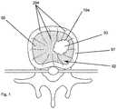
- FIG. 1illustrates a top schematic view of a target location in a vertebral bone
- FIG. 2Aillustrates a top schematic view of the target location and the positioning of a first bipolar probe and a second bipolar probe in a vertebral body
- FIG. 2Billustrates a side schematic view of the target location and one of the first and second bipolar probes positioned with respect thereto;
- FIG. 3illustrates a top schematic view of the positioning of the ends of the first and second bipolar probes
- FIG. 4illustrates another top schematic view of the positioning of the ends of the first and second bipolar probes
- FIG. 5illustrates still another top schematic view of the positioning of the ends of the first and second bipolar probes
- FIG. 6Aillustrates a top schematic view of the first bipolar probe and a lesion formed thereby, and includes a top radiographic view of the positioning of the distal end of the first bipolar probe having an active distal end length of 10 mm and showing an overlay depicting a length and width of a lesion formed thereby;
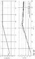
- FIG. 6Billustrates temperature and power graphs of the first bipolar probe during use thereof according to the distal end position of FIG. 6A ;
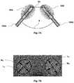
- FIG. 7Aillustrates a top schematic view of the positioning the distal ends of the first and second bipolar probes including a probe tip distance delta of 24 mm;
- FIG. 7Bis a top radiographic view of the positioning of the first and second bipolar probes having active distal end lengths of 10 mm and corresponding to FIG. 7A , and showing an overlay depicting lengths and widths of respective lesions formed thereby;
- FIG. 7Cillustrates temperature and power graphs of the first and second bipolar probes during use thereof according to the distal end positions of FIGS. 7A and 7B and the probe tip distance delta of 24 mm;
- FIG. 8Aillustrates a top schematic view of the positioning of the distal ends of the first and second bipolar probes including a probe tip distance delta of 16 mm;
- FIG. 8Bis a top radiographic view of the positioning of the first and second bipolar probes having active distal end lengths of 10 mm and corresponding to FIG. 8A , and showing an overlay depicting lengths and widths of respective lesions formed thereby;
- FIG. 8Cillustrates temperature and power graphs of the first and second bipolar probes during use thereof according to the distal end positions of FIGS. 8A and 8B and the probe tip distance delta of 16 mm;
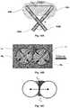
- FIG. 9Aillustrates a top schematic view of the positioning of the distal ends of the first and second bipolar probes including a probe tip distance delta of 12 mm;
- FIG. 9Bis a top radiographic view of the positioning of the first and second bipolar probes having active distal end lengths of 10 mm and corresponding to FIG. 9A , and showing an overlay depicting lengths and widths of respective lesions formed thereby;
- FIG. 9Cillustrates an extra area that may be ablated due to thermal interaction between the lesions formed by the first and second bipolar probes
- FIG. 9Dillustrates temperature and power graphs of the first and second bipolar probes during use thereof according to the distal end positions of FIGS. 9A and 9B and the probe tip distance delta of 12 mm;
- FIG. 10Aillustrates a top schematic view of the positioning of the distal ends of the first and second bipolar probes including a probe tip distance delta of 8 mm;
- FIG. 10Bis a top radiographic view of the positioning of the first and second bipolar probes having active distal end lengths of 10 mm and corresponding to FIG. 10A , and showing an overlay depicting lengths and widths of respective lesions formed thereby;
- FIG. 10Cillustrates an extra area that may be ablated due to thermal interaction between the lesions formed by the first and second bipolar probes
- FIG. 10Dillustrates temperature and power graphs of the first and second bipolar probes during use thereof according to the distal end positions of FIGS. 10A and 10B and the probe tip distance delta of 8 mm;
- FIG. 11Aillustrates a top schematic view of the positioning of the distal ends of the first and second bipolar probes including a probe tip distance delta of 4 mm;
- FIG. 11Bis a top radiographic view of the positioning of the first and second bipolar probes having active distal end lengths of 10 mm and corresponding to FIG. 11A , and showing an overlay depicting lengths and widths of respective lesions formed thereby;
- FIG. 11Cillustrates an extra area that may be ablated due to thermal interaction between the lesions formed by the first and second bipolar probes
- FIG. 11Dillustrates temperature and power graphs of the first and second bipolar probes during use thereof according to the distal end positions of FIGS. 11A and 11B and the probe tip distance delta of 4 mm;
- FIG. 12Aillustrates a top schematic view of the positioning of the distal ends of the first and second bipolar probes including a probe tip distance delta of 0 mm;
- FIG. 12Bis a top radiographic view of the positioning of the first and second bipolar probes having active distal end lengths of 10 mm and corresponding to FIG. 12A , and showing an overlay depicting lengths and widths of respective lesions formed thereby;
- FIG. 12Cillustrates an extra area that may be ablated due to thermal interaction between the lesions formed by the first and second bipolar probes
- FIG. 12Dillustrates temperature and power graphs of the first and second bipolar probes during use thereof according to the distal end positions of FIGS. 12A and 12B and the probe tip distance delta of 0 mm;
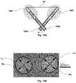
- FIG. 13Aillustrates a top schematic view of the positioning of the distal ends of the first and second bipolar probes crossing and touching one another;
- FIG. 13Bis a top radiographic view of the positioning of the first and second bipolar probes having active distal end lengths of 10 mm and corresponding to FIG. 13A , and showing an overlay depicting lengths and widths of respective lesions formed thereby;
- FIG. 13Cillustrates an extra area that may be ablated due to thermal interaction between the lesions formed by the first and second bipolar probes
- FIG. 13Dillustrates temperature and power graphs of the first and second bipolar probes during use thereof according to the distal end positions of FIGS. 13A and 13B ;
- FIG. 14Aillustrates a top schematic view of the positioning of the distal ends of the first and second bipolar probes including a probe tip distance delta of ⁇ 22 mm;
- FIG. 14Bis a top radiographic view of the positioning of the first and second bipolar probes having active distal end lengths of 10 mm and corresponding to FIG. 14A , and showing an overlay depicting lengths and widths of respective lesions formed thereby;
- FIG. 14Cillustrates an extra area that may be ablated due to thermal interaction between the lesions formed by the first and second bipolar probes
- FIG. 14Dillustrates temperature and power graphs of the first and second bipolar probes during use thereof according to the distal end positions of FIGS. 14A and 14B and the probe tip distance delta of ⁇ 22 mm;
- FIG. 15Aillustrates a top schematic view of the positioning of the distal ends of the first and second bipolar probes including a probe tip distance delta of ⁇ 30 mm;
- FIG. 15Bis a top radiographic view of the positioning of the first and second bipolar probes having active distal end lengths of 10 mm and corresponding to FIG. 15A , and showing an overlay depicting lengths and widths of respective lesions formed thereby;
- FIG. 15Cillustrates temperature and power graphs of the first and second bipolar probes during use thereof according to the distal end positions of FIGS. 15A and 15B and the probe tip distance delta of ⁇ 30 mm;
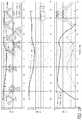
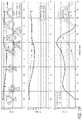
- FIGS. 16-19illustrate total delivered energy, lesion area, cooperative area, length (L), width (W), and parameter C of the first and second bipolar probes with varying distal end positions and probe tip distance deltas;
- FIG. 20illustrates another top schematic view of the first and second bipolar probes
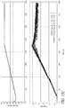
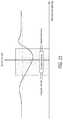
- FIG. 21illustrates a graph of total energy and probe tip distance of the first and second bipolar probes.
- a system of the present inventionwas designed to ablate a wide variety of bone tissue volumes using standard surgical access. More specifically, the present inventors have discovered a multi-probe bipolar lesioning system that allows two or more bipolar probes to be used simultaneously in order to treat bone tissue, such as within a vertebral body. For example, a medial and a posteromedial region of the vertebral body can be targeted using the multi-probe bipolar lesioning system. In some embodiments, the two probes are not delivering energy at the same instance of time. In some such embodiments, the multi-probe bipolar lesioning system comprises two bipolar probes 100 A, 100 B.
- the two bipolar probes 100 A, 100 Bmay be cooled RF bipolar probes 100 A, 100 B that each comprising coaxial bipolar ablation electrodes that are internally cooled.
- the cooled RF bipolar probes 100 A, 100 Bare usable simultaneously or individually to treat a vertebral body 92 (shown in FIG. 1 ).
- the two bipolar probes 100 A, 100 Bmay be placed within the vertebral body 92 as shown in FIGS. 2A and 2B .
- the bipolar probes 100 A, 100 Bmay be positioned adjacent a tumor 93 within the vertebral body 92 at a bone-tumor interface 194 , and may be usable to destroy nervous tissue generating pain signals at the bone-tumor interface 194 .
- the cooled RF bipolar probes 100 A, 100 Bmay be advanced into the vertebral body 92 until a distal end 102 A 142 E of each of the bipolar probes 100 A, 100 B is positioned at the bone-tumor interface 194 at the edge of the tumor 93 adjacent to nerves 294 .
- probe active tips 70 A, 70 B for each of the bipolar probes 100 A, 100 B, respectivelymay be positioned within a trabecular bone 95 within the vertebral body 92 that is encased by an electrically insulative cortical bone 97 .
- the two or more bipolar probes 100 A, 100 Bmay be positioned substantially adjacent the rich nerve supply within the vertebral body 92 .
- the bipolar probes 100 A, 100 Bmay be positioned within or substantially adjacent to the vertebral body 92 in proximity to sensitive structures such as the cortical bone 97 that may be non-conductive, or in other words, may have a low electrical conductivity.
- the target locationis the vertebral body 92 and the multi-probe bipolar system is used to treat the vertebral body 92 , as shown in FIGS. 2A and 2B .
- an introducer assemblies 4 A, 4 Bmay be used to facilitate placement of the bipolar probes 100 A, 100 B, respectively, of the multi-probe bipolar system.
- the introducer assemblies 4 A, 4 Bmay comprise a cannula with a stylet disposed therein, and may be inserted and advanced to the target location within a patient's body.
- a bi-pedicular approachis used where the multi-probe cooled RF bipolar system comprises the two bipolar probes 100 A, 100 B, where each of the bipolar probes 100 A, 100 E is advanced into the vertebral body 92 using a transpedicular approach.
- the first introducer assembly 4 Ais inserted into the vertebral body 92 using the transpedicular approach. More specifically, the first introducer assembly 4 A is inserted through the first pedicle (the right pedicle), in order to provide a trajectory to access the vertebral body 92 .
- the first bipolar probe 100 Amay then be inserted through the cannula and advanced to the target site within the vertebral body 92 .
- the second introducer assembly 4 Bis inserted into the vertebral body 92 , also using a transpedicular approach.
- the second introducer assembly 4 Bis inserted through the second pedicle (the left pedicle) and also provides a trajectory to access the vertebral body 92 .
- the second bipolar probe 1998may then be inserted through the cannula and advanced to the target site within the vertebral body 92 .
- the two bipolar probes 100 A, 100 Bare inserted and positioned within the vertebral body 92 using a bi-lateral approach to allow for substantially simultaneous lesioning using the two bipolar probes 100 A, 100 B.
- energymay be delivered through only one of the two bipolar probes 100 A, 100 B at a given moment of time.
- the introducer assemblies 4 A, 4 Bmay be inserted through the pedicle at any another suitable angle.
- the introducer assemblies 4 A, 4 Bmay be inserted through a variety of angles in the sagittal/coronal planes.
- the bipolar probes 100 A, 100 Bmay be inserted with a relative angle of 75° with respect to one another, as shown in FIGS. 3 and 4 .
- the angle of 75°may represent the nominal angle between the pedicles of a typical vertebra.
- the two bipolar probes 100 A, 100 Bmay be positioned within the vertebral body 92 using an extrapedicular approach.
- the distance between the probe active tips 70 A, 70 Bmay be varied to provide various lesion sizes.
- the angle between the bipolar probes 100 A, 100 Bmay be about 40° to facilitate access to the back or anterior region of the vertebral body 92 to permit lesioning therein.
- the angle between the two bipolar probes 100 A, 100 Bmay be about 110° to allow for access to the posterior region of the vertebral body 92 .
- the bipolar probes 100 A, 100 Bmay be inserted along a symmetric plane of the vertebral body 92 .
- the introducer assemblies 4 A, 4 Bmay be inserted through the pedicle at an angle of about 15° to about 25° oblique to the mid-sagittal plane, which provides a trajectory to access the vertebral body 92 .
- the first bipolar probe 100 Amay then be inserted through the cannula of the first introducer assembly 4 A and advanced to the target site.
- the first bipolar probe 100 Ais inserted into the vertebral body 92 at a first target location to the right of the mid-sagittal plane at an angle of about 15° to about 25° to the mid-sagittal plane.
- the second introducer assembly 4 Bmay be inserted through the second pedicle at an angle of about 15° to about 25° oblique to the mid-sagittal plane, which also provides a trajectory to access the vertebral body 92 .
- the second bipolar probe 100 Bmay then be inserted through the cannula of the second introducer assembly 4 B and advanced to the target site. As such, the second bipolar probe 100 B is inserted into the vertebral body 92 at a second target location to the left of the mid-sagittal plane at an angle of about 15° to about 25° from the mid-sagittal plane.
- energymay be supplied to the first and second bipolar probes 100 A, 100 B to allow for a first bipolar lesion 90 A to be formed at a first location within the vertebral body 92 using the first bipolar probe 100 A, and a second bipolar lesion 90 B to be formed at a second location within the vertebral body 92 using the second bipolar probe 100 B.
- thismay allow for the simultaneous use of the first and second bipolar probes 100 A, 100 B to substantially concurrently create lesions within the vertebral body 92 .
- these lesionsmay be referred to as bi-lateral lesions, where the bi-lateral lesions refer to lesions that are simultaneously created on both sides of the vertebral body 92 .
- RF electrical energyis delivered primarily on only a given probe at a moment in time.
- the system of the present inventionallows for “concurrent lesioning” using the two bipolar probes 100 A, 100 B.
- energy deliverydoes not occur simultaneously on both bipolar probes 100 A, 100 B.
- Bipolar lesions of different geometrycan be created by manipulating the duration and intensity of energy delivered through each of the bipolar probes 100 A, 100 B in the multi-probe bipolar lesioning system.
- an RF generatoris provided that supplies RF energy to each of the bipolar probes 100 A, 100 B in a bipolar manner.
- the power output of the RF generatormay be temperature controlled.
- direct tissue temperature monitoringis used in conjunction with internal cooling when supplying RF power to form a lesion. The power output may be adjusted based on the measured temperature response of the tissue to RF heating under cooling.
- the temperature response of the target tissuemay be monitored using a temperature sensor such as a thermocouple.
- the thermocouplemay be coupled to the distal ends 102 A, 102 B of the probes 100 A, 100 B.
- the two cooled RF bipolar probes 100 A, 100 Bare provided that may be used simultaneously to allow for a lesion to be created around each bipolar probe 100 A, 100 B.
- the multi-probe bipolar ablation system of the present inventionmay be used for the ablation of the vertebral body 92 , including the ablation of metastatic malignant lesions in the vertebral body 92 .
- the systempermits the two cooled RF bipolar probes 100 A, 100 B that each comprise coaxial bipolar ablation electrodes to be used simultaneously.
- the two bipolar probes 100 A, 100 Bcan be matched or mismatched in terms of the ablation volumes they generate.
- RF electrical energyis delivered on only a given bipolar probe 100 A, 100 B at a moment in time.
- energy deliverymay switch between the two bipolar probes 100 A, 109 E so rapidly that the tissue around each bipolar probe 100 A, 100 B can be heated simultaneously.
- the thermal zone of effect of each bipolar probe 100 A, 100 Bis such that it may cooperate, either positively or negatively, with the ablation zone of the other bipolar probe 100 A, 100 B.
- the angle of approach, ablation parameters, and probe sizescan be selected to create a wide variety of lesion forms and geometries.
- the ablation zonescan interact in such a way so as to ablate the posterior-medial aspect of the vertebral body 92 .
- some embodiments of the present inventionprovide the two internally cooled bipolar probes 100 A, 100 B comprising coaxial bipolar RF electrodes, and provide an algorithm for identifying the appropriate bipolar probes 100 A, 100 B, ablation parameters, and relative placement of the probes so as to achieve a desired ablation volume.
- the multi-probe bipolar ablation systemmay comprise three or more bipolar probes.
- the two internally cooled coaxial bipolar probes 100 A, 100 Bform two independent isolated systems. In some such examples, both of the bipolar probes 100 A, 100 B are capable of creating lesions simultaneously but power is not delivered to both of the bipolar probes 100 A, 100 E at the same time.
- the relationship between ablation parameters and symbiotic ablation growthmay vary.
- a method of ablating a region of tissue within the vertebral body 92comprising the following steps: (1) determining the ablation zone to be targeted within the vertebral body 92 (in some examples, this may be done pre-operatively); (2) determining the size of the lesion that would suitably cover the desired ablation zone. In some examples, this involves determining the long and short axis of the ellipsoid that could cover the ablation zone.
- This step (2)may involve additionally determining if a desired ablation zone can be effectively covered by a single RF probe. If this is the case; then the appropriate bipolar probe 100 A, 100 B is selected (either up-sized or a serial “sausage-link” chain of ablations using a down-sized RF electrode). On the other hand, if it is determined that an ablation zone is of a particular size or situated in such a position that it requires bilateral access (requiring the two RF bipolar probes 100 A, 100 B inserted through individual left and right pedicles), then the two bipolar probes 100 A, 100 B are appropriately selected. In some such embodiments, the desired volume of ablation determined by the user is matched to the ablation zone.
- the two bipolar probes 100 A, 100 Bcan be positioned relative to each other so as to symbiotically create a third zone of ablation 90 C between the two bipolar probes 100 A, 100 B, as shown in FIGS. 4 and 5 .
- the third zone of ablation 90 Cis formed through co-operative lesioning through symbiotic growth due to thermal trapping between the individual ablation zones of the two RF bipolar probes 100 A, 100 B.
- each lesiongrows independently around each of the two RF bipolar probes 100 A, 100 B until there is heating between the two ablation zones, thereby forming the third zone of ablation 90 C.
- the resultant lesionis larger than the two individual lesions that would have formed around each of the bipolar probes 100 A, 100 B in the absence of symbiosis.
- the third zone of ablation 90 Cforms as a result of the inability of the tissue between the two bipolar probes 100 A, 100 B to effectively dissipate the heat from the two bipolar probes 100 A, 100 B.
- the nature of the symbiotic growthis a function of: (i) the combination of the two RF bipolar probes used (gauge, RF electrode length, treatment temperature, treatment time).
- a graph of the symbiotic growthis provided in FIGS. 6-22 .
- a tablemay be provided that outlines the features and properties that govern the symbiotic relationship.
- RF energymay be delivered to the patient.
- the two bipolar probes 100 A, 100 Bmay be positioned relative to one another to allow for negative co-operation between the two bipolar probes 100 A, 100 B where the resultant lesion may be less than two independent lesions that would otherwise have formed around each probe 100 A, 100 B.
- the bipolar probes 100 A, 100 Bmay be positioned close to one another such that the thermocouple of one probe (e.g., the bipolar probe 100 A) sees a higher temperature due to power delivery from the other probe (e.g., the bipolar probe 100 B), which may result in the system not delivering as much power to the first bipolar probe (e.g., the bipolar probe 100 A), which may result in a smaller lesion size of the resultant lesion.
- the thermocouple of one probee.g., the bipolar probe 100 A
- the bipolar probe 100 Bsees a higher temperature due to power delivery from the other probe (e.g., the bipolar probe 100 B), which may result in the system not delivering as much power to the first bipolar probe (e.g., the bipolar probe 100 A), which may result in a smaller lesion size of the resultant lesion.
- alternate energy delivery methodssuch as ultrasound or microwave may be used that may be capable of accomplishing substantially the same outcome.
- a navigable system(steerable) may be provided.
- the navigable systemmay be used alternatively to or in conjunction with embodiments that provide for symbiotic lesion growth.
- the physicianmay attempt to access the vertebral body 92 from different angles so that the area (at least some of the area or substantially the area) that is otherwise ablated using symbiotic growth may be directly placed within the ellipsoid of a “normal” ablation zone.
- Some embodiments of the present inventionprovide a temperature controlled system where the temperature parameter is used towards/to facilitate symbiotic lesion growth.
- the system of the present inventionprovides for temperature controlled power delivery where the system comprises the two or more cooled-tip RF bipolar probes 100 A, 100 E with each probe 100 A, 100 B comprising bipolar electrodes.
- the system of the present inventionin some embodiments, is usable for ablation of bone tumors.
- some embodiments of the present inventionprovide information on the degree of symbiosis between the bipolar probes 100 A, 100 B (and lesions formed thereby) in a multi-probe bipolar system.
- the present inventionprovides for symbiotic growth of lesion between multiple cooled RF electrodes for the purposes of bone ablation.
- embodiments of the present inventionprovide a multi-probe cooled RF bipolar ablation system that facilitates ablation in bone tissue that may have reduced electrical conductivity. The system provides a means to create a symbiotic relationship during lesion formation and provides a clinical methodology that facilitates ablation accordingly.
- embodiments of the present inventioncomprise a multi-probe bipolar lesioning system that allows the two or more bipolar probes 100 A, 100 B to be used simultaneously in order to treat bone tissue.
- the systemallows for ablating a wide variety of bone tissue volumes using standard surgical access.
- the multi-probe bipolar systemis usable to treat the vertebral body 92 .
- the multi-probe bipolar systemallows for the two bipolar probes 100 A, 100 B to be positioned bilaterally (on both sides of the vertebral body 92 ) within the vertebral body 92 using a transpedicular approach to allow for substantially simultaneous lesioning within the vertebral body 92 .
- the multi-probe bipolar systemis usable to treat the vertebral body 92 having the tumor 93 therein.
- embodiments of the present inventioncomprise a multi-probe bipolar system comprising the two bipolar probes 100 A, 100 B that provides temperature controlled power delivery to allow energy to be delivered to each of the two bipolar probes 100 A, 100 B independently.
- the two bipolar probes 100 A, 100 Bare positioned relative to each other to allow for separate lesions to be created independently around each bipolar probe 100 A, 100 B.
- the two bipolar probes 100 A, 100 Bare positioned relative to each other to allow for two lesions to be created independently around each bipolar probe 100 A, 100 B, and additionally enables positive co-operation between the two bipolar probes 100 A, 100 B that allows for co-operative or symbiotic lesion growth between the two bipolar probes 100 A, 100 B, where the resultant lesion is greater than the two independent lesions that would otherwise be formed around each bipolar probe 100 A, 100 B.
- the two bipolar probes 100 A, 100 Bare positioned relative to each other to allow for negative co-operation between the two bipolar probes 100 A, 100 B where the resultant lesion is less than two independent lesions that would otherwise be formed around each bipolar probe 100 A, 100 B.
- Some embodiments of the present inventionmay utilize an RF Ablation System, including an OsteoCool RF Generator, an OsteoCool Pump, OsteoCool Extension Cable, and an OsteoCool probe having distal ends of 10 mm.
- RF Procedure Settingsmay include an RF Target temperature: 70° C., a Temperature Ramp Rate: 10° C./min, a Procedure Duration: 7:30 min, and a Maximum Power: 20 W.
- Test Mediamay include fresh chicken breast.
- Sample preparationmay include the chicken breast being immersed in hot water to reach 37° C., and thereafter placing the warmed test tissue between two acrylic plates. This setup may facilitate visualization of lesion formation and also help better understand the cooperative growth of the lesions.
- Probesare inserted into the test tissue with a relative angle ( ⁇ ) of 75° between the probes, as depicted in FIGS. 7A, 8A, 9A, 10A, 11A, 12A, 13A, 14A , and 15 A.
- probe tip distance deltas ⁇ xmay vary, as illustrated by FIGS. 7A, 8A, 9A, 10A, 11A, 12A, 13A, 14A, and 15A .
- 75°may represent an example of an angle ( ⁇ ) between the pedicles of a typical vertebra.
- FIG. 6AFormation of a single lesion using a single probe 100 A, as depicted in FIG. 6A , may be measured as a reference during testing.
- L (16 mm) and W (13 mm)denote lesion length and width, respectively, as shown in FIG. 6A .
- FIG. 6Billustrates temperature and power graphs of the probe 100 A resulting from use thereof, where the area under the power-time graph yields the total energy delivered to tissue during an ablation procedure.
- a second probe's thermocouplemay be used to identify the boundary of an ablation zone where the temperature remains around 45-50 CC.
- FIG. 9Cfurther illustrates an extra area or areas that may be ablated due to the thermal interaction of the two lesions.
- Parameter Ce.g., C 1 and C 2
- C 1is the distance between the line connecting the centers of the two lesions and the top of the extra ablated area, as shown in FIG. 9C .
- C 2is the distance between the line connecting the centers of the two lesions and the bottom of the extra ablated area, as shown in FIG. 9C . According to the orientation of FIG. 9C , this understanding for C 1 and C 2 is generally applicable to FIGS. 10C, 11C, 12C, 13C, 14C, 18, 19, and 20 .
- a negative probe tip distance delta ⁇ xindicates that the distal ends of the probes are crossing and extend past one another, as shown in FIG. 14A .
- FIGS. 16-19illustrate a drop in a total lesion area that may be expected when the bipolar probes 100 A, 100 B are placed close to one another.
- An extra ablation area of up to 11%may be expected when the process includes a probe tip distance delta ⁇ x of about 8 mm.
- the overall shape of the ablation zonemay be characterized by six parameters: L A , W A , L B , W B , C 1 , and C 2 , as shown in FIG. 20 .
- the total delivered energy and lesion area graphs of the bipolar probes 100 A, 100 Billustrate a minimum (due to cooperative heating/lesioning) that occurs when thermocouples of the bipolar probes 100 A, 100 B are placed close to one another, as shown in FIG. 21 .
- Cooperative heating/lesioningmay result in a reduction in the length and width of the lesion by up to 20%.
- an extra ablation area of 11%may result. This extra ablation area may be the result of thermal interaction between the two lesions 90 A, 90 B of the bipolar probes 100 A, 100 B.
Landscapes
- Health & Medical Sciences (AREA)
- Surgery (AREA)
- Engineering & Computer Science (AREA)
- Life Sciences & Earth Sciences (AREA)
- Biomedical Technology (AREA)
- Otolaryngology (AREA)
- Nuclear Medicine, Radiotherapy & Molecular Imaging (AREA)
- Plasma & Fusion (AREA)
- Physics & Mathematics (AREA)
- Heart & Thoracic Surgery (AREA)
- Medical Informatics (AREA)
- Molecular Biology (AREA)
- Animal Behavior & Ethology (AREA)
- General Health & Medical Sciences (AREA)
- Public Health (AREA)
- Veterinary Medicine (AREA)
- Surgical Instruments (AREA)
Abstract
Description
Claims (20)
Priority Applications (2)
| Application Number | Priority Date | Filing Date | Title |
|---|---|---|---|
| US15/387,291US10864040B2 (en) | 2015-12-29 | 2016-12-21 | Multi-probe system using bipolar probes and methods of using the same |
| US17/121,978US11617614B2 (en) | 2015-12-29 | 2020-12-15 | Multi-probe system using bipolar probes and methods of using the same |
Applications Claiming Priority (2)
| Application Number | Priority Date | Filing Date | Title |
|---|---|---|---|
| US201562272379P | 2015-12-29 | 2015-12-29 | |
| US15/387,291US10864040B2 (en) | 2015-12-29 | 2016-12-21 | Multi-probe system using bipolar probes and methods of using the same |
Related Parent Applications (1)
| Application Number | Title | Priority Date | Filing Date |
|---|---|---|---|
| US62272379Continuation | 2015-12-29 |
Related Child Applications (1)
| Application Number | Title | Priority Date | Filing Date |
|---|---|---|---|
| US17/121,978ContinuationUS11617614B2 (en) | 2015-12-29 | 2020-12-15 | Multi-probe system using bipolar probes and methods of using the same |
Publications (2)
| Publication Number | Publication Date |
|---|---|
| US20170181788A1 US20170181788A1 (en) | 2017-06-29 |
| US10864040B2true US10864040B2 (en) | 2020-12-15 |
Family
ID=59087536
Family Applications (2)
| Application Number | Title | Priority Date | Filing Date |
|---|---|---|---|
| US15/387,291Active2037-05-04US10864040B2 (en) | 2015-12-29 | 2016-12-21 | Multi-probe system using bipolar probes and methods of using the same |
| US17/121,978Active2036-10-12US11617614B2 (en) | 2015-12-29 | 2020-12-15 | Multi-probe system using bipolar probes and methods of using the same |
Family Applications After (1)
| Application Number | Title | Priority Date | Filing Date |
|---|---|---|---|
| US17/121,978Active2036-10-12US11617614B2 (en) | 2015-12-29 | 2020-12-15 | Multi-probe system using bipolar probes and methods of using the same |
Country Status (1)
| Country | Link |
|---|---|
| US (2) | US10864040B2 (en) |
Cited By (5)
| Publication number | Priority date | Publication date | Assignee | Title |
|---|---|---|---|---|
| US11974759B2 (en) | 2012-11-05 | 2024-05-07 | Relievant Medsystems, Inc. | Methods of navigation and treatment within a vertebral body |
| US12039731B2 (en) | 2020-12-22 | 2024-07-16 | Relievant Medsystems, Inc. | Prediction of candidates for spinal neuromodulation |
| US12059193B2 (en) | 2011-12-30 | 2024-08-13 | Relievant Medsystems, Inc. | Methods of denervating vertebral body using external energy source |
| US12082876B1 (en) | 2020-09-28 | 2024-09-10 | Relievant Medsystems, Inc. | Introducer drill |
| US12433668B1 (en) | 2021-11-08 | 2025-10-07 | Relievant Medsystems, Inc. | Impedance stoppage mitigation during radiofrequency tissue ablation procedures |
Families Citing this family (15)
| Publication number | Priority date | Publication date | Assignee | Title |
|---|---|---|---|---|
| US8361067B2 (en) | 2002-09-30 | 2013-01-29 | Relievant Medsystems, Inc. | Methods of therapeutically heating a vertebral body to treat back pain |
| US7258690B2 (en) | 2003-03-28 | 2007-08-21 | Relievant Medsystems, Inc. | Windowed thermal ablation probe |
| US6907884B2 (en) | 2002-09-30 | 2005-06-21 | Depay Acromed, Inc. | Method of straddling an intraosseous nerve |
| US10028753B2 (en) | 2008-09-26 | 2018-07-24 | Relievant Medsystems, Inc. | Spine treatment kits |
| CA2737374C (en) | 2008-09-26 | 2017-03-28 | Relievant Medsystems, Inc. | Systems and methods for navigating an instrument through bone |
| US10588691B2 (en) | 2012-09-12 | 2020-03-17 | Relievant Medsystems, Inc. | Radiofrequency ablation of tissue within a vertebral body |
| US9724151B2 (en) | 2013-08-08 | 2017-08-08 | Relievant Medsystems, Inc. | Modulating nerves within bone using bone fasteners |
| USD912762S1 (en) | 2017-11-29 | 2021-03-09 | Megadyne Medical Products, Inc. | Fluid trap |
| US10758856B2 (en) | 2017-11-29 | 2020-09-01 | Megadyne Medical Products, Inc. | Filter medium compression system for smoke evacuation |
| US11725664B2 (en) | 2017-11-29 | 2023-08-15 | Megadyne Medical Products, Inc. | Noise and vibration management for smoke evacuation system |
| US11234754B2 (en) | 2017-11-29 | 2022-02-01 | Megadyne Medical Products, Inc. | Smoke evacuation device |
| US10758855B2 (en) | 2017-11-29 | 2020-09-01 | Megadyne Medical Products, Inc. | Smoke evacuation system fluid trap |
| WO2019183624A1 (en)* | 2018-03-23 | 2019-09-26 | Avent, Inc. | System and method for controlling energy delivered to an area of tissue during a treatment procedure |
| AU2020346827A1 (en) | 2019-09-12 | 2022-03-31 | Relievant Medsystems, Inc. | Systems and methods for tissue modulation |
| WO2024146780A1 (en)* | 2023-01-04 | 2024-07-11 | Medtronic Holding Company Sàrl | Cross-probe ablation split hub and methods of using the same |
Citations (85)
| Publication number | Priority date | Publication date | Assignee | Title |
|---|---|---|---|---|
| US5370675A (en) | 1992-08-12 | 1994-12-06 | Vidamed, Inc. | Medical probe device and method |
| US5383874A (en) | 1991-11-08 | 1995-01-24 | Ep Technologies, Inc. | Systems for identifying catheters and monitoring their use |
| US5391199A (en) | 1993-07-20 | 1995-02-21 | Biosense, Inc. | Apparatus and method for treating cardiac arrhythmias |
| US5472441A (en) | 1993-11-08 | 1995-12-05 | Zomed International | Device for treating cancer and non-malignant tumors and methods |
| US5505730A (en) | 1994-06-24 | 1996-04-09 | Stuart D. Edwards | Thin layer ablation apparatus |
| US5536267A (en) | 1993-11-08 | 1996-07-16 | Zomed International | Multiple electrode ablation apparatus |
| US5582609A (en) | 1993-10-14 | 1996-12-10 | Ep Technologies, Inc. | Systems and methods for forming large lesions in body tissue using curvilinear electrode elements |
| US20010047167A1 (en)* | 2000-02-03 | 2001-11-29 | Heggeness Michael H. | Methods and devices for intraosseous nerve ablation |
| US6332089B1 (en) | 1996-02-15 | 2001-12-18 | Biosense, Inc. | Medical procedures and apparatus using intrabody probes |
| US6575969B1 (en) | 1995-05-04 | 2003-06-10 | Sherwood Services Ag | Cool-tip radiofrequency thermosurgery electrode system for tumor ablation |
| US6690963B2 (en) | 1995-01-24 | 2004-02-10 | Biosense, Inc. | System for determining the location and orientation of an invasive medical instrument |
| US20050004563A1 (en) | 2003-07-01 | 2005-01-06 | Racz N. Sandor | Apparatus and methods for sensing and cooling during application of thermal energy for treating degenerative spinal discs |
| US20050177210A1 (en)* | 2002-03-05 | 2005-08-11 | Baylis Medical Company Inc. | Electrosurgical tissue treatment method |
| US20050209659A1 (en)* | 2002-09-30 | 2005-09-22 | Richard Pellegrino | Method of straddling an intraosseous nerve |
| US20060200121A1 (en) | 2005-03-03 | 2006-09-07 | Mowery Thomas M | Navigable, multi-positional and variable tissue ablation apparatus and methods |
| US7167748B2 (en) | 1996-01-08 | 2007-01-23 | Impulse Dynamics Nv | Electrical muscle controller |
| US20070027449A1 (en)* | 2002-03-05 | 2007-02-01 | Baylis Medical Company Inc. | Electrosurgical device and methods |
| US20070112348A1 (en) | 1993-05-10 | 2007-05-17 | Arthrocare Corporation | Methods for electrosurgical tissue treatment between spaced apart electrodes |
| US7238182B2 (en) | 2003-04-25 | 2007-07-03 | Medtronic, Inc. | Device and method for transurethral prostate treatment |
| US20070179497A1 (en) | 1992-01-07 | 2007-08-02 | Arthrocare Corporation | System and method for electrosurgical cutting and ablation |
| US7257450B2 (en) | 2003-02-13 | 2007-08-14 | Coaptus Medical Corporation | Systems and methods for securing cardiovascular tissue |
| US7266414B2 (en) | 2003-10-24 | 2007-09-04 | Syntach, Ag | Methods and devices for creating electrical block at specific sites in cardiac tissue with targeted tissue ablation |
| US7318823B2 (en) | 1995-04-13 | 2008-01-15 | Arthrocare Corporation | Methods for repairing damaged intervertebral discs |
| US20080021447A1 (en) | 1998-08-11 | 2008-01-24 | Arthrocare Corporation | Instrument for electrosurgical tissue treatment |
| US7335196B2 (en) | 1993-10-15 | 2008-02-26 | Ep Technologies, Inc. | Systems and methods for creating long, thin lesions in body tissue |
| US7354436B2 (en) | 2003-11-14 | 2008-04-08 | Boston Scientific Scimed, Inc. | Systems and methods for performing simultaneous ablation |
| US7367974B2 (en) | 2004-09-20 | 2008-05-06 | Wisconsin Alumni Research Foundation | Electrode array for tissue ablation |
| US20080281312A1 (en) | 2007-05-11 | 2008-11-13 | Ablation Frontiers, Inc. | Ablation Therapy System and Method for Treating Continuous Atrial Fibrillation |
| WO2008142686A2 (en) | 2007-05-21 | 2008-11-27 | Uc-Care Ltd. | Ablation probe |
| US20090005774A1 (en) | 2007-02-09 | 2009-01-01 | Boston Scientific Scimed, Inc. | Medical probe with echogenic and insulative properties |
| CN100460031C (en) | 2000-04-13 | 2009-02-11 | 效思因(加拿大)有限责任公司 | Method and apparatus for treating breast lesions using microwaves |
| US7530980B2 (en) | 2004-04-14 | 2009-05-12 | Atricure, Inc | Bipolar transmural ablation method and apparatus |
| US20090171340A1 (en) | 2007-12-28 | 2009-07-02 | Boston Scientific Scimed, Inc. | Electrosurgical probe having conductive outer surface to initiate ablation between electrode |
| US7601149B2 (en) | 2005-03-07 | 2009-10-13 | Boston Scientific Scimed, Inc. | Apparatus for switching nominal and attenuated power between ablation probes |
| US20090269317A1 (en) | 2008-04-29 | 2009-10-29 | Davalos Rafael V | Irreversible electroporation to create tissue scaffolds |
| US20090287202A1 (en) | 2008-05-15 | 2009-11-19 | Boston Scientific Scimed, Inc. | Apparatus and methods for cryogenically ablating tissue and adjusting cryogenic ablation regions |
| WO2010009150A1 (en) | 2008-07-14 | 2010-01-21 | Primaeva Medical, Inc. | Devices and methods for percutaneous energy delivery |
| US7678108B2 (en) | 2004-06-02 | 2010-03-16 | Medtronic, Inc. | Loop ablation apparatus and method |
| US20100130976A1 (en) | 2008-11-21 | 2010-05-27 | Smith & Nephew Inc. | Reducing cross-talk effects in an rf electrosurgical device |
| US20100152725A1 (en) | 2008-12-12 | 2010-06-17 | Angiodynamics, Inc. | Method and system for tissue treatment utilizing irreversible electroporation and thermal track coagulation |
| US20100168725A1 (en) | 2008-12-23 | 2010-07-01 | Alexei Babkin | Isotherm-based tissue ablation control system |
| GB2453601B (en) | 2007-10-12 | 2010-07-21 | Cardio Logic Innovations Ltd | Radio frequency catheter for the ablation of body tissues |
| US7776035B2 (en) | 2004-10-08 | 2010-08-17 | Covidien Ag | Cool-tip combined electrode introducer |
| EP1493397B1 (en) | 1997-07-25 | 2011-09-14 | Covidien AG | Cluster ablation electrode system |
| US20110230874A1 (en) | 2005-07-01 | 2011-09-22 | Halt Medical Inc. | Ablation method |
| US20110238057A1 (en) | 2010-02-16 | 2011-09-29 | Angiodynamics, Inc. | Dual Bracketed Energy Delivery Probe and Method of Use |
| US20110288543A1 (en) | 2010-05-20 | 2011-11-24 | Cheng Elbert T | High frequency alternating current medical device with self-limiting conductive material and method |
| US20120046656A1 (en) | 2010-08-23 | 2012-02-23 | Tyco Healthcare Group Lp | Ablation Devices Utilizing Exothermic Chemical Reactions, System Including Same, and Methods of Ablating Tissue Using Same |
| US20120095459A1 (en) | 2010-10-13 | 2012-04-19 | Peter Callas | System and Method for Electrically Ablating Tissue of a Patient |
| US8182477B2 (en) | 2004-10-08 | 2012-05-22 | Covidien Ag | Electrosurgical system employing multiple electrodes and method thereof |
| US20120172872A1 (en) | 2010-12-23 | 2012-07-05 | Georg Nollert | Pair of endocardial and epicardial catheters, catheter and method for positioning electrodes on a cardiac wall and method for the ablation of cardiac muscle tissue |
| US20120310230A1 (en) | 2011-06-01 | 2012-12-06 | Angiodynamics, Inc. | Coaxial dual function probe and method of use |
| AU2012200903B2 (en) | 2004-08-25 | 2013-01-10 | Avent, Inc. | Bipolar electrosurgical system |
| US8361067B2 (en) | 2002-09-30 | 2013-01-29 | Relievant Medsystems, Inc. | Methods of therapeutically heating a vertebral body to treat back pain |
| US20130096549A1 (en) | 2011-10-15 | 2013-04-18 | Diros Technology Inc. | Method and apparatus for precisely controlling the size and shape of radiofrequency ablations |
| US20140022245A1 (en) | 2009-04-01 | 2014-01-23 | Covidien Lp | Microwave ablation system and user-controlled ablation size and method of use |
| US20140025066A1 (en) | 2012-07-19 | 2014-01-23 | Covidien Lp | Ablation needle including fiber bragg grating |
| US8734439B2 (en) | 1995-08-15 | 2014-05-27 | Angiodynamics, Inc | Ablation apparatus and method |
| US20140257265A1 (en) | 2013-03-07 | 2014-09-11 | Baylis Medical Company Inc. | Systems and methods for track coagulation |
| US20140276702A1 (en) | 2013-03-15 | 2014-09-18 | Warsaw Orthopedic, Inc. | Nerve and soft tissue ablation device and method |
| US9008793B1 (en) | 2007-10-15 | 2015-04-14 | Chenes Llc | Multiple electrode radiofrequency generator |
| EP2874707A1 (en) | 2012-07-23 | 2015-05-27 | LaZure Scientific, Inc. | Systems, methods and devices for precision high-intensity focused ultrasound |
| US9044245B2 (en) | 2011-01-05 | 2015-06-02 | Medtronic Ablation Frontiers Llc | Multipolarity epicardial radiofrequency ablation |
| US20150238251A1 (en) | 2009-09-22 | 2015-08-27 | Mederi Therapeutics, Inc. | Systems and methods for treating tissue with radiofrequency energy |
| WO2015200518A1 (en) | 2014-06-24 | 2015-12-30 | Apama Medical, Inc. | Tissue ablation and monitoring thereof |
| US20160058492A1 (en) | 2014-08-26 | 2016-03-03 | Ethicon Endo-Surgery, Inc. | Managing tissue treatment |
| US20160058493A1 (en) | 2014-08-28 | 2016-03-03 | Angiodynamics, Inc. | System and method for ablating a tissue site by electroporation with real-time pulse monitoring |
| US9289618B1 (en) | 1996-01-08 | 2016-03-22 | Impulse Dynamics Nv | Electrical muscle controller |
| US9345537B2 (en) | 2010-12-30 | 2016-05-24 | Avent, Inc. | Electrosurgical tissue treatment method |
| EP3030185A1 (en) | 2013-08-06 | 2016-06-15 | Memorial Sloan Kettering Cancer Center | System, method and computer-accessible medium for in-vivo tissue ablation and/or damage |
| WO2016123608A2 (en) | 2015-01-30 | 2016-08-04 | Rfemb Holdings, Llc | Radio-frequency electrical membrane breakdown for the treatment of high risk and recurrent prostate cancer, unresectable pancreatic cancer, tumors of the breast, melanoma or other skin malignancies, sarcoma, soft tissue tumors, ductal carcinoma, neoplasia, and intra and extra luminal abnormal tissue |
| WO2016126778A1 (en) | 2015-02-04 | 2016-08-11 | Rfemb Holdings, Llc | Radio-frequency electrical membrane breakdown for the treatment of benign prostatic hyperplasia |
| WO2016127162A1 (en) | 2015-02-06 | 2016-08-11 | Rfemb Holdings, Llc | Radio-frequency electrical membrane breakdown for the treatment of cardiac rhythm disorders and for renal neuromodulation |
| US20160235471A1 (en) | 2012-10-25 | 2016-08-18 | Kyphon SÀRL | Surgical Mapping Tools & Methods |
| WO2016148954A1 (en) | 2015-03-14 | 2016-09-22 | K2M, Inc. | Vertebral ablation system |
| US20160270845A1 (en) | 2015-03-19 | 2016-09-22 | Medtronic, Inc. | Coronary sinus mitral isthmus ablation catheter |
| US20160270841A1 (en) | 2015-03-17 | 2016-09-22 | Ethicon Endo-Surgery, Llc | Managing tissue treatment |
| US9474573B2 (en) | 2002-03-05 | 2016-10-25 | Avent, Inc. | Electrosurgical tissue treatment device |
| US20170000553A1 (en) | 2015-06-30 | 2017-01-05 | Ethicon Endo-Surgery, Llc | Surgical system with user adaptable techniques employing multiple energy modalities based on tissue parameters |
| US9539052B2 (en) | 1998-02-19 | 2017-01-10 | Mederi Therapeutics, Inc. | Sphincter treatment apparatus |
| US20170049513A1 (en) | 2009-11-06 | 2017-02-23 | Cosman Medical, Inc. | Multiple electrode generator |
| WO2017031362A1 (en) | 2015-08-19 | 2017-02-23 | Northwestern University | Ablation devices and methods |
| US20170049503A1 (en)* | 2014-05-15 | 2017-02-23 | Cosman Medical, Inc. | Electrosurgical system |
| EP3137006A1 (en) | 2014-04-28 | 2017-03-08 | Warsaw Orthopedic, Inc. | Devices and methods for radiofrequency ablation having an inflatable anchor member |
| US9610110B2 (en) | 2004-12-06 | 2017-04-04 | Dfine, Inc. | Bone treatment systems and methods |
- 2016
- 2016-12-21USUS15/387,291patent/US10864040B2/enactiveActive
- 2020
- 2020-12-15USUS17/121,978patent/US11617614B2/enactiveActive
Patent Citations (92)
| Publication number | Priority date | Publication date | Assignee | Title |
|---|---|---|---|---|
| US5383874A (en) | 1991-11-08 | 1995-01-24 | Ep Technologies, Inc. | Systems for identifying catheters and monitoring their use |
| US20090069807A1 (en) | 1992-01-07 | 2009-03-12 | Arthrocare Corporation | System and method for electrosurgical cutting and ablation |
| US7507236B2 (en) | 1992-01-07 | 2009-03-24 | Arthrocare Corporation | System and method for electrosurgical cutting and ablation |
| US20070179497A1 (en) | 1992-01-07 | 2007-08-02 | Arthrocare Corporation | System and method for electrosurgical cutting and ablation |
| US7819863B2 (en) | 1992-01-07 | 2010-10-26 | Arthrocare Corporation | System and method for electrosurgical cutting and ablation |
| US5370675A (en) | 1992-08-12 | 1994-12-06 | Vidamed, Inc. | Medical probe device and method |
| US7445618B2 (en) | 1993-05-10 | 2008-11-04 | Arthrocare Corporation | Methods for tissue ablation using pulsed energy |
| US20070112348A1 (en) | 1993-05-10 | 2007-05-17 | Arthrocare Corporation | Methods for electrosurgical tissue treatment between spaced apart electrodes |
| US5391199A (en) | 1993-07-20 | 1995-02-21 | Biosense, Inc. | Apparatus and method for treating cardiac arrhythmias |
| US5582609A (en) | 1993-10-14 | 1996-12-10 | Ep Technologies, Inc. | Systems and methods for forming large lesions in body tissue using curvilinear electrode elements |
| US7335196B2 (en) | 1993-10-15 | 2008-02-26 | Ep Technologies, Inc. | Systems and methods for creating long, thin lesions in body tissue |
| US5536267A (en) | 1993-11-08 | 1996-07-16 | Zomed International | Multiple electrode ablation apparatus |
| US5472441A (en) | 1993-11-08 | 1995-12-05 | Zomed International | Device for treating cancer and non-malignant tumors and methods |
| US5505730A (en) | 1994-06-24 | 1996-04-09 | Stuart D. Edwards | Thin layer ablation apparatus |
| US6690963B2 (en) | 1995-01-24 | 2004-02-10 | Biosense, Inc. | System for determining the location and orientation of an invasive medical instrument |
| US7318823B2 (en) | 1995-04-13 | 2008-01-15 | Arthrocare Corporation | Methods for repairing damaged intervertebral discs |
| US6575969B1 (en) | 1995-05-04 | 2003-06-10 | Sherwood Services Ag | Cool-tip radiofrequency thermosurgery electrode system for tumor ablation |
| US8734439B2 (en) | 1995-08-15 | 2014-05-27 | Angiodynamics, Inc | Ablation apparatus and method |
| US9289618B1 (en) | 1996-01-08 | 2016-03-22 | Impulse Dynamics Nv | Electrical muscle controller |
| US7167748B2 (en) | 1996-01-08 | 2007-01-23 | Impulse Dynamics Nv | Electrical muscle controller |
| US6332089B1 (en) | 1996-02-15 | 2001-12-18 | Biosense, Inc. | Medical procedures and apparatus using intrabody probes |
| EP1493397B1 (en) | 1997-07-25 | 2011-09-14 | Covidien AG | Cluster ablation electrode system |
| US9539052B2 (en) | 1998-02-19 | 2017-01-10 | Mederi Therapeutics, Inc. | Sphincter treatment apparatus |
| US20080021447A1 (en) | 1998-08-11 | 2008-01-24 | Arthrocare Corporation | Instrument for electrosurgical tissue treatment |
| US8663216B2 (en) | 1998-08-11 | 2014-03-04 | Paul O. Davison | Instrument for electrosurgical tissue treatment |
| US20010047167A1 (en)* | 2000-02-03 | 2001-11-29 | Heggeness Michael H. | Methods and devices for intraosseous nerve ablation |
| CN100460031C (en) | 2000-04-13 | 2009-02-11 | 效思因(加拿大)有限责任公司 | Method and apparatus for treating breast lesions using microwaves |
| US9474573B2 (en) | 2002-03-05 | 2016-10-25 | Avent, Inc. | Electrosurgical tissue treatment device |
| US20070027449A1 (en)* | 2002-03-05 | 2007-02-01 | Baylis Medical Company Inc. | Electrosurgical device and methods |
| US20050177210A1 (en)* | 2002-03-05 | 2005-08-11 | Baylis Medical Company Inc. | Electrosurgical tissue treatment method |
| US20050209659A1 (en)* | 2002-09-30 | 2005-09-22 | Richard Pellegrino | Method of straddling an intraosseous nerve |
| US8361067B2 (en) | 2002-09-30 | 2013-01-29 | Relievant Medsystems, Inc. | Methods of therapeutically heating a vertebral body to treat back pain |
| US7257450B2 (en) | 2003-02-13 | 2007-08-14 | Coaptus Medical Corporation | Systems and methods for securing cardiovascular tissue |
| US7238182B2 (en) | 2003-04-25 | 2007-07-03 | Medtronic, Inc. | Device and method for transurethral prostate treatment |
| US20050004563A1 (en) | 2003-07-01 | 2005-01-06 | Racz N. Sandor | Apparatus and methods for sensing and cooling during application of thermal energy for treating degenerative spinal discs |
| US7266414B2 (en) | 2003-10-24 | 2007-09-04 | Syntach, Ag | Methods and devices for creating electrical block at specific sites in cardiac tissue with targeted tissue ablation |
| US7354436B2 (en) | 2003-11-14 | 2008-04-08 | Boston Scientific Scimed, Inc. | Systems and methods for performing simultaneous ablation |
| US7530980B2 (en) | 2004-04-14 | 2009-05-12 | Atricure, Inc | Bipolar transmural ablation method and apparatus |
| US7678108B2 (en) | 2004-06-02 | 2010-03-16 | Medtronic, Inc. | Loop ablation apparatus and method |
| AU2012200903B2 (en) | 2004-08-25 | 2013-01-10 | Avent, Inc. | Bipolar electrosurgical system |
| US7367974B2 (en) | 2004-09-20 | 2008-05-06 | Wisconsin Alumni Research Foundation | Electrode array for tissue ablation |
| US7776035B2 (en) | 2004-10-08 | 2010-08-17 | Covidien Ag | Cool-tip combined electrode introducer |
| US8182477B2 (en) | 2004-10-08 | 2012-05-22 | Covidien Ag | Electrosurgical system employing multiple electrodes and method thereof |
| US9610110B2 (en) | 2004-12-06 | 2017-04-04 | Dfine, Inc. | Bone treatment systems and methods |
| US20060200121A1 (en) | 2005-03-03 | 2006-09-07 | Mowery Thomas M | Navigable, multi-positional and variable tissue ablation apparatus and methods |
| US7601149B2 (en) | 2005-03-07 | 2009-10-13 | Boston Scientific Scimed, Inc. | Apparatus for switching nominal and attenuated power between ablation probes |
| US20110230874A1 (en) | 2005-07-01 | 2011-09-22 | Halt Medical Inc. | Ablation method |
| US20090005774A1 (en) | 2007-02-09 | 2009-01-01 | Boston Scientific Scimed, Inc. | Medical probe with echogenic and insulative properties |
| US20080281312A1 (en) | 2007-05-11 | 2008-11-13 | Ablation Frontiers, Inc. | Ablation Therapy System and Method for Treating Continuous Atrial Fibrillation |
| WO2008142686A2 (en) | 2007-05-21 | 2008-11-27 | Uc-Care Ltd. | Ablation probe |
| WO2008142686A3 (en) | 2007-05-21 | 2009-05-07 | Uc Care Ltd | Ablation probe |
| GB2453601B (en) | 2007-10-12 | 2010-07-21 | Cardio Logic Innovations Ltd | Radio frequency catheter for the ablation of body tissues |
| US9008793B1 (en) | 2007-10-15 | 2015-04-14 | Chenes Llc | Multiple electrode radiofrequency generator |
| US20090171340A1 (en) | 2007-12-28 | 2009-07-02 | Boston Scientific Scimed, Inc. | Electrosurgical probe having conductive outer surface to initiate ablation between electrode |
| US20090269317A1 (en) | 2008-04-29 | 2009-10-29 | Davalos Rafael V | Irreversible electroporation to create tissue scaffolds |
| US9598691B2 (en) | 2008-04-29 | 2017-03-21 | Virginia Tech Intellectual Properties, Inc. | Irreversible electroporation to create tissue scaffolds |
| US20090287202A1 (en) | 2008-05-15 | 2009-11-19 | Boston Scientific Scimed, Inc. | Apparatus and methods for cryogenically ablating tissue and adjusting cryogenic ablation regions |
| WO2010009150A1 (en) | 2008-07-14 | 2010-01-21 | Primaeva Medical, Inc. | Devices and methods for percutaneous energy delivery |
| US20100130976A1 (en) | 2008-11-21 | 2010-05-27 | Smith & Nephew Inc. | Reducing cross-talk effects in an rf electrosurgical device |
| US20100152725A1 (en) | 2008-12-12 | 2010-06-17 | Angiodynamics, Inc. | Method and system for tissue treatment utilizing irreversible electroporation and thermal track coagulation |
| US20100168725A1 (en) | 2008-12-23 | 2010-07-01 | Alexei Babkin | Isotherm-based tissue ablation control system |
| US20140022245A1 (en) | 2009-04-01 | 2014-01-23 | Covidien Lp | Microwave ablation system and user-controlled ablation size and method of use |
| US20150238251A1 (en) | 2009-09-22 | 2015-08-27 | Mederi Therapeutics, Inc. | Systems and methods for treating tissue with radiofrequency energy |
| US20170049513A1 (en) | 2009-11-06 | 2017-02-23 | Cosman Medical, Inc. | Multiple electrode generator |
| US20110238057A1 (en) | 2010-02-16 | 2011-09-29 | Angiodynamics, Inc. | Dual Bracketed Energy Delivery Probe and Method of Use |
| US20110288543A1 (en) | 2010-05-20 | 2011-11-24 | Cheng Elbert T | High frequency alternating current medical device with self-limiting conductive material and method |
| US20120046656A1 (en) | 2010-08-23 | 2012-02-23 | Tyco Healthcare Group Lp | Ablation Devices Utilizing Exothermic Chemical Reactions, System Including Same, and Methods of Ablating Tissue Using Same |
| US20120095459A1 (en) | 2010-10-13 | 2012-04-19 | Peter Callas | System and Method for Electrically Ablating Tissue of a Patient |
| US20120172872A1 (en) | 2010-12-23 | 2012-07-05 | Georg Nollert | Pair of endocardial and epicardial catheters, catheter and method for positioning electrodes on a cardiac wall and method for the ablation of cardiac muscle tissue |
| US9345537B2 (en) | 2010-12-30 | 2016-05-24 | Avent, Inc. | Electrosurgical tissue treatment method |
| US9044245B2 (en) | 2011-01-05 | 2015-06-02 | Medtronic Ablation Frontiers Llc | Multipolarity epicardial radiofrequency ablation |
| US20120310230A1 (en) | 2011-06-01 | 2012-12-06 | Angiodynamics, Inc. | Coaxial dual function probe and method of use |
| US20130096549A1 (en) | 2011-10-15 | 2013-04-18 | Diros Technology Inc. | Method and apparatus for precisely controlling the size and shape of radiofrequency ablations |
| US20140025066A1 (en) | 2012-07-19 | 2014-01-23 | Covidien Lp | Ablation needle including fiber bragg grating |
| EP2874707A1 (en) | 2012-07-23 | 2015-05-27 | LaZure Scientific, Inc. | Systems, methods and devices for precision high-intensity focused ultrasound |
| US20160235471A1 (en) | 2012-10-25 | 2016-08-18 | Kyphon SÀRL | Surgical Mapping Tools & Methods |
| US20140257265A1 (en) | 2013-03-07 | 2014-09-11 | Baylis Medical Company Inc. | Systems and methods for track coagulation |
| US20140276702A1 (en) | 2013-03-15 | 2014-09-18 | Warsaw Orthopedic, Inc. | Nerve and soft tissue ablation device and method |
| EP3030185A1 (en) | 2013-08-06 | 2016-06-15 | Memorial Sloan Kettering Cancer Center | System, method and computer-accessible medium for in-vivo tissue ablation and/or damage |
| EP3137006A1 (en) | 2014-04-28 | 2017-03-08 | Warsaw Orthopedic, Inc. | Devices and methods for radiofrequency ablation having an inflatable anchor member |
| US20170049503A1 (en)* | 2014-05-15 | 2017-02-23 | Cosman Medical, Inc. | Electrosurgical system |
| WO2015200518A1 (en) | 2014-06-24 | 2015-12-30 | Apama Medical, Inc. | Tissue ablation and monitoring thereof |
| US20160058492A1 (en) | 2014-08-26 | 2016-03-03 | Ethicon Endo-Surgery, Inc. | Managing tissue treatment |
| US20160058493A1 (en) | 2014-08-28 | 2016-03-03 | Angiodynamics, Inc. | System and method for ablating a tissue site by electroporation with real-time pulse monitoring |
| WO2016123608A2 (en) | 2015-01-30 | 2016-08-04 | Rfemb Holdings, Llc | Radio-frequency electrical membrane breakdown for the treatment of high risk and recurrent prostate cancer, unresectable pancreatic cancer, tumors of the breast, melanoma or other skin malignancies, sarcoma, soft tissue tumors, ductal carcinoma, neoplasia, and intra and extra luminal abnormal tissue |
| WO2016126778A1 (en) | 2015-02-04 | 2016-08-11 | Rfemb Holdings, Llc | Radio-frequency electrical membrane breakdown for the treatment of benign prostatic hyperplasia |
| WO2016127162A1 (en) | 2015-02-06 | 2016-08-11 | Rfemb Holdings, Llc | Radio-frequency electrical membrane breakdown for the treatment of cardiac rhythm disorders and for renal neuromodulation |
| WO2016148954A1 (en) | 2015-03-14 | 2016-09-22 | K2M, Inc. | Vertebral ablation system |
| US20160270841A1 (en) | 2015-03-17 | 2016-09-22 | Ethicon Endo-Surgery, Llc | Managing tissue treatment |
| US20160270845A1 (en) | 2015-03-19 | 2016-09-22 | Medtronic, Inc. | Coronary sinus mitral isthmus ablation catheter |
| US20170000553A1 (en) | 2015-06-30 | 2017-01-05 | Ethicon Endo-Surgery, Llc | Surgical system with user adaptable techniques employing multiple energy modalities based on tissue parameters |
| WO2017031362A1 (en) | 2015-08-19 | 2017-02-23 | Northwestern University | Ablation devices and methods |
Cited By (5)
| Publication number | Priority date | Publication date | Assignee | Title |
|---|---|---|---|---|
| US12059193B2 (en) | 2011-12-30 | 2024-08-13 | Relievant Medsystems, Inc. | Methods of denervating vertebral body using external energy source |
| US11974759B2 (en) | 2012-11-05 | 2024-05-07 | Relievant Medsystems, Inc. | Methods of navigation and treatment within a vertebral body |
| US12082876B1 (en) | 2020-09-28 | 2024-09-10 | Relievant Medsystems, Inc. | Introducer drill |
| US12039731B2 (en) | 2020-12-22 | 2024-07-16 | Relievant Medsystems, Inc. | Prediction of candidates for spinal neuromodulation |
| US12433668B1 (en) | 2021-11-08 | 2025-10-07 | Relievant Medsystems, Inc. | Impedance stoppage mitigation during radiofrequency tissue ablation procedures |
Also Published As
| Publication number | Publication date |
|---|---|
| US20170181788A1 (en) | 2017-06-29 |
| US20210093373A1 (en) | 2021-04-01 |
| US11617614B2 (en) | 2023-04-04 |
Similar Documents
| Publication | Publication Date | Title |
|---|---|---|
| US11617614B2 (en) | Multi-probe system using bipolar probes and methods of using the same | |
| US7819869B2 (en) | Methods of treating the sacroilac region of a patient's body | |
| USRE48460E1 (en) | Method of treating an intraosseous nerve | |
| US9931161B2 (en) | Coaxial dual function probe and method of use | |
| US9949789B2 (en) | Methods of treating the sacroiliac region of a patient's body | |
| EP1932487B1 (en) | Electrosurgical system employing multiple electrodes | |
| US20070156136A1 (en) | Methods of treating the sacroiliac region of a patient's body | |
| AU2011218612B2 (en) | Method of Straddling an Intraosseous Nerve | |
| US12279805B2 (en) | Method for detecting presence of tubing in pump assembly | |
| US11291496B2 (en) | Methods of treating the sacroiliac region of a patient's body | |
| Kanakarajan | Radiofrequency techniques in pain management |
Legal Events
| Date | Code | Title | Description |
|---|---|---|---|
| AS | Assignment | Owner name:KYPHON SARL, SWITZERLAND Free format text:ASSIGNMENT OF ASSIGNORS INTEREST;ASSIGNORS:DASTJERDI, AHMAD KHAYER;HARRISON, ROBERT;GODARA, NEIL;AND OTHERS;SIGNING DATES FROM 20161220 TO 20161221;REEL/FRAME:040747/0042 | |
| AS | Assignment | Owner name:MEDTRONIC HOLDING COMPANY SARL, SWITZERLAND Free format text:ASSIGNMENT OF ASSIGNORS INTEREST;ASSIGNOR:KYPHON SARL;REEL/FRAME:046225/0001 Effective date:20180426 | |
| STPP | Information on status: patent application and granting procedure in general | Free format text:NON FINAL ACTION MAILED | |
| STPP | Information on status: patent application and granting procedure in general | Free format text:RESPONSE TO NON-FINAL OFFICE ACTION ENTERED AND FORWARDED TO EXAMINER | |
| STPP | Information on status: patent application and granting procedure in general | Free format text:FINAL REJECTION MAILED | |
| STPP | Information on status: patent application and granting procedure in general | Free format text:RESPONSE AFTER FINAL ACTION FORWARDED TO EXAMINER | |
| STPP | Information on status: patent application and granting procedure in general | Free format text:DOCKETED NEW CASE - READY FOR EXAMINATION | |
| STPP | Information on status: patent application and granting procedure in general | Free format text:NON FINAL ACTION MAILED | |
| STPP | Information on status: patent application and granting procedure in general | Free format text:RESPONSE TO NON-FINAL OFFICE ACTION ENTERED AND FORWARDED TO EXAMINER | |
| STPP | Information on status: patent application and granting procedure in general | Free format text:AWAITING TC RESP., ISSUE FEE NOT PAID | |
| STCF | Information on status: patent grant | Free format text:PATENTED CASE | |
| MAFP | Maintenance fee payment | Free format text:PAYMENT OF MAINTENANCE FEE, 4TH YEAR, LARGE ENTITY (ORIGINAL EVENT CODE: M1551); ENTITY STATUS OF PATENT OWNER: LARGE ENTITY Year of fee payment:4 | |
| AS | Assignment | Owner name:MEDTRONIC EUROPE SARL, SWITZERLAND Free format text:MERGER;ASSIGNOR:MEDTRONIC HOLDING COMPANY SARL;REEL/FRAME:070809/0661 Effective date:20241018 |