US10864039B2 - Cavitary tissue ablation system - Google Patents
Cavitary tissue ablation systemDownload PDFInfo
- Publication number
- US10864039B2 US10864039B2US15/419,256US201715419256AUS10864039B2US 10864039 B2US10864039 B2US 10864039B2US 201715419256 AUS201715419256 AUS 201715419256AUS 10864039 B2US10864039 B2US 10864039B2
- Authority
- US
- United States
- Prior art keywords
- ablation
- conductive wires
- electrode array
- tissue
- controller
- Prior art date
- Legal status (The legal status is an assumption and is not a legal conclusion. Google has not performed a legal analysis and makes no representation as to the accuracy of the status listed.)
- Active, expires
Links
Images


Classifications
- A—HUMAN NECESSITIES
- A61—MEDICAL OR VETERINARY SCIENCE; HYGIENE
- A61B—DIAGNOSIS; SURGERY; IDENTIFICATION
- A61B18/00—Surgical instruments, devices or methods for transferring non-mechanical forms of energy to or from the body
- A61B18/04—Surgical instruments, devices or methods for transferring non-mechanical forms of energy to or from the body by heating
- A61B18/12—Surgical instruments, devices or methods for transferring non-mechanical forms of energy to or from the body by heating by passing a current through the tissue to be heated, e.g. high-frequency current
- A61B18/14—Probes or electrodes therefor
- A61B18/148—Probes or electrodes therefor having a short, rigid shaft for accessing the inner body transcutaneously, e.g. for neurosurgery or arthroscopy
- A—HUMAN NECESSITIES
- A61—MEDICAL OR VETERINARY SCIENCE; HYGIENE
- A61B—DIAGNOSIS; SURGERY; IDENTIFICATION
- A61B18/00—Surgical instruments, devices or methods for transferring non-mechanical forms of energy to or from the body
- A61B18/04—Surgical instruments, devices or methods for transferring non-mechanical forms of energy to or from the body by heating
- A61B18/12—Surgical instruments, devices or methods for transferring non-mechanical forms of energy to or from the body by heating by passing a current through the tissue to be heated, e.g. high-frequency current
- A61B18/14—Probes or electrodes therefor
- A61B18/1477—Needle-like probes
- A—HUMAN NECESSITIES
- A61—MEDICAL OR VETERINARY SCIENCE; HYGIENE
- A61B—DIAGNOSIS; SURGERY; IDENTIFICATION
- A61B18/00—Surgical instruments, devices or methods for transferring non-mechanical forms of energy to or from the body
- A61B18/04—Surgical instruments, devices or methods for transferring non-mechanical forms of energy to or from the body by heating
- A61B18/12—Surgical instruments, devices or methods for transferring non-mechanical forms of energy to or from the body by heating by passing a current through the tissue to be heated, e.g. high-frequency current
- A61B18/1206—Generators therefor
- A—HUMAN NECESSITIES
- A61—MEDICAL OR VETERINARY SCIENCE; HYGIENE
- A61B—DIAGNOSIS; SURGERY; IDENTIFICATION
- A61B18/00—Surgical instruments, devices or methods for transferring non-mechanical forms of energy to or from the body
- A61B18/04—Surgical instruments, devices or methods for transferring non-mechanical forms of energy to or from the body by heating
- A61B18/12—Surgical instruments, devices or methods for transferring non-mechanical forms of energy to or from the body by heating by passing a current through the tissue to be heated, e.g. high-frequency current
- A61B18/14—Probes or electrodes therefor
- A61B18/1492—Probes or electrodes therefor having a flexible, catheter-like structure, e.g. for heart ablation
- A—HUMAN NECESSITIES
- A61—MEDICAL OR VETERINARY SCIENCE; HYGIENE
- A61B—DIAGNOSIS; SURGERY; IDENTIFICATION
- A61B90/00—Instruments, implements or accessories specially adapted for surgery or diagnosis and not covered by any of the groups A61B1/00 - A61B50/00, e.g. for luxation treatment or for protecting wound edges
- A61B90/04—Protection of tissue around surgical sites against effects of non-mechanical surgery, e.g. laser surgery
- A—HUMAN NECESSITIES
- A61—MEDICAL OR VETERINARY SCIENCE; HYGIENE
- A61B—DIAGNOSIS; SURGERY; IDENTIFICATION
- A61B17/00—Surgical instruments, devices or methods
- A61B2017/00017—Electrical control of surgical instruments
- A61B2017/00022—Sensing or detecting at the treatment site
- A61B2017/00039—Electric or electromagnetic phenomena other than conductivity, e.g. capacity, inductivity, Hall effect
- A61B2017/00044—Sensing electrocardiography, i.e. ECG
- A61B2017/00048—Spectral analysis
- A61B2017/00053—Mapping
- A—HUMAN NECESSITIES
- A61—MEDICAL OR VETERINARY SCIENCE; HYGIENE
- A61B—DIAGNOSIS; SURGERY; IDENTIFICATION
- A61B17/00—Surgical instruments, devices or methods
- A61B2017/00017—Electrical control of surgical instruments
- A61B2017/00022—Sensing or detecting at the treatment site
- A61B2017/00057—Light
- A—HUMAN NECESSITIES
- A61—MEDICAL OR VETERINARY SCIENCE; HYGIENE
- A61B—DIAGNOSIS; SURGERY; IDENTIFICATION
- A61B18/00—Surgical instruments, devices or methods for transferring non-mechanical forms of energy to or from the body
- A61B2018/00053—Mechanical features of the instrument of device
- A61B2018/0016—Energy applicators arranged in a two- or three dimensional array
- A—HUMAN NECESSITIES
- A61—MEDICAL OR VETERINARY SCIENCE; HYGIENE
- A61B—DIAGNOSIS; SURGERY; IDENTIFICATION
- A61B18/00—Surgical instruments, devices or methods for transferring non-mechanical forms of energy to or from the body
- A61B2018/00053—Mechanical features of the instrument of device
- A61B2018/00214—Expandable means emitting energy, e.g. by elements carried thereon
- A61B2018/00267—Expandable means emitting energy, e.g. by elements carried thereon having a basket shaped structure
- A—HUMAN NECESSITIES
- A61—MEDICAL OR VETERINARY SCIENCE; HYGIENE
- A61B—DIAGNOSIS; SURGERY; IDENTIFICATION
- A61B18/00—Surgical instruments, devices or methods for transferring non-mechanical forms of energy to or from the body
- A61B2018/00315—Surgical instruments, devices or methods for transferring non-mechanical forms of energy to or from the body for treatment of particular body parts
- A61B2018/00333—Breast
- A—HUMAN NECESSITIES
- A61—MEDICAL OR VETERINARY SCIENCE; HYGIENE
- A61B—DIAGNOSIS; SURGERY; IDENTIFICATION
- A61B18/00—Surgical instruments, devices or methods for transferring non-mechanical forms of energy to or from the body
- A61B2018/00571—Surgical instruments, devices or methods for transferring non-mechanical forms of energy to or from the body for achieving a particular surgical effect
- A61B2018/00577—Ablation
- A—HUMAN NECESSITIES
- A61—MEDICAL OR VETERINARY SCIENCE; HYGIENE
- A61B—DIAGNOSIS; SURGERY; IDENTIFICATION
- A61B18/00—Surgical instruments, devices or methods for transferring non-mechanical forms of energy to or from the body
- A61B2018/00636—Sensing and controlling the application of energy
- A61B2018/00642—Sensing and controlling the application of energy with feedback, i.e. closed loop control
- A61B2018/00648—Sensing and controlling the application of energy with feedback, i.e. closed loop control using more than one sensed parameter
- A—HUMAN NECESSITIES
- A61—MEDICAL OR VETERINARY SCIENCE; HYGIENE
- A61B—DIAGNOSIS; SURGERY; IDENTIFICATION
- A61B18/00—Surgical instruments, devices or methods for transferring non-mechanical forms of energy to or from the body
- A61B2018/00636—Sensing and controlling the application of energy
- A61B2018/00696—Controlled or regulated parameters
- A61B2018/00702—Power or energy
- A61B2018/00708—Power or energy switching the power on or off
- A—HUMAN NECESSITIES
- A61—MEDICAL OR VETERINARY SCIENCE; HYGIENE
- A61B—DIAGNOSIS; SURGERY; IDENTIFICATION
- A61B18/00—Surgical instruments, devices or methods for transferring non-mechanical forms of energy to or from the body
- A61B2018/00636—Sensing and controlling the application of energy
- A61B2018/00696—Controlled or regulated parameters
- A61B2018/0072—Current
- A—HUMAN NECESSITIES
- A61—MEDICAL OR VETERINARY SCIENCE; HYGIENE
- A61B—DIAGNOSIS; SURGERY; IDENTIFICATION
- A61B18/00—Surgical instruments, devices or methods for transferring non-mechanical forms of energy to or from the body
- A61B2018/00636—Sensing and controlling the application of energy
- A61B2018/00696—Controlled or regulated parameters
- A61B2018/00726—Duty cycle
- A—HUMAN NECESSITIES
- A61—MEDICAL OR VETERINARY SCIENCE; HYGIENE
- A61B—DIAGNOSIS; SURGERY; IDENTIFICATION
- A61B18/00—Surgical instruments, devices or methods for transferring non-mechanical forms of energy to or from the body
- A61B2018/00636—Sensing and controlling the application of energy
- A61B2018/00696—Controlled or regulated parameters
- A61B2018/00744—Fluid flow
- A—HUMAN NECESSITIES
- A61—MEDICAL OR VETERINARY SCIENCE; HYGIENE
- A61B—DIAGNOSIS; SURGERY; IDENTIFICATION
- A61B18/00—Surgical instruments, devices or methods for transferring non-mechanical forms of energy to or from the body
- A61B2018/00636—Sensing and controlling the application of energy
- A61B2018/00696—Controlled or regulated parameters
- A61B2018/00761—Duration
- A—HUMAN NECESSITIES
- A61—MEDICAL OR VETERINARY SCIENCE; HYGIENE
- A61B—DIAGNOSIS; SURGERY; IDENTIFICATION
- A61B18/00—Surgical instruments, devices or methods for transferring non-mechanical forms of energy to or from the body
- A61B2018/00636—Sensing and controlling the application of energy
- A61B2018/00773—Sensed parameters
- A61B2018/00791—Temperature
- A—HUMAN NECESSITIES
- A61—MEDICAL OR VETERINARY SCIENCE; HYGIENE
- A61B—DIAGNOSIS; SURGERY; IDENTIFICATION
- A61B18/00—Surgical instruments, devices or methods for transferring non-mechanical forms of energy to or from the body
- A61B2018/00636—Sensing and controlling the application of energy
- A61B2018/00773—Sensed parameters
- A61B2018/00827—Current
- A—HUMAN NECESSITIES
- A61—MEDICAL OR VETERINARY SCIENCE; HYGIENE
- A61B—DIAGNOSIS; SURGERY; IDENTIFICATION
- A61B18/00—Surgical instruments, devices or methods for transferring non-mechanical forms of energy to or from the body
- A61B2018/00636—Sensing and controlling the application of energy
- A61B2018/00773—Sensed parameters
- A61B2018/00839—Bioelectrical parameters, e.g. ECG, EEG
- A—HUMAN NECESSITIES
- A61—MEDICAL OR VETERINARY SCIENCE; HYGIENE
- A61B—DIAGNOSIS; SURGERY; IDENTIFICATION
- A61B18/00—Surgical instruments, devices or methods for transferring non-mechanical forms of energy to or from the body
- A61B2018/00636—Sensing and controlling the application of energy
- A61B2018/00773—Sensed parameters
- A61B2018/00875—Resistance or impedance
- A—HUMAN NECESSITIES
- A61—MEDICAL OR VETERINARY SCIENCE; HYGIENE
- A61B—DIAGNOSIS; SURGERY; IDENTIFICATION
- A61B18/00—Surgical instruments, devices or methods for transferring non-mechanical forms of energy to or from the body
- A61B2018/00636—Sensing and controlling the application of energy
- A61B2018/00773—Sensed parameters
- A61B2018/00886—Duration
- A—HUMAN NECESSITIES
- A61—MEDICAL OR VETERINARY SCIENCE; HYGIENE
- A61B—DIAGNOSIS; SURGERY; IDENTIFICATION
- A61B18/00—Surgical instruments, devices or methods for transferring non-mechanical forms of energy to or from the body
- A61B2018/00988—Means for storing information, e.g. calibration constants, or for preventing excessive use, e.g. usage, service life counter
- A—HUMAN NECESSITIES
- A61—MEDICAL OR VETERINARY SCIENCE; HYGIENE
- A61B—DIAGNOSIS; SURGERY; IDENTIFICATION
- A61B18/00—Surgical instruments, devices or methods for transferring non-mechanical forms of energy to or from the body
- A61B18/04—Surgical instruments, devices or methods for transferring non-mechanical forms of energy to or from the body by heating
- A61B18/12—Surgical instruments, devices or methods for transferring non-mechanical forms of energy to or from the body by heating by passing a current through the tissue to be heated, e.g. high-frequency current
- A61B18/1206—Generators therefor
- A61B2018/124—Generators therefor switching the output to different electrodes, e.g. sequentially
- A—HUMAN NECESSITIES
- A61—MEDICAL OR VETERINARY SCIENCE; HYGIENE
- A61B—DIAGNOSIS; SURGERY; IDENTIFICATION
- A61B18/00—Surgical instruments, devices or methods for transferring non-mechanical forms of energy to or from the body
- A61B18/04—Surgical instruments, devices or methods for transferring non-mechanical forms of energy to or from the body by heating
- A61B18/12—Surgical instruments, devices or methods for transferring non-mechanical forms of energy to or from the body by heating by passing a current through the tissue to be heated, e.g. high-frequency current
- A61B18/14—Probes or electrodes therefor
- A61B2018/1405—Electrodes having a specific shape
- A61B2018/1417—Ball
- A—HUMAN NECESSITIES
- A61—MEDICAL OR VETERINARY SCIENCE; HYGIENE
- A61B—DIAGNOSIS; SURGERY; IDENTIFICATION
- A61B18/00—Surgical instruments, devices or methods for transferring non-mechanical forms of energy to or from the body
- A61B18/04—Surgical instruments, devices or methods for transferring non-mechanical forms of energy to or from the body by heating
- A61B18/12—Surgical instruments, devices or methods for transferring non-mechanical forms of energy to or from the body by heating by passing a current through the tissue to be heated, e.g. high-frequency current
- A61B18/14—Probes or electrodes therefor
- A61B2018/1405—Electrodes having a specific shape
- A61B2018/144—Wire
- A—HUMAN NECESSITIES
- A61—MEDICAL OR VETERINARY SCIENCE; HYGIENE
- A61B—DIAGNOSIS; SURGERY; IDENTIFICATION
- A61B90/00—Instruments, implements or accessories specially adapted for surgery or diagnosis and not covered by any of the groups A61B1/00 - A61B50/00, e.g. for luxation treatment or for protecting wound edges
- A61B90/04—Protection of tissue around surgical sites against effects of non-mechanical surgery, e.g. laser surgery
- A61B2090/0409—Specification of type of protection measures
- A61B2090/0436—Shielding
- A—HUMAN NECESSITIES
- A61—MEDICAL OR VETERINARY SCIENCE; HYGIENE
- A61B—DIAGNOSIS; SURGERY; IDENTIFICATION
- A61B2218/00—Details of surgical instruments, devices or methods for transferring non-mechanical forms of energy to or from the body
- A61B2218/001—Details of surgical instruments, devices or methods for transferring non-mechanical forms of energy to or from the body having means for irrigation and/or aspiration of substances to and/or from the surgical site
- A61B2218/002—Irrigation
Definitions
- the present disclosurerelates generally to medical devices, and, more particularly, to system for monitoring and controlling an ablation device to cause the ablation device to emit energy in a desired shape or pattern so as to deliver treatment for the ablation and destruction of a targeted portion of marginal tissue around the tissue cavity.
- Canceris a group of diseases involving abnormal cell growth with the potential to invade or spread to other parts of the body. Cancer generally manifests into abnormal growths of tissue in the form of a tumor that may be localized to a particular area of a patient's body (e.g., associated with a specific body part or organ) or may be spread throughout. Tumors, both benign and malignant, are commonly treated and removed via surgical intervention, as surgery often offers the greatest chance for complete removal and cure, especially if the cancer has not spread to other parts of the body. Electrosurgical methods, for example, can be used to destroy these abnormal tissue growths. However, in some instances, surgery alone is insufficient to adequately remove all cancerous tissue from a local environment.
- treatment of early stage breast cancertypically involves a combination of surgery and adjuvant irradiation.
- a lumpectomyremoves only the tumor and a small rim (area) of the normal tissue around it.
- Radiation therapyis given after lumpectomy in an attempt to eradicate cancer cells that may remain in the local environment around the removed tumor, so as to lower the chances of the cancer returning.
- radiation therapy as a post-operative treatmentsuffers various shortcomings. For example, radiation techniques can be costly and time consuming, and typically involve multiple treatments over weeks and sometimes months. Furthermore, radiation often results in unintended damage to the tissue outside the target zone. Thus, rather than affecting the likely residual tissue, typically near the original tumor location, radiation techniques often adversely affect healthy tissue, such as short and long-term complications affecting the skin, lungs, and heart.
- Tumorsboth benign and malignant, are commonly treated and destroyed via surgical intervention, as surgery often offers the greatest chance for complete removal and cure, especially if the cancer has not metastasized.
- a hollow cavitymay remain, wherein tissue surrounding this cavity and surrounding the original tumor site can still leave abnormal or potentially cancerous cells that the surgeon fails, or is unable, to excise.
- This surrounding tissueis commonly referred to as “margin tissue” or “marginal tissue”, and is the location within a patient where a reoccurrence of the tumor may most likely occur.
- ablation devicesto be inserted within cavitary excisional beds and deliver radiofrequency (RF) energy to marginal tissue surrounding the cavity following the procedure.
- RFradiofrequency
- one type of proposed ablation applicatorincludes a long rigid needle-based electrode applicator for delivery of RF energy to marginal tissue upon manual manipulation by a surgeon or operator.
- Another type of ablation applicationincludes an umbrella-type array of electrodes jointly connected to one another and deployable in an umbrella-like fashion to deliver RF energy.
- While current ablation devicesmay provide some form tissue ablation, none have proven to meet all needs and circumstances encountered when performing marginal cavity tissue ablation. For example, in certain instances, it may be desirable to create a non-uniform ablation within a tissue cavity. In some instances, vital organs or critical internal/external structures (e.g., bone, muscle, skin, etc.) may be in close proximity to a tissue cavity and any unintended exposure to RF energy could have a negative impact.
- vital organs or critical internal/external structurese.g., bone, muscle, skin, etc.
- RF ablation devicesare unable to provide precise control over the emission of RF energy such that they lack the ability to effectively prevent emission from reaching vital organs or important internal/external structures during the ablation procedure.
- the long rigid needle-based electrode RF applicatorsgenerally require the surgeon or operator to manually adjust needle locations, and possibly readjust several electrodes multiple times, in order to control an ablation, which may lead to inaccuracy and difficulty in directing RF emission.
- the umbrella array RF applicatorsare limited by their physical geometry, in that the umbrella array may not be designed to fit within a cavity.
- the uniform potential distribution of an umbrella arrayresults in a tissue ablation geometry that is not adjustable without physically moving the umbrella array, thus resulting in similar problems as long rigid needle-based RF applicators.
- the system of the present disclosurecan be used during an ablation procedure to monitor ablation progress and to further control an ablation device in such a manner so as to cause the ablation device to emit energy in a desired shape or pattern so as to deliver treatment for the ablation and destruction the thin rim of marginal tissue around the cavity in a targeted manner.
- the present disclosureis generally includes a controller configured to selectively control energy emission from an electrode array of an ablation device based on ablation feedback received during an ablation procedure with the ablation device.
- the controlleris configured to receive feedback data from one or more sensors during an ablation procedure.
- the feedback dataincludes one or more measurements associated with at least one of operation of the electrode array of the ablation device and tissue adjacent to the electrode array.
- the systemmay include an ablation tracking interface module configured to receive the feedback data.
- the measurements of the feedback datamay include, but is not limited to, an elapsed time during an ablation period, electrical conductivity or complex impedance associated with one or more conductive wires of the electrode array of the ablation device, electrical current supplied to the one or more conductive wires, temperature of tissue adjacent to the electrode array, photonic properties of the tissue adjacent to the electrode array, and a combination thereof.
- the systemmay further include at least one of a temperature sensor, voltage sensor, signal detector, and impedance sensor configured to obtain measurements during an ablation procedure.
- the controlleris further configured to generate an ablation pattern for controlling energy emission from the electrode array of the ablation device in response to the received feedback data.
- the ablation patternmay include, but is not limited to, a selected one or more conductive wires from a plurality of conductive wires of the electrode array, to receive electrical current for energy emission, a level of electrical current to be supplied to a selected one or more conductive wires, a length of elapsed time during which electrical current is to be supplied to a selected one or more conductive wires, one or more intervals over which electrical current is to be supplied to a selected one or more conductive wires, and a combination thereof.
- the electrode array of the ablation devicemay include a plurality of independent conductive wires configured to independently receive electrical current. Accordingly, in some embodiments, the ablation pattern may include a selected one, or a selected set of two or more, of the plurality of conductive wires resulting in emission of energy therefrom corresponding to a portion of the electrode array, thereby resulting in targeted ablation of adjacent tissue.
- the generation of the ablation patternmay include processing the feedback data in real-, or near-real-, time and generating ablation status mapping based on the processed feedback data.
- the ablation status mappingprovides an estimation of the state of the tissue to be ablated, currently undergoing ablation, or having undergone ablation.
- the generation of the ablation status mappingmay include processing of the feedback data in accordance with at least the formula: (t, s, init_local_Z[ ], init_global_Z[ ], current_local_Z[ ], current_global_Z[ ], x, y, z) ⁇ AblationStatus, wherein ‘t’ indicates an elapsed time in seconds, ‘s’ indicates a size of an ablating end of the ablation device, ‘Z’ indicates impedance, ‘H’ indicates arrays with length of a number of conductive wires, and ‘x,y,z’ are coordinates of a sub volume of tissue.
- the generation of the ablation patternmay further include a combination of ablation status mapping data with an electrode activation algorithm for assignment of one or more ablation control parameters for selective conductive wire activation for subsequent targeted ablation of adjacent tissue.
- the systemmay include an ablation mapping module and an ablation geometry shaping module, the ablation mapping module configured to receive and process the feedback data and transmit mapping data to the ablation geometry shaping module configured to process the mapping data to generate the ablation pattern.
- the ablation geometry shaping modulemay be configured to transmit the ablation pattern to an electrode connection multiplexer controller, which is configured to supply electrical current to a selected one, or set of two or more, conductive wires in response to the ablation pattern.
- the devices, systems, and methods of the present disclosurecan help to ensure that all microscopic disease in the local environment has been treated. This is especially true in the treatment of tumors that have a tendency to recur.
- the system of the present inventionallows for non-uniform ablation to occur. This is particularly useful in controlling ablation shape so as to avoid vital organs and any critical internal/external structures (e.g., bone, muscle, skin) in close proximity to the tumor site, while ensuring that residual marginal tissue within the local environment has been treated.
- body cavitymay include non-surgically created cavities, such as natural body cavities and passages, such as the ureter (e.g. for prostate treatment), the uterus (e.g. for uterine ablation or fibroid treatment), fallopian tubes (e.g. for sterilization), and the like.
- tissue ablation devices of the present disclosuremay be used for the ablation of marginal tissue in various parts of the body and organs (e.g., lungs, liver, pancreas, etc.) and is not limited to treatment of breast cancer.
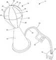
- FIG. 1is a schematic illustration of an ablation system consistent with the present disclosure
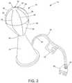
- FIG. 2is a perspective view of an ablation device tip of the ablation system of FIG. 1 ;
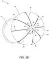
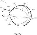
- FIGS. 3A, 3B, and 3Care perspective views of the ablation device tip of FIG. 2 in greater detail
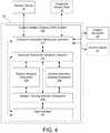
- FIG. 4is a block diagram illustrating the custom ablation system of the device controller in greater detail
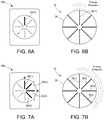
- FIG. 5is a top view of one embodiment of device controller configured for individually controlling operational modes of each of the plurality of conductive wires of the electrode array of the ablation device tip;
- FIG. 6Ais a top view of the device controller in a first mode and FIG. 6B is a front view of the ablation device tip illustrating the electrode array operating in the first mode;
- FIG. 7Ais a top view of the device controller in a second mode and FIG. 7B is a front view of the ablation device tip illustrating the electrode array operating in the second mode;
- FIGS. 8A, 8B, 8C, 8D, and 8Eare perspective views of a distal tip of the ablation device of FIG. 1 illustrating various electrode array configurations;
- FIG. 9is a side view of the distal tip of the ablation device of FIG. 1 including several clinical axes or sides.
- Each clinical axis or sideincludes one or more independently connected electrodes, which enables differential function and current independent drives and/or measurements;
- FIGS. 10A, 10B, 10C, and 10Dare side and perspective views of the distal tip of the application device illustrating the different clinical axes or sides of FIG. 9 ;
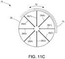
- FIG. 11Ais a perspective view of a distal tip of an application device consistent with the present disclosure illustrating a nonconductive cap member coupled to the distal tip and configured to block emission of energy from at least one of the conductive wires;
- FIG. 11Bis a front view of the distal tip of FIG. 11A illustrating energy emission from the distal tip in a specific pattern as dictated by the blockage of energy emission by the nonconductive cap member;
- FIG. 11Cis a front view of the distal tip of FIG. 11A illustrating rotational movement of the nonconductive cap member
- FIG. 12is an exploded perspective view of an ablation device consistent with the present disclosure.
- FIG. 13Ais a front view of one embodiment of a distal tip of the ablation device of FIG. 12 illustrating one or more chambers formed within the distal tip;
- FIG. 13Bis a sectional view of one embodiment of the ablation device of FIG. 12 taken along lines A-A, illustrating at least two of the chambers within the distal tip;
- FIG. 14Ais a rear view of the distal tip, in a direction from the neck towards the spheroid body, providing a view into the cavity of the distal tip and further illustrating a contractable/expandable aperture for each chamber to control passage of fluid therethrough;
- FIG. 14Billustrates an exemplary control member coupled to one of the contractable/expandable apertures and configured to control contraction/expansion of the aperture;
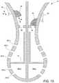
- FIG. 15is a sectional view of the ablation device of FIG. 12 illustrating a moveable plunger within each chamber and configured to move relative to the inlet port so as to allow control of passage of fluid into the inlet port and subsequent passage of fluid through one or more perforations in a chamber and to an external surface of the distal tip;
- FIGS. 16 and 17are perspective and exploded perspective views, respectively, of one embodiment of a device controller consistent with the present disclosure
- FIG. 18is an exploded perspective view of another embodiment of an ablation device consistent with the present disclosure.
- FIG. 19is a plan view of the ablation device of FIG. 18 illustrating the two halves of the device separated from one another and showing the external surface of each;
- FIG. 20is a plan view of the ablation device of FIG. 18 illustrating the two halves of the device separated from one another and showing the interior surface of each;
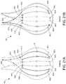
- FIGS. 21A and 21Bare enlarged views of the spheroid body of the first halve of the device showing the exterior and interior surfaces, respectively, and further illustrating the particular arrangement of first and second conductive wires extending through proximal and distal ports of the spheroid body;
- FIGS. 22A and 22Bare enlarged views of the spheroid body of the second halve of the device showing the exterior and interior surfaces, respectively, and further illustrating the particular arrangement of third and fourth conductive wires extending through proximal and distal ports of the spheroid body;
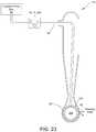
- FIG. 23is a schematic illustration of the ablation device of FIG. 18 illustrating delivery of fluid from the irrigation pump, as controlled by the controller, to the hydrophilic insert within the interior chamber of the distal portion of the device;
- FIG. 24is a perspective view of a detachable mount for holding a temperature probe (or any other separate monitoring device) at a desired position relative to the distal portion of the ablation device for the collection of temperature data during an RF ablation procedure;
- FIG. 25is a plan view of the detachable mount holding the temperature probe relative to the distal portion of the ablation device.
- the present disclosureis generally directed to a system for monitoring and controlling an ablation device to cause the ablation device to emit energy in a desired shape or pattern so as to deliver treatment for the ablation and destruction of a targeted portion of marginal tissue around the tissue cavity.
- the present disclosureis generally includes a controller configured to selectively control energy emission from an electrode array of an ablation device based on ablation feedback received during an ablation procedure with the ablation device.
- the controlleris configured to receive feedback data from one or more sensors during an ablation procedure.
- the feedback dataincludes one or more measurements associated with at least one of operation of the electrode array of the ablation device and tissue adjacent to the electrode array.
- the controlleris further configured to generate an ablation pattern for controlling energy emission from the electrode array of the ablation device in response to the received feedback data.
- the devices, systems, and methods of the present disclosurecan help to ensure that all microscopic disease in the local environment has been treated. This is especially true in the treatment of tumors that have a tendency to recur.
- the system of the present inventionallows for non-uniform ablation to occur. This is particularly useful in controlling ablation shape so as to avoid vital organs and any critical internal/external structures (e.g., bone, muscle, skin) in close proximity to the tumor site, while ensuring that residual marginal tissue within the local environment has been treated.
- body cavitymay include non-surgically created cavities, such as natural body cavities and passages, such as the ureter (e.g. for prostate treatment), the uterus (e.g. for uterine ablation or fibroid treatment), fallopian tubes (e.g. for sterilization), and the like.
- the uretere.g. for prostate treatment
- the uteruse.g. for uterine ablation or fibroid treatment
- fallopian tubese.g. for sterilization
- FIG. 1is a schematic illustration of an ablation system 10 for providing targeted ablation of marginal tissue during a tumor removal procedure in a patient 12 .
- the ablation system 10generally includes an ablation device 14 , which includes a probe having a distal tip or portion 16 and an elongated catheter shaft 17 to which the distal tip 16 is connected.
- the catheter shaft 17may generally include a nonconductive elongated member including a fluid delivery lumen.
- the ablation device 14may further be coupled to a device controller 18 and an ablation generator 20 over an electrical connection (electrical line 34 shown in FIG. 2 ), and an irrigation pump or drip 22 over a fluid connection (fluid line 38 shown in FIG. 2 ).
- the device controller 18may further include a custom ablation shaping (CAS) system 100 configured to provide a user with custom ablation shaping, which includes the creation of custom, user-defined ablation geometries or profiles from the ablation device 14 .
- CAScustom ablation shaping
- the device controller 18may be housed within the ablation device 14 .
- the ablation generator 20may also connected to a return electrode 15 that is attached to the skin of the patient 12 .
- the ablation generator 20may generally provide RF energy (e.g., electrical energy in the radiofrequency (RF) range (e.g., 350-800 kHz)) to an electrode array of the ablation device 14 , as contollered by the device controller 18 .
- RF energye.g., electrical energy in the radiofrequency (RF) range (e.g., 350-800 kHz)
- salinemay also be released from the distal tip 16 .
- the RF energytravels through the blood and tissue of the patient 12 to the return electrode 112 and, in the process, ablates the region(s) of tissues adjacent to portions of the electrode array that have been activated.
- FIG. 2is a perspective view of the distal portion or tip 16 of the ablation device 14 .
- the distal tip 16may include a neck portion 24 and a generally spheroid body 26 extending distally from the neck 24 .
- the spheroid body 26may be configured to transition between a collapsed state and an expanded state.
- the spheroid body 26may be collapsible to a delivery configuration having a reduced size (e.g., equatorial diameter) relative to the deployed configuration size (e.g., equatorial diameter) of the spheroid body 26 .
- the spheroid body 26is a generally prolate-spheroid during delivery and transitions to a spheroid shape during deployment.
- the spheroid body 26may be rigid, and thus may maintain a default shape.
- the spheroid body 26includes a non-conductive material (e.g., a polyamide) as a layer on at least a portion of an internal surface, an external surface, or both an external and internal surface.
- a non-conductive materiale.g., a polyamide
- the spheroid body 26is formed from a non-conductive material.
- the spheroid body 26 materialcan include an elastomeric material or a shape memory material.
- the spheroid body 26has a diameter (e.g., an equatorial diameter) of about 80 mm or less.
- the spheroid body 26 of the distal tipin a deployed configuration, has an equatorial diameter of 2.0 mm to 60 mm (e.g., 5 mm, 10 mm, 12 mm, 16 mm, 25 mm, 30 mm, 35 mm, 40 mm, 50 mm, and 60 mm).
- the collapsibility of the spheroid body 28can enable the distal tip to be delivered using standard sheaths (e.g., an 8 F introducer sheath).
- the distal tip 16 of the ablation device 14further includes an electrode array positioned thereon.
- the electrode arrayincludes at least one conductive member 28 .
- the electrode arrayincludes at least eight conductive members 28 .
- the electrode arraymay include a plurality of conductive members 28 .
- the plurality of conductive members 28extend within the distal tip 16 , through a channel 32 and along an external surface of the spheroid body 26 .
- the conductive members 28extend along the longitudinal length of the distal tip 16 and are radially spaced apart (e.g., equidistantly spaced apart) from each other.
- conductive memberstransmit RF energy from the ablation generator and can be formed of any suitable conductive material (e.g., a metal such as stainless steel, nitinol, or aluminum).
- the conductive members 28are metal wires. Accordingly, for ease of description, the conductive member(s) will be referred to hereinafter as “conductive wire(s) 28 ”.
- one or more of the conductive wires 28can be electrically isolated from one or more of the remaining conductive wires 28 .
- This electrical isolationenables various operation modes for the ablation device 14 .
- ablation energymay be supplied to one or more conductive wires 28 in a bipolar mode, a unipolar mode, or a combination bipolar and unipolar mode.
- unipolar modeablation energy is delivered between one or more conductive wires 28 on the ablation device 14 and the return electrode 12 , as described with reference to FIG. 1 .
- bipolar modeenergy is delivered between at least two of the conductive wires 28 , while at least one conductive wire 28 remains neutral.
- at least, one conductive wirefunctions as a grounded conductive wire (e.g., electrode) by not delivering energy over at least one conductive wire 28 .
- the electrode arraymay further include one or more stabilizing members 30 configured to provide support for the plurality of conductive wires 28 .
- the one or more stabilizing member 30generally extend along a surface (e.g., external or internal) of the distal tip 16 so as to circumscribe the spheroid body 26 .
- the stabilizing members 30can, in some examples, electrically connect to one or more conductive wires 28 .
- the stabilizing members 30are non-conductive.
- the stabilizing members 30can be formed of a suitably stiff material (e.g., metal such as stainless steel, nitinol, or aluminum).
- the stabilizing members 30can be integral with a portion of the spheroid body 26 (e.g., as a rib). While, the distal tip 16 is generally shown with one or more stabilizing members, in some implementations, the distal tip 16 is free of stabilizing members.
- the distal tip 16may be coupled to the ablation generator 20 and/or irrigation pump 22 via an electrical line 34 and a fluid line 38 , respectively.
- Each of the electrical line 34 and fluid line 38may include an adaptor end 36 , 40 configured to couple the associated lines with a respective interface on the ablation generator 20 and irrigation pump 22 .
- the ablation device 14may further include a user switch or interface 19 serving as the device controller 18 and in electrical communication with the ablation generator 20 and the ablation device 14 .
- the switch 19can provide a user with various options with respect to controlling the ablation output of the device 14 , as will be described in greater detail herein.
- the switch 19which may serve as the device controller 18 , may include a CAS system 100 configured to provide custom ablation shaping controls for a user to create custom, user-defined ablation geometries or profiles, as well as control particular ablation parameters, such as control of timing of the emission (e.g., length of time, intervals, etc.) as well as the depth of RF energy penetration.
- the switch 19may be configured to control energy delivery from the ablation generator 20 so that one or more individual conductive wires, or a designated combination of conductive wires, are energized for a pre-selected, or desired, duration.
- FIGS. 3A, 3B, and 3Care perspective views of the distal tip 16 of FIG. 2 in greater detail.
- the conductive wires 28extend through a lumen 42 within the distal tip 16 .
- each of the conductive wires 28enters the lumen 42 of the neck 27 and extends through the distal tip portion 16 before exiting the distal tip through either a center channel 32 at a distal most portion of the distal tip or one of a plurality of proximal ports 44 .
- a plurality of distal ports 46 extending through a wall of the distal tip 16is positioned around the channel 32 .
- a plurality of proximal ports 44can also extend through a wall of the distal tip 16 . These proximal ports 44 can be positioned around the distal tip 16 in close proximity (e.g., within at least 5 mm, within at least 3 mm, within at least 1 mm, within 0.5 mm, within 0.4 mm, or within 0.2 mm) to the junction between the spheroidal body 26 and the neck 24 of the distal tip 16 . In some cases, the number of proximal ports 44 and distal ports 46 is equal to the number of conductive wires 28 .
- each conductive wire 28can extend through a different distal port 46 , which allows the conductive wires 28 to remain electrically isolated from one another. In other examples, one or more conductive wires can extend through the same distal port 46 .
- each conductive wire 28can extend along an external surface of the distal tip 16 .
- the length of the conductive wire 28 extending along the external surfaceis at least 20% (e.g., at least, 50%, 60%, 75%, 85%, 90%, or 99%) of the length of the spheroid body 26 .
- the conductive wire 28can then re-enter the lumen 42 of the distal tip 16 through a corresponding proximal port 44 . For example, as shown in FIG.
- conductive wire 28 ( 1 )passes through distal port 46 ( 1 ), extends along a length of the external surface of the distal tip 16 , and passes through an associated proximal port 44 ( 1 ) into the lumen 42 of the distal tip 16 , while conductive wire 28 ( 2 ) is electrically isolated from conductive wire 28 ( 1 ) in that it passes through associated proximal and distal ports 44 ( 2 ), 46 ( 2 ), respectively.
- each conductive wire 28can extend through a different associated proximal port 44 , which allows the conductive wires 28 to remain electrically isolated from one another.
- one or more conductive wirescan extend through the same proximal port.
- an individual conductive wirecan extend through multiple proximal and distal ports.
- FIG. 4is a block diagram illustrating the custom ablation shaping (CAS) system 100 of the device controller 18 .
- the electrode arrayis composed of a plurality of conductive wires 28 electrically isolated and independent from one another. This design allows for each conductive wire 28 to receive energy in the form of electrical current from the ablation generator 20 and emit RF energy in response.
- the device controller 18is configured to selectively control the supply of electrical current to each of the conductive wires via the CAS system 100 .
- the CAS system 100includes one or more of the following: a user interface 102 ; an ablation tracking interface subsystem 104 ; an ablation mapping subsystem 106 ; an ablation geometry shaping subsystem 108 ; an electrode connection multiplier controller 110 ; and an electrode connection multiplexer controller 112 .
- the dashed connections(between the user interface 102 and electrode connection multiplier controller 110 and the electrode connection multiplexer controller 112 ) indicate fail-safes and out-of-band control lines not used, or intended for use, during normal operation. However, in the event that one or more of the components fail to operate as intended, the user may override such components so as to directly control activation of one or more conductive wires 28 .
- the specific design of the electrode arrayallows for each conductive wire to receive energy in the form of electrical current from the ablation generator 20 and emit RF energy in response.
- the device controller 18allows for individual conductive wires, or a designated combination of conductive wires, to be controlled so as to result in the activation (e.g., emission of RF energy) of corresponding portions of the electrode array.
- the device controller 18specifically by way of the CAS system 100 , provides a user with the ability to manually control the supply of electrical current to each of the conductive wires.
- the user interface 102may provide a user with the ability to create custom ablation shapes or patterns, or further manipulate ablation parameters (e.g., timing and intensity) via an interactive interface, which may be in the form of a graphical user interface (GUI) provided on a display of the device controller 18 or switch 19 .
- GUIgraphical user interface
- the CAS system 100may allow a user to manually control emission from the electrode array and customize the ablation shape or geometry as they see fit.
- the CAS system 100may be configured to automatically provide custom ablation shaping in addition, or alternatively, to manual input from a user.
- the device controller 18may be configured to provide ablation status mapping based on real-time data collection (e.g., temperature and conductivity measurements (impedance measurements) from one or more of the conductive wires) so as to provide an estimation of the state of the tissue during an RF ablation procedure.
- the CAS system 100is configured to generate ablation status mapping of a target tissue based, at least in part, on characterizing temporal changes in conductivity of a target tissue during ablation and correlating such changes with temperature and cell viability.
- the ablation status mappingmay then be combined with an electrode activation algorithm for the assignment of parameters for selective electrode activation for ablation shaping.
- the automatic custom ablation shaping feature of the present inventionallows for spatial resolution of the ablation mapping and shaping systems to occur in vitro and further determine the depths from the electrode which the mapping/sensing system can make reliable estimations.
- the systemcan compensate ablation progression during control parameter calculations so as to provide more accurate ablation of a target tissue while avoiding any vital organs or critical internal/external structures in close proximity to the target tissue.
- the CAS system 100is configured to collect data for a machine learning model and then use the model to map ablation status in real time.
- the data collectedincludes, but is not limited to, temperature measurements, conductivity or impedance measurements, and photonic properties of the target tissue.
- the CAS system 100is configured to determine the ablation shape or geometry (energy emission from electrode array) in real-, or near-real-, time.
- each conductive wire in the electrode arrayis electrically independent, each conductive wire can be connected in a fashion that allows for impedance measurements using bipolar impedance measurement circuits.
- the conductive wirescan be configured in such a fashion that tetrapolar or guarded tetrapolar electrode configurations can be used.
- one pair of conductive wirescould function as the current driver and the current return, while another pair of conductive wires could function as a voltage measurement pair.
- the dispersive ground pads 15can also function as current return and voltage references. Their placement dictate the current paths and thus having multiple references can also benefit by providing additional paths for determining the ablation status of the tissue.
- the electrode connection multiplexer controller 112is configured to collect the data in the form of local impedances (impedances between conductive wires on the distal tip) and global impedances (impedances between conductive wires and global dispersive return 15 ) and further transmit such data to the ablation mapping subsystem 106 .
- a Kelvin electrode configuration driven with 500 ⁇ A at 200 kHz (for filtering from the 470 kHz RF signal)may be used in order to measure these impedances.
- the ablation mapping subsystem 106is configured to analyze the impedance data with time elapsed in order to form a judgment of the ablation status of certain parts of the entire ablation volume.
- the ablation mapping subsystem 106may include custom, proprietary, known and/or after-developed analysis code (or instruction sets), hardware, and/or firmware that are generally well-defined and operable to receive one or more sets of data and estimate an ablation status of local target tissue sub volumes based on analysis of such data.
- the ablation mapping subsystem 106may utilize a specific input model in order to output an ablation status integer for any sub volume of the ablation volume.
- the input modelis as follows: ( t,s ,init_local_ Z [ ],init_global_ Z [ ],current_local_ Z [ ],current_global_ Z [ ] ,x,y,z ) ⁇ AblationStatus
- ‘t’indicates time in seconds
- ‘s’indicates the size of the applicator (diameter, area, volume, etc. of the distal tip)
- ‘Z’indicates impedance
- ‘H’indicates arrays with length of the number of conductive wires
- ‘x,y,z’are the coordinates of the sub volume.
- each sub volume the ablation mapmay include five possible statuses: “0” indicating no ablation occurring, “1” indicating that heating is occurring, “2” indicating that instantaneous ablation or coagulation has begun (the tissue has reached a temperature of 60° C.), “3” indicating that ablation has occurred, and “4” indicating that desiccation (vaporization) is occurring.
- benchtop ablationsare performed where the following training data is collected: time, init_local_Z[ ], init_global_Z[ ], current_local_Z[ ], current_global_Z[ ], and for a set of radii (0.25, 0.5, 0.75, 1.0, 1.25, 1.5 cm) surrounding the applicator, the exact temperature, which translates to the ablation status (0 for initial temperature, 1 for ⁇ 40° C., 2 for ⁇ 50° C., 3 for ⁇ 60° C., 4 for ⁇ 100° C.).
- This method of ablation mappingis also designed to be mostly heterogeneity-invariant, since local impedances are inputs into the model, which treat the heterogeneous tissues as different tissue types present.
- training datamay then be input into multiple supervised machine learning algorithms, where the most accurate classifier will be used for the real-time system.
- Training datamay be collected within ex vivo bovine and porcine liver blocks of 10 cm by 10 cm by 10 cm.
- the tissuecan be placed in a saline bath such that the global ground is simulated as far-field to prevent optimistic global impedance measurements. Verifications on the classifier will be performed after the model is learned to ensure success criteria, including controls with and without RF energy applied.
- the target endpointis 90% accuracy (with zero false ablated statuses) of ablation status mapping with 1.0 mm of spatial sub volume resolution for the local field ( ⁇ 1.0 cm depth from applicator surface). Additional success criteria may include the accuracy of ablation status mapping up to 3.0 mm sub volume resolution into the sub global field (1.0-2.0 cm depth from applicator surface).
- the classifierfails to classify based only on initial and changes in impedance, then an additional parameter, the estimated local tissue conductivity, will be added to the model.
- the estimated conductivityis covered within the model by the initial and early-time impedances, but a more explicit variable may be required. If the target endpoint spatial resolutions failed to be realized, then the electrodes will be increased in number to increase density for higher spatial resolution.
- the ablation geometry shaping subsystem 108is configured to receive output data from the ablation mapping subsystem 106 , specifically ablation status mapping data via the ablation tracking interface subsystem 104 , and determine a specific ablation shape or geometry to output (e.g., identify specific conductive wires or combination of conductive wires to apply power to and the specific parameters) in order to achieve the desired custom ablation shape based on the ablation status mapping.
- the ablation geometry shaping subsystem 108may rely on an electrode activation algorithm necessary to operate the network of solid-state relays (also known as a crossbar) that connect the conductive wires to the radiofrequency power generator 20 .
- the ablation geometry shaping subsystem 108may generate ablation shape data based on processing of the ablation status mapping data via the electrode activation algorithm.
- the ablation geometry shaping subsystem 108may then transmit ablation shape data to the electrode connection multiplexer controller 112 for activation of specific conductive wires, or combinations of conductive wires, so as to achieve the desired ablation shape.
- the electrode connection multiplier controller 110may be configured to physically operate solid-state relays on the electrode connection multiplexer (the electrode-switching/power-switching circuit), connecting the electrodes needed to RF power.
- PWMpulse width modulation
- Time-multiplexingmay be especially important for deeper ablations that are geometrically between multiple conductive wires, in which the theoretical circuit relies on heat transfer to nearby (i.e., not currently electrically-conducting) tissues and only the concentration of heat in the desired zone due to the combined efforts of the conductive wires activating in the multiplexed fashion.
- the ablation mapping subsystem 106 and ablation geometry shaping system 108may be configured to continuously operate during a procedure so as to provide up-to-date information which may further improve the accuracy and safety of the ablation procedure.
- ablation status mapping datamay be continuously generated and fed into the ablation geometry shaping system 108 so as to continuously generate ablation shaping data, which may be used to either validate the current ablation energy applied, or to update or correct the ablation shape (i.e., indicate where to continue ablation or when to stop ablation).
- ablation mapping statuscan be displayed to a user using a 3D visualization, which can be controlled by the user interface 102 (e.g., touchscreen or the like) similar to a 3D map application. Each layer of tissue may be displayed as being somewhat transparent so as to allow for the operator to see which regions are ablated and which are not.
- the device controller 18may be configured to be operated manually, such that a user (e.g., surgeon or operator) may input desired ablation shape or pattern and associated parameters.
- FIG. 5is a top view of one embodiment of device controller 19 configured for individually controlling operational modes of each of the plurality of conductive wires of the electrode array of the ablation device tip.
- the controller 19may provide selectable inputs 50 ( 1 )- 50 ( 8 ) in which a user may turn individual conductive wires, or one or more combinations of conductive wires, on and off, thereby allowing a user to control an ablation shape or geometry.
- the selectable inputs 50 ( 1 )- 50 ( 8 )may correspond to the eight individual conductive wires 28 ( 1 )- 28 ( 8 ) of the distal tip 16 (see FIGS. 6A-6B and 7A-7B ). Accordingly, activation of any one of the selectable inputs 50 may result in the activation of corresponding conductive wires 28 .
- FIG. 6Ais a top view of the device controller 19 with inputs 50 in a first mode
- FIG. 6Bis a front view of the ablation device tip illustrating the electrode array operating in the first mode.
- input 50 ( 1 )is selected and, in turn, the corresponding conductive wire 28 ( 1 ) is activated (current supplied thereto and RF energy emitted).
- the electrode arraymay be configured to operate in a monopolar mode in which individual conductive wires may be activated.
- FIG. 7Ais a top view of the device controller 19 with inputs 50 in a second mode and FIG. 7B is a front view of the ablation device tip illustrating the electrode array operating in the second mode.
- inputs 50 ( 1 )- 50 ( 4 )are selected and, in turn, the corresponding conductive wires 28 ( 1 )- 28 ( 4 ) are activated, such that the electrode array may operate in a bipolar mode, where pairs of conductive wires 28 ( 1 )- 28 ( 2 ) and 28 ( 3 )- 28 ( 4 ) are activated.
- FIGS. 8A-8Eare perspective views of a distal tip 16 of the ablation device of FIG. 1 illustrating various electrode array configurations.
- the conductive wires 28have been described as extending along an external surface of the distal tip 16 in a direction that is parallel to the longitudinal axis of the device (as shown in a longitudinal configuration of conductive wires 28 a in FIG. 8A ), other configurations are possible.
- one or more conductive wires 28 bcould extend along the external surface of the distal tip 16 in a direction that is perpendicular to the longitudinal axis of the device (as shown in a circumferential configuration in FIG. 8B ).
- one or more conductive wires 28 ccan extend from along the external surface of the distal tip 16 at an angle (e.g., non-parallel to the longitudinal axis of the device), as shown in an angled configuration in FIG. 8C .
- One or more conductive wires 28 d , 28 e , and 28 fcan also form a pattern along the external surface in which the conductive wires extend in various directions, as shown in a combined configuration in FIG. 8 D.
- one or more conductive wires 28 gcan extend a reduced length of the external surface an alternative configuration in FIG. 8E .
- FIG. 9is a side view of the distal tip 16 of the ablation device 14 of FIG. 1 including several clinical axes or sides. Each clinical axis or side includes one or more independently connected electrodes, which enables differential function and current independent drives and/or measurements.
- the distal tip 16can be divided into clinical axes or sides 52 , 53 , 54 , 55 , 56 , and 57 (not shown).
- the distal tip 16may include six clinical axes or sides of the distal portion (e.g, four sides or quadrants around spheroid body 54 , 55 , 56 , and 57 , and a bottom axis/side 52 , and a top axis/side 53 ).
- FIGS. 10-10Dare side and perspective views of the distal tip of the application device illustrating the different clinical axes or sides of FIG. 9 .
- each clinical axiscan include multiple independently connected conductive wires.
- clinical axis/side 52can include three independently connected conductive wires 58
- clinical axis/side 53can include three independently connected conductive wires 60
- clinical axis/side 54can include three independently controlled conductive wires 62
- clinical axis/side 55can include three independently connected conductive wires 64
- clinical axis/side 56can include three independently controlled conductive wires 66
- clinical axis/side 57can include three independently controlled conductive wires 68 .
- each clinical axis or sideallows for differential function and independent energy delivery and/or measurements. While FIGS. 10A-10D generally show three conductive wires for each clinical axis or side, other combinations are possible.
- each of the clinical axes or sidescan include a combination of conductive wires ranging from one conductive wire to ten or more conductive members.
- FIG. 11Ais a perspective view of a distal tip 16 of an application device consistent with the present disclosure illustrating a nonconductive cap member 70 coupled to the distal tip 16 and configured to block emission of energy from at least one of the conductive wires 28 .
- the nonconductive cap member 70may be selectively positionable over one or more portions of the electrode array so as to block emission of energy therefrom while permitting the emission of energy from remaining portions of the electrode array. Accordingly, the nonconductive cap member 70 allows for the ablation of a target tissue in a specific pattern, as dictated by the physical coverage of the cap member 70 .
- the cap member 70may be positioned over at least three of the eight conductive wires (covering conductive wires 28 ( 6 )- 28 ( 8 )). Thus, by blocking energy emission from wires 28 ( 6 )- 28 ( 8 ), the remaining conductive wires ( 28 ( 1 )- 28 ( 5 ) remain able to emit energy in a particular ablation shape or geometry. Accordingly, the nonconductive cap member 70 may be selectively positionable over one or more of the plurality of conductive wires so as to block emission of energy from such wires and preventing emission from the corresponding portion of the electrode array, while permitting the remaining wires to emit energy. As illustrated in FIG.
- the cap member 70is configured to be selectively positionable relative to the conductive wires 28 .
- the cap member 70may be rotationally coupled to the distal tip 16 , such that a user may simply use a controller, or other means, for rotating the cap member 70 about the spheroid body 26 , as indicated by arrow 72 , so as to manually cover a specific wires 28 so as to select a desired ablation shape or geometry.
- the nonconductive cap member 70may have a predefined shaped or size, such that the cap member 70 has a fixed area of coverage (e.g., is limited covering a specific number of conductive wires or number of electrode array portions).
- the cap member 70may be shaped or sized to cover a single quadrant of a spheroid distal portion, such that, at any given time, three out of four quadrants will remain uncovered and thus emit RF energy in a corresponding pattern.
- the nonconductive cap member 70may be shaped or sized to cover more than one quadrant (e.g., at least two quadrants, at least three quadrants, etc.).
- FIG. 12is an exploded perspective view of an ablation device 14 consistent with the present disclosure.
- the ablation device 14specifically the distal tip 16 , may be formed from two or more pieces (tip halves 16 a and 16 b ) configured to be coupled to one another to form the unitary distal tip 16 .
- Each half 16 a and 16 bincludes cooperating neck portions 24 a , 24 b and spheroid bodies 26 a , 26 b , as well as a cap 76 to be coupled to both halves 16 a and 16 b so as to fully enclose the interior of the distal tip 16 .
- an electrical line 34may be provided for coupling the conductive wires 28 to the controller 18 and ablation generator 20 and a fluid line 38 may be provided for providing a fluid connection between the irrigation pump or drip 22 to the distal tip 16 so as to provide a conductive fluid (e.g., saline) to the tip 16 .
- the electrical line 34 and/or the fluid delivery line 38can be supported by a stabilizing element 84 within the device lumen. In some cases, the stabilizing element 84 may be integral with the neck 24 of the distal tip 16 .
- conductive members 28extend through a first port (e.g., the distal port 44 ), run along an external surface of the spheroid body 26 (e.g. within the groove 74 ) before re-entering the lumen of the distal tip 16 through another port (e.g., the proximal port 46 ).
- a conductive fluidsuch as saline, may be provided to the distal tip 16 via the fluid line 38 , wherein the saline may be distributed through the ports (e.g., to the distal ports 44 , the proximal ports 46 , and/or medial ports 45 ).
- the saline weeping through the ports and to an outer surface of the distal tip 16is able to carry electrical current from electrode array, such that energy is transmitted from the electrode array to the tissue by way of the saline weeping from the ports, thereby creating a virtual electrode. Accordingly, upon the fluid weeping through the ports, a pool or thin film of fluid is formed on the exterior surface of the distal tip 16 and is configured to ablate surrounding tissue via the electrical current carried from the electrode array.
- FIG. 13Ais a front view of one embodiment of a distal tip 16 of the ablation device 14 of FIG. 12 illustrating one or more chambers formed within the distal tip 16 and FIG. 13B is a sectional view of distal tip 16 taken along lines A-A.
- the distal tip 16may include at least two internal chambers configured to receive and retain fluid therein as provided by the fluid line 38 .
- the distal tip 16is partioned into quadrants such that it includes four separate chambers 86 ( 1 )- 86 ( 4 ).
- FIG. 13Billustrates at least two of the internal chambers 86 ( 3 ) and 86 ( 4 ).
- each chamber 86generally includes an inlet port 88 configured to receive the fluid from the fluid delivery line 38 and further allow the fluid to flow into the corresponding chamber 86 .
- Each chamber 86further includes one or more perforations in a wall of the chamber. As shown in FIG. 13B , the one or more perforations may include ports 44 - 46 . However, in some embodiments, each chamber may include additional perforations (such as perforations 98 shown in FIG. 15 ).
- the ports, or perforationsmay generally be configured to allow fluid to pass therethrough, or weep, from the chamber 86 to an external surface of the spheroid body 26 .
- the ablation devicefurther includes an electrode array positioned along an external surface of the distal portion.
- the electrode arraycan be activated.
- the fluid weeping through the perforations of the internal chambers and to the outer surface of the spheroid body of the distal portionis a conductive fluid (e.g., saline) and thus able to carry electrical current from electrode array, such that energy is transmitted from the electrode array to the tissue by way of the fluid weeping from the perforations, thereby creating a virtual electrode.
- a conductive fluide.g., saline
- the ablation device 14may further include includes at least one flow control member associated with each chamber 86 so as to modify fluid flow into or out of each chamber 86 by way of a user manipulating a controller 90 .
- the at least one flow control memberis configured to transition between open, closed, and intermediate positions so as to ultimately control the passage of fluid through the one or more perforations to the external surface of the spheroid body, thereby effectively controlling the ablation pattern or shape.
- a flow control member associated with a first internal chamberis completely closed, thereby preventing flow of fluid through the perforations of the first internal chamber, ablation is prevented from occurring along an external surface of the spheroid body associated with the first internal chamber.
- the flow control membermay include a contractable/expandable aperture 92 essentially serving as the inlet port for each chamber 86 .
- FIG. 14Ais a rear view of the distal tip 16 , in a direction from the neck 24 towards the spheroid body 26 , providing a view into the lumen 42 of the distal tip 16 .
- each internal chamber 86 ( 1 )- 86 ( 4 )has an associated contractable/expandable aperture 92 ( 1 )- 92 ( 4 ) configured to control the flow rate of fluid into the associated chamber 86 so as to modify fluid flow out of the ports or perforations of the chamber 86 .
- the contractable/expandable apertures 92 ( 1 )- 92 ( 4 )may generally resemble a lens iris (commonly found in cameras) configured to transition between fully open, fully closed, and intermediate positions there between.
- FIG. 14Billustrates an exemplary control member 90 coupled to a contractable/expandable aperture 92 and configured to control contraction/expansion of the aperture 92 .
- a usermay be able to manipulate the control member 90 so as to transition the aperture 92 between fully open and fully closed positions.
- Each aperture 92may include an associated control member 90 , such that a user may be able to independently control the contract/expansion of the individual apertures 92 separately from one another to customize the ablation shape or geometry.
- the flow control membermay include a moveable plunger 94 positioned within each chamber 86 and configured to move relative to the inlet port 88 so as to control of the passage of fluid into the inlet port and subsequently control weeping of fluid through the ports or perforations.
- each plunger 94may be coupled a control member 90 (e.g., button, switch, etc.) configured to move in a direction relative to the inlet port 88 , as indicated by arrow 96 .
- a usermay manipulate the control member 90 to move the plunger between a fully open position, as shown with respect to the inlet port of chamber 86 ( 4 ), and a fully closed position, in which the plunger 94 is engaged with the inlet port 88 , as shown with respect to chamber 86 ( 3 ), so as to prevent fluid flow into the 86 ( 3 ), thus modifying flow passage through the perforations 98 .
- Each of the internal chambers 86may further include a ledge or shelf 97 provided therein, wherein the ledge 97 is positioned so as to improve uniformity of fluid distribution to one or more of the perforations, most notably the perforations most proximate to the neck 24 (e.g., perforations 98 ( 1 )- 98 ( 3 ).
- fluid within a chamber 86may have the tendency to pool near a bottom of the chamber 86 depending on the orientation of the spheroid body 26 due to gravity.
- those perforations that are closest to the neck 24will likely not receive fluid to pass therethrough, which may lead to inaccurate or incomplete ablation, as the fluid is not evenly distributed along the external surface of the body 26 .
- the ledge 97is positioned in such a manner that fluid may first accumulate within a portion of the ledge 97 and allow the perforations 98 ( 1 )- 98 ( 3 ) to fill with fluid prior to the remaining perforations 98 ( 4 ) and 98 ( 5 ), which will normally fill with fluid, thereby ensuring uniform distribution of fluid weeping.
- FIGS. 16 and 17are perspective and exploded perspective views, respectively, of another one embodiment of a device controller 200 consistent with the present disclosure. Similar to user switch or interface 19 , the device controller 200 may serve as the device controller 18 and is in electrical communication with the ablation generator 20 as well as the irrigation pump/drip 22 . Accordingly, the controller 200 can provide a user with various options with respect to controlling the ablation output of an ablation device consistent with the present disclosure, specifically providing a surgeon with the functions provided by switch 19 and/or the controller 18 having control of the CAS system 100 .
- controller 200may include the CAS system 100 configured to provide custom ablation shaping controls for a user to create custom, user-defined ablation geometries or profiles, as well as control particular ablation parameters, such as control of timing of the emission (e.g., length of time, intervals, etc.) as well as the depth of RF energy penetration.
- control particular ablation parameterssuch as control of timing of the emission (e.g., length of time, intervals, etc.) as well as the depth of RF energy penetration.
- the controller 200may include a first halve or shell 202 a and a second halve or shell 202 b for housing a PC 204 within, the PC board 204 comprising circuitry and hardware for controlling various parameters of the device 14 during an ablation procedure.
- the controller 200further includes a display 206 , such as an LCD or LED display for providing a visual representation of one or more parameters associated with the device 14 , including, but not limited to, device status (e.g., power on/off, ablation on/off, fluid delivery on/off) as well as one or more parameters associated with the RF ablation (e.g., energy output, elapsed time, timer, temperature, conductivity, etc.).
- the controller 200may further include a top membrane 208 affixed over the PC board 204 and configured to provide user input (by way of buttons or other controls) with which a user (e.g., surgeon or medical professional) may interact with a user interface provided on the display 206 .
- the controller 200may be configured to control at least the amount of electrical current applied to one or more of the conductive wires 28 from the ablation generator 20 and the amount of fluid to be delivered to the device 14 from the irrigation pump/drip 22 .
- FIG. 18is an exploded perspective view of another embodiment of an ablation device 14 a consistent with the present disclosure.
- the device 14 ais similarly configured as device 14 illustrated in FIG. 12 , and includes similar elements.
- the device 14 aincludes the distal tip 16 formed from two or more pieces (tip halves 16 a and 16 b ) configured to be coupled to one another to form the unitary distal tip 16 .
- Each half 16 a and 16 bincludes cooperating neck portions 24 a , 24 b and spheroid bodies 26 a , 26 b , as well as a cap 76 to be coupled to both halves 16 a and 16 b so as to fully enclose the interior of the distal tip 16 .
- an electrical line 34may be provided for coupling the conductive wires 28 to the controller 18 (or controller 200 ) and ablation generator 20 and a fluid line 38 may be provided for providing a fluid connection between the irrigation pump or drip 22 to the distal tip 16 so as to provide a conductive fluid (e.g., saline) to the tip 16 .
- a conductive fluide.g., saline
- the device 14 ais configured to provide RF ablation via a virtual electrode arrangement, which includes distribution of a fluid along an exterior surface of the distal tip 16 and, upon activation of the electrode array, the fluid may carry, or otherwise promote, energy emitted from the electrode array to the surrounding tissue.
- the nonconductive spheroid body 26includes an interior chamber (when the first and second halves 26 a , 26 b are coupled to one another) for retaining at least a spacing member 300 (also referred to herein as “spacer ball”) and one or more hydrophilic inserts 302 a , 302 b surrounding the spacing member 300 .
- the interior chamber of the distal tip 16is configured to receive and retain a fluid (e.g., saline) therein from a fluid source.
- the hydrophilic inserts 302 a , 302 bare configured receive and evenly distribute the fluid through the distal tip 16 by wicking the saline against gravity.
- the hydrophilic inserts 302 a and 302 bcan be formed from a hydrophilic foam material (e.g., hydrophilic polyurethane).
- the distal tip 16may generally include a plurality of ports or apertures configured to allow the fluid to pass therethrough, or weep, from the interior chamber to an external surface of the distal tip 16 . Accordingly, in some embodiments, all of the ports (e.g., proximal ports 44 , medial ports 45 , and distal ports 46 ) may be configured to allow for passage of fluid from the inserts 302 a , 302 b to the exterior surface of the distal tip 16 . However, in some embodiments, only the medial ports 45 may allow for fluid passage, while the proximal and distal ports 44 , 46 may be blocked via a heat shrink or other occlusive material.
- the spacer member 300may formed from a nonconductive material and may be shaped and sized so as to maintain the hydrophilic inserts 302 a , 302 b in sufficient contact with the interior surface of the distal tip wall, and specifically in contact with the one or more ports, such that the hydrophilic inserts 302 a , 302 b provides uniformity of saline distribution to the ports.
- the spacer member 300may have a generally spherical body, corresponding to the interior contour of the chamber of the spheroid body 26 .
- the electrode arraycan be activated and fluid delivery can be initiated.
- the fluid weeping through the ports to the exterior surface of the distal tipis able to carry energy from electrode array, thereby creating a virtual electrode.
- a pool or thin film of fluidis formed on the exterior surface of the distal portion and is configured to ablate surrounding tissue via the RF energy carried from the electrode array.
- conductive wires 28may generally extend through a first port (e.g., the distal port 44 ), run along an external surface of the spheroid body 26 before re-entering the lumen of the distal tip 16 through another port (e.g., the proximal port 46 ).
- FIGS. 19, 20, 21A-21B, and 22A-22Billustrate another arrangement of conductive wires 28 , in which at least four different conductive wires are provided, two of which serve as supply electrodes and the other two serve as return electrodes. Each of the four different conductive wires generally pass through at least two different proximal ports and two different distal ports, while remaining isolated from one another.
- FIG. 19is a plan view of the ablation device 14 a illustrating the two halves of the device tip 16 a , 16 b separated from one another and showing the external surface each, while FIG. 20 shows the interior surface of each.
- FIGS. 21A and 21Bare enlarged views of the spheroid body of the first halve 16 a of the device 14 a showing the exterior and interior surfaces, respectively, and further illustrating the particular arrangement of first and second conductive wires 28 ( 1 ) and 28 ( 2 ), partly in phantom, extending through proximal and distal ports 44 , 46 of the spheroid body 26 a .
- the following description of the first and second conductive wires 28 ( 1 ) and 28 ( 2 )provides a general pathway of each wire, including passages through ports and extensions along lengths of the interior and exterior surfaces of the tip 16 .
- a first conductive wire 28 ( 1 )may serve as a return electrode while a second conductive wire 28 ( 2 ) may serve as a supply electrode.
- the first conductive wire 28 ( 1 )extends within the lumen of the tip 16 a and passes through proximal port 44 ( 1 ), extends along the exterior surface of the spheroid body 26 a towards the distal ports (generally parallel to longitudinal axis of device), passes through distal port 46 ( 1 ), extends along the interior surface of the body 26 a towards adjacent distal ports (generally transverse to longitudinal axis of the device), passes through distal port 46 ( 2 ), extends along the exterior surface of the spheroid body 26 a back towards the proximal ports, passes through proximal port 44 ( 2 ), extends along the interior surface of body 26 a towards adjacent proximal ports, passes through proximal port 44 ( 5 ), extends along the exterior surface of the spheroid body 26 a back towards the distal ports, passes through distal port 46 ( 5 ), extends along the interior surface of the body 26 a towards adjacent distal ports, passes through distal port 46 ( 6 ), extend
- the second conductive wire 28 ( 2 )extends within the lumen of the tip 16 a and passes through distal port 44 ( 3 ), extends along the exterior surface of the spheroid body 26 a towards the distal ports (generally parallel to longitudinal axis of device), passes through distal port 46 ( 3 ), extends along the interior surface of the body 26 a towards adjacent distal ports (generally transverse to longitudinal axis of the device), passes through distal port 46 ( 4 ), extends along the exterior surface of the spheroid body 26 a back towards the proximal ports, passes through proximal port 44 ( 4 ), and extends back through lumen of the tip 16 a .
- the second conductive wire 28 ( 2 )has at least two portions that extend along the exterior surface of the spheroid body 26 a.
- FIGS. 22A and 22Bare enlarged views of the spheroid body of the second halve 16 b of the device 14 a showing the exterior and interior surfaces, respectively, and further illustrating the particular arrangement of third and fourth conductive wires 28 ( 3 ) and 28 ( 4 ) extending through proximal and distal ports of the spheroid body 26 b .
- the following description of the third and fourth conductive wires 28 ( 3 ) and 28 ( 4 )provides a general pathway of each wire, including passages through ports and extensions along lengths of the interior and exterior surfaces of the tip 16 .
- a third conductive wire 28 ( 3 )may serve as a return electrode while a second conductive wire 28 ( 4 ) may serve as a supply electrode.
- the third conductive wire 28 ( 3 )extends within the lumen of the tip 16 a and passes through proximal port 44 ( 9 ), extends along the exterior surface of the spheroid body 26 b towards the distal ports (generally parallel to longitudinal axis of device), passes through distal port 46 ( 9 ), extends along the interior surface of the body 26 b towards adjacent distal ports (generally transverse to longitudinal axis of the device), passes through distal port 46 ( 10 ), extends along the exterior surface of the spheroid body 26 b back towards the proximal ports, passes through proximal port 44 ( 10 ), and extends back through lumen of the tip 16 a .
- the third conductive wire 28 ( 3 )has at least two portions that extend along the exterior surface of the spheroid body 26 b.
- the fourth conductive wire 28 ( 4 )extends within the lumen of the tip 16 b and passes through proximal port 44 ( 7 ), extends along the exterior surface of the spheroid body 26 b towards the distal ports (generally parallel to longitudinal axis of device), passes through distal port 46 ( 7 ), extends along the interior surface of the body 26 b towards adjacent distal ports (generally transverse to longitudinal axis of the device), passes through distal port 46 ( 8 ), extends along the exterior surface of the spheroid body 26 b back towards the proximal ports, passes through proximal port 44 ( 8 ), extends along the interior surface of body 26 b towards adjacent proximal ports, passes through proximal port 44 ( 11 ), extends along the exterior surface of the spheroid body 26 b back towards the distal ports, passes through distal port 46 ( 11 ), extends along the interior surface of the body 26 b towards adjacent distal ports, passes through distal port 46 ( 12 ), extends along
- each of the four conductive wires 28 ( 1 )- 28 ( 4 )remain electrically isolated and independent from one another such that, each, or one or more sets of a combination of, the conductive wires, can independently receive an electrical current from the ablation generator and independently conduct energy, the energy including RF energy.
- Thisallows energy to be selectively delivered to a designated conductive wire or combination of conductive wires.
- This designalso enables the ablation device to function in a bipolar mode because a first conductive wire (or combination of conductive wires) can deliver energy to the surrounding tissue through its electrical connection with an ablation generator while a second conductive wire (or combination of conductive wire(s) can function as a ground or neutral conductive member.
- each wire or sets of wiresallows for activation (e.g., emission of RF energy) of corresponding portions of the electrode array.
- the electrode arraymay be partitioned into specific portions which may correspond to clinical axes or sides of the distal portion of the device.
- the electrode arraymay include at least four distinct portions (i.e., individual or sets of conductive wires) corresponding to four clinical axes or sides of the distal portion (e.g, four sides or quadrants around spheroid body).
- FIG. 23is a schematic illustration of the ablation device 14 a illustrating delivery of fluid from the irrigation pump 22 , as controlled by the controller 19 , to the hydrophilic inserts 302 a , 302 b within the interior chamber of the distal tip 16 , wherein the fluid can be subsequently distributed to an exterior surface of the spheroid body 26 resulting in a virtual electrode arrangement upon activation of one or more portions of the electrode array.
- the salinemay be distributed through at least the medial ports 45 , such that the weeping saline is able to carry electrical current from electrode array, such that energy is transmitted from the electrode array to the tissue by way of the saline weeping from the ports, thereby creating a virtual electrode.
- a pool or thin film of fluidis formed on the exterior surface of the spheroid body 26 and is configured to ablate surrounding tissue via the electrical current carried from the electrode array.
- FIGS. 24 and 25are perspective and plan views of a detachable mount 400 for holding and maintaining a temperature probe 402 (or any other separate monitoring device) at a desired position, as indicated by arrow 406 , relative to the spheroid body 26 of the distal tip of the ablation device 14 .
- the mount 400allows for an operator (e.g., surgeon) to releasably couple a temperature probe 402 , or other measurement device, to the ablation device 14 a and further position the working end 404 of the probe 402 in close proximity to the spheroid body 2 for the collection of temperature data during an RF ablation procedure.
- the controller 18(as well as 19 or 200 ) may be configured to provide a surgeon with the ability to control ablation, such as controlling the supply of power to one or more conductive wires as well as control the delivery of fluid to the device tip 16 .
- the controller 18may provide device status (e.g., power on/off, ablation on/off, fluid delivery on/off) as well as one or more parameters associated with the RF ablation (e.g., energy output, elapsed time, timer, temperature, conductivity, etc.).
- the mount 400is configured to provide a surgeon with the ability to adjacent the angle at which the temperature probe is positioned relative to the device tip 16 as well as the distance from the device tip 16 , thereby overcoming the drawbacks of integrated thermocouples.
- the mount 400generally includes a body having a first end 408 configured to be releasably coupled to at least the proximal end of the device 14 by way of a clamping mechanism or latch-type engagement.
- the first end 408includes a top guard member 410 configured to partially enclose at least the proximal end of the device 14 , to further enhance securement of the mount 400 to the device 14 .
- the mount 400further includes an arm member 412 extending from the first end 408 and providing a second end 414 positioned a distance from the first end 408 .
- the second end 414is configured to hold the temperature probe 402 at a desired position, including a desired distance from the spheroid body 26 and a desired angle ⁇ relative to the longitudinal axis of the ablation device.
- the second end 414may include a bore or channel configured to receive and retain a portion of the temperature probe 402 within.
- the second end 414may further allow for the temperature probe 402 to translate along the bore or channel, as indicated by arrow 416 , to thereby adjust the distance of the temperature probe tip 404 relative to the spheroid body of the device tip.
- the arm 412 and/or second end 414may articulate relative to one another and/or the first end 408 . Accordingly, the angle of the temperature probe 402 may also be adjusted as desired.
- the system of the present inventionis configured to provide a user with multiple features allowing custom ablation shaping, which includes the creation of custom, user-defined ablation geometries depending on the target site.
- custom ablation shapingwhich includes the creation of custom, user-defined ablation geometries depending on the target site.
- the systemallows for a user to customize the emission of energy to a targeted portion of marginal tissue within the cavity, which is particularly useful in instances in which non-uniform ablation is desired.
- the customized emission of energymay include a specific shape or geometry of emission, as well as time and depth of penetration of RF energy.
- the devices, systems, and methods of the present disclosurecan help to ensure that all microscopic disease in the local environment has been treated. This is especially true in the treatment of tumors that have a tendency to recur.
- the system of the present inventionallows for non-uniform ablation to occur. This is particularly useful in controlling ablation shape so as to avoid vital organs and any critical internal/external structures (e.g., bone, muscle, skin) in close proximity to the tumor site, while ensuring that residual marginal tissue within the local environment has been treated.
- controllermay refer to software, firmware and/or circuitry configured to perform any of the aforementioned operations.
- Softwaremay be embodied as a software package, code, instructions, instruction sets and/or data recorded on non-transitory computer readable storage medium.
- Firmwaremay be embodied as code, instructions or instruction sets and/or data that are hard-coded (e.g., nonvolatile) in memory devices.
- Circuitrymay comprise, for example, singly or in any combination, hardwired circuitry, programmable circuitry such as computer processors comprising one or more individual instruction processing cores, state machine circuitry, and/or firmware that stores instructions executed by programmable circuitry.
- the controller or subsystemmay, collectively or individually, be embodied as circuitry that forms part of a larger system, for example, an integrated circuit (IC), system on-chip (SoC), desktop computers, laptop computers, tablet computers, servers, smart phones, etc.
- ICintegrated circuit
- SoCsystem on-chip
- any of the operations described hereinmay be implemented in a system that includes one or more storage mediums having stored thereon, individually or in combination, instructions that when executed by one or more processors perform the methods.
- the processormay include, for example, a server CPU, a mobile device CPU, and/or other programmable circuitry.
- the storage mediummay include any type of tangible medium, for example, any type of disk including hard disks, floppy disks, optical disks, compact disk read-only memories (CD-ROMs), compact disk rewritables (CD-RWs), and magneto-optical disks, semiconductor devices such as read-only memories (ROMs), random access memories (RAMs) such as dynamic and static RAMs, erasable programmable read-only memories (EPROMs), electrically erasable programmable read-only memories (EEPROMs), flash memories, Solid State Disks (SSDs), magnetic or optical cards, or any type of media suitable for storing electronic instructions.
- Other embodimentsmay be implemented as software modules executed by a programmable control device.
- the storage mediummay be non-transitory.
- various embodimentsmay be implemented using hardware elements, software elements, or any combination thereof.
- hardware elementsmay include processors, microprocessors, circuits, circuit elements (e.g., transistors, resistors, capacitors, inductors, and so forth), integrated circuits, application specific integrated circuits (ASIC), programmable logic devices (PLD), digital signal processors (DSP), field programmable gate array (FPGA), logic gates, registers, semiconductor device, chips, microchips, chip sets, and so forth.
Landscapes
- Health & Medical Sciences (AREA)
- Surgery (AREA)
- Life Sciences & Earth Sciences (AREA)
- Engineering & Computer Science (AREA)
- Veterinary Medicine (AREA)
- General Health & Medical Sciences (AREA)
- Nuclear Medicine, Radiotherapy & Molecular Imaging (AREA)
- Public Health (AREA)
- Biomedical Technology (AREA)
- Heart & Thoracic Surgery (AREA)
- Medical Informatics (AREA)
- Molecular Biology (AREA)
- Animal Behavior & Ethology (AREA)
- Otolaryngology (AREA)
- Plasma & Fusion (AREA)
- Physics & Mathematics (AREA)
- Oral & Maxillofacial Surgery (AREA)
- Pathology (AREA)
- Neurology (AREA)
- Neurosurgery (AREA)
- Cardiology (AREA)
- Surgical Instruments (AREA)
Abstract
Description
(t,s,init_local_Z[ ],init_global_Z[ ],current_local_Z[ ],current_global_Z[ ],x,y,z)→AblationStatus
Claims (12)
Priority Applications (1)
| Application Number | Priority Date | Filing Date | Title |
|---|---|---|---|
| US15/419,256US10864039B2 (en) | 2016-02-02 | 2017-01-30 | Cavitary tissue ablation system |
Applications Claiming Priority (2)
| Application Number | Priority Date | Filing Date | Title |
|---|---|---|---|
| US201662290108P | 2016-02-02 | 2016-02-02 | |
| US15/419,256US10864039B2 (en) | 2016-02-02 | 2017-01-30 | Cavitary tissue ablation system |
Publications (2)
| Publication Number | Publication Date |
|---|---|
| US20170215951A1 US20170215951A1 (en) | 2017-08-03 |
| US10864039B2true US10864039B2 (en) | 2020-12-15 |
Family
ID=59385191
Family Applications (2)
| Application Number | Title | Priority Date | Filing Date |
|---|---|---|---|
| US15/419,269AbandonedUS20170215947A1 (en) | 2016-02-02 | 2017-01-30 | Cavitary tissue ablation system |
| US15/419,256Active2039-06-29US10864039B2 (en) | 2016-02-02 | 2017-01-30 | Cavitary tissue ablation system |
Family Applications Before (1)
| Application Number | Title | Priority Date | Filing Date |
|---|---|---|---|
| US15/419,269AbandonedUS20170215947A1 (en) | 2016-02-02 | 2017-01-30 | Cavitary tissue ablation system |
Country Status (4)
| Country | Link |
|---|---|
| US (2) | US20170215947A1 (en) |
| EP (1) | EP3410972B1 (en) |
| JP (1) | JP6630836B2 (en) |
| WO (2) | WO2017136261A1 (en) |
Families Citing this family (23)
| Publication number | Priority date | Publication date | Assignee | Title |
|---|---|---|---|---|
| US8906011B2 (en) | 2007-11-16 | 2014-12-09 | Kardium Inc. | Medical device for use in bodily lumens, for example an atrium |
| US11259867B2 (en) | 2011-01-21 | 2022-03-01 | Kardium Inc. | High-density electrode-based medical device system |
| US9452016B2 (en) | 2011-01-21 | 2016-09-27 | Kardium Inc. | Catheter system |
| US9480525B2 (en) | 2011-01-21 | 2016-11-01 | Kardium, Inc. | High-density electrode-based medical device system |
| CA2764494A1 (en) | 2011-01-21 | 2012-07-21 | Kardium Inc. | Enhanced medical device for use in bodily cavities, for example an atrium |
| ES2768107T3 (en) | 2015-04-29 | 2020-06-19 | Innoblative Designs Inc | Cavity tissue removal |
| US12207863B2 (en) | 2015-10-29 | 2025-01-28 | Innoblative Designs, Inc. | Screen sphere tissue ablation devices and methods |
| JP6933857B2 (en) | 2015-10-29 | 2021-09-08 | イノブレイティブ デザインズ, インコーポレイテッド | Net spherical tissue ablation device and method |
| WO2017136261A1 (en) | 2016-02-02 | 2017-08-10 | Innoblative Designs, Inc. | Cavitary tissue ablation system |
| WO2017151431A1 (en) | 2016-03-01 | 2017-09-08 | Innoblative Designs, Inc. | Resecting and coagulating tissue |
| WO2018075389A1 (en)* | 2016-10-17 | 2018-04-26 | Innoblative Designs, Inc. | Treatment devices and methods |
| JP6875757B2 (en) | 2016-11-08 | 2021-05-26 | イノブレイティブ デザインズ, インコーポレイテッド | Electrosurgical tissue and vascular seal device |
| JP6946444B2 (en)* | 2017-02-10 | 2021-10-06 | セント・ジュード・メディカル,カーディオロジー・ディヴィジョン,インコーポレイテッド | Equipment and methods for cryoablation |
| CN110325137A (en)* | 2017-02-23 | 2019-10-11 | 尹诺伯拉狄夫设计公司 | System and method for melting Stateful Inspection and custom ablated forming |
| EP3658053B1 (en) | 2017-07-26 | 2023-09-13 | Innoblative Designs, Inc. | Minimally invasive articulating assembly having ablation capabilities |
| US11896312B2 (en) | 2018-02-05 | 2024-02-13 | Broncus Medical Inc. | Image-guided lung tumor planning and ablation system |
| EP3813936A4 (en)* | 2018-06-06 | 2022-03-09 | Robert F. Rioux | PORTABLE WOUND TREATMENT SYSTEM |
| US20220313347A1 (en)* | 2019-05-20 | 2022-10-06 | Innoblative Designs, Inc. | Tissue ablation devices and methods |
| US12042216B2 (en)* | 2019-12-09 | 2024-07-23 | Biosense Webster (Israel) Ltd. | Irreversible-electroporation (IRE) balloon catheter with membrane-insulated high-voltage balloon wires |
| US11006902B1 (en)* | 2019-12-23 | 2021-05-18 | Biosense Webster (Israel) Ltd. | GUI for selective operation of multi-electrode catheters |
| USD1096819S1 (en) | 2019-12-23 | 2025-10-07 | Biosense Webster (Israel) Ltd. | Display screen with graphical user interface |
| US20220192742A1 (en)* | 2020-12-22 | 2022-06-23 | Biosense Webster (Israel) Ltd. | Bipolar ablation graphical user interface |
| JP2024531509A (en)* | 2021-08-31 | 2024-08-29 | イノブレイティブ デザインズ, インコーポレイテッド | Omental Tissue Ablation Device and Method - Patent application |
Citations (193)
| Publication number | Priority date | Publication date | Assignee | Title |
|---|---|---|---|---|
| US4699147A (en) | 1985-09-25 | 1987-10-13 | Cordis Corporation | Intraventricular multielectrode cardial mapping probe and method for using same |
| US4976711A (en) | 1989-04-13 | 1990-12-11 | Everest Medical Corporation | Ablation catheter with selectively deployable electrodes |
| US4979948A (en) | 1989-04-13 | 1990-12-25 | Purdue Research Foundation | Method and apparatus for thermally destroying a layer of an organ |
| US5045056A (en) | 1989-09-15 | 1991-09-03 | Behl Robert S | Method and device for thermal ablation of hollow body organs |
| US5100423A (en) | 1990-08-21 | 1992-03-31 | Medical Engineering & Development Institute, Inc. | Ablation catheter |
| US5117828A (en) | 1989-09-25 | 1992-06-02 | Arzco Medical Electronics, Inc. | Expandable esophageal catheter |
| US5334193A (en) | 1992-11-13 | 1994-08-02 | American Cardiac Ablation Co., Inc. | Fluid cooled ablation catheter |
| WO1995010326A1 (en) | 1993-10-14 | 1995-04-20 | Vesta Medical, Inc. | Bipolar/monopolar endometrial ablation device and method |
| US5429605A (en) | 1994-01-26 | 1995-07-04 | Target Therapeutics, Inc. | Microballoon catheter |
| US5471982A (en) | 1992-09-29 | 1995-12-05 | Ep Technologies, Inc. | Cardiac mapping and ablation systems |
| US5472441A (en) | 1993-11-08 | 1995-12-05 | Zomed International | Device for treating cancer and non-malignant tumors and methods |
| US5486161A (en) | 1993-02-02 | 1996-01-23 | Zomed International | Medical probe device and method |
| US5536267A (en) | 1993-11-08 | 1996-07-16 | Zomed International | Multiple electrode ablation apparatus |
| US5657760A (en) | 1994-05-03 | 1997-08-19 | Board Of Regents, The University Of Texas System | Apparatus and method for noninvasive doppler ultrasound-guided real-time control of tissue damage in thermal therapy |
| US5672153A (en) | 1992-08-12 | 1997-09-30 | Vidamed, Inc. | Medical probe device and method |
| US5672174A (en) | 1995-08-15 | 1997-09-30 | Rita Medical Systems, Inc. | Multiple antenna ablation apparatus and method |
| US5672173A (en) | 1995-08-15 | 1997-09-30 | Rita Medical Systems, Inc. | Multiple antenna ablation apparatus and method |
| US5683384A (en) | 1993-11-08 | 1997-11-04 | Zomed | Multiple antenna ablation apparatus |
| US5713942A (en) | 1992-05-01 | 1998-02-03 | Vesta Medical, Inc. | Body cavity ablation apparatus and model |
| US5728143A (en) | 1995-08-15 | 1998-03-17 | Rita Medical Systems, Inc. | Multiple antenna ablation apparatus and method |
| US5772590A (en) | 1992-06-30 | 1998-06-30 | Cordis Webster, Inc. | Cardiovascular catheter with laterally stable basket-shaped electrode array with puller wire |
| US5782827A (en) | 1995-08-15 | 1998-07-21 | Rita Medical Systems, Inc. | Multiple antenna ablation apparatus and method with multiple sensor feedback |
| US5827276A (en) | 1995-03-24 | 1998-10-27 | Board Of Regents Of Univ Of Nebraksa | Apparatus for volumetric tissue ablation |
| US5840076A (en) | 1996-04-12 | 1998-11-24 | Ep Technologies, Inc. | Tissue heating and ablation systems and methods using electrode structures with distally oriented porous regions |
| US5846239A (en) | 1996-04-12 | 1998-12-08 | Ep Technologies, Inc. | Tissue heating and ablation systems and methods using segmented porous electrode structures |
| US5863290A (en) | 1995-08-15 | 1999-01-26 | Rita Medical Systems | Multiple antenna ablation apparatus and method |
| US5868776A (en) | 1996-09-03 | 1999-02-09 | Ideas For Medicine, Inc. | Overlay dual balloon catheter and method for use thereof |
| US5868736A (en) | 1996-04-12 | 1999-02-09 | Ep Technologies, Inc. | Systems and methods to control tissue heating or ablation with porous electrode structures |
| US5871483A (en) | 1996-01-19 | 1999-02-16 | Ep Technologies, Inc. | Folding electrode structures |
| US5888198A (en) | 1992-01-07 | 1999-03-30 | Arthrocare Corporation | Electrosurgical system for resection and ablation of tissue in electrically conductive fluids |
| US5891136A (en) | 1996-01-19 | 1999-04-06 | Ep Technologies, Inc. | Expandable-collapsible mesh electrode structures |
| US5893847A (en) | 1993-03-16 | 1999-04-13 | Ep Technologies, Inc. | Multiple electrode support structures with slotted hub and hoop spline elements |
| US5913855A (en) | 1995-08-15 | 1999-06-22 | Rita Medical Systems, Inc. | Multiple antenna ablation apparatus and method |
| US5928229A (en) | 1993-11-08 | 1999-07-27 | Rita Medical Systems, Inc. | Tumor ablation apparatus |
| US5935123A (en) | 1993-11-08 | 1999-08-10 | Rita Medical Systems, Inc. | RF treatment apparatus |
| WO1999042047A1 (en) | 1998-02-19 | 1999-08-26 | Conway-Stuart Medical, Inc. | Method for electrosurgically treating a sphincter |
| US5961513A (en) | 1996-01-19 | 1999-10-05 | Ep Technologies, Inc. | Tissue heating and ablation systems and methods using porous electrode structures |
| US5980517A (en) | 1995-08-15 | 1999-11-09 | Rita Medical Systems, Inc. | Cell necrosis apparatus |
| US6032077A (en) | 1996-03-06 | 2000-02-29 | Cardiac Pathways Corporation | Ablation catheter with electrical coupling via foam drenched with a conductive fluid |
| US6036689A (en) | 1998-09-24 | 2000-03-14 | Tu; Lily Chen | Ablation device for treating atherosclerotic tissues |
| US6053937A (en) | 1995-08-15 | 2000-04-25 | Rita Medical Systems, Inc. | Multiple electrode ablation apparatus and method with cooling element |
| US6053913A (en) | 1998-09-10 | 2000-04-25 | Tu; Lily Chen | Rapid exchange stented balloon catheter having ablation capabilities |
| US6063081A (en) | 1995-02-22 | 2000-05-16 | Medtronic, Inc. | Fluid-assisted electrocautery device |
| US6071280A (en) | 1993-11-08 | 2000-06-06 | Rita Medical Systems, Inc. | Multiple electrode ablation apparatus |
| US6071278A (en) | 1996-02-28 | 2000-06-06 | Ep Technologies, Inc. | Tissue heating and ablation systems and methods using porous electrode structures with specified electrical resistivities |
| US6099526A (en) | 1996-01-19 | 2000-08-08 | Ep Technologies, Inc. | Electrode structure including hydrophilic material |
| US6112123A (en) | 1998-07-28 | 2000-08-29 | Endonetics, Inc. | Device and method for ablation of tissue |
| WO2000051683A1 (en) | 1999-03-02 | 2000-09-08 | Atrionix, Inc. | Atrial ablator having balloon and sensor |
| US6123718A (en) | 1998-11-02 | 2000-09-26 | Polymerex Medical Corp. | Balloon catheter |
| US6142993A (en) | 1998-02-27 | 2000-11-07 | Ep Technologies, Inc. | Collapsible spline structure using a balloon as an expanding actuator |
| US6221071B1 (en) | 1999-06-04 | 2001-04-24 | Scimed Life Systems, Inc. | Rapid electrode deployment |
| US6241666B1 (en) | 1997-07-03 | 2001-06-05 | Cardiac Pathways Corp. | Ablation catheter tip with a buffer layer covering the electrode |
| US6251109B1 (en) | 1997-06-27 | 2001-06-26 | Daig Corporation | Process and device for the treatment of atrial arrhythmia |
| US6258087B1 (en) | 1998-02-19 | 2001-07-10 | Curon Medical, Inc. | Expandable electrode assemblies for forming lesions to treat dysfunction in sphincters and adjoining tissue regions |
| US20010031941A1 (en) | 1992-08-12 | 2001-10-18 | Edward N. Bachard | Medical probe device and method |
| US6309352B1 (en) | 1996-01-31 | 2001-10-30 | Board Of Regents, The University Of Texas System | Real time optoacoustic monitoring of changes in tissue properties |
| US6312429B1 (en) | 1998-09-01 | 2001-11-06 | Senorx, Inc. | Electrosurgical lesion location device |
| US20020026186A1 (en) | 1995-06-07 | 2002-02-28 | Arthrocare Corporation | Electrosurgical systems and methods for treating tissue |
| US6358248B1 (en) | 1995-02-22 | 2002-03-19 | Medtronic, Inc. | Ball point fluid-assisted electrocautery device |
| US6379353B1 (en) | 1997-05-19 | 2002-04-30 | Radiotherapeutics Corporation | Apparatus and method for treating tissue with multiple electrodes |
| US20020062123A1 (en) | 2000-03-06 | 2002-05-23 | Mcclurken Michael E. | Fluid-assisted medical devices, fluid delivery systems and controllers for such devices, and methods |
| US6409722B1 (en) | 1998-07-07 | 2002-06-25 | Medtronic, Inc. | Apparatus and method for creating, maintaining, and controlling a virtual electrode used for the ablation of tissue |
| US20020087208A1 (en) | 1997-12-03 | 2002-07-04 | Scimed Life Systems, Inc. | Devices and methods for creating lesions in endocardial and surrounding tissue to isolate focal arrhythmia substrates |
| US20020095152A1 (en) | 1995-06-07 | 2002-07-18 | Arthrocare Corporation | Electrosurgical apparatus and methods for cutting tissue |
| US6425877B1 (en) | 1999-04-02 | 2002-07-30 | Novasys Medical, Inc. | Treatment of tissue in the digestive circulatory respiratory urinary and reproductive systems |
| US20020115992A1 (en) | 1998-06-04 | 2002-08-22 | Curon Medical, Inc. | Systems and methods for applying a selected treatment agent into contact with tissue to treat sphincter dysfunction |
| US20020120259A1 (en) | 1995-06-07 | 2002-08-29 | Lettice John J. | Methods for targeted electrosurgery on contained herniated discs |
| US20020120267A1 (en) | 2000-03-24 | 2002-08-29 | Phan Huy D. | Clamp having at least one malleable clamp member and surgical method employing the same |
| US20020128641A1 (en) | 1999-08-30 | 2002-09-12 | Arthrocare Corporation | Systems and methods for intradermal collagen stimulation |
| US6454766B1 (en) | 2000-05-05 | 2002-09-24 | Scimed Life Systems, Inc. | Microporous electrode structure and method of making the same |
| US6491710B2 (en) | 2000-09-07 | 2002-12-10 | Shutaro Satake | Balloon catheter for pulmonary vein isolation |
| US6494902B2 (en) | 1998-07-07 | 2002-12-17 | Medtronic, Inc. | Method for creating a virtual electrode for the ablation of tissue and for selected protection of tissue during an ablation |
| US6503247B2 (en) | 1997-06-27 | 2003-01-07 | Daig Corporation | Process and device for the treatment of atrial arrhythmia |
| US20030009166A1 (en) | 2000-01-10 | 2003-01-09 | Hydrocision, Inc. | Surgical instruments with integrated electrocautery |
| US6522930B1 (en) | 1998-05-06 | 2003-02-18 | Atrionix, Inc. | Irrigated ablation device assembly |
| US20030036680A1 (en) | 2001-08-15 | 2003-02-20 | Michael Black | Method and apparatus for thermal ablation of biological tissue using a scanning laser beam with real-time video monitoring and monitoring of therapeutic treatment parameters |
| US6537272B2 (en) | 1998-07-07 | 2003-03-25 | Medtronic, Inc. | Apparatus and method for creating, maintaining, and controlling a virtual electrode used for the ablation of tissue |
| US6537248B2 (en) | 1998-07-07 | 2003-03-25 | Medtronic, Inc. | Helical needle apparatus for creating a virtual electrode used for the ablation of tissue |
| US6544262B2 (en) | 1994-10-07 | 2003-04-08 | Ep Technologies, Inc. | Structures and methods for deploying electrode elements |
| US6551310B1 (en) | 1999-11-16 | 2003-04-22 | Robert A. Ganz | System and method of treating abnormal tissue in the human esophagus |
| US20030130711A1 (en) | 2001-09-28 | 2003-07-10 | Pearson Robert M. | Impedance controlled tissue ablation apparatus and method |
| US6623481B1 (en) | 1999-07-21 | 2003-09-23 | Thermo-Med 2000 Kft | Electrosurgical probe for tumor treatment by radiofrequency |
| US6638275B1 (en) | 2000-10-05 | 2003-10-28 | Medironic, Inc. | Bipolar ablation apparatus and method |
| US6648883B2 (en) | 2001-04-26 | 2003-11-18 | Medtronic, Inc. | Ablation system and method of use |
| US20030216725A1 (en) | 1993-05-10 | 2003-11-20 | Arthrocare Corporation | Electrosurgical apparatus and methods for laparoscopy |
| US20030225403A1 (en) | 2000-06-09 | 2003-12-04 | Arthrocare Corporation | Electrosurgical apparatus and methods for treating joint tissue |
| US6663622B1 (en) | 2000-02-11 | 2003-12-16 | Iotek, Inc. | Surgical devices and methods for use in tissue ablation procedures |
| US6692466B1 (en) | 2000-12-21 | 2004-02-17 | Advanced Cardiovascular Systems, Inc. | Drug delivery catheter with retractable needle |
| CN2610858Y (en) | 2003-01-16 | 2004-04-14 | 李相成 | Electrode conduit of tissue coagulator |
| US20040087936A1 (en) | 2000-11-16 | 2004-05-06 | Barrx, Inc. | System and method for treating abnormal tissue in an organ having a layered tissue structure |
| US20040092960A1 (en) | 2002-04-24 | 2004-05-13 | Abrams Jerome H. | Resection and anastomosis devices and methods |
| US6736811B2 (en) | 1996-01-19 | 2004-05-18 | Ep Technologies, Inc. | Expandable-collapsible electrode structures made of electrically conductive material |
| US6743226B2 (en) | 2001-02-09 | 2004-06-01 | Cosman Company, Inc. | Adjustable trans-urethral radio-frequency ablation |
| US6770072B1 (en) | 2001-10-22 | 2004-08-03 | Surgrx, Inc. | Electrosurgical jaw structure for controlled energy delivery |
| US6780183B2 (en) | 2002-09-16 | 2004-08-24 | Biosense Webster, Inc. | Ablation catheter having shape-changing balloon |
| US6826421B1 (en) | 1992-09-23 | 2004-11-30 | Graydon Ernest Beatty | Endocardial mapping catheter |
| US20050049454A1 (en) | 2003-08-27 | 2005-03-03 | Pentax Corporation | Endoscopic high-frequency knife |
| US6872206B2 (en) | 1998-02-19 | 2005-03-29 | Curon Medical, Inc. | Methods for treating the cardia of the stomach |
| US20050070894A1 (en) | 2001-12-12 | 2005-03-31 | Tissuelink Medical, Inc | Fluid-assisted medical devices, systems and methods |
| US6878149B2 (en) | 2002-03-25 | 2005-04-12 | Acueity, Inc. | Apparatus and method for intraductal abalation |
| US20050154386A1 (en) | 2001-09-19 | 2005-07-14 | Curon Medical, Inc. | Devices, systems and methods for treating tissue regions of the body |
| US6955641B2 (en) | 2002-11-06 | 2005-10-18 | Senorx, Inc. | Vacuum device and method for treating tissue adjacent a body cavity |
| US6978788B2 (en) | 2001-12-10 | 2005-12-27 | The University Of Arkansas For Medical Science | Minimally invasive treatment for breast cancer |
| US6984232B2 (en) | 2003-01-17 | 2006-01-10 | St. Jude Medical, Daig Division, Inc. | Ablation catheter assembly having a virtual electrode comprising portholes |
| US7104989B2 (en) | 2003-09-05 | 2006-09-12 | Medtronic, Inc. | RF ablation catheter including a virtual electrode assembly |
| US20060212032A1 (en) | 2005-01-18 | 2006-09-21 | Daniel Steven A | Device and method for thermal ablation of biological tissue using spherical ablation patterns |
| US20060259027A1 (en) | 2005-03-25 | 2006-11-16 | Harry Kwan | Cavity ablation apparatus and method |
| US7150745B2 (en) | 2004-01-09 | 2006-12-19 | Barrx Medical, Inc. | Devices and methods for treatment of luminal tissue |
| US7156845B2 (en) | 1998-07-07 | 2007-01-02 | Medtronic, Inc. | Method and apparatus for creating a bi-polar virtual electrode used for the ablation of tissue |
| US20070083195A1 (en) | 2005-07-11 | 2007-04-12 | Werneth Randell L | Low power tissue ablation system |
| WO2007103986A2 (en) | 2006-03-08 | 2007-09-13 | Aragon Surgical, Inc. | Method and apparatus for surgical electrocautery |
| US7306593B2 (en) | 2002-10-21 | 2007-12-11 | Biosense, Inc. | Prediction and assessment of ablation of cardiac tissue |
| US20080004534A1 (en) | 2006-06-28 | 2008-01-03 | Daniel Gelbart | Intra-cardiac mapping and ablation method |
| US7326208B2 (en) | 2003-01-21 | 2008-02-05 | St. Jude Medical, Atrial Fibrillation Division, Inc. | Ablation catheter having a virtual electrode comprising portholes and a porous conductor |
| US20080103494A1 (en) | 2006-11-01 | 2008-05-01 | Boston Scientific Scimed, Inc. | Bipolar ablation probe having porous electrodes for delivering electrically conductive fluid |
| US7371231B2 (en) | 2004-02-02 | 2008-05-13 | Boston Scientific Scimed, Inc. | System and method for performing ablation using a balloon |
| US20080140001A1 (en) | 2006-12-12 | 2008-06-12 | By-Pass Inc. | Fluid Delivery Apparatus And Methods |
| US7399299B2 (en) | 2003-07-11 | 2008-07-15 | S.D.M.H. Pty. Ltd. | Thermal ablation of biological tissue |
| US7416552B2 (en) | 2005-08-22 | 2008-08-26 | St. Jude Medical, Atrial Fibrillation Division, Inc. | Multipolar, multi-lumen, virtual-electrode catheter with at least one surface electrode and method for ablation |
| US20090171340A1 (en) | 2007-12-28 | 2009-07-02 | Boston Scientific Scimed, Inc. | Electrosurgical probe having conductive outer surface to initiate ablation between electrode |
| US20090248021A1 (en) | 2008-03-31 | 2009-10-01 | Tyco Healthcare Group Lp | End Effector Assembly for Electrosurgical Devices and System for Using the Same |
| US20090292177A1 (en) | 1999-12-27 | 2009-11-26 | Eggers Philip E | Method and apparatus for positioning a tissue recovery instrument in confronting adjacency with a target tissue volume |
| US20090299355A1 (en) | 2008-05-27 | 2009-12-03 | Boston Scientific Scimed, Inc. | Electrical mapping and cryo ablating with a balloon catheter |
| US20100114087A1 (en) | 1998-02-19 | 2010-05-06 | Edwards Stuart D | Methods and devices for treating urinary incontinence |
| US7717909B2 (en) | 1998-05-08 | 2010-05-18 | Cytyc Surgical Products | Radio-frequency generator for powering an ablation device |
| US7769432B2 (en) | 2001-12-10 | 2010-08-03 | Board Of Trustees Of The University Of Arkansas | Minimally invasive diagnosis and treatment for breast cancer |
| US7776034B2 (en) | 2005-06-15 | 2010-08-17 | St. Jude Medical, Atrial Fibrillation Division, Inc. | Ablation catheter with adjustable virtual electrode |
| US20100256629A1 (en) | 2009-04-06 | 2010-10-07 | Voyage Medical, Inc. | Methods and devices for treatment of the ostium |
| US7828793B2 (en) | 2005-07-21 | 2010-11-09 | Tyco Healthcare Group, Lp | Methods for treating a hollow anatomical structure |
| US20100292689A1 (en) | 2006-01-06 | 2010-11-18 | Arthrocare Corporation | Electrosurgical system and method for treating chronic wound tissue |
| US7862498B2 (en) | 2006-10-08 | 2011-01-04 | Cianna Medical, Inc. | Expandable brachytherapy apparatus and methods for using them |
| US7879030B2 (en) | 2005-07-27 | 2011-02-01 | St. Jude Medical, Atrial Fibrillation Division, Inc. | Multipolar, virtual-electrode catheter with at least one surface electrode and method for ablation |
| US7959631B2 (en) | 2005-12-21 | 2011-06-14 | Boston Scientific Scimed, Inc. | Ablation device with compression balloon |
| US8034022B2 (en) | 2008-04-08 | 2011-10-11 | Cook Medical Technologies Llc | Weeping balloon catheter |
| US20110257646A1 (en) | 1999-07-14 | 2011-10-20 | Mederi Therapeutics Inc. | Method for treating fecal incontinence |
| US8043289B2 (en) | 2000-09-15 | 2011-10-25 | Boston Scientific Scimed, Inc. | Methods and systems for focused bipolar tissue ablation |
| US8048069B2 (en) | 2006-09-29 | 2011-11-01 | Medtronic, Inc. | User interface for ablation therapy |
| WO2011143468A2 (en) | 2010-05-12 | 2011-11-17 | Shifamed, Llc | Low profile electrode assembly |
| WO2012015722A1 (en) | 2010-07-30 | 2012-02-02 | Boston Scientific Scimed, Inc. | Rf electrodes on multiple flexible wires for renal nerve ablation |
| DE102010032932A1 (en) | 2010-07-30 | 2012-02-02 | Arne Briest | Catheter used in cryosurgery, has expandable container portion with several bars in which a pair of electrodes or one electrode is arranged, and several spacers which are moved in catheter and electrically connected with electrodes |
| US8114071B2 (en) | 2006-05-30 | 2012-02-14 | Arthrocare Corporation | Hard tissue ablation system |
| US20120059437A1 (en) | 2009-05-14 | 2012-03-08 | Samson Neurosciences Ltd. | Endovascular Electrostimulation Near a Carotid Bifurcation in Treating Cerebrovascular Conditions |
| WO2012050637A1 (en) | 2010-10-15 | 2012-04-19 | Arthrocare Corporation | Electrosurgical wand and related method and system |
| US20120109250A1 (en) | 2010-10-29 | 2012-05-03 | Adam Cates | Implant tool and improved electrode design for minimally invasive procedure |
| US20120172680A1 (en) | 2010-12-28 | 2012-07-05 | G & L Consulting, Llc | Method for sympathetic rebalancing of patient |
| US8224416B2 (en) | 2007-05-09 | 2012-07-17 | St. Jude Medical, Atrial Fibrillation Division, Inc. | Basket catheter having multiple electrodes |
| US8303584B2 (en) | 2007-05-02 | 2012-11-06 | Universidad De Zaragoza | Electrosurgical instrument for tissue coagulation and cut |
| US8388573B1 (en) | 2006-06-28 | 2013-03-05 | Abbott Cardiovascular Systems Inc. | Local delivery with a balloon covered by a cage |
| US8409193B2 (en) | 2005-12-29 | 2013-04-02 | Boston Scientific Scimed, Inc. | RF ablation probes with tine valves |
| US20130085493A1 (en) | 2011-09-30 | 2013-04-04 | Salient Surgical Technologies, Inc. | Electrosurgical Balloons |
| US8465486B2 (en) | 2000-10-17 | 2013-06-18 | Asthmatx, Inc. | Modification of airways by application of energy |
| US8465484B2 (en) | 2008-04-29 | 2013-06-18 | Virginia Tech Intellectual Properties, Inc. | Irreversible electroporation using nanoparticles |
| US20130158536A1 (en) | 2011-12-19 | 2013-06-20 | Medtronic Advanced Energy Llc | Electrosurgical Devices |
| US20130172870A1 (en) | 2011-07-06 | 2013-07-04 | Arqos Surgical, Inc. | Tissue cutting systems and methods |
| US20130184702A1 (en) | 2011-07-15 | 2013-07-18 | II Robert E. Neal | Device and Method for Electroporation Based Treatment of Stenosis of a Tubular Body Part |
| US20130184706A1 (en) | 2006-06-28 | 2013-07-18 | Kardium Inc. | Apparatus and method for intra-cardiac mapping and ablation |
| US20130310833A1 (en) | 2009-04-21 | 2013-11-21 | Peter Brown | Methods and devices for access across adjacent tissue layers |
| US20130338662A1 (en) | 2012-06-13 | 2013-12-19 | Paul Joseph Weber | Minimally invasive hair follicle incapacitation apparatus and methods |
| US8617158B2 (en) | 2003-04-30 | 2013-12-31 | Boston Scientific Scimed, Inc. | Radio frequency ablation cooling shield |
| US20140018794A1 (en) | 2012-07-13 | 2014-01-16 | Boston Scientific Scimed, Inc. | Off-wall electrode devices and methods for nerve modulation |
| US20140018788A1 (en) | 2012-07-04 | 2014-01-16 | Zoar Jacob ENGELMAN | Devices and Systems for Carotid Body Ablation |
| US20140031810A1 (en) | 2012-07-30 | 2014-01-30 | Northwestern University | Radiofrequency Probe for Circumferential Ablation of a Hollow Cavity |
| US8647339B2 (en) | 2008-12-19 | 2014-02-11 | Japan Electel Inc. | Balloon catheter system |
| US8657814B2 (en) | 2005-08-22 | 2014-02-25 | Medtronic Ablation Frontiers Llc | User interface for tissue ablation system |
| US20140058376A1 (en) | 2012-08-24 | 2014-02-27 | Boston Scientific Scimed, Inc. | Renal nerve modulation devices with weeping rf ablation balloons |
| US8734439B2 (en) | 1995-08-15 | 2014-05-27 | Angiodynamics, Inc | Ablation apparatus and method |
| US20140221998A1 (en) | 2008-03-06 | 2014-08-07 | Scott T. Latterell | Tissue sealing method |
| US8814855B2 (en) | 2005-03-07 | 2014-08-26 | Boston Scientific Scimed, Inc. | Method for ablating tissue with multiple ablation probes |
| US20140276731A1 (en) | 2013-03-14 | 2014-09-18 | Ethicon Endo-Surgery, Inc. | Electrosurgical instrument end effector with compliant electrode |
| US20140276748A1 (en) | 2013-03-15 | 2014-09-18 | Medtronic Ardian Luxembourg S.a.r.I. | Helical Push Wire Electrode |
| WO2014189887A2 (en) | 2013-05-20 | 2014-11-27 | Mayo Foundation For Medical Education And Research | Devices and methods for ablation of tissue |
| US20140378960A1 (en) | 2013-06-20 | 2014-12-25 | Erbe Elektromedizin Gmbh | Electrosurgical Instrument Comprising a Light Guide |
| US20150018817A1 (en) | 2013-07-11 | 2015-01-15 | Boston Scientific Scimed, Inc. | Multiple electrode conductive balloon |
| US8979838B2 (en) | 2010-05-24 | 2015-03-17 | Arthrocare Corporation | Symmetric switching electrode method and related system |
| US8979841B2 (en) | 2005-06-20 | 2015-03-17 | Medtronic Ablation Frontiers Llc | Ablation catheter |
| CN104546124A (en) | 2013-10-15 | 2015-04-29 | 佳乐医疗设备有限公司 | Electrosurgical electrode and instrument |
| US20150141982A1 (en) | 2013-11-21 | 2015-05-21 | Biosense Webster (Israel), Ltd. | Multi-electrode balloon catheter with circumferential and point electrodes |
| US9078665B2 (en) | 2011-09-28 | 2015-07-14 | Angiodynamics, Inc. | Multiple treatment zone ablation probe |
| WO2015142674A1 (en) | 2014-03-15 | 2015-09-24 | Rioux Robert F | System and method for marginal tissue ablation |
| WO2015163846A1 (en) | 2014-04-21 | 2015-10-29 | Empire Technology Development Llc | Thermally treating torn tissue |
| EP2942023A2 (en) | 2014-05-06 | 2015-11-11 | Jr. Eric R. Cosman | Electrosurgical generator |
| WO2015200518A1 (en) | 2014-06-24 | 2015-12-30 | Apama Medical, Inc. | Tissue ablation and monitoring thereof |
| US20160113707A1 (en) | 2014-10-24 | 2016-04-28 | Northwestern University | Electroporation apparatus and method of using same for ablation of an arbitrary volume |
| US20160184008A1 (en) | 2014-12-30 | 2016-06-30 | Biosense Webster (Israel) Ltd. | Catheter with irrigated tip electrode with porous substrate and high density surface micro-electrodes |
| US20160317221A1 (en) | 2015-04-29 | 2016-11-03 | Innoblative Designs, Inc. | Cavitary tissue ablation |
| WO2016181318A1 (en) | 2015-05-12 | 2016-11-17 | Navix International Limited | Lesion assessment by dielectric property analysis |
| US20170027633A1 (en) | 1998-10-23 | 2017-02-02 | Covidien Ag | Vessel sealing system |
| US20170119454A1 (en) | 2015-10-29 | 2017-05-04 | Innoblative Designs, Inc. | Screen sphere tissue ablation devices and methods |
| US20170172646A1 (en) | 2015-12-18 | 2017-06-22 | Medtronic Advanced Energy Llc | Electrosurgical device with multiple monopolar electrode assembly |
| US20170215947A1 (en) | 2016-02-02 | 2017-08-03 | Innoblative Designs, Inc. | Cavitary tissue ablation system |
| US20170252092A1 (en) | 2016-03-01 | 2017-09-07 | Innoblative Designs, Inc. | Resecting and coagulating tissue |
| US20180014880A1 (en) | 2016-07-12 | 2018-01-18 | Innoblative Designs, Inc. | Electrosurgical device for chronic wound treatment |
| US20180104004A1 (en) | 2016-10-17 | 2018-04-19 | Innoblative Designs, Inc. | Treatment devices and methods |
Family Cites Families (1)
| Publication number | Priority date | Publication date | Assignee | Title |
|---|---|---|---|---|
| JP2001037776A (en)* | 1999-07-26 | 2001-02-13 | Olympus Optical Co Ltd | Treatment device |
- 2017
- 2017-01-30WOPCT/US2017/015582patent/WO2017136261A1/ennot_activeCeased
- 2017-01-30USUS15/419,269patent/US20170215947A1/ennot_activeAbandoned
- 2017-01-30WOPCT/US2017/015584patent/WO2017136262A1/ennot_activeCeased
- 2017-01-30USUS15/419,256patent/US10864039B2/enactiveActive
- 2017-01-30EPEP17747970.6Apatent/EP3410972B1/enactiveActive
- 2017-01-30JPJP2018540040Apatent/JP6630836B2/enactiveActive
Patent Citations (237)
| Publication number | Priority date | Publication date | Assignee | Title |
|---|---|---|---|---|
| US4699147A (en) | 1985-09-25 | 1987-10-13 | Cordis Corporation | Intraventricular multielectrode cardial mapping probe and method for using same |
| US4976711A (en) | 1989-04-13 | 1990-12-11 | Everest Medical Corporation | Ablation catheter with selectively deployable electrodes |
| US4979948A (en) | 1989-04-13 | 1990-12-25 | Purdue Research Foundation | Method and apparatus for thermally destroying a layer of an organ |
| US5045056A (en) | 1989-09-15 | 1991-09-03 | Behl Robert S | Method and device for thermal ablation of hollow body organs |
| US5117828A (en) | 1989-09-25 | 1992-06-02 | Arzco Medical Electronics, Inc. | Expandable esophageal catheter |
| US5100423A (en) | 1990-08-21 | 1992-03-31 | Medical Engineering & Development Institute, Inc. | Ablation catheter |
| US6312408B1 (en) | 1992-01-07 | 2001-11-06 | Arthrocare Corporation | Electrosurgical probe for treating tissue in electrically conductive fluid |
| US5888198A (en) | 1992-01-07 | 1999-03-30 | Arthrocare Corporation | Electrosurgical system for resection and ablation of tissue in electrically conductive fluids |
| US5713942A (en) | 1992-05-01 | 1998-02-03 | Vesta Medical, Inc. | Body cavity ablation apparatus and model |
| US5562720A (en) | 1992-05-01 | 1996-10-08 | Vesta Medical, Inc. | Bipolar/monopolar endometrial ablation device and method |
| US5772590A (en) | 1992-06-30 | 1998-06-30 | Cordis Webster, Inc. | Cardiovascular catheter with laterally stable basket-shaped electrode array with puller wire |
| US20010031941A1 (en) | 1992-08-12 | 2001-10-18 | Edward N. Bachard | Medical probe device and method |
| US5672153A (en) | 1992-08-12 | 1997-09-30 | Vidamed, Inc. | Medical probe device and method |
| US6826421B1 (en) | 1992-09-23 | 2004-11-30 | Graydon Ernest Beatty | Endocardial mapping catheter |
| US5471982A (en) | 1992-09-29 | 1995-12-05 | Ep Technologies, Inc. | Cardiac mapping and ablation systems |
| US5334193A (en) | 1992-11-13 | 1994-08-02 | American Cardiac Ablation Co., Inc. | Fluid cooled ablation catheter |
| US5486161A (en) | 1993-02-02 | 1996-01-23 | Zomed International | Medical probe device and method |
| US6805131B2 (en) | 1993-03-16 | 2004-10-19 | Ep Technologies, Inc. | Medical device with three dimensional collapsible basket structure |
| US5893847A (en) | 1993-03-16 | 1999-04-13 | Ep Technologies, Inc. | Multiple electrode support structures with slotted hub and hoop spline elements |
| US20030216725A1 (en) | 1993-05-10 | 2003-11-20 | Arthrocare Corporation | Electrosurgical apparatus and methods for laparoscopy |
| WO1995010326A1 (en) | 1993-10-14 | 1995-04-20 | Vesta Medical, Inc. | Bipolar/monopolar endometrial ablation device and method |
| US5683384A (en) | 1993-11-08 | 1997-11-04 | Zomed | Multiple antenna ablation apparatus |
| US5536267A (en) | 1993-11-08 | 1996-07-16 | Zomed International | Multiple electrode ablation apparatus |
| US5472441A (en) | 1993-11-08 | 1995-12-05 | Zomed International | Device for treating cancer and non-malignant tumors and methods |
| US6071280A (en) | 1993-11-08 | 2000-06-06 | Rita Medical Systems, Inc. | Multiple electrode ablation apparatus |
| US5935123A (en) | 1993-11-08 | 1999-08-10 | Rita Medical Systems, Inc. | RF treatment apparatus |
| US5928229A (en) | 1993-11-08 | 1999-07-27 | Rita Medical Systems, Inc. | Tumor ablation apparatus |
| US5429605A (en) | 1994-01-26 | 1995-07-04 | Target Therapeutics, Inc. | Microballoon catheter |
| US5657760A (en) | 1994-05-03 | 1997-08-19 | Board Of Regents, The University Of Texas System | Apparatus and method for noninvasive doppler ultrasound-guided real-time control of tissue damage in thermal therapy |
| US6009877A (en) | 1994-06-24 | 2000-01-04 | Edwards; Stuart D. | Method for treating a sphincter |
| EP0777445B1 (en) | 1994-08-12 | 1999-06-02 | Rita Medical Systems, Inc. | Multiple electrode ablation apparatus |
| JP3009735B2 (en) | 1994-08-12 | 2000-02-14 | リタ メディカル システムズ インコーポレイテッド | Multi-electrode ablation device |
| US6544262B2 (en) | 1994-10-07 | 2003-04-08 | Ep Technologies, Inc. | Structures and methods for deploying electrode elements |
| US6585732B2 (en) | 1995-02-22 | 2003-07-01 | Medtronic, Inc. | Fluid-assisted electrosurgical device |
| US6358248B1 (en) | 1995-02-22 | 2002-03-19 | Medtronic, Inc. | Ball point fluid-assisted electrocautery device |
| US7364579B2 (en) | 1995-02-22 | 2008-04-29 | Medtronic, Inc. | Fluid-assisted electrosurgical device |
| US6764487B2 (en) | 1995-02-22 | 2004-07-20 | Medtronic, Inc. | Fluid-assisted electrosurgical device |
| US6063081A (en) | 1995-02-22 | 2000-05-16 | Medtronic, Inc. | Fluid-assisted electrocautery device |
| US7247155B2 (en) | 1995-02-22 | 2007-07-24 | Medtronic, Inc. | Apparatus and method for creating, maintaining, and controlling a virtual electrode used for the ablation of tissue |
| US5827276A (en) | 1995-03-24 | 1998-10-27 | Board Of Regents Of Univ Of Nebraksa | Apparatus for volumetric tissue ablation |
| US5855576A (en) | 1995-03-24 | 1999-01-05 | Board Of Regents Of University Of Nebraska | Method for volumetric tissue ablation |
| US20020026186A1 (en) | 1995-06-07 | 2002-02-28 | Arthrocare Corporation | Electrosurgical systems and methods for treating tissue |
| US20020095152A1 (en) | 1995-06-07 | 2002-07-18 | Arthrocare Corporation | Electrosurgical apparatus and methods for cutting tissue |
| US20020120259A1 (en) | 1995-06-07 | 2002-08-29 | Lettice John J. | Methods for targeted electrosurgery on contained herniated discs |
| US5782827A (en) | 1995-08-15 | 1998-07-21 | Rita Medical Systems, Inc. | Multiple antenna ablation apparatus and method with multiple sensor feedback |
| US5672173A (en) | 1995-08-15 | 1997-09-30 | Rita Medical Systems, Inc. | Multiple antenna ablation apparatus and method |
| US5913855A (en) | 1995-08-15 | 1999-06-22 | Rita Medical Systems, Inc. | Multiple antenna ablation apparatus and method |
| US5980517A (en) | 1995-08-15 | 1999-11-09 | Rita Medical Systems, Inc. | Cell necrosis apparatus |
| US5863290A (en) | 1995-08-15 | 1999-01-26 | Rita Medical Systems | Multiple antenna ablation apparatus and method |
| US6053937A (en) | 1995-08-15 | 2000-04-25 | Rita Medical Systems, Inc. | Multiple electrode ablation apparatus and method with cooling element |
| US5728143A (en) | 1995-08-15 | 1998-03-17 | Rita Medical Systems, Inc. | Multiple antenna ablation apparatus and method |
| US5672174A (en) | 1995-08-15 | 1997-09-30 | Rita Medical Systems, Inc. | Multiple antenna ablation apparatus and method |
| US8734439B2 (en) | 1995-08-15 | 2014-05-27 | Angiodynamics, Inc | Ablation apparatus and method |
| US5961513A (en) | 1996-01-19 | 1999-10-05 | Ep Technologies, Inc. | Tissue heating and ablation systems and methods using porous electrode structures |
| US6099526A (en) | 1996-01-19 | 2000-08-08 | Ep Technologies, Inc. | Electrode structure including hydrophilic material |
| US5891136A (en) | 1996-01-19 | 1999-04-06 | Ep Technologies, Inc. | Expandable-collapsible mesh electrode structures |
| US6736811B2 (en) | 1996-01-19 | 2004-05-18 | Ep Technologies, Inc. | Expandable-collapsible electrode structures made of electrically conductive material |
| US5871483A (en) | 1996-01-19 | 1999-02-16 | Ep Technologies, Inc. | Folding electrode structures |
| US6309352B1 (en) | 1996-01-31 | 2001-10-30 | Board Of Regents, The University Of Texas System | Real time optoacoustic monitoring of changes in tissue properties |
| US6071278A (en) | 1996-02-28 | 2000-06-06 | Ep Technologies, Inc. | Tissue heating and ablation systems and methods using porous electrode structures with specified electrical resistivities |
| US6032077A (en) | 1996-03-06 | 2000-02-29 | Cardiac Pathways Corporation | Ablation catheter with electrical coupling via foam drenched with a conductive fluid |
| US5840076A (en) | 1996-04-12 | 1998-11-24 | Ep Technologies, Inc. | Tissue heating and ablation systems and methods using electrode structures with distally oriented porous regions |
| US5846239A (en) | 1996-04-12 | 1998-12-08 | Ep Technologies, Inc. | Tissue heating and ablation systems and methods using segmented porous electrode structures |
| US5868736A (en) | 1996-04-12 | 1999-02-09 | Ep Technologies, Inc. | Systems and methods to control tissue heating or ablation with porous electrode structures |
| US5868776A (en) | 1996-09-03 | 1999-02-09 | Ideas For Medicine, Inc. | Overlay dual balloon catheter and method for use thereof |
| US7556628B2 (en) | 1996-10-11 | 2009-07-07 | BÂRRX Medical, Inc. | Method for tissue ablation |
| US7632268B2 (en) | 1996-10-11 | 2009-12-15 | BÂRRX Medical, Inc. | System for tissue ablation |
| US6379353B1 (en) | 1997-05-19 | 2002-04-30 | Radiotherapeutics Corporation | Apparatus and method for treating tissue with multiple electrodes |
| US6251109B1 (en) | 1997-06-27 | 2001-06-26 | Daig Corporation | Process and device for the treatment of atrial arrhythmia |
| US6503247B2 (en) | 1997-06-27 | 2003-01-07 | Daig Corporation | Process and device for the treatment of atrial arrhythmia |
| US6241666B1 (en) | 1997-07-03 | 2001-06-05 | Cardiac Pathways Corp. | Ablation catheter tip with a buffer layer covering the electrode |
| US20020087208A1 (en) | 1997-12-03 | 2002-07-04 | Scimed Life Systems, Inc. | Devices and methods for creating lesions in endocardial and surrounding tissue to isolate focal arrhythmia substrates |
| WO1999042047A1 (en) | 1998-02-19 | 1999-08-26 | Conway-Stuart Medical, Inc. | Method for electrosurgically treating a sphincter |
| US6258087B1 (en) | 1998-02-19 | 2001-07-10 | Curon Medical, Inc. | Expandable electrode assemblies for forming lesions to treat dysfunction in sphincters and adjoining tissue regions |
| US20100114087A1 (en) | 1998-02-19 | 2010-05-06 | Edwards Stuart D | Methods and devices for treating urinary incontinence |
| US6872206B2 (en) | 1998-02-19 | 2005-03-29 | Curon Medical, Inc. | Methods for treating the cardia of the stomach |
| US6142993A (en) | 1998-02-27 | 2000-11-07 | Ep Technologies, Inc. | Collapsible spline structure using a balloon as an expanding actuator |
| US6522930B1 (en) | 1998-05-06 | 2003-02-18 | Atrionix, Inc. | Irrigated ablation device assembly |
| US7959628B2 (en) | 1998-05-06 | 2011-06-14 | Atrionix, Inc. | Irrigated ablation device assembly |
| US7276061B2 (en) | 1998-05-06 | 2007-10-02 | Atrionix, Inc. | Irrigated ablation device assembly |
| US7717909B2 (en) | 1998-05-08 | 2010-05-18 | Cytyc Surgical Products | Radio-frequency generator for powering an ablation device |
| US20020115992A1 (en) | 1998-06-04 | 2002-08-22 | Curon Medical, Inc. | Systems and methods for applying a selected treatment agent into contact with tissue to treat sphincter dysfunction |
| US7169144B2 (en) | 1998-07-07 | 2007-01-30 | Medtronic, Inc. | Apparatus and method for creating, maintaining, and controlling a virtual electrode used for the ablation of tissue |
| US6537272B2 (en) | 1998-07-07 | 2003-03-25 | Medtronic, Inc. | Apparatus and method for creating, maintaining, and controlling a virtual electrode used for the ablation of tissue |
| US6537248B2 (en) | 1998-07-07 | 2003-03-25 | Medtronic, Inc. | Helical needle apparatus for creating a virtual electrode used for the ablation of tissue |
| US7156845B2 (en) | 1998-07-07 | 2007-01-02 | Medtronic, Inc. | Method and apparatus for creating a bi-polar virtual electrode used for the ablation of tissue |
| US6494902B2 (en) | 1998-07-07 | 2002-12-17 | Medtronic, Inc. | Method for creating a virtual electrode for the ablation of tissue and for selected protection of tissue during an ablation |
| US6849073B2 (en) | 1998-07-07 | 2005-02-01 | Medtronic, Inc. | Apparatus and method for creating, maintaining, and controlling a virtual electrode used for the ablation of tissue |
| US6409722B1 (en) | 1998-07-07 | 2002-06-25 | Medtronic, Inc. | Apparatus and method for creating, maintaining, and controlling a virtual electrode used for the ablation of tissue |
| US6736810B2 (en) | 1998-07-07 | 2004-05-18 | Medtronic, Inc. | Apparatus and method for creating, maintaining, and controlling a virtual electrode used for the ablation of tissue |
| US6112123A (en) | 1998-07-28 | 2000-08-29 | Endonetics, Inc. | Device and method for ablation of tissue |
| US6312429B1 (en) | 1998-09-01 | 2001-11-06 | Senorx, Inc. | Electrosurgical lesion location device |
| US6053913A (en) | 1998-09-10 | 2000-04-25 | Tu; Lily Chen | Rapid exchange stented balloon catheter having ablation capabilities |
| US6036689A (en) | 1998-09-24 | 2000-03-14 | Tu; Lily Chen | Ablation device for treating atherosclerotic tissues |
| US20170027633A1 (en) | 1998-10-23 | 2017-02-02 | Covidien Ag | Vessel sealing system |
| US6123718A (en) | 1998-11-02 | 2000-09-26 | Polymerex Medical Corp. | Balloon catheter |
| US20080015565A1 (en) | 1998-11-20 | 2008-01-17 | Arthrocare Corporation | Electrosurgical apparatus and methods for ablating tissue |
| WO2000051683A1 (en) | 1999-03-02 | 2000-09-08 | Atrionix, Inc. | Atrial ablator having balloon and sensor |
| US6425877B1 (en) | 1999-04-02 | 2002-07-30 | Novasys Medical, Inc. | Treatment of tissue in the digestive circulatory respiratory urinary and reproductive systems |
| US6221071B1 (en) | 1999-06-04 | 2001-04-24 | Scimed Life Systems, Inc. | Rapid electrode deployment |
| US20110257646A1 (en) | 1999-07-14 | 2011-10-20 | Mederi Therapeutics Inc. | Method for treating fecal incontinence |
| US6623481B1 (en) | 1999-07-21 | 2003-09-23 | Thermo-Med 2000 Kft | Electrosurgical probe for tumor treatment by radiofrequency |
| US20020128641A1 (en) | 1999-08-30 | 2002-09-12 | Arthrocare Corporation | Systems and methods for intradermal collagen stimulation |
| US6551310B1 (en) | 1999-11-16 | 2003-04-22 | Robert A. Ganz | System and method of treating abnormal tissue in the human esophagus |
| US20090292177A1 (en) | 1999-12-27 | 2009-11-26 | Eggers Philip E | Method and apparatus for positioning a tissue recovery instrument in confronting adjacency with a target tissue volume |
| US20030009166A1 (en) | 2000-01-10 | 2003-01-09 | Hydrocision, Inc. | Surgical instruments with integrated electrocautery |
| US6663622B1 (en) | 2000-02-11 | 2003-12-16 | Iotek, Inc. | Surgical devices and methods for use in tissue ablation procedures |
| US20020062123A1 (en) | 2000-03-06 | 2002-05-23 | Mcclurken Michael E. | Fluid-assisted medical devices, fluid delivery systems and controllers for such devices, and methods |
| US20020120267A1 (en) | 2000-03-24 | 2002-08-29 | Phan Huy D. | Clamp having at least one malleable clamp member and surgical method employing the same |
| US6454766B1 (en) | 2000-05-05 | 2002-09-24 | Scimed Life Systems, Inc. | Microporous electrode structure and method of making the same |
| US20030225403A1 (en) | 2000-06-09 | 2003-12-04 | Arthrocare Corporation | Electrosurgical apparatus and methods for treating joint tissue |
| US6491710B2 (en) | 2000-09-07 | 2002-12-10 | Shutaro Satake | Balloon catheter for pulmonary vein isolation |
| US8043289B2 (en) | 2000-09-15 | 2011-10-25 | Boston Scientific Scimed, Inc. | Methods and systems for focused bipolar tissue ablation |
| US6638275B1 (en) | 2000-10-05 | 2003-10-28 | Medironic, Inc. | Bipolar ablation apparatus and method |
| US8465486B2 (en) | 2000-10-17 | 2013-06-18 | Asthmatx, Inc. | Modification of airways by application of energy |
| US20040087936A1 (en) | 2000-11-16 | 2004-05-06 | Barrx, Inc. | System and method for treating abnormal tissue in an organ having a layered tissue structure |
| US6692466B1 (en) | 2000-12-21 | 2004-02-17 | Advanced Cardiovascular Systems, Inc. | Drug delivery catheter with retractable needle |
| US6743226B2 (en) | 2001-02-09 | 2004-06-01 | Cosman Company, Inc. | Adjustable trans-urethral radio-frequency ablation |
| US7367972B2 (en) | 2001-04-26 | 2008-05-06 | Medtronic, Inc. | Ablation system |
| US6648883B2 (en) | 2001-04-26 | 2003-11-18 | Medtronic, Inc. | Ablation system and method of use |
| US20030036680A1 (en) | 2001-08-15 | 2003-02-20 | Michael Black | Method and apparatus for thermal ablation of biological tissue using a scanning laser beam with real-time video monitoring and monitoring of therapeutic treatment parameters |
| US20050154386A1 (en) | 2001-09-19 | 2005-07-14 | Curon Medical, Inc. | Devices, systems and methods for treating tissue regions of the body |
| US20030130711A1 (en) | 2001-09-28 | 2003-07-10 | Pearson Robert M. | Impedance controlled tissue ablation apparatus and method |
| US6770072B1 (en) | 2001-10-22 | 2004-08-03 | Surgrx, Inc. | Electrosurgical jaw structure for controlled energy delivery |
| US7769432B2 (en) | 2001-12-10 | 2010-08-03 | Board Of Trustees Of The University Of Arkansas | Minimally invasive diagnosis and treatment for breast cancer |
| US6978788B2 (en) | 2001-12-10 | 2005-12-27 | The University Of Arkansas For Medical Science | Minimally invasive treatment for breast cancer |
| US20050070894A1 (en) | 2001-12-12 | 2005-03-31 | Tissuelink Medical, Inc | Fluid-assisted medical devices, systems and methods |
| US6878149B2 (en) | 2002-03-25 | 2005-04-12 | Acueity, Inc. | Apparatus and method for intraductal abalation |
| US20040092960A1 (en) | 2002-04-24 | 2004-05-13 | Abrams Jerome H. | Resection and anastomosis devices and methods |
| US6780183B2 (en) | 2002-09-16 | 2004-08-24 | Biosense Webster, Inc. | Ablation catheter having shape-changing balloon |
| US7306593B2 (en) | 2002-10-21 | 2007-12-11 | Biosense, Inc. | Prediction and assessment of ablation of cardiac tissue |
| US6955641B2 (en) | 2002-11-06 | 2005-10-18 | Senorx, Inc. | Vacuum device and method for treating tissue adjacent a body cavity |
| US20110172485A1 (en) | 2002-11-06 | 2011-07-14 | Senorx, Inc. | Catheter assembly for delivering a radiation source into a body cavity |
| CN2610858Y (en) | 2003-01-16 | 2004-04-14 | 李相成 | Electrode conduit of tissue coagulator |
| US7419489B2 (en) | 2003-01-17 | 2008-09-02 | St. Jude Medical, Atrial Fibrillation Division, Inc. | Ablation catheter assembly having a virtual electrode comprising portholes |
| US6984232B2 (en) | 2003-01-17 | 2006-01-10 | St. Jude Medical, Daig Division, Inc. | Ablation catheter assembly having a virtual electrode comprising portholes |
| US7326208B2 (en) | 2003-01-21 | 2008-02-05 | St. Jude Medical, Atrial Fibrillation Division, Inc. | Ablation catheter having a virtual electrode comprising portholes and a porous conductor |
| US8617158B2 (en) | 2003-04-30 | 2013-12-31 | Boston Scientific Scimed, Inc. | Radio frequency ablation cooling shield |
| US7399299B2 (en) | 2003-07-11 | 2008-07-15 | S.D.M.H. Pty. Ltd. | Thermal ablation of biological tissue |
| US20050049454A1 (en) | 2003-08-27 | 2005-03-03 | Pentax Corporation | Endoscopic high-frequency knife |
| US7104989B2 (en) | 2003-09-05 | 2006-09-12 | Medtronic, Inc. | RF ablation catheter including a virtual electrode assembly |
| US7150745B2 (en) | 2004-01-09 | 2006-12-19 | Barrx Medical, Inc. | Devices and methods for treatment of luminal tissue |
| US7344535B2 (en) | 2004-01-09 | 2008-03-18 | Barrx Medical, Inc. | Devices and methods for treatment of luminal tissue |
| US7371231B2 (en) | 2004-02-02 | 2008-05-13 | Boston Scientific Scimed, Inc. | System and method for performing ablation using a balloon |
| US8398624B2 (en) | 2004-02-02 | 2013-03-19 | Boston Scientific Scimed, Inc. | System and method for performing ablation using an expandable member |
| US20130253506A1 (en) | 2004-02-02 | 2013-09-26 | Boston Scientific Scimed, Inc. | System and method for performing ablation using an expandable member |
| US20060212032A1 (en) | 2005-01-18 | 2006-09-21 | Daniel Steven A | Device and method for thermal ablation of biological tissue using spherical ablation patterns |
| US8814855B2 (en) | 2005-03-07 | 2014-08-26 | Boston Scientific Scimed, Inc. | Method for ablating tissue with multiple ablation probes |
| US20060259027A1 (en) | 2005-03-25 | 2006-11-16 | Harry Kwan | Cavity ablation apparatus and method |
| US7942873B2 (en) | 2005-03-25 | 2011-05-17 | Angiodynamics, Inc. | Cavity ablation apparatus and method |
| US7776034B2 (en) | 2005-06-15 | 2010-08-17 | St. Jude Medical, Atrial Fibrillation Division, Inc. | Ablation catheter with adjustable virtual electrode |
| US8979841B2 (en) | 2005-06-20 | 2015-03-17 | Medtronic Ablation Frontiers Llc | Ablation catheter |
| US8834461B2 (en) | 2005-07-11 | 2014-09-16 | Medtronic Ablation Frontiers Llc | Low power tissue ablation system |
| US20070083195A1 (en) | 2005-07-11 | 2007-04-12 | Werneth Randell L | Low power tissue ablation system |
| US7828793B2 (en) | 2005-07-21 | 2010-11-09 | Tyco Healthcare Group, Lp | Methods for treating a hollow anatomical structure |
| US7879030B2 (en) | 2005-07-27 | 2011-02-01 | St. Jude Medical, Atrial Fibrillation Division, Inc. | Multipolar, virtual-electrode catheter with at least one surface electrode and method for ablation |
| US7416552B2 (en) | 2005-08-22 | 2008-08-26 | St. Jude Medical, Atrial Fibrillation Division, Inc. | Multipolar, multi-lumen, virtual-electrode catheter with at least one surface electrode and method for ablation |
| US8657814B2 (en) | 2005-08-22 | 2014-02-25 | Medtronic Ablation Frontiers Llc | User interface for tissue ablation system |
| US7959631B2 (en) | 2005-12-21 | 2011-06-14 | Boston Scientific Scimed, Inc. | Ablation device with compression balloon |
| US8409193B2 (en) | 2005-12-29 | 2013-04-02 | Boston Scientific Scimed, Inc. | RF ablation probes with tine valves |
| US20100292689A1 (en) | 2006-01-06 | 2010-11-18 | Arthrocare Corporation | Electrosurgical system and method for treating chronic wound tissue |
| WO2007103986A2 (en) | 2006-03-08 | 2007-09-13 | Aragon Surgical, Inc. | Method and apparatus for surgical electrocautery |
| US8114071B2 (en) | 2006-05-30 | 2012-02-14 | Arthrocare Corporation | Hard tissue ablation system |
| US8444638B2 (en) | 2006-05-30 | 2013-05-21 | Arthrocare Corporation | Hard tissue ablation system |
| US20080004534A1 (en) | 2006-06-28 | 2008-01-03 | Daniel Gelbart | Intra-cardiac mapping and ablation method |
| US20130184706A1 (en) | 2006-06-28 | 2013-07-18 | Kardium Inc. | Apparatus and method for intra-cardiac mapping and ablation |
| US8388573B1 (en) | 2006-06-28 | 2013-03-05 | Abbott Cardiovascular Systems Inc. | Local delivery with a balloon covered by a cage |
| US8048069B2 (en) | 2006-09-29 | 2011-11-01 | Medtronic, Inc. | User interface for ablation therapy |
| US7862498B2 (en) | 2006-10-08 | 2011-01-04 | Cianna Medical, Inc. | Expandable brachytherapy apparatus and methods for using them |
| US20080103494A1 (en) | 2006-11-01 | 2008-05-01 | Boston Scientific Scimed, Inc. | Bipolar ablation probe having porous electrodes for delivering electrically conductive fluid |
| US20080140001A1 (en) | 2006-12-12 | 2008-06-12 | By-Pass Inc. | Fluid Delivery Apparatus And Methods |
| US8303584B2 (en) | 2007-05-02 | 2012-11-06 | Universidad De Zaragoza | Electrosurgical instrument for tissue coagulation and cut |
| US8224416B2 (en) | 2007-05-09 | 2012-07-17 | St. Jude Medical, Atrial Fibrillation Division, Inc. | Basket catheter having multiple electrodes |
| US8588886B2 (en) | 2007-05-09 | 2013-11-19 | St. Jude Medical, Atrial Fibrillation Division, Inc. | Basket catheter having multiple electrodes |
| US20090171340A1 (en) | 2007-12-28 | 2009-07-02 | Boston Scientific Scimed, Inc. | Electrosurgical probe having conductive outer surface to initiate ablation between electrode |
| US20140221998A1 (en) | 2008-03-06 | 2014-08-07 | Scott T. Latterell | Tissue sealing method |
| US20090248021A1 (en) | 2008-03-31 | 2009-10-01 | Tyco Healthcare Group Lp | End Effector Assembly for Electrosurgical Devices and System for Using the Same |
| US8034022B2 (en) | 2008-04-08 | 2011-10-11 | Cook Medical Technologies Llc | Weeping balloon catheter |
| US8591461B2 (en) | 2008-04-08 | 2013-11-26 | Cook Medical Technologies Llc | Weeping balloon catheter |
| US8465484B2 (en) | 2008-04-29 | 2013-06-18 | Virginia Tech Intellectual Properties, Inc. | Irreversible electroporation using nanoparticles |
| US20090299355A1 (en) | 2008-05-27 | 2009-12-03 | Boston Scientific Scimed, Inc. | Electrical mapping and cryo ablating with a balloon catheter |
| US8647339B2 (en) | 2008-12-19 | 2014-02-11 | Japan Electel Inc. | Balloon catheter system |
| US20100256629A1 (en) | 2009-04-06 | 2010-10-07 | Voyage Medical, Inc. | Methods and devices for treatment of the ostium |
| US20130310833A1 (en) | 2009-04-21 | 2013-11-21 | Peter Brown | Methods and devices for access across adjacent tissue layers |
| US20120059437A1 (en) | 2009-05-14 | 2012-03-08 | Samson Neurosciences Ltd. | Endovascular Electrostimulation Near a Carotid Bifurcation in Treating Cerebrovascular Conditions |
| WO2011143468A2 (en) | 2010-05-12 | 2011-11-17 | Shifamed, Llc | Low profile electrode assembly |
| US8979838B2 (en) | 2010-05-24 | 2015-03-17 | Arthrocare Corporation | Symmetric switching electrode method and related system |
| US20120029510A1 (en) | 2010-07-30 | 2012-02-02 | Haverkost Patrick A | RF Electrodes on Multiple Flexible Wires for Renal Nerve Ablation |
| DE102010032932A1 (en) | 2010-07-30 | 2012-02-02 | Arne Briest | Catheter used in cryosurgery, has expandable container portion with several bars in which a pair of electrodes or one electrode is arranged, and several spacers which are moved in catheter and electrically connected with electrodes |
| WO2012015722A1 (en) | 2010-07-30 | 2012-02-02 | Boston Scientific Scimed, Inc. | Rf electrodes on multiple flexible wires for renal nerve ablation |
| WO2012050637A1 (en) | 2010-10-15 | 2012-04-19 | Arthrocare Corporation | Electrosurgical wand and related method and system |
| US20120109250A1 (en) | 2010-10-29 | 2012-05-03 | Adam Cates | Implant tool and improved electrode design for minimally invasive procedure |
| US20120172680A1 (en) | 2010-12-28 | 2012-07-05 | G & L Consulting, Llc | Method for sympathetic rebalancing of patient |
| US20130172870A1 (en) | 2011-07-06 | 2013-07-04 | Arqos Surgical, Inc. | Tissue cutting systems and methods |
| US20130184702A1 (en) | 2011-07-15 | 2013-07-18 | II Robert E. Neal | Device and Method for Electroporation Based Treatment of Stenosis of a Tubular Body Part |
| US20160113708A1 (en) | 2011-09-28 | 2016-04-28 | Angiodynamics, Inc. | Multiple Treatment Zone Ablation Probe |
| US9078665B2 (en) | 2011-09-28 | 2015-07-14 | Angiodynamics, Inc. | Multiple treatment zone ablation probe |
| US20130085493A1 (en) | 2011-09-30 | 2013-04-04 | Salient Surgical Technologies, Inc. | Electrosurgical Balloons |
| US20130158536A1 (en) | 2011-12-19 | 2013-06-20 | Medtronic Advanced Energy Llc | Electrosurgical Devices |
| US9131980B2 (en) | 2011-12-19 | 2015-09-15 | Medtronic Advanced Energy Llc | Electrosurgical devices |
| US20130338662A1 (en) | 2012-06-13 | 2013-12-19 | Paul Joseph Weber | Minimally invasive hair follicle incapacitation apparatus and methods |
| US20140018788A1 (en) | 2012-07-04 | 2014-01-16 | Zoar Jacob ENGELMAN | Devices and Systems for Carotid Body Ablation |
| US20140018794A1 (en) | 2012-07-13 | 2014-01-16 | Boston Scientific Scimed, Inc. | Off-wall electrode devices and methods for nerve modulation |
| US20140031810A1 (en) | 2012-07-30 | 2014-01-30 | Northwestern University | Radiofrequency Probe for Circumferential Ablation of a Hollow Cavity |
| WO2014022379A1 (en) | 2012-07-30 | 2014-02-06 | Northwestern University | Radiofrequency probe for circumferential ablation of a hollow cavity |
| US20140058376A1 (en) | 2012-08-24 | 2014-02-27 | Boston Scientific Scimed, Inc. | Renal nerve modulation devices with weeping rf ablation balloons |
| US20140276731A1 (en) | 2013-03-14 | 2014-09-18 | Ethicon Endo-Surgery, Inc. | Electrosurgical instrument end effector with compliant electrode |
| US20140276748A1 (en) | 2013-03-15 | 2014-09-18 | Medtronic Ardian Luxembourg S.a.r.I. | Helical Push Wire Electrode |
| WO2014189887A2 (en) | 2013-05-20 | 2014-11-27 | Mayo Foundation For Medical Education And Research | Devices and methods for ablation of tissue |
| US20140378960A1 (en) | 2013-06-20 | 2014-12-25 | Erbe Elektromedizin Gmbh | Electrosurgical Instrument Comprising a Light Guide |
| US20150018817A1 (en) | 2013-07-11 | 2015-01-15 | Boston Scientific Scimed, Inc. | Multiple electrode conductive balloon |
| CN104546124A (en) | 2013-10-15 | 2015-04-29 | 佳乐医疗设备有限公司 | Electrosurgical electrode and instrument |
| US20150141982A1 (en) | 2013-11-21 | 2015-05-21 | Biosense Webster (Israel), Ltd. | Multi-electrode balloon catheter with circumferential and point electrodes |
| WO2015142674A1 (en) | 2014-03-15 | 2015-09-24 | Rioux Robert F | System and method for marginal tissue ablation |
| US20170000559A1 (en) | 2014-03-15 | 2017-01-05 | Innoblative Designs, Inc. | System and method for marginal tissue ablation |
| WO2015163846A1 (en) | 2014-04-21 | 2015-10-29 | Empire Technology Development Llc | Thermally treating torn tissue |
| EP2942023A2 (en) | 2014-05-06 | 2015-11-11 | Jr. Eric R. Cosman | Electrosurgical generator |
| EP2942023A3 (en) | 2014-05-06 | 2016-02-17 | Jr. Eric R. Cosman | Electrosurgical generator |
| WO2015200518A1 (en) | 2014-06-24 | 2015-12-30 | Apama Medical, Inc. | Tissue ablation and monitoring thereof |
| US20160113707A1 (en) | 2014-10-24 | 2016-04-28 | Northwestern University | Electroporation apparatus and method of using same for ablation of an arbitrary volume |
| US20160184008A1 (en) | 2014-12-30 | 2016-06-30 | Biosense Webster (Israel) Ltd. | Catheter with irrigated tip electrode with porous substrate and high density surface micro-electrodes |
| EP3040043B1 (en) | 2014-12-30 | 2018-01-31 | Biosense Webster (Israel) Ltd. | Catheter with irrigated tip electrode with porous substrate and high density surface micro-electrodes |
| US20160317221A1 (en) | 2015-04-29 | 2016-11-03 | Innoblative Designs, Inc. | Cavitary tissue ablation |
| US9855098B2 (en) | 2015-04-29 | 2018-01-02 | Innoblative Designs, Inc. | Cavitary tissue ablation |
| US20170281271A1 (en) | 2015-04-29 | 2017-10-05 | Innoblative Designs, Inc. | Cavitary tissue ablation |
| WO2016181318A1 (en) | 2015-05-12 | 2016-11-17 | Navix International Limited | Lesion assessment by dielectric property analysis |
| US20170281267A1 (en) | 2015-10-29 | 2017-10-05 | Innoblative Designs, Inc. | Screen Sphere Tissue Ablation Devices and Methods |
| US9839472B2 (en) | 2015-10-29 | 2017-12-12 | Innoblative Designs, Inc. | Screen sphere tissue ablation devices and methods |
| US9848936B2 (en) | 2015-10-29 | 2017-12-26 | Innoblative Designs, Inc. | Screen sphere tissue ablation devices and methods |
| US20170119454A1 (en) | 2015-10-29 | 2017-05-04 | Innoblative Designs, Inc. | Screen sphere tissue ablation devices and methods |
| US20180078305A1 (en) | 2015-10-29 | 2018-03-22 | Innoblative Designs, Inc. | Screen sphere tissue ablation devices and methods |
| US20170172646A1 (en) | 2015-12-18 | 2017-06-22 | Medtronic Advanced Energy Llc | Electrosurgical device with multiple monopolar electrode assembly |
| US20170215947A1 (en) | 2016-02-02 | 2017-08-03 | Innoblative Designs, Inc. | Cavitary tissue ablation system |
| US20170215951A1 (en) | 2016-02-02 | 2017-08-03 | Innoblative Designs, Inc. | Cavitary tissue ablation system |
| US20170252092A1 (en) | 2016-03-01 | 2017-09-07 | Innoblative Designs, Inc. | Resecting and coagulating tissue |
| US20180014880A1 (en) | 2016-07-12 | 2018-01-18 | Innoblative Designs, Inc. | Electrosurgical device for chronic wound treatment |
| US20180104004A1 (en) | 2016-10-17 | 2018-04-19 | Innoblative Designs, Inc. | Treatment devices and methods |
Non-Patent Citations (34)
| Title |
|---|
| "Aquamantys System" Product Brochure, Medtronic, 2014 (12 Pages). |
| "Starburst Talon" Specifications Brochure, Angiodynamics, 2013 (2 Pages). |
| Extended European Search Report dated Jul. 16, 2019 for European Application No. 17747970.6 (6 pages). |
| Extended European Search Report dated Jun. 10, 2016 for European Application No. 13825361.2 (13 Pages). |
| Extended European Search Report dated Jun. 12, 2019, for European Application No. 16860886.7, (8 pages). |
| Extended European Search Report dated Nov. 27, 2018 for European Application No. 16787228.2, (6 pages). |
| Extended European Search Report issued in European Application No. 17828289.3, dated Feb. 6, 2020, 5 pages. |
| Extended European Search Report issued in European Application No. 17895158.8, dated Feb. 28, 2020, 8 pages. |
| Extended European Search Report issued in European Application No. 19219030.4, dated Jun. 26, 2020, 6 pages. |
| International Search Report and Written Opinion dated Jun. 6, 2018 for International Application No. PCT/US2018/019151 (17 Pages). |
| International Search Report and Written Opinion of the Interational Searching Authority dated Feb. 27, 2018 for International Application No. PCT/US2017/056754 (11 Pages). |
| International Search Report and Written Opinion of the International Searching Authority dated Aug. 22, 2016 for International Application No. PCT/US2016/030081 (11 Pages). |
| International Search Report and Written Opinion of the International Searching Authority dated Aug. 26, 2018 for International Application No. PCT/US2017/059850 (10 Pages). |
| International Search Report and Written Opinion of the International Searching Authority dated Aug. 5, 2015 for International Application No. PCT/US2015/020596 (13 Pages). |
| International Search Report and Written Opinion of the International Searching Authority dated Feb. 2, 2017 for International Application No. PCT/US2016/059345 (10 Pages). |
| International Search Report and Written Opinion of the International Searching Authority dated Jun. 11, 2017 for International Application No. PCT/US2017/019398 (27 Pages). |
| International Search Report and Written Opinion of the International Searching Authority dated May 16, 2017 for International Application No. PCT/US2017/015582 (11 pages). |
| International Search Report and Written Opinion of the International Searching Authority dated May 16, 2017 for International Application No. PCT/US2017/015584 (11 pages). |
| International Search Report and Written Opinion of the International Searching Authority dated Nov. 1, 2018 for International Application No. PCT/US2018/043654 (10 Pages). |
| International Search Report and Written Opinion of the International Searching Authority dated Nov. 15, 2018 for International Application PCT/US2018/043658 (15 Pages). |
| International Search Report and Written Opinion of the International Searching Authority dated Nov. 29, 2013 or International Application No. PCT/US2013/052703 (11 Pages). |
| International Search Report and Written Opinion of the International Searching Authority dated Oct. 19, 2017 for International Application No. PCT/US2017/041501 (63 Pages). |
| International Search Report and Written Opinion of the International Searching Authority dated Sep. 16, 2018 for International Application No. PCT/US2018/036268 (11 Pages). |
| International Search Report and Written Opinion of the International Searching Authority, dated Feb. 2, 2017 for International Application No. PCT/US2016/059345. |
| Medtronic, "Aquamantys Bipolar Sealers." Electrosurgical Products, Jun. 2017. Retrieved Jul. 21, 2017. <http://www.medtronic.com/us-en/healthcare-professionals/products/general-surgery/electrosurgical/aquamantys-bipolar-sealers.html> (11 Pages). |
| Non-Final Office Action dated Aug. 11, 2017 for U.S. Appl. No. 15/337,334 (11 Pages). |
| Non-Final Office Action dated Aug. 11, 2017 for U.S. Appl. No. 15/624,327 (11 Pages). |
| Non-Final Office Action dated Aug. 4, 2017 for U.S. Appl. No. 15/624,230 (18 Pages). |
| Non-Final Office Action dated May 7, 2018 for U.S. Appl. No. 15/142,616 (13 Pages). |
| Notice of Allowance dated Jul. 24, 2018 for U.S. Appl. No. 15/784,778 (12 Pages). |
| Official Action dated Jun. 19, 2019 for Japanese Patent Application No. 2018-540040 (11 pages). |
| Response to Non-Final Office Action Filed Sep. 19, 2017 for U.S. Appl. No. 15/624,327 (8 Pages). |
| Response to Non-Final Office Action Filed Sep. 20, 2017 for U.S. Appl. No. 15/337,334 (6 Pages). |
| Response to Non-Final Office Action Filed Sep. 20, 2017 for U.S. Appl. No. 15/624,230 (10 Pages). |
Also Published As
| Publication number | Publication date |
|---|---|
| WO2017136262A1 (en) | 2017-08-10 |
| JP6630836B2 (en) | 2020-01-15 |
| EP3410972A4 (en) | 2019-08-14 |
| US20170215947A1 (en) | 2017-08-03 |
| JP2019505308A (en) | 2019-02-28 |
| US20170215951A1 (en) | 2017-08-03 |
| EP3410972A1 (en) | 2018-12-12 |
| WO2017136261A1 (en) | 2017-08-10 |
| EP3410972B1 (en) | 2021-03-10 |
Similar Documents
| Publication | Publication Date | Title |
|---|---|---|
| US10864039B2 (en) | Cavitary tissue ablation system | |
| US20210275244A1 (en) | Screen sphere tissue ablation devices and methods | |
| US9855098B2 (en) | Cavitary tissue ablation | |
| US20180235686A1 (en) | Systems and methods for ablation status monitoring and custom ablation shaping | |
| US20220313347A1 (en) | Tissue ablation devices and methods | |
| US12207863B2 (en) | Screen sphere tissue ablation devices and methods | |
| US20210121222A1 (en) | Tissue ablation system | |
| EP4395674A1 (en) | Screen sphere tissue ablation devices and methods |
Legal Events
| Date | Code | Title | Description |
|---|---|---|---|
| AS | Assignment | Owner name:INNOBLATIVE DESIGNS, INC., ILLINOIS Free format text:ASSIGNMENT OF ASSIGNORS INTEREST;ASSIGNORS:WANG, YEARNCHEE C.;CHAN, TERENCE;REEL/FRAME:041683/0387 Effective date:20170202 | |
| STPP | Information on status: patent application and granting procedure in general | Free format text:DOCKETED NEW CASE - READY FOR EXAMINATION | |
| STPP | Information on status: patent application and granting procedure in general | Free format text:NON FINAL ACTION MAILED | |
| STPP | Information on status: patent application and granting procedure in general | Free format text:RESPONSE TO NON-FINAL OFFICE ACTION ENTERED AND FORWARDED TO EXAMINER | |
| STPP | Information on status: patent application and granting procedure in general | Free format text:NOTICE OF ALLOWANCE MAILED -- APPLICATION RECEIVED IN OFFICE OF PUBLICATIONS | |
| STPP | Information on status: patent application and granting procedure in general | Free format text:NOTICE OF ALLOWANCE MAILED -- APPLICATION RECEIVED IN OFFICE OF PUBLICATIONS | |
| STPP | Information on status: patent application and granting procedure in general | Free format text:PUBLICATIONS -- ISSUE FEE PAYMENT RECEIVED | |
| STCF | Information on status: patent grant | Free format text:PATENTED CASE | |
| FEPP | Fee payment procedure | Free format text:MAINTENANCE FEE REMINDER MAILED (ORIGINAL EVENT CODE: REM.); ENTITY STATUS OF PATENT OWNER: SMALL ENTITY | |
| FEPP | Fee payment procedure | Free format text:SURCHARGE FOR LATE PAYMENT, SMALL ENTITY (ORIGINAL EVENT CODE: M2554); ENTITY STATUS OF PATENT OWNER: SMALL ENTITY | |
| MAFP | Maintenance fee payment | Free format text:PAYMENT OF MAINTENANCE FEE, 4TH YR, SMALL ENTITY (ORIGINAL EVENT CODE: M2551); ENTITY STATUS OF PATENT OWNER: SMALL ENTITY Year of fee payment:4 |