US10863945B2 - Robotic surgical system with contact sensing feature - Google Patents
Robotic surgical system with contact sensing featureDownload PDFInfo
- Publication number
- US10863945B2 US10863945B2US11/647,272US64727206AUS10863945B2US 10863945 B2US10863945 B2US 10863945B2US 64727206 AUS64727206 AUS 64727206AUS 10863945 B2US10863945 B2US 10863945B2
- Authority
- US
- United States
- Prior art keywords
- change
- catheter
- probe
- parameter
- rate
- Prior art date
- Legal status (The legal status is an assumption and is not a legal conclusion. Google has not performed a legal analysis and makes no representation as to the accuracy of the status listed.)
- Active, expires
Links
Images


Classifications
- A—HUMAN NECESSITIES
- A61—MEDICAL OR VETERINARY SCIENCE; HYGIENE
- A61B—DIAGNOSIS; SURGERY; IDENTIFICATION
- A61B5/00—Measuring for diagnostic purposes; Identification of persons
- A61B5/68—Arrangements of detecting, measuring or recording means, e.g. sensors, in relation to patient
- A61B5/6846—Arrangements of detecting, measuring or recording means, e.g. sensors, in relation to patient specially adapted to be brought in contact with an internal body part, i.e. invasive
- A61B5/6885—Monitoring or controlling sensor contact pressure
- A—HUMAN NECESSITIES
- A61—MEDICAL OR VETERINARY SCIENCE; HYGIENE
- A61B—DIAGNOSIS; SURGERY; IDENTIFICATION
- A61B34/00—Computer-aided surgery; Manipulators or robots specially adapted for use in surgery
- A61B34/20—Surgical navigation systems; Devices for tracking or guiding surgical instruments, e.g. for frameless stereotaxis
- A—HUMAN NECESSITIES
- A61—MEDICAL OR VETERINARY SCIENCE; HYGIENE
- A61B—DIAGNOSIS; SURGERY; IDENTIFICATION
- A61B34/00—Computer-aided surgery; Manipulators or robots specially adapted for use in surgery
- A61B34/30—Surgical robots
- A—HUMAN NECESSITIES
- A61—MEDICAL OR VETERINARY SCIENCE; HYGIENE
- A61B—DIAGNOSIS; SURGERY; IDENTIFICATION
- A61B34/00—Computer-aided surgery; Manipulators or robots specially adapted for use in surgery
- A61B34/70—Manipulators specially adapted for use in surgery
- A61B34/71—Manipulators operated by drive cable mechanisms
- A—HUMAN NECESSITIES
- A61—MEDICAL OR VETERINARY SCIENCE; HYGIENE
- A61B—DIAGNOSIS; SURGERY; IDENTIFICATION
- A61B17/00—Surgical instruments, devices or methods
- A61B2017/00017—Electrical control of surgical instruments
- A61B2017/00022—Sensing or detecting at the treatment site
- A61B2017/00026—Conductivity or impedance, e.g. of tissue
- A—HUMAN NECESSITIES
- A61—MEDICAL OR VETERINARY SCIENCE; HYGIENE
- A61B—DIAGNOSIS; SURGERY; IDENTIFICATION
- A61B34/00—Computer-aided surgery; Manipulators or robots specially adapted for use in surgery
- A61B34/10—Computer-aided planning, simulation or modelling of surgical operations
- A61B2034/101—Computer-aided simulation of surgical operations
- A61B2034/105—Modelling of the patient, e.g. for ligaments or bones
- A—HUMAN NECESSITIES
- A61—MEDICAL OR VETERINARY SCIENCE; HYGIENE
- A61B—DIAGNOSIS; SURGERY; IDENTIFICATION
- A61B34/00—Computer-aided surgery; Manipulators or robots specially adapted for use in surgery
- A61B34/20—Surgical navigation systems; Devices for tracking or guiding surgical instruments, e.g. for frameless stereotaxis
- A61B2034/2046—Tracking techniques
- A61B2034/2051—Electromagnetic tracking systems
- A—HUMAN NECESSITIES
- A61—MEDICAL OR VETERINARY SCIENCE; HYGIENE
- A61B—DIAGNOSIS; SURGERY; IDENTIFICATION
- A61B34/00—Computer-aided surgery; Manipulators or robots specially adapted for use in surgery
- A61B34/30—Surgical robots
- A61B2034/301—Surgical robots for introducing or steering flexible instruments inserted into the body, e.g. catheters or endoscopes
- A—HUMAN NECESSITIES
- A61—MEDICAL OR VETERINARY SCIENCE; HYGIENE
- A61B—DIAGNOSIS; SURGERY; IDENTIFICATION
- A61B34/00—Computer-aided surgery; Manipulators or robots specially adapted for use in surgery
- A61B34/70—Manipulators specially adapted for use in surgery
- A61B34/74—Manipulators with manual electric input means
- A61B2034/742—Joysticks
- A—HUMAN NECESSITIES
- A61—MEDICAL OR VETERINARY SCIENCE; HYGIENE
- A61B—DIAGNOSIS; SURGERY; IDENTIFICATION
- A61B90/00—Instruments, implements or accessories specially adapted for surgery or diagnosis and not covered by any of the groups A61B1/00 - A61B50/00, e.g. for luxation treatment or for protecting wound edges
- A61B90/06—Measuring instruments not otherwise provided for
- A61B2090/064—Measuring instruments not otherwise provided for for measuring force, pressure or mechanical tension
- A—HUMAN NECESSITIES
- A61—MEDICAL OR VETERINARY SCIENCE; HYGIENE
- A61B—DIAGNOSIS; SURGERY; IDENTIFICATION
- A61B90/00—Instruments, implements or accessories specially adapted for surgery or diagnosis and not covered by any of the groups A61B1/00 - A61B50/00, e.g. for luxation treatment or for protecting wound edges
- A61B90/36—Image-producing devices or illumination devices not otherwise provided for
- A61B90/37—Surgical systems with images on a monitor during operation
- A61B2090/378—Surgical systems with images on a monitor during operation using ultrasound
- A61B2090/3782—Surgical systems with images on a monitor during operation using ultrasound transmitter or receiver in catheter or minimal invasive instrument
- A61B2090/3784—Surgical systems with images on a monitor during operation using ultrasound transmitter or receiver in catheter or minimal invasive instrument both receiver and transmitter being in the instrument or receiver being also transmitter
- A—HUMAN NECESSITIES
- A61—MEDICAL OR VETERINARY SCIENCE; HYGIENE
- A61M—DEVICES FOR INTRODUCING MEDIA INTO, OR ONTO, THE BODY; DEVICES FOR TRANSDUCING BODY MEDIA OR FOR TAKING MEDIA FROM THE BODY; DEVICES FOR PRODUCING OR ENDING SLEEP OR STUPOR
- A61M25/00—Catheters; Hollow probes
- A61M25/01—Introducing, guiding, advancing, emplacing or holding catheters
- A61M25/0105—Steering means as part of the catheter or advancing means; Markers for positioning
Definitions
- the instant inventionrelates to robotically controlled medical devices.
- the instant inventionrelates to a robotic surgical system for navigating a medical device through a patient's body for diagnostic and therapeutic purposes.
- cathetersare used for an ever growing number of medical procedures. To name just a few examples, catheters are used for diagnostic, therapeutic, and ablation procedures. Typically, the user manually manipulates the catheter through the patient's vasculature to the intended site, such as a site within the patient's heart.
- the cathetertypically carries one or more electrodes or other diagnostic or therapeutic devices, which may be used for ablation, diagnosis, cardiac mapping, or the like.
- portions of the catheter shaftmay be made steerable.
- the cathetermay be manufactured such that the user can translate, rotate, and deflect the distal end of the catheter as necessary and desired to negotiate the tortuous paths of the patient's vasculature en route to the target site. Navigating a catheter reliably through the patient's body to a precise location, however, is an extremely tedious process requiring a substantial amount of time and skill and potentially causing a high degree of fatigue in the physician, especially where actuation forces are transmitted over large distances.
- the medical devicebe able to distinguish proximity or degree of contact between the medical device and a tissue surface.
- a method of monitoring contact between a probe and a tissue surfaceincludes the steps of: placing the probe in proximity to the tissue surface; robotically moving the probe; measuring a tissue parameter at the distal end of the probe using a sensor at the distal end of the probe; calculating an amount of change in the measured tissue parameter between successive measurements thereof; and indicating a change in proximity or degree of contact between the probe and the tissue surface based upon the amount of change in the measured tissue parameter.
- the tissue parametermay be selected from the group consisting of impedance, phase angle, electrogram amplitude, optical feedback, and ultrasonic feedback.
- the step of indicating a change in proximity or degree of contactoptionally includes: indicating no change when the amount of change in the tissue parameter falls within a pre-determined range of values; and indicating a change when the amount of change in the tissue parameter falls outside the pre-determined range of values.
- the pre-determined range of valuesmay be user selectable.
- the step of indicating a change in proximity or degree of contactincludes: comparing the amount of change in the tissue parameter to a change threshold; indicating no change when the amount of change in the tissue parameter is less than the change threshold; and indicating a change when the amount of change in the tissue parameter is greater than the change threshold.
- the change thresholdmay be user selectable.
- the step of indicating a change in proximity or degree of contactmay be based upon a rate of change in the measured tissue parameter, which may be a derivative of the measured tissue parameter with respect to time or with respect to a distance the probe moves between successive measurements of the tissue parameter.
- Indicating a change in proximity or degree of contact based upon the rate of changemay include: indicating no change when the rate of change falls within a pre-determined range of values; and indicating a change when the rate of change falls outside the pre-determined range of values.
- the pre-determined range of valuesmay be user selectable.
- itmay include: comparing the rate of change to a rate of change threshold; indicating no change when the rate of change is less than the rate of change threshold; and indicating a change when the rate of change exceeds the rate of change threshold.
- the rate of change thresholdmay be user selectable.
- a method of monitoring contact between a probe and a tissue surfaceincludes the steps of: navigating the probe into a body of a patient; moving the probe within the body using a calibrated system; monitoring a tissue parameter using a sensor at the distal end of the probe for an indicator of proximity or degree of contact between the probe and the tissue surface; and reporting a change in proximity or degree of contact between the probe and the tissue surface based upon the monitored tissue parameter.
- the tissue parametermay be measured periodically or episodically.
- the calibrated systemmay be a robotically controlled system.
- the monitoring stepmay include monitoring the tissue parameter for an indicator of a change in proximity or degree of contact between the probe and the tissue surface.
- the changemay be a change indicative of the probe making contact with the tissue surface, a change indicative of the probe breaking contact with the tissue surface, or a change indicative of a change in the degree of contact between the probe and the tissue surface.
- the reporting stepmay indicate contact between the probe and the tissue surface, no contact between the probe and the tissue surface, or a change in the degree of contact between the probe and the tissue surface.
- the value of the tissue parametermay be monitored to determine when it crosses a threshold value indicative of the change in proximity or degree of contact.
- changes in the value of the tissue parametermay be monitored for crossing of a threshold value.
- a rate of change in the tissue parameteris monitored for crossing of a threshold value; the rate of change may be a first derivative or a second derivative of the tissue parameter.
- a change in proximity or degree of contactmay be reported when the monitored variable crosses (e.g., exceeds) the threshold value, and may not be reported when the monitored variable does not cross (e.g., is less than) the threshold value.
- a surgical systemincludes: a probe for introduction into a body of a patient; a robotically-controlled system to move the probe within the body of the patient; a sensor carried on the probe for measuring a parameter of a tissue surface; and a processor programmed to monitor the parameter and indicate a change in proximity or degree of contact between the probe and the tissue surface based on a change in the parameter between successive measurements.
- the sensoris an electrophysiology sensor.
- the processormay compare the change in the parameter between successive measurements thereof or a rate of change in the parameter to a pre-determined range of values and indicate a change in proximity or degree of contact when the change in the parameter or the rate of change in the parameter falls outside the pre-determined range of values.
- the processormay compare the change in the parameter between successive measurements thereof or a rate of change in the parameter to a threshold value and indicate a change in proximity or degree of contact when the change in the parameter or the rate of change in the parameter crosses (e.g., exceeds) the threshold value.
- a surgical systemincludes: a probe for introduction into a body of a patient; a locally-calibrated system to move the probe within the body of the patient; a sensor carried on the probe for measuring a parameter of a tissue surface; and a processor programmed to monitor the parameter and indicate a change in proximity or degree of contact between the probe and the tissue surface based on a rate of change in the parameter between successive measurements thereof.
- the rate of changemay be monitored by calculating a first or second derivative of the tissue parameter, and may be a time rate of change or a rate of change with respect to probe distance traveled.
- An advantage of the present inventionis a reduced exposure to radiation for both the patient and the physician, since the present invention reduces the time required to navigate the catheter to a target location and minimizes the need for fluoroscopy to locate the catheter within the patient.
- Another advantage of the present inventionis the ability to easily switch between automated robotic control and manual control of the catheter.
- Still another advantage of the present inventionis the ability to remotely interact with the robotic surgical system controlling the catheter.
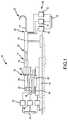
- FIG. 1is a schematic illustration of an embodiment of a robotic surgical system.
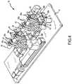
- FIG. 2is a perspective view of one embodiment of a catheter holding device with a catheter placed therein.
- FIG. 3is an end view of the catheter holding device of FIG. 2 .
- FIG. 4is a perspective view of one embodiment of a catheter holding device with a catheter secured therein.
- FIG. 5is an end view of the catheter holding device of FIG. 4 .
- FIG. 6illustrates an exemplary steerable catheter such as may be used in the robotic surgical system.
- FIG. 7depicts automatic control of the robotic surgical system according to a predetermined program.
- FIG. 8depicts a user manually controlling the robotic surgical system via an input device.
- FIG. 9depicts the user of FIG. 8 manually controlling the steerable catheter after having removed it from the robotic surgical system.
- FIG. 10schematically illustrates a contact sensing surgical system.
- FIG. 11is a high-level flowchart of a contact sensing methodology.
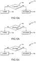
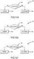
- FIGS. 12 a through 12 oillustrate alternative implementations of the decision process for indicating a change in proximity or degree of contact in the high-level flowchart of FIG. 11 .
- FIG. 13 ais an exemplary plot of tissue parameter versus either time or probe distance as measured by a contact sensing surgical system.
- FIG. 13 bis the derivative of the plot in FIG. 13 a.
- FIG. 1schematically illustrates an embodiment of a robotic surgical system 10 for robotic manipulation and control of a medical device 12 .
- Medical device 12is preferably a catheter, which may be any type of catheter, including, by way of example only and without limitation, an ablation catheter, a guide wire catheter, an introducer catheter, a probe, or a stylet. It should be understood, however, that any other therapeutic, diagnostic, or assistive medical device may be controlled by robotic surgical system 10 without departing from the scope of the present invention.
- Such other devicesinclude, but are not limited to, syringes, electrophoresis devices, iontophoresis devices, transdermal pharmaceutical delivery devices, myoblast delivery devices, stem cell delivery devices, ablation devices, stents, and pacemaker leads, which may be carried on or delivered by a catheter.
- robotic surgical system 10may be used to manipulate and control more than one medical device 12 in accordance with the quick installation and removal feature described herein. Accordingly, the terms “medical device,” “probe,” “therapeutic device,” and “catheter” are used interchangeably herein.
- Robotic surgical system 10generally includes a track 14 , a catheter holding device 16 , a translation servo mechanism 18 , a catheter deflection control mechanism 20 , a deflection servo mechanism 22 , and a controller 24 operatively coupled to at least one of translation servo mechanism 18 and deflection servo mechanism 22 .
- Translation and deflection servo mechanisms 18 , 22may be any type of device for providing mechanical control at a distance, including continuous motors, stepper motors, hydraulic actuators, pulley systems, and other devices known to those of ordinary skill in the art.
- Catheter deflection control mechanism 20 and deflection servo mechanism 22are collectively referred to herein as a “catheter deflection mechanism.”
- Catheter holding device 16includes a catheter receiving portion 26 .
- Catheter receiving portion 26is configured to receive catheter 12 by installing a catheter control handle 28 , located near a proximal end 30 of catheter 12 , into catheter receiving portion 26 .
- catheter receiving portion 26is adapted for quick installation and removal of any type of catheter 12 (or, as noted above, another medical device), thereby facilitating the installation of device 12 for control by robotic surgical system 10 and removal of device 12 for manual control (e.g., user manipulation of catheter control handle 28 ).
- catheter control handle 28may be secured in catheter receiving portion 26 by a frictional fit or with one or more quick-release fasteners.
- catheter control handle 28may include mating threaded portions to permit catheter control handle 28 to be screwed into catheter holding device 16 .
- catheter control handle 28is clamped or strapped in place in catheter receiving portion 26 .
- An adaptermay also be used to facilitate the reception of catheter control handle 28 within catheter receiving portion 26 .
- catheter holding device 16is illustrated in FIGS. 2 and 3 with catheter control handle 28 placed, but not secured, therein.
- Catheter holding device 16includes a base plate 32 and a plurality of upstanding support plates 34 .
- Support plates 34support cams 36 , which are connected to pulley systems 38 .
- Catheter control handle 28is received downwardly through an opening into the catheter receiving portion 26 and onto belts 40 of pulley systems 38 .
- belts 40rotate upper and lower pulleys 38 a , 38 b in the direction of arrows a.
- Thisurges cams 36 downwards via links 42 and draws upper pulleys 38 a , 38 b towards one another via links 44 , while simultaneously wrapping the belts 40 about catheter control handle 28 .
- Catheter control handle 28is thereby secured within catheter receiving portion 26 as shown in FIGS. 4 and 5 .
- the userneed only release cams 36 , which reverses the process described above and opens catheter receiving portion 26 .
- Catheter holding device 16is translatably associated with track 14 .
- the phrase “translatably associated with”encompasses all types of relative lateral motion between catheter holding device 16 and track 14 .
- catheter holding device 16may slide relative to track 14 .
- catheter holding device 16may move laterally along a screw mechanism 46 , such as a worm gear, a lead screw, or a ball screw, attached to track 14 .
- catheter holding device 16has a translation range relative to track 14 (i.e., the lateral distance that catheter holding device 16 can travel relative to track 14 between extremes) of at least about 5 cm, the approximate width of a human heart. More preferably, the translation range of catheter holding device 16 relative to track 14 is at least about 10 cm.
- a carriage 48is translatably mounted on track 14 via screw mechanism 46 .
- Catheter holding device 16is mounted on carriage 48 such that catheter holding device 16 translates relative to track 14 with carriage 48 .
- base plate 32may be fixedly or removably mounted on carriage 48 .
- catheter holding device 16may be integrally formed with carriage 48 as a single assembly (i.e., base plate 32 and carriage 48 may be a single, unitary component).
- catheter holding device 16may be translatably mounted directly on track 14 without an intervening carriage.
- Translation servo mechanism 18is operatively coupled to catheter holding device 16 and adapted to control translation of catheter holding device 16 relative to track 14 in order to adjust the lateral position of catheter holding device 16 along track 14 .
- translation servo mechanism 18is operatively coupled to carriage 48 in order to move carriage 48 , and therefore catheter holding device 16 mounted thereon, laterally along track 14 .
- translation servo mechanism 18drives screw mechanism 46 , thereby moving carriage 48 laterally therealong.
- Deflection servo mechanism 22is operatively coupled to and adapted to control catheter deflection control mechanism 20 .
- deflection servo mechanism 22is operatively coupled to catheter deflection control mechanism 20 such that deflection servo mechanism 22 can rotate catheter deflection control mechanism 20 .
- Either or both of deflection servo mechanism 22 and catheter deflection control mechanism 20may be mounted on carriage 48 in order to simplify the transmission system linking deflection servo mechanism 22 and catheter deflection control mechanism 20 .
- catheter deflection control mechanism 20is incorporated in catheter holding device 16 , for example by utilizing pulley systems 38 , and in particular belts 40 , as further described below.
- catheter deflection control mechanism 20may also be separated from catheter holding device 16 without departing from the spirit and scope of the present invention.
- Controller 24is adapted to control at least one of translation servo mechanism 18 and deflection servo mechanism 22 in order to navigate catheter 12 received in catheter holding device 16 . It should also be noted that the use of multiple controllers to control translation servo mechanism 18 and deflection servo mechanism 22 is regarded as within the scope of the present invention.
- the term “controller”refers to a device that controls the movement or actuation of one or more robotic systems (that is, the component responsible for providing command inputs to the servo mechanisms).
- controllershould be regarded as encompassing both a singular, integrated controller and a plurality of controllers for actuating one or more robotic systems.
- catheter 12is preferably a steerable catheter including at least one pull wire 50 extending from catheter control handle 28 near proximal end 30 of catheter 12 to a distal end 52 of catheter 12 .
- Pull wires 50may be coupled to at least one pull ring 54 , also located near distal end 52 of catheter 12 . When placed in tension, pull wires 50 deflect distal end 52 of catheter 12 into various configurations. As one of skill in the art will understand, additional pull wires 50 will enhance the deflection versatility of distal end 52 of catheter 12 .
- a single pull wire 50 with a single point of attachment to pull ring 54will permit distal end 52 of catheter 12 to deflect on a single axis, and perhaps in only one direction, for example upwards relative to FIG. 6 .
- distal end 52 of catheter 12may be deflected in two directions, for example both upwards and downwards relative to FIG. 6 .
- a catheter 12 with four pull wires 50 attached to pull ring 54 at about 90° intervalscan deflect in four directions, for example upwards, downwards, and into and out of the plane of the paper relative to FIG. 6 .
- One or more catheter deflection actuators 58may be provided on catheter control handle 28 to selectively tension one or more pull wires 50 , thereby controlling the direction and degree of deflection of distal end 52 of catheter 12 .
- one or more knobsmay be provided, rotation of which selectively tension one or more pull wires 50 .
- catheter deflection actuators 58may take many other forms, including, but not limited to, sliders and switches, without departing from the spirit and scope of the present invention. Additionally, it is contemplated that rotating catheter control handle 28 itself may selectively tension pull wires 50 and deflect distal end 52 of catheter 12 .
- catheter 12when catheter control handle 28 is received within catheter receiving portion 26 , catheter 12 translates relative to track 14 with catheter holding device 16 , thereby providing a first degree of freedom permitting catheter 12 to be advanced into and retracted from a patient's body. Additionally, catheter 12 is operatively coupled to catheter deflection control mechanism 20 such that actuation of catheter deflection control mechanism 20 causes distal end 52 of catheter 12 to deflect, thereby providing a second degree of freedom to catheter 12 .
- catheter deflection actuator 58may be operatively coupled to catheter deflection control mechanism 20 such that catheter deflection control mechanism 20 can actuate catheter deflection actuator 58 to selectively tension one or more pull wires 50 and deflect the distal end 52 of catheter 12 by a desired amount in a desired direction.
- rotating catheter deflection control mechanism 20will rotate catheter deflection actuator 58 in turn, thereby selectively tensioning one or more pull wires 50 within catheter 12 .
- the transmission system between catheter deflection control mechanism 20 and catheter deflection actuator 58may be a frictional fit provided, for example, by rubberized coatings surrounding catheter deflection control mechanism 20 and catheter deflection actuator 58 .
- catheter deflection control mechanism 20 and catheter deflection actuator 58may be coupled with mating gear teeth or knurling.
- belts 40frictionally engage catheter control handle 28 . They may also engage catheter deflection actuator 58 . Thus, if pulley system 38 is driven by deflection servo mechanism 22 , belts 40 may rotate catheter control handle 28 , catheter deflection actuator 58 , or both, in order to selectively tension one or more pull wires 50 and deflect distal end 52 of catheter 12 .
- catheter deflection control mechanism 20 and catheter deflection actuator 58are merely exemplary and can be modified without departing from the spirit and scope of the invention.
- catheter deflection actuator 58is a slider rather than a knob
- catheter deflection control mechanism 20may be suitably modified, or even replaced as a modular unit, to actuate a slider. This facilitates the quick connect/disconnect operation of robotic surgical system 10 by allowing easy installation and interconnection between off-the-shelf medical devices of varying construction and robotic surgical system 10 .
- the inclusion of additional pull wires 50 in catheter 12increases the number of directions in which distal end 52 of catheter 12 can deflect. This is referred to herein as “deflection versatility.” Where relatively few pull wires 50 (e.g., fewer than about four pull wires 50 ) are used, however, compensation for lost deflection versatility may be had by rotating catheter 12 about its axis. For example, in a catheter using only a single pull wire 50 with a single point of attachment to pull ring 54 , permitting the catheter to deflect only in one direction, the catheter may be deflected in the opposite direction simply by rotating it 180° about its axis. Similarly, a catheter that can deflect in two directions 180° apart can be deflected in the directions midway therebetween by rotating the catheter 90° about its axis.
- catheter receiving portion 26is rotatable.
- An example of such a rotatable catheter receiving portionis catheter receiving portion 26 defined by pulley system 38 depicted in FIGS. 2-5 .
- a rotation servo mechanism 60is operatively coupled to rotatable catheter receiving portion 26 and adapted to control rotatable catheter receiving portion 26 .
- pulley system 38may be driven by rotation servo mechanism 60 , thereby engaging belts 40 to rotate catheter 12 about its axis.
- rotation servo mechanism 60may be mounted on carriage 48 or affixed to catheter holding device 16 such that rotation servo mechanism 60 translates relative to track 14 with catheter holding device 16 . This arrangement creates a fixed-distance relationship between rotation servo mechanism 60 and catheter holding device 16 , which can simplify the transmission system coupling rotation servo mechanism 60 to catheter holding device 16 .
- catheter 12When installed in catheter holding device 16 , catheter 12 rotates with catheter receiving portion 26 , thereby providing a third degree of freedom to catheter 12 and compensating for low deflection versatility attributable to a relatively lower number of pull wires 50 .
- Catheter receiving portion 26is preferably rotatable at least about 360° about its axis, such that catheter 12 received therein is also rotatable at least about 360° about its axis, thereby facilitating deflection of distal end 52 of catheter 12 in substantially any direction, significantly enhancing the deflection versatility of the distal end 52 of the catheter 12 .
- Catheter receiving portion 26may also be designed to rotate about 720° or more about its axis.
- Rotating catheter 12 by rotating catheter receiving portion 26may cause inadvertent deflection of distal end 52 of catheter 12 .
- catheter deflection actuator 58may remain stationary, rather than rotating with catheter control handle 28 , if the torque applied by rotation servo mechanism 60 is insufficient to overcome the inertia of catheter deflection control mechanism 20 . That is, catheter deflection actuator 58 may bind against catheter deflection control mechanism 20 , causing relative rotation between catheter control handle 28 and catheter deflection actuator 58 . This relative rotation may result in uncommanded tensioning of one or more pull wires 50 , inadvertently deflecting distal end 52 of catheter 12 .
- controller 24may be operatively coupled to both rotation servo mechanism 60 and deflection servo mechanism 22 .
- Controller 24is adapted to control at least one of deflection servo mechanism 22 and rotation servo mechanism 60 , and preferably to simultaneously control both deflection servo mechanism 22 and rotation servo mechanism 60 , to maintain a substantially constant deflection of distal end 52 as catheter receiving portion 26 and catheter 12 rotate.
- controller 24may simultaneously command deflection servo mechanism 22 to actuate catheter deflection control mechanism 20 to counter-rotate, thereby substantially eliminating relative rotation between the catheter deflection actuator 58 and catheter control handle 28 , helping to maintain a substantially constant deflection of catheter 12 .
- controller 24may simultaneously command deflection servo mechanism 22 to decouple catheter deflection control mechanism 20 from catheter deflection actuator 58 , thereby permitting catheter deflection actuator 58 to rotate freely with catheter control handle 28 .
- controller 24may be configured to eliminate the need to couple deflection servo mechanism 22 and rotation servo mechanism 60 through a mechanical transmission system such as a differential. Further, though described herein as a single controller adapted to control the translation, deflection, and rotation servo mechanisms 18 , 22 , 60 , multiple controllers may be used without departing from the spirit and scope of the present invention.
- An introducer 62preferably a steerable introducer, and most preferably an AgilisTM steerable introducer, may be provided as part of robotic surgical system 10 .
- a proximal end 64 of introducer 62is preferably stationary, while a distal end 66 of introducer 62 extends into a patient (not shown for clarity) to a location proximate a target site (the term “target” is used herein to refer to a location at which treatment or diagnosis occurs).
- Introducer 62may be steerable via a robotic control system 68 including at least one servo mechanism 70 adapted to control distal end 66 of introducer 62 in at least one degree of freedom.
- robotic control system 68includes three servo mechanisms 70 adapted to control distal end 66 of the introducer 62 in three degrees of freedom (translation, deflection, and rotation), resulting in a total of six degrees of freedom for robotic surgical system 10 , and at least one controller 72 adapted to control servo mechanisms 70 . Similar control principles may be applied to steerable introducer 62 as are described herein with respect to robotic surgical system 10 and medical device 12 .
- distal end 52 of catheter 12is a function not only of the input to catheter deflection actuator 58 (i.e., the selective tensioning of one or more pull wires 50 ), but also of the extent to which catheter 12 is advanced beyond a generally rigid sheath, such as introducer 62 . That is, the further distal end 52 of catheter 12 is advanced beyond distal end 66 of introducer 62 , the greater the deflection of distal end 52 of catheter 12 will be for a given input at catheter deflection actuator 58 .
- catheter deflection control mechanism 20it is therefore desirable to calibrate the deflection of distal end 52 of catheter 12 in terms of both catheter deflection control mechanism inputs and extensions of catheter 12 beyond distal end 66 of introducer 62 .
- catheter deflection control mechanism inputsmay be correlated with deflections of distal end 52 for a given extension of catheter 12 beyond distal end 66 of introducer 62 .
- a similar processmay be performed for a multiple different extensions of catheter 12 beyond distal end 66 of introducer 62 , resulting in a family of calibration curves relating catheter deflection control mechanism inputs to deflections of distal end 52 of catheter 12 .
- Each curvecorresponds to a particular extension of catheter 12 beyond distal end 66 of introducer 62 ; the amount of extension of catheter 12 beyond distal end 66 of introducer 62 may be derived, at least in part, from the amount of translation of catheter holding device 16 relative to track 14 .
- an expandable and collapsible tubular shaft 74substantially surrounds at least a portion of catheter 12 , such as the region of catheter 12 between catheter holding device 16 and proximal end 64 of introducer 62 .
- shaft 74is sterilized before use along with other relevant components of robotic surgical system 10 .
- catheter holding device 16translates to advance catheter 12 into the patient (i.e., to the right in FIG. 1 )
- tubular shaft 74collapses upon itself.
- tubular shaft 74expands.
- tubular shaft 74is assembled from a plurality of telescoping tubular elements 76 . It is contemplated, however, that tubular shaft 74 may alternatively be an accordion-pleated or other expandable and collapsible structure.
- robotic surgical system 10may be employed to robotically navigate catheter 12 into and through the patient and to one or more sites, which may be target sites, within the patient's body by actuating one or more of translation servo mechanism 18 , deflection servo mechanism 22 , and rotation servo mechanism 60 (if present) via controller 24 .
- Robotic surgical system 10may operate automatically according to a computerized program as executed by controller 24 ( FIG. 7 ).
- robotic surgical system 10may control robotic surgical system 10 through an appropriate set of controls 78 , such as a three-dimensional joystick (e.g., a joystick with three input axes), a steering yoke, or another suitable input device or collection of such devices permitting the user to robotically steer catheter 12 ( FIG. 8 ).
- controls 78such as a three-dimensional joystick (e.g., a joystick with three input axes), a steering yoke, or another suitable input device or collection of such devices permitting the user to robotically steer catheter 12 ( FIG. 8 ).
- catheter 12can be quickly and easily disconnected from catheter holding device 16 .
- the usermay disconnect catheter 12 from the catheter holding device 16 as described above.
- the usermay navigate catheter 12 manually for as long as desired, and then replace it into catheter holding device 16 and resume robotic control.
- FIG. 9illustrates the user manually operating catheter 12 after having removed it from catheter holding device 16 .
- multiple robotic surgical systems controlling multiple medical devicesmay be employed during a procedure.
- a first robotic surgical systemmay control an ultrasonic imaging transducer, while a second robotic surgical system may control an ablation catheter.
- a single controller, or multiple cooperating controllersmay coordinate the multiple medical devices and the multiple robotic surgical systems, for example in conjunction with a single localization system, or alternatively by utilizing data from the ultrasonic imaging transducer to control the movement of the ablation catheter.
- Robotic surgical system 10facilitates precise and accurate navigation of medical device 12 within the patient's body.
- medical device 12is manipulated primarily robotically, the physician will experience considerably less fatigue during the surgical procedure.
- robotic controlpermits a substantially increased degree of complexity in the control and actuation mechanisms that may be incorporated into medical device 12 over those that may be used in a medical device 12 intended solely for human control, enabling an increase in the versatility of medical device 12 .
- robotic surgical system 10may be remote from robotic surgical system 10 .
- an expert physician in one citymay control robotic surgical system 10 located in a second city via a computer network, such as the Internet.
- FIG. 10schematically illustrates a surgical system 80 equipped to sense contact between a probe, such as catheter 12 , and a tissue surface 82 , such as a cardiac wall.
- Probe 12includes a sensor or instrument 84 carried thereon, preferably at distal end 52 of probe 12 , for measuring the value of a parameter (referred to herein as P) of tissue surface 82 either periodically (that is, with a relatively fixed interval between measurements) or episodically (that is, with a variable interval between measurements).
- sensor 84is an electrophysiology sensor capable of measuring one or more electrophysiology characteristics, including, but not limited to, impedance, phase angle, electrogram amplitude, optical feedback, and ultrasonic feedback.
- the precisely calibrated systemmay be a robotically controlled system to move probe 12 within the patient's body, such as robotic surgical system 10 described herein. It is also contemplated that measurements of the position of probe 12 within the patient's body may be made using a precisely locally- or universally-calibrated positional feedback (i.e., localization) system 86 in conjunction with a location or position electrode 88 carried on probe 12 .
- the positional feedback systemis the Ensite NavXTM system of St. Jude Medical, Inc., which includes pairs of electrodes 90 defining measurement axes by which the position of probe 12 may be measured.
- a processormonitors the value of the tissue parameter measured by sensor 84 as probe 12 moves within the patient's body.
- the processormay be incorporated in a computer system 92 .
- a single processor within computer system 92will be referred to, though it is contemplated that multiple computer systems 92 and/or multiple processors within a single computer system 92 may be used to practice the various aspects of the present invention. Further, one or more processor functions described herein may be integrated in a single processor without departing from the scope of the present invention.
- probe 12may be moved by a robotically-controlled system capable of precise movements on the order of less than about 5 mm, more preferably on the order of less than about 2 mm, and most preferably on the order of less than about 1 mm.
- the movements of probe 12are precisely measured by a positional feedback system 86 with a margin of error of less than about 5 mm, preferably less than about 2 mm, and more preferably less than about 1 mm.
- ⁇ se.g., as precisely moved by robotic surgical system 10 or precisely measured by positional feedback system 86
- a corresponding amount and rate of change in the tissue parameter between measurementscan be anticipated for a situation where there is no change in the proximity or degree of contact between probe 12 and tissue surface 82 .
- the processormonitors the tissue parameter for an indicator of proximity or degree of contact between probe 12 and tissue surface 82 and indicates a change in the proximity or degree of contact between probe 12 and tissue surface 82 based on the monitored tissue parameter. In particular, the processor reports the change in either proximity or degree of contact based on either the amount of change in the tissue parameter or the rate of change in the tissue parameter between measurements, and preferably between successive measurements, thereof.
- the term “proximity”refers to the relationship between probe 12 and tissue surface 82 when probe 12 is not in contact with tissue surface 82 ; it is, in lay terms, a measure of how close probe 12 is to tissue surface 82 .
- degree of contactrefers to the relationship between probe 12 and tissue surface 82 when probe 12 is in contact with tissue surface 82 ; it is, in lay terms, a measure of how hard probe 12 is pressing into tissue surface 82 .
- a contact sensing methodis illustrated in the high-level flowchart of FIG. 11 .
- Probe 12is navigated into the patient's body and into meaningful proximity with tissue surface 82 in step 100 .
- the term “meaningful proximity”refers to probe 12 being sufficiently close to tissue surface 82 such that sensor 84 can capture useful electrophysiology information about surface 82 , and thus encompasses both contact and non-contact relationships between probe 12 and tissue surface 82 .
- probe 12is moved using a calibrated system, such as robotic surgical system 10 , moved and located using a calibrated system, such as positional feedback system 86 , or both.
- a calibrated systemsuch as robotic surgical system 10
- a calibrated systemsuch as positional feedback system 86
- the tissue parameter at distal end 52 of probe 12is measured, either periodically or episodically, using sensor 84 (steps 102 , 104 , and 106 ).
- An amount of change ( ⁇ P) in the measured tissue parameter between successive measurements (P n and P n+1 )is calculated in step 108 .
- the processorindicates a change in proximity or degree of contact between probe 12 and tissue surface 82 based upon the amount of change in the measured tissue parameter in step 110 .
- a number of algorithmsmay be used to identify the change in proximity or degree of contact between probe 12 and tissue surface 82 in step 110 .
- a first algorithmillustrated in FIG. 12 a , the amount of change in the measured tissue parameter ( ⁇ P) is compared to a predetermined range of values ranging from a lower limit (LL) to an upper limit (UL) in step 114 a .
- LLlower limit
- ULupper limit
- FIGS. 12 a through 12 oabsolute values are used in order to account for potential negative values of ⁇ P.
- a changeis indicated when the amount of change in the measured parameter falls outside the predetermined range of values (step 116 a ); no change is indicated when the amount of change in the measured parameter falls within the predetermined range of values (step 118 a ).
- the predetermined range of valuesmay be user selectable, and may correspond generally to the anticipated amount of change in the measured tissue parameter between measurements when there is no change in the proximity or degree of contact between probe 12 and tissue surface 82 for a given ⁇ s.
- Predeterminedis used herein to refer to values that are set in advance of applying the contact sensing algorithm; for example, the values (i.e., UL and LL) may be based upon a percentage variation in the anticipated change in the measured tissue parameter, which percentage may also be user selectable.
- the amount of change in the measured tissue parameteris compared to a change threshold, with the change indication based upon whether or not the measured tissue parameter crosses the change threshold.
- the change thresholdmay correspond generally to the maximum anticipated amount of change in the measured tissue parameter between successive measurements for a given ⁇ s ( ⁇ P MAX ).
- ⁇ P MAXthe maximum anticipated amount of change in the measured tissue parameter between successive measurements for a given ⁇ s
- the thresholdcorresponds generally to the minimum anticipated amount of change in the measured tissue parameter between successive measurements for a given ⁇ s ( ⁇ P MIN ), which would reverse the conditions for indicating change or no change in proximity or degree of contact.
- the change thresholdmay be user selectable, and may be calculated as a percentage variation in the anticipated amount of change in the measured tissue parameter for a given ⁇ s, which percentage may itself be user selectable.
- the change in proximity or degree of contactis indicated based upon a rate of change in the measured tissue parameter with respect to either the time between measurements ( ⁇ P/ ⁇ t) or the distance traveled by probe 12 between measurements ( ⁇ P/ ⁇ s).
- the rate of changemay also be calculated as a derivative of the measured tissue parameter with respect to time (dP/dt) or probe distance traveled (dP/ds).
- the rate of changemay be calculated as a first derivative of the tissue parameter, a second derivative of the tissue parameter, or any further derivative of the tissue parameter.
- any of these variablesmay be calculated from the amount of change in the measured tissue parameter and the time between measurements or the precisely determined distance traveled by probe 12 between measurements.
- the decision processes for indicating change in proximity or degree of contact based upon rate of change variablesare substantially analogous to the algorithms described with respect to the amount of change in the measured tissue parameter (i.e., comparison to a predetermined range of values or comparison to a rate of change threshold). These alternative algorithms are illustrated in FIGS. 12 d - 12 o.
- step 114 bshown in FIG. 12 b
- step 114 cshown in FIG. 12 c
- step 114 ais the analogue to step 114 a for the algorithm illustrated in FIG. 12 c
- step 114 cis the analogue to step 114 a for the algorithm illustrated in FIG. 12 c ; and so forth.
- FIG. 13 ais a representative chart of the measured tissue parameter as a function of time (t) or probe distance traveled (s), while FIG. 13 b illustrates the derivative of the curve of FIG. 13 a .
- Pvaries only slightly.
- ⁇ Pis thus quite small, so ⁇ P/ ⁇ t, ⁇ P/ ⁇ s, dP/dt, and dP/ds vary slightly about zero (dP/dt and dP/ds are illustrated in FIG. 13 b ).
- the contact sensing methods described aboveare useful in monitoring for a change indicative of probe 12 making contact with tissue surface 82 , a change indicative of probe 12 breaking contact with tissue surface 82 , or a change indicative of a change in the degree of contact between probe 12 and tissue surface 82 .
- the methodmay provide an indicator of whether probe 12 is beginning to break contact with tissue surface 82 or is potentially being traumatically driven into tissue surface 82 .
- This informationmay be used by the user and/or robotic surgical system 10 (e.g., controller 24 ) as feedback to adjust the movement of probe 12 to maintain a particular degree of contact with tissue surface 82 on an ongoing basis in order to improve the quality or efficiency of the medical treatment.
- a spike in a derivative of the tissue parametermay indicate that the ablation catheter has broken contact with the cardiac surface and is therefore no longer creating a substantially continuous lesion and that appropriate corrective action is necessary to bring the ablation catheter back into contact with the cardiac surface.
- the spikemay indicate that the modeling probe has broken contact with the surface being modeled such that the collection of geometry points should be suspended in order to avoid capturing erroneous data.
- robotic surgical system 10may be modified to incorporate additional servo mechanisms and controllers operating on additional degrees of freedom.
- the contact sensing methodologyhas been described in connection with a robotically controlled medical device, it could also be implemented in a manually controlled medical device. It should also be understood that, rather than utilizing absolute values in the various contact sensing algorithms described herein, the thresholds or limits may be appropriately adjusted to compensate for negative values of ⁇ P, for example by taking the opposite of all thresholds or limits and reversing the comparator (i.e., changing ⁇ to >) upon detecting that ⁇ P is less than zero.
- the devices and methods disclosed hereinare capable of use both epicardially and endocardially.
- All directional referencese.g., upper, lower, upward, downward, left, right, leftward, rightward, top, bottom, above, below, vertical, horizontal, clockwise, and counterclockwise
- Joinder referencese.g., attached, coupled, connected, and the like
- Joinder referencesare to be construed broadly and may include intermediate members between a connection of elements and relative movement between elements. As such, joinder references do not necessarily infer that two elements are directly connected and in fixed relation to each other.
Landscapes
- Health & Medical Sciences (AREA)
- Life Sciences & Earth Sciences (AREA)
- Surgery (AREA)
- Engineering & Computer Science (AREA)
- Medical Informatics (AREA)
- Public Health (AREA)
- Biomedical Technology (AREA)
- Heart & Thoracic Surgery (AREA)
- Veterinary Medicine (AREA)
- Molecular Biology (AREA)
- Animal Behavior & Ethology (AREA)
- General Health & Medical Sciences (AREA)
- Nuclear Medicine, Radiotherapy & Molecular Imaging (AREA)
- Robotics (AREA)
- Physics & Mathematics (AREA)
- Biophysics (AREA)
- Pathology (AREA)
- Manipulator (AREA)
- Surgical Instruments (AREA)
Abstract
Description
Claims (6)
Priority Applications (3)
| Application Number | Priority Date | Filing Date | Title |
|---|---|---|---|
| US11/647,272US10863945B2 (en) | 2004-05-28 | 2006-12-29 | Robotic surgical system with contact sensing feature |
| PCT/US2007/080701WO2008045827A2 (en) | 2006-10-12 | 2007-10-08 | Robotic surgical system with contact sensing feature |
| US13/778,893US9237930B2 (en) | 2005-05-27 | 2013-02-27 | Robotically controlled catheter and method of its calibration |
Applications Claiming Priority (4)
| Application Number | Priority Date | Filing Date | Title |
|---|---|---|---|
| US57574104P | 2004-05-28 | 2004-05-28 | |
| US11/139,908US7632265B2 (en) | 2004-05-28 | 2005-05-27 | Radio frequency ablation servo catheter and method |
| US85104206P | 2006-10-12 | 2006-10-12 | |
| US11/647,272US10863945B2 (en) | 2004-05-28 | 2006-12-29 | Robotic surgical system with contact sensing feature |
Related Parent Applications (1)
| Application Number | Title | Priority Date | Filing Date |
|---|---|---|---|
| US11/139,908Continuation-In-PartUS7632265B2 (en) | 2004-05-28 | 2005-05-27 | Radio frequency ablation servo catheter and method |
Publications (2)
| Publication Number | Publication Date |
|---|---|
| US20070181139A1 US20070181139A1 (en) | 2007-08-09 |
| US10863945B2true US10863945B2 (en) | 2020-12-15 |
Family
ID=39283547
Family Applications (1)
| Application Number | Title | Priority Date | Filing Date |
|---|---|---|---|
| US11/647,272Active2034-03-21US10863945B2 (en) | 2004-05-28 | 2006-12-29 | Robotic surgical system with contact sensing feature |
Country Status (2)
| Country | Link |
|---|---|
| US (1) | US10863945B2 (en) |
| WO (1) | WO2008045827A2 (en) |
Families Citing this family (40)
| Publication number | Priority date | Publication date | Assignee | Title |
|---|---|---|---|---|
| US7894871B2 (en)* | 2006-12-29 | 2011-02-22 | St. Jude Medical, Atrial Fibrillation Division, Inc. | Filtering method for surface modeling |
| US9549689B2 (en) | 2007-03-09 | 2017-01-24 | St. Jude Medical, Atrial Fibrillation Division, Inc. | System and method for correction of inhomogeneous fields |
| US10433929B2 (en)* | 2007-03-09 | 2019-10-08 | St. Jude Medical, Atrial Fibrillation Division, Inc. | System and method for local deformable registration of a catheter navigation system to image data or a model |
| CA2712607A1 (en)* | 2008-01-25 | 2009-07-30 | Mcmaster University | Surgical guidance utilizing tissue feedback |
| US8083691B2 (en) | 2008-11-12 | 2011-12-27 | Hansen Medical, Inc. | Apparatus and method for sensing force |
| US9307931B2 (en)* | 2008-12-31 | 2016-04-12 | St. Jude Medical, Atrial Fibrillation Division, Inc. | Multiple shell construction to emulate chamber contraction with a mapping system |
| WO2010093603A1 (en) | 2009-02-11 | 2010-08-19 | Boston Scientific Scimed, Inc. | Insulated ablation catheter devices and methods of use |
| AU2010324494B2 (en) | 2009-11-27 | 2014-11-06 | Centre For Surgical Invention & Innovation | Automated in-bore MR guided robotic diagnostic and therapeutic system |
| US20120095322A1 (en)* | 2010-09-08 | 2012-04-19 | Tsekos Nikolaos V | Devices, systems and methods for multimodal biosensing and imaging |
| US10362963B2 (en) | 2011-04-14 | 2019-07-30 | St. Jude Medical, Atrial Fibrillation Division, Inc. | Correction of shift and drift in impedance-based medical device navigation using magnetic field information |
| US9901303B2 (en) | 2011-04-14 | 2018-02-27 | St. Jude Medical, Atrial Fibrillation Division, Inc. | System and method for registration of multiple navigation systems to a common coordinate frame |
| US10918307B2 (en) | 2011-09-13 | 2021-02-16 | St. Jude Medical, Atrial Fibrillation Division, Inc. | Catheter navigation using impedance and magnetic field measurements |
| JP5762118B2 (en) | 2011-05-02 | 2015-08-12 | キヤノン株式会社 | Light irradiation apparatus, control method therefor, and object information acquisition apparatus |
| US9603659B2 (en) | 2011-09-14 | 2017-03-28 | Boston Scientific Scimed Inc. | Ablation device with ionically conductive balloon |
| JP2015506234A (en) | 2012-01-10 | 2015-03-02 | ボストン サイエンティフィック サイムド,インコーポレイテッドBoston Scientific Scimed,Inc. | Electrophysiology system |
| EP2666428B1 (en) | 2012-05-21 | 2015-10-28 | Universität Bern | System and method for estimating the spatial position of a tool within an object |
| JP2016502885A (en) | 2012-12-20 | 2016-02-01 | ボストン サイエンティフィック サイムド,インコーポレイテッドBoston Scientific Scimed,Inc. | Real-time feedback of electrode contact during mapping |
| US10912476B2 (en) | 2013-01-16 | 2021-02-09 | University Of Vermont | Catheters, systems, and related methods for mapping, minimizing, and treating cardiac fibrillation |
| US9301713B2 (en) | 2013-11-19 | 2016-04-05 | Pacesetter, Inc. | Method and system to assess mechanical dyssynchrony based on motion data collected by a navigation system |
| US9814406B2 (en) | 2013-11-19 | 2017-11-14 | Pacesetter, Inc. | Method and system to identify motion data associated with consistent electrical and mechanical behavior for a region of interest |
| US9314191B2 (en) | 2013-11-19 | 2016-04-19 | Pacesetter, Inc. | Method and system to measure cardiac motion using a cardiovascular navigation system |
| US9302099B2 (en) | 2014-05-05 | 2016-04-05 | Pacesetter, Inc. | System and method for evaluating lead stability of an implantable medical device |
| US9895076B2 (en) | 2014-05-05 | 2018-02-20 | Pacesetter, Inc. | Method and system to determine cardiac cycle length in connection with cardiac mapping |
| US9763591B2 (en) | 2014-05-05 | 2017-09-19 | Pacesetter, Inc. | Method and system to subdivide a mapping area for mechanical activation analysis |
| US9364170B2 (en) | 2014-05-05 | 2016-06-14 | Pacesetter, Inc. | Method and system to characterize motion data based on neighboring map points |
| US10285647B2 (en) | 2014-05-05 | 2019-05-14 | Pacesetter Inc. | Method and system to automatically assign map points to anatomical segments and determine mechanical activation time |
| US10105077B2 (en) | 2014-05-05 | 2018-10-23 | Pacesetter, Inc. | Method and system for calculating strain from characterization data of a cardiac chamber |
| US9380940B2 (en) | 2014-05-05 | 2016-07-05 | Pacesetter, Inc. | Method and system for displaying a three dimensional visualization of cardiac motion |
| US9861823B2 (en) | 2014-05-05 | 2018-01-09 | Pacesetter, Inc. | Cardiac resynchronization system and method |
| US9700233B2 (en) | 2014-05-05 | 2017-07-11 | Pacesetter, Inc. | Method and system to equalizing cardiac cycle length between map points |
| GB201417164D0 (en) | 2014-09-29 | 2014-11-12 | Renishaw Plc | Measurement Probe |
| JP2017529169A (en) | 2014-10-13 | 2017-10-05 | ボストン サイエンティフィック サイムド,インコーポレイテッドBoston Scientific Scimed,Inc. | Tissue diagnosis and treatment using mini-electrodes |
| WO2016065337A1 (en) | 2014-10-24 | 2016-04-28 | Boston Scientific Scimed Inc. | Medical devices with a flexible electrode assembly coupled to an ablation tip |
| US9743854B2 (en) | 2014-12-18 | 2017-08-29 | Boston Scientific Scimed, Inc. | Real-time morphology analysis for lesion assessment |
| CN109069840B (en) | 2016-02-04 | 2022-03-15 | 心脏起搏器股份公司 | Delivery system with force sensor for leadless cardiac devices |
| WO2018176457A1 (en)* | 2017-04-01 | 2018-10-04 | 中国科学院深圳先进技术研究院 | Catheter twisting device for vessel interventional surgery robot |
| US10918310B2 (en)* | 2018-01-03 | 2021-02-16 | Biosense Webster (Israel) Ltd. | Fast anatomical mapping (FAM) using volume filling |
| JP7387502B2 (en)* | 2019-03-19 | 2023-11-28 | キヤノンメディカルシステムズ株式会社 | Ultrasonic automatic scanning system, ultrasound diagnostic equipment, ultrasound scanning support equipment |
| CN112190335B (en)* | 2020-10-22 | 2022-01-18 | 北京唯迈医疗设备有限公司 | Intervene supplementary operation robot |
| CN112353491B (en)* | 2020-10-29 | 2021-09-14 | 北京唯迈医疗设备有限公司 | Universal robot for interventional radiography and therapeutic surgery |
Citations (225)
| Publication number | Priority date | Publication date | Assignee | Title |
|---|---|---|---|---|
| US4510574A (en) | 1981-09-09 | 1985-04-09 | Commissariat A L'energie Atomique | Servosystem between a master actuator and a slave actuator |
| US4710876A (en) | 1985-06-05 | 1987-12-01 | General Electric Company | System and method for the display of surface structures contained within the interior region of a solid body |
| US4721114A (en) | 1986-02-21 | 1988-01-26 | Cardiac Pacemakers, Inc. | Method of detecting P-waves in ECG recordings |
| US4785399A (en) | 1987-03-03 | 1988-11-15 | International Business Machines Corporation | Shaping geometric objects by cumulative translational sweeps |
| US4837734A (en) | 1986-02-26 | 1989-06-06 | Hitachi, Ltd. | Method and apparatus for master-slave manipulation supplemented by automatic control based on level of operator skill |
| US4854324A (en) | 1984-01-31 | 1989-08-08 | Medrad, Inc. | Processor-controlled angiographic injector device |
| US4873572A (en) | 1987-02-27 | 1989-10-10 | Olympus Optical Co., Ltd. | Electronic endoscope apparatus |
| US4921482A (en) | 1989-01-09 | 1990-05-01 | Hammerslag Julius G | Steerable angioplasty device |
| US5078140A (en) | 1986-05-08 | 1992-01-07 | Kwoh Yik S | Imaging device - aided robotic stereotaxis system |
| US5078714A (en)* | 1990-03-02 | 1992-01-07 | Jefferson Katims | Method and apparatus for placement of a probe in the body and the medical procedure for guiding and locating a catheter or probe in the body |
| US5114414A (en) | 1984-09-18 | 1992-05-19 | Medtronic, Inc. | Low profile steerable catheter |
| US5199950A (en) | 1990-12-07 | 1993-04-06 | Willy Rusch Ag | Medical instrument |
| US5222501A (en) | 1992-01-31 | 1993-06-29 | Duke University | Methods for the diagnosis and ablation treatment of ventricular tachycardia |
| US5275164A (en) | 1988-08-10 | 1994-01-04 | Hitachi, Ltd. | Multi-dimensional magnetic resonance imaging method and apparatus for same |
| USRE34502E (en) | 1988-11-18 | 1994-01-11 | Webster, Jr.; Wilton W. | Steerable catheter |
| US5281220A (en) | 1992-01-13 | 1994-01-25 | Blake Joseph W Iii | Endoscopic instrument |
| US5339799A (en) | 1991-04-23 | 1994-08-23 | Olympus Optical Co., Ltd. | Medical system for reproducing a state of contact of the treatment section in the operation unit |
| US5341807A (en)* | 1992-06-30 | 1994-08-30 | American Cardiac Ablation Co., Inc. | Ablation catheter positioning system |
| US5368564A (en) | 1992-12-23 | 1994-11-29 | Angeion Corporation | Steerable catheter |
| US5385148A (en) | 1993-07-30 | 1995-01-31 | The Regents Of The University Of California | Cardiac imaging and ablation catheter |
| US5389073A (en) | 1992-12-01 | 1995-02-14 | Cardiac Pathways Corporation | Steerable catheter with adjustable bend location |
| US5391147A (en) | 1992-12-01 | 1995-02-21 | Cardiac Pathways Corporation | Steerable catheter with adjustable bend location and/or radius and method |
| US5391199A (en) | 1993-07-20 | 1995-02-21 | Biosense, Inc. | Apparatus and method for treating cardiac arrhythmias |
| US5396887A (en) | 1993-09-23 | 1995-03-14 | Cardiac Pathways Corporation | Apparatus and method for detecting contact pressure |
| US5400783A (en) | 1993-10-12 | 1995-03-28 | Cardiac Pathways Corporation | Endocardial mapping apparatus with rotatable arm and method |
| US5404638A (en) | 1991-02-15 | 1995-04-11 | Cardiac Pathways Corporation | Method of forming a flexible expandable member for use with a catheter probe |
| US5409000A (en) | 1993-09-14 | 1995-04-25 | Cardiac Pathways Corporation | Endocardial mapping and ablation system utilizing separately controlled steerable ablation catheter with ultrasonic imaging capabilities and method |
| US5415166A (en) | 1991-02-15 | 1995-05-16 | Cardiac Pathways Corporation | Endocardial mapping apparatus and cylindrical semiconductor device mounting structure for use therewith and method |
| US5423811A (en) | 1992-12-01 | 1995-06-13 | Cardiac Pathways Corporation | Method for RF ablation using cooled electrode |
| US5425364A (en) | 1991-02-15 | 1995-06-20 | Cardiac Pathways Corporation | Flexible strip assembly without feedthrough holes and device utilizing the same |
| US5425375A (en) | 1993-09-09 | 1995-06-20 | Cardiac Pathways Corporation | Reusable medical device with usage memory, system using same |
| US5431645A (en) | 1990-05-10 | 1995-07-11 | Symbiosis Corporation | Remotely activated endoscopic tools such as endoscopic biopsy forceps |
| US5447529A (en)* | 1994-01-28 | 1995-09-05 | Philadelphia Heart Institute | Method of using endocardial impedance for determining electrode-tissue contact, appropriate sites for arrhythmia ablation and tissue heating during ablation |
| US5465717A (en) | 1991-02-15 | 1995-11-14 | Cardiac Pathways Corporation | Apparatus and Method for ventricular mapping and ablation |
| US5469857A (en)* | 1993-03-12 | 1995-11-28 | Siemens Elema Ab | Apparatus for measuring electrical activity in the heart with graphical display of electrode contact with tissue |
| US5476100A (en) | 1994-07-07 | 1995-12-19 | Guided Medical Systems, Inc. | Catheter steerable by directional jets with remotely controlled closures |
| US5478330A (en) | 1992-12-01 | 1995-12-26 | Cardiac Pathways Corporation | Steerable catheter with adjustable bend location and/or radius and method |
| US5492131A (en) | 1994-09-06 | 1996-02-20 | Guided Medical Systems, Inc. | Servo-catheter |
| US5496311A (en) | 1988-10-28 | 1996-03-05 | Boston Scientific Corporation | Physiologic low stress angioplasty |
| US5498239A (en) | 1995-04-17 | 1996-03-12 | Guided Medical Systems, Inc. | Catheter placement by pressurizable tubular guiding core |
| US5507802A (en) | 1993-06-02 | 1996-04-16 | Cardiac Pathways Corporation | Method of mapping and/or ablation using a catheter having a tip with fixation means |
| US5527279A (en) | 1992-12-01 | 1996-06-18 | Cardiac Pathways Corporation | Control mechanism and system and method for steering distal extremity of a flexible elongate member |
| US5545161A (en) | 1992-12-01 | 1996-08-13 | Cardiac Pathways Corporation | Catheter for RF ablation having cooled electrode with electrically insulated sleeve |
| US5555897A (en) | 1992-06-16 | 1996-09-17 | Origin Medsystems, Inc. | Peritoneal distension robotic arm |
| US5578007A (en) | 1992-06-05 | 1996-11-26 | Cardiac Pathways Corporation | Endocardial mapping and ablation system utilizing a separately controlled ablation catheter and method |
| US5607462A (en) | 1993-09-24 | 1997-03-04 | Cardiac Pathways Corporation | Catheter assembly, catheter and multi-catheter introducer for use therewith |
| US5632734A (en) | 1995-10-10 | 1997-05-27 | Guided Medical Systems, Inc. | Catheter shape control by collapsible inner tubular member |
| US5662108A (en)* | 1992-09-23 | 1997-09-02 | Endocardial Solutions, Inc. | Electrophysiology mapping system |
| US5681280A (en) | 1995-05-02 | 1997-10-28 | Heart Rhythm Technologies, Inc. | Catheter control system |
| US5680860A (en) | 1994-07-07 | 1997-10-28 | Cardiac Pathways Corporation | Mapping and/or ablation catheter with coilable distal extremity and method for using same |
| WO1997044089A1 (en) | 1996-05-17 | 1997-11-27 | Biosense Inc. | Self-aligning catheter |
| US5697377A (en) | 1995-11-22 | 1997-12-16 | Medtronic, Inc. | Catheter mapping system and method |
| US5722401A (en) | 1994-10-19 | 1998-03-03 | Cardiac Pathways Corporation | Endocardial mapping and/or ablation catheter probe |
| US5754741A (en) | 1992-08-10 | 1998-05-19 | Computer Motion, Inc. | Automated endoscope for optimal positioning |
| USRE35880E (en) | 1992-02-11 | 1998-08-25 | Cardiac Pathways Corporation | Endocardial electrical mapping catheter and method |
| US5800482A (en) | 1996-03-06 | 1998-09-01 | Cardiac Pathways Corporation | Apparatus and method for linear lesion ablation |
| US5808665A (en) | 1992-01-21 | 1998-09-15 | Sri International | Endoscopic surgical instrument and method for use |
| US5813991A (en) | 1997-04-25 | 1998-09-29 | Cardiac Pathways Corporation | Endocardial mapping system and method |
| US5820568A (en) | 1996-10-15 | 1998-10-13 | Cardiac Pathways Corporation | Apparatus and method for aiding in the positioning of a catheter |
| US5823199A (en) | 1992-11-25 | 1998-10-20 | Scimed Life Systems, Inc. | In vivo mechanical energy source |
| WO1998046860A1 (en) | 1997-04-15 | 1998-10-22 | Siemens Westinghouse Power Corporation | Configuration of cooling channels for cooling the trailing edge of gas turbine vanes |
| US5835458A (en) | 1994-09-09 | 1998-11-10 | Gemfire Corporation | Solid state optical data reader using an electric field for routing control |
| US5836990A (en)* | 1997-09-19 | 1998-11-17 | Medtronic, Inc. | Method and apparatus for determining electrode/tissue contact |
| US5861024A (en) | 1997-06-20 | 1999-01-19 | Cardiac Assist Devices, Inc | Electrophysiology catheter and remote actuator therefor |
| US5876325A (en) | 1993-11-02 | 1999-03-02 | Olympus Optical Co., Ltd. | Surgical manipulation system |
| US5882333A (en) | 1994-05-13 | 1999-03-16 | Cardima, Inc. | Catheter with deflectable distal section |
| US5882346A (en) | 1996-07-15 | 1999-03-16 | Cardiac Pathways Corporation | Shapable catheter using exchangeable core and method of use |
| US5895417A (en) | 1996-03-06 | 1999-04-20 | Cardiac Pathways Corporation | Deflectable loop design for a linear lesion ablation apparatus |
| US5906605A (en) | 1997-01-10 | 1999-05-25 | Cardiac Pathways Corporation | Torquable guiding catheter for basket deployment and method |
| US5908446A (en) | 1994-07-07 | 1999-06-01 | Cardiac Pathways Corporation | Catheter assembly, catheter and multi-port introducer for use therewith |
| US5935079A (en)* | 1994-03-31 | 1999-08-10 | Ep Technologies, Inc. | Systems and methods for positioning multiple electrode structures in electrical contact with the myocardium |
| US5940240A (en) | 1997-08-29 | 1999-08-17 | Western Digital Corporation | Constant velocity servo linearity calibration method for MR head |
| US5954665A (en) | 1995-06-07 | 1999-09-21 | Biosense, Inc. | Cardiac ablation catheter using correlation measure |
| US5964732A (en) | 1997-02-07 | 1999-10-12 | Abbeymoor Medical, Inc. | Urethral apparatus with position indicator and methods of use thereof |
| US5971967A (en) | 1997-08-19 | 1999-10-26 | Abbeymoor Medical, Inc. | Urethral device with anchoring system |
| US5997532A (en) | 1997-07-03 | 1999-12-07 | Cardiac Pathways Corporation | Ablation catheter tip with a buffer layer covering the electrode |
| US6004271A (en) | 1998-05-07 | 1999-12-21 | Boston Scientific Corporation | Combined motor drive and automated longitudinal position translator for ultrasonic imaging system |
| US6010500A (en) | 1997-07-21 | 2000-01-04 | Cardiac Pathways Corporation | Telescoping apparatus and method for linear lesion ablation |
| US6014579A (en) | 1997-07-21 | 2000-01-11 | Cardiac Pathways Corp. | Endocardial mapping catheter with movable electrode |
| US6015407A (en) | 1996-03-06 | 2000-01-18 | Cardiac Pathways Corporation | Combination linear ablation and cooled tip RF catheters |
| WO2000007503A1 (en) | 1998-08-04 | 2000-02-17 | Intuitive Surgical, Inc. | Manipulator positioning linkage for robotic surgery |
| WO2000007501A1 (en) | 1998-08-03 | 2000-02-17 | Cardiac Pathways Corporation | A dynamically alterable three-dimensional graphical model of a body region |
| US6032077A (en) | 1996-03-06 | 2000-02-29 | Cardiac Pathways Corporation | Ablation catheter with electrical coupling via foam drenched with a conductive fluid |
| US6049732A (en) | 1997-11-17 | 2000-04-11 | Ep Technologies, Inc. | Electrophysiological interface system for use with multiple electrode catheters |
| US6063022A (en) | 1997-01-03 | 2000-05-16 | Biosense, Inc. | Conformal catheter |
| US6066125A (en) | 1997-09-05 | 2000-05-23 | Cordis Webster, Inc. | Omni-directional steerable catheter |
| US6075871A (en) | 1998-02-11 | 2000-06-13 | Analogic Corporation | Apparatus and method for eroding objects in computed tomography data |
| US6096004A (en) | 1998-07-10 | 2000-08-01 | Mitsubishi Electric Information Technology Center America, Inc. (Ita) | Master/slave system for the manipulation of tubular medical tools |
| US6197017B1 (en) | 1998-02-24 | 2001-03-06 | Brock Rogers Surgical, Inc. | Articulated apparatus for telemanipulator system |
| US6210362B1 (en) | 1997-09-05 | 2001-04-03 | Cordis Webster, Inc. | Steerable catheter for detecting and revascularing ischemic myocardial tissue |
| US6216027B1 (en) | 1997-08-01 | 2001-04-10 | Cardiac Pathways Corporation | System for electrode localization using ultrasound |
| WO2001025822A1 (en) | 1999-10-07 | 2001-04-12 | Massachusetts Institute Of Technology | Method and apparatus for guiding ablative therapy of abnormal biological electrical excitation |
| US6227077B1 (en) | 1999-07-02 | 2001-05-08 | Shu Chi Chiang | Ratchet mechanism for tool |
| US6235022B1 (en) | 1996-12-20 | 2001-05-22 | Cardiac Pathways, Inc | RF generator and pump apparatus and system and method for cooled ablation |
| US6236883B1 (en) | 1999-02-03 | 2001-05-22 | The Trustees Of Columbia University In The City Of New York | Methods and systems for localizing reentrant circuits from electrogram features |
| US6241666B1 (en) | 1997-07-03 | 2001-06-05 | Cardiac Pathways Corp. | Ablation catheter tip with a buffer layer covering the electrode |
| US6272371B1 (en) | 1997-01-03 | 2001-08-07 | Biosense Inc. | Bend-responsive catheter |
| US6277077B1 (en) | 1998-11-16 | 2001-08-21 | Cardiac Pathways Corporation | Catheter including ultrasound transducer with emissions attenuation |
| US6285898B1 (en) | 1993-07-20 | 2001-09-04 | Biosense, Inc. | Cardiac electromechanics |
| US6289239B1 (en) | 1998-03-26 | 2001-09-11 | Boston Scientific Corporation | Interactive systems and methods for controlling the use of diagnostic or therapeutic instruments in interior body regions |
| US6298257B1 (en) | 1999-09-22 | 2001-10-02 | Sterotaxis, Inc. | Cardiac methods and system |
| US20010027316A1 (en) | 2000-01-21 | 2001-10-04 | Gregory Kenton W. | Myocardial revascularization-optical reflectance catheter and method |
| US20020042570A1 (en) | 2000-07-18 | 2002-04-11 | Biotronik Mess-Und Therapiegeraete Gmbh & Co. | Apparatus for the automatic performance of diagnostic and/or therapeutic actions in body cavites |
| US6375471B1 (en) | 1998-07-10 | 2002-04-23 | Mitsubishi Electric Research Laboratories, Inc. | Actuator for independent axial and rotational actuation of a catheter or similar elongated object |
| US6391024B1 (en)* | 1999-06-17 | 2002-05-21 | Cardiac Pacemakers, Inc. | RF ablation apparatus and method having electrode/tissue contact assessment scheme and electrocardiogram filtering |
| US6398755B1 (en) | 1998-10-06 | 2002-06-04 | Scimed Life Systems, Inc. | Driveable catheter system |
| US20020087166A1 (en) | 1998-02-24 | 2002-07-04 | Brock David L. | Flexible instrument |
| US20020087169A1 (en) | 1998-02-24 | 2002-07-04 | Brock David L. | Flexible instrument |
| US6432112B2 (en) | 1998-02-24 | 2002-08-13 | Brock Rogers Surgical, Inc. | Articulated apparatus for telemanipulator system |
| US6436107B1 (en) | 1996-02-20 | 2002-08-20 | Computer Motion, Inc. | Method and apparatus for performing minimally invasive surgical procedures |
| US20020123749A1 (en) | 2001-03-01 | 2002-09-05 | Jain Mudit K. | Ablation catheter with transducer for providing one or more of pressure, temperature and fluid flow data for use in controlling ablation therapy |
| US20020128633A1 (en) | 1998-02-24 | 2002-09-12 | Brock David L. | Surgical instrument |
| US6451027B1 (en) | 1998-12-16 | 2002-09-17 | Intuitive Surgical, Inc. | Devices and methods for moving an image capture device in telesurgical systems |
| US20020143326A1 (en) | 2000-02-11 | 2002-10-03 | Lotek, Inc. | Surgical devices and methods for use in tissue ablation procedures |
| US20020143319A1 (en) | 1998-02-24 | 2002-10-03 | Brock David L. | Interchangeable surgical instrument |
| US6468271B1 (en)* | 1999-02-24 | 2002-10-22 | Scimed Life Systems, Inc. | Device and method for percutaneous myocardial revascularization |
| US20020177789A1 (en) | 2001-05-06 | 2002-11-28 | Ferry Steven J. | System and methods for advancing a catheter |
| US6493608B1 (en) | 1999-04-07 | 2002-12-10 | Intuitive Surgical, Inc. | Aspects of a control system of a minimally invasive surgical apparatus |
| US6516211B1 (en) | 1997-05-23 | 2003-02-04 | Transurgical, Inc. | MRI-guided therapeutic unit and methods |
| US6517477B1 (en) | 2000-01-27 | 2003-02-11 | Scimed Life Systems, Inc. | Catheter introducer system for exploration of body cavities |
| US20030055410A1 (en) | 1998-11-20 | 2003-03-20 | Intuitive Surgical, Inc. | Performing cardiac surgery without cardioplegia |
| US6546270B1 (en)* | 2000-07-07 | 2003-04-08 | Biosense, Inc. | Multi-electrode catheter, system and method |
| US6554844B2 (en) | 1998-02-24 | 2003-04-29 | Endovia Medical, Inc. | Surgical instrument |
| US6554942B2 (en) | 2000-12-28 | 2003-04-29 | Scimed Life Systems, Inc. | Method of manufacturing a guidewire with an extrusion jacket |
| US6554820B1 (en) | 2000-03-08 | 2003-04-29 | Scimed Life Systems, Inc. | Composite flexible tube for medical applications |
| US6569160B1 (en) | 2000-07-07 | 2003-05-27 | Biosense, Inc. | System and method for detecting electrode-tissue contact |
| US6572554B2 (en) | 1986-02-28 | 2003-06-03 | Scimed Life Systems, Inc. | Method and apparatus for intravascular two-dimensional ultrasonography |
| US6596084B1 (en) | 1999-05-20 | 2003-07-22 | Medicalcv, Inc. | Pyrolytic carbon coating apparatus having feed gas actuator |
| US6620202B2 (en) | 2001-10-16 | 2003-09-16 | Scimed Life Systems, Inc. | Medical stent with variable coil and related methods |
| US20030199904A1 (en)* | 2002-04-19 | 2003-10-23 | Pelikan Technologies, Inc. | Method and apparatus for penetrating tissue |
| US6645196B1 (en) | 2000-06-16 | 2003-11-11 | Intuitive Surgical, Inc. | Guided tool change |
| US6658279B2 (en) | 1996-10-28 | 2003-12-02 | Ep Technologies, Inc. | Ablation and imaging catheter |
| US6659956B2 (en) | 2001-06-29 | 2003-12-09 | Barzell-Whitmore Maroon Bells, Inc. | Medical instrument positioner |
| US6679836B2 (en) | 2002-06-21 | 2004-01-20 | Scimed Life Systems, Inc. | Universal programmable guide catheter |
| US6679269B2 (en) | 1995-07-28 | 2004-01-20 | Scimed Life Systems, Inc. | Systems and methods for conducting electrophysiological testing using high-voltage energy pulses to stun tissue |
| US6699179B2 (en) | 2000-01-27 | 2004-03-02 | Scimed Life Systems, Inc. | Catheter introducer system for exploration of body cavities |
| US20040049205A1 (en) | 2002-09-09 | 2004-03-11 | Endo Via Medical, Inc. | Surgical instrument coupling mechanism |
| US20040059237A1 (en) | 2002-09-19 | 2004-03-25 | Narayan Sanjiv Mathur | Method and apparatus for classifying and localizing heart arrhythmias |
| US6716190B1 (en) | 2000-04-19 | 2004-04-06 | Scimed Life Systems, Inc. | Device and methods for the delivery and injection of therapeutic and diagnostic agents to a target site within a body |
| US6718196B1 (en)* | 1997-02-04 | 2004-04-06 | The United States Of America As Represented By The National Aeronautics And Space Administration | Multimodality instrument for tissue characterization |
| US6719804B2 (en) | 2001-04-02 | 2004-04-13 | Scimed Life Systems, Inc. | Medical stent and related methods |
| US6726675B1 (en) | 1998-03-11 | 2004-04-27 | Navicath Ltd. | Remote control catheterization |
| US6731976B2 (en) | 1997-09-03 | 2004-05-04 | Medtronic, Inc. | Device and method to measure and communicate body parameters |
| US20040098075A1 (en) | 2002-11-16 | 2004-05-20 | The Regents Of The University Of California | Cardiac stimulation system and method |
| WO2004047632A1 (en) | 2002-11-21 | 2004-06-10 | General Hospital Corporation | Apparatus and method for ascertaining and recording electrophysiological signals |
| US6754450B2 (en) | 2001-01-30 | 2004-06-22 | The Regents Of The University Of California | Optical layer multicasting using a single sub-carrier header with active header detection, deletion, and new header insertion via opto-electrical processing |
| US6752800B1 (en) | 2000-02-18 | 2004-06-22 | Intraluminal Therapeutics Inc. | Catheter handle for controlling the advancement of a guide wire |
| US20040128026A1 (en) | 2001-01-29 | 2004-07-01 | Harris Simon James | Active-constraint robots |
| US6770027B2 (en) | 2001-10-05 | 2004-08-03 | Scimed Life Systems, Inc. | Robotic endoscope with wireless interface |
| US6783521B2 (en) | 1999-03-03 | 2004-08-31 | Cordis Webster, Inc. | Deflectable catheter |
| US20040176751A1 (en) | 2002-08-14 | 2004-09-09 | Endovia Medical, Inc. | Robotic medical instrument system |
| JP2004254899A (en) | 2003-02-26 | 2004-09-16 | Hitachi Ltd | Operation support system and operation support method |
| US20040193146A1 (en) | 2001-02-15 | 2004-09-30 | Endo Via Medical, Inc. | Robotically controlled surgical instruments |
| US6810281B2 (en) | 2000-12-21 | 2004-10-26 | Endovia Medical, Inc. | Medical mapping system |
| US6817974B2 (en) | 2001-06-29 | 2004-11-16 | Intuitive Surgical, Inc. | Surgical tool having positively positionable tendon-actuated multi-disk wrist joint |
| US6835173B2 (en) | 2001-10-05 | 2004-12-28 | Scimed Life Systems, Inc. | Robotic endoscope |
| US6837867B2 (en) | 2001-04-30 | 2005-01-04 | Biosense Webster, Inc. | Steerable catheter with reinforced tip |
| US20050004579A1 (en) | 2003-06-27 | 2005-01-06 | Schneider M. Bret | Computer-assisted manipulation of catheters and guide wires |
| US6843793B2 (en) | 1998-02-24 | 2005-01-18 | Endovia Medical, Inc. | Surgical instrument |
| US6860878B2 (en) | 1998-02-24 | 2005-03-01 | Endovia Medical Inc. | Interchangeable instrument |
| US20050049580A1 (en) | 2003-06-06 | 2005-03-03 | Endo Via Medical , Inc. | Surgical instrument design |
| US6872178B2 (en) | 2002-11-18 | 2005-03-29 | Andrew Mark Weinberg | Colonoscope apparatus and method |
| US6874789B2 (en) | 2002-07-24 | 2005-04-05 | Scimed Life Systems, Inc. | Low mass rotary motor assembly |
| US20050096643A1 (en) | 2003-10-30 | 2005-05-05 | Medical Cv, Inc. | Apparatus and method for laser treatment |
| US6892091B1 (en) | 2000-02-18 | 2005-05-10 | Biosense, Inc. | Catheter, method and apparatus for generating an electrical map of a chamber of the heart |
| WO2005042053A2 (en) | 2003-10-20 | 2005-05-12 | Magnetecs, Inc. | Radar-assisted catheter guidance and control |
| US20050102017A1 (en) | 2003-11-06 | 2005-05-12 | Mattison Richard C. | Electroactive polymer actuated sheath for implantable or insertable medical device |
| WO2005044081A2 (en) | 2003-10-27 | 2005-05-19 | Stereotaxis, Inc. | Magnetic navigation of medical devices in magnetic fields |
| US20050137478A1 (en) | 2003-08-20 | 2005-06-23 | Younge Robert G. | System and method for 3-D imaging |
| US6913594B2 (en) | 2001-12-31 | 2005-07-05 | Biosense Webster, Inc. | Dual-function catheter handle |
| US6926669B1 (en) | 2000-10-10 | 2005-08-09 | Medtronic, Inc. | Heart wall ablation/mapping catheter and method |
| US20050192488A1 (en)* | 2004-02-12 | 2005-09-01 | Biopeak Corporation | Non-invasive method and apparatus for determining a physiological parameter |
| US6939309B1 (en) | 1993-09-23 | 2005-09-06 | Endocardial Solutions, Inc. | Electrophysiology mapping system |
| US20050197530A1 (en) | 2003-09-25 | 2005-09-08 | Wallace Daniel T. | Balloon visualization for traversing a tissue wall |
| US20050203382A1 (en) | 2004-02-23 | 2005-09-15 | Assaf Govari | Robotically guided catheter |
| US20050203394A1 (en) | 1998-06-30 | 2005-09-15 | Hauck John A. | System and method for navigating an ultrasound catheter to image a beating heart |
| US6946092B1 (en) | 2001-09-10 | 2005-09-20 | Scimed Life Systems, Inc. | Medical balloon |
| US20050216033A1 (en) | 2001-02-15 | 2005-09-29 | Endo Via Medical Inc. | Robotically controlled medical instrument with a flexible section |
| US20050222554A1 (en) | 2004-03-05 | 2005-10-06 | Wallace Daniel T | Robotic catheter system |
| US20050228440A1 (en) | 1999-05-10 | 2005-10-13 | Endovia Medical Inc. | Surgical instrument |
| US6955674B2 (en) | 2002-04-11 | 2005-10-18 | Medtronic, Inc. | Medical ablation catheter control |
| US20050234437A1 (en) | 1999-07-14 | 2005-10-20 | Cardiofocus, Inc. | Deflectable sheath catheters with out-of-plane bent tip |
| US6962669B2 (en) | 2001-02-20 | 2005-11-08 | Q2100, Inc. | Computerized controller for an eyeglass lens curing apparatus |
| WO2005112750A1 (en) | 2004-05-19 | 2005-12-01 | Boston Scientific Limited | System for graphically representing anatomical orifices and lumens |
| WO2005112775A1 (en) | 2004-05-21 | 2005-12-01 | Boston Scientific Limited | 3-d ultrasound navigation during radio-frequency ablation |
| US6974455B2 (en) | 2002-04-10 | 2005-12-13 | Boston Scientific Scimed, Inc. | Auto advancing radio frequency array |
| WO2005117596A2 (en) | 2004-06-03 | 2005-12-15 | Navicath Ltd. | Transmission for a remote catheterization system |
| US6978168B2 (en) | 1992-09-23 | 2005-12-20 | Endocardial Solutions, Inc. | Software for mapping potential distribution of a heart chamber |
| US20060004352A1 (en) | 1996-10-22 | 2006-01-05 | Matthias Vaska | Apparatus and method for diagnosis and therapy of electrophysiological disease |
| US20060015096A1 (en) | 2004-05-28 | 2006-01-19 | Hauck John A | Radio frequency ablation servo catheter and method |
| US20060025756A1 (en) | 2000-01-19 | 2006-02-02 | Francischelli David E | Methods of using high intensity focused ultrasound to form an ablated tissue area |
| US20060052695A1 (en) | 2002-02-21 | 2006-03-09 | Dan Adam | Ultrasound cardiac stimulator |
| US20060057560A1 (en) | 2004-03-05 | 2006-03-16 | Hansen Medical, Inc. | System and method for denaturing and fixing collagenous tissue |
| US7022077B2 (en) | 2000-11-28 | 2006-04-04 | Allez Physionix Ltd. | Systems and methods for making noninvasive assessments of cardiac tissue and parameters |
| US7025064B2 (en) | 1996-02-20 | 2006-04-11 | Intuitive Surgical Inc | Method and apparatus for performing minimally invasive cardiac procedures |
| US20060084960A1 (en) | 2003-10-30 | 2006-04-20 | Medicalcv Inc. | Guided ablation with end-fire fiber |
| US20060084945A1 (en) | 2004-03-05 | 2006-04-20 | Hansen Medical, Inc. | Instrument driver for robotic catheter system |
| US20060095022A1 (en) | 2004-03-05 | 2006-05-04 | Moll Frederic H | Methods using a robotic catheter system |
| US20060098010A1 (en) | 2004-03-09 | 2006-05-11 | Jeff Dwyer | Anatomical visualization and measurement system |
| US20060111692A1 (en) | 2004-07-19 | 2006-05-25 | Hlavka Edwin J | Robotically controlled intravascular tissue injection system |
| US20060116575A1 (en) | 2004-12-01 | 2006-06-01 | Scimed Life Systems, Inc. | Method and system for registering an image with a navigation reference catheter |
| WO2006059089A1 (en) | 2004-11-30 | 2006-06-08 | Aston University | Ocular mri imaging |
| US7076300B1 (en) | 2003-12-24 | 2006-07-11 | Pacesetter, Inc. | Implantable cardiac stimulation device and method that discriminates between and treats atrial tachycardia and atrial fibrillation |
| US20060258935A1 (en) | 2005-05-12 | 2006-11-16 | John Pile-Spellman | System for autonomous robotic navigation |
| WO2007005976A1 (en) | 2005-07-01 | 2007-01-11 | Hansen Medical, Inc. | Robotic catheter system |
| US20070043296A1 (en) | 2005-08-02 | 2007-02-22 | Yitzhack Schwartz | Guided procedures for treating atrial fibrillation |
| WO2007023407A1 (en) | 2005-08-25 | 2007-03-01 | Koninklijke Philips Electronics, N.V. | System and method for electrophysiology regaining support to continue line and ring ablations |
| US7189208B1 (en) | 1992-09-23 | 2007-03-13 | Endocardial Solutions, Inc. | Method for measuring heart electrophysiology |
| US20070060833A1 (en) | 2005-09-15 | 2007-03-15 | Hauck John A | Method of scaling navigation signals to account for impedance drift in tissue |
| US20070057945A1 (en) | 2005-09-15 | 2007-03-15 | Olson Eric S | Method of rendering a surface from a solid graphical image |
| US20070073179A1 (en) | 2005-09-15 | 2007-03-29 | St. Jude Medical, Atrial Fibrillation Division, Inc. | System and Method for Three Dimensional Mapping of Electrophysiology Information |
| US20070106287A1 (en)* | 2005-09-26 | 2007-05-10 | O'sullivan Martin F | System and method for measuring esophagus proximity |
| US7232437B2 (en) | 2003-10-30 | 2007-06-19 | Medical Cv, Inc. | Assessment of lesion transmurality |
| JP2007179802A (en) | 2005-12-27 | 2007-07-12 | Akio Tsujimoto | Ac adaptor |
| US20070185485A1 (en) | 2004-05-28 | 2007-08-09 | Hauck John A | Robotic surgical system and method for automated creation of ablation lesions |
| US20070197896A1 (en) | 2005-12-09 | 2007-08-23 | Hansen Medical, Inc | Robotic catheter system and methods |
| US7263397B2 (en) | 1998-06-30 | 2007-08-28 | St. Jude Medical, Atrial Fibrillation Division, Inc. | Method and apparatus for catheter navigation and location and mapping in the heart |
| US20070208260A1 (en) | 2005-09-15 | 2007-09-06 | Afonso Valtino X | System and method for mapping complex fractionated electrogram information |
| US20080015670A1 (en) | 2006-01-17 | 2008-01-17 | Carlo Pappone | Methods and devices for cardiac ablation |
| US7344533B2 (en) | 2001-09-28 | 2008-03-18 | Angiodynamics, Inc. | Impedance controlled tissue ablation apparatus and method |
| US7466303B2 (en) | 2004-02-10 | 2008-12-16 | Sunnybrook Health Sciences Center | Device and process for manipulating real and virtual objects in three-dimensional space |
| US7479106B2 (en) | 2004-09-30 | 2009-01-20 | Boston Scientific Scimed, Inc. | Automated control of irrigation and aspiration in a single-use endoscope |
| US20090105579A1 (en) | 2007-10-19 | 2009-04-23 | Garibaldi Jeffrey M | Method and apparatus for remotely controlled navigation using diagnostically enhanced intra-operative three-dimensional image data |
| US8407023B2 (en) | 2005-05-27 | 2013-03-26 | St. Jude Medical, Atrial Fibrillation Division, Inc. | Robotically controlled catheter and method of its calibration |
| US8755864B2 (en) | 2004-05-28 | 2014-06-17 | St. Jude Medical, Atrial Fibrillation Division, Inc. | Robotic surgical system and method for diagnostic data mapping |
- 2006
- 2006-12-29USUS11/647,272patent/US10863945B2/enactiveActive
- 2007
- 2007-10-08WOPCT/US2007/080701patent/WO2008045827A2/enactiveSearch and Examination
Patent Citations (277)
| Publication number | Priority date | Publication date | Assignee | Title |
|---|---|---|---|---|
| US4510574A (en) | 1981-09-09 | 1985-04-09 | Commissariat A L'energie Atomique | Servosystem between a master actuator and a slave actuator |
| US4854324A (en) | 1984-01-31 | 1989-08-08 | Medrad, Inc. | Processor-controlled angiographic injector device |
| US5114414A (en) | 1984-09-18 | 1992-05-19 | Medtronic, Inc. | Low profile steerable catheter |
| US4710876A (en) | 1985-06-05 | 1987-12-01 | General Electric Company | System and method for the display of surface structures contained within the interior region of a solid body |
| US4721114A (en) | 1986-02-21 | 1988-01-26 | Cardiac Pacemakers, Inc. | Method of detecting P-waves in ECG recordings |
| US4837734A (en) | 1986-02-26 | 1989-06-06 | Hitachi, Ltd. | Method and apparatus for master-slave manipulation supplemented by automatic control based on level of operator skill |
| US6572554B2 (en) | 1986-02-28 | 2003-06-03 | Scimed Life Systems, Inc. | Method and apparatus for intravascular two-dimensional ultrasonography |
| US6764450B2 (en) | 1986-02-28 | 2004-07-20 | Scimed Life Systems, Inc. | Method and apparatus for intravascular two-dimensional ultrasonography |
| US5078140A (en) | 1986-05-08 | 1992-01-07 | Kwoh Yik S | Imaging device - aided robotic stereotaxis system |
| US4873572A (en) | 1987-02-27 | 1989-10-10 | Olympus Optical Co., Ltd. | Electronic endoscope apparatus |
| US4785399A (en) | 1987-03-03 | 1988-11-15 | International Business Machines Corporation | Shaping geometric objects by cumulative translational sweeps |
| US5275164A (en) | 1988-08-10 | 1994-01-04 | Hitachi, Ltd. | Multi-dimensional magnetic resonance imaging method and apparatus for same |
| US5496311A (en) | 1988-10-28 | 1996-03-05 | Boston Scientific Corporation | Physiologic low stress angioplasty |
| USRE34502E (en) | 1988-11-18 | 1994-01-11 | Webster, Jr.; Wilton W. | Steerable catheter |
| US4921482A (en) | 1989-01-09 | 1990-05-01 | Hammerslag Julius G | Steerable angioplasty device |
| US5078714A (en)* | 1990-03-02 | 1992-01-07 | Jefferson Katims | Method and apparatus for placement of a probe in the body and the medical procedure for guiding and locating a catheter or probe in the body |
| US5431645A (en) | 1990-05-10 | 1995-07-11 | Symbiosis Corporation | Remotely activated endoscopic tools such as endoscopic biopsy forceps |
| US5199950A (en) | 1990-12-07 | 1993-04-06 | Willy Rusch Ag | Medical instrument |
| US5425364A (en) | 1991-02-15 | 1995-06-20 | Cardiac Pathways Corporation | Flexible strip assembly without feedthrough holes and device utilizing the same |
| US5465717A (en) | 1991-02-15 | 1995-11-14 | Cardiac Pathways Corporation | Apparatus and Method for ventricular mapping and ablation |
| US5404638A (en) | 1991-02-15 | 1995-04-11 | Cardiac Pathways Corporation | Method of forming a flexible expandable member for use with a catheter probe |
| US5406946A (en) | 1991-02-15 | 1995-04-18 | Cardiac Pathways Corporation | Endocardial mapping and ablation system and catheter probe and method |
| US5415166A (en) | 1991-02-15 | 1995-05-16 | Cardiac Pathways Corporation | Endocardial mapping apparatus and cylindrical semiconductor device mounting structure for use therewith and method |
| US5339799A (en) | 1991-04-23 | 1994-08-23 | Olympus Optical Co., Ltd. | Medical system for reproducing a state of contact of the treatment section in the operation unit |
| US5281220A (en) | 1992-01-13 | 1994-01-25 | Blake Joseph W Iii | Endoscopic instrument |
| US5808665A (en) | 1992-01-21 | 1998-09-15 | Sri International | Endoscopic surgical instrument and method for use |
| US5222501A (en) | 1992-01-31 | 1993-06-29 | Duke University | Methods for the diagnosis and ablation treatment of ventricular tachycardia |
| USRE35880E (en) | 1992-02-11 | 1998-08-25 | Cardiac Pathways Corporation | Endocardial electrical mapping catheter and method |
| US5578007A (en) | 1992-06-05 | 1996-11-26 | Cardiac Pathways Corporation | Endocardial mapping and ablation system utilizing a separately controlled ablation catheter and method |
| US5782899A (en) | 1992-06-05 | 1998-07-21 | Cardiac Pathways Corporation | Endocardial mapping and ablation system utilizing a separately controlled ablation catheter and method |
| US5555897A (en) | 1992-06-16 | 1996-09-17 | Origin Medsystems, Inc. | Peritoneal distension robotic arm |
| US5341807A (en)* | 1992-06-30 | 1994-08-30 | American Cardiac Ablation Co., Inc. | Ablation catheter positioning system |
| US7027892B2 (en) | 1992-08-10 | 2006-04-11 | Intuitive Surgical | Method and apparatus for performing minimally invasive cardiac procedures |
| US5754741A (en) | 1992-08-10 | 1998-05-19 | Computer Motion, Inc. | Automated endoscope for optimal positioning |
| US6978168B2 (en) | 1992-09-23 | 2005-12-20 | Endocardial Solutions, Inc. | Software for mapping potential distribution of a heart chamber |
| US7189208B1 (en) | 1992-09-23 | 2007-03-13 | Endocardial Solutions, Inc. | Method for measuring heart electrophysiology |
| US6640119B1 (en) | 1992-09-23 | 2003-10-28 | Endocardial Solutions, Inc. | Method for orienting an electrode array |
| US6990370B1 (en) | 1992-09-23 | 2006-01-24 | Endocardial Solutions, Inc. | Method for mapping heart electrophysiology |
| US5662108A (en)* | 1992-09-23 | 1997-09-02 | Endocardial Solutions, Inc. | Electrophysiology mapping system |
| US6728562B1 (en) | 1992-09-23 | 2004-04-27 | Endocardial Solutions, Inc. | Method for creating a virtual electrogram |
| US20060058692A1 (en) | 1992-09-23 | 2006-03-16 | Endocardial Solutions, Inc. | Mapping physiological data in a heart chamber |
| US5823199A (en) | 1992-11-25 | 1998-10-20 | Scimed Life Systems, Inc. | In vivo mechanical energy source |
| US6089235A (en) | 1992-11-25 | 2000-07-18 | Scimed Life Systems, Inc. | Method of using an in vivo mechanical energy source |
| US5391147A (en) | 1992-12-01 | 1995-02-21 | Cardiac Pathways Corporation | Steerable catheter with adjustable bend location and/or radius and method |
| US5697927A (en) | 1992-12-01 | 1997-12-16 | Cardiac Pathways Corporation | Catheter for RF ablation with cooled electrode and apparatus for use therewith |
| US5533967A (en) | 1992-12-01 | 1996-07-09 | Cardiac Pathways Corporation | Steerable catheter with adjustable bend location and method |
| US5423811A (en) | 1992-12-01 | 1995-06-13 | Cardiac Pathways Corporation | Method for RF ablation using cooled electrode |
| US5527279A (en) | 1992-12-01 | 1996-06-18 | Cardiac Pathways Corporation | Control mechanism and system and method for steering distal extremity of a flexible elongate member |
| US5588964A (en) | 1992-12-01 | 1996-12-31 | Cardiac Pathways Corporation | Steerable catheter with adjustable bend location and/or radius and method |
| US5389073A (en) | 1992-12-01 | 1995-02-14 | Cardiac Pathways Corporation | Steerable catheter with adjustable bend location |
| US5478330A (en) | 1992-12-01 | 1995-12-26 | Cardiac Pathways Corporation | Steerable catheter with adjustable bend location and/or radius and method |
| US5656029A (en) | 1992-12-01 | 1997-08-12 | Cardiac Pathways Corporation | Steerable catheter with adjustable bend location and/or radius and method |
| US5658278A (en) | 1992-12-01 | 1997-08-19 | Cardiac Pathways, Inc. | Catheter for RF ablation with cooled electrode and method |
| US5545161A (en) | 1992-12-01 | 1996-08-13 | Cardiac Pathways Corporation | Catheter for RF ablation having cooled electrode with electrically insulated sleeve |
| US5368564A (en) | 1992-12-23 | 1994-11-29 | Angeion Corporation | Steerable catheter |
| US5469857A (en)* | 1993-03-12 | 1995-11-28 | Siemens Elema Ab | Apparatus for measuring electrical activity in the heart with graphical display of electrode contact with tissue |
| US5507802A (en) | 1993-06-02 | 1996-04-16 | Cardiac Pathways Corporation | Method of mapping and/or ablation using a catheter having a tip with fixation means |
| US6285898B1 (en) | 1993-07-20 | 2001-09-04 | Biosense, Inc. | Cardiac electromechanics |
| US20020045809A1 (en) | 1993-07-20 | 2002-04-18 | Shlomo Ben-Haim | System for mapping a heart using catheters having ultrasonic position sensors |
| US5391199A (en) | 1993-07-20 | 1995-02-21 | Biosense, Inc. | Apparatus and method for treating cardiac arrhythmias |
| US5385148A (en) | 1993-07-30 | 1995-01-31 | The Regents Of The University Of California | Cardiac imaging and ablation catheter |
| US5425375A (en) | 1993-09-09 | 1995-06-20 | Cardiac Pathways Corporation | Reusable medical device with usage memory, system using same |
| US5409000A (en) | 1993-09-14 | 1995-04-25 | Cardiac Pathways Corporation | Endocardial mapping and ablation system utilizing separately controlled steerable ablation catheter with ultrasonic imaging capabilities and method |
| US6939309B1 (en) | 1993-09-23 | 2005-09-06 | Endocardial Solutions, Inc. | Electrophysiology mapping system |
| US5396887A (en) | 1993-09-23 | 1995-03-14 | Cardiac Pathways Corporation | Apparatus and method for detecting contact pressure |
| US6947785B1 (en) | 1993-09-23 | 2005-09-20 | Endocardial Solutions, Inc. | Interface system for endocardial mapping catheter |
| US5607462A (en) | 1993-09-24 | 1997-03-04 | Cardiac Pathways Corporation | Catheter assembly, catheter and multi-catheter introducer for use therewith |
| US5964796A (en) | 1993-09-24 | 1999-10-12 | Cardiac Pathways Corporation | Catheter assembly, catheter and multi-port introducer for use therewith |
| US5558073A (en) | 1993-10-12 | 1996-09-24 | Cardiac Pathways Corporation | Endocardial mapping apparatus with rotatable arm and method |
| US5400783A (en) | 1993-10-12 | 1995-03-28 | Cardiac Pathways Corporation | Endocardial mapping apparatus with rotatable arm and method |
| US5730128A (en) | 1993-10-12 | 1998-03-24 | Cardiac Pathways Corporation | Endocardial mapping apparatus |
| US5876325A (en) | 1993-11-02 | 1999-03-02 | Olympus Optical Co., Ltd. | Surgical manipulation system |
| US5673704A (en) | 1994-01-28 | 1997-10-07 | Marchlinski; Francis E. | Method of using endocardial impedance for determining electrode-tissue contact |
| US5447529A (en)* | 1994-01-28 | 1995-09-05 | Philadelphia Heart Institute | Method of using endocardial impedance for determining electrode-tissue contact, appropriate sites for arrhythmia ablation and tissue heating during ablation |
| US5935079A (en)* | 1994-03-31 | 1999-08-10 | Ep Technologies, Inc. | Systems and methods for positioning multiple electrode structures in electrical contact with the myocardium |
| US5882333A (en) | 1994-05-13 | 1999-03-16 | Cardima, Inc. | Catheter with deflectable distal section |
| US5476100A (en) | 1994-07-07 | 1995-12-19 | Guided Medical Systems, Inc. | Catheter steerable by directional jets with remotely controlled closures |
| US5908446A (en) | 1994-07-07 | 1999-06-01 | Cardiac Pathways Corporation | Catheter assembly, catheter and multi-port introducer for use therewith |
| US5680860A (en) | 1994-07-07 | 1997-10-28 | Cardiac Pathways Corporation | Mapping and/or ablation catheter with coilable distal extremity and method for using same |
| US5492131A (en) | 1994-09-06 | 1996-02-20 | Guided Medical Systems, Inc. | Servo-catheter |
| US5835458A (en) | 1994-09-09 | 1998-11-10 | Gemfire Corporation | Solid state optical data reader using an electric field for routing control |
| US5722401A (en) | 1994-10-19 | 1998-03-03 | Cardiac Pathways Corporation | Endocardial mapping and/or ablation catheter probe |
| US5498239A (en) | 1995-04-17 | 1996-03-12 | Guided Medical Systems, Inc. | Catheter placement by pressurizable tubular guiding core |
| US5681280A (en) | 1995-05-02 | 1997-10-28 | Heart Rhythm Technologies, Inc. | Catheter control system |
| US5954665A (en) | 1995-06-07 | 1999-09-21 | Biosense, Inc. | Cardiac ablation catheter using correlation measure |
| US6679269B2 (en) | 1995-07-28 | 2004-01-20 | Scimed Life Systems, Inc. | Systems and methods for conducting electrophysiological testing using high-voltage energy pulses to stun tissue |
| US5632734A (en) | 1995-10-10 | 1997-05-27 | Guided Medical Systems, Inc. | Catheter shape control by collapsible inner tubular member |
| US5983126A (en) | 1995-11-22 | 1999-11-09 | Medtronic, Inc. | Catheter location system and method |
| US5697377A (en) | 1995-11-22 | 1997-12-16 | Medtronic, Inc. | Catheter mapping system and method |
| US6436107B1 (en) | 1996-02-20 | 2002-08-20 | Computer Motion, Inc. | Method and apparatus for performing minimally invasive surgical procedures |
| US7025064B2 (en) | 1996-02-20 | 2006-04-11 | Intuitive Surgical Inc | Method and apparatus for performing minimally invasive cardiac procedures |
| US5800482A (en) | 1996-03-06 | 1998-09-01 | Cardiac Pathways Corporation | Apparatus and method for linear lesion ablation |
| US5895417A (en) | 1996-03-06 | 1999-04-20 | Cardiac Pathways Corporation | Deflectable loop design for a linear lesion ablation apparatus |
| US6032077A (en) | 1996-03-06 | 2000-02-29 | Cardiac Pathways Corporation | Ablation catheter with electrical coupling via foam drenched with a conductive fluid |
| US6015407A (en) | 1996-03-06 | 2000-01-18 | Cardiac Pathways Corporation | Combination linear ablation and cooled tip RF catheters |
| US6119041A (en) | 1996-03-06 | 2000-09-12 | Cardiac Pathways Corporation | Apparatus and method for linear lesion ablation |
| US6083170A (en) | 1996-05-17 | 2000-07-04 | Biosense, Inc. | Self-aligning catheter |
| WO1997044089A1 (en) | 1996-05-17 | 1997-11-27 | Biosense Inc. | Self-aligning catheter |
| US5993462A (en) | 1996-07-15 | 1999-11-30 | Cardiac Pathways Corporation | Shapable catheter using exchangeable core and method of use |
| US5882346A (en) | 1996-07-15 | 1999-03-16 | Cardiac Pathways Corporation | Shapable catheter using exchangeable core and method of use |
| US5820568A (en) | 1996-10-15 | 1998-10-13 | Cardiac Pathways Corporation | Apparatus and method for aiding in the positioning of a catheter |
| US20060004352A1 (en) | 1996-10-22 | 2006-01-05 | Matthias Vaska | Apparatus and method for diagnosis and therapy of electrophysiological disease |
| US6658279B2 (en) | 1996-10-28 | 2003-12-02 | Ep Technologies, Inc. | Ablation and imaging catheter |
| US6235022B1 (en) | 1996-12-20 | 2001-05-22 | Cardiac Pathways, Inc | RF generator and pump apparatus and system and method for cooled ablation |
| US6272371B1 (en) | 1997-01-03 | 2001-08-07 | Biosense Inc. | Bend-responsive catheter |
| US6063022A (en) | 1997-01-03 | 2000-05-16 | Biosense, Inc. | Conformal catheter |
| US5906605A (en) | 1997-01-10 | 1999-05-25 | Cardiac Pathways Corporation | Torquable guiding catheter for basket deployment and method |
| US6718196B1 (en)* | 1997-02-04 | 2004-04-06 | The United States Of America As Represented By The National Aeronautics And Space Administration | Multimodality instrument for tissue characterization |
| US6258060B1 (en) | 1997-02-07 | 2001-07-10 | Abbeymoon Medical, Inc. | Urethral apparatus with position indicator and methods of use thereof |
| US5964732A (en) | 1997-02-07 | 1999-10-12 | Abbeymoor Medical, Inc. | Urethral apparatus with position indicator and methods of use thereof |
| WO1998046860A1 (en) | 1997-04-15 | 1998-10-22 | Siemens Westinghouse Power Corporation | Configuration of cooling channels for cooling the trailing edge of gas turbine vanes |
| JP2002511123A (en) | 1997-04-15 | 2002-04-09 | シーメンス・ウエスチングハウス・パワー・コーポレイション | Cooling channel structure for cooling the trailing edge of gas turbine blades |
| US5813991A (en) | 1997-04-25 | 1998-09-29 | Cardiac Pathways Corporation | Endocardial mapping system and method |
| US6516211B1 (en) | 1997-05-23 | 2003-02-04 | Transurgical, Inc. | MRI-guided therapeutic unit and methods |
| US5861024A (en) | 1997-06-20 | 1999-01-19 | Cardiac Assist Devices, Inc | Electrophysiology catheter and remote actuator therefor |
| US6241666B1 (en) | 1997-07-03 | 2001-06-05 | Cardiac Pathways Corp. | Ablation catheter tip with a buffer layer covering the electrode |
| US5997532A (en) | 1997-07-03 | 1999-12-07 | Cardiac Pathways Corporation | Ablation catheter tip with a buffer layer covering the electrode |
| US6014579A (en) | 1997-07-21 | 2000-01-11 | Cardiac Pathways Corp. | Endocardial mapping catheter with movable electrode |
| US6010500A (en) | 1997-07-21 | 2000-01-04 | Cardiac Pathways Corporation | Telescoping apparatus and method for linear lesion ablation |
| US6490474B1 (en) | 1997-08-01 | 2002-12-03 | Cardiac Pathways Corporation | System and method for electrode localization using ultrasound |
| US20030036696A1 (en) | 1997-08-01 | 2003-02-20 | Cardiac Pathways Corporation | System for electrode localization using ultrasound |
| US6216027B1 (en) | 1997-08-01 | 2001-04-10 | Cardiac Pathways Corporation | System for electrode localization using ultrasound |
| US6221060B1 (en) | 1997-08-19 | 2001-04-24 | Abbeymoor Medical, Inc. | Urethral device with anchoring system |
| US5971967A (en) | 1997-08-19 | 1999-10-26 | Abbeymoor Medical, Inc. | Urethral device with anchoring system |
| US5940240A (en) | 1997-08-29 | 1999-08-17 | Western Digital Corporation | Constant velocity servo linearity calibration method for MR head |
| US6731976B2 (en) | 1997-09-03 | 2004-05-04 | Medtronic, Inc. | Device and method to measure and communicate body parameters |
| US6123699A (en) | 1997-09-05 | 2000-09-26 | Cordis Webster, Inc. | Omni-directional steerable catheter |
| US6066125A (en) | 1997-09-05 | 2000-05-23 | Cordis Webster, Inc. | Omni-directional steerable catheter |
| US6210362B1 (en) | 1997-09-05 | 2001-04-03 | Cordis Webster, Inc. | Steerable catheter for detecting and revascularing ischemic myocardial tissue |
| US6500167B1 (en) | 1997-09-05 | 2002-12-31 | Biosense Webster, Inc. | Omni-directional steerable catheter |
| US5836990A (en)* | 1997-09-19 | 1998-11-17 | Medtronic, Inc. | Method and apparatus for determining electrode/tissue contact |
| US6049732A (en) | 1997-11-17 | 2000-04-11 | Ep Technologies, Inc. | Electrophysiological interface system for use with multiple electrode catheters |
| US6075871A (en) | 1998-02-11 | 2000-06-13 | Analogic Corporation | Apparatus and method for eroding objects in computed tomography data |
| US6843793B2 (en) | 1998-02-24 | 2005-01-18 | Endovia Medical, Inc. | Surgical instrument |
| US20050215983A1 (en) | 1998-02-24 | 2005-09-29 | Endo Via Medical, Inc. | Interchangeable instrument |
| US6860878B2 (en) | 1998-02-24 | 2005-03-01 | Endovia Medical Inc. | Interchangeable instrument |
| US20020143319A1 (en) | 1998-02-24 | 2002-10-03 | Brock David L. | Interchangeable surgical instrument |
| US20020128633A1 (en) | 1998-02-24 | 2002-09-12 | Brock David L. | Surgical instrument |
| US6692485B1 (en) | 1998-02-24 | 2004-02-17 | Endovia Medical, Inc. | Articulated apparatus for telemanipulator system |
| US6554844B2 (en) | 1998-02-24 | 2003-04-29 | Endovia Medical, Inc. | Surgical instrument |
| US6949106B2 (en) | 1998-02-24 | 2005-09-27 | Endovia Medical, Inc. | Surgical instrument |
| US6432112B2 (en) | 1998-02-24 | 2002-08-13 | Brock Rogers Surgical, Inc. | Articulated apparatus for telemanipulator system |
| US20020087166A1 (en) | 1998-02-24 | 2002-07-04 | Brock David L. | Flexible instrument |
| US6197017B1 (en) | 1998-02-24 | 2001-03-06 | Brock Rogers Surgical, Inc. | Articulated apparatus for telemanipulator system |
| US20020087169A1 (en) | 1998-02-24 | 2002-07-04 | Brock David L. | Flexible instrument |
| US6726675B1 (en) | 1998-03-11 | 2004-04-27 | Navicath Ltd. | Remote control catheterization |
| US6289239B1 (en) | 1998-03-26 | 2001-09-11 | Boston Scientific Corporation | Interactive systems and methods for controlling the use of diagnostic or therapeutic instruments in interior body regions |
| US6292681B1 (en) | 1998-05-07 | 2001-09-18 | Boston Scientific Corporation | Combined motor drive and automated longitudinal position translator for ultrasonic imaging system |
| US6004271A (en) | 1998-05-07 | 1999-12-21 | Boston Scientific Corporation | Combined motor drive and automated longitudinal position translator for ultrasonic imaging system |
| US7806829B2 (en) | 1998-06-30 | 2010-10-05 | St. Jude Medical, Atrial Fibrillation Division, Inc. | System and method for navigating an ultrasound catheter to image a beating heart |
| US20050203394A1 (en) | 1998-06-30 | 2005-09-15 | Hauck John A. | System and method for navigating an ultrasound catheter to image a beating heart |
| US7263397B2 (en) | 1998-06-30 | 2007-08-28 | St. Jude Medical, Atrial Fibrillation Division, Inc. | Method and apparatus for catheter navigation and location and mapping in the heart |
| US6375471B1 (en) | 1998-07-10 | 2002-04-23 | Mitsubishi Electric Research Laboratories, Inc. | Actuator for independent axial and rotational actuation of a catheter or similar elongated object |
| US6096004A (en) | 1998-07-10 | 2000-08-01 | Mitsubishi Electric Information Technology Center America, Inc. (Ita) | Master/slave system for the manipulation of tubular medical tools |
| WO2000007501A1 (en) | 1998-08-03 | 2000-02-17 | Cardiac Pathways Corporation | A dynamically alterable three-dimensional graphical model of a body region |
| WO2000007503A1 (en) | 1998-08-04 | 2000-02-17 | Intuitive Surgical, Inc. | Manipulator positioning linkage for robotic surgery |
| US6974465B2 (en) | 1998-10-06 | 2005-12-13 | Boston Scientific Scimed, Inc. | Driveable catheter system |
| US6398755B1 (en) | 1998-10-06 | 2002-06-04 | Scimed Life Systems, Inc. | Driveable catheter system |
| US6695785B2 (en) | 1998-11-16 | 2004-02-24 | Cardiac Pathways Corporation | Catheter including ultrasound transducer with emissions attenuation |
| US6277077B1 (en) | 1998-11-16 | 2001-08-21 | Cardiac Pathways Corporation | Catheter including ultrasound transducer with emissions attenuation |
| US6858003B2 (en) | 1998-11-20 | 2005-02-22 | Intuitive Surgical, Inc. | Performing cardiac surgery without cardioplegia |
| US20030055410A1 (en) | 1998-11-20 | 2003-03-20 | Intuitive Surgical, Inc. | Performing cardiac surgery without cardioplegia |
| US6451027B1 (en) | 1998-12-16 | 2002-09-17 | Intuitive Surgical, Inc. | Devices and methods for moving an image capture device in telesurgical systems |
| US6236883B1 (en) | 1999-02-03 | 2001-05-22 | The Trustees Of Columbia University In The City Of New York | Methods and systems for localizing reentrant circuits from electrogram features |
| US6468271B1 (en)* | 1999-02-24 | 2002-10-22 | Scimed Life Systems, Inc. | Device and method for percutaneous myocardial revascularization |
| US6783521B2 (en) | 1999-03-03 | 2004-08-31 | Cordis Webster, Inc. | Deflectable catheter |
| US6493608B1 (en) | 1999-04-07 | 2002-12-10 | Intuitive Surgical, Inc. | Aspects of a control system of a minimally invasive surgical apparatus |
| US20050228440A1 (en) | 1999-05-10 | 2005-10-13 | Endovia Medical Inc. | Surgical instrument |
| US6596084B1 (en) | 1999-05-20 | 2003-07-22 | Medicalcv, Inc. | Pyrolytic carbon coating apparatus having feed gas actuator |
| US6391024B1 (en)* | 1999-06-17 | 2002-05-21 | Cardiac Pacemakers, Inc. | RF ablation apparatus and method having electrode/tissue contact assessment scheme and electrocardiogram filtering |
| US6227077B1 (en) | 1999-07-02 | 2001-05-08 | Shu Chi Chiang | Ratchet mechanism for tool |
| US20050234437A1 (en) | 1999-07-14 | 2005-10-20 | Cardiofocus, Inc. | Deflectable sheath catheters with out-of-plane bent tip |
| US6298257B1 (en) | 1999-09-22 | 2001-10-02 | Sterotaxis, Inc. | Cardiac methods and system |
| WO2001025822A1 (en) | 1999-10-07 | 2001-04-12 | Massachusetts Institute Of Technology | Method and apparatus for guiding ablative therapy of abnormal biological electrical excitation |
| US20060025756A1 (en) | 2000-01-19 | 2006-02-02 | Francischelli David E | Methods of using high intensity focused ultrasound to form an ablated tissue area |
| US20010027316A1 (en) | 2000-01-21 | 2001-10-04 | Gregory Kenton W. | Myocardial revascularization-optical reflectance catheter and method |
| US6699179B2 (en) | 2000-01-27 | 2004-03-02 | Scimed Life Systems, Inc. | Catheter introducer system for exploration of body cavities |
| US6517477B1 (en) | 2000-01-27 | 2003-02-11 | Scimed Life Systems, Inc. | Catheter introducer system for exploration of body cavities |
| US20040073206A1 (en) | 2000-02-11 | 2004-04-15 | Iotek, Inc. | Surgical devices and methods for use in tissue ablation procedures |
| US6663622B1 (en) | 2000-02-11 | 2003-12-16 | Iotek, Inc. | Surgical devices and methods for use in tissue ablation procedures |
| US20020143326A1 (en) | 2000-02-11 | 2002-10-03 | Lotek, Inc. | Surgical devices and methods for use in tissue ablation procedures |
| US6752800B1 (en) | 2000-02-18 | 2004-06-22 | Intraluminal Therapeutics Inc. | Catheter handle for controlling the advancement of a guide wire |
| US6892091B1 (en) | 2000-02-18 | 2005-05-10 | Biosense, Inc. | Catheter, method and apparatus for generating an electrical map of a chamber of the heart |
| US6554820B1 (en) | 2000-03-08 | 2003-04-29 | Scimed Life Systems, Inc. | Composite flexible tube for medical applications |
| US6716190B1 (en) | 2000-04-19 | 2004-04-06 | Scimed Life Systems, Inc. | Device and methods for the delivery and injection of therapeutic and diagnostic agents to a target site within a body |
| US6645196B1 (en) | 2000-06-16 | 2003-11-11 | Intuitive Surgical, Inc. | Guided tool change |
| US6546270B1 (en)* | 2000-07-07 | 2003-04-08 | Biosense, Inc. | Multi-electrode catheter, system and method |
| US6569160B1 (en) | 2000-07-07 | 2003-05-27 | Biosense, Inc. | System and method for detecting electrode-tissue contact |
| US6650920B2 (en) | 2000-07-18 | 2003-11-18 | Biotronik Mess-und Therapiegeräte GmbH & Co. Ingenieurbüro Berlin | Apparatus for the automatic performance of diagnostic and/or therapeutic actions in body cavites |
| US20020042570A1 (en) | 2000-07-18 | 2002-04-11 | Biotronik Mess-Und Therapiegeraete Gmbh & Co. | Apparatus for the automatic performance of diagnostic and/or therapeutic actions in body cavites |
| US6926669B1 (en) | 2000-10-10 | 2005-08-09 | Medtronic, Inc. | Heart wall ablation/mapping catheter and method |
| US7022077B2 (en) | 2000-11-28 | 2006-04-04 | Allez Physionix Ltd. | Systems and methods for making noninvasive assessments of cardiac tissue and parameters |
| US6810281B2 (en) | 2000-12-21 | 2004-10-26 | Endovia Medical, Inc. | Medical mapping system |
| US6554942B2 (en) | 2000-12-28 | 2003-04-29 | Scimed Life Systems, Inc. | Method of manufacturing a guidewire with an extrusion jacket |
| US20040128026A1 (en) | 2001-01-29 | 2004-07-01 | Harris Simon James | Active-constraint robots |
| US6754450B2 (en) | 2001-01-30 | 2004-06-22 | The Regents Of The University Of California | Optical layer multicasting using a single sub-carrier header with active header detection, deletion, and new header insertion via opto-electrical processing |
| US20050216033A1 (en) | 2001-02-15 | 2005-09-29 | Endo Via Medical Inc. | Robotically controlled medical instrument with a flexible section |
| US20040193146A1 (en) | 2001-02-15 | 2004-09-30 | Endo Via Medical, Inc. | Robotically controlled surgical instruments |
| US6962669B2 (en) | 2001-02-20 | 2005-11-08 | Q2100, Inc. | Computerized controller for an eyeglass lens curing apparatus |
| US20020123749A1 (en) | 2001-03-01 | 2002-09-05 | Jain Mudit K. | Ablation catheter with transducer for providing one or more of pressure, temperature and fluid flow data for use in controlling ablation therapy |
| US6719804B2 (en) | 2001-04-02 | 2004-04-13 | Scimed Life Systems, Inc. | Medical stent and related methods |
| US6837867B2 (en) | 2001-04-30 | 2005-01-04 | Biosense Webster, Inc. | Steerable catheter with reinforced tip |
| US20020177789A1 (en) | 2001-05-06 | 2002-11-28 | Ferry Steven J. | System and methods for advancing a catheter |
| US6817974B2 (en) | 2001-06-29 | 2004-11-16 | Intuitive Surgical, Inc. | Surgical tool having positively positionable tendon-actuated multi-disk wrist joint |
| US6659956B2 (en) | 2001-06-29 | 2003-12-09 | Barzell-Whitmore Maroon Bells, Inc. | Medical instrument positioner |
| US6946092B1 (en) | 2001-09-10 | 2005-09-20 | Scimed Life Systems, Inc. | Medical balloon |
| US7344533B2 (en) | 2001-09-28 | 2008-03-18 | Angiodynamics, Inc. | Impedance controlled tissue ablation apparatus and method |
| US6770027B2 (en) | 2001-10-05 | 2004-08-03 | Scimed Life Systems, Inc. | Robotic endoscope with wireless interface |
| US6835173B2 (en) | 2001-10-05 | 2004-12-28 | Scimed Life Systems, Inc. | Robotic endoscope |
| US6620202B2 (en) | 2001-10-16 | 2003-09-16 | Scimed Life Systems, Inc. | Medical stent with variable coil and related methods |
| US7037345B2 (en) | 2001-10-16 | 2006-05-02 | Boston Scientific Scimed, Inc. | Medical stent with variable coil and related methods |
| US6913594B2 (en) | 2001-12-31 | 2005-07-05 | Biosense Webster, Inc. | Dual-function catheter handle |
| US20060052695A1 (en) | 2002-02-21 | 2006-03-09 | Dan Adam | Ultrasound cardiac stimulator |
| US6974455B2 (en) | 2002-04-10 | 2005-12-13 | Boston Scientific Scimed, Inc. | Auto advancing radio frequency array |
| US6955674B2 (en) | 2002-04-11 | 2005-10-18 | Medtronic, Inc. | Medical ablation catheter control |
| US20030199904A1 (en)* | 2002-04-19 | 2003-10-23 | Pelikan Technologies, Inc. | Method and apparatus for penetrating tissue |
| US6679836B2 (en) | 2002-06-21 | 2004-01-20 | Scimed Life Systems, Inc. | Universal programmable guide catheter |
| US6997870B2 (en) | 2002-06-21 | 2006-02-14 | Boston Scientific Scimed, Inc. | Universal, programmable guide catheter |
| US6874789B2 (en) | 2002-07-24 | 2005-04-05 | Scimed Life Systems, Inc. | Low mass rotary motor assembly |
| US20040176751A1 (en) | 2002-08-14 | 2004-09-09 | Endovia Medical, Inc. | Robotic medical instrument system |
| US20040049205A1 (en) | 2002-09-09 | 2004-03-11 | Endo Via Medical, Inc. | Surgical instrument coupling mechanism |
| US20070021679A1 (en) | 2002-09-19 | 2007-01-25 | Narayan Sanjiv M | Method and apparatus for classifying and localizing heart arrhythmias |
| WO2004026123A2 (en) | 2002-09-19 | 2004-04-01 | Sanjiv Mathur Narayan | Method and apparatus for classifying and localizing heart arrhythmias |
| US20040059237A1 (en) | 2002-09-19 | 2004-03-25 | Narayan Sanjiv Mathur | Method and apparatus for classifying and localizing heart arrhythmias |
| US20040098075A1 (en) | 2002-11-16 | 2004-05-20 | The Regents Of The University Of California | Cardiac stimulation system and method |
| US6872178B2 (en) | 2002-11-18 | 2005-03-29 | Andrew Mark Weinberg | Colonoscope apparatus and method |
| US20060149139A1 (en) | 2002-11-21 | 2006-07-06 | Giorgio Bonmassar | Apparatus and method for ascertaining and recording electrophysiological signals |
| WO2004047632A1 (en) | 2002-11-21 | 2004-06-10 | General Hospital Corporation | Apparatus and method for ascertaining and recording electrophysiological signals |
| US20040186347A1 (en) | 2003-02-26 | 2004-09-23 | Ako Shose | Surgical operation assistance system and surgical operation assisting method |
| JP2004254899A (en) | 2003-02-26 | 2004-09-16 | Hitachi Ltd | Operation support system and operation support method |
| US20050049580A1 (en) | 2003-06-06 | 2005-03-03 | Endo Via Medical , Inc. | Surgical instrument design |
| US20050004579A1 (en) | 2003-06-27 | 2005-01-06 | Schneider M. Bret | Computer-assisted manipulation of catheters and guide wires |
| US20050137478A1 (en) | 2003-08-20 | 2005-06-23 | Younge Robert G. | System and method for 3-D imaging |
| US20050197530A1 (en) | 2003-09-25 | 2005-09-08 | Wallace Daniel T. | Balloon visualization for traversing a tissue wall |
| WO2005042053A2 (en) | 2003-10-20 | 2005-05-12 | Magnetecs, Inc. | Radar-assisted catheter guidance and control |
| WO2005044081A2 (en) | 2003-10-27 | 2005-05-19 | Stereotaxis, Inc. | Magnetic navigation of medical devices in magnetic fields |
| US7232437B2 (en) | 2003-10-30 | 2007-06-19 | Medical Cv, Inc. | Assessment of lesion transmurality |
| US20060084960A1 (en) | 2003-10-30 | 2006-04-20 | Medicalcv Inc. | Guided ablation with end-fire fiber |
| US20050096643A1 (en) | 2003-10-30 | 2005-05-05 | Medical Cv, Inc. | Apparatus and method for laser treatment |
| US20050102017A1 (en) | 2003-11-06 | 2005-05-12 | Mattison Richard C. | Electroactive polymer actuated sheath for implantable or insertable medical device |
| US7076300B1 (en) | 2003-12-24 | 2006-07-11 | Pacesetter, Inc. | Implantable cardiac stimulation device and method that discriminates between and treats atrial tachycardia and atrial fibrillation |
| US7466303B2 (en) | 2004-02-10 | 2008-12-16 | Sunnybrook Health Sciences Center | Device and process for manipulating real and virtual objects in three-dimensional space |
| US20050192488A1 (en)* | 2004-02-12 | 2005-09-01 | Biopeak Corporation | Non-invasive method and apparatus for determining a physiological parameter |
| US20050203382A1 (en) | 2004-02-23 | 2005-09-15 | Assaf Govari | Robotically guided catheter |
| US20060057560A1 (en) | 2004-03-05 | 2006-03-16 | Hansen Medical, Inc. | System and method for denaturing and fixing collagenous tissue |
| US20060100610A1 (en) | 2004-03-05 | 2006-05-11 | Wallace Daniel T | Methods using a robotic catheter system |
| US20060095022A1 (en) | 2004-03-05 | 2006-05-04 | Moll Frederic H | Methods using a robotic catheter system |
| US20060084945A1 (en) | 2004-03-05 | 2006-04-20 | Hansen Medical, Inc. | Instrument driver for robotic catheter system |
| US20050222554A1 (en) | 2004-03-05 | 2005-10-06 | Wallace Daniel T | Robotic catheter system |
| US20060098010A1 (en) | 2004-03-09 | 2006-05-11 | Jeff Dwyer | Anatomical visualization and measurement system |
| WO2005112750A1 (en) | 2004-05-19 | 2005-12-01 | Boston Scientific Limited | System for graphically representing anatomical orifices and lumens |
| JP2008500138A (en) | 2004-05-21 | 2008-01-10 | ボストン サイエンティフィック リミテッド | 3-D ultrasound navigation during radiofrequency ablation |
| WO2005112775A1 (en) | 2004-05-21 | 2005-12-01 | Boston Scientific Limited | 3-d ultrasound navigation during radio-frequency ablation |
| US20070185485A1 (en) | 2004-05-28 | 2007-08-09 | Hauck John A | Robotic surgical system and method for automated creation of ablation lesions |
| US8755864B2 (en) | 2004-05-28 | 2014-06-17 | St. Jude Medical, Atrial Fibrillation Division, Inc. | Robotic surgical system and method for diagnostic data mapping |
| US8551084B2 (en) | 2004-05-28 | 2013-10-08 | St. Jude Medical, Atrial Fibrillation Division, Inc. | Radio frequency ablation servo catheter and method |
| US7632265B2 (en) | 2004-05-28 | 2009-12-15 | St. Jude Medical, Atrial Fibrillation Division, Inc. | Radio frequency ablation servo catheter and method |
| US20060015096A1 (en) | 2004-05-28 | 2006-01-19 | Hauck John A | Radio frequency ablation servo catheter and method |
| WO2005117596A2 (en) | 2004-06-03 | 2005-12-15 | Navicath Ltd. | Transmission for a remote catheterization system |
| US20060111692A1 (en) | 2004-07-19 | 2006-05-25 | Hlavka Edwin J | Robotically controlled intravascular tissue injection system |
| US7479106B2 (en) | 2004-09-30 | 2009-01-20 | Boston Scientific Scimed, Inc. | Automated control of irrigation and aspiration in a single-use endoscope |
| WO2006059089A1 (en) | 2004-11-30 | 2006-06-08 | Aston University | Ocular mri imaging |
| US20060116575A1 (en) | 2004-12-01 | 2006-06-01 | Scimed Life Systems, Inc. | Method and system for registering an image with a navigation reference catheter |
| US20060258935A1 (en) | 2005-05-12 | 2006-11-16 | John Pile-Spellman | System for autonomous robotic navigation |
| US8407023B2 (en) | 2005-05-27 | 2013-03-26 | St. Jude Medical, Atrial Fibrillation Division, Inc. | Robotically controlled catheter and method of its calibration |
| WO2007005976A1 (en) | 2005-07-01 | 2007-01-11 | Hansen Medical, Inc. | Robotic catheter system |
| US20070043296A1 (en) | 2005-08-02 | 2007-02-22 | Yitzhack Schwartz | Guided procedures for treating atrial fibrillation |
| WO2007023407A1 (en) | 2005-08-25 | 2007-03-01 | Koninklijke Philips Electronics, N.V. | System and method for electrophysiology regaining support to continue line and ring ablations |
| US20070208260A1 (en) | 2005-09-15 | 2007-09-06 | Afonso Valtino X | System and method for mapping complex fractionated electrogram information |
| US20070060833A1 (en) | 2005-09-15 | 2007-03-15 | Hauck John A | Method of scaling navigation signals to account for impedance drift in tissue |
| US20070073179A1 (en) | 2005-09-15 | 2007-03-29 | St. Jude Medical, Atrial Fibrillation Division, Inc. | System and Method for Three Dimensional Mapping of Electrophysiology Information |
| US20070057945A1 (en) | 2005-09-15 | 2007-03-15 | Olson Eric S | Method of rendering a surface from a solid graphical image |
| US20070106287A1 (en)* | 2005-09-26 | 2007-05-10 | O'sullivan Martin F | System and method for measuring esophagus proximity |
| US20070197896A1 (en) | 2005-12-09 | 2007-08-23 | Hansen Medical, Inc | Robotic catheter system and methods |
| JP2007179802A (en) | 2005-12-27 | 2007-07-12 | Akio Tsujimoto | Ac adaptor |
| US20080015670A1 (en) | 2006-01-17 | 2008-01-17 | Carlo Pappone | Methods and devices for cardiac ablation |
| US20090105579A1 (en) | 2007-10-19 | 2009-04-23 | Garibaldi Jeffrey M | Method and apparatus for remotely controlled navigation using diagnostically enhanced intra-operative three-dimensional image data |
Non-Patent Citations (10)
| Title |
|---|
| Author Title: Supplementary European Search Report Citation: EP 07853839.4 dated Jul. 4, 2011 3 pgs. |
| Author Title: Supplementary European Search Report Citation: EP 08798257.5 dated Aug. 17, 2011 3 pgs. |
| International Search Report for International Application No. PCT/US2008/073694 Filed Aug. 20, 2008, and Written Opinion Dated Nov. 13, 2008. |
| International Search Report for PCT/US07/080698 filed Oct. 8, 2007 and Written Opinion of International Search Authority dated May 13, 2008. |
| International Search Report for PCT/US07/080702 filed Oct. 8, 2007 and Written Opinion of International Search Authority dated Apr. 16, 2008. |
| International Search Report for PCT/US07/080703 filed Oct. 8, 2007 and Written Opinion of International Search Authority dated Apr. 16, 2008. |
| International Search Report for PCT/US07/080705 filed Oct. 8, 2007 and Written Opinion of International Search Authority dated Apr. 16, 2008. |
| International Search Report for PCT/US07/080706 filed Oct. 8, 2007 and Written Opinion of International Search Authority dated Jun. 23, 2008. |
| International Search Report for PCT/US07/80701 filed Oct. 8, 2007, with Written Opinion of the International Searching Authority dated Apr. 15, 2008. |
| Supplemental European Search Report for PCT/US08/073694 filed Aug. 17, 2011 and European Search Opinion. |
Also Published As
| Publication number | Publication date |
|---|---|
| WO2008045827A2 (en) | 2008-04-17 |
| US20070181139A1 (en) | 2007-08-09 |
| WO2008045827A3 (en) | 2008-06-12 |
Similar Documents
| Publication | Publication Date | Title |
|---|---|---|
| US10863945B2 (en) | Robotic surgical system with contact sensing feature | |
| US7974674B2 (en) | Robotic surgical system and method for surface modeling | |
| US9204935B2 (en) | Robotic surgical system and method for diagnostic data mapping | |
| US9782130B2 (en) | Robotic surgical system | |
| US20190269368A1 (en) | Robotic Surgical System and Method for Automated Creation of Ablation Lesions | |
| US9566119B2 (en) | Robotic surgical system and method for automated therapy delivery | |
| US10258285B2 (en) | Robotic surgical system and method for automated creation of ablation lesions | |
| US8155910B2 (en) | Robotically controlled catheter and method of its calibration | |
| US20230302658A1 (en) | Robotic manipulator manual movement assistance | |
| KR20200122337A (en) | Systems and methods for driving medical devices | |
| US12364556B2 (en) | Systems and methods for device verification and sensor calibration | |
| EP4623852A2 (en) | Method and system for controlling flexible devices in presence of abnormal sensor signals | |
| CN119770189A (en) | System and method for motion control of a steerable device |
Legal Events
| Date | Code | Title | Description |
|---|---|---|---|
| AS | Assignment | Owner name:ST. JUDE MEDICAL, ATRIAL FIBRILLATION DIVISION, INC., MINNESOTA Free format text:ASSIGNMENT OF ASSIGNORS INTEREST;ASSIGNOR:HAUCK, JOHN A.;REEL/FRAME:019264/0196 Effective date:20070322 Owner name:ST. JUDE MEDICAL, ATRIAL FIBRILLATION DIVISION, IN Free format text:ASSIGNMENT OF ASSIGNORS INTEREST;ASSIGNOR:HAUCK, JOHN A.;REEL/FRAME:019264/0196 Effective date:20070322 | |
| STCV | Information on status: appeal procedure | Free format text:APPEAL BRIEF (OR SUPPLEMENTAL BRIEF) ENTERED AND FORWARDED TO EXAMINER | |
| STCV | Information on status: appeal procedure | Free format text:EXAMINER'S ANSWER TO APPEAL BRIEF MAILED | |
| STCV | Information on status: appeal procedure | Free format text:ON APPEAL -- AWAITING DECISION BY THE BOARD OF APPEALS | |
| STPP | Information on status: patent application and granting procedure in general | Free format text:NOTICE OF ALLOWANCE MAILED -- APPLICATION RECEIVED IN OFFICE OF PUBLICATIONS | |
| STPP | Information on status: patent application and granting procedure in general | Free format text:PUBLICATIONS -- ISSUE FEE PAYMENT VERIFIED | |
| STCF | Information on status: patent grant | Free format text:PATENTED CASE | |
| MAFP | Maintenance fee payment | Free format text:PAYMENT OF MAINTENANCE FEE, 4TH YEAR, LARGE ENTITY (ORIGINAL EVENT CODE: M1551); ENTITY STATUS OF PATENT OWNER: LARGE ENTITY Year of fee payment:4 |