US10863011B2 - Wireless anti-theft mobile phone display stand - Google Patents
Wireless anti-theft mobile phone display standDownload PDFInfo
- Publication number
- US10863011B2 US10863011B2US16/748,932US202016748932AUS10863011B2US 10863011 B2US10863011 B2US 10863011B2US 202016748932 AUS202016748932 AUS 202016748932AUS 10863011 B2US10863011 B2US 10863011B2
- Authority
- US
- United States
- Prior art keywords
- mainframe
- sensor
- mobile phone
- wireless
- mainboard
- Prior art date
- Legal status (The legal status is an assumption and is not a legal conclusion. Google has not performed a legal analysis and makes no representation as to the accuracy of the status listed.)
- Active
Links
- 238000003780insertionMethods0.000claimsabstractdescription19
- 230000037431insertionEffects0.000claimsabstractdescription19
- 238000005259measurementMethods0.000claimsabstractdescription16
- 239000000853adhesiveSubstances0.000claimsdescription13
- 230000001070adhesive effectEffects0.000claimsdescription13
- 230000000694effectsEffects0.000abstractdescription4
- 241000237983TrochidaeSpecies0.000description4
- 230000001960triggered effectEffects0.000description2
- 230000009286beneficial effectEffects0.000description1
Images


Classifications
- H—ELECTRICITY
- H04—ELECTRIC COMMUNICATION TECHNIQUE
- H04M—TELEPHONIC COMMUNICATION
- H04M1/00—Substation equipment, e.g. for use by subscribers
- H04M1/02—Constructional features of telephone sets
- H04M1/04—Supports for telephone transmitters or receivers
- G—PHYSICS
- G08—SIGNALLING
- G08B—SIGNALLING OR CALLING SYSTEMS; ORDER TELEGRAPHS; ALARM SYSTEMS
- G08B13/00—Burglar, theft or intruder alarms
- G08B13/02—Mechanical actuation
- G08B13/14—Mechanical actuation by lifting or attempted removal of hand-portable articles
- G08B13/1409—Mechanical actuation by lifting or attempted removal of hand-portable articles for removal detection of electrical appliances by detecting their physical disconnection from an electrical system, e.g. using a switch incorporated in the plug connector
- G—PHYSICS
- G08—SIGNALLING
- G08B—SIGNALLING OR CALLING SYSTEMS; ORDER TELEGRAPHS; ALARM SYSTEMS
- G08B13/00—Burglar, theft or intruder alarms
- G08B13/02—Mechanical actuation
- G08B13/14—Mechanical actuation by lifting or attempted removal of hand-portable articles
- G08B13/1427—Mechanical actuation by lifting or attempted removal of hand-portable articles with transmitter-receiver for distance detection
- H—ELECTRICITY
- H04—ELECTRIC COMMUNICATION TECHNIQUE
- H04M—TELEPHONIC COMMUNICATION
- H04M1/00—Substation equipment, e.g. for use by subscribers
- H04M1/02—Constructional features of telephone sets
- H04M1/0202—Portable telephone sets, e.g. cordless phones, mobile phones or bar type handsets
- H04M1/026—Details of the structure or mounting of specific components
- H—ELECTRICITY
- H04—ELECTRIC COMMUNICATION TECHNIQUE
- H04M—TELEPHONIC COMMUNICATION
- H04M1/00—Substation equipment, e.g. for use by subscribers
- H04M1/72—Mobile telephones; Cordless telephones, i.e. devices for establishing wireless links to base stations without route selection
- H04M1/724—User interfaces specially adapted for cordless or mobile telephones
- H04M1/72403—User interfaces specially adapted for cordless or mobile telephones with means for local support of applications that increase the functionality
- H04M1/72409—User interfaces specially adapted for cordless or mobile telephones with means for local support of applications that increase the functionality by interfacing with external accessories
Definitions
- the inventionrelates to mobile phone display stands, in particular to a wireless anti-theft mobile phone display stand.
- existing mobile phone display standsare connected to mobile phones through wires, and consequentially, it is inconvenient for customers to try out the mobile phones due to wire restraints, and the experience is poor.
- the existing mobile phone display standsneed to be further improved.
- the objective of the inventionis to overcome the shortcomings in the description of related art by providing a wireless anti-theft mobile phone display stand which allows a mobile phone to be taken conveniently and fulfills a good anti-theft effect.
- a wireless anti-theft mobile phone display standcomprises a mainframe and a sensor inserted into the mainframe through a slotted structure which includes an insertion opening formed in the front face of the mainframe, slide grooves formed in two sides of the insertion opening, slide blocks which are arranged on two sides of the sensor and matched with the slide grooves, and a lug boss which is arranged at the bottom of the insertion opening and used for supporting the sensor;
- a mainframe mainboard, a mainframe wireless-distance-measurement module, a mainframe warner, and a mainframe batteryare arranged in the mainframe, a power line is arranged on the back face of the mainframe, and a charging interface is formed in the lug boss of the mainframe; and the mainframe mainboard is connected to the mainframe wireless-distance-measurement module, the mainframe warner, the mainframe battery, the power line, and the charging interface through wires; and
- a sensor mainboard, a sensor wireless-distance-measurement module, a sensor warner, and a sensor batteryare arranged in the sensor, a mobile phone charging plug and a charging connector matched with the charging interface are arranged at the bottom of the sensor, and an anti-dismantle switch is arranged on the front face of the sensor; and the sensor mainboard is connected to the sensor wireless-distance-measurement module, the sensor warner, the sensor battery, the mobile phone charging plug, the charging connector, and the anti-dismantle switch through wires.
- a Bluetooth module connected to the mainframe mainboard through a wireis arranged in the mainframe, and a micro-switch connected to the mainframe mainboard through a wire is arranged in the insertion opening.
- a mainframe IR module connected to the mainframe mainboard through a wireis arranged in the mainframe, and a sensor IR module connected to the sensor mainboard through a wire is arranged in the sensor.
- a mobile phone fixing adhesiveis arranged on the front face of the sensor, and mainframe fixing adhesive is arranged at the bottom of the mainframe.
- the sensor warnerincludes a buzzer and a vibration motor, and the mainframe warner includes a buzzer.
- the wireless anti-theft mobile phone display standcomprises the sensor and the mainframe, allows mobile phones to be installed and taken conveniently, has high anti-theft performance, is suitable for displaying various types of mobile phones, and enables customers to try out the mobile phones freely, thus improving the experience of the customers to a great extent.
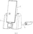
- FIG. 1is a perspective view of the invention
- FIG. 2is a front view of the invention
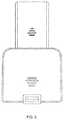
- FIG. 3is a rear view of the invention
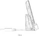
- FIG. 4is a left view of the invention
- FIG. 5is a perspective view of a sensor of the invention.
- FIG. 6is a perspective view of a mainframe of the invention.
- FIG. 7is a front view of the mainframe of the invention.
- FIG. 8is a top view of the mainframe of the invention.
- FIG. 9is a left view of the mainframe of the invention.
- FIG. 10is an exploded view of the sensor of the invention.
- FIG. 11is an exploded view of the mainframe of the invention.
- a wireless anti-theft mobile phone display standcomprises a mainframe 1 and a sensor 2 inserted into the mainframe through a slotted structure.
- an insertion opening 3 . 1is formed in the front face of the mainframe (as shown in FIG. 2 and FIG. 7 ) and is adapted to the sensor in shape
- slide grooves 3 . 2are formed in two sides of the insertion opening
- slide blocks 3 . 3 matched with the slide groovesare arranged on two sides of the sensor
- a lug boss 3 . 4 used for supporting the sensoris arranged at the bottom of the insertion opening.
- a mainframe mainboard 4 , a mainframe wireless-distance-measurement module 5 , a mainframe warner, a mainframe battery 23 , a Bluetooth module 14 , and a mainframe IR module (omitted in figures)are arranged in the mainframe, a power line 6 is arranged on the back face of the mainframe, a micro-switch 15 is arranged in the insertion opening of the mainframe, charging interfaces 7 and troughs 8 used for accommodating charging connectors of the sensor are formed in the lug boss of the mainframe, and mainframe fixing adhesives 17 are arranged at the bottom of the mainframe.
- the mainframe mainboardis connected to the mainframe wireless-distance-measurement module, the mainframe warner, the mainframe battery, the Bluetooth module, the mainframe IR module, the power line, the micro-switch, and the charging interfaces through wires.
- a mainframe shellis composed of a top shell 1 . 1 and a bottom plate 1 . 2 , the insertion opening is formed in the top shell, the lug boss is arranged on the top shell, and the mainframe fixing adhesives are attached to the bottom plate.
- the mainframe warneris a buzzer (omitted in the figures).
- the mainframe mainboardis further provided with an indicator light 22 , the top shell of the mainframe is provided with a light guide sheet 1 . 3 in cooperation with the indicator light which is used for displaying the operating state of the mainframe.
- a sensor mainboard 9 , a sensor wireless-distance-measurement module 24 , a sensor warner, a sensor battery 10 , and a sensor IR module (omitted in the figures)are arranged in the sensor, a mobile phone charging plug 11 and the charging connectors 12 are arranged at the bottom of the sensor, and an anti-dismantle switch 13 and a sample fixing adhesive 16 are arranged on the front face of the sensor (as shown in FIG. 2 ), and the mobile phone charging plug is connected to the sensor mainboard through a flexible wire 21 to be compatible with mobile phones having different sizes and thicknesses.
- the sensor mainboardis connected to the sensor wireless-distance-measurement module, the sensor warner, the sensor battery, the sensor IR module, the mobile phone charging plug, the charging connectors, and the anti-dismantle switch through wires.
- the sensor warnerincludes a buzzer (omitted in the figures) and a vibration motor 19 .
- a sensor shellis composed of a front cover 2 . 1 and a rear shell 2 . 2 , the anti-dismantle switch is arranged on the front cover, and a sensor fixing adhesive is attached to the front cover and has an opening 16 . 1 matched with the anti-dismantle switch.
- the mainframe IR module and the sensor IR module of CHQE-1.27are recommended to be used.
- the mainframe wireless-distance-measurement module and the sensor wireless-distance-measurement module of DWM1000are recommended to be used.
- a mobile phone fixing adhesive and the mainframe fixing adhesivesare 3M adhesives.
- the mainframeis affixed to a table surface through the mainframe fixing adhesives
- a mobile phoneis affixed to the sensor through the mobile phone fixing adhesive
- the mobile phone charging plug of the sensoris inserted into the charging port of the mobile phone
- the sensoris stored on the mainframe through the slotted structure.
- the charging connectors of the sensorinterface with the charging interfaces of the mainframe
- a customerdirectly pulls the sensor out of the mainframe when trying out the mobile phone and can try out the mobile phone freely within a certain range around the mainframe, and if the distance between the sensor and the mainframe exceeds a preset distance, the customer will be prompted by an alarm.
- An external power sourcesupplies power to the mainframe through the power line (the mainframe is powered by the mainframe battery during a power outage).
- the mainframesupplies power to the sensor (and charges the sensor battery at the same time) and charges the mobile phone through the sensor.
- the charging connectorsdisengage from the charging interfaces, and in this case, the sensor is powered by the sensor battery. All parts of the invention can be purchased to be obtained.
- the micro-switch on the mainframeWhen the mobile phone is tried out by the customer, the micro-switch on the mainframe will be triggered at the moment the sensor is inserted or pulled, and the main frame sends trial data (such as the taken-out times of the mobile phone) of the customer to the outside through the Bluetooth module to facilitate the data statistics and analysis of a background; an anti-dismantle switch on the sensor will be triggered to start the buzzer of the sensor to given an alarm when the mobile phone is separated from the sensor; the mainframe communicates with the sensor wireless-distance-measurement module and calculates the distance between the mainframe and the sensor; if the distance between the mainframe and the sensor is exceeds a preset safety distance, the sensor vibrates (the vibration motor in the sensor is started) first to remind the customer to pay attention to a trial distance, and if the distance between the mainframe and the sensor exceeds a preset warning distance (which is greater than the safety distance), the buzzers of the mainframe and the sensor are started to give alarms so as to
Landscapes
- Engineering & Computer Science (AREA)
- Signal Processing (AREA)
- Human Computer Interaction (AREA)
- Computer Networks & Wireless Communication (AREA)
- Physics & Mathematics (AREA)
- General Physics & Mathematics (AREA)
- Mobile Radio Communication Systems (AREA)
- Telephone Set Structure (AREA)
- Burglar Alarm Systems (AREA)
Abstract
Description
Claims (5)
Applications Claiming Priority (3)
| Application Number | Priority Date | Filing Date | Title |
|---|---|---|---|
| CN201920312573.6 | 2019-03-12 | ||
| CN201920312573.6UCN210114266U (en) | 2019-03-12 | 2019-03-12 | Wireless anti-theft display rack for mobile phone |
| CN201920312573U | 2019-03-12 |
Publications (2)
| Publication Number | Publication Date |
|---|---|
| US20200296195A1 US20200296195A1 (en) | 2020-09-17 |
| US10863011B2true US10863011B2 (en) | 2020-12-08 |
Family
ID=69611803
Family Applications (1)
| Application Number | Title | Priority Date | Filing Date |
|---|---|---|---|
| US16/748,932ActiveUS10863011B2 (en) | 2019-03-12 | 2020-01-22 | Wireless anti-theft mobile phone display stand |
Country Status (2)
| Country | Link |
|---|---|
| US (1) | US10863011B2 (en) |
| CN (1) | CN210114266U (en) |
Citations (12)
| Publication number | Priority date | Publication date | Assignee | Title |
|---|---|---|---|---|
| US6816713B2 (en)* | 2001-04-04 | 2004-11-09 | E-Lead Electronic Co., Ltd. | Switching and retaining device for use in cellular phones and peripheral communication equipment thereof |
| US20050107121A1 (en)* | 2003-11-18 | 2005-05-19 | Gamble Oliver W. | Method and system for enhance utilization of a cell phone |
| US7103760B1 (en)* | 2001-07-16 | 2006-09-05 | Billington Corey A | Embedded electronic device connectivity system |
| US20060229108A1 (en)* | 2005-02-04 | 2006-10-12 | Cehelnik Thomas G | Mobile phone extension and data interface via an audio headset connection |
| US7663502B2 (en)* | 1992-05-05 | 2010-02-16 | Intelligent Technologies International, Inc. | Asset system control arrangement and method |
| US20100317407A1 (en)* | 2009-06-16 | 2010-12-16 | Bran Ferren | Secondary display device |
| US20100323657A1 (en)* | 2007-07-24 | 2010-12-23 | Russell Brett Barnard | communication devices |
| US8035508B2 (en)* | 2002-06-11 | 2011-10-11 | Intelligent Technologies International, Inc. | Monitoring using cellular phones |
| US20130002110A1 (en)* | 2010-02-26 | 2013-01-03 | Nifco Inc. | Holding device |
| US20140089243A1 (en)* | 2012-01-08 | 2014-03-27 | Steven Charles Oppenheimer | System and Method For Item Self-Assessment As Being Extant or Displaced |
| US20140194161A1 (en)* | 2013-01-07 | 2014-07-10 | O2Micro Inc. | Apparatus for manipulating a mobile terminal device |
| US20160173970A1 (en)* | 2014-12-16 | 2016-06-16 | Clip & Talk Llc | Wireless Phone Accessory |
- 2019
- 2019-03-12CNCN201920312573.6Upatent/CN210114266U/enactiveActive
- 2020
- 2020-01-22USUS16/748,932patent/US10863011B2/enactiveActive
Patent Citations (12)
| Publication number | Priority date | Publication date | Assignee | Title |
|---|---|---|---|---|
| US7663502B2 (en)* | 1992-05-05 | 2010-02-16 | Intelligent Technologies International, Inc. | Asset system control arrangement and method |
| US6816713B2 (en)* | 2001-04-04 | 2004-11-09 | E-Lead Electronic Co., Ltd. | Switching and retaining device for use in cellular phones and peripheral communication equipment thereof |
| US7103760B1 (en)* | 2001-07-16 | 2006-09-05 | Billington Corey A | Embedded electronic device connectivity system |
| US8035508B2 (en)* | 2002-06-11 | 2011-10-11 | Intelligent Technologies International, Inc. | Monitoring using cellular phones |
| US20050107121A1 (en)* | 2003-11-18 | 2005-05-19 | Gamble Oliver W. | Method and system for enhance utilization of a cell phone |
| US20060229108A1 (en)* | 2005-02-04 | 2006-10-12 | Cehelnik Thomas G | Mobile phone extension and data interface via an audio headset connection |
| US20100323657A1 (en)* | 2007-07-24 | 2010-12-23 | Russell Brett Barnard | communication devices |
| US20100317407A1 (en)* | 2009-06-16 | 2010-12-16 | Bran Ferren | Secondary display device |
| US20130002110A1 (en)* | 2010-02-26 | 2013-01-03 | Nifco Inc. | Holding device |
| US20140089243A1 (en)* | 2012-01-08 | 2014-03-27 | Steven Charles Oppenheimer | System and Method For Item Self-Assessment As Being Extant or Displaced |
| US20140194161A1 (en)* | 2013-01-07 | 2014-07-10 | O2Micro Inc. | Apparatus for manipulating a mobile terminal device |
| US20160173970A1 (en)* | 2014-12-16 | 2016-06-16 | Clip & Talk Llc | Wireless Phone Accessory |
Also Published As
| Publication number | Publication date |
|---|---|
| CN210114266U (en) | 2020-02-28 |
| US20200296195A1 (en) | 2020-09-17 |
Similar Documents
| Publication | Publication Date | Title |
|---|---|---|
| US7209038B1 (en) | Security system for power and display of consumer electronic devices | |
| TWI222414B (en) | Handle stem and speed indicator | |
| US7724135B2 (en) | Coiled cable display device | |
| US8955807B2 (en) | Security bracket | |
| US8395907B2 (en) | Multi-sensor alarm apparatus, system and/or method for securing articles | |
| RU2017133606A (en) | SYSTEMS AND METHODS FOR PORTABLE DEVICES FOR DISTRIBUTING TABLETS | |
| US20040090773A1 (en) | Adaptable electric accessory system for containers, receptacles, and the like | |
| US20160073522A1 (en) | Shelf-mountable video display unit | |
| AU2008304229B2 (en) | Coiled cable display device | |
| WO2012069816A1 (en) | Electronic device display unit | |
| EP1339232A4 (en) | Monitor device, base device and information terminal device | |
| CN202998728U (en) | Multifunctional electronic product protection casing | |
| US10863011B2 (en) | Wireless anti-theft mobile phone display stand | |
| JP2013186795A (en) | Antitheft device for portable electronic apparatus | |
| CN206516015U (en) | Security system for protecting commodity | |
| CN212846810U (en) | Positioning display device | |
| CN211608954U (en) | Embedded display rack for commodity theft prevention | |
| CN210402033U (en) | Arrhythmia alarm watch | |
| CN219970110U (en) | Simple and convenient pad pasting instrument and pad pasting external member | |
| CN207067791U (en) | Diagnostic device | |
| US20250323517A1 (en) | Charging dock for vr device | |
| CN107463858B (en) | Touch all-in-one machine | |
| CN210245561U (en) | Battery casing assembly | |
| CN222149553U (en) | Display support of hand-held appliance | |
| CN218038207U (en) | Wireless anti-theft device |
Legal Events
| Date | Code | Title | Description |
|---|---|---|---|
| AS | Assignment | Owner name:ONTIME RFID TECHNOLOGY (CHANGXING) CO., LTD, CHINA Free format text:ASSIGNMENT OF ASSIGNORS INTEREST;ASSIGNOR:ZHUANG, XIAODONG;REEL/FRAME:051579/0826 Effective date:20191220 | |
| FEPP | Fee payment procedure | Free format text:ENTITY STATUS SET TO UNDISCOUNTED (ORIGINAL EVENT CODE: BIG.); ENTITY STATUS OF PATENT OWNER: SMALL ENTITY | |
| FEPP | Fee payment procedure | Free format text:ENTITY STATUS SET TO SMALL (ORIGINAL EVENT CODE: SMAL); ENTITY STATUS OF PATENT OWNER: SMALL ENTITY | |
| STPP | Information on status: patent application and granting procedure in general | Free format text:NOTICE OF ALLOWANCE MAILED -- APPLICATION RECEIVED IN OFFICE OF PUBLICATIONS | |
| STPP | Information on status: patent application and granting procedure in general | Free format text:PUBLICATIONS -- ISSUE FEE PAYMENT VERIFIED | |
| STCF | Information on status: patent grant | Free format text:PATENTED CASE | |
| MAFP | Maintenance fee payment | Free format text:PAYMENT OF MAINTENANCE FEE, 4TH YR, SMALL ENTITY (ORIGINAL EVENT CODE: M2551); ENTITY STATUS OF PATENT OWNER: SMALL ENTITY Year of fee payment:4 |