US10862753B2 - High availability for stateful services in public cloud logical networks - Google Patents
High availability for stateful services in public cloud logical networksDownload PDFInfo
- Publication number
- US10862753B2 US10862753B2US15/831,372US201715831372AUS10862753B2US 10862753 B2US10862753 B2US 10862753B2US 201715831372 AUS201715831372 AUS 201715831372AUS 10862753 B2US10862753 B2US 10862753B2
- Authority
- US
- United States
- Prior art keywords
- datacenter
- routing component
- network
- instance
- centralized routing
- Prior art date
- Legal status (The legal status is an assumption and is not a legal conclusion. Google has not performed a legal analysis and makes no representation as to the accuracy of the status listed.)
- Active
Links
Images


Classifications
- H—ELECTRICITY
- H04—ELECTRIC COMMUNICATION TECHNIQUE
- H04L—TRANSMISSION OF DIGITAL INFORMATION, e.g. TELEGRAPHIC COMMUNICATION
- H04L41/00—Arrangements for maintenance, administration or management of data switching networks, e.g. of packet switching networks
- H04L41/08—Configuration management of networks or network elements
- H04L41/0895—Configuration of virtualised networks or elements, e.g. virtualised network function or OpenFlow elements
- H—ELECTRICITY
- H04—ELECTRIC COMMUNICATION TECHNIQUE
- H04L—TRANSMISSION OF DIGITAL INFORMATION, e.g. TELEGRAPHIC COMMUNICATION
- H04L12/00—Data switching networks
- H04L12/02—Details
- H04L12/14—Charging, metering or billing arrangements for data wireline or wireless communications
- H04L12/1432—Metric aspects
- H04L12/1435—Metric aspects volume-based
- H—ELECTRICITY
- H04—ELECTRIC COMMUNICATION TECHNIQUE
- H04L—TRANSMISSION OF DIGITAL INFORMATION, e.g. TELEGRAPHIC COMMUNICATION
- H04L41/00—Arrangements for maintenance, administration or management of data switching networks, e.g. of packet switching networks
- H04L41/06—Management of faults, events, alarms or notifications
- H04L41/0654—Management of faults, events, alarms or notifications using network fault recovery
- H04L41/0663—Performing the actions predefined by failover planning, e.g. switching to standby network elements
- H—ELECTRICITY
- H04—ELECTRIC COMMUNICATION TECHNIQUE
- H04L—TRANSMISSION OF DIGITAL INFORMATION, e.g. TELEGRAPHIC COMMUNICATION
- H04L41/00—Arrangements for maintenance, administration or management of data switching networks, e.g. of packet switching networks
- H04L41/08—Configuration management of networks or network elements
- H04L41/0803—Configuration setting
- H04L41/0806—Configuration setting for initial configuration or provisioning, e.g. plug-and-play
- H—ELECTRICITY
- H04—ELECTRIC COMMUNICATION TECHNIQUE
- H04L—TRANSMISSION OF DIGITAL INFORMATION, e.g. TELEGRAPHIC COMMUNICATION
- H04L41/00—Arrangements for maintenance, administration or management of data switching networks, e.g. of packet switching networks
- H04L41/08—Configuration management of networks or network elements
- H04L41/0893—Assignment of logical groups to network elements
- H—ELECTRICITY
- H04—ELECTRIC COMMUNICATION TECHNIQUE
- H04L—TRANSMISSION OF DIGITAL INFORMATION, e.g. TELEGRAPHIC COMMUNICATION
- H04L41/00—Arrangements for maintenance, administration or management of data switching networks, e.g. of packet switching networks
- H04L41/12—Discovery or management of network topologies
- H—ELECTRICITY
- H04—ELECTRIC COMMUNICATION TECHNIQUE
- H04L—TRANSMISSION OF DIGITAL INFORMATION, e.g. TELEGRAPHIC COMMUNICATION
- H04L41/00—Arrangements for maintenance, administration or management of data switching networks, e.g. of packet switching networks
- H04L41/40—Arrangements for maintenance, administration or management of data switching networks, e.g. of packet switching networks using virtualisation of network functions or resources, e.g. SDN or NFV entities
- H—ELECTRICITY
- H04—ELECTRIC COMMUNICATION TECHNIQUE
- H04L—TRANSMISSION OF DIGITAL INFORMATION, e.g. TELEGRAPHIC COMMUNICATION
- H04L45/00—Routing or path finding of packets in data switching networks
- H04L45/02—Topology update or discovery
- H04L45/04—Interdomain routing, e.g. hierarchical routing
- H—ELECTRICITY
- H04—ELECTRIC COMMUNICATION TECHNIQUE
- H04L—TRANSMISSION OF DIGITAL INFORMATION, e.g. TELEGRAPHIC COMMUNICATION
- H04L45/00—Routing or path finding of packets in data switching networks
- H04L45/24—Multipath
- H04L45/247—Multipath using M:N active or standby paths
- H—ELECTRICITY
- H04—ELECTRIC COMMUNICATION TECHNIQUE
- H04L—TRANSMISSION OF DIGITAL INFORMATION, e.g. TELEGRAPHIC COMMUNICATION
- H04L45/00—Routing or path finding of packets in data switching networks
- H04L45/42—Centralised routing
- H—ELECTRICITY
- H04—ELECTRIC COMMUNICATION TECHNIQUE
- H04L—TRANSMISSION OF DIGITAL INFORMATION, e.g. TELEGRAPHIC COMMUNICATION
- H04L45/00—Routing or path finding of packets in data switching networks
- H04L45/58—Association of routers
- H04L45/586—Association of routers of virtual routers
- H—ELECTRICITY
- H04—ELECTRIC COMMUNICATION TECHNIQUE
- H04L—TRANSMISSION OF DIGITAL INFORMATION, e.g. TELEGRAPHIC COMMUNICATION
- H04L45/00—Routing or path finding of packets in data switching networks
- H04L45/64—Routing or path finding of packets in data switching networks using an overlay routing layer
- H—ELECTRICITY
- H04—ELECTRIC COMMUNICATION TECHNIQUE
- H04M—TELEPHONIC COMMUNICATION
- H04M15/00—Arrangements for metering, time-control or time indication ; Metering, charging or billing arrangements for voice wireline or wireless communications, e.g. VoIP
- H04M15/60—Arrangements for metering, time-control or time indication ; Metering, charging or billing arrangements for voice wireline or wireless communications, e.g. VoIP based on actual use of network resources
- H—ELECTRICITY
- H04—ELECTRIC COMMUNICATION TECHNIQUE
- H04M—TELEPHONIC COMMUNICATION
- H04M15/00—Arrangements for metering, time-control or time indication ; Metering, charging or billing arrangements for voice wireline or wireless communications, e.g. VoIP
- H04M15/80—Rating or billing plans; Tariff determination aspects
- H04M15/8033—Rating or billing plans; Tariff determination aspects location-dependent, e.g. business or home
- H—ELECTRICITY
- H04—ELECTRIC COMMUNICATION TECHNIQUE
- H04M—TELEPHONIC COMMUNICATION
- H04M15/00—Arrangements for metering, time-control or time indication ; Metering, charging or billing arrangements for voice wireline or wireless communications, e.g. VoIP
- H04M15/80—Rating or billing plans; Tariff determination aspects
- H04M15/8083—Rating or billing plans; Tariff determination aspects involving reduced rates or discounts, e.g. time-of-day reductions or volume discounts
- H—ELECTRICITY
- H04—ELECTRIC COMMUNICATION TECHNIQUE
- H04M—TELEPHONIC COMMUNICATION
- H04M15/00—Arrangements for metering, time-control or time indication ; Metering, charging or billing arrangements for voice wireline or wireless communications, e.g. VoIP
- H04M15/80—Rating or billing plans; Tariff determination aspects
- H04M15/8088—Rating or billing plans; Tariff determination aspects involving increased rates, e.g. spam messaging billing differentiation
- H—ELECTRICITY
- H04—ELECTRIC COMMUNICATION TECHNIQUE
- H04L—TRANSMISSION OF DIGITAL INFORMATION, e.g. TELEGRAPHIC COMMUNICATION
- H04L41/00—Arrangements for maintenance, administration or management of data switching networks, e.g. of packet switching networks
- H04L41/08—Configuration management of networks or network elements
- H04L41/0894—Policy-based network configuration management
- H—ELECTRICITY
- H04—ELECTRIC COMMUNICATION TECHNIQUE
- H04L—TRANSMISSION OF DIGITAL INFORMATION, e.g. TELEGRAPHIC COMMUNICATION
- H04L41/00—Arrangements for maintenance, administration or management of data switching networks, e.g. of packet switching networks
- H04L41/50—Network service management, e.g. ensuring proper service fulfilment according to agreements
- H04L41/508—Network service management, e.g. ensuring proper service fulfilment according to agreements based on type of value added network service under agreement
- H04L41/5096—Network service management, e.g. ensuring proper service fulfilment according to agreements based on type of value added network service under agreement wherein the managed service relates to distributed or central networked applications
Definitions
- a common datacenter setupincludes numerous servers that host virtual machines or other data compute nodes, with forwarding elements (e.g., software virtual switches) in the virtualization software of the server handling packet forwarding and network security for these data compute nodes.
- forwarding elementse.g., software virtual switches
- a private datacentere.g., an enterprise network
- technologyexists that allows the owner of the datacenter to control the hypervisors of the host servers and thereby implement their own security and packet forwarding rules.
- Public datacentersprovide companies with the ability to expand or move their networks out of their own private datacenters, thereby reducing the cost and other burdens of the physical servers and the regular upkeep required for them.
- at least a larger company networkwill be spread across multiple datacenters (e.g., multiple datacenters of a single public cloud provider).
- These public cloud providerstypically charge more for data traffic sent between datacenters than for data traffic sent within a datacenter, and therefore minimizing inter-datacenter traffic while maintaining the benefits of having multiple datacenters (e.g., protection in case of equipment or network failure) is a goal.
- Some embodimentsprovide a method for implementing high availability logical network gateways in a public multi-tenant cloud (e.g., one or more public multi-tenant datacenters).
- the logical network gatewaysprovide stateful services such as firewall, network address translation (NAT), load balancing, virtual private networking (VPN), etc. for data traffic between a logical network implemented at least partially in the public cloud and external entities (e.g., external client devices that communicate with the logical network).
- These logical network gatewaysare implemented in the public cloud in high availability pairs, with active gateways and standby gateways operating in different physical locations (e.g., different physical datacenters of the cloud).
- the stateful servicesare defined within a logical router that includes (northbound) logical interfaces for connection to the external network and (southbound) logical interfaces to which other logical forwarding elements of the logical network (e.g., logical switches) connect.
- a network control systeme.g., a management plane of a network control system that includes management plane and central control plane functions
- These centralized routing componentsare deployed in gateway appliances within the public cloud, which may operate within data compute nodes (DCNs) (e.g., virtual machines) hosted on public cloud host machines.
- DCNsdata compute nodes
- some embodimentsdefine a separate centralized routing component for each such physical location. These centralized routing components are then deployed in active-standby pairs. For a centralized routing component defined for a first physical location, the active instance is assigned to operate within a DCN in the first physical location while the standby instance operates within a DCN in a second physical location. These DCNs may implement multiple centralized routing components for different physical locations. For example, the DCN operating the active instance in the first physical location may also implement standby instances of centralized routing components for second, third, etc. physical locations.
- the forwarding elements implementing the logical networkare configured to send outgoing data messages to the centralized routing component for the particular physical location.
- the distributed routing component implemented by these forwarding elementsis configured to use a first route for northbound data messages specifying the active instance of the centralized routing component for the particular physical location as a next hop and a second route specifying the standby instance of the centralized routing component for the particular physical location as a next hop.
- the forwarding elementsare configured with the first route having a higher priority (e.g., priority X) and the second route having a slightly lower priority (e.g., priority X ⁇ 1) so that the second route will be used only if the active instance is not operational.
- the forwarding elements implementing the logical network within the public cloudoperate on the DCNs that connect to the logical network (e.g., the DCNs that run applications such as web servers, etc.). These DCNs also operate local controllers that configure the respective forwarding elements (i.e., a local controller on a DCN configures the forwarding element on the same DCN), and which receive configuration data from a gateway controller for the physical location.
- each physical location in the public cloudincludes a gateway controller that receives configuration instructions from a centralized control plane (e.g., operating in a private datacenter) and distributes the configuration instructions to the local controllers in the physical location. This gateway controller operates in the same DCN as the centralized routing component for the physical location in some embodiments (though may use a different network interface than the centralized routing component).
- the centralized routing componentsprovide stateful services for data traffic between the logical network DCNs and external entities. These external entities communicate with the logical network DCNs using a public network address (e.g., an IP address), while a cloud provider forwarding element converts this public network address into a network address of an interface of the DCN on which the centralized routing component operates.
- a public network addresse.g., an IP address
- a cloud provider forwarding elementconverts this public network address into a network address of an interface of the DCN on which the centralized routing component operates.
- the cloud providerrequires that the instances use different network addresses for their interfaces as the different physical locations use different subnets.
- the cloud providermaps the public network address to the network address of the active instance interface unless notified of a new mapping from the public network address to the network address of the standby instance interface (which occurs if the active instance fails).
- connection state from the active instancemay not be valid for the standby instance.
- stateful dataindicating that traffic from a particular external entity addressed to the active instance network address should be sent to a particular logical network DCN will not be valid because the active instance network address is not meaningful on the standby instance.
- the connection state datamay indicate existing connections (e.g., for a firewall that only allows outbound traffic if initiated by an incoming request, or vice versa), current NAT and/or load balancing rules, etc.).
- Each of the instances of the centralized routing componenti.e., the active instance and any standby instances
- the standby instancestores the equivalence between the active interface network address and its own interface network address.
- the standby instanceWhen the standby instance receives a set of connection state data from the active instance, the standby instance maps all of the occurrences of the active instance interface network address to its own interface network address before storing the connection state data. In addition, each instance maps the public network address in the stateful service rules to its own interface network address. Thus, when the standby instance begins receiving data traffic after a failure of the active instance, both its service rules as well as the current connection state will be in terms of its own interface network address.
- FIG. 1conceptually illustrates such a logical network of some embodiments.
- FIG. 2conceptually illustrates the physical implementation of the logical network of FIG. 1 across multiple physical locations of a public cloud in some embodiments.
- FIG. 3conceptually illustrates a network control system of some embodiments that manages forwarding elements in both a private datacenter and at least one public datacenter.
- FIG. 4conceptually illustrates a process of some embodiments for assigning active and standby SRs to gateway DCNs in different zones of a public cloud.
- FIG. 5conceptually illustrates the assignment of active and standby instances for SRs for a logical router of a logical network deployed across three public cloud zones.
- FIG. 6conceptually illustrates a process of some embodiments for processing outbound logical network data packets.
- FIG. 7conceptually illustrates the architecture of a gateway DCN of some embodiments.
- FIG. 8conceptually illustrates a process of some embodiments for receiving stateful service configuration rules, converting those rules to use a local IP address, and storing IP address equivalency mappings.
- FIG. 9conceptually illustrates gateway controllers at two different gateway DCNs receiving the same set of service configuration rules and replacing the public IP addresses with different local interface IP addresses.
- FIG. 10conceptually illustrates the IP address mappings stored by the gateway controllers of FIG. 9 in some embodiments.
- FIG. 11conceptually illustrates a process of some embodiments for modifying connection state by replacing a remote uplink IP address with a local uplink IP address.
- FIG. 12illustrates connection state data generated by an active SR instance being shared with a standby instance of the SR.
- FIG. 13conceptually illustrates an electronic system with which some embodiments of the invention are implemented.
- Some embodimentsprovide a method for implementing high availability logical network gateways in a public multi-tenant cloud (e.g., one or more public multi-tenant datacenters).
- the logical network gatewaysprovide stateful services such as firewall, network address translation (NAT), load balancing, virtual private networking (VPN), etc. for data traffic between a logical network implemented at least partially in the public cloud and external entities (e.g., external client devices that communicate with the logical network).
- These logical network gatewaysare implemented in the public cloud in high availability pairs, with active gateways and standby gateways operating in different physical locations (e.g., different physical datacenters of the cloud).
- the stateful servicesare defined within a logical router that includes (northbound) logical interfaces for connection to the external network and (southbound) logical interfaces to which other logical forwarding elements of the logical network (e.g., logical switches) connect.
- FIG. 1conceptually illustrates such a logical network 100 of some embodiments.
- the logical network 100is an abstraction of a network that is implemented in a distributed manner by multiple physical managed forwarding elements (which may be software forwarding elements, hardware forwarding elements, or a combination thereof).
- the logical network 100is configured by, e.g., a network administrator that defines the logical network through a network management tool or similar interface to a network control system.
- the logical network 100includes two logical switches 105 and 110 to which data compute nodes (DCNs) 125 - 140 logically connect via logical ports.
- the two logical switches 105 and 110also include logical ports that connect to a logical router 115 , for which one or more stateful services (e.g., firewall, NAT, load balancing, VPN, etc.) are configured.
- the logical router 115includes southbound logical ports to which the logical switches connect, as well as northbound uplink interfaces that connect the logical network 100 to an external network 120 (e.g., the Internet), allowing the DCNs of the logical network to exchange data traffic with external entities (e.g., client devices).
- an external network 120e.g., the Internet
- the network control systemdefines multiple routing components for the logical router 115 .
- some embodimentsdefine a distributed routing component (referred to herein as a distributed router, or DR) and one or more centralized routing components (referred to herein as service routers, or SRs).
- the DRis implemented in a distributed manner along with the logical switches, whereas the SRs are implemented in centralized logical network gateways.
- the SRsimplement both the connection to the external network and any stateful services defined for the logical router 115 . This enables the connection to external networks to be managed at a limited number of points, and also enables the use of stateful services (which are more difficult to distribute).
- the definition of a DR and SRs for logical routersis described in greater detail in U.S. Pat. No. 9,787,605, which is incorporated herein by reference.
- a logical network such as network 100may be implemented in a private datacenter in which the logical network administrator has control over the forwarding elements operating in virtualization software of the host machines (e.g., a typical enterprise datacenter) or, as in this invention, implemented in a public multi-tenant cloud.
- some embodimentsimplement logical networks across multiple physical locations (e.g., datacenters) of a public cloud. Using multiple datacenters may be done for redundancy purposes. For instance, a logical switch may have several redundant web servers connected, which are distributed across multiple datacenters in case of a problem at one of the datacenters.
- FIG. 2conceptually illustrates the physical implementation of the logical network 100 across multiple physical locations of a public cloud in some embodiments.
- the logical network 100is split across two zones 205 and 210 (e.g., different physical locations, such as different datacenters) of a public cloud.
- the public cloud providercharges higher fees for data traffic sent across zone boundaries than for data traffic sent within a zone.
- the zonesare separate for network address assignment purposes (i.e., the interfaces of DCNs in different zones must be on different subnets).
- the four DCNsoperate on hosts 215 - 218 , two of which are located in the first zone 205 and two of which are located in the second zone 210 . Because the tenant does not have access to control of the host virtualization software forwarding elements, these forwarding elements (not shown in the figure) do not implement the logical network. Instead, some embodiments operate managed forwarding elements (MFEs) 220 within the DCNs 125 - 140 , with applications (e.g., web server applications, etc.) also operating on the same DCNs.
- MFEsmanaged forwarding elements
- an applicationsends the packet to the MFE on its DCN, which performs logical network processing and sends the packet (via the forwarding elements managed by the cloud provider, possibly using an overlay network) to the destination DCN.
- the MFEs 220implement the two logical switches 105 and 110 as well as the DR of the logical router 115 .
- the implementation of the logical network within a public datacenteris described in further detail in U.S. patent application Ser. No. 15/367,157, now issued as U.S. Pat. No. 10,333,959, which is incorporated herein by reference.
- a SRis implemented in a gateway DCN operating on a host within each of the zones 205 and 210 .
- the host 225 in the first zone 205operates a gateway DCN 230
- a host 235 in the second zone 210operates a gateway DCN 240 .
- Each of these gateway DCNsexecutes at least one datapath implementing the logical network, including an SR (in addition to the distributed logical forwarding elements, such as the logical switches and DR).
- Some embodimentsdefine a separate SR for each of the zones 205 and 210 , so that the MFEs on hosts 215 and 216 preferentially send data traffic to the SR for zone 205 while the MFEs on hosts 217 and 218 preferentially send data traffic to the SR for zone 210 .
- some embodimentsoperate these SRs in high availability mode, with an active instance of the SR for a particular zone implemented on the gateway DCN in that zone and a standby instance of the SR for the particular zone implemented on the gateway DCN in a different zone.
- the SR for the first zone 205would have its active instance implemented on the gateway DCN 230 and its standby instance implemented on the gateway DCN 240
- the SR for the second zone 210would have its active instance implemented on the gateway DCN 240 and its standby instance implemented on the gateway DCN 230 .
- the MFEsand the gateway DCN datapaths are configured by a network control system that receives a logical network configuration, defines configuration data based on the logical network configuration, and distributes this configuration to the various forwarding elements that implement the logical network.
- FIG. 3conceptually illustrates such a network control system 300 of some embodiments that manages forwarding elements in both a private datacenter 305 and at least one public datacenter 310 .
- Both of the datacenters 305 and 310include host machines for hosting VMs or other DCNs.
- the network control systemhas the ability to manage the hypervisors (virtualization software), and therefore the forwarding elements that are part of those hypervisors.
- the network control systemdoes not have access to the hypervisors, as these are controlled by the owner of the datacenter.
- the network control system within the private datacenterincludes a management plane/central control plane (MP/CCP) cluster 315 and a local controller 320 on each of numerous host machines 325 .
- the local controller 320exercises direct control over a set of managed forwarding elements (MFEs) 330 on the host machine.
- MFEsmanaged forwarding elements
- VMsor other DCNs
- the MFE set 330Based on forwarding and configuration data received via the network control system, the MFE set 330 performs forwarding and network security (e.g., distributed firewall (DFW) rules, access control list (ACL) rules, etc.) operations on the data packets sent to and from these VMs.
- DFWdistributed firewall
- ACLaccess control list
- the MFE setmay be a single managed forwarding element (e.g., a single virtual switch that performs L2, L3, and additional processing) in some embodiments, or may be a combination of various managed forwarding and security elements (e.g., a set of filters, L2 switch(es), L3 router(s), etc. that all operate within the virtualization software).
- a single managed forwarding elemente.g., a single virtual switch that performs L2, L3, and additional processing
- various managed forwarding and security elementse.g., a set of filters, L2 switch(es), L3 router(s), etc. that all operate within the virtualization software.
- the MP/CCP cluster 315includes a management plane and central control plane with distinct features.
- the MP and CCPare separate applications that may operate on the same or different physical machines.
- the MP/CCP cluster 315 of some embodimentsmay include a single management plane application or a cluster of management plane applications, a single central control plane application or a cluster of central control plane applications, and any combination thereof.
- the management planeprovides application programming interfaces (APIs) through which administrators (e.g., via a cloud management application) of the private datacenter 305 enter configuration data to configure one or more logical networks to be implemented within the private datacenter 305 and/or one or more public datacenter(s).
- APIsapplication programming interfaces
- FIG. 1conceptually illustrates an example of such a logical network configuration.
- the logical network configuration datamay also include network address translation (NAT) rules, load balancing rules, rules for sending packets to third-party services, network security rules (e.g., DFW rules), etc.
- NATnetwork address translation
- DFW rulesnetwork security rules
- the management plane of some embodimentsconverts the logical network configuration into rules defining logical forwarding elements (e.g., logical switches & routers), logical ports for the logical forwarding elements, security and encryption rules for the logical ports, etc.
- the central control plane of some embodimentshandles the distribution of these rules to the appropriate MFEs (using, e.g., stored data indicating the location in the physical network of the DCN for each logical port).
- the central control planeUpon receiving a rule for a particular logical port and/or logical forwarding element, the central control plane identifies the span for that rule (i.e., the MFEs that need to receive the rule in order to properly implement the logical network) and distributes the rule to local controllers 320 that directly interact with the MFEs 330 on their respective host machines 325 .
- FIG. 3illustrates a virtual private cloud (VPC) 335 created for the owner of the private datacenter 305 (referred to herein as the tenant of the public datacenter).
- the virtual private cloud 335(or similar constructs) is a logically isolated set of resources of the public datacenter 310 over which the tenant has control.
- the tenantcan define a virtual network with network subnets and routing tables, and/or place their VMs into security groups (that are defined by the public cloud provider). However, the tenant does not have direct control over the forwarding elements in the cloud provider network. While this figure illustrates a single datacenter and single VPC, it should be understood that the network control system components will be replicated in other datacenters as well in some embodiments.
- the figureillustrates (i) a first host machine 340 that hosts a VM 345 with a gateway controller 350 and gateway datapath 380 and (ii) a set of additional host machines 355 that host VMs 360 with workload applications 365 .
- the host machines 340 and 355are shown as being part of the VPC, these host machines may also host additional VMs belonging to different VPCs (of the same or other tenants) in some embodiments.
- each of the host machines 340 and 355includes a forwarding element 370 .
- the host machinesinclude forwarding elements within their virtualization software that are managed by the public cloud provider.
- the network control system 300has no access to these forwarding elements, as they are part of the cloud provider network.
- the VM 345is a prepackaged machine image that includes a gateway controller 350 .
- the gateway controller 350receives data from the MP/CCP cluster 315 (e.g., from the central control plane application) for all of the logical ports implemented within the VPC 335 .
- the gateway controllerin the view of the MP/CCP cluster 315 , is equivalent to a local controller 320 with numerous logical ports connected (assuming there are numerous logical ports in the VPC 335 ).
- the MP/CCP cluster 315identifies the gateway controller 350 as a recipient for all of the configuration rules required for any of the logical ports in the VPC 335 .
- the gateway VM 345also operates a gateway datapath 380 for implementing one or more SRs for the logical network to provide centralized stateful services (e.g., NAT, load balancing, etc.) and for processing/routing packets sent between the VMs 360 and external sources (e.g., via the Internet).
- centralized stateful servicese.g., NAT, load balancing, etc.
- processing/routing packets sent between the VMs 360 and external sourcese.g., via the Internet.
- the gateway VM of some embodimentsis described in greater detail below by reference to FIG. 7 .
- the VMs 360are workload VMs, each of which runs a workload application 365 (e.g., a web server, application server, database server, etc.).
- a workload application 365e.g., a web server, application server, database server, etc.
- each of these VMsalso operates a control agent 370 and a managed forwarding element 375 (e.g., a virtual switch such as Open vSwitch).
- the gateway controller 350upon receiving a configuration rule, identifies the span of that rule within the VPC 335 (i.e., the various MFEs 375 that require the rule), and passes these configuration rules to the appropriate control agents 370 .
- the control agent 370uses this data to configure the MFE 375 to apply networking and/or security rules to packet sent to and from the workload application 365 , similar to how the local controller 320 configures the MFEs 330 .
- the SRs for each zone of a public cloudare deployed in active-standby pairs in some embodiments.
- the active instanceis assigned to operate within a gateway DCN in the first zone while the standby instance operates within a gateway DCN in a second zone.
- These DCNsmay implement multiple SRs for different physical locations.
- the DCN operating the active instance in the first physical locationmay also implement standby instances of centralized routing components for second, third, etc. physical locations.
- FIG. 4conceptually illustrates a process 400 of some embodiments for assigning active and standby SRs to gateway DCNs in different zones of a public cloud.
- the process 400is performed by the management plane (or a combined management plane and central control plane) of a network control system such as that shown in FIG. 3 .
- the process 400begins by receiving (at 405 ) a definition of a logical router that implements stateful services for a logical network with DCNs that operate (or will operate) in at least two zones of a public cloud.
- a definition of a logical routerthat implements stateful services for a logical network with DCNs that operate (or will operate) in at least two zones of a public cloud.
- some embodimentsdefine a single SR operating within that zone (possibly with active and standby instances both in the same zone).
- the management planereceives this logical router definition from an administrator through its APIs along with the configuration for other aspects of the logical network.
- the process 400selects (at 410 ) one of the public cloud zones at which the logical network is implemented. While the process 400 is illustrated as a serialized process in which the separate zones are treated one at a time, it should be understood that in some embodiments the operations 415 - 425 may be performed at least partly in parallel for the various zones. In addition, in some embodiments, a new zone may be added at a later time, in which case the operations 415 - 425 are performed when the zone is added.
- the process 400defines (at 415 ) an SR for the selected zone.
- This definitionincludes a definition of various stateful service rules, a routing table, etc.
- Some embodimentsdefine an uplink interface of the logical router for each public cloud zone that requires an SR, and thus define one SR for each uplink interface.
- each uplink interfacemay be assigned one or more public IP addresses by the public cloud provider, which is in charge of routing traffic for the public IP address to the SR.
- the process 400assigns (at 420 ) an active instance of the SR for the selected zone to a gateway DCN at the selected zone.
- the active gateway for a zoneis always preferentially located in that zone.
- the processalso assigns (at 425 ) a standby instance of the SR for the selected zone to a gateway DCN at a different zone.
- Some embodimentsdefine a single standby instance for each SR, while other embodiments define multiple standby instances for some or all SRs. For instance, a logical network deployed across three zones could have three SRs, each with one active and two standby instances.
- network addressese.g., IP addresses
- the process 400determines (at 425 ) whether additional zones at which the logical network is implemented remain. If this is the case, the process returns to 410 to define an SR and assign its active and standby instances for the next zone. Otherwise, the process 400 distributes (at 430 ) the SR configurations to the assigned gateway DCNs.
- the management planeprovides the various SR configurations and gateway DCN assignment to the central control plane, which distributes the appropriate configuration data to the gateway controllers at each zone.
- the gateway controllerswhich operate on the gateway DCNs in some embodiments, then configure the SR datapaths according to the received configurations.
- FIG. 5conceptually illustrates the assignment of active and standby instances for SRs for a logical router of a logical network deployed across three public cloud zones.
- This figureillustrates three gateway DCNs 505 - 515 , one operating in each zone (for simplicity, neither the other logical network DCNs nor the other modules executing on the gateway DCNs are shown in this figure).
- the gateway DCNsare described in greater detail below by reference to FIG. 7 .
- Each of the gateway DCNs 505 - 515executes an active instance of the SR for its own zone: the gateway DCN 505 in zone 1 executes the active instance 520 of the SR for zone 1, the gateway DCN 510 in zone 2 executes the active instance 525 of the SR for zone 2, and the gateway DCN 515 in zone 3 executes the active instance 530 of the SR for zone 3.
- each of the gateway DCNs 505 - 515executes a standby instance of the SR for a different zone: the gateway DCN 505 in zone 1 executes the standby instance 540 of the SR for zone 2, the gateway DCN 510 in zone 2 executes the standby instance 545 of the SR for zone 3, and the gateway DCN 515 in zone 3 executes the standby instance 535 of the SR for zone 1.
- each of the SR instancesis implemented within a datapath of the gateway DCN.
- Thismay be a datapath development kit (DPDK)-based datapath, a forwarding element such as Open vSwitch (OVS), or other datapath implementations.
- DPDKdatapath development kit
- OVSOpen vSwitch
- each SR datapathis attached to an uplink virtual network interface controller (VNIC) that is north-facing (i.e., for receiving communications from external networks) and a local overlay VNIC that is south-facing (i.e., for receiving communications from logical network DCNs).
- VNICvirtual network interface controller
- Each of these VNICshas a different IP address in some embodiments.
- each of the datapathsalso executes the other logical forwarding elements of the logical network (e.g., the DR and any logical switches).
- the logical networke.g., the DR and any logical switches.
- incoming (southbound) data packetsare processed through the SR as well as the DR and appropriate logical switch at the gateway DCN (for outgoing traffic, the majority of the logical processing occurs at the MFE operating on the source DCN).
- a single datapathexecutes on each gateway DCN. Multiple local overlay VNICs and uplink VNICs each connect to this single datapath in this case, which executes the correct SR according to the VNIC on which the packet is received (possibly in addition to other rules).
- the MFEs that operate in the DCNs in a particular zone to implement the logical switches and DRare configured in some embodiments to send outgoing data messages to the SR for the particular zone.
- the DR implemented by these forwarding elementsis configured to use a first route for northbound data messages specifying the active instance of the SR for the particular zone as a next hop and a second route specifying the standby instance of the SR for the particular zone as a next hop.
- the forwarding elementsare configured with the first route having a higher priority (e.g., priority X) and the second route having a slightly lower priority (e.g., priority X ⁇ 1) so that the second route will be used only if the active instance is not operational.
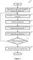
- FIG. 6conceptually illustrates a process 600 of some embodiments for processing outbound logical network data packets.
- the process 600in some embodiments, is performed by an MFE executing on a logical network DCN that resides in a public cloud (e.g., one of the MFEs 220 of FIG. 2 ).
- the logical networkis implemented across at least two zones of the public cloud, and includes a logical router with active and standby SRs for each zone.
- the process 600begins by receiving (at 605 ) a packet at the MFE from an application on the same DCN as the MFE.
- the applicationsends the packet to the MFE via an internal port of the MFE, as described in greater detail in U.S. patent application Ser. No. 15/367,157, which is incorporated by reference above.
- the processperforms (at 610 ) logical processing on the packet to determine that the packet needs to be sent to the SR.
- Thismay include performing logical switch processing to determine that the packet should be processed by the DR, and then performing logical routing for the DR, at which point the MFE determines to send the packet to the SR (e.g., using a default route that routes outgoing traffic (to non-logical network IP addresses) to the SR).
- other security processese.g., distributed firewall operations are applied to the packet.
- the processdetermines (at 615 ) whether the active SR for the zone is operational (i.e., the active SR located in the same zone as the MFE).
- the MFEtrades regular keep-alive signals (e.g., using bidirectional forwarding detection (BFD)) with the gateways hosting both the active and standby SRs (or just the gateway hosting the active SR) to ensure that the active SR is operational, and flags the route to an SR to not be used if the gateway hosting the SR is down.
- BFDbidirectional forwarding detection
- the process 600sends (at 620 ) the packet to the active SR instance based on its higher priority route.
- the processsends (at 625 ) the packet to a standby SR instance based on its lower priority route.
- the MFEencapsulates the packet using an IP address assigned to the DCN on which the MFE operates by the cloud provider (which may be different from the logical network IP address used by the application that initially sent the packet).
- the MFEdoes not make a specific decision to send the packet to the SR separate from the decision as to whether the active SR is operational. Instead, the MFE performs DR processing to route the packet, which results in a decision to send the packet to the active instance of the SR if that instance is operational and a decision to send the packet to the standby instance of the SR if the active instance is not operational.
- the MFEs operating on the logical network DCNs within the public cloud to implement the logical networkare configured by local controllers that receive configuration data from a gateway controller.
- each physical location (e.g., each zone) in the public cloud in which the logical network is implementedincludes a gateway controller that receives configuration instructions from a centralized control plane (e.g., operating in a private datacenter) and distributes the configuration instructions to the local controllers in the zone.
- This gateway controlleroperates on the same DCN as the SR for the zone in some embodiments (though may use a different network interface than the centralized routing component).
- FIG. 7conceptually illustrates the architecture of such a gateway DCN 700 of some embodiments.
- the gateway DCNis packaged as a pre-configured VM image (e.g., an Amazon Machine Image) for a specific cloud provider that the administrator of the logical network can instantiate as one of the DCN in the public cloud.
- the gateway DCN 700includes a gateway controller 705 , a public cloud manager (PCM) 710 , and a gateway datapath 715 .
- gateway DCNsmay include different combinations of these modules as well all or some of these modules along with other modules.
- the gateway DCNmay also include a distributed network encryption manager for handling the distribution of encryption keys and/or a DHCP module that acts as a DHCP server for the DCNs operating within the zone.
- the gateway DCNincludes three interfaces—a control VNIC 730 , an uplink VNIC 735 , and a local overlay VNIC 740 .
- the control VNIC 730is used only for control path communications between the local agents on the other hosts in the VPC and the gateway controller 705 , and between the MP/CCP cluster and the gateway controller 705 (as well as any communication for the PCM).
- the uplink VNIC 735handles north-south packets sent from the gateway datapath 715 towards external destinations (and received from those external destinations), which will generally not be encapsulated by the datapath.
- the local overlay VNIC 740handles east-west data packets that the gateway datapath processes to send packets between workload applications within its zone and DCNs in other zones of the public cloud, other public clouds, and/or an on-premises private datacenter.
- the gateway controller 705 of some embodimentsperforms the controller functions to receive data from the centralized MP/CCP and distribute that data to the appropriate DCNs within the public cloud zone.
- a CCP interface 745 of the gateway controller 705receives configuration rules from the central controller and provides information back to the central controller (e.g., when a new VM is created within the zone and thus a new logical port needs to be associated with the gateway).
- the agent interface 750distributes configuration data to the local agents operating on DCNs in the VPC and receives updates from these local agents when events occur on the DCN (e.g., the creation of an interface on the DCN, etc.). In some embodiments, both of these interfaces 745 and 750 are part of a netcap agent operating on the gateway DCN.
- the gateway controller 705also includes a span manager 755 and a local overlay manager 760 .
- the span managerreceives configuration rules sent from the central controller (via the CCP interface 745 ), determines the MFEs executing on DCNs within the public cloud zone (including, possibly the gateway datapath 715 ) that require these configuration rules, and sends these configuration rules to the appropriate agents in the zone. Some embodiments use different adapters and/or different queues for each agent within the zone, placing each received rule into one or more such queues.
- the local overlay manager 760handles the management of the overlay network within the zone. Assuming the MFEs in the zone are using an overlay, each agent on a DCN in the zone (and the gateway datapath 715 ) provides its VTEP IP address and MAC address bound to that VTEP IP address to the gateway controller 705 in some embodiments. The local overlay manager 760 of some embodiments identifies which MFEs in the zone require each provided binding, and handles the provision of this information to the MFEs in the zone so that data packets sent to the MAC address can be encapsulated using the corresponding VTEP IP address.
- a first MFErequires the MAC:VTEP IP binding of a second MFE if there is the possibility of the workload application attached to the first MFE sending a data packet to the workload application attached to the second MFE without the data packet being required to travel through the gateway datapath 715 .
- the public cloud manager (PCM) 710 of some embodimentsenables the network control system to interact with the compute management system of the public cloud provider.
- the PCM of some embodimentsuses public cloud APIs to retrieve inventory, configuration, status, and statistics information from the public cloud provider.
- the PCMmay operate in the MP/CCP cluster (e.g., in the private datacenter).
- the PCMincludes public cloud APIs 765 and interfaces 770 and 775 for communicating with the agent and with the MP/CCP cluster.
- the PCMonly communicates directly with the management plane, and any communications to and from the agents pass through the gateway controller.
- the public cloud APIs 765are used to communicate with the public cloud compute manager.
- the gateway datapath 715implements one or more SRs in some embodiments to handle packet processing for at least data packets between data compute nodes within its local zone and sources/destinations external to the logical network (e.g., clients accessing the data compute nodes through the Internet).
- the gateway datapathimplements SRs not only for the local zone but also for other cloud provider zones (e.g., as standby SR instances).
- the datapath 715shows a SR 780 within the datapath, but it should be understood that the datapath may also include configuration for one or more logical switches and one or more DRs of the logical network.
- the datapath 715may be a datapath development kit (DPDK)-based datapath, an OVS datapath, or another type of datapath that can be implemented within a DCN.
- DPDKdatapath development kit
- OVS datapathsome embodiments use the OVS datapath for the logical switch and/or distributed router processing, while implementing a separate namespace to handle the centralized routing component processing.
- DPDK-based datapathimplement the configuration for all of the logical forwarding element components within the same datapath. Additional description of the gateway datapath of some embodiments is described in U.S. Patent Publication 2016/0226759, which is incorporated herein by reference.
- the datapath 715uses two ports, a VTEP port 785 and an uplink port 790 , which connect to the local overlay VNIC 740 and uplink VNIC 735 respectively.
- the gateway datapath 715receives packets sent from local workloads in its zone via the VTEP 785 , which uses an IP address assigned by the cloud provider on a local subnet (i.e., on the same subnet as the addresses assigned to the other logical network DCNs in the zone).
- This VTEP port 785is also used for packets sent to and from DCNs in other public cloud zones or in a private datacenter, as all of this traffic is encapsulated for the logical network in some embodiments.
- the uplink port 790is used by the datapath 715 to send and receive north-south data traffic between the workloads in the VPC and external sources/destinations. These data packets are sent out of the uplink port without encapsulation (though they may be tunneled separately on the cloud provider network to a cloud provider gateway). In addition, these packets (both incoming and outgoing) may require centralized services that are configured for the SR, such as NAT, firewall rules for north-south traffic, service chaining, load balancing, etc.
- the SRsprovide stateful services for data traffic between the logical network DCNs and external entities. These external entities communicate with the logical network DCNs using a public network address (e.g., an IP address), while a cloud provider forwarding element converts this public network address into a network address of an interface of the DCN on which the SR operates (i.e., the uplink VNIC 735 ).
- a public network addresse.g., an IP address
- a cloud provider forwarding elementconverts this public network address into a network address of an interface of the DCN on which the SR operates (i.e., the uplink VNIC 735 ).
- the cloud providerrequires that the instances use different network addresses for their interfaces as the different physical locations use different subnets.
- the cloud provider gatewaymaps the public network address to the network address of the active instance interface unless notified of a new mapping from the public network address to the network address of the standby instance interface (which occurs if the active instance fails).
- the MP/CCPprovides the gateway controller with various configuration rules for each service, to both the active instance for an SR and any standby instances.
- the active SR instanceWhile processing packets, stores connection state that is used to inform decisions about future packets (e.g., noting when a connection has been validly opened, storing load balancing decisions for connections so that future southbound packets for the connection will be routed to the correct DCN, etc.
- the active SR instancefails and subsequent north-south data traffic will be processed by the standby SR instance, the active instance regularly shares its connection state with the standby instance.
- these two instanceshave different network addresses, so the connection state from the active instance may not be valid for the standby instance. For instance, stateful data indicating that traffic from a particular external entity addressed to the active instance network address should be sent to a particular logical network DCN will not be valid because the active instance network address is not meaningful on the standby instance.
- Each of the instances of the centralized routing componenti.e., the active instance and any standby instances
- the standby instancestores the equivalence between the active interface network address and its own interface network address.
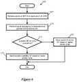
- FIG. 8conceptually illustrates a process 800 of some embodiments for receiving stateful service configuration rules, converting those rules to use a local IP address, and storing IP address equivalency mappings.
- the process 800is performed by a gateway controller operating on a gateway DCN in a public cloud zone, such as the gateway DCN 700 .
- the gateway controllerreceives configuration data from a central controller, and uses this data to configure the datapath operating on the same gateway DCN.
- the process 800will be described in part by reference to FIGS. 9 and 10 .
- the process 800 of some embodimentsbegins by receiving (at 805 ) configuration data that includes a set of service rules for an SR that use a public IP address.
- the gateway DCNmay implement an active instance or a standby instance of the SR, as the operations performed in this process are the same in either case.
- the public IP addressis associated with both the active and standby instances of the SR, with the cloud provider (e.g., a gateway of the cloud provider) receiving these packets, performing address translation, and forwarding them to the correct gateway DCN using the IP address of an interface of the gateway DCN datapath (e.g., the uplink VNIC IP address).
- the cloud providere.g., a gateway of the cloud provider
- the service rulesrather than being written in terms of the uplink interface IP address that changes between the different instances of the SR, instead use the public IP address.
- These service rulesmay include NAT rules, load balancing rules, firewall rules, etc.
- an SRmay be associated with multiple public IP addresses, with different services using different IP addresses (and thus different interface IP addresses as well).
- the process 800also determines (at 810 ) a local uplink interface IP address that maps to the public IP address, and stores (at 815 ) this mapping between the public IP and the local interface IP. In some embodiments, this mapping is also received as configuration data from the central controller. In other embodiments, the public cloud management system stores this information and the public cloud manager of the gateway DCN interacts with the public cloud management system to learn the mapping information.
- the process 800replaces (at 820 ) the public IP address with the local uplink interface IP address that maps to the public IP address in the set of service rules.
- the gateway controller for an active instance of an SRwill use a first uplink interface IP address in the set of rules and the gateway controller for a standby instance of the same SR will use a second, different uplink interface IP address in the same set of rules.
- the uplink IP addresswill be the actual address used for incoming (southbound) packets received by the SR, whereas the public IP address will have been replaced in these packets and thus would not be useful for the service rules.
- the process 800then configures (at 825 ) the datapath to use the set of service rules with the uplink interface IP address.
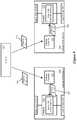
- FIG. 9conceptually illustrates gateway controllers at two different gateway DCNs receiving the same set of service configuration rules and replacing the public IP addresses with different local interface IP addresses.
- This figureillustrates two gateway DCNs 905 and 910 and a central controller (MP/CCP) 915 .
- the MP/CCP 915performs management plane and/or central control plane functions, and operates in a private datacenter in some embodiments.
- the first gateway DCN 905is located in a first zone of a public cloud, while the second gateway DCN 910 is located in a second zone of the public cloud.
- the first gateway DCN 905includes a gateway controller 920 and a datapath 925 that implements an active instance of the SR for the first zone, while the second gateway DCN 910 includes a gateway controller 930 and a datapath 935 that implements a standby instance of the SR for the first zone.
- the datapath 925uses an uplink VNIC with an IP address of S1
- the datapath 935uses an uplink VNIC with an IP address of S2.
- S1 and S2are in different IP subnets owing to being located in different zones of the public cloud.
- the MP/CCPprovides a set of configuration rules 940 to the gateway controllers 920 and 930 .
- This set of configuration rules(which is the same for both gateway controllers) uses a public IP address E1.
- the gateway controller 920receives this set of rules 940 and modifies the rules to replace instances of the public IP address E1 with the local uplink IP address S1.
- the gateway controller 920uses this modified set of rules 945 to configure the datapath 925 to implement the stateful service to which the rules relate.
- the gateway controller 930receives the set of rules 940 and modifies the rules to replace instances of the public IP address E1 with the local uplink IP address S2.
- the gateway controller 930uses this modified set of rules 950 to configure the datapath 935 to implement the stateful service to which the rules relate.
- Examples of such stateful service rulescould include a pair of NAT rules (for incoming and outgoing packets) that translate any packet with a destination IP address E1 to a private (logical network) address L1 (for incoming packets) and any packet with a source IP address L1 to the public IP address E1 (for outgoing packets).
- the gateway controllersUpon receiving these rules, the gateway controllers would modify them so that the first gateway datapath 925 would translate the destination IP address S1 to L1 for incoming packets and source IP address L1 to S1 for outgoing packets, while the second gateway datapath 935 would translate the destination IP address S2 to L1 for incoming packets and source IP address L1 to S2 for outgoing packets.
- the process 800also determines (at 830 ) the uplink IP addresses of the other SR instances that map to the same public IP address, and stores (at 835 ) the mapping of equivalent uplink IP addresses.
- the process 800then ends.
- the gateway controller 920would identify S2 as another uplink IP address that also maps to public IP address E1. If there are numerous standby SRs, then all of the several equivalent IP addresses will be mapped together.
- each SRmay use multiple public IP addresses that are each mapped to different uplink IP addresses, and separate equivalency mappings are stored for each.
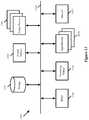
- FIG. 10conceptually illustrates the IP address mappings stored by the gateway controllers 920 and 930 in some embodiments.
- Each of the gateway controllersstores two sets of mappings: a first set mapping public IP addresses to local uplink IP addresses, and a set of set mapping local uplink IP addresses to equivalent uplink IP addresses used at other instances of the same SR.
- the controllermay store mappings for multiple SRs implemented by the datapath on the gateway DCN as well as for multiple public IP addresses used by the same SR.
- each of the gateway controllersstores data about two public IP addresses E1 and E2, which may both be related to the same SR (for zone 1) or related to two different SRs (e.g., the zone 1 SR and the zone 2 SR).
- the first gateway controller 920stores mappings 1005 of the public IP address E1 to its local uplink IP address S1 and of the public IP address E2 to its local uplink IP address S3.
- the second gateway controller 930stores mappings 1010 of the public IP address E1 to its local uplink IP address S2 and of the public IP address E2 to its local uplink IP address S4.
- the first gateway controller 920stores mappings 1015 of the equivalency between its local uplink IP address S1 and the remote uplink IP address S2 as well as between its local uplink IP address S3 and the remote uplink IP address S4.
- the second gateway controller 930stores mappings 1020 of the equivalency between its local uplink IP address S2 and the remote uplink IP address S1 as well as between its local uplink IP address S4 and the remote uplink IP address S3.
- an active SR instancegenerates connection state data (e.g., existing connections that the firewall has allowed, current load balancing decisions for various connections, etc.) while processing packets.
- the active SR instance(or the gateway controller for the active SR instance) regularly (e.g., at timed intervals, whenever the connection state has been updated, etc.) shares this connection state with any of its standby SR instances (or the gateway controllers for these standby SR instances) in other public cloud zones.
- the standby SR instanceswill have the data stored in case the active instance fails and one of the standby instances becomes active, at which point the DCNs that previously sent northbound traffic to the active SR instance for their zone will send this traffic to standby (now active) SR instance and the public cloud provider gateway will send traffic for the public IP address(es) associated with the SR to the standby (now active) SR instance.
- the gateway controller for a standby SR instanceWhen the gateway controller for a standby SR instance receives a set of connection state data from the active SR instance, the gateway controller maps all of the occurrences of the active instance uplink IP address to its own equivalent uplink IP address before providing the connection state data to the datapath for use by the SR.
- the standby instancebegins receiving data traffic after a failure of the active instance, both its service rules as well as the current connection state use its own uplink IP address.
- FIG. 11conceptually illustrates a process 1100 of some embodiments for modifying connection state by replacing a remote uplink IP address with a local uplink IP address.
- the process 1100is performed by a gateway controller operating on the same DCN as the datapath that implements a standby instance of an SR.
- the gateway controllerperforms the process 1100 each time connection state data is received from the active instance of the SR.
- the process 1100will be described in part by reference to FIG. 12 , which illustrates connection state data generated by an active SR instance being shared with a standby instance of the SR.
- the process 1100begins by receiving (at 1105 ) connection state data from the active SR instance at the standby SR instance (or at the gateway controller executing on the same DCN as the standby SR instance).
- the gateway controller for the active SR instanceretrieves this data from the datapath implementing the active SR instance regularly, and sends this data (either directly or through the management plane or central control plane) to the gateway controllers for the standby instances of the SR.
- FIG. 12illustrates the gateway DCNs 905 and 910 of FIG. 9 , with the datapath 925 at the first gateway DCN 905 implementing the active SR instance and the datapath 935 at the second gateway DCN 910 implementing a standby SR instance.
- the gateway controller 920 on the first DCN 905provides connection state data 1200 to the gateway controller 930 . This state uses the uplink IP address S1 associated with the active SR instance.
- the process 1100determines (at 1110 ) the mapping of the active instance uplink IP address to a local uplink IP address. As shown in FIG. 10 , these mappings are stored by the gateway controller in some embodiments based on data received from the MP/CCP and/or the cloud provider management system.
- the process 1100then replaces (at 1115 ) the active instance uplink IP address with the equivalent local uplink IP address in the received connection state data, and provides (at 825 ) the modified connection state data with the local uplink IP address to the datapath for storage (e.g., in a cache of the datapath).
- the datapathstores this data as though it was self-generated, for use in case the active SR fails and data traffic for the SR is directed to the standby instance.
- FIG. 12illustrates that the gateway controller 930 has modified the connection state data to use the local uplink IP address S2 and provides this modified connection state data 1205 to the datapath 935 .
- FIG. 13conceptually illustrates an electronic system 1300 with which some embodiments of the invention are implemented.
- the electronic system 1300can be used to execute any of the control, virtualization, or operating system applications described above.
- the electronic system 1300may be a computer (e.g., a desktop computer, personal computer, tablet computer, server computer, mainframe, a blade computer etc.), phone, PDA, or any other sort of electronic device.
- Such an electronic systemincludes various types of computer readable media and interfaces for various other types of computer readable media.
- Electronic system 1300includes a bus 1305 , processing unit(s) 1310 , a system memory 1325 , a read-only memory 1330 , a permanent storage device 1335 , input devices 1340 , and output devices 1345 .
- the bus 1305collectively represents all system, peripheral, and chipset buses that communicatively connect the numerous internal devices of the electronic system 1300 .
- the bus 1305communicatively connects the processing unit(s) 1310 with the read-only memory 1330 , the system memory 1325 , and the permanent storage device 1335 .
- the processing unit(s) 1310retrieve instructions to execute and data to process in order to execute the processes of the invention.
- the processing unit(s)may be a single processor or a multi-core processor in different embodiments.
- the read-only-memory (ROM) 1330stores static data and instructions that are needed by the processing unit(s) 1310 and other modules of the electronic system.
- the permanent storage device 1335is a read-and-write memory device. This device is a non-volatile memory unit that stores instructions and data even when the electronic system 1300 is off. Some embodiments of the invention use a mass-storage device (such as a magnetic or optical disk and its corresponding disk drive) as the permanent storage device 1335 .
- the system memory 1325is a read-and-write memory device. However, unlike storage device 1335 , the system memory is a volatile read-and-write memory, such a random-access memory.
- the system memorystores some of the instructions and data that the processor needs at runtime.
- the invention's processesare stored in the system memory 1325 , the permanent storage device 1335 , and/or the read-only memory 1330 . From these various memory units, the processing unit(s) 1310 retrieve instructions to execute and data to process in order to execute the processes of some embodiments.
- the bus 1305also connects to the input and output devices 1340 and 1345 .
- the input devicesenable the user to communicate information and select commands to the electronic system.
- the input devices 1340include alphanumeric keyboards and pointing devices (also called “cursor control devices”).
- the output devices 1345display images generated by the electronic system.
- the output devicesinclude printers and display devices, such as cathode ray tubes (CRT) or liquid crystal displays (LCD). Some embodiments include devices such as a touchscreen that function as both input and output devices.
- bus 1305also couples electronic system 1300 to a network 1365 through a network adapter (not shown).
- the computercan be a part of a network of computers (such as a local area network (“LAN”), a wide area network (“WAN”), or an Intranet, or a network of networks, such as the Internet. Any or all components of electronic system 1300 may be used in conjunction with the invention.
- Some embodimentsinclude electronic components, such as microprocessors, storage and memory that store computer program instructions in a machine-readable or computer-readable medium (alternatively referred to as computer-readable storage media, machine-readable media, or machine-readable storage media).
- computer-readable mediainclude RAM, ROM, read-only compact discs (CD-ROM), recordable compact discs (CD-R), rewritable compact discs (CD-RW), read-only digital versatile discs (e.g., DVD-ROM, dual-layer DVD-ROM), a variety of recordable/rewritable DVDs (e.g., DVD-RAM, DVD-RW, DVD+RW, etc.), flash memory (e.g., SD cards, mini-SD cards, micro-SD cards, etc.), magnetic and/or solid state hard drives, read-only and recordable Blu-Ray® discs, ultra-density optical discs, any other optical or magnetic media, and floppy disks.
- CD-ROMcompact discs
- CD-Rrecordable compact
- the computer-readable mediamay store a computer program that is executable by at least one processing unit and includes sets of instructions for performing various operations.
- Examples of computer programs or computer codeinclude machine code, such as is produced by a compiler, and files including higher-level code that are executed by a computer, an electronic component, or a microprocessor using an interpreter.
- ASICsapplication specific integrated circuits
- FPGAsfield programmable gate arrays
- integrated circuitsexecute instructions that are stored on the circuit itself.
- the terms “computer”, “server”, “processor”, and “memory”all refer to electronic or other technological devices. These terms exclude people or groups of people.
- display or displayingmeans displaying on an electronic device.
- the terms “computer readable medium,” “computer readable media,” and “machine readable medium”are entirely restricted to tangible, physical objects that store information in a form that is readable by a computer. These terms exclude any wireless signals, wired download signals, and any other ephemeral signals.
- DCNsdata compute nodes
- addressable nodesmay include non-virtualized physical hosts, virtual machines, containers that run on top of a host operating system without the need for a hypervisor or separate operating system, and hypervisor kernel network interface modules.
- VMsin some embodiments, operate with their own guest operating systems on a host using resources of the host virtualized by virtualization software (e.g., a hypervisor, virtual machine monitor, etc.).
- the tenanti.e., the owner of the VM
- Some containersare constructs that run on top of a host operating system without the need for a hypervisor or separate guest operating system.
- the host operating systemuses name spaces to isolate the containers from each other and therefore provides operating-system level segregation of the different groups of applications that operate within different containers.
- This segregationis akin to the VM segregation that is offered in hypervisor-virtualized environments that virtualize system hardware, and thus can be viewed as a form of virtualization that isolates different groups of applications that operate in different containers.
- Such containersare more lightweight than VMs.
- Hypervisor kernel network interface modulesin some embodiments, is a non-VM DCN that includes a network stack with a hypervisor kernel network interface and receive/transmit threads.
- a hypervisor kernel network interface moduleis the vmknic module that is part of the ESXiTM hypervisor of VMware, Inc.
- VMsvirtual machines
- examples givencould be any type of DCNs, including physical hosts, VMs, non-VM containers, and hypervisor kernel network interface modules.
- the example networkscould include combinations of different types of DCNs in some embodiments.
- FIGS. 4, 6, 8 and 11conceptually illustrate processes.
- the specific operations of these processesmay not be performed in the exact order shown and described.
- the specific operationsmay not be performed in one continuous series of operations, and different specific operations may be performed in different embodiments.
- the processcould be implemented using several sub-processes, or as part of a larger macro process.
- the inventionis not to be limited by the foregoing illustrative details, but rather is to be defined by the appended claims.
Landscapes
- Engineering & Computer Science (AREA)
- Computer Networks & Wireless Communication (AREA)
- Signal Processing (AREA)
- Business, Economics & Management (AREA)
- General Business, Economics & Management (AREA)
- Data Exchanges In Wide-Area Networks (AREA)
Abstract
Description
Claims (22)
Priority Applications (5)
| Application Number | Priority Date | Filing Date | Title |
|---|---|---|---|
| US15/831,372US10862753B2 (en) | 2017-12-04 | 2017-12-04 | High availability for stateful services in public cloud logical networks |
| CN201880058548.8ACN111095880B (en) | 2017-12-04 | 2018-10-23 | Method, apparatus, system and readable medium for public cloud logical network |
| EP18830019.8AEP3669504B1 (en) | 2017-12-04 | 2018-10-23 | High availability for stateful services in public cloud logical networks |
| PCT/US2018/057186WO2019112704A1 (en) | 2017-12-04 | 2018-10-23 | High availability for stateful services in public cloud logical networks |
| EP22209709.9AEP4164196B1 (en) | 2017-12-04 | 2018-10-23 | High availability for stateful services in public cloud logical networks |
Applications Claiming Priority (1)
| Application Number | Priority Date | Filing Date | Title |
|---|---|---|---|
| US15/831,372US10862753B2 (en) | 2017-12-04 | 2017-12-04 | High availability for stateful services in public cloud logical networks |
Publications (2)
| Publication Number | Publication Date |
|---|---|
| US20190173757A1 US20190173757A1 (en) | 2019-06-06 |
| US10862753B2true US10862753B2 (en) | 2020-12-08 |
Family
ID=66657678
Family Applications (1)
| Application Number | Title | Priority Date | Filing Date |
|---|---|---|---|
| US15/831,372ActiveUS10862753B2 (en) | 2017-12-04 | 2017-12-04 | High availability for stateful services in public cloud logical networks |
Country Status (1)
| Country | Link |
|---|---|
| US (1) | US10862753B2 (en) |
Cited By (20)
| Publication number | Priority date | Publication date | Assignee | Title |
|---|---|---|---|---|
| US11018993B2 (en) | 2016-08-27 | 2021-05-25 | Nicira, Inc. | Distributed network encryption for logical network implemented in public cloud |
| US11115465B2 (en) | 2017-08-24 | 2021-09-07 | Nicira, Inc. | Accessing endpoints in logical networks and public cloud service providers native networks using a single network interface and a single routing table |
| US20210314257A1 (en)* | 2020-04-06 | 2021-10-07 | Vmware, Inc. | Logical router implementation across multiple datacenters |
| US11196591B2 (en) | 2018-08-24 | 2021-12-07 | Vmware, Inc. | Centralized overlay gateway in public cloud |
| US20220038310A1 (en)* | 2020-07-28 | 2022-02-03 | Vmware, Inc. | Method for providing distributed gateway service at host computer |
| US11343227B2 (en) | 2020-09-28 | 2022-05-24 | Vmware, Inc. | Application deployment in multi-site virtualization infrastructure |
| US11374794B2 (en) | 2018-08-24 | 2022-06-28 | Vmware, Inc. | Transitive routing in public cloud |
| US11374817B2 (en) | 2020-04-06 | 2022-06-28 | Vmware, Inc. | Determining span of logical network element |
| US11438238B2 (en) | 2020-04-06 | 2022-09-06 | Vmware, Inc. | User interface for accessing multi-site logical network |
| US11496392B2 (en) | 2015-06-27 | 2022-11-08 | Nicira, Inc. | Provisioning logical entities in a multidatacenter environment |
| US11509522B2 (en) | 2020-04-06 | 2022-11-22 | Vmware, Inc. | Synchronization of logical network state between global and local managers |
| US11695697B2 (en) | 2017-08-27 | 2023-07-04 | Nicira, Inc. | Performing in-line service in public cloud |
| US11777793B2 (en) | 2020-04-06 | 2023-10-03 | Vmware, Inc. | Location criteria for security groups |
| US11843536B1 (en) | 2023-01-18 | 2023-12-12 | Bank Of America Corporation | Systems, methods, and apparatuses for determining data routing in an electronic environment |
| US12034570B2 (en) | 2022-03-14 | 2024-07-09 | T-Mobile Usa, Inc. | Multi-element routing system for mobile communications |
| US12107722B2 (en) | 2022-07-20 | 2024-10-01 | VMware LLC | Sharing network manager between multiple tenants |
| US12166816B2 (en) | 2020-07-24 | 2024-12-10 | VMware LLC | Policy-based forwarding to a load balancer of a load balancing cluster |
| US12170609B2 (en) | 2023-01-23 | 2024-12-17 | Bank Of America Corporation | Systems, methods, and apparatuses for determining data transmission destinations across an electronic network |
| US12184521B2 (en) | 2023-02-23 | 2024-12-31 | VMware LLC | Framework for providing health status data |
| US12250194B2 (en) | 2020-07-16 | 2025-03-11 | VMware LLC | Facilitating distributed SNAT service |
Families Citing this family (19)
| Publication number | Priority date | Publication date | Assignee | Title |
|---|---|---|---|---|
| US10341371B2 (en) | 2016-08-31 | 2019-07-02 | Nicira, Inc. | Identifying and handling threats to data compute nodes in public cloud |
| US10742746B2 (en) | 2016-12-21 | 2020-08-11 | Nicira, Inc. | Bypassing a load balancer in a return path of network traffic |
| US10491516B2 (en) | 2017-08-24 | 2019-11-26 | Nicira, Inc. | Packet communication between logical networks and public cloud service providers native networks using a single network interface and a single routing table |
| US10601705B2 (en) | 2017-12-04 | 2020-03-24 | Nicira, Inc. | Failover of centralized routers in public cloud logical networks |
| US10547510B2 (en)* | 2018-04-23 | 2020-01-28 | Hewlett Packard Enterprise Development Lp | Assigning network devices |
| US11343229B2 (en) | 2018-06-28 | 2022-05-24 | Vmware, Inc. | Managed forwarding element detecting invalid packet addresses |
| US11095480B2 (en) | 2019-08-30 | 2021-08-17 | Vmware, Inc. | Traffic optimization using distributed edge services |
| US12041092B2 (en)* | 2020-07-02 | 2024-07-16 | Sentara Healthcare | Robust and secure cloud-based platform for data processing and management |
| US11606294B2 (en) | 2020-07-16 | 2023-03-14 | Vmware, Inc. | Host computer configured to facilitate distributed SNAT service |
| US11451413B2 (en) | 2020-07-28 | 2022-09-20 | Vmware, Inc. | Method for advertising availability of distributed gateway service and machines at host computer |
| US11683201B2 (en)* | 2021-10-22 | 2023-06-20 | Vmware, Inc. | Fast provisioning of machines using network cloning |
| US11716377B2 (en) | 2021-10-22 | 2023-08-01 | Vmware, Inc. | Fast provisioning of machines using network cloning |
| JP2025506395A (en) | 2022-02-02 | 2025-03-11 | オラクル・インターナショナル・コーポレイション | Multicloud Control Plane Network Adapter Architecture |
| CN120035958A (en) | 2022-10-14 | 2025-05-23 | 甲骨文国际公司 | Identity management in multi-cloud infrastructure |
| US12309162B2 (en) | 2023-01-10 | 2025-05-20 | Dell Products L.P. | System and method for distributed management of hardware with intermittent connectivity |
| US11929891B1 (en)* | 2023-01-10 | 2024-03-12 | Dell Products L.P. | System and method for distributed management of hardware through relationship management |
| US11907230B1 (en) | 2023-01-10 | 2024-02-20 | Dell Products L.P. | System and method for distributed management of hardware based on intent |
| US12360810B2 (en) | 2023-01-10 | 2025-07-15 | Dell Products L.P. | System and method for distributed management of configurable hardware to satisfy user intent |
| US12124351B2 (en) | 2023-01-10 | 2024-10-22 | Dell Products L.P. | System and method for distributed management of hardware based on performance validation |
Citations (151)
| Publication number | Priority date | Publication date | Assignee | Title |
|---|---|---|---|---|
| US6108300A (en) | 1997-05-02 | 2000-08-22 | Cisco Technology, Inc | Method and apparatus for transparently providing a failover network device |
| US20020062217A1 (en) | 1996-11-01 | 2002-05-23 | Junichi Fujimori | System and method for preventing unauthorized data copying using communication network |
| US20020199007A1 (en) | 2001-06-12 | 2002-12-26 | Tom Clayton | Virtual private network software system |
| US6832238B1 (en)* | 2000-05-24 | 2004-12-14 | Sun Microsystems, Inc. | Local transaction management |
| US7107360B1 (en) | 2001-07-24 | 2006-09-12 | Cisco Technology, Inc. | Network address translation in a gateway |
| EP1742430A1 (en) | 2005-07-07 | 2007-01-10 | Solace Systems, Inc | Router redundancy in data communication networks |
| US20070186281A1 (en) | 2006-01-06 | 2007-08-09 | Mcalister Donald K | Securing network traffic using distributed key generation and dissemination over secure tunnels |
| US20070226795A1 (en) | 2006-02-09 | 2007-09-27 | Texas Instruments Incorporated | Virtual cores and hardware-supported hypervisor integrated circuits, systems, methods and processes of manufacture |
| US20070256073A1 (en) | 2006-03-14 | 2007-11-01 | University Of Utah Research Foundation | Extendable framework for distributed applications and data |
| US7360245B1 (en) | 2001-07-18 | 2008-04-15 | Novell, Inc. | Method and system for filtering spoofed packets in a network |
| US20080104692A1 (en) | 2006-09-29 | 2008-05-01 | Mcalister Donald | Virtual security interface |
| US7423962B2 (en) | 2002-06-28 | 2008-09-09 | Nokia Corporation | Redundancy and load balancing in a telecommunication unit and system |
| US20080225888A1 (en) | 2007-03-14 | 2008-09-18 | Vamsidhar Valluri | Optimizing return traffic paths using network address translation |
| US7523485B1 (en) | 2003-05-21 | 2009-04-21 | Foundry Networks, Inc. | System and method for source IP anti-spoofing security |
| US20100037311A1 (en) | 2006-11-20 | 2010-02-11 | Liwen He | Secure network architecture |
| US20100112974A1 (en) | 2008-11-05 | 2010-05-06 | Aakash Sahai | Reducing receiver power dissipation |
| US20100318609A1 (en) | 2009-06-15 | 2010-12-16 | Microsoft Corporation | Bridging enterprise networks into cloud |
| US7953895B1 (en) | 2007-03-07 | 2011-05-31 | Juniper Networks, Inc. | Application identification |
| US20110317703A1 (en) | 2010-06-29 | 2011-12-29 | Futurewei Technologies, Inc. | Asymmetric Network Address Encapsulation |
| US20120082063A1 (en) | 2010-09-30 | 2012-04-05 | Nec Corporation | Quarantine device, quarantine method, and computer-readable storage medium |
| US8264947B1 (en)* | 2005-06-15 | 2012-09-11 | Barclays Capital, Inc. | Fault tolerant wireless access system and method |
| US8296434B1 (en) | 2009-05-28 | 2012-10-23 | Amazon Technologies, Inc. | Providing dynamically scaling computing load balancing |
| US20130044763A1 (en) | 2011-08-17 | 2013-02-21 | Teemu Koponen | Packet processing in federated network |
| US20130044636A1 (en) | 2011-08-17 | 2013-02-21 | Teemu Koponen | Distributed logical l3 routing |
| US20130058208A1 (en) | 2010-07-06 | 2013-03-07 | Benjamin L. Pfaff | Fault tolerant managed switching element architecture |
| US8432791B1 (en)* | 2005-07-29 | 2013-04-30 | F5 Networks, Inc. | Network route injections |
| US20130125230A1 (en) | 2011-11-15 | 2013-05-16 | Nicira, Inc. | Firewalls in logical networks |
| US20130198740A1 (en) | 2012-01-30 | 2013-08-01 | International Business Machines Corporation | Integrated virtual infrastructure system |
| US20130263118A1 (en) | 2012-03-29 | 2013-10-03 | International Business Machines Corporation | Emulating a data center network on a single physical host with support for virtual machine mobility |
| US20130287026A1 (en) | 2012-04-13 | 2013-10-31 | Nicira Inc. | Extension of logical networks across layer 3 virtual private networks |
| US20130297768A1 (en) | 2012-05-01 | 2013-11-07 | Cisco Technology, Inc. | Method and apparatus for providing tenant information for network flows |
| US20130304903A1 (en) | 2012-05-09 | 2013-11-14 | Rackspace Us, Inc. | Market-Based Virtual Machine Allocation |
| US20130318219A1 (en) | 2012-05-23 | 2013-11-28 | Brocade Communications Systems, Inc | Layer-3 overlay gateways |
| US20140010239A1 (en) | 2011-03-16 | 2014-01-09 | Huawei Technologies, Co., Ltd. | Media gateway device and method for forwarding data frames |
| US20140052877A1 (en) | 2012-08-16 | 2014-02-20 | Wenbo Mao | Method and apparatus for tenant programmable logical network for multi-tenancy cloud datacenters |
| US20140108665A1 (en) | 2012-10-16 | 2014-04-17 | Citrix Systems, Inc. | Systems and methods for bridging between public and private clouds through multilevel api integration |
| JP2014075731A (en) | 2012-10-05 | 2014-04-24 | Hitachi Solutions Ltd | Intercloud communication-setting system |
| US8719590B1 (en) | 2012-06-18 | 2014-05-06 | Emc Corporation | Secure processing in multi-tenant cloud infrastructure |
| US20140143853A1 (en) | 2011-07-11 | 2014-05-22 | Nec Corporation | Network quarantine system, network quarantine method and program therefor |
| US20140156818A1 (en) | 2012-12-03 | 2014-06-05 | Cutting Edge Consulting Associates, Inc. | Systems and methods for protecting an identity in network communications |
| US20140192804A1 (en) | 2013-01-09 | 2014-07-10 | Dell Products L.P. | Systems and methods for providing multicast routing in an overlay network |
| US20140226820A1 (en) | 2013-02-12 | 2014-08-14 | Vmware, Inc. | Infrastructure level lan security |
| US20140245420A1 (en) | 2013-02-28 | 2014-08-28 | Microsoft Corporation | Web ticket based upon a symmetric key usable for user authentication |
| US20140280961A1 (en) | 2013-03-15 | 2014-09-18 | Frank Martinez | System and method for a cloud computing abstraction with multi-tier deployment policy |
| US20140317677A1 (en) | 2013-04-19 | 2014-10-23 | Vmware, Inc. | Framework for coordination between endpoint security and network security services |
| US20140337500A1 (en) | 2013-02-26 | 2014-11-13 | Zentera Systems, Inc. | Secure cloud fabric to connect subnets in different network domains |
| US8902743B2 (en) | 2010-06-28 | 2014-12-02 | Microsoft Corporation | Distributed and scalable network address translation |
| US20140376560A1 (en) | 2013-06-24 | 2014-12-25 | Microsoft Corporation | Logical switch |
| US20150016286A1 (en) | 2013-07-12 | 2015-01-15 | Nicira, Inc. | Tracing Network Packets by a Cluster of Network Controllers |
| US20150016460A1 (en) | 2013-07-09 | 2015-01-15 | Nicira, Inc. | Using Headerspace Analysis to Identify Flow Entry Reachability |
| US8958293B1 (en) | 2011-12-06 | 2015-02-17 | Google Inc. | Transparent load-balancing for cloud computing services |
| US20150052522A1 (en) | 2013-08-14 | 2015-02-19 | Nicira, Inc. | Generation of DHCP Configuration Files |
| US20150052525A1 (en) | 2013-08-13 | 2015-02-19 | Vmware, Inc. | Virtual private networks distributed across multiple cloud-computing facilities |
| US20150063364A1 (en) | 2013-09-04 | 2015-03-05 | Nicira, Inc. | Multiple Active L3 Gateways for Logical Networks |
| US20150063360A1 (en) | 2013-09-04 | 2015-03-05 | Nicira, Inc. | High Availability L3 Gateways for Logical Networks |
| US20150096011A1 (en) | 2013-10-01 | 2015-04-02 | Racemi, Inc. | Migration of complex applications within a hybrid cloud environment |
| US20150098465A1 (en) | 2013-10-07 | 2015-04-09 | Level 3 Communications, Llc | Redirecting Network Traffic Based on Content |
| US20150103838A1 (en) | 2013-10-13 | 2015-04-16 | Nicira, Inc. | Asymmetric connection with external networks |
| US20150106804A1 (en) | 2013-10-13 | 2015-04-16 | Nicira, Inc. | Logical Router |
| US20150124645A1 (en) | 2013-11-05 | 2015-05-07 | Cisco Technology, Inc. | Provisioning services in legacy mode in a data center network |
| US20150128245A1 (en) | 2013-11-07 | 2015-05-07 | International Business Machines Corporation | Management of addresses in virtual machines |
| US20150139238A1 (en)* | 2013-11-18 | 2015-05-21 | Telefonaktiebolaget L M Ericsson (Publ) | Multi-tenant isolation in a cloud environment using software defined networking |
| US20150163145A1 (en) | 2013-12-09 | 2015-06-11 | Nicira, Inc. | Reporting elephant flows to a network controller |
| US20150172331A1 (en) | 2013-12-16 | 2015-06-18 | Vmware, Inc. | Mapping virtual machines from a private network to a multi-tenant public datacenter |
| US20150172183A1 (en) | 2013-12-12 | 2015-06-18 | International Business Machines Corporation | Managing data flows in overlay networks |
| US20150263983A1 (en) | 2013-12-30 | 2015-09-17 | Stratus Technologies Bermuda Ltd. | System and Method for Allocating Resources and Managing a Cloud Based Computer System |
| US20150264077A1 (en) | 2014-03-13 | 2015-09-17 | International Business Machines Corporation | Computer Implemented Techniques for Detecting, Investigating and Remediating Security Violations to IT Infrastructure |
| US20150263992A1 (en) | 2014-03-14 | 2015-09-17 | International Business Machines Corporation | Determining virtual adapter access controls in a computing environment |
| US20150271303A1 (en) | 2014-03-21 | 2015-09-24 | Nicira, Inc. | Multiple levels of logical routers |
| US20150281274A1 (en) | 2014-03-31 | 2015-10-01 | Nicira, Inc. | Auto detecting legitimate ip addresses using spoofguard agents |
| US20150281098A1 (en) | 2014-03-31 | 2015-10-01 | Nicira, Inc. | Flow Cache Hierarchy |
| US20150295800A1 (en) | 2014-04-10 | 2015-10-15 | International Business Machines Corporation | Always-On Monitoring in the Cloud |
| US20150373012A1 (en)* | 2014-06-19 | 2015-12-24 | Microsoft Corporation | Integrated APIs and UIs for Consuming Services across Different Distributed Networks |
| US9244669B2 (en) | 2014-06-26 | 2016-01-26 | Vmware, Inc. | Deploying an application across multiple deployment environments |
| US20160055019A1 (en) | 2014-08-22 | 2016-02-25 | Vmware, Inc. | Method and system for migrating virtual machines in virtual infrastructure |
| US20160072888A1 (en) | 2014-09-10 | 2016-03-10 | Panzura, Inc. | Sending interim notifications for namespace operations for a distributed filesystem |
| US20160094661A1 (en) | 2014-09-30 | 2016-03-31 | Nicira, Inc. | Sticky Service Sessions in a Datacenter |
| US20160094364A1 (en) | 2014-09-30 | 2016-03-31 | Nicira, Inc. | Virtual Distributed Bridging |
| US20160105488A1 (en) | 2014-10-13 | 2016-04-14 | Vmware, Inc. | Cross-cloud object mapping for hybrid clouds |
| US20160124742A1 (en) | 2014-10-30 | 2016-05-05 | Equinix, Inc. | Microservice-based application development framework |
| US20160134418A1 (en) | 2013-06-26 | 2016-05-12 | Nokia Technologies Oy | Methods and Apparatus for Generating Keys in Device-to-Device Communications |
| US9356866B1 (en) | 2014-01-10 | 2016-05-31 | Juniper Networks, Inc. | Receive packet steering for virtual networks |
| US20160182567A1 (en) | 2014-12-23 | 2016-06-23 | Intel Corporation | Techniques to Deliver Security and Network Policies to a Virtual Network Function |
| US20160191304A1 (en) | 2014-12-31 | 2016-06-30 | Red Hat Israel, Ltd. | Layer 3 high availability router |
| US20160198003A1 (en) | 2015-01-02 | 2016-07-07 | Siegfried Luft | Architecture and method for sharing dedicated public cloud connectivity |
| US9413730B1 (en) | 2014-06-04 | 2016-08-09 | Skyhigh Networks, Inc. | Encryption in the cloud using enterprise managed keys |
| US20160274926A1 (en) | 2015-03-16 | 2016-09-22 | Oracle International Corporation | Virtual machine (vm) migration from switched fabric based computing system to external systems |
| WO2016159113A1 (en) | 2015-03-31 | 2016-10-06 | 日本電気株式会社 | Control device, control method, and program |
| US20160308762A1 (en) | 2015-04-17 | 2016-10-20 | Equinix, Inc. | Cloud-based services exchange |
| US9485149B1 (en)* | 2004-01-06 | 2016-11-01 | Juniper Networks, Inc. | Routing device having multiple logical routers |
| US20160337329A1 (en) | 2015-05-11 | 2016-11-17 | Kapil Sood | Technologies for secure bootstrapping of virtual network functions |
| US20160352682A1 (en) | 2015-05-29 | 2016-12-01 | Cisco Technology, Inc. | Default gateway extension |
| US20160352747A1 (en) | 2015-05-29 | 2016-12-01 | Oracle International Corporation | System and method providing automatic pushdown hierarchical filters |
| US20160352623A1 (en) | 2015-06-01 | 2016-12-01 | Telefonaktiebolaget L M Ericsson (Publ) | Method for multi-chassis redundancy using anycast and gtp teid |
| US9519782B2 (en) | 2012-02-24 | 2016-12-13 | Fireeye, Inc. | Detecting malicious network content |
| US20160364575A1 (en) | 2014-09-06 | 2016-12-15 | Airwatch Llc | Document state interface |
| US20170006053A1 (en) | 2015-06-30 | 2017-01-05 | Microsoft Technology Licensing Llc | Automatically preventing and remediating network abuse |
| US20170005923A1 (en) | 2015-06-30 | 2017-01-05 | Vmware, Inc. | Dynamic virtual machine network policy for ingress optimization |
| US20170034129A1 (en) | 2015-07-31 | 2017-02-02 | Nicira, Inc. | Distributed tunneling for vpn |
| US20170034198A1 (en) | 2011-09-14 | 2017-02-02 | Architecture Technology Corporation | Fight-through nodes for survivable computer network |
| US20170060628A1 (en) | 2015-08-28 | 2017-03-02 | Vmware, Inc. | Virtual machine migration within a hybrid cloud system |
| US9590904B2 (en) | 2014-12-10 | 2017-03-07 | Vmware, Inc. | Fast software L2 switching using a caching technique |
| US20170091717A1 (en) | 2015-09-25 | 2017-03-30 | Yahoo! Inc. | Auto extraction of tasks from unstructured communications such as emails and messages |
| US20170093646A1 (en) | 2015-09-30 | 2017-03-30 | Nicira, Inc. | Preventing Concurrent Distribution of Network Data to a Hardware Switch by Multiple Controllers |
| US20170091458A1 (en) | 2015-09-30 | 2017-03-30 | Nvidia Corporation | Secure reconfiguration of hardware device operating features |
| US20170099188A1 (en) | 2015-10-06 | 2017-04-06 | Cisco Technology, Inc. | Policy-driven switch overlay bypass in a hybrid cloud network environment |
| US20170097841A1 (en) | 2015-10-06 | 2017-04-06 | Cisco Technology, Inc. | Performance-based public cloud selection for a hybrid cloud environment |
| US20170104365A1 (en) | 2014-03-27 | 2017-04-13 | Schneider Electric It Corporation | Bi-directional dc-dc converter |
| US20170111230A1 (en) | 2015-10-20 | 2017-04-20 | Vss Monitoring, Inc. | Hybrid control/data plane for packet brokering orchestration |
| US20170118115A1 (en) | 2014-06-17 | 2017-04-27 | Nec Corporation | Switching device, computer system, method, and program |
| US20170126552A1 (en) | 2015-10-31 | 2017-05-04 | Nicira, Inc. | Distributed Database Structure for Logical and Physical Network Data |
| US20170163442A1 (en) | 2015-12-02 | 2017-06-08 | Nicira, Inc. | Distribution of tunnel endpoint mapping information |
| US9699070B2 (en) | 2013-10-04 | 2017-07-04 | Nicira, Inc. | Database protocol for exchanging forwarding state with hardware switches |
| US20170195217A1 (en) | 2015-12-30 | 2017-07-06 | Akamai Technologies, Inc. | Distributed quality-of-service (QoS) in an overlay network using capacity enforcement |
| US20170223518A1 (en) | 2016-01-29 | 2017-08-03 | Aruba Networks, Inc. | Waking network access devices based on requests for association |
| US20170222928A1 (en) | 2016-01-28 | 2017-08-03 | Oracle International Corporation | System and method for using subnet prefix values in global route header (grh) for linear forwarding table (lft) lookup in a high performance computing environment |
| US20170279826A1 (en) | 2016-03-22 | 2017-09-28 | Symantec Corporation | Protecting dynamic and short-lived virtual machine instances in cloud environments |
| US20170289060A1 (en) | 2016-04-04 | 2017-10-05 | At&T Intellectual Property I, L.P. | Model driven process for automated deployment of domain 2.0 virtualized services and applications on cloud infrastructure |
| US20170302529A1 (en) | 2014-12-19 | 2017-10-19 | Hewlett Packard Enterprise Development Lp | Multicast advertisement message for a network switch in a storage area network |
| US20170310580A1 (en) | 2016-04-21 | 2017-10-26 | Metaswitch Networks Ltd. | Address sharing |
| US20170324848A1 (en) | 2016-01-28 | 2017-11-09 | Oracle International Corporation | System and method for supporting shared multicast local identifiers (mild) ranges in a high performance computing environment |
| US9832118B1 (en) | 2014-11-14 | 2017-11-28 | Amazon Technologies, Inc. | Linking resource instances to virtual networks in provider network environments |
| US20170359304A1 (en) | 2013-01-22 | 2017-12-14 | International Business Machines Corporation | Address management in an overlay network environment |
| US20180006943A1 (en) | 2016-06-29 | 2018-01-04 | Nicira, Inc. | Installation of Routing Tables for Logical Router in Route Server Mode |
| US20180013791A1 (en) | 2016-07-11 | 2018-01-11 | Stripe Inc. | Methods and systems for providing configuration management for computing environments |
| US9871720B1 (en) | 2014-03-18 | 2018-01-16 | Amazon Technologies, Inc. | Using packet duplication with encapsulation in a packet-switched network to increase reliability |
| US20180027012A1 (en) | 2016-07-20 | 2018-01-25 | Cisco Technology, Inc. | Technologies for preventing man-in-the-middle attacks in software defined networks |
| US20180027079A1 (en) | 2016-07-19 | 2018-01-25 | Telefonaktiebolaget Lm Ericsson (Publ) | Communication stack optimized per application without virtual machine overhead |
| US20180026944A1 (en) | 2016-07-21 | 2018-01-25 | AT&T Global Network Services (U.K.) B.V. | Assessing risk associated with firewall rules |
| US20180026873A1 (en) | 2016-07-21 | 2018-01-25 | Alibaba Group Holding Limited | Express route transmissions between virtual machines and cloud service computing devices |
| US20180053001A1 (en) | 2016-08-16 | 2018-02-22 | International Business Machines Corporation | Security fix of a container in a virtual machine environment |
| US20180062880A1 (en) | 2016-08-27 | 2018-03-01 | Jia Yu | Centralized Processing of North-South Traffic for Logical Network in Public Cloud |
| US20180063176A1 (en) | 2016-08-31 | 2018-03-01 | Nicira, Inc. | Identifying and Handling Threats to Data Compute Nodes in Public Cloud |
| WO2018044341A1 (en) | 2016-08-27 | 2018-03-08 | Nicira, Inc. | Extension of network control system into public cloud |
| US20180115586A1 (en) | 2016-10-24 | 2018-04-26 | Nubeva, Inc. | Seamless Service Updates for Cloud-Based Security Services |
| US20180197122A1 (en) | 2012-02-29 | 2018-07-12 | Amazon Technologies, Inc. | Portable network interfaces for authentication and license enforcement |
| US20180336158A1 (en) | 2017-05-16 | 2018-11-22 | Dell Products L.P. | Systems and methods for data transfer with coherent and non-coherent bus topologies and attached external memory |
| US20190037033A1 (en) | 2017-07-27 | 2019-01-31 | Cisco Technology, Inc. | Integrating service appliances without source network address translation in networks with logical overlays |
| US20190068493A1 (en) | 2017-08-24 | 2019-02-28 | Nicira, Inc. | Packet communication between logical networks and public cloud service providers native networks using a single network interface and a single routing table |
| WO2019040720A1 (en) | 2017-08-24 | 2019-02-28 | Nicira, Inc. | Accessing endpoints in logical networks and public cloud service providers native networks using a single network interface and a single routing table |
| US20190068689A1 (en) | 2017-08-24 | 2019-02-28 | Nicira, Inc. | Accessing endpoints in logical networks and public cloud service providers native networks using a single network interface and a single routing table |
| US10228959B1 (en) | 2011-06-02 | 2019-03-12 | Google Llc | Virtual network for virtual machine communication and migration |
| US20190173780A1 (en) | 2017-12-04 | 2019-06-06 | Nicira, Inc. | Failover of centralized routers in public cloud logical networks |
| WO2019112704A1 (en) | 2017-12-04 | 2019-06-13 | Nicira, Inc. | High availability for stateful services in public cloud logical networks |
| US10326744B1 (en) | 2016-03-21 | 2019-06-18 | EMC IP Holding Company LLC | Security layer for containers in multi-tenant environments |
| US10348767B1 (en) | 2013-02-26 | 2019-07-09 | Zentera Systems, Inc. | Cloud over IP session layer network |
| US10491466B1 (en) | 2018-08-24 | 2019-11-26 | Vmware, Inc. | Intelligent use of peering in public cloud |
| WO2020005540A1 (en) | 2018-06-28 | 2020-01-02 | Vmware, Inc. | Managed forwarding element detecting invalid packet addresses |
| US20200067733A1 (en) | 2018-08-24 | 2020-02-27 | Vmware, Inc. | Transitive routing in public cloud |
| US20200067734A1 (en) | 2018-08-24 | 2020-02-27 | Vmware, Inc. | Centralized overlay gateway in public cloud |
| WO2020041074A1 (en) | 2018-08-24 | 2020-02-27 | Vmware, Inc. | Intelligent use of peering in public cloud |
- 2017
- 2017-12-04USUS15/831,372patent/US10862753B2/enactiveActive
Patent Citations (177)
| Publication number | Priority date | Publication date | Assignee | Title |
|---|---|---|---|---|
| US20020062217A1 (en) | 1996-11-01 | 2002-05-23 | Junichi Fujimori | System and method for preventing unauthorized data copying using communication network |
| US6108300A (en) | 1997-05-02 | 2000-08-22 | Cisco Technology, Inc | Method and apparatus for transparently providing a failover network device |
| US6832238B1 (en)* | 2000-05-24 | 2004-12-14 | Sun Microsystems, Inc. | Local transaction management |
| US20020199007A1 (en) | 2001-06-12 | 2002-12-26 | Tom Clayton | Virtual private network software system |
| US7360245B1 (en) | 2001-07-18 | 2008-04-15 | Novell, Inc. | Method and system for filtering spoofed packets in a network |
| US7107360B1 (en) | 2001-07-24 | 2006-09-12 | Cisco Technology, Inc. | Network address translation in a gateway |
| US7423962B2 (en) | 2002-06-28 | 2008-09-09 | Nokia Corporation | Redundancy and load balancing in a telecommunication unit and system |
| US7523485B1 (en) | 2003-05-21 | 2009-04-21 | Foundry Networks, Inc. | System and method for source IP anti-spoofing security |
| US9485149B1 (en)* | 2004-01-06 | 2016-11-01 | Juniper Networks, Inc. | Routing device having multiple logical routers |
| US8264947B1 (en)* | 2005-06-15 | 2012-09-11 | Barclays Capital, Inc. | Fault tolerant wireless access system and method |
| EP1742430A1 (en) | 2005-07-07 | 2007-01-10 | Solace Systems, Inc | Router redundancy in data communication networks |
| US8432791B1 (en)* | 2005-07-29 | 2013-04-30 | F5 Networks, Inc. | Network route injections |
| US20070186281A1 (en) | 2006-01-06 | 2007-08-09 | Mcalister Donald K | Securing network traffic using distributed key generation and dissemination over secure tunnels |
| US20070226795A1 (en) | 2006-02-09 | 2007-09-27 | Texas Instruments Incorporated | Virtual cores and hardware-supported hypervisor integrated circuits, systems, methods and processes of manufacture |
| US20070256073A1 (en) | 2006-03-14 | 2007-11-01 | University Of Utah Research Foundation | Extendable framework for distributed applications and data |
| US20080104692A1 (en) | 2006-09-29 | 2008-05-01 | Mcalister Donald | Virtual security interface |
| US20100037311A1 (en) | 2006-11-20 | 2010-02-11 | Liwen He | Secure network architecture |
| US7953895B1 (en) | 2007-03-07 | 2011-05-31 | Juniper Networks, Inc. | Application identification |
| US20080225888A1 (en) | 2007-03-14 | 2008-09-18 | Vamsidhar Valluri | Optimizing return traffic paths using network address translation |
| US20100112974A1 (en) | 2008-11-05 | 2010-05-06 | Aakash Sahai | Reducing receiver power dissipation |
| US8296434B1 (en) | 2009-05-28 | 2012-10-23 | Amazon Technologies, Inc. | Providing dynamically scaling computing load balancing |
| US20100318609A1 (en) | 2009-06-15 | 2010-12-16 | Microsoft Corporation | Bridging enterprise networks into cloud |
| US8902743B2 (en) | 2010-06-28 | 2014-12-02 | Microsoft Corporation | Distributed and scalable network address translation |
| US20110317703A1 (en) | 2010-06-29 | 2011-12-29 | Futurewei Technologies, Inc. | Asymmetric Network Address Encapsulation |
| US20130058208A1 (en) | 2010-07-06 | 2013-03-07 | Benjamin L. Pfaff | Fault tolerant managed switching element architecture |
| US20120082063A1 (en) | 2010-09-30 | 2012-04-05 | Nec Corporation | Quarantine device, quarantine method, and computer-readable storage medium |
| US20140010239A1 (en) | 2011-03-16 | 2014-01-09 | Huawei Technologies, Co., Ltd. | Media gateway device and method for forwarding data frames |
| US10228959B1 (en) | 2011-06-02 | 2019-03-12 | Google Llc | Virtual network for virtual machine communication and migration |
| US20140143853A1 (en) | 2011-07-11 | 2014-05-22 | Nec Corporation | Network quarantine system, network quarantine method and program therefor |
| US20130044636A1 (en) | 2011-08-17 | 2013-02-21 | Teemu Koponen | Distributed logical l3 routing |
| US20130044641A1 (en) | 2011-08-17 | 2013-02-21 | Teemu Koponen | Federating interconnection switching element network to two or more levels |
| US20130044763A1 (en) | 2011-08-17 | 2013-02-21 | Teemu Koponen | Packet processing in federated network |
| US20170034198A1 (en) | 2011-09-14 | 2017-02-02 | Architecture Technology Corporation | Fight-through nodes for survivable computer network |
| US20130125230A1 (en) | 2011-11-15 | 2013-05-16 | Nicira, Inc. | Firewalls in logical networks |
| US8958293B1 (en) | 2011-12-06 | 2015-02-17 | Google Inc. | Transparent load-balancing for cloud computing services |
| US20130198740A1 (en) | 2012-01-30 | 2013-08-01 | International Business Machines Corporation | Integrated virtual infrastructure system |
| US9519782B2 (en) | 2012-02-24 | 2016-12-13 | Fireeye, Inc. | Detecting malicious network content |
| US20180197122A1 (en) | 2012-02-29 | 2018-07-12 | Amazon Technologies, Inc. | Portable network interfaces for authentication and license enforcement |
| US20130263118A1 (en) | 2012-03-29 | 2013-10-03 | International Business Machines Corporation | Emulating a data center network on a single physical host with support for virtual machine mobility |
| US20130287026A1 (en) | 2012-04-13 | 2013-10-31 | Nicira Inc. | Extension of logical networks across layer 3 virtual private networks |
| US20130297768A1 (en) | 2012-05-01 | 2013-11-07 | Cisco Technology, Inc. | Method and apparatus for providing tenant information for network flows |
| US20130304903A1 (en) | 2012-05-09 | 2013-11-14 | Rackspace Us, Inc. | Market-Based Virtual Machine Allocation |
| US20130318219A1 (en) | 2012-05-23 | 2013-11-28 | Brocade Communications Systems, Inc | Layer-3 overlay gateways |
| US8719590B1 (en) | 2012-06-18 | 2014-05-06 | Emc Corporation | Secure processing in multi-tenant cloud infrastructure |
| US20140052877A1 (en) | 2012-08-16 | 2014-02-20 | Wenbo Mao | Method and apparatus for tenant programmable logical network for multi-tenancy cloud datacenters |
| JP2014075731A (en) | 2012-10-05 | 2014-04-24 | Hitachi Solutions Ltd | Intercloud communication-setting system |
| US20140108665A1 (en) | 2012-10-16 | 2014-04-17 | Citrix Systems, Inc. | Systems and methods for bridging between public and private clouds through multilevel api integration |
| US20140156818A1 (en) | 2012-12-03 | 2014-06-05 | Cutting Edge Consulting Associates, Inc. | Systems and methods for protecting an identity in network communications |
| US20140192804A1 (en) | 2013-01-09 | 2014-07-10 | Dell Products L.P. | Systems and methods for providing multicast routing in an overlay network |
| US20170359304A1 (en) | 2013-01-22 | 2017-12-14 | International Business Machines Corporation | Address management in an overlay network environment |
| US20140226820A1 (en) | 2013-02-12 | 2014-08-14 | Vmware, Inc. | Infrastructure level lan security |
| US20140337500A1 (en) | 2013-02-26 | 2014-11-13 | Zentera Systems, Inc. | Secure cloud fabric to connect subnets in different network domains |
| US10348767B1 (en) | 2013-02-26 | 2019-07-09 | Zentera Systems, Inc. | Cloud over IP session layer network |
| US20140245420A1 (en) | 2013-02-28 | 2014-08-28 | Microsoft Corporation | Web ticket based upon a symmetric key usable for user authentication |
| US20140280961A1 (en) | 2013-03-15 | 2014-09-18 | Frank Martinez | System and method for a cloud computing abstraction with multi-tier deployment policy |
| US20140317677A1 (en) | 2013-04-19 | 2014-10-23 | Vmware, Inc. | Framework for coordination between endpoint security and network security services |
| US20140376560A1 (en) | 2013-06-24 | 2014-12-25 | Microsoft Corporation | Logical switch |
| US20160134418A1 (en) | 2013-06-26 | 2016-05-12 | Nokia Technologies Oy | Methods and Apparatus for Generating Keys in Device-to-Device Communications |
| US20150016460A1 (en) | 2013-07-09 | 2015-01-15 | Nicira, Inc. | Using Headerspace Analysis to Identify Flow Entry Reachability |
| US20150016286A1 (en) | 2013-07-12 | 2015-01-15 | Nicira, Inc. | Tracing Network Packets by a Cluster of Network Controllers |
| US20150052525A1 (en) | 2013-08-13 | 2015-02-19 | Vmware, Inc. | Virtual private networks distributed across multiple cloud-computing facilities |
| US20150052522A1 (en) | 2013-08-14 | 2015-02-19 | Nicira, Inc. | Generation of DHCP Configuration Files |
| US20150063364A1 (en) | 2013-09-04 | 2015-03-05 | Nicira, Inc. | Multiple Active L3 Gateways for Logical Networks |
| US20150063360A1 (en) | 2013-09-04 | 2015-03-05 | Nicira, Inc. | High Availability L3 Gateways for Logical Networks |
| US20170142012A1 (en) | 2013-09-04 | 2017-05-18 | Nicira, Inc. | Multiple Active L3 Gateways for Logical Networks |
| US20150096011A1 (en) | 2013-10-01 | 2015-04-02 | Racemi, Inc. | Migration of complex applications within a hybrid cloud environment |
| US9699070B2 (en) | 2013-10-04 | 2017-07-04 | Nicira, Inc. | Database protocol for exchanging forwarding state with hardware switches |
| US20150098465A1 (en) | 2013-10-07 | 2015-04-09 | Level 3 Communications, Llc | Redirecting Network Traffic Based on Content |
| US20150103838A1 (en) | 2013-10-13 | 2015-04-16 | Nicira, Inc. | Asymmetric connection with external networks |
| US20150106804A1 (en) | 2013-10-13 | 2015-04-16 | Nicira, Inc. | Logical Router |
| US20150124645A1 (en) | 2013-11-05 | 2015-05-07 | Cisco Technology, Inc. | Provisioning services in legacy mode in a data center network |
| US20150128245A1 (en) | 2013-11-07 | 2015-05-07 | International Business Machines Corporation | Management of addresses in virtual machines |
| US20150139238A1 (en)* | 2013-11-18 | 2015-05-21 | Telefonaktiebolaget L M Ericsson (Publ) | Multi-tenant isolation in a cloud environment using software defined networking |
| US20150163145A1 (en) | 2013-12-09 | 2015-06-11 | Nicira, Inc. | Reporting elephant flows to a network controller |
| US20150172183A1 (en) | 2013-12-12 | 2015-06-18 | International Business Machines Corporation | Managing data flows in overlay networks |
| US20150172331A1 (en) | 2013-12-16 | 2015-06-18 | Vmware, Inc. | Mapping virtual machines from a private network to a multi-tenant public datacenter |
| US20150263983A1 (en) | 2013-12-30 | 2015-09-17 | Stratus Technologies Bermuda Ltd. | System and Method for Allocating Resources and Managing a Cloud Based Computer System |
| US9356866B1 (en) | 2014-01-10 | 2016-05-31 | Juniper Networks, Inc. | Receive packet steering for virtual networks |
| US20150264077A1 (en) | 2014-03-13 | 2015-09-17 | International Business Machines Corporation | Computer Implemented Techniques for Detecting, Investigating and Remediating Security Violations to IT Infrastructure |
| US20150263992A1 (en) | 2014-03-14 | 2015-09-17 | International Business Machines Corporation | Determining virtual adapter access controls in a computing environment |
| US9871720B1 (en) | 2014-03-18 | 2018-01-16 | Amazon Technologies, Inc. | Using packet duplication with encapsulation in a packet-switched network to increase reliability |
| US20170230241A1 (en) | 2014-03-21 | 2017-08-10 | Nicira, Inc. | Multiple levels of logical routers |
| US20150271303A1 (en) | 2014-03-21 | 2015-09-24 | Nicira, Inc. | Multiple levels of logical routers |
| US20170104365A1 (en) | 2014-03-27 | 2017-04-13 | Schneider Electric It Corporation | Bi-directional dc-dc converter |
| US20150281098A1 (en) | 2014-03-31 | 2015-10-01 | Nicira, Inc. | Flow Cache Hierarchy |
| US20150281274A1 (en) | 2014-03-31 | 2015-10-01 | Nicira, Inc. | Auto detecting legitimate ip addresses using spoofguard agents |
| US20150295800A1 (en) | 2014-04-10 | 2015-10-15 | International Business Machines Corporation | Always-On Monitoring in the Cloud |
| US9413730B1 (en) | 2014-06-04 | 2016-08-09 | Skyhigh Networks, Inc. | Encryption in the cloud using enterprise managed keys |
| US20170118115A1 (en) | 2014-06-17 | 2017-04-27 | Nec Corporation | Switching device, computer system, method, and program |
| US20150373012A1 (en)* | 2014-06-19 | 2015-12-24 | Microsoft Corporation | Integrated APIs and UIs for Consuming Services across Different Distributed Networks |
| US9244669B2 (en) | 2014-06-26 | 2016-01-26 | Vmware, Inc. | Deploying an application across multiple deployment environments |
| US20160055019A1 (en) | 2014-08-22 | 2016-02-25 | Vmware, Inc. | Method and system for migrating virtual machines in virtual infrastructure |
| US20160364575A1 (en) | 2014-09-06 | 2016-12-15 | Airwatch Llc | Document state interface |
| US20160072888A1 (en) | 2014-09-10 | 2016-03-10 | Panzura, Inc. | Sending interim notifications for namespace operations for a distributed filesystem |
| US20160094661A1 (en) | 2014-09-30 | 2016-03-31 | Nicira, Inc. | Sticky Service Sessions in a Datacenter |
| US20160094364A1 (en) | 2014-09-30 | 2016-03-31 | Nicira, Inc. | Virtual Distributed Bridging |
| US20160105488A1 (en) | 2014-10-13 | 2016-04-14 | Vmware, Inc. | Cross-cloud object mapping for hybrid clouds |
| US20160124742A1 (en) | 2014-10-30 | 2016-05-05 | Equinix, Inc. | Microservice-based application development framework |
| US9832118B1 (en) | 2014-11-14 | 2017-11-28 | Amazon Technologies, Inc. | Linking resource instances to virtual networks in provider network environments |
| US9590904B2 (en) | 2014-12-10 | 2017-03-07 | Vmware, Inc. | Fast software L2 switching using a caching technique |
| US20170302529A1 (en) | 2014-12-19 | 2017-10-19 | Hewlett Packard Enterprise Development Lp | Multicast advertisement message for a network switch in a storage area network |
| US20160182567A1 (en) | 2014-12-23 | 2016-06-23 | Intel Corporation | Techniques to Deliver Security and Network Policies to a Virtual Network Function |
| US20160191304A1 (en) | 2014-12-31 | 2016-06-30 | Red Hat Israel, Ltd. | Layer 3 high availability router |
| US20160198003A1 (en) | 2015-01-02 | 2016-07-07 | Siegfried Luft | Architecture and method for sharing dedicated public cloud connectivity |
| US20160274926A1 (en) | 2015-03-16 | 2016-09-22 | Oracle International Corporation | Virtual machine (vm) migration from switched fabric based computing system to external systems |
| WO2016159113A1 (en) | 2015-03-31 | 2016-10-06 | 日本電気株式会社 | Control device, control method, and program |
| CN107534603A (en) | 2015-03-31 | 2018-01-02 | 日本电气株式会社 | Controller, control method and program |
| US20180077048A1 (en) | 2015-03-31 | 2018-03-15 | Nec Corporation | Controller, control method and program |
| US20160308762A1 (en) | 2015-04-17 | 2016-10-20 | Equinix, Inc. | Cloud-based services exchange |
| US20160337329A1 (en) | 2015-05-11 | 2016-11-17 | Kapil Sood | Technologies for secure bootstrapping of virtual network functions |
| US20160352747A1 (en) | 2015-05-29 | 2016-12-01 | Oracle International Corporation | System and method providing automatic pushdown hierarchical filters |
| US20160352682A1 (en) | 2015-05-29 | 2016-12-01 | Cisco Technology, Inc. | Default gateway extension |
| US20160352623A1 (en) | 2015-06-01 | 2016-12-01 | Telefonaktiebolaget L M Ericsson (Publ) | Method for multi-chassis redundancy using anycast and gtp teid |
| US20170005923A1 (en) | 2015-06-30 | 2017-01-05 | Vmware, Inc. | Dynamic virtual machine network policy for ingress optimization |
| US20170006053A1 (en) | 2015-06-30 | 2017-01-05 | Microsoft Technology Licensing Llc | Automatically preventing and remediating network abuse |
| US20170034129A1 (en) | 2015-07-31 | 2017-02-02 | Nicira, Inc. | Distributed tunneling for vpn |
| US20170060628A1 (en) | 2015-08-28 | 2017-03-02 | Vmware, Inc. | Virtual machine migration within a hybrid cloud system |
| US20170091717A1 (en) | 2015-09-25 | 2017-03-30 | Yahoo! Inc. | Auto extraction of tasks from unstructured communications such as emails and messages |
| US20170091458A1 (en) | 2015-09-30 | 2017-03-30 | Nvidia Corporation | Secure reconfiguration of hardware device operating features |
| US20170093646A1 (en) | 2015-09-30 | 2017-03-30 | Nicira, Inc. | Preventing Concurrent Distribution of Network Data to a Hardware Switch by Multiple Controllers |
| US20170097841A1 (en) | 2015-10-06 | 2017-04-06 | Cisco Technology, Inc. | Performance-based public cloud selection for a hybrid cloud environment |
| US20170099188A1 (en) | 2015-10-06 | 2017-04-06 | Cisco Technology, Inc. | Policy-driven switch overlay bypass in a hybrid cloud network environment |
| US20170111230A1 (en) | 2015-10-20 | 2017-04-20 | Vss Monitoring, Inc. | Hybrid control/data plane for packet brokering orchestration |
| US20170126552A1 (en) | 2015-10-31 | 2017-05-04 | Nicira, Inc. | Distributed Database Structure for Logical and Physical Network Data |
| US20170163442A1 (en) | 2015-12-02 | 2017-06-08 | Nicira, Inc. | Distribution of tunnel endpoint mapping information |
| US20170195217A1 (en) | 2015-12-30 | 2017-07-06 | Akamai Technologies, Inc. | Distributed quality-of-service (QoS) in an overlay network using capacity enforcement |
| US20170324848A1 (en) | 2016-01-28 | 2017-11-09 | Oracle International Corporation | System and method for supporting shared multicast local identifiers (mild) ranges in a high performance computing environment |
| US20170222928A1 (en) | 2016-01-28 | 2017-08-03 | Oracle International Corporation | System and method for using subnet prefix values in global route header (grh) for linear forwarding table (lft) lookup in a high performance computing environment |
| US20170223518A1 (en) | 2016-01-29 | 2017-08-03 | Aruba Networks, Inc. | Waking network access devices based on requests for association |
| US10326744B1 (en) | 2016-03-21 | 2019-06-18 | EMC IP Holding Company LLC | Security layer for containers in multi-tenant environments |
| US20170279826A1 (en) | 2016-03-22 | 2017-09-28 | Symantec Corporation | Protecting dynamic and short-lived virtual machine instances in cloud environments |
| US20170289060A1 (en) | 2016-04-04 | 2017-10-05 | At&T Intellectual Property I, L.P. | Model driven process for automated deployment of domain 2.0 virtualized services and applications on cloud infrastructure |
| US20170310580A1 (en) | 2016-04-21 | 2017-10-26 | Metaswitch Networks Ltd. | Address sharing |
| US20180006943A1 (en) | 2016-06-29 | 2018-01-04 | Nicira, Inc. | Installation of Routing Tables for Logical Router in Route Server Mode |
| US20180013791A1 (en) | 2016-07-11 | 2018-01-11 | Stripe Inc. | Methods and systems for providing configuration management for computing environments |
| US20180027079A1 (en) | 2016-07-19 | 2018-01-25 | Telefonaktiebolaget Lm Ericsson (Publ) | Communication stack optimized per application without virtual machine overhead |
| US20180027012A1 (en) | 2016-07-20 | 2018-01-25 | Cisco Technology, Inc. | Technologies for preventing man-in-the-middle attacks in software defined networks |
| US20180026944A1 (en) | 2016-07-21 | 2018-01-25 | AT&T Global Network Services (U.K.) B.V. | Assessing risk associated with firewall rules |
| US20180026873A1 (en) | 2016-07-21 | 2018-01-25 | Alibaba Group Holding Limited | Express route transmissions between virtual machines and cloud service computing devices |
| US20180053001A1 (en) | 2016-08-16 | 2018-02-22 | International Business Machines Corporation | Security fix of a container in a virtual machine environment |
| WO2018044341A1 (en) | 2016-08-27 | 2018-03-08 | Nicira, Inc. | Extension of network control system into public cloud |
| US10397136B2 (en) | 2016-08-27 | 2019-08-27 | Nicira, Inc. | Managed forwarding element executing in separate namespace of public cloud data compute node than workload application |
| US20180063087A1 (en) | 2016-08-27 | 2018-03-01 | Nicira, Inc. | Managed forwarding element executing in separate namespace of public cloud data compute node than workload application |
| US20180062917A1 (en) | 2016-08-27 | 2018-03-01 | Nicira, Inc. | Extension of network control system into public cloud |
| US20180062933A1 (en) | 2016-08-27 | 2018-03-01 | Nicira, Inc. | Managed forwarding element executing in public cloud data compute node with different internal and external network addresses |
| US20180063036A1 (en) | 2016-08-27 | 2018-03-01 | Ganesan Chandrashekhar | Distributed Processing of North-South Traffic for Logical Network in Public Cloud |
| US20180062880A1 (en) | 2016-08-27 | 2018-03-01 | Jia Yu | Centralized Processing of North-South Traffic for Logical Network in Public Cloud |
| US20180063086A1 (en) | 2016-08-27 | 2018-03-01 | Nicira, Inc. | Managed forwarding element executing in public cloud data compute node without overlay network |
| US10484302B2 (en) | 2016-08-27 | 2019-11-19 | Nicira, Inc. | Managed forwarding element executing in public cloud data compute node with different internal and external network addresses |
| US10135675B2 (en) | 2016-08-27 | 2018-11-20 | Nicira, Inc. | Centralized processing of north-south traffic for logical network in public cloud |
| US10367757B2 (en) | 2016-08-27 | 2019-07-30 | Nicira, Inc. | Extension of network control system into public cloud |
| US10193749B2 (en) | 2016-08-27 | 2019-01-29 | Nicira, Inc. | Managed forwarding element executing in public cloud data compute node without overlay network |
| US20180062881A1 (en) | 2016-08-27 | 2018-03-01 | Ganesan Chandrashekhar | Logical Network Domains Stretched Between Public and Private Datacenters |
| US20180063193A1 (en) | 2016-08-27 | 2018-03-01 | Ganesan Chandrashekhar | Distributed Network Encryption for Logical Network Implemented in Public Cloud |
| US20180063176A1 (en) | 2016-08-31 | 2018-03-01 | Nicira, Inc. | Identifying and Handling Threats to Data Compute Nodes in Public Cloud |
| US20190306185A1 (en) | 2016-08-31 | 2019-10-03 | Nicira, Inc. | Identifying and handling threats to data compute nodes in public cloud |
| US20180062923A1 (en) | 2016-08-31 | 2018-03-01 | Nicira, Inc. | Use of Public Cloud Inventory Tags to Configure Data Compute Node for Logical Network |
| US10341371B2 (en) | 2016-08-31 | 2019-07-02 | Nicira, Inc. | Identifying and handling threats to data compute nodes in public cloud |
| US10333959B2 (en) | 2016-08-31 | 2019-06-25 | Nicira, Inc. | Use of public cloud inventory tags to configure data compute node for logical network |
| US20180115586A1 (en) | 2016-10-24 | 2018-04-26 | Nubeva, Inc. | Seamless Service Updates for Cloud-Based Security Services |
| US20180336158A1 (en) | 2017-05-16 | 2018-11-22 | Dell Products L.P. | Systems and methods for data transfer with coherent and non-coherent bus topologies and attached external memory |
| US20190037033A1 (en) | 2017-07-27 | 2019-01-31 | Cisco Technology, Inc. | Integrating service appliances without source network address translation in networks with logical overlays |
| US10567482B2 (en) | 2017-08-24 | 2020-02-18 | Nicira, Inc. | Accessing endpoints in logical networks and public cloud service providers native networks using a single network interface and a single routing table |
| US20190068493A1 (en) | 2017-08-24 | 2019-02-28 | Nicira, Inc. | Packet communication between logical networks and public cloud service providers native networks using a single network interface and a single routing table |
| US20190068689A1 (en) | 2017-08-24 | 2019-02-28 | Nicira, Inc. | Accessing endpoints in logical networks and public cloud service providers native networks using a single network interface and a single routing table |
| WO2019040720A1 (en) | 2017-08-24 | 2019-02-28 | Nicira, Inc. | Accessing endpoints in logical networks and public cloud service providers native networks using a single network interface and a single routing table |
| US20200177670A1 (en) | 2017-08-24 | 2020-06-04 | Nicira, Inc. | Accessing endpoints in logical networks and public cloud service providers native networks using a single network interface and a single routing table |
| US10491516B2 (en) | 2017-08-24 | 2019-11-26 | Nicira, Inc. | Packet communication between logical networks and public cloud service providers native networks using a single network interface and a single routing table |
| WO2019112704A1 (en) | 2017-12-04 | 2019-06-13 | Nicira, Inc. | High availability for stateful services in public cloud logical networks |
| US20190173780A1 (en) | 2017-12-04 | 2019-06-06 | Nicira, Inc. | Failover of centralized routers in public cloud logical networks |
| US10601705B2 (en) | 2017-12-04 | 2020-03-24 | Nicira, Inc. | Failover of centralized routers in public cloud logical networks |
| WO2020005540A1 (en) | 2018-06-28 | 2020-01-02 | Vmware, Inc. | Managed forwarding element detecting invalid packet addresses |
| US20200007497A1 (en) | 2018-06-28 | 2020-01-02 | Vmware, Inc. | Managed forwarding element detecting invalid packet addresses |
| US20200067733A1 (en) | 2018-08-24 | 2020-02-27 | Vmware, Inc. | Transitive routing in public cloud |
| US20200067734A1 (en) | 2018-08-24 | 2020-02-27 | Vmware, Inc. | Centralized overlay gateway in public cloud |
| WO2020041074A1 (en) | 2018-08-24 | 2020-02-27 | Vmware, Inc. | Intelligent use of peering in public cloud |
| US10491466B1 (en) | 2018-08-24 | 2019-11-26 | Vmware, Inc. | Intelligent use of peering in public cloud |
Non-Patent Citations (10)
| Title |
|---|
| Author Unknown, "Network Controller," Dec. 16, 2014, 4 pages, available at: https://web.archive.org/web/20150414112014/https://technet.microsoft.com/en-us/library/dn859239.aspx. |
| Firestone, Daniel, "VFP: A Virtual Switch Platform for Host SDN in the Public Cloud," 14th USENIX Symposium on Networked Systems Design and Implementation, Mar. 27-29, 2017, 15 pages, USENIX, Boston, MA, USA. |
| Koponen, Teemu, et al., "Network Virtualization in Multi-tenant Datacenters," Proceedings of the 11th USENIX Symposium on Networked Systems Design and Implementation (NSD'14), Apr. 2-4, 2014, 15 pages, Seattle, WA, USA. |
| Non-Published Commonly Owned International Patent Application PCT/US18/57186, filed Oct. 23, 2018, 50 pages, Nicira, Inc. |
| Non-Published commonly Owned U.S. Appl. No. 15/831,369, filed Dec. 4, 2017, 47 pages, Nicira Inc. |
| Non-Published commonly Owned U.S. Appl. No. 16/447,872, filed Jun. 20, 2019, 124 pages, Nicira, Inc. |
| PCT International Search Report and Written Opinion dated Jun. 28, 2017 for commonly owned International Patent Application PCT/US17/013827, 19 pages, Nicira, Inc. |
| PCT International Search Report and Written Opinion dated Mar. 1, 2019 for commonly owned International Patent Application PCT/US2018/057186, 14 pages, International Searching Authority (EPO). |
| Sunliang, Huang, "Future SDN-based Data Center Network," Nov. 15, 2013, 5 pages, ZTE Corporation, available at http://wwwen.zte.com.cn/endata/magazine/ztetechnologies/2013/no6/articles/201311/t20131115_412737.html. |
| Wenjie, Zhu (Jerry), "Next Generation Service Overlay Networks," IEEE P1903 NGSON (3GPP Draft), Aug. 22, 2014, 24 pages, IEEE. |
Cited By (41)
| Publication number | Priority date | Publication date | Assignee | Title |
|---|---|---|---|---|
| US11496392B2 (en) | 2015-06-27 | 2022-11-08 | Nicira, Inc. | Provisioning logical entities in a multidatacenter environment |
| US11792138B2 (en) | 2016-08-27 | 2023-10-17 | Nicira, Inc. | Centralized processing of north-south traffic for logical network in public cloud |
| US11018993B2 (en) | 2016-08-27 | 2021-05-25 | Nicira, Inc. | Distributed network encryption for logical network implemented in public cloud |
| US11115465B2 (en) | 2017-08-24 | 2021-09-07 | Nicira, Inc. | Accessing endpoints in logical networks and public cloud service providers native networks using a single network interface and a single routing table |
| US11695697B2 (en) | 2017-08-27 | 2023-07-04 | Nicira, Inc. | Performing in-line service in public cloud |
| US11374794B2 (en) | 2018-08-24 | 2022-06-28 | Vmware, Inc. | Transitive routing in public cloud |
| US12074731B2 (en) | 2018-08-24 | 2024-08-27 | VMware LLC | Transitive routing in public cloud |
| US11196591B2 (en) | 2018-08-24 | 2021-12-07 | Vmware, Inc. | Centralized overlay gateway in public cloud |
| US11683233B2 (en) | 2020-04-06 | 2023-06-20 | Vmware, Inc. | Provision of logical network data from global manager to local managers |
| US11777793B2 (en) | 2020-04-06 | 2023-10-03 | Vmware, Inc. | Location criteria for security groups |
| US11374850B2 (en) | 2020-04-06 | 2022-06-28 | Vmware, Inc. | Tunnel endpoint group records |
| US12399886B2 (en) | 2020-04-06 | 2025-08-26 | VMware LLC | Parsing logical network definition for different sites |
| US11374817B2 (en) | 2020-04-06 | 2022-06-28 | Vmware, Inc. | Determining span of logical network element |
| US11381456B2 (en) | 2020-04-06 | 2022-07-05 | Vmware, Inc. | Replication of logical network data between global managers |
| US11394634B2 (en) | 2020-04-06 | 2022-07-19 | Vmware, Inc. | Architecture for stretching logical switches between multiple datacenters |
| US11438238B2 (en) | 2020-04-06 | 2022-09-06 | Vmware, Inc. | User interface for accessing multi-site logical network |
| US11336556B2 (en) | 2020-04-06 | 2022-05-17 | Vmware, Inc. | Route exchange between logical routers in different datacenters |
| US11509522B2 (en) | 2020-04-06 | 2022-11-22 | Vmware, Inc. | Synchronization of logical network state between global and local managers |
| US11528214B2 (en)* | 2020-04-06 | 2022-12-13 | Vmware, Inc. | Logical router implementation across multiple datacenters |
| US12255804B2 (en) | 2020-04-06 | 2025-03-18 | VMware LLC | Edge device implanting a logical network that spans across multiple routing tables |
| US11316773B2 (en) | 2020-04-06 | 2022-04-26 | Vmware, Inc. | Configuring edge device with multiple routing tables |
| US11303557B2 (en) | 2020-04-06 | 2022-04-12 | Vmware, Inc. | Tunnel endpoint group records for inter-datacenter traffic |
| US11736383B2 (en) | 2020-04-06 | 2023-08-22 | Vmware, Inc. | Logical forwarding element identifier translation between datacenters |
| US11743168B2 (en) | 2020-04-06 | 2023-08-29 | Vmware, Inc. | Edge device implementing a logical network that spans across multiple routing tables |
| US20210314257A1 (en)* | 2020-04-06 | 2021-10-07 | Vmware, Inc. | Logical router implementation across multiple datacenters |
| US11882000B2 (en) | 2020-04-06 | 2024-01-23 | VMware LLC | Network management system for federated multi-site logical network |
| US11870679B2 (en) | 2020-04-06 | 2024-01-09 | VMware LLC | Primary datacenter for logical router |
| US11799726B2 (en) | 2020-04-06 | 2023-10-24 | Vmware, Inc. | Multi-site security groups |
| US12250194B2 (en) | 2020-07-16 | 2025-03-11 | VMware LLC | Facilitating distributed SNAT service |
| US12166816B2 (en) | 2020-07-24 | 2024-12-10 | VMware LLC | Policy-based forwarding to a load balancer of a load balancing cluster |
| US20220038310A1 (en)* | 2020-07-28 | 2022-02-03 | Vmware, Inc. | Method for providing distributed gateway service at host computer |
| US11902050B2 (en)* | 2020-07-28 | 2024-02-13 | VMware LLC | Method for providing distributed gateway service at host computer |
| US11343283B2 (en) | 2020-09-28 | 2022-05-24 | Vmware, Inc. | Multi-tenant network virtualization infrastructure |
| US11757940B2 (en) | 2020-09-28 | 2023-09-12 | Vmware, Inc. | Firewall rules for application connectivity |
| US11343227B2 (en) | 2020-09-28 | 2022-05-24 | Vmware, Inc. | Application deployment in multi-site virtualization infrastructure |
| US11601474B2 (en) | 2020-09-28 | 2023-03-07 | Vmware, Inc. | Network virtualization infrastructure with divided user responsibilities |
| US12034570B2 (en) | 2022-03-14 | 2024-07-09 | T-Mobile Usa, Inc. | Multi-element routing system for mobile communications |
| US12107722B2 (en) | 2022-07-20 | 2024-10-01 | VMware LLC | Sharing network manager between multiple tenants |
| US11843536B1 (en) | 2023-01-18 | 2023-12-12 | Bank Of America Corporation | Systems, methods, and apparatuses for determining data routing in an electronic environment |
| US12170609B2 (en) | 2023-01-23 | 2024-12-17 | Bank Of America Corporation | Systems, methods, and apparatuses for determining data transmission destinations across an electronic network |
| US12184521B2 (en) | 2023-02-23 | 2024-12-31 | VMware LLC | Framework for providing health status data |
Also Published As
| Publication number | Publication date |
|---|---|
| US20190173757A1 (en) | 2019-06-06 |
Similar Documents
| Publication | Publication Date | Title |
|---|---|---|
| US10862753B2 (en) | High availability for stateful services in public cloud logical networks | |
| US10601705B2 (en) | Failover of centralized routers in public cloud logical networks | |
| EP3669504B1 (en) | High availability for stateful services in public cloud logical networks | |
| US11347537B2 (en) | Logical processing for containers | |
| US12177067B2 (en) | Service insertion at logical network gateway | |
| US11115465B2 (en) | Accessing endpoints in logical networks and public cloud service providers native networks using a single network interface and a single routing table | |
| US10944673B2 (en) | Redirection of data messages at logical network gateway | |
| US10938788B2 (en) | Static routes for policy-based VPN | |
| US10491516B2 (en) | Packet communication between logical networks and public cloud service providers native networks using a single network interface and a single routing table | |
| US10931560B2 (en) | Using route type to determine routing protocol behavior | |
| US20190141011A1 (en) | Implementing logical network security on a hardware switch | |
| CN112906077B (en) | Stateful services at the edge of a stateless cluster | |
| EP3815312A1 (en) | Service insertion at logical network gateway | |
| US20230239238A1 (en) | Connectivity between virtual datacenters | |
| US11729094B2 (en) | Source-based routing for virtual datacenters | |
| US9832112B2 (en) | Using different TCP/IP stacks for different hypervisor services | |
| CN112929219A (en) | Logical router and switch in a multi-data center environment | |
| US10491483B2 (en) | Using application programming interface calls for communication between network functions |
Legal Events
| Date | Code | Title | Description |
|---|---|---|---|
| AS | Assignment | Owner name:NICIRA, INC., CALIFORNIA Free format text:ASSIGNMENT OF ASSIGNORS INTEREST;ASSIGNORS:HIRA, MUKESH;CHANDRASHEKHAR, GANESAN;JAIN, JAYANT;AND OTHERS;SIGNING DATES FROM 20171129 TO 20171130;REEL/FRAME:044292/0622 | |
| FEPP | Fee payment procedure | Free format text:ENTITY STATUS SET TO UNDISCOUNTED (ORIGINAL EVENT CODE: BIG.); ENTITY STATUS OF PATENT OWNER: LARGE ENTITY | |
| STPP | Information on status: patent application and granting procedure in general | Free format text:NON FINAL ACTION MAILED | |
| STPP | Information on status: patent application and granting procedure in general | Free format text:RESPONSE TO NON-FINAL OFFICE ACTION ENTERED AND FORWARDED TO EXAMINER | |
| STPP | Information on status: patent application and granting procedure in general | Free format text:FINAL REJECTION MAILED | |
| STCV | Information on status: appeal procedure | Free format text:NOTICE OF APPEAL FILED | |
| STPP | Information on status: patent application and granting procedure in general | Free format text:RESPONSE TO NON-FINAL OFFICE ACTION ENTERED AND FORWARDED TO EXAMINER | |
| STPP | Information on status: patent application and granting procedure in general | Free format text:PUBLICATIONS -- ISSUE FEE PAYMENT VERIFIED | |
| STCF | Information on status: patent grant | Free format text:PATENTED CASE | |
| MAFP | Maintenance fee payment | Free format text:PAYMENT OF MAINTENANCE FEE, 4TH YEAR, LARGE ENTITY (ORIGINAL EVENT CODE: M1551); ENTITY STATUS OF PATENT OWNER: LARGE ENTITY Year of fee payment:4 | |
| AS | Assignment | Owner name:VMWARE LLC, CALIFORNIA Free format text:MERGER;ASSIGNOR:NICIRA, INC.;REEL/FRAME:070187/0487 Effective date:20240820 |