US10860762B2 - Subsystem-based SoC integration - Google Patents
Subsystem-based SoC integrationDownload PDFInfo
- Publication number
- US10860762B2 US10860762B2US16/509,482US201916509482AUS10860762B2US 10860762 B2US10860762 B2US 10860762B2US 201916509482 AUS201916509482 AUS 201916509482AUS 10860762 B2US10860762 B2US 10860762B2
- Authority
- US
- United States
- Prior art keywords
- subsystem
- chassis
- component
- soc
- architectural feature
- Prior art date
- Legal status (The legal status is an assumption and is not a legal conclusion. Google has not performed a legal analysis and makes no representation as to the accuracy of the status listed.)
- Active
Links
Images


Classifications
- G—PHYSICS
- G06—COMPUTING OR CALCULATING; COUNTING
- G06F—ELECTRIC DIGITAL DATA PROCESSING
- G06F30/00—Computer-aided design [CAD]
- G06F30/30—Circuit design
- G06F30/32—Circuit design at the digital level
- G06F30/327—Logic synthesis; Behaviour synthesis, e.g. mapping logic, HDL to netlist, high-level language to RTL or netlist
- H—ELECTRICITY
- H01—ELECTRIC ELEMENTS
- H01L—SEMICONDUCTOR DEVICES NOT COVERED BY CLASS H10
- H01L25/00—Assemblies consisting of a plurality of semiconductor or other solid state devices
- H01L25/18—Assemblies consisting of a plurality of semiconductor or other solid state devices the devices being of the types provided for in two or more different main groups of the same subclass of H10B, H10D, H10F, H10H, H10K or H10N
Definitions
- the present disclosuregenerally relates to the field of electronics. More particularly, an embodiment relates to subsystem-based System on Chip (SoC) integration.
- SoCSystem on Chip
- semiconductor manufacturerstend to package various electronic components on the same package (also referred to as an “SoC” or “SOC”). This approach can save physical space since a single semiconductor package is provided instead of multiple packages. Multiple packages would need to be separately powered and/or coupled via physical off-chip wires to allow for inter-component communication, which in turn would require more physical space.
- FIG. 1illustrates a block diagram of an SoC, according to an embodiment.
- FIG. 2illustrates a block diagram of a subsystem, according to an embodiment.
- FIG. 3illustrates a structure diagram of a subsystem integration repository, according to an embodiment.
- FIG. 4illustrates a flow diagram of a method to integrate one or more subsystems into an SoC, according to one or more embodiments.
- FIG. 5illustrates a block diagram of an embodiment of a computing systems, which may be utilized in various embodiments discussed herein.
- FIG. 6illustrates a block diagram of an embodiment of a computing systems, which may be utilized in various embodiments discussed herein.
- FIG. 7illustrates various components of a processor in accordance with some embodiments.
- the logic components of a functionmay be validated standalone, and subsequently directly integrated into the SoC.
- the SoC integrationmay be done at a base component level and a typical SoC could easily include close to 500 instances to integrate.
- Such approachesfail to validate the IPs against a chassis since the end-product (or SoC) is the only entity where all of the required pieces for such validation are available.
- a subsystemabstracts (e.g., all) logic components that are required for an architectural function. The abstraction of the logic components may then be packaged as the end solution to support a correct and complete integration for all aspects required to design and/or test of the final SoC.
- an “architectural function” or “architectural feature”generally refers to a portion of an SoC capable of performing one or more operations to provide a distinct function, such as a USB (Universal Serial Bus), a PCIe (Peripheral Component Interconnect express) interface, a Controller Area Network (CAN) Bus, a video function, or an audio function.
- USBUniversal Serial Bus
- PCIePeripheral Component Interconnect express
- CANController Area Network
- video functionor an audio function.
- the packaging of a subsystemcreates a reusable collateral that enables fast integration for all aspects of design.
- this packaging methodologycan cover aspects of design beyond RTL (Register Transfer Level) integration, including but not limited to validation of content for (e.g., all) design tools, Unified Power Format (UPF) content, register validation content, any required fuse settings (e.g., where fuse settings may be implemented via logic, such as hardware, software, firmware, or combinations thereof), or any collateral used for integration of the IP into the SoC.
- the validation of the subsystem and all aspects of the integration with the chassisenables a correct and complete integration, and can guarantee functionality in any SoC of a compatible chassis.
- the logic components of a functionmay be validated standalone and directly integrated into the SoC.
- IPsIntellectual Property blocks
- the complexity of integration using such implementationstends to be high due to the large number of components (or IPs).
- no reusable collateral for the architectural featuresis developed and hence every SoC integration has to go through a long and expensive process of discovery.
- the componentsare not validated against a chassis, integration of the IPs ends up taking a relatively large amount of time. Because there is not a structured way to pull in all collateral requirements to enable all aspects of design, collateral requirements for the various tools, flows, and methods can only be integrated in various ad hoc and manual ways; thus, increasing the effort required and leading to potential bugs indicative of manual editing.
- one embodimentdefines a method to package components of an architectural function into a “subsystem” with well-defined interfaces to an SoC chassis.
- An implementation methodmay be further defined to package the design for reuse and integration into any compatible SoC chassis across (e.g., all) aspects of the design flow.
- the developer of the subsystemmay validate the subsystem and develop software with the subsystem and the chassis ahead of any actual product intercept or manufacture.
- the number of componentscan be far fewer than in prior methods due to the abstraction (e.g., 500-1000 can be reduced to 30-40 components).
- the reduction in complexityleads to efficiency of integration.
- the developer of a subsystemmay integrate the subsystem into a reference chassis and validate the subsystem well ahead of any actual usage of the subsystem in a product.
- the quality of the released component (subsystem)is far superior to prior methods (e.g., 70% reduction in issues found).
- some embodimentssignificantly reduce the total time required from start to tape-in/market.
- FIG. 1illustrates a block diagram of an SoC 100 , according to an embodiment.
- One embodimentdefines a chassis 101 architecture and some sample interfaces of the chassis.
- the chassisprovides the infrastructure to support a set of IPs (to execute one or more architectural functions) to interact with other IPs.
- Examples of the interfacesinclude interfaces to communicate between: a processor/CPU 102 (which may be any general-purpose processor, such as an Atom® processor or CoreTM processor including those provided by Intel® Corporation of Santa Clara, Calif.), graphics logic 103 (such as a graphics processor, Graphics Processing Unit (GPU), etc.) memory 104 (e.g., Double Data Rate (DDR) Random Access Memory (RAM), Static RAM, etc.), power management functional logic (e.g., Power Unit (PUNIT) 106 ), secure boot IPs 108 (e.g., to perform security function(s), a Power Management Controller (PMC), logic to support legacy hardware/firmware/software, etc.), global IP(s) 110 (e.g., to provide an integrated clock (ICLK), fuse(s), test/debug logic (DFX), General Purpose Input/Output (GPIO), etc.).
- a processor/CPU 102which may be any general-purpose processor, such as an Atom® processor or CoreTM processor including those provided by Intel
- memory 104stores data corresponding to operations to be performed by various components discussed herein such as the processor 102 and/or graphics logic 103 .
- Memory 104may also store data discussed herein with reference to the subsystem of FIG. 2 and/or data associated with operations of FIG. 4 . Further, memory 104 may be the same or similar to the memory devices discussed with reference to FIGS. 5 and/or 6 .
- the interfaces coupling the various components of the SoC 100may include an OSF side band 112 (On-die or On-Chip System Fabric such as IOSF (Input/Output System Fabric) or Intel® OSF provided by Intel Corporation (which in at least one embodiment includes two interfaces, IOSF Primary and IOSF Sideband)) and/or one or more coherent fabric/interface(s)/implementation(s) 114 (such as a mesh network, Configurable Coherent Fabric (CCF) implementation, etc.), and/or non-coherent interface(s) 116 (e.g., including an OSF, IOSF, Open Core Protocol (OCP) fabric, Advanced Extensible Interface (AXI), etc.).
- OSF side band 112On-die or On-Chip System Fabric such as IOSF (Input/Output System Fabric) or Intel® OSF provided by Intel Corporation (which in at least one embodiment includes two interfaces, IOSF Primary and IOSF Sideband)
- the non-coherent interface(s) 116provide a communication channel with other (e.g., legacy) interfaces/buses such as USB, Internetwork Packet Exchange (IPx) interface, Serial Advanced Technology Attachment (SATA) interface, etc.
- the non-coherent fabriccommunicatively couples on-die IP blocks/components that require access to memory but that do not have internal caches that need to be kept coherent (i.e., consistent) with each other, processor caches, and main memory.
- Such an IP blockmay then implement the requisite logic to implement an external interface such as PCIe/USB/CAN/etc.
- the coherent fabricmay be designed to keep internal caches inside such IP blocks/component coherent (i.e., consistent with each other).
- the components coupled via the non-coherent/coherent fabricsare not limited to the chassis components but could also include the other IP blocks (from the subsystem) that include cache(s)/memory.
- the SoC devicesmay include any chip design not specifically directed to any particular market segment. It can be a simple SOC, a companion chip or a complex SOC.
- logic, interface(s)/fabric(s) and/or various componentsmay be mounted/integrated or otherwise physically coupled to a vehicle or an Internet of Things (IoT) device.
- IoTInternet of Things
- a “vehicle”generally refers to any transportation device capable of being operated autonomously (with little or no human/driver intervention), such as an automobile, a truck, a motorcycle, an airplane, a helicopter, a vessel/ship, a train, a drone, etc.
- the vehicleis a passenger or commercial vehicle, and regardless of the power source type (such as one or more of: fossil fuel(s), solar energy, electric energy, chemical energy, nuclear energy, etc.) and regardless of the physical state of the power source (e.g., solid, liquid, gaseous, etc.) used to move the vehicle.
- the power source typesuch as one or more of: fossil fuel(s), solar energy, electric energy, chemical energy, nuclear energy, etc.
- the physical state of the power sourcee.g., solid, liquid, gaseous, etc.
- this chassis 101can scale from the very small and simple to a complex chassis topology used by large SoC designs.
- the abstraction of many IPs required to support an architectural feature or functionis called a subsystem.
- FIG. 2illustrates a block diagram of a subsystem 200 , according to an embodiment.
- the SoC 100 of FIG. 1includes the subsystem 200 .
- Components of the subsystem 200include entities called IPs, such as one or more of: Hard IP(s) or HIP(s) 202 , Soft IP(s) or SIP(s) 204 , and external or legacy SIP(s) 206 .
- IPssuch as one or more of: Hard IP(s) or HIP(s) 202 , Soft IP(s) or SIP(s) 204 , and external or legacy SIP(s) 206 .
- all IPsare chassis compliant.
- Hard IPsmay include Graphics or CPU Cores, Analog and mixed signal logic for PLLs (Phase-Locked Loops), Physical (PHY) layer logic for DDR (Double Data Rate) memory, PCIe (Peripheral Component Interconnect express), etc., which may be directly dropped in an SoC.
- Soft IPs examplesmay include PCIe, Ethernet, USB controllers, etc.
- external and legacy IPscan be separate IPs, where external generally refers to a new IP obtained from a third-party/external party and where legacy IPs generally refer to existing or available IPs. These IPs may be obtained from different sources and may have different interfaces.
- Components of the subsystem 200can communicate with components of a chassis (such as chassis 101 of FIG. 1 ) via a chassis compliant interface 208 (e.g., via the various fabrics or interfaces discussed with reference to FIG. 1 ).
- a subsystem developer/designercan create the subsystem to comply to a standard set of chassis interfaces either by directly exposing interface of the IPs or through a set of bridges/shims/etc. called a buttress (such as logic 210 ).
- FIG. 2shows how a group of IPs from multiple sources are integrated to form the subsystem 200 .
- various IPsmay communicate via inter-subsystem connectivity interfaces 212 .
- the description and packaging methodology of the subsystemallows all aspects of tools, flows, and methods that may be used for final SoC tape-out to be covered with a simple and structured description. This includes, but is not limited to: RTL, test bench collateral, validation tests, low power design collateral (UPF), synthesis constraints, static checks, fusing considerations/requirements, register validation content, software or logic routines that may be used by system firmware, etc.
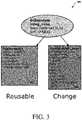
- FIG. 3illustrates a structure diagram of a subsystem integration repository 300 , according to an embodiment.
- SoC 100 of FIG. 1(and/or a Sandbox (SBX) logic) may refer to the subsystem integration repository 300 .
- SBXSandbox
- the subsystem descriptionmay be split into two parts: intra-subsystem 302 (which includes components that may be “reusable” from one design to another) and inter-subsystem 304 (which includes components that would likely “change” from one design to another).
- the intra-subsystem contentabstracts the details of the subsystem that are subsystem-specific and that will not need to change from product to product.
- the inter-subsystem contentcontains the aspect of the subsystem that interact with other subsystems and that might be customized for a specific product.
- the power domain that the IPs in the subsystem are associated withcan be changed through the inter-subsystem content.
- the attach points for the various fabricscan be customized by changing the inter-subsystem content.
- the intra-subsystem componentsmay include components that are reusable amongst different products such as instances, intra Subsystem (SS) connectivity logic, validation collateral logic, etc.
- the inter-subsystem componentsmay include components that are changed for different products such as connectivity logic to chassis, low power design collateral (e.g., in accordance with Unified Power Format (UPF)), clock logic, security logic, RTL logic, test island connectivity, suite of subsystem tests, etc.
- UPFUnified Power Format
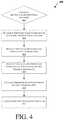
- FIG. 4illustrates a flow diagram of a method 400 to integrate one or more subsystems into an SoC, according to one or more embodiments.
- various logic/components/interfaces discussed with reference to FIGS. 1-3(such the processor 102 and/or graphics logic 103 of FIG. 1 and/or IPs discussed with reference to FIGS. 1-3 ) perform one or more operations of method 400 .
- a subsystemabstracts (e.g., all) logic components that are required for an architectural function.
- the determination of whether to generate the abstraction at operation 402may be made based on a user/external request and/or an indication that a subsystem would have a sufficient number of reusable components across a plurality of products/designs (see, e.g., the discussion of FIG. 3 ).
- an “architectural function” or “architectural feature”generally refers to a portion of an SoC capable of performing one or more operations to provide a distinct function, such as a USB (Universal Serial Bus), a PCIe (Peripheral Component Interconnect express) interface, a Controller Area Network (CAN) Bus, a security function, a manageability function, a display function, a graphics function, an imaging function, an artificial intelligence function, a Non-Volatile Memory express (NVMe) storage function, a Serial Advanced Technology Attachment (SATA) storage function, a video function, or an audio function.
- USBUniversal Serial Bus
- PCIePeripheral Component Interconnect express
- CANController Area Network
- a security functiona manageability function
- a display functionsuch as a graphics function, an imaging function, an artificial intelligence function, a Non-Volatile Memory express (NVMe) storage function, a Serial Advanced Technology Attachment (SATA) storage function, a video function, or an audio function
- all components of the subsystem that are used to support the architectural functionare determined.
- one or more interfaces between the logic components of the subsystemare provided (see, e.g., the discussion of FIG. 2 ).
- one or more interfaces between the logic components of the subsystem and one or more SoC chassis componentsare provided (see, e.g., the discussion of various interfaces/fabrics discussed with reference to FIGS. 1 and/or 2 ).
- components of the subsystemare packaged to provide an integrated SoC.
- the packaging of a subsystemcreates a reusable collateral that enables fast integration for all aspects of design.
- this packaging methodologycan cover aspects of design beyond RTL (Register Transfer Level) integration, including but not limited to validation of content for (e.g., all) design tools, UPF content, register validation content, and any required fuse settings.
- SOC package 502is coupled to a memory 560 via the memory controller 542 .
- the memory 560(or a portion of it) can be integrated on the SOC package 502 .
- the I/O interface 540may be coupled to one or more I/O devices 570 , e.g., via an interconnect and/or bus such as discussed herein with reference to other figures.
- I/O device(s) 570may include one or more of a keyboard, a mouse, a touchpad, a display, an image/video capture device (such as a camera or camcorder/video recorder), a touch screen, a speaker, or the like.
- FIG. 6is a block diagram of a processing system 600 , according to an embodiment.
- the system 600includes one or more processors 602 and one or more graphics processors 608 , and may be a single processor desktop system, a multiprocessor workstation system, or a server system having a large number of processors 602 or processor cores 607 .
- the system 600is a processing platform incorporated within a system-on-a-chip (SoC or SOC) integrated circuit for use in mobile, handheld, or embedded devices.
- SoCsystem-on-a-chip
- An embodiment of system 600can include, or be incorporated within a server-based gaming platform, a game console, including a game and media console, a mobile gaming console, a handheld game console, or an online game console.
- system 600is a mobile phone, smart phone, tablet computing device or mobile Internet device.
- Data processing system 600can also include, couple with, or be integrated within a wearable device, such as a smart watch wearable device, smart eyewear device, augmented reality device, or virtual reality device.
- data processing system 600is a television or set top box device having one or more processors 602 and a graphical interface generated by one or more graphics processors 608 .
- the one or more processors 602each include one or more processor cores 607 to process instructions which, when executed, perform operations for system and user software.
- each of the one or more processor cores 607is configured to process a specific instruction set 609 .
- instruction set 609may facilitate Complex Instruction Set Computing (CISC), Reduced Instruction Set Computing (RISC), or computing via a Very Long Instruction Word (VLIW).
- Multiple processor cores 607may each process a different instruction set 609 , which may include instructions to facilitate the emulation of other instruction sets.
- Processor core 607may also include other processing devices, such a Digital Signal Processor (DSP).
- DSPDigital Signal Processor
- the processor 602includes cache memory 604 .
- the processor 602can have a single internal cache or multiple levels of internal cache.
- the cache memoryis shared among various components of the processor 602 .
- the processor 602also uses an external cache (e.g., a Level-3 (L3) cache or Last Level Cache (LLC)) (not shown), which may be shared among processor cores 607 using known cache coherency techniques.
- L3 cacheLevel-3
- LLCLast Level Cache
- a register file 606is additionally included in processor 602 which may include different types of registers for storing different types of data (e.g., integer registers, floating point registers, status registers, and an instruction pointer register). Some registers may be general-purpose registers, while other registers may be specific to the design of the processor 602 .
- processor 602is coupled to a processor bus 610 to transmit communication signals such as address, data, or control signals between processor 602 and other components in system 600 .
- the system 600uses an exemplary ‘hub’ system architecture, including a memory controller hub 616 and an Input Output (I/O) controller hub 630 .
- a memory controller hub 616facilitates communication between a memory device and other components of system 600
- an I/O Controller Hub (ICH) 630provides connections to I/O devices via a local I/O bus.
- the logic of the memory controller hub 616is integrated within the processor.
- a high-performance network controller(not shown) couples to processor bus 610 .
- the system 600 shownis exemplary and not limiting, as other types of data processing systems that are differently configured may also be used.
- the I/O controller hub 630may be integrated within the one or more processor 602 , or the memory controller hub 616 and I/O controller hub 630 may be integrated into a discreet external graphics processor, such as the external graphics processor 612 .
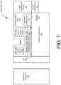
- FIG. 7is a block diagram of an embodiment of a processor 700 having one or more processor cores 702 A to 702 N, an integrated memory controller 714 , and an integrated graphics processor 708 .
- processor 700can include additional cores up to and including additional core 702 N represented by the dashed lined boxes.
- processor cores 702 A to 702 Nincludes one or more internal cache units 704 A to 704 N.
- each processor corealso has access to one or more shared cached units 706 .
- processor 700may also include a set of one or more bus controller units 716 and a system agent core 710 .
- the one or more bus controller units 716manage a set of peripheral buses, such as one or more Peripheral Component Interconnect buses (e.g., PCI, PCI Express).
- System agent core 710provides management functionality for the various processor components.
- system agent core 710includes one or more integrated memory controllers 714 to manage access to various external memory devices (not shown).
- one or more of the processor cores 702 A to 702 Ninclude support for simultaneous multi-threading.
- the system agent core 710includes components for coordinating and operating cores 702 A to 702 N during multi-threaded processing.
- System agent core 710may additionally include a power control unit (PCU), which includes logic and components to regulate the power state of processor cores 702 A to 702 N and graphics processor 708 .
- PCUpower control unit
- processor 700additionally includes graphics processor 708 to execute graphics processing operations.
- the graphics processor 708couples with the set of shared cache units 706 , and the system agent core 710 , including the one or more integrated memory controllers 714 .
- a display controller 711is coupled with the graphics processor 708 to drive graphics processor output to one or more coupled displays.
- display controller 711may be a separate module coupled with the graphics processor via at least one interconnect, or may be integrated within the graphics processor 708 or system agent core 710 .
- a ring-based interconnect unit 712is used to couple the internal components of the processor 700 .
- an alternative interconnect unitmay be used, such as a point-to-point interconnect, a switched interconnect, or other techniques, including techniques well known in the art.
- graphics processor 708couples with the ring interconnect 712 via an I/O link 713 .
- the exemplary I/O link 713represents at least one of multiple varieties of I/O interconnects, including an on package I/O interconnect which facilitates communication between various processor components and a high-performance embedded memory module 718 , such as an eDRAM (or embedded DRAM) module.
- a high-performance embedded memory module 718such as an eDRAM (or embedded DRAM) module.
- each of the processor cores 702 to 702 N and graphics processor 708use embedded memory modules 718 as a shared Last Level Cache.
- processor cores 702 A to 702 Nare homogenous cores executing the same instruction set architecture.
- processor cores 702 A to 702 Nare heterogeneous in terms of instruction set architecture (ISA), where one or more of processor cores 702 A to 702 N execute a first instruction set, while at least one of the other cores executes a subset of the first instruction set or a different instruction set.
- processor cores 702 A to 702 Nare heterogeneous in terms of microarchitecture, where one or more cores having a relatively higher power consumption couple with one or more power cores having a lower power consumption.
- processor 700can be implemented on one or more chips or as an SoC integrated circuit having the illustrated components, in addition to other components.
- Example 2includes the apparatus of example 1, wherein the first interface or the second interface comprise at least one of: a coherent fabric, a mesh network, an Open Core Protocol (OCP) interface, an Advanced Extensible Interface (AXI), an On-die System Fabric (OSF), a non-coherent fabric, a Universal Serial Bus (USB), a Peripheral Component Interconnect express (PCIe) interface, an Internetwork Packet Exchange (IPx) interface, a Serial Advanced Technology Attachment (SATA) interface, or a Controller Area Network (CAN) Bus.
- OCPOpen Core Protocol
- AXIAdvanced Extensible Interface
- OSFOn-die System Fabric
- USBUniversal Serial Bus
- PCIePeripheral Component Interconnect express
- IPxInternetwork Packet Exchange
- SATASerial Advanced Technology Attachment
- CANController Area Network
- Example 3includes the apparatus of example 1, wherein the chassis comprises one or more of: a power unit, a coherent fabric, an On-die System Fabric (OSF), a non-coherent fabric, and one or more Intellectual Property (IP) logic blocks.
- Example 4includes the apparatus of example 3, wherein the non-coherent fabric is to communicatively couple two or more components of the chassis and/or the subsystem, wherein the two or more components do not include a cache or memory that is to be kept coherent.
- Example 5includes the apparatus of example 3, wherein the coherent fabric is to communicatively couple two or more components of the chassis and/or the subsystem, wherein the two or more components include a cache or memory that is to be kept coherent.
- Example 8includes the apparatus of example 1, wherein the integration of the subsystem into the chassis of the SoC device allows for validation of a relationship between the architectural feature and another chassis feature or another architectural feature prior to manufacture.
- Example 9includes the apparatus of example 1, comprising logic circuitry to package components of the subsystem.
- Example 10includes the apparatus of example 1, comprising logic circuitry to package components of the subsystem, wherein packaging of the components of the subsystem is to generate a reusable collateral that allows for fast integration of all aspects of design in any SoC device with a compatible chassis prior to manufacture.
- Example 11includes the apparatus of example 1, comprising logic circuitry to validate the SoC device integrated with the subsystem.
- Example 12includes the apparatus of example 1, wherein the subsystem is to abstract the plurality of components.
- Example 13includes the apparatus of example 1, wherein the architectural feature comprises a portion of the SoC device that is capable of performing one or more operations to provide a distinct function.
- Example 14includes the apparatus of example 1, wherein a general-purpose processor or a graphics processor comprises the logic circuitry.
- Example 15includes the apparatus of example 14, wherein the general-purpose processor or the graphics processor each comprise one or more processor cores.
- Example 16includes the apparatus of example 1, wherein the SoC device comprises one or more of: the logic circuitry, a processor, a graphics processor, and memory.
- Example 17includes the apparatus of example 1, wherein an Internet of Things (IoT) device or a vehicle comprises one or more of: the logic circuitry, the SoC, the subsystem, one or more processors, and memory.
- IoTInternet of Things
- Example 18includes the apparatus of example 17, wherein the vehicle is one of: an automobile, a truck, a motorcycle, an airplane, a helicopter, a vessel/ship, a train, or a drone.
- Example 19includes the apparatus of example 1, wherein the subsystem comprises an intra-subsystem and an inter-subsystem, wherein the intra-subsystem comprises at least one component that is reusable from one design to another design, wherein the inter-subsystem comprises at least one component that changes across different designs.
- Example 20includes one or more computer-readable media comprising one or more instructions that when executed on at least one processor configure the at least one processor to perform one or more operations to: determine one or more components of a subsystem, wherein the subsystem is to support an architectural feature to be implemented on a System on Chip (SoC) device; determine a first interface to communicatively couple a first component of the subsystem to a second component of the subsystem or communicatively couple the first component of the subsystem to a first component of another subsystem; and determine a second interface to communicatively couple at least one component of the subsystem to at least one chassis component of the SoC device or to communicatively couple the at least one component of the subsystem to at least one non-chassis component of the other subsystem, wherein the subsystem is to be integrated into a chassis of the SoC device to allow for validation of the architectural feature.
- SoCSystem on Chip
- Example 21includes the one or more computer-readable media of example 20, further comprising one or more instructions that when executed on the at least one processor configure the at least one processor to perform one or more operations to cause the integration of the subsystem into the chassis of the SoC device to allow for validation of a relationship between the architectural feature and another chassis feature or another architectural feature.
- Example 22includes the one or more computer-readable media of example 20, further comprising one or more instructions that when executed on the at least one processor configure the at least one processor to perform one or more operations to cause the integration of the subsystem into the chassis of the SoC device to allow for validation of a relationship between the architectural feature and another chassis feature or another architectural feature prior to manufacture.
- Example 23includes a method comprising: determining one or more components of a subsystem, wherein the subsystem is to support an architectural feature to be implemented on a System on Chip (SoC) device; determining a first interface to communicatively couple a first component of the subsystem to a second component of the subsystem or communicatively couple the first component of the subsystem to a first component of another subsystem; and determining a second interface to communicatively couple at least one component of the subsystem to at least one chassis component of the SoC device or to communicatively couple the at least one component of the subsystem to at least one non-chassis component of the other subsystem, wherein the subsystem is to be integrated into a chassis of the SoC device to allow for validation of the architectural feature.
- SoCSystem on Chip
- Example 24includes the method of example 23, wherein the integration of the subsystem into the chassis of the SoC device allows for validation of a relationship between the architectural feature and another chassis feature or another architectural feature.
- Example 25includes the method of example 23, the integration of the subsystem into the chassis of the SoC device allows for validation of a relationship between the architectural feature and another chassis feature or another architectural feature prior to manufacture.
- Example 26includes an apparatus comprising means to perform a method as set forth in any preceding example.
- Example 27includes machine-readable storage including machine-readable instructions, when executed, to implement a method or realize an apparatus as set forth in any preceding example.
- the operations discussed hereinmay be implemented as hardware (e.g., logic circuitry or more generally circuitry or circuit), software, firmware, or combinations thereof, which may be provided as a computer program product, e.g., including a tangible (e.g., non-transitory) machine-readable or computer-readable medium having stored thereon instructions (or software procedures) used to program a computer to perform a process discussed herein.
- the machine-readable mediummay include a storage device such as those discussed with respect to FIG. 1 et seq.
- Such computer-readable mediamay be downloaded as a computer program product, wherein the program may be transferred from a remote computer (e.g., a server) to a requesting computer (e.g., a client) by way of data signals provided in a carrier wave or other propagation medium via a communication link (e.g., a bus, a modem, or a network connection).
- a remote computere.g., a server
- a requesting computere.g., a client
- a communication linke.g., a bus, a modem, or a network connection
- Coupledmay mean that two or more elements are in direct physical or electrical contact. However, “coupled” may also mean that two or more elements may not be in direct contact with each other, but may still cooperate or interact with each other.
Landscapes
- Engineering & Computer Science (AREA)
- Computer Hardware Design (AREA)
- Physics & Mathematics (AREA)
- Theoretical Computer Science (AREA)
- Evolutionary Computation (AREA)
- Geometry (AREA)
- General Engineering & Computer Science (AREA)
- General Physics & Mathematics (AREA)
- Design And Manufacture Of Integrated Circuits (AREA)
Abstract
Description
Claims (25)
Priority Applications (2)
| Application Number | Priority Date | Filing Date | Title |
|---|---|---|---|
| US16/509,482US10860762B2 (en) | 2019-07-11 | 2019-07-11 | Subsystem-based SoC integration |
| EP20162621.5AEP3764270A1 (en) | 2019-07-11 | 2020-03-12 | Subsystem-based soc integration |
Applications Claiming Priority (1)
| Application Number | Priority Date | Filing Date | Title |
|---|---|---|---|
| US16/509,482US10860762B2 (en) | 2019-07-11 | 2019-07-11 | Subsystem-based SoC integration |
Publications (2)
| Publication Number | Publication Date |
|---|---|
| US20190340313A1 US20190340313A1 (en) | 2019-11-07 |
| US10860762B2true US10860762B2 (en) | 2020-12-08 |
Family
ID=68384947
Family Applications (1)
| Application Number | Title | Priority Date | Filing Date |
|---|---|---|---|
| US16/509,482ActiveUS10860762B2 (en) | 2019-07-11 | 2019-07-11 | Subsystem-based SoC integration |
Country Status (2)
| Country | Link |
|---|---|
| US (1) | US10860762B2 (en) |
| EP (1) | EP3764270A1 (en) |
Families Citing this family (3)
| Publication number | Priority date | Publication date | Assignee | Title |
|---|---|---|---|---|
| US11537539B2 (en)* | 2020-10-19 | 2022-12-27 | Softiron Limited | Acceleration of data between a network and local I/O in a NUMA system |
| US12007895B2 (en)* | 2021-08-23 | 2024-06-11 | Apple Inc. | Scalable system on a chip |
| US20250103526A1 (en)* | 2023-09-27 | 2025-03-27 | Nxp Usa, Inc. | HARDWARE INTEGRATED QUALITY OF SERVICE (HiQoS) |
Citations (91)
| Publication number | Priority date | Publication date | Assignee | Title |
|---|---|---|---|---|
| US5432785A (en) | 1992-10-21 | 1995-07-11 | Bell Communications Research, Inc. | Broadband private virtual network service and system |
| US5764741A (en) | 1995-07-21 | 1998-06-09 | Callmanage Ltd. | Least cost rooting system |
| US5991308A (en) | 1995-08-25 | 1999-11-23 | Terayon Communication Systems, Inc. | Lower overhead method for data transmission using ATM and SCDMA over hybrid fiber coax cable plant |
| US6003029A (en) | 1997-08-22 | 1999-12-14 | International Business Machines Corporation | Automatic subspace clustering of high dimensional data for data mining applications |
| US6249902B1 (en) | 1998-01-09 | 2001-06-19 | Silicon Perspective Corporation | Design hierarchy-based placement |
| US20020071392A1 (en) | 2000-10-25 | 2002-06-13 | Telecommunications Research Laboratories, An Alberta Corporation | Design of a meta-mesh of chain sub-networks |
| US20020073380A1 (en) | 1998-09-30 | 2002-06-13 | Cadence Design Systems, Inc. | Block based design methodology with programmable components |
| US6415282B1 (en) | 1998-04-22 | 2002-07-02 | Nec Usa, Inc. | Method and apparatus for query refinement |
| US20020095430A1 (en) | 1999-12-30 | 2002-07-18 | Decode Genetics Ehf | SQL query generator utilizing matrix structures |
| US20030063605A1 (en) | 2001-09-28 | 2003-04-03 | Nec Usa, Inc. | Flexible crossbar switching fabric |
| US20040216072A1 (en) | 2003-04-17 | 2004-10-28 | International Business Machines Corporation | Porosity aware buffered steiner tree construction |
| US20050147081A1 (en) | 2003-12-26 | 2005-07-07 | Swarup Acharya | Route determination method and apparatus for virtually-concatenated data traffic |
| US6925627B1 (en) | 2002-12-20 | 2005-08-02 | Conexant Systems, Inc. | Method and apparatus for power routing in an integrated circuit |
| US20060161875A1 (en) | 2005-01-06 | 2006-07-20 | Chae-Eun Rhee | Method of creating core-tile-switch mapping architecture in on-chip bus and computer-readable medium for recording the method |
| US20060268909A1 (en) | 2005-05-31 | 2006-11-30 | Stmicroelectronics, Inc. | Hyper-Ring-on-Chip (HyRoC) architecture |
| US20070016880A1 (en)* | 2005-07-14 | 2007-01-18 | Brinson Kenneth O | Apparatus and method for testing sub-systems of a system-on-a-chip using a configurable external system-on-a-chip |
| US20070088537A1 (en) | 2005-04-11 | 2007-04-19 | Stmicroelectronics S.R.L. | Architecture for dynamically reconfigurable system-on-chip arrangements, related methods and computer program product |
| US20070118320A1 (en) | 2005-11-04 | 2007-05-24 | Synopsys, Inc. | Simulating topography of a conductive material in a semiconductor wafer |
| US20070244676A1 (en) | 2006-03-03 | 2007-10-18 | Li Shang | Adaptive analysis methods |
| US20070256044A1 (en) | 2006-04-26 | 2007-11-01 | Gary Coryer | System and method to power route hierarchical designs that employ macro reuse |
| US20070267680A1 (en) | 2006-05-17 | 2007-11-22 | Kabushiki Kaisha Toshiba | Semiconductor integrated circuit device |
| US7318214B1 (en) | 2003-06-19 | 2008-01-08 | Invarium, Inc. | System and method for reducing patterning variability in integrated circuit manufacturing through mask layout corrections |
| US20080072182A1 (en) | 2006-09-19 | 2008-03-20 | The Regents Of The University Of California | Structured and parameterized model order reduction |
| US20080120129A1 (en) | 2006-05-13 | 2008-05-22 | Michael Seubert | Consistent set of interfaces derived from a business object model |
| US20090070726A1 (en) | 2005-06-09 | 2009-03-12 | Pyxis Technology, Inc. | Enhanced Routing Grid System and Method |
| US20090070728A1 (en)* | 2007-09-12 | 2009-03-12 | Solomon Research Llc | IP cores in reconfigurable three dimensional integrated circuits |
| US7590959B2 (en) | 2005-10-31 | 2009-09-15 | Seiko Epson Corporation | Layout system, layout program, and layout method for text or other layout elements along a grid |
| US20090268677A1 (en) | 2008-04-24 | 2009-10-29 | National Taiwan University | network resource allocation system and method of the same |
| US20090313592A1 (en) | 2006-10-10 | 2009-12-17 | Ecole Polytechnique Federale De Lausanne (Epfl) | Method to design network-on-chip (noc) - based communication systems |
| US20100017656A1 (en)* | 2008-07-16 | 2010-01-21 | Samsung Electronics Co., Ltd. | System on chip (SOC) device verification system using memory interface |
| US20100040162A1 (en) | 2007-04-10 | 2010-02-18 | Naoki Suehiro | Transmission method, transmission device, receiving method, and receiving device |
| US7725859B1 (en) | 2003-08-01 | 2010-05-25 | Cadence Design Systems, Inc. | Methods and mechanisms for inserting metal fill data |
| US7808968B1 (en) | 1998-07-06 | 2010-10-05 | At&T Intellectual Property Ii, L.P. | Method for determining non-broadcast multiple access (NBMA) connectivity for routers having multiple local NBMA interfaces |
| US20110022754A1 (en) | 2007-12-06 | 2011-01-27 | Technion Research & Development Foundation Ltd | Bus enhanced network on chip |
| US20110035523A1 (en) | 2009-08-07 | 2011-02-10 | Brett Stanley Feero | Communication infrastructure for a data processing apparatus and a method of operation of such a communication infrastructure |
| US20110060831A1 (en) | 2008-06-12 | 2011-03-10 | Tomoki Ishii | Network monitoring device, bus system monitoring device, method and program |
| US20110072407A1 (en) | 2009-09-18 | 2011-03-24 | International Business Machines Corporation | Automatic Positioning of Gate Array Circuits in an Integrated Circuit Design |
| US7917885B2 (en) | 2005-06-27 | 2011-03-29 | Tela Innovations, Inc. | Methods for creating primitive constructed standard cells |
| US20110145909A1 (en)* | 2009-12-16 | 2011-06-16 | Ramana Rachakonda | Interface Logic For A Multi-Core System-On-A-Chip (SoC) |
| US20110154282A1 (en) | 2009-12-17 | 2011-06-23 | Springsoft, Inc. | Systems and methods for designing and making integrated circuits with consideration of wiring demand ratio |
| US20110191774A1 (en) | 2010-02-01 | 2011-08-04 | Yar-Sun Hsu | Noc-centric system exploration platform and parallel application communication mechanism description format used by the same |
| US8050256B1 (en) | 2008-07-08 | 2011-11-01 | Tilera Corporation | Configuring routing in mesh networks |
| US20110276937A1 (en) | 2005-06-24 | 2011-11-10 | Pulsic Limited | Integrated Circuit Routing with Compaction |
| US8059551B2 (en) | 2005-02-15 | 2011-11-15 | Raytheon Bbn Technologies Corp. | Method for source-spoofed IP packet traceback |
| US8099757B2 (en) | 2007-10-15 | 2012-01-17 | Time Warner Cable Inc. | Methods and apparatus for revenue-optimized delivery of content in a network |
| US20120023473A1 (en) | 2010-07-21 | 2012-01-26 | Brown Jeffrey S | Granular channel width for power optimization |
| US20120022841A1 (en) | 2010-07-22 | 2012-01-26 | Polyhedron Software Ltd. | Method and apparatus for estimating the state of a system |
| US20120026917A1 (en) | 2009-01-09 | 2012-02-02 | Microsoft Corporation | Server-centric high performance network architecture for modular data centers |
| US8136071B2 (en) | 2007-09-12 | 2012-03-13 | Neal Solomon | Three dimensional integrated circuits and methods of fabrication |
| US20120099475A1 (en) | 2010-10-21 | 2012-04-26 | Renesas Electronics Corporation | NoC SYSTEM AND INPUT SWITCHING DEVICE |
| US20120110541A1 (en) | 2010-10-29 | 2012-05-03 | International Business Machines Corporation | Constraint optimization of sub-net level routing in asic design |
| US20120117363A1 (en)* | 2010-11-05 | 2012-05-10 | Mark Cummings | Integrated circuit design and operation |
| US20120155250A1 (en) | 2010-12-21 | 2012-06-21 | Verizon Patent And Licensing Inc. | Method and system of providing micro-facilities for network recovery |
| US8281297B2 (en) | 2003-02-05 | 2012-10-02 | Arizona Board Of Regents | Reconfigurable processing |
| US8312402B1 (en) | 2008-12-08 | 2012-11-13 | Cadence Design Systems, Inc. | Method and apparatus for broadband electromagnetic modeling of three-dimensional interconnects embedded in multilayered substrates |
| US20130028090A1 (en) | 2010-05-12 | 2013-01-31 | Panasonic Corporation | Router and chip circuit |
| US20130051397A1 (en) | 2011-08-26 | 2013-02-28 | Sonics, Inc. | Credit flow control scheme in a router with flexible link widths utilizing minimal storage |
| US8407167B1 (en) | 2009-06-19 | 2013-03-26 | Google Inc. | Method for optimizing memory controller configuration in multi-core processors using fitness metrics and channel loads |
| US20130080073A1 (en) | 2010-06-11 | 2013-03-28 | Waters Technologies Corporation | Techniques for mass spectrometry peak list computation using parallel processing |
| US20130103369A1 (en) | 2011-10-25 | 2013-04-25 | Massachusetts Institute Of Technology | Methods and apparatus for constructing and analyzing component-based models of engineering systems |
| US20130124934A1 (en)* | 2011-10-01 | 2013-05-16 | Keith A. Jones | Packetizing jtag across industry standard interfaces |
| US8448102B2 (en) | 2006-03-09 | 2013-05-21 | Tela Innovations, Inc. | Optimizing layout of irregular structures in regular layout context |
| US20130151215A1 (en) | 2011-12-12 | 2013-06-13 | Schlumberger Technology Corporation | Relaxed constraint delaunay method for discretizing fractured media |
| US20130159944A1 (en) | 2011-12-15 | 2013-06-20 | Taiga Uno | Flare map calculating method and recording medium |
| US20130174113A1 (en) | 2011-12-30 | 2013-07-04 | Arteris SAS | Floorplan estimation |
| US20130185038A1 (en) | 2010-09-27 | 2013-07-18 | Telefonaktiebolaget L M Ericsson (Publ) | Performance Calculation, Admission Control, and Supervisory Control for a Load Dependent Data Processing System |
| US8492886B2 (en) | 2010-02-16 | 2013-07-23 | Monolithic 3D Inc | 3D integrated circuit with logic |
| US20130207801A1 (en) | 2012-02-14 | 2013-08-15 | James Barnes | Approach for prioritizing network alerts |
| US20130219148A1 (en) | 2012-02-17 | 2013-08-22 | National Taiwan University | Network on chip processor with multiple cores and routing method thereof |
| US20130215733A1 (en) | 2012-02-22 | 2013-08-22 | Nan Jiang | Speculative reservation for routing networks |
| US8533647B1 (en)* | 2012-10-05 | 2013-09-10 | Atrenta, Inc. | Method for generating an integrated and unified view of IP-cores for hierarchical analysis of a system on chip (SoC) design |
| US8541819B1 (en) | 2010-12-09 | 2013-09-24 | Monolithic 3D Inc. | Semiconductor device and structure |
| US20130263068A1 (en) | 2012-03-27 | 2013-10-03 | International Business Machines Corporation | Relative ordering circuit synthesis |
| US8601423B1 (en) | 2012-10-23 | 2013-12-03 | Netspeed Systems | Asymmetric mesh NoC topologies |
| US20130326458A1 (en) | 2012-06-01 | 2013-12-05 | International Business Machines Corporation | Timing refinement re-routing |
| US8667439B1 (en) | 2013-02-27 | 2014-03-04 | Netspeed Systems | Automatically connecting SoCs IP cores to interconnect nodes to minimize global latency and reduce interconnect cost |
| US20140068132A1 (en) | 2012-08-30 | 2014-03-06 | Netspeed Systems | Automatic construction of deadlock free interconnects |
| US20140092740A1 (en) | 2012-09-29 | 2014-04-03 | Ren Wang | Adaptive packet deflection to achieve fair, low-cost, and/or energy-efficient quality of service in network on chip devices |
| US20140098683A1 (en)* | 2012-10-09 | 2014-04-10 | Netspeed Systems | Heterogeneous channel capacities in an interconnect |
| US8705368B1 (en) | 2010-12-03 | 2014-04-22 | Google Inc. | Probabilistic distance-based arbitration |
| US8717875B2 (en) | 2011-04-15 | 2014-05-06 | Alcatel Lucent | Condensed core-energy-efficient architecture for WAN IP backbones |
| US8917111B1 (en)* | 2013-03-07 | 2014-12-23 | Xilinx Inc. | Configuration of programmable integrated circuits |
| US20150331043A1 (en)* | 2014-05-15 | 2015-11-19 | Manoj R. Sastry | System-on-chip secure debug |
| US20150382231A1 (en) | 2014-06-25 | 2015-12-31 | General Electric Company | Dynamic adjustment of a wireless network media access control parameter |
| US20160070634A1 (en)* | 2014-09-05 | 2016-03-10 | Qualcomm Incorporated | System and method for system-on-a-chip subsystem trace extraction and analysis |
| US20160103723A1 (en)* | 2014-10-14 | 2016-04-14 | Spansion Llc | System-on-chip verification |
| US20160146888A1 (en)* | 2014-11-26 | 2016-05-26 | Texas Instruments Incorporated | On-chip field testing methods and apparatus |
| US9633158B1 (en)* | 2014-11-11 | 2017-04-25 | Altera Corporation | Selectable reconfiguration for dynamically reconfigurable IP cores |
| US20170171913A1 (en)* | 2010-11-05 | 2017-06-15 | Mark Cummings | Self organizing system to implement emerging topologies |
| US20170185804A1 (en)* | 2015-12-23 | 2017-06-29 | Intel Corporation | Secure routing of trusted software transactions in unsecure fabric |
| US20170315944A1 (en)* | 2016-04-28 | 2017-11-02 | Infineon Technologies Ag | Scalable multi-core system-on-chip architecture on multiple dice for high end microcontroller |
- 2019
- 2019-07-11USUS16/509,482patent/US10860762B2/enactiveActive
- 2020
- 2020-03-12EPEP20162621.5Apatent/EP3764270A1/ennot_activeCeased
Patent Citations (98)
| Publication number | Priority date | Publication date | Assignee | Title |
|---|---|---|---|---|
| US5432785A (en) | 1992-10-21 | 1995-07-11 | Bell Communications Research, Inc. | Broadband private virtual network service and system |
| US5764741A (en) | 1995-07-21 | 1998-06-09 | Callmanage Ltd. | Least cost rooting system |
| US5991308A (en) | 1995-08-25 | 1999-11-23 | Terayon Communication Systems, Inc. | Lower overhead method for data transmission using ATM and SCDMA over hybrid fiber coax cable plant |
| US6003029A (en) | 1997-08-22 | 1999-12-14 | International Business Machines Corporation | Automatic subspace clustering of high dimensional data for data mining applications |
| US6249902B1 (en) | 1998-01-09 | 2001-06-19 | Silicon Perspective Corporation | Design hierarchy-based placement |
| US6415282B1 (en) | 1998-04-22 | 2002-07-02 | Nec Usa, Inc. | Method and apparatus for query refinement |
| US7808968B1 (en) | 1998-07-06 | 2010-10-05 | At&T Intellectual Property Ii, L.P. | Method for determining non-broadcast multiple access (NBMA) connectivity for routers having multiple local NBMA interfaces |
| US20020073380A1 (en) | 1998-09-30 | 2002-06-13 | Cadence Design Systems, Inc. | Block based design methodology with programmable components |
| US20020095430A1 (en) | 1999-12-30 | 2002-07-18 | Decode Genetics Ehf | SQL query generator utilizing matrix structures |
| US20020071392A1 (en) | 2000-10-25 | 2002-06-13 | Telecommunications Research Laboratories, An Alberta Corporation | Design of a meta-mesh of chain sub-networks |
| US20030063605A1 (en) | 2001-09-28 | 2003-04-03 | Nec Usa, Inc. | Flexible crossbar switching fabric |
| US6925627B1 (en) | 2002-12-20 | 2005-08-02 | Conexant Systems, Inc. | Method and apparatus for power routing in an integrated circuit |
| US8281297B2 (en) | 2003-02-05 | 2012-10-02 | Arizona Board Of Regents | Reconfigurable processing |
| US20040216072A1 (en) | 2003-04-17 | 2004-10-28 | International Business Machines Corporation | Porosity aware buffered steiner tree construction |
| US7065730B2 (en) | 2003-04-17 | 2006-06-20 | International Business Machines Corporation | Porosity aware buffered steiner tree construction |
| US7318214B1 (en) | 2003-06-19 | 2008-01-08 | Invarium, Inc. | System and method for reducing patterning variability in integrated circuit manufacturing through mask layout corrections |
| US7725859B1 (en) | 2003-08-01 | 2010-05-25 | Cadence Design Systems, Inc. | Methods and mechanisms for inserting metal fill data |
| US20050147081A1 (en) | 2003-12-26 | 2005-07-07 | Swarup Acharya | Route determination method and apparatus for virtually-concatenated data traffic |
| US20060161875A1 (en) | 2005-01-06 | 2006-07-20 | Chae-Eun Rhee | Method of creating core-tile-switch mapping architecture in on-chip bus and computer-readable medium for recording the method |
| US8059551B2 (en) | 2005-02-15 | 2011-11-15 | Raytheon Bbn Technologies Corp. | Method for source-spoofed IP packet traceback |
| US20070088537A1 (en) | 2005-04-11 | 2007-04-19 | Stmicroelectronics S.R.L. | Architecture for dynamically reconfigurable system-on-chip arrangements, related methods and computer program product |
| US20060268909A1 (en) | 2005-05-31 | 2006-11-30 | Stmicroelectronics, Inc. | Hyper-Ring-on-Chip (HyRoC) architecture |
| US20090070726A1 (en) | 2005-06-09 | 2009-03-12 | Pyxis Technology, Inc. | Enhanced Routing Grid System and Method |
| US20110276937A1 (en) | 2005-06-24 | 2011-11-10 | Pulsic Limited | Integrated Circuit Routing with Compaction |
| US7917885B2 (en) | 2005-06-27 | 2011-03-29 | Tela Innovations, Inc. | Methods for creating primitive constructed standard cells |
| US20070016880A1 (en)* | 2005-07-14 | 2007-01-18 | Brinson Kenneth O | Apparatus and method for testing sub-systems of a system-on-a-chip using a configurable external system-on-a-chip |
| US7590959B2 (en) | 2005-10-31 | 2009-09-15 | Seiko Epson Corporation | Layout system, layout program, and layout method for text or other layout elements along a grid |
| US20070118320A1 (en) | 2005-11-04 | 2007-05-24 | Synopsys, Inc. | Simulating topography of a conductive material in a semiconductor wafer |
| US20070244676A1 (en) | 2006-03-03 | 2007-10-18 | Li Shang | Adaptive analysis methods |
| US8448102B2 (en) | 2006-03-09 | 2013-05-21 | Tela Innovations, Inc. | Optimizing layout of irregular structures in regular layout context |
| US20070256044A1 (en) | 2006-04-26 | 2007-11-01 | Gary Coryer | System and method to power route hierarchical designs that employ macro reuse |
| US20080120129A1 (en) | 2006-05-13 | 2008-05-22 | Michael Seubert | Consistent set of interfaces derived from a business object model |
| US20070267680A1 (en) | 2006-05-17 | 2007-11-22 | Kabushiki Kaisha Toshiba | Semiconductor integrated circuit device |
| US20080072182A1 (en) | 2006-09-19 | 2008-03-20 | The Regents Of The University Of California | Structured and parameterized model order reduction |
| US20090313592A1 (en) | 2006-10-10 | 2009-12-17 | Ecole Polytechnique Federale De Lausanne (Epfl) | Method to design network-on-chip (noc) - based communication systems |
| US20100040162A1 (en) | 2007-04-10 | 2010-02-18 | Naoki Suehiro | Transmission method, transmission device, receiving method, and receiving device |
| US8136071B2 (en) | 2007-09-12 | 2012-03-13 | Neal Solomon | Three dimensional integrated circuits and methods of fabrication |
| US20090070728A1 (en)* | 2007-09-12 | 2009-03-12 | Solomon Research Llc | IP cores in reconfigurable three dimensional integrated circuits |
| US8099757B2 (en) | 2007-10-15 | 2012-01-17 | Time Warner Cable Inc. | Methods and apparatus for revenue-optimized delivery of content in a network |
| US20110022754A1 (en) | 2007-12-06 | 2011-01-27 | Technion Research & Development Foundation Ltd | Bus enhanced network on chip |
| US20090268677A1 (en) | 2008-04-24 | 2009-10-29 | National Taiwan University | network resource allocation system and method of the same |
| US20110060831A1 (en) | 2008-06-12 | 2011-03-10 | Tomoki Ishii | Network monitoring device, bus system monitoring device, method and program |
| US8050256B1 (en) | 2008-07-08 | 2011-11-01 | Tilera Corporation | Configuring routing in mesh networks |
| US20100017656A1 (en)* | 2008-07-16 | 2010-01-21 | Samsung Electronics Co., Ltd. | System on chip (SOC) device verification system using memory interface |
| US8312402B1 (en) | 2008-12-08 | 2012-11-13 | Cadence Design Systems, Inc. | Method and apparatus for broadband electromagnetic modeling of three-dimensional interconnects embedded in multilayered substrates |
| US20120026917A1 (en) | 2009-01-09 | 2012-02-02 | Microsoft Corporation | Server-centric high performance network architecture for modular data centers |
| US8407167B1 (en) | 2009-06-19 | 2013-03-26 | Google Inc. | Method for optimizing memory controller configuration in multi-core processors using fitness metrics and channel loads |
| US20110035523A1 (en) | 2009-08-07 | 2011-02-10 | Brett Stanley Feero | Communication infrastructure for a data processing apparatus and a method of operation of such a communication infrastructure |
| US20110072407A1 (en) | 2009-09-18 | 2011-03-24 | International Business Machines Corporation | Automatic Positioning of Gate Array Circuits in an Integrated Circuit Design |
| US20110145909A1 (en)* | 2009-12-16 | 2011-06-16 | Ramana Rachakonda | Interface Logic For A Multi-Core System-On-A-Chip (SoC) |
| US20110154282A1 (en) | 2009-12-17 | 2011-06-23 | Springsoft, Inc. | Systems and methods for designing and making integrated circuits with consideration of wiring demand ratio |
| US20110191774A1 (en) | 2010-02-01 | 2011-08-04 | Yar-Sun Hsu | Noc-centric system exploration platform and parallel application communication mechanism description format used by the same |
| US8492886B2 (en) | 2010-02-16 | 2013-07-23 | Monolithic 3D Inc | 3D integrated circuit with logic |
| US20130028090A1 (en) | 2010-05-12 | 2013-01-31 | Panasonic Corporation | Router and chip circuit |
| US20130080073A1 (en) | 2010-06-11 | 2013-03-28 | Waters Technologies Corporation | Techniques for mass spectrometry peak list computation using parallel processing |
| US20120023473A1 (en) | 2010-07-21 | 2012-01-26 | Brown Jeffrey S | Granular channel width for power optimization |
| US20120022841A1 (en) | 2010-07-22 | 2012-01-26 | Polyhedron Software Ltd. | Method and apparatus for estimating the state of a system |
| US20130185038A1 (en) | 2010-09-27 | 2013-07-18 | Telefonaktiebolaget L M Ericsson (Publ) | Performance Calculation, Admission Control, and Supervisory Control for a Load Dependent Data Processing System |
| US20120099475A1 (en) | 2010-10-21 | 2012-04-26 | Renesas Electronics Corporation | NoC SYSTEM AND INPUT SWITCHING DEVICE |
| US8543964B2 (en) | 2010-10-29 | 2013-09-24 | International Business Machines Corporation | Constraint optimization of sub-net level routing in asic design |
| US20120110541A1 (en) | 2010-10-29 | 2012-05-03 | International Business Machines Corporation | Constraint optimization of sub-net level routing in asic design |
| US20170171913A1 (en)* | 2010-11-05 | 2017-06-15 | Mark Cummings | Self organizing system to implement emerging topologies |
| US20120117363A1 (en)* | 2010-11-05 | 2012-05-10 | Mark Cummings | Integrated circuit design and operation |
| US8705368B1 (en) | 2010-12-03 | 2014-04-22 | Google Inc. | Probabilistic distance-based arbitration |
| US8541819B1 (en) | 2010-12-09 | 2013-09-24 | Monolithic 3D Inc. | Semiconductor device and structure |
| US20120155250A1 (en) | 2010-12-21 | 2012-06-21 | Verizon Patent And Licensing Inc. | Method and system of providing micro-facilities for network recovery |
| US8717875B2 (en) | 2011-04-15 | 2014-05-06 | Alcatel Lucent | Condensed core-energy-efficient architecture for WAN IP backbones |
| US20130051397A1 (en) | 2011-08-26 | 2013-02-28 | Sonics, Inc. | Credit flow control scheme in a router with flexible link widths utilizing minimal storage |
| US20130124934A1 (en)* | 2011-10-01 | 2013-05-16 | Keith A. Jones | Packetizing jtag across industry standard interfaces |
| US20130103369A1 (en) | 2011-10-25 | 2013-04-25 | Massachusetts Institute Of Technology | Methods and apparatus for constructing and analyzing component-based models of engineering systems |
| US20130151215A1 (en) | 2011-12-12 | 2013-06-13 | Schlumberger Technology Corporation | Relaxed constraint delaunay method for discretizing fractured media |
| US20130159944A1 (en) | 2011-12-15 | 2013-06-20 | Taiga Uno | Flare map calculating method and recording medium |
| US20130174113A1 (en) | 2011-12-30 | 2013-07-04 | Arteris SAS | Floorplan estimation |
| US20130207801A1 (en) | 2012-02-14 | 2013-08-15 | James Barnes | Approach for prioritizing network alerts |
| US20130219148A1 (en) | 2012-02-17 | 2013-08-22 | National Taiwan University | Network on chip processor with multiple cores and routing method thereof |
| US20130215733A1 (en) | 2012-02-22 | 2013-08-22 | Nan Jiang | Speculative reservation for routing networks |
| US20130263068A1 (en) | 2012-03-27 | 2013-10-03 | International Business Machines Corporation | Relative ordering circuit synthesis |
| US20130326458A1 (en) | 2012-06-01 | 2013-12-05 | International Business Machines Corporation | Timing refinement re-routing |
| US8635577B2 (en) | 2012-06-01 | 2014-01-21 | International Business Machines Corporation | Timing refinement re-routing |
| US20140068132A1 (en) | 2012-08-30 | 2014-03-06 | Netspeed Systems | Automatic construction of deadlock free interconnects |
| CN103684961A (en) | 2012-08-30 | 2014-03-26 | 网速系统公司 | Automatic construction of deadlock free interconnects |
| US20140092740A1 (en) | 2012-09-29 | 2014-04-03 | Ren Wang | Adaptive packet deflection to achieve fair, low-cost, and/or energy-efficient quality of service in network on chip devices |
| US8533647B1 (en)* | 2012-10-05 | 2013-09-10 | Atrenta, Inc. | Method for generating an integrated and unified view of IP-cores for hierarchical analysis of a system on chip (SoC) design |
| WO2014059024A1 (en) | 2012-10-09 | 2014-04-17 | Netspeed Systems | Heterogeneous channel capacities in an interconnect |
| US20140098683A1 (en)* | 2012-10-09 | 2014-04-10 | Netspeed Systems | Heterogeneous channel capacities in an interconnect |
| US20140115298A1 (en) | 2012-10-23 | 2014-04-24 | Netspeed Systems | ASYMMETRIC MESH NoC TOPOLOGIES |
| US20140115218A1 (en) | 2012-10-23 | 2014-04-24 | Netspeed Systems | ASYMMETRIC MESH NoC TOPOLOGIES |
| US8601423B1 (en) | 2012-10-23 | 2013-12-03 | Netspeed Systems | Asymmetric mesh NoC topologies |
| US8667439B1 (en) | 2013-02-27 | 2014-03-04 | Netspeed Systems | Automatically connecting SoCs IP cores to interconnect nodes to minimize global latency and reduce interconnect cost |
| US8917111B1 (en)* | 2013-03-07 | 2014-12-23 | Xilinx Inc. | Configuration of programmable integrated circuits |
| US20150331043A1 (en)* | 2014-05-15 | 2015-11-19 | Manoj R. Sastry | System-on-chip secure debug |
| US20150382231A1 (en) | 2014-06-25 | 2015-12-31 | General Electric Company | Dynamic adjustment of a wireless network media access control parameter |
| US20160070634A1 (en)* | 2014-09-05 | 2016-03-10 | Qualcomm Incorporated | System and method for system-on-a-chip subsystem trace extraction and analysis |
| US20160103723A1 (en)* | 2014-10-14 | 2016-04-14 | Spansion Llc | System-on-chip verification |
| US9633158B1 (en)* | 2014-11-11 | 2017-04-25 | Altera Corporation | Selectable reconfiguration for dynamically reconfigurable IP cores |
| US20160146888A1 (en)* | 2014-11-26 | 2016-05-26 | Texas Instruments Incorporated | On-chip field testing methods and apparatus |
| US20170185804A1 (en)* | 2015-12-23 | 2017-06-29 | Intel Corporation | Secure routing of trusted software transactions in unsecure fabric |
| US20170315944A1 (en)* | 2016-04-28 | 2017-11-02 | Infineon Technologies Ag | Scalable multi-core system-on-chip architecture on multiple dice for high end microcontroller |
Non-Patent Citations (24)
| Title |
|---|
| Ababei, C. et al., Achieving Network on Chip Fault Tolerance by Adaptive Remapping, Parallel & Distributed Processing, 2009, IEEE International Symposium, 4 pgs. |
| Abts, D., et al., Age-Based Packet Arbitration in Large-Radix k-ary n-cubes, Supercomputing 2007 (SC07), Nov. 10-16, 2007, 11 pgs. |
| Anonymous, "System on a Chip-Wikipedia", May 17, 2018, retrieved on Feb. 25, 2019. |
| Anonymous, "System on a Chip—Wikipedia", May 17, 2018, retrieved on Feb. 25, 2019. |
| Beretta, I. et al., A Mapping Flow for Dynamically Reconfigurable Multi-Core System-on-Chip Design, IEEE Transactions on Computer-Aided Design of Integrated Circuits and Systems, Aug. 2011, 30(8), pp. 1211-1224. |
| Das, R., et al., Aergia: Exploiting Packet Latency Slack in On-Chip Networks, 37th International Symposium on Computer Architecture (ISCA '10), Jun. 19-23, 2010, 11 pgs. |
| Ebrahimi, E., et al., Fairness via Source Throttling: A Configurable and High-Performance Fairness Substrate for Multi-Core Memory Systems, ASPLOS '10, Mar. 13-17, 2010, 12 pgs. |
| EP Extended Search Report dated Sep. 22, 2020, to EP Patent Application No. 20162621. |
| Gindin, R. et al., NoC-Based FPGA: Architecture and Routing. Proceedings of the First International Symposium on Networks-on-Chip (NOCS″07). May 2007. pp. 253-262. |
| Grot, B., Kilo-NOC: A Heterogeneous Network-on-Chip Architecture for Scalability and Service Guarantees, ISCA 11, Jun. 4-8, 2011, 12 pgs. |
| Grot, B., Preemptive Virtual Clock: A Flexible, Efficient, and Cost-Effective QOS Scheme for Networks-on-Chip, Micro '09, Dec. 12-16, 2009, 12 pgs. |
| Grot, B., Topology-Aware Quality-of-Service Support in Highly Integrated Chip Multiprocessors, 6th Annual Workshop on the Interaction between Operating Systems and Computer Architecture, Jun. 2006, 11 pgs. |
| Gwangsun Kim, John Kim KAIST, "Memory-centric System Interconnected Design with Hybrid Memory Cubes", 2013 IEEE, pp. 145-155. |
| International Search Report and Written Opinion for PCT/US2013/064140, dated Jan. 22, 2014, 9 pgs. |
| International Search Report and Written Opinion for PCT/US2014/012003, dated Mar. 26, 2014, 9 pgs. |
| International Search Report and Written Opinion for PCT/US2014/012012, dated May 14, 2014, 10 pgs. |
| International Search Report and Written Opinion for PCT/US2014/023625, dated Jul. 10, 2014. 9 pgs. |
| Jiang, N. et al., Performance Implications of Age-Based Allocations in On-Chip Networks, CVA Memo 129, May 24, 2011, 21 pgs. |
| Lee, J_ W. et al., Globally-Synchronized Frames for Guaranteed Quality-of-Service in On-Chip Networks, 35th IEEE/ACM International Symposium on Computer Architecture (ISCA), Jun. 2008, 12 pgs. |
| Lee, M. M. et al., Approximating Age-Based Arbitration in On-Chip Networks, PACT '10, Sep. 11-15, 2010, 2 pgs. |
| Li, B. et al., CoQoS: Coordinating QoS-Aware Shared Resources in NoC-based Socs, J_ Parallel Distrib. Comput., 71 (5), May 2011, 14 pgs. |
| Wasson, Scott, "Inside Intel's Atom C2000-Series 'Avoton' Processors" The Tech Report, Sep. 4, 2013. |
| Wasson, Scott, "Inside Intel's Atom C2000-Series ‘Avoton’ Processors" The Tech Report, Sep. 4, 2013. |
| Yang, J. et al., Homogeneous NoC-based FPGA: The Foundation for Virtual FPGA. 1oth IEEE International Conference on Computer and Information Technology (CIT 2010). Jun. 2010. pp. 62-67. |
Also Published As
| Publication number | Publication date |
|---|---|
| US20190340313A1 (en) | 2019-11-07 |
| EP3764270A1 (en) | 2021-01-13 |
Similar Documents
| Publication | Publication Date | Title |
|---|---|---|
| US11488935B1 (en) | Scalable network-on-package for connecting chiplet-based designs | |
| CN106575249B (en) | Low power debug architecture for Systems On Chip (SOC) and systems | |
| US9747245B2 (en) | Method, apparatus and system for integrating devices in a root complex | |
| US10860762B2 (en) | Subsystem-based SoC integration | |
| US10946866B2 (en) | Core tightly coupled lockstep for high functional safety | |
| US8825922B2 (en) | Arrangement for processing trace data information, integrated circuits and a method for processing trace data information | |
| KR20160074645A (en) | Integrated component interconnect | |
| US20190052277A1 (en) | Functional safety clocking framework for real time systems | |
| US11561779B1 (en) | Applications for hardware accelerators in computing systems | |
| US9935637B2 (en) | Systems and methods for FPGA development and operation | |
| GB2609693A (en) | Multiple independant on-chip interconnect | |
| Amos et al. | FPGA-based prototyping methodology manual: Best practices in design-for-prototyping | |
| CN114972523A (en) | Determining optical centers in images | |
| EP2605105A2 (en) | Mobile electronic devices utilizing reconfigurable processing techniques to enable higher speed applications with lowered power consumption | |
| US20140181491A1 (en) | Field-programmable module for interface bridging and input/output expansion | |
| US11513848B2 (en) | Critical agent identification to modify bandwidth allocation in a virtual channel | |
| Goulding-Hotta | Specialization as a Candle in the Dark Silicon Regime | |
| US9507741B2 (en) | System-on-chip design structure | |
| US20250052809A1 (en) | Device, method and system for in-field lane testing and repair with a three-dimensional integrated circuit | |
| US11029964B1 (en) | Booting a system-on-chip | |
| US10747928B2 (en) | Diagnostic testing of FPGAs for safety critical systems | |
| US20240385946A1 (en) | Sensor-based control for debug invasiveness | |
| PL | Zynq-7000 All Programmable SoC Overview | |
| Maaref | Architecting and Building High-Speed SoCs | |
| US20250104742A1 (en) | Adjustable Clock and Power Gating Control |
Legal Events
| Date | Code | Title | Description |
|---|---|---|---|
| FEPP | Fee payment procedure | Free format text:ENTITY STATUS SET TO UNDISCOUNTED (ORIGINAL EVENT CODE: BIG.); ENTITY STATUS OF PATENT OWNER: LARGE ENTITY | |
| STPP | Information on status: patent application and granting procedure in general | Free format text:DOCKETED NEW CASE - READY FOR EXAMINATION | |
| AS | Assignment | Owner name:INTEL CORPORATION, CALIFORNIA Free format text:ASSIGNMENT OF ASSIGNORS INTEREST;ASSIGNORS:ADLER, ROBERT P.;SUNDER, RAMAMURTHY;BOLLINENI, HANUMANTH;AND OTHERS;SIGNING DATES FROM 20190712 TO 20191223;REEL/FRAME:051367/0784 | |
| STPP | Information on status: patent application and granting procedure in general | Free format text:NON FINAL ACTION MAILED | |
| STPP | Information on status: patent application and granting procedure in general | Free format text:RESPONSE TO NON-FINAL OFFICE ACTION ENTERED AND FORWARDED TO EXAMINER | |
| STPP | Information on status: patent application and granting procedure in general | Free format text:PUBLICATIONS -- ISSUE FEE PAYMENT VERIFIED | |
| STCF | Information on status: patent grant | Free format text:PATENTED CASE | |
| AS | Assignment | Owner name:TAHOE RESEARCH, LTD., IRELAND Free format text:ASSIGNMENT OF ASSIGNORS INTEREST;ASSIGNOR:INTEL CORPORATION;REEL/FRAME:061175/0176 Effective date:20220718 | |
| MAFP | Maintenance fee payment | Free format text:PAYMENT OF MAINTENANCE FEE, 4TH YEAR, LARGE ENTITY (ORIGINAL EVENT CODE: M1551); ENTITY STATUS OF PATENT OWNER: LARGE ENTITY Year of fee payment:4 |