US10860094B2 - Execution of function based on location of display at which a user is looking and manipulation of an input device - Google Patents
Execution of function based on location of display at which a user is looking and manipulation of an input deviceDownload PDFInfo
- Publication number
- US10860094B2 US10860094B2US14/643,505US201514643505AUS10860094B2US 10860094 B2US10860094 B2US 10860094B2US 201514643505 AUS201514643505 AUS 201514643505AUS 10860094 B2US10860094 B2US 10860094B2
- Authority
- US
- United States
- Prior art keywords
- input
- display
- processor
- location
- user
- Prior art date
- Legal status (The legal status is an assumption and is not a legal conclusion. Google has not performed a legal analysis and makes no representation as to the accuracy of the status listed.)
- Active, expires
Links
Images


Classifications
- G—PHYSICS
- G06—COMPUTING OR CALCULATING; COUNTING
- G06F—ELECTRIC DIGITAL DATA PROCESSING
- G06F3/00—Input arrangements for transferring data to be processed into a form capable of being handled by the computer; Output arrangements for transferring data from processing unit to output unit, e.g. interface arrangements
- G06F3/01—Input arrangements or combined input and output arrangements for interaction between user and computer
- G06F3/011—Arrangements for interaction with the human body, e.g. for user immersion in virtual reality
- G06F3/013—Eye tracking input arrangements
- G—PHYSICS
- G06—COMPUTING OR CALCULATING; COUNTING
- G06F—ELECTRIC DIGITAL DATA PROCESSING
- G06F3/00—Input arrangements for transferring data to be processed into a form capable of being handled by the computer; Output arrangements for transferring data from processing unit to output unit, e.g. interface arrangements
- G06F3/01—Input arrangements or combined input and output arrangements for interaction between user and computer
- G06F3/017—Gesture based interaction, e.g. based on a set of recognized hand gestures
- G—PHYSICS
- G06—COMPUTING OR CALCULATING; COUNTING
- G06F—ELECTRIC DIGITAL DATA PROCESSING
- G06F3/00—Input arrangements for transferring data to be processed into a form capable of being handled by the computer; Output arrangements for transferring data from processing unit to output unit, e.g. interface arrangements
- G06F3/01—Input arrangements or combined input and output arrangements for interaction between user and computer
- G06F3/03—Arrangements for converting the position or the displacement of a member into a coded form
- G06F3/033—Pointing devices displaced or positioned by the user, e.g. mice, trackballs, pens or joysticks; Accessories therefor
- G06F3/0346—Pointing devices displaced or positioned by the user, e.g. mice, trackballs, pens or joysticks; Accessories therefor with detection of the device orientation or free movement in a 3D space, e.g. 3D mice, 6-DOF [six degrees of freedom] pointers using gyroscopes, accelerometers or tilt-sensors
- G—PHYSICS
- G06—COMPUTING OR CALCULATING; COUNTING
- G06F—ELECTRIC DIGITAL DATA PROCESSING
- G06F3/00—Input arrangements for transferring data to be processed into a form capable of being handled by the computer; Output arrangements for transferring data from processing unit to output unit, e.g. interface arrangements
- G06F3/01—Input arrangements or combined input and output arrangements for interaction between user and computer
- G06F3/03—Arrangements for converting the position or the displacement of a member into a coded form
- G06F3/033—Pointing devices displaced or positioned by the user, e.g. mice, trackballs, pens or joysticks; Accessories therefor
- G06F3/0354—Pointing devices displaced or positioned by the user, e.g. mice, trackballs, pens or joysticks; Accessories therefor with detection of 2D relative movements between the device, or an operating part thereof, and a plane or surface, e.g. 2D mice, trackballs, pens or pucks
- G06F3/03545—Pens or stylus
- G—PHYSICS
- G06—COMPUTING OR CALCULATING; COUNTING
- G06F—ELECTRIC DIGITAL DATA PROCESSING
- G06F3/00—Input arrangements for transferring data to be processed into a form capable of being handled by the computer; Output arrangements for transferring data from processing unit to output unit, e.g. interface arrangements
- G06F3/01—Input arrangements or combined input and output arrangements for interaction between user and computer
- G06F3/048—Interaction techniques based on graphical user interfaces [GUI]
- G06F3/0484—Interaction techniques based on graphical user interfaces [GUI] for the control of specific functions or operations, e.g. selecting or manipulating an object, an image or a displayed text element, setting a parameter value or selecting a range
- G06F3/04842—Selection of displayed objects or displayed text elements
- G—PHYSICS
- G06—COMPUTING OR CALCULATING; COUNTING
- G06F—ELECTRIC DIGITAL DATA PROCESSING
- G06F3/00—Input arrangements for transferring data to be processed into a form capable of being handled by the computer; Output arrangements for transferring data from processing unit to output unit, e.g. interface arrangements
- G06F3/01—Input arrangements or combined input and output arrangements for interaction between user and computer
- G06F3/048—Interaction techniques based on graphical user interfaces [GUI]
- G06F3/0487—Interaction techniques based on graphical user interfaces [GUI] using specific features provided by the input device, e.g. functions controlled by the rotation of a mouse with dual sensing arrangements, or of the nature of the input device, e.g. tap gestures based on pressure sensed by a digitiser
- G06F3/0488—Interaction techniques based on graphical user interfaces [GUI] using specific features provided by the input device, e.g. functions controlled by the rotation of a mouse with dual sensing arrangements, or of the nature of the input device, e.g. tap gestures based on pressure sensed by a digitiser using a touch-screen or digitiser, e.g. input of commands through traced gestures
- G06F3/04883—Interaction techniques based on graphical user interfaces [GUI] using specific features provided by the input device, e.g. functions controlled by the rotation of a mouse with dual sensing arrangements, or of the nature of the input device, e.g. tap gestures based on pressure sensed by a digitiser using a touch-screen or digitiser, e.g. input of commands through traced gestures for inputting data by handwriting, e.g. gesture or text
Definitions
- the present applicationrelates generally to executing a function at a device based on a location of a display at which a user is looking and manipulation of an input device.
- an apparatusincludes a processor, a sensor accessible to the processor, a display accessible to the processor, and memory accessible to the processor.
- the memorybears instructions executable by the processor to receive first input from the sensor, and based on the first input, identify a location on the display at which a user is looking.
- the instructionsare also executable to receive second input from an input device in communication with the apparatus and, responsive to receipt of the second input and based on the location on the display, execute a function at the apparatus regardless of a location of the input device when the second input was received.
- a methodin another aspect, includes receiving first input from a camera, and based on the first input, identifying a location of a display at which a person is looking. The method also includes receiving second input from a input device, where the second input is input received other than based on physical contact of the input device with the display, and based at least in part on the location and responsive to receiving the second input, performing an operation at a device.
- an apparatusin yet another aspect, includes a first processor, a network adapter, and storage bearing instructions executable by a second processor for performing a task using the second processor responsive to identification of a user looking at an area of a display and receipt of input generated based on manipulation of an input device other than against the display.
- the first processortransfers the instructions over a network via the network adapter.
- FIG. 1is a block diagram of an example system in accordance with present principles
- FIG. 2is a block diagram of a network of devices in accordance with present principles
- FIG. 3is a flow chart showing an example algorithm in accordance with present principles
- FIGS. 4-12are example illustrations in accordance with present principles.
- FIG. 13is an example user interface (UI) in accordance with present principles.
- a systemmay include server and client components, connected over a network such that data may be exchanged between the client and server components.
- the client componentsmay include one or more computing devices including televisions (e.g. smart TVs, Internet-enabled TVs), computers such as desktops, laptops and tablet computers, so-called convertible devices (e.g. having a tablet configuration and laptop configuration), and other mobile devices including smart phones.
- These client devicesmay employ, as non-limiting examples, operating systems from Apple, Google, or Microsoft. A Unix or similar such as Linux operating system may be used.
- These operating systemscan execute one or more browsers such as a browser made by Microsoft or Google or Mozilla or other browser program that can access web applications hosted by the Internet servers over a network such as the Internet, a local intranet, or a virtual private network.
- instructionsrefer to computer-implemented steps for processing information in the system. Instructions can be implemented in software, firmware or hardware; hence, illustrative components, blocks, modules, circuits, and steps are set forth in terms of their functionality.
- a processormay be any conventional general purpose single- or multi-chip processor that can execute logic by means of various lines such as address lines, data lines, and control lines and registers and shift registers. Moreover, any logical blocks, modules, and circuits described herein can be implemented or performed, in addition to a general purpose processor, in or by a digital signal processor (DSP), a field programmable gate array (FPGA) or other programmable logic device such as an application specific integrated circuit (ASIC), discrete gate or transistor logic, discrete hardware components, or any combination thereof designed to perform the functions described herein.
- DSPdigital signal processor
- FPGAfield programmable gate array
- ASICapplication specific integrated circuit
- a processorcan be implemented by a controller or state machine or a combination of computing devices.
- Any software and/or applications described by way of flow charts and/or user interfaces hereincan include various sub-routines, procedures, etc. It is to be understood that logic divulged as being executed by e.g. a module can be redistributed to other software modules and/or combined together in a single module and/or made available in a shareable library.
- Logic when implemented in softwarecan be written in an appropriate language such as but not limited to C # or C++, and can be stored on or transmitted through a computer-readable storage medium (e.g. that may not be a transitory signal) such as a random access memory (RAM), read-only memory (ROM), electrically erasable programmable read-only memory (EEPROM), compact disk read-only memory (CD-ROM) or other optical disk storage such as digital versatile disc (DVD), magnetic disk storage or other magnetic storage devices including removable thumb drives, etc.
- a connectionmay establish a computer-readable medium.
- Such connectionscan include, as examples, hard-wired cables including fiber optics and coaxial wires and twisted pair wires.
- Such connectionsmay include wireless communication connections including infrared and radio.
- a processorcan access information over its input lines from data storage, such as the computer readable storage medium, and/or the processor can access information wirelessly from an Internet server by activating a wireless transceiver to send and receive data.
- Datatypically is converted from analog signals to digital by circuitry between the antenna and the registers of the processor when being received and from digital to analog when being transmitted.
- the processorthen processes the data through its shift registers to output calculated data on output lines, for presentation of the calculated data on the device.
- a system having at least one of A, B, and Cincludes systems that have A alone, B alone, C alone, A and B together, A and C together, B and C together, and/or A, B, and C together, etc.
- a system having one or more of A, B, and Cincludes systems that have A alone, B alone, C alone, A and B together, A and C together, B and C together, and/or A, B, and C together, etc.
- circuitryincludes all levels of available integration, e.g., from discrete logic circuits to the highest level of circuit integration such as VLSI, and includes programmable logic components programmed to perform the functions of an embodiment as well as general-purpose or special-purpose processors programmed with instructions to perform those functions.
- FIG. 1it shows an example block diagram of an information handling system and/or computer system 100 .
- the system 100may be a desktop computer system, such as one of the ThinkCentre® or ThinkPad®, series of personal computers sold by Lenovo (US) Inc. of Morrisville, N.C. or a workstation computer, such as the ThinkStation®, which are sold by Lenovo (US) Inc. of Morrisville, N.C.; however, as apparent from the description herein, a client device, a server or other machine in accordance with present principles may include other features or only some of the features of the system 100 .
- the system 100may be e.g. a game console such as XBOX® or Playstation®.
- the system 100includes a so-called chipset 110 .
- a chipsetrefers to a group of integrated circuits, or chips, that are designed to work together. Chipsets are usually marketed as a single product (e.g., consider chipsets marketed under the brands INTEL®, AMD®, etc.).
- the chipset 110has a particular architecture, which may vary to some extent depending on brand or manufacturer.
- the architecture of the chipset 110includes a core and memory control group 120 and an I/O controller hub 150 that exchange information (e.g., data, signals, commands, etc.) via, for example, a direct management interface or direct media interface (DMI) 142 or a link controller 144 .
- DMIdirect management interface or direct media interface
- the DMI 142is a chip-to-chip interface (sometimes referred to as being a link between a “northbridge” and a “southbridge”).
- the core and memory control group 120include one or more processors 122 (e.g., single core or multi-core, etc.) and a memory controller hub 126 that exchange information via a front side bus (FSB) 124 .
- processors 122e.g., single core or multi-core, etc.
- memory controller hub 126that exchange information via a front side bus (FSB) 124 .
- FSAfront side bus
- various components of the core and memory control group 120may be integrated onto a single processor die, for example, to make a chip that supplants the conventional “northbridge” style architecture.
- the memory controller hub 126interfaces with memory 140 .
- the memory controller hub 126may provide support for DDR SDRAM memory (e.g., DDR, DDR2, DDR3, etc.).
- DDR SDRAM memorye.g., DDR, DDR2, DDR3, etc.
- the memory 140is a type of random-access memory (RAM). It is often referred to as “system memory.”
- the memory controller hub 126further includes a low-voltage differential signaling interface (LVDS) 132 .
- the LVDS 132may be a so-called LVDS Display Interface (LDI) for support of a display device 192 (e.g., a CRT, a flat panel, a projector, a touch-enabled display, a display comprising a pen digitizer for receiving input from a pen and/or stylus, etc.).
- a block 138includes some examples of technologies that may be supported via the LVDS interface 132 (e.g., serial digital video, HDMI/DVI, display port).
- the memory controller hub 126also includes one or more PCI-express interfaces (PCI-E) 134 , for example, for support of discrete graphics 136 .
- PCI-EPCI-express interfaces
- Discrete graphics using a PCI-E interfacehas become an alternative approach to an accelerated graphics port (AGP).
- the memory controller hub 126may include a 16-lane ( ⁇ 16) PCI-E port for an external PCI-E-based graphics card (including e.g. one of more GPUs).
- An example systemmay include AGP or PCI-E for support of graphics.
- the I/O hub controller 150includes a variety of interfaces.
- the example of FIG. 1includes a SATA interface 151 , one or more PCI-E interfaces 152 (optionally one or more legacy PCI interfaces), one or more USB interfaces 153 , a LAN interface 154 (more generally a network interface for communication over at least one network such as the Internet, a WAN, a LAN, etc.
- the I/O hub controller 150may include integrated gigabit Ethernet controller lines multiplexed with a PCI-E interface port. Other network features may operate independent of a PCI-E interface.
- the interfaces of the I/O hub controller 150provide for communication with various devices, networks, etc.
- the SATA interface 151provides for reading, writing or reading and writing information on one or more drives 180 such as HDDs, SDDs or a combination thereof, but in any case the drives 180 are understood to be e.g. tangible computer readable storage mediums that may not be transitory signals.
- the I/O hub controller 150may also include an advanced host controller interface (AHCI) to support one or more drives 180 .
- AHCIadvanced host controller interface
- the PCI-E interface 152allows for wireless connections 182 to devices, networks, etc.
- the USB interface 153provides for input devices 184 such as keyboards (KB), mice and various other devices (e.g., cameras, phones, storage, media players, etc.).
- the LPC interface 170provides for use of one or more ASICs 171 , a trusted platform module (TPM) 172 , a super I/O 173 , a firmware hub 174 , BIOS support 175 as well as various types of memory 176 such as ROM 177 , Flash 178 , and non-volatile RAM (NVRAM) 179 .
- TPMtrusted platform module
- this modulemay be in the form of a chip that can be used to authenticate software and hardware devices.
- a TPMmay be capable of performing platform authentication and may be used to verify that a system seeking access is the expected system.
- the system 100upon power on, may be configured to execute boot code 190 for the BIOS 168 , as stored within the SPI Flash 166 , and thereafter processes data under the control of one or more operating systems and application software (e.g., stored in system memory 140 ).
- An operating systemmay be stored in any of a variety of locations and accessed, for example, according to instructions of the BIOS 168 .
- the system 100also includes at least one sensor 198 for tracking a user's eyes and/or eye focus in accordance with present principles, such as e.g. a camera for gathering one or more images and providing input related thereto to the processor 122 .
- the cameramay be, e.g., a thermal imaging camera, a digital camera such as a webcam, a three-dimensional (3D) camera, and/or a camera integrated into the system 100 and controllable by the processor 122 to gather pictures/images and/or video.
- the system 100may include a gyroscope for e.g. sensing and/or measuring the orientation of the system 100 and providing input related thereto to the processor 122 , an accelerometer for e.g. sensing acceleration and/or movement of the system 100 and providing input related thereto to the processor 122 , and an audio receiver/microphone providing input to the processor 122 e.g. based on a user providing audible input to the microphone.
- the system 100may include a GPS transceiver that is configured to e.g. receive geographic position information from at least one satellite and provide the information to the processor 122 .
- another suitable position receiverother than a GPS receiver may be used in accordance with present principles to e.g. determine the location of the system 100 .
- an example client device or other machine/computermay include fewer or more features than shown on the system 100 of FIG. 1 .
- the system 100is configured to undertake present principles.
- FIG. 2it shows example devices communicating over a network 200 such as e.g. the Internet in accordance with present principles. It is to be understood that e.g. each of the devices described in reference to FIG. 2 may include at least some of the features, components, and/or elements of the system 100 described above.
- FIG. 2shows a notebook computer 202 , a desktop computer 204 , a wearable device 206 (such as e.g.
- a smart watcha smart band and/or smart ring disposable around a person's arm or finger, a smart device engageable with at least a portion of a person's ear, etc.
- a smart television (TV) 208e.g. a stylus 216 (comprising e.g. a button 218 generating input to the a processor of the stylus 216 , a motion sensor 220 such as an accelerometer or gyroscope, and a contact sensor 222 such as e.g. a pen tip configured for sensing contact of the pen tip against an object), an input pad 224 configured for detecting contact of an object with the pad, and a mouse 226 .
- a stylus 216comprising e.g. a button 218 generating input to the a processor of the stylus 216
- a motion sensor 220such as an accelerometer or gyroscope
- a contact sensor 222such as e.g. a pen tip configured for sensing contact
- FIG. 2also shows a server 214 such as e.g. an Internet server that may e.g. provide cloud storage accessible to the devices 202 - 212 , 216 , 224 , and 226 . It is to be understood that the devices 202 - 216 , 224 , and 226 are configured to communicate with each other over the network 200 to undertake present principles.
- a server 214such as e.g. an Internet server that may e.g. provide cloud storage accessible to the devices 202 - 212 , 216 , 224 , and 226 . It is to be understood that the devices 202 - 216 , 224 , and 226 are configured to communicate with each other over the network 200 to undertake present principles.
- FIG. 3it shows example logic that may be undertaken by a device such as the system 100 in accordance with present principles (referred to below as the “present device”).
- the logicinitiates and/or executes one or more applications for undertaking present principles, such as e.g. an eye tracking application, a camera application, an input receiving application (e.g. for communicating with a wireless input device such as a stylus), a gesture recognition application, and/or a single application integrating one or more of the foregoing.
- the logicproceeds to block 302 , where the logic receives first input from a camera (e.g. a series of images from the camera and/or a real-time video feed).
- a camerae.g. a series of images from the camera and/or a real-time video feed.
- the logicthen moves to block 304 , where the logic identifies at least one location on a display in communication with the present device at which a person identified from the first input is looking.
- the logicmay identify the location applying eye tracking software and/or principles to the first input received from the camera.
- the logic of FIG. 3moves to block 306 , where the logic receives second input from an input device such as e.g. a stylus, a mouse, an electronic ring wearable around a person's finger or arm, an electronic pad, etc. Responsive to the second input that is received at block 306 , the logic moves to block 308 .
- an input devicesuch as e.g. a stylus, a mouse, an electronic ring wearable around a person's finger or arm, an electronic pad, etc. Responsive to the second input that is received at block 306 , the logic moves to block 308 .
- the logicidentifies data associated with the second input (e.g. based on the second input itself, and/or based on metadata that was transmitted from the input device with the second input), such as e.g. identification of a device type from which the second input was received (e.g. a stylus input device type, a mouse input device type), identification of a component type from which the second input of the input device was generated (e.g. a contact sensor on the input device, a motion sensor on the input device, a particular button on the input device, etc.), and/or identification of a specific command associated with the second input, the input device itself, and/or the component of the input device which generated the second input.
- the logicmay do so at block 308 by e.g.
- a data table stored at the present devicewhich correlates various inputs, input device types, and/or component types with particular commands, locating an entry in the data table corresponding to the second input received at block 306 , and then accessing associated data for the entry also stored in the data table.
- the logicmoves to block 310 .
- the logicbased on the identified location and second input (and/or second input data identified at block 308 ), executes a function, task, and/or operation.
- a function, task, and/or operationinclude, but are not limited to, replacement of a character (e.g. alphabetical or numerical character) or word presented on the display at the identified location, removal of a character or word presented on the display at the identified location, insertion of a character or word at the identified location, selection of an element presented on the display at the identified location, presentation of a menu associated with an element presented on the display at the identified location, highlighting of an element presented on the display at the identified location, etc.
- the logicmay execute a function, task, and/or operation at block 308 based on the location and second input e.g. regardless of a position of a cursor presented on the display and/or regardless of the location of the input device (e.g. regardless of whether the input device was used to direct input directly to the display itself or based on contact with another object).
- the logicmay, if no display location is identifiable based on the first input (e.g. if the first input does not comprise an image of a user's face from which an area of the display being looked at may be identified), either end or undertake a function based on the second input using e.g. a current location of a cursor presented on the display.
- FIG. 4it shows an example illustration 400 of present principles.
- a display 402 at the left portion of FIG. 4is shown as presenting information thereon, including text 404 comprising “My game is Russell.”
- the device controlling the display 402has identified area 406 comprising the word “game” as an area of the display 402 being looked at by a user, the area 406 understood to not comprise the entire area of the display 402 on which images are presentable.
- the box shown on the display 402 corresponding to the area 406may not actually be presented thereon and is shown in FIG. 4 for illustration, though it is to also be understood that in some embodiments, such a box may actually be presented on the display 402 .
- the middle portion of FIG. 4shows that a user's finger 408 presses a button 410 on one end of a stylus 412 .
- the right portion of FIG. 4shows that the device controlling the display 402 has caused the display 402 to replace the word “game” previously presented at area 406 with the word “name” based on e.g. the determining based on the context of the text 404 that “name” was likely what the user intended to be presented at area 406 even though “game” was previously presented.
- buttons 410again be pressed, the device may cause to be presented at area 406 yet another possibility other than “name” or “game.”
- selection of the button 410is recognized by the device as a command to rotate or replace one item presented on the display with another.
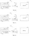
- FIG. 5it also shows an example illustration 500 of present principles.
- a display 502 at the left portion of FIG. 5is shown as presenting selector elements thereon (e.g. tiles, icons, files, etc.), including selector element one, selector element two, selector element three, and selector element four.
- the device controlling the display 502has identified area 506 comprising selector element one as an area of the display 502 being looked at by a user, the area 506 understood to not comprise the entire area of the display 502 on which images are presentable.
- the box corresponding to the area 506 shown on the display 502may not actually be presented thereon and is shown in FIG. 5 for illustration, though it is to also be understood that in some embodiments, such a box may actually be presented on the display 502 .
- the middle portion of FIG. 5shows a stylus 508 , under control of a user, being contacted at a tip of the stylus 508 (which includes a contact sensor 510 ) with a surface 512 such as e.g. a desk or counter.
- a function associated with selection of selector element onein this case the launch of an application associated with selector element one—has been initiated based on the user looking at selector element one and contacting the sensor 510 with the surface 512 .
- the right portion of FIG. 5thus shows that the device controlling the display 502 has caused the display 502 to present box 514 which indicates that an application associated with selector element one is being launched.
- FIG. 6it also shows an example illustration 600 of present principles.
- a display 602 at the left portion of FIG. 6is shown as presenting selector elements thereon (e.g. tiles, icons, files, etc.), including selector element one and selector element two.
- the device controlling the display 602has identified area 606 comprising selector element one as an area of the display 602 being looked at by a user, the area 606 understood to not comprise the entire area of the display 602 on which images are presentable.
- the box corresponding to the area 606 shown on the display 602may not actually be presented thereon and is shown in FIG. 6 for illustration, though it is to also be understood that in some embodiments, such a box may actually be presented on the display 602 .
- the left portion of FIG. 6shows a cursor 608 presented at another location of the display 602 other than the area 606 .
- FIG. 6shows that a stylus 610 has, under control of a user, contacted the display 602 at an area thereof that is different from both the area 606 and where the cursor 608 is presented. Responsive to this contact of the stylus 610 with the display 602 while the user looks at selector element one, and without additional input from a user, the right portion of FIG. 6 shows that a menu 612 (e.g. a menu that would otherwise be presented responsive to a right click selection, using a mouse, of element one) has been presented on the display 602 by the device controlling the display 602 .
- a menu 612e.g. a menu that would otherwise be presented responsive to a right click selection, using a mouse, of element one
- a function that would otherwise be associated with a right click of a mouse over the portion of the display presenting the elementmay be executed.
- FIG. 7shows an example illustration 700 of present principles.
- a display 702 at the left portion of FIG. 7is shown as presenting information thereon, including text 704 comprising “Lenovo makes great computers.”
- the device controlling the display 702has identified area 706 comprising the word “computers” as an area of the display 702 being looked at by a user, the area 706 understood to not comprise the entire area of the display 702 on which images are presentable.
- the box corresponding to the area 706 shown on the display 702may not actually be presented thereon and is shown in FIG. 7 for illustration, though it is to also be understood that in some embodiments, such a box may actually be presented on the display 702 .
- the middle portion of FIG. 7shows that a stylus 708 under control of a user has gestured in free space (e.g. in the air so that the stylus 708 does not contact anything other than the user himself or herself at the point where the user is holding the stylus 708 ), using at least one at least partially curved stroke, an imperfect circle 710 in the direction indicated by the arrows shown along the circle 710 .
- the right portion of FIG. 7shows that a stylus 708 under control of a user has gestured in free space (e.g. in the air so that the stylus 708 does not contact anything other than the user himself or herself at the point where the user is holding the stylus 708 ), using at least one at least partially curved stroke, an imperfect circle 710 in the direction indicated by the arrows shown along the circle 710 .
- the device controlling the display 702has caused the display 702 to present highlighting 712 of the word “computers” such that the word “computers” is highlighted differently relative to the rest of the display and/or text 704 presented thereon.
- the background of the display 702may be white
- the text 704may be black
- the highlighting 712 presented on the display 702may be neon yellow.
- the devicerecognizes e.g. at least partially drawn imperfect circles using a stylus as a command to highlight a word being looked at.
- FIG. 8shows an example illustration 800 of present principles, where the display 702 at the left portion of FIG. 8 is shown with the text 704 thereon, and again the device controlling the display 702 has identified area 706 comprising the word “computers” as an area of the display 702 being looked at by a user.
- the middle portion of FIG. 8shows that the stylus 708 under control of the user has gestured in free space plural strokes in e.g. alternating at least substantially similar directions (represented by the arrows shown in the middle portion) in an uninterrupted and/or constant gesture to mimic a scribble of the stylus (e.g. against a surface).
- such a scribble in free spaceneed not necessarily be gestured in alternating at least substantially similar directions without pausing performance of the gesture in between, and that e.g. gesturing at least two strokes in differing directions with at least one change in direction in between may be used in accordance with the example shown in FIG. 8 .
- the gestureneed not be a “scribble” as shown but nonetheless still be a gesture recognizable by the device (e.g. based on input from a motion sensor on the stylus 708 ) as a command to delete and/or remove from presentation on the display 702 the word “computers” being looked at by the user.
- the deviceresponsive to receiving a gesture such as the one illustrated in the middle portion of FIG. 8 and without additional input from the user, the device controls the display 702 as shown at the right portion of FIG. 8 to remove the word “computers” from presentation at its previous location on the display 702 .
- the display 702is again shown with text presented as described above in reference to the right portion of FIG. 8 , namely that the text shown on the display 702 comprises the words “Lenovo makes great” since the word “computers” was previously removed as discussed above.
- the middle portion of FIG. 9illustrates that a user, while looking at an area 902 of the display 702 , has gestured in free space (e.g. and without interruption in the middle of the gesture) cursive handwriting (e.g.
- the devicepresents on the display 702 a representation and/or tracing of the handwriting input at the area 902 being looked at for at least a portion of the time the gesture was being performed (e.g. a majority of the time, a threshold time, etc.).
- the gestures using the stylus 708have been described as being performed in free space (and hence sensed by a motion sensor such as an accelerometer in the stylus 708 ), it is to be understood that the gestures may also be gestured by contacting a tip of the stylus against a surface (and hence sensed by either or both of a motion sensor and contact sensor in the stylus 708 ). For instance, the word “phone” may be handwritten using the stylus against the top of a desk, and corresponding input may accordingly be generated by the stylus 708 and sent to the device controlling the display 702 .
- FIG. 10it shows an example illustration 1000 of present principles.
- a display 1002 at the left portion of FIG. 10is shown as presenting a user interface (UI) for composition of an email, which includes a text entry box 1004 and a send selector element 1006 selectable to transmit the email.
- the device controlling the display 1002has identified area 1008 , which is an area of the display 1002 partially presenting but a portion of the selector element 1006 , as an area of the display 1002 being looked at by a user.
- the box corresponding to the area 1008 shown on the display 1002may not actually be presented thereon and is shown in FIG. 10 for illustration, though it is to also be understood that in some embodiments, such a box may actually be presented on the display 1002 .
- the middle portion of FIG. 10shows a user's finger 1010 contacting (e.g. tapping) an electronic pad 1012 configured to detect contact with an object such as a user (e.g. using capacitive touch sensors and/or motion sensors thereon) and transmit, to the device controlling the display 1002 , input generated at the pad 1012 in response to the contact from the finger 1010 .
- the electronic pad 1012may be disposed on a surface of a desk e.g. proximate to the display 1002 .
- the left portion of FIG. 10shows a cursor 1016 on the display 1002 , but the device disregards the location of the cursor 1016 as a location which should correspond to the input generated by the user.
- the deviceexecutes a function associated with selection of the element 1006 based on receipt of the input and identification of the area 1008 as a location being looked at by the user.
- the functionis to transmit the email, and thus the right portion of FIG. 10 shows the display 1002 indicating 1014 that the message is being transmitted.
- FIG. 11shows an example illustration 1100 of present principles.
- the display 1002 at the left portion of FIG. 11is shown as presenting the user interface (UI) for composition of an email, again including a text entry box 1004 and a send selector element 1006 selectable to transmit the email.
- the device controlling the display 1002has again identified the area 1008 as the area of the display 1002 being looked at by a user.
- the middle portion of FIG. 11shows a user's finger 1102 bearing a wearable device 1104 .
- the wearable device 1104may sense e.g. muscle impulses generated by the finger 1102 and/or motion of the finger 1102 to identify when the finger 1102 taps a surface 1106 of e.g. a desk (e.g. going from movement to an abrupt halt of the movement), and responsive thereto the device 1104 may generate and transmit input to the device controlling the display 1002
- the device controlling the display 1002executes the email transmission function (as illustrated at the right portion of FIG. 11 ) associated with selection of the element 1006 based on receipt of the input and identification of the area 1008 as a location being looked at by the user (e.g. rather than based on receipt of input from the pad 1012 as discussed above in reference to FIG. 10 ).
- FIG. 12shows the display 1002 at the left portion of FIG. 12 as presenting the user interface (UI) for composition of an email, again including a text entry box 1004 and a send selector element 1006 selectable to transmit the email.
- the device controlling the display 1002has again identified the area 1008 as the area of the display 1002 being looked at by a user.
- the middle portion of FIG. 12shows a user's finger 1202 selecting a left click button 1204 of a mouse 1206 disposed on a surface 1208 .
- the mouse 1206In response to selection of the button 1204 , the mouse 1206 generates and transmits corresponding input to the device controlling the display 1002 .
- the device controlling the display 1002executes the email transmission function (as illustrated at the right portion of FIG. 12 ) associated with selection of the element 1006 based on receipt of the left click mouse input and identification of the area 1008 as a location being looked at by the user.
- FIG. 13shows an example user interface (UI) 1300 presentable on a display for configuring a device in accordance with present principles.
- the UI 1300includes a first setting 1302 to configure the device to interpret (e.g. all) input from any input devices in communication with the device presenting the UI 1300 (e.g. an electronic pad, a wearable device, a stylus, and/or a mouse) as either left click input and/or input selecting an area being looking at by the user (based on selection of the selector element 1304 ), or right click input and/or input requesting a menu be presented at least proximate to an area being looking at by the user (based on selection of the selector element 1306 ).
- the UI 1300e.g. an electronic pad, a wearable device, a stylus, and/or a mouse
- the UI 1300also includes a setting 1308 for a user to configure the device to interpret input from various devices based on the device from which the input was received, where respective left click and right click selector elements 1310 are shown as being associated with each device listed on the UI 1300 for selection by a user to configure the device to interpret input from that device as respectively either left click input and/or input selecting an area being looking at by the user, or right click input and/or input requesting a menu be presented at least proximate to an area being looking at by the user.
- the devices for which configuration is availablee.g.
- a ringa form of a wearable device
- an arm bandanother form of a wearable device
- a stylus for which three options are presentedone for a stylus contact sensor tip, one for a stylus “eraser” button, and one for stylus input generated based on gestures in free space.
- the usermay configure the device presenting the UI 1300 to interpret input generated based on the press of the stylus “eraser” button as left-click input (based on selection of the corresponding left-click selector element for that option) and to interpret input generated based contact of the sensor tip with another object as right-click input (based on selection of the corresponding right-click selector element for that other option).
- the UI 1300also includes a selector element 1312 selectable to initiate configuration of the device to recognize particular gestures, to be gestured by the user during the configuration, as specific commands (e.g. a highlight command, a delete command, etc.). Still further, selector elements 1314 and 1316 are presented for a user to select one of the two elements 1314 and 1316 to respectively configure the device to automatically without further user input present a cursor on the display as following and/or tracking a user's eye focus toward a display as the focus shifts about the display, or to disregard cursor position and/or leave the cursor where it was previously presented based on other input means (e.g. manipulation of a mouse) and thus to not track on the display the movement of the user's direction of focus across the display using the cursor.
- selector element 1312selectable to initiate configuration of the device to recognize particular gestures, to be gestured by the user during the configuration, as specific commands (e.g. a highlight command, a delete command, etc.).
- the wireless communication between the input devices described hereinmay be Bluetooth communication.
- certain input deviceshave been described herein, present principles may be used in conjunction with still other input devices, such as e.g. a wearable Bluetooth headset and/or earpiece having a button thereon, where e.g. selection of the button on the headset while looking at a selector element is used to select the selector element.
- a smart phone or tabletmay be the input device gestured in free space to provide input (e.g. generated from a motion sensor on the smart phone) to another device controlling a display in accordance with present principles, even if e.g.
- the display of the smart phoneis not illuminated.
- a usermay look at an input field of a fillable website form and gesture handwriting using the smart phone, and the other device may receive such input and insert characters into the active field which correspond to the handwriting input.
- the smart phone displaymay be illuminated with a single electronic button presented thereon (e.g. an “easy” button), where selection of the button may cause different functions to be executed at the other device depending on what a user is looking at on the display.
- present principlesprovide for e.g. using a combination eye tracking and input generated from a sensor on an input device to execute a function at another device.
- Examples of providing such inputinclude taping a pen tip on-screen while looking at another location on the screen, tapping a pen tip off-screen while looking at a specific location on the screen, pushing a pen eraser button while looking at a specific location on the screen, and pushing a pen button while simultaneously tapping the pen tip off screen (e.g. which may be interpreted as right-click input, whereas just pushing the pen or tapping its tip but not simultaneously may be interpreted as left-click input).
- present principlesapply in instances where such an application is e.g. downloaded from a server to a device over a network such as the Internet. Furthermore, present principles apply in instances where e.g. such an application is included on a computer readable storage medium that is being vended and/or provided, where the computer readable storage medium is not a transitory signal and/or a signal per se.
Landscapes
- Engineering & Computer Science (AREA)
- General Engineering & Computer Science (AREA)
- Theoretical Computer Science (AREA)
- Human Computer Interaction (AREA)
- Physics & Mathematics (AREA)
- General Physics & Mathematics (AREA)
- User Interface Of Digital Computer (AREA)
Abstract
Description
Claims (20)
Priority Applications (1)
| Application Number | Priority Date | Filing Date | Title |
|---|---|---|---|
| US14/643,505US10860094B2 (en) | 2015-03-10 | 2015-03-10 | Execution of function based on location of display at which a user is looking and manipulation of an input device |
Applications Claiming Priority (1)
| Application Number | Priority Date | Filing Date | Title |
|---|---|---|---|
| US14/643,505US10860094B2 (en) | 2015-03-10 | 2015-03-10 | Execution of function based on location of display at which a user is looking and manipulation of an input device |
Publications (2)
| Publication Number | Publication Date |
|---|---|
| US20160266642A1 US20160266642A1 (en) | 2016-09-15 |
| US10860094B2true US10860094B2 (en) | 2020-12-08 |
Family
ID=56887759
Family Applications (1)
| Application Number | Title | Priority Date | Filing Date |
|---|---|---|---|
| US14/643,505Active2037-10-12US10860094B2 (en) | 2015-03-10 | 2015-03-10 | Execution of function based on location of display at which a user is looking and manipulation of an input device |
Country Status (1)
| Country | Link |
|---|---|
| US (1) | US10860094B2 (en) |
Cited By (1)
| Publication number | Priority date | Publication date | Assignee | Title |
|---|---|---|---|---|
| WO2022207821A1 (en) | 2021-03-31 | 2022-10-06 | Legind Von Bergen Holding Aps | A method for integrated gaze interaction with a virtual environment, a data processing system, and computer program |
Families Citing this family (1)
| Publication number | Priority date | Publication date | Assignee | Title |
|---|---|---|---|---|
| CN119440273A (en)* | 2023-07-31 | 2025-02-14 | 北京小米移动软件有限公司 | Control method, stylus, device, electronic device and storage medium |
Citations (79)
| Publication number | Priority date | Publication date | Assignee | Title |
|---|---|---|---|---|
| US2510344A (en) | 1945-03-17 | 1950-06-06 | Rca Corp | Viewing screen |
| US2567654A (en) | 1947-08-21 | 1951-09-11 | Hartford Nat Bank & Trust Co | Screen for television projection |
| US3418426A (en) | 1962-12-07 | 1968-12-24 | Telefunken Patent | Removable protective cover for television having a tinted portion in the screen area |
| US3628854A (en) | 1969-12-08 | 1971-12-21 | Optical Sciences Group Inc | Flexible fresnel refracting membrane adhered to ophthalmic lens |
| US4082433A (en) | 1974-07-01 | 1978-04-04 | Minnesota Mining And Manufacturing Company | Louvered echelon lens |
| US4190330A (en) | 1977-12-27 | 1980-02-26 | Bell Telephone Laboratories, Incorporated | Variable focus liquid crystal lens system |
| US4577928A (en) | 1983-04-21 | 1986-03-25 | Data Vu Company | CRT magnifying lens attachment and glare reduction system |
| US5514861A (en) | 1988-05-11 | 1996-05-07 | Symbol Technologies, Inc. | Computer and/or scanner system mounted on a glove |
| US5579037A (en) | 1993-06-29 | 1996-11-26 | International Business Machines Corporation | Method and system for selecting objects on a tablet display using a pen-like interface |
| US5581484A (en) | 1994-06-27 | 1996-12-03 | Prince; Kevin R. | Finger mounted computer input device |
| US5583702A (en) | 1989-07-12 | 1996-12-10 | Cintra; Daniel | Optical system for enlarging images |
| EP0880090A2 (en) | 1997-04-28 | 1998-11-25 | Nokia Mobile Phones Ltd. | Mobile station with touch input having automatic symbol magnification function |
| US6046847A (en) | 1997-04-11 | 2000-04-04 | Dai Nippon Printing Co., Ltd. | Rear projection screen containing Fresnel lens sheet utilizing alternative focal lengths |
| US6607134B1 (en) | 1997-07-17 | 2003-08-19 | Symbol Technologies, Inc. | Finger-mounted readers with low power radio frequency communications |
| US20030214481A1 (en) | 2002-05-14 | 2003-11-20 | Yongming Xiong | Finger worn and operated input device and method of use |
| WO2004051392A2 (en) | 2002-11-29 | 2004-06-17 | Koninklijke Philips Electronics N.V. | User interface with displaced representation of touch area |
| US20040160419A1 (en) | 2003-02-11 | 2004-08-19 | Terradigital Systems Llc. | Method for entering alphanumeric characters into a graphical user interface |
| US20040169638A1 (en) | 2002-12-09 | 2004-09-02 | Kaplan Adam S. | Method and apparatus for user interface |
| DE10310794A1 (en) | 2003-03-12 | 2004-09-23 | Siemens Ag | Operating device and communication device |
| US6822639B1 (en) | 1999-05-25 | 2004-11-23 | Silverbrook Research Pty Ltd | System for data transfer |
| US20050116929A1 (en)* | 2003-12-02 | 2005-06-02 | International Business Machines Corporation | Guides and indicators for eye tracking systems |
| US20050257166A1 (en) | 2004-05-11 | 2005-11-17 | Tu Edgar A | Fast scrolling in a graphical user interface |
| US20060001656A1 (en)* | 2004-07-02 | 2006-01-05 | Laviola Joseph J Jr | Electronic ink system |
| US20060012567A1 (en) | 2004-07-13 | 2006-01-19 | Todd Sicklinger | Minature optical mouse and stylus |
| US20060061663A1 (en) | 2004-09-20 | 2006-03-23 | Samsung Techwin Co., Ltd. | Digital camera with touch screen display panel usable as remote controller and method of operating the digital camera |
| US20060139175A1 (en) | 2002-12-27 | 2006-06-29 | Koninklijke Philips Electronics N.V. | Object identifying method and apparatus |
| US20060267958A1 (en) | 2005-04-22 | 2006-11-30 | Microsoft Corporation | Touch Input Programmatical Interfaces |
| US20060267957A1 (en) | 2005-04-22 | 2006-11-30 | Microsoft Corporation | Touch Input Data Handling |
| US20060282574A1 (en) | 2005-04-22 | 2006-12-14 | Microsoft Corporation | Mechanism for allowing applications to filter out or opt into table input |
| US20070063992A1 (en) | 2005-09-17 | 2007-03-22 | Lundquist Paul B | Finger-keyed human-machine interface device |
| US20070262958A1 (en) | 2006-04-19 | 2007-11-15 | Kye Systems Corporation | Finger-worn input device and input method applying the same |
| US20080136775A1 (en) | 2006-12-08 | 2008-06-12 | Conant Carson V | Virtual input device for computing |
| DE69937592T2 (en) | 1998-08-13 | 2008-10-23 | Motorola, Inc., Schaumburg | Method and device for character entry with virtual keyboard |
| US20090065578A1 (en) | 2007-09-10 | 2009-03-12 | Fisher-Rosemount Systems, Inc. | Location Dependent Control Access in a Process Control System |
| US20090146951A1 (en) | 2007-12-07 | 2009-06-11 | Robert Welland | User Interface Devices |
| US20090204410A1 (en) | 2008-02-13 | 2009-08-13 | Sensory, Incorporated | Voice interface and search for electronic devices including bluetooth headsets and remote systems |
| US20090259349A1 (en) | 2008-04-11 | 2009-10-15 | Ease Diagnostics | Delivering commands to a vehicle |
| US20090315740A1 (en) | 2008-06-23 | 2009-12-24 | Gesturetek, Inc. | Enhanced Character Input Using Recognized Gestures |
| US20090322685A1 (en) | 2005-04-27 | 2009-12-31 | Moon Key Lee | Computer input device using touch switch |
| US20100053082A1 (en)* | 2008-09-03 | 2010-03-04 | Sysview Technology, Inc. | Remote controls for electronic display board |
| US20100079508A1 (en) | 2008-09-30 | 2010-04-01 | Andrew Hodge | Electronic devices with gaze detection capabilities |
| US20100156783A1 (en) | 2001-07-06 | 2010-06-24 | Bajramovic Mark | Wearable data input device |
| US20100171720A1 (en) | 2009-01-05 | 2010-07-08 | Ciesla Michael Craig | User interface system |
| US20100201625A1 (en) | 2007-07-16 | 2010-08-12 | Walter Urbach | Wearable Computer Mouse And Electronic Device Controller |
| US20100211918A1 (en) | 2009-02-17 | 2010-08-19 | Microsoft Corporation | Web Cam Based User Interaction |
| US20110007035A1 (en) | 2007-08-19 | 2011-01-13 | Saar Shai | Finger-worn devices and related methods of use |
| US20110065451A1 (en) | 2009-09-17 | 2011-03-17 | Ydreams-Informatica, S.A. | Context-triggered systems and methods for information and services |
| US20110210931A1 (en) | 2007-08-19 | 2011-09-01 | Ringbow Ltd. | Finger-worn device and interaction methods and communication methods |
| US20120075173A1 (en) | 2010-09-23 | 2012-03-29 | Nokia Corporation | Apparatus and method for user input |
| US20120086636A1 (en) | 2010-10-08 | 2012-04-12 | Hon Hai Precision Industry Co., Ltd. | Sensor ring and interactive system having sensor ring |
| US20120092277A1 (en) | 2010-10-05 | 2012-04-19 | Citrix Systems, Inc. | Touch Support for Remoted Applications |
| US20120126972A1 (en) | 2010-11-22 | 2012-05-24 | Dainuri Rott | Ruggedized control glove allowing dynamic balance and undivided visual attention |
| US20120149309A1 (en) | 2010-12-10 | 2012-06-14 | Verizon Patent And Licensing Inc. | Method and system for providing proximity-relationship group creation |
| US20120220311A1 (en) | 2009-10-28 | 2012-08-30 | Rodriguez Tony F | Sensor-based mobile search, related methods and systems |
| US20120268268A1 (en) | 2011-04-19 | 2012-10-25 | John Eugene Bargero | Mobile sensory device |
| US20130016064A1 (en) | 2011-07-12 | 2013-01-17 | Samsung Electronics Co., Ltd. | Touch screen with soft key enabling electromagnetic resonance input |
| US20130021459A1 (en) | 2011-07-18 | 2013-01-24 | At&T Intellectual Property I, L.P. | System and method for enhancing speech activity detection using facial feature detection |
| US20130044042A1 (en) | 2011-08-18 | 2013-02-21 | Google Inc. | Wearable device with input and output structures |
| US20130063107A1 (en) | 2011-09-13 | 2013-03-14 | Ricoh Company, Ltd. | Dc-dc converter control circuit and dc-dc converter including same |
| US20130135233A1 (en) | 2011-11-25 | 2013-05-30 | Eturbotouch Technology, Inc. | Touch panel having border without color difference and manufacturing method thereof |
| US20130145304A1 (en)* | 2011-12-02 | 2013-06-06 | International Business Machines Corporation | Confirming input intent using eye tracking |
| US20130170755A1 (en) | 2010-09-13 | 2013-07-04 | Dan L. Dalton | Smile detection systems and methods |
| US20130246663A1 (en) | 2012-03-13 | 2013-09-19 | Qualcomm Incorporated | Data redirection for universal serial bus devices |
| US8570273B1 (en) | 2010-05-20 | 2013-10-29 | Lockheed Martin Corporation | Input device configured to control a computing device |
| US20130307771A1 (en) | 2012-05-18 | 2013-11-21 | Microsoft Corporation | Interaction and management of devices using gaze detection |
| US20130307769A1 (en) | 2011-09-30 | 2013-11-21 | Sangita Sharma | Mobile device activation by user grasp |
| US20140132410A1 (en) | 2012-11-15 | 2014-05-15 | Samsung Electronics Co., Ltd | Wearable device to control external device and method thereof |
| US20140132512A1 (en) | 2012-11-14 | 2014-05-15 | Renergy Sarl | Controlling a graphical user interface |
| US20140176813A1 (en)* | 2012-12-21 | 2014-06-26 | United Video Properties, Inc. | Systems and methods for automatically adjusting audio based on gaze point |
| US20140184550A1 (en)* | 2011-09-07 | 2014-07-03 | Tandemlaunch Technologies Inc. | System and Method for Using Eye Gaze Information to Enhance Interactions |
| US20140204029A1 (en)* | 2013-01-21 | 2014-07-24 | The Eye Tribe Aps | Systems and methods of eye tracking control |
| US20140247232A1 (en)* | 2013-03-01 | 2014-09-04 | Tobii Technology Ab | Two step gaze interaction |
| US20140285416A1 (en) | 2013-03-20 | 2014-09-25 | Microsoft Corporation | Short Range Wireless Powered Ring for User Interaction and Sensing |
| US20140317524A1 (en) | 2012-02-17 | 2014-10-23 | Lenovo (Singapore) Pte. Ltd. | Automatic magnification and selection confirmation |
| US20150067560A1 (en)* | 2012-05-09 | 2015-03-05 | Apple Inc. | Device, Method, and Graphical User Interface for Manipulating Framed Graphical Objects |
| US20150067580A1 (en)* | 2013-09-02 | 2015-03-05 | Lg Electronics Inc. | Wearable device and method of outputting content thereof |
| US20150130740A1 (en)* | 2012-01-04 | 2015-05-14 | Tobii Technology Ab | System for gaze interaction |
| US20150304251A1 (en)* | 2014-04-17 | 2015-10-22 | Tictoc Planet, Inc. | Direct Manipulation of Object Size in User Interface |
| US20160128568A1 (en)* | 2014-11-06 | 2016-05-12 | International Business Machines Corporation | Correcting systematic calibration errors in eye tracking data |
- 2015
- 2015-03-10USUS14/643,505patent/US10860094B2/enactiveActive
Patent Citations (79)
| Publication number | Priority date | Publication date | Assignee | Title |
|---|---|---|---|---|
| US2510344A (en) | 1945-03-17 | 1950-06-06 | Rca Corp | Viewing screen |
| US2567654A (en) | 1947-08-21 | 1951-09-11 | Hartford Nat Bank & Trust Co | Screen for television projection |
| US3418426A (en) | 1962-12-07 | 1968-12-24 | Telefunken Patent | Removable protective cover for television having a tinted portion in the screen area |
| US3628854A (en) | 1969-12-08 | 1971-12-21 | Optical Sciences Group Inc | Flexible fresnel refracting membrane adhered to ophthalmic lens |
| US4082433A (en) | 1974-07-01 | 1978-04-04 | Minnesota Mining And Manufacturing Company | Louvered echelon lens |
| US4190330A (en) | 1977-12-27 | 1980-02-26 | Bell Telephone Laboratories, Incorporated | Variable focus liquid crystal lens system |
| US4577928A (en) | 1983-04-21 | 1986-03-25 | Data Vu Company | CRT magnifying lens attachment and glare reduction system |
| US5514861A (en) | 1988-05-11 | 1996-05-07 | Symbol Technologies, Inc. | Computer and/or scanner system mounted on a glove |
| US5583702A (en) | 1989-07-12 | 1996-12-10 | Cintra; Daniel | Optical system for enlarging images |
| US5579037A (en) | 1993-06-29 | 1996-11-26 | International Business Machines Corporation | Method and system for selecting objects on a tablet display using a pen-like interface |
| US5581484A (en) | 1994-06-27 | 1996-12-03 | Prince; Kevin R. | Finger mounted computer input device |
| US6046847A (en) | 1997-04-11 | 2000-04-04 | Dai Nippon Printing Co., Ltd. | Rear projection screen containing Fresnel lens sheet utilizing alternative focal lengths |
| EP0880090A2 (en) | 1997-04-28 | 1998-11-25 | Nokia Mobile Phones Ltd. | Mobile station with touch input having automatic symbol magnification function |
| US6607134B1 (en) | 1997-07-17 | 2003-08-19 | Symbol Technologies, Inc. | Finger-mounted readers with low power radio frequency communications |
| DE69937592T2 (en) | 1998-08-13 | 2008-10-23 | Motorola, Inc., Schaumburg | Method and device for character entry with virtual keyboard |
| US6822639B1 (en) | 1999-05-25 | 2004-11-23 | Silverbrook Research Pty Ltd | System for data transfer |
| US20100156783A1 (en) | 2001-07-06 | 2010-06-24 | Bajramovic Mark | Wearable data input device |
| US20030214481A1 (en) | 2002-05-14 | 2003-11-20 | Yongming Xiong | Finger worn and operated input device and method of use |
| WO2004051392A2 (en) | 2002-11-29 | 2004-06-17 | Koninklijke Philips Electronics N.V. | User interface with displaced representation of touch area |
| US20040169638A1 (en) | 2002-12-09 | 2004-09-02 | Kaplan Adam S. | Method and apparatus for user interface |
| US20060139175A1 (en) | 2002-12-27 | 2006-06-29 | Koninklijke Philips Electronics N.V. | Object identifying method and apparatus |
| US20040160419A1 (en) | 2003-02-11 | 2004-08-19 | Terradigital Systems Llc. | Method for entering alphanumeric characters into a graphical user interface |
| DE10310794A1 (en) | 2003-03-12 | 2004-09-23 | Siemens Ag | Operating device and communication device |
| US20050116929A1 (en)* | 2003-12-02 | 2005-06-02 | International Business Machines Corporation | Guides and indicators for eye tracking systems |
| US20050257166A1 (en) | 2004-05-11 | 2005-11-17 | Tu Edgar A | Fast scrolling in a graphical user interface |
| US20060001656A1 (en)* | 2004-07-02 | 2006-01-05 | Laviola Joseph J Jr | Electronic ink system |
| US20060012567A1 (en) | 2004-07-13 | 2006-01-19 | Todd Sicklinger | Minature optical mouse and stylus |
| US20060061663A1 (en) | 2004-09-20 | 2006-03-23 | Samsung Techwin Co., Ltd. | Digital camera with touch screen display panel usable as remote controller and method of operating the digital camera |
| US20060282574A1 (en) | 2005-04-22 | 2006-12-14 | Microsoft Corporation | Mechanism for allowing applications to filter out or opt into table input |
| US20060267957A1 (en) | 2005-04-22 | 2006-11-30 | Microsoft Corporation | Touch Input Data Handling |
| US20060267958A1 (en) | 2005-04-22 | 2006-11-30 | Microsoft Corporation | Touch Input Programmatical Interfaces |
| US20090322685A1 (en) | 2005-04-27 | 2009-12-31 | Moon Key Lee | Computer input device using touch switch |
| US20070063992A1 (en) | 2005-09-17 | 2007-03-22 | Lundquist Paul B | Finger-keyed human-machine interface device |
| US20070262958A1 (en) | 2006-04-19 | 2007-11-15 | Kye Systems Corporation | Finger-worn input device and input method applying the same |
| US20080136775A1 (en) | 2006-12-08 | 2008-06-12 | Conant Carson V | Virtual input device for computing |
| US20100201625A1 (en) | 2007-07-16 | 2010-08-12 | Walter Urbach | Wearable Computer Mouse And Electronic Device Controller |
| US20110210931A1 (en) | 2007-08-19 | 2011-09-01 | Ringbow Ltd. | Finger-worn device and interaction methods and communication methods |
| US20110007035A1 (en) | 2007-08-19 | 2011-01-13 | Saar Shai | Finger-worn devices and related methods of use |
| US20090065578A1 (en) | 2007-09-10 | 2009-03-12 | Fisher-Rosemount Systems, Inc. | Location Dependent Control Access in a Process Control System |
| US20090146951A1 (en) | 2007-12-07 | 2009-06-11 | Robert Welland | User Interface Devices |
| US20090204410A1 (en) | 2008-02-13 | 2009-08-13 | Sensory, Incorporated | Voice interface and search for electronic devices including bluetooth headsets and remote systems |
| US20090259349A1 (en) | 2008-04-11 | 2009-10-15 | Ease Diagnostics | Delivering commands to a vehicle |
| US20090315740A1 (en) | 2008-06-23 | 2009-12-24 | Gesturetek, Inc. | Enhanced Character Input Using Recognized Gestures |
| US20100053082A1 (en)* | 2008-09-03 | 2010-03-04 | Sysview Technology, Inc. | Remote controls for electronic display board |
| US20100079508A1 (en) | 2008-09-30 | 2010-04-01 | Andrew Hodge | Electronic devices with gaze detection capabilities |
| US20100171720A1 (en) | 2009-01-05 | 2010-07-08 | Ciesla Michael Craig | User interface system |
| US20100211918A1 (en) | 2009-02-17 | 2010-08-19 | Microsoft Corporation | Web Cam Based User Interaction |
| US20110065451A1 (en) | 2009-09-17 | 2011-03-17 | Ydreams-Informatica, S.A. | Context-triggered systems and methods for information and services |
| US20120220311A1 (en) | 2009-10-28 | 2012-08-30 | Rodriguez Tony F | Sensor-based mobile search, related methods and systems |
| US8570273B1 (en) | 2010-05-20 | 2013-10-29 | Lockheed Martin Corporation | Input device configured to control a computing device |
| US20130170755A1 (en) | 2010-09-13 | 2013-07-04 | Dan L. Dalton | Smile detection systems and methods |
| US20120075173A1 (en) | 2010-09-23 | 2012-03-29 | Nokia Corporation | Apparatus and method for user input |
| US20120092277A1 (en) | 2010-10-05 | 2012-04-19 | Citrix Systems, Inc. | Touch Support for Remoted Applications |
| US20120086636A1 (en) | 2010-10-08 | 2012-04-12 | Hon Hai Precision Industry Co., Ltd. | Sensor ring and interactive system having sensor ring |
| US20120126972A1 (en) | 2010-11-22 | 2012-05-24 | Dainuri Rott | Ruggedized control glove allowing dynamic balance and undivided visual attention |
| US20120149309A1 (en) | 2010-12-10 | 2012-06-14 | Verizon Patent And Licensing Inc. | Method and system for providing proximity-relationship group creation |
| US20120268268A1 (en) | 2011-04-19 | 2012-10-25 | John Eugene Bargero | Mobile sensory device |
| US20130016064A1 (en) | 2011-07-12 | 2013-01-17 | Samsung Electronics Co., Ltd. | Touch screen with soft key enabling electromagnetic resonance input |
| US20130021459A1 (en) | 2011-07-18 | 2013-01-24 | At&T Intellectual Property I, L.P. | System and method for enhancing speech activity detection using facial feature detection |
| US20130044042A1 (en) | 2011-08-18 | 2013-02-21 | Google Inc. | Wearable device with input and output structures |
| US20140184550A1 (en)* | 2011-09-07 | 2014-07-03 | Tandemlaunch Technologies Inc. | System and Method for Using Eye Gaze Information to Enhance Interactions |
| US20130063107A1 (en) | 2011-09-13 | 2013-03-14 | Ricoh Company, Ltd. | Dc-dc converter control circuit and dc-dc converter including same |
| US20130307769A1 (en) | 2011-09-30 | 2013-11-21 | Sangita Sharma | Mobile device activation by user grasp |
| US20130135233A1 (en) | 2011-11-25 | 2013-05-30 | Eturbotouch Technology, Inc. | Touch panel having border without color difference and manufacturing method thereof |
| US20130145304A1 (en)* | 2011-12-02 | 2013-06-06 | International Business Machines Corporation | Confirming input intent using eye tracking |
| US20150130740A1 (en)* | 2012-01-04 | 2015-05-14 | Tobii Technology Ab | System for gaze interaction |
| US20140317524A1 (en) | 2012-02-17 | 2014-10-23 | Lenovo (Singapore) Pte. Ltd. | Automatic magnification and selection confirmation |
| US20130246663A1 (en) | 2012-03-13 | 2013-09-19 | Qualcomm Incorporated | Data redirection for universal serial bus devices |
| US20150067560A1 (en)* | 2012-05-09 | 2015-03-05 | Apple Inc. | Device, Method, and Graphical User Interface for Manipulating Framed Graphical Objects |
| US20130307771A1 (en) | 2012-05-18 | 2013-11-21 | Microsoft Corporation | Interaction and management of devices using gaze detection |
| US20140132512A1 (en) | 2012-11-14 | 2014-05-15 | Renergy Sarl | Controlling a graphical user interface |
| US20140132410A1 (en) | 2012-11-15 | 2014-05-15 | Samsung Electronics Co., Ltd | Wearable device to control external device and method thereof |
| US20140176813A1 (en)* | 2012-12-21 | 2014-06-26 | United Video Properties, Inc. | Systems and methods for automatically adjusting audio based on gaze point |
| US20140204029A1 (en)* | 2013-01-21 | 2014-07-24 | The Eye Tribe Aps | Systems and methods of eye tracking control |
| US20140247232A1 (en)* | 2013-03-01 | 2014-09-04 | Tobii Technology Ab | Two step gaze interaction |
| US20140285416A1 (en) | 2013-03-20 | 2014-09-25 | Microsoft Corporation | Short Range Wireless Powered Ring for User Interaction and Sensing |
| US20150067580A1 (en)* | 2013-09-02 | 2015-03-05 | Lg Electronics Inc. | Wearable device and method of outputting content thereof |
| US20150304251A1 (en)* | 2014-04-17 | 2015-10-22 | Tictoc Planet, Inc. | Direct Manipulation of Object Size in User Interface |
| US20160128568A1 (en)* | 2014-11-06 | 2016-05-12 | International Business Machines Corporation | Correcting systematic calibration errors in eye tracking data |
Non-Patent Citations (54)
| Title |
|---|
| "Relationship Between Inches, Picas, Points, Pitch, and Twips", Article ID: 76388; http://support2.microsoft.com/KB/76388. Printed Oct. 10, 2014. |
| "Understanding & Using Directional Microphones", http://www.soundonsound.com/sos/sep00/articles/direction.htm; Published in SOS Sep. 2000. |
| Amy Leigh Rose, Nathan J. Peterson, John Scott Crowe, Bryan Loyd Young, "Prevention of Light from Exterior to a Device Having a Camera from Being Used to Generate an Image Using the Camera Based on the Distance of a User to the Device"' file history of related U.S. Appl. No. 14/659,803, filed Mar. 17, 2015. |
| Amy Leigh Rose, Nathan J. Peterson, John Scott Crowe, Bryan Loyd Young, Jennifer Lee-Baron, "Presentation of Data on an at Least Partially Transparent Display Based on User Focus" file history of U.S. Appl. No. 14/548,938, filed Nov. 20, 2014. |
| Arthur Davis, Frank Kuhnlenz, "Optical Design Using Fresnel Lenses, Basic Principles and some Practical Examples" Optik & Photonik, Dec. 2007. |
| Axel Ramirez Flores, Rod David Waltermann, James Anthony Hunt, Bruce Douglas Gress, James Alan Lacroix, "Glasses with Fluid-Fillable Membrane for Adjusting Focal Length of One or More Lenses of the Glasses" file history of related U.S. Appl. No. 14/453,024, filed Aug. 6, 2014. |
| Darren Quick, "PixelOptics to Launch 'world's first electronic focusing eyewear'", http://www.gizmag.com/pixeloptics-empower-electroni-focusing-glasses/17569/. Jan. 12, 2011. |
| Darren Quick, "PixelOptics to Launch ‘world's first electronic focusing eyewear’", http://www.gizmag.com/pixeloptics-empower-electroni-focusing-glasses/17569/. Jan. 12, 2011. |
| David W. Douglas, Joseph David Plunkett, "Camera That Uses Light from Plural Light Sources Disposed on a Device" file history of related U.S. Appl. No. 14/670,753, filed Mar. 27, 2015. |
| Extron , "Digital Connection, Understanding EDID-Extended Display Identification Data", Fall 2009, www.20extron.com. |
| Extron , "Digital Connection, Understanding EDID—Extended Display Identification Data", Fall 2009, www.20extron.com. |
| Grigori Zaitsev, Russell Speight VanBlon, "Projection of Images on Side Window of Vehicle" filed history of related U.S. Appl. No. 14/639,263, filed Mar. 5, 2015. |
| Insight News, "Electronic-lens company PixelOptics is bankrupt", htttp://www.insightnews.com.au/_blog/NEWS_NOW!/post/lens/electronic-lens-company-pixeloptics-is-bankrupt/. Dec. 12, 2013. |
| ISource: "Raise to Speak Makes Siri Wonderfully Useful (Once You Know How to Use It)", http:///isource.com/10/01/raise-to-speak-makes-siri-wonderfully-useful-once-you-know-how-to-use-it./ Web printout Nov. 15, 2013. |
| Jonathan Gaither Knox, Rod D. Waltermann, Liang Chen, Mark Evan Cohen, "Initiating Personal Assistant Application Based on Eye Tracking and Gestures" file history of related U.S. Appl. No. 14/095,235, filed Dec. 3, 2013. |
| Livescribe :: Never Miss A Word. Retrieved on Jan. 20, 2015 from http://www.livescrive.com/en-us/. |
| Livescrive :: Never Miss A Word. "What is a Pencast?" Retrieved on Jan. 20, 2015 from http://www.livescrive.com/en-us/pencasts/. |
| Logitech, Customizing Mouse Buttons with Logitech Control Center Software, http://support.logitech.com/en_us/article/26975, published 2014, pp. 1-3. (Year: 2014).* |
| Nathan J. Peterson, John Carl Mese, Russell Speight VanBlon, Arnold S. Weksler, Rod D. Waltermann, Xin Feng, Howard J. Locker, "Systems and Methods to Present Information on Device Based on Eye Tracking" file history of related U.S. Appl. No. 14/132,663, filed Dec. 18, 2013. |
| Rod David Waltermann, John Carl Mese, Nathan J. Peterson, Arnold S. Weksler, Russell Speight VanBlon, "Movement of Displayed Element from One Display to Another" file history of related U.S. Appl. No. 14/550,107, filed Nov. 21, 2014. |
| Rod David Waltermann, Russell Speight VanBlon, Nathan J. Peterson, Arnold S. Weksler, John Carl Mese, "Authentication Based on Body Movement" file history of related U.S. Appl. No. 14/643,132, filed Mar. 10, 2015. |
| Russell Speight VanBlon, Axel Ramirex Flores, Jennifer Greenwood Zawacki, Alan Ladd Painter, "Skin Mounted Input Device", related U.S. Appl. No. 14/162,115, Applicant's response to Final Office Action filed Jan. 5, 2016. |
| Russell Speight VanBlon, Axel Ramirex Flores, Jennifer Greenwood Zawacki, Alan Ladd Painter, "Skin Mounted Input Device", related U.S. Appl. No. 14/162,115, Applicant's response to Non-Final Office Action filed Apr. 7, 2016. |
| Russell Speight VanBlon, Axel Ramirex Flores, Jennifer Greenwood Zawacki, Alan Ladd Painter, "Skin Mounted Input Device", related U.S. Appl. No. 14/162,115, filed Jan. 23, 2014, Applicant's response to Non-Final Office Action filed May 15, 2015. |
| Russell Speight VanBlon, Axel Ramirex Flores, Jennifer Greenwood Zawacki, Alan Ladd Painter, "Skin Mounted Input Device", related U.S. Appl. No. 14/162,115, filed Jan. 23, 2014, Non-Final Office Action dated May 13, 2015. |
| Russell Speight VanBlon, Axel Ramirex Flores, Jennifer Greenwood Zawacki, Alan Ladd Painter, "Skin Mounted Input Device", related U.S. Appl. No. 14/162,115, Final Office Action dated Nov. 13, 2015. |
| Russell Speight VanBlon, Axel Ramirex Flores, Jennifer Greenwood Zawacki, Alan Ladd Painter, "Skin Mounted Input Device", related U.S. Appl. No. 14/162,115, Non-Final Office Action dated Jan. 22, 2016. |
| Russell Speight VanBlon, Axel Ramirex Flores, Jennifer Greenwood Zawacki, Alan Ladd Painter, "Skin Mounted Input Device", related U.S. Appl. No. 14/162,115, Non-Final Office Action dated Sep. 1, 2015. |
| Russell Speight VanBlon, Axel Ramirez Flores, Jennifer Greenwood Zawacki, Alan Ladd Painter, "Skin Mounted Input Device" file history of related U.S. Appl. No. 14/162,115, filed Jan. 23, 2014. |
| Russell Speight VanBlon, Axel Ramirez Flores, Jennifer Greenwood Zawacki, Alan Ladd Painter, "Skin Mounted Input Device", Final Office Action dated Jun. 25, 2015. |
| Russell Speight Vanblon, Axel Ramirez Flores, Jennifer Greenwood Zawacki, Alan Ladd Painter, "Skin Mounted Input Device", related pending U.S. Appl. No. 14/162,115 final office action dated Apr. 22, 2016. |
| Russell Speight VanBlon, Axel Ramirez Flores, Jennifer Greenwood Zawacki, Alan Ladd Painter, "Skin Mounted Input Device", related U.S. Appl. No. 14/162,115, Applicant's response to Final Office Action filed Aug. 10, 2015. |
| Russell Speight VanBlon, Jianbang Zhang, John Weldon Nicholson, "Execution of Function Based on Location of Display at Which A User is Looking and Manipulation of an Input Device", related U.S. Appl. No. 14/643,505, Applicant's response to Non-Final Office Action filed Oct. 15, 2015. |
| Russell Speight VanBlon, Neal Robert Caliendo Jr.; "Automatic Magnification and Selection Confirmation" file history of related U.S. Appl. No. 14/322,119, filed Jul. 2, 2014. |
| Russell Speight VanBlon, Neal Robert Caliendo Jr.; "Magnification Based on Eye Input" file history of related U.S. Appl. No. 14/546,962, filed Nov. 18, 2014. |
| Russell Speight VanBlon, Rod David Waltermann, John Carl Mese, Arnold S. Weksler, Nathan J. Peterson, "Detecting Noise or Object Interruption in Audio Video Viewing and Altering Presentation Based Thereon" file history of related U.S. Appl. No. 14/158,990, filed Jan. 20, 2014. |
| Russell Speight VanBlon, Suzanne Marion Beaumont, Rod David Waltermann, "Detecting Pause in Audible Input to Device" file history of related U.S. Appl. No. 14/095,369, filed Dec. 3, 2013. |
| Scott Wentao Li, Russell Speight Vanblon, Liang Chen, "Presentation of Audio Based on Source" file history of related U.S. Appl. No. 14/661,143, filed Mar. 18, 2015. |
| Steven Richard Perrin, Jianbang Zhang, John Weldon, Scott Edwards Kelso, "Initiating Application and Performing Function Based on Input" file history of related U.S. Appl. No. 14/557,628, filed Dec. 2, 2014. |
| Superfocus, "See the World in Superfocus Revolutionary Eyeglasses Give You the Power To Focus Your Entire View At Any Distance", http://superfocus.com/eye-care-practitioners, printed from website Jun. 24, 2014. |
| Suzanne Marion Beaumont, Russell Speight VanBlon, Rod D. Waltermann, "Devices and Methods to Receive Input at a First Device and Present Output in Response on a Second Device Different from the First Device" file history of related U.S. Appl. No. 14/095,093, filed Dec. 3, 2013. |
| Tactus Technology, "Taking Touch Screen Interfaces Into A New Dimension", 2012 (13 pages). |
| Thalmiclabs, "Myo Gesture Control Armband" http://www.thalmic.com/en/myo, printed from website Jan. 27, 2015. |
| Thalmiclabs, "Myo-Tech Specs", http://www.thalmic.com/en/myo/techspecs, printed from website Jan. 27, 2015. |
| VibeWrite Lemstift ‘Jules Verne Edition’, Retrieved on Jan. 20, 2015 from http://vibewrite.com/shop/index.php?route=product/product&path=59&product_id=52. |
| VibeWrite Lemstift 'Jules Verne Edition', Retrieved on Jan. 20, 2015 from http://vibewrite.com/shop/index.php?route=product/product&path=59&product_id=52. |
| Wascom, Pen Display Software User's Manual, Version 1.0, Jun. 12, 2008, pp. 1-8. (Year: 2008).* |
| Wikepedia, "Smart Glass" Definition, http://en.wikipedia.org/wiki/Smart_glass, printed from website Jan. 14, 2015. |
| Wikipedia, "Beamforning", definition; http://en.wikipedia.org/wiki/Beamforming, printed from website Jan. 22, 2015. |
| Wikipedia, "Electromyography", definition; http://en.wikipedia.org/wiki/Electromyogrpahy, printed from website Jan. 27, 2015. |
| Wikipedia, "Extended Display Identification Data", Definition; http://en.wikipedia.org/wiki/Extended_display_Identification_data, printed from website Oct. 10, 2014. |
| Wikipedia, "Microphone array", definition, http://en.wikipedia.org/wiki/Microphone_array, printed from website Jan. 22, 2015. |
| Wikipedia, "Microphone", definition; http://en.wilipedia.org/wkik/microphone, printed from website Jan. 22, 2015. |
| Wikipedia, "Polarizer" Definition; http://en.wikipedia.org/wiki/Polarizer, printed from website Jan. 14, 2015. |
Cited By (1)
| Publication number | Priority date | Publication date | Assignee | Title |
|---|---|---|---|---|
| WO2022207821A1 (en) | 2021-03-31 | 2022-10-06 | Legind Von Bergen Holding Aps | A method for integrated gaze interaction with a virtual environment, a data processing system, and computer program |
Also Published As
| Publication number | Publication date |
|---|---|
| US20160266642A1 (en) | 2016-09-15 |
Similar Documents
| Publication | Publication Date | Title |
|---|---|---|
| US9110635B2 (en) | Initiating personal assistant application based on eye tracking and gestures | |
| US10922862B2 (en) | Presentation of content on headset display based on one or more condition(s) | |
| US10339342B2 (en) | Data transfer based on input device identifying information | |
| US10817124B2 (en) | Presenting user interface on a first device based on detection of a second device within a proximity to the first device | |
| US11057549B2 (en) | Techniques for presenting video stream next to camera | |
| EP2940555A1 (en) | Automatic gaze calibration | |
| US10269377B2 (en) | Detecting pause in audible input to device | |
| US20160154555A1 (en) | Initiating application and performing function based on input | |
| US10275047B2 (en) | Determining stylus location relative to projected whiteboard using secondary IR emitter on stylus | |
| US10403238B2 (en) | Presentation of representations of input with contours having a width based on the size of the input | |
| US20150347364A1 (en) | Highlighting input area based on user input | |
| US10515270B2 (en) | Systems and methods to enable and disable scrolling using camera input | |
| US9811183B2 (en) | Device for cursor movement and touch input | |
| US11194411B1 (en) | Use of sensors in electronic pens to execution functions | |
| US10872470B2 (en) | Presentation of content at headset display based on other display not being viewable | |
| US10860094B2 (en) | Execution of function based on location of display at which a user is looking and manipulation of an input device | |
| US20150205360A1 (en) | Table top gestures for mimicking mouse control | |
| US9817490B2 (en) | Presenting user interface based on location of input from body part | |
| US9990117B2 (en) | Zooming and panning within a user interface | |
| US9703419B2 (en) | Presenting indication of input to a touch-enabled pad on touch-enabled pad | |
| US20150205350A1 (en) | Skin mounted input device | |
| US10955988B1 (en) | Execution of function based on user looking at one area of display while touching another area of display | |
| US11256410B2 (en) | Automatic launch and data fill of application | |
| US20180349691A1 (en) | Systems and methods for presentation of handwriting input | |
| US10684688B2 (en) | Actuating haptic element on a touch-sensitive device |
Legal Events
| Date | Code | Title | Description |
|---|---|---|---|
| AS | Assignment | Owner name:LENOVO (SINGAPORE) PTE. LTD., SINGAPORE Free format text:ASSIGNMENT OF ASSIGNORS INTEREST;ASSIGNORS:VANBLON, RUSSELL SPEIGHT;ZHANG, JIANBANG;NICHOLSON, JOHN WELDON;REEL/FRAME:035128/0940 Effective date:20150310 | |
| STCV | Information on status: appeal procedure | Free format text:APPEAL READY FOR REVIEW | |
| STCV | Information on status: appeal procedure | Free format text:ON APPEAL -- AWAITING DECISION BY THE BOARD OF APPEALS | |
| STCV | Information on status: appeal procedure | Free format text:BOARD OF APPEALS DECISION RENDERED | |
| STCF | Information on status: patent grant | Free format text:PATENTED CASE | |
| AS | Assignment | Owner name:LENOVO PC INTERNATIONAL LIMITED, HONG KONG Free format text:ASSIGNMENT OF ASSIGNORS INTEREST;ASSIGNOR:LENOVO (SINGAPORE) PTE LTD;REEL/FRAME:060638/0220 Effective date:20210223 | |
| MAFP | Maintenance fee payment | Free format text:PAYMENT OF MAINTENANCE FEE, 4TH YEAR, LARGE ENTITY (ORIGINAL EVENT CODE: M1551); ENTITY STATUS OF PATENT OWNER: LARGE ENTITY Year of fee payment:4 | |
| AS | Assignment | Owner name:LENOVO SWITZERLAND INTERNATIONAL GMBH, SWITZERLAND Free format text:ASSIGNMENT OF ASSIGNORS INTEREST;ASSIGNOR:LENOVO PC INTERNATIONAL LIMITED;REEL/FRAME:069870/0670 Effective date:20241231 |