US10858909B2 - Pressure activated completion tools, burst plugs, and methods of use - Google Patents
Pressure activated completion tools, burst plugs, and methods of useDownload PDFInfo
- Publication number
- US10858909B2 US10858909B2US16/159,288US201816159288AUS10858909B2US 10858909 B2US10858909 B2US 10858909B2US 201816159288 AUS201816159288 AUS 201816159288AUS 10858909 B2US10858909 B2US 10858909B2
- Authority
- US
- United States
- Prior art keywords
- port
- fluid
- formation
- tubular member
- planar membrane
- Prior art date
- Legal status (The legal status is an assumption and is not a legal conclusion. Google has not performed a legal analysis and makes no representation as to the accuracy of the status listed.)
- Active, expires
Links
- 238000000034methodMethods0.000titleclaimsabstractdescription21
- 239000012530fluidSubstances0.000claimsabstractdescription53
- 239000012528membraneSubstances0.000claimsabstractdescription44
- 230000015572biosynthetic processEffects0.000claimsabstractdescription38
- 238000007789sealingMethods0.000claimsabstractdescription6
- 239000000126substanceSubstances0.000claimsdescription6
- 239000004568cementSubstances0.000claimsdescription4
- 238000005755formation reactionMethods0.000abstractdescription25
- 230000004936stimulating effectEffects0.000abstractdescription4
- 230000000712assemblyEffects0.000abstractdescription2
- 238000000429assemblyMethods0.000abstractdescription2
- 230000004888barrier functionEffects0.000description6
- VNWKTOKETHGBQD-UHFFFAOYSA-NmethaneChemical compoundCVNWKTOKETHGBQD-UHFFFAOYSA-N0.000description4
- 239000011435rockSubstances0.000description4
- 230000000903blocking effectEffects0.000description3
- 238000010586diagramMethods0.000description2
- 239000007789gasSubstances0.000description2
- 230000014509gene expressionEffects0.000description2
- 230000004048modificationEffects0.000description2
- 238000012986modificationMethods0.000description2
- 239000003345natural gasSubstances0.000description2
- 230000000717retained effectEffects0.000description2
- 230000008901benefitEffects0.000description1
- 239000003245coalSubstances0.000description1
- 238000005516engineering processMethods0.000description1
- 238000002347injectionMethods0.000description1
- 239000007924injectionSubstances0.000description1
- 230000014759maintenance of locationEffects0.000description1
- 239000000463materialSubstances0.000description1
- 239000003921oilSubstances0.000description1
- 230000008569processEffects0.000description1
- 238000011084recoveryMethods0.000description1
- 238000011144upstream manufacturingMethods0.000description1
- XLYOFNOQVPJJNP-UHFFFAOYSA-NwaterSubstancesOXLYOFNOQVPJJNP-UHFFFAOYSA-N0.000description1
Images


Classifications
- E—FIXED CONSTRUCTIONS
- E21—EARTH OR ROCK DRILLING; MINING
- E21B—EARTH OR ROCK DRILLING; OBTAINING OIL, GAS, WATER, SOLUBLE OR MELTABLE MATERIALS OR A SLURRY OF MINERALS FROM WELLS
- E21B34/00—Valve arrangements for boreholes or wells
- E21B34/06—Valve arrangements for boreholes or wells in wells
- E21B34/10—Valve arrangements for boreholes or wells in wells operated by control fluid supplied from outside the borehole
- E—FIXED CONSTRUCTIONS
- E21—EARTH OR ROCK DRILLING; MINING
- E21B—EARTH OR ROCK DRILLING; OBTAINING OIL, GAS, WATER, SOLUBLE OR MELTABLE MATERIALS OR A SLURRY OF MINERALS FROM WELLS
- E21B34/00—Valve arrangements for boreholes or wells
- E21B34/06—Valve arrangements for boreholes or wells in wells
- E21B34/063—Valve or closure with destructible element, e.g. frangible disc
- E—FIXED CONSTRUCTIONS
- E21—EARTH OR ROCK DRILLING; MINING
- E21B—EARTH OR ROCK DRILLING; OBTAINING OIL, GAS, WATER, SOLUBLE OR MELTABLE MATERIALS OR A SLURRY OF MINERALS FROM WELLS
- E21B43/00—Methods or apparatus for obtaining oil, gas, water, soluble or meltable materials or a slurry of minerals from wells
- E21B43/14—Obtaining from a multiple-zone well
- E—FIXED CONSTRUCTIONS
- E21—EARTH OR ROCK DRILLING; MINING
- E21B—EARTH OR ROCK DRILLING; OBTAINING OIL, GAS, WATER, SOLUBLE OR MELTABLE MATERIALS OR A SLURRY OF MINERALS FROM WELLS
- E21B43/00—Methods or apparatus for obtaining oil, gas, water, soluble or meltable materials or a slurry of minerals from wells
- E21B43/25—Methods for stimulating production
- E21B43/26—Methods for stimulating production by forming crevices or fractures
- E—FIXED CONSTRUCTIONS
- E21—EARTH OR ROCK DRILLING; MINING
- E21B—EARTH OR ROCK DRILLING; OBTAINING OIL, GAS, WATER, SOLUBLE OR MELTABLE MATERIALS OR A SLURRY OF MINERALS FROM WELLS
- E21B2200/00—Special features related to earth drilling for obtaining oil, gas or water
- E21B2200/05—Flapper valves
Definitions
- the present disclosureis related to the field of methods and apparatus of completion tools, in particular, methods and apparatus of pressure activated completion tools and burst plugs for hydraulic fracturing.
- fracinghydraulic fracturing
- frackinghydraulic fracturing
- fluidssuch as oil, gas or water
- Fracingis a process that results in the creation of fractures in rocks.
- the most important industrial useis in stimulating oil and gas wells where the fracturing is done from a wellbore drilled into reservoir rock formations to increase the rate and ultimate recovery of oil and natural gas.
- Hydraulic fracturesmay be created or extended by internal fluid pressure which opens the fracture and causes it to extend through the rock. Fluid-driven fractures are formed at depth in a borehole and can extend into targeted formations. The fracture width is typically maintained after the injection by introducing a proppant into the injected fluid.
- the fracturing fluidhas two major functions, to open and extend the fracture; and to transport the proppant along the length of the fracture.
- an inserthaving a body for sealing engagement with a port in a tubular member.
- the insert bodycan include a fold-over ledge and a membrane having a first mode wherein the membrane prevents fluid passage through the body and a second mode wherein the membrane partially disengages from the body upon treatment fluid reaching a threshold pressure and folds over the fold-over ledge in a bottle-cap opening manner to contribute to the fracture of the formation by the pressurized treatment fluid exiting the port.
- an assemblyfor perforating a subterranean formation for use in a tubular member having at least one port, the tubular member being insertable in a wellbore intersecting the subterranean formation and adapted to receive a treatment fluid under pressure, the assembly comprising: an insert having a body for sealing engagement with the port, the body including a fold-over ledge and a membrane having a first mode wherein the membrane prevents fluid passage through the body and a second mode wherein the membrane partially disengages from the body upon the treatment fluid reaching a threshold pressure and folds over the fold-over ledge in a levered bottle-cap opening manner to contribute to the fracture of the formation by the pressurized treatment fluid exiting the port.
- a downhole apparatusfor perforating a subterranean formation comprising: a tubular member insertable in a wellbore intersecting the subterranean formation for receiving a treatment fluid under pressure; at least one port in the tubular member; and, an insert sealingly engaged with the port, the insert including a body for sealing engagement with the port, the body including a fold-over ledge and a membrane having a first mode wherein the membrane prevents fluid passage through the body and a second mode wherein the membrane partially disengages from the body upon the treatment fluid reaching a threshold pressure and folds over the fold-over ledge in a levered bottle-cap opening manner to contribute to the fracture of the formation by the pressurized treatment fluid exiting the port.
- a method for hydraulic fracturing a formation in a wellcomprising the steps of: providing an assembly or apparatus as described herein; supplying fracture fluid to the assembly or apparatus; partially disengaging the membrane from the body upon the fluid reaching a threshold pressure; allowing fracture fluid to flow past the membrane to contact the formation; and fracturing the formation in the well.
- FIG. 1is a diagram of a side elevation view of a well depicting an embodiment of an apparatus for hydraulic fracing where the formation and well head are visible.
- FIGS. 2A and 2Bare diagrams of a side elevation view of a well depicting embodiments of an apparatus for hydraulic fracing along a completion string.
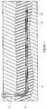
- FIG. 3Ais a perspective view of an embodiment of an apparatus for hydraulic fracing.
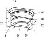
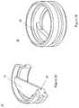
- FIGS. 3B to 3Dare perspective, close-up, cross-sectional views of an embodiment of a burst insert for use in an apparatus for hydraulic fracing.
- FIG. 3Eis a perspective close-up view of an embodiment of a burst insert for use in an apparatus for hydraulic fracing.
- a well 2is shown from a side elevation view where service/completion string 4 is downhole and proximate formation 6 .
- Fracing fluid 8can be pumped downhole through service/completion string 4 to fracing apparatus 10 .
- Apparatus 10can then release pressurised fracing fluid 8 to fracture formation 6 .
- FIG. 3Aan embodiment of apparatus 10 is shown comprising a main body 12 with a top connector 14 and a bottom connector 16 .
- Top and bottomas used herein are relative term and it would be understood by one skilled in the art that the orientation could be inverted without detracting from the function of apparatus. Similarly, top and bottom can be interchanged with terms such as left and right, or upstream and downstream, as required by the context of apparatus 10 .
- Main body 12can be tubular as to allow a fluid connection with a service/completion sting and allow fracing (or other) fluid to pass through body 12 .
- Main body 12can include one or more burst ports 17 which can be filled with a burst plug 18 .
- burst plug 18can be positioned towards the interior of, and blocking the opening of burst port 17 .
- Retention meanssuch as a burst plug retainer 20 and a seal 22 can be used to hold burst plug 18 in place.
- one or more ports 17can be located in a radially outwardly extending fin portion of the tubular member body 12 where an annulus can be formed between the tubular member and the wellbore can be reduced adjacent the fin portion.
- a debris barrier (or debris shield) 24can also be used to cover burst port 17 .
- debris barrier 24can be positioned towards the exterior of the opening of burst port 17 .
- a chambercan be defined between burst plug 18 and debris barrier 24 .
- Debris barrier 24can prevent debris and other substances from blocking burst port 17 .
- debris barrier 24can block cement and other debris from entering burst port 17 or main body 12 and cementing the apparatus 10 shut.
- debris barrier 24can be vented to provide a means of equalizing pressure between the chamber and an annulus formed between the tubular member and the wellbore.
- the chambercan be filed with a substance (such as a gel) for resisting entry of a wellbore fluid (such as cement) thereinto through the hole or vent.
- a substancesuch as a gel
- burst plug 18can be designed to include a burst plug membrane 26 and a fold-over ledge 28 , where membrane 26 can be thinner than ledge 28 .
- the membranecan formed integrally with the burst plug insert body at one end thereof.
- membrane 26can tear away from burst plug 18 around a portion of the perimeter of membrane 26 .
- the portion of membrane 26 attached to ledge 28can have a stronger connection and can be retained.
- the portion retained by ledge 28can remain intact and cause membrane 26 to fold outwardly onto ledge 28 .
- burst plug 18can open in a levered manner similar to a bottle cap, although a portion of membrane 26 remains connected to burst plug 18 .
- FIG. 3Cshows a first position, or mode, wherein burst plug 18 is in a burst position with membrane 26 partially disengaged from burst plug 18 thus allowing fluid to exit main body 12 .
- burst plug 18does not require an atmospheric chamber or a core that disengages.
- a burst plug assembly 18 and/or apparatus 10can be used in a method of hydraulic fracturing a formation in a well, wherein the assembly and/or apparatus is provided, fracture fluid is supplied, the membrane 26 is opened at a threshold pressure, fracture fluid flows past membrane 26 to contact the formation, and the formation in the well is fractured.
- the burst plug 18can be configured to disengage from insert body when the fluid pressure applied to the inner wall reaches or exceeds about 2000 psi, or at another desired pressure.
Landscapes
- Life Sciences & Earth Sciences (AREA)
- Engineering & Computer Science (AREA)
- Geology (AREA)
- Mining & Mineral Resources (AREA)
- Physics & Mathematics (AREA)
- Environmental & Geological Engineering (AREA)
- Fluid Mechanics (AREA)
- General Life Sciences & Earth Sciences (AREA)
- Geochemistry & Mineralogy (AREA)
- Containers And Packaging Bodies Having A Special Means To Remove Contents (AREA)
- Pressure Vessels And Lids Thereof (AREA)
- Pipe Accessories (AREA)
Abstract
Description
Claims (14)
Priority Applications (1)
| Application Number | Priority Date | Filing Date | Title |
|---|---|---|---|
| US16/159,288US10858909B2 (en) | 2013-12-27 | 2018-10-12 | Pressure activated completion tools, burst plugs, and methods of use |
Applications Claiming Priority (4)
| Application Number | Priority Date | Filing Date | Title |
|---|---|---|---|
| US201361921254P | 2013-12-27 | 2013-12-27 | |
| PCT/CA2014/000855WO2015095950A1 (en) | 2013-12-27 | 2014-12-01 | Pressure activated completion tools, burst plugs, and methods of use |
| US201615108227A | 2016-06-24 | 2016-06-24 | |
| US16/159,288US10858909B2 (en) | 2013-12-27 | 2018-10-12 | Pressure activated completion tools, burst plugs, and methods of use |
Related Parent Applications (2)
| Application Number | Title | Priority Date | Filing Date |
|---|---|---|---|
| US15/108,227ContinuationUS10125574B2 (en) | 2013-12-27 | 2014-12-01 | Pressure activated completion tools, burst plugs, and methods of use |
| PCT/CA2014/000855ContinuationWO2015095950A1 (en) | 2013-12-27 | 2014-12-01 | Pressure activated completion tools, burst plugs, and methods of use |
Publications (2)
| Publication Number | Publication Date |
|---|---|
| US20190040716A1 US20190040716A1 (en) | 2019-02-07 |
| US10858909B2true US10858909B2 (en) | 2020-12-08 |
Family
ID=53477240
Family Applications (2)
| Application Number | Title | Priority Date | Filing Date |
|---|---|---|---|
| US15/108,227Active2035-05-12US10125574B2 (en) | 2013-12-27 | 2014-12-01 | Pressure activated completion tools, burst plugs, and methods of use |
| US16/159,288Active2035-02-08US10858909B2 (en) | 2013-12-27 | 2018-10-12 | Pressure activated completion tools, burst plugs, and methods of use |
Family Applications Before (1)
| Application Number | Title | Priority Date | Filing Date |
|---|---|---|---|
| US15/108,227Active2035-05-12US10125574B2 (en) | 2013-12-27 | 2014-12-01 | Pressure activated completion tools, burst plugs, and methods of use |
Country Status (3)
| Country | Link |
|---|---|
| US (2) | US10125574B2 (en) |
| CA (2) | CA3113908C (en) |
| WO (1) | WO2015095950A1 (en) |
Families Citing this family (2)
| Publication number | Priority date | Publication date | Assignee | Title |
|---|---|---|---|---|
| CA2915624C (en) | 2015-12-18 | 2022-08-30 | Modern Wellbore Solutions Ltd. | Tool assembly and process for drilling branched or multilateral wells with whipstock |
| WO2017132744A1 (en)* | 2016-02-03 | 2017-08-10 | Tartan Completion Systems Inc. | Burst plug assembly with choke insert, fracturing tool and method of fracturing with same |
Citations (14)
| Publication number | Priority date | Publication date | Assignee | Title |
|---|---|---|---|---|
| US3908684A (en) | 1974-11-04 | 1975-09-30 | Black Sivalls & Bryson Inc | Rupture disk assembly |
| US4669626A (en)* | 1983-09-20 | 1987-06-02 | Continental Disc Corporation | Rupture disc with selectively positioned initial buckling |
| US5167337A (en) | 1990-01-09 | 1992-12-01 | Bs&B Safety Systems, Inc. | Scored reverse buckling rupture disk assembly |
| US5267666A (en) | 1993-01-19 | 1993-12-07 | Fike Corporation | Multiple-dome, scored, rupture disc |
| US5425424A (en) | 1994-02-28 | 1995-06-20 | Baker Hughes Incorporated | Casing valve |
| US5558114A (en)* | 1995-04-07 | 1996-09-24 | Oklahoma Safety Equipment Co. | Eccentric scored rupture disk assembly |
| WO1999014520A1 (en) | 1997-09-18 | 1999-03-25 | Continental Disc Corporation | Reverse buckling rupture disc |
| US20030121663A1 (en) | 2001-12-31 | 2003-07-03 | Xiaowei Weng | Method and apparatus for placement of multiple fractures in open hole wells |
| US7017767B2 (en)* | 2003-11-13 | 2006-03-28 | Fike Corporation | Non-fragmenting pressure relief apparatus |
| US20080178938A1 (en) | 2007-01-30 | 2008-07-31 | Fike Corporation | Rupture disc assembly that withstands much higher back pressures than actuation pressure |
| CA2692377A1 (en) | 2009-06-22 | 2010-09-16 | Trican Well Service Ltd. | Apparatus and method for stimulating subterranean formations |
| US20110192613A1 (en) | 2009-11-06 | 2011-08-11 | Weatherford/Lamb, Inc. | Cluster Opening Sleeves for Wellbore |
| CA2755848A1 (en) | 2011-10-19 | 2013-04-19 | Ten K Energy Service Ltd. | Insert assembly for downhole perforating apparatus |
| WO2014053062A1 (en) | 2012-10-02 | 2014-04-10 | Packers Plus Energy Services Inc. | Pressure sensitive cover for a fluid port in a downhole tool |
- 2014
- 2014-12-01CACA3113908Apatent/CA3113908C/enactiveActive
- 2014-12-01WOPCT/CA2014/000855patent/WO2015095950A1/enactiveApplication Filing
- 2014-12-01USUS15/108,227patent/US10125574B2/enactiveActive
- 2014-12-01CACA2935213Apatent/CA2935213C/enactiveActive
- 2018
- 2018-10-12USUS16/159,288patent/US10858909B2/enactiveActive
Patent Citations (18)
| Publication number | Priority date | Publication date | Assignee | Title |
|---|---|---|---|---|
| US3908684A (en) | 1974-11-04 | 1975-09-30 | Black Sivalls & Bryson Inc | Rupture disk assembly |
| US4669626A (en)* | 1983-09-20 | 1987-06-02 | Continental Disc Corporation | Rupture disc with selectively positioned initial buckling |
| US5167337A (en) | 1990-01-09 | 1992-12-01 | Bs&B Safety Systems, Inc. | Scored reverse buckling rupture disk assembly |
| US5267666A (en) | 1993-01-19 | 1993-12-07 | Fike Corporation | Multiple-dome, scored, rupture disc |
| US5425424A (en) | 1994-02-28 | 1995-06-20 | Baker Hughes Incorporated | Casing valve |
| US5558114A (en)* | 1995-04-07 | 1996-09-24 | Oklahoma Safety Equipment Co. | Eccentric scored rupture disk assembly |
| WO1999014520A1 (en) | 1997-09-18 | 1999-03-25 | Continental Disc Corporation | Reverse buckling rupture disc |
| US6006938A (en)* | 1997-09-18 | 1999-12-28 | Continental Disc Corporation | Enhanced reverse buckling rupture disc |
| US20030121663A1 (en) | 2001-12-31 | 2003-07-03 | Xiaowei Weng | Method and apparatus for placement of multiple fractures in open hole wells |
| US7017767B2 (en)* | 2003-11-13 | 2006-03-28 | Fike Corporation | Non-fragmenting pressure relief apparatus |
| US20080178938A1 (en) | 2007-01-30 | 2008-07-31 | Fike Corporation | Rupture disc assembly that withstands much higher back pressures than actuation pressure |
| CA2692377A1 (en) | 2009-06-22 | 2010-09-16 | Trican Well Service Ltd. | Apparatus and method for stimulating subterranean formations |
| US20120111566A1 (en) | 2009-06-22 | 2012-05-10 | Trican Well Service Ltd. | Apparatus and method for stimulating subterranean formations |
| US20110192613A1 (en) | 2009-11-06 | 2011-08-11 | Weatherford/Lamb, Inc. | Cluster Opening Sleeves for Wellbore |
| CA2755848A1 (en) | 2011-10-19 | 2013-04-19 | Ten K Energy Service Ltd. | Insert assembly for downhole perforating apparatus |
| US20140231064A1 (en) | 2011-10-19 | 2014-08-21 | Ten K Energy Services Ltd. | Insert Assembly for Downhole Perforating Apparatus |
| WO2014053062A1 (en) | 2012-10-02 | 2014-04-10 | Packers Plus Energy Services Inc. | Pressure sensitive cover for a fluid port in a downhole tool |
| US20150260012A1 (en)* | 2012-10-02 | 2015-09-17 | Packers Plus Energy Services Inc. | Pressure sensitive cover for a fluid port in a downhole tool |
Non-Patent Citations (2)
| Title |
|---|
| International Search Report issued by the Canadian Intellectual Property Office dated Feb. 16, 2015 in connection with International Patent Application No. PCT/CA2014/000855, 4 pages. |
| Written Opinion of the International Searching Authority issued by the Canadian Intellectual Property Office dated Feb. 16, 2015 in connection with International Patent Application No. PCT/CA2014/000855, 6 pages. |
Also Published As
| Publication number | Publication date |
|---|---|
| CA2935213C (en) | 2021-11-16 |
| US20160319636A1 (en) | 2016-11-03 |
| CA2935213A1 (en) | 2015-07-02 |
| CA3113908A1 (en) | 2015-07-02 |
| US20190040716A1 (en) | 2019-02-07 |
| WO2015095950A1 (en) | 2015-07-02 |
| US10125574B2 (en) | 2018-11-13 |
| CA3113908C (en) | 2023-10-24 |
Similar Documents
| Publication | Publication Date | Title |
|---|---|---|
| US10458221B2 (en) | Pressure activated completion tools and methods of use | |
| US9765594B2 (en) | Apparatus and method for stimulating subterranean formations | |
| EP2027360B2 (en) | Methods and devices for treating multiple-interval well bores | |
| US7954551B2 (en) | System and method for thru tubing deepening of gas lift | |
| US20130319668A1 (en) | Pumpable seat assembly and use for well completion | |
| US20130319682A1 (en) | Well completion using a pumpable seat assembly | |
| US10858909B2 (en) | Pressure activated completion tools, burst plugs, and methods of use | |
| AU2015201029B2 (en) | Apparatus and method for stimulating subterranean formations | |
| US10502033B2 (en) | Hydraulic stimulation method and corresponding hydraulic stimulation device | |
| DK201470817A1 (en) | Wellbore completion method | |
| CA2816458A1 (en) | Well completion using a pumpable seat assembly | |
| AU2013403420A1 (en) | Erosion resistant baffle for downhole wellbore tools | |
| CA2532295A1 (en) | Packer cups |
Legal Events
| Date | Code | Title | Description |
|---|---|---|---|
| AS | Assignment | Owner name:INTERRA ENERGY SERVICES LTD., CANADA Free format text:ASSIGNMENT OF ASSIGNORS INTEREST;ASSIGNOR:RAPID DESIGN GROUP INC.;REEL/FRAME:047152/0586 Effective date:20160914 Owner name:RAPID DESIGN GROUP INC., CANADA Free format text:ASSIGNMENT OF ASSIGNORS INTEREST;ASSIGNORS:ARABSKY, SERHIY;ARABSKY, VITALIY;REEL/FRAME:047152/0481 Effective date:20150108 | |
| FEPP | Fee payment procedure | Free format text:ENTITY STATUS SET TO UNDISCOUNTED (ORIGINAL EVENT CODE: BIG.); ENTITY STATUS OF PATENT OWNER: SMALL ENTITY | |
| FEPP | Fee payment procedure | Free format text:ENTITY STATUS SET TO SMALL (ORIGINAL EVENT CODE: SMAL); ENTITY STATUS OF PATENT OWNER: SMALL ENTITY | |
| STPP | Information on status: patent application and granting procedure in general | Free format text:DOCKETED NEW CASE - READY FOR EXAMINATION | |
| STPP | Information on status: patent application and granting procedure in general | Free format text:NON FINAL ACTION MAILED | |
| STPP | Information on status: patent application and granting procedure in general | Free format text:AWAITING TC RESP, ISSUE FEE PAYMENT VERIFIED | |
| STPP | Information on status: patent application and granting procedure in general | Free format text:PUBLICATIONS -- ISSUE FEE PAYMENT VERIFIED | |
| STCF | Information on status: patent grant | Free format text:PATENTED CASE | |
| MAFP | Maintenance fee payment | Free format text:PAYMENT OF MAINTENANCE FEE, 4TH YR, SMALL ENTITY (ORIGINAL EVENT CODE: M2551); ENTITY STATUS OF PATENT OWNER: SMALL ENTITY Year of fee payment:4 |