US10857567B2 - Analog to digital signal conversion in ultrasound device - Google Patents
Analog to digital signal conversion in ultrasound deviceDownload PDFInfo
- Publication number
- US10857567B2 US10857567B2US16/011,776US201816011776AUS10857567B2US 10857567 B2US10857567 B2US 10857567B2US 201816011776 AUS201816011776 AUS 201816011776AUS 10857567 B2US10857567 B2US 10857567B2
- Authority
- US
- United States
- Prior art keywords
- analog
- ultrasound
- digital
- electrical signal
- ultrasonic transducers
- Prior art date
- Legal status (The legal status is an assumption and is not a legal conclusion. Google has not performed a legal analysis and makes no representation as to the accuracy of the status listed.)
- Active, expires
Links
Images


Classifications
- B—PERFORMING OPERATIONS; TRANSPORTING
- B06—GENERATING OR TRANSMITTING MECHANICAL VIBRATIONS IN GENERAL
- B06B—METHODS OR APPARATUS FOR GENERATING OR TRANSMITTING MECHANICAL VIBRATIONS OF INFRASONIC, SONIC, OR ULTRASONIC FREQUENCY, e.g. FOR PERFORMING MECHANICAL WORK IN GENERAL
- B06B1/00—Methods or apparatus for generating mechanical vibrations of infrasonic, sonic, or ultrasonic frequency
- B06B1/02—Methods or apparatus for generating mechanical vibrations of infrasonic, sonic, or ultrasonic frequency making use of electrical energy
- B06B1/0207—Driving circuits
- B06B1/0215—Driving circuits for generating pulses, e.g. bursts of oscillations, envelopes
- B—PERFORMING OPERATIONS; TRANSPORTING
- B06—GENERATING OR TRANSMITTING MECHANICAL VIBRATIONS IN GENERAL
- B06B—METHODS OR APPARATUS FOR GENERATING OR TRANSMITTING MECHANICAL VIBRATIONS OF INFRASONIC, SONIC, OR ULTRASONIC FREQUENCY, e.g. FOR PERFORMING MECHANICAL WORK IN GENERAL
- B06B1/00—Methods or apparatus for generating mechanical vibrations of infrasonic, sonic, or ultrasonic frequency
- B06B1/02—Methods or apparatus for generating mechanical vibrations of infrasonic, sonic, or ultrasonic frequency making use of electrical energy
- B06B1/0292—Electrostatic transducers, e.g. electret-type
- B—PERFORMING OPERATIONS; TRANSPORTING
- B06—GENERATING OR TRANSMITTING MECHANICAL VIBRATIONS IN GENERAL
- B06B—METHODS OR APPARATUS FOR GENERATING OR TRANSMITTING MECHANICAL VIBRATIONS OF INFRASONIC, SONIC, OR ULTRASONIC FREQUENCY, e.g. FOR PERFORMING MECHANICAL WORK IN GENERAL
- B06B1/00—Methods or apparatus for generating mechanical vibrations of infrasonic, sonic, or ultrasonic frequency
- B06B1/02—Methods or apparatus for generating mechanical vibrations of infrasonic, sonic, or ultrasonic frequency making use of electrical energy
- B06B1/06—Methods or apparatus for generating mechanical vibrations of infrasonic, sonic, or ultrasonic frequency making use of electrical energy operating with piezoelectric effect or with electrostriction
- G—PHYSICS
- G01—MEASURING; TESTING
- G01S—RADIO DIRECTION-FINDING; RADIO NAVIGATION; DETERMINING DISTANCE OR VELOCITY BY USE OF RADIO WAVES; LOCATING OR PRESENCE-DETECTING BY USE OF THE REFLECTION OR RERADIATION OF RADIO WAVES; ANALOGOUS ARRANGEMENTS USING OTHER WAVES
- G01S15/00—Systems using the reflection or reradiation of acoustic waves, e.g. sonar systems
- G01S15/88—Sonar systems specially adapted for specific applications
- G01S15/89—Sonar systems specially adapted for specific applications for mapping or imaging
- G01S15/8906—Short-range imaging systems; Acoustic microscope systems using pulse-echo techniques
- G01S15/8909—Short-range imaging systems; Acoustic microscope systems using pulse-echo techniques using a static transducer configuration
- G01S15/8915—Short-range imaging systems; Acoustic microscope systems using pulse-echo techniques using a static transducer configuration using a transducer array
- G—PHYSICS
- G01—MEASURING; TESTING
- G01S—RADIO DIRECTION-FINDING; RADIO NAVIGATION; DETERMINING DISTANCE OR VELOCITY BY USE OF RADIO WAVES; LOCATING OR PRESENCE-DETECTING BY USE OF THE REFLECTION OR RERADIATION OF RADIO WAVES; ANALOGOUS ARRANGEMENTS USING OTHER WAVES
- G01S7/00—Details of systems according to groups G01S13/00, G01S15/00, G01S17/00
- G01S7/52—Details of systems according to groups G01S13/00, G01S15/00, G01S17/00 of systems according to group G01S15/00
- G01S7/523—Details of pulse systems
- G01S7/524—Transmitters
- G—PHYSICS
- G01—MEASURING; TESTING
- G01S—RADIO DIRECTION-FINDING; RADIO NAVIGATION; DETERMINING DISTANCE OR VELOCITY BY USE OF RADIO WAVES; LOCATING OR PRESENCE-DETECTING BY USE OF THE REFLECTION OR RERADIATION OF RADIO WAVES; ANALOGOUS ARRANGEMENTS USING OTHER WAVES
- G01S7/00—Details of systems according to groups G01S13/00, G01S15/00, G01S17/00
- G01S7/52—Details of systems according to groups G01S13/00, G01S15/00, G01S17/00 of systems according to group G01S15/00
- G01S7/523—Details of pulse systems
- G01S7/526—Receivers
- G01S7/53—Means for transforming coordinates or for evaluating data, e.g. using computers
- H—ELECTRICITY
- H03—ELECTRONIC CIRCUITRY
- H03M—CODING; DECODING; CODE CONVERSION IN GENERAL
- H03M1/00—Analogue/digital conversion; Digital/analogue conversion
- H03M1/12—Analogue/digital converters
- H03M1/34—Analogue value compared with reference values
- H03M1/38—Analogue value compared with reference values sequentially only, e.g. successive approximation type
- H03M1/46—Analogue value compared with reference values sequentially only, e.g. successive approximation type with digital/analogue converter for supplying reference values to converter
- H—ELECTRICITY
- H03—ELECTRONIC CIRCUITRY
- H03M—CODING; DECODING; CODE CONVERSION IN GENERAL
- H03M3/00—Conversion of analogue values to or from differential modulation
- H03M3/30—Delta-sigma modulation
- H03M3/322—Continuously compensating for, or preventing, undesired influence of physical parameters
- H—ELECTRICITY
- H03—ELECTRONIC CIRCUITRY
- H03M—CODING; DECODING; CODE CONVERSION IN GENERAL
- H03M3/00—Conversion of analogue values to or from differential modulation
- H03M3/30—Delta-sigma modulation
- H03M3/458—Analogue/digital converters using delta-sigma modulation as an intermediate step
- H03M3/464—Details of the digital/analogue conversion in the feedback path
- H—ELECTRICITY
- H03—ELECTRONIC CIRCUITRY
- H03M—CODING; DECODING; CODE CONVERSION IN GENERAL
- H03M1/00—Analogue/digital conversion; Digital/analogue conversion
- H03M1/66—Digital/analogue converters
- H03M1/74—Simultaneous conversion
- H03M1/742—Simultaneous conversion using current sources as quantisation value generators
Definitions
- the present applicationrelates to ultrasound devices and the conversion of analog ultrasound transducer signals into digital signals.
- Ultrasound probesoften include one or more ultrasound sensors which sense ultrasound signals and produce corresponding electrical signals.
- the electrical signalsare processed in the analog or digital domain.
- ultrasound imagesare generated from the processed electrical signals.
- an ultrasound apparatuscomprising an ultrasound sensor and an analog-to-digital converter (ADC) directly coupled to the ultrasound sensor to convert an analog output signal of the sensor into a digital signal.
- ADCanalog-to-digital converter
- the ultrasound devicemay lack analog processing circuitry electrically between the ultrasound sensor and the ADC.
- a method of operating an ultrasound devicecomprising directly converting an analog electrical signal output by a microfabricated ultrasonic transducer into a digital signal.
- an ultrasound on a chip devicecomprising analog-to-digital converters (ADCs) directly coupled to ultrasonic transducers and configured to convert analog output signals of the ultrasonic transducers into digital signals.
- ADCsanalog-to-digital converters
- an ultrasound on a chip devicecomprising a micromachined ultrasonic transducer (MUT), and an analog-to-digital converter (ADC) coupled to the MUT without intervening analog processing circuitry.
- MUTmicromachined ultrasonic transducer
- ADCanalog-to-digital converter
- an ultrasound devicecomprising a first substrate having a plurality of micromachined ultrasonic transducers integrated thereon, a second substrate having an analog-to-digital converter (ADC) integrated thereon, the ADC being coupled to an output of an ultrasonic transducer of the plurality of ultrasonic transducers without intervening analog processing circuitry, and transmit circuitry integrated on the second substrate, coupled to the plurality of ultrasonic transducers, and configured to control transmission of ultrasound signals by the plurality of ultrasonic transducers.
- ADCanalog-to-digital converter
- an ultrasound devicecomprising a first substrate having a plurality of micromachined ultrasonic transducers and transmit circuitry integrated thereon, the transmit circuitry coupled to the plurality of ultrasonic transducers and configured to control transmission of ultrasound signals by the plurality of ultrasonic transducers, and a second substrate having an analog-to-digital converter (ADC) integrated thereon, the ADC being coupled to an output of an ultrasonic transducer of the plurality of ultrasonic transducers without intervening analog processing circuitry.
- ADCanalog-to-digital converter
- a method of operating an ultrasound devicecomprising converting an analog electrical signal output by a microfabricated ultrasonic transducer into a digital signal without first performing processing of the analog electrical signal in an analog domain.
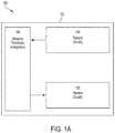
- FIG. 1Ais a block diagram of an ultrasound device including ultrasonic transducers, transmit circuitry, and receive circuitry on a single substrate.
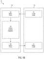
- FIG. 1Billustrates an alternative to the ultrasound device of FIG. 1A , in which the transmit circuitry and receive circuitry are divided among multiple substrates, according to a non-limiting embodiment of the present application.
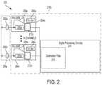
- FIG. 2illustrates a non-limiting example of an ultrasound device including ultrasonic transducers, transmit circuitry, and receive circuitry having an analog-to-digital converter (ADC) coupled to an ultrasonic transducer without intervening analog processing circuitry, according to a non-limiting embodiment of the present application.
- ADCanalog-to-digital converter
- FIG. 3illustrates an ultrasound signal chain in which an analog-to-digital converter is directly coupled to an ultrasonic transducer.
- FIG. 4illustrates an example of an ultrasonic transducer coupled with an ADC as may be implemented according to aspects of the present application.
- FIG. 5illustrates a non-limiting example of a digital-to-analog converter (DAC) having a controllable reference current.
- DACdigital-to-analog converter
- an ultrasound circuitincluding an ultrasonic transducer configured to produce an output (current or voltage) signal, and an analog-to-digital converter coupled directly to the ultrasonic transducer and configured to convert the analog signal from the ultrasonic transducer into a digital signal.
- the transducerproduces a current output signal, while in other embodiments the transducer produces a voltage output signal.
- the ADCmay be coupled to the ultrasonic transducer without intervening analog processing circuitry, thus allowing for power savings by avoiding the power associated with analog processing such as amplification and filtering.
- the circuitmay lack a distinct amplifier (e.g., a trans-impedance amplifier or “TIA”), time gain compensation (TGC) circuit, and analog-to-digital converter driver.
- TIAtrans-impedance amplifier
- TGCtime gain compensation
- analog-to-digital converter drivere.g., analog-to-digital converter driver.
- the ADCmay provide time gain compensation in at least some embodiments, thus providing an amplified digital signal representing the analog signal provided by the ultrasonic transducer.
- a method of processing electrical signals produced by an ultrasonic transducercomprises directly converting an analog electrical signal output by an ultrasonic transducer into a digital signal without first performing signal processing in the analog domain. Converting the analog signal to a digital signal may comprise performing time gain compensation. Subsequent to converting the electrical signal to a digital signal, further digital signal processing may optionally be performed.
- an ultrasound circuitincludes an ADC with built-in time gain compensation (TGC) functionality.
- the ADCmay include a digital-to-analog converter (DAC) with a controllable reference current.
- the reference currentmay be dynamically adjusted during a reception period in which the ultrasonic transducer receives an ultrasound signal, thus providing variable gain output from the ADC.
- DACdigital-to-analog converter
- the reference currentmay be dynamically adjusted during a reception period in which the ultrasonic transducer receives an ultrasound signal, thus providing variable gain output from the ADC.
- the ultrasonic transducersmay be microfabricated transducers, such as capacitive micromachined ultrasonic transducers (CMUTs), and the circuitry, such as the ADCs, may be integrated circuitry.
- CMUTscapacitive micromachined ultrasonic transducers
- the transducers and circuitrymay be integrated on the same substrate, on different substrates, or a combination. For example, some of the circuitry may be integrated on a substrate with the transducers, while other circuitry may be on a separate substrate.
- FIG. 1Ais a block diagram of an ultrasound device including ultrasonic transducers, transmit circuitry, and receive circuitry on a single substrate, according to a non-limiting embodiment.
- the ultrasound device 100comprises a substrate 102 , an ultrasonic transducer arrangement 104 , transmit circuitry 106 , and receive circuitry 108 .
- the substrate 102may be a semiconductor substrate, a complementary metal oxide semiconductor (CMOS) substrate (sometimes referred to herein simply as a “MOS” substrate) or other substrate on which the illustrated components may be fabricated.
- CMOScomplementary metal oxide semiconductor
- MOScomplementary metal oxide semiconductor
- the substrate 102may be a silicon substrate or a composite substrate comprising a MEMS substrate bonded with a MOS substrate.
- the ultrasonic transducers 102may be microfabricated ultrasonic transducers in at least some embodiments.
- CMUTspiezoelectric micromachined ultrasonic transducers (PMUTs) or other microfabricated ultrasonic transducers may be used.
- PMUTspiezoelectric micromachined ultrasonic transducers
- Any suitable number and arrangement of the ultrasonic transducersmay be used, as the various aspects of the present application are not limited in this respect.
- the arrangement of ultrasonic transducersmay include hundreds, thousands, tens of thousands, or hundreds of thousands of ultrasonic transducers.
- the transducersmay be arranged in an array or any other suitable arrangement.
- the transmit circuitry 106may include analog and/or digital circuitry for controlling transmission of ultrasound signals from the ultrasonic transducers. Examples of suitable transmit circuitry are illustrated in FIG. 2 and described further below.
- the transmit circuitrymay include a decoder circuit, waveform generator, and a pulser.
- the transmit circuitrymay include a decoder circuit, waveform generator, and a pulser.
- not all aspects of the present applicationinclude transmit circuitry, as some aspects of the present application are directed to an ultrasound receiver having receive circuitry for processing of received ultrasound signals.
- the receive circuitry 108may include analog and/or digital circuitry for processing ultrasound signals received by the ultrasonic transducers.
- the receive circuitryincludes an ADC and digital processing circuitry configured to process the digital signals produced by the ADC. Further examples are described below in connection with FIGS. 2-4 .
- FIG. 1Billustrates an alternative ultrasound device 120 to the ultrasound device 100 of FIG. 1A , in which the transmit circuitry and receive circuitry are divided among multiple substrates, according to a non-limiting embodiment of the present application.
- the ultrasound device 120includes two substrates, 122 a and 122 b , one or both of which may be any of the types of substrates described previously in connection with substrate 102 , or any other suitable substrates.
- the substrates 122 a and 122 bneed not be the same type of substrate as each other.
- analog transmit circuitrymay be on the substrate 122 a with the ultrasonic transducers, while digital transmit circuitry may be on the substrate 122 b .
- a receive switchmay be on the substrate 122 a
- digital receive circuitrymay be on the substrate 122 b .
- all the receive circuitry 108may be on either the substrate 122 a or 122 b
- the transmit circuitrymay be divided across substrates 122 a - 122 b .
- the transmit circuitrymay be entirely on either one of the substrates 122 a - 122 b , and the receive circuitry may be divided between the substrates.
- various combinationsare possible.
- FIG. 2illustrates a non-limiting example of an ultrasound device including ultrasonic transducers, transmit circuitry, and receive circuitry having an analog-to-digital converter (ADC) coupled to an ultrasonic transducer without intervening analog processing circuitry, according to a non-limiting embodiment of the present application.
- the ultrasound device 200includes N ultrasonic transducers 202 a . . . 202 n , wherein N is an integer.
- the ultrasonic transducersare sensors in some embodiments, producing electrical signals representing received ultrasound signals.
- the ultrasonic transducersmay also transmit ultrasound signals in some embodiments.
- the ultrasonic transducersmay be capacitive micromachined ultrasonic transducers (CMUTs) in some embodiments.
- the ultrasonic transducersmay be piezoelectric micromachined ultrasonic transducers (PMUTs) in some embodiments. Alternative types of ultrasonic transducers may be used in other embodiments.
- the ultrasound device 200further comprises N circuitry channels 204 a . . . 204 n .
- the circuitry channelsmay correspond to a respective ultrasonic transducer 202 a . . . 202 n .
- the number of ultrasonic transducers 202 a . . . 202 nmay be greater than the number of circuitry channels.
- the circuitry channels 204 a . . . 204 nmay include transmit circuitry, receive circuitry, or both.
- the transmit circuitrymay include transmit decoders 206 a . . . 206 n coupled to respective pulsers 208 a . . . 208 n .
- the pulsers 208 a . . . 208 nmay control the respective ultrasonic transducers 202 a . . . 202 n to emit ultrasound signals.
- the receive circuitry of the circuitry channels 204 a . . . 204 nmay receive the (analog) electrical signals output from respective ultrasonic transducers 202 a . . . 202 n .
- each circuitry channel 204 a . . . 204 nincludes a respective receive circuit 210 a . . . 210 n and an ADC 212 a . . . 212 n .
- the receive circuit 210 a . . . 210 nmay be controlled to activate/deactivate readout of an electrical signal from a given ultrasonic transducer 202 a . . . 202 n .
- . . 210 nis a switch. That is, in one embodiment the receive circuits are controllable switches which are switched during transmit mode to disconnect the ultrasonic transducers from the receive circuitry and during receive mode to connect the ultrasonic transducers to the receive circuitry. Alternatives to a switch may be employed to perform the same function. It should thus be appreciated that the receive circuits 210 a - 210 n may lack analog processing circuitry to process the analog signals produced by the respective ultrasonic transducers. Rather, the receive circuits 210 a - 210 n may, in some embodiments, simply control provision of the analog electrical signals produced by the ultrasonic transducers to the remainder of the receive circuitry.
- the receive circuitryfurther comprises ADCs 212 a - 212 n .
- An example of a suitable ADCis illustrated in FIG. 4 and described further below.
- the ADCsmay convert the analog electrical signals—which are current signals in at least some embodiments—produced by the ultrasonic transducers into digital signals.
- the ADCsmay have built-in TGC functionality, and thus may be considered a combined ADC and TGC circuit in some embodiments.
- the receive circuits 210 a - 210 nmay lack analog processing circuitry
- the ultrasound device 200represents an example of a device in which ADCs are coupled to the ultrasonic transducers without intervening analog processing circuitry.
- the analog output signals of the ultrasonic transducersmay be digitized without performing analog processing (processing in the analog domain), in at least some embodiments.
- Converting the analog signals produced by the ultrasonic transducers to digital signals without intervening analog processingmay provide various benefits. For example, power may be reduced by omitting typical analog processing stages, such as analog amplification and filtering. Also, real estate on a chip or other substrate may be conserved by omitting analog processing components, allowing for a reduction in the size of the ultrasound device compared to alternatives implementing analog processing circuitry.
- the ultrasound device 200may further comprise digital processing circuitry 214 , taking any suitable form and performing any desirable digital processing functions.
- the digital processing circuitrymay include a digital signal processor (DSP), a logic circuit, or any other suitable digital processing component.
- DSPdigital signal processor
- the digital processing circuitry 214is illustrated as being shared by various circuitry channels. However, this illustration is non-limiting, as alternatives are possible. For example, further digital processing stages of the digital processing circuitry 214 may be specific to one or more of the circuitry channels.
- the digital processing circuitry 214may perform decimation filtering owing to the lack of signal processing in the analog domain.
- a decimation filter 215may be included and may be coupled at the output of the ADCs 212 a - 212 n . While shown as part of the digital processing circuitry 214 , the decimation filter 215 may alternatively be considered to be electrically between an ADC and the digital processing circuitry 214 . That is, in some embodiments the decimation filter may be considered a separate component from the digital processing circuitry 214 .
- beamformingmay be performed on the output signals of the ADCs 212 a - 212 n prior to decimation with the decimation filter 215 .
- additional processing in the digital domainmay be performed to account for the analog characteristics of the circuit. For example, mapping of the digitized signal to the voltage as a function of time may be performed to account for the frequency response or other analog characteristics of the circuit.
- FIG. 2illustrates a number of components as part of a circuit of an ultrasound device
- the various aspects described hereinare not limited to the exact components or configuration of components illustrated.
- aspects of the present applicationmay lack the transmit circuitry, the receive circuits 210 a - 210 n , or other components.
- the components of FIG. 2may be located on a single substrate or on different substrates.
- the ultrasonic transducers 202 a . . . 202 nmay be on a first substrate 216 a and the remaining illustrated components may be on a second substrate 216 b .
- the first and/or second substratesmay be semiconductor substrates, such as silicon substrates, or any of the types of substrates described previously in connection with FIGS. 1A-1B .
- the components of FIG. 2may be on a single substrate.
- the ultrasonic transducers 202 a . . . 202 n and the illustrated circuitrymay be monolithically integrated on the same die (e.g., a semiconductor die, such as silicon). Such integration may be facilitated by using CMUTs as the ultrasonic transducers.
- the components of FIG. 1A, 1B , or 2form part of an ultrasound probe.
- the ultrasound probemay be handheld.
- the components of FIG. 1A, 1B , or 2form part of an ultrasound patch configured to be worn by a patient, or part of an ultrasound pill to be swallowed by a patient.
- FIG. 3illustrates a non-limiting example. It should be appreciated that FIG. 3 may represent a subset of components of the ultrasound device of FIG. 2 , namely the ultrasonic transducer, ADC, and further digital processing circuitry (e.g., digital processing circuitry 214 of FIG. 2 ).
- the ultrasound signal processing chain 300 of FIG. 3includes an ultrasonic transducer 302 , and ADC 304 , and digital processing circuitry 306 .
- the ADCmay be directly coupled the ultrasonic transducer, without intervening analog processing circuitry.
- the ultrasonic transducer 302may be any of the types described previously herein in connection with FIGS. 1A, 1B, and 2 .
- the ADC 304may be a sigma delta ADC, such as a sigma delta continuous time ADC. A non-limiting example is illustrated in FIG. 4 and described further below.
- the ADC 304may optionally include built-in TGC functionality, such that the ADC 304 may be considered a combined ADC and TGC circuit.
- an ADCmay be provided for a respective ultrasonic transducer.
- an ADCmay be shared among multiple (two or more) ultrasonic transducers.
- the digital processing circuitry 306may be any suitable digital processing circuitry, including any of the types described previously in connection with digital processing circuitry 214 of FIG. 2 .
- FIG. 4illustrates a non-limiting example of a suitable ADC 400 coupled directly to an ultrasonic transducer, according to a non-limiting embodiment of the present application.
- the ADC 400represents an example of the implementation of any one of ADCs 212 a - 212 n .
- the ultrasonic transducer 402is represented schematically as a capacitor C and current source I 1 .
- the ultrasonic transducermay be, for example, a CMUT which produces a current output signal, represented by the current source.
- the ADC of FIG. 4may include a summer (or, more generally, a combiner) 404 , a loop filter 406 , a quantizer 408 , and a digital-to-analog converter (DAC) 410 .
- the ADCmay receive an analog current signal from the ultrasonic transducer 402 , filter the signal with filter 406 , digitize the signal with the quantizer 408 and output the digital signal 412 .
- the digital signalmay also be fed back to the summer 404 via the DAC 410 to be combined with the analog signal from the ultrasonic transducer.
- the summer 404may be any suitable type of combiner component. In at least some embodiments, the summer 404 subtracts the current output by the DAC 410 from the current output by the ultrasonic transducer 402 . Thus, any suitable circuitry for performing such a subtraction may be implemented. Because the output of the transducer may be a current and the output of the ADC 400 may also be a current, one implementation of the summer 404 is simply a node. That is, the summer 404 may not be a distinct component in some embodiments, but rather the output of the DAC 410 may simply be tied to the output of the ultrasonic transducer 402 .
- the loop filter 406may be any suitable type of loop filter.
- a first order filter, second order filter, or third order filtermay be implemented.
- the loop filtermay be a low pass filter (LPF) or a bandpass filter (BPF), and may be implemented using one or more operational amplifiers (op-amps), a voltage controlled oscillator (VCO), or a combination thereof.
- the loop filter 406may be a continuous time filter, which may provide the benefit of anti-aliasing protection. Still further alternatives are possible.
- the quantizer 408may be any suitable quantizer, such as a 1-bit or 2-bit quantizer.
- a switch 409is illustrated for completeness, since such a switch is sometimes implemented as part of the quantization process of the quantizer 408 .
- the switchmay be controlled by a clock signal, CLK, which may be any suitable clocking signal of any suitable frequency.
- the DAC 410may be any suitable DAC for converting the digital signal output by the quantizer 408 to an analog signal for comparison with the analog signal from the ultrasonic transducer 402 .
- the inventorshave appreciated that in some embodiments it may be desirable to provide time gain compensation for the output signal of the ultrasonic transducer. Typically, an ultrasound signal attenuates with time, and thus time gain compensation may be performed to facilitate processing and analysis of a received ultrasound signal.
- aspects of the present applicationutilize a controllable DAC to provide variable gain.
- the DAC 410may have a controllable (or “adjustable” or “programmable”) reference current.
- FIG. 5A non-limiting example of a suitable DAC with a controllable current is illustrated in FIG. 5 and described further below.
- Increasing the reference currentmay result in greater output signal from the DAC.
- aspects of the present applicationadjust or vary the DAC reference current during the time period corresponding to reception of an ultrasound signal by the ultrasonic transducer 402 .
- the gain of the DAC, and thus the ADCmay be increased over time, providing TGC functionality without a distinct TGC circuit.
- further processing of the DAC output signalis provided to map the output digital code of the ADC to an appropriate value for the given reference current value.
- FIG. 5illustrates a non-limiting example of a DAC 500 having a controllable reference current.
- the DACis a one-bit DAC, but other embodiments may employ a multi-bit DAC.
- the DAC 500includes switches SW 1 , SW 2 . . . SWn, current sources I 1 , I 2 . . . In, switches S 1 and S 2 , switches Sd 1 , Sd 2 . . . Sdn, and current sources Id 1 , Id 2 . . . Idn.
- a supplyis provided at node 502 .
- the outputis taken from node 504 .
- Suitable control signalsmay be provided to the switches SW 1 -SWn and Sd 1 -Sdn to provide a desired reference current (+Iref or ⁇ Iref) as described above in connection with DAC 410 .
- a desired reference current (+Iref or ⁇ Iref)as described above in connection with DAC 410 .
- S 1is ON it produces +Iref and if S 2 is ON it produces ⁇ Iref.
- TGC functionalitymay be realized.
- other DACsincluding multi-bit DACs may be employed in alternative embodiments.
- an ADCmay be provided which filters (via H(s) loop filter 406 ), amplifies, and digitizes an analog (current) signal from an ultrasonic transducer.
- analog amplification and filtering stagesmay be omitted, and the ADC may be coupled directly (or through a switch or other non-processing component) to the ultrasonic transducer.
- the power and real estate associated with analog processing componentsmay be avoided in at least some embodiments.
- some aspectsmay be embodied as one or more methods.
- the acts performed as part of the method(s)may be ordered in any suitable way. Accordingly, embodiments may be constructed in which acts are performed in an order different than illustrated, which may include performing some acts simultaneously, even though shown as sequential acts in illustrative embodiments.
- the phrase “at least one,” in reference to a list of one or more elements,should be understood to mean at least one element selected from any one or more of the elements in the list of elements, but not necessarily including at least one of each and every element specifically listed within the list of elements and not excluding any combinations of elements in the list of elements.
- the term “between” used in a numerical contextis to be inclusive unless indicated otherwise.
- “between A and B”includes A and B unless indicated otherwise.
Landscapes
- Engineering & Computer Science (AREA)
- Radar, Positioning & Navigation (AREA)
- Remote Sensing (AREA)
- Physics & Mathematics (AREA)
- Computer Networks & Wireless Communication (AREA)
- General Physics & Mathematics (AREA)
- Acoustics & Sound (AREA)
- Mechanical Engineering (AREA)
- Theoretical Computer Science (AREA)
- Ultra Sonic Daignosis Equipment (AREA)
- Transducers For Ultrasonic Waves (AREA)
Abstract
Description
Claims (16)
Priority Applications (1)
| Application Number | Priority Date | Filing Date | Title |
|---|---|---|---|
| US16/011,776US10857567B2 (en) | 2017-06-20 | 2018-06-19 | Analog to digital signal conversion in ultrasound device |
Applications Claiming Priority (2)
| Application Number | Priority Date | Filing Date | Title |
|---|---|---|---|
| US201762522625P | 2017-06-20 | 2017-06-20 | |
| US16/011,776US10857567B2 (en) | 2017-06-20 | 2018-06-19 | Analog to digital signal conversion in ultrasound device |
Publications (2)
| Publication Number | Publication Date |
|---|---|
| US20180361431A1 US20180361431A1 (en) | 2018-12-20 |
| US10857567B2true US10857567B2 (en) | 2020-12-08 |
Family
ID=64656584
Family Applications (1)
| Application Number | Title | Priority Date | Filing Date |
|---|---|---|---|
| US16/011,776Active2039-05-23US10857567B2 (en) | 2017-06-20 | 2018-06-19 | Analog to digital signal conversion in ultrasound device |
Country Status (9)
| Country | Link |
|---|---|
| US (1) | US10857567B2 (en) |
| EP (1) | EP3642960A4 (en) |
| JP (1) | JP2020524428A (en) |
| KR (1) | KR20200018659A (en) |
| CN (1) | CN110771044A (en) |
| AU (1) | AU2018289344A1 (en) |
| CA (1) | CA3065214A1 (en) |
| TW (1) | TW201905491A (en) |
| WO (1) | WO2018236786A1 (en) |
Cited By (8)
| Publication number | Priority date | Publication date | Assignee | Title |
|---|---|---|---|---|
| US11005435B2 (en) | 2017-06-20 | 2021-05-11 | Butterfly Network, Inc. | Amplifier with built in time gain compensation for ultrasound applications |
| US11324484B2 (en) | 2017-06-20 | 2022-05-10 | Bfly Operations, Inc. | Multi-stage trans-impedance amplifier (TIA) for an ultrasound device |
| US11504093B2 (en) | 2021-01-22 | 2022-11-22 | Exo Imaging, Inc. | Equalization for matrix based line imagers for ultrasound imaging systems |
| WO2023132829A1 (en) | 2022-01-06 | 2023-07-13 | Exo Imaging, Inc. | Full-array digital 3d ultrasound imaging system integrated with a matrix array transducer |
| US11808897B2 (en) | 2020-10-05 | 2023-11-07 | Bfly Operations, Inc. | Methods and apparatuses for azimuthal summing of ultrasound data |
| US11815492B2 (en) | 2020-04-16 | 2023-11-14 | Bfly Operations, Inc. | Methods and circuitry for built-in self-testing of circuitry and/or transducers in ultrasound devices |
| WO2024054589A1 (en) | 2022-09-09 | 2024-03-14 | Exo Imaging, Inc. | Coherent matrix of digital imaging systems on chip |
| US12156762B2 (en) | 2021-04-01 | 2024-12-03 | Bfly Operations, Inc. | Apparatuses and methods for configuring ultrasound devices |
Families Citing this family (6)
| Publication number | Priority date | Publication date | Assignee | Title |
|---|---|---|---|---|
| CA3064584A1 (en) | 2017-06-20 | 2018-12-27 | Butterfly Network, Inc. | Single-ended trans-impedance amplifier (tia) for ultrasound device |
| CN110771044A (en)* | 2017-06-20 | 2020-02-07 | 蝴蝶网络有限公司 | Conversion of analog signals to digital signals in ultrasound devices |
| US11558062B2 (en) | 2019-07-25 | 2023-01-17 | Bfly Operations, Inc. | Methods and apparatuses for turning on and off an ADC driver in an ultrasound device |
| WO2021055721A1 (en) | 2019-09-19 | 2021-03-25 | Butterfly Network, Inc. | Symmetric receiver switch for ultrasound devices |
| CN114868033A (en)* | 2019-12-17 | 2022-08-05 | 布弗莱运营公司 | Method and apparatus for encapsulating an on-chip ultrasound device |
| JP7549773B2 (en)* | 2020-03-31 | 2024-09-12 | 株式会社ジェイ・エム・エス | Rods, wipes, and cleaning kit |
Citations (73)
| Publication number | Priority date | Publication date | Assignee | Title |
|---|---|---|---|---|
| US4829491A (en) | 1984-07-12 | 1989-05-09 | Siemens Aktiengesellschaft | Phased-array equipment |
| US5844445A (en) | 1995-10-27 | 1998-12-01 | Hitachi, Ltd. | Feedback type pre-amplifier |
| US20010038450A1 (en) | 2000-03-31 | 2001-11-08 | Mccaffrey John T. | Methods and apparatus to improve the sensitivity and reproducibility of bioluminescent analytical methods |
| US6356152B1 (en) | 1999-07-14 | 2002-03-12 | Texas Instruments Incorporated | Amplifier with folded super-followers |
| US6404281B1 (en) | 2000-11-14 | 2002-06-11 | Sirenza Microdevices, Inc. | Wide dynamic range transimpedance amplifier |
| US20040260214A1 (en) | 2003-06-17 | 2004-12-23 | Ebr Systems, Inc. | Methods and systems for vibrational treatment of cardiac arrhythmias |
| US20050148878A1 (en)* | 2003-12-19 | 2005-07-07 | Siemens Medical Solutions Usa, Inc.. | Probe based digitizing or compression system and method for medical ultrasound |
| US20060161359A1 (en) | 2004-12-29 | 2006-07-20 | Endress + Hauser Flowtec Ag | Field device electronics fed by an external electrical energy supply |
| US20060164169A1 (en) | 2003-07-30 | 2006-07-27 | Tropian, Inc. | Power distribution and biasing in RF switch-mode power amplifiers |
| US20070001764A1 (en) | 2005-06-30 | 2007-01-04 | Yunteng Huang | Signal dependent biasing scheme for an amplifier |
| US20070038091A1 (en) | 2005-08-09 | 2007-02-15 | Kabushiki Kaisha Toshiba | Ultrasonic diagnostic apparatus and ultrasonic transmission method |
| WO2007096636A1 (en) | 2006-02-24 | 2007-08-30 | Wolfson Microelectronics Plc. | Mems device |
| US20070232917A1 (en)* | 2006-03-29 | 2007-10-04 | Medison Co., Ltd. | Digital beamforming apparatus with a sigma-delta a/d converter |
| US20070242567A1 (en) | 2005-12-07 | 2007-10-18 | Daft Christopher M | Multi-dimensional CMUT array with integrated beamformation |
| US20070287923A1 (en) | 2006-05-15 | 2007-12-13 | Charles Adkins | Wrist plethysmograph |
| US7313053B2 (en) | 2003-03-06 | 2007-12-25 | General Electric Company | Method and apparatus for controlling scanning of mosaic sensor array |
| US7449958B1 (en) | 2005-08-17 | 2008-11-11 | Marvell International Ltd. | Open loop DC control for a transimpedance feedback amplifier |
| US20090002073A1 (en) | 2007-06-29 | 2009-01-01 | Chang Sun Kim | Wideband Variable Gain Amplifier With Clipping Function |
| US20090157130A1 (en) | 2007-11-16 | 2009-06-18 | Ruse Technologies, Llc | Apparatus and method for treating atrial fibrillation and atrial tachycardia |
| US20090184853A1 (en) | 2008-01-21 | 2009-07-23 | Texas Instruments Incorporated | Analog to digital converter with improved input overload recovery |
| US20090250729A1 (en) | 2004-09-15 | 2009-10-08 | Lemmerhirt David F | Capacitive micromachined ultrasonic transducer and manufacturing method |
| US7605660B1 (en) | 2007-11-12 | 2009-10-20 | Rf Micro Devices, Inc. | Linear multi-stage transimpedance amplifier |
| US20100152587A1 (en) | 2008-12-17 | 2010-06-17 | General Electric Company | Systems and methods for operating a two-dimensional transducer array |
| US20100166228A1 (en) | 2008-12-30 | 2010-07-01 | Colin Findlay Steele | Apparatus and method for biasing a transducer |
| US20100234736A1 (en) | 2009-03-11 | 2010-09-16 | Volcano Corporation | Rotational intravascular ultrasound probe with an active spinning element |
| US20100237807A1 (en) | 2009-03-18 | 2010-09-23 | Lemmerhirt David F | System and method for biasing cmut elements |
| US20100246648A1 (en) | 2009-02-12 | 2010-09-30 | David Gimenez Rocamora | External AC-DC Coupling for Communication Interfaces |
| US20100317972A1 (en) | 2009-06-16 | 2010-12-16 | Charles Edward Baumgartner | Ultrasound transducer with improved acoustic performance |
| US20100327695A1 (en) | 2009-06-30 | 2010-12-30 | Avago Technologies Wireless Ip (Singapore) Pte. Ltd. | Multi-frequency acoustic array |
| US20110115562A1 (en) | 2009-11-16 | 2011-05-19 | Tyco Healthcare Group Lp | Class Resonant-H Electrosurgical Generators |
| US20110130109A1 (en) | 2009-12-02 | 2011-06-02 | Kabushiki Kaisha Toshiba | Differential amplifier circuit and wireless receiving apparatus |
| US20110148682A1 (en) | 2009-12-19 | 2011-06-23 | General Electric Company | Predictive analog-to-digital converter and methods thereof |
| US20110205096A1 (en) | 2009-07-09 | 2011-08-25 | Intersil Americas Inc. | Systems including a programmable segmented dac and methods for use therewith |
| US20120163129A1 (en)* | 2010-12-23 | 2012-06-28 | Analog Devices, Inc. | Acoustic Transducer Chip |
| US20120265491A1 (en) | 2011-04-18 | 2012-10-18 | Olympus Ndt Inc. | Non-destructive inspection instrument employing multiple sensor technologies in an integral enclosure |
| US20130056622A1 (en) | 2010-04-02 | 2013-03-07 | Centre Nationla De La Recherch Scientifique (C.N.R.S.) | Analog electronic circuit for processing a light signal, and corresponding processing system and method |
| US20130064043A1 (en) | 2011-03-04 | 2013-03-14 | Georgia Tech Research Corporation | Compact, energy-efficient ultrasound imaging probes using cmut arrays with integrated electronics |
| CN103607130A (en) | 2013-11-26 | 2014-02-26 | 徐州中矿大传动与自动化有限公司 | Three-level pulse extension control method and three-level pulse extension device of DSPACE based on FPGA |
| US8662395B2 (en) | 2008-10-14 | 2014-03-04 | Dolphitech As | Ultrasonic imaging apparatus for reading and decoding machine-readable matrix symbols |
| US20140088425A1 (en) | 2012-09-27 | 2014-03-27 | Industrial Technology Research Institute | Single chip and handheld electronic device |
| US20140240482A1 (en) | 2011-09-15 | 2014-08-28 | Hitachi Medical Corporation | Ultrasound imaging apparatus |
| US20140288428A1 (en) | 2013-03-15 | 2014-09-25 | Butterfly Network, Inc. | Monolithic ultrasonic imaging devices, systems and methods |
| US8852103B2 (en) | 2011-10-17 | 2014-10-07 | Butterfly Network, Inc. | Transmissive imaging and related apparatus and methods |
| TW201445554A (en) | 2013-04-04 | 2014-12-01 | Semiconductor Energy Lab | Pulse generation circuit and semiconductor device |
| US20150032002A1 (en) | 2013-07-23 | 2015-01-29 | Butterfly Network, Inc. | Interconnectable ultrasound transducer probes and related methods and apparatus |
| US20150041317A1 (en) | 2013-08-07 | 2015-02-12 | Xagenic Inc. | Precision bipolar current-mode digital-to-analog converter |
| US20150086221A1 (en) | 2013-09-25 | 2015-03-26 | Inphi Corporation | Self biased dual mode differential cmos tia for 400g fiber optic links |
| US20150145597A1 (en) | 2013-11-25 | 2015-05-28 | Taiwan Semiconductor Manufacturing Company, Ltd. | Multi-stage transimpedance amplifier and a method of using the same |
| US20150280662A1 (en) | 2014-03-27 | 2015-10-01 | Texas Instruments Incorporated | Time gain compensation circuit in an ultrasound receiver |
| US20150298170A1 (en)* | 2014-04-18 | 2015-10-22 | Butterfly Network, Inc. | Ultrasonic Transducers in Complementary Metal Oxide Semiconductor (CMOS) Wafers and Related Apparatus and Methods |
| US20150297193A1 (en) | 2014-04-18 | 2015-10-22 | Butterfly Network, Inc. | Ultrasonic Imaging Compression Methods and Apparatus |
| WO2015189149A1 (en) | 2014-06-12 | 2015-12-17 | Koninklijke Philips N.V. | Ultrasound transducer assembly |
| US20150374335A1 (en) | 2013-03-07 | 2015-12-31 | Sharp Kabushiki Kaisha | Ultrasound sensor element, ultrasound sensor array assembly, ultrasound transmit sensor element, imaging device, ultrasound transducer, and method of performing an ultrasound scan |
| US9229097B2 (en) | 2014-04-18 | 2016-01-05 | Butterfly Network, Inc. | Architecture of single substrate ultrasonic imaging devices, related apparatuses, and methods |
| US20160228099A1 (en) | 2013-09-19 | 2016-08-11 | Koninklijke Philips N.V. | Tgc controls for an ultrasonic diagnostic imaging systme |
| US9473136B1 (en) | 2015-12-02 | 2016-10-18 | Butterfly Network, Inc. | Level shifter and related methods and apparatus |
| US9492144B1 (en) | 2015-12-02 | 2016-11-15 | Butterfly Network, Inc. | Multi-level pulser and related apparatus and methods |
| US20170026011A1 (en) | 2015-07-20 | 2017-01-26 | Mindspeed Technologies, Inc. | Transimpedance Amplifier with Bandwidth Extender |
| US20170160239A1 (en) | 2015-12-02 | 2017-06-08 | Butterfly Network, Inc. | Time gain compensation circuit and related apparatus and methods |
| US20170163225A1 (en) | 2015-12-02 | 2017-06-08 | Butterfly Network, Inc. | Trans-impedance amplifier for ultrasound device and related apparatus and methods |
| US20170160388A1 (en) | 2015-12-02 | 2017-06-08 | Butterfly Network, Inc. | Ultrasound receiver circuitry and related apparatus and methods |
| US20170163276A1 (en) | 2015-12-02 | 2017-06-08 | Butterfly Network, Inc. | Asynchronous successive approximation analog-to-digital converter and related methods and apparatus |
| US20170169899A1 (en) | 2014-02-03 | 2017-06-15 | Cornell University | Piezoelectric and logic integrated delay line memory |
| WO2017097968A1 (en) | 2015-12-10 | 2017-06-15 | Koninklijke Philips N.V. | An ultrasound imaging system probe and system, and an imaging method |
| US20170202541A1 (en) | 2016-01-15 | 2017-07-20 | Butterfly Network, Inc. | Ultrasound signal processing circuitry and related apparatus and methods |
| US20180070925A1 (en) | 2016-09-13 | 2018-03-15 | Butterfly Network, Inc. | Analog-to-digital drive circuitry having built-in time gain compensation functionality for ultrasound applications |
| US10082565B2 (en) | 2016-03-31 | 2018-09-25 | Butterfly Network, Inc. | Multilevel bipolar pulser |
| US10116263B1 (en) | 2017-05-16 | 2018-10-30 | Inphi Corporation | Method and device for TIA overload control in low power applications |
| US20180367111A1 (en) | 2017-06-20 | 2018-12-20 | Butterfly Network, Inc. | Amplifier with built in time gain compensation for ultrasound applications |
| US20180360426A1 (en) | 2017-06-20 | 2018-12-20 | Butterfly Network, Inc. | Multi-stage trans-impedance amplifier (tia) for an ultrasound device |
| US20180361431A1 (en)* | 2017-06-20 | 2018-12-20 | Butterfly Network, Inc. | Analog to digital signal conversion in ultrasound device |
| US20180367110A1 (en) | 2017-06-20 | 2018-12-20 | Butterfly Network, Inc. | Single-ended trans-impedance amplifier (tia) for ultrasound device |
| US20190050618A1 (en) | 2017-08-09 | 2019-02-14 | The Board Of Trustees Of The Leland Stanford Junior University | Interactive biometric touch scanner |
Family Cites Families (4)
| Publication number | Priority date | Publication date | Assignee | Title |
|---|---|---|---|---|
| GB0821940D0 (en)* | 2008-12-01 | 2009-01-07 | Ntnu Technology Transfer As | Analogue to digital converter |
| US9941817B2 (en)* | 2010-10-15 | 2018-04-10 | Hitachi, Ltd. | Ultrasonic transducer and ultrasonic diagnostic equipment using the same |
| US8587464B2 (en)* | 2012-01-09 | 2013-11-19 | International Business Machines Corporation | Off-line gain calibration in a time-interleaved analog-to-digital converter |
| EP3733309A1 (en)* | 2019-04-30 | 2020-11-04 | Koninklijke Philips N.V. | Capacitive micro-machined ultrasound transducer (cmut) devices |
- 2018
- 2018-06-19CNCN201880039697.XApatent/CN110771044A/enactivePending
- 2018-06-19TWTW107121007Apatent/TW201905491A/enunknown
- 2018-06-19CACA3065214Apatent/CA3065214A1/enactivePending
- 2018-06-19AUAU2018289344Apatent/AU2018289344A1/ennot_activeAbandoned
- 2018-06-19USUS16/011,776patent/US10857567B2/enactiveActive
- 2018-06-19KRKR1020207001476Apatent/KR20200018659A/ennot_activeWithdrawn
- 2018-06-19JPJP2019565387Apatent/JP2020524428A/enactivePending
- 2018-06-19WOPCT/US2018/038166patent/WO2018236786A1/ennot_activeCeased
- 2018-06-19EPEP18820178.4Apatent/EP3642960A4/ennot_activeWithdrawn
Patent Citations (102)
| Publication number | Priority date | Publication date | Assignee | Title |
|---|---|---|---|---|
| US4829491A (en) | 1984-07-12 | 1989-05-09 | Siemens Aktiengesellschaft | Phased-array equipment |
| US5844445A (en) | 1995-10-27 | 1998-12-01 | Hitachi, Ltd. | Feedback type pre-amplifier |
| US6356152B1 (en) | 1999-07-14 | 2002-03-12 | Texas Instruments Incorporated | Amplifier with folded super-followers |
| US20010038450A1 (en) | 2000-03-31 | 2001-11-08 | Mccaffrey John T. | Methods and apparatus to improve the sensitivity and reproducibility of bioluminescent analytical methods |
| US6404281B1 (en) | 2000-11-14 | 2002-06-11 | Sirenza Microdevices, Inc. | Wide dynamic range transimpedance amplifier |
| US7313053B2 (en) | 2003-03-06 | 2007-12-25 | General Electric Company | Method and apparatus for controlling scanning of mosaic sensor array |
| US20040260214A1 (en) | 2003-06-17 | 2004-12-23 | Ebr Systems, Inc. | Methods and systems for vibrational treatment of cardiac arrhythmias |
| US20060164169A1 (en) | 2003-07-30 | 2006-07-27 | Tropian, Inc. | Power distribution and biasing in RF switch-mode power amplifiers |
| US20050148878A1 (en)* | 2003-12-19 | 2005-07-07 | Siemens Medical Solutions Usa, Inc.. | Probe based digitizing or compression system and method for medical ultrasound |
| US20090250729A1 (en) | 2004-09-15 | 2009-10-08 | Lemmerhirt David F | Capacitive micromachined ultrasonic transducer and manufacturing method |
| US20060161359A1 (en) | 2004-12-29 | 2006-07-20 | Endress + Hauser Flowtec Ag | Field device electronics fed by an external electrical energy supply |
| US20070001764A1 (en) | 2005-06-30 | 2007-01-04 | Yunteng Huang | Signal dependent biasing scheme for an amplifier |
| US20070038091A1 (en) | 2005-08-09 | 2007-02-15 | Kabushiki Kaisha Toshiba | Ultrasonic diagnostic apparatus and ultrasonic transmission method |
| US7449958B1 (en) | 2005-08-17 | 2008-11-11 | Marvell International Ltd. | Open loop DC control for a transimpedance feedback amplifier |
| US20070242567A1 (en) | 2005-12-07 | 2007-10-18 | Daft Christopher M | Multi-dimensional CMUT array with integrated beamformation |
| WO2007096636A1 (en) | 2006-02-24 | 2007-08-30 | Wolfson Microelectronics Plc. | Mems device |
| US20070232917A1 (en)* | 2006-03-29 | 2007-10-04 | Medison Co., Ltd. | Digital beamforming apparatus with a sigma-delta a/d converter |
| US20070287923A1 (en) | 2006-05-15 | 2007-12-13 | Charles Adkins | Wrist plethysmograph |
| US20090002073A1 (en) | 2007-06-29 | 2009-01-01 | Chang Sun Kim | Wideband Variable Gain Amplifier With Clipping Function |
| US7605660B1 (en) | 2007-11-12 | 2009-10-20 | Rf Micro Devices, Inc. | Linear multi-stage transimpedance amplifier |
| US20090157130A1 (en) | 2007-11-16 | 2009-06-18 | Ruse Technologies, Llc | Apparatus and method for treating atrial fibrillation and atrial tachycardia |
| US20090184853A1 (en) | 2008-01-21 | 2009-07-23 | Texas Instruments Incorporated | Analog to digital converter with improved input overload recovery |
| US8662395B2 (en) | 2008-10-14 | 2014-03-04 | Dolphitech As | Ultrasonic imaging apparatus for reading and decoding machine-readable matrix symbols |
| US20100152587A1 (en) | 2008-12-17 | 2010-06-17 | General Electric Company | Systems and methods for operating a two-dimensional transducer array |
| US20100166228A1 (en) | 2008-12-30 | 2010-07-01 | Colin Findlay Steele | Apparatus and method for biasing a transducer |
| US20100246648A1 (en) | 2009-02-12 | 2010-09-30 | David Gimenez Rocamora | External AC-DC Coupling for Communication Interfaces |
| US20100234736A1 (en) | 2009-03-11 | 2010-09-16 | Volcano Corporation | Rotational intravascular ultrasound probe with an active spinning element |
| US20100237807A1 (en) | 2009-03-18 | 2010-09-23 | Lemmerhirt David F | System and method for biasing cmut elements |
| US20100317972A1 (en) | 2009-06-16 | 2010-12-16 | Charles Edward Baumgartner | Ultrasound transducer with improved acoustic performance |
| US20100327695A1 (en) | 2009-06-30 | 2010-12-30 | Avago Technologies Wireless Ip (Singapore) Pte. Ltd. | Multi-frequency acoustic array |
| US20110205096A1 (en) | 2009-07-09 | 2011-08-25 | Intersil Americas Inc. | Systems including a programmable segmented dac and methods for use therewith |
| US20110115562A1 (en) | 2009-11-16 | 2011-05-19 | Tyco Healthcare Group Lp | Class Resonant-H Electrosurgical Generators |
| US20110130109A1 (en) | 2009-12-02 | 2011-06-02 | Kabushiki Kaisha Toshiba | Differential amplifier circuit and wireless receiving apparatus |
| US20110148682A1 (en) | 2009-12-19 | 2011-06-23 | General Electric Company | Predictive analog-to-digital converter and methods thereof |
| US20130056622A1 (en) | 2010-04-02 | 2013-03-07 | Centre Nationla De La Recherch Scientifique (C.N.R.S.) | Analog electronic circuit for processing a light signal, and corresponding processing system and method |
| US20120163129A1 (en)* | 2010-12-23 | 2012-06-28 | Analog Devices, Inc. | Acoustic Transducer Chip |
| US20130064043A1 (en) | 2011-03-04 | 2013-03-14 | Georgia Tech Research Corporation | Compact, energy-efficient ultrasound imaging probes using cmut arrays with integrated electronics |
| US20120265491A1 (en) | 2011-04-18 | 2012-10-18 | Olympus Ndt Inc. | Non-destructive inspection instrument employing multiple sensor technologies in an integral enclosure |
| US20140240482A1 (en) | 2011-09-15 | 2014-08-28 | Hitachi Medical Corporation | Ultrasound imaging apparatus |
| US8852103B2 (en) | 2011-10-17 | 2014-10-07 | Butterfly Network, Inc. | Transmissive imaging and related apparatus and methods |
| US20140088425A1 (en) | 2012-09-27 | 2014-03-27 | Industrial Technology Research Institute | Single chip and handheld electronic device |
| US20150374335A1 (en) | 2013-03-07 | 2015-12-31 | Sharp Kabushiki Kaisha | Ultrasound sensor element, ultrasound sensor array assembly, ultrasound transmit sensor element, imaging device, ultrasound transducer, and method of performing an ultrasound scan |
| US20170296145A1 (en)* | 2013-03-15 | 2017-10-19 | Butterfly Network, Inc. | Monolithic ultrasonic imaging devices, systems and methods |
| US20140288428A1 (en) | 2013-03-15 | 2014-09-25 | Butterfly Network, Inc. | Monolithic ultrasonic imaging devices, systems and methods |
| US9521991B2 (en) | 2013-03-15 | 2016-12-20 | Butterfly Network, Inc. | Monolithic ultrasonic imaging devices, systems and methods |
| TW201445554A (en) | 2013-04-04 | 2014-12-01 | Semiconductor Energy Lab | Pulse generation circuit and semiconductor device |
| US20150032002A1 (en) | 2013-07-23 | 2015-01-29 | Butterfly Network, Inc. | Interconnectable ultrasound transducer probes and related methods and apparatus |
| US20170143306A1 (en) | 2013-07-23 | 2017-05-25 | Butterfly Network, Inc. | Interconnectable ultrasound transducer probes and related methods and apparatus |
| US9592030B2 (en) | 2013-07-23 | 2017-03-14 | Butterfly Network, Inc. | Interconnectable ultrasound transducer probes and related methods and apparatus |
| US20150041317A1 (en) | 2013-08-07 | 2015-02-12 | Xagenic Inc. | Precision bipolar current-mode digital-to-analog converter |
| US20160228099A1 (en) | 2013-09-19 | 2016-08-11 | Koninklijke Philips N.V. | Tgc controls for an ultrasonic diagnostic imaging systme |
| US20150086221A1 (en) | 2013-09-25 | 2015-03-26 | Inphi Corporation | Self biased dual mode differential cmos tia for 400g fiber optic links |
| US20150145597A1 (en) | 2013-11-25 | 2015-05-28 | Taiwan Semiconductor Manufacturing Company, Ltd. | Multi-stage transimpedance amplifier and a method of using the same |
| CN103607130A (en) | 2013-11-26 | 2014-02-26 | 徐州中矿大传动与自动化有限公司 | Three-level pulse extension control method and three-level pulse extension device of DSPACE based on FPGA |
| US20170169899A1 (en) | 2014-02-03 | 2017-06-15 | Cornell University | Piezoelectric and logic integrated delay line memory |
| US20150280662A1 (en) | 2014-03-27 | 2015-10-01 | Texas Instruments Incorporated | Time gain compensation circuit in an ultrasound receiver |
| US20150297193A1 (en) | 2014-04-18 | 2015-10-22 | Butterfly Network, Inc. | Ultrasonic Imaging Compression Methods and Apparatus |
| US20150298170A1 (en)* | 2014-04-18 | 2015-10-22 | Butterfly Network, Inc. | Ultrasonic Transducers in Complementary Metal Oxide Semiconductor (CMOS) Wafers and Related Apparatus and Methods |
| US9229097B2 (en) | 2014-04-18 | 2016-01-05 | Butterfly Network, Inc. | Architecture of single substrate ultrasonic imaging devices, related apparatuses, and methods |
| WO2015189149A1 (en) | 2014-06-12 | 2015-12-17 | Koninklijke Philips N.V. | Ultrasound transducer assembly |
| US20170026011A1 (en) | 2015-07-20 | 2017-01-26 | Mindspeed Technologies, Inc. | Transimpedance Amplifier with Bandwidth Extender |
| US10082488B2 (en) | 2015-12-02 | 2018-09-25 | Butterfly Network, Inc. | Time gain compensation circuit and related apparatus and methods |
| US20170264307A1 (en) | 2015-12-02 | 2017-09-14 | Butterfly Network, Inc. | Asynchronous successive approximation analog-to-digital converter and related methods and apparatus |
| US20170160388A1 (en) | 2015-12-02 | 2017-06-08 | Butterfly Network, Inc. | Ultrasound receiver circuitry and related apparatus and methods |
| US20170160387A1 (en) | 2015-12-02 | 2017-06-08 | Butterfly Network, Inc. | Multi-level pulser and related apparatus and methods |
| US20170163276A1 (en) | 2015-12-02 | 2017-06-08 | Butterfly Network, Inc. | Asynchronous successive approximation analog-to-digital converter and related methods and apparatus |
| US20170160239A1 (en) | 2015-12-02 | 2017-06-08 | Butterfly Network, Inc. | Time gain compensation circuit and related apparatus and methods |
| US10187020B2 (en) | 2015-12-02 | 2019-01-22 | Butterfly Network, Inc. | Trans-impedance amplifier for ultrasound device and related apparatus and methods |
| US9705518B2 (en) | 2015-12-02 | 2017-07-11 | Butterfly Network, Inc. | Asynchronous successive approximation analog-to-digital converter and related methods and apparatus |
| US9492144B1 (en) | 2015-12-02 | 2016-11-15 | Butterfly Network, Inc. | Multi-level pulser and related apparatus and methods |
| US20170163225A1 (en) | 2015-12-02 | 2017-06-08 | Butterfly Network, Inc. | Trans-impedance amplifier for ultrasound device and related apparatus and methods |
| US9473136B1 (en) | 2015-12-02 | 2016-10-18 | Butterfly Network, Inc. | Level shifter and related methods and apparatus |
| US20170307739A1 (en) | 2015-12-02 | 2017-10-26 | Butterfly Network, Inc. | Multi-level pulser and related apparatus and methods |
| US20190140603A1 (en) | 2015-12-02 | 2019-05-09 | Butterfly Network, Inc. | Trans-impedance amplifier for ultrasound device and related apparatus and methods |
| US9933516B2 (en) | 2015-12-02 | 2018-04-03 | Butterfly Network, Inc. | Multi-level pulser and related apparatus and methods |
| US9958537B2 (en) | 2015-12-02 | 2018-05-01 | Butterfly Networks, Inc. | Multi-level pulser and related apparatus and methods |
| US10014871B2 (en) | 2015-12-02 | 2018-07-03 | Butterfly Network, Inc. | Asynchronous successive approximation analog-to-digital converter and related methods and apparatus |
| US20180210073A1 (en) | 2015-12-02 | 2018-07-26 | Butterfly Network, Inc. | Multi-level pulser and related apparatus and methods |
| WO2017097968A1 (en) | 2015-12-10 | 2017-06-15 | Koninklijke Philips N.V. | An ultrasound imaging system probe and system, and an imaging method |
| US20170202541A1 (en) | 2016-01-15 | 2017-07-20 | Butterfly Network, Inc. | Ultrasound signal processing circuitry and related apparatus and methods |
| US10082565B2 (en) | 2016-03-31 | 2018-09-25 | Butterfly Network, Inc. | Multilevel bipolar pulser |
| US10231713B2 (en) | 2016-09-13 | 2019-03-19 | Butterfly Network, Inc. | Analog-to-digital drive circuitry having built-in time gain compensation functionality for ultrasound applications |
| US20180070925A1 (en) | 2016-09-13 | 2018-03-15 | Butterfly Network, Inc. | Analog-to-digital drive circuitry having built-in time gain compensation functionality for ultrasound applications |
| US10116263B1 (en) | 2017-05-16 | 2018-10-30 | Inphi Corporation | Method and device for TIA overload control in low power applications |
| US20180361431A1 (en)* | 2017-06-20 | 2018-12-20 | Butterfly Network, Inc. | Analog to digital signal conversion in ultrasound device |
| US20180367111A1 (en) | 2017-06-20 | 2018-12-20 | Butterfly Network, Inc. | Amplifier with built in time gain compensation for ultrasound applications |
| CA3065214A1 (en)* | 2017-06-20 | 2018-12-27 | Butterfly Network, Inc. | Analog to digital signal conversion in ultrasound device |
| WO2018236799A1 (en) | 2017-06-20 | 2018-12-27 | Butterfly Network, Inc. | ASYMMETRIC TRANS-IMPEDANCE (TIA) AMPLIFIER FOR ULTRASONIC DEVICE |
| WO2018236779A1 (en) | 2017-06-20 | 2018-12-27 | Butterfly Network, Inc. | AMPLIFIER WITH INTEGRATED TIME GAIN COMPENSATION FOR ULTRASONIC APPLICATIONS |
| WO2018236786A1 (en) | 2017-06-20 | 2018-12-27 | Butterfly Network, Inc. | ANALOG-DIGITAL SIGNAL CONVERSION IN AN ULTRASONIC DEVICE |
| US20180367110A1 (en) | 2017-06-20 | 2018-12-20 | Butterfly Network, Inc. | Single-ended trans-impedance amplifier (tia) for ultrasound device |
| KR20200018659A (en)* | 2017-06-20 | 2020-02-19 | 버터플라이 네트워크, 인크. | Analog-to-Digital Signal Conversion in Ultrasonic Devices |
| US20180360426A1 (en) | 2017-06-20 | 2018-12-20 | Butterfly Network, Inc. | Multi-stage trans-impedance amplifier (tia) for an ultrasound device |
| WO2018236778A1 (en) | 2017-06-20 | 2018-12-27 | Butterfly Network, Inc. | MULTI-STAGE TRANSMITTED AMPLIFIER (TIA) FOR AN ULTRASONIC DEVICE |
| US20190149109A1 (en) | 2017-06-20 | 2019-05-16 | Butterfly Network, Inc. | Single-ended trans-impedance amplifier (tia) for ultrasound device |
| US20190142389A1 (en) | 2017-06-20 | 2019-05-16 | Butterfly Network, Inc. | Multi-stage trans-impedance amplifier (tia) for an ultrasound device |
| US20190149110A1 (en) | 2017-06-20 | 2019-05-16 | Butterfly Network, Inc. | Amplifier with built in time gain compensation for ultrasound applications |
| US10340866B2 (en) | 2017-06-20 | 2019-07-02 | Butterfly Network, Inc. | Single-ended trans-impedance amplifier (TIA) for ultrasound device |
| US10340867B2 (en) | 2017-06-20 | 2019-07-02 | Butterfly Network, Inc. | Amplifier with built in time gain compensation for ultrasound applications |
| AU2018289344A1 (en)* | 2017-06-20 | 2019-12-19 | Butterfly Network, Inc. | Analog to digital signal conversion in ultrasound device |
| CN110771044A (en)* | 2017-06-20 | 2020-02-07 | 蝴蝶网络有限公司 | Conversion of analog signals to digital signals in ultrasound devices |
| US20190050618A1 (en) | 2017-08-09 | 2019-02-14 | The Board Of Trustees Of The Leland Stanford Junior University | Interactive biometric touch scanner |
Non-Patent Citations (19)
| Title |
|---|
| Agarwal et al., Single-Chip Solution for Ultrasound Imaging Systems: Initial Results. 2007 IEEE Ultrasonics Symposium. Oct. 1, 2007;1563-6. |
| Chen et al., Ultrasonic Imaging Front-End Design for CMUT: A 3-Level 30Vpp Pulse-Shaping Pulser with Improved Efficiency and a Noise-Optimized Receiver. IEEE Asian Solid-State Circuits Conference. Nov. 12-14, 2012;173-6. |
| Cheng et al., An Efficient Electrical Addressing Method Using Through-Wafer Vias for Two-Dimensional Ultrasonic Arrays. 2000 IEEE Ultrasonics Symposium. 2000;2:1179-82. |
| Cheng et al., CMUT-in-CMOS ultrasonic transducer arrays with on-chip electronics. Transducers 2009. IEEE. Jun. 21, 2009;1222-5. |
| Cheng et al., Electrical Through-Wafer Interconnects with Sub-PicoFarad Parasitic Capacitance. 2001 Microelectromechan Syst Conf. Aug. 24, 2001;18-21. |
| Daft et al., A Matrix Transducer Design with Improved Image Quality and Acquisition Rate. 2007 IEEE Ultrasonics Symposium. Oct. 1, 2007;411-5. |
| Daft et al., Microfabricated Ultrasonic Transducers Monolithically Integrated with High Voltage Electronics. 2004 IEEE Ultrasonics Symposium. Aug. 23, 2004;1:493-6. |
| Doody et al., Modeling and Characterization of CMOS-Fabricated Capacitive Micromachined Ultrasound Transducers. J Microelectromechan Sys. Feb. 2011;20(1):104-118. |
| Gurun et al., Front-end CMOS electronics for monolithic integration with CMUT arrays: circuit design and initial experimental results. Proc Ultrason Symp. 2008;390-3. |
| International Preliminary Report on Patentability dated Jan. 2, 2020 in connection with International Application No. PCT/US2018/038166. |
| International Search Report and Written Opinion dated Sep. 10, 2018 in connection with International Application No. PCT/US2018/038166. |
| Jiajian, Time-gain-compensation amplifier for ultrasonic echo signal processing. Faculty of EEMCS, Delft University of Technology, in partial fulfillment of MSc. Degree 2010: 1-81. |
| Khuri-Yakub et al., Miniaturized Ultrasound Imaging Probes Enabled by CMUT Arrays with Integrated Frontend Electronic Circuits. Conf Proc IEEE Eng Med Biol Soc. 2010; 1:5987-90. doi:10.1109/IEMBS.2010.5627580. Epub Dec. 6, 2010. 13 pages. |
| Kim et al., Design and Test of a Fully Controllable 64x128 2-D CMUT Array Integrated with Reconfigurable Frontend ASICs for Volumetric Ultrasound Imaging. IEEE. International Ultrasonics Symposium Proceedings. Oct. 7-10, 2012;77-80. doi: 10.1109/ULTSYM.2012.0019. |
| Kim, Fully Integrated CMOS Ultrasound Transceiver Chip for High-Frequency High-Resolution Itrasonic Imaging Systems. PhD Dissertation. The Pennsylvania State University College of Engineering. Dec. 2009; 157 pages. |
| Kupnik et al., Wafer-bonded CMUT meets CMOS. MEMS-based Ultrasonic Transducer Arrays including Electronics Integration. 2010 CMOS Emerging Technology Workshop. Whistler, Canada May 21, 2010. 22 pages. |
| Orozco, Programmable-Gain Transimpedance Amplifiers Maximize Dynamic Range in Spectroscopy Systems. Analog Dialogue. May 2013;47(05): 1-5. |
| Taiwanese Office Action dated Jan. 19, 2018 in connection with Taiwanese Application No. 105139662. |
| Wygant et al. A miniature real-time volumetric ultrasound imaging system. Medical Imaging 2005: Ultrasonic Imaging and Signal Processing. vol. 5750. International Society for Optics and Photonics, 2005; 12 pages. |
Cited By (11)
| Publication number | Priority date | Publication date | Assignee | Title |
|---|---|---|---|---|
| US11005435B2 (en) | 2017-06-20 | 2021-05-11 | Butterfly Network, Inc. | Amplifier with built in time gain compensation for ultrasound applications |
| US11324484B2 (en) | 2017-06-20 | 2022-05-10 | Bfly Operations, Inc. | Multi-stage trans-impedance amplifier (TIA) for an ultrasound device |
| US11545946B2 (en) | 2017-06-20 | 2023-01-03 | Bfly Operations, Inc. | Amplifier with built in time gain compensation for ultrasound applications |
| US11815492B2 (en) | 2020-04-16 | 2023-11-14 | Bfly Operations, Inc. | Methods and circuitry for built-in self-testing of circuitry and/or transducers in ultrasound devices |
| US12203894B2 (en) | 2020-04-16 | 2025-01-21 | Bfly Operations, Inc. | Methods and circuitry for built-in self-testing of circuitry and/or transducers in ultrasound devices |
| US11808897B2 (en) | 2020-10-05 | 2023-11-07 | Bfly Operations, Inc. | Methods and apparatuses for azimuthal summing of ultrasound data |
| US12130391B2 (en) | 2020-10-05 | 2024-10-29 | Bfly Operations, Inc. | Methods and apparatuses for azimuthal summing of ultrasound data |
| US11504093B2 (en) | 2021-01-22 | 2022-11-22 | Exo Imaging, Inc. | Equalization for matrix based line imagers for ultrasound imaging systems |
| US12156762B2 (en) | 2021-04-01 | 2024-12-03 | Bfly Operations, Inc. | Apparatuses and methods for configuring ultrasound devices |
| WO2023132829A1 (en) | 2022-01-06 | 2023-07-13 | Exo Imaging, Inc. | Full-array digital 3d ultrasound imaging system integrated with a matrix array transducer |
| WO2024054589A1 (en) | 2022-09-09 | 2024-03-14 | Exo Imaging, Inc. | Coherent matrix of digital imaging systems on chip |
Also Published As
| Publication number | Publication date |
|---|---|
| EP3642960A1 (en) | 2020-04-29 |
| CA3065214A1 (en) | 2018-12-27 |
| US20180361431A1 (en) | 2018-12-20 |
| AU2018289344A1 (en) | 2019-12-19 |
| EP3642960A4 (en) | 2021-03-17 |
| CN110771044A (en) | 2020-02-07 |
| JP2020524428A (en) | 2020-08-13 |
| WO2018236786A1 (en) | 2018-12-27 |
| TW201905491A (en) | 2019-02-01 |
| KR20200018659A (en) | 2020-02-19 |
Similar Documents
| Publication | Publication Date | Title |
|---|---|---|
| US10857567B2 (en) | Analog to digital signal conversion in ultrasound device | |
| US10340866B2 (en) | Single-ended trans-impedance amplifier (TIA) for ultrasound device | |
| US11324484B2 (en) | Multi-stage trans-impedance amplifier (TIA) for an ultrasound device | |
| US10613205B2 (en) | Systems and methods for ultrasound beamforming | |
| Chen et al. | Integrated transceivers for emerging medical ultrasound imaging devices: A review | |
| JP2019526316A (en) | Analog-to-digital drive circuit with built-in time gain compensation for ultrasonic applications | |
| US20190299251A1 (en) | Apparatuses including a capacitive micromachined ultrasonic transducer directly coupled to an analog-to-digital converter | |
| JP2020503814A (en) | Control circuit for ultrasonic transducer | |
| TW201724782A (en) | Ultrasound receiver circuitry and related apparatus and methods | |
| Kim et al. | An 80.2 dB DR 23.25 mW/channel 8-channel ultrasound receiver with a beamforming embedded SAR ADC | |
| CN111213065B (en) | Device for actuating and reading an ultrasound transducer and ultrasound computed tomography machine | |
| Zhou et al. | An RX AFE with programmable BP filter and digitization for ultrasound harmonic imaging | |
| Attarzadeh et al. | A low-power high-dynamic-range receiver system for in-probe 3-D ultrasonic imaging | |
| JP4728756B2 (en) | Ultrasonic diagnostic equipment | |
| D'Urbino et al. | An element-matched band-pass delta-sigma ADC for ultrasound imaging | |
| US5568446A (en) | Dual mode ultrasonic imager system | |
| EP3809973A1 (en) | Apparatuses including a capacitive micromachined ultrasonic transducer directly coupled to an analog-to-digital converter | |
| Daft et al. | 5F-3 A Matrix Transducer Design with Improved Image Quality and Acquisition Rate | |
| Pertijs et al. | Pitch-Matched Integrated Circuits for Ultrasound Transducer Arrays | |
| Li et al. | Echo Signal Receiving and Data Conversion Integrated Circuits for Portable High-Frequency Ultrasonic Imaging System | |
| Chen | A pixel-size receiver with integrated subarray beamformer for 3-dimensional photoacoustic imaging | |
| GB2576560A (en) | Ultrasound imaging receiver circuit | |
| Chen et al. | ISSCC 2018/SESSION 10/SENSOR SYSTEMS/10.5 |
Legal Events
| Date | Code | Title | Description |
|---|---|---|---|
| FEPP | Fee payment procedure | Free format text:ENTITY STATUS SET TO UNDISCOUNTED (ORIGINAL EVENT CODE: BIG.); ENTITY STATUS OF PATENT OWNER: LARGE ENTITY Free format text:ENTITY STATUS SET TO UNDISCOUNTED (ORIGINAL EVENT CODE: BIG.); ENTITY STATUS OF PATENT OWNER: SMALL ENTITY | |
| AS | Assignment | Owner name:BUTTERFLY NETWORK, INC., CONNECTICUT Free format text:ASSIGNMENT OF ASSIGNORS INTEREST;ASSIGNORS:SINGH, AMANDEEP;CHEN, KAILIANG;RALSTON, TYLER S.;SIGNING DATES FROM 20171010 TO 20171130;REEL/FRAME:046154/0740 | |
| FEPP | Fee payment procedure | Free format text:ENTITY STATUS SET TO SMALL (ORIGINAL EVENT CODE: SMAL); ENTITY STATUS OF PATENT OWNER: LARGE ENTITY Free format text:ENTITY STATUS SET TO SMALL (ORIGINAL EVENT CODE: SMAL); ENTITY STATUS OF PATENT OWNER: SMALL ENTITY | |
| STPP | Information on status: patent application and granting procedure in general | Free format text:APPLICATION DISPATCHED FROM PREEXAM, NOT YET DOCKETED | |
| STPP | Information on status: patent application and granting procedure in general | Free format text:DOCKETED NEW CASE - READY FOR EXAMINATION | |
| STPP | Information on status: patent application and granting procedure in general | Free format text:NON FINAL ACTION MAILED | |
| STPP | Information on status: patent application and granting procedure in general | Free format text:NOTICE OF ALLOWANCE MAILED -- APPLICATION RECEIVED IN OFFICE OF PUBLICATIONS | |
| STCF | Information on status: patent grant | Free format text:PATENTED CASE | |
| CC | Certificate of correction | ||
| AS | Assignment | Owner name:BFLY OPERATIONS, INC., CONNECTICUT Free format text:CHANGE OF NAME;ASSIGNOR:BUTTERFLY NETWORK, INC.;REEL/FRAME:058823/0668 Effective date:20210212 | |
| FEPP | Fee payment procedure | Free format text:ENTITY STATUS SET TO UNDISCOUNTED (ORIGINAL EVENT CODE: BIG.); ENTITY STATUS OF PATENT OWNER: LARGE ENTITY | |
| FEPP | Fee payment procedure | Free format text:ENTITY STATUS SET TO SMALL (ORIGINAL EVENT CODE: SMAL); ENTITY STATUS OF PATENT OWNER: SMALL ENTITY | |
| MAFP | Maintenance fee payment | Free format text:PAYMENT OF MAINTENANCE FEE, 4TH YR, SMALL ENTITY (ORIGINAL EVENT CODE: M2551); ENTITY STATUS OF PATENT OWNER: SMALL ENTITY Year of fee payment:4 |