US10856910B2 - System and method for insertion of flexible spinal stabilization element - Google Patents
System and method for insertion of flexible spinal stabilization elementDownload PDFInfo
- Publication number
- US10856910B2 US10856910B2US16/788,991US202016788991AUS10856910B2US 10856910 B2US10856910 B2US 10856910B2US 202016788991 AUS202016788991 AUS 202016788991AUS 10856910 B2US10856910 B2US 10856910B2
- Authority
- US
- United States
- Prior art keywords
- flexible
- delivery device
- bone anchor
- connecting element
- receiving channel
- Prior art date
- Legal status (The legal status is an assumption and is not a legal conclusion. Google has not performed a legal analysis and makes no representation as to the accuracy of the status listed.)
- Active
Links
- 238000000034methodMethods0.000titleclaimsabstractdescription66
- 230000006641stabilisationEffects0.000titleclaimsabstractdescription40
- 238000011105stabilizationMethods0.000titleclaimsabstractdescription40
- 238000003780insertionMethods0.000titledescription12
- 230000037431insertionEffects0.000titledescription12
- 210000000988bone and boneAnatomy0.000claimsdescription24
- 210000003484anatomyAnatomy0.000claims2
- 230000008878couplingEffects0.000abstractdescription3
- 238000010168coupling processMethods0.000abstractdescription3
- 238000005859coupling reactionMethods0.000abstractdescription3
- 125000006850spacer groupChemical group0.000description40
- 239000000463materialSubstances0.000description17
- 210000001519tissueAnatomy0.000description10
- 239000007943implantSubstances0.000description7
- 230000000087stabilizing effectEffects0.000description7
- 238000001356surgical procedureMethods0.000description4
- 230000004927fusionEffects0.000description3
- 238000010276constructionMethods0.000description2
- 230000000694effectsEffects0.000description2
- 238000009434installationMethods0.000description2
- 230000013011matingEffects0.000description2
- 239000002184metalSubstances0.000description2
- 229910052751metalInorganic materials0.000description2
- 238000002355open surgical procedureMethods0.000description2
- 229920001692polycarbonate urethanePolymers0.000description2
- -1polyethylene terephthalatePolymers0.000description2
- 229920000139polyethylene terephthalatePolymers0.000description2
- 239000005020polyethylene terephthalateSubstances0.000description2
- 230000000717retained effectEffects0.000description2
- 239000012781shape memory materialSubstances0.000description2
- 239000004696Poly ether ether ketoneSubstances0.000description1
- 239000004698PolyethyleneSubstances0.000description1
- 208000020307Spinal diseaseDiseases0.000description1
- RTAQQCXQSZGOHL-UHFFFAOYSA-NTitaniumChemical compound[Ti]RTAQQCXQSZGOHL-UHFFFAOYSA-N0.000description1
- 230000002159abnormal effectEffects0.000description1
- 230000002411adverseEffects0.000description1
- 238000013459approachMethods0.000description1
- JUPQTSLXMOCDHR-UHFFFAOYSA-Nbenzene-1,4-diol;bis(4-fluorophenyl)methanoneChemical compoundOC1=CC=C(O)C=C1.C1=CC(F)=CC=C1C(=O)C1=CC=C(F)C=C1JUPQTSLXMOCDHR-UHFFFAOYSA-N0.000description1
- 230000036760body temperatureEffects0.000description1
- 239000002639bone cementSubstances0.000description1
- 230000008859changeEffects0.000description1
- 230000006835compressionEffects0.000description1
- 238000007906compressionMethods0.000description1
- 238000007796conventional methodMethods0.000description1
- 230000001419dependent effectEffects0.000description1
- 239000013013elastic materialSubstances0.000description1
- 239000000945fillerSubstances0.000description1
- 239000003550markerSubstances0.000description1
- 238000005259measurementMethods0.000description1
- 230000007246mechanismEffects0.000description1
- 239000007769metal materialSubstances0.000description1
- 238000012986modificationMethods0.000description1
- 230000004048modificationEffects0.000description1
- 210000003205muscleAnatomy0.000description1
- HLXZNVUGXRDIFK-UHFFFAOYSA-Nnickel titaniumChemical compound[Ti].[Ti].[Ti].[Ti].[Ti].[Ti].[Ti].[Ti].[Ti].[Ti].[Ti].[Ni].[Ni].[Ni].[Ni].[Ni].[Ni].[Ni].[Ni].[Ni].[Ni].[Ni].[Ni].[Ni].[Ni]HLXZNVUGXRDIFK-UHFFFAOYSA-N0.000description1
- 229910001000nickel titaniumInorganic materials0.000description1
- 229920002530polyetherether ketonePolymers0.000description1
- 229920000573polyethylenePolymers0.000description1
- 230000008569processEffects0.000description1
- 238000011084recoveryMethods0.000description1
- 230000008439repair processEffects0.000description1
- 239000007787solidSubstances0.000description1
- 239000010936titaniumSubstances0.000description1
- 229910052719titaniumInorganic materials0.000description1
- 239000011800void materialSubstances0.000description1
Images


Classifications
- A—HUMAN NECESSITIES
- A61—MEDICAL OR VETERINARY SCIENCE; HYGIENE
- A61B—DIAGNOSIS; SURGERY; IDENTIFICATION
- A61B17/00—Surgical instruments, devices or methods
- A61B17/56—Surgical instruments or methods for treatment of bones or joints; Devices specially adapted therefor
- A61B17/58—Surgical instruments or methods for treatment of bones or joints; Devices specially adapted therefor for osteosynthesis, e.g. bone plates, screws or setting implements
- A61B17/68—Internal fixation devices, including fasteners and spinal fixators, even if a part thereof projects from the skin
- A61B17/70—Spinal positioners or stabilisers, e.g. stabilisers comprising fluid filler in an implant
- A61B17/7001—Screws or hooks combined with longitudinal elements which do not contact vertebrae
- A61B17/7002—Longitudinal elements, e.g. rods
- A61B17/7019—Longitudinal elements having flexible parts, or parts connected together, such that after implantation the elements can move relative to each other
- A61B17/7031—Longitudinal elements having flexible parts, or parts connected together, such that after implantation the elements can move relative to each other made wholly or partly of flexible material
- A—HUMAN NECESSITIES
- A61—MEDICAL OR VETERINARY SCIENCE; HYGIENE
- A61B—DIAGNOSIS; SURGERY; IDENTIFICATION
- A61B17/00—Surgical instruments, devices or methods
- A61B17/56—Surgical instruments or methods for treatment of bones or joints; Devices specially adapted therefor
- A61B17/58—Surgical instruments or methods for treatment of bones or joints; Devices specially adapted therefor for osteosynthesis, e.g. bone plates, screws or setting implements
- A61B17/68—Internal fixation devices, including fasteners and spinal fixators, even if a part thereof projects from the skin
- A61B17/70—Spinal positioners or stabilisers, e.g. stabilisers comprising fluid filler in an implant
- A61B17/7001—Screws or hooks combined with longitudinal elements which do not contact vertebrae
- A61B17/7002—Longitudinal elements, e.g. rods
- A61B17/7019—Longitudinal elements having flexible parts, or parts connected together, such that after implantation the elements can move relative to each other
- A61B17/7022—Tethers, i.e. longitudinal elements capable of transmitting tension only, e.g. straps, sutures or cables
- A—HUMAN NECESSITIES
- A61—MEDICAL OR VETERINARY SCIENCE; HYGIENE
- A61B—DIAGNOSIS; SURGERY; IDENTIFICATION
- A61B17/00—Surgical instruments, devices or methods
- A61B17/56—Surgical instruments or methods for treatment of bones or joints; Devices specially adapted therefor
- A61B17/58—Surgical instruments or methods for treatment of bones or joints; Devices specially adapted therefor for osteosynthesis, e.g. bone plates, screws or setting implements
- A61B17/68—Internal fixation devices, including fasteners and spinal fixators, even if a part thereof projects from the skin
- A61B17/70—Spinal positioners or stabilisers, e.g. stabilisers comprising fluid filler in an implant
- A61B17/7001—Screws or hooks combined with longitudinal elements which do not contact vertebrae
- A61B17/7032—Screws or hooks with U-shaped head or back through which longitudinal rods pass
- A—HUMAN NECESSITIES
- A61—MEDICAL OR VETERINARY SCIENCE; HYGIENE
- A61B—DIAGNOSIS; SURGERY; IDENTIFICATION
- A61B17/00—Surgical instruments, devices or methods
- A61B17/56—Surgical instruments or methods for treatment of bones or joints; Devices specially adapted therefor
- A61B17/58—Surgical instruments or methods for treatment of bones or joints; Devices specially adapted therefor for osteosynthesis, e.g. bone plates, screws or setting implements
- A61B17/68—Internal fixation devices, including fasteners and spinal fixators, even if a part thereof projects from the skin
- A61B17/70—Spinal positioners or stabilisers, e.g. stabilisers comprising fluid filler in an implant
- A61B17/7074—Tools specially adapted for spinal fixation operations other than for bone removal or filler handling
- A61B17/7083—Tools for guidance or insertion of tethers, rod-to-anchor connectors, rod-to-rod connectors, or longitudinal elements
- A61B17/7085—Tools for guidance or insertion of tethers, rod-to-anchor connectors, rod-to-rod connectors, or longitudinal elements for insertion of a longitudinal element down one or more hollow screw or hook extensions, i.e. at least a part of the element within an extension has a component of movement parallel to the extension's axis
- A—HUMAN NECESSITIES
- A61—MEDICAL OR VETERINARY SCIENCE; HYGIENE
- A61B—DIAGNOSIS; SURGERY; IDENTIFICATION
- A61B17/00—Surgical instruments, devices or methods
- A61B17/56—Surgical instruments or methods for treatment of bones or joints; Devices specially adapted therefor
- A61B17/58—Surgical instruments or methods for treatment of bones or joints; Devices specially adapted therefor for osteosynthesis, e.g. bone plates, screws or setting implements
- A61B17/88—Osteosynthesis instruments; Methods or means for implanting or extracting internal or external fixation devices
- A61B17/8869—Tensioning devices
- A—HUMAN NECESSITIES
- A61—MEDICAL OR VETERINARY SCIENCE; HYGIENE
- A61B—DIAGNOSIS; SURGERY; IDENTIFICATION
- A61B17/00—Surgical instruments, devices or methods
- A61B17/56—Surgical instruments or methods for treatment of bones or joints; Devices specially adapted therefor
- A61B17/58—Surgical instruments or methods for treatment of bones or joints; Devices specially adapted therefor for osteosynthesis, e.g. bone plates, screws or setting implements
- A61B17/68—Internal fixation devices, including fasteners and spinal fixators, even if a part thereof projects from the skin
- A61B17/70—Spinal positioners or stabilisers, e.g. stabilisers comprising fluid filler in an implant
- A61B17/7001—Screws or hooks combined with longitudinal elements which do not contact vertebrae
- A61B17/7002—Longitudinal elements, e.g. rods
- A61B17/7004—Longitudinal elements, e.g. rods with a cross-section which varies along its length
- A61B17/7008—Longitudinal elements, e.g. rods with a cross-section which varies along its length with parts of, or attached to, the longitudinal elements, bearing against an outside of the screw or hook heads, e.g. nuts on threaded rods
- A—HUMAN NECESSITIES
- A61—MEDICAL OR VETERINARY SCIENCE; HYGIENE
- A61B—DIAGNOSIS; SURGERY; IDENTIFICATION
- A61B90/00—Instruments, implements or accessories specially adapted for surgery or diagnosis and not covered by any of the groups A61B1/00 - A61B50/00, e.g. for luxation treatment or for protecting wound edges
- A61B90/39—Markers, e.g. radio-opaque or breast lesions markers
- A61B2090/3983—Reference marker arrangements for use with image guided surgery
Definitions
- This inventionrelates to surgical methods and associated installation systems for spinal stabilization, and more particularly to such methods and systems that facilitate inserting a flexible spinal stabilization element into a patient.
- One of the most common methods for treating abnormal curvature of the spine and spinal disordersis to immobilize a portion of the spine to allow treatment.
- immobilizationhas been accomplished by rigid stabilization.
- a rigid fixation rodis installed between pedicle screws secured to adjacent vertebrae. The fixation rod cooperates with the screws to immobilize the two vertebrae relative to each other so that fusion may occur.
- Dynamic stabilizationpermits enhanced mobility of the spine while also providing sufficient stabilization to effect treatment.
- a dynamic stabilization systemis the Dynesys® system available from Zimmer Spine, Inc. of Edina, Minn.
- Such dynamic stabilization systemstypically include a flexible, tubular spacer positioned between pedicle screws installed in adjacent vertebrae of the spine. The spacer is positioned between the pedicle screws and a flexible cord is threaded through the spacer. The flexible cord is also secured to heads of the pedicle screws by set screws, thereby retaining the spacer between the pedicle screws while cooperating with the spacer to permit mobility of the spine.
- the dynamic stabilization systems described above and othersare installed in a patient during a surgical procedure. Patient recovery from such surgical procedures is greatly enhanced if the tissue, muscle, and other parts of the patient that are displaced and affected by the surgery are minimized, including the size and severity of the required incisions.
- the cordmay be inserted through an incision used to implant one of the pedicle screws and then advanced to its installed position between the pedicle screws. Due to its flexible nature, however, the cord can be difficult to maneuver through the tissue. Therefore, systems and methods that facilitate the insertion of such flexible cords and similar elements are highly desirable.
- a method of inserting a spinal stabilization system into a patientgenerally comprises inserting a first positioning tool through a first location on a patient's skin and along a path generally toward a first vertebral anchor within the patient's body. An end of the first positioning tool is then coupled to the first vertebral anchor. After positioning at least a portion of a delivery device over a connecting element, the delivery device and the connecting element are inserted through the patient's skin at the first location and along at least a portion of the first positioning tool.
- the first positioning toolis configured to facilitate insertion of the delivery device and connecting element, the delivery device and connecting element being directing generally toward a second vertebral anchor within the patient's body.
- a first portion of the connecting elementis secured to the second vertebral anchor and the delivery device is removed from the connecting element to expose a second portion of the connecting element.
- a spacermay then be advanced over the connecting element before securing the second portion to the first vertebral anchor.
- At least a portion of the delivery deviceis received in an elongated slot defined by the first positioning tool when inserted through the patient's skin.
- the second portionis positioned within the elongated slot.
- a tensioning toolmay be inserted through the elongated slot to direct the second portion into a receiving channel defined by the first vertebral anchor. Additional length of the connecting element extending beyond of the receiving channel may be pulled to place the connecting element in tension before securing the second portion to the first vertebral anchor.
- the spinal stabilization systemfurther includes a third vertebral anchor positioned between the first and second vertebral anchors.
- the connecting elementis secured to the first, second, and third vertebral anchors so as to form a multi-level treatment system.
- At least two spacers forcan be provided for placement between the vertebral anchors, the first spacer having a first elasticity and placed between first and second vertebral anchors and the second spacer having a second elasticity placed between second and third vertebral anchors.
- the connecting element for connection to the vertebral anchorscan include a first portion with a first elasticity for connection between the first and second vertebral anchors and a second portion with a second elasticity for connection between the second and third vertebral anchors.
- a system for dynamic stabilization system of a patient's spineis also provided.
- the systemgenerally comprises first and second vertebral anchors configured to be secured at first and second locations within the patient's body, a connecting element having first and second portions configured to be received by the first and second vertebral anchors a delivery device configured to be positioned over the connecting element, and a first positioning tool having an end configured to couple to the first vertebral anchor.
- the delivery deviceis more rigid than the connecting element and is retractable along the connecting element.
- the first positioning toolincludes an elongated slot configured to facilitate guiding the delivery device and connecting element along a path generally toward the second vertebral anchor.
- the delivery deviceincludes a first sheath member coupled to a second sheath member at an articulating joint so that the angle of the first sheath member relative to the second sheath member may be adjusted.
- the articulating jointmay be configured to lock the first sheath member at various angles relative to the second sheath member.
- a plurality of spacers having different elastic characteristicsmay be provided, allowing the surgeon to select a spacer based on its rigidity or elasticity to treat specific patient conditions.
- a plurality of connecting elements having different elastic characteristicsmay also be provided, allowing the surgeon to select a connecting element based on its rigidity or elasticity to treat specific patient conditions.
- FIG. 1is a schematic view showing a portion of a spinal stabilization system according to one embodiment
- FIG. 1Ais a schematic view showing a positioning tool in the spinal stabilization system of FIG. 1 ;
- FIG. 2is a perspective view showing an end of a positioning tool and a vertebral anchor used in the spinal stabilization system of FIG. 1 ;
- FIG. 3is a perspective view showing a portion of a delivery device and a connecting element according to one embodiment for use in the spinal stabilization system of FIG. 1 ;
- FIGS. 3A-3Gare schematic views sequentially illustrating one method of inserting a flexible spinal stabilization system into a patient:
- FIG. 4is a schematic view similar to FIG. 3A showing a delivery device according to an alternative embodiment
- FIG. 5is a perspective view of a delivery device and a connecting element according to another embodiment for use in the spinal stabilization system of FIG. 1 ;
- FIGS. 5A-5Care schematic views sequentially illustrating another method of inserting a flexible spinal stabilization system into a patient:
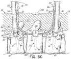
- FIGS. 6A-6Care schematic views sequentially illustrating yet another method of inserting a flexible spinal stabilization system into a patient
- FIGS. 7A-7Care schematic views sequentially illustrating yet another method of inserting a flexible spinal stabilization system into a patient.
- FIGS. 8A-8Dare schematic views sequentially illustrating yet another method of inserting a flexible spinal stabilization system into a patient.
- the stabilization system 10generally includes first and second vertebral anchors 14 , 16 secured to respective first and second vertebrae 18 , 20 in the patient's body 12 , a connecting element 22 configured to extend between the first and second anchors 14 , 16 , and a spacer, configured to be received over the connecting element 22 between the first and second vertebral anchors 18 , 20 .
- the connecting element 22may be, for example and without limitation, a flexible element such as a cord formed from polyethylene terephthalate (PET), titanium or metal materials, or other suitable materials recognized by those skilled in the art.
- PETpolyethylene terephthalate
- the surgeoncan be provided with several connecting elements 22 of varying elasticity to allow the surgeon to choose the connecting element based on the patient's condition.
- the spacer 24may be a flexible element formed, for example and without limitation, from polycarbonate-urethane (PCU), PEEK, polymeric and/or flexible materials, or other suitable materials recognized by those skilled in the art. In alternative embodiments, the spacer can be formed from a rigid material.
- the stabilization system 10includes elements of the Dynesys® system available from Zimmer Spine, Inc. of Edina, Minn. Those skilled in the art will appreciate, however, that the techniques and tools described below may also apply to other stabilization systems having similar components and/or operating upon similar principles.
- the stabilization systemcan be used in connection with other spinal implants, such as interbody fusion implants, biologic materials, artificial disks, nucleus repair materials, nucleus replacement implants, plates, screws, vertebral body replacement implants, interspinous process spacer implants, bone void filler materials and bone cement materials.
- spinal implantssuch as interbody fusion implants, biologic materials, artificial disks, nucleus repair materials, nucleus replacement implants, plates, screws, vertebral body replacement implants, interspinous process spacer implants, bone void filler materials and bone cement materials.
- the first and second vertebral anchors 14 , 16may be inserted into the patient's body 12 and secured using any technique known in the art.
- a first incision 30is made at a first location on the patient's skin 28 generally aligned above the first vertebra 18 .
- the first vertebral anchor 14is inserted through the first incision 30 and advanced through the patient's body 12 so that it may be secured to the first vertebra 18 .
- the second vertebral anchor 16may be inserted into the patient's body 12 in a similar manner. Specifically, a second incision 32 may be made at a second location on the patient's skin 28 generally aligned above the second vertebra 20 . The second vertebral anchor 16 is advanced into the patient's body 12 so that it may be secured to the second vertebra 20 .
- the first and second incisions 30 , 32may be sized so that minimally invasive, percutaneous techniques and/or retractor-based techniques may be used to advance and install the first and second vertebral anchors 14 , 16 in the patient's body 12 .
- the first and second incisions 30 , 32may alternatively be sized for traditional, open surgical procedures as well.
- the first and second vertebral anchors 14 , 16 shown in the drawingsare uniaxial pedicle screws each having a head 36 with first and second arms 38 , 40 ( FIG. 2 ) defining a receiving channel 42 and a shaft 44 extending from the head 36 .
- the shaft 44may include threads 46 ( FIG. 2 ) to facilitate securing the first and second vertebral anchors 14 , 16 to the respective first and second vertebrae 18 , 20 .
- the first and second vertebral anchors 14 , 16are merely exemplary in nature.
- Other types of vertebral anchorssuch as polyaxial pedicle screws, hooks, or other means for engaging the spine, may alternatively be used in the stabilization system 10 .
- FIGS. 1-3various components for inserting the stabilization system 10 into the patient's body 12 are shown.
- FIGS. 1 and 2show a first positioning tool 50 inserted through the first incision 30 and into the patient's body 12 along a path generally toward the first vertebral anchor 14 .
- the first positioning tool 50can be modified to provide for connection of the first positioning tool 50 to the vertebral anchor 14 outside the patient, the first positioning tool 50 and vertebral anchor 14 inserted through the incision 30 as a single unit.
- the first positioning tool 50can be used to guide the vertebral anchor 14 to the vertebral body 18 for securement to the vertebral body.
- a k-wire(not shown) that is secured to the vertebral body 18 can be used in connection with a cannulated vertebral anchor 14 to assist in proper securement and positioning of the vertebral anchor 14 .
- This method of securement of vertebral anchors to vertebral bodiesmay be used for any vertebral anchor used in the stabilization system 10 .
- the first positioning tool 50includes a first end 52 that may be coupled to the head 36 of the first vertebral anchor 14 using any suitable technique.
- the first positioning tool 50includes first and second bifurcations 54 , 56 defining an elongated slot or cavity 58 there between.
- the first and second bifurcations 54 , 56are each configured to be received over the respective first and second arms 38 , 40 on the head 36 of the first vertebral anchor 14 .
- the first and second bifurcations 54 , 56may also include one or more engagement features designed to mate with a corresponding engagement feature on the head 36 .
- first and second bifurcations 54 , 56may include a tab or projection 60 configured to be received in a slot 62 formed on an outer surface 64 of the head 36 .
- Other examples of possible arrangements for coupling the first end 52 of first positioning tool 50 to the first vertebral anchor 14are shown and described in U.S. patent application Ser. Nos. 11/737,151 and 11/743,481, the disclosures of which are fully incorporated herein by reference.
- the elongated slot 58may extend along the entire length of the first positioning tool 50 , which may include a handle (not shown) at a location outside the patient's body 12 .
- the elongated slot 58may only extend across a certain length of the first positioning tool 50 .
- the elongated slot 58need not extend all the way through the first positioning tool 50 .
- the first positioning tool 50may therefore have a substantially U-shaped cross section along its length rather than the first and second bifurcations 54 , 56 .
- FIG. 1shows the first vertebral anchor 14 substantially aligned along an axis 68 and the first positioning tool 50 coupled to the first vertebral anchor 14 along the axis 68
- the first positioning tool 50may alternatively be positioned and maintained at an angle relative to the axis 68 .
- FIG. 1shows the first positioning tool 50 positioned at an angle .theta. to the axis 68 .
- the angle .theta.is approximately 7.degree.
- the angle .theta.is approximately 14.degree.
- the first positioning tool 50may be coupled to the first vertebral anchor 14 in a manner that allows the angle .theta. to be adjusted as needed.
- FIG. 3shows a delivery device 70 positioned over the connecting element 22 .
- the delivery device 70may be made from any type of material suitable for insertion into a patient's body 12 .
- the delivery device 70is constructed from flexible polyethylene tubing having a rigidity greater than that of the connecting element 22 .
- the delivery device 70may be constructed from materials such as metal to provide even greater rigidity.
- the delivery device 70is shown as being a tubular element, other configurations are possible in which the delivery device 70 does not entirely surround the connecting element 22 .
- the delivery device 70may alternatively be a helical element (not shown) or some other structure extending over a length of the connecting element 22 to provide added rigidity for reasons discussed below.
- the delivery device 70may comprise multiple component parts assembled together from the same or a variety of different materials.
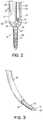
- the connecting element 22may be provided with an end portion 71 that is more rigid than the remainder of the connecting element 22 . This may be achieved by constructing the connecting element 22 with different material properties at the end portion 71 or by mounting a separate component to the connecting element 22 .
- the end portion 71may be a bullet-shaped nose or similar structure coupled to the connecting element 22 .
- the nosemay be constructed of metal or other rigid material and may be tapered to a tip 73 to facilitate movement through tissue.
- the material of the end portion 71may also be selected to help identify the location of the end portion 71 as the connecting element 22 is advanced through tissue.
- the end portion 71may be constructed from radiopaque material so as to serve as a marker during a surgical procedure.
- the connecting element 22may be positioned relative to the first and second vertebral anchors 14 , 16 using the first positioning tool 50 and delivery device 70 .
- the first positioning tool 50may be inserted through the first incision 30 and coupled to the head 36 of the first vertebral anchor 14 in the manner discussed above.
- the delivery device 70which is at least partially positioned over the connecting element 22 , may then be inserted through the first incision 30 and along at least a portion of the first positioning tool 50 .
- the delivery device 70may have a width smaller or larger than the width of the elongated slot 58 .
- the first positioning tool 50facilitates directing the delivery device 70 generally toward the second vertebral anchor 16 .
- FIG. 3Ashows the delivery device 70 having a diameter smaller than the width of the elongated slot 58 so that the delivery device 70 may be received within the elongated slot 58 .
- the elongated slot 58in such an embodiment may be provided with an engagement feature (not shown) configured to cooperate with a mating engagement feature (not shown) on the delivery device 70 .
- the engagement featuresmay be, for example, a tongue provided in the elongated slot 58 and a mating groove or track provided on the outer surface of the delivery device 70 .
- the delivery device 70may be provided with a tongue and the elongated slot 58 may be provided with a groove or track.
- Such engagement featureshelp guide the delivery device 70 along a desired path through elongated slot 58 so that the delivery device 70 is ultimately directed toward the second vertebral anchor 16 .
- FIG. 4shows one example of such an embodiment, with prime (′) marks being used to designate structure that slightly differs from FIG. 3A .
- a surgeonmay slide the delivery device 70 ′ along the first positioning tool 50 to facilitate directing the delivery device 70 ′ generally toward the second vertebral anchor 16 .
- the delivery device 70 ′may be formed with a desired degree of curvature.
- the surgeoncan guide the delivery device 70 ′ along a path corresponding to its curvature.
- the strength of the delivery device 70 and its ability to withstand compression forcesenables it to be advanced through tissue 72 in the patient's body 12 without being significantly deflected.
- a first portion 74 of the connecting element 22may remain exposed when the connecting element 22 is inserted with the delivery device 70 , but does not extend an appreciable distance so that the connecting element 22 does not adversely affect the insertion of the delivery device 70 through the tissue 72 .
- the end portion 71is in the form of a bullet-shaped nose (as shown), the shape and rigidity of the nose may facilitate movement of the connecting element 22 through the tissue 72 .
- the delivery device 70may be manipulated while being advanced along the first positioning tool 50 until the first portion 74 of the connecting element 22 is received in or near the receiving channel 42 of the second vertebral anchor 16 , as shown in FIG. 3B . To this end, the delivery device 70 may be passed through the first incision 30 and directed toward the second vertebral anchor 16 until it abuts and/or confronts a generally flat surface 76 defined by the head 36 . If the first portion 74 of the connecting element 22 remains exposed during this insertion, the first portion 74 may be received in the receiving channel 42 of the second vertebral anchor 16 without additional steps. If the delivery device 70 is positioned over the first portion 74 during insertion, the connecting element 22 may then be pushed through the delivery device 70 until the first portion 74 extends through the receiving channel 42 .
- the delivery device 70may be constructed from a flexible shape memory material, such as Nitinol.
- the shape memory materialmay be temperature-dependent such that the delivery device 70 has a normally straight configuration at room temperature, but assumes a curved configuration once placed within the patient's body 12 (where it is exposed to body temperatures).
- the delivery device 70may still be passed through the patient's body 12 and directed generally toward the second vertebral anchor 16 while using the first positioning tool 50 for guidance and/or leverage.
- the delivery device 70may not be directly aligned with the receiving channel 42 after directing the connecting element 22 toward the second vertebral anchor 16 . If necessary or desired, additional tools (not shown) may be inserted through the second incision 32 to help properly position the first portion 74 within the receiving channel 42 . Because the receiving channel 42 is open, the first portion 74 may be easily received by the second vertebral anchor 16 in a top-loading fashion. Radiographic images can be obtained to determine the proper positioning of the first portion 74 of the connecting element 22 .
- the end portion 71can be formed of a material that facilitates the identification of the proper placement of the connecting element 22 .
- a second positioning tool 80may be inserted through the second incision 32 and along a path generally toward the second vertebral anchor 16 .
- the second positioning tool 80includes a second end 82 configured to be coupled to the head 36 of the second vertebral anchor 16 in the same manner as the first end 52 of the first positioning tool 50 and the head 36 of the first vertebral anchor 14 .
- a fastener 84may then be passed through the second incision 32 and percutaneously delivered to the receiving channel 42 .
- the fastener 84may be delivered through an elongated slot 86 defined in the second positioning tool 80 , as shown in FIG. 3B .
- the fastener 84is secured within the receiving channel 42 so that the first portion 74 of the connecting element 22 is retained (e.g., compressed) between the fastener 84 and the second vertebral anchor 16 .
- the fastener 84is a set screw having external threads go that engage internal threads 92 ( FIG. 2 ) provided in the receiving channel 42 of the second vertebral anchor 16 .
- the fastener 84may be delivered through the second positioning tool 80 and tightened using a driving tool 94 , as shown in FIG. 3C (with the second positioning tool 80 shown in phantom for clarity).
- the second positioning tool 80stabilizes the second vertebral anchor 16 as the set screw is rotated to engage the internal threads 92 .
- the second positioning tool 80may serve as an anti-torque instrument to counteract the forces applied by the driving tool 94 .
- the first portion 74 of the connecting element 22may be secured to the head 36 of the second vertebral anchor 16 using different types of fasteners or other elements.
- the second vertebral anchor 16may alternatively be shaped to cooperate with a cap (not shown) for retaining the first portion 74 of the connecting element 22 .
- the second positioning tool 80may be removed from the patient's body 12 through the second incision 32 .
- the delivery device 70may also be removed from the connecting element 22 to expose a second portion 96 of the connecting element 22 . As shown in FIG. 3C , the delivery device 70 is removed through the first incision 30 in the patient's skin 28 .
- the tissue 72 surrounding the connecting element 22effectively maintains the connecting element 22 in position while the delivery device 70 is removed.
- FIG. 3Dillustrates the spacer 24 being advanced through the first incision 30 and over the connecting element 22 .
- the second positioning tool 80 and driving tool 94may be removed before or after the spacer 24 is advanced.
- the first positioning tool 50is shown as remaining within the patient's body 12 , it will be appreciated that the first positioning tool 50 may alternatively be removed through the first incision 30 prior to this step as well.
- the spacer 24may be advanced along the length of the connecting element 22 until a first end 98 of the spacer 24 confronts the generally flat surface 76 of the head 36 .
- a pushing instrument(not shown) may be used to aid in movement of the spacer 24 through tissue 72 and along the connecting element 22 .
- the pushing instrumentmay be inserted through the first incision 30 and adapted to engage a second end 100 of the spacer 24 to push the spacer 24 generally in the direction of arrow 102 .
- the pushing instrumentmay be adapted to engage a portion of the spacer 24 between the first and second ends 98 , 100 to adjust the orientation of the spacer 24 relative to the first vertebral anchor 14 and/or second vertebral anchor 16 .
- the pushing instrumentmay be inserted through a separate incision (not shown) or the second incision 32 .
- the surgeoncan determine the distance between vertebral anchors 14 , 16 and size the spacer 24 outside the patient to a length that achieves a desired patient outcome. For example, if the surgeon hopes to achieve posterior distraction between vertebrae, the spacer 24 can be sized greater than the distance between opposing surfaces of the vertebral anchors 14 , 16 upon which the spacer 24 engages. This measurement may be made, for example and without limitation, based on the distance outside the patient between instruments engaging the anchors or through radiographic means.
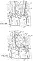
- the second portion 96 of the connecting element 22may extend generally toward the first incision 30 before being received in the receiving channel 42 of the first vertebral anchor 14 or the elongated slot 58 of the first positioning tool 50 .
- the second portion 96 of the connecting element 22may therefore be moved to a desired position relative to the first vertebral anchor 14 by manipulating the connecting element 22 by hand or by using one or more additional tools.
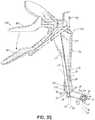
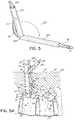
- a tensioning tool 150configured to cooperate with the first positioning tool 50 may be inserted through the first incision 30 .
- the tensioning tool 150includes a stabilizing element 152 having a top portion 154 aligned generally above the second end 100 of the spacer 24 .
- a bottom portion 156 of the tensioning tool 150may be inserted through the elongated slot 58 to an opposite side of the first positioning tool 50 to direct the second portion 96 of the connecting element 22 into the receiving channel 42 ( FIG. 2 ) of the first vertebral anchor 14 .
- the spacer 24is properly positioned between the first and second vertebral anchors 14 , 16 .
- Additional length 104 of the connecting element 22 extending from the second portion 96may curve upwardly and around the bottom portion 156 of the stabilizing element 152 so as to extend into the elongated slot 58 of the first positioning tool 50 . Indeed, the additional length may continue to extend out of the elongated slot 58 and through the top portion 154 of the stabilizing element 152 . While maintaining the bottom portion 156 of the stabilizing element 152 in position (so that the second portion 96 of the connecting element 22 is maintained in the receiving channel 42 ), the additional length 104 may be pulled to place the connecting element 22 in tension. The additional length 104 may be pulled manually by hand or by using a surgical tool.
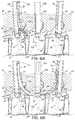
- the tensioning tool 150further includes a gripping element 158 having a first arm 160 configured to clamp or otherwise securely grip the connecting element 22 after the additional length 104 extends through the stabilizing element 152 .
- a surgeonmay pivot the first arm 160 relative to a second arm 162 of the gripping element 158 to mechanically pull the connecting element 22 through the stabilizing element 152 .
- the second portion 96is secured to the first vertebral anchor 14 .
- the second portion 96may be secured in a manner similar to the first portion 74 .
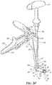
- a fastener 106such as a set screw, may be inserted through the first incision 30 and percutaneously delivered to the receiving channel 42 of the first vertebral anchor 14 . More specifically, the fastener 106 may be delivered through the stabilizing element 152 and first positioning tool 50 using a driving tool 170 , which may be similar to the driving tool 94 ( FIG. 3C ). A handle 172 of the driving tool 170 is rotated to drive the fastener 106 into engagement with the internal threads 92 ( FIG.
- the threaded engagementsecures the second portion 96 of the connecting element 22 relative to the first vertebral anchor 14 .
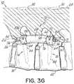
- the connecting element 22may then be cut proximate the first vertebral anchor 14 , and the first positioning tool 50 and the tensioning tool 150 may be removed from the patient's body 12 through the first incision 30 . This results in the arrangement shown in FIG. 3G .
- FIG. 5shows a delivery device 200 according to an alternative embodiment.
- the delivery device 200includes a first sheath member 202 coupled to a second sheath member 204 at an articulating joint 206 .
- the first sheath member 202is hollow so that it may be positioned over the connecting element 22 in the same manner as the delivery device 70 ( FIG. 3 ).
- the second sheath member 204may also be hollow, and may further include a slot 208 for accommodating the connecting element 22 .
- the second sheath member 204may be solid so that the connecting element 22 may only extend through the first sheath member 202 .
- the first sheath member 202may pivot relative to the second sheath member 204 to change the angle defined between the two components.
- the articulating joint 206may be configured to lock the first sheath member 202 at several different angles relative to the second sheath member 204 . Any suitable locking technique may be used.
- the articulating joint 206may include a ratcheting mechanism, locking pin, or other structure capable of locking the first sheath member 202 at one or more angles relative to the second sheath member 204 .
- the first sheath member 202may be designed to have an adjustable length.
- the first sheath member 202may include telescoping or extendable sections (not shown).
- FIGS. 5A-5Cillustrate the delivery device 200 being used to deliver the connecting element 22 to within the patient's body 12 , with like reference numbers being used to refer to like structure from FIGS. 3A-3G .
- the delivery device 200may be inserted through the first incision 30 within or near the first positioning tool 50 .
- the first sheath member 202 and/or second sheath member 204may be at least partially received in the elongated slot 58 of the first positioning tool 50 to help guide the first sheath member 202 generally toward the second vertebral anchor 16 .
- the delivery device 200may be used in a manner similar to the delivery device 70 ( FIG. 3A ) or the delivery device 70 ′ ( FIG. 4 ) depending on the diameters of the first sheath member 202 and second sheath member 204 .
- the delivery device 200is manipulated differently when passed through the first incision 30 . This difference is due to the first sheath member 202 being positioned at an angle relative to the second sheath member 204 (by means of the articulating joint 206 ). In some instances it may be easier to use the delivery device 200 to delivery the first portion 74 of the connecting element 22 to the second vertebral anchor 16 , whereas in other instances it may be easier to use the delivery device 70 . Note that the angle of the first sheath member 202 relative to the second sheath member 204 may be adjusted one or more times during the insertion of the delivery device 200 . Alternatively, the angle may be adjusted prior to insertion and maintained throughout the procedure.
- the first portion 74may be secured to the second vertebral anchor 16 in the same manner discussed above with reference to FIG. 3C .
- the delivery device 200may then be removed from the patient's body 12 by retracting it back through the first incision 30 and over the connecting element 22 .
- the angle of the first sheath member 202 relative to the second sheath member 204may be adjusted before or during this removal procedure.
- the spacer 24may be advanced over the connecting element 22 and the second portion 96 may be secured to the first vertebral anchor 14 , as discussed above with reference to FIGS. 3D-3G .
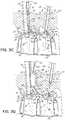
- FIGS. 6A-6Cillustrate a third vertebra 300 positioned between the first and second vertebrae 18 , 20 and a method of installing a stabilization system to effect treatment across the first, second, and third vertebrae 18 , 20 , 300 . Because the techniques and tools are similar to those discussed above with reference to FIGS. 3A-3G , like reference numbers are used to refer to like structure.
- a third vertebral anchor 302may be inserted through a third incision 304 at a third location on the patient's skin 28 and ultimately secured to the third vertebra 300 using conventional techniques.
- a third positioning tool 306may then be inserted through the third incision 304 and generally toward the third vertebral anchor 302 .
- the third vertebral anchor 302may be a pedicle screw having substantially the same construction as the first and second vertebral anchors 14 , 16 , and the third positioning tool 306 may have substantially the same construction as the first and second positioning tools 50 , 80 .
- the third positioning tool 306may include an elongated slot or cavity (not shown).
- a third end 310 of the third positioning tool 306may be coupled to the head 36 of the third vertebral anchor 302 using the techniques discussed above with reference to the first and second positioning tools 50 , 80 .
- the delivery device 70 and connecting element 22may be inserted through the first incision 30 .
- the first positioning tool 50is used to facilitate directing the delivery device 70 generally toward the third vertebral anchor 302 .
- the connecting element 22may be pushed through the delivery device 70 so that a third portion 312 (located between the first portion 74 and second portion 96 ) extends through the receiving channel 42 ( FIG.
- the connecting element 22may have a preformed curvature so that it curves upwardly and generally toward the second incision 32 when further pushed through the delivery device 70 .
- the first portion 74may be received in the elongated slot 86 and/or ultimately exit the patient's body 12 through the second incision 32 .
- the connecting element 22approaches the second vertebral anchor 16 when further pushed through the delivery device 70 .
- the first portion 74may then be received in the elongate slot 86 and pulled up through the second incision 32 .
- the third portion 312may be secured to the third vertebral anchor 302 using any suitable technique.
- the third portion 312may be retained in the receiving channel 42 ( FIG. 2 ) of the third vertebral anchor 302 by passing a fastener 314 , such as a set screw, through the elongated slot or cavity of the third positioning tool 306 and securing the fastener 314 within the receiving channel 42 over the third portion 312 .
- the delivery device 70may then be pulled back through the first incision 30 and removed from the connecting element 22 so as to expose the second portion 96 .
- the third portion 312is secured within the patient's body 12 whereas the first and second portions 74 , 96 are positioned in or proximate the elongated slots 58 , 86 , respectively.
- Such an arrangementallows spacers, like spacer 24 , to be placed over the connecting element 22 and for the first and second portions 74 , 96 to be secured to the first and second vertebral anchors 14 , 16 using the techniques described above.
- the tensioning tool 150FIGS. 3E and 3F
- fastener 106may be used to secure the second portion 96 to the first vertebral anchor 14
- the tensioning tool 150 and fastener 84may be used to secure the first portion 74 to the second vertebral anchor 16 .
- Any additional length of the connecting element 22 extending beyond the first and second portions 74 , 96may be cut proximate the first and second vertebral anchors 14 , 16 to complete the installation procedure.
- the surgeoncan be provided with several spacers each having different elastic characteristics for the multi-level construct shown in FIGS. 6A-6C .
- the surgeoncan choose the spacer, like spacer 24 , based on the patient's condition and include spacers having different elastic characteristics in a single patient, if desired.
- the spacer between anchors 14 and 302can be a more elastic material and the spacer between anchors 302 and 16 can be a more rigid material.
- the surgeoncan be provided a single connecting element that has varying elastic characteristics over its length for the multi-level construct shown in FIGS. 6A-6C .
- the surgeonmay then implant the elastically varied connecting element in a desired location to provide a desired result in the patient.
- the elastically varied connecting elementcan include radiographic markers that assist the surgeon in identifying the differing areas of elasticity when the connecting element is implanted in the patient to provide differing characteristics of the stabilization system 10 at adjacent levels.
- FIGS. 7A-7Cillustrate another method of installing the stabilization system 10 for the purpose of multi-level treatment. Because the method uses many of the same components as the method shown in FIGS. 6A-6C , like reference numbers are used to refer to like structure. Additionally, only the differences between the methods are described below.
- a delivery device 400is positioned over the connecting element 22 .
- the delivery device 400comprises a first sheath member 402 and a second sheath member 404 , which may or may not have substantially the same shape and/or length.
- the delivery device 400 and connecting element 22are inserted through the first incision 30 and along at least a portion of the first positioning tool 50 before the third end 310 of the third positioning tool 306 is coupled to the head 36 of the third vertebral anchor 302 .
- FIG. 7Ashows the first sheath member 402 spaced apart from the second sheath member 404 such that the third portion 312 of the connecting element 22 is exposed within the patient's body 12 , the second sheath member 404 may alternatively be advanced over the third portion 312 during this insertion so as to abut the first sheath member 402 .
- the first sheath member 402is directed past the third vertebral anchor 302 so that the third portion 312 of the connecting element 22 is positioned proximate the head 36 of the third vertebral anchor 302 .
- the second sheath member 404abuts the first sheath member 402
- the second sheath member 404is retracted to expose the third portion 312 .
- the third positioning tool 306may then be directed downwardly to the third vertebral anchor 302 so that the third portion 312 is received in the elongated slot or cavity of the third positioning tool 306 .
- the third portion 312may be secured to the third vertebral anchor 302 using the fastener 314 or any other suitable technique.
- the first sheath member 402has a preformed curvature so that it curves slightly upwardly toward the patient's skin 28 after being advanced past the third vertebral anchor 302 .
- the first sheath member 402may eventually contact the second positioning tool 80 , which may be used to facilitate directing the first sheath member 402 to the second incision 32 .
- the first sheath member 402may be at least partially received in the elongated slot 86 and may slide along the elongated slot 86 when further advanced past the third vertebral anchor 302 .
- the first and second sheath members 402 , 404may be removed from the patient's body 12 and connecting element 22 . More specifically, the first sheath member 402 may be removed through the second incision 32 and from the connecting element 22 so as the leave the first portion 74 positioned in or proximate the elongated slot 86 . The second sheath member 404 may be removed back through the first incision 30 and off the connecting element 22 so as to leave the second portion 96 positioned in or proximate the elongated slot 58 .
- first portion 74may be secured to the second vertebral anchor 16 and the second portion 96 may be secured to the first vertebral anchor 14 using any of the techniques discussed above. It will be appreciated that the third positioning tool 306 may be removed through the third incision 304 before or after removing the first and second sheath members 402 , 404 and/or securing the first and second portions 74 , 96 .
- FIGS. 8A-8Dillustrate yet another method of installing the stabilization system 10 for the purpose of multi-level treatment.
- Like reference numbersare once again used to refer to like structure from the other embodiments discussed above.
- the first, second, and third positioning tools 50 , 80 , 306are inserted through the respective first, second, and third incisions 30 , 32 , 304 and coupled to the respective first, second, and third vertebral anchors 14 , 16 , 302 .
- the connecting element 22is inserted through the elongated slot in the third positioning tool 306 so that the first portion 74 extends generally toward the first positioning tool 50 and the second portion 96 extends generally toward the second positioning tool 80 .
- a first delivery device 500may then be positioned over the first portion 74 and a second delivery device 502 may be positioned over the second portion 96 .
- the first and second delivery devices 500 , 502may be used to direct the first and second portions 74 , 96 through the patient's body 12 .
- the first delivery device 500 and the first portion 74 of the connecting element 22may be inserted through the third incision 304 and along at least a portion of the third positioning tool 306 .
- the third positioning tool 306may be used for guidance and/or leverage to help direct the first delivery device 500 and first portion 74 along a path through the patient's body 12 and generally toward the first vertebral anchor 14 .
- the third positioning tool 306 and its elongated slotmay be used in a way similar to which the first positioning tool 50 and elongated slot 58 are used in the other embodiments discussed above.
- the first delivery device 500 contacts the first vertebral anchor 14 and/or first positioning tool 50it may be directed upwardly toward the first incision 30 .
- the first delivery device 500may slide along the elongated slot 58 and exit the patient's body 12 through the first incision 30 when sufficiently advanced through the third incision 304 .
- the tissue 72 within the patient's body 12helps maintain the first delivery device 500 and connecting element 22 within the patient's body 12 between the first and third incisions 30 , 304 .
- the second delivery device 502 and second portion 96 of the connecting element 22may be inserted into the patient's body 12 in a similar manner. Specifically, the second delivery device 502 and second portion 96 may be inserted through the third incision 304 and generally toward the second vertebral anchor 16 , using the third positioning tool 306 for guidance and/or leverage when needed. When the second delivery device 502 contacts the second vertebral anchor 16 and/or second positioning tool 80 , it may be directed upwardly toward the second incision 32 . For example, the second delivery device 502 may slide along the elongated slot 86 toward the second incision 32 .
- the third portion 312 of the connecting element 22may be pushed downwardly through the third positioning tool 306 and into the receiving channel 42 ( FIG. 2 ) in the head 36 of the third vertebral anchor 302 .
- Any suitable toolmay be used to push the third portion 312 , including the fastener 314 and driving tool 94 ultimately used to retain the third portion 312 within the receiving channel 42 .
- the first and second delivery devices 500 , 502are further advanced into the patient's body 12 as well.
- the first delivery device 500eventually extends from the third vertebral anchor 302 to the first incision 30 and the second delivery device 502 eventually extends from the third vertebral anchor 302 to the second incision 32 .
- the first and second delivery devices 500 , 502may be removed from the patient's body 12 through the respective first and second incisions 30 , 32 . Removing the first and second delivery devices 500 , 502 exposes the first and second portions 74 , 96 , which may be secured to the respective first and second vertebral anchors 14 , 16 using any of the techniques discussed above.
Landscapes
- Health & Medical Sciences (AREA)
- Orthopedic Medicine & Surgery (AREA)
- Life Sciences & Earth Sciences (AREA)
- Surgery (AREA)
- Neurology (AREA)
- Heart & Thoracic Surgery (AREA)
- Engineering & Computer Science (AREA)
- Biomedical Technology (AREA)
- Nuclear Medicine, Radiotherapy & Molecular Imaging (AREA)
- Medical Informatics (AREA)
- Molecular Biology (AREA)
- Animal Behavior & Ethology (AREA)
- General Health & Medical Sciences (AREA)
- Public Health (AREA)
- Veterinary Medicine (AREA)
- Surgical Instruments (AREA)
- Prostheses (AREA)
Abstract
Description
Claims (20)
Priority Applications (1)
| Application Number | Priority Date | Filing Date | Title |
|---|---|---|---|
| US16/788,991US10856910B2 (en) | 2008-02-05 | 2020-02-12 | System and method for insertion of flexible spinal stabilization element |
Applications Claiming Priority (4)
| Application Number | Priority Date | Filing Date | Title |
|---|---|---|---|
| US12/025,984US9277940B2 (en) | 2008-02-05 | 2008-02-05 | System and method for insertion of flexible spinal stabilization element |
| US14/800,309US9782203B2 (en) | 2008-02-05 | 2015-07-15 | System and method for insertion of flexible spinal stabilization element |
| US15/718,052US10603079B2 (en) | 2008-02-05 | 2017-09-28 | System and method for insertion of flexible spinal stabilization element |
| US16/788,991US10856910B2 (en) | 2008-02-05 | 2020-02-12 | System and method for insertion of flexible spinal stabilization element |
Related Parent Applications (1)
| Application Number | Title | Priority Date | Filing Date |
|---|---|---|---|
| US15/718,052ContinuationUS10603079B2 (en) | 2008-02-05 | 2017-09-28 | System and method for insertion of flexible spinal stabilization element |
Publications (2)
| Publication Number | Publication Date |
|---|---|
| US20200179012A1 US20200179012A1 (en) | 2020-06-11 |
| US10856910B2true US10856910B2 (en) | 2020-12-08 |
Family
ID=40932426
Family Applications (4)
| Application Number | Title | Priority Date | Filing Date |
|---|---|---|---|
| US12/025,984Active2033-08-31US9277940B2 (en) | 2008-02-05 | 2008-02-05 | System and method for insertion of flexible spinal stabilization element |
| US14/800,309Active2028-02-23US9782203B2 (en) | 2008-02-05 | 2015-07-15 | System and method for insertion of flexible spinal stabilization element |
| US15/718,052ActiveUS10603079B2 (en) | 2008-02-05 | 2017-09-28 | System and method for insertion of flexible spinal stabilization element |
| US16/788,991ActiveUS10856910B2 (en) | 2008-02-05 | 2020-02-12 | System and method for insertion of flexible spinal stabilization element |
Family Applications Before (3)
| Application Number | Title | Priority Date | Filing Date |
|---|---|---|---|
| US12/025,984Active2033-08-31US9277940B2 (en) | 2008-02-05 | 2008-02-05 | System and method for insertion of flexible spinal stabilization element |
| US14/800,309Active2028-02-23US9782203B2 (en) | 2008-02-05 | 2015-07-15 | System and method for insertion of flexible spinal stabilization element |
| US15/718,052ActiveUS10603079B2 (en) | 2008-02-05 | 2017-09-28 | System and method for insertion of flexible spinal stabilization element |
Country Status (6)
| Country | Link |
|---|---|
| US (4) | US9277940B2 (en) |
| EP (1) | EP2254494B1 (en) |
| CN (1) | CN102014776A (en) |
| AU (1) | AU2008349784A1 (en) |
| CA (1) | CA2715243A1 (en) |
| WO (1) | WO2009099477A2 (en) |
Cited By (3)
| Publication number | Priority date | Publication date | Assignee | Title |
|---|---|---|---|---|
| US20210121208A1 (en)* | 2017-08-29 | 2021-04-29 | Zimmer Biomet Spine, Inc. | Surgical cord tensioning devices, systems, and methods |
| US12102348B2 (en) | 2016-09-07 | 2024-10-01 | Vertos Medical, Inc. | Percutaneous lateral recess resection methods and instruments |
| US12324572B2 (en) | 2022-06-16 | 2025-06-10 | Vertos Medical, Inc. | Integrated instrument assembly |
Families Citing this family (74)
| Publication number | Priority date | Publication date | Assignee | Title |
|---|---|---|---|---|
| US7833250B2 (en) | 2004-11-10 | 2010-11-16 | Jackson Roger P | Polyaxial bone screw with helically wound capture connection |
| US7862587B2 (en) | 2004-02-27 | 2011-01-04 | Jackson Roger P | Dynamic stabilization assemblies, tool set and method |
| US10729469B2 (en) | 2006-01-09 | 2020-08-04 | Roger P. Jackson | Flexible spinal stabilization assembly with spacer having off-axis core member |
| US10258382B2 (en) | 2007-01-18 | 2019-04-16 | Roger P. Jackson | Rod-cord dynamic connection assemblies with slidable bone anchor attachment members along the cord |
| US8353932B2 (en) | 2005-09-30 | 2013-01-15 | Jackson Roger P | Polyaxial bone anchor assembly with one-piece closure, pressure insert and plastic elongate member |
| US8292926B2 (en) | 2005-09-30 | 2012-10-23 | Jackson Roger P | Dynamic stabilization connecting member with elastic core and outer sleeve |
| US8876868B2 (en) | 2002-09-06 | 2014-11-04 | Roger P. Jackson | Helical guide and advancement flange with radially loaded lip |
| US7621918B2 (en) | 2004-11-23 | 2009-11-24 | Jackson Roger P | Spinal fixation tool set and method |
| US7377923B2 (en) | 2003-05-22 | 2008-05-27 | Alphatec Spine, Inc. | Variable angle spinal screw assembly |
| US7776067B2 (en) | 2005-05-27 | 2010-08-17 | Jackson Roger P | Polyaxial bone screw with shank articulation pressure insert and method |
| US8092500B2 (en) | 2007-05-01 | 2012-01-10 | Jackson Roger P | Dynamic stabilization connecting member with floating core, compression spacer and over-mold |
| US7766915B2 (en) | 2004-02-27 | 2010-08-03 | Jackson Roger P | Dynamic fixation assemblies with inner core and outer coil-like member |
| US8366753B2 (en) | 2003-06-18 | 2013-02-05 | Jackson Roger P | Polyaxial bone screw assembly with fixed retaining structure |
| US8926670B2 (en) | 2003-06-18 | 2015-01-06 | Roger P. Jackson | Polyaxial bone screw assembly |
| US7967850B2 (en) | 2003-06-18 | 2011-06-28 | Jackson Roger P | Polyaxial bone anchor with helical capture connection, insert and dual locking assembly |
| US7955355B2 (en) | 2003-09-24 | 2011-06-07 | Stryker Spine | Methods and devices for improving percutaneous access in minimally invasive surgeries |
| US7179261B2 (en) | 2003-12-16 | 2007-02-20 | Depuy Spine, Inc. | Percutaneous access devices and bone anchor assemblies |
| US7527638B2 (en) | 2003-12-16 | 2009-05-05 | Depuy Spine, Inc. | Methods and devices for minimally invasive spinal fixation element placement |
| US11419642B2 (en) | 2003-12-16 | 2022-08-23 | Medos International Sarl | Percutaneous access devices and bone anchor assemblies |
| JP2007525274A (en) | 2004-02-27 | 2007-09-06 | ロジャー・ピー・ジャクソン | Orthopedic implant rod reduction instrument set and method |
| US7160300B2 (en) | 2004-02-27 | 2007-01-09 | Jackson Roger P | Orthopedic implant rod reduction tool set and method |
| US11241261B2 (en) | 2005-09-30 | 2022-02-08 | Roger P Jackson | Apparatus and method for soft spinal stabilization using a tensionable cord and releasable end structure |
| US8152810B2 (en)* | 2004-11-23 | 2012-04-10 | Jackson Roger P | Spinal fixation tool set and method |
| US7651502B2 (en) | 2004-09-24 | 2010-01-26 | Jackson Roger P | Spinal fixation tool set and method for rod reduction and fastener insertion |
| US8926672B2 (en) | 2004-11-10 | 2015-01-06 | Roger P. Jackson | Splay control closure for open bone anchor |
| US8444681B2 (en) | 2009-06-15 | 2013-05-21 | Roger P. Jackson | Polyaxial bone anchor with pop-on shank, friction fit retainer and winged insert |
| US9168069B2 (en) | 2009-06-15 | 2015-10-27 | Roger P. Jackson | Polyaxial bone anchor with pop-on shank and winged insert with lower skirt for engaging a friction fit retainer |
| WO2006057837A1 (en) | 2004-11-23 | 2006-06-01 | Jackson Roger P | Spinal fixation tool attachment structure |
| US9216041B2 (en) | 2009-06-15 | 2015-12-22 | Roger P. Jackson | Spinal connecting members with tensioned cords and rigid sleeves for engaging compression inserts |
| US7901437B2 (en) | 2007-01-26 | 2011-03-08 | Jackson Roger P | Dynamic stabilization member with molded connection |
| WO2007038429A1 (en) | 2005-09-27 | 2007-04-05 | Endius, Inc. | Methods and apparatuses for stabilizing the spine through an access device |
| US8105368B2 (en) | 2005-09-30 | 2012-01-31 | Jackson Roger P | Dynamic stabilization connecting member with slitted core and outer sleeve |
| CA2670988C (en) | 2006-12-08 | 2014-03-25 | Roger P. Jackson | Tool system for dynamic spinal implants |
| US8475498B2 (en) | 2007-01-18 | 2013-07-02 | Roger P. Jackson | Dynamic stabilization connecting member with cord connection |
| US8366745B2 (en) | 2007-05-01 | 2013-02-05 | Jackson Roger P | Dynamic stabilization assembly having pre-compressed spacers with differential displacements |
| US8979904B2 (en) | 2007-05-01 | 2015-03-17 | Roger P Jackson | Connecting member with tensioned cord, low profile rigid sleeve and spacer with torsion control |
| US10383660B2 (en) | 2007-05-01 | 2019-08-20 | Roger P. Jackson | Soft stabilization assemblies with pretensioned cords |
| US9277940B2 (en) | 2008-02-05 | 2016-03-08 | Zimmer Spine, Inc. | System and method for insertion of flexible spinal stabilization element |
| AU2010260521C1 (en) | 2008-08-01 | 2013-08-01 | Roger P. Jackson | Longitudinal connecting member with sleeved tensioned cords |
| US8137355B2 (en) | 2008-12-12 | 2012-03-20 | Zimmer Spine, Inc. | Spinal stabilization installation instrumentation and methods |
| US8998959B2 (en) | 2009-06-15 | 2015-04-07 | Roger P Jackson | Polyaxial bone anchors with pop-on shank, fully constrained friction fit retainer and lock and release insert |
| US11229457B2 (en) | 2009-06-15 | 2022-01-25 | Roger P. Jackson | Pivotal bone anchor assembly with insert tool deployment |
| CN103826560A (en) | 2009-06-15 | 2014-05-28 | 罗杰.P.杰克逊 | Polyaxial Bone Anchor with Socket Stem and Winged Inserts with Friction Fit Compression Collars |
| US9668771B2 (en) | 2009-06-15 | 2017-06-06 | Roger P Jackson | Soft stabilization assemblies with off-set connector |
| US20110009906A1 (en)* | 2009-07-13 | 2011-01-13 | Zimmer Spine, Inc. | Vertebral stabilization transition connector |
| US9211144B2 (en)* | 2009-09-09 | 2015-12-15 | Globus Medical, Inc. | Spine surgery device and method |
| EP2485654B1 (en) | 2009-10-05 | 2021-05-05 | Jackson P. Roger | Polyaxial bone anchor with non-pivotable retainer and pop-on shank, some with friction fit |
| US8328849B2 (en)* | 2009-12-01 | 2012-12-11 | Zimmer Gmbh | Cord for vertebral stabilization system |
| US8740945B2 (en) | 2010-04-07 | 2014-06-03 | Zimmer Spine, Inc. | Dynamic stabilization system using polyaxial screws |
| US8382803B2 (en) | 2010-08-30 | 2013-02-26 | Zimmer Gmbh | Vertebral stabilization transition connector |
| AU2011299558A1 (en) | 2010-09-08 | 2013-05-02 | Roger P. Jackson | Dynamic stabilization members with elastic and inelastic sections |
| US8968319B2 (en) | 2011-06-20 | 2015-03-03 | Spinefrontier, Inc | Methods, tools and devices for spinal fixation |
| US8911479B2 (en) | 2012-01-10 | 2014-12-16 | Roger P. Jackson | Multi-start closures for open implants |
| US8911478B2 (en) | 2012-11-21 | 2014-12-16 | Roger P. Jackson | Splay control closure for open bone anchor |
| US10058354B2 (en) | 2013-01-28 | 2018-08-28 | Roger P. Jackson | Pivotal bone anchor assembly with frictional shank head seating surfaces |
| US8852239B2 (en) | 2013-02-15 | 2014-10-07 | Roger P Jackson | Sagittal angle screw with integral shank and receiver |
| US9554835B2 (en) | 2013-03-14 | 2017-01-31 | Warsaw Orthopedic, Inc. | Surgical implant system and method |
| US9387018B2 (en) | 2013-03-14 | 2016-07-12 | Warsaw Orthopedic, Inc. | Surgical implant system and method |
| EP2967653B1 (en)* | 2013-03-15 | 2019-05-29 | Shriners Hospitals for Children | Techniques for spinal surgery |
| US9566092B2 (en) | 2013-10-29 | 2017-02-14 | Roger P. Jackson | Cervical bone anchor with collet retainer and outer locking sleeve |
| US9717533B2 (en) | 2013-12-12 | 2017-08-01 | Roger P. Jackson | Bone anchor closure pivot-splay control flange form guide and advancement structure |
| US9451993B2 (en) | 2014-01-09 | 2016-09-27 | Roger P. Jackson | Bi-radial pop-on cervical bone anchor |
| US9597119B2 (en) | 2014-06-04 | 2017-03-21 | Roger P. Jackson | Polyaxial bone anchor with polymer sleeve |
| US10064658B2 (en) | 2014-06-04 | 2018-09-04 | Roger P. Jackson | Polyaxial bone anchor with insert guides |
| US9724131B2 (en) | 2014-09-25 | 2017-08-08 | DePuy Synthes Products, Inc. | Spinal connectors and related methods |
| CA3008161C (en) | 2014-12-09 | 2023-09-26 | John A. Heflin | Spine alignment system |
| US9924983B2 (en)* | 2015-02-11 | 2018-03-27 | Warsaw Orthopedic, Inc. | Spinal correction method and system |
| CN106361413A (en)* | 2015-07-24 | 2017-02-01 | 镱钛科技股份有限公司 | Puncture guide |
| US10456174B2 (en) | 2017-07-31 | 2019-10-29 | Medos International Sarl | Connectors for use in systems and methods for reducing the risk of proximal junctional kyphosis |
| US10463403B2 (en)* | 2017-07-31 | 2019-11-05 | Medos International Sarl | Systems and methods for reducing the risk of proximal junctional kyphosis using a bone anchor or other attachment point |
| US10939941B2 (en)* | 2017-08-29 | 2021-03-09 | Zimmer Biomet Spine, Inc. | Surgical cord tensioning devices, systems, and methods |
| US11020149B2 (en)* | 2018-02-28 | 2021-06-01 | Globus Medical Inc. | Scoliosis correction systems, methods, and instruments |
| AU2019358075B2 (en)* | 2018-10-10 | 2022-03-17 | Zimmer Biomet Spine, Inc. | Surgical cord tensioning devices and systems |
| US11389204B2 (en) | 2020-12-17 | 2022-07-19 | Institute For Spine & Scoliosis, P.A. | Method for improved spinal correction surgery implementing non-fusion anterior scoliosis correction techniques for release of discs |
Citations (62)
| Publication number | Priority date | Publication date | Assignee | Title |
|---|---|---|---|---|
| US5318566A (en) | 1992-06-22 | 1994-06-07 | Danek Medical, Inc. | Sternotomy cable and method |
| US5562660A (en) | 1993-02-09 | 1996-10-08 | Plus Endoprothetik Ag | Apparatus for stiffening and/or correcting the vertebral column |
| US6290700B1 (en) | 1997-07-31 | 2001-09-18 | Plus Endoprothetik Ag | Device for stiffening and/or correcting a vertebral column or such like |
| US20020035366A1 (en) | 2000-09-18 | 2002-03-21 | Reto Walder | Pedicle screw for intervertebral support elements |
| US20030060826A1 (en) | 1999-10-20 | 2003-03-27 | Foley Kevin T. | Instruments and methods for stabilization of bony structures |
| US20030083657A1 (en)* | 2001-10-30 | 2003-05-01 | Drewry Troy D. | Flexible spinal stabilization system and method |
| US6616667B1 (en) | 1999-11-25 | 2003-09-09 | Sulzer Orthopedics, Ltd. | Surgical instrument for tensioning a cable-like tensioning element |
| US6648888B1 (en) | 2002-09-06 | 2003-11-18 | Endius Incorporated | Surgical instrument for moving a vertebra |
| US20040087950A1 (en) | 2000-06-23 | 2004-05-06 | Teitelbaum George P. | Percutaneous vertebral fusion system |
| US20040143264A1 (en) | 2002-08-23 | 2004-07-22 | Mcafee Paul C. | Metal-backed UHMWPE rod sleeve system preserving spinal motion |
| US20050010220A1 (en) | 2003-04-24 | 2005-01-13 | Simon Casutt | Instrument system for pedicle screws |
| US20050131407A1 (en) | 2003-12-16 | 2005-06-16 | Sicvol Christopher W. | Flexible spinal fixation elements |
| US20050192589A1 (en) | 2004-02-06 | 2005-09-01 | Douglas Raymond | Devices and methods for inserting a spinal fixation element |
| US20050277922A1 (en) | 2004-06-09 | 2005-12-15 | Trieu Hai H | Systems and methods for flexible spinal stabilization |
| US20060036255A1 (en) | 2004-08-13 | 2006-02-16 | Pond John D Jr | System and method for positioning a connecting member adjacent the spinal column in minimally invasive procedures |
| US20060074418A1 (en) | 2004-09-24 | 2006-04-06 | Jackson Roger P | Spinal fixation tool set and method for rod reduction and fastener insertion |
| US20060111715A1 (en) | 2004-02-27 | 2006-05-25 | Jackson Roger P | Dynamic stabilization assemblies, tool set and method |
| US20060149242A1 (en) | 2004-12-17 | 2006-07-06 | Gary Kraus | Spinal stabilization systems supplemented with diagnostically opaque materials |
| US20060149238A1 (en) | 2005-01-04 | 2006-07-06 | Sherman Michael C | Systems and methods for spinal stabilization with flexible elements |
| US7094240B2 (en) | 2003-01-10 | 2006-08-22 | Sdgi Holdings, Inc. | Flexible member tensioning instruments and methods |
| US20060195090A1 (en) | 2005-02-10 | 2006-08-31 | Loubert Suddaby | Apparatus for and method of aligning a spine |
| US20060247630A1 (en) | 2005-04-27 | 2006-11-02 | Andrew Iott | Percutaneous vertebral stabilization system |
| US20070005063A1 (en) | 2005-06-20 | 2007-01-04 | Sdgi Holdings, Inc. | Multi-level multi-functional spinal stabilization systems and methods |
| US20070042633A1 (en) | 2004-03-04 | 2007-02-22 | Robert Frigg | Connecting element |
| US20070078460A1 (en) | 2005-08-25 | 2007-04-05 | Robert Frigg | Methods of spinal fixation and instrumentation |
| US20070083210A1 (en) | 2005-09-16 | 2007-04-12 | Zimmer Spine, Inc. | Apparatus and method for minimally invasive spine surgery |
| US20070118119A1 (en) | 2005-11-18 | 2007-05-24 | Zimmer Spine, Inc. | Methods and device for dynamic stabilization |
| US20070191836A1 (en) | 2006-01-27 | 2007-08-16 | Sdgi Holdings, Inc. | Methods and devices for a minimally invasive placement of a rod within a patient |
| US7275336B2 (en) | 2003-04-24 | 2007-10-02 | Zimmer Gmbh | Distance measuring instrument for pedicle screws |
| US20070233075A1 (en) | 2006-03-16 | 2007-10-04 | Zimmer Spine, Inc. | Spinal fixation device with variable stiffness |
| US20070270860A1 (en) | 2005-09-30 | 2007-11-22 | Jackson Roger P | Dynamic stabilization connecting member with slitted core and outer sleeve |
| US20070288011A1 (en) | 2006-04-18 | 2007-12-13 | Joseph Nicholas Logan | Spinal Rod System |
| US20070299443A1 (en) | 2006-06-09 | 2007-12-27 | Endius, Inc. | Methods and apparatus for access to and/or treatment of the spine |
| US20080009863A1 (en) | 2006-06-23 | 2008-01-10 | Zimmer Spine, Inc. | Pedicle screw distractor and associated method of use |
| US20080021459A1 (en) | 2006-07-07 | 2008-01-24 | Warsaw Orthopedic Inc. | Dynamic constructs for spinal stabilization |
| US20080051787A1 (en) | 2006-08-22 | 2008-02-28 | Neuropro Technologies, Inc. | Percutaneous system for dynamic spinal stabilization |
| US20080140133A1 (en) | 2006-12-08 | 2008-06-12 | Randall Noel Allard | Methods and Devices for Treating a Multi-Level Spinal Deformity |
| US20080177317A1 (en) | 2007-01-18 | 2008-07-24 | Jackson Roger P | Dynamic stabilization connecting member with cord connection |
| US20080234738A1 (en) | 2007-03-23 | 2008-09-25 | Zimmer Gmbh | System and method for insertion of flexible spinal stabilization element |
| US20080249531A1 (en) | 2007-02-27 | 2008-10-09 | Warsaw Orthopedic, Inc. | Instruments and methods for minimally invasive insertion of dynamic implants |
| US20080275456A1 (en) | 2007-05-02 | 2008-11-06 | Zimmer Spine, Inc. | Installation systems for spinal stabilization system and related methods |
| US20080294198A1 (en) | 2006-01-09 | 2008-11-27 | Jackson Roger P | Dynamic spinal stabilization assembly with torsion and shear control |
| US20080312704A1 (en) | 2007-06-12 | 2008-12-18 | Zimmer Spine, Inc. | Instrumentation and associated techniques for minimally invasive spinal construct installation |
| US20090054902A1 (en)* | 2007-08-21 | 2009-02-26 | Depuy Spine, Inc. | Tether tensioning instrument |
| US20090054933A1 (en)* | 2007-08-21 | 2009-02-26 | Depuy Spine, Inc. | Instruments and methods for tensioning a spinal tether |
| US20090088799A1 (en) | 2007-10-01 | 2009-04-02 | Chung-Chun Yeh | Spinal fixation device having a flexible cable and jointed components received thereon |
| US20090198281A1 (en) | 2008-02-05 | 2009-08-06 | Zimmer Spine, Inc. | System and method for insertion of flexible spinal stabilization element |
| US20090204118A1 (en) | 2008-02-13 | 2009-08-13 | William Ralph Pratt | Surgical cable with malleable leader segment |
| US7708763B2 (en) | 2003-12-16 | 2010-05-04 | Depuy Spine, Inc. | Methods and devices for minimally invasive spinal fixation element placement |
| US7922725B2 (en) | 2007-04-19 | 2011-04-12 | Zimmer Spine, Inc. | Method and associated instrumentation for installation of spinal dynamic stabilization system |
| US8043343B2 (en) | 2007-06-28 | 2011-10-25 | Zimmer Spine, Inc. | Stabilization system and method |
| US8216245B2 (en) | 2009-10-30 | 2012-07-10 | Warsaw Orthopedic | Apparatus and method for applying sustained tension on a tether |
| US8226656B2 (en) | 2008-04-16 | 2012-07-24 | Warsaw Orthopedic, Inc. | Minimally invasive systems and methods for insertion of a connecting member adjacent the spinal column |
| US8267968B2 (en) | 2009-06-24 | 2012-09-18 | Neuropro Technologies, Inc. | Percutaneous system for dynamic spinal stabilization |
| US8328849B2 (en) | 2009-12-01 | 2012-12-11 | Zimmer Gmbh | Cord for vertebral stabilization system |
| US8465495B2 (en) | 2008-11-07 | 2013-06-18 | Zimmer Spine | Surgical tool for tensioning a flexible member |
| US8540720B2 (en) | 2007-12-06 | 2013-09-24 | Javier Garcia-Bengochea | System, instrumentation and method for spinal fixation using minimally invasive surgical techniques |
| US20140257416A1 (en)* | 2013-03-06 | 2014-09-11 | Nathan Meyer | Percutaneous rod inserter |
| US9339309B1 (en) | 2012-10-11 | 2016-05-17 | Nuvasive, Inc. | Systems and methods for inserting cross-connectors |
| US9339303B2 (en) | 2008-12-17 | 2016-05-17 | Lanx, S.R.L. | Modular vertebral stabilizer |
| US9757167B2 (en) | 2015-03-11 | 2017-09-12 | K2M, Inc. | Inserter and method for securing an implant to a spinal process with a flexible fastening system |
| US10022172B2 (en) | 2014-06-25 | 2018-07-17 | Spine Wave, Inc. | Minimally invasive posterolateral fusion |
Family Cites Families (111)
| Publication number | Priority date | Publication date | Assignee | Title |
|---|---|---|---|---|
| US2248054A (en) | 1939-06-07 | 1941-07-08 | Becker Joseph | Screw driver |
| NL7610576A (en) | 1976-09-23 | 1978-03-29 | Gerard Hendrik Slot | Spinal column repositioning system - uses tongs to position screws in column sections before securing to rope |
| FR2521478A1 (en) | 1982-02-17 | 1983-08-19 | Aerospatiale | AUTOMATIC INSTALLATION DEVICE FOR ASSEMBLY SYSTEMS |
| DE3614101C1 (en) | 1986-04-25 | 1987-10-22 | Juergen Prof Dr Med Harms | Pedicle screw |
| ZA871322B (en) | 1987-02-24 | 1987-10-28 | Alexander Else Frederick | Screw holder |
| DE3800052A1 (en) | 1987-07-08 | 1989-07-13 | Harms Juergen | POSITIONING SCREW |
| DE3823737A1 (en) | 1988-07-13 | 1990-01-18 | Lutz Biedermann | CORRECTION AND HOLDING DEVICE, ESPECIALLY FOR THE SPINE |
| US5261913A (en) | 1989-07-26 | 1993-11-16 | J.B.S. Limited Company | Device for straightening, securing, compressing and elongating the spinal column |
| DE3936702C2 (en) | 1989-11-03 | 1994-07-28 | Lutz Biedermann | Pedicle screw and correction and holding device with such a pedicle screw |
| US5030220A (en) | 1990-03-29 | 1991-07-09 | Advanced Spine Fixation Systems Incorporated | Spine fixation system |
| WO1991016020A1 (en) | 1990-04-26 | 1991-10-31 | Danninger Medical Technology, Inc. | Transpedicular screw system and method of use |
| GB9110778D0 (en) | 1991-05-18 | 1991-07-10 | Middleton Jeffrey K | Apparatus for use in surgery |
| FR2676911B1 (en) | 1991-05-30 | 1998-03-06 | Psi Ste Civile Particuliere | INTERVERTEBRAL STABILIZATION DEVICE WITH SHOCK ABSORBERS. |
| FR2684866B1 (en) | 1991-12-12 | 1994-05-13 | Jbs | IMPROVEMENTS IN METHODS AND DEVICES FOR STRAIGHTENING, FIXING, COMPRESSION, ELONGATION OF THE RACHIS. |
| GB9223045D0 (en) | 1992-11-04 | 1992-12-16 | Betts Geoffrey | Screwdrivers |
| DE4243951C2 (en) | 1992-12-23 | 1997-07-03 | Plus Endoprothetik Ag | Device for stiffening a spinal column section consisting of at least two vertebrae |
| DE59310397D1 (en) | 1993-07-02 | 2009-07-09 | Synthes Gmbh | Posterior spine implant |
| US5584831A (en) | 1993-07-09 | 1996-12-17 | September 28, Inc. | Spinal fixation device and method |
| AU1181495A (en) | 1993-11-19 | 1995-06-06 | Cross Medical Products, Inc. | Spine rod anchors, spine rod connectors and nut alignment guide |
| WO1995013755A1 (en) | 1993-11-19 | 1995-05-26 | Cross Medical Products, Inc. | Rod anchor seat having sliding closure member |
| WO1995014437A1 (en) | 1993-11-25 | 1995-06-01 | Sofamor Danek Group, Inc. | Implant for an osteosynthesis device, particularly for the spine, and positioning instrument therefor |
| FR2715057B1 (en) | 1994-01-18 | 1996-03-01 | Francis Henri Breard | Overall device for stabilizing the spine. |
| ATE180402T1 (en) | 1994-02-28 | 1999-06-15 | Sulzer Orthopaedie Ag | STABILIZATION OF ADJACENT BACK VERTEBRATE |
| DE19507141B4 (en) | 1995-03-01 | 2004-12-23 | Harms, Jürgen, Prof. Dr.med. | Locking |
| DE19509332C1 (en) | 1995-03-15 | 1996-08-14 | Harms Juergen | Anchoring element |
| DE29606468U1 (en) | 1996-04-09 | 1997-08-07 | Waldemar Link GmbH & Co, 22339 Hamburg | Spinal fixator |
| US5879350A (en) | 1996-09-24 | 1999-03-09 | Sdgi Holdings, Inc. | Multi-axial bone screw assembly |
| IL124529A (en) | 1997-05-20 | 2001-08-08 | Akiva Raphael Katz | Pedicle screw assembly |
| FR2763833B1 (en) | 1997-05-30 | 1999-08-06 | Materiel Orthopedique En Abreg | TIGHTENING TOOL FOR A SCREW WITH TWO THREADED PARTS SEPARATED BY AN INTERMEDIATE TIGHTENING PART |
| DE29806563U1 (en) | 1998-04-09 | 1998-06-18 | Howmedica GmbH, 24232 Schönkirchen | Pedicle screw and assembly aid for it |
| FR2778089B1 (en) | 1998-04-30 | 2000-07-21 | Dimso Sa | SPINAL OSTEOSYNTHESIS SYSTEM WITH FLANGE AND LATCH |
| US6565565B1 (en) | 1998-06-17 | 2003-05-20 | Howmedica Osteonics Corp. | Device for securing spinal rods |
| US6296642B1 (en) | 1998-11-09 | 2001-10-02 | Sdgi Holdings, Inc. | Reverse angle thread for preventing splaying in medical devices |
| FR2794637B1 (en) | 1999-06-14 | 2001-12-28 | Scient X | IMPLANT FOR OSTEOSYNTHESIS DEVICE, ESPECIALLY OF THE RACHIS |
| FR2795623B1 (en) | 1999-07-01 | 2001-11-30 | Gerard Vanacker | SYSTEM FOR OSTEOSYNTHESIS ON THE SPINE, PARTICULARLY FOR THE STABILIZATION OF VERTEBRAES, FIXING AND ANCILLARY ELEMENT FOR SUCH A SYSTEM |
| DE19936286C2 (en) | 1999-08-02 | 2002-01-17 | Lutz Biedermann | bone screw |
| FR2801828B1 (en) | 1999-12-03 | 2002-01-11 | Materiel Orthopedique En Abreg | TWO-PART TIGHTENING TOOL THAT CAN BE DISCOUPLETED, ESPECIALLY INTENDED FOR ORTHOPEDIC SPINE SURGERY |
| DE59901090D1 (en) | 1999-12-23 | 2002-05-02 | Storz Karl Gmbh & Co Kg | Decentralized drive screw |
| DE10005385A1 (en) | 2000-02-07 | 2001-08-09 | Ulrich Gmbh & Co Kg | Pedicle screw |
| US6224598B1 (en) | 2000-02-16 | 2001-05-01 | Roger P. Jackson | Bone screw threaded plug closure with central set screw |
| DE60136980D1 (en) | 2000-03-28 | 2009-01-22 | Showa Ika Kogyo Co Ltd | Spine implant, drive tool and nut guide |
| DE10055888C1 (en) | 2000-11-10 | 2002-04-25 | Biedermann Motech Gmbh | Bone screw, has connector rod receiving part with unsymmetrically arranged end bores |
| US8377100B2 (en) | 2000-12-08 | 2013-02-19 | Roger P. Jackson | Closure for open-headed medical implant |
| US6726687B2 (en) | 2000-12-08 | 2004-04-27 | Jackson Roger P | Closure plug for open-headed medical implant |
| DE10064571C2 (en) | 2000-12-22 | 2003-07-10 | Juergen Harms | fixing |
| EP1219255B1 (en) | 2000-12-27 | 2003-10-15 | BIEDERMANN MOTECH GmbH | Screw for connection to a rod |
| DE10108965B4 (en) | 2001-02-17 | 2006-02-23 | DePuy Spine Sàrl | bone screw |
| WO2002069854A1 (en) | 2001-03-06 | 2002-09-12 | Sung-Kon Kim | Screw for fixing spine |
| FR2822052B1 (en) | 2001-03-15 | 2003-09-19 | Stryker Spine Sa | ANCHOR WITH LOCK FOR RACHIDIAN OSTEOSYNTHESIS SYSTEM |
| FR2822053B1 (en) | 2001-03-15 | 2003-06-20 | Stryker Spine Sa | ANCHORING MEMBER WITH SAFETY RING FOR SPINAL OSTEOSYNTHESIS SYSTEM |
| DE10115014A1 (en) | 2001-03-27 | 2002-10-24 | Biedermann Motech Gmbh | anchoring element |
| GB2377641B (en) | 2001-05-09 | 2004-08-18 | Precimed Sa | Surgical driver |
| US8292926B2 (en) | 2005-09-30 | 2012-10-23 | Jackson Roger P | Dynamic stabilization connecting member with elastic core and outer sleeve |
| DE10136129A1 (en) | 2001-07-27 | 2003-02-20 | Biedermann Motech Gmbh | Bone screw and fastening tool for this |
| FR2830433B1 (en) | 2001-10-04 | 2005-07-01 | Stryker Spine | ASSEMBLY FOR OSTEOSYNTHESIS OF THE SPINACH COMPRISING AN ANCHORING MEMBER HEAD AND A TOOL FOR HEAD FIXING |
| US6652526B1 (en) | 2001-10-05 | 2003-11-25 | Ruben P. Arafiles | Spinal stabilization rod fastener |
| KR100379194B1 (en) | 2001-10-31 | 2003-04-08 | U & I Co Ltd | Apparatus for fixing bone |
| DE10157969C1 (en) | 2001-11-27 | 2003-02-06 | Biedermann Motech Gmbh | Element used in spinal and accident surgery comprises a shaft joined to a holding element having a U-shaped recess with two free arms having an internal thread with flanks lying at right angles to the central axis of the holding element |
| DE10157814B4 (en) | 2001-11-27 | 2004-12-02 | Biedermann Motech Gmbh | Closure device for securing a rod-shaped element in a holding element connected to a shaft |
| GB0128953D0 (en) | 2001-12-04 | 2002-01-23 | Univ Dundee | Fixing device |
| DE10164323C1 (en) | 2001-12-28 | 2003-06-18 | Biedermann Motech Gmbh | Bone screw has holder element joined to shaft and possessing two free arms , with inner screw, slot, external nut, cavity and shoulder cooperating with attachment |
| US7066937B2 (en) | 2002-02-13 | 2006-06-27 | Endius Incorporated | Apparatus for connecting a longitudinal member to a bone portion |
| US7530992B2 (en) | 2002-03-27 | 2009-05-12 | Biedermann Motech Gmbh | Bone anchoring device for stabilising bone segments and seat part of a bone anchoring device |
| DE10213855A1 (en) | 2002-03-27 | 2003-10-16 | Biedermann Motech Gmbh | Bone anchoring device for stabilizing bone segments and receiving part of a bone anchoring device |
| DE20207851U1 (en) | 2002-05-21 | 2002-10-10 | Metz-Stavenhagen, Peter, Dr.med., 34537 Bad Wildungen | Anchoring element for fastening a rod of a device for setting up a human or animal spine to a vertebral bone |
| EP1534157A2 (en) | 2002-07-10 | 2005-06-01 | Joseph Aferzon | Spinal support coupling device |
| US6730089B2 (en) | 2002-08-26 | 2004-05-04 | Roger P. Jackson | Nested closure plug and set screw with break-off heads |
| FR2844180B1 (en) | 2002-09-11 | 2005-08-05 | Spinevision | CONNECTING ELEMENT FOR THE DYNAMIC STABILIZATION OF A SPINAL FIXING SYSTEM AND SPINAL FASTENING SYSTEM COMPRISING SUCH A MEMBER |
| JP4047112B2 (en) | 2002-09-12 | 2008-02-13 | 昭和医科工業株式会社 | Rod part fixing structure of vertebra connecting member |
| DE10246177A1 (en) | 2002-10-02 | 2004-04-22 | Biedermann Motech Gmbh | Anchor element consists of screw with head, bone-thread section on shank and holder joining rod-shaped part to screw. with cavities in wall, and thread-free end of shank |
| AU2003287273C1 (en) | 2002-10-30 | 2010-01-07 | Zimmer Spine, Inc. | Spinal stabilization system insertion and methods |
| FR2847152B1 (en) | 2002-11-19 | 2005-02-18 | Eurosurgical | VERTEBRAL ANCHORING DEVICE AND ITS LOCKING DEVICE ON A POLY AXIAL SCREW |
| KR100495876B1 (en) | 2002-11-25 | 2005-06-16 | 유앤아이 주식회사 | bone fixation appratus and assembling method and tool |
| DE10256095B4 (en) | 2002-12-02 | 2004-11-18 | Biedermann Motech Gmbh | Element with a shaft and an associated holding element for connecting to a rod |
| DE10310540B3 (en) | 2003-03-11 | 2004-08-19 | Biedermann Motech Gmbh | Anchoring element for bone or spinal column surgery has threaded shaft and cylindrical reception part for coupling with rod having U-shaped seating with screw threads at ends of its arms |
| US20070016200A1 (en) | 2003-04-09 | 2007-01-18 | Jackson Roger P | Dynamic stabilization medical implant assemblies and methods |
| FR2853828B1 (en) | 2003-04-16 | 2006-07-28 | Remy Tanimura | METHOD FOR REVERSIBLE ATTACHMENT OF A TOOL TO AN IMPLANTABLE ELEMENT AND DEVICE FOR IMPLEMENTING SUCH A FIXING METHOD |
| US7473267B2 (en) | 2003-04-25 | 2009-01-06 | Warsaw Orthopedic, Inc. | System and method for minimally invasive posterior fixation |
| DE10320417A1 (en) | 2003-05-07 | 2004-12-02 | Biedermann Motech Gmbh | Dynamic anchoring device and dynamic stabilization device for bones, in particular for vertebrae, with such an anchoring device |
| US6986771B2 (en) | 2003-05-23 | 2006-01-17 | Globus Medical, Inc. | Spine stabilization system |
| US20040243193A1 (en) | 2003-05-30 | 2004-12-02 | Ballis Joseph J. | Electromagnetic interference alarm |
| US7766915B2 (en) | 2004-02-27 | 2010-08-03 | Jackson Roger P | Dynamic fixation assemblies with inner core and outer coil-like member |
| WO2005000530A1 (en) | 2003-06-25 | 2005-01-06 | Vessel Industrial Co., Ltd. | Bit holder device |
| US7763052B2 (en) | 2003-12-05 | 2010-07-27 | N Spine, Inc. | Method and apparatus for flexible fixation of a spine |
| US7137985B2 (en) | 2003-09-24 | 2006-11-21 | N Spine, Inc. | Marking and guidance method and system for flexible fixation of a spine |
| US7815665B2 (en) | 2003-09-24 | 2010-10-19 | N Spine, Inc. | Adjustable spinal stabilization system |
| US20050203513A1 (en) | 2003-09-24 | 2005-09-15 | Tae-Ahn Jahng | Spinal stabilization device |
| DE10348329B3 (en) | 2003-10-17 | 2005-02-17 | Biedermann Motech Gmbh | Rod-shaped element used in spinal column and accident surgery for connecting two bone-anchoring elements comprises a rigid section and an elastic section that are made in one piece |
| JP2007508085A (en) | 2003-10-17 | 2007-04-05 | ヴィーダーマン モテッヒ ゲーエムベーハー | Flexible implant |
| US8632570B2 (en) | 2003-11-07 | 2014-01-21 | Biedermann Technologies Gmbh & Co. Kg | Stabilization device for bones comprising a spring element and manufacturing method for said spring element |
| TW200518711A (en) | 2003-12-11 | 2005-06-16 | A Spine Holding Group Corp | Rotation buckling ball-head spine restoring equipment |
| US7179261B2 (en) | 2003-12-16 | 2007-02-20 | Depuy Spine, Inc. | Percutaneous access devices and bone anchor assemblies |
| ATE441376T1 (en) | 2003-12-17 | 2009-09-15 | Depuy Spine Inc | INSTRUMENTS AND PROCEDURES FOR BONE ANCHOR PROCEDURES AND SPINAL BAR REDUCTION |
| US20050143737A1 (en) | 2003-12-31 | 2005-06-30 | John Pafford | Dynamic spinal stabilization system |
| US7160300B2 (en) | 2004-02-27 | 2007-01-09 | Jackson Roger P | Orthopedic implant rod reduction tool set and method |
| US8152810B2 (en) | 2004-11-23 | 2012-04-10 | Jackson Roger P | Spinal fixation tool set and method |
| US7470279B2 (en) | 2004-02-27 | 2008-12-30 | Jackson Roger P | Orthopedic implant rod reduction tool set and method |
| FR2867057B1 (en) | 2004-03-02 | 2007-06-01 | Spinevision | DYNAMIC BONDING ELEMENT FOR A SPINAL FIXING SYSTEM AND FIXING SYSTEM COMPRISING SUCH A CONNECTING MEMBER |
| US7648520B2 (en) | 2004-04-16 | 2010-01-19 | Kyphon Sarl | Pedicle screw assembly |
| US7559943B2 (en) | 2004-06-09 | 2009-07-14 | Zimmer Spine, Inc. | Spinal fixation device with internal drive structure |
| US7691129B2 (en) | 2004-10-27 | 2010-04-06 | Felix Brent A | Spinal stabilizing system |
| US7931678B2 (en) | 2004-12-08 | 2011-04-26 | Depuy Spine, Inc. | Hybrid spinal plates |
| EP1719468A1 (en) | 2004-12-17 | 2006-11-08 | Zimmer GmbH | Intervertebral stabilization system |
| US7785353B2 (en) | 2005-02-02 | 2010-08-31 | Syberspine Limited | Integral, articulated, pedicle screw and longitudinal member for spinal osteosynthesis |
| US7901437B2 (en) | 2007-01-26 | 2011-03-08 | Jackson Roger P | Dynamic stabilization member with molded connection |
| US20080140076A1 (en) | 2005-09-30 | 2008-06-12 | Jackson Roger P | Dynamic stabilization connecting member with slitted segment and surrounding external elastomer |
| US20090012563A1 (en) | 2006-10-11 | 2009-01-08 | Nas Medical Technologies, Inc. | Spinal fixation devices and methods |
| US20080147122A1 (en) | 2006-10-12 | 2008-06-19 | Jackson Roger P | Dynamic stabilization connecting member with molded inner segment and surrounding external elastomer |
| CA2670988C (en) | 2006-12-08 | 2014-03-25 | Roger P. Jackson | Tool system for dynamic spinal implants |
| WO2008134703A2 (en) | 2007-04-30 | 2008-11-06 | Globus Medical, Inc. | Flexible spine stabilization system |
| CA2690038C (en) | 2007-05-31 | 2012-11-27 | Roger P. Jackson | Dynamic stabilization connecting member with pre-tensioned solid core |
- 2008
- 2008-02-05USUS12/025,984patent/US9277940B2/enactiveActive
- 2008-11-26WOPCT/US2008/085002patent/WO2009099477A2/enactiveApplication Filing
- 2008-11-26AUAU2008349784Apatent/AU2008349784A1/ennot_activeAbandoned
- 2008-11-26EPEP08872028Apatent/EP2254494B1/ennot_activeNot-in-force
- 2008-11-26CACA2715243Apatent/CA2715243A1/ennot_activeAbandoned
- 2008-11-26CNCN2008801284342Apatent/CN102014776A/enactivePending
- 2015
- 2015-07-15USUS14/800,309patent/US9782203B2/enactiveActive
- 2017
- 2017-09-28USUS15/718,052patent/US10603079B2/enactiveActive
- 2020
- 2020-02-12USUS16/788,991patent/US10856910B2/enactiveActive
Patent Citations (75)
| Publication number | Priority date | Publication date | Assignee | Title |
|---|---|---|---|---|
| US5318566A (en) | 1992-06-22 | 1994-06-07 | Danek Medical, Inc. | Sternotomy cable and method |
| US5562660A (en) | 1993-02-09 | 1996-10-08 | Plus Endoprothetik Ag | Apparatus for stiffening and/or correcting the vertebral column |
| US6290700B1 (en) | 1997-07-31 | 2001-09-18 | Plus Endoprothetik Ag | Device for stiffening and/or correcting a vertebral column or such like |
| US20030060826A1 (en) | 1999-10-20 | 2003-03-27 | Foley Kevin T. | Instruments and methods for stabilization of bony structures |
| US6616667B1 (en) | 1999-11-25 | 2003-09-09 | Sulzer Orthopedics, Ltd. | Surgical instrument for tensioning a cable-like tensioning element |
| US20040087950A1 (en) | 2000-06-23 | 2004-05-06 | Teitelbaum George P. | Percutaneous vertebral fusion system |
| US6821277B2 (en) | 2000-06-23 | 2004-11-23 | University Of Southern California Patent And Copyright Administration | Percutaneous vertebral fusion system |
| US20020035366A1 (en) | 2000-09-18 | 2002-03-21 | Reto Walder | Pedicle screw for intervertebral support elements |
| US20030083657A1 (en)* | 2001-10-30 | 2003-05-01 | Drewry Troy D. | Flexible spinal stabilization system and method |
| US20040143264A1 (en) | 2002-08-23 | 2004-07-22 | Mcafee Paul C. | Metal-backed UHMWPE rod sleeve system preserving spinal motion |
| US6648888B1 (en) | 2002-09-06 | 2003-11-18 | Endius Incorporated | Surgical instrument for moving a vertebra |
| US7094240B2 (en) | 2003-01-10 | 2006-08-22 | Sdgi Holdings, Inc. | Flexible member tensioning instruments and methods |
| US20050010220A1 (en) | 2003-04-24 | 2005-01-13 | Simon Casutt | Instrument system for pedicle screws |
| US7275336B2 (en) | 2003-04-24 | 2007-10-02 | Zimmer Gmbh | Distance measuring instrument for pedicle screws |
| US7073415B2 (en) | 2003-04-24 | 2006-07-11 | Centerpulse Orthopedics Ltd. | Instrument system for pedicle screws |
| US7708763B2 (en) | 2003-12-16 | 2010-05-04 | Depuy Spine, Inc. | Methods and devices for minimally invasive spinal fixation element placement |
| US20050131407A1 (en) | 2003-12-16 | 2005-06-16 | Sicvol Christopher W. | Flexible spinal fixation elements |
| US20050192589A1 (en) | 2004-02-06 | 2005-09-01 | Douglas Raymond | Devices and methods for inserting a spinal fixation element |
| US20060111715A1 (en) | 2004-02-27 | 2006-05-25 | Jackson Roger P | Dynamic stabilization assemblies, tool set and method |
| US20070042633A1 (en) | 2004-03-04 | 2007-02-22 | Robert Frigg | Connecting element |
| US20050277922A1 (en) | 2004-06-09 | 2005-12-15 | Trieu Hai H | Systems and methods for flexible spinal stabilization |
| US20060036255A1 (en) | 2004-08-13 | 2006-02-16 | Pond John D Jr | System and method for positioning a connecting member adjacent the spinal column in minimally invasive procedures |
| US20060074418A1 (en) | 2004-09-24 | 2006-04-06 | Jackson Roger P | Spinal fixation tool set and method for rod reduction and fastener insertion |
| US20060149242A1 (en) | 2004-12-17 | 2006-07-06 | Gary Kraus | Spinal stabilization systems supplemented with diagnostically opaque materials |
| US20060149238A1 (en) | 2005-01-04 | 2006-07-06 | Sherman Michael C | Systems and methods for spinal stabilization with flexible elements |
| US20060195090A1 (en) | 2005-02-10 | 2006-08-31 | Loubert Suddaby | Apparatus for and method of aligning a spine |
| US20060247630A1 (en) | 2005-04-27 | 2006-11-02 | Andrew Iott | Percutaneous vertebral stabilization system |
| US20070005063A1 (en) | 2005-06-20 | 2007-01-04 | Sdgi Holdings, Inc. | Multi-level multi-functional spinal stabilization systems and methods |
| US20070078460A1 (en) | 2005-08-25 | 2007-04-05 | Robert Frigg | Methods of spinal fixation and instrumentation |
| US20070083210A1 (en) | 2005-09-16 | 2007-04-12 | Zimmer Spine, Inc. | Apparatus and method for minimally invasive spine surgery |
| US20070270860A1 (en) | 2005-09-30 | 2007-11-22 | Jackson Roger P | Dynamic stabilization connecting member with slitted core and outer sleeve |
| US20070118119A1 (en) | 2005-11-18 | 2007-05-24 | Zimmer Spine, Inc. | Methods and device for dynamic stabilization |
| US20080294198A1 (en) | 2006-01-09 | 2008-11-27 | Jackson Roger P | Dynamic spinal stabilization assembly with torsion and shear control |
| US20070191836A1 (en) | 2006-01-27 | 2007-08-16 | Sdgi Holdings, Inc. | Methods and devices for a minimally invasive placement of a rod within a patient |
| US20070233075A1 (en) | 2006-03-16 | 2007-10-04 | Zimmer Spine, Inc. | Spinal fixation device with variable stiffness |
| US20070288011A1 (en) | 2006-04-18 | 2007-12-13 | Joseph Nicholas Logan | Spinal Rod System |
| US20070299443A1 (en) | 2006-06-09 | 2007-12-27 | Endius, Inc. | Methods and apparatus for access to and/or treatment of the spine |
| US20080015582A1 (en) | 2006-06-09 | 2008-01-17 | Endius, Inc. | Methods and apparatus for access to and/or treatment of the spine |
| US20080009863A1 (en) | 2006-06-23 | 2008-01-10 | Zimmer Spine, Inc. | Pedicle screw distractor and associated method of use |
| US20080021459A1 (en) | 2006-07-07 | 2008-01-24 | Warsaw Orthopedic Inc. | Dynamic constructs for spinal stabilization |
| US20080051787A1 (en) | 2006-08-22 | 2008-02-28 | Neuropro Technologies, Inc. | Percutaneous system for dynamic spinal stabilization |
| US9526525B2 (en) | 2006-08-22 | 2016-12-27 | Neuropro Technologies, Inc. | Percutaneous system for dynamic spinal stabilization |
| US20080140133A1 (en) | 2006-12-08 | 2008-06-12 | Randall Noel Allard | Methods and Devices for Treating a Multi-Level Spinal Deformity |
| US20080177317A1 (en) | 2007-01-18 | 2008-07-24 | Jackson Roger P | Dynamic stabilization connecting member with cord connection |
| US20080249531A1 (en) | 2007-02-27 | 2008-10-09 | Warsaw Orthopedic, Inc. | Instruments and methods for minimally invasive insertion of dynamic implants |
| US20080234738A1 (en) | 2007-03-23 | 2008-09-25 | Zimmer Gmbh | System and method for insertion of flexible spinal stabilization element |
| US7922725B2 (en) | 2007-04-19 | 2011-04-12 | Zimmer Spine, Inc. | Method and associated instrumentation for installation of spinal dynamic stabilization system |
| US20080275456A1 (en) | 2007-05-02 | 2008-11-06 | Zimmer Spine, Inc. | Installation systems for spinal stabilization system and related methods |
| US20080312704A1 (en) | 2007-06-12 | 2008-12-18 | Zimmer Spine, Inc. | Instrumentation and associated techniques for minimally invasive spinal construct installation |
| US8043343B2 (en) | 2007-06-28 | 2011-10-25 | Zimmer Spine, Inc. | Stabilization system and method |
| US20090054902A1 (en)* | 2007-08-21 | 2009-02-26 | Depuy Spine, Inc. | Tether tensioning instrument |
| US20090054933A1 (en)* | 2007-08-21 | 2009-02-26 | Depuy Spine, Inc. | Instruments and methods for tensioning a spinal tether |
| US20090088799A1 (en) | 2007-10-01 | 2009-04-02 | Chung-Chun Yeh | Spinal fixation device having a flexible cable and jointed components received thereon |
| EP2047815A1 (en) | 2007-10-01 | 2009-04-15 | Chung-Chun Yeh | A spinal fixation device having a flexible cable and jointed components received thereon |
| US8540720B2 (en) | 2007-12-06 | 2013-09-24 | Javier Garcia-Bengochea | System, instrumentation and method for spinal fixation using minimally invasive surgical techniques |
| US20150313644A1 (en) | 2008-02-05 | 2015-11-05 | Zimmer Spine, Inc. | System and method for insertion of flexible spinal stabilization element |
| EP2254494A2 (en) | 2008-02-05 | 2010-12-01 | Zimmer Spine, Inc. | System and method for insertion of flexible spinal stabilization element |
| CN102014776A (en) | 2008-02-05 | 2011-04-13 | 捷迈脊骨治疗器械公司 | System and method for insertion of flexible spinal stabilization element |
| US20090198281A1 (en) | 2008-02-05 | 2009-08-06 | Zimmer Spine, Inc. | System and method for insertion of flexible spinal stabilization element |
| US10603079B2 (en) | 2008-02-05 | 2020-03-31 | Zimmer Spine, Inc. | System and method for insertion of flexible spinal stabilization element |
| WO2009099477A2 (en) | 2008-02-05 | 2009-08-13 | Zimmer Spine, Inc. | System and method for insertion of flexible spinal stabilization element |
| US20180014856A1 (en) | 2008-02-05 | 2018-01-18 | Zimmer Spine, Inc. | System and method for insertion of flexible spinal stabilization element |
| US9782203B2 (en)* | 2008-02-05 | 2017-10-10 | Zimmer Spine, Inc. | System and method for insertion of flexible spinal stabilization element |
| US9277940B2 (en) | 2008-02-05 | 2016-03-08 | Zimmer Spine, Inc. | System and method for insertion of flexible spinal stabilization element |
| US20090204118A1 (en) | 2008-02-13 | 2009-08-13 | William Ralph Pratt | Surgical cable with malleable leader segment |
| US8226656B2 (en) | 2008-04-16 | 2012-07-24 | Warsaw Orthopedic, Inc. | Minimally invasive systems and methods for insertion of a connecting member adjacent the spinal column |
| US8465495B2 (en) | 2008-11-07 | 2013-06-18 | Zimmer Spine | Surgical tool for tensioning a flexible member |
| US9339303B2 (en) | 2008-12-17 | 2016-05-17 | Lanx, S.R.L. | Modular vertebral stabilizer |
| US8267968B2 (en) | 2009-06-24 | 2012-09-18 | Neuropro Technologies, Inc. | Percutaneous system for dynamic spinal stabilization |
| US8216245B2 (en) | 2009-10-30 | 2012-07-10 | Warsaw Orthopedic | Apparatus and method for applying sustained tension on a tether |
| US8328849B2 (en) | 2009-12-01 | 2012-12-11 | Zimmer Gmbh | Cord for vertebral stabilization system |
| US9339309B1 (en) | 2012-10-11 | 2016-05-17 | Nuvasive, Inc. | Systems and methods for inserting cross-connectors |
| US20140257416A1 (en)* | 2013-03-06 | 2014-09-11 | Nathan Meyer | Percutaneous rod inserter |
| US10022172B2 (en) | 2014-06-25 | 2018-07-17 | Spine Wave, Inc. | Minimally invasive posterolateral fusion |
| US9757167B2 (en) | 2015-03-11 | 2017-09-12 | K2M, Inc. | Inserter and method for securing an implant to a spinal process with a flexible fastening system |
Non-Patent Citations (28)
Cited By (5)
| Publication number | Priority date | Publication date | Assignee | Title |
|---|---|---|---|---|
| US12102348B2 (en) | 2016-09-07 | 2024-10-01 | Vertos Medical, Inc. | Percutaneous lateral recess resection methods and instruments |
| US20210121208A1 (en)* | 2017-08-29 | 2021-04-29 | Zimmer Biomet Spine, Inc. | Surgical cord tensioning devices, systems, and methods |
| US12185991B2 (en)* | 2017-08-29 | 2025-01-07 | Zimmer Biomet Spine, Inc. | Surgical cord tensioning devices, systems, and methods |
| US12324572B2 (en) | 2022-06-16 | 2025-06-10 | Vertos Medical, Inc. | Integrated instrument assembly |
| US12342999B2 (en) | 2022-06-16 | 2025-07-01 | Vertos Medical, Inc. | Integrated instrument assembly |
Also Published As
| Publication number | Publication date |
|---|---|
| CA2715243A1 (en) | 2009-08-13 |
| US10603079B2 (en) | 2020-03-31 |
| WO2009099477A2 (en) | 2009-08-13 |
| US9277940B2 (en) | 2016-03-08 |
| US20200179012A1 (en) | 2020-06-11 |
| CN102014776A (en) | 2011-04-13 |
| AU2008349784A1 (en) | 2009-08-13 |
| EP2254494A2 (en) | 2010-12-01 |
| US9782203B2 (en) | 2017-10-10 |
| US20180014856A1 (en) | 2018-01-18 |
| EP2254494B1 (en) | 2012-06-20 |
| WO2009099477A3 (en) | 2010-01-07 |
| US20090198281A1 (en) | 2009-08-06 |
| US20150313644A1 (en) | 2015-11-05 |
Similar Documents
| Publication | Publication Date | Title |
|---|---|---|
| US10856910B2 (en) | System and method for insertion of flexible spinal stabilization element | |
| US12185981B2 (en) | Rod inserter and rod with reduced diameter end | |
| US11426216B2 (en) | Methods and devices for minimally invasive spinal fixation element placement | |
| US8734452B2 (en) | Guidance system,tools and devices for spinal fixation | |
| US20190374264A1 (en) | Methods and devices for spinal fixation element placement | |
| US8603146B2 (en) | System and method for insertion of flexible spinal stabilization element | |
| US7967821B2 (en) | Break-off screw extension removal tools | |
| JP7317797B2 (en) | Connector for use in systems and methods for reducing the risk of proximal-adjacent intervertebral kyphosis deformity | |
| US20090012563A1 (en) | Spinal fixation devices and methods | |
| EP3836858B1 (en) | Spinal implant system |
Legal Events
| Date | Code | Title | Description |
|---|---|---|---|
| FEPP | Fee payment procedure | Free format text:ENTITY STATUS SET TO UNDISCOUNTED (ORIGINAL EVENT CODE: BIG.); ENTITY STATUS OF PATENT OWNER: LARGE ENTITY | |
| STPP | Information on status: patent application and granting procedure in general | Free format text:RESPONSE TO NON-FINAL OFFICE ACTION ENTERED AND FORWARDED TO EXAMINER | |
| STPP | Information on status: patent application and granting procedure in general | Free format text:NOTICE OF ALLOWANCE MAILED -- APPLICATION RECEIVED IN OFFICE OF PUBLICATIONS | |
| STCF | Information on status: patent grant | Free format text:PATENTED CASE | |
| AS | Assignment | Owner name:ZIMMER BIOMET SPINE, INC., INDIANA Free format text:MERGER;ASSIGNOR:ZIMMER SPINE, INC.;REEL/FRAME:059232/0356 Effective date:20160930 | |
| AS | Assignment | Owner name:JPMORGAN CHASE BANK, N.A., AS ADMINISTRATIVE AGENT, NEW YORK Free format text:SECURITY INTEREST;ASSIGNORS:BIOMET 3I, LLC;EBI, LLC;ZIMMER BIOMET SPINE, INC.;AND OTHERS;REEL/FRAME:059293/0213 Effective date:20220228 | |
| AS | Assignment | Owner name:ZIMMER SPINE, INC., MINNESOTA Free format text:ASSIGNMENT OF ASSIGNORS INTEREST;ASSIGNORS:RICE, MARK DARST;ZYLBER, EMMANUEL;SIGNING DATES FROM 20080326 TO 20080421;REEL/FRAME:066892/0047 Owner name:ZIMMER BIOMET SPINE, INC., COLORADO Free format text:MERGER;ASSIGNOR:ZIMMER SPINE, INC.;REEL/FRAME:066894/0402 Effective date:20160927 | |
| AS | Assignment | Owner name:CERBERUS BUSINESS FINANCE AGENCY, LLC, NEW YORK Free format text:GRANT OF A SECURITY INTEREST -- PATENTS;ASSIGNORS:ZIMMER BIOMET SPINE, LLC;EBI, LLC;REEL/FRAME:066970/0806 Effective date:20240401 | |
| AS | Assignment | Owner name:ZIMMER BIOMET SPINE, LLC (F/K/A ZIMMER BIOMET SPINE, INC.), COLORADO Free format text:RELEASE BY SECURED PARTY;ASSIGNOR:JPMORGAN CHASE BANK, N.A.;REEL/FRAME:066973/0833 Effective date:20240401 Owner name:EBI, LLC, NEW JERSEY Free format text:RELEASE BY SECURED PARTY;ASSIGNOR:JPMORGAN CHASE BANK, N.A.;REEL/FRAME:066973/0833 Effective date:20240401 | |
| MAFP | Maintenance fee payment | Free format text:PAYMENT OF MAINTENANCE FEE, 4TH YEAR, LARGE ENTITY (ORIGINAL EVENT CODE: M1551); ENTITY STATUS OF PATENT OWNER: LARGE ENTITY Year of fee payment:4 | |
| AS | Assignment | Owner name:ZIMMER BIOMET SPINE, LLC, COLORADO Free format text:CHANGE OF NAME;ASSIGNOR:ZIMMER BIOMET SPINE, INC.;REEL/FRAME:069772/0121 Effective date:20240220 Owner name:HIGHRIDGE MEDICAL, LLC, COLORADO Free format text:CHANGE OF NAME;ASSIGNOR:ZIMMER BIOMET SPINE, LLC;REEL/FRAME:069772/0248 Effective date:20240405 |