US10856749B2 - Physiological monitoring devices having sensing elements decoupled from body motion - Google Patents
Physiological monitoring devices having sensing elements decoupled from body motionDownload PDFInfo
- Publication number
- US10856749B2 US10856749B2US14/761,462US201414761462AUS10856749B2US 10856749 B2US10856749 B2US 10856749B2US 201414761462 AUS201414761462 AUS 201414761462AUS 10856749 B2US10856749 B2US 10856749B2
- Authority
- US
- United States
- Prior art keywords
- sensing element
- monitoring device
- energy
- ear
- detector
- Prior art date
- Legal status (The legal status is an assumption and is not a legal conclusion. Google has not performed a legal analysis and makes no representation as to the accuracy of the status listed.)
- Active, expires
Links
- 238000012806monitoring deviceMethods0.000titleclaimsabstractdescription153
- 230000004044responseEffects0.000claimsabstractdescription27
- 230000003287optical effectEffects0.000claimsdescription109
- 238000000034methodMethods0.000claimsdescription15
- 230000008569processEffects0.000claimsdescription12
- 239000000463materialSubstances0.000description28
- 230000007613environmental effectEffects0.000description19
- 230000008878couplingEffects0.000description17
- 238000010168coupling processMethods0.000description17
- 238000005859coupling reactionMethods0.000description17
- 230000005670electromagnetic radiationEffects0.000description15
- 238000013186photoplethysmographyMethods0.000description14
- 238000004891communicationMethods0.000description13
- 230000000694effectsEffects0.000description11
- 238000012544monitoring processMethods0.000description11
- 230000017531blood circulationEffects0.000description9
- 229920000642polymerPolymers0.000description9
- WHXSMMKQMYFTQS-UHFFFAOYSA-NLithiumChemical compound[Li]WHXSMMKQMYFTQS-UHFFFAOYSA-N0.000description8
- 230000001133accelerationEffects0.000description8
- 229910052744lithiumInorganic materials0.000description8
- 230000005055memory storageEffects0.000description8
- 239000012858resilient materialSubstances0.000description7
- 239000008280bloodSubstances0.000description6
- 210000004369bloodAnatomy0.000description6
- 210000004204blood vesselAnatomy0.000description6
- 230000000087stabilizing effectEffects0.000description6
- 230000008901benefitEffects0.000description5
- 210000000613ear canalAnatomy0.000description5
- 230000005284excitationEffects0.000description5
- 230000003993interactionEffects0.000description5
- 210000001699lower legAnatomy0.000description5
- 238000012545processingMethods0.000description5
- 230000006641stabilisationEffects0.000description5
- 238000011105stabilizationMethods0.000description5
- 230000008859changeEffects0.000description4
- 210000000624ear auricleAnatomy0.000description4
- 230000006870functionEffects0.000description4
- 210000002414legAnatomy0.000description4
- 239000004033plasticSubstances0.000description4
- 229920003023plasticPolymers0.000description4
- 229920001296polysiloxanePolymers0.000description4
- 210000000707wristAnatomy0.000description4
- NIXOWILDQLNWCW-UHFFFAOYSA-Nacrylic acid groupChemical groupC(C=C)(=O)ONIXOWILDQLNWCW-UHFFFAOYSA-N0.000description3
- 239000000853adhesiveSubstances0.000description3
- 230000001070adhesive effectEffects0.000description3
- 238000006073displacement reactionMethods0.000description3
- 210000003811fingerAnatomy0.000description3
- 210000003739neckAnatomy0.000description3
- 229920000515polycarbonatePolymers0.000description3
- 239000004417polycarbonateSubstances0.000description3
- 210000003371toeAnatomy0.000description3
- 239000013598vectorSubstances0.000description3
- 241000282412HomoSpecies0.000description2
- 241001465754MetazoaSpecies0.000description2
- 230000009471actionEffects0.000description2
- 238000006243chemical reactionMethods0.000description2
- 238000001514detection methodMethods0.000description2
- 239000000945fillerSubstances0.000description2
- 239000007789gasSubstances0.000description2
- 239000000499gelSubstances0.000description2
- 239000003292glueSubstances0.000description2
- 230000036541healthEffects0.000description2
- 238000010348incorporationMethods0.000description2
- 238000012986modificationMethods0.000description2
- 230000004048modificationEffects0.000description2
- 230000037081physical activityEffects0.000description2
- 229920002635polyurethanePolymers0.000description2
- 239000004814polyurethaneSubstances0.000description2
- 239000011347resinSubstances0.000description2
- 229920005989resinPolymers0.000description2
- 239000007787solidSubstances0.000description2
- -1tapeSubstances0.000description2
- 230000002123temporal effectEffects0.000description2
- 238000013519translationMethods0.000description2
- 210000003454tympanic membraneAnatomy0.000description2
- YAHNWSSFXMVPOU-UHFFFAOYSA-N2,3',4,4',5'-PentachlorobiphenylChemical compoundClC1=CC(Cl)=CC=C1C1=CC(Cl)=C(Cl)C(Cl)=C1YAHNWSSFXMVPOU-UHFFFAOYSA-N0.000description1
- 238000012935AveragingMethods0.000description1
- 239000004593EpoxySubstances0.000description1
- 206010049816Muscle tightnessDiseases0.000description1
- 239000004697PolyetherimideSubstances0.000description1
- 229910000831SteelInorganic materials0.000description1
- 241000746998TragusSpecies0.000description1
- DHKHKXVYLBGOIT-UHFFFAOYSA-Nacetaldehyde Diethyl AcetalNatural productsCCOC(C)OCCDHKHKXVYLBGOIT-UHFFFAOYSA-N0.000description1
- 125000002777acetyl groupChemical class[H]C([H])([H])C(*)=O0.000description1
- 210000003484anatomyAnatomy0.000description1
- QVGXLLKOCUKJST-UHFFFAOYSA-Natomic oxygenChemical compound[O]QVGXLLKOCUKJST-UHFFFAOYSA-N0.000description1
- 230000004888barrier functionEffects0.000description1
- 210000000988bone and boneAnatomy0.000description1
- 230000007177brain activityEffects0.000description1
- 230000002612cardiopulmonary effectEffects0.000description1
- 210000004004carotid artery internalAnatomy0.000description1
- 210000004027cellAnatomy0.000description1
- 238000005253claddingMethods0.000description1
- 230000006835compressionEffects0.000description1
- 238000007906compressionMethods0.000description1
- 230000003750conditioning effectEffects0.000description1
- 238000010276constructionMethods0.000description1
- 230000036757core body temperatureEffects0.000description1
- 230000001351cycling effectEffects0.000description1
- 238000013461designMethods0.000description1
- 210000003027ear innerAnatomy0.000description1
- 210000005069earsAnatomy0.000description1
- 229920001971elastomerPolymers0.000description1
- 239000003792electrolyteSubstances0.000description1
- 239000000835fiberSubstances0.000description1
- 239000012530fluidSubstances0.000description1
- 238000009532heart rate measurementMethods0.000description1
- 230000036571hydrationEffects0.000description1
- 238000006703hydration reactionMethods0.000description1
- 230000001939inductive effectEffects0.000description1
- 230000014759maintenance of locationEffects0.000description1
- 238000004519manufacturing processMethods0.000description1
- 238000007620mathematical functionMethods0.000description1
- 239000002207metaboliteSubstances0.000description1
- 229910052751metalInorganic materials0.000description1
- 239000002184metalSubstances0.000description1
- 210000003205muscleAnatomy0.000description1
- 239000003921oilSubstances0.000description1
- 210000000056organAnatomy0.000description1
- 239000001301oxygenSubstances0.000description1
- 229910052760oxygenInorganic materials0.000description1
- 230000008447perceptionEffects0.000description1
- 230000035479physiological effects, processes and functionsEffects0.000description1
- 229920001084poly(chloroprene)Polymers0.000description1
- 229920000728polyesterPolymers0.000description1
- 229920001601polyetherimidePolymers0.000description1
- 230000029058respiratory gaseous exchangeEffects0.000description1
- 231100000430skin reactionToxicity0.000description1
- 239000003381stabilizerSubstances0.000description1
- 239000010959steelSubstances0.000description1
- 230000000153supplemental effectEffects0.000description1
- 210000001519tissueAnatomy0.000description1
- 231100000167toxic agentToxicity0.000description1
- 239000003440toxic substanceSubstances0.000description1
- 230000001052transient effectEffects0.000description1
- 239000012855volatile organic compoundSubstances0.000description1
Images


Classifications
- A—HUMAN NECESSITIES
- A61—MEDICAL OR VETERINARY SCIENCE; HYGIENE
- A61B—DIAGNOSIS; SURGERY; IDENTIFICATION
- A61B5/00—Measuring for diagnostic purposes; Identification of persons
- A61B5/02—Detecting, measuring or recording for evaluating the cardiovascular system, e.g. pulse, heart rate, blood pressure or blood flow
- A61B5/024—Measuring pulse rate or heart rate
- A61B5/02416—Measuring pulse rate or heart rate using photoplethysmograph signals, e.g. generated by infrared radiation
- A—HUMAN NECESSITIES
- A61—MEDICAL OR VETERINARY SCIENCE; HYGIENE
- A61B—DIAGNOSIS; SURGERY; IDENTIFICATION
- A61B5/00—Measuring for diagnostic purposes; Identification of persons
- A61B5/02—Detecting, measuring or recording for evaluating the cardiovascular system, e.g. pulse, heart rate, blood pressure or blood flow
- A61B5/026—Measuring blood flow
- A—HUMAN NECESSITIES
- A61—MEDICAL OR VETERINARY SCIENCE; HYGIENE
- A61B—DIAGNOSIS; SURGERY; IDENTIFICATION
- A61B5/00—Measuring for diagnostic purposes; Identification of persons
- A61B5/145—Measuring characteristics of blood in vivo, e.g. gas concentration or pH-value ; Measuring characteristics of body fluids or tissues, e.g. interstitial fluid or cerebral tissue
- A61B5/1455—Measuring characteristics of blood in vivo, e.g. gas concentration or pH-value ; Measuring characteristics of body fluids or tissues, e.g. interstitial fluid or cerebral tissue using optical sensors, e.g. spectral photometrical oximeters
- A61B5/14551—Measuring characteristics of blood in vivo, e.g. gas concentration or pH-value ; Measuring characteristics of body fluids or tissues, e.g. interstitial fluid or cerebral tissue using optical sensors, e.g. spectral photometrical oximeters for measuring blood gases
- A61B5/14552—Details of sensors specially adapted therefor
- A—HUMAN NECESSITIES
- A61—MEDICAL OR VETERINARY SCIENCE; HYGIENE
- A61B—DIAGNOSIS; SURGERY; IDENTIFICATION
- A61B5/00—Measuring for diagnostic purposes; Identification of persons
- A61B5/68—Arrangements of detecting, measuring or recording means, e.g. sensors, in relation to patient
- A61B5/6801—Arrangements of detecting, measuring or recording means, e.g. sensors, in relation to patient specially adapted to be attached to or worn on the body surface
- A61B5/6802—Sensor mounted on worn items
- A61B5/681—Wristwatch-type devices
- A—HUMAN NECESSITIES
- A61—MEDICAL OR VETERINARY SCIENCE; HYGIENE
- A61B—DIAGNOSIS; SURGERY; IDENTIFICATION
- A61B5/00—Measuring for diagnostic purposes; Identification of persons
- A61B5/68—Arrangements of detecting, measuring or recording means, e.g. sensors, in relation to patient
- A61B5/6801—Arrangements of detecting, measuring or recording means, e.g. sensors, in relation to patient specially adapted to be attached to or worn on the body surface
- A61B5/6813—Specially adapted to be attached to a specific body part
- A61B5/6814—Head
- A61B5/6815—Ear
- A61B5/6817—Ear canal
- A—HUMAN NECESSITIES
- A61—MEDICAL OR VETERINARY SCIENCE; HYGIENE
- A61B—DIAGNOSIS; SURGERY; IDENTIFICATION
- A61B5/00—Measuring for diagnostic purposes; Identification of persons
- A61B5/68—Arrangements of detecting, measuring or recording means, e.g. sensors, in relation to patient
- A61B5/6801—Arrangements of detecting, measuring or recording means, e.g. sensors, in relation to patient specially adapted to be attached to or worn on the body surface
- A61B5/6813—Specially adapted to be attached to a specific body part
- A61B5/6825—Hand
- A61B5/6826—Finger
- A—HUMAN NECESSITIES
- A61—MEDICAL OR VETERINARY SCIENCE; HYGIENE
- A61B—DIAGNOSIS; SURGERY; IDENTIFICATION
- A61B5/00—Measuring for diagnostic purposes; Identification of persons
- A61B5/68—Arrangements of detecting, measuring or recording means, e.g. sensors, in relation to patient
- A61B5/6801—Arrangements of detecting, measuring or recording means, e.g. sensors, in relation to patient specially adapted to be attached to or worn on the body surface
- A61B5/683—Means for maintaining contact with the body
- A61B5/6831—Straps, bands or harnesses
- A—HUMAN NECESSITIES
- A61—MEDICAL OR VETERINARY SCIENCE; HYGIENE
- A61B—DIAGNOSIS; SURGERY; IDENTIFICATION
- A61B5/00—Measuring for diagnostic purposes; Identification of persons
- A61B5/72—Signal processing specially adapted for physiological signals or for diagnostic purposes
- A61B5/7203—Signal processing specially adapted for physiological signals or for diagnostic purposes for noise prevention, reduction or removal
- A61B5/7207—Signal processing specially adapted for physiological signals or for diagnostic purposes for noise prevention, reduction or removal of noise induced by motion artifacts
- A61B5/721—Signal processing specially adapted for physiological signals or for diagnostic purposes for noise prevention, reduction or removal of noise induced by motion artifacts using a separate sensor to detect motion or using motion information derived from signals other than the physiological signal to be measured
- A—HUMAN NECESSITIES
- A61—MEDICAL OR VETERINARY SCIENCE; HYGIENE
- A61B—DIAGNOSIS; SURGERY; IDENTIFICATION
- A61B2562/00—Details of sensors; Constructional details of sensor housings or probes; Accessories for sensors
- A61B2562/02—Details of sensors specially adapted for in-vivo measurements
- A61B2562/0219—Inertial sensors, e.g. accelerometers, gyroscopes, tilt switches
- A—HUMAN NECESSITIES
- A61—MEDICAL OR VETERINARY SCIENCE; HYGIENE
- A61B—DIAGNOSIS; SURGERY; IDENTIFICATION
- A61B5/00—Measuring for diagnostic purposes; Identification of persons
- A61B5/103—Measuring devices for testing the shape, pattern, colour, size or movement of the body or parts thereof, for diagnostic purposes
- A61B5/11—Measuring movement of the entire body or parts thereof, e.g. head or hand tremor or mobility of a limb
- H—ELECTRICITY
- H04—ELECTRIC COMMUNICATION TECHNIQUE
- H04R—LOUDSPEAKERS, MICROPHONES, GRAMOPHONE PICK-UPS OR LIKE ACOUSTIC ELECTROMECHANICAL TRANSDUCERS; DEAF-AID SETS; PUBLIC ADDRESS SYSTEMS
- H04R1/00—Details of transducers, loudspeakers or microphones
- H04R1/10—Earpieces; Attachments therefor ; Earphones; Monophonic headphones
- H04R1/1016—Earpieces of the intra-aural type
Definitions
- the present inventionrelates generally to monitoring devices and, more particularly, to monitoring devices for measuring physiological information.
- Photoplethysmographyis based upon shining light into the human body and measuring how the scattered light intensity changes with each pulse of blood flow.
- the scattered light intensitywill change in time with respect to changes in blood flow or blood opacity associated with heart beats, breaths, blood oxygen level (SpO 2 ), and the like.
- Such a sensing methodologymay require the magnitude of light energy reaching the volume of flesh being interrogated to be steady and consistent so that small changes in the quantity of scattered photons can be attributed to varying blood flow. If the incidental and scattered photon count magnitude changes due to light coupling variation between the source or detector and the skin surface, then the signal of interest can be difficult to ascertain due to large photon count variability caused by loss or variation of optical coupling.
- Changes in the surface area (and volume) of skin being impacted with photons, or varying skin surface curvature reflecting significant portions of the photonsmay also significantly impact optical coupling efficiency.
- Physical activitysuch a walking, cycling, running, etc., may cause motion artifacts in the optical scatter signal from the body, and time-varying changes in photon intensity due to motion artifacts may swamp-out time-varying changes in photon intensity due to blood flow changes.
- Each of these changes in optical couplingcan affect the photonic interrogation count by a large percent of the total photon count and diminish the quality of the signal of interest; with lower probability of obtaining accurate values of desired data.
- An earphoneis a good choice for incorporation of a photoplethysmograph device because it is a form factor that individuals are familiar with, it is a device that is commonly worn for long periods of time, and it frequently is used during exercise which is a time when individuals may benefit most from having accurate heart rate data (or other physiological data).
- incorporation of a photoplethysmograph device into an earphoneposes several challenges. For example, earphones may be uncomfortable to wear for long periods of time, particularly if they deform the ear surface.
- human ear anatomymay vary significantly from person to person, so finding an earbud form that will fit comfortably in many ears may pose significant challenges.
- earbuds made for vigorous physical activitytypically incorporate an elastomeric surface and/or elastomeric features to function as springs that dampen earbud acceleration within the ear.
- these featuresmay facilitate retention of an earbud within an ear during high acceleration and impact modalities, they do not adequately address optical skin coupling requirements needed to achieve quality photoplethysmography.
- FIGS. 1A-1CConventional photoplethysmography devices, as illustrated for example in FIGS. 1A-1C , typically suffer from reduced skin coupling as a result of subject motion.
- most conventional photoplethysmography devicesuse a spring to clip the sensor onto either an earlobe ( FIG. 1A ) or a fingertip ( FIG. 1B ).
- these conventional devicestend to have a large mass and may not maintain consistent skin contact when subjected to large accelerations, such as when a subject is exercising.
- a conventional earbud device that performs photoplethysmography in the earis the MX-D100 player from Perception Digital of Wanchai, Hong Kong (www.perceptiondigital.com).
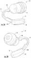
- This earbud deviceillustrated in FIG. 1C and indicated as 10 , incorporates a spring 12 to improve PPG signal quality.
- the spring 12forcibly presses the entire earbud 10 within the ear E of a subject to minimize motion of the entire earbud 10 .
- the source/sensor moduleis coupled to the entire earbud mass and, as such, may experience larger translation distances resulting in greater signal variability when the ear undergoes accelerations.
- the earbud 10is held in place with one primary spring force direction, significant discomfort can be experienced by the end user.
- the earbud motionis only constrained in one direction due to the single spring force direction.
- Some embodiments of the present inventionput a module containing one or more energy emitters and energy detectors on a biasing element, such as an elastomeric arm that decouples earbud vibration from sensor vibration. Moreover, the biasing element urges the sensor module into intimate contact with the skin surface.
- a biasing elementsuch as an elastomeric arm that decouples earbud vibration from sensor vibration. Moreover, the biasing element urges the sensor module into intimate contact with the skin surface.
- a monitoring deviceincludes a biasing element having opposite first and second end portions, and a sensing element attached to the biasing element second end portion.
- the monitoring deviceis configured to be attached to an ear of a subject such that the biasing element first end portion engages the ear at a first location and such that the sensing element is urged by the biasing member into contact with the ear at a second location.
- the sensing elementincludes at least one energy emitter configured to direct energy at a target region of the ear and at least one detector configured to detect an energy response signal from the target region or a region adjacent the target region.
- the at least one energy emitteris configured to direct electromagnetic radiation, mechanical energy, acoustical energy, electrical energy, and/or thermal energy at the target region
- the at least one detectoris configured to detect electromagnetic radiation, mechanical energy, acoustical energy, electrical energy, and/or thermal energy.
- the at least one energy emittercomprises at least one optical emitter and the at least one detector comprises at least one optical detector.
- the sensing elementincludes a surface having at least one window through which energy passes from the at least one energy emitter, and through which energy is collected by the at least one detector.
- the at least one windowmay include at least one opening.
- the surfacemay be shaped to conform to a shape of a portion of the ear of a subject.
- the sensing elementmay include a signal processor configured to receive and process signals produced by the at least one detector.
- the biasing elementmay include a motion sensor that is configured to detect motion of the biasing element and/or sensing element.
- the motion sensormay be, for example, an inertial sensor, a piezoelectric sensor, an optical sensor, etc.
- the motion sensormay be a photoplethysmography (PPG) sensor used for measuring blood flow.
- PPGphotoplethysmography
- a monitoring deviceincludes a biasing element having opposite first and second end portions, an earbud attached to the biasing element first end portion, and a sensing element attached to the biasing element second end portion.
- the earbudhas a first mass
- the sensing elementhas a second mass that is less than the first mass.
- the biasing elementis configured to urge the sensing element into contact with a portion of the ear when the earbud is inserted into the ear.
- the biasing elementdecouples motion of the earbud from the sensing element.
- the sensing elementincludes at least one energy emitter configured to direct energy at a target region of the ear and at least one detector configured to detect an energy response signal from the target region and/or a region adjacent the target region.
- the at least one energy emitteris configured to direct electromagnetic radiation, mechanical energy, acoustical energy, electrical energy, and/or thermal energy at the target region
- the at least one detectoris configured to detect electromagnetic radiation, mechanical energy, acoustical energy, electrical energy, and/or thermal energy.
- the at least one energy emittercomprises at least one optical emitter and the at least one detector comprises at least one optical detector.
- the earbudincludes an optical emitter.
- a light guide having a distal endterminates adjacent a window in a surface of the sensing element.
- the light guideis in optical communication with the optical emitter and is configured to deliver light from the optical emitter into an ear region of the subject via the light guide distal end.
- the light guideextends from the optical emitter to the sensing element at least partially through the biasing element.
- the earbudincludes an optical detector.
- a light guide having a distal endterminates adjacent a window in a surface of the sensing element.
- the light guideis in optical communication with the optical detector and is configured to collect light from an ear region of the subject via the light guide distal end and deliver collected light to the optical detector.
- the light guideextends from the optical detector to the sensing element at least partially through the biasing element.
- the sensing elementincludes a surface having at least one window through which energy passes from the at least one energy emitter, and through which energy is collected by the at least one detector.
- the at least one windowmay include at least one opening.
- the surfacemay be shaped to conform to a shape of a portion of the ear of a subject.
- the sensing elementmay include a signal processor configured to receive and process signals produced by the at least one detector.
- the biasing elementmay include a motion sensor that is configured to detect motion of the biasing element and/or sensing element.
- the motion sensormay be, for example, an inertial sensor, a piezoelectric sensor, etc.
- a speakeris disposed within the earbud, and the earbud includes at least one aperture through which sound from the speaker can pass.
- a monitoring deviceincludes a housing configured to be attached to an ear of a subject and a sensing element movably secured to the housing via a biasing element.
- the housinghas a first mass
- the sensing elementhas a second mass that is less than the first mass.
- the first massis at least 1.25 times greater than the second mass.
- the biasing elementis configured to urge the sensing element into contact with a portion of the ear, and decouples motion of the housing from the sensing element.
- the sensing elementincludes at least one energy emitter configured to direct energy at a target region of the ear and at least one detector configured to detect an energy response signal from the target region or a region adjacent the target region.
- the at least one energy emitteris configured to direct electromagnetic radiation, mechanical energy, acoustical energy, electrical energy, and/or thermal energy at the target region
- the at least one detectoris configured to detect electromagnetic radiation, mechanical energy, acoustical energy, electrical energy, and/or thermal energy.
- the at least one energy emittercomprises at least one optical emitter and the at least one detector comprises at least one optical detector.
- the biasing elementincludes a motion sensor configured to detect motion of the biasing element and/or sensing element.
- the biasing elementcomprises a flexible member that at least partially surrounds the sensing element.
- the flexible membercomprises a compressible, resilient material, such as gel.
- the monitoring deviceincludes a speaker within the housing. A sound port is formed through the flexible member and housing so as to be in acoustical communication with the speaker.
- Earbud monitoring devicesare advantageous over conventional monitoring devices for several reasons.
- Oneis comfort of fit.
- An earbud monitoring device according to embodiments of the present inventionis comfortable and may provide more accurate biometrics than conventional earbuds.
- the sensor elementas a separate body from the earbud, the earbud can be tailored for comfort.
- Another advantageis that by providing supplemental spring action on the sensor module an additional level of sensor to skin intimacy may be achieved. By decoupling the sensor module and earbud, less spring force (pressure) is needed to maintain sensor contact with the ear, thus resulting in greater comfort.
- a device where the sensorcan stay in contact with the interrogation area of interest, even under extreme accelerations, may be able to continuously report data and offer the end-user a higher confidence level in the device's accuracy.
- a monitoring deviceincludes a sensor band configured to be secured around an appendage of a subject, and a sensing element movably secured to the sensor band via a biasing element.
- the sensor bandhas a first mass
- the sensing elementhas a second mass that is less than the first mass.
- the first massis at least 1.25 times greater than the second mass.
- the biasing elementis configured to urge the sensing element into contact with a portion of the appendage, and the biasing element decouples motion of the band from the sensing element.
- the sensing elementincludes at least one energy emitter configured to direct energy at a target region of the body and at least one detector configured to detect an energy response signal from the target region or a region adjacent the target region.
- the at least one energy emitteris configured to direct electromagnetic radiation, mechanical energy, acoustical energy, electrical energy, and/or thermal energy at the target region
- the at least one detectoris configured to detect electromagnetic radiation, mechanical energy, acoustical energy, electrical energy, and/or thermal energy.
- the at least one energy emittercomprises at least one optical emitter and the at least one detector comprises at least one optical detector.
- the biasing elementincludes a motion sensor configured to detect motion of the biasing element and/or sensing element.
- the monitoring deviceincludes a second band that is configured to be secured to the appendage of the subject in adjacent, spaced-apart relationship with the sensor band. At least one member or bridge connects the sensor band and second band together.
- a monitoring deviceincludes a band that is configured to be secured around an appendage of a subject, wherein the band comprises an inner surface and an outer surface.
- a plurality of biasing elementsextend radially outward from the inner surface in circumferential spaced-apart relationship and are configured to contact the appendage.
- a sensing elementis secured to the band inner surface between two of the biasing elements.
- the sensing elementextends outwardly from the band inner surface such that the at least one energy emitter and at least one detector associated with the sensing element do not contact the appendage when the band is secured around the appendage.
- the sensing elementextends outwardly from the band inner surface such that the at least one energy emitter and at least one detector associated with the sensing element contact the appendage when the band is secured around the appendage.
- the at least one energy emitteris configured to direct electromagnetic radiation, mechanical energy, acoustical energy, electrical energy, and/or thermal energy at the target region
- the at least one detectoris configured to detect electromagnetic radiation, mechanical energy, acoustical energy, electrical energy, and/or thermal energy.
- the at least one energy emittercomprises at least one optical emitter and the at least one detector comprises at least one optical detector.
- a monitoring deviceincludes a band that is configured to be secured around an appendage of a subject and includes an inner surface and an outer surface.
- An elongated biasing element having opposite endsis secured circumferentially to the band inner surface such that the opposite ends are in adjacent, spaced-apart relationship.
- the biasing elementcomprises a surface that contacts the appendage when the band is secured around the appendage.
- a sensing elementis secured to the band inner surface between the adjacent, spaced-apart biasing element ends.
- the sensing elementincludes at least one energy emitter configured to direct energy at a target region of the appendage and at least one detector configured to detect an energy response signal from the target region or region adjacent to the target region.
- the at least one energy emitteris configured to direct electromagnetic radiation, mechanical energy, acoustical energy, electrical energy, and/or thermal energy at the target region
- the at least one detectoris configured to detect electromagnetic radiation, mechanical energy, acoustical energy, electrical energy, and/or thermal energy.
- the at least one energy emittercomprises at least one optical emitter and the at least one detector comprises at least one optical detector.
- the sensing elementincludes a surface having at least one window through which energy passes from the at least one energy emitter, and through which energy is collected by the at least one detector.
- the sensing elementextends outwardly from the band inner surface such that the at least one energy emitter and at least one detector associated with the sensing element do not contact the appendage when the band is secured around the appendage. In other embodiments, the sensing element extends outwardly from the band inner surface such that the at least one energy emitter and at least one detector associated with the sensing element contact the appendage when the band is secured around the appendage.
- one or more portions of the biasing element surfacehave a textured configuration, such as a plurality of raised bumps.
- the raised bumpsmay be arranged in an array and may have various shapes and sizes. In some embodiments, the plurality of raised bumps have alternating shapes.
- Embodiments of the present inventionutilize a sensing element as a distinct third body relative to a monitoring device and a body of a subject wearing the monitoring device.
- the monitoring deviceis an earbud configured to be secured within the ear of a subject
- the ear of the subjectis the first body
- the earbudis the second body
- the sensing element or moduleis a distinct third body.
- embodiments of the present inventionprovide several advantages over conventional monitoring devices.
- the mass of the sensing elementis reduced since the sensing element is decoupled from the earbud body. This lower mass may see smaller displacements as a result of ear, earbud or appendage accelerations, for example, as a result of subject motion.
- a sensing elementaccording to embodiments of the present invention, can be shaped and presented to the interrogation surface of interest in a form tailored for optical coupling and not restricted by conventional forms, such as conventional earbud forms.
- a biasing elementsuch as a spring
- fit within one or more portions of the concha of an earcan be achieved with an optimized earbud form, while fit between the sensor and interrogation surface can be optimized for photoplethysmography.
- any dampened systemwill have a lag in response to vibrational compensation
- decoupling the sensor element from earbud motionallows the sensor response to be better tuned to managing small vibrational offsets; whereas, the earbud dampening structures are best designed to handle larger displacements inherent from a larger, heavier mass body with multiple ear contact points.
- the earbudmakes larger amplitude acceleration compensations compared to the sensor element due to its larger mass.
- the secondary minor acceleration compensations of the sensor to ear surface (or appendage) movementmay be significantly reduced as well as signal variation.
- FIG. 1Ais a perspective view of a conventional photoplethysmography device attached to the ear of a person.
- FIG. 1Bis a perspective view of a conventional photoplethysmography device attached to a finger of a person.
- FIG. 1Cillustrates a conventional photoplethysmography device attached to the ear of a person, and wherein a biasing element is utilized to retain the photoplethysmography device in the person's ear.
- FIGS. 2A-2Care perspective views of a monitoring device having an earbud and a sensing element attached to the earbud via a biasing member, according to some embodiments of the present invention, and wherein the biasing member is configured to decouple motion of the earbud from the sensing element.
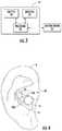
- FIG. 3schematically illustrates a sensing element utilized in monitoring devices, according to some embodiments of the present invention.
- FIG. 4illustrates the monitoring device of FIGS. 2A-2C secured within the ear of a person.
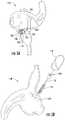
- FIG. 5Ais a perspective view of a monitoring device for attachment to an ear of a person, according to some embodiments of the present invention, and wherein a sensor module is movably secured to the housing of the monitoring device to decouple motion of the housing from the sensor module.
- FIG. 5Bis an exploded, perspective view of the monitoring device of FIG. 5A .
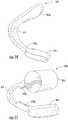
- FIG. 6illustrates elongated light guides that may be utilized with monitoring devices, according to some embodiments of the present invention, such that an optical emitter and optical detector can be located remotely from a sensing element of a monitoring device.
- FIG. 7illustrates the monitoring device of FIGS. 2A-2C with an optical emitter and detector located within the earbud and with elongated light guides extending from the optical emitter and detector to the sensing element, according to some embodiments of the present invention.
- FIG. 8illustrates a human ear with various portions thereof labeled and with the monitoring device of FIG. 11 secured therewithin.
- FIG. 9illustrates a human ear with various portions thereof labeled and with the monitoring device of FIG. 10 secured therewithin.
- FIG. 10is a perspective view of a monitoring device having a sensor module configured to be attached to an ear of a person via a biasing member, according to some embodiments of the present invention, and wherein the biasing member is configured to decouple motion of the ear from the sensor module.
- FIG. 11is a perspective view of a monitoring device having a stabilizing member configured to be inserted within an ear of a person and a sensor module attached to the stabilizing member via a biasing member, according to some embodiments of the present invention, and wherein the biasing member is configured to decouple motion of the stabilizing member from the sensor module.
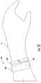
- FIG. 12illustrates a monitoring device configured to be secured to an appendage of a subject, according to some embodiments of the present invention.
- FIG. 13is a partial perspective view of the monitoring device of FIG. 12 illustrating a sensor band and a sensing element movably secured to the sensor band via a biasing element.
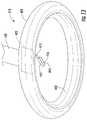
- FIG. 14illustrates a monitoring device configured to be secured to an appendage of a subject, according to some embodiments of the present invention.
- FIG. 15is a partial view of the monitoring device of FIG. 14 illustrating a sensing element secured to the band inner surface between two of the biasing elements.
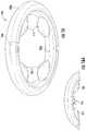
- FIG. 16illustrates a monitoring device configured to be secured to an appendage of a subject, according to some embodiments of the present invention.
- FIG. 16Ais a partial view of the monitoring device of FIG. 16 illustrating a sensing element secured to the band inner surface between two of the biasing elements.
- FIG. 17illustrates a monitoring device configured to be secured to an appendage of a subject, according to some embodiments of the present invention.
- FIG. 17Ais a partial view of the monitoring device of FIG. 17 illustrating a sensing element secured to the band inner surface.
- FIG. 17Bis a partial view of the resilient support of the monitoring device of FIG. 17 illustrating a textured surface thereof, according to some embodiments of the present invention.
- FIGS. 18A-18B and 19A-19Bare perspective views of a monitoring device having a compressible outer cover, or gel, at least partially surrounding a core monitoring device and configured to bias a sensing element in a desired region of the ear, according to some embodiments of the present invention.
- spatially relative termssuch as “under”, “below”, “lower”, “over”, “upper” and the like, may be used herein for ease of description to describe one element or feature's relationship to another element(s) or feature(s) as illustrated in the figures. It will be understood that the spatially relative terms are intended to encompass different orientations of the device in use or operation in addition to the orientation depicted in the figures. For example, if a device in the figures is inverted, elements described as “under” or “beneath” other elements or features would then be oriented “over” the other elements or features. Thus, the exemplary term “under” can encompass both an orientation of over and under.
- the devicemay be otherwise oriented (rotated 90 degrees or at other orientations) and the spatially relative descriptors used herein interpreted accordingly.
- the terms “upwardly”, “downwardly”, “vertical”, “horizontal” and the likeare used herein for the purpose of explanation only unless specifically indicated otherwise.
- first and secondare used herein to describe various features/elements, these features/elements should not be limited by these terms. These terms are only used to distinguish one feature/element from another feature/element. Thus, a first feature/element discussed below could be termed a second feature/element, and similarly, a second feature/element discussed below could be termed a first feature/element without departing from the teachings of the present invention.
- Like numbersrefer to like elements throughout.
- monitoring deviceincludes any type of device that may be attached to or near the ear or to an appendage of a user and may have various configurations, without limitation.
- the term “real-time”is used to describe a process of sensing, processing, or transmitting information in a time frame which is equal to or shorter than the minimum timescale at which the information is needed.
- the real-time monitoring of pulse ratemay result in a single average pulse-rate measurement every minute, averaged over 30 seconds, because an instantaneous pulse rate is often useless to the end user.
- averaged physiological and environmental informationis more relevant than instantaneous changes.
- signalsmay sometimes be processed over several seconds, or even minutes, in order to generate a “real-time” response.
- monitoringrefers to the act of measuring, quantifying, qualifying, estimating, sensing, calculating, interpolating, extrapolating, inferring, deducing, or any combination of these actions. More generally, “monitoring” refers to a way of getting information via one or more sensing elements.
- blood health monitoringincludes monitoring blood gas levels, blood hydration, and metabolite/electrolyte levels.
- physiologicalrefers to matter or energy of or from the body of a creature (e.g., humans, animals, etc.).
- the term “physiological”is intended to be used broadly, covering both physical and psychological matter and energy of or from the body of a creature.
- the term “psychological”is called-out separately to emphasize aspects of physiology that are more closely tied to conscious or subconscious brain activity rather than the activity of other organs, tissues, or cells.
- bodyrefers to the body of a subject (human or animal) that may wear a monitoring device, according to embodiments of the present invention.
- the earis an ideal location for wearable health and environmental monitors.
- the earis a relatively immobile platform that does not obstruct a person's movement or vision.
- Monitoring devices located at an earhave, for example, access to the inner-ear canal and tympanic membrane (for measuring core body temperature), muscle tissue (for monitoring muscle tension), the pinna, earlobe, and elsewhere (for monitoring blood gas levels), the region behind the ear (for measuring skin temperature and galvanic skin response), and the internal carotid artery (for measuring cardiopulmonary functioning), etc.
- the earis also at or near the point of exposure to: environmental breathable toxicants of interest (volatile organic compounds, pollution, etc.; noise pollution experienced by the ear; and lighting conditions for the eye.
- the ear canalis naturally designed for transmitting acoustical energy, the ear provides a good location for monitoring internal sounds, such as heartbeat, breathing rate, and mouth motion.
- Optical coupling into the blood vessels of the earmay vary between individuals.
- the term “coupling”refers to the interaction or communication between excitation energy (such as light) entering a region and the region itself.
- excitation energysuch as light
- one form of optical couplingmay be the interaction between excitation light generated from within a light-guiding earbud and the blood vessels of the ear. In one embodiment, this interaction may involve excitation light entering the ear region and scattering from a blood vessel in the ear such that the temporal change in intensity of scattered light is proportional to a temporal change in blood flow within the blood vessel.
- Another form of optical couplingmay be the interaction between excitation light generated by an optical emitter within an earbud and the light-guiding region of the earbud.
- an earbud with integrated light-guiding capabilitiescan assure that each individual wearing the earbud will generate an optical signal related to blood flow through the blood vessels.
- Optical coupling of light to a particular ear region of one personmay not yield photoplethysmographic signals for each person. Therefore, coupling light to multiple regions may assure that at least one blood-vessel-rich region will be interrogated for each person wearing the light-guiding earbud. Coupling multiple regions of the ear to light may also be accomplished by diffusing light from a light source within the earbud.
- the illustrated monitoring device 10includes a biasing element 12 having opposite first and second end portions 12 a , 12 b .
- An earbud 14is attached to the biasing element first end portion 12 a
- a sensing element 16is attached to the biasing element second end portion 12 b .
- the sensing element 16may comprise sensor components and may preferably be smaller in mass than the mass of the earbud 14 , and may be substantially less.
- the earbud massmay be at least 10% greater than the sensing element mass, may be at least 20% greater than the sensing element mass, may be at least 30% greater than the sensing element mass, may be at least 40% greater than the sensing element mass, may be at least 50% greater than the sensing element mass, may be at least 60% greater than the sensing element mass, may be at least 70% greater than the sensing element mass, may be at least 80% greater than the sensing element mass, may be at least 90% greater than the sensing element mass, may be at least 100% greater than the sensing element mass, may be 200% or more than the sensing element mass, etc.
- the mass of the earbudis preferably larger than that of the sensor element by a sufficient degree so that the earbud serves as the primary frame of reference (the mechanical support reference) for the monitoring device.
- Substantial motion decouplingcan be achieved by the sensing element 16 having a mass that is smaller than the mass of the earbud 14 .
- the momentum caused by the monitoring device 10 acceleratingmay be substantially less on the sensing element 16 such that the sensing element 16 experiences less distance travelled.
- Sensor noiseis reduced by stopping the monitoring device 10 momentum from causing the sensing element 16 to move as far.
- Sensor jitter from movementis the largest controllable contributor to a noisy signal. The more one can decouple device mass from sensor mass the cleaner the signal gets. The more the sensing element 16 mass is reduced and the lower the spring constant, the less sensor movement is experienced from the monitoring device 10 mass accelerating on each footstep of the subject, for example.
- the monitoring device 10is configured to be attached to an ear of a subject such that the earbud 14 is secured within the ear and the biasing element 12 urges the sensing element 16 into contact with the ear at a particular location, for example, as illustrated in FIG. 4 .
- the biasing element 12decouples motion of the larger mass earbud 14 from the smaller mass sensing element 16 .
- the motion of sensing element 16is more closely tied to the motion of the subject and less tied to the motion of the earbud, for example when the subject is exercising or undergoing other motion.
- the motion between the sensing element 16 and the subjectmay be less than the motion between the sensing element 16 and the earbud 14 .
- the earbud 14may have various shapes and configurations and is not limited to the illustrated shape.
- the sensing element 16may have various shapes and configurations and is not limited to the illustrated shape.
- a wire(not shown) may connect an audio device to the earbud, as would be understood by those of skill in the art.
- the earbud 14may comprise a speaker, and/or the monitoring device 10 may generally comprise a speaker and microphone.
- Various types of speakers or microphonesmay be used. In some cases a bone conduction microphone or speaker may be used.
- a speakermay intentionally not be present and an opening or hole may exist in the earbud to expose the ear canal to the outside world. Such an embodiment may be useful for the case where biometric/physiological monitoring is desired without the user's ear canal being blocked-off from ambient sounds.
- FIG. 4illustrates the monitoring device 10 of FIGS. 2A-2C secured within the ear of a person.
- the sensing element 16includes at least one energy emitter 20 ( FIG. 3 ) configured to direct energy at a target region of the ear (or for other embodiments of the present invention, at a target region of another portion of the body of a subject, such as an appendage) and at least one detector 22 ( FIG. 3 ) configured to detect an energy response signal from the target region and/or a region adjacent the target region.
- the at least one energy emitter 20is configured to direct electromagnetic radiation, mechanical energy, acoustical energy, electrical energy, and/or thermal energy at the target region
- the at least one detector 22is configured to detect electromagnetic radiation, mechanical energy, acoustical energy, electrical energy, and/or thermal energy.
- the at least one energy emittercomprises at least one optical emitter and the at least one detector comprises at least one optical detector.
- Exemplary optical detectorsinclude, but are not limited to photodiodes, photodetectors, phototransistors, thyristors, solid state devices, optical chipsets, whether analog or digital, or the like. Many types of compact optical detectors exist in the marketplace today and comprise various well-known methods of generating analog or digital outputs.
- Exemplary optical emittersinclude, but are not limited to light-emitting diodes (LEDs), laser diodes (LDs), compact incandescent bulbs, micro-plasma emitters, IR blackbody sources, or the like.
- Some emitters, detectors, or emitter-detector modulesmay also comprise one or more processors 26 for signal conditioning, ND conversion, voltage-to-frequency conversion, level translation, and general signal processing of signals from the detector. Additionally, one or more processors 26 may be used to control the powering (electrical biasing) of the emitters and/or detectors. A few examples are provided in U.S. Patent Application Publication No. 2012/0197093, which is incorporated herein by reference in its entirety. In some embodiments, the processor 26 may not be located within the sensing element 16 itself and may even be located outside of the monitoring device 10 altogether, as long as the processor 26 is in electrical communication with the sensing element 16 . Moreover, processor 26 may represent multiple processors distributed within the monitoring device 10 and/or outside of the monitoring device 10 .
- the energymay be pulsed energy generated by an energy emitter 20 .
- a pulsed driving circuit(not shown) may be used to drive at least one energy emitter 20 at one or more pulsed frequencies to interrogate a target region with pulsed energy.
- An energy response caused by this interactionis detected by at least one detector 22 , which is configured to detect energy in the forms described above, but typically in the form of scattered optical energy.
- a motion/position sensor 24may be configured to measure movement, positional changes, or inertial changes in the vicinity of the target region, such as gross body motion, skin motion, or the like.
- the motion/position sensor 24may be located within the sensing element.
- the biasing element 12may include a motion/position sensor 24 that is configured to detect motion of the biasing element 12 and/or sensing element 16 , or the relative motion between the earbud 14 and sensing element 16 .
- the motion/position sensor 24may also serve as a noise reference by a neighboring or remote processor (such as processor 26 ) for attenuating or removing motion noise from physiological signals picked up by the detector 22 .
- Noise attenuation and removalis described in detail in U.S. Pat. Nos. 8,157,730, 8,251,903, U.S. Patent Application Publication No. 2008/0146890, U.S. Patent Application Publication No. 2010/0217098, U.S. Patent Application Publication No. 2010/0217102, U.S. Provisional Patent Application No. 61/750,490, PCT Application No. US2012/071593, PCT Application No. US2012/071594, and PCT Application No. US2012/048079, which are incorporated herein by reference in their entireties.
- the monitoring device 10includes a signal processor 26 ( FIG. 3 ) that is configured to receive and process signals produced by the at least one detector 16 .
- the monitoring device 10may include other components such as one or more analog-to-digital convertors (not shown) for the output of the at least one detector 22 , one or more filters such as optical filters (snot shown) for removing the effects of time-varying environmental interference, one or more analog and/or digital filters for removing motion artifacts in an energy response signal, passive electronic components, etc., as would be understood by one skilled in the art.
- the monitoring device 10may include various other devices, such as other types of physiological sensors and environmental sensors (not shown).
- the monitoring device 10may also include at least one wireless module (not shown) for communicating with a remote device, and/or at least one memory storage device (not shown).
- An exemplary wireless modulemay include a wireless chip, antenna, or RFID tag.
- the wireless modulemay include a low-range wireless chip or chipset, such as a Bluetooth®, ANT+, and/or ZigBee chip.
- a battery(not shown), such as a lithium polymer battery or other portable battery, may be included within the monitoring device 10 and may be charged via a USB charge port, for example.
- the sensing element 16includes a surface 30 that engages a portion of the ear E of a subject. In some embodiments, at least part of the surface 30 may be contoured to conform to a shape of a portion of the ear of a subject. Also, in the illustrated embodiment of FIGS. 2A-2C , one or more energy emitters 20 and detectors 22 are located within the sensing element 16 . A pair of windows 32 , 34 are included in the illustrated sensing element surface 30 through which energy passes from the one or more energy emitters 22 , and through which energy is collected by the one or more detectors 22 . Each window 32 , 34 is formed from a material that allows energy to pass therethrough.
- the windows 32 , 34are formed from material that allows light to pass therethrough.
- the windows 32 , 34may include one or more openings.
- a single windowis utilized instead of a pair of windows.
- the windows 32 , 34 illustrated in FIG. 2Cmay be shown as flush with the overall sensor surface 30 , it should be noted that the windows 32 , 34 at the sensor surface 30 may be recessed with respect to the sensor surface 30 and may not come into physical contact with the skin of the ear of a user of the monitoring device 10 .
- a flush, protruding, or recessed window(s) ( 32 , 34 )may be acceptable.
- the window(s) ( 32 , 34 )in some embodiments may comprise air such that the excitation energy entering or leaving the sensor element 16 may pass through air.
- one or both of the windows 32 , 34may be in optical communication with an optical lens (not shown).
- the lensmay be configured to focus light emitted by an optical emitter onto one or more portions of an ear and/or to focus collected light on a detector.
- Various types of lens geometriesmay be employed, such as concave, convex, collimating, and the like.
- Light guides(such as light pipes, fiber optics, or the like) may also be incorporated for this stated purpose. Exemplary light guides and sensing element geometries that may be utilized in accordance with some embodiments of the present invention are described, for example, in U.S. Patent Application Publication No. 2010/0217102, U.S. Patent Application Publication No. 2013/0131519, and U.S. Patent Application Publication No. 2010/0217098, which are incorporated herein by reference in their entireties.
- an optical energy emitter 20 and/or optical detector 22may be located within the monitoring device 10 , in the earbud 14 or sensing element 16 .
- One or more light guidesare utilized to deliver light from the optical emitter into an ear region of the subject via the light guide distal end, and/or to collect light from an ear region of the subject via the light guide distal end and deliver collected light to the optical detector.
- FIGS. 5A and 5Billustrate a monitoring device 110 , according to other embodiments of the present invention.
- the monitoring device 110includes a housing 114 configured to be attached to an ear of a subject, and a sensing element 116 movably secured to the housing 114 via a biasing element 112 (e.g., a coil spring, or other substantially compressible structure or material, etc.).
- the biasing element 112may include a motion sensor (not shown) that is configured to detect motion of the biasing element 112 and/or sensing element 116 .
- the biasing element 112may have a spring constant between about 0.1 N/m and about 200 N/m. If a resilient material is utilized as the biasing element 112 , the resilient material may have a durometer range from about 10 (Type OO-ASTM D2240) to 80 (Type A-ASTM D2240), and a hardness range of about 20-50 Shore A. Exemplary springs that may be utilized as the biasing element 112 can be molded from acetal, polyester, polyetherimide, or another suitable polymer, or could be formed from metal, such as steel. Exemplary spring manufacturers include, but are not limited to, Lee Spring (Greensboro, N.C.) and Century Spring Corp. (Los Angeles, Calif.).
- An exemplary resilient material that may be used as a biasing elementincludes, but is not limited to, silicone (Dow Corning Corp., Midland, Mich.). However, various other materials may be used, such as stretchy neoprene (polyurethane).
- the illustrated sensing element 116includes a printed circuit board (PCB) 123 with an optical emitter 120 and an optical detector 122 attached thereto.
- the PCB 123also includes an elongated guide rod 125 that is inserted within the illustrated biasing element 112 .
- the preferred direction of emission lightis the region between the anti-tragus and concha of the ear as described, for example, in U.S. Patent Application Publication No. 2010/0217098, U.S. Patent Application Publication No. 2010/0217102, and also in U.S. Patent Application Publication No. 2013/0131519 which is incorporated herein by reference in its entirety.
- optically reflective walls 126are positioned to direct light towards the region between the anti-tragus and concha of the ear.
- the monitoring device 110also includes a cover 118 for the sensing element 116 .
- the cover 118may be transmissive to energy (e.g., electromagnetic radiation, acoustical energy, electrical energy, and/or thermal energy, etc.) emitted by an emitter associated with the sensing element 116 and energy detected by a detector associated with the sensing element 116 .
- energye.g., electromagnetic radiation, acoustical energy, electrical energy, and/or thermal energy, etc.
- the cover 118may be transmissive to optical wavelengths of the optical emitter and detector.
- the cover 118may also include reflective surfaces or walls 126 to facilitate directing energy from the emitter 120 toward the ear of a user and directing energy from the ear to the detector 122 .
- the angle of the reflective wall(s) 126 with respect to the axis of the elongated rod 125is shown at approximately forty-five degrees (45°) in FIG. 5A , but this should not be considered limiting.
- the angle of the reflective walls 126will depend primarily on the direction of the emission/detection face of the optical emitter/detector with respect to the region between the anti-tragus and concha of the ear. For example, if the emitter 120 and detector 122 are directed with their respective emission/detection faces located in the direction of the anti-tragus, the angle of the reflective surface(s) 126 may be ninety degrees (90°) with respect to the axis of the elongated rod 125 .
- the illustrated cover 118is attached to the sensing element 116 and moves with the sensing element.
- the cover 118can be attached to the sensing element 116 in various ways.
- the cover 118may be overmolded onto the sensing element 116 such that the cover at least partially conforms to the shape of the sensing element 116 components.
- the cover 118may be attached with a suitable transmissive adhesive.
- Exemplary adhesive materialsinclude, but are not limited to, glue, tape, resin, gel, filler material, molded material, etc.
- the cover 118is attached to the sensing element 116 via heatstaking, one or more mechanical fasteners, or other suitable methods.
- the sensing element 116 and cover 118may comprise an integrated unit (via overmold and/or adhesive) that can be connected to the rod 123 or spring 112 .
- an optical filtermay be placed over the emitter 120 or detector 122 in one or more ways, for example, as described in U.S. Patent Application Publication No. 2010/0217098, U.S. Patent Application Publication No. 2010/0217102, U.S. Patent Application Publication No. 2013/0131519, and U.S. Patent Application Publication No. 2012/0197093.
- the cover 118may comprise an optical filter or optical dye focused on the wavelength of interest, which is chiefly determined by the choice of the optical emitter 120 .
- the optical filtermay be tuned to the infrared range centered around 940 nm.
- onemay use GENTEX-E800 dye dispersed in a polycarbonate or acrylic cover 118 .
- the housing 114 of the monitoring device 110has a much larger mass than the sensing element 116 and cover 118 , and the biasing element 112 decouples motion of the housing 114 from the sensing element 116 and cover 118 .
- the monitoring device 110includes a signal processor 26 ( FIG. 3 ) that is configured to receive and process signals produced by the optical detector 122 .
- the monitoring device 110may include other components such as one or more analog-to-digital convertors (not shown) for the output of the optical detector 122 , one or more filters such as optical filters (not shown) for removing the effects of time-varying environmental interference, one or more analog and/or digital filters for removing motion artifacts in an energy response signal, passive electronic components, etc., as would be understood by one skilled in the art.
- the monitoring device 110may include various other devices, such as other types of physiological sensors and environmental sensors (not shown).
- the monitoring device 110may also include at least one wireless module (not shown) for communicating with a remote device, and/or at least one memory storage device (not shown).
- An exemplary wireless modulemay include a wireless chip, antenna, or RFID tag.
- the wireless modulemay include a low-range wireless chip or chipset, such as a Bluetooth®, ANT+, and/or ZigBee chip.
- a battery(not shown), such as a lithium polymer battery or other portable battery, may be included within the monitoring device 110 and may be charged via a USB charge port, for example.
- FIGS. 18A-18B and 19A-19Billustrate a monitoring device 710 configured to be attached to an ear of a subject, according to other embodiments of the present invention.
- the monitoring device 710includes a housing 714 , a core element 718 , and a sensing element 716 .
- a sound port 720is formed in the core element and is in acoustic communication with a speaker (not shown) within the housing 714 .
- the sensing element 716may include all of the functionality of the sensing device 16 described above.
- the sensing element 716may include at least one energy emitter 20 ( FIG. 3 ) configured to direct energy at a target region of the ear and at least one detector 22 ( FIG. 3 ) configured to detect an energy response signal from the target region or a region adjacent the target region, as described above, to sense physiological signals from the body of the subject.
- the cover 818at least partially surrounds the sensing element 716 , and serves as a biasing element that decouples motion of the housing 714 and core element 718 from the sensing element 716 .
- the illustrated cover 818has a sound port 820 formed therethrough that is in acoustic communication with sound port 720
- the monitoring device 710includes an arcuate resilient member 822 that is configured to stabilize the monitoring device 710 within the ear of a subject, as would be understood by one skilled in the art.
- an arcuate resilient member 822that is configured to stabilize the monitoring device 710 within the ear of a subject, as would be understood by one skilled in the art.
- Numerous types of stabilizersalso referred to as covers, tips, or housings that may be utilized as member 822 are well known in the art, (e.g., see U.S. Patent Application Publication No. 2010/0217098, U.S. Patent Application Publication No. 2010/0217102, and U.S. Patent Application Publication No. 2012/0197093) each finding various points of reference for holding an earbud within the ear.
- the illustrated monitoring device 710also includes an additional flexible member 824 formed from a compressible/resilient material, such as a gel material, etc.
- This flexible member 824is attached to the cover 818 and extends below the plane of the sensing element 816 , such that the sensing element 816 is recessed within the flexible member 824 .
- the flexible member 824effectively extends the cover 818 so that it can compress in the region including, and in between, the anti-tragus and crus helix of a subject's ear.
- a barrier between the emitter and detectormay also be preserved as the flexible member 824 extends to prevent optical cross-talk between the emitter and detector of the sensing element 716 .
- the flexible member 824serves as a biasing element that decouples motion of the housing 714 and core element 718 from the sensing element 716 .
- the illustrated monitoring device 710effectively includes two biasing elements that facilitate the decoupling of motion of the housing 714 and core element 718 from the sensing element 716 : flexible cover 818 and flexible member 824 .
- the monitoring device 710includes a signal processor 26 ( FIG. 3 ) that is configured to receive and process signals produced by the at least one detector 22 .
- the monitoring device 710may include other components such as one or more analog-to-digital convertors (not shown) for the output of the at least one detector 22 , one or more filters such as optical filters (not shown) for removing the effects of time-varying environmental interference, one or more analog and/or digital filters for removing motion artifacts in an energy response signal, passive electronic components, etc., as would be understood by one skilled in the art.
- the monitoring device 710may include various other devices, such as other types of physiological sensors and environmental sensors (not shown).
- the monitoring device 710may also include at least one wireless module (not shown) for communicating with a remote device, and/or at least one memory storage device (not shown).
- An exemplary wireless modulemay include a wireless chip, antenna, or RFID tag.
- the wireless modulemay include a low-range wireless chip or chipset, such as a Bluetooth®, ANT+, and/or ZigBee chip.
- a battery(not shown), such as a lithium polymer battery or other portable battery, may be included within the monitoring device 710 and may be charged via a USB charge port, for example.
- an optical emitter 20 and optical detector 22are attached to or disposed within the sensing element 16 .
- an optical emitter 20 and/or optical detector 22can be located remotely from the sensing element 16 .
- an optical emitter 20 and optical detector 22may be located within the earbud 14 .
- a pair of elongated light guides 130such as illustrated in FIG. 6 , are in optical communication with the optical emitter 20 and optical detector 22 via proximal end portions 130 b and extend from the optical emitter 20 and optical detector 22 at least partially through the biasing element 12 to the sensing element 16 .
- the sensing element 16includes a pair of windows 32 , 34 in the surface 30 thereof. Each light guide distal end 130 a is positioned adjacent a respective window 32 , 34 , as illustrated. As such, the light guide 130 in optical communication with the optical emitter 20 can deliver light from the optical emitter 20 into an ear region of the subject, and the light guide 130 in optical communication with the optical detector 22 can collect light from the ear region of the subject and deliver collected light to the optical detector 22 .
- the distance between the sensing element windows 32 and 34is long enough to reduce optical backscatter noise and close enough to emit and detect light from a target region and/or a region adjacent the target region. Distances on the order of millimeters have been found to be ideal in practice. Moreover, the material between windows 32 , 34 is sufficiently optically opaque to reduce cross-talk between the emitter 20 and detector 22 .
- Each light guide 130may be formed from various types of light transmissive material, typically with a refractive index greater than about 1.1.
- a light guide 130may be formed from an elastomeric light transmissive material.
- Exemplary light guide materialsinclude, but are not limited to, polycarbonate, acrylic, silicone, and polyurethane.
- a light guide 130may be surrounded or partially surrounded by a cladding material that is configured to block light from an external source, such as room light, sunlight, etc., from entering the light guide 130 .
- the distal free end surface 130 c of each light guide 130may have a variety of shapes and/or configurations, more than exemplarily shown in FIG. 6 .
- Various types and configurations of light guidesmay be utilized, for example, as described in U.S. Patent Application Publication No. 2010/0217102 and U.S. Patent Application Publication No. 2013/0131519.
- optical coupling material 132may be applied to one or both of the optical emitter 20 and optical detector 22 .
- a light guide 130is in optical communication with the optical emitter 20 and optical detector 22 via the optical coupling material 132 .
- the optical coupling material 132may comprise a material that effectively couples light from the optical emitter 20 to the light guide 130 or from the light guide 130 to the optical detector 22 .
- suitable materialsinclude, but are not limited to, glue, epoxy, tape, resin, gel, oil, filler material, molded material (such as a plastic, acrylic, and/or polycarbonate) or the like.
- the sensing element 16may have one or more windows 32 , 34 in the surface 30 thereof and the distal free end surface 130 c of one or both of the light guides 130 may extend to the windows 32 , 34 .
- one or both of the windows 32 , 34may be apertures formed through the surface 30 and the distal free end surface 130 c of one or both of the light guides 130 may extend to or through the apertures.
- the illustrated monitoring device 210includes a biasing element 212 having opposite first and second end portions 212 a , 212 b .
- a sensing element 216is attached to the biasing element second end portion 212 b .
- the monitoring device 210is configured to be attached to an ear E of a subject such that the biasing element first end portion 212 a engages the ear at a first location and such that the sensing element is urged by the biasing member into contact with the ear at a second location, as illustrated in FIG. 9 .
- the sensing element 216may include all of the functionality of the sensing device 16 described above with respect to FIGS.
- the sensing element 216may include at least one energy emitter 20 ( FIG. 3 ) configured to direct energy at a target region of the ear and at least one detector 22 ( FIG. 3 ) configured to detect an energy response signal from the target region or a region adjacent the target region, as described above, to sense physiological signals from the body of the subject.
- the monitoring device 210includes a signal processor 26 ( FIG. 3 ) that is configured to receive and process signals produced by the at least one detector 22 .
- the monitoring device 210may include other components such as one or more analog-to-digital convertors (not shown) for the output of the at least one detector 22 , one or more filters such as optical filters (not shown) for removing the effects of time-varying environmental interference, one or more analog and/or digital filters for removing motion artifacts in an energy response signal, passive electronic components, etc., as would be understood by one skilled in the art.
- the monitoring device 210may include various other devices, such as other types of physiological sensors and environmental sensors (not shown).
- the monitoring device 210may also include at least one wireless module (not shown) for communicating with a remote device, and/or at least one memory storage device (not shown).
- An exemplary wireless modulemay include a wireless chip, antenna, or RFID tag.
- the wireless modulemay include a low-range wireless chip or chipset, such as a Bluetooth®, ANT+, and/or ZigBee chip.
- a battery(not shown), such as a lithium polymer battery or other portable battery, may be included within the monitoring device 210 and may be charged via a USB charge port, for example.
- the illustrated embodiment of FIG. 10does not utilize an earbud portion (e.g., 14 , FIGS. 2A-2C ) or a stabilization member ( 314 , FIG. 11 ) for support within the ear.
- the first end portion 212 a of the monitoring device 210 illustrated in FIG. 10may be supported within the ear primarily by the ear region including, and in between, the anti-helix and crus helix, as shown in FIG. 9 .
- the first end portion 212 amay be supported primarily by the ear region including, and in between, the crus helix and acoustic meatus.
- the first end portion 212 a and second end portion 212 bmay be supported by geometrically opposing ear features.
- the monitoring device 210may be oriented within a subject's ear in various ways.
- the sensing element 216 locationmay be “flipped”.
- the second end portion 212 bmay be supported by the ear region including, and in between, the anti-helix and crus helix
- the first end portion 212 amay be supported by the ear region including, and in between, the crus helix and anti-tragus.
- the sensing element 216may rest against the anti-helix of the ear rather than the anti-tragus.
- the anti-helixmay have substantially less blood flow than that of the anti-tragus, it may present less motion artifacts for some user activities, and so this configuration may be useful for some physiological monitoring applications.
- the illustrated monitoring device 310includes a biasing element 312 having opposite first and second end portions 312 a , 312 b .
- a stabilization member 314that is configured to be at least partially inserted into the ear or ear canal is attached to the biasing element first end portion 312 a .
- the stabilization member 314may not contain a speaker and may not serve the function of an audio earbud.
- the stabilization member 314may have a hole completely through one or more axes to allow sound to freely pass from the environment to the eardrum of the subject wearing the monitoring device 310 .
- the stabilization member 314facilitates attachment of the monitoring device 310 to an ear of a subject.
- the monitoring devices 210 and 310may be particularly useful for subjects who want to monitor their vital signs but do not want to listen to music or do not want to have their ear canal blocked-off from sound. Additionally, if constructed with waterproof housing, the monitoring devices 210 and 310 may be especially suited for swimmers who may not want to hear sound from speakers during physiological monitoring.
- a sensing element 316is attached to the biasing element second end portion 312 b .
- the monitoring device 310is configured to be attached to an ear E of a subject such that the sensing element 316 is urged by the biasing member 312 into contact with the ear, as illustrated in FIG. 8 .
- the sensing element 316may include all of the functionality of the sensing device 16 described above.
- the sensing element 316may include at least one energy emitter 20 ( FIG. 3 ) configured to direct energy at a target region of the ear and at least one detector 22 ( FIG. 3 ) configured to detect an energy response signal from the target region or a region adjacent the target region, as described above, to sense physiological signals from the body of the subject.
- the sensing element 316may be preferably biased to direct and/or detect energy from the region of the ear between the anti-tragus and concha of the ear, as this region has been found to provide a sufficiently high blood flow signal intensity while also being resilient to motion artifacts.
- the monitoring device 310includes a signal processor 26 ( FIG. 3 ) that is configured to receive and process signals produced by the at least one detector 22 .
- the monitoring device 310may include other components such as one or more analog-to-digital convertors (not shown) for the output of the at least one detector 22 , one or more filters such as optical filters (not shown) for removing the effects of time-varying environmental interference, one or more analog and/or digital filters for removing motion artifacts in an energy response signal, passive electronic components, etc., as would be understood by one skilled in the art.
- the monitoring device 310may include various other devices, such as other types of physiological sensors and environmental sensors (not shown).
- the monitoring device 310may also include at least one wireless module (not shown) for communicating with a remote device, and/or at least one memory storage device (not shown).
- An exemplary wireless modulemay include a wireless chip, antenna, or RFID tag.
- the wireless modulemay include a low-range wireless chip or chipset, such as a Bluetooth®, ANT+, and/or ZigBee chip.
- a battery(not shown), such as a lithium polymer battery or other portable battery, may be included within the monitoring device 310 and may be charged via a USB charge port, for example.
- the small size of the monitoring devices 210 and 310may preclude space for signal processing electronics ( 26 ) and battery power. For this reason, these monitoring devices may also be attached/wired to additional structures that house necessary electronics and/or battery power. Various configurations can be used for these additional structures and are well known to those skilled in the art. For example, the monitoring devices 210 , 310 may be wired to a smartphone, wireless “medallion”, and/or MP3-player for powering, signal processing, or audiovisual communication. Moreover, at least some of the electronics illustrated in FIG. 3 may be located in such additional structures, rather than in the monitoring devices 210 , 310 , themselves.
- the illustrated monitoring device 410includes a sensor band 420 configured to be secured to an appendage A (e.g., an arm, wrist, hand, finger, toe, leg, foot, neck, etc.) of a subject, and a sensing element 416 movably secured to the sensor band 420 via a biasing element 412 .
- the biasing element 412is configured to urge the sensing element 416 into contact with a portion of the appendage A.
- the biasing element 412decouples motion of the sensor band 420 from the sensing element 416 .
- the sensor band 420has a first mass, and the sensing element 416 has a second mass that is less than the first mass.
- the sensor band massmay be at least 10% greater than the sensing element mass, may be at least 20% greater than the sensing element mass, may be at least 30% greater than the sensing element mass, may be at least 40% greater than the sensing element mass, may be at least 50% greater than the sensing element mass, may be at least 60% greater than the sensing element mass, may be at least 70% greater than the sensing element mass, may be at least 80% greater than the sensing element mass, may be at least 90% greater than the sensing element mass, may be at least 100% greater than the sensing element mass, may be 200% or more than the sensing element mass, etc.
- the mass of the sensor bandis preferably larger than that of the sensing element by a sufficient degree so that the sensor band serves as the primary frame of reference (the mechanical support reference) for the monitoring device.
- the sensing element 416may include all of the functionality of the sensing device 16 described above.
- the sensing element 416may include at least one energy emitter 20 ( FIG. 3 ) configured to direct energy at a target region of the appendage A and at least one detector 22 ( FIG. 3 ) configured to detect an energy response signal from the target region or a region adjacent the target region, as described above, to sense physiological signals from the body of the subject.
- the biasing element 412includes a motion sensor (e.g., 24 , FIG. 3 ) configured to detect motion of the biasing element and/or sensing element 416 .
- the monitoring device 410includes a signal processor 26 ( FIG. 3 ) that is configured to receive and process signals produced by the at least one detector 22 .
- the monitoring device 410may include other components such as one or more analog-to-digital convertors (not shown) for the output of the at least one detector 22 , one or more filters such as optical filters (not shown) for removing the effects of time-varying environmental interference, one or more analog and/or digital filters for removing motion artifacts in an energy response signal, passive electronic components, etc., as would be understood by one skilled in the art.
- the monitoring device 410may include various other devices, such as other types of physiological sensors and environmental sensors (not shown).
- the monitoring device 410may also include at least one wireless module (not shown) for communicating with a remote device, and/or at least one memory storage device (not shown).
- An exemplary wireless modulemay include a wireless chip, antenna, or RFID tag.
- the wireless modulemay include a low-range wireless chip or chipset, such as a Bluetooth®, ANT+, and/or ZigBee chip.
- a battery(not shown), such as a lithium polymer battery or other portable battery, may be included within the monitoring device 410 and may be charged via a USB charge port, for example.
- light guides and associated opticsmay be integrated into the sensing element 416 (and 516 , FIG. 14 ).
- the sensing element 416may additionally include at least one energy emitter and/or at least one energy detector configured to primarily sense the motion the sensor element 416 itself, such that, utilizing a processor (e.g., 26 , FIG. 3 ), this motion signal can provide a suitable motion noise reference for attenuating motion noise from the physiological signals collected by the sensing element 416 .
- the sensor element 416may include a top portion 441 and an opposite bottom portion 443 .
- An energy emitter and/or detectormay be located on the bottom portion 443 to sense physiological information from the appendage of a subject wearing the monitoring device 410 , and an energy emitter and/or detector may be located on the top portion 441 to sense motion of the sensor element 416 with respect to the sensor band 420 , counterweight 422 , and/or inner surface 442 of the sensor band 420 .
- Energy scattered between the top portion 441 of the sensor element 416 and inner surface 442 of the sensor band 420may coincide with motion between these two surfaces (i.e., sensing element top portion 441 and sensor band inner surface 442 ), and this information may be used as a noise reference for motion noise attenuation as aforementioned.
- an emitter and/or detectormay alternatively be disposed on the inner surface 442 of the sensor band 420 , rather than on the top portion 441 of the sensor element 416 , or there may be at least one emitter and detector disposed between the inner surface 442 and sensing element top portion 441 .
- energyis emitted by at least one energy emitter disposed on at least one face (i.e., sensor band inner surface 442 , sensing element top portion 441 ), is modulated in intensity by motion (displacement) between the two portions (i.e., sensor band inner surface 442 , sensing element top portion 441 ), and is detected by an energy detector disposed on at least one of the two portions (i.e., sensor band inner surface 442 , sensing element top portion 441 ).
- an energy detectordisposed on at least one of the two portions (i.e., sensor band inner surface 442 , sensing element top portion 441 ).
- the monitoring device 410may include a second band 430 that is configured to be secured to the appendage A of the subject in adjacent, spaced-apart relationship with the sensor band 420 .
- At least one connecting member or bridge 432connects the sensor band and second band.
- the purpose of the bridge 432is to at least partially decouple motion between the sensor band 420 and second band 430 .
- a plurality of connecting members 432may be utilized, without limitation.
- the at least one connecting member 432may be placed at a distance from the sensing element 416 to increase decoupling of motion of the sensor band 420 from the sensing element 416 .
- Adding a second band 430may not be required for overall physiological sensing; however, having a second band 430 may help in further decoupling the sensing element 416 from the motion of other essential electronics surrounding the appendage.
- the second band 430may contain a power source (e.g., a battery, etc.) and various heavier electronic components.
- the second band 430may have a mass that is greater than the mass of the sensor band 420 which, in turn, may have a mass greater than that of the sensing element 416 .
- a counterweight 422may be embedded within, or otherwise attached to, the sensor band 420 to help keep the sensing element 416 pressed into the appendage A of the subject.
- the counterweight 422may be located in an area of the sensor band 420 that is opposite that of the sensing element 416 .
- the counterweight 422may be a distributed weight that is distributed according to a mathematical function factoring the distance from the sensing element 416 .
- the density of the counterweight 422may be proportional to the radial distance away from the sensing element 416 such that the peak density is in an area of the sensor band 420 that is opposite that of the sensing element 416 .
- the counterweight 422can be virtually any material that can be structurally supported by the sensor band 420 .
- the counterweight 422may be a greater total mass of plastic used in the housing of the sensor band 420 , or a higher density plastic.
- a light guidemay transmit light to the second band 430 through the connecting member 432 , such that the emitter and/or detector electronics may also be located on the second band 430 . This may further reduce the overall mass of the sensing element 416 and/or sensor band 420 .
- one or more motion sensorsmay be integrated into multiple regions of the overall band 410 .
- one or more motion sensorsmay be located in the sensor band 420 , second band 430 , the biasing element 412 , and/or the sensor element 416 .
- Each of these regionsmay have different motion characteristics depending on the type of user motion, and the resulting motion artifacts may corrupt the physiological signal as detected by the detector (e.g., 22 , FIG. 3 ) associated with the sensing element 416 .
- a processore.g., 26 , FIG.
- the processormay additionally be configured to identify the type of user motion by processing the motion signals from multiple motion sensors.
- the characteristic multi-axis accelerometer output signalsi.e., the intensities, frequencies, and/or transient responses of multiple accelerometers placed in different locations—measured during a characteristic motion for characterizing different types of movement.
- Embodiments of the present inventionare not limited to the illustrated arrangement of the sensor band 420 and second band 430 .
- the arrangement of the sensor band 420 and second band 430 relative to each othermay be switched from that illustrated in FIG. 12 .
- the sensor band 420may be attached to a pair of second bands 430 such that the sensor band is positioned between each second band (e.g., a central sensor band 420 with a second band 430 on each side of the sensor band 420 ).
- Various configurations of bandsmay be utilized in accordance with embodiments of the present invention, as long as the weight of the sensor band 420 and second band 430 are substantially decoupled, such that the bands are not rigidly coupled together.
- the illustrated monitoring device 510includes a band 520 that is configured to be secured to an appendage (e.g., an arm, wrist, finger, toe, leg, neck, etc.) of a subject.
- the band 520includes an inner surface 520 a and an outer surface 520 b .
- a plurality of biasing elements 512extend radially outward from the inner surface 520 a in spaced-apart relationship and are configured to contact the appendage.
- a sensing element 516is secured within one of the biasing elements 512 . As illustrated in FIG.
- the sensing element 516is recessed within one of the biasing elements such that an energy emitter 20 and a detector 22 are not in contact with the appendage but remain stabilized with respect to the appendage by the biasing elements 512 .
- the sensing element 516may extend outwardly from the biasing element 512 such that an energy emitter 20 and a detector 22 are in contact with the appendage and remain stabilized with respect to the appendage.
- the biasing elements 512may be formed from silicone, polymeric material, rubber, soft plastic, other elastomeric materials, or other compressible materials that can act as cushions. In some cases, the biasing elements 512 may be fluid filled solid elements or may be heterogeneous elements composed of one or more compressible materials, layers, and/or over-molded parts. Various shapes, configurations, and materials may be utilized to implement the biasing elements 512 , without limitation.
- the biasing elements 512help keep the sensing element 516 in place in proximity to (or against) an appendage.
- the biasing elements 512may have a durometer range from about 10 (Type OO-ASTM D2240) to 80 (Type A-ASTM D2240), and a hardness range of about 20-50 Shore A. Exemplary resilient material that may be used as a biasing element 512 includes, but is not limited to, silicone (Dow Corning Corp., Midland, Mich.). However, various other materials may be used.
- the sensing element 516may include all of the functionality of the sensing device 16 described above.
- the sensing element 516may include at least one energy emitter 20 ( FIG. 3 ) configured to direct energy at a target region of the appendage and at least one detector 22 ( FIG. 3 ) configured to detect an energy response signal from the target region and/or a region adjacent the target region, as described above.
- one or more of the biasing elements 512includes a motion sensor (not shown) configured to detect motion of the biasing element 512 and/or sensing element 516 .
- the monitoring device 510includes a signal processor 26 ( FIG. 3 ) that is configured to receive and process signals produced by the at least one detector 22 .
- the monitoring device 510may include other components such as one or more analog-to-digital convertors (not shown) for the output of the at least one detector 22 , one or more filters such as optical filters (not shown) for removing the effects of time-varying environmental interference, one or more analog and/or digital filters for removing motion artifacts in an energy response signal, passive electronic components, etc., as would be understood by one skilled in the art.
- the monitoring device 510may include various other devices, such as other types of physiological sensors and environmental sensors (not shown).
- the monitoring device 510may also include at least one wireless module (not shown) for communicating with a remote device, and/or at least one memory storage device (not shown).
- An exemplary wireless modulemay include a wireless chip, antenna, or RFID tag.
- the wireless modulemay include a low-range wireless chip or chipset, such as a Bluetooth®, ANT+, and/or ZigBee chip.
- a battery(not shown), such as a lithium polymer battery or other portable battery, may be included within the monitoring device 510 and may be charged via a USB charge port, for example.
- Alternating shapes of the biasing elements 512may be useful for providing additional mechanical support as different shapes touching the skin may product stabilizing forces in different vectors (directions and/or magnitudes) across the skin which collectively may provide an overall better support of the band 520 against an appendage.
- the illustrated monitoring device 510includes a band 520 that is configured to be secured to an appendage (e.g., an arm, wrist, finger, toe, leg, neck, hand, foot, etc.) of a subject.
- the band 520includes an inner surface 520 a and an outer surface 520 b .
- a plurality of biasing elements 512extend radially outward from the inner surface 520 a in spaced-apart relationship and are configured to contact the appendage.
- a sensing element 516is secured to the band inner surface 520 a between adjacent biasing elements 512 .
- the sensing element 516extends outwardly from the band inner surface 520 a such that an energy emitter 20 and a detector 22 are not in contact with the appendage but remain stabilized with respect to the appendage by the biasing elements. In other embodiments, the sensing element 516 extends outwardly from the band inner surface 520 a such that an energy emitter 20 and a detector 22 are in contact with the appendage and remain stabilized with respect to the appendage.
- Alternating shapes of the biasing elements 512may be useful for providing additional mechanical support as different shapes touching the skin may product stabilizing forces in different vectors (directions and/or magnitudes) across the skin which collectively may provide an overall better support of the band 520 against an appendage.
- the illustrated monitoring device 610includes a band 620 that is configured to be secured to an appendage (e.g., an arm, wrist, finger, toe, leg, neck, hand, foot, etc.) of a subject.
- the band 620includes an inner surface 620 a and an outer surface 620 b .
- a single, elongated biasing element 612is located on the inside of the band 620 near the inner surface 620 a .
- the biasing element 612is configured to compress and conform to the appendage of a subject when the band is worn on the appendage.
- the biasing element 612has opposite ends 612 a , 612 b and the biasing element 612 extends circumferentially around the band inner surface 620 a such that the biasing element ends are in adjacent, spaced-apart relationship.
- a sensing element 616is secured to the band inner surface 620 a between the spaced-apart end portions 612 a , 612 b of the biasing element 612 .
- the sensing element 616extends outwardly from the band inner surface 620 a such that an energy emitter 20 and a detector 22 are not in contact with the appendage but remain stabilized with respect to the appendage by the biasing element 612 .
- the sensing element 616extends outwardly from the band inner surface 620 a such that an energy emitter 20 and a detector 22 are in contact with the appendage and remain stabilized with respect to the appendage.
- the sensing element 616may include all of the functionality of the sensing device 16 described above.
- the sensing element 616may include at least one energy emitter 20 ( FIG. 3 ) configured to direct energy at a target region of the ear and at least one detector 22 ( FIG. 3 ) configured to detect an energy response signal from the target region or a region adjacent the target region, as described above.
- the monitoring device 610includes a signal processor 26 ( FIG. 3 ) that is configured to receive and process signals produced by the at least one detector 22 .
- the monitoring device 610may include other components such as one or more analog-to-digital convertors (not shown) for the output of the at least one detector 22 , one or more filters such as optical filters (not shown) for removing the effects of time-varying environmental interference, one or more analog and/or digital filters for removing motion artifacts in an energy response signal, passive electronic components, etc., as would be understood by one skilled in the art.
- the monitoring device 610may include various other devices, such as other types of physiological sensors and environmental sensors (not shown).
- the monitoring device 610may also include at least one wireless module (not shown) for communicating with a remote device, and/or at least one memory storage device (not shown).
- An exemplary wireless modulemay include a wireless chip, antenna, or RFID tag.
- the wireless modulemay include a low-range wireless chip or chipset, such as a Bluetooth®, ANT+, and/or ZigBee chip.
- a battery(not shown), such as a lithium polymer battery or other portable battery, may be included within the monitoring device 610 and may be charged via a USB charge port, for example.
- One or more portions (including all) of the biasing element surface 612 a that engages the skinhave a textured configuration.
- the portion of the surface 612 a with a textured configurationincludes a plurality of raised portions or protrusions 614 .
- These protrusions 614facilitate breathability of the band 620 when touching the skin.
- the textured surface portionsmay have virtually any shape to support spring compression and breathability, but spherical protrusions or flat protrusions may be best for manufacturing simplicity and comfort.
- the protrusions 614may have a height, spacing, and diameter in the range of between about 0.1 mm and about 5.0 mm.
- a protrusion 614may have a height of between about 0.1 mm and about 5.0 mm, a diameter of between about 0.1 mm and about 5.0 mm, and adjacent protrusions 614 may be spaced apart between about 0.1 mm and about 5.0 mm.
- various other rangesare possible.
- alternating shapes of textured portionsmay be useful for providing additional mechanical support as different shapes touching the skin may product stabilizing forces in different vectors (directions and/or magnitudes) across the skin which collectively may provide an overall better support of the band 620 against the appendage
Landscapes
- Health & Medical Sciences (AREA)
- Life Sciences & Earth Sciences (AREA)
- Physics & Mathematics (AREA)
- Engineering & Computer Science (AREA)
- Molecular Biology (AREA)
- General Health & Medical Sciences (AREA)
- Veterinary Medicine (AREA)
- Public Health (AREA)
- Animal Behavior & Ethology (AREA)
- Biophysics (AREA)
- Pathology (AREA)
- Biomedical Technology (AREA)
- Heart & Thoracic Surgery (AREA)
- Medical Informatics (AREA)
- Surgery (AREA)
- Physiology (AREA)
- Cardiology (AREA)
- Otolaryngology (AREA)
- Signal Processing (AREA)
- Spectroscopy & Molecular Physics (AREA)
- Optics & Photonics (AREA)
- Computer Vision & Pattern Recognition (AREA)
- Psychiatry (AREA)
- Artificial Intelligence (AREA)
- Hematology (AREA)
- Measuring Pulse, Heart Rate, Blood Pressure Or Blood Flow (AREA)
- Measuring And Recording Apparatus For Diagnosis (AREA)
- Measurement Of The Respiration, Hearing Ability, Form, And Blood Characteristics Of Living Organisms (AREA)
- Photometry And Measurement Of Optical Pulse Characteristics (AREA)
Abstract
Description
Claims (9)
Priority Applications (1)
| Application Number | Priority Date | Filing Date | Title |
|---|---|---|---|
| US14/761,462US10856749B2 (en) | 2013-01-28 | 2014-01-24 | Physiological monitoring devices having sensing elements decoupled from body motion |
Applications Claiming Priority (3)
| Application Number | Priority Date | Filing Date | Title |
|---|---|---|---|
| US201361757504P | 2013-01-28 | 2013-01-28 | |
| PCT/US2014/012909WO2014116924A1 (en) | 2013-01-28 | 2014-01-24 | Physiological monitoring devices having sensing elements decoupled from body motion |
| US14/761,462US10856749B2 (en) | 2013-01-28 | 2014-01-24 | Physiological monitoring devices having sensing elements decoupled from body motion |
Related Parent Applications (1)
| Application Number | Title | Priority Date | Filing Date |
|---|---|---|---|
| PCT/US2014/012909A-371-Of-InternationalWO2014116924A1 (en) | 2013-01-28 | 2014-01-24 | Physiological monitoring devices having sensing elements decoupled from body motion |
Related Child Applications (2)
| Application Number | Title | Priority Date | Filing Date |
|---|---|---|---|
| US16/238,921ContinuationUS11266319B2 (en) | 2013-01-28 | 2019-01-03 | Physiological monitoring devices having sensing elements decoupled from body motion |
| US16/999,861ContinuationUS11684278B2 (en) | 2013-01-28 | 2020-08-21 | Physiological monitoring devices having sensing elements decoupled from body motion |
Publications (2)
| Publication Number | Publication Date |
|---|---|
| US20150351688A1 US20150351688A1 (en) | 2015-12-10 |
| US10856749B2true US10856749B2 (en) | 2020-12-08 |
Family
ID=51228056
Family Applications (5)
| Application Number | Title | Priority Date | Filing Date |
|---|---|---|---|
| US14/761,510Active2034-03-31US10076253B2 (en) | 2013-01-28 | 2014-01-24 | Physiological monitoring devices having sensing elements decoupled from body motion |
| US14/761,462Active2036-11-04US10856749B2 (en) | 2013-01-28 | 2014-01-24 | Physiological monitoring devices having sensing elements decoupled from body motion |
| US16/238,921Active2034-09-11US11266319B2 (en) | 2013-01-28 | 2019-01-03 | Physiological monitoring devices having sensing elements decoupled from body motion |
| US16/999,861Active2034-12-27US11684278B2 (en) | 2013-01-28 | 2020-08-21 | Physiological monitoring devices having sensing elements decoupled from body motion |
| US18/196,917ActiveUS12076126B2 (en) | 2013-01-28 | 2023-05-12 | Physiological monitoring devices having sensing elements decoupled from body motion |
Family Applications Before (1)
| Application Number | Title | Priority Date | Filing Date |
|---|---|---|---|
| US14/761,510Active2034-03-31US10076253B2 (en) | 2013-01-28 | 2014-01-24 | Physiological monitoring devices having sensing elements decoupled from body motion |
Family Applications After (3)
| Application Number | Title | Priority Date | Filing Date |
|---|---|---|---|
| US16/238,921Active2034-09-11US11266319B2 (en) | 2013-01-28 | 2019-01-03 | Physiological monitoring devices having sensing elements decoupled from body motion |
| US16/999,861Active2034-12-27US11684278B2 (en) | 2013-01-28 | 2020-08-21 | Physiological monitoring devices having sensing elements decoupled from body motion |
| US18/196,917ActiveUS12076126B2 (en) | 2013-01-28 | 2023-05-12 | Physiological monitoring devices having sensing elements decoupled from body motion |
Country Status (5)
| Country | Link |
|---|---|
| US (5) | US10076253B2 (en) |
| EP (2) | EP2928364A4 (en) |
| CN (5) | CN110013239A (en) |
| HK (2) | HK1216705A1 (en) |
| WO (2) | WO2014116942A2 (en) |
Cited By (1)
| Publication number | Priority date | Publication date | Assignee | Title |
|---|---|---|---|---|
| US20210038161A1 (en)* | 2018-02-20 | 2021-02-11 | Valencell, Inc. | Ear gel modules and earpiece monitoring devices incorporating same |
Families Citing this family (64)
| Publication number | Priority date | Publication date | Assignee | Title |
|---|---|---|---|---|
| US11478158B2 (en) | 2013-05-23 | 2022-10-25 | Medibotics Llc | Wearable ring of optical biometric sensors |
| US20160100676A1 (en)* | 2012-07-27 | 2016-04-14 | Freebit As | Ear-mounted device |
| CN110013239A (en)* | 2013-01-28 | 2019-07-16 | 瓦伦赛尔公司 | Physiological monitoring device with the sensing element disengaged with body kinematics |
| US20150087928A1 (en)* | 2013-09-21 | 2015-03-26 | Leo Technologies, Inc. | Measuring tissue volume with dynamic autoreconfiguration |
| KR101471981B1 (en)* | 2013-12-20 | 2014-12-10 | 주식회사 고엘바이오 | Earbud set, and Hearing aid and Earphone using this |
| EP3105600A4 (en)* | 2014-02-12 | 2017-11-01 | Duke University | A system for accurate measurement of head dynamics and kinematics |
| US10127361B2 (en) | 2014-03-31 | 2018-11-13 | Elwha Llc | Quantified-self machines and circuits reflexively related to kiosk systems and associated food-and-nutrition machines and circuits |
| US10318123B2 (en)* | 2014-03-31 | 2019-06-11 | Elwha Llc | Quantified-self machines, circuits and interfaces reflexively related to food fabricator machines and circuits |
| US9922307B2 (en)* | 2014-03-31 | 2018-03-20 | Elwha Llc | Quantified-self machines, circuits and interfaces reflexively related to food |
| EP3199100A1 (en) | 2014-08-06 | 2017-08-02 | Valencell, Inc. | Earbud with a physiological information sensor module |
| USD771822S1 (en)* | 2015-01-05 | 2016-11-15 | Samsung Eectronics Co., Ltd. | Headset for measuring brain waves |
| US11197636B2 (en) | 2015-03-03 | 2021-12-14 | Valencell, Inc. | Stabilized sensor modules and monitoring devices incorporating same |
| US10034109B2 (en)* | 2015-04-09 | 2018-07-24 | Audera Acoustics Inc. | Acoustic transducer systems with position sensing |
| USD808018S1 (en)* | 2015-05-03 | 2018-01-16 | Sensogram Technologies, Inc. | Ear scanner |
| US10856068B2 (en) | 2015-09-16 | 2020-12-01 | Apple Inc. | Earbuds |
| US9699546B2 (en) | 2015-09-16 | 2017-07-04 | Apple Inc. | Earbuds with biometric sensing |
| US10274898B2 (en)* | 2015-11-11 | 2019-04-30 | Se-Kure Controls, Inc. | Security system for wrist watches |
| CN105748081A (en)* | 2016-02-19 | 2016-07-13 | 康泰医学系统(秦皇岛)股份有限公司 | Blood oxygen collecting and sensing device achieving sampling through light guide column |
| US10993662B2 (en) | 2016-03-04 | 2021-05-04 | Masimo Corporation | Nose sensor |
| WO2017183027A1 (en)* | 2016-04-17 | 2017-10-26 | Lifebeam Technologies Ltd. | Earbud with physiological sensor and stabilizing element |
| CN109195510A (en) | 2016-04-29 | 2019-01-11 | 飞比特公司 | Multi-channel optical Power Capacity pulse wave sensor |
| CN106037743B (en)* | 2016-05-19 | 2019-10-29 | 广东宝莱特医用科技股份有限公司 | A kind of method and apparatus extracting respiratory rate |
| KR102604233B1 (en) | 2016-08-31 | 2023-11-20 | 삼성전자주식회사 | wearable measuring apparatus |
| EP3417635A1 (en) | 2016-09-06 | 2018-12-26 | Apple Inc. | Earphone assemblies with wingtips for anchoring to a user |
| USD840041S1 (en)* | 2017-03-17 | 2019-02-05 | Jianzhou Li | Fitness band with call function |
| WO2018194992A1 (en) | 2017-04-18 | 2018-10-25 | Masimo Corporation | Nose sensor |
| WO2018227125A2 (en)* | 2017-06-09 | 2018-12-13 | Zipline Health, Inc. | Stabilization of ear devices |
| JP2019017635A (en)* | 2017-07-14 | 2019-02-07 | セイコーエプソン株式会社 | Portable electronic equipment and portable electronic equipment band |
| US10632278B2 (en)* | 2017-07-20 | 2020-04-28 | Bose Corporation | Earphones for measuring and entraining respiration |
| US10848848B2 (en) | 2017-07-20 | 2020-11-24 | Bose Corporation | Earphones for measuring and entraining respiration |
| US10682491B2 (en)* | 2017-07-20 | 2020-06-16 | Bose Corporation | Earphones for measuring and entraining respiration |
| US11709468B2 (en)* | 2017-07-25 | 2023-07-25 | Life Patch International | User comfort control system having non-invasive bio-patch |
| US10772517B2 (en)* | 2017-07-27 | 2020-09-15 | Plantronics, Inc. | Dual-ear heart rate detection using asymmetry |
| EP3437551B1 (en)* | 2017-08-03 | 2019-07-31 | Natus Medical Incorporated | Wideband acoustic immittance measurement apparatus |
| US10419839B2 (en)* | 2017-08-28 | 2019-09-17 | Harman International Industries, Incorporated | Headphone apparatus |
| GB2556973B (en)* | 2017-09-12 | 2018-12-19 | Braintrain2020 Ltd | Apparatus for sensing |
| WO2019109236A1 (en)* | 2017-12-05 | 2019-06-13 | 深圳市汇顶科技股份有限公司 | Earplug-type device and electronic device |
| US11013416B2 (en) | 2018-01-26 | 2021-05-25 | Bose Corporation | Measuring respiration with an in-ear accelerometer |
| USD855808S1 (en)* | 2018-01-29 | 2019-08-06 | Socrates Health Solutions, Inc. | Ear clip |
| USD903878S1 (en) | 2018-01-29 | 2020-12-01 | Socrates Health Solutions, Inc. | Ear clip |
| WO2019232042A1 (en)* | 2018-05-31 | 2019-12-05 | Valencell, Inc. | Biometric sensor head assembly |
| CN208434085U (en)* | 2018-06-05 | 2019-01-25 | 歌尔科技有限公司 | A kind of wireless headset |
| CN109730655A (en)* | 2019-01-08 | 2019-05-10 | 乐山师范学院 | A smart bracelet and health monitoring method based on big data analysis |
| JP7153334B2 (en)* | 2019-01-10 | 2022-10-14 | 株式会社バイオエコーネット | Holder and ear thermometer using the holder |
| US10791390B2 (en) | 2019-01-25 | 2020-09-29 | Harman International Industries, Incorporated | Flex-fit ear tip for headphones |
| US11950039B2 (en) | 2019-02-13 | 2024-04-02 | Yukka Magic Llc | Ringed-shaped biometric earpiece |
| WO2020225644A1 (en)* | 2019-05-07 | 2020-11-12 | Cochlear Limited | Noise cancellation for balance prosthesis |
| US10860114B1 (en) | 2019-06-20 | 2020-12-08 | Bose Corporation | Gesture control and pulse measurement through embedded films |
| WO2021022063A1 (en) | 2019-07-31 | 2021-02-04 | Starkey Laboratories, Inc. | Hearing assistance device housing for improved biometric sensing |
| US20220330890A1 (en)* | 2019-08-04 | 2022-10-20 | Well Being Digital Limited | An earpiece capable of interacting with the tragus and a method of providing continuous physiological detection |
| WO2021046237A1 (en)* | 2019-09-06 | 2021-03-11 | Valencell, Inc. | Wearable biometric waveform analysis systems and methods |
| TWI716138B (en) | 2019-10-04 | 2021-01-11 | 財團法人工業技術研究院 | Wristband biosensing system, wristband biosensing apparatus and biosensing method |
| EP3806494B1 (en) | 2019-10-07 | 2023-12-27 | Sonion Nederland B.V. | Hearing device including an optical sensor |
| EP4335369A3 (en)* | 2019-10-07 | 2024-06-05 | Sonion Nederland B.V. | Hearing device including an optical sensor |
| US20210307690A1 (en)* | 2020-04-07 | 2021-10-07 | Nextsense, Inc. | Multi-Body Earpiece |
| WO2022132299A1 (en)* | 2020-12-15 | 2022-06-23 | Starkey Laboratories, Inc. | Ear-worn electronic device incorporating skin contact and physiologic sensors |
| CN112603282A (en)* | 2020-12-25 | 2021-04-06 | 歌尔光学科技有限公司 | Sign data acquisition equipment, method and device and readable storage medium |
| USD997365S1 (en) | 2021-06-24 | 2023-08-29 | Masimo Corporation | Physiological nose sensor |
| US12185047B2 (en)* | 2021-12-22 | 2024-12-31 | Advanced Semiconductor Engineering, Inc. | Wearable component, ear tip, and method of manufacturing a wearable component |
| JP1747741S (en)* | 2022-06-23 | 2023-06-30 | Earphone with wireless communication function | |
| JP2024039543A (en)* | 2022-09-09 | 2024-03-22 | 株式会社Soxai | Wearable electronic devices, health management systems and health management methods |
| CA219830S (en)* | 2022-09-26 | 2024-01-08 | Lg Electronics Inc | Sleep-inducing earbud |
| CA219829S (en)* | 2022-11-25 | 2024-01-08 | Lg Electronics Inc | Sleep-inducing earbud |
| US20250000218A1 (en)* | 2023-06-29 | 2025-01-02 | Oura Health Oy | Wearable ring device with deformable inner cover |
Citations (452)
| Publication number | Priority date | Publication date | Assignee | Title |
|---|---|---|---|---|
| US3595219A (en) | 1968-09-27 | 1971-07-27 | Sidney L Friedlander | Heart rate sensor device |
| US3769974A (en)* | 1971-06-29 | 1973-11-06 | Martin Marietta Corp | Blood pulse measuring employing reflected red light |
| US4240882A (en) | 1979-11-08 | 1980-12-23 | Institute Of Gas Technology | Gas fixation solar cell using gas diffusion semiconductor electrode |
| US4331154A (en) | 1979-10-15 | 1982-05-25 | Tech Engineering & Design | Blood pressure and heart rate measuring watch |
| US4438772A (en) | 1982-04-08 | 1984-03-27 | Intech Systems Corp. | Differential stethoscope |
| US4491760A (en) | 1981-10-16 | 1985-01-01 | Stanford University | Force sensing polymer piezoelectric transducer array |
| US4521499A (en) | 1983-05-19 | 1985-06-04 | Union Oil Company Of California | Highly conductive photoelectrochemical electrodes and uses thereof |
| US4541905A (en) | 1983-12-13 | 1985-09-17 | The Ohio State University Research Foundation | Electrodes for use in electrocatalytic processes |
| US4592807A (en) | 1983-05-19 | 1986-06-03 | Union Oil Company Of California | Methods of making highly conductive photoelectrochemical electrodes |
| US4655225A (en) | 1985-04-18 | 1987-04-07 | Kurabo Industries Ltd. | Spectrophotometric method and apparatus for the non-invasive |
| US4830014A (en) | 1983-05-11 | 1989-05-16 | Nellcor Incorporated | Sensor having cutaneous conformance |
| US4882492A (en) | 1988-01-19 | 1989-11-21 | Biotronics Associates, Inc. | Non-invasive near infrared measurement of blood analyte concentrations |
| US4896676A (en) | 1986-06-11 | 1990-01-30 | Signal Technology Co., Ltd. | Blood pressure measuring unit |
| US4928704A (en) | 1989-01-31 | 1990-05-29 | Mindcenter Corporation | EEG biofeedback method and system for training voluntary control of human EEG activity |
| US4957109A (en) | 1988-08-22 | 1990-09-18 | Cardiac Spectrum Technologies, Inc. | Electrocardiograph system |
| DE3910749A1 (en) | 1989-04-03 | 1990-10-04 | Hellige Gmbh | Method and device for the non-invasive monitoring of physiological parameters |
| US5002060A (en) | 1988-06-16 | 1991-03-26 | Dror Nedivi | Medical monitoring system |
| US5022970A (en) | 1989-09-28 | 1991-06-11 | Gas Research Institute | Photoelectrochemical reduction of carbon oxides |
| US5025791A (en) | 1989-06-28 | 1991-06-25 | Colin Electronics Co., Ltd. | Pulse oximeter with physical motion sensor |
| US5079421A (en) | 1990-04-19 | 1992-01-07 | Inomet, Inc. | Invasive FTIR blood constituent testing |
| US5080098A (en) | 1989-12-18 | 1992-01-14 | Sentinel Monitoring, Inc. | Non-invasive sensor |
| US5086229A (en) | 1989-01-19 | 1992-02-04 | Futrex, Inc. | Non-invasive measurement of blood glucose |
| US5143078A (en) | 1987-08-04 | 1992-09-01 | Colin Electronics Co., Ltd. | Respiration rate monitor |
| US5226417A (en) | 1991-03-11 | 1993-07-13 | Nellcor, Inc. | Apparatus for the detection of motion transients |
| US5237994A (en) | 1991-03-12 | 1993-08-24 | Square One Technology | Integrated lead frame pulse oximetry sensor |
| US5348002A (en) | 1992-04-23 | 1994-09-20 | Sirraya, Inc. | Method and apparatus for material analysis |
| US5377100A (en) | 1993-03-08 | 1994-12-27 | The United States Of America As Represented By The Administrator Of The National Aeronautics And Space Administration | Method of encouraging attention by correlating video game difficulty with attention level |
| US5437651A (en) | 1993-09-01 | 1995-08-01 | Research Medical, Inc. | Medical suction apparatus |
| JPH07241279A (en) | 1994-03-07 | 1995-09-19 | Nippon Koden Corp | Pulse wave detection sensor |
| US5482036A (en) | 1991-03-07 | 1996-01-09 | Masimo Corporation | Signal processing apparatus and method |
| US5492129A (en) | 1993-12-03 | 1996-02-20 | Greenberger; Hal | Noise-reducing stethoscope |
| US5499301A (en) | 1991-09-19 | 1996-03-12 | Kabushiki Kaisha Toshiba | Active noise cancelling apparatus |
| US5581648A (en) | 1993-03-05 | 1996-12-03 | Sahagen; Armen N. | Optical fiber probe for monitoring fluid medium |
| US5596987A (en) | 1988-11-02 | 1997-01-28 | Noninvasive Technology, Inc. | Optical coupler for in vivo examination of biological tissue |
| US5662104A (en)* | 1994-04-11 | 1997-09-02 | Nihon Kohden Corporation | Method of measuring the quantity of attenuation of light transmitted through blood and photo sensor used for the method |
| US5662117A (en) | 1992-03-13 | 1997-09-02 | Mindscope Incorporated | Biofeedback methods and controls |
| US5666952A (en)* | 1995-05-08 | 1997-09-16 | Nihon Kohden Corporation | Tissue transmitted light sensor |
| JPH09253062A (en) | 1996-03-22 | 1997-09-30 | Ikyo Kk | Earphone type pulse sensor |
| US5673692A (en) | 1995-02-03 | 1997-10-07 | Biosignals Ltd. Co. | Single site, multi-variable patient monitor |
| JPH09299342A (en) | 1996-03-12 | 1997-11-25 | Ikyo Kk | Pulse sensor and pulse measuring device |
| US5697374A (en) | 1993-12-20 | 1997-12-16 | Seiko Instruments Inc. | Pulse rate monitor |
| US5711308A (en) | 1995-06-07 | 1998-01-27 | Interval Research Corporation | Wearable apparatus for measuring displacement of an in vivo tympanum and methods and systems for use therewith |
| US5725480A (en) | 1996-03-06 | 1998-03-10 | Abbott Laboratories | Non-invasive calibration and categorization of individuals for subsequent non-invasive detection of biological compounds |
| US5743260A (en) | 1990-08-22 | 1998-04-28 | Nellcor Puritan Bennett Incorporated | Fetal pulse oximetry apparatus and method of use |
| US5779631A (en) | 1988-11-02 | 1998-07-14 | Non-Invasive Technology, Inc. | Spectrophotometer for measuring the metabolic condition of a subject |
| US5797841A (en) | 1996-03-05 | 1998-08-25 | Nellcor Puritan Bennett Incorporated | Shunt barrier in pulse oximeter sensor |
| US5807267A (en) | 1994-06-01 | 1998-09-15 | Advanced Body Metrics Corporation | Heart pulse monitor |
| US5807114A (en) | 1996-03-27 | 1998-09-15 | Emory University And Georgia Tech Research Corporation | System for treating patients with anxiety disorders |
| US5853005A (en) | 1996-05-02 | 1998-12-29 | The United States Of America As Represented By The Secretary Of The Army | Acoustic monitoring system |
| US5904654A (en) | 1995-10-20 | 1999-05-18 | Vital Insite, Inc. | Exciter-detector unit for measuring physiological parameters |
| US5938593A (en) | 1996-03-12 | 1999-08-17 | Microline Technologies, Inc. | Skin analyzer with speech capability |
| US5964701A (en) | 1996-10-24 | 1999-10-12 | Massachusetts Institute Of Technology | Patient monitoring finger ring sensor |
| US5974338A (en) | 1997-04-15 | 1999-10-26 | Toa Medical Electronics Co., Ltd. | Non-invasive blood analyzer |
| US5971931A (en) | 1994-03-29 | 1999-10-26 | Raff; Gilbert Lewis | Biologic micromonitoring methods and systems |
| US5995858A (en) | 1997-11-07 | 1999-11-30 | Datascope Investment Corp. | Pulse oximeter |
| US6004274A (en) | 1995-09-11 | 1999-12-21 | Nolan; James A. | Method and apparatus for continuous non-invasive monitoring of blood pressure parameters |
| US6013007A (en) | 1998-03-26 | 2000-01-11 | Liquid Spark, Llc | Athlete's GPS-based performance monitor |
| US6023541A (en) | 1995-12-20 | 2000-02-08 | Nellcor Puritan Bennett Incorporated | Active optical oximeter probe adapter |
| US6030342A (en) | 1996-06-12 | 2000-02-29 | Seiko Epson Corporation | Device for measuring calorie expenditure and device for measuring body temperature |
| US6045511A (en) | 1995-02-24 | 2000-04-04 | Dipl-Ing. Lutz Ott | Device and evaluation procedure for the depth-selective, noninvasive detection of the blood flow and/or intra and/or extra-corporeally flowing liquids in biological tissue |
| JP2000116611A (en) | 1998-10-16 | 2000-04-25 | Kowa Spinning Co Ltd | Pulse sensor |
| WO2000024064A1 (en) | 1998-10-21 | 2000-04-27 | Sarnoff Corporation | A method and apparatus for performing wavelength-conversion using phosphors with light emitting diodes |
| US6067006A (en) | 1997-05-22 | 2000-05-23 | O'brien; Patricia A. | Personal audible alarm |
| US6070093A (en) | 1997-12-02 | 2000-05-30 | Abbott Laboratories | Multiplex sensor and method of use |
| US6078829A (en) | 1997-12-14 | 2000-06-20 | Matsuhita Electric Industrial Co., Ltd. | Measuring apparatus for biological information |
| US6080110A (en) | 1999-04-19 | 2000-06-27 | Tel, Inc. | Heartbeat monitor for wearing during exercise |
| US6081742A (en) | 1996-09-10 | 2000-06-27 | Seiko Epson Corporation | Organism state measuring device and relaxation instructing device |
| WO2000047108A1 (en) | 1999-02-08 | 2000-08-17 | Medoc Ltd. | Ambulatory monitor |
| KR200204510Y1 (en) | 2000-06-29 | 2000-11-15 | 변기만 | A earphone cover |
| JP2001025462A (en) | 1999-05-10 | 2001-01-30 | Denso Corp | Physiological signal detecting device |
| WO2001008552A1 (en) | 1999-08-03 | 2001-02-08 | Biophysica, Llc | Spectroscopic systems and methods for detecting tissue properties |
| US6186145B1 (en) | 1994-05-23 | 2001-02-13 | Health Hero Network, Inc. | Method for diagnosis and treatment of psychological and emotional conditions using a microprocessor-based virtual reality simulator |
| US6198951B1 (en) | 1997-09-05 | 2001-03-06 | Seiko Epson Corporation | Reflection photodetector and biological information measuring instrument |
| US6198394B1 (en) | 1996-12-05 | 2001-03-06 | Stephen C. Jacobsen | System for remote monitoring of personnel |
| US6205354B1 (en) | 1999-06-18 | 2001-03-20 | University Of Utah | Method and apparatus for noninvasive measurement of carotenoids and related chemical substances in biological tissue |
| US6231519B1 (en) | 1999-05-04 | 2001-05-15 | Nokia Corporation | Method and apparatus for providing air quality analysis based on human reactions and clustering methods |
| US6285816B1 (en) | 1999-04-13 | 2001-09-04 | Wisconsin Alumni Research Foundation | Waveguide |
| US6283915B1 (en) | 1997-03-12 | 2001-09-04 | Sarnoff Corporation | Disposable in-the-ear monitoring instrument and method of manufacture |
| US6289230B1 (en) | 1998-07-07 | 2001-09-11 | Lightouch Medical, Inc. | Tissue modulation process for quantitative noninvasive in vivo spectroscopic analysis of tissues |
| US6298314B1 (en) | 1997-10-02 | 2001-10-02 | Personal Electronic Devices, Inc. | Detecting the starting and stopping of movement of a person on foot |
| US20010049471A1 (en) | 2000-05-31 | 2001-12-06 | Kabushiki Kaisha Toshiba | Life support apparatus and method and method for providing advertisement information |
| US6332868B1 (en) | 1999-02-12 | 2001-12-25 | Kao Corporation | Method for evaluating skin conditions |
| WO2002017782A2 (en) | 2000-08-26 | 2002-03-07 | Squid International Ag | Method and device for adaptively reducing signal noise, especially in an electrocardiographic or magnetocardiographic signal |
| US6358216B1 (en) | 1998-01-19 | 2002-03-19 | Braun Aktiengesellschaft | Apparatus for taking measurements in the ear |
| US20020035340A1 (en) | 2000-09-15 | 2002-03-21 | Jacob Fraden | Ear temperature monitor and method of temperature measurement |
| US6361660B1 (en) | 1997-07-31 | 2002-03-26 | Avery N. Goldstein | Photoelectrochemical device containing a quantum confined group IV semiconductor nanoparticle |
| US6371925B1 (en) | 1997-07-28 | 2002-04-16 | Matsushita Electric Industrial Co., Ltd. | Radiation clinical thermometer |
| US6374129B1 (en) | 1996-10-10 | 2002-04-16 | Nellocr Puritan Bennett Incorporated | Motion compatible sensor for non-invasive optical blood analysis |
| US6415167B1 (en) | 2000-05-02 | 2002-07-02 | Instrumentation Metrics, Inc. | Fiber optic probe placement guide |
| US6444474B1 (en) | 1998-04-22 | 2002-09-03 | Eltron Research, Inc. | Microfluidic system for measurement of total organic carbon |
| US6443890B1 (en) | 2000-03-01 | 2002-09-03 | I-Medik, Inc. | Wireless internet bio-telemetry monitoring system |
| US6454718B1 (en) | 1997-11-10 | 2002-09-24 | Vaughan L. Clift | Intra aural integrated vital signs monitor |
| US6458080B1 (en) | 2000-05-31 | 2002-10-01 | International Business Machines Corporation | Managing parameters effecting the comprehensive health of a user |
| US20020143242A1 (en) | 2001-03-30 | 2002-10-03 | Nemirovski Guerman G. | Sensor for detecting changes within a human ear and producing a signal corresponding to thought, movement, biological function and/or speech |
| US20020156654A1 (en) | 2001-02-20 | 2002-10-24 | Roe Donald C. | System for improving the management of the health of an individual and related methods |
| US20020156386A1 (en) | 2000-06-30 | 2002-10-24 | Dardik Irving I. | Systems and methods for assessing and modifying an individual's physiological condition |
| US6470893B1 (en) | 2000-05-15 | 2002-10-29 | Peter V. Boesen | Wireless biopotential sensing device and method with capability of short-range radio frequency transmission and reception |
| US20020188210A1 (en) | 2001-06-11 | 2002-12-12 | Nobuyuki Aizawa | Pulse wave sensor and pulse rate detector |
| US20020186137A1 (en) | 1999-08-31 | 2002-12-12 | Skardon John N. | Particulate detection and air advice provision |
| US20020194002A1 (en) | 1999-08-31 | 2002-12-19 | Accenture Llp | Detecting emotions using voice signal analysis |
| US20030002705A1 (en) | 1999-05-10 | 2003-01-02 | Boesen Peter V. | Earpiece with an inertial sensor |
| US20030007631A1 (en) | 2000-05-25 | 2003-01-09 | Silicomp Spa. | Control device for telephone station and acoustic headset usable in said telephone station |
| US6513532B2 (en) | 2000-01-19 | 2003-02-04 | Healthetech, Inc. | Diet and activity-monitoring device |
| US6514278B1 (en) | 1998-05-28 | 2003-02-04 | Carl Baasel Lasertechnik Gmbh | Method and device for the superficial heating of tissue |
| US6529754B2 (en) | 1998-02-16 | 2003-03-04 | Seiko Epson Corporation | Biometric measuring device |
| US6527712B1 (en) | 2000-05-31 | 2003-03-04 | International Business Machines Corporation | Auditing public health |
| US6527711B1 (en) | 1999-10-18 | 2003-03-04 | Bodymedia, Inc. | Wearable human physiological data sensors and reporting system therefor |
| US20030045785A1 (en) | 1991-03-21 | 2003-03-06 | Mohamed Diab | Low-noise optical probes for reducing ambient noise |
| US20030050563A1 (en) | 2001-09-13 | 2003-03-13 | Suribhotla Rajasekhar V. | Multiple templates for filtering of far field R-waves |
| US6534012B1 (en) | 2000-08-02 | 2003-03-18 | Sensys Medical, Inc. | Apparatus and method for reproducibly modifying localized absorption and scattering coefficients at a tissue measurement site during optical sampling |
| EP1297784A1 (en) | 2001-09-28 | 2003-04-02 | C.S.E.M. Centre Suisse D'electronique Et De Microtechnique Sa | Method and device for pulse rate detection |
| US20030064712A1 (en) | 2001-09-28 | 2003-04-03 | Jason Gaston | Interactive real world event system via computer networks |
| US6556852B1 (en) | 2001-03-27 | 2003-04-29 | I-Medik, Inc. | Earpiece with sensors to measure/monitor multiple physiological variables |
| US20030083583A1 (en) | 2000-07-20 | 2003-05-01 | Cardiac Pacemakers, Inc. | Low distortion ECG filter |
| US6569094B2 (en) | 2000-03-14 | 2003-05-27 | Kabushiki Kaisha Toshiba | Wearable life support apparatus and method |
| US6571117B1 (en) | 2000-08-11 | 2003-05-27 | Ralf Marbach | Capillary sweet spot imaging for improving the tracking accuracy and SNR of noninvasive blood analysis methods |
| JP2003159221A (en) | 2001-09-14 | 2003-06-03 | Shiseido Co Ltd | Method for determining female skin conditions |
| US20030109030A1 (en) | 2000-02-07 | 2003-06-12 | Shinji Uchida | Biological information collecting probe, biological information measuring instrument, method for producing biological information collecting probe, and biological information measuring method |
| US6605038B1 (en) | 2000-06-16 | 2003-08-12 | Bodymedia, Inc. | System for monitoring health, wellness and fitness |
| US6616613B1 (en) | 2000-04-27 | 2003-09-09 | Vitalsines International, Inc. | Physiological signal monitoring system |
| US6631196B1 (en) | 2000-04-07 | 2003-10-07 | Gn Resound North America Corporation | Method and device for using an ultrasonic carrier to provide wide audio bandwidth transduction |
| US6647378B2 (en) | 1995-09-04 | 2003-11-11 | Matsushita Electric Industrial Co., Ltd. | Information filtering method and apparatus for preferentially taking out information having a high necessity |
| US20030212336A1 (en) | 2002-04-15 | 2003-11-13 | Samsung Electronics Co., Ltd. | Apparatus and method for detecting heartbeat using PPG |
| US20030220584A1 (en) | 2002-04-19 | 2003-11-27 | Southwest Research Institute | Headset for measuring physiological parameters |
| US6656116B2 (en) | 2000-09-02 | 2003-12-02 | Samsung Electronics Co. Ltd. | Apparatus and method for perceiving physical and emotional state |
| US20030222268A1 (en) | 2002-05-31 | 2003-12-04 | Yocom Perry Niel | Light sources having a continuous broad emission wavelength and phosphor compositions useful therefor |
| US20040004547A1 (en) | 2002-05-17 | 2004-01-08 | Fireeye Development Incorporated | System and method for identifying, monitoring and evaluating equipment, environmental and physiological conditions |
| US6676597B2 (en) | 2001-01-13 | 2004-01-13 | Medtronic, Inc. | Method and device for organ positioning |
| US20040022700A1 (en) | 2000-06-10 | 2004-02-05 | Kim Hak Soo | Method and apparatus for removing pollutants using photoelectrocatalytic system |
| US20040030581A1 (en) | 2002-06-12 | 2004-02-12 | Samuel Leven | Heart monitoring device |
| US6694180B1 (en) | 1999-10-11 | 2004-02-17 | Peter V. Boesen | Wireless biopotential sensing device and method with capability of short-range radio frequency transmission and reception |
| US20040034289A1 (en) | 2000-06-16 | 2004-02-19 | Eric Teller | System for monitoring health, wellness and fitness |
| US20040034293A1 (en) | 2002-08-16 | 2004-02-19 | Optical Sensors Inc. | Pulse oximeter with motion detection |
| US20040054291A1 (en) | 2002-09-14 | 2004-03-18 | Christian Schulz | Pulse oximetry ear sensor |
| US20040075677A1 (en) | 2000-11-03 | 2004-04-22 | Loyall A. Bryan | Interactive character system |
| US20040077934A1 (en) | 1999-07-06 | 2004-04-22 | Intercure Ltd. | Interventive-diagnostic device |
| US20040082842A1 (en) | 2002-10-28 | 2004-04-29 | Lumba Vijay K. | System for monitoring fetal status |
| JP2004513750A (en) | 2000-11-24 | 2004-05-13 | ウッドサイド・バイオメディカル・インコーポレイテッド | Electroacupuncture device with stimulation electrode unit |
| US20040103146A1 (en) | 2002-11-26 | 2004-05-27 | Seung-Hun Park | Method and system for physically exercising with plurality of participants using network |
| US6745061B1 (en) | 2002-08-21 | 2004-06-01 | Datex-Ohmeda, Inc. | Disposable oximetry sensor |
| US6748254B2 (en) | 2001-10-12 | 2004-06-08 | Nellcor Puritan Bennett Incorporated | Stacked adhesive optical sensor |
| US20040117204A1 (en) | 2002-12-17 | 2004-06-17 | Cardiac Pacemakers, Inc. | Repeater device for communications with an implantable medical device |
| US20040122702A1 (en) | 2002-12-18 | 2004-06-24 | Sabol John M. | Medical data processing system and method |
| US20040122294A1 (en) | 2002-12-18 | 2004-06-24 | John Hatlestad | Advanced patient management with environmental data |
| US20040120844A1 (en) | 2000-12-07 | 2004-06-24 | Zamir Tribelsky | Advanced oxidation of dangerous chemical and biological sources |
| US6760610B2 (en) | 2000-11-23 | 2004-07-06 | Sentec Ag | Sensor and method for measurement of physiological parameters |
| US20040133081A1 (en) | 2002-10-09 | 2004-07-08 | Eric Teller | Method and apparatus for auto journaling of continuous or discrete body states utilizing physiological and/or contextual parameters |
| US20040133123A1 (en) | 2002-12-21 | 2004-07-08 | Steffen Leonhardt | Ventilation system |
| US20040135571A1 (en) | 2002-11-29 | 2004-07-15 | Uutela Kimmo Henrik | Artifact removal from an electric signal |
| US20040138578A1 (en) | 2002-07-25 | 2004-07-15 | Pineda Jaime A. | Method and system for a real time adaptive system for effecting changes in cognitive-emotive profiles |
| US6783501B2 (en) | 2001-07-19 | 2004-08-31 | Nihon Seimitsu Sokki Co., Ltd. | Heart rate monitor and heart rate measuring method |
| US20040186390A1 (en) | 2002-08-01 | 2004-09-23 | Lynette Ross | Respiratory analyzer for exercise use |
| JP2004283523A (en) | 2003-03-19 | 2004-10-14 | Yoshihisa Ushiyama | Instrument for analyzing autonomic nervous rhythm |
| US6808473B2 (en) | 2001-04-19 | 2004-10-26 | Omron Corporation | Exercise promotion device, and exercise promotion method employing the same |
| US6810987B1 (en)* | 2002-12-06 | 2004-11-02 | Plantronics, Inc. | Earbud headset |
| US20040220488A1 (en) | 2003-04-29 | 2004-11-04 | Andrey Vyshedskiy | Method and apparatus for physiological data acquisition via sound input port of computing device |
| US20040219056A1 (en) | 2000-10-26 | 2004-11-04 | Zamir Tribelsky | Disinfection through packaging |
| US20040225207A1 (en) | 2003-05-09 | 2004-11-11 | Sang-Kon Bae | Ear type apparatus for measuring a bio signal and measuring method therefor |
| US20040228494A1 (en) | 1999-10-28 | 2004-11-18 | Clive Smith | Transducer for sensing body sounds |
| EP1480278A2 (en) | 2003-04-30 | 2004-11-24 | Samsung Electronics Co., Ltd. | Light emitting diode comprising a fluorescent multilayer |
| US20040242976A1 (en) | 2002-04-22 | 2004-12-02 | Abreu Marcio Marc | Apparatus and method for measuring biologic parameters |
| US20050004458A1 (en) | 2003-07-02 | 2005-01-06 | Shoichi Kanayama | Method and apparatus for forming an image that shows information about a subject |
| WO2005010568A2 (en) | 2003-07-21 | 2005-02-03 | The Titan Corporation | Optical vital signs monitor |
| US20050027216A1 (en) | 2003-07-02 | 2005-02-03 | Commissariat A L'energie Atomique | Portable detector for measuring movements of a person wearing the detector, and method |
| US20050030540A1 (en) | 2003-04-11 | 2005-02-10 | Thornton Robert L. | Optical spectroscopy apparatus and method for measurement of analyte concentrations or other such species in a specimen employing a semiconductor laser-pumped, small-cavity fiber laser |
| US20050033200A1 (en) | 2003-08-05 | 2005-02-10 | Soehren Wayne A. | Human motion identification and measurement system and method |
| US20050038349A1 (en) | 2003-08-11 | 2005-02-17 | Samsung Electronics Co., Ltd. | Apparatus and method for detecting blood flow signal free from motion artifact and stress test apparatus using the same |
| US6859658B1 (en) | 1998-11-18 | 2005-02-22 | Lea Medizintechnik Gmbh | Device for non-invasively detecting the oxygen metabolism in tissues |
| US20050043630A1 (en) | 2003-08-21 | 2005-02-24 | Buchert Janusz Michal | Thermal Emission Non-Invasive Analyte Monitor |
| WO2005020121A1 (en) | 2003-08-21 | 2005-03-03 | Healthpia Co., Ltd. | Health game apparatus and method using vital signs |
| US20050058456A1 (en) | 2003-07-07 | 2005-03-17 | Yoo Sun Kook | Photoplethysmography (PPG) device and the method thereof |
| US20050059870A1 (en) | 2003-08-25 | 2005-03-17 | Aceti John Gregory | Processing methods and apparatus for monitoring physiological parameters using physiological characteristics present within an auditory canal |
| US20050070809A1 (en) | 2003-09-29 | 2005-03-31 | Acres John F. | System for regulating exercise and exercise network |
| US20050084666A1 (en) | 2002-02-08 | 2005-04-21 | Pong Richard G. | Optical filter comprising solar blind dyes and UV-transparent substrates |
| US20050101845A1 (en) | 2002-06-28 | 2005-05-12 | Nokia Corporation | Physiological data acquisition for integration in a user's avatar via a mobile communication device |
| US20050101872A1 (en) | 2003-11-11 | 2005-05-12 | Drager Safety Ag & Co. | Combination sensor for physiological parameters |
| US6893396B2 (en) | 2000-03-01 | 2005-05-17 | I-Medik, Inc. | Wireless internet bio-telemetry monitoring system and interface |
| GB2408209A (en) | 2003-11-18 | 2005-05-25 | Qinetiq Ltd | Flexible medical light source |
| US20050113656A1 (en) | 1992-05-18 | 2005-05-26 | Britton Chance | Hemoglobinometers and the like for measuring the metabolic condition of a subject |
| US20050113167A1 (en) | 2003-11-24 | 2005-05-26 | Peter Buchner | Physical feedback channel for entertainement or gaming environments |
| US20050113703A1 (en) | 2003-09-12 | 2005-05-26 | Jonathan Farringdon | Method and apparatus for measuring heart related parameters |
| US20050119833A1 (en) | 1998-03-03 | 2005-06-02 | Reuven Nanikashvili | Health monitor system and method for health monitoring |
| US20050116820A1 (en) | 2001-12-10 | 2005-06-02 | Rami Goldreich | Method and device for measuring physiological parameters at the wrist |
| US20050148883A1 (en) | 2000-04-28 | 2005-07-07 | Boesen Peter V. | Wireless sensing device and method with capability of short range radio frequency transmissions |
| US20050154264A1 (en) | 2004-01-08 | 2005-07-14 | International Business Machines Corporation | Personal stress level monitor and systems and methods for using same |
| US20050177034A1 (en) | 2002-03-01 | 2005-08-11 | Terry Beaumont | Ear canal sensing device |
| US20050187448A1 (en) | 2004-02-25 | 2005-08-25 | Nellcor Puritan Bennett Inc. | Oximeter ambient light cancellation |
| US20050187453A1 (en) | 2004-02-25 | 2005-08-25 | Nellcor Puritan Bennett Inc. | Delta-sigma modulator for outputting analog representation of physiological signal |
| US20050192515A1 (en) | 2001-02-07 | 2005-09-01 | East Carolina University | Systems, methods and products for diagnostic hearing assessments distributed via the use of a computer network |
| US6941239B2 (en) | 1996-07-03 | 2005-09-06 | Hitachi, Ltd. | Method, apparatus and system for recognizing actions |
| GB2411719A (en) | 2004-03-04 | 2005-09-07 | Leon Thomas Lee Marsh | Hydration monitor |
| US20050203349A1 (en) | 1998-03-03 | 2005-09-15 | Reuven Nanikashvili | Personal health monitor and a method for health monitoring |
| US20050203357A1 (en) | 2004-03-09 | 2005-09-15 | Nellcor Puritan Bennett Incorporated | Pulse oximetry motion artifact rejection using near infrared absorption by water |
| US20050209516A1 (en) | 2004-03-22 | 2005-09-22 | Jacob Fraden | Vital signs probe |
| US20050222903A1 (en) | 2004-03-31 | 2005-10-06 | Paul Buchheit | Rendering content-targeted ads with e-mail |
| US20050222487A1 (en) | 2004-04-01 | 2005-10-06 | Miller Scott A Iii | Low acceleration sensitivity microphone |
| US6953435B2 (en) | 2001-12-10 | 2005-10-11 | Kabushiki Gaisha K -And- S | Biological data observation apparatus |
| US20050228299A1 (en) | 2004-04-07 | 2005-10-13 | Triage Wireless, Inc. | Patch sensor for measuring blood pressure without a cuff |
| US20050228244A1 (en) | 2004-04-07 | 2005-10-13 | Triage Wireless, Inc. | Small-scale, vital-signs monitoring device, system and method |
| US20050234351A1 (en) | 2004-04-16 | 2005-10-20 | Denso Corporation | Body condition measuring device |
| US20050240087A1 (en) | 2003-11-18 | 2005-10-27 | Vivometrics Inc. | Method and system for processing data from ambulatory physiological monitoring |
| US20050258816A1 (en) | 2004-05-19 | 2005-11-24 | Jyh-Myng Zen | Photoelectrocatalytic method and photoelectrochemical detector for electrochemical analysis |
| US20050259811A1 (en) | 2004-05-24 | 2005-11-24 | Daniel Kimm | Headset for communication devices |
| WO2005110238A1 (en) | 2004-05-16 | 2005-11-24 | Medic4All A.G | Method and device for measuring physiological parameters at the hand |
| US20060009685A1 (en) | 2004-07-08 | 2006-01-12 | Orsense Ltd. | Device and method for non-invasive optical measurements |
| US20060012567A1 (en) | 2004-07-13 | 2006-01-19 | Todd Sicklinger | Minature optical mouse and stylus |
| WO2006009830A2 (en) | 2004-06-18 | 2006-01-26 | Vivometrics Inc. | Systems and methods for real-time physiological monitoring |
| US6996427B2 (en) | 1999-01-07 | 2006-02-07 | Masimo Corporation | Pulse oximetry data confidence indicator |
| US6997879B1 (en) | 2002-07-09 | 2006-02-14 | Pacesetter, Inc. | Methods and devices for reduction of motion-induced noise in optical vascular plethysmography |
| US20060063993A1 (en) | 2004-08-09 | 2006-03-23 | Dejin Yu | Method and apparatus for non-invasive measurement of blood analytes |
| US20060064037A1 (en) | 2004-09-22 | 2006-03-23 | Shalon Ventures Research, Llc | Systems and methods for monitoring and modifying behavior |
| US7024369B1 (en) | 2000-05-31 | 2006-04-04 | International Business Machines Corporation | Balancing the comprehensive health of a user |
| US7030359B2 (en) | 2002-03-07 | 2006-04-18 | CiS Institut für Mikrosensorik gGmbH | Sensor detecting reflected light and method for its manufacture |
| US20060084879A1 (en) | 2004-10-15 | 2006-04-20 | Pulsetracer Technologies Inc. | Motion cancellation of optical input signals for physiological pulse measurement |
| US20060084878A1 (en) | 2004-10-18 | 2006-04-20 | Triage Wireless, Inc. | Personal computer-based vital signs monitor |
| US7034694B2 (en) | 2002-10-02 | 2006-04-25 | Seiko Epson Corporation | Body motion detector |
| US7039454B1 (en) | 1999-03-29 | 2006-05-02 | Hitachi Medical Corporation | Biological optical measuring instrument |
| US7041062B2 (en) | 2000-09-15 | 2006-05-09 | Friendly Sensors Ag | Device and method for producing respiration-related data |
| US7043287B1 (en) | 1998-05-18 | 2006-05-09 | Abbott Laboratories | Method for modulating light penetration depth in tissue and diagnostic applications using same |
| US7054674B2 (en) | 1996-11-19 | 2006-05-30 | Astron Clinica Limited | Method of and apparatus for investigating tissue histology |
| US20060122520A1 (en) | 2004-12-07 | 2006-06-08 | Dr. Matthew Banet | Vital sign-monitoring system with multiple optical modules |
| US20060123885A1 (en) | 2004-12-15 | 2006-06-15 | Yates Stephen F | Photoelectrocatalytic sensor for measuring oxidizable impurities in air |
| US20060140425A1 (en) | 2004-12-23 | 2006-06-29 | Phonak Ag | Personal monitoring system for a user and method for monitoring a user |
| WO2006067690A2 (en) | 2004-12-22 | 2006-06-29 | Philips Intellectual Property & Standards Gmbh | Device for measuring a user´s heart rate |
| US20060142665A1 (en) | 2004-05-14 | 2006-06-29 | Garay John L | Heart rate monitor |
| US7088234B2 (en) | 2001-11-27 | 2006-08-08 | Matsushita Electric Industrial Co., Ltd. | Wearing information notifying unit |
| US7107088B2 (en) | 2003-08-25 | 2006-09-12 | Sarnoff Corporation | Pulse oximetry methods and apparatus for use within an auditory canal |
| US20060202816A1 (en) | 2005-03-11 | 2006-09-14 | Cindy Crump | Mobile wireless customizable health and condition monitor |
| US20060205083A1 (en) | 2003-04-04 | 2006-09-14 | Huijun Zhao | Photoelectrochemical determination of chemical oxygen demand |
| US20060211922A1 (en) | 2005-03-01 | 2006-09-21 | Ammar Al-Ali | Multiple wavelength sensor substrate |
| US20060210058A1 (en) | 2005-03-04 | 2006-09-21 | Sennheiser Communications A/S | Learning headset |
| US20060217598A1 (en) | 2003-08-19 | 2006-09-28 | Sony Corporation | Image display system, image display device, image display method |
| US7117032B2 (en) | 1999-03-01 | 2006-10-03 | Quantum Intech, Inc. | Systems and methods for facilitating physiological coherence using respiration training |
| US20060224059A1 (en) | 1999-03-08 | 2006-10-05 | Nellcor Puritan Bennett Inc. | Method and circuit for storing and providing historical physiological data |
| US20060246342A1 (en) | 2003-03-01 | 2006-11-02 | The University Court Of The University Of Aberdeen | Photo-catalytic reactor |
| US20060251277A1 (en) | 2005-04-19 | 2006-11-09 | Samsung Electronics Co., Ltd. | Wireless stereo headset |
| US20060251334A1 (en) | 2003-05-22 | 2006-11-09 | Toshihiko Oba | Balance function diagnostic system and method |
| US20060252999A1 (en) | 2005-05-03 | 2006-11-09 | Devaul Richard W | Method and system for wearable vital signs and physiology, activity, and environmental monitoring |
| US20060264730A1 (en) | 2002-08-22 | 2006-11-23 | Bodymedia, Inc. | Apparatus for detecting human physiological and contextual information |
| US20060293921A1 (en) | 2000-10-19 | 2006-12-28 | Mccarthy John | Input device for web content manager responsive to browser viewers' psychological preferences, behavioral responses and physiological stress indicators |
| US20060292533A1 (en) | 2005-06-22 | 2006-12-28 | Selod Omar F | System and method for gait training |
| US20070004449A1 (en) | 2005-06-29 | 2007-01-04 | Sham John C | Mobile communication device with environmental sensors |
| US20070004969A1 (en) | 2005-06-29 | 2007-01-04 | Microsoft Corporation | Health monitor |
| US7163512B1 (en) | 2000-03-01 | 2007-01-16 | Quantum Intech, Inc. | Method and apparatus for facilitating physiological coherence and autonomic balance |
| US20070015992A1 (en) | 2005-06-30 | 2007-01-18 | General Electric Company | System and method for optoacoustic imaging |
| US20070021206A1 (en) | 2005-07-08 | 2007-01-25 | Sunnen Gerard V | Poker training devices and games using the devices |
| WO2007012931A2 (en) | 2005-03-14 | 2007-02-01 | Peter Bernreuter | Improved in vivo blood spectrometry |
| US20070027367A1 (en) | 2005-08-01 | 2007-02-01 | Microsoft Corporation | Mobile, personal, and non-intrusive health monitoring and analysis system |
| US20070027399A1 (en) | 2005-07-29 | 2007-02-01 | Hsien-Lung Chou | System using a bluetooth headphone for heartbeat monitoring, electronic recording, and displaying data |
| US7175601B2 (en) | 2002-06-18 | 2007-02-13 | Csem Centre Suisse D'electronique Et De Microtechnique S.A.-Recherche Et Developpement | Portable equipment for measuring and/or monitoring the heart rate |
| US20070036383A1 (en) | 2005-08-12 | 2007-02-15 | Romero Joseph D | Earbud Protection Systems |
| JP2007044203A (en) | 2005-08-09 | 2007-02-22 | Toshiba Corp | Biological information measuring apparatus and method |
| WO2007023426A2 (en) | 2005-08-26 | 2007-03-01 | Koninklijke Philips Electronics N.V. | Measurement of pulse wave velocity |
| US20070050215A1 (en) | 2005-06-30 | 2007-03-01 | Humana Inc. | System and method for assessing individual healthfulness and for providing health-enhancing behavioral advice and promoting adherence thereto |
| US7190986B1 (en) | 2002-10-18 | 2007-03-13 | Nellcor Puritan Bennett Inc. | Non-adhesive oximeter sensor for sensitive skin |
| US20070060800A1 (en) | 2001-06-29 | 2007-03-15 | Darrel Drinan | Gateway platform for biological monitoring and delivery of therapeutic compounds |
| US20070063850A1 (en) | 2005-09-13 | 2007-03-22 | Devaul Richard W | Method and system for proactive telemonitor with real-time activity and physiology classification and diary feature |
| WO2007038432A2 (en) | 2005-09-23 | 2007-04-05 | Bioq, Inc. | Medical device for restoration of autonomic and immune functions impaired by neuropathy |
| US20070083095A1 (en) | 2005-10-07 | 2007-04-12 | Rippo Anthony J | External exercise monitor |
| US20070083092A1 (en) | 2005-10-07 | 2007-04-12 | Rippo Anthony J | External exercise monitor |
| US20070082789A1 (en) | 2005-10-07 | 2007-04-12 | Polar Electro Oy | Method, performance monitor and computer program for determining performance |
| US20070088221A1 (en) | 2005-10-13 | 2007-04-19 | Cardiac Pacemakers, Inc. | Method and apparatus for pulmonary artery pressure signal isolation |
| US20070093702A1 (en) | 2005-10-26 | 2007-04-26 | Skyline Biomedical, Inc. | Apparatus and method for non-invasive and minimally-invasive sensing of parameters relating to blood |
| US20070106167A1 (en) | 2001-07-26 | 2007-05-10 | Datascope Investment Corp. | Patient-worn medical monitoring device |
| WO2007053146A1 (en) | 2005-11-03 | 2007-05-10 | Georgia State University Research Foundation Inc. | Methods, systems and apparatus for measuring a pulse rate |
| US7217224B2 (en) | 2003-08-14 | 2007-05-15 | Tom Thomas | Virtual exercise system and method |
| US20070112273A1 (en) | 2003-11-18 | 2007-05-17 | Chameleon Medical Innovation, Ltd. | Measurement system and method for use in determining the patient's condition |
| US20070112598A1 (en) | 2005-11-04 | 2007-05-17 | Microsoft Corporation | Tools for health and wellness |
| US20070116314A1 (en) | 2005-10-11 | 2007-05-24 | Morning Pride Manufacturing, L.L.C. | Facemask-earpiece combination |
| US20070118043A1 (en) | 2005-11-23 | 2007-05-24 | Microsoft Corporation | Algorithms for computing heart rate and movement speed of a user from sensor data |
| US20070165872A1 (en) | 2005-11-15 | 2007-07-19 | Active Signal Technologies, Inc. | High sensitivity noise immune stethoscope |
| US20070167850A1 (en) | 2004-01-15 | 2007-07-19 | Russell James K | Adaptive physiological monitoring system and methods of using the same |
| JP2007185348A (en) | 2006-01-13 | 2007-07-26 | Olympus Corp | Bio-information detector |
| US7252639B2 (en) | 2003-02-28 | 2007-08-07 | Denso Corporation | Method and apparatus for measuring biological condition |
| US20070191718A1 (en) | 2006-02-16 | 2007-08-16 | Hisao Nakamura | Pulse measuring apparatus |
| US20070197881A1 (en) | 2006-02-22 | 2007-08-23 | Wolf James L | Wireless Health Monitor Device and System with Cognition |
| US20070197878A1 (en) | 2004-07-09 | 2007-08-23 | Dror Shklarski | Wearable device, system and method for monitoring physiological and/or environmental parameters |
| US7263396B2 (en) | 2003-08-08 | 2007-08-28 | Cardiodigital Limited | Ear sensor assembly |
| US20070213020A1 (en) | 2006-03-08 | 2007-09-13 | Em Microelectronic-Marin S.A. | Signal conditioning circuit between an optical device and a processing unit |
| US20070233403A1 (en) | 2004-07-07 | 2007-10-04 | Majd Alwan | Instrumented mobility assistance device |
| US20070230714A1 (en) | 2006-04-03 | 2007-10-04 | Armstrong Stephen W | Time-delay hearing instrument system and method |
| US7289837B2 (en) | 2002-10-01 | 2007-10-30 | Nellcor Puritan Bennett Incorpoated | Forehead sensor placement |
| US20070260129A1 (en) | 2006-05-02 | 2007-11-08 | Chin Rodney P | Medical sensor and technique for using the same |
| US20070265097A1 (en) | 2003-09-24 | 2007-11-15 | Kai Havukainen | Method and Device for Context Driven Content Gaming |
| US20070270671A1 (en) | 2006-04-10 | 2007-11-22 | Vivometrics, Inc. | Physiological signal processing devices and associated processing methods |
| US20070270667A1 (en) | 2004-11-03 | 2007-11-22 | Andreas Coppi | Musical personal trainer |
| US20070293781A1 (en) | 2003-11-04 | 2007-12-20 | Nathaniel Sims | Respiration Motion Detection and Health State Assesment System |
| US20070299330A1 (en) | 2006-05-24 | 2007-12-27 | Robert Couronne | Sensor, processing means, method and computer program for providing information on a vital parameter of a living being |
| US20080004536A1 (en) | 2006-06-30 | 2008-01-03 | Baxi Amit S | Method and apparatus for amplifying multiple signals using a single multiplexed amplifier channel with software controlled AC response |
| US20080015424A1 (en) | 2005-03-14 | 2008-01-17 | Peter Bernreuter | Tissue Oximetry Apparatus and Method |
| US20080039731A1 (en) | 2005-08-22 | 2008-02-14 | Massachusetts Institute Of Technology | Wearable Pulse Wave Velocity Blood Pressure Sensor and Methods of Calibration Thereof |
| JP2008043515A (en) | 2006-08-15 | 2008-02-28 | Terumo Corp | Blood pressure measuring apparatus, cuff device and control method of blood pressure measuring apparatus |
| US20080076972A1 (en) | 2006-09-21 | 2008-03-27 | Apple Inc. | Integrated sensors for tracking performance metrics |
| US20080081963A1 (en) | 2006-09-29 | 2008-04-03 | Endothelix, Inc. | Methods and Apparatus for Profiling Cardiovascular Vulnerability to Mental Stress |
| US20080086533A1 (en) | 2006-07-12 | 2008-04-10 | Neuhauser Alan R | Methods and systems for compliance confirmation and incentives |
| US20080096726A1 (en) | 2006-09-07 | 2008-04-24 | Nike, Inc. | Athletic Performance Sensing and/or Tracking Systems and Methods |
| US20080114220A1 (en) | 2006-11-10 | 2008-05-15 | Triage Wireless, Inc. | Two-part patch sensor for monitoring vital signs |
| US7376451B2 (en) | 2004-10-27 | 2008-05-20 | General Electric Company | Measurement and treatment system and method |
| US20080132798A1 (en) | 2006-11-30 | 2008-06-05 | Motorola, Inc | Wireless headsets and wireless communication networks for heart rate monitoring |
| US20080141301A1 (en) | 2006-12-08 | 2008-06-12 | General Electric Company | Methods and systems for delivering personalized health related messages and advertisements |
| JP2008136556A (en) | 2006-11-30 | 2008-06-19 | Ibox:Kk | Earphone apparatus |
| US20080154098A1 (en) | 2006-12-20 | 2008-06-26 | Margaret Morris | Apparatus for monitoring physiological, activity, and environmental data |
| US20080154105A1 (en) | 2006-12-21 | 2008-06-26 | Lemay Charles | Electronic Signal Filtering System Suitable for Medical Device and Other Usage |
| CN101212927A (en) | 2005-06-30 | 2008-07-02 | 皇家飞利浦电子股份有限公司 | Dimension measurement and localization technology of multi-measurement sensor in the ear capable of NIBP calculation |
| US20080165017A1 (en) | 2005-07-28 | 2008-07-10 | Hippoc Ltd. | Ear-mounted biosensor |
| US20080171945A1 (en) | 2007-01-15 | 2008-07-17 | Dotter James E | Apparatus and method for measuring heart rate and other physiological data |
| US20080170600A1 (en) | 2007-01-17 | 2008-07-17 | Dragerwerk Aktiegesellschaft | Double temperature sensor |
| US20080177162A1 (en) | 2007-01-24 | 2008-07-24 | Samsung Electronics Co., Ltd. | Biosignal measurement apparatus and the method thereof |
| US20080200774A1 (en) | 2007-02-16 | 2008-08-21 | Hongyue Luo | Wearable Mini-size Intelligent Healthcare System |
| US20080203144A1 (en) | 2006-05-30 | 2008-08-28 | Aison Co., Ltd. | Artificial Intelligence Shoe Mounting a Controller and Method for Measuring Quantity of Motion |
| US20080221461A1 (en) | 2007-03-05 | 2008-09-11 | Triage Wireless, Inc. | Vital sign monitor for cufflessly measuring blood pressure without using an external calibration |
| US20080249594A1 (en) | 2006-05-20 | 2008-10-09 | Cerbomed Gmbh | Device for applying a transcutaneous stimulus or for transcutaneous measuring of a parameter |
| US20080249393A1 (en) | 2007-04-04 | 2008-10-09 | Alexander Finarov | Method and apparatus for enhancement and quality improvement of analyte measurement signals |
| US20080287752A1 (en) | 2007-05-10 | 2008-11-20 | Mayo Foundation For Medical Education And Research | Ear canal physiological parameter monitoring system |
| JP2008279061A (en) | 2007-05-10 | 2008-11-20 | Sharp Corp | Biological signal detection device |
| WO2008141306A2 (en) | 2007-05-11 | 2008-11-20 | Sigmed, Inc. | Non-invasive characterization of a physiological parameter |
| US7470234B1 (en) | 2004-09-28 | 2008-12-30 | Impact Sports Technology, Inc. | Monitoring device, method and system |
| US20090006457A1 (en) | 2007-02-16 | 2009-01-01 | Stivoric John M | Lifeotypes |
| US20090010461A1 (en) | 2007-07-02 | 2009-01-08 | Gunnar Klinghult | Headset assembly for a portable mobile communications device |
| US20090030350A1 (en) | 2006-02-02 | 2009-01-29 | Imperial Innovations Limited | Gait analysis |
| US7486988B2 (en) | 2004-12-03 | 2009-02-03 | Searete Llc | Method and system for adaptive vision modification |
| US20090054751A1 (en) | 2007-08-22 | 2009-02-26 | Bruce Babashan | Touchless Sensor for Physiological Monitor Device |
| US20090054752A1 (en) | 2007-08-22 | 2009-02-26 | Motorola, Inc. | Method and apparatus for photoplethysmographic sensing |
| US7507207B2 (en) | 2003-10-07 | 2009-03-24 | Denso Corporation | Portable biological information monitor apparatus and information management apparatus |
| US20090082994A1 (en) | 2007-09-25 | 2009-03-26 | Motorola, Inc. | Headset With Integrated Pedometer and Corresponding Method |
| US20090088611A1 (en) | 2006-11-15 | 2009-04-02 | Johannes Buschmann | Methods and devices for continuous and mobile measurement of various bio-parameters in the external auditory canal |
| US20090093687A1 (en) | 2007-03-08 | 2009-04-09 | Telfort Valery G | Systems and methods for determining a physiological condition using an acoustic monitor |
| US7519327B2 (en) | 2004-03-05 | 2009-04-14 | Affinity Labs Of Texas, Llc | Athletic monitoring system and method |
| US20090105548A1 (en) | 2007-10-23 | 2009-04-23 | Bart Gary F | In-Ear Biometrics |
| US20090105556A1 (en) | 2007-09-28 | 2009-04-23 | Tiax Llc | Measurement of physiological signals |
| US7526327B2 (en) | 2003-06-04 | 2009-04-28 | Eta Sa Manufacture Horlogère Suisse | Instrument having optical device measuring a physiological quantity and means for transmitting and/or receiving data |
| US20090131761A1 (en) | 2005-06-30 | 2009-05-21 | Koninklijke Philips Electronics N. V. | Device providing spot-check of vital signs using an in-the-ear probe |
| US20090131764A1 (en) | 2007-10-31 | 2009-05-21 | Lee Hans C | Systems and Methods Providing En Mass Collection and Centralized Processing of Physiological Responses from Viewers |
| EP2077091A2 (en) | 2008-01-07 | 2009-07-08 | Perception Digital Limited | Exercise device, sensor and method of determining body parameters during exercise |
| US20090175456A1 (en) | 2008-01-03 | 2009-07-09 | Apple Inc. | Detecting stereo and mono headset devices |
| JP2009153664A (en) | 2007-12-26 | 2009-07-16 | Panasonic Corp | Biological component concentration measuring device |
| US20090214060A1 (en) | 2008-02-13 | 2009-08-27 | Neurosky, Inc. | Audio headset with bio-signal sensors |
| US7583994B2 (en) | 2003-03-03 | 2009-09-01 | Siemens Aktiengesellschaft | Apparatus for localizing a focal lesion in a biological tissue section |
| US20090221888A1 (en) | 2008-03-03 | 2009-09-03 | Ravindra Wijesiriwardana | Wearable sensor system for environmental and physiological information monitoring and information feedback system |
| US20090227853A1 (en) | 2008-03-03 | 2009-09-10 | Ravindra Wijesiriwardana | Wearable optical pulse plethysmography sensors or pulse oximetry sensors based wearable heart rate monitoring systems |
| US20090240125A1 (en) | 2004-12-14 | 2009-09-24 | Koninklijke Philips Electronics N.V. | Integrated pulse oximetry sensor |
| US20090253996A1 (en) | 2007-03-02 | 2009-10-08 | Lee Michael J | Integrated Sensor Headset |
| US20090253992A1 (en) | 2006-07-05 | 2009-10-08 | Nederlandse Organisatie Voor Toegepast- Natuurwetenschappelijk Onderzoek Tno | System for determination of an effective training heart rate zone and use of such a system |
| US20090264711A1 (en) | 2008-04-17 | 2009-10-22 | Motorola, Inc. | Behavior modification recommender |
| US20090270698A1 (en) | 2005-10-21 | 2009-10-29 | Masahiko Shioi | Bioinformation measurement device |
| US7625285B2 (en) | 2002-04-10 | 2009-12-01 | Breving Joel S | Video game system and game controller |
| US20090299215A1 (en) | 2008-05-30 | 2009-12-03 | Starkey Laboratories, Inc. | Measurement of sound pressure level and phase at eardrum by sensing eardrum vibration |
| US20100004517A1 (en) | 2004-02-12 | 2010-01-07 | Biopeak Corporation | Non-invasive method and apparatus for determining a physiological parameter |
| US7652569B2 (en) | 2004-10-01 | 2010-01-26 | Honeywell International Inc. | Mobile telephonic device and base station |
| US20100022861A1 (en) | 2008-07-28 | 2010-01-28 | Medtronic, Inc. | Implantable optical hemodynamic sensor including an extension member |
| US20100045663A1 (en) | 2008-08-25 | 2010-02-25 | National Taiwan University Of Science And Technology | Method and apparatus for identifying visual content foregrounds |
| US7689437B1 (en) | 2000-06-16 | 2010-03-30 | Bodymedia, Inc. | System for monitoring health, wellness and fitness |
| US7695440B2 (en) | 2005-04-08 | 2010-04-13 | Terumo Kabushiki Kaisha | Blood pressure measuring apparatus |
| CN201438747U (en) | 2009-05-18 | 2010-04-14 | 幻音科技(深圳)有限公司 | Earplug earphone |
| US20100100013A1 (en) | 2006-05-01 | 2010-04-22 | De Novo Technologies, Inc. | Products and Methods for Motor Performance Improvement in Patients with Neurodegenerative Disease |
| US20100113948A1 (en) | 2007-03-15 | 2010-05-06 | Imperial Innovations Limited | Heart rate measurement |
| US7725147B2 (en) | 2005-09-29 | 2010-05-25 | Nellcor Puritan Bennett Llc | System and method for removing artifacts from waveforms |
| US20100168531A1 (en) | 2008-10-22 | 2010-07-01 | Dr. Phillip Andrew Shaltis | Rapidly deployable sensor design for enhanced noninvasive vital sign monitoring |
| US20100172522A1 (en) | 2009-01-07 | 2010-07-08 | Pillar Ventures, Llc | Programmable earphone device with customizable controls and heartbeat monitoring |
| US7756559B2 (en) | 1996-09-04 | 2010-07-13 | Marcio Marc Abreu | Device for generating a detectable signal based upon antibody/antigen interaction |
| US20100179389A1 (en) | 2006-02-28 | 2010-07-15 | Koninklijke Philips Electronics N.V. | Biometric monitor with electronics disposed on or in a neck collar |
| US20100185105A1 (en) | 2007-03-12 | 2010-07-22 | Institut National Des Telecommunications (Int) Groupe Des Ecoles Des Telecommunications (Get) | Ambulatory remote vigilance system with a pulse denoising, actimetry and fall detection device |
| US20100217103A1 (en)* | 2009-02-16 | 2010-08-26 | Yassir Abdul-Hafiz | Ear sensor |
| US20100217098A1 (en)* | 2009-02-25 | 2010-08-26 | Leboeuf Steven Francis | Form-Fitted Monitoring Apparatus for Health and Environmental Monitoring |
| US20100217100A1 (en) | 2009-02-25 | 2010-08-26 | Leboeuf Steven Francis | Methods and Apparatus for Measuring Physiological Conditions |
| US20100222655A1 (en) | 2003-12-01 | 2010-09-02 | Ric Investments, Llc | Apparatus and method for monitoring pressure related changes in the extra-thoracic arterial circulatory system |
| US20100228315A1 (en) | 2006-02-28 | 2010-09-09 | Koninklijke Philips Electronics N. V. | External device that continuously monitors for osdb and delivers audio stimulation therapy |
| US20100234714A1 (en) | 2006-08-17 | 2010-09-16 | Koninklijke Philips Electronics N.V. | Dynamic body state display device |
| US20100268056A1 (en) | 2009-04-16 | 2010-10-21 | Massachusetts Institute Of Technology | Washable wearable biosensor |
| US20100274109A1 (en) | 2009-04-28 | 2010-10-28 | Chung Yuan Christian University | Measurement apparatus for heart rate variability |
| US20100274100A1 (en) | 2004-06-18 | 2010-10-28 | Andrew Behar | Systems and methods for monitoring subjects in potential physiological distress |
| US20100292589A1 (en)* | 2009-05-13 | 2010-11-18 | Jesse Bruce Goodman | Hypothenar sensor |
| US20100298653A1 (en) | 2009-05-20 | 2010-11-25 | Triage Wireless, Inc. | Method for measuring patient motion, activity level, and posture along with ptt-based blood pressure |
| US7843325B2 (en) | 2007-01-10 | 2010-11-30 | Halo Monitoring, Inc. | Wireless sensor network context data delivery system and method |
| US20110028810A1 (en) | 2009-07-30 | 2011-02-03 | Nellcor Puritan Bennett Ireland | Systems And Methods For Resolving The Continuous Wavelet Transform Of A Signal |
| US20110028813A1 (en) | 2009-07-30 | 2011-02-03 | Nellcor Puritan Bennett Ireland | Systems And Methods For Estimating Values Of A Continuous Wavelet Transform |
| US7894869B2 (en) | 2007-03-09 | 2011-02-22 | Nellcor Puritan Bennett Llc | Multiple configuration medical sensor and technique for using the same |
| US20110081037A1 (en) | 2009-10-07 | 2011-04-07 | Samsung Electronics Co., Ltd. | Earphone device having biological information measuring apparatus |
| US20110098112A1 (en) | 2006-12-19 | 2011-04-28 | Leboeuf Steven Francis | Physiological and Environmental Monitoring Systems and Methods |
| US20110105869A1 (en) | 2006-01-04 | 2011-05-05 | The Trustees Of The University Of Pennsylvania | Sensor for Internal Monitoring of Tissue O2 and/or pH/CO2 In Vivo |
| US20110112382A1 (en) | 2009-11-12 | 2011-05-12 | Nellcor Puritan Bennett Llc | Systems and methods for combined physiological sensors |
| US20110130638A1 (en) | 2005-09-29 | 2011-06-02 | Nellcor Puritan Bennett Llc | Medical sensor and technique for using the same |
| US20110142371A1 (en) | 2006-09-08 | 2011-06-16 | King Martin T | Optical scanners, such as hand-held optical scanners |
| US7991448B2 (en) | 1998-10-15 | 2011-08-02 | Philips Electronics North America Corporation | Method, apparatus, and system for removing motion artifacts from measurements of bodily parameters |
| WO2011094875A1 (en) | 2010-02-05 | 2011-08-11 | Solianis Holding Ag | Wearable sensor device |
| US7998079B2 (en) | 2005-04-25 | 2011-08-16 | Denso Corporation | Biosensor, sleep information processing method and apparatus, computer program thereof and computer readable storage medium thereof |
| EP2182839B1 (en) | 2007-07-20 | 2011-10-26 | Bmeye B.V. | A cuff for determining a physiological parameter |
| US8055319B2 (en) | 2007-08-27 | 2011-11-08 | Samsung Electronics Co., Ltd. | Sensor for measuring living body information and earphone having the same |
| US8055330B2 (en) | 2002-08-28 | 2011-11-08 | Noam Egozi | Sensing gas bubbles in a living body |
| US8059924B1 (en) | 2007-09-13 | 2011-11-15 | Lawrence Livermore National Security, Llc | Multiplexed photonic membranes and related detection methods for chemical and/or biological sensing applications |
| US20110288379A1 (en) | 2007-08-02 | 2011-11-24 | Wuxi Microsens Co., Ltd. | Body sign dynamically monitoring system |
| US20120030547A1 (en) | 2010-07-27 | 2012-02-02 | Carefusion 303, Inc. | System and method for saving battery power in a vital-signs monitor |
| US20120095303A1 (en) | 2010-10-15 | 2012-04-19 | Novanex Inc. | method for non-invasive blood glucose monitoring |
| US8172459B2 (en) | 2005-10-24 | 2012-05-08 | Marcio Marc Abreu | Apparatus and method for measuring biologic parameters |
| US20120150052A1 (en) | 2010-12-13 | 2012-06-14 | James Buchheim | Heart rate monitor |
| US8204730B2 (en) | 2008-06-06 | 2012-06-19 | Synopsys, Inc. | Generating variation-aware library data with efficient device mismatch characterization |
| US20120156933A1 (en) | 2010-12-18 | 2012-06-21 | Kevin Kreger | Biosensor Interface Apparatus for a Mobile Communication Device |
| US20120179011A1 (en) | 2007-06-12 | 2012-07-12 | Jim Moon | Optical sensors for use in vital sign monitoring |
| US8233955B2 (en) | 2005-11-29 | 2012-07-31 | Cercacor Laboratories, Inc. | Optical sensor including disposable and reusable elements |
| US20120197093A1 (en)* | 2011-01-27 | 2012-08-02 | Leboeuf Steven Francis | Apparatus and methods for monitoring physiological data during environmental interference |
| US8255029B2 (en) | 2003-02-27 | 2012-08-28 | Nellcor Puritan Bennett Llc | Method of analyzing and processing signals |
| US8251903B2 (en) | 2007-10-25 | 2012-08-28 | Valencell, Inc. | Noninvasive physiological analysis using excitation-sensor modules and related devices and methods |
| US20120277548A1 (en) | 2009-08-14 | 2012-11-01 | David Burton | Anaesthesia and consciousness depth monitoring system |
| US8303512B2 (en) | 2003-03-19 | 2012-11-06 | Seiko Epson Corporation | Pulse meter, method for controlling pulse meter, wristwatch-type information device, control program, storage medium, blood vessel simulation sensor, and living organism information measurement device |
| US8320982B2 (en) | 2006-12-27 | 2012-11-27 | Valencell, Inc. | Multi-wavelength optical devices and methods of using same |
| US8323982B2 (en) | 2007-01-11 | 2012-12-04 | Valencell, Inc. | Photoelectrocatalytic fluid analyte sensors and methods of fabricating and using same |
| US8328420B2 (en) | 2003-04-22 | 2012-12-11 | Marcio Marc Abreu | Apparatus and method for measuring biologic parameters |
| WO2012168388A2 (en)* | 2011-06-07 | 2012-12-13 | Cosinuss Gmbh | Sensor for measuring vital parmeters in the auditory canal |
| WO2013019494A2 (en) | 2011-08-02 | 2013-02-07 | Valencell, Inc. | Systems and methods for variable filter adjustment by heart rate metric feedback |
| US20130053661A1 (en) | 2011-08-31 | 2013-02-28 | Motorola Mobility, Inc. | System for enabling reliable skin contract of an electrical wearable device |
| WO2013038296A1 (en) | 2011-09-16 | 2013-03-21 | Koninklijke Philips Electronics N.V. | Device and method for estimating the heart rate during motion |
| US20130072765A1 (en) | 2011-09-19 | 2013-03-21 | Philippe Kahn | Body-Worn Monitor |
| US8416959B2 (en) | 2009-08-17 | 2013-04-09 | SPEAR Labs, LLC. | Hearing enhancement system and components thereof |
| US8491492B2 (en) | 2004-02-05 | 2013-07-23 | Earlysense Ltd. | Monitoring a condition of a subject |
| WO2013109390A1 (en) | 2012-01-16 | 2013-07-25 | Valencell, Inc. | Reduction of physiological metric error due to inertial cadence |
| WO2013109389A1 (en) | 2012-01-16 | 2013-07-25 | Valencell, Inc. | Physiological metric estimation rise and fall limiting |
| US8504679B2 (en) | 2006-05-09 | 2013-08-06 | Netlq Corporation | Methods, systems and computer program products for managing execution of information technology (IT) processes |
| US8506524B2 (en) | 2006-10-04 | 2013-08-13 | Novo Nordisk A/S | User interface for delivery system comprising diary function |
| US20130245387A1 (en) | 2010-11-08 | 2013-09-19 | Koninklijke Philips Electronics N.V. | Location based wireless medical device |
| US20130336495A1 (en) | 2012-05-11 | 2013-12-19 | Verto Medical Solutions, LLC | Earphones and earbuds with physiologic sensors |
| US8652040B2 (en) | 2006-12-19 | 2014-02-18 | Valencell, Inc. | Telemetric apparatus for health and environmental monitoring |
| US20140051940A1 (en) | 2012-08-17 | 2014-02-20 | Rare Light, Inc. | Obtaining physiological measurements using ear-located sensors |
| US20140052567A1 (en) | 2012-08-17 | 2014-02-20 | Ebay Inc. | Recommendations based on wearable sensors |
| US20140073486A1 (en) | 2012-09-04 | 2014-03-13 | Bobo Analytics, Inc. | Systems, devices and methods for continuous heart rate monitoring and interpretation |
| US8679008B2 (en) | 2007-02-16 | 2014-03-25 | Galvanic Limited | Biosensor device and method |
| US20140088433A1 (en) | 2012-09-21 | 2014-03-27 | Koninklijke Philips N. V. | Motion robust vital signal monitoring |
| US20140100432A1 (en) | 2012-10-07 | 2014-04-10 | George Stefan Golda | Wearable Cardiac Monitor |
| JP2014068733A (en) | 2012-09-28 | 2014-04-21 | Rohm Co Ltd | Pulse wave sensor |
| US20140128690A1 (en) | 2011-07-25 | 2014-05-08 | Valencell, Inc | Apparatus and methods for estimating time-state physiological parameters |
| US20140127996A1 (en) | 2012-06-22 | 2014-05-08 | Fitbit, Inc. | Portable biometric monitoring devices and methods of operating same |
| US8730048B2 (en) | 2012-06-18 | 2014-05-20 | Microsoft Corporation | Earphone-based game controller and health monitor |
| US20140140567A1 (en) | 2009-02-25 | 2014-05-22 | Valencell, Inc. | Monitoring apparatus and methods for measuring physiological and/or environmental conditions |
| WO2014092932A1 (en) | 2012-12-14 | 2014-06-19 | Valencell, Inc. | Light-guiding devices and monitoring devices incorporating same |
| US8788002B2 (en) | 2009-02-25 | 2014-07-22 | Valencell, Inc. | Light-guiding devices and monitoring devices incorporating same |
| US20140219467A1 (en) | 2013-02-07 | 2014-08-07 | Earmonics, Llc | Media playback system having wireless earbuds |
| US20140236531A1 (en) | 2013-02-19 | 2014-08-21 | Abaham Carter | Synchronizing Accelerometer Data Received from Multiple Accelerometers and Dynamically Compensating for Accelerometer Orientation |
| US20140275852A1 (en) | 2012-06-22 | 2014-09-18 | Fitbit, Inc. | Wearable heart rate monitor |
| US20140288436A1 (en) | 2012-06-22 | 2014-09-25 | Fitbit, Inc. | Wearable heart rate monitor |
| US20140378844A1 (en) | 2014-04-07 | 2014-12-25 | Physical Enterprises, Inc. | Systems and Methods for Optical Sensor Arrangements |
| US20150057967A1 (en) | 2013-08-26 | 2015-02-26 | EveryFit, Inc | Power efficient system and method for measuring physical activity in resource constrained devices |
| US20150190085A1 (en) | 2007-05-18 | 2015-07-09 | Smart Monitor Corp. | Abnormal motion detector and monitor |
| WO2015128226A1 (en) | 2014-02-26 | 2015-09-03 | Koninklijke Philips N.V. | Device for measuring a cycling cadence |
| US20150250396A1 (en) | 2014-03-05 | 2015-09-10 | Whoop, Inc. | Continuous heart rate monitoring and interpretation |
| US20150265217A1 (en) | 2014-03-24 | 2015-09-24 | Samsung Electronics Co., Ltd. | Confidence indicator for physiological measurements using a wearable sensor platform |
| US20150289820A1 (en) | 2014-04-09 | 2015-10-15 | Halo Wearables LLC | Calibration of a wearable medical device |
| US20150342481A1 (en) | 2014-05-30 | 2015-12-03 | Microsoft Corporation | Motion compensation for optical heart rate sensors |
| US20150366509A1 (en) | 2013-01-09 | 2015-12-24 | Valencell Inc. | Cadence Detection Based on Inertial Harmonics |
| US20160022220A1 (en) | 2014-07-26 | 2016-01-28 | Salutron, Inc. | Sensor system for heart rate measurement per axis of shared orientation |
| US20160029964A1 (en) | 2014-07-30 | 2016-02-04 | Valencell, Inc. | Physiological Monitoring Devices with Adjustable Signal Analysis and Interrogation Power and Monitoring Methods Using Same |
| US20160094899A1 (en) | 2014-09-27 | 2016-03-31 | Valencell, Inc. | Methods and Apparatus for Improving Signal Quality in Wearable Biometric Monitoring Devices |
| US20160287108A1 (en) | 2015-03-30 | 2016-10-06 | Bose Corporation | Light guide system for physiological sensor |
| US20170034615A1 (en) | 2015-07-29 | 2017-02-02 | Bose Corporation | Integration of Sensors into Earphones |
Family Cites Families (33)
| Publication number | Priority date | Publication date | Assignee | Title |
|---|---|---|---|---|
| US3412729A (en) | 1965-08-30 | 1968-11-26 | Nasa Usa | Method and apparatus for continuously monitoring blood oxygenation, blood pressure, pulse rate and the pressure pulse curve utilizing an ear oximeter as transducer |
| US4413620A (en) | 1981-09-21 | 1983-11-08 | The Kendall Company | Abdominal restraint system |
| US4601294A (en)* | 1982-01-25 | 1986-07-22 | Minnesota Mining And Manufacturing Company | Ear canal electrode |
| US5050612A (en)* | 1989-09-12 | 1991-09-24 | Matsumura Kenneth N | Device for computer-assisted monitoring of the body |
| US5485848A (en) | 1991-01-31 | 1996-01-23 | Jackson; Sandra R. | Portable blood pressure measuring device and method of measuring blood pressure |
| JPH0880288A (en)* | 1994-09-14 | 1996-03-26 | Seiko Epson Corp | Biological information measuring device and pulse wave measuring device |
| US5810736A (en) | 1995-08-22 | 1998-09-22 | Pail; Opher | Wrist pulse monitor |
| US5980472A (en)* | 1998-02-20 | 1999-11-09 | Seyl; V. Craig | Joint movement monitoring system |
| US6491647B1 (en) | 1998-09-23 | 2002-12-10 | Active Signal Technologies, Inc. | Physiological sensing device |
| SG94349A1 (en) | 2000-10-09 | 2003-02-18 | Healthstats Int Pte Ltd | Method and device for monitoring blood pressure |
| JP4179326B2 (en)* | 2003-10-09 | 2008-11-12 | 日本電信電話株式会社 | Biological information detection device and blood pressure monitor |
| WO2005051184A1 (en) | 2003-11-28 | 2005-06-09 | Koninklijke Philips Electronics N.V. | Monitoring device and a monitoring body-wear |
| WO2005092177A1 (en) | 2004-03-22 | 2005-10-06 | Bodymedia, Inc. | Non-invasive temperature monitoring device |
| JP4460414B2 (en)* | 2004-10-06 | 2010-05-12 | 日本電信電話株式会社 | Sphygmomanometer |
| CN2843337Y (en)* | 2005-02-04 | 2006-12-06 | 周常安 | Wearable physiological signal measurement and transmission/reception system |
| KR100721803B1 (en) | 2005-10-07 | 2007-05-25 | 삼성전자주식회사 | Noise removal method and noise removal system using behavior pattern change |
| CN1985751B (en)* | 2005-12-21 | 2010-05-05 | 香港理工大学 | Wearable physiological sign detector, physiological sign telemetering and alarming system |
| KR100786277B1 (en) | 2006-04-17 | 2007-12-17 | 삼성전자주식회사 | Pulse measuring device and method |
| KR100786279B1 (en) | 2006-04-20 | 2007-12-18 | 삼성전자주식회사 | Biometric signal measurement method using a headset device capable of measuring bio signals and a headset device |
| WO2009073911A1 (en) | 2007-12-10 | 2009-06-18 | Mater Medical Research Institute | Treatment and prophylaxis |
| CA2722659A1 (en)* | 2008-05-12 | 2009-11-19 | Cardio Art Technologies, Ltd. | Doppler motion sensor apparatus and method of using same |
| AU2009329934B2 (en)* | 2008-12-24 | 2015-04-23 | Sicpa Holding Sa | Programmed surface enhanced spectroscopy particles |
| US8553223B2 (en)* | 2010-03-31 | 2013-10-08 | Covidien Lp | Biodegradable fibers for sensing |
| CN201668391U (en)* | 2010-04-27 | 2010-12-15 | 北京杰富瑞科技有限公司 | Non-finger clipping type oxyhemoglobin saturation meter |
| US8784350B2 (en) | 2010-12-09 | 2014-07-22 | Donald M. Cohen | Auto-accommodating therapeutic brace |
| CN102185963A (en)* | 2011-03-03 | 2011-09-14 | 曾超宁 | Auditory canal control device |
| US20140378853A1 (en)* | 2011-10-20 | 2014-12-25 | George Anthony McKinney | Universal wearable limb band mounting, powering and providing an antenna for, diverse physiological sensors and monitors |
| EP2793695B1 (en) | 2011-12-20 | 2018-10-17 | Sensible Medical Innovations Ltd. | Thoracic garment of positioning electromagnetic (em) transducers and methods of using such thoracic garment |
| CN104822284B (en) | 2012-08-31 | 2016-10-19 | 耐克创新有限合伙公司 | Motorized tensioning system with sensor |
| US9265449B2 (en)* | 2012-11-08 | 2016-02-23 | Aliphcom | Wearable device structure with enhanced motion detection by motion sensor |
| US20140159912A1 (en)* | 2012-12-10 | 2014-06-12 | Jacob Fraden | Biomedical monitor for smartphone |
| CN110013239A (en)* | 2013-01-28 | 2019-07-16 | 瓦伦赛尔公司 | Physiological monitoring device with the sensing element disengaged with body kinematics |
| EP3954281A1 (en) | 2014-07-30 | 2022-02-16 | Valencell, Inc. | Physiological monitoring devices with adjustable stability |
- 2014
- 2014-01-24CNCN201910036179.9Apatent/CN110013239A/enactivePending
- 2014-01-24USUS14/761,510patent/US10076253B2/enactiveActive
- 2014-01-24USUS14/761,462patent/US10856749B2/enactiveActive
- 2014-01-24HKHK16103923.8Apatent/HK1216705A1/enunknown
- 2014-01-24CNCN201480019033.9Apatent/CN105050494B/enactiveActive
- 2014-01-24WOPCT/US2014/012940patent/WO2014116942A2/enactiveApplication Filing
- 2014-01-24CNCN201910036198.1Apatent/CN110013240A/enactivePending
- 2014-01-24EPEP14743615.8Apatent/EP2928364A4/ennot_activeWithdrawn
- 2014-01-24WOPCT/US2014/012909patent/WO2014116924A1/enactiveApplication Filing
- 2014-01-24CNCN201480018381.4Apatent/CN105324080B/enactiveActive
- 2014-01-24HKHK16104175.1Apatent/HK1217038A1/enunknown
- 2014-01-24CNCN201810556676.7Apatent/CN108937908B/enactiveActive
- 2014-01-24EPEP14743839.4Apatent/EP2931125A4/ennot_activeWithdrawn
- 2019
- 2019-01-03USUS16/238,921patent/US11266319B2/enactiveActive
- 2020
- 2020-08-21USUS16/999,861patent/US11684278B2/enactiveActive
- 2023
- 2023-05-12USUS18/196,917patent/US12076126B2/enactiveActive
Patent Citations (520)
| Publication number | Priority date | Publication date | Assignee | Title |
|---|---|---|---|---|
| US3595219A (en) | 1968-09-27 | 1971-07-27 | Sidney L Friedlander | Heart rate sensor device |
| US3769974A (en)* | 1971-06-29 | 1973-11-06 | Martin Marietta Corp | Blood pulse measuring employing reflected red light |
| US4331154A (en) | 1979-10-15 | 1982-05-25 | Tech Engineering & Design | Blood pressure and heart rate measuring watch |
| US4240882A (en) | 1979-11-08 | 1980-12-23 | Institute Of Gas Technology | Gas fixation solar cell using gas diffusion semiconductor electrode |
| US4491760A (en) | 1981-10-16 | 1985-01-01 | Stanford University | Force sensing polymer piezoelectric transducer array |
| US4438772A (en) | 1982-04-08 | 1984-03-27 | Intech Systems Corp. | Differential stethoscope |
| US4830014A (en) | 1983-05-11 | 1989-05-16 | Nellcor Incorporated | Sensor having cutaneous conformance |
| US4521499A (en) | 1983-05-19 | 1985-06-04 | Union Oil Company Of California | Highly conductive photoelectrochemical electrodes and uses thereof |
| US4592807A (en) | 1983-05-19 | 1986-06-03 | Union Oil Company Of California | Methods of making highly conductive photoelectrochemical electrodes |
| US4541905A (en) | 1983-12-13 | 1985-09-17 | The Ohio State University Research Foundation | Electrodes for use in electrocatalytic processes |
| US4655225A (en) | 1985-04-18 | 1987-04-07 | Kurabo Industries Ltd. | Spectrophotometric method and apparatus for the non-invasive |
| US4896676A (en) | 1986-06-11 | 1990-01-30 | Signal Technology Co., Ltd. | Blood pressure measuring unit |
| US5143078A (en) | 1987-08-04 | 1992-09-01 | Colin Electronics Co., Ltd. | Respiration rate monitor |
| US4882492A (en) | 1988-01-19 | 1989-11-21 | Biotronics Associates, Inc. | Non-invasive near infrared measurement of blood analyte concentrations |
| US5002060A (en) | 1988-06-16 | 1991-03-26 | Dror Nedivi | Medical monitoring system |
| US4957109A (en) | 1988-08-22 | 1990-09-18 | Cardiac Spectrum Technologies, Inc. | Electrocardiograph system |
| US5779631A (en) | 1988-11-02 | 1998-07-14 | Non-Invasive Technology, Inc. | Spectrophotometer for measuring the metabolic condition of a subject |
| US5596987A (en) | 1988-11-02 | 1997-01-28 | Noninvasive Technology, Inc. | Optical coupler for in vivo examination of biological tissue |
| US5086229A (en) | 1989-01-19 | 1992-02-04 | Futrex, Inc. | Non-invasive measurement of blood glucose |
| US4928704A (en) | 1989-01-31 | 1990-05-29 | Mindcenter Corporation | EEG biofeedback method and system for training voluntary control of human EEG activity |
| DE3910749A1 (en) | 1989-04-03 | 1990-10-04 | Hellige Gmbh | Method and device for the non-invasive monitoring of physiological parameters |
| US5025791A (en) | 1989-06-28 | 1991-06-25 | Colin Electronics Co., Ltd. | Pulse oximeter with physical motion sensor |
| US5022970A (en) | 1989-09-28 | 1991-06-11 | Gas Research Institute | Photoelectrochemical reduction of carbon oxides |
| US5080098A (en) | 1989-12-18 | 1992-01-14 | Sentinel Monitoring, Inc. | Non-invasive sensor |
| US5079421A (en) | 1990-04-19 | 1992-01-07 | Inomet, Inc. | Invasive FTIR blood constituent testing |
| US5743260A (en) | 1990-08-22 | 1998-04-28 | Nellcor Puritan Bennett Incorporated | Fetal pulse oximetry apparatus and method of use |
| US5482036A (en) | 1991-03-07 | 1996-01-09 | Masimo Corporation | Signal processing apparatus and method |
| US5226417A (en) | 1991-03-11 | 1993-07-13 | Nellcor, Inc. | Apparatus for the detection of motion transients |
| US5237994A (en) | 1991-03-12 | 1993-08-24 | Square One Technology | Integrated lead frame pulse oximetry sensor |
| US20050043600A1 (en) | 1991-03-21 | 2005-02-24 | Mohamed Diab | Low-noise optical probes for reducing ambient noise |
| US7483730B2 (en) | 1991-03-21 | 2009-01-27 | Masimo Corporation | Low-noise optical probes for reducing ambient noise |
| US20030045785A1 (en) | 1991-03-21 | 2003-03-06 | Mohamed Diab | Low-noise optical probes for reducing ambient noise |
| US5499301A (en) | 1991-09-19 | 1996-03-12 | Kabushiki Kaisha Toshiba | Active noise cancelling apparatus |
| US5662117A (en) | 1992-03-13 | 1997-09-02 | Mindscope Incorporated | Biofeedback methods and controls |
| US5348002A (en) | 1992-04-23 | 1994-09-20 | Sirraya, Inc. | Method and apparatus for material analysis |
| US20050113656A1 (en) | 1992-05-18 | 2005-05-26 | Britton Chance | Hemoglobinometers and the like for measuring the metabolic condition of a subject |
| US5581648A (en) | 1993-03-05 | 1996-12-03 | Sahagen; Armen N. | Optical fiber probe for monitoring fluid medium |
| US5377100A (en) | 1993-03-08 | 1994-12-27 | The United States Of America As Represented By The Administrator Of The National Aeronautics And Space Administration | Method of encouraging attention by correlating video game difficulty with attention level |
| US5437651A (en) | 1993-09-01 | 1995-08-01 | Research Medical, Inc. | Medical suction apparatus |
| US5492129A (en) | 1993-12-03 | 1996-02-20 | Greenberger; Hal | Noise-reducing stethoscope |
| US5697374A (en) | 1993-12-20 | 1997-12-16 | Seiko Instruments Inc. | Pulse rate monitor |
| JPH07241279A (en) | 1994-03-07 | 1995-09-19 | Nippon Koden Corp | Pulse wave detection sensor |
| US5971931A (en) | 1994-03-29 | 1999-10-26 | Raff; Gilbert Lewis | Biologic micromonitoring methods and systems |
| US5662104A (en)* | 1994-04-11 | 1997-09-02 | Nihon Kohden Corporation | Method of measuring the quantity of attenuation of light transmitted through blood and photo sensor used for the method |
| US6186145B1 (en) | 1994-05-23 | 2001-02-13 | Health Hero Network, Inc. | Method for diagnosis and treatment of psychological and emotional conditions using a microprocessor-based virtual reality simulator |
| US5807267A (en) | 1994-06-01 | 1998-09-15 | Advanced Body Metrics Corporation | Heart pulse monitor |
| US5673692A (en) | 1995-02-03 | 1997-10-07 | Biosignals Ltd. Co. | Single site, multi-variable patient monitor |
| US6045511A (en) | 1995-02-24 | 2000-04-04 | Dipl-Ing. Lutz Ott | Device and evaluation procedure for the depth-selective, noninvasive detection of the blood flow and/or intra and/or extra-corporeally flowing liquids in biological tissue |
| US5666952A (en)* | 1995-05-08 | 1997-09-16 | Nihon Kohden Corporation | Tissue transmitted light sensor |
| US5711308A (en) | 1995-06-07 | 1998-01-27 | Interval Research Corporation | Wearable apparatus for measuring displacement of an in vivo tympanum and methods and systems for use therewith |
| US6647378B2 (en) | 1995-09-04 | 2003-11-11 | Matsushita Electric Industrial Co., Ltd. | Information filtering method and apparatus for preferentially taking out information having a high necessity |
| US6004274A (en) | 1995-09-11 | 1999-12-21 | Nolan; James A. | Method and apparatus for continuous non-invasive monitoring of blood pressure parameters |
| US5904654A (en) | 1995-10-20 | 1999-05-18 | Vital Insite, Inc. | Exciter-detector unit for measuring physiological parameters |
| US6023541A (en) | 1995-12-20 | 2000-02-08 | Nellcor Puritan Bennett Incorporated | Active optical oximeter probe adapter |
| US5797841A (en) | 1996-03-05 | 1998-08-25 | Nellcor Puritan Bennett Incorporated | Shunt barrier in pulse oximeter sensor |
| US5725480A (en) | 1996-03-06 | 1998-03-10 | Abbott Laboratories | Non-invasive calibration and categorization of individuals for subsequent non-invasive detection of biological compounds |
| US5938593A (en) | 1996-03-12 | 1999-08-17 | Microline Technologies, Inc. | Skin analyzer with speech capability |
| JPH09299342A (en) | 1996-03-12 | 1997-11-25 | Ikyo Kk | Pulse sensor and pulse measuring device |
| JPH09253062A (en) | 1996-03-22 | 1997-09-30 | Ikyo Kk | Earphone type pulse sensor |
| US5807114A (en) | 1996-03-27 | 1998-09-15 | Emory University And Georgia Tech Research Corporation | System for treating patients with anxiety disorders |
| US5853005A (en) | 1996-05-02 | 1998-12-29 | The United States Of America As Represented By The Secretary Of The Army | Acoustic monitoring system |
| US6030342A (en) | 1996-06-12 | 2000-02-29 | Seiko Epson Corporation | Device for measuring calorie expenditure and device for measuring body temperature |
| US6941239B2 (en) | 1996-07-03 | 2005-09-06 | Hitachi, Ltd. | Method, apparatus and system for recognizing actions |
| US7756559B2 (en) | 1996-09-04 | 2010-07-13 | Marcio Marc Abreu | Device for generating a detectable signal based upon antibody/antigen interaction |
| US6081742A (en) | 1996-09-10 | 2000-06-27 | Seiko Epson Corporation | Organism state measuring device and relaxation instructing device |
| US6374129B1 (en) | 1996-10-10 | 2002-04-16 | Nellocr Puritan Bennett Incorporated | Motion compatible sensor for non-invasive optical blood analysis |
| US5964701A (en) | 1996-10-24 | 1999-10-12 | Massachusetts Institute Of Technology | Patient monitoring finger ring sensor |
| US7054674B2 (en) | 1996-11-19 | 2006-05-30 | Astron Clinica Limited | Method of and apparatus for investigating tissue histology |
| US6198394B1 (en) | 1996-12-05 | 2001-03-06 | Stephen C. Jacobsen | System for remote monitoring of personnel |
| US6283915B1 (en) | 1997-03-12 | 2001-09-04 | Sarnoff Corporation | Disposable in-the-ear monitoring instrument and method of manufacture |
| US5974338A (en) | 1997-04-15 | 1999-10-26 | Toa Medical Electronics Co., Ltd. | Non-invasive blood analyzer |
| US6067006A (en) | 1997-05-22 | 2000-05-23 | O'brien; Patricia A. | Personal audible alarm |
| US6371925B1 (en) | 1997-07-28 | 2002-04-16 | Matsushita Electric Industrial Co., Ltd. | Radiation clinical thermometer |
| US6361660B1 (en) | 1997-07-31 | 2002-03-26 | Avery N. Goldstein | Photoelectrochemical device containing a quantum confined group IV semiconductor nanoparticle |
| US6198951B1 (en) | 1997-09-05 | 2001-03-06 | Seiko Epson Corporation | Reflection photodetector and biological information measuring instrument |
| US6298314B1 (en) | 1997-10-02 | 2001-10-02 | Personal Electronic Devices, Inc. | Detecting the starting and stopping of movement of a person on foot |
| US5995858A (en) | 1997-11-07 | 1999-11-30 | Datascope Investment Corp. | Pulse oximeter |
| US6454718B1 (en) | 1997-11-10 | 2002-09-24 | Vaughan L. Clift | Intra aural integrated vital signs monitor |
| US6070093A (en) | 1997-12-02 | 2000-05-30 | Abbott Laboratories | Multiplex sensor and method of use |
| US6078829A (en) | 1997-12-14 | 2000-06-20 | Matsuhita Electric Industrial Co., Ltd. | Measuring apparatus for biological information |
| US6358216B1 (en) | 1998-01-19 | 2002-03-19 | Braun Aktiengesellschaft | Apparatus for taking measurements in the ear |
| US6529754B2 (en) | 1998-02-16 | 2003-03-04 | Seiko Epson Corporation | Biometric measuring device |
| US20050203349A1 (en) | 1998-03-03 | 2005-09-15 | Reuven Nanikashvili | Personal health monitor and a method for health monitoring |
| US20050119833A1 (en) | 1998-03-03 | 2005-06-02 | Reuven Nanikashvili | Health monitor system and method for health monitoring |
| US6013007A (en) | 1998-03-26 | 2000-01-11 | Liquid Spark, Llc | Athlete's GPS-based performance monitor |
| US6444474B1 (en) | 1998-04-22 | 2002-09-03 | Eltron Research, Inc. | Microfluidic system for measurement of total organic carbon |
| US7043287B1 (en) | 1998-05-18 | 2006-05-09 | Abbott Laboratories | Method for modulating light penetration depth in tissue and diagnostic applications using same |
| US6514278B1 (en) | 1998-05-28 | 2003-02-04 | Carl Baasel Lasertechnik Gmbh | Method and device for the superficial heating of tissue |
| US6289230B1 (en) | 1998-07-07 | 2001-09-11 | Lightouch Medical, Inc. | Tissue modulation process for quantitative noninvasive in vivo spectroscopic analysis of tissues |
| US7991448B2 (en) | 1998-10-15 | 2011-08-02 | Philips Electronics North America Corporation | Method, apparatus, and system for removing motion artifacts from measurements of bodily parameters |
| JP2000116611A (en) | 1998-10-16 | 2000-04-25 | Kowa Spinning Co Ltd | Pulse sensor |
| WO2000024064A1 (en) | 1998-10-21 | 2000-04-27 | Sarnoff Corporation | A method and apparatus for performing wavelength-conversion using phosphors with light emitting diodes |
| US6859658B1 (en) | 1998-11-18 | 2005-02-22 | Lea Medizintechnik Gmbh | Device for non-invasively detecting the oxygen metabolism in tissues |
| US6996427B2 (en) | 1999-01-07 | 2006-02-07 | Masimo Corporation | Pulse oximetry data confidence indicator |
| WO2000047108A1 (en) | 1999-02-08 | 2000-08-17 | Medoc Ltd. | Ambulatory monitor |
| US6332868B1 (en) | 1999-02-12 | 2001-12-25 | Kao Corporation | Method for evaluating skin conditions |
| US7117032B2 (en) | 1999-03-01 | 2006-10-03 | Quantum Intech, Inc. | Systems and methods for facilitating physiological coherence using respiration training |
| US20060224059A1 (en) | 1999-03-08 | 2006-10-05 | Nellcor Puritan Bennett Inc. | Method and circuit for storing and providing historical physiological data |
| US7039454B1 (en) | 1999-03-29 | 2006-05-02 | Hitachi Medical Corporation | Biological optical measuring instrument |
| US6285816B1 (en) | 1999-04-13 | 2001-09-04 | Wisconsin Alumni Research Foundation | Waveguide |
| US6080110A (en) | 1999-04-19 | 2000-06-27 | Tel, Inc. | Heartbeat monitor for wearing during exercise |
| US6231519B1 (en) | 1999-05-04 | 2001-05-15 | Nokia Corporation | Method and apparatus for providing air quality analysis based on human reactions and clustering methods |
| US20030002705A1 (en) | 1999-05-10 | 2003-01-02 | Boesen Peter V. | Earpiece with an inertial sensor |
| JP2001025462A (en) | 1999-05-10 | 2001-01-30 | Denso Corp | Physiological signal detecting device |
| US20050196009A1 (en) | 1999-05-10 | 2005-09-08 | Boesen Peter V. | Earpiece with an inertial sensor |
| US6205354B1 (en) | 1999-06-18 | 2001-03-20 | University Of Utah | Method and apparatus for noninvasive measurement of carotenoids and related chemical substances in biological tissue |
| US20040077934A1 (en) | 1999-07-06 | 2004-04-22 | Intercure Ltd. | Interventive-diagnostic device |
| WO2001008552A1 (en) | 1999-08-03 | 2001-02-08 | Biophysica, Llc | Spectroscopic systems and methods for detecting tissue properties |
| US20020194002A1 (en) | 1999-08-31 | 2002-12-19 | Accenture Llp | Detecting emotions using voice signal analysis |
| US20020186137A1 (en) | 1999-08-31 | 2002-12-12 | Skardon John N. | Particulate detection and air advice provision |
| US6694180B1 (en) | 1999-10-11 | 2004-02-17 | Peter V. Boesen | Wireless biopotential sensing device and method with capability of short-range radio frequency transmission and reception |
| US6527711B1 (en) | 1999-10-18 | 2003-03-04 | Bodymedia, Inc. | Wearable human physiological data sensors and reporting system therefor |
| US20040228494A1 (en) | 1999-10-28 | 2004-11-18 | Clive Smith | Transducer for sensing body sounds |
| US20030065257A1 (en) | 2000-01-19 | 2003-04-03 | Mault James R. | Diet and activity monitoring device |
| US6513532B2 (en) | 2000-01-19 | 2003-02-04 | Healthetech, Inc. | Diet and activity-monitoring device |
| US20030109030A1 (en) | 2000-02-07 | 2003-06-12 | Shinji Uchida | Biological information collecting probe, biological information measuring instrument, method for producing biological information collecting probe, and biological information measuring method |
| US6893396B2 (en) | 2000-03-01 | 2005-05-17 | I-Medik, Inc. | Wireless internet bio-telemetry monitoring system and interface |
| US7163512B1 (en) | 2000-03-01 | 2007-01-16 | Quantum Intech, Inc. | Method and apparatus for facilitating physiological coherence and autonomic balance |
| US6443890B1 (en) | 2000-03-01 | 2002-09-03 | I-Medik, Inc. | Wireless internet bio-telemetry monitoring system |
| US6569094B2 (en) | 2000-03-14 | 2003-05-27 | Kabushiki Kaisha Toshiba | Wearable life support apparatus and method |
| US20030181795A1 (en) | 2000-03-14 | 2003-09-25 | Kabushiki Kaisha Toshiba | Wearable life support apparatus and method |
| US6631196B1 (en) | 2000-04-07 | 2003-10-07 | Gn Resound North America Corporation | Method and device for using an ultrasonic carrier to provide wide audio bandwidth transduction |
| US6616613B1 (en) | 2000-04-27 | 2003-09-09 | Vitalsines International, Inc. | Physiological signal monitoring system |
| US20050148883A1 (en) | 2000-04-28 | 2005-07-07 | Boesen Peter V. | Wireless sensing device and method with capability of short range radio frequency transmissions |
| US6415167B1 (en) | 2000-05-02 | 2002-07-02 | Instrumentation Metrics, Inc. | Fiber optic probe placement guide |
| US6470893B1 (en) | 2000-05-15 | 2002-10-29 | Peter V. Boesen | Wireless biopotential sensing device and method with capability of short-range radio frequency transmission and reception |
| US20030007631A1 (en) | 2000-05-25 | 2003-01-09 | Silicomp Spa. | Control device for telephone station and acoustic headset usable in said telephone station |
| US7024369B1 (en) | 2000-05-31 | 2006-04-04 | International Business Machines Corporation | Balancing the comprehensive health of a user |
| US20010049471A1 (en) | 2000-05-31 | 2001-12-06 | Kabushiki Kaisha Toshiba | Life support apparatus and method and method for providing advertisement information |
| US6458080B1 (en) | 2000-05-31 | 2002-10-01 | International Business Machines Corporation | Managing parameters effecting the comprehensive health of a user |
| US6527712B1 (en) | 2000-05-31 | 2003-03-04 | International Business Machines Corporation | Auditing public health |
| US20040022700A1 (en) | 2000-06-10 | 2004-02-05 | Kim Hak Soo | Method and apparatus for removing pollutants using photoelectrocatalytic system |
| US20040034289A1 (en) | 2000-06-16 | 2004-02-19 | Eric Teller | System for monitoring health, wellness and fitness |
| US7689437B1 (en) | 2000-06-16 | 2010-03-30 | Bodymedia, Inc. | System for monitoring health, wellness and fitness |
| US6605038B1 (en) | 2000-06-16 | 2003-08-12 | Bodymedia, Inc. | System for monitoring health, wellness and fitness |
| KR200204510Y1 (en) | 2000-06-29 | 2000-11-15 | 변기만 | A earphone cover |
| US20020156386A1 (en) | 2000-06-30 | 2002-10-24 | Dardik Irving I. | Systems and methods for assessing and modifying an individual's physiological condition |
| US20030083583A1 (en) | 2000-07-20 | 2003-05-01 | Cardiac Pacemakers, Inc. | Low distortion ECG filter |
| US6534012B1 (en) | 2000-08-02 | 2003-03-18 | Sensys Medical, Inc. | Apparatus and method for reproducibly modifying localized absorption and scattering coefficients at a tissue measurement site during optical sampling |
| US6571117B1 (en) | 2000-08-11 | 2003-05-27 | Ralf Marbach | Capillary sweet spot imaging for improving the tracking accuracy and SNR of noninvasive blood analysis methods |
| WO2002017782A2 (en) | 2000-08-26 | 2002-03-07 | Squid International Ag | Method and device for adaptively reducing signal noise, especially in an electrocardiographic or magnetocardiographic signal |
| US6656116B2 (en) | 2000-09-02 | 2003-12-02 | Samsung Electronics Co. Ltd. | Apparatus and method for perceiving physical and emotional state |
| US20020035340A1 (en) | 2000-09-15 | 2002-03-21 | Jacob Fraden | Ear temperature monitor and method of temperature measurement |
| US7041062B2 (en) | 2000-09-15 | 2006-05-09 | Friendly Sensors Ag | Device and method for producing respiration-related data |
| US20060293921A1 (en) | 2000-10-19 | 2006-12-28 | Mccarthy John | Input device for web content manager responsive to browser viewers' psychological preferences, behavioral responses and physiological stress indicators |
| US20040219056A1 (en) | 2000-10-26 | 2004-11-04 | Zamir Tribelsky | Disinfection through packaging |
| US20040075677A1 (en) | 2000-11-03 | 2004-04-22 | Loyall A. Bryan | Interactive character system |
| US6760610B2 (en) | 2000-11-23 | 2004-07-06 | Sentec Ag | Sensor and method for measurement of physiological parameters |
| JP2004513750A (en) | 2000-11-24 | 2004-05-13 | ウッドサイド・バイオメディカル・インコーポレイテッド | Electroacupuncture device with stimulation electrode unit |
| US20040120844A1 (en) | 2000-12-07 | 2004-06-24 | Zamir Tribelsky | Advanced oxidation of dangerous chemical and biological sources |
| US6676597B2 (en) | 2001-01-13 | 2004-01-13 | Medtronic, Inc. | Method and device for organ positioning |
| US20050192515A1 (en) | 2001-02-07 | 2005-09-01 | East Carolina University | Systems, methods and products for diagnostic hearing assessments distributed via the use of a computer network |
| US20020156654A1 (en) | 2001-02-20 | 2002-10-24 | Roe Donald C. | System for improving the management of the health of an individual and related methods |
| US6556852B1 (en) | 2001-03-27 | 2003-04-29 | I-Medik, Inc. | Earpiece with sensors to measure/monitor multiple physiological variables |
| US20020143242A1 (en) | 2001-03-30 | 2002-10-03 | Nemirovski Guerman G. | Sensor for detecting changes within a human ear and producing a signal corresponding to thought, movement, biological function and/or speech |
| US6808473B2 (en) | 2001-04-19 | 2004-10-26 | Omron Corporation | Exercise promotion device, and exercise promotion method employing the same |
| US20020188210A1 (en) | 2001-06-11 | 2002-12-12 | Nobuyuki Aizawa | Pulse wave sensor and pulse rate detector |
| US20070060800A1 (en) | 2001-06-29 | 2007-03-15 | Darrel Drinan | Gateway platform for biological monitoring and delivery of therapeutic compounds |
| US6783501B2 (en) | 2001-07-19 | 2004-08-31 | Nihon Seimitsu Sokki Co., Ltd. | Heart rate monitor and heart rate measuring method |
| US20070106167A1 (en) | 2001-07-26 | 2007-05-10 | Datascope Investment Corp. | Patient-worn medical monitoring device |
| US20030050563A1 (en) | 2001-09-13 | 2003-03-13 | Suribhotla Rajasekhar V. | Multiple templates for filtering of far field R-waves |
| JP2003159221A (en) | 2001-09-14 | 2003-06-03 | Shiseido Co Ltd | Method for determining female skin conditions |
| EP1297784A1 (en) | 2001-09-28 | 2003-04-02 | C.S.E.M. Centre Suisse D'electronique Et De Microtechnique Sa | Method and device for pulse rate detection |
| US20030064712A1 (en) | 2001-09-28 | 2003-04-03 | Jason Gaston | Interactive real world event system via computer networks |
| US7018338B2 (en) | 2001-09-28 | 2006-03-28 | Csem Centre Suisse D'electronique Et De Microtechnique Sa | Method and device for pulse rate detection |
| US7113815B2 (en) | 2001-10-12 | 2006-09-26 | Nellcor Puritan Bennett Incorporated | Stacked adhesive optical sensor |
| US6748254B2 (en) | 2001-10-12 | 2004-06-08 | Nellcor Puritan Bennett Incorporated | Stacked adhesive optical sensor |
| US7088234B2 (en) | 2001-11-27 | 2006-08-08 | Matsushita Electric Industrial Co., Ltd. | Wearing information notifying unit |
| US6953435B2 (en) | 2001-12-10 | 2005-10-11 | Kabushiki Gaisha K -And- S | Biological data observation apparatus |
| US20050116820A1 (en) | 2001-12-10 | 2005-06-02 | Rami Goldreich | Method and device for measuring physiological parameters at the wrist |
| US20050084666A1 (en) | 2002-02-08 | 2005-04-21 | Pong Richard G. | Optical filter comprising solar blind dyes and UV-transparent substrates |
| US20050177034A1 (en) | 2002-03-01 | 2005-08-11 | Terry Beaumont | Ear canal sensing device |
| US7030359B2 (en) | 2002-03-07 | 2006-04-18 | CiS Institut für Mikrosensorik gGmbH | Sensor detecting reflected light and method for its manufacture |
| US7625285B2 (en) | 2002-04-10 | 2009-12-01 | Breving Joel S | Video game system and game controller |
| US20030212336A1 (en) | 2002-04-15 | 2003-11-13 | Samsung Electronics Co., Ltd. | Apparatus and method for detecting heartbeat using PPG |
| US20030220584A1 (en) | 2002-04-19 | 2003-11-27 | Southwest Research Institute | Headset for measuring physiological parameters |
| US20040242976A1 (en) | 2002-04-22 | 2004-12-02 | Abreu Marcio Marc | Apparatus and method for measuring biologic parameters |
| US20040004547A1 (en) | 2002-05-17 | 2004-01-08 | Fireeye Development Incorporated | System and method for identifying, monitoring and evaluating equipment, environmental and physiological conditions |
| US20030222268A1 (en) | 2002-05-31 | 2003-12-04 | Yocom Perry Niel | Light sources having a continuous broad emission wavelength and phosphor compositions useful therefor |
| US20040030581A1 (en) | 2002-06-12 | 2004-02-12 | Samuel Leven | Heart monitoring device |
| US7175601B2 (en) | 2002-06-18 | 2007-02-13 | Csem Centre Suisse D'electronique Et De Microtechnique S.A.-Recherche Et Developpement | Portable equipment for measuring and/or monitoring the heart rate |
| US20050101845A1 (en) | 2002-06-28 | 2005-05-12 | Nokia Corporation | Physiological data acquisition for integration in a user's avatar via a mobile communication device |
| US6997879B1 (en) | 2002-07-09 | 2006-02-14 | Pacesetter, Inc. | Methods and devices for reduction of motion-induced noise in optical vascular plethysmography |
| US20040138578A1 (en) | 2002-07-25 | 2004-07-15 | Pineda Jaime A. | Method and system for a real time adaptive system for effecting changes in cognitive-emotive profiles |
| US20040186390A1 (en) | 2002-08-01 | 2004-09-23 | Lynette Ross | Respiratory analyzer for exercise use |
| US20040034293A1 (en) | 2002-08-16 | 2004-02-19 | Optical Sensors Inc. | Pulse oximeter with motion detection |
| US6745061B1 (en) | 2002-08-21 | 2004-06-01 | Datex-Ohmeda, Inc. | Disposable oximetry sensor |
| US20060264730A1 (en) | 2002-08-22 | 2006-11-23 | Bodymedia, Inc. | Apparatus for detecting human physiological and contextual information |
| US8055330B2 (en) | 2002-08-28 | 2011-11-08 | Noam Egozi | Sensing gas bubbles in a living body |
| US7341559B2 (en) | 2002-09-14 | 2008-03-11 | Masimo Corporation | Pulse oximetry ear sensor |
| US20040054291A1 (en) | 2002-09-14 | 2004-03-18 | Christian Schulz | Pulse oximetry ear sensor |
| US7289837B2 (en) | 2002-10-01 | 2007-10-30 | Nellcor Puritan Bennett Incorpoated | Forehead sensor placement |
| US7034694B2 (en) | 2002-10-02 | 2006-04-25 | Seiko Epson Corporation | Body motion detector |
| US20040133081A1 (en) | 2002-10-09 | 2004-07-08 | Eric Teller | Method and apparatus for auto journaling of continuous or discrete body states utilizing physiological and/or contextual parameters |
| US7190986B1 (en) | 2002-10-18 | 2007-03-13 | Nellcor Puritan Bennett Inc. | Non-adhesive oximeter sensor for sensitive skin |
| US20040082842A1 (en) | 2002-10-28 | 2004-04-29 | Lumba Vijay K. | System for monitoring fetal status |
| US20040103146A1 (en) | 2002-11-26 | 2004-05-27 | Seung-Hun Park | Method and system for physically exercising with plurality of participants using network |
| US20040135571A1 (en) | 2002-11-29 | 2004-07-15 | Uutela Kimmo Henrik | Artifact removal from an electric signal |
| US6810987B1 (en)* | 2002-12-06 | 2004-11-02 | Plantronics, Inc. | Earbud headset |
| US20040117204A1 (en) | 2002-12-17 | 2004-06-17 | Cardiac Pacemakers, Inc. | Repeater device for communications with an implantable medical device |
| US20040122294A1 (en) | 2002-12-18 | 2004-06-24 | John Hatlestad | Advanced patient management with environmental data |
| US20040122702A1 (en) | 2002-12-18 | 2004-06-24 | Sabol John M. | Medical data processing system and method |
| US20040133123A1 (en) | 2002-12-21 | 2004-07-08 | Steffen Leonhardt | Ventilation system |
| US8255029B2 (en) | 2003-02-27 | 2012-08-28 | Nellcor Puritan Bennett Llc | Method of analyzing and processing signals |
| US7252639B2 (en) | 2003-02-28 | 2007-08-07 | Denso Corporation | Method and apparatus for measuring biological condition |
| US20060246342A1 (en) | 2003-03-01 | 2006-11-02 | The University Court Of The University Of Aberdeen | Photo-catalytic reactor |
| US7583994B2 (en) | 2003-03-03 | 2009-09-01 | Siemens Aktiengesellschaft | Apparatus for localizing a focal lesion in a biological tissue section |
| JP2004283523A (en) | 2003-03-19 | 2004-10-14 | Yoshihisa Ushiyama | Instrument for analyzing autonomic nervous rhythm |
| US8303512B2 (en) | 2003-03-19 | 2012-11-06 | Seiko Epson Corporation | Pulse meter, method for controlling pulse meter, wristwatch-type information device, control program, storage medium, blood vessel simulation sensor, and living organism information measurement device |
| US20060205083A1 (en) | 2003-04-04 | 2006-09-14 | Huijun Zhao | Photoelectrochemical determination of chemical oxygen demand |
| US20060240558A1 (en) | 2003-04-04 | 2006-10-26 | Aqua Diagnostic Pty Ltd | Photoelectrochemical determination of chemical oxygen demand |
| US20050030540A1 (en) | 2003-04-11 | 2005-02-10 | Thornton Robert L. | Optical spectroscopy apparatus and method for measurement of analyte concentrations or other such species in a specimen employing a semiconductor laser-pumped, small-cavity fiber laser |
| US8328420B2 (en) | 2003-04-22 | 2012-12-11 | Marcio Marc Abreu | Apparatus and method for measuring biologic parameters |
| US20040220488A1 (en) | 2003-04-29 | 2004-11-04 | Andrey Vyshedskiy | Method and apparatus for physiological data acquisition via sound input port of computing device |
| EP1480278A2 (en) | 2003-04-30 | 2004-11-24 | Samsung Electronics Co., Ltd. | Light emitting diode comprising a fluorescent multilayer |
| US20040225207A1 (en) | 2003-05-09 | 2004-11-11 | Sang-Kon Bae | Ear type apparatus for measuring a bio signal and measuring method therefor |
| US7209775B2 (en) | 2003-05-09 | 2007-04-24 | Samsung Electronics Co., Ltd. | Ear type apparatus for measuring a bio signal and measuring method therefor |
| US20060251334A1 (en) | 2003-05-22 | 2006-11-09 | Toshihiko Oba | Balance function diagnostic system and method |
| US7526327B2 (en) | 2003-06-04 | 2009-04-28 | Eta Sa Manufacture Horlogère Suisse | Instrument having optical device measuring a physiological quantity and means for transmitting and/or receiving data |
| US20050027216A1 (en) | 2003-07-02 | 2005-02-03 | Commissariat A L'energie Atomique | Portable detector for measuring movements of a person wearing the detector, and method |
| US20050004458A1 (en) | 2003-07-02 | 2005-01-06 | Shoichi Kanayama | Method and apparatus for forming an image that shows information about a subject |
| US7336982B2 (en) | 2003-07-07 | 2008-02-26 | Sun Kook Yoo | Photoplethysmography (PPG) device and the method thereof |
| US20050058456A1 (en) | 2003-07-07 | 2005-03-17 | Yoo Sun Kook | Photoplethysmography (PPG) device and the method thereof |
| WO2005010568A2 (en) | 2003-07-21 | 2005-02-03 | The Titan Corporation | Optical vital signs monitor |
| US20050033200A1 (en) | 2003-08-05 | 2005-02-10 | Soehren Wayne A. | Human motion identification and measurement system and method |
| US7263396B2 (en) | 2003-08-08 | 2007-08-28 | Cardiodigital Limited | Ear sensor assembly |
| US20050038349A1 (en) | 2003-08-11 | 2005-02-17 | Samsung Electronics Co., Ltd. | Apparatus and method for detecting blood flow signal free from motion artifact and stress test apparatus using the same |
| US7217224B2 (en) | 2003-08-14 | 2007-05-15 | Tom Thomas | Virtual exercise system and method |
| US20060217598A1 (en) | 2003-08-19 | 2006-09-28 | Sony Corporation | Image display system, image display device, image display method |
| US20050043630A1 (en) | 2003-08-21 | 2005-02-24 | Buchert Janusz Michal | Thermal Emission Non-Invasive Analyte Monitor |
| WO2005020121A1 (en) | 2003-08-21 | 2005-03-03 | Healthpia Co., Ltd. | Health game apparatus and method using vital signs |
| US7107088B2 (en) | 2003-08-25 | 2006-09-12 | Sarnoff Corporation | Pulse oximetry methods and apparatus for use within an auditory canal |
| US20050059870A1 (en) | 2003-08-25 | 2005-03-17 | Aceti John Gregory | Processing methods and apparatus for monitoring physiological parameters using physiological characteristics present within an auditory canal |
| US20050113703A1 (en) | 2003-09-12 | 2005-05-26 | Jonathan Farringdon | Method and apparatus for measuring heart related parameters |
| US20070265097A1 (en) | 2003-09-24 | 2007-11-15 | Kai Havukainen | Method and Device for Context Driven Content Gaming |
| US20050070809A1 (en) | 2003-09-29 | 2005-03-31 | Acres John F. | System for regulating exercise and exercise network |
| US7507207B2 (en) | 2003-10-07 | 2009-03-24 | Denso Corporation | Portable biological information monitor apparatus and information management apparatus |
| US20070293781A1 (en) | 2003-11-04 | 2007-12-20 | Nathaniel Sims | Respiration Motion Detection and Health State Assesment System |
| US20050101872A1 (en) | 2003-11-11 | 2005-05-12 | Drager Safety Ag & Co. | Combination sensor for physiological parameters |
| US20070112273A1 (en) | 2003-11-18 | 2007-05-17 | Chameleon Medical Innovation, Ltd. | Measurement system and method for use in determining the patient's condition |
| US8137270B2 (en) | 2003-11-18 | 2012-03-20 | Adidas Ag | Method and system for processing data from ambulatory physiological monitoring |
| GB2408209A (en) | 2003-11-18 | 2005-05-25 | Qinetiq Ltd | Flexible medical light source |
| US20050240087A1 (en) | 2003-11-18 | 2005-10-27 | Vivometrics Inc. | Method and system for processing data from ambulatory physiological monitoring |
| US20050113167A1 (en) | 2003-11-24 | 2005-05-26 | Peter Buchner | Physical feedback channel for entertainement or gaming environments |
| US20100222655A1 (en) | 2003-12-01 | 2010-09-02 | Ric Investments, Llc | Apparatus and method for monitoring pressure related changes in the extra-thoracic arterial circulatory system |
| US20050154264A1 (en) | 2004-01-08 | 2005-07-14 | International Business Machines Corporation | Personal stress level monitor and systems and methods for using same |
| US20070167850A1 (en) | 2004-01-15 | 2007-07-19 | Russell James K | Adaptive physiological monitoring system and methods of using the same |
| US8491492B2 (en) | 2004-02-05 | 2013-07-23 | Earlysense Ltd. | Monitoring a condition of a subject |
| US20100004517A1 (en) | 2004-02-12 | 2010-01-07 | Biopeak Corporation | Non-invasive method and apparatus for determining a physiological parameter |
| US20050187448A1 (en) | 2004-02-25 | 2005-08-25 | Nellcor Puritan Bennett Inc. | Oximeter ambient light cancellation |
| US20090005662A1 (en) | 2004-02-25 | 2009-01-01 | Nellcor Puritan Bennett Inc | Oximeter Ambient Light Cancellation |
| US20050187453A1 (en) | 2004-02-25 | 2005-08-25 | Nellcor Puritan Bennett Inc. | Delta-sigma modulator for outputting analog representation of physiological signal |
| GB2411719A (en) | 2004-03-04 | 2005-09-07 | Leon Thomas Lee Marsh | Hydration monitor |
| US7519327B2 (en) | 2004-03-05 | 2009-04-14 | Affinity Labs Of Texas, Llc | Athletic monitoring system and method |
| US8175670B2 (en) | 2004-03-09 | 2012-05-08 | Nellcor Puritan Bennett Llc | Pulse oximetry signal correction using near infrared absorption by water |
| US20050203357A1 (en) | 2004-03-09 | 2005-09-15 | Nellcor Puritan Bennett Incorporated | Pulse oximetry motion artifact rejection using near infrared absorption by water |
| US20050209516A1 (en) | 2004-03-22 | 2005-09-22 | Jacob Fraden | Vital signs probe |
| US20050222903A1 (en) | 2004-03-31 | 2005-10-06 | Paul Buchheit | Rendering content-targeted ads with e-mail |
| US20050222487A1 (en) | 2004-04-01 | 2005-10-06 | Miller Scott A Iii | Low acceleration sensitivity microphone |
| US20050228299A1 (en) | 2004-04-07 | 2005-10-13 | Triage Wireless, Inc. | Patch sensor for measuring blood pressure without a cuff |
| US20050228244A1 (en) | 2004-04-07 | 2005-10-13 | Triage Wireless, Inc. | Small-scale, vital-signs monitoring device, system and method |
| US20050234351A1 (en) | 2004-04-16 | 2005-10-20 | Denso Corporation | Body condition measuring device |
| US20060142665A1 (en) | 2004-05-14 | 2006-06-29 | Garay John L | Heart rate monitor |
| WO2005110238A1 (en) | 2004-05-16 | 2005-11-24 | Medic4All A.G | Method and device for measuring physiological parameters at the hand |
| US20050258816A1 (en) | 2004-05-19 | 2005-11-24 | Jyh-Myng Zen | Photoelectrocatalytic method and photoelectrochemical detector for electrochemical analysis |
| US20050259811A1 (en) | 2004-05-24 | 2005-11-24 | Daniel Kimm | Headset for communication devices |
| US20100274100A1 (en) | 2004-06-18 | 2010-10-28 | Andrew Behar | Systems and methods for monitoring subjects in potential physiological distress |
| WO2006009830A2 (en) | 2004-06-18 | 2006-01-26 | Vivometrics Inc. | Systems and methods for real-time physiological monitoring |
| US20070233403A1 (en) | 2004-07-07 | 2007-10-04 | Majd Alwan | Instrumented mobility assistance device |
| US20060009685A1 (en) | 2004-07-08 | 2006-01-12 | Orsense Ltd. | Device and method for non-invasive optical measurements |
| US20070197878A1 (en) | 2004-07-09 | 2007-08-23 | Dror Shklarski | Wearable device, system and method for monitoring physiological and/or environmental parameters |
| US20060012567A1 (en) | 2004-07-13 | 2006-01-19 | Todd Sicklinger | Minature optical mouse and stylus |
| US20060063993A1 (en) | 2004-08-09 | 2006-03-23 | Dejin Yu | Method and apparatus for non-invasive measurement of blood analytes |
| US20060064037A1 (en) | 2004-09-22 | 2006-03-23 | Shalon Ventures Research, Llc | Systems and methods for monitoring and modifying behavior |
| US7914468B2 (en) | 2004-09-22 | 2011-03-29 | Svip 4 Llc | Systems and methods for monitoring and modifying behavior |
| US7470234B1 (en) | 2004-09-28 | 2008-12-30 | Impact Sports Technology, Inc. | Monitoring device, method and system |
| US7652569B2 (en) | 2004-10-01 | 2010-01-26 | Honeywell International Inc. | Mobile telephonic device and base station |
| US20060084879A1 (en) | 2004-10-15 | 2006-04-20 | Pulsetracer Technologies Inc. | Motion cancellation of optical input signals for physiological pulse measurement |
| US20060084878A1 (en) | 2004-10-18 | 2006-04-20 | Triage Wireless, Inc. | Personal computer-based vital signs monitor |
| US7376451B2 (en) | 2004-10-27 | 2008-05-20 | General Electric Company | Measurement and treatment system and method |
| US20070270667A1 (en) | 2004-11-03 | 2007-11-22 | Andreas Coppi | Musical personal trainer |
| US7486988B2 (en) | 2004-12-03 | 2009-02-03 | Searete Llc | Method and system for adaptive vision modification |
| US20060122520A1 (en) | 2004-12-07 | 2006-06-08 | Dr. Matthew Banet | Vital sign-monitoring system with multiple optical modules |
| US20090240125A1 (en) | 2004-12-14 | 2009-09-24 | Koninklijke Philips Electronics N.V. | Integrated pulse oximetry sensor |
| US20060123885A1 (en) | 2004-12-15 | 2006-06-15 | Yates Stephen F | Photoelectrocatalytic sensor for measuring oxidizable impurities in air |
| WO2006067690A2 (en) | 2004-12-22 | 2006-06-29 | Philips Intellectual Property & Standards Gmbh | Device for measuring a user´s heart rate |
| US20060140425A1 (en) | 2004-12-23 | 2006-06-29 | Phonak Ag | Personal monitoring system for a user and method for monitoring a user |
| US8255027B2 (en) | 2005-03-01 | 2012-08-28 | Cercacor Laboratories, Inc. | Multiple wavelength sensor substrate |
| US8050728B2 (en) | 2005-03-01 | 2011-11-01 | Masimo Laboratories, Inc. | Multiple wavelength sensor drivers |
| US8130105B2 (en) | 2005-03-01 | 2012-03-06 | Masimo Laboratories, Inc. | Noninvasive multi-parameter patient monitor |
| US20060211922A1 (en) | 2005-03-01 | 2006-09-21 | Ammar Al-Ali | Multiple wavelength sensor substrate |
| US20060211924A1 (en) | 2005-03-01 | 2006-09-21 | David Dalke | Multiple wavelength sensor emitters |
| US20060210058A1 (en) | 2005-03-04 | 2006-09-21 | Sennheiser Communications A/S | Learning headset |
| US20060202816A1 (en) | 2005-03-11 | 2006-09-14 | Cindy Crump | Mobile wireless customizable health and condition monitor |
| WO2007012931A2 (en) | 2005-03-14 | 2007-02-01 | Peter Bernreuter | Improved in vivo blood spectrometry |
| US20080015424A1 (en) | 2005-03-14 | 2008-01-17 | Peter Bernreuter | Tissue Oximetry Apparatus and Method |
| US7695440B2 (en) | 2005-04-08 | 2010-04-13 | Terumo Kabushiki Kaisha | Blood pressure measuring apparatus |
| US20060251277A1 (en) | 2005-04-19 | 2006-11-09 | Samsung Electronics Co., Ltd. | Wireless stereo headset |
| US7998079B2 (en) | 2005-04-25 | 2011-08-16 | Denso Corporation | Biosensor, sleep information processing method and apparatus, computer program thereof and computer readable storage medium thereof |
| US20060252999A1 (en) | 2005-05-03 | 2006-11-09 | Devaul Richard W | Method and system for wearable vital signs and physiology, activity, and environmental monitoring |
| US20060292533A1 (en) | 2005-06-22 | 2006-12-28 | Selod Omar F | System and method for gait training |
| US20070004969A1 (en) | 2005-06-29 | 2007-01-04 | Microsoft Corporation | Health monitor |
| US20070004449A1 (en) | 2005-06-29 | 2007-01-04 | Sham John C | Mobile communication device with environmental sensors |
| US20070050215A1 (en) | 2005-06-30 | 2007-03-01 | Humana Inc. | System and method for assessing individual healthfulness and for providing health-enhancing behavioral advice and promoting adherence thereto |
| US20070015992A1 (en) | 2005-06-30 | 2007-01-18 | General Electric Company | System and method for optoacoustic imaging |
| US20090069645A1 (en)* | 2005-06-30 | 2009-03-12 | Koninklijke Philips Electronics N. V. | Sizing and positioning technology for an in-the-ear multi-measurement sensor to enable nibp calculation |
| CN101212927A (en) | 2005-06-30 | 2008-07-02 | 皇家飞利浦电子股份有限公司 | Dimension measurement and localization technology of multi-measurement sensor in the ear capable of NIBP calculation |
| US20090131761A1 (en) | 2005-06-30 | 2009-05-21 | Koninklijke Philips Electronics N. V. | Device providing spot-check of vital signs using an in-the-ear probe |
| US20070021206A1 (en) | 2005-07-08 | 2007-01-25 | Sunnen Gerard V | Poker training devices and games using the devices |
| US20080165017A1 (en) | 2005-07-28 | 2008-07-10 | Hippoc Ltd. | Ear-mounted biosensor |
| US20070027399A1 (en) | 2005-07-29 | 2007-02-01 | Hsien-Lung Chou | System using a bluetooth headphone for heartbeat monitoring, electronic recording, and displaying data |
| US20070027367A1 (en) | 2005-08-01 | 2007-02-01 | Microsoft Corporation | Mobile, personal, and non-intrusive health monitoring and analysis system |
| JP2007044203A (en) | 2005-08-09 | 2007-02-22 | Toshiba Corp | Biological information measuring apparatus and method |
| US20070036383A1 (en) | 2005-08-12 | 2007-02-15 | Romero Joseph D | Earbud Protection Systems |
| US20080039731A1 (en) | 2005-08-22 | 2008-02-14 | Massachusetts Institute Of Technology | Wearable Pulse Wave Velocity Blood Pressure Sensor and Methods of Calibration Thereof |
| WO2007023426A2 (en) | 2005-08-26 | 2007-03-01 | Koninklijke Philips Electronics N.V. | Measurement of pulse wave velocity |
| US20070063850A1 (en) | 2005-09-13 | 2007-03-22 | Devaul Richard W | Method and system for proactive telemonitor with real-time activity and physiology classification and diary feature |
| WO2007038432A2 (en) | 2005-09-23 | 2007-04-05 | Bioq, Inc. | Medical device for restoration of autonomic and immune functions impaired by neuropathy |
| US20110130638A1 (en) | 2005-09-29 | 2011-06-02 | Nellcor Puritan Bennett Llc | Medical sensor and technique for using the same |
| US7725147B2 (en) | 2005-09-29 | 2010-05-25 | Nellcor Puritan Bennett Llc | System and method for removing artifacts from waveforms |
| US20070083092A1 (en) | 2005-10-07 | 2007-04-12 | Rippo Anthony J | External exercise monitor |
| US20070083095A1 (en) | 2005-10-07 | 2007-04-12 | Rippo Anthony J | External exercise monitor |
| US20070082789A1 (en) | 2005-10-07 | 2007-04-12 | Polar Electro Oy | Method, performance monitor and computer program for determining performance |
| US20070116314A1 (en) | 2005-10-11 | 2007-05-24 | Morning Pride Manufacturing, L.L.C. | Facemask-earpiece combination |
| US20070088221A1 (en) | 2005-10-13 | 2007-04-19 | Cardiac Pacemakers, Inc. | Method and apparatus for pulmonary artery pressure signal isolation |
| US20090270698A1 (en) | 2005-10-21 | 2009-10-29 | Masahiko Shioi | Bioinformation measurement device |
| US8172459B2 (en) | 2005-10-24 | 2012-05-08 | Marcio Marc Abreu | Apparatus and method for measuring biologic parameters |
| US20070093702A1 (en) | 2005-10-26 | 2007-04-26 | Skyline Biomedical, Inc. | Apparatus and method for non-invasive and minimally-invasive sensing of parameters relating to blood |
| WO2007053146A1 (en) | 2005-11-03 | 2007-05-10 | Georgia State University Research Foundation Inc. | Methods, systems and apparatus for measuring a pulse rate |
| US20070112598A1 (en) | 2005-11-04 | 2007-05-17 | Microsoft Corporation | Tools for health and wellness |
| US20070165872A1 (en) | 2005-11-15 | 2007-07-19 | Active Signal Technologies, Inc. | High sensitivity noise immune stethoscope |
| US20070118043A1 (en) | 2005-11-23 | 2007-05-24 | Microsoft Corporation | Algorithms for computing heart rate and movement speed of a user from sensor data |
| US8233955B2 (en) | 2005-11-29 | 2012-07-31 | Cercacor Laboratories, Inc. | Optical sensor including disposable and reusable elements |
| US20110105869A1 (en) | 2006-01-04 | 2011-05-05 | The Trustees Of The University Of Pennsylvania | Sensor for Internal Monitoring of Tissue O2 and/or pH/CO2 In Vivo |
| JP2007185348A (en) | 2006-01-13 | 2007-07-26 | Olympus Corp | Bio-information detector |
| US20090030350A1 (en) | 2006-02-02 | 2009-01-29 | Imperial Innovations Limited | Gait analysis |
| US20070191718A1 (en) | 2006-02-16 | 2007-08-16 | Hisao Nakamura | Pulse measuring apparatus |
| US20070197881A1 (en) | 2006-02-22 | 2007-08-23 | Wolf James L | Wireless Health Monitor Device and System with Cognition |
| US20100228315A1 (en) | 2006-02-28 | 2010-09-09 | Koninklijke Philips Electronics N. V. | External device that continuously monitors for osdb and delivers audio stimulation therapy |
| US20100179389A1 (en) | 2006-02-28 | 2010-07-15 | Koninklijke Philips Electronics N.V. | Biometric monitor with electronics disposed on or in a neck collar |
| US20070213020A1 (en) | 2006-03-08 | 2007-09-13 | Em Microelectronic-Marin S.A. | Signal conditioning circuit between an optical device and a processing unit |
| US20070230714A1 (en) | 2006-04-03 | 2007-10-04 | Armstrong Stephen W | Time-delay hearing instrument system and method |
| US20070270671A1 (en) | 2006-04-10 | 2007-11-22 | Vivometrics, Inc. | Physiological signal processing devices and associated processing methods |
| US20100100013A1 (en) | 2006-05-01 | 2010-04-22 | De Novo Technologies, Inc. | Products and Methods for Motor Performance Improvement in Patients with Neurodegenerative Disease |
| US20070260129A1 (en) | 2006-05-02 | 2007-11-08 | Chin Rodney P | Medical sensor and technique for using the same |
| US8504679B2 (en) | 2006-05-09 | 2013-08-06 | Netlq Corporation | Methods, systems and computer program products for managing execution of information technology (IT) processes |
| US20080249594A1 (en) | 2006-05-20 | 2008-10-09 | Cerbomed Gmbh | Device for applying a transcutaneous stimulus or for transcutaneous measuring of a parameter |
| US20070299330A1 (en) | 2006-05-24 | 2007-12-27 | Robert Couronne | Sensor, processing means, method and computer program for providing information on a vital parameter of a living being |
| US20080203144A1 (en) | 2006-05-30 | 2008-08-28 | Aison Co., Ltd. | Artificial Intelligence Shoe Mounting a Controller and Method for Measuring Quantity of Motion |
| US20080004536A1 (en) | 2006-06-30 | 2008-01-03 | Baxi Amit S | Method and apparatus for amplifying multiple signals using a single multiplexed amplifier channel with software controlled AC response |
| US20090253992A1 (en) | 2006-07-05 | 2009-10-08 | Nederlandse Organisatie Voor Toegepast- Natuurwetenschappelijk Onderzoek Tno | System for determination of an effective training heart rate zone and use of such a system |
| US20080086533A1 (en) | 2006-07-12 | 2008-04-10 | Neuhauser Alan R | Methods and systems for compliance confirmation and incentives |
| JP2008043515A (en) | 2006-08-15 | 2008-02-28 | Terumo Corp | Blood pressure measuring apparatus, cuff device and control method of blood pressure measuring apparatus |
| US20100234714A1 (en) | 2006-08-17 | 2010-09-16 | Koninklijke Philips Electronics N.V. | Dynamic body state display device |
| US20080096726A1 (en) | 2006-09-07 | 2008-04-24 | Nike, Inc. | Athletic Performance Sensing and/or Tracking Systems and Methods |
| US20110142371A1 (en) | 2006-09-08 | 2011-06-16 | King Martin T | Optical scanners, such as hand-held optical scanners |
| US20080076972A1 (en) | 2006-09-21 | 2008-03-27 | Apple Inc. | Integrated sensors for tracking performance metrics |
| US20080081963A1 (en) | 2006-09-29 | 2008-04-03 | Endothelix, Inc. | Methods and Apparatus for Profiling Cardiovascular Vulnerability to Mental Stress |
| US8506524B2 (en) | 2006-10-04 | 2013-08-13 | Novo Nordisk A/S | User interface for delivery system comprising diary function |
| US20080114220A1 (en) | 2006-11-10 | 2008-05-15 | Triage Wireless, Inc. | Two-part patch sensor for monitoring vital signs |
| US20090088611A1 (en) | 2006-11-15 | 2009-04-02 | Johannes Buschmann | Methods and devices for continuous and mobile measurement of various bio-parameters in the external auditory canal |
| JP2008136556A (en) | 2006-11-30 | 2008-06-19 | Ibox:Kk | Earphone apparatus |
| US20080132798A1 (en) | 2006-11-30 | 2008-06-05 | Motorola, Inc | Wireless headsets and wireless communication networks for heart rate monitoring |
| US20080141301A1 (en) | 2006-12-08 | 2008-06-12 | General Electric Company | Methods and systems for delivering personalized health related messages and advertisements |
| US8157730B2 (en) | 2006-12-19 | 2012-04-17 | Valencell, Inc. | Physiological and environmental monitoring systems and methods |
| US20120203081A1 (en) | 2006-12-19 | 2012-08-09 | Leboeuf Steven Francis | Physiological and environmental monitoring apparatus and systems |
| US8702607B2 (en) | 2006-12-19 | 2014-04-22 | Valencell, Inc. | Targeted advertising systems and methods |
| US20140235967A1 (en) | 2006-12-19 | 2014-08-21 | Valencell, Inc. | Wearable apparatus having integrated physiological and/or environmental sensors |
| US8652040B2 (en) | 2006-12-19 | 2014-02-18 | Valencell, Inc. | Telemetric apparatus for health and environmental monitoring |
| US20140235968A1 (en) | 2006-12-19 | 2014-08-21 | Valencell, Inc. | Systems and methods for presenting personal health information |
| US20140243617A1 (en) | 2006-12-19 | 2014-08-28 | Valencell, Inc. | Wearable apparatus for multiple types of physiological and/or environmental monitoring |
| US20140323829A1 (en) | 2006-12-19 | 2014-10-30 | Valencell, Inc. | Physiological monitoring apparatus and networks |
| US20140094663A1 (en) | 2006-12-19 | 2014-04-03 | Valencell, Inc. | Apparatus, systems and methods for monitoring and evaluating cardiopulmonary functioning |
| US8204786B2 (en) | 2006-12-19 | 2012-06-19 | Valencell, Inc. | Physiological and environmental monitoring systems and methods |
| US20140287833A1 (en) | 2006-12-19 | 2014-09-25 | Valencell, Inc. | Methods of generating gaming characters using physiological and/or environmental information |
| US20120226111A1 (en) | 2006-12-19 | 2012-09-06 | Leboeuf Steven Francis | Physiological and environmental monitoring methods |
| US20120226112A1 (en) | 2006-12-19 | 2012-09-06 | Leboeuf Steven Francis | Physiological and environmental monitoring systems and methods |
| US20140051948A1 (en) | 2006-12-19 | 2014-02-20 | Valencell, Inc. | Apparatus for physiological and environmental monitoring with optical and footstep sensors |
| US20110098112A1 (en) | 2006-12-19 | 2011-04-28 | Leboeuf Steven Francis | Physiological and Environmental Monitoring Systems and Methods |
| US20140058220A1 (en) | 2006-12-19 | 2014-02-27 | Valencell, Inc. | Apparatus, systems and methods for obtaining cleaner physiological information signals |
| US20140275855A1 (en) | 2006-12-19 | 2014-09-18 | Valencell, Inc. | Systems and methods for generating targeted advertising |
| US20140288396A1 (en) | 2006-12-19 | 2014-09-25 | Valencell, Inc. | Apparatus, systems, and methods for measuring environmental exposure and physiological response thereto |
| US20080154098A1 (en) | 2006-12-20 | 2008-06-26 | Margaret Morris | Apparatus for monitoring physiological, activity, and environmental data |
| US20080154105A1 (en) | 2006-12-21 | 2008-06-26 | Lemay Charles | Electronic Signal Filtering System Suitable for Medical Device and Other Usage |
| US8320982B2 (en) | 2006-12-27 | 2012-11-27 | Valencell, Inc. | Multi-wavelength optical devices and methods of using same |
| US7843325B2 (en) | 2007-01-10 | 2010-11-30 | Halo Monitoring, Inc. | Wireless sensor network context data delivery system and method |
| US8323982B2 (en) | 2007-01-11 | 2012-12-04 | Valencell, Inc. | Photoelectrocatalytic fluid analyte sensors and methods of fabricating and using same |
| US8652409B2 (en) | 2007-01-11 | 2014-02-18 | Valencell, Inc. | Photoelectrocatalytic fluid analyte sensors including reference electrodes |
| US20080171945A1 (en) | 2007-01-15 | 2008-07-17 | Dotter James E | Apparatus and method for measuring heart rate and other physiological data |
| US20080170600A1 (en) | 2007-01-17 | 2008-07-17 | Dragerwerk Aktiegesellschaft | Double temperature sensor |
| US20080177162A1 (en) | 2007-01-24 | 2008-07-24 | Samsung Electronics Co., Ltd. | Biosignal measurement apparatus and the method thereof |
| US20080200774A1 (en) | 2007-02-16 | 2008-08-21 | Hongyue Luo | Wearable Mini-size Intelligent Healthcare System |
| US20090006457A1 (en) | 2007-02-16 | 2009-01-01 | Stivoric John M | Lifeotypes |
| US8679008B2 (en) | 2007-02-16 | 2014-03-25 | Galvanic Limited | Biosensor device and method |
| US20090253996A1 (en) | 2007-03-02 | 2009-10-08 | Lee Michael J | Integrated Sensor Headset |
| US20080221461A1 (en) | 2007-03-05 | 2008-09-11 | Triage Wireless, Inc. | Vital sign monitor for cufflessly measuring blood pressure without using an external calibration |
| US20090093687A1 (en) | 2007-03-08 | 2009-04-09 | Telfort Valery G | Systems and methods for determining a physiological condition using an acoustic monitor |
| US7894869B2 (en) | 2007-03-09 | 2011-02-22 | Nellcor Puritan Bennett Llc | Multiple configuration medical sensor and technique for using the same |
| US20100185105A1 (en) | 2007-03-12 | 2010-07-22 | Institut National Des Telecommunications (Int) Groupe Des Ecoles Des Telecommunications (Get) | Ambulatory remote vigilance system with a pulse denoising, actimetry and fall detection device |
| US20100113948A1 (en) | 2007-03-15 | 2010-05-06 | Imperial Innovations Limited | Heart rate measurement |
| US20090287067A1 (en) | 2007-03-27 | 2009-11-19 | Apple Inc. | Integrated sensors for tracking performance metrics |
| US20080249393A1 (en) | 2007-04-04 | 2008-10-09 | Alexander Finarov | Method and apparatus for enhancement and quality improvement of analyte measurement signals |
| US20080287752A1 (en) | 2007-05-10 | 2008-11-20 | Mayo Foundation For Medical Education And Research | Ear canal physiological parameter monitoring system |
| JP2008279061A (en) | 2007-05-10 | 2008-11-20 | Sharp Corp | Biological signal detection device |
| WO2008141306A2 (en) | 2007-05-11 | 2008-11-20 | Sigmed, Inc. | Non-invasive characterization of a physiological parameter |
| JP2010526646A (en) | 2007-05-11 | 2010-08-05 | シグメッド,インコーポレーティッド | Non-invasive characterization of physiological parameters |
| US20150190085A1 (en) | 2007-05-18 | 2015-07-09 | Smart Monitor Corp. | Abnormal motion detector and monitor |
| US20120179011A1 (en) | 2007-06-12 | 2012-07-12 | Jim Moon | Optical sensors for use in vital sign monitoring |
| US20090010461A1 (en) | 2007-07-02 | 2009-01-08 | Gunnar Klinghult | Headset assembly for a portable mobile communications device |
| EP2182839B1 (en) | 2007-07-20 | 2011-10-26 | Bmeye B.V. | A cuff for determining a physiological parameter |
| US20110288379A1 (en) | 2007-08-02 | 2011-11-24 | Wuxi Microsens Co., Ltd. | Body sign dynamically monitoring system |
| US20090054751A1 (en) | 2007-08-22 | 2009-02-26 | Bruce Babashan | Touchless Sensor for Physiological Monitor Device |
| US20090054752A1 (en) | 2007-08-22 | 2009-02-26 | Motorola, Inc. | Method and apparatus for photoplethysmographic sensing |
| US8055319B2 (en) | 2007-08-27 | 2011-11-08 | Samsung Electronics Co., Ltd. | Sensor for measuring living body information and earphone having the same |
| US8059924B1 (en) | 2007-09-13 | 2011-11-15 | Lawrence Livermore National Security, Llc | Multiplexed photonic membranes and related detection methods for chemical and/or biological sensing applications |
| US20090082994A1 (en) | 2007-09-25 | 2009-03-26 | Motorola, Inc. | Headset With Integrated Pedometer and Corresponding Method |
| US20090105556A1 (en) | 2007-09-28 | 2009-04-23 | Tiax Llc | Measurement of physiological signals |
| US20090105548A1 (en) | 2007-10-23 | 2009-04-23 | Bart Gary F | In-Ear Biometrics |
| US8251903B2 (en) | 2007-10-25 | 2012-08-28 | Valencell, Inc. | Noninvasive physiological analysis using excitation-sensor modules and related devices and methods |
| US20140012105A1 (en) | 2007-10-25 | 2014-01-09 | Valencell, Inc. | Noninvasive physiological analysis using wearable solid state optical and mechanical devices |
| US20120296184A1 (en) | 2007-10-25 | 2012-11-22 | Leboeuf Steven Francis | Noninvasive physiological analysis using excitation-sensor modules and related devices and methods |
| US8512242B2 (en) | 2007-10-25 | 2013-08-20 | Valencell, Inc. | Noninvasive physiological analysis using excitation-sensor modules and related devices and methods |
| US20120283577A1 (en) | 2007-10-25 | 2012-11-08 | Leboeuf Steven Francis | Noninvasive physiological analysis using excitation-sensor modules and related devices and methods |
| US20090131764A1 (en) | 2007-10-31 | 2009-05-21 | Lee Hans C | Systems and Methods Providing En Mass Collection and Centralized Processing of Physiological Responses from Viewers |
| JP2009153664A (en) | 2007-12-26 | 2009-07-16 | Panasonic Corp | Biological component concentration measuring device |
| US20090175456A1 (en) | 2008-01-03 | 2009-07-09 | Apple Inc. | Detecting stereo and mono headset devices |
| EP2077091A2 (en) | 2008-01-07 | 2009-07-08 | Perception Digital Limited | Exercise device, sensor and method of determining body parameters during exercise |
| US20090177097A1 (en) | 2008-01-07 | 2009-07-09 | Perception Digital Limited | Exercise device, sensor and method of determining body parameters during exercise |
| US20090214060A1 (en) | 2008-02-13 | 2009-08-27 | Neurosky, Inc. | Audio headset with bio-signal sensors |
| US20090221888A1 (en) | 2008-03-03 | 2009-09-03 | Ravindra Wijesiriwardana | Wearable sensor system for environmental and physiological information monitoring and information feedback system |
| US20090227853A1 (en) | 2008-03-03 | 2009-09-10 | Ravindra Wijesiriwardana | Wearable optical pulse plethysmography sensors or pulse oximetry sensors based wearable heart rate monitoring systems |
| US20090264711A1 (en) | 2008-04-17 | 2009-10-22 | Motorola, Inc. | Behavior modification recommender |
| US20090299215A1 (en) | 2008-05-30 | 2009-12-03 | Starkey Laboratories, Inc. | Measurement of sound pressure level and phase at eardrum by sensing eardrum vibration |
| US8204730B2 (en) | 2008-06-06 | 2012-06-19 | Synopsys, Inc. | Generating variation-aware library data with efficient device mismatch characterization |
| US20100022861A1 (en) | 2008-07-28 | 2010-01-28 | Medtronic, Inc. | Implantable optical hemodynamic sensor including an extension member |
| US20100045663A1 (en) | 2008-08-25 | 2010-02-25 | National Taiwan University Of Science And Technology | Method and apparatus for identifying visual content foregrounds |
| US20100168531A1 (en) | 2008-10-22 | 2010-07-01 | Dr. Phillip Andrew Shaltis | Rapidly deployable sensor design for enhanced noninvasive vital sign monitoring |
| US20100172522A1 (en) | 2009-01-07 | 2010-07-08 | Pillar Ventures, Llc | Programmable earphone device with customizable controls and heartbeat monitoring |
| US20100217103A1 (en)* | 2009-02-16 | 2010-08-26 | Yassir Abdul-Hafiz | Ear sensor |
| US8788002B2 (en) | 2009-02-25 | 2014-07-22 | Valencell, Inc. | Light-guiding devices and monitoring devices incorporating same |
| US20140135596A1 (en) | 2009-02-25 | 2014-05-15 | Valencell, Inc. | Form-fitted monitoring apparatus for health and enviornmental monitoring |
| US20100217099A1 (en) | 2009-02-25 | 2010-08-26 | Leboeuf Steven Francis | Methods and Apparatus for Assessing Physiological Conditions |
| US20140243620A1 (en) | 2009-02-25 | 2014-08-28 | Valencell, Inc. | Physiological monitoring methods |
| US20100217098A1 (en)* | 2009-02-25 | 2010-08-26 | Leboeuf Steven Francis | Form-Fitted Monitoring Apparatus for Health and Environmental Monitoring |
| US20140323830A1 (en) | 2009-02-25 | 2014-10-30 | Valencell, Inc. | Form-fitted monitoring apparatus for health and environmental monitoring |
| US8886269B2 (en) | 2009-02-25 | 2014-11-11 | Valencell, Inc. | Wearable light-guiding bands for physiological monitoring |
| US20140140567A1 (en) | 2009-02-25 | 2014-05-22 | Valencell, Inc. | Monitoring apparatus and methods for measuring physiological and/or environmental conditions |
| US20100217100A1 (en) | 2009-02-25 | 2010-08-26 | Leboeuf Steven Francis | Methods and Apparatus for Measuring Physiological Conditions |
| US8961415B2 (en) | 2009-02-25 | 2015-02-24 | Valencell, Inc. | Methods and apparatus for assessing physiological conditions |
| US8923941B2 (en) | 2009-02-25 | 2014-12-30 | Valencell, Inc. | Methods and apparatus for generating data output containing physiological and motion-related information |
| US8929965B2 (en) | 2009-02-25 | 2015-01-06 | Valencell, Inc. | Light-guiding devices and monitoring devices incorporating same |
| US8700111B2 (en) | 2009-02-25 | 2014-04-15 | Valencell, Inc. | Light-guiding devices and monitoring devices incorporating same |
| US8929966B2 (en) | 2009-02-25 | 2015-01-06 | Valencell, Inc. | Physiological monitoring methods |
| US20150032009A1 (en) | 2009-02-25 | 2015-01-29 | Valencell, Inc. | Wearable Light-Guiding Devices For Physiological Monitoring |
| US8934952B2 (en) | 2009-02-25 | 2015-01-13 | Valencell, Inc. | Wearable monitoring devices having sensors and light guides |
| US8647270B2 (en) | 2009-02-25 | 2014-02-11 | Valencell, Inc. | Form-fitted monitoring apparatus for health and environmental monitoring |
| US8942776B2 (en) | 2009-02-25 | 2015-01-27 | Valencell, Inc. | Physiological monitoring methods |
| US20100268056A1 (en) | 2009-04-16 | 2010-10-21 | Massachusetts Institute Of Technology | Washable wearable biosensor |
| US20100274109A1 (en) | 2009-04-28 | 2010-10-28 | Chung Yuan Christian University | Measurement apparatus for heart rate variability |
| US20100292589A1 (en)* | 2009-05-13 | 2010-11-18 | Jesse Bruce Goodman | Hypothenar sensor |
| US20120116231A1 (en) | 2009-05-18 | 2012-05-10 | Perception Digital Limited | Earplug-type earphone |
| CN201438747U (en) | 2009-05-18 | 2010-04-14 | 幻音科技(深圳)有限公司 | Earplug earphone |
| US20100298653A1 (en) | 2009-05-20 | 2010-11-25 | Triage Wireless, Inc. | Method for measuring patient motion, activity level, and posture along with ptt-based blood pressure |
| US20110028810A1 (en) | 2009-07-30 | 2011-02-03 | Nellcor Puritan Bennett Ireland | Systems And Methods For Resolving The Continuous Wavelet Transform Of A Signal |
| US20110028813A1 (en) | 2009-07-30 | 2011-02-03 | Nellcor Puritan Bennett Ireland | Systems And Methods For Estimating Values Of A Continuous Wavelet Transform |
| US20120277548A1 (en) | 2009-08-14 | 2012-11-01 | David Burton | Anaesthesia and consciousness depth monitoring system |
| US8416959B2 (en) | 2009-08-17 | 2013-04-09 | SPEAR Labs, LLC. | Hearing enhancement system and components thereof |
| US20110081037A1 (en) | 2009-10-07 | 2011-04-07 | Samsung Electronics Co., Ltd. | Earphone device having biological information measuring apparatus |
| US20110112382A1 (en) | 2009-11-12 | 2011-05-12 | Nellcor Puritan Bennett Llc | Systems and methods for combined physiological sensors |
| WO2011094875A1 (en) | 2010-02-05 | 2011-08-11 | Solianis Holding Ag | Wearable sensor device |
| US20120030547A1 (en) | 2010-07-27 | 2012-02-02 | Carefusion 303, Inc. | System and method for saving battery power in a vital-signs monitor |
| US20120095303A1 (en) | 2010-10-15 | 2012-04-19 | Novanex Inc. | method for non-invasive blood glucose monitoring |
| US20130245387A1 (en) | 2010-11-08 | 2013-09-19 | Koninklijke Philips Electronics N.V. | Location based wireless medical device |
| US20120150052A1 (en) | 2010-12-13 | 2012-06-14 | James Buchheim | Heart rate monitor |
| US20120156933A1 (en) | 2010-12-18 | 2012-06-21 | Kevin Kreger | Biosensor Interface Apparatus for a Mobile Communication Device |
| US8888701B2 (en) | 2011-01-27 | 2014-11-18 | Valencell, Inc. | Apparatus and methods for monitoring physiological data during environmental interference |
| US20120197093A1 (en)* | 2011-01-27 | 2012-08-02 | Leboeuf Steven Francis | Apparatus and methods for monitoring physiological data during environmental interference |
| US20150031967A1 (en) | 2011-01-27 | 2015-01-29 | Valencell, Inc. | Apparatus and Methods for Monitoring Physiological Data During Environmental Interference |
| CA2875901A1 (en) | 2011-06-07 | 2012-12-13 | Cosinuss Gmbh | Sensor for measuring vital parameters in the ear canal |
| US20140187885A1 (en)* | 2011-06-07 | 2014-07-03 | Cosinuss Gmbh | Sensor for Measuring Vital Parameters in the Auditory Canal |
| WO2012168388A2 (en)* | 2011-06-07 | 2012-12-13 | Cosinuss Gmbh | Sensor for measuring vital parmeters in the auditory canal |
| US20140128690A1 (en) | 2011-07-25 | 2014-05-08 | Valencell, Inc | Apparatus and methods for estimating time-state physiological parameters |
| WO2013019494A2 (en) | 2011-08-02 | 2013-02-07 | Valencell, Inc. | Systems and methods for variable filter adjustment by heart rate metric feedback |
| US20140114147A1 (en) | 2011-08-02 | 2014-04-24 | Valencell, Inc. | Systems and methods for variable filter adjustment by heart rate metric feedback |
| US20130053661A1 (en) | 2011-08-31 | 2013-02-28 | Motorola Mobility, Inc. | System for enabling reliable skin contract of an electrical wearable device |
| WO2013038296A1 (en) | 2011-09-16 | 2013-03-21 | Koninklijke Philips Electronics N.V. | Device and method for estimating the heart rate during motion |
| US20130072765A1 (en) | 2011-09-19 | 2013-03-21 | Philippe Kahn | Body-Worn Monitor |
| US20150011898A1 (en) | 2012-01-16 | 2015-01-08 | Valencell Inc. | Physiological Metric Estimation Rise and Fall Limiting |
| WO2013109390A1 (en) | 2012-01-16 | 2013-07-25 | Valencell, Inc. | Reduction of physiological metric error due to inertial cadence |
| WO2013109389A1 (en) | 2012-01-16 | 2013-07-25 | Valencell, Inc. | Physiological metric estimation rise and fall limiting |
| US20150018636A1 (en) | 2012-01-16 | 2015-01-15 | Valencell, Inc | Reduction of Physiological Metric Error Due to Inertial Cadence |
| US20130336495A1 (en) | 2012-05-11 | 2013-12-19 | Verto Medical Solutions, LLC | Earphones and earbuds with physiologic sensors |
| US8730048B2 (en) | 2012-06-18 | 2014-05-20 | Microsoft Corporation | Earphone-based game controller and health monitor |
| US20140127996A1 (en) | 2012-06-22 | 2014-05-08 | Fitbit, Inc. | Portable biometric monitoring devices and methods of operating same |
| US20140275852A1 (en) | 2012-06-22 | 2014-09-18 | Fitbit, Inc. | Wearable heart rate monitor |
| US9005129B2 (en) | 2012-06-22 | 2015-04-14 | Fitbit, Inc. | Wearable heart rate monitor |
| US20140288436A1 (en) | 2012-06-22 | 2014-09-25 | Fitbit, Inc. | Wearable heart rate monitor |
| US20140051940A1 (en) | 2012-08-17 | 2014-02-20 | Rare Light, Inc. | Obtaining physiological measurements using ear-located sensors |
| US20140052567A1 (en) | 2012-08-17 | 2014-02-20 | Ebay Inc. | Recommendations based on wearable sensors |
| US20140073486A1 (en) | 2012-09-04 | 2014-03-13 | Bobo Analytics, Inc. | Systems, devices and methods for continuous heart rate monitoring and interpretation |
| US20140323880A1 (en) | 2012-09-04 | 2014-10-30 | Whoop, Inc. | Determining a recovery indicator using heart rate data |
| US20140088433A1 (en) | 2012-09-21 | 2014-03-27 | Koninklijke Philips N. V. | Motion robust vital signal monitoring |
| JP2014068733A (en) | 2012-09-28 | 2014-04-21 | Rohm Co Ltd | Pulse wave sensor |
| US20140100432A1 (en) | 2012-10-07 | 2014-04-10 | George Stefan Golda | Wearable Cardiac Monitor |
| WO2014092932A1 (en) | 2012-12-14 | 2014-06-19 | Valencell, Inc. | Light-guiding devices and monitoring devices incorporating same |
| US20150366509A1 (en) | 2013-01-09 | 2015-12-24 | Valencell Inc. | Cadence Detection Based on Inertial Harmonics |
| US20140219467A1 (en) | 2013-02-07 | 2014-08-07 | Earmonics, Llc | Media playback system having wireless earbuds |
| US20140236531A1 (en) | 2013-02-19 | 2014-08-21 | Abaham Carter | Synchronizing Accelerometer Data Received from Multiple Accelerometers and Dynamically Compensating for Accelerometer Orientation |
| US20150057967A1 (en) | 2013-08-26 | 2015-02-26 | EveryFit, Inc | Power efficient system and method for measuring physical activity in resource constrained devices |
| WO2015128226A1 (en) | 2014-02-26 | 2015-09-03 | Koninklijke Philips N.V. | Device for measuring a cycling cadence |
| US20150250396A1 (en) | 2014-03-05 | 2015-09-10 | Whoop, Inc. | Continuous heart rate monitoring and interpretation |
| US20150265217A1 (en) | 2014-03-24 | 2015-09-24 | Samsung Electronics Co., Ltd. | Confidence indicator for physiological measurements using a wearable sensor platform |
| US20140378844A1 (en) | 2014-04-07 | 2014-12-25 | Physical Enterprises, Inc. | Systems and Methods for Optical Sensor Arrangements |
| US20150289820A1 (en) | 2014-04-09 | 2015-10-15 | Halo Wearables LLC | Calibration of a wearable medical device |
| US20150342481A1 (en) | 2014-05-30 | 2015-12-03 | Microsoft Corporation | Motion compensation for optical heart rate sensors |
| US20160022220A1 (en) | 2014-07-26 | 2016-01-28 | Salutron, Inc. | Sensor system for heart rate measurement per axis of shared orientation |
| US20160029964A1 (en) | 2014-07-30 | 2016-02-04 | Valencell, Inc. | Physiological Monitoring Devices with Adjustable Signal Analysis and Interrogation Power and Monitoring Methods Using Same |
| US20160094899A1 (en) | 2014-09-27 | 2016-03-31 | Valencell, Inc. | Methods and Apparatus for Improving Signal Quality in Wearable Biometric Monitoring Devices |
| US20160287108A1 (en) | 2015-03-30 | 2016-10-06 | Bose Corporation | Light guide system for physiological sensor |
| US20170034615A1 (en) | 2015-07-29 | 2017-02-02 | Bose Corporation | Integration of Sensors into Earphones |
Non-Patent Citations (113)
| Title |
|---|
| "U.S. Army Fitness Training Handbook" by the Department of the Army, 2003, The Lyons Press. p. 17. |
| "Warfighter Physiological and Environmental Monitoring: A Study for the U.S. Army Research Institute in Environmental Medicine and the Soldier Systems Center", Massachusetts Institute of Technology Lincoln Laboratory, Final Report, Nov. 1, 2004, prepared for the U.S. Army under Air Force Contract F19628-00-C-0002; approved for public release. |
| Anpo et al. "Photocatalytic Reduction of Co2 With H2O on Titanium Oxides Anchored within Micropores of Zeolites: Effects of the Structure of the Active Sites and the Addition of Pt" J. Phys. Chem. B, 101:2632-2636 (1997). |
| Asada, et al., "Mobile Monitoring with Wearable Photoplethysmographic Biosensors," IEEE Engineering in Medicine and Biology Magazine, May/Jun. 2003, pp. 28-40. |
| Bârsan et al. "Understanding the fundamental principles of metal oxide based gas sensors; the example of CO sensing with SnO2 sensors in the presence of humidity" Journal of Physics: Condensed Matter 15:R813-R839 (2003). |
| Bifulco et al., "Bluetooth Portable Device for Continuous ECG and Patient Motion Monitoring During Daily Life," Medicon 2007, IFMBE Proceedings 16, 2007, pp. 369-372. |
| Bott "Electrochemistry of Semiconductors" Current Separations 17(3):87-91 (1998). |
| Brodersen et al., "In-Ear Acquisition of Vital Signs Discloses New Chances for Preventive Continuous Cardiovascular Monitoring," 4th International Workshop on Wearable and Implantable Body Sensor Networks (BSN 2007), vol. 13 of the series IFMBE Proceedings, pp. 189-194. |
| Celka et al, "Motion Resistant Earphone Located Infrared based Heart Rate Measurement Device," Proceedings of the Second IASTED International Conference on Biomedical Engineering, Feb. 16-18, 2004, Innsbruck, Austria, pp. 582-585. |
| Chinese Office Action corresponding to Chinese Application No. 201480019033.9 dated May 10, 2017. |
| Colligan, M. J. et al. in "The psychological effects of indoor air pollution", Bulletin of the New York Academy of Medicine, vol. 57, No. 10, Dec. 1981, p. 1014-1026. |
| Communication Pursuant to Article 94(3) EPC, EP 12 739 502.8, dated Jul. 19, 2016, 7 pages. |
| Communication Pursuant to Article 94(3) EPC, EP 14 743 615.8, dated Jul. 19, 2016, 7 pages. |
| Communication Pursuant to Article 94(3) EPC, EP 14 743 839.4, dated Jul. 20, 2016, 5 pages. |
| Communication pursuant to Article 94(3) EPC, EPO Application No. 14743615.8, dated Jul. 26, 2017, 5 pp. |
| Communication pursuant to Article 94(3) EPC, EPO Application No. 14743839.4, dated Jul. 19, 2017, 5 pp. |
| Communication pursuant to Article 94(3) EPC, European Application No. 12 739 502.8, dated Nov. 30, 2016, 6 pages. |
| Communication pursuant to Article 94(3) EPC, European Application No. 14 743 615.8, dated Jan. 30, 2017, 5 pages. |
| Communication pursuant to Article 94(3) EPC, European Application No. 14 743 839.4, dated Jan. 30, 2017, 7 pages. |
| Communication pursuant to Article 94(3) EPC, European Patent Application No. 12820308.0, dated Feb. 3, 2016, 5 pages. |
| Communication pursuant to Article 94(3) EPC, European Patent Application No. 13863449.8, dated Nov. 5, 2015, 7 pages. |
| Communication pursuant to Article 94(3) EPC, European Patent Application No. 14743615.8, dated Dec. 23, 2015, 7 pages. |
| Communication pursuant to Article 94(3) EPC, European Patent Application No. 14743839.4, dated Dec. 23, 2015, 6 pages. |
| Comtois et al., "A Wearable Wireless Reflectance Pulse Oximeter for Remote Triage Applications," 2006 IEEE, pp. 53-54. |
| Comtois, Gary, W., "Implementation of Accelerometer-Based Adaptive Noise Cancellation in a Wireless Wearable Pulse Oximeter Platform for Remote Physiological Monitoring and Triage," Thesis, Worcester Polytechnic Institute, Aug. 31, 2007, 149 pages. |
| De Paula Santos, U. et al, in "Effects of air pollution on blood pressure and heart rate variability: a panel study of vehicular traffic controllers in the city of Sao Paulo, Brazil", European Heart Journal (2005) 26, 193-200. |
| Duun et al., "A Novel Ring Shaped Photodiode for Reflectance Pulse Oximetry in Wireless Applications," IEEE Sensors 2007 Conference, pp. 596-599. |
| Ebert, T et al., "Influence of Hydration Status on Thermoregulation and Cycling Hill Climbing," Med. Sci. Sport Exerc. vol. 39, No. 2, pp. 323-329, 2007. |
| Edmison et al., "E-Textile Based Automatic Activity Diary for Medical Annotation and Analysis," Proc. BSN 2006 Int. Workshop Wearable Implantable Body Sensor Netw. (2006), pp. 131-145, Apr. 3-5, 2006. |
| European Search Report corresponding to European Application No. 07862660.3 dated Apr. 25, 2012; 7 pages. |
| European Search Report, EP Application No. 13863449.8, dated Oct. 19, 2015, 3 pages. |
| European Search Report, EP Application No. 14743615.8, dated Oct. 12, 2015, 3 pages. |
| European Search Report, EP Application No. 14743839.4, dated Oct. 12, 2015, 3 pages. |
| Extended European Search Report, EP Application No. 16164775.5 dated Sep. 13, 2016, 7 pages. |
| Extended European Search Report, European Appiication No. 16183137.5, dated Jan. 12, 2017, 12 pages. |
| Extended European Search Report, European Application No. 16184560.7, dated Dec. 20, 2016, 9 pages. |
| Falkner et al, "Cardiovascular response to mental stress in normal adolescents with hypertensive parents. Hemodynamics and mental stress in adolescents," Hypertension 1979, 1:23-30. |
| FiTrainer "The Only Trainer You Need"; http://itami.com; Downloaded Feb. 26, 2010; © 2008 FiTriainer™; 2 pages. |
| Fleming et al., "A Comparison of Signal Processing Techniques for the Extraction of Breathing Rate from the Photopethysmorgram," World Academy of Science, Engineering and Technology, vol. 30, Oct. 2007, pp. 276-280. |
| Geladas et al., "Effect of cold air inhalation on core temperature in exercising subjects under stress," The American Physiological Society, pp. 2381-2387, 1988. |
| Geun et al., "Measurement Site and Applied Pressure Consideration in Wrist Photoplethysmography," The 23rd International Technical Conference on Circuits/Systems, Computers and Communications, 2008, pp. 1129-1132. |
| Gibbs et al., "Active motion artifact cancellation for wearable health monitoring sensors using collocated MEMS accelerometers," Smart Structures and Materials, 2005: Sensors and Smart Structures Technologies for Civil, Mechanical, and Aerospace Systems, Proc. of SPIE, vol. 5765, pp. 811-819. |
| Gibbs et al., "Reducing Motion Artifact in Wearable Bio-Sensors Using MEMS Accelerometers for Active Noise Cancellation," 2005 American Control Conference, Jun. 8-10, 2005, Portland, OR, USA, pp. 1581-1586. |
| Gibbs et al., "Reducing Motion Artifact Reduction for Wearable Sensors Using MEMS Accelerometers for Active Noise Cancellation," 2005 American Control Conference, Jun. 8-10, 2005, Portland, OR, USA, pp. 1581-1586. |
| Gold, D.R. et al. in "Ambient Pollution and Heart Rate Variability", Circulation 2000, 101:1267-1273. |
| Haahr et al., "A Wearable "Electronic Patch" for Wireless Continuous Monitoring of Chronically Diseased Patients," Proceedings of the 5th International Workshop on Wearable and Implantable Body Sensor Networks, in conjunction with The 5th International Summer School and Symposium on Medical Devices and Biosensors, The Chinese University of Hong Kong, HKSAR, China, Jun. 1-3, 2008, pp. 66-70. |
| Han et al., "Artifacts in wearable photoplethysmographs during daily life motions and their reduction with least mean square based active noise cancellation method," Computers in Biology and Medicine, 42, 2012, pp. 387-393. |
| International Preliminary Report on Patentability, PCT/US2014/012940, dated Jun. 17, 2015, 23 pages. |
| International Search Report and Written Opinion of the International Searching Authority, corresponding to International Patent Application No. PCT/US2014/012940, dated Oct. 16, 2014, 13 pages. |
| International Search Report and Written Opinion of the International Searching Authority, corresponding to PCT/US2007/025114, dated May 13, 2008. |
| International Search Report and Written Opinion of the International Searching Authority, corresponding to PCT/US2012/0948079, dated Oct. 9, 2012. |
| International Search Report Corresponding to International Application No. PCT/US2012/022634, dated Aug. 22, 2012, 9 pages. |
| International Search Report corresponding to International Patent Application No. PCT/US2012/046446, dated Jan. 14, 2013, 3 pages. |
| International Search Report corresponding to International Patent Application No. PCT/US2014/012909, dated May 13, 2014, 3 pages. |
| Jiang, Honghui, "Motion-Artifact Resistant Design of Photoplethysmograph Ring Sensor for Driver Monitoring," Thesis, Massachusetts Institute of Technology, Feb. 2004, 62 pages. |
| Kuzmina et al., "Compact multi-functional skin spectrometry set-up," Advanced Optical Materials, Technologies, and Devices, Proc. of SPIE, vol. 6596, 2007, pp. 65960T-1 to 65960T-6. |
| Lee et al, "Respiratory Rate Detection Algorithms by Photoplethysmography Signal Processing," 30th Annual International IEEE EMBS Conference, Vancouver, British Columbia, Canada, Aug. 20-24, 2008, pp. 1140-1143. |
| Lindberg et al., "Monitoring of respiratory and heart rates using a fibre-optic sensor," Med Biol Eng Comput, Sep. 1992, vol. 30, No. 5, pp. 533-537. |
| Luprano, Jean, "Sensors and Parameter Extraction by Wearable Systems: Present Situation and Future," pHealth 2008, May 21, 2008, 29 pages. |
| Lygouras et al., "Optical-Fiber Finger Photo-Plethysmograph Using Digital Techniques," IEEE Sensors Journal, vol. 2, No. 1, Feb. 2002, pp. 20-25. |
| Maguire et al., "The Design and Clinical Use of a Reflective Brachial Photoplethysmograph," Technical Report NUIM/SS/--/2002/04, Submitted Apr. 2002, Signals and Systems Research Group, National University of Ireland, Maynooth, Co. Kildare, Ireland, 13 pages. |
| Maomao et al., "Mobile Context-Aware Game for the Next Generation," 2nd International Conference on Application and Development of Computer Games ADCOG 2003, p. 78-81. |
| Martins et al. "Zinc oxide as an ozone sensor" Journal of Applied Physics 96(3):1398-1408. |
| Maughan et al., "Exercise, Heat, Hydration and the Brain," Journal of the American College of Nutrition, vol. 26, No. 5, pp. 604S-612S, 2007. |
| Maughan, R.J., "Impact of mild dehydration on wellness and on exercise performance," European Journal of Clinical Nutrition, 57, Suppl. 2, pp. S19-S23, 2003. |
| Mendelson et al., "Measurement Site and Photodetector Size Considerations in Optimizing Power Consumption of a Wearable Reflectance Pulse Oximeter," Proceedings of the 25th Annual International Conference of the IEEE EMBS, Cancun, Mexico, Sep. 17-21, 2003, pp. 3016-3019. |
| Mendelson et al., "Noninvasive Pulse Oximetry Utilizing Skin Reflectance Photoplethysmography," IEEE Transactions on Biomedical Engineering, vol. 35, No. 10, Oct. 1988, pp. 798-805. |
| Mostardi, R., et al., "The effect of increased body temperature due to exercise on the heart rate and the maximal aerobic power," Europ. J. Appl. Physiol, 33, pp. 237-245, 1974. |
| Nakajima et al., "Monitoring of heart and respiratory rates by photoplethyusmography using a digital filtering technique," Med. Eng. Phys., vol. 18, No. 5, Jul. 1996, pp. 365-372. |
| Notification Concerning Transmittal of International Preliminary Report on Patentability, PCT/US2014/012909, dated Jul. 28, 2015. |
| Notification of Transmittal of International Preliminary Report on Patentability, PCT/US2015/041562, dated Oct. 20, 2016, 14 pages. |
| Notification of Transmittal of International Preliminary Report on Patentability, PCT/US2015/042015, dated Oct. 20, 2016, 10 pages. |
| Notification of Transmittal of International Preliminary Report on Patentability, PCT/US2015/042035, dated Oct. 20, 2016, 8 pages. |
| Notification of Transmittal of International Preliminary Report on Patentability, PCT/US2015/042636, dated Oct. 20, 2016, 7 pages. |
| Notification of Transmittal of International Preliminary Report on Patentability, PCT/US2015/046079, dated Oct. 20, 2016, 10 pages. |
| Notification of Transmittal of the International Search Report and the Written Opinion of the International Search Authority dated Sep. 16, 2010 by the Korean Intellectual Property Office for corresponding International Application No. PCT/US2010/024922. |
| Notification of Transmittal of the International Search Report and the Written Opinion of the International Search Authority dated Sep. 27, 2010 by the Korean Intellectual Property Office for corresponding International Application No. PCT/US2010/025216. |
| Notification of Transmittal of the International Search Report and the Written Opinion of the International Searching Authority, or the Declaration corresponding to International Application No. PCT/US2013/070271; dated Feb. 26, 2014; 13 pages. |
| Notification of Transmittal of the International Search Report and the Written Opinion of the International Searching Authority, or the Declaration, PCT/US2015/014562, dated Oct. 28, 2015. |
| Notification of Transmittal of the International Search Report and the Written Opinion of the International Searching Authority, or the Declaration, PCT/US2015/042015, dated Oct. 29, 2015. |
| Notification of Transmittal of the International Search Report and the Written Opinion of the International Searching Authority, or the Declaration, PCT/US2015/042035, dated Oct. 29, 2015. |
| Notification of Transmittal of the International Search Report and the Written Opinion of the International Searching Authority, or the Declaration, PCT/US2015/042636, dated Oct. 29, 2015. |
| Notification of Transmittal of the International Search Report and the Written Opinion of the International Searching Authority, or the Declaration, PCT/US2015/046079, dated Dec. 29, 2015. |
| Notification of Transmittal of the International Search Report and the Written Opinion of the International Searching Authority, or the Declaration, PCT/US2016/041842, dated Oct. 21, 2016, 5 pages. |
| Notification of Transmittal of the International Search Report and the Written Opinion of the International Searching Authority, or the Declaration, PCT/US2016/046273, dated Nov. 25, 2016, 24 pages. |
| Notification of Transmittal of the International Search Report and the Written Opinion of the International Searching Authority, or the Declaration, PCT/US2016/058098, dated Jan. 10, 2017, 13 pages. |
| Notification of Transmittal of the International Search Report and Written Opinion of the International Search Authority dated Aug. 26, 2010 by the Korean Intellectual Property Office for corresponding International Application No. PCT/US2010/021629. |
| Notification of Transmittal of the International Search Report and Written Opinion of the International Search Authority dated Jul. 30, 2010 by the Korean Intellectual Property Office for corresponding International Application No. PCT/US2010/021936. |
| Notification of Transmittal of the International Search Report and Written Opinion of the International Search Authority dated May 26, 2016 by the Korean Intellectual Property Office for corresponding International Application No. PCT/US2016/019126. |
| Notification of Transmittal of the International Search Report and Written Opinion of the International Search Authority dated May 26, 2016 by the Korean Intellectual Property Office for corresponding International Application No. PCT/US2016/019132. |
| Poh et al., "Motion Tolerant Magnetic Earring Sensor and Wireless Earpiece for Wearable Photoplethysmography," IEEE Transactions on Information Technology in Biomedicine, vol. 14, No. 3, May 2010, pp. 786-794. |
| Renevey et al., "Wrist-Located Pulse Detection Using IR Signals, Activity and Nonlinear Artifact Cancellation," IEEE EMBS, 2001, 4 pages. |
| Rhee et al., "Artifact-Resistant Power-Efficient Design of Finger-Ring Plethysmographic Sensors," IEEE Transactions on Biomedical Engineering, vol. 48, No. 7, Jul. 2001, pp. 795-805. |
| Saladin et al. "Photosynthesis of CH4 at a TiO2 Surface from Gaseous H2O and CO2" J. Chem. Soc., Chem. Commun. 533-534 (1995). |
| Shaltis, Phillip Andrew, Analysis and Validation of an Artifact Resistant Design for Oxygen Saturation Measurement Using Photo Plethysmographic Ring Sensors, Thesis, Massachusetts Institute of Technology, Jun. 2004, 103 pages. |
| Shin et al., "A Novel Headset with a Transmissive PPG Sensor for Heart Rate Measurement," ICBME 2008, Proceedings 23, 2009, pp. 519-522. |
| Shorten et al., "Acute effect of environmental temperature during exercise on subsequent energy intake in active men," Am. J Clin. Nutr. 90, pp. 1215-1221, 2009. |
| Skubal et al. "Detection and identification of gaseous organics using a TiO2 sensor" Journal of Photochemistry and Photobiology A: Chemistry 148:103-108 (2002). |
| Skubal et al. "Monitoring the Electrical Response of Photoinduced Organic Oxideation on TiO2 Surfaces" Manuscript submitted Oct. 2000 to SPIE Intl. Symposium on Environment & Industrial Sensing, Boston, MA, Nov. 5-8, 2000, sponsored by SPIE, 10 pp. |
| Spigulis et al, "Wearable wireless photoplethysmography sensors," Proc. of SPIE, vol. 6991, 2008, pp. 69912O-1 to 69912O-7. |
| Summons to attent oral proceedings pursuant to Rule 115(1) EPC, EP Application No. 14743615.8, dated Jan. 23, 2020, 10 pp. |
| Takatani et al., "Optical Oximetry Sensors for Whole Blood and Tissue," IEEE Engineering in Medicine and Biology, Jun./Jul. 1994, pp. 347-357. |
| Third Office Action and English-language translation, Chinese Patent Application No. 201480018381.4, dated May 24, 2018, 20 pp. |
| Thompson, M.W., "Cardiovascular drift and critical core temperature: factors limiting endurance performance in the heat?" J. Exerc. Sci. Fit, vol. 4, No. 1, pp. 15-24, 2006. |
| Vogel et al., "A System for Assessing Motion Artifacts in the Signal of a Micro-Optic In-Ear Vital Signs Sensor," 30th Annual International IEEE EMBS Conference, Vancouver, British Columbia, Canada, Aug. 20-24, 2008. |
| Vogel et al., "In-Ear Heart Rate Monitoring Using a Micro-Optic Reflective Sensor," Proceedings of the 29th Annual International Conference of the IEEE EMBS Cite Internationale, Lyon, France, Aug. 23-26, 2007, pp. 1375-1378. |
| Wang et al., "Multichannel Reflective PPG Earpiece Sensor With Passive Motion Cancellation," IEEE Transactions on Biomedical Circuits and Systems, vol. 1, No. 4, Dec. 2007, pp. 235-241. |
| Wang et al., "Reflective Photoplethysmograph Earpiece Sensor for Ubiquitous Heart Rate Monitoring," 4th International Workshop on Wearable and Implantable Body Sensor Networks, 2007, vol. 13 of the series IFMBE Proceedings, pp. 179-183. |
| Wei et al. "A New Wristband Wearable Sensor Using Adaptive Reduction Filter to Reduce Motion Artifact," Proceedings of the 5th International Conference on Information Technology and Application in Biomedicine, in conjunction with The 2nd International Symposium & Summer School on Biomedical and Health Engineering, Shenzhen, China, May 30-31, 2008, pp. 278-281. |
| Wood et al., "Active Motion Artifact Reduction for Wearable Sensors Using Laguerre Expansion and Signal Separation," Proceedings of the 2005 IEEE Engineering in Medicine and Biology, 27th Annual Conference, Shanghai, China, Sep. 1-4, 2005, pp. 3571-3574. |
| Wood et al., "Active Motion Artifact Reduction for Wearable Sensors Using Laguerre Expansion and Signal Separator," Proceedings of the 2005 IEEE Engineering in Medicine and Biology, 27th Annual Conference, Shanghai, China, Sep. 1-4, 2005, pp. 3571-3574. |
| Wood, Levi Benjamin, "Motion Artifact Reduction for Wearable Photoplethysmogram Sensors Using Micro Accelerometers and Laguerre Series Adaptive Filters," Thesis, Massachusetts Institute of Technology, Jun. 2008, 74 pages. |
| Zhang et al. "Development of Chemical Oxygen Demand On-Line Monitoring System Based on a Photoelectrochemical Degradation Principle" Environ. Sci. Technol., 40(7):2363-2368 (2006). |
Cited By (2)
| Publication number | Priority date | Publication date | Assignee | Title |
|---|---|---|---|---|
| US20210038161A1 (en)* | 2018-02-20 | 2021-02-11 | Valencell, Inc. | Ear gel modules and earpiece monitoring devices incorporating same |
| US12082946B2 (en)* | 2018-02-20 | 2024-09-10 | Yukka Magic Llc | Ear gel modules and earpiece monitoring devices incorporating same |
Also Published As
| Publication number | Publication date |
|---|---|
| CN105324080B (en) | 2019-02-01 |
| US20150366475A1 (en) | 2015-12-24 |
| CN105324080A (en) | 2016-02-10 |
| US11266319B2 (en) | 2022-03-08 |
| CN110013240A (en) | 2019-07-16 |
| US20230284921A1 (en) | 2023-09-14 |
| CN105050494B (en) | 2018-06-12 |
| EP2931125A2 (en) | 2015-10-21 |
| US20190133469A1 (en) | 2019-05-09 |
| CN110013239A (en) | 2019-07-16 |
| US11684278B2 (en) | 2023-06-27 |
| EP2928364A1 (en) | 2015-10-14 |
| US20150351688A1 (en) | 2015-12-10 |
| US20200375482A1 (en) | 2020-12-03 |
| EP2928364A4 (en) | 2015-11-11 |
| WO2014116924A1 (en) | 2014-07-31 |
| US10076253B2 (en) | 2018-09-18 |
| CN108937908B (en) | 2021-08-10 |
| HK1216705A1 (en) | 2016-12-02 |
| EP2931125A4 (en) | 2015-11-11 |
| US12076126B2 (en) | 2024-09-03 |
| WO2014116942A2 (en) | 2014-07-31 |
| WO2014116942A3 (en) | 2014-12-11 |
| HK1217038A1 (en) | 2016-12-16 |
| CN105050494A (en) | 2015-11-11 |
| CN108937908A (en) | 2018-12-07 |
Similar Documents
| Publication | Publication Date | Title |
|---|---|---|
| US12076126B2 (en) | Physiological monitoring devices having sensing elements decoupled from body motion | |
| US20220054086A1 (en) | Stabilized sensor modules and monitoring devices incorporating same | |
| US12279892B2 (en) | Methods and apparatus for detecting motion via optomechanics | |
| US8942776B2 (en) | Physiological monitoring methods | |
| US12348925B2 (en) | Ringed-shaped biometric earpiece | |
| US20240407731A1 (en) | Ear gel modules and earpiece monitoring devices incorporating same | |
| HK40009544A (en) | Physiological monitoring devices having sensing elements decoupled from body motion | |
| TWI511703B (en) | In-ear measuring device |
Legal Events
| Date | Code | Title | Description |
|---|---|---|---|
| AS | Assignment | Owner name:VALENCELL, INC., NORTH CAROLINA Free format text:ASSIGNMENT OF ASSIGNORS INTEREST;ASSIGNORS:JUST, STEVEN MATTHEW;TUCKER, JESSE BERKLEY;SPLINTER, ROBERT;AND OTHERS;REEL/FRAME:036112/0700 Effective date:20150714 | |
| STPP | Information on status: patent application and granting procedure in general | Free format text:FINAL REJECTION MAILED | |
| STPP | Information on status: patent application and granting procedure in general | Free format text:DOCKETED NEW CASE - READY FOR EXAMINATION | |
| STPP | Information on status: patent application and granting procedure in general | Free format text:NON FINAL ACTION MAILED | |
| STPP | Information on status: patent application and granting procedure in general | Free format text:FINAL REJECTION MAILED | |
| STPP | Information on status: patent application and granting procedure in general | Free format text:RESPONSE AFTER FINAL ACTION FORWARDED TO EXAMINER | |
| STCF | Information on status: patent grant | Free format text:PATENTED CASE | |
| AS | Assignment | Owner name:WESTERN ALLIANCE BANK, CALIFORNIA Free format text:SECURITY INTEREST;ASSIGNOR:VALENCELL, INC.;REEL/FRAME:059501/0119 Effective date:20220308 | |
| AS | Assignment | Owner name:VALENCELL, INC., NORTH CAROLINA Free format text:RELEASE BY SECURED PARTY;ASSIGNOR:WESTERN ALLIANCE BANK;REEL/FRAME:060919/0018 Effective date:20220725 | |
| AS | Assignment | Owner name:YUKKA MAGIC LLC, DELAWARE Free format text:ASSIGNMENT OF ASSIGNORS INTEREST;ASSIGNOR:VALENCELL, INC.;REEL/FRAME:062014/0304 Effective date:20220707 | |
| MAFP | Maintenance fee payment | Free format text:PAYMENT OF MAINTENANCE FEE, 4TH YEAR, LARGE ENTITY (ORIGINAL EVENT CODE: M1551); ENTITY STATUS OF PATENT OWNER: LARGE ENTITY Year of fee payment:4 |