US10856381B2 - Power delivery system for a light tower - Google Patents
Power delivery system for a light towerDownload PDFInfo
- Publication number
- US10856381B2 US10856381B2US15/947,440US201815947440AUS10856381B2US 10856381 B2US10856381 B2US 10856381B2US 201815947440 AUS201815947440 AUS 201815947440AUS 10856381 B2US10856381 B2US 10856381B2
- Authority
- US
- United States
- Prior art keywords
- current
- alternator
- light emitting
- emitting diode
- diode matrix
- Prior art date
- Legal status (The legal status is an assumption and is not a legal conclusion. Google has not performed a legal analysis and makes no representation as to the accuracy of the status listed.)
- Active, expires
Links
Images


Classifications
- H—ELECTRICITY
- H05—ELECTRIC TECHNIQUES NOT OTHERWISE PROVIDED FOR
- H05B—ELECTRIC HEATING; ELECTRIC LIGHT SOURCES NOT OTHERWISE PROVIDED FOR; CIRCUIT ARRANGEMENTS FOR ELECTRIC LIGHT SOURCES, IN GENERAL
- H05B45/00—Circuit arrangements for operating light-emitting diodes [LED]
- H05B45/10—Controlling the intensity of the light
- H05B45/14—Controlling the intensity of the light using electrical feedback from LEDs or from LED modules
- H—ELECTRICITY
- H02—GENERATION; CONVERSION OR DISTRIBUTION OF ELECTRIC POWER
- H02P—CONTROL OR REGULATION OF ELECTRIC MOTORS, ELECTRIC GENERATORS OR DYNAMO-ELECTRIC CONVERTERS; CONTROLLING TRANSFORMERS, REACTORS OR CHOKE COILS
- H02P9/00—Arrangements for controlling electric generators for the purpose of obtaining a desired output
- F—MECHANICAL ENGINEERING; LIGHTING; HEATING; WEAPONS; BLASTING
- F21—LIGHTING
- F21L—LIGHTING DEVICES OR SYSTEMS THEREOF, BEING PORTABLE OR SPECIALLY ADAPTED FOR TRANSPORTATION
- F21L13/00—Electric lighting devices with built-in electric generators
- F—MECHANICAL ENGINEERING; LIGHTING; HEATING; WEAPONS; BLASTING
- F21—LIGHTING
- F21L—LIGHTING DEVICES OR SYSTEMS THEREOF, BEING PORTABLE OR SPECIALLY ADAPTED FOR TRANSPORTATION
- F21L14/00—Electric lighting devices without a self-contained power source, e.g. for mains connection
- F21L14/04—Electric lighting devices without a self-contained power source, e.g. for mains connection carried on wheeled supports
- F—MECHANICAL ENGINEERING; LIGHTING; HEATING; WEAPONS; BLASTING
- F21—LIGHTING
- F21S—NON-PORTABLE LIGHTING DEVICES; SYSTEMS THEREOF; VEHICLE LIGHTING DEVICES SPECIALLY ADAPTED FOR VEHICLE EXTERIORS
- F21S9/00—Lighting devices with a built-in power supply; Systems employing lighting devices with a built-in power supply
- F21S9/04—Lighting devices with a built-in power supply; Systems employing lighting devices with a built-in power supply the power supply being a generator
- F—MECHANICAL ENGINEERING; LIGHTING; HEATING; WEAPONS; BLASTING
- F21—LIGHTING
- F21V—FUNCTIONAL FEATURES OR DETAILS OF LIGHTING DEVICES OR SYSTEMS THEREOF; STRUCTURAL COMBINATIONS OF LIGHTING DEVICES WITH OTHER ARTICLES, NOT OTHERWISE PROVIDED FOR
- F21V23/00—Arrangement of electric circuit elements in or on lighting devices
- F21V23/003—Arrangement of electric circuit elements in or on lighting devices the elements being electronics drivers or controllers for operating the light source, e.g. for a LED array
- F21V23/007—Arrangement of electric circuit elements in or on lighting devices the elements being electronics drivers or controllers for operating the light source, e.g. for a LED array enclosed in a casing
- F21V23/009—Arrangement of electric circuit elements in or on lighting devices the elements being electronics drivers or controllers for operating the light source, e.g. for a LED array enclosed in a casing the casing being inside the housing of the lighting device
- F—MECHANICAL ENGINEERING; LIGHTING; HEATING; WEAPONS; BLASTING
- F21—LIGHTING
- F21V—FUNCTIONAL FEATURES OR DETAILS OF LIGHTING DEVICES OR SYSTEMS THEREOF; STRUCTURAL COMBINATIONS OF LIGHTING DEVICES WITH OTHER ARTICLES, NOT OTHERWISE PROVIDED FOR
- F21V23/00—Arrangement of electric circuit elements in or on lighting devices
- F21V23/02—Arrangement of electric circuit elements in or on lighting devices the elements being transformers, impedances or power supply units, e.g. a transformer with a rectifier
- F21V23/023—Power supplies in a casing
- H—ELECTRICITY
- H02—GENERATION; CONVERSION OR DISTRIBUTION OF ELECTRIC POWER
- H02K—DYNAMO-ELECTRIC MACHINES
- H02K11/00—Structural association of dynamo-electric machines with electric components or with devices for shielding, monitoring or protection
- H02K11/0094—Structural association with other electrical or electronic devices
- H—ELECTRICITY
- H05—ELECTRIC TECHNIQUES NOT OTHERWISE PROVIDED FOR
- H05B—ELECTRIC HEATING; ELECTRIC LIGHT SOURCES NOT OTHERWISE PROVIDED FOR; CIRCUIT ARRANGEMENTS FOR ELECTRIC LIGHT SOURCES, IN GENERAL
- H05B41/00—Circuit arrangements or apparatus for igniting or operating discharge lamps
- H05B41/14—Circuit arrangements
- H05B41/16—Circuit arrangements in which the lamp is fed by DC or by low-frequency AC, e.g. by 50 cycles/sec AC, or with network frequencies
- F—MECHANICAL ENGINEERING; LIGHTING; HEATING; WEAPONS; BLASTING
- F21—LIGHTING
- F21W—INDEXING SCHEME ASSOCIATED WITH SUBCLASSES F21K, F21L, F21S and F21V, RELATING TO USES OR APPLICATIONS OF LIGHTING DEVICES OR SYSTEMS
- F21W2131/00—Use or application of lighting devices or systems not provided for in codes F21W2102/00-F21W2121/00
- F21W2131/10—Outdoor lighting
- F—MECHANICAL ENGINEERING; LIGHTING; HEATING; WEAPONS; BLASTING
- F21—LIGHTING
- F21Y—INDEXING SCHEME ASSOCIATED WITH SUBCLASSES F21K, F21L, F21S and F21V, RELATING TO THE FORM OR THE KIND OF THE LIGHT SOURCES OR OF THE COLOUR OF THE LIGHT EMITTED
- F21Y2115/00—Light-generating elements of semiconductor light sources
- F21Y2115/10—Light-emitting diodes [LED]
Definitions
- the present disclosurerelates to a light tower. More specifically, the disclosure relates to a light tower that incorporates light emitting diodes (LEDs) as a light source.
- a control systemprovides a current control to limit the maximum direct current electrical energy to power the light source.
- a light toweris generally known in the art.
- a light toweris a mobile light emitting device that can be powered by a standalone power generator, such as a diesel engine and associated alternator.
- Known light towersgenerally use metal halide lamps and/or ballasts that can be powered using alternating current (AC) electrical energy.
- AC electrical energyis generally voltage controlled.
- Light emitting diodescan be incorporated into a light tower in place of known metal halide lamps and/or ballasts.
- light emitting diodeshave certain operational requirements that make their use undesirable.
- light emitting diodesrequire a current controlled source of electrical energy. Since known light towers do not produce a constant current electrical energy, light emitting diodes require an external power conditioning unit and associated power conditioning circuitry to achieve the constant current demand. Unfortunately, the external power conditioning unit and associated power conditioning circuitry results in undesirable additional complexity and cost for a light tower.
- the inventionprovides a light tower that includes a generator assembly including a prime mover, an alternator operably connected to the prime mover, the alternator configured to produce alternating current electrical energy, and a rectifier operably connected to the alternator and configured to convert alternating current electrical energy produced by the alternator to direct current electrical energy.
- At least one light emitting diode matrixis electrically connected to the generator assembly by an electrical connection, and a regulator is operably connected to the alternator and configured to detect a current of the direct current electrical energy in the electrical connection. In response to a detected current of the direct current electrical energy in the electrical connection, the regulator controls the alternator to adjust the current supplied to the at least one light emitting diode matrix.
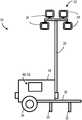
- FIG. 1is a perspective view of an embodiment of a light tower that incorporates light emitting diodes (LEDs).
- LEDslight emitting diodes
- FIG. 2is a schematic view of a generator assembly and associated control system of the LED light tower of FIG. 1 .
- FIG. 1illustrates a perspective view of an embodiment of a light tower 10 .
- the light tower 10includes a light source 20 .
- the light source 20is defined by a plurality of light emitting diodes (LEDs). More specifically, the light source 20 includes a plurality of LED matrices 24 , each of which is defined by a plurality of LEDs that are configured to emit light.
- the LEDs incorporated into LED matrices for light towersgenerally include high intensity LEDs.
- the light source 20includes four LED matrices 24 . However, in other embodiments, the light source 20 can include any number of LED matrices 24 .
- the light source 20is coupled to a support post 26 . More specifically, the light source 20 is coupled at (or near) a first end of the support post 26 . A second, opposite end of the support post 26 is coupled to an enclosure 28 .
- the support post 26can be an adjustable support. For example, the support post 26 can telescope to different lengths to position the light source 20 at a desired height above the enclosure 28 . In other embodiments, the support post 26 can be extendable and retractable to allow for selective positioning and adjustment of the light source 20 .
- the support post 26can also be movably coupled to the enclosure 28 . For example, the support post 26 can pivot relative to the enclosure 28 from the deployed position (shown in FIG. 1 ) to a retracted position (not shown). The support post 26 can be transitioned to the retracted (or stored) position during repositioning or storage of the light tower 10 . In other embodiments, the support post 26 can be coupled to (or movably coupled to) a frame 30 .
- the enclosure 28is mounted to the frame 30 , such that the frame 30 carries the enclosure 28 .
- the frame 30can include a plurality of supports 32 and a plurality of wheels 34 .
- the wheels 34facilitate movement of the light tower 10 (e.g., the light tower can be towed to a desired position, etc.).
- the supports 32provide structural support to the frame 30 and associated components in the deployed position (e.g., during light tower 10 operation).
- the enclosure 28houses a generator assembly 40 and a control system 60 .
- the generator assembly 40includes a prime mover 42 , an alternator 44 , and a rectifier 46 .
- the prime mover 42is a diesel engine 42 .
- the prime mover 42can be any suitable motor or engine (e.g., an electric motor, a natural gas motor, etc.).
- the prime mover 42has a rotatable output that is operably connected to the alternator 44 .
- the alternator 44is a claw-pole rotor generator, and is also referred to as a Lundell generator.
- the alternator 44can include a rotor (such as a claw-pole rotor, not shown), a stator (or a stator assembly, not shown), and an armature 48 .
- the alternator 44is driven by the prime mover 42 .
- the alternator 44can be driven by a belt (or a belt transmission, not shown).
- the alternator 44can be directly driven by the prime mover 42 (e.g., by a drive shaft, etc.).
- the rectifier 46is operably connected to the alternator 44 .
- the alternator 44generates AC electrical energy, which is received by the rectifier 46 .
- the rectifier 46converts the AC electrical energy to direct current (DC) electrical energy to power the light source 20 .
- DCdirect current
- An electricity distribution network 50communicates the direct current electrical energy from the generator assembly 40 to the light source 20 .
- the electricity distribution network 50includes an electrical connection 52 , such as a power cable, cord, wiring, or other conductor suitable for supplying (or transmitting) electrical energy from the generator assembly 40 to the light source 20 .
- the electrical connection 52is divided into a plurality of connections 52 , with each connection 52 associated with a separate LED matrix 24 . As illustrated in FIG. 2 , the example of the light source 20 includes four LED matrices 24 a - d .
- the electrical connection 52includes a first electrical connection 52 a coupled to a first LED matrix 24 a , a second electrical connection 52 b coupled to a second LED matrix 24 b , a third electrical connection 52 c coupled to a third LED matrix 24 c , and a fourth electrical connection 52 d coupled to a fourth LED matrix 24 d .
- the electrical connections 52 a - dsupply DC electrical energy from the generator assembly 40 , and more specifically the rectifier 46 , to each associated LED matrix 24 a - d .
- the electrical connection 52can be divided into any suitable number of connections 52 based on the number of LED matrices 24 .
- the electrical connection 52can be a single connection 52 , or divided into two, three, five, or six or more connections 52 based on the number of LED matrices 24 .
- an N number of LED matrices 24can include an N number of electrical connections 52 , with each electrical connection 52 associated with one LED matrix 24 .
- the control system 60(or current control system 60 ) is operably connected to the generator assembly 40 and the light source 20 .
- the control system 60regulates the alternator 44 of the generator assembly 40 to limit the maximum amount of DC electrical energy provided to the light source.
- the control system 60can be tuned to provide an acceptable current to the LED matrices 24 without exceeding a maximum acceptable current rating, which would reduce LED life expectancy.
- the control system 60includes a regulator 62 .
- the regulator 62is operably coupled to the armature 48 by a first connection 64 .
- the regulator 62is also operably coupled to a battery 66 by a second connection 68 .
- the regulator 62regulates the voltage produced by the alternator.
- the regulator 62is also in communication with at least one current sensor 70 .
- a current sensor 70is associated with each electrical connection 52 to detect the electrical current being supplied by the alternator 44 to each associated LED matrix 24 , which determines the overall load on the alternator.
- a first current sensor 70 ais positioned in the first electrical connection 52 a downstream of the generator assembly 40 and upstream of the first LED matrix 24 a .
- a second current sensor 70 bis positioned in the second electrical connection 52 b downstream of the generator assembly 40 and upstream of the second LED matrix 24 b .
- a third current sensor 70 cis positioned in the third electrical connection 52 c downstream of the generator assembly 40 and upstream of the third LED matrix 24 c .
- a fourth current sensor 70 dis positioned in the fourth electrical connection 52 d downstream of the generator assembly 40 and upstream of the fourth LED matrix 24 d .
- each electrical connection 52includes a respective current sensor 70 . Accordingly, embodiments with N number of electrical connections 52 can include N number of current sensors 70 , with each electrical connection 52 including a current sensor 70 .
- Each current sensor 70is in communication with the regulator 62 by a current communication link 74 .
- the first current sensor 70 ais in communication with the regulator 62 by a first current communication link 74 a .
- the second current sensor 70 bis in communication with the regulator 62 by a second current communication link 74 b
- the third current sensor 70 cis in communication with the regulator 62 by a third current communication link 74 c
- the fourth current sensor 70 dis in communication with the regulator 62 by a fourth current communication link 74 d .
- Each current sensor 70is generally in communication with the regulator 62 by a separate current communication link 74 . Accordingly, embodiments with N number of current sensors 70 will include N number of current communication links 74 , with each current sensor 70 being in communication with the regulator 62 by a separate current communication link 74 .
- the regulator 62is also configured to measure voltage of the DC electrical energy in the electrical connection 52 .
- a voltage communication link 78connects the regulator 62 to the electrical connection 52 .
- the voltage communication link 78is connected to the electrical connection 52 downstream of the generator assembly 40 , and upstream of the light source 20 .
- the voltage communication link 78is connected to the electrical connection 52 downstream of the rectifier 46 , and upstream of the current sensors 70 .
- the voltage communication link 78can connected to the electrical connection 52 at any suitable location or position downstream of the generator assembly 40 .
- the prime mover 42powers the alternator 44 to generate the alternating current (AC) electrical energy.
- the rectifier 46receives the AC electrical energy and converts it to DC electrical energy.
- the DC electrical energyis transmitted to each LED matrix 24 through the electrical connection 52 .
- the LED matrices 24require the DC electrical energy to be supplied at or below a maximum current level.
- the regulator 62measures the current and voltage of the DC electrical energy in the electrical connection 52 and responsively controls the alternator 44 . More specifically, the regulator 62 receives current information associated with the DC electrical energy in the electrical connection 52 from each current sensor 70 .
- Each current sensor 70is measuring the current being delivered to the LED matrices 24 , which is collectively the alternator load.
- the regulator 62receives the current information, and can responsively control the alternator 44 to achieve an appropriate current level (the “target current”).
- the regulator 62implements a control loop to modulate an excitation current to rotating field windings of the alternator 44 .
- the regulator 62receives voltage information associated with the DC electrical energy in the electrical connection 52 through the voltage communication link 78 .
- the regulator 62modulates the excitation current to the rotating field windings. For example, the regulator 62 can increase or decrease modulation of the excitation current to achieve the necessary target current.
- the regulator 62continues to receive the current information from each current sensor 70 , and the voltage information, and responsively modulates the excitation current to achieve and/or maintain the target current.
- the target constant currentcan be any suitable pre-determined current level at or below a maximum acceptable current at which the LED matrices 24 can operate without being damaged.
- the maximum acceptable currentcan be any suitable current that does not exceed a maximum current rating for the LED matrices 24 . Exceeding the maximum current rating for the LED matrices 24 can undesirably reduce LED life expectancy.
- the generator assembly 40 and associated control system 60advantageously eliminate the need for an external power conditioning unit that is common for LED matrices by controlling the alternator 44 to a constant current.
- the control system 60advantageously allows for the use of a Lundell generator as the alternator 44 . This is a more readily available and lower cost alternative than a customized alternator to provide limited DC electrical energy to one or more LED matrices.
Landscapes
- Engineering & Computer Science (AREA)
- General Engineering & Computer Science (AREA)
- Power Engineering (AREA)
- Microelectronics & Electronic Packaging (AREA)
- Life Sciences & Earth Sciences (AREA)
- Sustainable Development (AREA)
- Sustainable Energy (AREA)
- Control Of Eletrric Generators (AREA)
Abstract
Description
Claims (14)
Priority Applications (4)
| Application Number | Priority Date | Filing Date | Title |
|---|---|---|---|
| US15/947,440US10856381B2 (en) | 2018-04-06 | 2018-04-06 | Power delivery system for a light tower |
| CA3094109ACA3094109A1 (en) | 2018-04-06 | 2019-03-26 | Power delivery system for a light tower |
| EP19716273.8AEP3777483B1 (en) | 2018-04-06 | 2019-03-26 | Power delivery system for a light tower |
| PCT/US2019/024122WO2019195034A1 (en) | 2018-04-06 | 2019-03-26 | Power delivery system for a light tower |
Applications Claiming Priority (1)
| Application Number | Priority Date | Filing Date | Title |
|---|---|---|---|
| US15/947,440US10856381B2 (en) | 2018-04-06 | 2018-04-06 | Power delivery system for a light tower |
Publications (2)
| Publication Number | Publication Date |
|---|---|
| US20190309915A1 US20190309915A1 (en) | 2019-10-10 |
| US10856381B2true US10856381B2 (en) | 2020-12-01 |
Family
ID=66092406
Family Applications (1)
| Application Number | Title | Priority Date | Filing Date |
|---|---|---|---|
| US15/947,440Active2038-08-24US10856381B2 (en) | 2018-04-06 | 2018-04-06 | Power delivery system for a light tower |
Country Status (4)
| Country | Link |
|---|---|
| US (1) | US10856381B2 (en) |
| EP (1) | EP3777483B1 (en) |
| CA (1) | CA3094109A1 (en) |
| WO (1) | WO2019195034A1 (en) |
Families Citing this family (3)
| Publication number | Priority date | Publication date | Assignee | Title |
|---|---|---|---|---|
| ES2849798A1 (en)* | 2020-02-20 | 2021-08-23 | Himoinsa S L | Lighting system supplied with liquefied petroleum gas (Machine-translation by Google Translate, not legally binding) |
| US11913611B2 (en) | 2021-10-15 | 2024-02-27 | Briggs & Stratton, Llc | Hybrid light tower |
| US11959616B2 (en) | 2021-10-15 | 2024-04-16 | Briggs & Stratton, Llc | Battery powered light tower |
Citations (5)
| Publication number | Priority date | Publication date | Assignee | Title |
|---|---|---|---|---|
| US5294879A (en) | 1991-11-01 | 1994-03-15 | Basler Electric Company | Microprocessor-controlled regulator |
| US5808450A (en)* | 1996-08-15 | 1998-09-15 | Marathon Electric Manufacturing Corporation | Special alternator assembly with an inherent ballast impedance characteristic for lighting systems |
| AU2011100774A4 (en) | 2010-07-22 | 2011-08-04 | Istvan Torok | A portable lighting tower |
| AU2013100095A4 (en) | 2013-01-30 | 2013-03-07 | Southern Cross Mining Services Pty Ltd | Lighting tower |
| US20180266637A1 (en)* | 2015-08-24 | 2018-09-20 | Cleantek Industries Inc. | Direct current hybrid lighting and energy management systems and methods |
Family Cites Families (1)
| Publication number | Priority date | Publication date | Assignee | Title |
|---|---|---|---|---|
| CN202206341U (en) | 2011-08-16 | 2012-04-25 | 中国地质科学院地球物理地球化学勘查研究所 | High-voltage excitation constant-current power supply system |
- 2018
- 2018-04-06USUS15/947,440patent/US10856381B2/enactiveActive
- 2019
- 2019-03-26WOPCT/US2019/024122patent/WO2019195034A1/ennot_activeCeased
- 2019-03-26EPEP19716273.8Apatent/EP3777483B1/enactiveActive
- 2019-03-26CACA3094109Apatent/CA3094109A1/enactivePending
Patent Citations (5)
| Publication number | Priority date | Publication date | Assignee | Title |
|---|---|---|---|---|
| US5294879A (en) | 1991-11-01 | 1994-03-15 | Basler Electric Company | Microprocessor-controlled regulator |
| US5808450A (en)* | 1996-08-15 | 1998-09-15 | Marathon Electric Manufacturing Corporation | Special alternator assembly with an inherent ballast impedance characteristic for lighting systems |
| AU2011100774A4 (en) | 2010-07-22 | 2011-08-04 | Istvan Torok | A portable lighting tower |
| AU2013100095A4 (en) | 2013-01-30 | 2013-03-07 | Southern Cross Mining Services Pty Ltd | Lighting tower |
| US20180266637A1 (en)* | 2015-08-24 | 2018-09-20 | Cleantek Industries Inc. | Direct current hybrid lighting and energy management systems and methods |
Non-Patent Citations (3)
| Title |
|---|
| International Preliminary Report on Patentability dated Oct. 15, 2020 for corresponding International Application No. PCT/2019/024122 (9 pages). |
| International Search Report dated May 27, 2019 for corresponding International Application No. PCT/US2019/024122 (9 pages). |
| International Written Opinion of the International Search Authority dated May 27, 2019 for corresponding International Application No. PCT/US2019/024122 (9 pages). |
Also Published As
| Publication number | Publication date |
|---|---|
| CA3094109A1 (en) | 2019-10-10 |
| WO2019195034A1 (en) | 2019-10-10 |
| US20190309915A1 (en) | 2019-10-10 |
| EP3777483C0 (en) | 2023-06-07 |
| EP3777483A1 (en) | 2021-02-17 |
| EP3777483B1 (en) | 2023-06-07 |
Similar Documents
| Publication | Publication Date | Title |
|---|---|---|
| US10856381B2 (en) | Power delivery system for a light tower | |
| ES2225376T3 (en) | PROCEDURE TO OPERATE A WIND ENERGY INSTALLATION, AS WELL AS A WIND ENERGY INSTALLATION. | |
| US8653679B2 (en) | Portable power supply having both inverter power supply and traditional power supply receptacles | |
| US8237416B2 (en) | More electric engine with regulated permanent magnet machines | |
| EP1092090B1 (en) | Dc local grid for windfarm | |
| US20100283242A1 (en) | High Voltage Start of an Engine from a Low Voltage Battery | |
| US11420771B2 (en) | System and method for providing electrical power to a tethered aerial vehicle | |
| US20110169328A1 (en) | Generator for gas turbine engine having main dc bus accessory ac bus | |
| US20130334889A1 (en) | Control arrangement and method for regulating the ouput current of a dc source power converter connected to a multi-source dc system | |
| US6876096B2 (en) | Electrical power generation unit | |
| US10523146B2 (en) | Off-grid power generating apparatus and frequency and voltage control method thereof | |
| RU73260U1 (en) | MOBILE UNIVERSAL WELDING UNIT TRANSPORT "MUSAT" | |
| ES2826859T3 (en) | Power supply system | |
| US6590298B1 (en) | Electrical power generation unit for welding including electromechanical feedback mode regulation | |
| ES2575093T3 (en) | Test device and procedure to check a first and / or a second electric machine | |
| EP3361834B1 (en) | Extra-low voltage outdoor lighting system, luminaire, power supply and assembly and method of providing outdoor illumination | |
| US8350530B2 (en) | Aircraft battery charging system having two voltage regulators | |
| US11382193B1 (en) | Systems and methods related to photovoltaic direct drive lighting systems | |
| US20200059153A1 (en) | Power supply system for ventilation fan | |
| RU158933U1 (en) | AUTONOMOUS WIND-DIESEL-ELECTRIC INSTALLATION | |
| CN222452544U (en) | Tethered unmanned aerial vehicle lighting system | |
| CN208316608U (en) | Adjusting circuit in automobile dynamo governor | |
| KR20250136343A (en) | Aircraft electrical power system and method for regulating and supplying voltage to power fluctuations of stationary aircraft | |
| WO2023155026A1 (en) | Self-generating electricity generating system | |
| KR20200008457A (en) | Electric vehicle-mounted generator control system and device |
Legal Events
| Date | Code | Title | Description |
|---|---|---|---|
| FEPP | Fee payment procedure | Free format text:ENTITY STATUS SET TO UNDISCOUNTED (ORIGINAL EVENT CODE: BIG.); ENTITY STATUS OF PATENT OWNER: LARGE ENTITY | |
| AS | Assignment | Owner name:CLARK EQUIPMENT COMPANY, NORTH CAROLINA Free format text:ASSIGNMENT OF ASSIGNORS INTEREST;ASSIGNORS:HARKNETT, NICHOLAS;RANKER, ROBERT;SIGNING DATES FROM 20180403 TO 20180405;REEL/FRAME:045482/0670 | |
| STPP | Information on status: patent application and granting procedure in general | Free format text:DOCKETED NEW CASE - READY FOR EXAMINATION | |
| STPP | Information on status: patent application and granting procedure in general | Free format text:NON FINAL ACTION MAILED | |
| AS | Assignment | Owner name:WILMINGTON TRUST, NATIONAL ASSOCIATION, AS COLLATERAL AGENT, MINNESOTA Free format text:PATENT SECURITY AGREEMENT (NOTES);ASSIGNOR:CLARK EQUIPMENT COMPANY;REEL/FRAME:052802/0464 Effective date:20200529 | |
| STPP | Information on status: patent application and granting procedure in general | Free format text:RESPONSE TO NON-FINAL OFFICE ACTION ENTERED AND FORWARDED TO EXAMINER | |
| STCF | Information on status: patent grant | Free format text:PATENTED CASE | |
| AS | Assignment | Owner name:BANK OF AMERICA, N.A., AS ADMINISTRATIVE AGENT, NEW YORK Free format text:SECURITY INTEREST;ASSIGNOR:CLARK EQUIPMENT COMPANY;REEL/FRAME:059841/0543 Effective date:20220420 | |
| AS | Assignment | Owner name:CLARK EQUIPMENT COMPANY, NORTH DAKOTA Free format text:RELEASE BY SECURED PARTY;ASSIGNOR:WILMINGTON TRUST, NATIONAL ASSOCIATION;REEL/FRAME:061365/0517 Effective date:20220624 | |
| AS | Assignment | Owner name:DOOSAN BOBCAT NORTH AMERICA, INC., NORTH CAROLINA Free format text:CHANGE OF NAME;ASSIGNOR:CLARK EQUIPMENT COMPANY;REEL/FRAME:067189/0553 Effective date:20230815 | |
| MAFP | Maintenance fee payment | Free format text:PAYMENT OF MAINTENANCE FEE, 4TH YEAR, LARGE ENTITY (ORIGINAL EVENT CODE: M1551); ENTITY STATUS OF PATENT OWNER: LARGE ENTITY Year of fee payment:4 |