US10853334B2 - Technologies for providing service isolation, scalability, and proactive tenant migration in multi-tenant ecosystems - Google Patents
Technologies for providing service isolation, scalability, and proactive tenant migration in multi-tenant ecosystemsDownload PDFInfo
- Publication number
- US10853334B2 US10853334B2US15/910,899US201815910899AUS10853334B2US 10853334 B2US10853334 B2US 10853334B2US 201815910899 AUS201815910899 AUS 201815910899AUS 10853334 B2US10853334 B2US 10853334B2
- Authority
- US
- United States
- Prior art keywords
- ecosystem
- tenant
- instance
- instances
- trigger
- Prior art date
- Legal status (The legal status is an assumption and is not a legal conclusion. Google has not performed a legal analysis and makes no representation as to the accuracy of the status listed.)
- Active, expires
Links
Images


Classifications
- H—ELECTRICITY
- H04—ELECTRIC COMMUNICATION TECHNIQUE
- H04L—TRANSMISSION OF DIGITAL INFORMATION, e.g. TELEGRAPHIC COMMUNICATION
- H04L41/00—Arrangements for maintenance, administration or management of data switching networks, e.g. of packet switching networks
- H04L41/40—Arrangements for maintenance, administration or management of data switching networks, e.g. of packet switching networks using virtualisation of network functions or resources, e.g. SDN or NFV entities
- G—PHYSICS
- G06—COMPUTING OR CALCULATING; COUNTING
- G06F—ELECTRIC DIGITAL DATA PROCESSING
- G06F16/00—Information retrieval; Database structures therefor; File system structures therefor
- G06F16/20—Information retrieval; Database structures therefor; File system structures therefor of structured data, e.g. relational data
- G06F16/21—Design, administration or maintenance of databases
- G06F16/214—Database migration support
- G—PHYSICS
- G06—COMPUTING OR CALCULATING; COUNTING
- G06F—ELECTRIC DIGITAL DATA PROCESSING
- G06F16/00—Information retrieval; Database structures therefor; File system structures therefor
- G06F16/20—Information retrieval; Database structures therefor; File system structures therefor of structured data, e.g. relational data
- G06F16/27—Replication, distribution or synchronisation of data between databases or within a distributed database system; Distributed database system architectures therefor
- H—ELECTRICITY
- H04—ELECTRIC COMMUNICATION TECHNIQUE
- H04L—TRANSMISSION OF DIGITAL INFORMATION, e.g. TELEGRAPHIC COMMUNICATION
- H04L41/00—Arrangements for maintenance, administration or management of data switching networks, e.g. of packet switching networks
- H04L41/08—Configuration management of networks or network elements
- H04L41/0896—Bandwidth or capacity management, i.e. automatically increasing or decreasing capacities
- H04L41/0897—Bandwidth or capacity management, i.e. automatically increasing or decreasing capacities by horizontal or vertical scaling of resources, or by migrating entities, e.g. virtual resources or entities
- H—ELECTRICITY
- H04—ELECTRIC COMMUNICATION TECHNIQUE
- H04L—TRANSMISSION OF DIGITAL INFORMATION, e.g. TELEGRAPHIC COMMUNICATION
- H04L43/00—Arrangements for monitoring or testing data switching networks
- H04L43/08—Monitoring or testing based on specific metrics, e.g. QoS, energy consumption or environmental parameters
- H04L43/0876—Network utilisation, e.g. volume of load or congestion level
- H—ELECTRICITY
- H04—ELECTRIC COMMUNICATION TECHNIQUE
- H04L—TRANSMISSION OF DIGITAL INFORMATION, e.g. TELEGRAPHIC COMMUNICATION
- H04L43/00—Arrangements for monitoring or testing data switching networks
- H04L43/16—Threshold monitoring
- H—ELECTRICITY
- H04—ELECTRIC COMMUNICATION TECHNIQUE
- H04L—TRANSMISSION OF DIGITAL INFORMATION, e.g. TELEGRAPHIC COMMUNICATION
- H04L43/00—Arrangements for monitoring or testing data switching networks
- H04L43/20—Arrangements for monitoring or testing data switching networks the monitoring system or the monitored elements being virtualised, abstracted or software-defined entities, e.g. SDN or NFV
- H—ELECTRICITY
- H04—ELECTRIC COMMUNICATION TECHNIQUE
- H04L—TRANSMISSION OF DIGITAL INFORMATION, e.g. TELEGRAPHIC COMMUNICATION
- H04L67/00—Network arrangements or protocols for supporting network services or applications
- H04L67/01—Protocols
- H04L67/10—Protocols in which an application is distributed across nodes in the network
- H04L67/1001—Protocols in which an application is distributed across nodes in the network for accessing one among a plurality of replicated servers
- H04L67/1004—Server selection for load balancing
- H04L67/1008—Server selection for load balancing based on parameters of servers, e.g. available memory or workload
- H—ELECTRICITY
- H04—ELECTRIC COMMUNICATION TECHNIQUE
- H04L—TRANSMISSION OF DIGITAL INFORMATION, e.g. TELEGRAPHIC COMMUNICATION
- H04L41/00—Arrangements for maintenance, administration or management of data switching networks, e.g. of packet switching networks
- H04L41/08—Configuration management of networks or network elements
- H04L41/0803—Configuration setting
- H04L41/0813—Configuration setting characterised by the conditions triggering a change of settings
- H04L41/0816—Configuration setting characterised by the conditions triggering a change of settings the condition being an adaptation, e.g. in response to network events
- H—ELECTRICITY
- H04—ELECTRIC COMMUNICATION TECHNIQUE
- H04L—TRANSMISSION OF DIGITAL INFORMATION, e.g. TELEGRAPHIC COMMUNICATION
- H04L41/00—Arrangements for maintenance, administration or management of data switching networks, e.g. of packet switching networks
- H04L41/50—Network service management, e.g. ensuring proper service fulfilment according to agreements
- H04L41/5003—Managing SLA; Interaction between SLA and QoS
- H04L41/5009—Determining service level performance parameters or violations of service level contracts, e.g. violations of agreed response time or mean time between failures [MTBF]
Definitions
- One or more implementationsrelate generally to database systems, and in particular to systems and methods for performance monitoring and tenant migration in multi-tenant and/or cloud computing ecosystems.
- customer organizationsmay share database resources in one logical database.
- the databases themselvesare typically shared, and each tenant is typically associated with an organization identifier (org ID) column or field that may be used to identify rows or records belonging to each tenant.
- org IDorganization identifier
- Each tenantmay provide their own custom data, which may include defining custom objects and custom fields, as well as designating one or more custom fields to act as custom index fields.
- Users of a multi-tenant database systeme.g., a tenant/organization (org) or developers associated with the tenant
- the applications/platformsmay obtain data from the associated tenant space to render/display visual representations of relevant tenant data.
- the multi-tenant database systemsmay include various servers to service requests and provide data to the user/tenants.
- the various servers and data storage devices of the multi-tenant systemmay be implemented as a tenant ecosystem or environment that may include multiple tiers or subsystems, which provide different services to the various tenants/orgs.
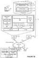
- FIG. 1Ashows a block diagram of an example environment in which an on-demand database service can be used according to some implementations.
- FIG. 1Bshows a block diagram of example implementations of elements of FIG. 1A and example interconnections between these elements according to some implementations.
- FIG. 2Aillustrates the components of the cloud computing service according to some embodiments.
- FIG. 2Bshows an example arrangement in which various embodiments discussed herein may be practiced.
- FIG. 2Cshows an example arrangement in which various embodiments discussed herein may be practiced.
- FIG. 3Ashows an example auto-scaling configuration process, in accordance with various embodiments.
- FIG. 3Bshows a proactive tenant monitoring and migration configuration process, in accordance with various embodiments.
- FIG. 4shows an example spin-off and migration process in accordance with various embodiments.
- FIG. 5shows another example spin-off and migration process in accordance with various embodiments.
- Embodiments discussed hereinprovide a framework for scaling ecosystems/environments based on input load characteristics, proactive monitoring of tenant migration, and providing service isolation in multi-tenant environments.
- a set of performance metrics of an ecosystem instancemay be identified.
- the ecosystem instancemay comprise a set of service tiers to provide services for tenants of a multi-tenant system.
- one or more other ecosystem instancesmay be generated based on the performance metrics.
- Each of the one or more other ecosystem instancesmay include individual sets of service tiers that are isolated from one another and from the service tiers of the ecosystem instance from which the other ecosystem instances were spun off.
- one or more tenantsmay be migrated from the ecosystem instance to another ecosystem instance of the one or more other ecosystem instances, and a set of service tiers of the other ecosystem instance may provide services to the migrated tenants.
- Other embodimentsmay be described and/or claimed.
- various indicatorsmay be defined for identification of an input load. Different thresholds, such as a low and high warning thresholds, may be defined based on the indicators. If the thresholds are breached (or reached), an auto-scale process may be triggered to scale up or scale down the nodes in a given subsystem/tier. This mechanism may co-exist with the KPI and KCI based auto-scale processes. Auto-scaling of ecosystems based on input load indicators may help proactively avoid service degradation or non-deterministic behavior resulting from KPIs and/or KCIs based auto-scaling approaches.
- the auto-scale processesmay be triggered when the low warning threshold is reached.
- New ecosystem instancesmay be generated when the high warning threshold is reached, and tenants may be proactively migrated out to the new ecosystem instances.
- new ecosystem instancesmay be generated when the low warning threshold is reached, and tenants may be proactively migrated out to the new ecosystem instances when the high warning threshold is reached.
- tenant-level parameters that influences the KPIs and KCIsmay be monitored and used as a basis for migrating tenants to different ecosystem instances.
- tenant sizesmay be determined from the tenant-level parameters discussed previously, and various warning thresholds may be defined that, when reached, may re-categorize a given tenant into the proper tenant-size, or cause the tenant to be migrated to a new ecosystem instance.
- Monitoring tenant-level attributes and re-categorizing tenant into right sized-based-categorymay help proactive capacity planning and proactive migration without causing (or reduce) service impacts to other tenants.
- Categorizing tenants based on size attributes and/or resource consumption, and defining thresholds on the maximum number of tenants of a specific size that can reside in an ecosystemmay help avoid situations where tenants are reactively migrated to another ecosystem.
- individual ecosystem instancesmay have a maximum number of tenants and an ecosystem size based on available and/or maximum resources. The maximum number of tenants and sizes may be different for different ecosystem instances. Additionally, each ecosystem instance may have different thresholds trigger the auto-scale, ecosystem spin-off, and proactive tenant migration processes discussed previously. Defining a maximum number of tenants per ecosystem and creating additional ecosystems (in separate availability zones) may help isolate tenants into different ecosystems and localize any service degradation/outages. In embodiments, once tenant migration is completed, appropriate configuration changes to the global load balancers may take effect so that traffic for the migrated tenants is redirect to the new ecosystem instance in which a tenant resides.
- embodiments discussed hereinmay help avoid scaling-related issues with regard to infrastructure deployments and/or resource allocation. Additionally, embodiments may allow for faster and/or optimal tenant integration, better/optimal handling of tenants whose size increases over time, as well as providing lower operating and support costs. Furthermore, embodiments herein may reduce tenant performance/capacity/availability issues resulting in increased tenant satisfaction and trust.
- Some implementations described and referenced hereinare directed to systems, apparatus, computer-implemented methods and computer-readable storage media for identifying articles helpful in resolving user queries.
- the term “tenant”may include a group of users who share common access with specific privileges to a software instance.
- a multi-tenant architecturesuch as those discussed herein, may provide a tenant with a dedicated share of a software instance typically including one or more of tenant specific data, user management, tenant-specific functionality, configuration, customizations, non-functional properties, associated applications, etc. Multi-tenancy contrasts with multi-instance architectures, where separate software instances operate on behalf of different tenants.
- the term an “instance”may refer to a concrete occurrence of an object, which may occur, for example, during execution of program code, and the terms “instantiate”, “instantiation”, and the like may refer to the creation of an instance.
- the terms “resource,” “computing resource,” “hardware resource,” etc.may refer to a physical or virtual device, a physical or virtual component within a computing environment, and/or physical or virtual component within a particular device, such as computer devices, mechanical devices, memory space, processor/CPU time and/or processor/CPU usage, processor and accelerator loads, hardware time or usage, electrical power, input/output operations, ports or network sockets, channel/link allocation, throughput, memory usage, storage, network, database and applications, and/or the like.
- the term “network resource”may refer to computing resources that are accessible by computer devices via a communications network.
- system resourcesmay refer to any kind of shared entities to provide services, and may include computing and/or network resources.
- System resourcesmay be considered as a set of coherent functions, network data objects or services, accessible through a server where such system resources reside on a single host or multiple hosts and are clearly identifiable.
- a “virtualized resource”may refer to compute, storage, and/or network resources provided by virtualization infrastructure to an application, such as a mobile edge application.
- the term “resource”may refer to the particular resource being accessed or an address or other means of accessing the resource.
- the users described hereinare users (or “members”) of an interactive online “enterprise social network,” also referred to herein as an “enterprise social networking system,” an “enterprise collaborative network,” or more simply as an “enterprise network.”
- entity social networkalso referred to herein as an “enterprise social networking system,” an “enterprise collaborative network,” or more simply as an “enterprise network.”
- Such online enterprise networksare increasingly becoming a common way to facilitate communication among people, any of whom can be recognized as enterprise users.
- Chatter®provided by salesforce.com, inc. of San Francisco, Calif.
- salesforce.com, inc.is a provider of enterprise social networking services, customer relationship management (CRM) services and other database management services, any of which can be accessed and used in conjunction with the techniques disclosed herein in some implementations.
- CRMcustomer relationship management
- FIG. 1Ashows a block diagram of an example of an environment 10 in which an on-demand database service can be used in accordance with some implementations.
- the environment 10includes user systems 12 , a network 14 , a database system 16 (also referred to herein as a “cloud-based system”), a processor system 17 , an application platform 18 , a network interface 20 , tenant database 22 for storing tenant data 23 , system database 24 for storing system data 25 , program code 26 for implementing various functions of the system 16 , and process space 28 for executing database system processes and tenant-specific processes, such as running applications as part of an application hosting service.
- environment 10may not have all of these components or systems, or may have other components or systems instead of, or in addition to, those listed above.
- the tenant data storage 22 , the system data storage 24 , and/or some other data storemay include Extract-Load-Transform (ELT) data or Extract-Transform-Load (ETL) data, which may be raw data extracted from various sources and normalized (e.g., indexed, partitioned, augmented, canonicalized, etc.) for analysis and other transformations.
- ELTExtract-Load-Transform
- ETLExtract-Transform-Load
- the raw datamay be loaded into the tenant data storage 22 , the system data storage 24 , and/or some other data store (not shown) and stored as key-value pairs, which may allow the data to be stored in a mostly native form without requiring substantial normalization or formatting.
- the environment 10is an environment in which an on-demand database service exists.
- An on-demand database servicesuch as that which can be implemented using the system 16 , is a service that is made available to users outside of the enterprise(s) that own, maintain or provide access to the system 16 . As described above, such users generally do not need to be concerned with building or maintaining the system 16 . Instead, resources provided by the system 16 may be available for such users' use when the users need services provided by the system 16 ; that is, on the demand of the users.
- Some on-demand database servicescan store information from one or more tenants into tables of a common database image to form a multi-tenant database system (MTS).
- MTSmulti-tenant database system
- multi-tenant database systemcan refer to those systems in which various elements of hardware and software of a database system may be shared by one or more customers or tenants. For example, a given application server may simultaneously process requests for a great number of customers, and a given database table may store rows of data such as feed items for a potentially much greater number of customers.
- a database imagecan include one or more database objects.
- RDBMSrelational database management system
- a relational database management system (RDBMS) or the equivalentcan execute storage and retrieval of information against the database object(s).
- Application platform 18can be a framework that allows the applications of system 16 to execute, such as the hardware or software infrastructure of the system 16 .
- the application platform 18enables the creation, management and execution of one or more applications developed by the provider of the on-demand database service, users accessing the on-demand database service via user systems 12 , or third party application developers accessing the on-demand database service via user systems 12 .
- the system 16implements a web-based customer relationship management (CRM) system.
- the system 16includes application servers configured to implement and execute CRM software applications as well as provide related data, code, forms, renderable web pages and documents and other information to and from user systems 12 and to store to, and retrieve from, a database system related data, objects, and web page content.
- CRMcustomer relationship management
- data for multiple tenantsmay be stored in the same physical database object in tenant database 22 .
- tenant datais arranged in the storage medium(s) of tenant database 22 so that data of one tenant is kept logically separate from that of other tenants so that one tenant does not have access to another tenant's data, unless such data is expressly shared.
- the system 16also implements applications other than, or in addition to, a CRM application.
- the system 16can provide tenant access to multiple hosted (standard and custom) applications, including a CRM application.
- User (or third party developer) applicationswhich may or may not include CRM, may be supported by the application platform 18 .
- the application platform 18manages the creation and storage of the applications into one or more database objects and the execution of the applications in one or more virtual machines in the process space of the system 16 .
- the applications of the application platform 18may be developed with server-side programming languages, such as PHP, Java and/or Java Server Pages (JSP), Node.js, ASP.NET, and/or any other like technology that renders HTML.
- the applicationsmay be built using a platform-specific and/or proprietary development tool and/or programming languages, such as Salesforce® Apex and/or the like.
- each system 16is configured to provide web pages, forms, applications, data and media content to user (client) systems 12 to support the access by user systems 12 as tenants of system 16 .
- system 16provides security mechanisms to keep each tenant's data separate unless the data is shared.
- MTSMobility Management Entity
- theymay be located in close proximity to one another (for example, in a server farm located in a single building or campus), or they may be distributed at locations remote from one another (for example, one or more servers located in city A and one or more servers located in city B).
- each MTScould include one or more logically or physically connected servers distributed locally or across one or more geographic locations.
- serveris meant to refer to a computing device or system, including processing hardware and process space(s), an associated storage medium such as a memory device or database, and, in some instances, a database application (for example, OODBMS or RDBMS) as is well known in the art. It should also be understood that “server system” and “server” are often used interchangeably herein.
- database objects described hereincan be implemented as part of a single database, a distributed database, a collection of distributed databases, a database with redundant online or offline backups or other redundancies, etc., and can include a distributed database or storage network and associated processing intelligence.
- the network 14can be or include any network or combination of networks of systems or devices that communicate with one another.
- the network 14can be or include any one or any combination of a local area network (LAN), a wireless LAN (WLAN), wide area network (WAN), telephone network, wireless network, cellular network, point-to-point network, star network, token ring network, hub network, or other appropriate configuration including proprietary and/or enterprise networks, or combinations thereof.
- the network 14can include a Transfer Control Protocol and Internet Protocol (TCP/IP) network, such as the global internetwork of networks often referred to as the “Internet” (with a capital “I”).
- TCP/IPTransfer Control Protocol and Internet Protocol
- the Internetwill be used in many of the examples herein.
- the network 14may comprise one or more network elements, each of which may include one or more processors, communications systems (e.g., including network interface controllers, one or more transmitters/receivers connected to one or more antennas, etc.), and computer readable media.
- network elementsmay include wireless APs (WAPs), a home/business server (with or without radio frequency (RF) communications circuitry), routers, switches, hubs, radio beacons, (macro or small-cell) base stations, servers (e.g., stand-alone, rack-mounted, blade, etc.), and/or any other like devices/systems.
- WAPswireless APs
- RFradio frequency
- Connection to the network 14may be via a wired or a wireless connection using one or more of the various communication protocols discussed infra.
- a wired or wireless communication protocolmay refer to a set of standardized rules or instructions implemented by a communication device/system to communicate with other devices, including instructions for packetizing/depacketizing data, modulating/demodulating signals, implementation of protocols stacks, and the like.
- Connection to the network 14may require that the various devices and network elements execute software routines which enable, for example, the seven layers of the open systems interconnection (OSI) model of computer networking or equivalent in a wireless network.
- OSIopen systems interconnection
- the user systems 12can communicate with system 16 using TCP/IP and, at a higher network level, other common Internet protocols to communicate, such as Hypertext Transfer Protocol (HTTP), File Transfer Protocol (FTP), Andrew File System (AFS), Wireless Application Protocol (WAP), Session Initiation Protocol (SIP) with Real-Time Transport Protocol (RTP or Secure RTP (SRTP), Web-based secure shell (SSH), Extensible Messaging and Presence Protocol (XMPP), WebSocket protocol, etc.
- HTTPHypertext Transfer Protocol
- FTPFile Transfer Protocol
- AFSAndrew File System
- WAPWireless Application Protocol
- RTPReal-Time Transport Protocol
- SRTPReal-Time Transport Protocol
- SSHWeb-based secure shell
- XMPPExtensible Messaging and Presence Protocol
- each user system 12may send and receive HTTP messages where a header of each message includes various operating parameters and the body of the such messages may include HTML, Extensible Markup Language (XML), Java Script Object Notion (JSON), Cascading Stylesheets (CSS), JavaServer Pages (JSP), MessagePackTM, Apache® Thrift, Abstract Syntax Notation One (ASN.1), Google® Protocol Buffers (protobuf), database objects, or some other like object(s)/document(s).
- Such an HTTP servercan be implemented as the sole network interface 20 between the system 16 and the network 14 , but other techniques can be used in addition to or instead of these techniques.
- the network interface 20 between the system 16 and the network 14includes load sharing functionality, such as round-robin HTTP request distributors to balance loads and distribute incoming HTTP requests evenly over a number of servers.
- load sharing functionalitysuch as round-robin HTTP request distributors to balance loads and distribute incoming HTTP requests evenly over a number of servers.
- each of the serverscan have access to the MTS data; however, other alternative configurations may be used instead.
- the user systems 12can be implemented as any computing device(s) or other data processing apparatus or systems usable by users to access the database system 16 .
- any of user systems 12can be a desktop computer, a work station, a laptop computer, a tablet computer, a handheld computing device (e.g., Personal Data Assistants (PDAs), pagers, portable media player, etc.), a mobile cellular phone (for example, a “smartphone”), or any other WiFi-enabled device, WAP-enabled device, or other computing device capable of interfacing directly or indirectly to the Internet or other network (e.g., network 14 ).
- PDAsPersonal Data Assistants
- WAP-enabled deviceWireless Fidelity
- the terms “user system”, “computing device”, “computer system”, or the likemay be used interchangeably herein with one another and with the term “computer.”
- each user system 12typically executes an HTTP client, for example, a web browsing (or simply “browsing”) program, such as a web browser based on the WebKit platform, Microsoft's Internet Explorer browser, Apple's Safari, Google's Chrome, Opera's browser, or Mozilla's Firefox browser, and/or the like, to execute and render web applications allowing a user (for example, a subscriber of on-demand services provided by the system 16 ) of the user system 12 to access, process and view information, pages, interfaces, and applications available to it from the system 16 over the network 14 .
- a web browsingor simply “browsing” program, such as a web browser based on the WebKit platform, Microsoft's Internet Explorer browser, Apple's Safari, Google's Chrome, Opera's browser, or Mozilla's Firefox browser, and/or the like
- each user system 12may operate a user (or third party) application designed to interact with applications of the application platform 18 allowing a user (for example, a subscriber of on-demand services provided by the system 16 ) of the user system 12 to access, process and view information, pages and applications available to it from the system 16 over the network 14 .
- a userfor example, a subscriber of on-demand services provided by the system 16
- an owner/operator of database system 16may have pre-built the web or user applications for use by clients, customers, and/or agents of a tenant organization (org) to access a tenant space or enterprise social network of that tenant org.
- developers associated with a tenant orgmay build custom application(s) for interacting with the tenant data.
- the user (or third party) application(s)may be native application(s) (e.g., executed and rendered in an application container) or hybrid application(s) (e.g., web applications being executed/rendered in an application container or skeleton).
- the user (or third party) application(s)may be platform-specific, or developed to operate on a particular type of user system 12 or a particular (hardware and/or software) configuration of a user system 12 .
- the term “platform-specific”may refer to the platform implemented by the user system 12 , the platform implemented by the database system 16 , and/or a platform of a third party system.
- the user systems 12may implement web, user, or third party applications to request and obtain data from database system 16 , and render graphical user interfaces (GUIs) in an application container or browser.
- GUIsgraphical user interfaces
- the GUIsmay include a data analytics GUI, such as Salesforce® WaveTM dashboard, which may provide visual representations of data residing in an enterprise cloud or in an on-demand services environment (e.g., a tenant space within database system 16 ).
- the GUIsmay include one or more components (e.g., graphical control elements (GCEs), tabs, reports, dashboards, widgets, pages, etc.).
- GCEsgraphical control elements
- Examples of such componentsmay include audio/video calling components, messaging components (e.g., chat, instant messaging, short message service (SMS)/multimedia messaging service (MMS) messaging, emailing, etc.), and visualization components.
- the visualization componentsmay enable a user of a user system 12 to select visualization parameters (also referred to as “lens parameters” or “filters”) for displaying data from one or more datasets.
- a datasetmay be a specific view or transformation of data from one or more data sources (e.g., a tenant space of database 22 , etc.).
- the visualization parametersmay include, for example, a selection of data or data type to display from one or more datasets; a particular graph, chart, or map in which to view the selected data; color schemes for the graphs/charts/maps; a position or orientation of the graphs/charts/maps within a particular GUI, etc.
- the graphs/charts/maps to be displayedmay be referred to as a “lens” or a “dashboard”.
- a lensmay be a particular view of data from one or more datasets
- a dashboardmay be a collection of lenses.
- a GUImay display lenses, dashboards, and/or control panels to alter or rearrange the lenses/dashboards.
- the various application(s) discussed hereinmay also enable the user system 12 to provide authentication credentials (e.g., user identifier (user id), password, personal identification number (PIN), digital certificates, etc.) to the database system 16 so that the database system 16 may authenticate the identity of a user of the user system 12 .
- authentication credentialse.g., user identifier (user id), password, personal identification number (PIN), digital certificates, etc.
- the web, user, or third party application(s) discussed hereinmay be a software, program code, logic modules, application packages, etc. that are built using website development tools and/or programming languages, such as HTML, CSS, JavaScript, JQuery, and the like; and/or using platform-specific development tools and/or programming languages (e.g., Salesforce® Apex, Salesforce® Visualforce®, Salesforce® Lightning®, Salesforce® WaveTM Dashboard Designer, Salesforce® Force.com® IDE, Android® StudioTM integrated development environment (IDE), Apple® iOS® software development kit (SDK), etc.).
- website development tools and/or programming languagessuch as HTML, CSS, JavaScript, JQuery, and the like
- platform-specific development tools and/or programming languagese.g., Salesforce® Apex, Salesforce® Visualforce®, Salesforce® Lightning®, Salesforce® WaveTM Dashboard Designer, Salesforce® Force.com® IDE, Android® StudioTM integrated development environment (IDE), Apple® iOS® software development kit (SDK), etc.
- Such applicationsmay utilize a suitable querying language to query and store information in an associated tenant space, such as Structure Query Language (SQL), object query language (OQL), Salesforce® OQL (SOQL), Salesforce® object search language (SOSL), Salesforce® analytics query language (SAQL), and/or other like query languages.
- SQLStructure Query Language
- OQLobject query language
- SOQLSalesforce® OQL
- SOSLSalesforce® object search language
- SQLSalesforce® analytics query language
- Each user system 12typically includes an operating system (OS) to manage computer hardware and software resources, and provide common services for various applications.
- the OSmay include one or more drivers and/or APIs that provide an interface to hardware devices thereby enabling the OS and applications to access hardware functions.
- the OSmay include middleware that may connect two or more separate applications or connect applications with underlying hardware components beyond those available from OS and/or the drivers/APIs.
- the OSmay be a general purpose operating system or an operating system specifically written for and tailored to the user system 12 .
- Each user system 12also typically includes one or more user input devices, such as a keyboard, a mouse, a trackball, a touch pad, a touch screen, a pen or stylus or the like, for interacting with a GUI provided by the browser on a display (for example, a monitor screen, liquid crystal display (LCD), light-emitting diode (LED) display, among other possibilities) of the user system 12 in conjunction with pages, forms, applications and other information provided by the system 16 or other systems or servers.
- a displayfor example, a monitor screen, liquid crystal display (LCD), light-emitting diode (LED) display, among other possibilities
- the user interface devicecan be used to access data and applications hosted by system 16 , and to perform searches on stored data, and otherwise allow a user to interact with various GUI pages that may be presented to a user.
- implementationsare suitable for use with the Internet, although other networks can be used instead of or in addition to the Internet, such as an intranet, an extranet, a virtual private network (VPN), a non-TCP/IP based network, any LAN or WAN or the like.
- VPNvirtual private network
- non-TCP/IP based networkany LAN or WAN or the like.
- the users of user systems 12may differ in their respective capacities, and the capacity of a particular user system 12 can be entirely determined by permissions (permission levels) for the current user of such user system. For example, where a salesperson is using a particular user system 12 to interact with the system 16 , that user system can have the capacities allotted to the salesperson. However, while an administrator is using that user system 12 to interact with the system 16 , that user system can have the capacities allotted to that administrator. Where a hierarchical role model is used, users at one permission level can have access to applications, data, and database information accessible by a lower permission level user, but may not have access to certain applications, database information, and data accessible by a user at a higher permission level. Thus, different users generally will have different capabilities with regard to accessing and modifying application and database information, depending on the users' respective security or permission levels (also referred to as “authorizations”).
- permissionsalso referred to as “authorizations”.
- each user system 12 and some or all of its componentsare operator-configurable using applications, such as a browser, including computer code executed using one or more central processing units (CPUs) and/or other like computer processing devices (see e.g., processor system 12 B of FIG. 1B ).
- the system 16 (and additional instances of an MTS, where more than one is present) and all of its componentscan be operator-configurable using application(s) including computer code to run using the processor system 17 , which may include one or more CPUs/processors.
- the processors/CPUs of processor system 17may include one or multiple Intel Pentium® or Xeon® processors, one or more AMD Epyc® processors, or the like.
- the system 16includes tangible computer-readable media having non-transitory instructions stored thereon/in that are executable by or used to program a server (e.g., the app servers 100 or other servers discussed herein) or other computing system (or collection of such servers or computing systems) to perform some of the implementation of processes described herein.
- a servere.g., the app servers 100 or other servers discussed herein
- computer program code 26can implement instructions for operating and configuring the system 16 to intercommunicate and to process web pages, applications and other data and media content as described herein.
- the computer code 26can be downloadable and stored on a hard disk, but the entire program code, or portions thereof, also can be stored in any other volatile or non-volatile memory medium or device as is well known, such as a ROM or RAM, or provided on any media capable of storing program code, such as any type of rotating media including floppy disks, optical discs, digital versatile disks (DVD), compact disks (CD), microdrives, and magneto-optical disks, and magnetic or optical cards, nanosystems (including molecular memory ICs), or any other type of computer-readable medium or device suitable for storing instructions or data.
- any other volatile or non-volatile memory medium or devicesuch as a ROM or RAM
- any media capable of storing program codesuch as any type of rotating media including floppy disks, optical discs, digital versatile disks (DVD), compact disks (CD), microdrives, and magneto-optical disks, and magnetic or optical cards, nanosystems (including molecular memory ICs), or any other type
- program codemay be transmitted and downloaded from a software source over a transmission medium, for example, over the Internet, or from another server, as is well known, or transmitted over any other existing network connection as is well known (for example, extranet, VPN, LAN, etc.) using any communication medium and protocols (for example, TCP/IP, HTTP, HTTPS, Ethernet, etc.) as are well known.
- computer code for the disclosed implementationscan be realized in any programming language that can be executed on a server or other computing system such as, for example, C, C++, HTML, any other markup language, JavaTM, JavaScript, ActiveX, any other scripting language, such as VBScript, and many other programming languages as are well known may be used.
- JavaTMis a trademark of Sun Microsystems, Inc.
- FIG. 1Bshows a block diagram of example implementations of elements of FIG. 1A and example interconnections between these elements according to some implementations. That is, FIG. 1B also illustrates environment 10 , but FIG. 1B , various elements of the system 16 and various interconnections between such elements are shown with more specificity according to some more specific implementations. Additionally, in FIG. 1B , the user system 12 includes a processor system 12 A, a memory system 12 B, an input system 12 C, an output system 12 D, and a communications system 12 E.
- the processor system 12 Acan include any suitable combination of one or more processors, such as one or more central processing units (CPUs) including single-core or multi-core processors (such as those discussed herein), one or more graphics processing units (GPUs), one or more field-programmable gate arrays (FPGAs), or any other electronic circuitry capable of executing program code and/or software modules to perform arithmetic, logical, and/or input/output operations.
- CPUscentral processing units
- GPUsgraphics processing units
- FPGAsfield-programmable gate arrays
- the processor system 12 Amay include Intel® Pentium® or CoreTM based processor(s); Advanced Micro Devices (AMD) Ryzen® processor(s) or Accelerated Processing Units (APUs); A5-A9 processor(s) from Apple® Inc., QualcommTM processor(s) from Qualcomm® Technologies, Inc., Texas Instruments, Inc.® Open Multimedia Applications Platform (OMAP)TM processor(s); or the like.
- Intel® Pentium® or CoreTM based processor(s)may include Intel® Pentium® or CoreTM based processor(s); Advanced Micro Devices (AMD) Ryzen® processor(s) or Accelerated Processing
- the memory system 12 Bcan include any suitable combination of one or more memory devices, such as volatile storage devices (e.g., random access memory (RAM), dynamic RAM (DRAM), etc.) and non-volatile memory device (e.g., read only memory (ROM), flash memory, etc.).
- the memory system 12 Bmay store program code for various applications (such as the various application discussed herein) for carrying out the procedures, processes, methods, etc. of the embodiments discussed herein, as well as an operating system (OS) and one or more databases.
- the OSmay manage computer hardware and software resources, and provide common services for the applications via one or more drivers and/or APIs that provide an interface to hardware devices thereby enabling the OS and applications to access hardware functions.
- the memory system 12 Bmay also include middleware that may connect two or more separate applications or connect applications with underlying hardware components beyond those available from OS and/or the drivers/APIs.
- the OSmay be a general-purpose operating system or an operating system specifically written for and tailored to the user system 12 .
- the input system 12 Ccan include any suitable combination of input devices, such as one or more touchscreen interfaces, keyboards, mice, trackballs, scanners, cameras, or interfaces to networks.
- the output system 12 Dcan include any suitable combination of output devices, such as one or more display devices, printers, or interfaces to networks.
- the communications system 12 Emay include circuitry for communicating with a wireless network or wired network. Communications system 12 E may be used to establish a link 15 (also referred to as “channel 15 ,” ‘networking layer tunnel 15 ,” and the like) through which the user system 12 may communicate with the database system 16 .
- a link 15also referred to as “channel 15 ,” ‘networking layer tunnel 15 ,” and the like
- the communications system 12 Emay also include hardware devices that enable communication with wireless/wired networks and/or other user systems 12 using modulated electromagnetic radiation through a solid or non-solid medium.
- Such hardware devicesmay include switches; filters; amplifiers; antenna elements; wires, ports/receptacles/jacks/sockets, and plugs; and the like to facilitate the communications over the air or through a wire by generating or otherwise producing radio waves to transmit data to one or more other devices, and converting received signals into usable information, such as digital data, which may be provided to one or more other components of user system 12 .
- the user system 12 using the communications system 12 Emay establish link 15 with network interface 20 of the database system 16 .
- the network interface 20is implemented as a set of HTTP application servers 100 1 - 100 N .
- Each application server 100(also referred to herein as an “app server”, an “application programming interface (API) server”, a “worker node”, and/or the like) is configured to communicate with tenant database 22 and the tenant data 23 therein, as well as system database 24 and the system data 25 therein, to serve requests received from the user systems 12 .
- the tenant data 23can be divided into individual tenant storage spaces 112 , which can be physically or logically arranged or divided.
- user storage 114 and application metadata 116can similarly be allocated for each user. For example, a copy of a user's most recently used (MRU) items can be stored to user storage 114 . Similarly, a copy of MRU items for an entire organization that is a tenant can be stored to tenant storage space 112 .
- MRUmost recently used
- the process space 28includes system process space 102 , individual tenant process spaces 104 and a tenant management process space 110 .
- the application platform 18includes an application setup mechanism 38 that supports application developers' (“app developers”) creation and management of applications. Such applications and others can be saved as metadata into tenant database 22 by save routines 36 for execution by subscribers as one or more tenant process spaces 104 managed by tenant management process 110 , for example. Invocations to such applications can be coded using PL/SOQL 34 , which provides a programming language style interface extension to API 32 . A detailed description of some PL/SOQL language implementations is discussed in commonly assigned U.S. Pat. No.
- application platform 18may be a development environment, programming language, and/or tools (collectively referred to as a “development environment”, “dev-environment” and the like) that allows app developers to create/edit applications for implementing the various embodiments discussed herein.
- the dev-environmentmay be or include a software development environment (SDE), an integrated development environment (IDE), a software development kit (SDK), a software development platform (SDP), a schema builder, a modeling language application, a source code editor, build automation tools, debugger, compiler, interpreter, and/or some other like platform, framework, tools, etc. that may assist an app developer in building applications, configurations, definitions, and/or the like.
- the system 16 of FIG. 1Balso includes a user interface (UI) 30 and an API 32 to system 16 resident processes to users or developers at user systems 12 .
- UIuser interface
- APIAPI
- the environment 10may not have the same elements as those listed above or may have other elements instead of, or in addition to, those listed above.
- each application server 100is configured to handle requests for any user associated with any organization that is a tenant of the system 16 .
- each application server 100may be configured to perform various database functions (e.g., indexing, querying, etc.) as well as formatting obtained data (e.g., ELT data, ETL data, etc.) for various user interfaces to be rendered by the user systems 12 . Because it can be desirable to be able to add and remove application servers 100 from the server pool at any time and for various reasons, in some implementations there is no server affinity for a user or organization to a specific application server 100 .
- an interface system implementing a load balancing function(for example, an F5 Big-IP load balancer) is communicably coupled between the application servers 100 and the user systems 12 to distribute requests to the application servers 100 .
- the load balanceruses a least-connections algorithm to route user requests to the application servers 100 .
- Other examples of load balancing algorithmssuch as round robin and observed-response-time, also can be used. For example, in some instances, three consecutive requests from the same user could hit three different application servers 100 , and three requests from different users could hit the same application server 100 .
- system 16can be a multi-tenant system in which system 16 handles storage of, and access to, different objects, data and applications across disparate users and organizations.
- one tenantcan be a company that employs a sales force where each salesperson uses system 16 to manage aspects of their sales.
- a usercan maintain contact data, leads data, customer follow-up data, performance data, goals and progress data, etc., all applicable to that user's personal sales process (for example, in tenant database 22 ).
- tenant database 22for example, in tenant database 22 .
- the usercan manage his or her sales efforts and cycles from any of many different user systems. For example, when a salesperson is visiting a customer and the customer has Internet access in their lobby, the salesperson can obtain critical updates regarding that customer while waiting for the customer to arrive in the lobby.
- the user systems 12(which also can be client systems) communicate with the application servers 100 to request and update system-level and tenant-level data from the system 16 .
- Such requests and updatescan involve sending one or more queries to tenant database 22 or system database 24 .
- the system 16(for example, an application server 100 in the system 16 ) can automatically generate one or more SQL statements (for example, one or more SQL queries) designed to access the desired information.
- System database 24can generate query plans to access the requested data from the database.
- the term “query plan”generally refers to one or more operations used to access information in a database system.
- Each databasecan generally be viewed as a collection of objects, such as a set of logical tables, containing data fitted into predefined or customizable categories.
- a “database object”, “data object”, or the likemay refer to any representation of information in a database that is in the form of an object or tuple, and may include variables, data structures, functions, methods, classes, database records, database fields, database entities, associations between data and database entities (also referred to as a “relation”), and the like.
- a “table”is one representation of a data object, and may be used herein to simplify the conceptual description of objects and custom objects according to some implementations. It should be understood that “table” and “data(base) object” may be used interchangeably herein.
- Each tablegenerally contains one or more data categories logically arranged as columns or fields in a viewable schema. Each row or element of a table can contain an instance of data for each category defined by the fields.
- a CRM databasecan include a table that describes a customer with fields for basic contact information such as name, address, phone number, fax number, etc. Another table can describe a purchase order, including fields for information such as customer, product, sale price, date, etc.
- standard entity tablescan be provided for use by all tenants.
- such standard entitiescan include tables for case, account, contact, lead, and opportunity data objects, each containing pre-defined fields.
- entityalso may be used interchangeably with “object” and “table.”
- tenantsare allowed to create and store custom objects, or may be allowed to customize standard entities or objects, for example by creating custom fields for standard objects, including custom index fields.
- custom objectsCommonly assigned U.S. Pat. No. 7,779,039, titled CUSTOM ENTITIES AND FIELDS IN A MULTI-TENANT DATABASE SYSTEM, by Weissman et al., issued on Aug. 17, 2010, and hereby incorporated by reference in its entirety and for all purposes, teaches systems and methods for creating custom objects as well as customizing standard objects in a multi-tenant database system.
- all custom entity data rowsare stored in a single multi-tenant physical table, which may contain multiple logical tables per organization. It is transparent to customers that their multiple “tables” are in fact stored in one large table or that their data may be stored in the same table as the data of other customers.
- FIG. 2Aillustrates the components of the cloud computing service 200 A (also referred to as “cloud 200 A” or the like) in accordance with various embodiments.
- the cloud 200 Amay provide cloud computing ecosystems 201 (also referred to as “ecosystems 201 ” or “ecosystem instances 201 ”), which may provide multi-tenant database and/or cloud computing services to a plurality of tenants 215 .
- the term “ecosystem”may refer to a system of components and devices that work together to provide various services, and may also refer to a collection of applications and packages that can be installed and operated on top of or within an ecosystem. In some cases, the term “ecosystem” may also be referred to as an a “multi-tenant environment,” “environment,” or the like.
- individual ecosystems 201may support a discrete subset of tenants.
- a tenantmay move between ecosystems 201 via tenant migration.
- Ecosystems 201may be referred to as “instances”, and in some implementations, the name or identifier of an ecosystem instance 201 may be part of an address or URL that a tenant may use to access their tenant space within the ecosystem 201 .
- Each ecosystem 201may implement several hosts, stacks, subsystems, or tiers, where each of these stacks/hosts/subsystems/tiers may have different configurations and workload characteristics or metrics that change over time.
- the cloud computing service 200 Amay be a system of computer devices (e.g., servers, storage devices, applications, etc., such as those discussed with regard to FIGS. 1A-1B ) that provides access to a pool of physical and/or virtual resources (e.g., resources 205 , 206 , and 207 in FIGS. 2B-2C ).
- the cloud 200 Amay be a public cloud service, which provides computing resources to the general public and shares computing resources across all customers/users; a private cloud service, which offers cloud services to a single organization; or a hybrid cloud or virtual private cloud service, which uses a portion of resources to provide public cloud services while using other dedicated resources to provide private cloud services.
- the hybrid cloud servicemay include a private cloud service that also utilizes one or more public cloud services for certain applications or users.
- a common cloud management platforme.g., implemented as various virtual machines and applications hosted across the ecosystem 201
- the ecosystem 201may provide an Infrastructure as a Service (IaaS) platform or a Platform as a Service (PaaS) cloud service platform.
- IaaSInfrastructure as a Service
- PaaSPlatform as a Service
- the cloud 200 A and the various ecosystems 201 discussed hereinmay be implemented using virtualization infrastructure (not shown by FIGS. 2A-2C ).
- the virtualization infrastructuremay comprise various hardware and software components and/or resources that may be used to execute virtual or reconfigurable implementations of one or more ecosystems 201 , as well as individual components, subsystems, or tiers deployed, managed and executed within a corresponding ecosystem 201 .
- Each of the tiers and/or ecosystems 201may be implemented via virtualization and/or containerization.
- Virtualizationmay refer to the abstraction of one or more isolated VMs, which are virtual versions of computer hardware platforms, storage devices, and/or network resource(s) that are operated by a virtual machine monitor (VMM) and/or hypervisor on shared computing resources.
- VMMvirtual machine monitor
- Each VMmay operate one or more applications to perform various functions and/or provide various services to individual tenants 215 and/or users.
- Containerizationalso known as “operating system virtualization” may refer to the abstraction of multiple isolated tenant or user-space instances that may operate their own applications or services, run on a single host, and access a same OS kernel.
- Each tenant or user-space instanceis referred to as a container, which are virtualized and software-defined environments in which software applications can run in isolation of other software running on a physical host machine.
- the ecosystems 201may be implemented as individual VMs, execution/application containers (e.g., DockerTM containers), sandboxes, or the like that run on top of the virtualization infrastructure.
- the virtualization infrastructuresuch as one or more physical computer and storage devices, that implement/operate individual ecosystems 201 may be referred to as “nodes.”
- An individual nodemay be a single computing unit or a single unit of computing resources within a cluster, and a “cluster” may be set of compute or computation units.
- the nodes of the cloud 200 Amay include cloud manager 221 , cluster manager 223 , master node 225 , and secondary nodes 227 .
- the nodes in the cloud 200 Amay be connected with one another via a LAN, fast LAN, message passing interface (MPI) implementations, and/or any other suitable networking technology.
- MPImessage passing interface
- various messagesmay be conveyed between the various entities in the cloud 200 A using a Representational State Transfer (REST or RESTful) API, Simple Object Access Protocol (SOAP) API, Apex API, and/or some other like API or mechanism as discussed herein, and such messages may be in any suitable format, such as HTML, XML, JSON, and/or some other suitable format and variants thereof, such as those discussed herein.
- REST or RESTfulRepresentational State Transfer
- SOAPSimple Object Access Protocol
- Apex APIApex API
- the virtualization infrastructuremay span across several nodes, one or more of which may be located at one or multiple geographic locations. A network or network connections providing connectivity between the various nodes may also be part of the virtualization infrastructure.
- the physical hardware resources of the virtualization infrastructuremay include computing, storage and network resources that provide processing, storage, and connectivity to tenant spaces 112 , tenant data 113 , application platforms 18 , etc. through a virtualization layer (not shown by FIGS. 2A-2C ), which may include, for example, type 1 or type 2 hypervisors, virtual machine monitor (VMM), or the like.
- the virtualization layermay abstract and/or logically partition the physical hardware resources of the virtualization infrastructure as a hardware abstraction layer.
- the virtualization layermay also enable the tenant applications and platforms to use the underlying virtualization infrastructure, and may provide virtualized resources to these applications/platforms, so that these applications/platforms can be executed,
- the virtualization infrastructuremay comprise a virtualization infrastructure manager (VIM).
- VIMmay manage the life cycle of virtual resources (e.g., creation, maintenance, and tear down of VMs associated with one or more physical resources), track VM instances, track performance, fault and security of VM instances and associated physical resources, and expose VM instances and associated physical resources to other management systems
- the cloud manager 221may be one or more computer devices (e.g., servers, virtual machines, physical or logical storage devices, physical or logical network interfaces, etc.) configured to manage use and operation of the cloud 200 A (e.g., physical or logical servers, physical or logical storage devices, physical or logical network interfaces utilized by the cloud 200 A).
- Each of the one or more computer devicesmay include a processor system, memory systems, input systems, output systems, interface/communications systems, and/or other like components.
- Management of the use and operations of the cloud 200 Amay include managing computing resources and allocation of the computing resources, providing access to end users (e.g., database system 16 , tenants 215 , user systems 12 , etc.), monitoring and implementing security applications, system failure monitoring and recovery (e.g., self-healing), and/or other like operations.
- the cloud manager 221may forward various messages between various elements (nodes) in the cloud 200 A, and external entities (e.g., database system 16 , user systems 12 , etc.).
- the cluster manager 223may be one or more computer devices (e.g., servers, virtual machines within a computer device, physical or logical storage devices, physical or logical network interfaces, etc.) configured to schedule tasks, create and/or terminate nodes (e.g., master node 225 and secondary nodes 227 ), perform node failure management procedures, schedule computing resources for the various nodes, and/or other like cluster management functions.
- Each of the one or more computer devicesmay include a processor system, memory systems, input systems, output systems, interface/communications systems, and/or other like components.
- the cluster manager 223may act as a centralized manager for the clusters in the cloud 200 A (e.g., master node 225 and secondary nodes 227 ) by implementing a cluster management OS 224 a (also referred to as “kernel 224 a ” and the like) for one or more distributed applications and/or frameworks 224 b .
- the OS 224 amay be an OS that is specifically built to allow cluster manager 223 to perform the cluster management functions discussed previously.
- the OS 224 amay provide and interface for frameworks 224 b to access to computing resources in or at particular cluster(s).
- Each of the frameworks 224 bmay be an environment that provides particular functionality as part of a larger platform to facilitate development of various applications.
- each framework 224 bmay be used to for a particular function, or may be used to build and implement various applications to perform such functions.
- a first framework 224 bmay be used to build applications for performing various application server tasks (e.g., generating and sending messages, receiving and processing responses, etc.).
- a second framework 224 bmay be used to build and implement applications for monitoring resources and input load characteristics, and for determining whether various warning thresholds have been reached.
- the input load and threshold monitoring servicemay be built and implemented using a monitoring and alerting platform, such as Salesforce® Argus and/or the like.
- a third framework 224 bmay be used to build and implement applications for scaling up or scaling down ecosystems 201 .
- the scaling servicemay be built or implemented using a cluster management platform, resource negotiator(s), job schedulers, etc., such as Apache® MesosTM, Apache® HadoopTM, and/or the like.
- a fourth framework 224 bmay be used to build and implement applications for spinning-off or otherwise generating new ecosystems 201 (and/or new secondary nodes 227 and/or clusters).
- the spin-off servicemay be one or more applications that instruct a hypervisor or virtual machine manager (VMM) to create one or more new ecosystems 201 using a base image or the like.
- VMMvirtual machine manager
- the spin-off servicemay be custom application that builds ecosystems 201 using any system virtualization implementations (e.g., Kernel-based Virtual Machine (KVM), Oracle® VM, VMware® ESX/ESXI, etc.), or builds service/process/application/OS virtualization or containerization implementations, such as JavaTM Virtual Machine (JVM), Android Runtime (ART), Common Language Runtime (CLR), Docker®, Virtuozzo or OpenVZ, and/or the like.
- the spin-off servicemay additionally or alternatively be built and implemented using a deployment, provisioning platform, or continuous integration platform, such as Jenkins, Chef® Automate, Puppet® Enterprise or Pipelines, or the like.
- a fifth framework 224 bmay be used to build applications for migrating one or more tenants 215 to newly generated ecosystems 201 .
- the migration servicemay be built and implemented using a deployment, provisioning platform, or continuous integration platform, such as Jenkins, Chef® Automate, Puppet® Enterprise or Pipelines, or the like.
- Each framework 224 bmay include a scheduler (not shown) that may schedule tasks/jobs (not shown) for various secondary nodes 227 to execute.
- Each framework 224 bmay register with the master node 225 so that the master node 225 may offer secondary node 227 resources to each framework 224 b for execution of the tasks/jobs.
- the OS 224 amay be an Apache® MesosTM cluster manager.
- the frameworks 224 bmay be Apache® HadoopTM, Apache® AuroraTM, Apache® ChronosTM Apache® MarathonTM, Apache® SparkTM, WildFlyTM provided by Red Hat, Inc., Memecached, MPI, and Node.js, Ruby on Rails, and/or the like.
- the cluster manager 223may implement one or more of the same type of framework 224 b (e.g., a plurality of Apache® HadoopTM frameworks, etc.) and/or one or more different frameworks 224 b (e.g., one or more Apache® HadoopTM frameworks and one or more MPI frameworks).
- framework 224 be.g., a plurality of Apache® HadoopTM frameworks, etc.
- frameworks 224 be.g., one or more Apache® HadoopTM frameworks and one or more MPI frameworks.
- the master node 225may be one or more computer devices (e.g., servers, virtual machines within a computer device, physical or logical storage devices, physical or logical network interfaces, etc.) configured to manage the secondary nodes 227 (also referred to as “agent nodes 227 ”, “slave nodes 227 ”). Each of the one or more computer devices may include a processor system, memory systems, input systems, output systems, interface/communications systems, and/or other like components.
- the master node 225may be referred to as a “manager node,” and in other embodiments, a combination of the cluster manager 223 and the master node 225 may be referred to as a “manager node.”
- Management of the secondary nodes 227may include implementing an allocation module to obtain an indication of available resources from each secondary node 227 , and to provide resource offers to the frameworks 224 b .
- the master node 225may aggregate all reported available resources across all secondary nodes 227 , and may offer them to all registered frameworks 224 b .
- the master node 225may determine how many resources to offer each framework 224 b , and each framework 224 b may accept or reject resource offers from the master node 225 based on the requirements of particular applications using that framework 224 b .
- Each resource offermay comprise an agent identifier (ID), one or more resource IDs and a resource amount corresponding to each resource ID, which in some embodiments, may be denoted as ⁇ agent ID: agent1, resource1: amount1, resource2: amount2, agent ID: agent 2, resource1: amount1, resource2: amount2, . . . >.
- the frameworks 224 bmay decide which tasks/jobs to be executed on the offered resources.
- the resource offersmay be provided according to a policy, or according to a sharing scheme, such as fair sharing, strict priority sharing, etc.
- the master node 225may obtain an indication of one or more tasks to be executed using selected resources, and the master node 225 may provide the one or more tasks to the secondary nodes 227 that have the selected resources.
- the master node 225may also provide instructions to execute the one or more tasks using the selected resources.
- Each of the secondary nodes 227may be one or more computer devices (e.g., servers, virtual machines within a computer device, physical or logical storage devices, physical or logical network interfaces, etc.) configured to execute tasks/jobs scheduled by the frameworks 224 b .
- Each of the secondary nodes 227may have their own dedicated physical or virtual processor system, memory system, input systems, output systems, interface/communications systems etc., and may determine available computing resources at a given time.
- Each secondary node 227may then provide an indication of the available resources to the master node 225 in a same or similar manner a discussed previously with regard to the resource offer (e.g., ⁇ agent ID, resource1: amount1, resource2: amount2, >).
- the secondary nodes 227may obtain, from the master node 225 , an indication of one or more tasks to be executed on the available resources with an instruction to execute particular tasks using particular ones of the available resources.
- Each of the secondary nodes 227may implement an execution container 227 to execute one or more tasks provided by a corresponding one of the frameworks 224 b (e.g., a first execution container 227 may correspond to a first framework 224 b , a second execution container 227 may correspond to a second framework 224 b , and so forth). In this way, each secondary node 227 may execute tasks for multiple frameworks 224 b side-by-side and/or in parallel (including the aforementioned applications for practicing the various embodiments herein).
- the secondary nodes 227may also send results of the task execution back to the master node 225 , and also provide indications of current workloads and/or resource utilizations.
- FIG. 2Ashows a secondary node 227 that implemented an ecosystem 201
- an ecosystem 201may be made up (or operated by) a variety of secondary nodes 227 .
- various secondary nodes 227may be grouped into different subsystems of an ecosystem 201 .
- the different subsystemsmay be arranged as multiple tiers, where each tier in an ecosystem 201 may process an aspect of the overall processing used to provide a particular service to tenants 215 .
- a multi-tenant system comprising multiple tiersmay be referred to as a “multi-tier” system. Examples of these subsystems and tiers is shown by FIGS. 2B and 2C .
- FIGS. 2B and 2Cshow example arrangements 200 B and 200 C, respectively, in which various embodiments discussed herein may be practiced.
- the ecosystems 201may include a load balancing (LB) tier 211 , an application (app) tier 212 , and a database (DB) tier 212 ; however, in other implementations, there may be many more or fewer tiers than are shown, such as storage tiers, search tiers, and the like.
- load balancing tier 211may comprise load balancing resources 205
- the application tier 212may comprises application resources 206
- database tier 213may comprise database resources 207 that are allocated to a plurality of tenants 215 .
- Each circle in FIGS. 2B and 2Cmay represent an individual tenant 215 .
- each ecosystem 201may be made up of a wide variety of nodes grouped into different subsystems or tiers 211 - 213 , where each subsystem or tier 211 - 213 may process a specific aspect of the overall processing that needs to be done to provide one or more services that the ecosystem 201 is to provide.
- the different tiers 211 - 213may be allocated individual resources within an ecosystem 201 . For example, as shown by FIG.
- the LB tier 211may be allocated LB resources 205 , which may be used to for execution of various load balancing, load distribution, overload control, and/or other resource management functions; the app tier 212 may be allocated various app resources 206 , which may be used for execution of various tenant applications; and the DB tier 213 may be allocated various DB resources 207 , which may be used for performing various DB access and manipulation functions.
- a unique keymay be used to identify each tenant 215 in the ecosystem 201 .
- Each tier 211 - 213can be configured to be elastic, such that the ecosystem 201 may grow or shrink the resources allocated to a particular subsystem or tier 211 - 213 based on key performance indicators (KPIs) and/or Key Capacity Indicators (KCIs) of the nodes in a given subsystem or tier.
- KPIskey performance indicators
- KCIsKey Capacity Indicators
- the term “elasticity”may refer to an ecosystem capability to dynamically change resource allocation based on scalability.
- the term “scalability”may refer to an ecosystem capability to continue to provide service availability in spite of increase or decrease in tenants and/or load, resource consumption, etc.
- service availabilitymay be a measure of a service being available in a deterministic manner.
- an ecosystem 201(e.g., ecosystem instance 201 - 0 in arrangement 300 B of FIG. 2B ) may be scaled up to increase the amount of resources 205 - 207 per tier.
- the scaled up version of ecosystem 201e.g., ecosystem instance 201 -X in arrangement 300 B of FIG. 2B
- the sizes of the circles that represent individual tenants 215may represent a relative size of each tenant 215 .
- the tenants 215may be exposed to service degradation or outage due to unplanned service interruption issues and/or planned service interruptions.
- unplanned service interruption issuesmay include site failures, underlying hardware failures, code bugs, human errors, and the like.
- planned service interruptionsmay include activities such as upgrades, patches, maintenance, hardware remediation or replacements, and the like.
- some of the shared subsystems/tiersmay not scale linearly, which means that as one or more tenants 215 increase in size, complexity, and load may result in either non-deterministic behavior or degraded service for other tenants 215 .
- ecosystem 201 scaling and spin-offmay be based on input load characteristics, an example of which is shown by FIG. 2B .
- an ecosystem 201may be split into multiple ecosystem instances based on different input load characteristics.
- an ecosystem instance 201 - 0may be spun off into ecosystem instances 201 - 1 to 201 -N, where N is a number.
- the ecosystem instance 201 - 0may be proactively monitored to determine if the input load characteristics have reached one or more thresholds or are likely to be reached, and one or more tenant spaces may be migrated to one of the new ecosystem instances 201 - 1 - 201 -N.
- the various ecosystem instances 201may provide service isolation among the individual tenants 215 so that changes to one tenant is less likely to affect the performance of other tenants.
- the term “service isolation”may refer to various mechanisms used to ensuring service unavailability of a particular ecosystem 201 and/or particular hardware resources does not impact all tenants 215 . This is because, as discussed previously, the ecosystem instances 201 may be implemented through virtualization or containerization. In the context of cloud computing services, any workload provided by individual tenants 215 or associated user systems 12 may run in isolation from any other workloads running on the physical infrastructure and/or any other workloads running in other ecosystem instances 201 including one or more other tenants 215 .
- service isolationmay eliminate or reduce the impact on various tenants 215 in a first ecosystem 201 from other workloads provided by other tenant(s) 215 in a second ecosystem 215 that may cause overload scenarios, errors, failures, or the like.
- service isolationmay allow tenants 215 to be migrated out of an overloaded or failing ecosystem 201 into other ecosystems 201 so that those tenants 215 may continue to obtain services while the cloud service provider fix or shut down the overloaded or failed ecosystem 201 .
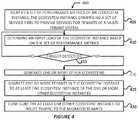
- FIGS. 3-6illustrate various processes for practicing the example embodiments discussed herein.
- the operations of the processes of FIGS. 3-6are described as being performed by elements/components/devices shown and described with regard to FIGS. 1A-2C ; however, other computing devices/systems may operate the depicted processes in a multitude of implementations, arrangements, and/or environments.
- the processesmay be embodied as program code stored in a memory system, which when executed by a processing device or a processor system of a computer device/system, may cause the computer device/system to perform the various operations of such processes.
- one or more general purpose processing device(s)may be transformed into a special purpose processing device(s) configured to perform any of operations described herein responsive to accessing the program code of processes 300 A- 500 of FIGS. 3-6 , respectively, from an electronic memory or computer-readable media. While particular examples and orders of operations are illustrated in FIGS. 3-6 , in various embodiments, these operations may be re-ordered, separated into additional operations, combined, or omitted altogether.
- FIG. 3Aillustrates an example auto-scaling configuration process 300 A, in accordance with various embodiments.
- Process 300 Amay be used to create a configuration to define when an ecosystem 201 should be scaled up or down based on various input load characteristics.
- This configurationmay by an entity, such as a database object or other like data structure, that encapsulates information used by the cloud 200 A (or a management node within the cloud 200 A) to perform the auto-scaling process for ecosystem instances 201 .
- This configurationmay be a collection or set of auto-scaling parameters (or “components”) each of which comprises an auto-scaling parameter value against which various metrics are checked.
- the configurationmay be in any suitable format, such as HTML, XML, JSON, or some other suitable format. Additionally, a GUI may be built to allow the owner/operator/developers of a multi-tenant system to define the configuration.
- Process 300 Amay begin at operation 305 where processing device(s) of a manager node may define indicators that are used to identify an input load of an ecosystem 201 .
- the input load indicatorsmay be used to scale-up or scale-down an ecosystem 201 based on input load characteristics.
- the input loadmay be a measure of work or a workload submitted to a particular ecosystem instance 201 or an individual tier within an ecosystem instance 201 for processing.
- workmay refer to a discrete unit of data calculation, and in some implementations, the discrete unit of data calculation may be based on a cost to perform the discrete unit of work, where the term “cost” may refer to an amount of resources utilized to accomplish one unit of work.
- costmay refer to an amount of resources utilized to accomplish one unit of work.
- workloadmay refer to an amount of work performed by an entity during a period of time or at a particular instant of time.
- a workloadmay be represented as a memory workload (e.g., an amount of memory space needed for program execution to store temporary or permanent data and to perform intermediate computations), processor workload (e.g., a number of instructions being executed by a processor system/device during a given period of time or at a particular time instant), I/O workload (e.g., a number of inputs and outputs or system accesses during a given period of time or at a particular time instant), database workloads (e.g., a number of database queries during a period of time), a network-related workload (e.g., a number of network attachments, a number of user authentications, an amount of data to be transferred over a communications link, etc.), and/or the like.
- memory workloade.g., an amount of memory space needed for program execution to store temporary or permanent data and to perform intermediate computations
- processor workloade.g., a number of instructions being executed by a processor system/device during a given period of time or at a
- workloadmay refer to any of the aforementioned workload types or combinations thereof.
- the input loadmay also use tenant size, or resource consumption per tenant 215 , into account for determining an input load.
- KPIs, KCIs, and other metricsmay also be considered for determining the input load. Examples of KPIs may include response time, latency, throughput, jitter, etc., and/or examples of KCIs may include, inter alia, resource utilization or the like.
- the other metricsmay include, inter alia, output power or power consumption changes for various pods or nodes, code regressions due to software releases, deviations (e.g., increases or decreases) in workload from the customer or system perspectives, deviation (e.g., increases or decreases) in customer transaction demands, a number of negative incidents (e.g., failures, overloads, etc.), etc.
- the processing device(s) of the manager nodemay define waning threshold(s) to trigger auto-scaling, ecosystem spinoff, and/or tenant migration processes.
- the warning threshold(s)may be defined in terms of the input load characteristics discussed previously and/or other ecosystem-specific parameters.
- a single thresholdmay be defined, which when reached, may trigger execution of a spin-off procedure to generate one or more new ecosystems 201 .
- This mechanismmay operate in a same or similar manner as discussed with regard to FIG. 2B , and this mechanism may co-exist with existing KPI and KCI based scaling processes discussed previously.
- multiple thresholdsmay be defined for triggering auto-scaling, spinning off new ecosystems 201 , and migrating tenants 215 to different ecosystems 201 .
- a low warning threshold and a high warning thresholdmay be defined.
- the processing device(s)may trigger an auto-scaling process to scale up or scale down a particular ecosystem instance 201 and/or individual nodes or resources in a given tier.
- the processing device(s)may trigger a spin-off procedure for generating one or more new ecosystem instances 201 .
- the low warning thresholdmay be a lower input load value than an input load value of the high warning threshold (e.g., low warning threshold ⁇ high warning threshold).
- different thresholdsmay be defined for different ecosystem instances 201 based on their input load characteristics and/or ecosystem parameters.
- the low and high thresholdsmay be used to spin-off new ecosystem instances 215 and to migrate tenants 215 .
- new ecosystem instances 215may be generated or spun off when the low warning threshold is reached, and one or more tenants 215 may be proactively migrated out to the new ecosystem instances 215 when the high warning threshold is reached.
- low, medium, and high warning thresholdsmay be defined.
- warning thresholdsmay be defined where the auto-scale process may be triggered when a low warning threshold is reached
- a new ecosystem instance 201may be generated when a medium warning threshold is reached
- one or more tenants 215may be migrated out to the new ecosystem instances 215 when a high warning threshold is reached.
- Tenant-level parameters that influences the input load, KPIs, and KCIsmay also be monitored and used as a basis for migrating tenants to different ecosystem instances.
- KPIsmay include metrics such as response time, latency, throughput, jitter, etc.
- KCIsmay include metrics such as resource utilization or the like.
- various metricsmay be monitored and collected to determine their individual effect on the KPIs and KCIs.
- the metricsmay be monitored/collected to determine their individual effect on the KPIs and KCIs on individual tiers. The compiling/aggregation of the metrics may be conducted on a periodic basis or based on various trigger events.
- Examples of the metric types to be measuredmay include component level metrics, system level metrics, and/or business level metrics.
- Component level metricsmay include measurements of hardware resources of one or more nodes that implement individual tiers, such as database tier (db_tier) measurements, application tier (app_tier) measurements, and load balancing tier (lb_tier) measurements, and the like.
- the db_tier metricsmay include measurements such as DB size(s), DB processor/processing utilization or overall DB processor resource consumption, DB time (an elapsed processing time accumulated from elapsed times of non-idle sessions), DB processor time (e.g., an amount of time that the processor systems of the DB system 16 spend on DB user-level calls (in microseconds)), DB processor time ratio (e.g., DB processor time divided by the db time), DB processor non-idle wait times, DB processor power usage or consumption, storage area network (SAN) input/output (IO) measurements, and/or the like.
- measurementssuch as DB size(s), DB processor/processing utilization or overall DB processor resource consumption, DB time (an elapsed processing time accumulated from elapsed times of non-idle sessions), DB processor time (e.g., an amount of time that the processor systems of the DB system 16 spend on DB user-level calls (in microseconds)),
- the SAN IO metricsmay include measurements such as, an amount of read and/or write operations that can be achieved per unit of time (e.g., IO operations per second (IOPS)), a size of each IO request, based on how much throughput data storage devices can deliver (e.g., average IO size multiplied by IOPS, which may be expressed in megabytes per second (MB/s)), IO response times and/or IO latency times, IO queue sizes.
- IOPSIO operations per second
- IOPSaverage IO size multiplied by IOPS, which may be expressed in megabytes per second (MB/s)
- IO response times and/or IO latency timesIO queue sizes.
- the SAN IO measurementsmay be taken of physical and/or virtual storage systems.
- the app_tier metricsmay include measurements such as application processor (e.g., for particular app server 100 processor system components) usage or utilization, application processor idle time, host system memory usage, application processor time, application processor time ratio, application processor non-idle wait times, application processor power usage or consumption, etc.
- the lb_tiermetricsmay include measurements such as load balancer processor usage or utilization (e.g., for particular load balancers 228 ), load balancer processor idle time, load balancer memory usage, load balancer processor time, load balancer processor time ratio, load balancer processor non-idle wait times, load balancer processor power usage or consumption, etc.
- the system level metricsmay include measurements of system accesses, such as average page time (APT), number of transactions, number or user requests, average size or user requests, average size of DB queries, number of user responses, average response time, number of requests to access individual resources or tenant data, and the like.
- the business level metricsmay include measurements such as a number of incidents (failures, errors, etc.); a number of active tenants 215 per node or ecosystem 201 ; and/or the like.
- the processing device(s) of the manager nodemay identify the tenant-level parameters based on a correlation of the monitored metrics/measurements of individual ecosystem instances 201 and/or individual tiers with various performance service level agreement (SLA) metrics, KPIs, KCIs, or some other baseline metrics or thresholds. Based on the correlation(s), the processing device(s) may identify one or more monitored metrics that drive or otherwise impact performance and/or user/customer experience at individual tiers.
- SLAperformance service level agreement
- the processing device(s) of the manager nodemay define a maximum tenant-size based on the tenant-level parameters.
- an ecosystem 201may include one or more tenants 215 , however, an individual tenant 215 may only exist in one ecosystem 201 .
- An individual tenant 215may only move between ecosystems 201 via an tenant or ecosystem migration.
- Tenant migrationtypically occurs when overload scenarios occur, or may take place for load balancing purposes.
- a maximum tenant sizemay be defined in order to limit how large an ecosystem 201 may be enlarged.
- the maximum tenant sizemay be defined according to the various tenant-level parameters or metrics discussed previously.
- the maximum tenant size for an ecosystem 201may be defined in terms of a maximum amount of db_tier, app_tier, and/or lb_tier resources being consumed by a particular tenant 215 .
- the tenant sizes of different tenants 215may be different from one another. For example, a first tenant 215 may be allocated a first amount of resources based on a first subscription or data plan, and a second tenant 215 may be allocated a second amount of resources based on a second subscription or data plan. In this example, the amount of resources allocated to a tenant 215 may dictate the tenant size for that tenant 215 .
- the processing device(s) of the manager nodemay define warning thresholds to re-categorize tenants to the defined tenant size. When these warning thresholds are reached, the processing device(s) may re-categorize or scale a given tenant 215 to the defined tenant size, or cause the tenant to be migrated to a new ecosystem instance 201 .
- FIG. 3Bshows a proactive tenant monitoring and migration configuration process 300 B, in accordance with various embodiments.
- Process 300 Bmay begin at operation 330 where the processing device(s) may define a maximum number of nodes to which individual subsystems (or tiers) are to be scaled.
- the upper bounds of a number of nodes that a subsystem/tier or ecosystem 201 may be scaled-out tomay be defined.
- the maximum number of nodesmay be defined in terms of physical and/or virtual devices/components, and/or in terms of nodes for individual tiers.
- the processing device(s)may identify and/or define tenant-level parameters that influence KPIs and/or KCIs.
- the processing device(s)may define a maximum tenant-size based on the tenant-level parameters.
- the processing device(s)may define a maximum tenant size to which an ecosystem instance 201 may scale up.
- the upper bounds of a number of tenants 215 that a subsystem/tier or ecosystem 201 may be scaled-out toare defined.
- the maximum number of tenants 215may be defined in terms of the amount of resources allocated to a particular tenant 215 , an amount of physical and/or virtual resources consumed by a particular tenant 215 (which may be on a tier-level basis), and/or using other like criteria.
- the processing device(s)may define tenant size threshold(s) to trigger a spin-off process and/or a tenant migration process.
- the processing device(s)may begin generating one or more new ecosystem instances 201 .
- a determinationmay be made as to a specific size of each environment instance 201 to be spun off.
- the ecosystem size determinationmay be based on current input load characteristics and/or a current size of each tenant 215 within the current ecosystem 201 .
- individual ecosystem instances 201 to be generatedmay also have a defined maximum number of tenants 215 based on available and/or maximum resources allocated to a particular ecosystem instance 201 .
- tenants 215may be automatically migrated to new ecosystems 201 once the new ecosystems 201 are generated.
- the ecosystem size and tenant sizesmay be determined for each newly generated ecosystem 201 , and a particular ecosystem instance 201 may be selected for a particular tenant 215 based on its tenant size. For example, referring to FIG. 2C , a first tenant having a first size may be migrated to ecosystem 201 - 1 and a second tenant having a second size may be migrated to ecosystem 201 -N, where the first size is larger than the second size.
- Various load balancing mechanismsmay be used to select tenants 215 to be migrated to different ecosystems 201 to achieve load balancing among the ecosystem instances 201 .
- the processing device(s) of the manager nodemay define configuration parameters for newly generated ecosystem instances 201 .
- the configuration parametersmay include assigning new network addresses (e.g., IP addresses), host names, domain names, server/machine names, etc.; updating various routing tables; and/or other like parameters.
- FIG. 4illustrates a spin-off and proactive tenant migration process 400 , in accordance with various embodiments.
- Process 400may begin at operation 405 where processing device(s) of a manager node may identify a set of performance metrics of an ecosystem instance 201 , where the ecosystem instance 201 may comprise a set of service tiers to provide services for tenants of a multi-tenant system.
- the service tiersmay include the LB tier 211 , the app tier 212 , and the DB tier 213 discussed previously with regard to FIGS. 2B-2C .
- the processing device(s)may determine an input load of the ecosystem instance 201 based on the set of performance metrics. The identification of the input load may be based on the input load indicators defined using one of processes 300 A-B of FIG. 3 .
- the processing device(s) of the manager nodemay determine whether a trigger has been detected. In embodiments, the trigger may be detected upon the occurrence of an event, such as reaching or breaching one of the defined warning thresholds discussed previously with regard to processes 300 A-B of FIG. 3 .
- the processing device(s)may loop back to determine the input load characteristics at operation 410 . If at operation 415 the processing device(s) determine that a trigger has been detected, the processing device(s) may proceed to operation 420 to generate one or more other ecosystem instances 201 .
- the generating the one or more other ecosystem instances 201may be referred to as spinning-off the ecosystem instance 201 or the like.
- the processing device(s)may migrate one or more tenants 215 from the ecosystem instance 201 to at least one other ecosystem instance 201 of the one or more other ecosystem instances 201 , which were generated at operation 420 .
- the processing device(s)may configure the at least one other ecosystem instance 201 to route traffic to the migrated tenants 215 . After performance of operation 530 , process 400 may end or repeat as necessary.
- the processing device(s) of the manager nodemay determine whether an auto-scale trigger has been detected.
- the auto-scale triggermay be detected upon the occurrence of reaching or breaching a low warning threshold as discussed previously, and may be used to trigger an ecosystem auto-scaling process.
- the processing device(s)may determine whether the low warning threshold has been reached or breached based on the input load determined at operation 510 and/or the performance metrics identified at operation 505 . If at operation 515 the processing device(s) determine that the auto-scale trigger has not been detected, the processing device(s) may loop back to perform operation 510 to determine the input load of the ecosystem instance 201 . If at operation 515 the processing device(s) determine that the auto-scale trigger has been detected, the processing device(s) may proceed to operation 520 to scale an ecosystem size of the ecosystem instance 201 based on an input load.
- the processing device(s) of the manager nodemay determine whether a spin-off trigger has been detected.
- the spin-off triggermay be detected upon the occurrence of reaching or breaching a medium warning threshold as discussed previously, and may be used to trigger an ecosystem spin-off process.
- the processing device(s)may determine whether the medium warning threshold has been reached or breached based on the input load determined at operation 510 and/or the performance metrics identified at operation 505 . If at operation 525 the processing device(s) determine that the spin-off trigger has not been detected, the processing device(s) may loop back to perform operation 510 to determine the input load of the ecosystem instance 201 .
- the processing device(s)may proceed to operation 530 to generate one or more other ecosystem instances 201 , which may be based on the input load. Generating the one or more other ecosystem instances 201 may be referred to as spinning-off the ecosystem instance 201 or the like.
- the processing device(s) of the manager nodemay determine whether a tenant migration trigger has been detected.
- the tenant migration triggermay be detected upon the occurrence of reaching or breaching a high warning threshold as discussed previously, and may be used to trigger an tenant migration process.
- the processing device(s)may determine whether the high warning threshold has been reached or breached based on the input load determined at operation 510 and/or the performance metrics identified at operation 505 . If at operation 535 the processing device(s) determine that the tenant migration trigger has not been detected, the processing device(s) may loop back to perform operation 510 to determine the input load of the ecosystem instance 201 .
- the processing device(s) of the manager nodemay proceed to operation 540 to generate one or more other ecosystem instances 201 migrate one or more tenants 215 from the ecosystem instance 201 to at least one other ecosystem instance 201 of the one or more other ecosystem instances 201 , which were generated at operation 530 .
- the processing device(s) of the manager nodemay configure the at least one other ecosystem instance 201 to route traffic to the migrated tenants 215 .
- process 500may end or repeat as necessary.
- the software codecan be stored as a computer- or processor-executable instructions or commands on a physical non-transitory computer-readable medium.
- suitable mediainclude random access memory (RAM), read only memory (ROM), magnetic media such as a hard-drive or a floppy disk, or an optical medium such as a compact disk (CD) or DVD (digital versatile disk), flash memory, and the like, or any combination of such storage or transmission devices.
- Computer-readable media encoded with the software/program codemay be packaged with a compatible device or provided separately from other devices (for example, via Internet download). Any such computer-readable medium may reside on or within a single computing device or an entire computer system, and may be among other computer-readable media within a system or network.
- a computer system, or other computing devicemay include a monitor, printer, or other suitable display for providing any of the results mentioned herein to a user.
Landscapes
- Engineering & Computer Science (AREA)
- Computer Networks & Wireless Communication (AREA)
- Signal Processing (AREA)
- Databases & Information Systems (AREA)
- Theoretical Computer Science (AREA)
- General Engineering & Computer Science (AREA)
- Physics & Mathematics (AREA)
- Data Mining & Analysis (AREA)
- General Physics & Mathematics (AREA)
- Computer Hardware Design (AREA)
- Computing Systems (AREA)
- Environmental & Geological Engineering (AREA)
- Management, Administration, Business Operations System, And Electronic Commerce (AREA)
Abstract
Description
Claims (20)
Priority Applications (1)
| Application Number | Priority Date | Filing Date | Title |
|---|---|---|---|
| US15/910,899US10853334B2 (en) | 2018-03-02 | 2018-03-02 | Technologies for providing service isolation, scalability, and proactive tenant migration in multi-tenant ecosystems |
Applications Claiming Priority (1)
| Application Number | Priority Date | Filing Date | Title |
|---|---|---|---|
| US15/910,899US10853334B2 (en) | 2018-03-02 | 2018-03-02 | Technologies for providing service isolation, scalability, and proactive tenant migration in multi-tenant ecosystems |
Publications (2)
| Publication Number | Publication Date |
|---|---|
| US20190272331A1 US20190272331A1 (en) | 2019-09-05 |
| US10853334B2true US10853334B2 (en) | 2020-12-01 |
Family
ID=67768599
Family Applications (1)
| Application Number | Title | Priority Date | Filing Date |
|---|---|---|---|
| US15/910,899Active2038-12-03US10853334B2 (en) | 2018-03-02 | 2018-03-02 | Technologies for providing service isolation, scalability, and proactive tenant migration in multi-tenant ecosystems |
Country Status (1)
| Country | Link |
|---|---|
| US (1) | US10853334B2 (en) |
Cited By (3)
| Publication number | Priority date | Publication date | Assignee | Title |
|---|---|---|---|---|
| US11177973B2 (en) | 2020-01-10 | 2021-11-16 | Salesforce.Com, Inc. | Distributed audience computation software service |
| US20240235944A9 (en)* | 2021-02-24 | 2024-07-11 | Open Source Consulting Inc. | Cloud migration data analysis method using system process information, and system thereof |
| US12399872B2 (en) | 2023-01-17 | 2025-08-26 | Salesforce, Inc. | Intelligent service for data migration |
Families Citing this family (24)
| Publication number | Priority date | Publication date | Assignee | Title |
|---|---|---|---|---|
| US10853334B2 (en)* | 2018-03-02 | 2020-12-01 | Salesforce.Com, Inc. | Technologies for providing service isolation, scalability, and proactive tenant migration in multi-tenant ecosystems |
| US20190386928A1 (en)* | 2018-06-19 | 2019-12-19 | R-Stor Inc. | System and method for utilizing idle network resources |
| WO2020099924A1 (en)* | 2018-11-08 | 2020-05-22 | Iagon As | Intelligent, decentralized and autonomous marketplace for distributed computing and storage |
| US11455315B1 (en)* | 2018-12-11 | 2022-09-27 | Palantir Technologies Inc. | Central user interface for accessing and upgrading of dataset integrations |
| US11775402B2 (en) | 2019-01-21 | 2023-10-03 | Harmonic, Inc. | High availability and software upgrades in network software |
| US11321200B1 (en)* | 2019-01-21 | 2022-05-03 | Harmonic, Inc. | High availability and software upgrades in a virtual cable modem termination system |
| US11381491B2 (en)* | 2019-04-15 | 2022-07-05 | Netscout Systems, Inc. | System and method for load balancing of network packets received from a MME with smart clustering |
| US11755394B2 (en)* | 2020-01-31 | 2023-09-12 | Salesforce, Inc. | Systems, methods, and apparatuses for tenant migration between instances in a cloud based computing environment |
| US11222035B2 (en)* | 2020-03-03 | 2022-01-11 | Sap Se | Centralized multi-tenancy as a service in cloud-based computing environment |
| US12074762B2 (en)* | 2020-04-15 | 2024-08-27 | Alkira, Inc. | Tenant movement in a multi-tenant system |
| US11379281B2 (en)* | 2020-11-18 | 2022-07-05 | Akamai Technologies, Inc. | Detection and optimization of content in the payloads of API messages |
| JP2022146045A (en)* | 2021-03-22 | 2022-10-05 | 富士通株式会社 | Service management program, service management apparatus, and service management method |
| CN113342827A (en)* | 2021-07-01 | 2021-09-03 | 广东电网有限责任公司 | Power grid data storage method, storage medium and system based on multi-tenant technology |
| US11880874B2 (en) | 2021-08-23 | 2024-01-23 | Shopify Inc. | Systems and methods for server load balancing based on correlated events |
| US12223449B2 (en) | 2021-08-23 | 2025-02-11 | Shopify Inc. | Systems and methods for modifying online stores through scheduling |
| US20230053818A1 (en)* | 2021-08-23 | 2023-02-23 | Shopify Inc. | Systems and methods for modifying online stores |
| US20230119834A1 (en)* | 2021-10-19 | 2023-04-20 | Sap Se | Multi-tenancy using shared databases |
| CN114338384B (en)* | 2021-12-30 | 2024-11-01 | 上海柯林布瑞信息技术有限公司 | Multi-node service rapid networking method and device based on local area network |
| US12028424B2 (en)* | 2022-07-25 | 2024-07-02 | At&T Intellectual Property I, L.P. | Cloud deployment of network function software with a management manifest |
| CN115062000A (en)* | 2022-08-05 | 2022-09-16 | 深圳竹云科技股份有限公司 | Data isolation method and device, computer equipment and storage medium |
| US20240086218A1 (en)* | 2022-09-08 | 2024-03-14 | Oracle International Corporation | Transmitting metric data between tenancies |
| US12210499B1 (en)* | 2023-07-21 | 2025-01-28 | Bank Of America Corporation | Collaborative automated system for intelligent storage forecasting and abend handling |
| US12204554B1 (en) | 2023-07-21 | 2025-01-21 | Bank Of America Corporation | Collaborative automated system for intelligent storage forecasting and abend handling |
| CN118860269A (en)* | 2024-01-24 | 2024-10-29 | 上海宝信软件股份有限公司 | Data writing channel management method and system for tenant-level resource isolation |
Citations (158)
| Publication number | Priority date | Publication date | Assignee | Title |
|---|---|---|---|---|
| US5577188A (en) | 1994-05-31 | 1996-11-19 | Future Labs, Inc. | Method to provide for virtual screen overlay |
| US5608872A (en) | 1993-03-19 | 1997-03-04 | Ncr Corporation | System for allowing all remote computers to perform annotation on an image and replicating the annotated image on the respective displays of other comuters |
| US5649104A (en) | 1993-03-19 | 1997-07-15 | Ncr Corporation | System for allowing user of any computer to draw image over that generated by the host computer and replicating the drawn image to other computers |
| US5715450A (en) | 1995-09-27 | 1998-02-03 | Siebel Systems, Inc. | Method of selecting and presenting data from a database using a query language to a user of a computer system |
| US5821937A (en) | 1996-02-23 | 1998-10-13 | Netsuite Development, L.P. | Computer method for updating a network design |
| US5831610A (en) | 1996-02-23 | 1998-11-03 | Netsuite Development L.P. | Designing networks |
| US5873096A (en) | 1997-10-08 | 1999-02-16 | Siebel Systems, Inc. | Method of maintaining a network of partially replicated database system |
| US5918159A (en) | 1997-08-04 | 1999-06-29 | Fomukong; Mundi | Location reporting satellite paging system with optional blocking of location reporting |
| US5963953A (en) | 1998-03-30 | 1999-10-05 | Siebel Systems, Inc. | Method, and system for product configuration |
| US5983227A (en) | 1997-06-12 | 1999-11-09 | Yahoo, Inc. | Dynamic page generator |
| US6092083A (en) | 1997-02-26 | 2000-07-18 | Siebel Systems, Inc. | Database management system which synchronizes an enterprise server and a workgroup user client using a docking agent |
| US6161149A (en) | 1998-03-13 | 2000-12-12 | Groupserve, Inc. | Centrifugal communication and collaboration method |
| US6169534B1 (en) | 1997-06-26 | 2001-01-02 | Upshot.Com | Graphical user interface for customer information management |
| US6178425B1 (en) | 1997-02-26 | 2001-01-23 | Siebel Systems, Inc. | Method of determining the visibility to a remote database client of a plurality of database transactions using simplified visibility rules |
| US6216135B1 (en) | 1997-02-26 | 2001-04-10 | Siebel Systems, Inc. | Method of determining visibility to a remote database client of a plurality of database transactions having variable visibility strengths |
| US6216133B1 (en) | 1995-06-09 | 2001-04-10 | U.S. Phi,Ips Corporation | Method for enabling a user to fetch a specific information item from a set of information items, and a system for carrying out such a method |
| US6233617B1 (en) | 1997-02-26 | 2001-05-15 | Siebel Systems, Inc. | Determining the visibility to a remote database client |
| US6236978B1 (en) | 1997-11-14 | 2001-05-22 | New York University | System and method for dynamic profiling of users in one-to-one applications |
| US6266669B1 (en) | 1997-02-28 | 2001-07-24 | Siebel Systems, Inc. | Partially replicated distributed database with multiple levels of remote clients |
| US6288717B1 (en) | 1999-03-19 | 2001-09-11 | Terry Dunkle | Headline posting algorithm |
| US6295530B1 (en) | 1995-05-15 | 2001-09-25 | Andrew M. Ritchie | Internet service of differently formatted viewable data signals including commands for browser execution |
| US20010044791A1 (en) | 2000-04-14 | 2001-11-22 | Richter James Neal | Automated adaptive classification system for bayesian knowledge networks |
| US6324693B1 (en) | 1997-03-12 | 2001-11-27 | Siebel Systems, Inc. | Method of synchronizing independently distributed software and database schema |
| US6324568B1 (en) | 1999-11-30 | 2001-11-27 | Siebel Systems, Inc. | Method and system for distributing objects over a network |
| US6336137B1 (en) | 2000-03-31 | 2002-01-01 | Siebel Systems, Inc. | Web client-server system and method for incompatible page markup and presentation languages |
| USD454139S1 (en) | 2001-02-20 | 2002-03-05 | Rightnow Technologies | Display screen for a computer |
| US6367077B1 (en) | 1997-02-27 | 2002-04-02 | Siebel Systems, Inc. | Method of upgrading a software application in the presence of user modifications |
| US6393605B1 (en) | 1998-11-18 | 2002-05-21 | Siebel Systems, Inc. | Apparatus and system for efficient delivery and deployment of an application |
| US20020072951A1 (en) | 1999-03-03 | 2002-06-13 | Michael Lee | Marketing support database management method, system and program product |
| US6411949B1 (en) | 1999-08-12 | 2002-06-25 | Koninklijke Philips Electronics N.V., | Customizing database information for presentation with media selections |
| US20020082892A1 (en) | 1998-08-27 | 2002-06-27 | Keith Raffel | Method and apparatus for network-based sales force management |
| US6434550B1 (en) | 2000-04-14 | 2002-08-13 | Rightnow Technologies, Inc. | Temporal updates of relevancy rating of retrieved information in an information search system |
| US6446089B1 (en) | 1997-02-26 | 2002-09-03 | Siebel Systems, Inc. | Method of using a cache to determine the visibility to a remote database client of a plurality of database transactions |
| US20020140731A1 (en) | 2001-03-28 | 2002-10-03 | Pavitra Subramaniam | Engine to present a user interface based on a logical structure, such as one for a customer relationship management system, across a web site |
| US20020143997A1 (en) | 2001-03-28 | 2002-10-03 | Xiaofei Huang | Method and system for direct server synchronization with a computing device |
| US20020162090A1 (en) | 2001-04-30 | 2002-10-31 | Parnell Karen P. | Polylingual simultaneous shipping of software |
| US20020165742A1 (en) | 2000-03-31 | 2002-11-07 | Mark Robins | Feature centric release manager method and system |
| US20030004971A1 (en) | 2001-06-29 | 2003-01-02 | Gong Wen G. | Automatic generation of data models and accompanying user interfaces |
| US20030018830A1 (en) | 2001-02-06 | 2003-01-23 | Mingte Chen | Adaptive communication application programming interface |
| US20030018705A1 (en) | 2001-03-31 | 2003-01-23 | Mingte Chen | Media-independent communication server |
| US6535909B1 (en) | 1999-11-18 | 2003-03-18 | Contigo Software, Inc. | System and method for record and playback of collaborative Web browsing session |
| US20030066032A1 (en) | 2001-09-28 | 2003-04-03 | Siebel Systems,Inc. | System and method for facilitating user interaction in a browser environment |
| US20030066031A1 (en) | 2001-09-28 | 2003-04-03 | Siebel Systems, Inc. | Method and system for supporting user navigation in a browser environment |
| US20030070004A1 (en) | 2001-09-29 | 2003-04-10 | Anil Mukundan | Method, apparatus, and system for implementing a framework to support a web-based application |
| US20030070005A1 (en) | 2001-09-29 | 2003-04-10 | Anil Mukundan | Method, apparatus, and system for implementing view caching in a framework to support web-based applications |
| US20030070000A1 (en) | 2001-09-29 | 2003-04-10 | John Coker | Computing system and method to implicitly commit unsaved data for a World Wide Web application |
| US20030069936A1 (en) | 2001-10-09 | 2003-04-10 | Warner Douglas K. | Method for routing electronic correspondence based on the level and type of emotion contained therein |
| US20030074418A1 (en) | 2001-09-29 | 2003-04-17 | John Coker | Method, apparatus and system for a mobile web client |
| US6553563B2 (en) | 1998-11-30 | 2003-04-22 | Siebel Systems, Inc. | Development tool, method, and system for client server applications |
| US6560461B1 (en) | 1997-08-04 | 2003-05-06 | Mundi Fomukong | Authorized location reporting paging system |
| US6574635B2 (en) | 1999-03-03 | 2003-06-03 | Siebel Systems, Inc. | Application instantiation based upon attributes and values stored in a meta data repository, including tiering of application layers objects and components |
| US6577726B1 (en) | 2000-03-31 | 2003-06-10 | Siebel Systems, Inc. | Computer telephony integration hotelling method and system |
| US6601087B1 (en) | 1998-11-18 | 2003-07-29 | Webex Communications, Inc. | Instant document sharing |
| US6604117B2 (en) | 1996-03-19 | 2003-08-05 | Siebel Systems, Inc. | Method of maintaining a network of partially replicated database system |
| US20030151633A1 (en) | 2002-02-13 | 2003-08-14 | David George | Method and system for enabling connectivity to a data system |
| US20030159136A1 (en) | 2001-09-28 | 2003-08-21 | Huang Xiao Fei | Method and system for server synchronization with a computing device |
| US6621834B1 (en) | 1999-11-05 | 2003-09-16 | Raindance Communications, Inc. | System and method for voice transmission over network protocols |
| US20030189600A1 (en) | 2002-03-29 | 2003-10-09 | Prasad Gune | Defining an approval process for requests for approval |
| US20030204427A1 (en) | 2002-03-29 | 2003-10-30 | Prasad Gune | User interface for processing requests for approval |
| US20030206192A1 (en) | 2001-03-31 | 2003-11-06 | Mingte Chen | Asynchronous message push to web browser |
| US6654032B1 (en) | 1999-12-23 | 2003-11-25 | Webex Communications, Inc. | Instant sharing of documents on a remote server |
| US20030225730A1 (en) | 2002-06-03 | 2003-12-04 | Rightnow Technologies, Inc. | System and method for generating a dynamic interface via a communications network |
| US6665655B1 (en) | 2000-04-14 | 2003-12-16 | Rightnow Technologies, Inc. | Implicit rating of retrieved information in an information search system |
| US6665648B2 (en) | 1998-11-30 | 2003-12-16 | Siebel Systems, Inc. | State models for monitoring process |
| US20040001092A1 (en) | 2002-06-27 | 2004-01-01 | Rothwein Thomas M. | Prototyping graphical user interfaces |
| US20040010489A1 (en) | 2002-07-12 | 2004-01-15 | Rightnow Technologies, Inc. | Method for providing search-specific web pages in a network computing environment |
| US20040015981A1 (en) | 2002-06-27 | 2004-01-22 | Coker John L. | Efficient high-interactivity user interface for client-server applications |
| US20040027388A1 (en) | 2002-06-27 | 2004-02-12 | Eric Berg | Method and apparatus to facilitate development of a customer-specific business process model |
| US6711565B1 (en) | 2001-06-18 | 2004-03-23 | Siebel Systems, Inc. | Method, apparatus, and system for previewing search results |
| US6724399B1 (en) | 2001-09-28 | 2004-04-20 | Siebel Systems, Inc. | Methods and apparatus for enabling keyboard accelerators in applications implemented via a browser |
| US6728702B1 (en) | 2001-06-18 | 2004-04-27 | Siebel Systems, Inc. | System and method to implement an integrated search center supporting a full-text search and query on a database |
| US6728960B1 (en) | 1998-11-18 | 2004-04-27 | Siebel Systems, Inc. | Techniques for managing multiple threads in a browser environment |
| US6732111B2 (en) | 1998-03-03 | 2004-05-04 | Siebel Systems, Inc. | Method, apparatus, system, and program product for attaching files and other objects to a partially replicated database |
| US6732100B1 (en) | 2000-03-31 | 2004-05-04 | Siebel Systems, Inc. | Database access method and system for user role defined access |
| US6732095B1 (en) | 2001-04-13 | 2004-05-04 | Siebel Systems, Inc. | Method and apparatus for mapping between XML and relational representations |
| US20040128001A1 (en) | 2002-08-28 | 2004-07-01 | Levin Issac Stephen | Method and apparatus for an integrated process modeller |
| US6763501B1 (en) | 2000-06-09 | 2004-07-13 | Webex Communications, Inc. | Remote document serving |
| US6763351B1 (en) | 2001-06-18 | 2004-07-13 | Siebel Systems, Inc. | Method, apparatus, and system for attaching search results |
| US6768904B2 (en) | 2000-10-11 | 2004-07-27 | Lg Electronics Inc. | Data communication method using mobile terminal |
| US6772229B1 (en) | 2000-11-13 | 2004-08-03 | Groupserve, Inc. | Centrifugal communication and collaboration method |
| US6782383B2 (en) | 2001-06-18 | 2004-08-24 | Siebel Systems, Inc. | System and method to implement a persistent and dismissible search center frame |
| US20040186860A1 (en) | 2003-03-21 | 2004-09-23 | Wen-Hsin Lee | Method and architecture for providing data-change alerts to external applications via a push service |
| US20040193510A1 (en) | 2003-03-25 | 2004-09-30 | Catahan Nardo B. | Modeling of order data |
| US20040199543A1 (en) | 2003-04-04 | 2004-10-07 | Braud Luke A. | Facilitating data manipulation in a browser-based user interface of an enterprise business application |
| US20040199536A1 (en) | 2003-03-24 | 2004-10-07 | Barnes Leon Maria Theresa | Product common object |
| US20040199489A1 (en) | 2003-03-24 | 2004-10-07 | Barnes-Leon Maria Theresa | Custom common object |
| US6804330B1 (en) | 2002-01-04 | 2004-10-12 | Siebel Systems, Inc. | Method and system for accessing CRM data via voice |
| US6826745B2 (en) | 1998-11-30 | 2004-11-30 | Siebel Systems, Inc. | System and method for smart scripting call centers and configuration thereof |
| US6826582B1 (en) | 2001-09-28 | 2004-11-30 | Emc Corporation | Method and system for using file systems for content management |
| US6829655B1 (en) | 2001-03-28 | 2004-12-07 | Siebel Systems, Inc. | Method and system for server synchronization with a computing device via a companion device |
| US20040249854A1 (en) | 2003-03-24 | 2004-12-09 | Barnes-Leon Maria Theresa | Common common object |
| US20040260534A1 (en) | 2003-06-19 | 2004-12-23 | Pak Wai H. | Intelligent data search |
| US20040260659A1 (en) | 2003-06-23 | 2004-12-23 | Len Chan | Function space reservation system |
| US20040268299A1 (en) | 2003-06-30 | 2004-12-30 | Shu Lei | Application user interface template with free-form layout |
| US6842748B1 (en) | 2000-04-14 | 2005-01-11 | Rightnow Technologies, Inc. | Usage based strength between related information in an information retrieval system |
| US6850895B2 (en) | 1998-11-30 | 2005-02-01 | Siebel Systems, Inc. | Assignment manager |
| US20050050555A1 (en) | 2003-08-28 | 2005-03-03 | Exley Richard Mark | Universal application network architecture |
| US6907566B1 (en) | 1999-04-02 | 2005-06-14 | Overture Services, Inc. | Method and system for optimum placement of advertisements on a webpage |
| US7062502B1 (en) | 2001-12-28 | 2006-06-13 | Kesler John N | Automated generation of dynamic data entry user interface for relational database management systems |
| US7069231B1 (en) | 2000-07-20 | 2006-06-27 | Oracle International Corporation | Methods and systems for defining, applying and executing customer care relationship plans |
| US7069197B1 (en) | 2001-10-25 | 2006-06-27 | Ncr Corp. | Factor analysis/retail data mining segmentation in a data mining system |
| US7181758B1 (en) | 1994-07-25 | 2007-02-20 | Data Innovation, L.L.C. | Information distribution and processing system |
| US7269590B2 (en) | 2004-01-29 | 2007-09-11 | Yahoo! Inc. | Method and system for customizing views of information associated with a social network user |
| US7289976B2 (en) | 2004-12-23 | 2007-10-30 | Microsoft Corporation | Easy-to-use data report specification |
| US7340411B2 (en) | 1998-02-26 | 2008-03-04 | Cook Rachael L | System and method for generating, capturing, and managing customer lead information over a computer network |
| US7356482B2 (en) | 1998-12-18 | 2008-04-08 | Alternative Systems, Inc. | Integrated change management unit |
| US7406501B2 (en) | 2003-03-24 | 2008-07-29 | Yahoo! Inc. | System and method for instant messaging using an e-mail protocol |
| US7412455B2 (en) | 2003-04-30 | 2008-08-12 | Dillon David M | Software framework that facilitates design and implementation of database applications |
| US7454509B2 (en) | 1999-11-10 | 2008-11-18 | Yahoo! Inc. | Online playback system with community bias |
| US20090063415A1 (en) | 2007-08-31 | 2009-03-05 | Business Objects, S.A. | Apparatus and method for dynamically selecting componentized executable instructions at run time |
| US7508789B2 (en) | 1994-04-07 | 2009-03-24 | Data Innovation Llc | Information distribution and processing system |
| US20090100342A1 (en) | 2007-10-12 | 2009-04-16 | Gabriel Jakobson | Method and system for presenting address and mapping information |
| US20090177744A1 (en) | 2008-01-04 | 2009-07-09 | Yahoo! Inc. | Identifying and employing social network relationships |
| US7603483B2 (en) | 2001-03-23 | 2009-10-13 | Cisco Technology, Inc. | Method and system for class-based management of dynamic content in a networked environment |
| US7620655B2 (en) | 2003-05-07 | 2009-11-17 | Enecto Ab | Method, device and computer program product for identifying visitors of websites |
| US7644122B2 (en) | 1999-11-23 | 2010-01-05 | Frank Michael Weyer | Method apparatus and business system for online communications with online and offline recipients |
| US7668861B2 (en) | 2000-02-14 | 2010-02-23 | Yahoo! Inc. | System and method to determine the validity of an interaction on a network |
| US7698160B2 (en) | 1999-05-07 | 2010-04-13 | Virtualagility, Inc | System for performing collaborative tasks |
| US7730478B2 (en) | 2006-10-04 | 2010-06-01 | Salesforce.Com, Inc. | Method and system for allowing access to developed applications via a multi-tenant on-demand database service |
| US7747648B1 (en) | 2005-02-14 | 2010-06-29 | Yahoo! Inc. | World modeling using a relationship network with communication channels to entities |
| US7779039B2 (en) | 2004-04-02 | 2010-08-17 | Salesforce.Com, Inc. | Custom entities and fields in a multi-tenant database system |
| US7779475B2 (en) | 2006-07-31 | 2010-08-17 | Petnote Llc | Software-based method for gaining privacy by affecting the screen of a computing device |
| US7827208B2 (en) | 2006-08-11 | 2010-11-02 | Facebook, Inc. | Generating a feed of stories personalized for members of a social network |
| US7853881B1 (en) | 2006-07-03 | 2010-12-14 | ISQ Online | Multi-user on-line real-time virtual social networks based upon communities of interest for entertainment, information or e-commerce purposes |
| US7945653B2 (en) | 2006-10-11 | 2011-05-17 | Facebook, Inc. | Tagging digital media |
| US8005896B2 (en) | 1998-10-13 | 2011-08-23 | Cheah Ip Llc | System for controlled distribution of user profiles over a network |
| US8014943B2 (en) | 2008-05-08 | 2011-09-06 | Gabriel Jakobson | Method and system for displaying social networking navigation information |
| US20110218958A1 (en) | 2010-03-08 | 2011-09-08 | Salesforce.Com, Inc. | System, method and computer program product for performing one or more actions utilizing a uniform resource locator |
| US8032297B2 (en) | 2008-05-08 | 2011-10-04 | Gabriel Jakobson | Method and system for displaying navigation information on an electronic map |
| US20110247051A1 (en) | 2010-04-01 | 2011-10-06 | Salesforce.Com, Inc. | System, method and computer program product for performing one or more actions based on a determined access permissions for a plurality of users |
| US8073850B1 (en) | 2007-01-19 | 2011-12-06 | Wordnetworks, Inc. | Selecting key phrases for serving contextually relevant content |
| US8082301B2 (en) | 2006-11-10 | 2011-12-20 | Virtual Agility, Inc. | System for supporting collaborative activity |
| US8095413B1 (en) | 1999-05-07 | 2012-01-10 | VirtualAgility, Inc. | Processing management information |
| US8095531B2 (en) | 2006-10-03 | 2012-01-10 | Salesforce.Com, Inc. | Methods and systems for controlling access to custom objects in a database |
| US20120042218A1 (en) | 2010-08-13 | 2012-02-16 | Salesforce.Com, Inc. | Debugging site errors by an admin as a guest user in a multi-tenant database environment |
| US8209308B2 (en) | 2006-05-01 | 2012-06-26 | Rueben Steven L | Method for presentation of revisions of an electronic document |
| US20120233137A1 (en) | 2006-05-01 | 2012-09-13 | Gabriel Jakobson | Presentation of document history in a web browsing application |
| US8490025B2 (en) | 2008-02-01 | 2013-07-16 | Gabriel Jakobson | Displaying content associated with electronic mapping systems |
| US8504945B2 (en) | 2008-02-01 | 2013-08-06 | Gabriel Jakobson | Method and system for associating content with map zoom function |
| US8510043B1 (en) | 2012-03-15 | 2013-08-13 | Transloc Inc. | Systems and methods of displaying route information on an electronic display |
| US8510664B2 (en) | 2008-09-06 | 2013-08-13 | Steven L. Rueben | Method and system for displaying email thread information |
| US20130212497A1 (en) | 2012-02-10 | 2013-08-15 | Liveperson, Inc. | Analytics driven engagement |
| US20130218949A1 (en) | 2012-02-17 | 2013-08-22 | Gabriel Jakobson | Collaborative web browsing system integrated with social networks |
| US20130218948A1 (en) | 2012-02-17 | 2013-08-22 | Gabriel Jakobson | Variable speed collaborative web browsing system |
| US20130218966A1 (en) | 2012-02-17 | 2013-08-22 | Gabriel Jakobson | Collaborative web browsing system having document object model element interaction detection |
| US20130247216A1 (en) | 2008-11-03 | 2013-09-19 | Salesforce.Com, Inc | System, method and computer program product for publicly providing web content of a tenant using a multi-tenant on-demand database service |
| US8566301B2 (en) | 2006-05-01 | 2013-10-22 | Steven L. Rueben | Document revisions in a collaborative computing environment |
| US8646103B2 (en) | 2008-06-30 | 2014-02-04 | Gabriel Jakobson | Method and system for securing online identities |
| US20140359537A1 (en) | 2008-02-01 | 2014-12-04 | Gabriel Jackobson | Online advertising associated with electronic mapping systems |
| US20150106499A1 (en)* | 2013-10-14 | 2015-04-16 | Oracle International Corporation | Transforming cloud service measurements into anonymized extramural business rankings |
| US20170054610A1 (en)* | 2015-08-19 | 2017-02-23 | Microsoft Technology Licensing, Llc | Diagnostic framework in computing systems |
| US20180278725A1 (en)* | 2017-03-24 | 2018-09-27 | Ca, Inc. | Converting a single-tenant application for multi-tenant use |
| US20180316552A1 (en)* | 2017-04-26 | 2018-11-01 | Oracle International Corporation | Provisioning framework for binding related cloud services |
| US20180316551A1 (en)* | 2017-04-26 | 2018-11-01 | Oracle International Corporation | Portable instance provisioning framework for cloud services |
| US20190123973A1 (en)* | 2017-10-24 | 2019-04-25 | Cisco Technology, Inc. | Inter-tenant workload performance correlation and recommendation |
| US20190173765A1 (en)* | 2017-12-04 | 2019-06-06 | Salesforce.Com, Inc. | Technologies for capacity remediation in multi-tenant cloud environments |
| US20190171474A1 (en)* | 2017-12-01 | 2019-06-06 | At&T Intellectual Property I, L.P. | Flow management and flow modeling in network clouds |
| US20190272331A1 (en)* | 2018-03-02 | 2019-09-05 | Salesforce.Com, Inc. | Technologies for providing service isolation, scalability, and proactive tenant migration in multi-tenant ecosystems |
- 2018
- 2018-03-02USUS15/910,899patent/US10853334B2/enactiveActive
Patent Citations (189)
| Publication number | Priority date | Publication date | Assignee | Title |
|---|---|---|---|---|
| US5761419A (en) | 1993-03-19 | 1998-06-02 | Ncr Corporation | Remote collaboration system including first program means translating user inputs into annotations and running on all computers while second program means runs on one computer |
| US5608872A (en) | 1993-03-19 | 1997-03-04 | Ncr Corporation | System for allowing all remote computers to perform annotation on an image and replicating the annotated image on the respective displays of other comuters |
| US5649104A (en) | 1993-03-19 | 1997-07-15 | Ncr Corporation | System for allowing user of any computer to draw image over that generated by the host computer and replicating the drawn image to other computers |
| US5819038A (en) | 1993-03-19 | 1998-10-06 | Ncr Corporation | Collaboration system for producing copies of image generated by first program on first computer on other computers and annotating the image by second program |
| US7508789B2 (en) | 1994-04-07 | 2009-03-24 | Data Innovation Llc | Information distribution and processing system |
| US8457545B2 (en) | 1994-04-07 | 2013-06-04 | Online News Link Llc | Information distribution and processing system |
| US5577188A (en) | 1994-05-31 | 1996-11-19 | Future Labs, Inc. | Method to provide for virtual screen overlay |
| US7181758B1 (en) | 1994-07-25 | 2007-02-20 | Data Innovation, L.L.C. | Information distribution and processing system |
| US6826565B2 (en) | 1995-05-15 | 2004-11-30 | Ablaise Limited | Method and apparatus for serving files to browsing clients |
| US6295530B1 (en) | 1995-05-15 | 2001-09-25 | Andrew M. Ritchie | Internet service of differently formatted viewable data signals including commands for browser execution |
| US6216133B1 (en) | 1995-06-09 | 2001-04-10 | U.S. Phi,Ips Corporation | Method for enabling a user to fetch a specific information item from a set of information items, and a system for carrying out such a method |
| US5715450A (en) | 1995-09-27 | 1998-02-03 | Siebel Systems, Inc. | Method of selecting and presenting data from a database using a query language to a user of a computer system |
| US5821937A (en) | 1996-02-23 | 1998-10-13 | Netsuite Development, L.P. | Computer method for updating a network design |
| US5831610A (en) | 1996-02-23 | 1998-11-03 | Netsuite Development L.P. | Designing networks |
| US6604117B2 (en) | 1996-03-19 | 2003-08-05 | Siebel Systems, Inc. | Method of maintaining a network of partially replicated database system |
| US6189011B1 (en) | 1996-03-19 | 2001-02-13 | Siebel Systems, Inc. | Method of maintaining a network of partially replicated database system |
| US6684438B2 (en) | 1997-02-26 | 2004-02-03 | Siebel Systems, Inc. | Method of using cache to determine the visibility to a remote database client of a plurality of database transactions |
| US6446089B1 (en) | 1997-02-26 | 2002-09-03 | Siebel Systems, Inc. | Method of using a cache to determine the visibility to a remote database client of a plurality of database transactions |
| US6178425B1 (en) | 1997-02-26 | 2001-01-23 | Siebel Systems, Inc. | Method of determining the visibility to a remote database client of a plurality of database transactions using simplified visibility rules |
| US6233617B1 (en) | 1997-02-26 | 2001-05-15 | Siebel Systems, Inc. | Determining the visibility to a remote database client |
| US6092083A (en) | 1997-02-26 | 2000-07-18 | Siebel Systems, Inc. | Database management system which synchronizes an enterprise server and a workgroup user client using a docking agent |
| US6216135B1 (en) | 1997-02-26 | 2001-04-10 | Siebel Systems, Inc. | Method of determining visibility to a remote database client of a plurality of database transactions having variable visibility strengths |
| US20020129352A1 (en) | 1997-02-27 | 2002-09-12 | Brodersen Robert A. | Method and apparatus for upgrading a software application in the presence of user modifications |
| US6367077B1 (en) | 1997-02-27 | 2002-04-02 | Siebel Systems, Inc. | Method of upgrading a software application in the presence of user modifications |
| US6266669B1 (en) | 1997-02-28 | 2001-07-24 | Siebel Systems, Inc. | Partially replicated distributed database with multiple levels of remote clients |
| US6754681B2 (en) | 1997-02-28 | 2004-06-22 | Siebel Systems, Inc. | Partially replicated distributed database with multiple levels of remote clients |
| US6405220B1 (en) | 1997-02-28 | 2002-06-11 | Siebel Systems, Inc. | Partially replicated distributed database with multiple levels of remote clients |
| US6324693B1 (en) | 1997-03-12 | 2001-11-27 | Siebel Systems, Inc. | Method of synchronizing independently distributed software and database schema |
| US5983227A (en) | 1997-06-12 | 1999-11-09 | Yahoo, Inc. | Dynamic page generator |
| US6169534B1 (en) | 1997-06-26 | 2001-01-02 | Upshot.Com | Graphical user interface for customer information management |
| US5918159A (en) | 1997-08-04 | 1999-06-29 | Fomukong; Mundi | Location reporting satellite paging system with optional blocking of location reporting |
| US6560461B1 (en) | 1997-08-04 | 2003-05-06 | Mundi Fomukong | Authorized location reporting paging system |
| US5873096A (en) | 1997-10-08 | 1999-02-16 | Siebel Systems, Inc. | Method of maintaining a network of partially replicated database system |
| US7603331B2 (en) | 1997-11-14 | 2009-10-13 | New York University | System and method for dynamic profiling of users in one-to-one applications and for validating user rules |
| US6236978B1 (en) | 1997-11-14 | 2001-05-22 | New York University | System and method for dynamic profiling of users in one-to-one applications |
| US8103611B2 (en) | 1997-11-14 | 2012-01-24 | New York University | Architectures, systems, apparatus, methods, and computer-readable medium for providing recommendations to users and applications using multidimensional data |
| US7340411B2 (en) | 1998-02-26 | 2008-03-04 | Cook Rachael L | System and method for generating, capturing, and managing customer lead information over a computer network |
| US6732111B2 (en) | 1998-03-03 | 2004-05-04 | Siebel Systems, Inc. | Method, apparatus, system, and program product for attaching files and other objects to a partially replicated database |
| US6161149A (en) | 1998-03-13 | 2000-12-12 | Groupserve, Inc. | Centrifugal communication and collaboration method |
| US8015495B2 (en) | 1998-03-13 | 2011-09-06 | Groupserve It Trust Llc | Centrifugal communication and collaboration method |
| US5963953A (en) | 1998-03-30 | 1999-10-05 | Siebel Systems, Inc. | Method, and system for product configuration |
| US20020082892A1 (en) | 1998-08-27 | 2002-06-27 | Keith Raffel | Method and apparatus for network-based sales force management |
| US8005896B2 (en) | 1998-10-13 | 2011-08-23 | Cheah Ip Llc | System for controlled distribution of user profiles over a network |
| US8150913B2 (en) | 1998-10-13 | 2012-04-03 | Chris Cheah | System for controlled distribution of user profiles over a network |
| US6549908B1 (en) | 1998-11-18 | 2003-04-15 | Siebel Systems, Inc. | Methods and apparatus for interpreting user selections in the context of a relation distributed as a set of orthogonalized sub-relations |
| US6601087B1 (en) | 1998-11-18 | 2003-07-29 | Webex Communications, Inc. | Instant document sharing |
| US6728960B1 (en) | 1998-11-18 | 2004-04-27 | Siebel Systems, Inc. | Techniques for managing multiple threads in a browser environment |
| US6393605B1 (en) | 1998-11-18 | 2002-05-21 | Siebel Systems, Inc. | Apparatus and system for efficient delivery and deployment of an application |
| US6826745B2 (en) | 1998-11-30 | 2004-11-30 | Siebel Systems, Inc. | System and method for smart scripting call centers and configuration thereof |
| US6553563B2 (en) | 1998-11-30 | 2003-04-22 | Siebel Systems, Inc. | Development tool, method, and system for client server applications |
| US20050091098A1 (en) | 1998-11-30 | 2005-04-28 | Siebel Systems, Inc. | Assignment manager |
| US6850895B2 (en) | 1998-11-30 | 2005-02-01 | Siebel Systems, Inc. | Assignment manager |
| US6665648B2 (en) | 1998-11-30 | 2003-12-16 | Siebel Systems, Inc. | State models for monitoring process |
| US8484111B2 (en) | 1998-12-18 | 2013-07-09 | Applications In Internet Time, Llc | Integrated change management unit |
| US7356482B2 (en) | 1998-12-18 | 2008-04-08 | Alternative Systems, Inc. | Integrated change management unit |
| US20020072951A1 (en) | 1999-03-03 | 2002-06-13 | Michael Lee | Marketing support database management method, system and program product |
| US20030120675A1 (en) | 1999-03-03 | 2003-06-26 | Siebel Systems, Inc. | Application instantiation based upon attributes and values stored in a meta data repository, including tiering of application layers, objects, and components |
| US6574635B2 (en) | 1999-03-03 | 2003-06-03 | Siebel Systems, Inc. | Application instantiation based upon attributes and values stored in a meta data repository, including tiering of application layers objects and components |
| US6288717B1 (en) | 1999-03-19 | 2001-09-11 | Terry Dunkle | Headline posting algorithm |
| US7373599B2 (en) | 1999-04-02 | 2008-05-13 | Overture Services, Inc. | Method and system for optimum placement of advertisements on a webpage |
| US6907566B1 (en) | 1999-04-02 | 2005-06-14 | Overture Services, Inc. | Method and system for optimum placement of advertisements on a webpage |
| US7100111B2 (en) | 1999-04-02 | 2006-08-29 | Overture Services, Inc. | Method and system for optimum placement of advertisements on a webpage |
| US8095594B2 (en) | 1999-05-07 | 2012-01-10 | VirtualAgility, Inc. | System for performing collaborative tasks |
| US7698160B2 (en) | 1999-05-07 | 2010-04-13 | Virtualagility, Inc | System for performing collaborative tasks |
| US8095413B1 (en) | 1999-05-07 | 2012-01-10 | VirtualAgility, Inc. | Processing management information |
| US8275836B2 (en) | 1999-05-07 | 2012-09-25 | Virtualagility Inc. | System and method for supporting collaborative activity |
| US6411949B1 (en) | 1999-08-12 | 2002-06-25 | Koninklijke Philips Electronics N.V., | Customizing database information for presentation with media selections |
| US6621834B1 (en) | 1999-11-05 | 2003-09-16 | Raindance Communications, Inc. | System and method for voice transmission over network protocols |
| US7454509B2 (en) | 1999-11-10 | 2008-11-18 | Yahoo! Inc. | Online playback system with community bias |
| US6535909B1 (en) | 1999-11-18 | 2003-03-18 | Contigo Software, Inc. | System and method for record and playback of collaborative Web browsing session |
| US7644122B2 (en) | 1999-11-23 | 2010-01-05 | Frank Michael Weyer | Method apparatus and business system for online communications with online and offline recipients |
| US20030187921A1 (en) | 1999-11-30 | 2003-10-02 | Siebel Systems, Inc. | Method and system for distributing objects over a network |
| US6324568B1 (en) | 1999-11-30 | 2001-11-27 | Siebel Systems, Inc. | Method and system for distributing objects over a network |
| US6604128B2 (en) | 1999-11-30 | 2003-08-05 | Siebel Systems, Inc. | Method and system for distributing objects over a network |
| US6654032B1 (en) | 1999-12-23 | 2003-11-25 | Webex Communications, Inc. | Instant sharing of documents on a remote server |
| US7668861B2 (en) | 2000-02-14 | 2010-02-23 | Yahoo! Inc. | System and method to determine the validity of an interaction on a network |
| US6732100B1 (en) | 2000-03-31 | 2004-05-04 | Siebel Systems, Inc. | Database access method and system for user role defined access |
| US6577726B1 (en) | 2000-03-31 | 2003-06-10 | Siebel Systems, Inc. | Computer telephony integration hotelling method and system |
| US6336137B1 (en) | 2000-03-31 | 2002-01-01 | Siebel Systems, Inc. | Web client-server system and method for incompatible page markup and presentation languages |
| US6609150B2 (en) | 2000-03-31 | 2003-08-19 | Siebel Systems, Inc. | Web client-server system and method for incompatible page markup and presentation languages |
| US20020165742A1 (en) | 2000-03-31 | 2002-11-07 | Mark Robins | Feature centric release manager method and system |
| US6434550B1 (en) | 2000-04-14 | 2002-08-13 | Rightnow Technologies, Inc. | Temporal updates of relevancy rating of retrieved information in an information search system |
| US6665655B1 (en) | 2000-04-14 | 2003-12-16 | Rightnow Technologies, Inc. | Implicit rating of retrieved information in an information search system |
| US20010044791A1 (en) | 2000-04-14 | 2001-11-22 | Richter James Neal | Automated adaptive classification system for bayesian knowledge networks |
| US6842748B1 (en) | 2000-04-14 | 2005-01-11 | Rightnow Technologies, Inc. | Usage based strength between related information in an information retrieval system |
| US6763501B1 (en) | 2000-06-09 | 2004-07-13 | Webex Communications, Inc. | Remote document serving |
| US7069231B1 (en) | 2000-07-20 | 2006-06-27 | Oracle International Corporation | Methods and systems for defining, applying and executing customer care relationship plans |
| US6768904B2 (en) | 2000-10-11 | 2004-07-27 | Lg Electronics Inc. | Data communication method using mobile terminal |
| US6772229B1 (en) | 2000-11-13 | 2004-08-03 | Groupserve, Inc. | Centrifugal communication and collaboration method |
| US20030018830A1 (en) | 2001-02-06 | 2003-01-23 | Mingte Chen | Adaptive communication application programming interface |
| USD454139S1 (en) | 2001-02-20 | 2002-03-05 | Rightnow Technologies | Display screen for a computer |
| US7603483B2 (en) | 2001-03-23 | 2009-10-13 | Cisco Technology, Inc. | Method and system for class-based management of dynamic content in a networked environment |
| US20020143997A1 (en) | 2001-03-28 | 2002-10-03 | Xiaofei Huang | Method and system for direct server synchronization with a computing device |
| US20020140731A1 (en) | 2001-03-28 | 2002-10-03 | Pavitra Subramaniam | Engine to present a user interface based on a logical structure, such as one for a customer relationship management system, across a web site |
| US6829655B1 (en) | 2001-03-28 | 2004-12-07 | Siebel Systems, Inc. | Method and system for server synchronization with a computing device via a companion device |
| US20030206192A1 (en) | 2001-03-31 | 2003-11-06 | Mingte Chen | Asynchronous message push to web browser |
| US20030018705A1 (en) | 2001-03-31 | 2003-01-23 | Mingte Chen | Media-independent communication server |
| US6732095B1 (en) | 2001-04-13 | 2004-05-04 | Siebel Systems, Inc. | Method and apparatus for mapping between XML and relational representations |
| US20020162090A1 (en) | 2001-04-30 | 2002-10-31 | Parnell Karen P. | Polylingual simultaneous shipping of software |
| US6782383B2 (en) | 2001-06-18 | 2004-08-24 | Siebel Systems, Inc. | System and method to implement a persistent and dismissible search center frame |
| US6763351B1 (en) | 2001-06-18 | 2004-07-13 | Siebel Systems, Inc. | Method, apparatus, and system for attaching search results |
| US6728702B1 (en) | 2001-06-18 | 2004-04-27 | Siebel Systems, Inc. | System and method to implement an integrated search center supporting a full-text search and query on a database |
| US6711565B1 (en) | 2001-06-18 | 2004-03-23 | Siebel Systems, Inc. | Method, apparatus, and system for previewing search results |
| US20030004971A1 (en) | 2001-06-29 | 2003-01-02 | Gong Wen G. | Automatic generation of data models and accompanying user interfaces |
| US6826582B1 (en) | 2001-09-28 | 2004-11-30 | Emc Corporation | Method and system for using file systems for content management |
| US20030066031A1 (en) | 2001-09-28 | 2003-04-03 | Siebel Systems, Inc. | Method and system for supporting user navigation in a browser environment |
| US20030066032A1 (en) | 2001-09-28 | 2003-04-03 | Siebel Systems,Inc. | System and method for facilitating user interaction in a browser environment |
| US6724399B1 (en) | 2001-09-28 | 2004-04-20 | Siebel Systems, Inc. | Methods and apparatus for enabling keyboard accelerators in applications implemented via a browser |
| US20030159136A1 (en) | 2001-09-28 | 2003-08-21 | Huang Xiao Fei | Method and system for server synchronization with a computing device |
| US20030070005A1 (en) | 2001-09-29 | 2003-04-10 | Anil Mukundan | Method, apparatus, and system for implementing view caching in a framework to support web-based applications |
| US20030070000A1 (en) | 2001-09-29 | 2003-04-10 | John Coker | Computing system and method to implicitly commit unsaved data for a World Wide Web application |
| US20030070004A1 (en) | 2001-09-29 | 2003-04-10 | Anil Mukundan | Method, apparatus, and system for implementing a framework to support a web-based application |
| US20030074418A1 (en) | 2001-09-29 | 2003-04-17 | John Coker | Method, apparatus and system for a mobile web client |
| US20030069936A1 (en) | 2001-10-09 | 2003-04-10 | Warner Douglas K. | Method for routing electronic correspondence based on the level and type of emotion contained therein |
| US7069197B1 (en) | 2001-10-25 | 2006-06-27 | Ncr Corp. | Factor analysis/retail data mining segmentation in a data mining system |
| US7062502B1 (en) | 2001-12-28 | 2006-06-13 | Kesler John N | Automated generation of dynamic data entry user interface for relational database management systems |
| US7401094B1 (en) | 2001-12-28 | 2008-07-15 | Kesler John N | Automated generation of dynamic data entry user interface for relational database management systems |
| US6804330B1 (en) | 2002-01-04 | 2004-10-12 | Siebel Systems, Inc. | Method and system for accessing CRM data via voice |
| US20030151633A1 (en) | 2002-02-13 | 2003-08-14 | David George | Method and system for enabling connectivity to a data system |
| US20030204427A1 (en) | 2002-03-29 | 2003-10-30 | Prasad Gune | User interface for processing requests for approval |
| US20030189600A1 (en) | 2002-03-29 | 2003-10-09 | Prasad Gune | Defining an approval process for requests for approval |
| US20030225730A1 (en) | 2002-06-03 | 2003-12-04 | Rightnow Technologies, Inc. | System and method for generating a dynamic interface via a communications network |
| US6850949B2 (en) | 2002-06-03 | 2005-02-01 | Right Now Technologies, Inc. | System and method for generating a dynamic interface via a communications network |
| US20040001092A1 (en) | 2002-06-27 | 2004-01-01 | Rothwein Thomas M. | Prototyping graphical user interfaces |
| US20040015981A1 (en) | 2002-06-27 | 2004-01-22 | Coker John L. | Efficient high-interactivity user interface for client-server applications |
| US20040027388A1 (en) | 2002-06-27 | 2004-02-12 | Eric Berg | Method and apparatus to facilitate development of a customer-specific business process model |
| US20040010489A1 (en) | 2002-07-12 | 2004-01-15 | Rightnow Technologies, Inc. | Method for providing search-specific web pages in a network computing environment |
| US20040128001A1 (en) | 2002-08-28 | 2004-07-01 | Levin Issac Stephen | Method and apparatus for an integrated process modeller |
| US20040186860A1 (en) | 2003-03-21 | 2004-09-23 | Wen-Hsin Lee | Method and architecture for providing data-change alerts to external applications via a push service |
| US7406501B2 (en) | 2003-03-24 | 2008-07-29 | Yahoo! Inc. | System and method for instant messaging using an e-mail protocol |
| US20040199536A1 (en) | 2003-03-24 | 2004-10-07 | Barnes Leon Maria Theresa | Product common object |
| US20040199489A1 (en) | 2003-03-24 | 2004-10-07 | Barnes-Leon Maria Theresa | Custom common object |
| US20040249854A1 (en) | 2003-03-24 | 2004-12-09 | Barnes-Leon Maria Theresa | Common common object |
| US20040193510A1 (en) | 2003-03-25 | 2004-09-30 | Catahan Nardo B. | Modeling of order data |
| US20040199543A1 (en) | 2003-04-04 | 2004-10-07 | Braud Luke A. | Facilitating data manipulation in a browser-based user interface of an enterprise business application |
| US20080249972A1 (en) | 2003-04-30 | 2008-10-09 | Dillon David M | Software framework that facilitates design and implementation of database applications |
| US7412455B2 (en) | 2003-04-30 | 2008-08-12 | Dillon David M | Software framework that facilitates design and implementation of database applications |
| US7620655B2 (en) | 2003-05-07 | 2009-11-17 | Enecto Ab | Method, device and computer program product for identifying visitors of websites |
| US20040260534A1 (en) | 2003-06-19 | 2004-12-23 | Pak Wai H. | Intelligent data search |
| US20040260659A1 (en) | 2003-06-23 | 2004-12-23 | Len Chan | Function space reservation system |
| US20040268299A1 (en) | 2003-06-30 | 2004-12-30 | Shu Lei | Application user interface template with free-form layout |
| US20050050555A1 (en) | 2003-08-28 | 2005-03-03 | Exley Richard Mark | Universal application network architecture |
| US7269590B2 (en) | 2004-01-29 | 2007-09-11 | Yahoo! Inc. | Method and system for customizing views of information associated with a social network user |
| US7599935B2 (en) | 2004-01-29 | 2009-10-06 | Yahoo! Inc. | Control for enabling a user to preview display of selected content based on another user's authorization level |
| US7779039B2 (en) | 2004-04-02 | 2010-08-17 | Salesforce.Com, Inc. | Custom entities and fields in a multi-tenant database system |
| US7289976B2 (en) | 2004-12-23 | 2007-10-30 | Microsoft Corporation | Easy-to-use data report specification |
| US7747648B1 (en) | 2005-02-14 | 2010-06-29 | Yahoo! Inc. | World modeling using a relationship network with communication channels to entities |
| US8209308B2 (en) | 2006-05-01 | 2012-06-26 | Rueben Steven L | Method for presentation of revisions of an electronic document |
| US8566301B2 (en) | 2006-05-01 | 2013-10-22 | Steven L. Rueben | Document revisions in a collaborative computing environment |
| US20120233137A1 (en) | 2006-05-01 | 2012-09-13 | Gabriel Jakobson | Presentation of document history in a web browsing application |
| US7853881B1 (en) | 2006-07-03 | 2010-12-14 | ISQ Online | Multi-user on-line real-time virtual social networks based upon communities of interest for entertainment, information or e-commerce purposes |
| US7779475B2 (en) | 2006-07-31 | 2010-08-17 | Petnote Llc | Software-based method for gaining privacy by affecting the screen of a computing device |
| US7827208B2 (en) | 2006-08-11 | 2010-11-02 | Facebook, Inc. | Generating a feed of stories personalized for members of a social network |
| US8095531B2 (en) | 2006-10-03 | 2012-01-10 | Salesforce.Com, Inc. | Methods and systems for controlling access to custom objects in a database |
| US7730478B2 (en) | 2006-10-04 | 2010-06-01 | Salesforce.Com, Inc. | Method and system for allowing access to developed applications via a multi-tenant on-demand database service |
| US7945653B2 (en) | 2006-10-11 | 2011-05-17 | Facebook, Inc. | Tagging digital media |
| US8082301B2 (en) | 2006-11-10 | 2011-12-20 | Virtual Agility, Inc. | System for supporting collaborative activity |
| US20120290407A1 (en) | 2007-01-19 | 2012-11-15 | Hubbard Sid Ja | Selection of keyword phrases for providing contextually relevant content to users |
| US8073850B1 (en) | 2007-01-19 | 2011-12-06 | Wordnetworks, Inc. | Selecting key phrases for serving contextually relevant content |
| US8209333B2 (en) | 2007-01-19 | 2012-06-26 | Wordnetworks, Inc. | System for using keyword phrases on a page to provide contextually relevant content to users |
| US20090063415A1 (en) | 2007-08-31 | 2009-03-05 | Business Objects, S.A. | Apparatus and method for dynamically selecting componentized executable instructions at run time |
| US20090100342A1 (en) | 2007-10-12 | 2009-04-16 | Gabriel Jakobson | Method and system for presenting address and mapping information |
| US20090177744A1 (en) | 2008-01-04 | 2009-07-09 | Yahoo! Inc. | Identifying and employing social network relationships |
| US20140359537A1 (en) | 2008-02-01 | 2014-12-04 | Gabriel Jackobson | Online advertising associated with electronic mapping systems |
| US8490025B2 (en) | 2008-02-01 | 2013-07-16 | Gabriel Jakobson | Displaying content associated with electronic mapping systems |
| US8504945B2 (en) | 2008-02-01 | 2013-08-06 | Gabriel Jakobson | Method and system for associating content with map zoom function |
| US8014943B2 (en) | 2008-05-08 | 2011-09-06 | Gabriel Jakobson | Method and system for displaying social networking navigation information |
| US8032297B2 (en) | 2008-05-08 | 2011-10-04 | Gabriel Jakobson | Method and system for displaying navigation information on an electronic map |
| US8646103B2 (en) | 2008-06-30 | 2014-02-04 | Gabriel Jakobson | Method and system for securing online identities |
| US8510664B2 (en) | 2008-09-06 | 2013-08-13 | Steven L. Rueben | Method and system for displaying email thread information |
| US20130247216A1 (en) | 2008-11-03 | 2013-09-19 | Salesforce.Com, Inc | System, method and computer program product for publicly providing web content of a tenant using a multi-tenant on-demand database service |
| US20110218958A1 (en) | 2010-03-08 | 2011-09-08 | Salesforce.Com, Inc. | System, method and computer program product for performing one or more actions utilizing a uniform resource locator |
| US20110247051A1 (en) | 2010-04-01 | 2011-10-06 | Salesforce.Com, Inc. | System, method and computer program product for performing one or more actions based on a determined access permissions for a plurality of users |
| US20120042218A1 (en) | 2010-08-13 | 2012-02-16 | Salesforce.Com, Inc. | Debugging site errors by an admin as a guest user in a multi-tenant database environment |
| US20130212497A1 (en) | 2012-02-10 | 2013-08-15 | Liveperson, Inc. | Analytics driven engagement |
| US20130218949A1 (en) | 2012-02-17 | 2013-08-22 | Gabriel Jakobson | Collaborative web browsing system integrated with social networks |
| US20130218948A1 (en) | 2012-02-17 | 2013-08-22 | Gabriel Jakobson | Variable speed collaborative web browsing system |
| US20130218966A1 (en) | 2012-02-17 | 2013-08-22 | Gabriel Jakobson | Collaborative web browsing system having document object model element interaction detection |
| US8510043B1 (en) | 2012-03-15 | 2013-08-13 | Transloc Inc. | Systems and methods of displaying route information on an electronic display |
| US20150106499A1 (en)* | 2013-10-14 | 2015-04-16 | Oracle International Corporation | Transforming cloud service measurements into anonymized extramural business rankings |
| US20170054610A1 (en)* | 2015-08-19 | 2017-02-23 | Microsoft Technology Licensing, Llc | Diagnostic framework in computing systems |
| US20180278725A1 (en)* | 2017-03-24 | 2018-09-27 | Ca, Inc. | Converting a single-tenant application for multi-tenant use |
| US20180316552A1 (en)* | 2017-04-26 | 2018-11-01 | Oracle International Corporation | Provisioning framework for binding related cloud services |
| US20180316551A1 (en)* | 2017-04-26 | 2018-11-01 | Oracle International Corporation | Portable instance provisioning framework for cloud services |
| US10382291B2 (en)* | 2017-04-26 | 2019-08-13 | Oracle International Corporation | Provisioning framework for binding related cloud services |
| US20190123973A1 (en)* | 2017-10-24 | 2019-04-25 | Cisco Technology, Inc. | Inter-tenant workload performance correlation and recommendation |
| US20190171474A1 (en)* | 2017-12-01 | 2019-06-06 | At&T Intellectual Property I, L.P. | Flow management and flow modeling in network clouds |
| US20190173765A1 (en)* | 2017-12-04 | 2019-06-06 | Salesforce.Com, Inc. | Technologies for capacity remediation in multi-tenant cloud environments |
| US20190272331A1 (en)* | 2018-03-02 | 2019-09-05 | Salesforce.Com, Inc. | Technologies for providing service isolation, scalability, and proactive tenant migration in multi-tenant ecosystems |
Cited By (3)
| Publication number | Priority date | Publication date | Assignee | Title |
|---|---|---|---|---|
| US11177973B2 (en) | 2020-01-10 | 2021-11-16 | Salesforce.Com, Inc. | Distributed audience computation software service |
| US20240235944A9 (en)* | 2021-02-24 | 2024-07-11 | Open Source Consulting Inc. | Cloud migration data analysis method using system process information, and system thereof |
| US12399872B2 (en) | 2023-01-17 | 2025-08-26 | Salesforce, Inc. | Intelligent service for data migration |
Also Published As
| Publication number | Publication date |
|---|---|
| US20190272331A1 (en) | 2019-09-05 |
Similar Documents
| Publication | Publication Date | Title |
|---|---|---|
| US10853334B2 (en) | Technologies for providing service isolation, scalability, and proactive tenant migration in multi-tenant ecosystems | |
| US11088925B2 (en) | Technologies for capacity remediation in multi-tenant cloud environments | |
| US11695776B2 (en) | Techniques for automatically configuring minimal cloud service access rights for container applications | |
| US11481363B2 (en) | Adaptable database deployment | |
| US12174833B2 (en) | Technologies for runtime selection of query execution engines | |
| JP6731424B2 (en) | Automatic anomaly detection and resolution system | |
| US9912609B2 (en) | Placement policy-based allocation of computing resources | |
| US11341208B2 (en) | Mobile application bundled with metadata database | |
| US11082284B1 (en) | Applying configurations to applications in a multi-server environment | |
| US10936308B2 (en) | Multi-tenant collaborative learning | |
| US12014162B2 (en) | Controlled updates of containers in a distributed application deployment environment | |
| US12073258B2 (en) | Configuration map based sharding for containers in a machine learning serving infrastructure | |
| US11748243B2 (en) | Intelligent generation of page objects for user interface testing | |
| US11494202B2 (en) | Database replication plugins as a service | |
| US10802884B2 (en) | Efficient provisioning of an infrastructure based on different factors | |
| JP2023511114A (en) | Techniques for Utilizing Directed Acyclic Graphs for Deployment Instructions | |
| US12333346B2 (en) | Discovery and routing to inference servers based on monitored version information | |
| US11349923B2 (en) | Persistent volumes for stateful applications | |
| US11755394B2 (en) | Systems, methods, and apparatuses for tenant migration between instances in a cloud based computing environment | |
| US11977476B2 (en) | Incrementally validating security policy code using information from an infrastructure as code repository | |
| US10803465B2 (en) | Enabling hierarchical structure representation of entities | |
| US11675800B2 (en) | Version control and execution on a mobile device | |
| US10210276B2 (en) | Managing information displayed in web pages | |
| US10523591B2 (en) | Discovering resource availability across regions | |
| US11010143B2 (en) | Executing formulas written using formula language |
Legal Events
| Date | Code | Title | Description |
|---|---|---|---|
| AS | Assignment | Owner name:SALESFORCE.COM, INC., CALIFORNIA Free format text:ASSIGNMENT OF ASSIGNORS INTEREST;ASSIGNOR:GANGADHAR, MAHANTHI;REEL/FRAME:045094/0517 Effective date:20180302 | |
| FEPP | Fee payment procedure | Free format text:ENTITY STATUS SET TO UNDISCOUNTED (ORIGINAL EVENT CODE: BIG.); ENTITY STATUS OF PATENT OWNER: LARGE ENTITY | |
| STPP | Information on status: patent application and granting procedure in general | Free format text:NON FINAL ACTION MAILED | |
| STPP | Information on status: patent application and granting procedure in general | Free format text:NOTICE OF ALLOWANCE MAILED -- APPLICATION RECEIVED IN OFFICE OF PUBLICATIONS | |
| STPP | Information on status: patent application and granting procedure in general | Free format text:AWAITING TC RESP, ISSUE FEE PAYMENT VERIFIED | |
| STCF | Information on status: patent grant | Free format text:PATENTED CASE | |
| AS | Assignment | Owner name:SALESFORCE, INC., CALIFORNIA Free format text:CHANGE OF NAME;ASSIGNOR:SALESFORCE.COM, INC.;REEL/FRAME:064975/0892 Effective date:20220325 | |
| MAFP | Maintenance fee payment | Free format text:PAYMENT OF MAINTENANCE FEE, 4TH YEAR, LARGE ENTITY (ORIGINAL EVENT CODE: M1551); ENTITY STATUS OF PATENT OWNER: LARGE ENTITY Year of fee payment:4 |