US10852025B2 - HVAC controller with fixed segment display having fixed segment icons and animation - Google Patents
HVAC controller with fixed segment display having fixed segment icons and animationDownload PDFInfo
- Publication number
- US10852025B2 US10852025B2US14/266,583US201414266583AUS10852025B2US 10852025 B2US10852025 B2US 10852025B2US 201414266583 AUS201414266583 AUS 201414266583AUS 10852025 B2US10852025 B2US 10852025B2
- Authority
- US
- United States
- Prior art keywords
- display
- thermostat
- controller
- screen
- button
- Prior art date
- Legal status (The legal status is an assumption and is not a legal conclusion. Google has not performed a legal analysis and makes no representation as to the accuracy of the status listed.)
- Active, expires
Links
Images


Classifications
- F—MECHANICAL ENGINEERING; LIGHTING; HEATING; WEAPONS; BLASTING
- F24—HEATING; RANGES; VENTILATING
- F24F—AIR-CONDITIONING; AIR-HUMIDIFICATION; VENTILATION; USE OF AIR CURRENTS FOR SCREENING
- F24F11/00—Control or safety arrangements
- F24F11/62—Control or safety arrangements characterised by the type of control or by internal processing, e.g. using fuzzy logic, adaptive control or estimation of values
- G—PHYSICS
- G05—CONTROLLING; REGULATING
- G05D—SYSTEMS FOR CONTROLLING OR REGULATING NON-ELECTRIC VARIABLES
- G05D23/00—Control of temperature
- G05D23/19—Control of temperature characterised by the use of electric means
- G05D23/1902—Control of temperature characterised by the use of electric means characterised by the use of a variable reference value
- G05D23/1904—Control of temperature characterised by the use of electric means characterised by the use of a variable reference value variable in time
- F—MECHANICAL ENGINEERING; LIGHTING; HEATING; WEAPONS; BLASTING
- F24—HEATING; RANGES; VENTILATING
- F24F—AIR-CONDITIONING; AIR-HUMIDIFICATION; VENTILATION; USE OF AIR CURRENTS FOR SCREENING
- F24F11/00—Control or safety arrangements
- F24F11/30—Control or safety arrangements for purposes related to the operation of the system, e.g. for safety or monitoring
- F—MECHANICAL ENGINEERING; LIGHTING; HEATING; WEAPONS; BLASTING
- F24—HEATING; RANGES; VENTILATING
- F24F—AIR-CONDITIONING; AIR-HUMIDIFICATION; VENTILATION; USE OF AIR CURRENTS FOR SCREENING
- F24F11/00—Control or safety arrangements
- F24F11/50—Control or safety arrangements characterised by user interfaces or communication
- F24F11/52—Indication arrangements, e.g. displays
- F24F11/523—Indication arrangements, e.g. displays for displaying temperature data
- F—MECHANICAL ENGINEERING; LIGHTING; HEATING; WEAPONS; BLASTING
- F24—HEATING; RANGES; VENTILATING
- F24F—AIR-CONDITIONING; AIR-HUMIDIFICATION; VENTILATION; USE OF AIR CURRENTS FOR SCREENING
- F24F11/00—Control or safety arrangements
- F24F11/50—Control or safety arrangements characterised by user interfaces or communication
- F24F11/56—Remote control
- F—MECHANICAL ENGINEERING; LIGHTING; HEATING; WEAPONS; BLASTING
- F24—HEATING; RANGES; VENTILATING
- F24F—AIR-CONDITIONING; AIR-HUMIDIFICATION; VENTILATION; USE OF AIR CURRENTS FOR SCREENING
- F24F11/00—Control or safety arrangements
- F24F11/70—Control systems characterised by their outputs; Constructional details thereof
- F24F11/72—Control systems characterised by their outputs; Constructional details thereof for controlling the supply of treated air, e.g. its pressure
- F24F11/74—Control systems characterised by their outputs; Constructional details thereof for controlling the supply of treated air, e.g. its pressure for controlling air flow rate or air velocity
- F24F11/76—Control systems characterised by their outputs; Constructional details thereof for controlling the supply of treated air, e.g. its pressure for controlling air flow rate or air velocity by means responsive to temperature, e.g. bimetal springs
- F—MECHANICAL ENGINEERING; LIGHTING; HEATING; WEAPONS; BLASTING
- F24—HEATING; RANGES; VENTILATING
- F24F—AIR-CONDITIONING; AIR-HUMIDIFICATION; VENTILATION; USE OF AIR CURRENTS FOR SCREENING
- F24F13/00—Details common to, or for air-conditioning, air-humidification, ventilation or use of air currents for screening
- F24F13/20—Casings or covers
- G—PHYSICS
- G05—CONTROLLING; REGULATING
- G05D—SYSTEMS FOR CONTROLLING OR REGULATING NON-ELECTRIC VARIABLES
- G05D23/00—Control of temperature
- G05D23/19—Control of temperature characterised by the use of electric means
- G—PHYSICS
- G05—CONTROLLING; REGULATING
- G05D—SYSTEMS FOR CONTROLLING OR REGULATING NON-ELECTRIC VARIABLES
- G05D23/00—Control of temperature
- G05D23/19—Control of temperature characterised by the use of electric means
- G05D23/1917—Control of temperature characterised by the use of electric means using digital means
- G—PHYSICS
- G05—CONTROLLING; REGULATING
- G05D—SYSTEMS FOR CONTROLLING OR REGULATING NON-ELECTRIC VARIABLES
- G05D23/00—Control of temperature
- G05D23/19—Control of temperature characterised by the use of electric means
- G05D23/1919—Control of temperature characterised by the use of electric means characterised by the type of controller
- H—ELECTRICITY
- H02—GENERATION; CONVERSION OR DISTRIBUTION OF ELECTRIC POWER
- H02H—EMERGENCY PROTECTIVE CIRCUIT ARRANGEMENTS
- H02H9/00—Emergency protective circuit arrangements for limiting excess current or voltage without disconnection
- H02H9/04—Emergency protective circuit arrangements for limiting excess current or voltage without disconnection responsive to excess voltage
- H—ELECTRICITY
- H05—ELECTRIC TECHNIQUES NOT OTHERWISE PROVIDED FOR
- H05K—PRINTED CIRCUITS; CASINGS OR CONSTRUCTIONAL DETAILS OF ELECTRIC APPARATUS; MANUFACTURE OF ASSEMBLAGES OF ELECTRICAL COMPONENTS
- H05K13/00—Apparatus or processes specially adapted for manufacturing or adjusting assemblages of electric components
- H—ELECTRICITY
- H05—ELECTRIC TECHNIQUES NOT OTHERWISE PROVIDED FOR
- H05K—PRINTED CIRCUITS; CASINGS OR CONSTRUCTIONAL DETAILS OF ELECTRIC APPARATUS; MANUFACTURE OF ASSEMBLAGES OF ELECTRICAL COMPONENTS
- H05K7/00—Constructional details common to different types of electric apparatus
- H05K7/14—Mounting supporting structure in casing or on frame or rack
- H05K7/1422—Printed circuit boards receptacles, e.g. stacked structures, electronic circuit modules or box like frames
- H05K7/1427—Housings
- F—MECHANICAL ENGINEERING; LIGHTING; HEATING; WEAPONS; BLASTING
- F24—HEATING; RANGES; VENTILATING
- F24F—AIR-CONDITIONING; AIR-HUMIDIFICATION; VENTILATION; USE OF AIR CURRENTS FOR SCREENING
- F24F11/00—Control or safety arrangements
- F24F11/50—Control or safety arrangements characterised by user interfaces or communication
- F24F11/52—Indication arrangements, e.g. displays
- G—PHYSICS
- G02—OPTICS
- G02B—OPTICAL ELEMENTS, SYSTEMS OR APPARATUS
- G02B6/00—Light guides; Structural details of arrangements comprising light guides and other optical elements, e.g. couplings
- G02B6/0001—Light guides; Structural details of arrangements comprising light guides and other optical elements, e.g. couplings specially adapted for lighting devices or systems
- G02B6/0011—Light guides; Structural details of arrangements comprising light guides and other optical elements, e.g. couplings specially adapted for lighting devices or systems the light guides being planar or of plate-like form
- G02B6/0013—Means for improving the coupling-in of light from the light source into the light guide
- G02B6/0023—Means for improving the coupling-in of light from the light source into the light guide provided by one optical element, or plurality thereof, placed between the light guide and the light source, or around the light source
- G02B6/0031—Reflecting element, sheet or layer
- G—PHYSICS
- G02—OPTICS
- G02B—OPTICAL ELEMENTS, SYSTEMS OR APPARATUS
- G02B6/00—Light guides; Structural details of arrangements comprising light guides and other optical elements, e.g. couplings
- G02B6/0001—Light guides; Structural details of arrangements comprising light guides and other optical elements, e.g. couplings specially adapted for lighting devices or systems
- G02B6/0011—Light guides; Structural details of arrangements comprising light guides and other optical elements, e.g. couplings specially adapted for lighting devices or systems the light guides being planar or of plate-like form
- G02B6/0081—Mechanical or electrical aspects of the light guide and light source in the lighting device peculiar to the adaptation to planar light guides, e.g. concerning packaging
- G02B6/0086—Positioning aspects
- G02B6/0088—Positioning aspects of the light guide or other optical sheets in the package
- H—ELECTRICITY
- H05—ELECTRIC TECHNIQUES NOT OTHERWISE PROVIDED FOR
- H05K—PRINTED CIRCUITS; CASINGS OR CONSTRUCTIONAL DETAILS OF ELECTRIC APPARATUS; MANUFACTURE OF ASSEMBLAGES OF ELECTRICAL COMPONENTS
- H05K1/00—Printed circuits
- H05K1/02—Details
- H05K1/0213—Electrical arrangements not otherwise provided for
- H05K1/0215—Grounding of printed circuits by connection to external grounding means
- Y—GENERAL TAGGING OF NEW TECHNOLOGICAL DEVELOPMENTS; GENERAL TAGGING OF CROSS-SECTIONAL TECHNOLOGIES SPANNING OVER SEVERAL SECTIONS OF THE IPC; TECHNICAL SUBJECTS COVERED BY FORMER USPC CROSS-REFERENCE ART COLLECTIONS [XRACs] AND DIGESTS
- Y10—TECHNICAL SUBJECTS COVERED BY FORMER USPC
- Y10T—TECHNICAL SUBJECTS COVERED BY FORMER US CLASSIFICATION
- Y10T29/00—Metal working
- Y10T29/49—Method of mechanical manufacture
- Y10T29/49002—Electrical device making
- Y10T29/49117—Conductor or circuit manufacturing
- Y10T29/49124—On flat or curved insulated base, e.g., printed circuit, etc.
- Y10T29/49126—Assembling bases
Definitions
- This disclosuregenerally relates to electronic devices, and more particularly to improved use, assembly, construction, and reliability of such electronic devices.
- HVACHeating, Ventilation, and Air Conditioning
- This disclosurerelates to electronic devices such as HVAC controller devices, and more particularly, to improved use, interface, assembly, construction, and reliability of such electronic devices.
- an HVAC controllermay include a controller and a display operatively coupled to the controller.
- the displaymay include a first region and a second region.
- the first regionmay have an array of pixels arranged in a plurality of rows and a plurality of columns for displaying an image in a dot matrix format.
- the second regionmay have a plurality of predefined fixed segment graphical icons.
- the controllermay be configured to display one or more programmable options of the HVAC controller in the first region of the display for selection by a user.
- the programmable optionsmay be used to set settings that are used for controlling subsequent operations and/or functionality of the HVAC controller.
- the controllermay be configured to selective animate one or more of the programmable options displayed in the first region.
- an HVAC controllermay include a controller and a display operatively coupled to the controller.
- the displaymay include a first region and a second region.
- the first regionmay have an array of pixels arranged in a plurality of rows and a plurality of columns for displaying an image in a dot matrix format.
- the second regionmay have a plurality of predefined fixed segment graphical icons.
- the controllermay be configured to display one or more menu options in the first region of the display for section by a user.
- the menu optionsmay be used to navigate to a menu that allows a user to change a programmable option that modifies subsequent operation and/or functionality of the HVAC controller.
- the controllermay be configured to selectively animate one or more of the menu options displayed in the first region.
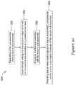
- An illustrative methodmay include displaying a first selectable option of an HVAC controller in a first region of a display of the HVAC controller, where the first region may have an array of pixels arranged in a plurality of rows and a plurality of columns for displaying an image in a dot matrix format.
- the methodmay include accepting an input from a user and in response to accepting the input from the user, animating the first selectable option and displaying a second selectable option.
- the methodmay include accepting a further input from a user.
- FIG. 1is a perspective view of an illustrative thermostat assembly
- FIG. 2is a bottom view of the illustrative thermostat assembly of FIG. 1 ;
- FIG. 3is a right side view of the illustrative thermostat assembly of FIG. 1 ;
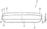
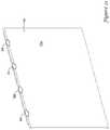
- FIG. 4is a left side view of the illustrative thermostat assembly of FIG. 1 ;
- FIG. 5is a top view of the illustrative thermostat assembly of FIG. 1 ;
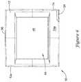
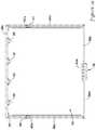
- FIG. 6is a front view of the illustrative thermostat assembly of FIG. 1 ;
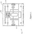
- FIG. 7is a back view of the illustrative thermostat assembly of FIG. 1 ;
- FIG. 8is a perspective view of a first sub-assembly hingedly opened from a second sub-assembly of the illustrative thermostat assembly of FIG. 1 ;
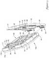
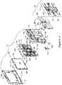
- FIG. 9is an exploded perspective view of the first sub-assembly of FIG. 8 separated from the second sub-assembly;
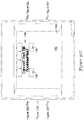
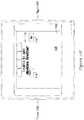
- FIG. 10is an exploded front view of the illustrative thermostat assembly of FIGS. 1-9 ;
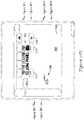
- FIG. 11is an exploded back view of the illustrative thermostat assembly of FIGS. 1-9 ;
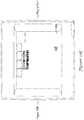
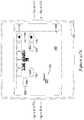
- FIG. 12is a schematic front view of a wall plate sub-assembly of the illustrative thermostat assembly of FIGS. 10-11 ;
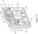
- FIG. 13is perspective back view of a sub-assembly of an illustrative thermostat assembly of FIGS. 10-11 ;
- FIG. 14is a schematic exploded view of the back of a housing or enclosure and the printed circuit board of the illustrative thermostat assembly of FIGS. 1-13 ;
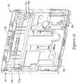
- FIG. 15is a perspective view the back of the housing or enclosure of the illustrative thermostat assembly of FIGS. 1-13 ;
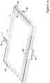
- FIG. 16is an exploded perspective view of an illustrative display sub-assembly
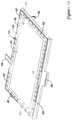
- FIG. 17is a perspective view showing features of the illustrative display sub-assembly of FIG. 16 ;
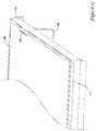
- FIG. 18is a front view of an illustrative frame of the illustrative display sub-assembly
- FIG. 19is a back view of the illustrative frame of the illustrative display sub-assembly
- FIG. 20is a perspective partial back view of the illustrative frame of the illustrative display sub-assembly
- FIG. 21is a perspective front view of an illustrative light guide plate of the illustrative display sub-assembly
- FIG. 22is a perspective back view of the illustrative guide plate of the illustrative display sub-assembly
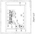
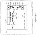
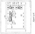
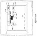
- FIGS. 23-28are perspective top views of different displays mounted in the frame of the illustrative display assembly
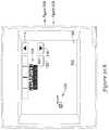
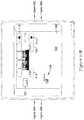
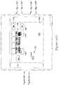
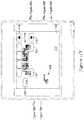
- FIG. 29is a schematic diagram for an illustrative thermostat assembly that is set the wiring terminals of the thermostat assembly to a safe state when a main thermostat sub-assembly is removed from a wall plate sub-assembly;
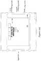
- FIG. 30is a flow diagram of an illustrative method of operating a thermostat assembly
- FIG. 31is a schematic flow diagram of an enrollment scheme for an illustrative thermostat
- FIGS. 32A-32AAare schematic diagrams showing an initial setup process for an illustrative thermostat
- FIG. 33shows an illustrative home screen for display on the display panel of an illustrative thermostat
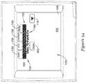
- FIG. 34shows an illustrative menu screen
- FIGS. 35-36show an illustrative dealer information entry screen
- FIG. 37show an illustrative password entry screen
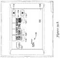
- FIG. 38show an illustrative installer menu screen
- FIGS. 39A-39Dshow illustrative sensor setup screens
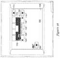
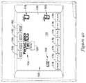
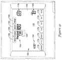
- FIGS. 40-43show illustrative view schedule screens
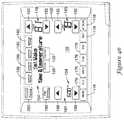
- FIG. 44-46show illustrative edit schedule screens
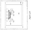
- FIGS. 47A-47Ushow illustrative edit schedule screens that use an illustrative scheduling assistant routine
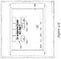
- FIG. 48show an illustrative saving changes screen
- FIGS. 49A-49Gshow illustrative weather screens.
- a thermostat 10 or other electronic assemblymay have a first sub-assembly 14 (e.g., a thermostat body or other sub-assembly) with a housing (e.g., a first housing) and a second sub-assembly 16 (e.g., a wall plate sub-assembly or other sub-assembly) with a housing (e.g., a second housing), where the first sub-assembly 14 and/or the second sub-assembly 16 may be provided individually or in combination.
- a first sub-assembly 14e.g., a thermostat body or other sub-assembly
- a second sub-assembly 16e.g., a wall plate sub-assembly or other sub-assembly
- the first sub-assembly 14 and/or the second sub-assembly 16may be provided individually or in combination.
- the second sub-assembly 16may be capable of being mounted on a wall with one or more connectors (e.g., threaded connectors or other connectors, as desired).
- the first sub-assembly 14may connect or otherwise be adjustably fixed with respect to the second sub-assembly 16 .
- the first sub-assembly 14may have extensions 26 capable of engaging openings 28 of the second sub-assembly 16 in a separable manner.
- the extensions 26 and the openings 28may engage one another (e.g., at a bottom of the thermostat 10 ) to create a hinge mechanism capable of supporting the first sub-assembly in an opened position and, optionally, without any further connecting features, as best shown in FIGS. 8 and 9 .
- the formed hinge mechanismmay have a kinematic backstop 29 and a release button or latch.
- the formed hinge mechanism with a kinematic backstop 29may omit the button or latch and may be readily separable by lifting up on the first sub-assembly 14 , as best shown in FIGS. 8 and 9 .
- an enclosure 12may house features of only the first sub-assembly 14 , only features of the second sub-assembly 16 , or features of the first sub-assembly 14 and features of the second sub-assembly 16 .
- the enclosure 12may include various latches, extensions, openings, hinges, button, and/or other connecting features that may facilitate connecting or snap together various portions of the enclosure 12 without the need for a separate fastener (e.g., a threaded member such as screw, bolt or other fastener).
- a separate fastenere.g., a threaded member such as screw, bolt or other fastener
- one or more separate fastenerse.g., a threaded fastener
- first sub-assembly 14may have a button 36 with a latch 37 , as best shown in FIGS. 8 and 9 , where the latch 37 may engage the second sub-assembly 16 and the button 36 may be pressed to release the connection between the latch 37 and the second sub-assembly 16 .
- the enclosure 12may be formed to provide a visually thin or minimalist appearance, as best shown in FIGS. 1-7 .
- the thermostatwhen the thermostat 10 is mounted to a wall or other structure, the thermostat may have one or more outer side walls that taper inward and toward the wall or other structure to which the thermostat 10 is mounted. This taper may help create the illusion that the thermostat 10 is thinner than it actually is.
- the enclosure 12may include an indicator 34 that may be viewable from a first side 14 a of the first sub-assembly 14 (e.g., where the first sub-assembly 14 has a first side 14 a and a second side 14 b ), as best shown in FIGS. 1-3 and 6 .
- the indicator 34may be a warning light, an indicator light indicating an alert is ready to be view, or any other type of light or indicator.
- the indicator 34may include a semi-transparent plastic material covering a light source (e.g., one or more lights such as an LED) that in some cases may be capable of changing colors.
- the lightmay be electrically and/or mechanically connected to a first PCB or PWB 19 that is within the enclosure 12 .
- the enclosure 12may provide one or more features that may capture and/or locate the first PCB or PWB 19 , a second PCB or PWB 20 , and/or other features of the first sub-assembly 14 and/or the second sub-assembly 16 .
- one or more projections 50may extend from the interior of the enclosure 12 , as best shown in FIG.
- the enclosure 12may be made from any material and by any process, as desired.
- the enclosure materialmay be injection molded with high impact polystyrene, acrylic-plexiglass, and/or any other material.
- the first sub-assembly 14may include a housing 13 (e.g., a first housing) of the enclosure 12 (e.g., a plastic housing 13 having a cover 13 a and a back 13 b or a housing 13 made from any other material and/or with any number of separable parts, if any) and a display sub-assembly 24 (e.g., a touch screen display) that may be positionable substantially within the housing 13 .
- the housing 13may house a processor or controller, a battery compartment 70 , a battery power input, a wired power port, wired control port, a wireless interface, and/or any other suitable components.
- the housing 13may house a first printed circuit board (PCB) or first printed wiring board (PWB) 19 where the cover 13 a may be positioned adjacent a first side 19 a of the first PCB or PWB 19 , and the back 13 b may be positioned adjacent a second side 19 b of the first PCB or PWB 19 .
- the second sub-assembly 16may be configured to be releasably secured to the first sub-assembly 14 adjacent to the back 13 b of the housing 13 of the first sub-assembly 14 .
- a wired power portmay be capable of receiving power from an optional external wired power source to power the thermostat 10 .
- a battery power inputmay be capable of receiving power from an optional battery in a battery compartment to power the thermostat 10 .
- the battery power inputwill optionally or automatically cease drawing power from the optional battery when the wired control port senses power from a wired power source.
- the battery power inputmay be capable of optionally or automatically receiving power from the optional battery inserted into the battery compartment 70 when it is sensed that the wired power port is not receiving power from a wired power source.
- the processor or controllermay be capable of determining from which power source power is drawn and/or may be utilized to set optional, customizable, or automatic power draw settings.
- the processor or controllermay be configured to operate under one or more power configurations.
- the processor or controllermay be capable of operating by receiving power form only the battery power input, receiving power from only the wired power port, or receiving power from the battery power input and the wired power port.
- the processor or controllermay be capable of generating one or more control signals configured to be sent to one or more HVAC components in communication with the thermostat 10 via a wired or wireless interface.
- a wireless interfacemay be capable of optionally wirelessly connecting the thermostat 10 directly or indirectly to the one or more HVAC components, and may be capable of providing the control signals generated by the processor or controller to the one or more HVAC components via the wireless interface.
- a wired control portmay be capable of optionally connecting the thermostat 10 directly or indirectly to one or more HVAC components via one or more wires, and may be capable of providing the control signals generated by the controller to the one or more HVAC components via the one or more wires.
- the processor or controllermay be configured to operate under one or more control configuration.
- the processor or controllermay be capable of controlling one or more HVAC component using only the wired control port, using only the wireless interface, or using the wired control port and the wireless interface.
- the wireless interface and/or the wired control portmay be optionally simultaneously or alternatively selected for communicating control signals to HVAC components in communication with the thermostat 10 .
- the first PCB or PWB 19may have any shape or size, as desired.
- the first PCB or PWB 19may have a portion 38 that is configured to receive a memory card connector 40 , as best shown in FIG. 11 .
- the portion 38 of the first PCB or PWB 19 that is configured to receive a memory card connector 40may have a perimeter that extends (e.g., juts out) from a main portion of the PCB or PWB 19 .
- such extension of the PCB or PWB 19may facilitate ESD protection of the board (and electronic components mounted on the board) while allowing for the thermostat 10 to receive an external memory card 41 .
- the second sub-assembly 16may be a wall plate 18 , and may include a second PCB or PWB 20 with electronic components 22 (e.g., terminal blocks 33 , relays, latching relays, etc., of which only a few are illustratively labeled in the Figures) and/or other features or components.
- electronic components 22e.g., terminal blocks 33 , relays, latching relays, etc., of which only a few are illustratively labeled in the Figures
- one or more wires from a building conditioning systeme.g., a heating, ventilation, and air conditioning (HVAC) system
- HVACheating, ventilation, and air conditioning
- the wall plate 18may facilitate securing the second PCB or PWB 20 therein in a floating manner. For example, a lateral space or gap may be formed between an edge of the second PCB or PWB 20 and the wall plate 18 .
- the floating connection between the wall plate 18 and the second PCB or PWB 20may facilitate inter-board connection (e.g., with the first PCB or PWB 19 ) during an installation procedure, such as when connecting the first sub-assembly 14 and the second sub-assembly 16 (e.g., through an electrical connection and/or mechanical connection).
- the first PCB or PWB 19 and the second PCB or PWB 20may structurally complement one another.
- electronic components 22may extend from the first PCB or PWB 19 and/or from the second PCB or PWB by varying distances toward the other PCB or PWB.
- the electronic components 22may arranged on each of the PCB or PWB 19 , 20 such that the electronic components 22 that extend a relatively far distance from one of the PCB or PWB 19 , 20 are aligned with either no electronic component of the other PCB or PWB 19 , 20 , or are aligned with an electronic components 22 that extends a relatively short distance from the other PCB or PWB 19 , 20 .
- the first side 19 a of the first PCB or PWB 19may face the second PCB or PWB 20
- the second side 19 bmay face away from the second PCB or PWB 20
- the second PCB or PWB 20may include a first side 20 a that faces the first PCB or PWB 19 , and a second side 20 b that faces away from the first PCB or PWB 19 , such that the first side 19 a of the first PCB or PWB 19 is spaced from the first side 20 a of the second PCB or PWB 20 by a spacing when the first PCB or PWB 19 is releasably engaged relative to the second PCB or PWB 20 via the first sub-assembly 14 and the second sub-assembly 16 .
- one or more componentmay be complementarily mounted to each of the first side 19 a of the first PCB or PWB 19 and the first side 20 a of the second PCB or PWB 20 .
- a component mounted on the first side 19 a of the first PCB or PWB 19may extend a first distance from the first PCB or PWB 19 toward the second PCB or PWB 20
- a component mounted on the first side 20 a of the second PCB or PWB 20may extend a second distance from the second PCB or PWB 20 toward the first PCB or PWB 19 when the first sub-assembly 14 is releasably engaged with the second sub-assembly 16 .
- the sum of the first distance and the second distancemay be greater than a distance of the spacing between the first PCB or PWB 19 and the second PCB or PWB 20 .
- the one or more components mounted to the first PCB or PWB 19 and the one or more components mounted to the second PCB or PWB 20may be laterally offset relative to one another. In other instances, taller components on the first PCB or PWB 19 may align with or overlap shorter components on the second PCB or PWB 20 to help provide a more compact and thinner overall profile.
- One or more of the components mounted on the PCBs or PWBs 19 , 20may include an inter-board connector 30 A- 30 B.
- the inter-board connector 30 Amay be mounted on the second PCB or PWB 20 , however, additionally or alternatively, the inter-board connector 30 B may be mounted on the first PCB or PWB 19 .
- the back 13 b of the housing 13may include one or more apertures 23 for accommodating the inter-board connectors 30 A- 30 B.
- the inter-board connectors 30 A- 30 Bmay carry one or more signals between the first PCB or PWB 19 and the second PCB or PWB 20 .
- the inter-board connectors 30 A- 30 Bmay be aligned and connected during connection of the first sub-assembly 14 with the second sub-assembly 16 , where such positioning may be facilitated by the hinge mechanism 32 and/or one or more other alignment features, as desired.
- the inter-board connector(s) 30 A- 30 Bmay be movable or adjustable (e.g., laterally movable or adjustable) up to a predetermined distance with respect to the first and/or second housing.
- Such an adjustable inter-board connector 30 A- 30 Bmay accommodate an amount of misalignment of the first PCB or PWB 19 and the second PCB or PWB 20 during connection of the first sub-assembly 14 with the second sub-assembly 16 .
- the PCB or PWB 19 , 20 to which the inter-board connector 30 AB is mountedmay be movable with respect to the housing of the sub-assembly 16 in which it is secured.
- such adjustability up to a predetermined distance of the inter-board connector 30 A- 30 B and the PCB or PWB 19 , 20may be built into tolerances of the connection of the PCB or PWB 19 , 20 with the respective housing, such as shown illustratively by gap 25 in FIG. 12 .
- the PCB or PWB 19 , 20and thus the inter-board connector 30 A- 30 B, may be movable so as to better accommodate misalignment of the first PCB or PWB 19 and the second PCB or PWB 20 during connection of the first sub-assembly 14 with the second sub-assembly 16 , while still being able to connect the inter-board connector 30 A- 30 B.
- the second PCB or PWB 20when provided, may be any shape or size capable of receiving the electronic components 22 , as desired.
- the second PCB or PWB 20may have a rectangular shape and a size (e.g., a surface area or other size) that is smaller than the first PCB or PWB 19 .
- the second PCB or PWB 20may be sized smaller than the first PCB or PWB 19 , where for example the first PCB or PWB 19 may extend laterally beyond one or more peripheral edges of the second PCB or PWB 20 in at least one direction to result in a non-overlapping region 27 , which may provide space to accommodate a battery assembly of the first sub-assembly 14 .
- the non-overlapping region of the first PCB or PWB 19may include one or more battery contacts 71 (e.g., battery terminals) to connect to one or more batteries, and/or an antenna.
- the batteriesWhen batteries are positioned within the battery contacts 71 , the batteries may extend away from the first side of the first PCB or PWB 19 toward the second housing of the wall plate 18 by a distance that may be greater than the spacing between the first PCB or PWB 19 and the second PCB or PWB 20 .
- the non-overlapping region 27 of the first PCB or PWB 19may include a first portion 27 a and a second portion 27 b (see FIG. 14 ).
- the first portion 27 a of the non-overlapping region 27may include or carry one or more batteries within the battery contacts 71 , as described above.
- the second portion 27 bmay include or carry a connector (e.g., a memory card connector 40 capable of receiving a memory card 41 and/or any other connector).
- the battery assemblymay include a battery compartment 70 that may be at least partially formed in the back 13 b of the housing 13 and may be configured to receive one or more batteries.
- the battery compartment 70may include the one or more battery contacts 71 extending therein from the first PCB or PWB 19 , and may form a cup shaped battery reservoir 72 that is capable of collecting leakage (e.g., leaked electrolytes) from one or more batteries that are inserted into the battery compartment 70 .
- the second sub-assembly 16may cover at least a portion (e.g., less than half, more than half, substantially all) of the battery assembly (e.g., the battery compartment 70 , the battery contacts 71 , and/or the battery reservoir 72 ).
- the wall plate 18may include one or more recesses 21 that are configured to accommodate at least part of the one or more batteries received in the battery assembly.
- the battery reservoir 72may be configured to collect leakage, if any, from one or more batteries that are received in the battery assembly, and allow it to pool therein without leaking outside the battery compartment, such as onto one or more electrical components of the first sub-assembly 14 and/or the second sub-assembly 16 .
- the battery contacts 71may extend from the first PCB or PWB 19 , through the back 13 b of the housing 13 and into the battery compartment 70 .
- the battery compartment 70may be positioned within the thermostat 10 such that it may be located on or adjacent a first side 19 a of the first PCB or PWB 19 , with a display 44 of the thermostat 10 positioned at or adjacent a second opposite side 19 b of the first PCB or PWB 19 .
- the battery reservoir 72may be defined by the battery compartment 70 and may be positioned below or at least partially below the battery contacts 71 when the first sub-assembly 14 is in an upright position.
- the battery reservoir 72may have one or more parts or members, and in some cases, may be formed unitarily with the enclosure 12 or may be added and/or connected to the enclosure 12 to collect leakage from the one or more batteries.
- the battery reservoir 72may be formed at least partially by a releasably securable insert 74 (see FIG. 13 ) that may be securable to the back 13 b of the housing 13 via an interference connection or any other type of connection. As best shown in FIG.
- clips 74 a , 74 b formed in the back 13 b of the housing 13may engage corresponding engagement members of the insert 74 to releasable secure the insert 74 to the back 13 b of the housing 13 via an interference connection.
- the battery reservoir 72may be entirely or at least partially unitary formed with the back 13 b of the housing 13 or other portion of the enclosure 12 , as desired.
- the battery reservoir 72 and/or the components thereofmay take on any shape configured to facilitate reception and maintenance of batteries therein.
- the battery reservoirmay be cup-shaped or other shape that is configured to collect leakage from one or more batteries inserted into the battery compartment 70 .
- the battery reservoir 72may provide space for the collection of battery leakage while preventing the leakage from affect sensitive parts and/or areas where such leakage could cause failure of the thermostat 10 .
- the battery reservoir 72may have a crescent, cup, or other shape that extends the length of the batteries, and in some cases, may be shaped much like a hollowed out canoe.
- the first sub-assembly 14may have a battery receptor 80 for receiving a battery 82 (e.g., a lithium ion battery or other battery).
- a battery 82e.g., a lithium ion battery or other battery.
- the battery receptor 80may be separable from the first sub-assembly 14 , as shown in FIG. 14 , to facilitate receiving and/or removing the battery 82 from the first sub-assembly.
- the battery receptor 80may be inserted into and/or at least partially removed from a side of the first sub-assembly 14 .
- the battery 82When the battery receptor 80 is inserted into the first sub-assembly 14 , the battery 82 may electrically contact and/or mechanically engage battery contacts such as battery contact 84 , which may be electrically and mechanically connected to the first PCB or PWB 19 . Such electrical contact between the battery 82 , the battery contacts 84 , and the first PCB or PWB 19 may facilitate powering one or more features of the thermostat 10 .
- the first sub-assembly 14may be powered with one or more received or connected batteries or other power sources (e.g., a first power source).
- the second sub-assembly 16may be powered with a wired connection to the power of a building (e.g., a second power source).
- the first sub-assembly 14may be powered by the same power source powering the second sub-assembly 16 through electronic connection(s) between the first sub-assembly 14 and the second sub-assembly 16 (e.g., the first power source and the second power source may be the same power source).
- the first sub-assembly 14 and the second sub-assembly 16may include electronic components 22 , which in some cases, may be sensitive to electrostatic discharges (ESDs).
- the first PCB or PWB 19 of the first sub-assembly 14may be protected from ESDs by the enclosure 12 and/or through conductors in or about the display 44 and/or touch screen 46 , as discussed further below.
- the second PCB or PWB 20 of the second sub-assembly 16may be protected from ESDs in a similar manner to the first PCB or PWB 19 and/or configured such that it is substantially insensitive to ESDs due to its remote positioning or location within the enclosure 12 with respect to portions of the thermostat 10 with which users typically interact.
- the second PCB or PWB 20includes electrical components that are not susceptible, or far less susceptible, to damage caused by ESD, such as terminal blocks, relays, etc.
- the first PCB or PWB 19may be positioned adjacent the back side 24 b of a display sub-assembly 24 (e.g., adjacent a reflective layer 45 , e.g. reflective foil or other reflective layer).
- the display sub-assembly 24e.g., a touch screen display
- the display sub-assembly 24may have a front side (e.g., a viewing side) 24 a and a back side (e.g., a non-viewing side) 24 b , as shown in FIG.
- conductive trace(s) 56may be in electrical connection with one or more tails 64 (e.g., a flexible electrical connector or any other type of connector) that may mechanically and/or electrically connect to the first PCB or PWB 19 (and/or the second PCB or PWB 20 ) to provide an electrical path from the conductive trace(s) 56 to a ground plane or other grounding feature of the PCB or PWB 19 , 20 .
- tails 64e.g., a flexible electrical connector or any other type of connector
- the conductive trace(s) 56may be configured to collect ESD entering between the front side 24 a of the display sub-assembly 24 and the housing 13 , and to deliver the collected ESD to the grounding plane or other grounding feature of the PCB or PWB 19 via the tail 64 or other electrical connector.
- the display sub-assembly 24may include, among other features, a backlight system 42 (e.g., including a backlight guide plate 43 for providing a backlight to the display 44 and a reflective layer 45 ), a display 44 (e.g., a liquid crystal display (LCD), a light emitting diode (LED) display, or other display), a touch screen 46 (e.g., an indium tin oxide (ITO) touch screen or other type of touch screen), and/or a frame 58 having connectors 48 for aligning and/or connecting features of the display sub-assembly 24 and/or mechanically connecting, releasably connecting, and/or removably fixing the display sub-assembly 24 to the first PCB or PWB 19 .
- the frame 58may include one or more protrusions capable of mating with concave features 54 of the backlight guide plate 43 .
- the display sub-assembly 24may include a touch screen 46 , a display 44 , a frame 58 , a backlight guide plate 43 , and a reflective layer 45
- the front side 24 amay be formed at least partially by the touch screen 46 and the back side 24 b may be formed at least partially by the reflective layer 45 .
- one or more of the features of the display sub-assembly 24 discussed herein or other features added to the display sub-assembly 24may form the front side 24 a and/or the back side 24 b thereof, as desired.
- the frame 58may be a plastic frame or other type of frame.
- the frame 58may include a front side 58 a , a back side 58 b , and side walls (e.g., top side wall 58 c , bottom side wall 58 d , and lateral side walls 58 e ) that may extend from the front side 58 a to the back side 58 b of the frame 58 and form a space 59 therewithin, as best shown in FIGS. 17 and 18 .
- the front side 58 a of the frame 58may face away from the first PCB or PWB 19 and the back side 58 b of the frame 58 may face toward the first PCB or PWB 19 .
- One or more of the side walls of the frame 58may include one or more reflective features 63 , where the reflective features 63 may be shaped to reflect and/or distribute incident light across at least part of the of the backlight guide plate 43 , the display 44 , and/or the touch screen 46 .
- the top side wall 58 c of the frame 58may include a plurality of reflective features 63 .
- the reflective features 63may be substantially equally, equally, or irregularly spaced across one or more sides of the display 44 and/or touch screen 46 when the display 44 and/or the touch screen 46 are positioned within the frame 58 to substantially equally spread light across the display and/or focus light on one or more particular locations, as desired.
- the reflective features 63may have any shape and/or may take on any configuration with respect to the frame 58 .
- the reflective features 63may be formed integrally with the frame 58 or may be separate features connected to the frame 58 .
- the reflective features 63may have a shape that directs reflected light in a particular manner.
- the reflective features 63may be at least partially cone-shaped and/or may be convex from a back side 58 b perspective to spread reflected light about one or more of the touch screen 46 , the display 44 , and/or the backlight guide plate 43 .
- the backlight guide plate 43may have a front side 43 a and a back side 43 b , as shown in FIGS. 21 and 22 .
- back side 43 b of the backlight guide plate 43may be affixed to the reflective layer 45 with adhesive and/or through other mechanisms.
- One or more recesses of the backlight guide plate 43may correspond or be in registration with one of the one or more reflective features 63 of the frame 58 .
- the one or more recessesmay have a shape that is configured to mate with a corresponding reflective feature 63 of the frame 58 such that light passing through the one or more recesses may be reflected and spread out by the reflective features 63 of the frame 58 .
- the backlight guide plate 43may allow light from one or more light sources 52 (e.g., light emitting diodes (LEDs), or other light sources connected to the first PCB or PWB 19 or other light features) to pass through one or more holes or openings 68 in the reflective layer 45 , where the holes or openings 68 may be in registration with the one or more recesses of the backlight guide plate 43 , so as to allow light from the one or more light sources 52 to reach the one or more recesses or concave features 54 of the backlight guide plate 43 .
- LEDslight emitting diodes
- Such light from light sources 52may be in registration with corresponding one or more protrusions 53 on the back side 43 b of the backlight guide plate 43 and/or one or more recesses (e.g., at least partially concave features 54 ) on the front side 43 a of the backlight guide plate 43 to focus light on optimized portions of reflective surfaces of the frame 58 , backlight guide plate 43 , and/or reflective layer 45 .
- one or more protrusions 53 on the back side 43 b of the backlight guide plate 43and/or one or more recesses (e.g., at least partially concave features 54 ) on the front side 43 a of the backlight guide plate 43 to focus light on optimized portions of reflective surfaces of the frame 58 , backlight guide plate 43 , and/or reflective layer 45 .
- the configuration of the backlight guide plate 43 in communication with light from the light sources 52may provide light to reflective features 63 of the frame 58 and/or incident light to one or more recesses of the backlight guide plate 43 from the corresponding reflective features 63 in order to distribute the incident light across the backlight guide plate 43 , the display 44 , and/or the touch screen 46 .
- the lightis distributed across the display such that the display appears to have an even brightness across the display.
- the display 44 , the backlight guide plate 43 , and/or the touch screen 46may be positioned at least partially within the frame 58 .
- the display 44 , the backlight guide plate 43 , and/or the touch screen 46may be at least partially positioned within the space 59 defined by the frame 58 .
- one or more connectors 48as best shown in FIGS.
- the frame 58may stop the display 44 , the backlight guide plate 43 , and/or the touch screen 46 from sliding out of the back side 58 b and/or the front side 58 a of the frame 58 .
- the backlight guide plate 43may be positioned at least partially between the display 44 and the first PCB or PWB 19 .
- some of the features thereofmay be positioned in the following order (e.g., from front to back): the touch screen 46 (e.g., a touch screen module 46 ), the display 44 (e.g., a display module), the backlight guide plate 43 , and the reflective layer 45 , all secured relative to the frame 58 .
- the frame 58may then secure the display sub-assembly 24 to the first PCB or PWB 19 .
- one or more connectors 48 of the frame 58e.g., one or more first interference tabs 48 a , as best shown in FIGS. 16, 19, and 18 , on the front side 58 a and/or the back side 58 b of the frame
- the one or more connectors 48may releasably engage the first PCB or PWB 19 through any type of connection including an interference connection where the connectors 48 extend through an opening or hole in the first PCB or PWB 19 to make a releasable connection and/or through any other type of suitable connection.
- the first sub-assembly 14may be assembled according to an illustrative method.
- a display 44 , a touch screen 46 , and/or a backlight guide plate 43may be connected to the frame 58 with an interference connection or any other type of connection using one or more connectors 48 (e.g., interfering tabs 48 b or other connectors on the back side 58 b of the frame 58 ).
- an interference connectionmay be a snap connection.
- the backlight guide plate 43may be positioned behind (e.g., toward the back side 58 b of the frame 58 ) the display 44 .
- the methodmay further include connecting the frame to the first PCB or PWB 19 using an interference connection with one or more connectors (e.g., interfering tabs 48 a or any other connectors), such that the backlight guide plate 43 is adjacent to the first PCB or PWB 19 , and such that one or more of the reflective features 63 of the frame may align with a corresponding light source 52 on the first PCB or PWB 19 .
- one or more connectorse.g., interfering tabs 48 a or any other connectors
- the touch screen 46 and/or the display 44 of the display sub-assembly 24may be secured within the enclosure 12 (e.g., within housing 13 ), as shown for example in FIG. 11 , such that an ESD may have a path to a ground pad or grounding feature of the first PCB or PWB 19 , such that the ESD does not negatively affect (e.g. damage) the display 44 or other components.
- a conductive trace 56 along, adjacent, or parallel to a perimeter of a touch screen 46 of the display sub-assembly 24may provide a path for the ESD from the touch screen 46 or other feature to a grounding feature.
- the conductive trace 56may extend adjacent or along and spaced from a perimeter of the aperture 15 in the housing that exposes at least part of the front side 24 a of the display sub-assembly 24 for viewing by a user.
- the conductive trace 56may be positioned on the first side 24 a of the display sub-assembly 24 between the first side 24 a and the housing 13 (e.g., the cover 13 a of the housing 13 ).
- the touch screen 46may include a conductive trace 56 at, around, adjacent to, spaced from, and/or parallel to a perimeter of the touch screen 46 , as best shown in FIGS. 23-28 .
- the conductive trace 56may form a complete loop (e.g., a closed loop) or may include one or more gaps therein so as to not form a closed loop.
- the conductive trace 56may form a closed loop or non-closed loop and may be disposed on or adjacent the front side 24 a of the display sub-assembly 24 , where the conductive trace 56 may be disposed at, around, adjacent to, inward from, and/or parallel to the perimeter of the touch screen 46 forming the first side of the display sub-assembly 24 .
- the conductive trace 56is added on top of the touch screen 46 , where new wires or traces 65 on a tail 64 connect the conductive trace 56 to a ground plane or ground feature on the first PCB or PWB 19 .
- the conductive trace 56may be added to the display sub-assembly in any other manner.
- the conductive trace 56is connected to one of the existing wires on the tail 64 .
- the conductive trace(s) 56may be spaced inward from an outer edge of the touch screen 46 of the display sub-assembly 24 , as shown.
- the conductive trace(s) 56may be implemented in one or more of several different manners to effectively provide a path for the ESD to a grounding feature of or on the PCB or PWB 19 , 20 .
- the conductive trace(s) 56may extend to an edge of the display 44 (see FIG.
- strips 60 of a conductive materialmay be applied to the touch screen 46 that are, or are electrically connected to, the conductive traces 56 and extend to an edge of the touch screen 46 (e.g., thin strips that may be spaced approximately 0.2 inches apart and have a width of 0.02 inches, or other strips configured in any manner as desired) (e.g. see FIG. 26 ), openings or holes 61 may be placed in the conductive trace (e.g., holes spaced approximately 0.1 inches, 0.2 inches, 0.3 inches, or any other distance apart and having a diameter of approximate 0.01 inches, 0.02 inches, 0.03 inches, 0.04 inches, 0.05 inches, or any other diameter) (e.g. see FIG.
- one or more portions 57 (represented by the hashed lines in FIG. 28 ) of a foil layer 62 of the touch screen 46may be removed from the edge of the touch screen 46 to an outer edge of the conductive trace(s) 56 (e.g., the foil layer 62 may be cut and removed from the touch screen 46 ) (see FIG. 28 ), and/or any other configuration may be utilized to use the conductive traces 56 and the tail(s) 64 connected thereto to provide an electrical path to a ground feature of one or more of the first PCB or PWB 19 and the second PCB or PWB 20 .
- the conductive trace 56may have a first portion 56 a and a second portion 56 b , where the first portion 56 a may extend substantially or entirely around the front side 24 a of the display sub-assembly 24 (e.g., at or spaced from the outer edge or perimeter of the display sub-assembly 24 ).
- the second portion 56 b of the conductive trace 56may include a plurality of strips 60 spaced from one another and extending from the first portion 56 a of the conductive trace 56 toward and/or to the outer edge or perimeter of the display sub-assembly 24 (e.g., the outer edge or perimeter of the touch screen 46 or other feature of the display sub-assembly 24 ).
- a conductive trace 56may be provided on a front side 24 a of the display sub-assembly 24 (e.g., the touch screen 46 ) adjacent a perimeter of the display sub-assembly 24 .
- the first PCB or PWB 19may be positioned adjacent the back side 24 b of the display sub-assembly 24 and the conductive trace 56 may be electrically connected to a grounding feature of the first PCB or PWB 19 via an electrical connector (e.g., at tail 64 ).
- the methodmay include mechanically connecting and/or removably fixing the display sub-assembly 24 to the first PCB or PWB 19 .
- the touch screen 46 , the display 44 , the reflective layer 45 , and the backlight guide plate 43may be removably fixed within the frame 58 via connectors 48 and/or other connectors.
- the display sub-assembly 24 and the frame 58may then be removably fixed to the first PCB or PWB 19 via connectors 48 , tail 64 , and/or other connectors to form a connection and an electrical ESD path between the display sub-assembly 24 and the first PCB or PWB 19 .
- the thermostat 10may be configured to be used with virtually all heating and cooling systems for both residential and commercial applications. Additionally, or alternatively, the thermostat 10 may be capable of working with one or more accessories (e.g., RedLINKTM accessories or any other accessory), which may allow contractors to reduce inventory costs and/or realize other business advantages. In some instances, the thermostat 10 may be wired directly to, wired indirectly to, and/or wirelessly connected to the accessories and/or power sources.
- the thermostat 10may be wired directly to, wired indirectly to, and/or wirelessly connected to the accessories and/or power sources.
- the thermostat 10may be powered at least in part by using one or more batteries (e.g., lithium ion batteries, AA batteries, AAA batteries, etc.), alternating current (AC), and/or direct current (DC).
- batteriese.g., lithium ion batteries, AA batteries, AAA batteries, etc.
- ACalternating current
- DCdirect current
- the thermostat 10may be battery powered, it may additionally, or alternatively, be wired for power, as referred to above.
- the thermostat 10may have a direct or indirect wired or wireless connection to HVAC equipment in a non-zoned HVAC system and can be powered with two (2) wires (e.g., a power or hot wire and a common wire) or by battery only.
- the thermostat 10may have a direct or indirect wired or wireless connection to HVAC equipment in a zoned HVAC system and can be powered with two (2) wires (e.g., a power or hot wire and a common wire) or by battery only.
- the thermostat 10may work with an equipment interface module (EMI) where one or more pieces of HVAC equipment and/or accessories may have a wired and/or wireless connection to the EIM, while the thermostat 10 is powered with two wires (e.g., a power or hot wire and a common wire) or by battery only (e.g., for a completely wireless thermostat or for other reasons).
- EMIequipment interface module
- the thermostat 10may work with a TrueZONETM wireless adapter or other wireless adaptor where one or more pieces of HVAC equipment and/or accessories may have a wired or wireless connection to a TrueZONETM panel or other zone panel such that the thermostat may control a zone panel via a wireless adapter, while the thermostat 10 may be powered with two (2) wires (e.g., a power or hot wire and a common wire) or by battery only (e.g., for a completely wireless thermostat or for other reasons).
- the processor or controller of the thermostat 10may be programmable to send control signals for HVAC components through the EIM, the wireless adapter, the zone panel and/or directly or otherwise indirectly to one or more of the HVAC components.
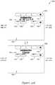
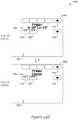
- latching relaysmay be used to provide control signals from the thermostat 10 and to an HVAC system or the like. Due to their relatively low power consumption, latching relays may be particularly useful when the thermostat 10 is battery powered. Latching relays, however, remain in their last state (latched state) until power is applied to switch the state. Thus, without proper control, the latching relays will tend to stay in their previous latched state when battery (or other) power is disconnected, and/or when becoming disconnected from a controlling microcontroller. This can cause an HVAC system to remain in a non-desirable state if either of these conditions occurs.
- the second sub-assembly 16may include a second PCB or PWB 20 with electronic components 22 (e.g., terminal blocks 33 , relays, latching relays, etc., of which only a few are illustratively labeled in the Figures) and/or other features or components.
- electronic components 22e.g., terminal blocks 33 , relays, latching relays, etc., of which only a few are illustratively labeled in the Figures
- one or more wires from a building conditioning systeme.g., a heating, ventilation, and air conditioning (HVAC) system
- HVACheating, ventilation, and air conditioning
- a microcontroller of the first PCB or PWB 19may generate control signals to control the state of one or more latching relays on the second PCB or PWB 20 .
- the one or more latching relaysmay then provide a corresponding control signal to the HVAC system via wires connected to the terminal blocks 33 . If power is disconnected, and/or if the first sub-assembly 14 is separated from the second sub-assembly 16 , the latching relays will remain in their previous latched state. This can be undesirable. For example, if the previous latched state corresponds to a furnace “on” state, the furnace will remain “on” until power is restored, and/or until the first sub-assembly 14 is reconnected to the second sub-assembly 16 , regardless of the temperature in the building. This can waste energy, create uncomfortable conditions, and in some cases, can cause damage.
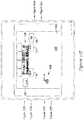
- latching relaysmay be connected to a microprocessor or microcontroller 69 of a thermostat 10 , such that a position (e.g., an opened position or a closed position or other position) of the latching relays may be controlled by the microprocessor or microcontroller 69 .
- a positione.g., an opened position or a closed position or other position
- the microprocessor or microcontroller 69At times (e.g., when dismounting a portion of the thermostat), it may be desirable to separate the microprocessor portion (first portion 76 ) of the thermostat 10 from the other portion (e.g., second portion 78 ) that includes the latching relays. As noted above, this can cause the latching relays to be left in an undesirable or improper position.
- the microcontroller 69 and/or other processors of the first portion 76 of the thermostat 10may be located on the first PWB or PCB 19 having a first set of circuitry thereon to which the microcontroller 69 may be connected.
- the second portion 78 of the thermostat 10may include the second PWB or PCB 20 secured relative to a second housing 17 of the second sub-assembly 16 , where the second portion 78 of the thermostat 10 may be releasably securable to the first portion 76 of the thermostat 10 .
- the second PWB or PCB 20may include a second set of circuitry (e.g., circuitry that may or may not include ESD sensitive components, but does include at least one or more relays, one or more capacitors, and/or one or more terminal blocks 33 ) capable of being powered by a power source V DD (e.g., wired power, batteries, etc.), and configured to receive one or more control signals from the first PWB or PCB 19 when the second portion 78 is releasably engaged with the first portion 76 .
- the second PWB or PCB 20may also provide one or more corresponding control signals to the one or more output terminals of the second portion 78 for control of one or more HVAC component in communication with the thermostat 10 .
- the circuitry of the second PWB or PCB 20may be configured to set one or more output terminals of the second portion 78 to a predetermined state when the first portion 76 is released and/or at least partially disengaged from the second portion 78 (e.g., disengage electrical communication from the first PWB or PCB 19 to the second PWB or PCB 20 ).
- the circuitry of the second PWB or PCB 20will automatically set the output terminals of the second portion 78 to a predetermined state when the first sub-assembly 14 ceases electrical communication with (e.g., is released and/or at least partially disengaged from) the second sub-assembly 16 .
- latching relays 79which may be located on the second PCB or PWB 20 of the second sub-assembly 16 , may be properly configured (e.g., configured to set the output terminals to the predetermined state) when separated from a microprocessor or microcontroller 69 or the like (e.g., when the first sub-assembly 14 is separated from the second sub-assembly 16 ).
- the configuration of the latching relays 79may be controlled by the microcontroller 69 , and when the first portion 76 and the second portion 78 become disengaged, the configuration of the latching relays 79 may be set by circuitry on the second portion 78 .
- pre-set logic levels on a control bus or on appropriate terminalsmay position the one or more latching relays 79 into a configuration that provides one or more corresponding control signals to the one or more output terminals of the second portion 78 .
- thismay be accomplished through the use of one or more pull-down resistors 85 and/or one or more pull-up resistors 77 of the second set of circuitry on the second PWB or PCB 20 .
- the approach used to properly position the latching relays 79 when the first portion 76 is disengaged from the second portion 78e.g., position the latching relays 79 so as to turn off connected external devices or position the latching relays 79 in any other predetermined manner
- the systemmay include two pull-down resistors 85 and one pull-up resistor 77 , or other configurations of resistors and/or electrical components capable of positioning the latching relays in a predetermined position so as to turn off connected external devices when the first portion 76 is at least partially electrically disconnected from the second portion 78 .
- the logic levels on a control bus 73 or other terminalsmay no longer be set by the microcontroller 69 as they would be when the first portion 76 of the thermostat 10 is in electrical communication with the second portion 78 of the thermostat 10 .
- the logic levelsmay be automatically controlled by the pull-down resistor(s) 85 and/or the pull-up resistor(s) 77 in the absence of the control signals from the microcontroller 69 .
- the current through the relay coils of the latching relays 79may automatically flow according to predetermined logic levels in an appropriate direction to set the state of the latching relays 79 such that all of the external devices (e.g. external device 83 ) are switched off.
- the particular state (off/on) for any particularly relaymay be programmed by choosing an appropriate pull-up or pull-down resistor configuration.
- the configuration utilizing pull-down resistors and pull-up resistor(s)may allow for the elimination of an auxiliary driving circuit, such as a microcontroller, a logic array, etc.
- Inputs to a first part (e.g., a first terminal) and/or a second part (e.g., a second terminal) of the coils 75may be operatively coupled to corresponding one or more control signals from the first set of circuitry of the first portion 76 of the thermostat 10 (e.g., from the microcontroller 69 of the first portion 76 ) when the first portion 76 and the second portion 78 are engaged (e.g., are electrically communicating).
- Inputs to the first terminal of the coils 75may be pulled up by the pull-down resistors 85 through an operative coupling (e.g. inverter) therewith to VDD when the first portion 76 of the thermostat 10 is electrically disengaged from the second portion 78 of the thermostat 10 .
- Inputs to the second terminal of the coils 75may be pulled down by a pull-up resistor 77 and a power supply V dd through an operative coupling (e.g. inverter) therewith when the first portion 76 of the thermostat 10 is electrically disengaged from the second portion 78 of the thermostat 10 .
- a pull-up resistor 77which includes a microcontroller 69 or other controller, is electrically separated from second portion 78 of the thermostat 10 (e.g., electrically separated)
- the logic levels at the control bus 73 of the second portion 78 of the thermostat 10may be automatically defined by the pull-down resistors 85 , and the pull-up resistor 77 through the operative couplings (e.g. inverters).
- a capacitor or other power storage device 91may be used to provide power to the second portion 78 of the thermostat 10 for a relatively short duration (e.g. less than 1 hour, less than 10 minutes, less than 1 minute, less than 1 second, etc). During this relatively short duration, the latching relays 79 may be set to a state that turns off all external devices 83 . Once the latching relays 79 are latched into an appropriate state, power from the power storage device 91 may no longer be needed.
- the power storage device 91may be a capacitor, battery or any other power storage device, as desired.
- this circuit arrangement on second portion 78 of the thermostat 10may allow for a simple, reliable, and low cost solution to controlling the state of the relays when the first portion 76 of the thermostat 10 having a microcontroller 69 or other controller is separated from the second portion 78 of the thermostat 10 that includes latching relays.
- FIG. 30is an illustrative method.
- the first sub-assembly 14may be separated (e.g., electrically separated) from the second sub-assembly 16 , as shown at 302 .
- the second sub-assembly 16may include one or more output terminals connected to one or more external devices (e.g., a furnace, an air conditioning unit, a humidifier, a dehumidifier, etc.).
- one or more output terminals of the second sub-assembly 16may be automatically set to a predetermined state, as shown at 304 .
- the output terminals of the second sub-assembly 16may be automatically set to a predetermined state (e.g., such that connected external devices are turned off) by automatically setting one or more latching relays 79 of the second sub-assembly 16 to the predetermined state, where the latching relays 79 are otherwise controlled with control signals from the first sub-assembly 14 when the first sub-assembly 14 and the second sub-assembly 16 are releasably engaged or otherwise in electrical communication with each other.
- a predetermined statee.g., such that connected external devices are turned off
- the first sub-assembly 14 and the second sub-assembly 16may be reengaged 306 such that one or more control signals from first sub-assembly 14 may be provided 308 to the second sub-assembly 16 .
- the one or more control signalsmay cause the second sub-assembly 16 to provide one or more control signals to one or more external devices (e.g., HVAC components or other components) via the output terminals of the second sub-assembly 16 .
- one or more external devicese.g., HVAC components or other components
- the second side 20 b of the second PCB or PWB 20may include one or more test pads.
- the test pads of the second side 20 b of the second PCB or PWB 20may be connected and are suitable for performing functional tests of the microcontroller 69 and/or other circuitry of the first PCB or PWB 19 , and/or circuitry of the second PCB or PWB 20 , when the first sub-assembly 14 is releasably engaged with the second sub-assembly 16 .
- the display sub-assembly 24may create an interface display 100 on the display 44 , which a user may interact with in any manner, including, but not limited to, interacting with the interface display 100 through touching a screen, buttons adjacent to or on the interface display 100 , a remote device, and/or though some other interaction mechanisms.
- the interface display 100may be provided by a display 44 that has a 2-dimensional array of pixels that covers the full display area of the display 44 .
- the interface display 100may be provided by a display 44 that is a segmented display, which includes a plurality of predefined segments that can be switched on and off to give the appearance of desired characters, icons or other graphical features.
- the predefined segmentsare not arranged in a full 2-dimensional array of pixels that covers the full display area of the display 44 . Rather, at least some of the predefined segments are elongated, define a symbol or icon, or otherwise do not fall into a simple 2-dimensional array of pixels.
- the display 44may be any suitable display panel using any suitable display panel technology including, for example, Eidophor, Electroluminescent display (ELD), Electronic paper (E Ink, Gyricon), Light emitting diode display (LED), Cathode ray tube (CRT) (Monoscope), Liquid-crystal display (LCD) (TFT, LED, Blue Phase, IPS), Plasma display panel (PDP) (ALiS), Digital Light Processing (DLP), Liquid crystal on silicon (LCoS), Organic light-emitting diode (OLED) (AMOLED), Organic light-emitting transistor (OLET), Surface-conduction electron-emitter display (SED), Field emission display (FED), Laser TV (Quantum dot, Liquid crystal), MEMS display (IMoD, TMOS, DMS), Quantum dot display (QD-LED), Ferro liquid display (FLD), Thick-film dielectric electroluminescent technology (TDEL), Telescopic pixel display (TPD), Laser
- ELDElectro
- the display 44may be a segmented display that has predefined segments that: (1) define a 2-dimensional array of pixels in a first region or area 104 of the display 44 ; and (2) define segments of segmented characters, symbols or icons, or otherwise do not fall into a simple 2-dimensional array of pixels in a second region or area 102 of the display 44 .
- the first region or area 104may sometimes be referred to as a dot matrix display area
- the second region or area 102may be referred to as a fixed segment display area, even though in some cases the first region or area 104 may be formed from an array of fixed segments that are configured as a 2-dimensional array of fixed segment pixels.
- the first region or area 104may function as a message center that can be used to display text based messages, animations, and/or other information.
- the first region or area 104may be configured to only display two (2) lines of text, but this is just one example.
- the second region or area 102may encompass the remainder of the display 44 that is not part of the first region or area 04 .
- the display 44may be an LCD display panel, where each of the plurality of predefined segments in both the first region or area 104 and the second region or area 102 are each layed out on a substrate and independently controllable by the processor or controller of the first sub-assembly 14 .
- Such an LCD panelmay consume relatively low power (e.g. suitable for battery powered devices), and may be selectively backlit by the backlight system 42 of the display sub-assembly 24 .
- the one or more areasmay be controllable with software, firmware, and/or other computer executable instructions stored on a non-transitory computer readable medium of the thermostat 10 or other device that is capable of communicating with the thermostat 10 .
- the thermostat 10may include memory and/or a processor that is configured to save, record, and/or operate the software, firmware, or other computer executable instructions.
- the numerical indicatorse.g., first, second, third, etc. are meant for explanatory purposes only and are not meant to be limiting unless otherwise indicated.
- the numerical indicatorsmay are used for clarity purposes to distinguish between one feature relative to another and the numerical indicators may be switched.
- the message center(e.g., the first area 104 with a two (2) line dot matrix area) may be capable of displaying up to three full lines of text (e.g., three full lines of text or graphics, two full separate lines of text or graphics and up to two half or partial lines of text or graphics, two partial lines of text or graphics with one or more full lines of texts or graphics, etc.).
- the full and/or partial lines of text or graphicsmay be full or partial lines in the vertical and/or horizontal directions.
- the first area 104may simultaneously display in a vertical direction an integer number of options (e.g., on a full line of text or graphics) plus a fraction of an option (e.g., on a partial line of text or graphics, on about a half line of text or graphics, etc.).
- the first area 104 of the interface display 100may simultaneously display in a vertical direction two options on separate full lines of text plus a fraction of a third option on a partial line of text.
- the options discussed hereinmay include, but are not limited to, lists of options, selectable options, installer setup options, sensor control options, program scheduling options, programmable options, menu list items or options, questions or queries, informative messages, directions, alerts, warnings, logs, other options capable of being displayed on a message center, and/or any combinations thereof.
- Such displayable optionsmay be used together or separate and/or may viewed or obtained by selection of another option.
- programmable optionsmay be used to set settings of the thermostat 10 that may be used for controlling subsequent operation and/or functionality of the HVAC controller.
- selection of the options in the first area 104 of the interface display 100may allow a user to set or change a programmable option that may modify a subsequent operation and/or functionality of the thermostat 10 .
- subsequent operation and/or functionality of the HVAC controllermay include, among other features, where temperature and/or humidity is sensed, how temperature and/or humidity is sensed, a schedule for the HVAC components of the HVAC controller, etc.
- menu optionsmay be used to navigate to a menu that may allow a user to change an option that modifies subsequent operation and/or functionality of the thermostat 10 .
- the controller or processor of the thermostat 10may be programmed such that first area 104 of the user interface display 100 displays one or more captions in a first line of text and a check box or other toggle box or other feature in a second row above or below the row with the one or more captions.
- An option displayed in the first area 104 with a captionmay be selected by touching or pressing a button of the thermostat 10 and/or by touching an active touch area in the first area 104 of the user interface display 100 .
- the buttonmay be an defined button in the second area 102 , a hard button that is situated adjacent to the screen, or any other suitable button.
- the active touch area in the first area 104may be an active touch area associated with the displayed option and may take up the entire first area 104 or a portion of the first area 104 that is less than the entire first area 104 .
- a check box or toggle boxmay depict a selection has been made, for example, by displaying a check in a box, an X in a box, by filling in a box, and/or otherwise marking a box or about a box to indicate the displayed option has been selected.
- a previously selected boxmay be deselected by touching or pressing a button of the thermostat and/or by touching an active touch area of the first area 104 that is associated with the displayed option.
- Such a display of options with a check box or toggle boxmay be utilized for selection of days of the week, holidays, and/or vacation days for setting a schedule, for setting which air sensors to use for sensing environmental conditions, and/or for any other option which may be selected and/or deselected. This is just one example of how an option may be selected.
- the controller or processor of the thermostat 10may be programmed such that the message center (e.g., first area 104 ) may provide an instruction, a query, and/or a question or a sequence of instructions, queries, and/or questions (e.g., one or more queries or questions, two or more queries or questions, etc.) to a user viewing and/or using the message center. Additionally, or alternatively, the message center may be capable of accepting responses to queries and/or questions, which may be processed by the processor or controller of the thermostat 10 . Illustratively, responses may include a selection of a displayed option, entering text, and/or other responses in the first area 104 and/or the second area 102 of the interface display 100 , and/or via one or more hard buttons of the thermostat 10 .
- the message centere.g., first area 104
- the message centermay provide an instruction, a query, and/or a question or a sequence of instructions, queries, and/or questions (e.g., one or more queries or questions, two or
- the thermostat 10may configure the processor or controller to operate under one of the three control configurations discussed above, one or more of the two power configurations, and/or may configure the processor or controller of the thermostat 10 in one or more other manners.
- the questions or queries and/or the accepting of responses or answersmay be part of one or more setup processes or other processes to identify one or more HVAC components to be controlled by the thermostat, to identify one or more thermostat settings, to identify one or more configuration settings, to identify one or more power configurations, etc.
- Instructions, queries, and/or questionsmay be utilized for any purpose, for example, for setting up a schedule of operation for the thermostat.
- example instructions, queries, and/or questionsmay include, but are not limited to: SELECT DAYS WITH SAME SCHEDULE; PRESS NEXT AFTER SELECTING DAY. (e.g., after selecting a day, this new instruction may be displayed in the first area 104 ); IS SOMEONE HOME ALL DAY?
- NO OR YESe.g., where NO and YES may have separate associated active touch areas and/or may be selectable by selecting a button in communication with a processor or controller of the thermostat 10 ); WHEN DOES THE FIRST PERSON WAKE UP?; WHEN DOES THE LAST PERSON LEAVE?; WHEN DOES THE FIRST PERSON RETURN?; WHEN DOES THE LAST PERSON GO TO SLEEP?; SET YOUR WAKE TEMPERATURE; SET YOUR LEAVE TEMPERATURE; SCHEDULE YOUR FAN TOO?; WAKE FAN SETTING; LEAVE FAN SETTING; RETURN FAN SETTING; SLEEP FAN SETTING; SCHEDULE MORE DAYS?; REPEAT STEPS IF YOU WANT TO SCHEDULE MORE DAYS; REVIEW SCHEDULE?; SAVING CHANGES; and/or any other instructions, queries, and/or questions, as desired.
- the controller or processor of the thermostat 10may be programmed or otherwise configured to display one or more options of the thermostat 10 in the first area 104 of the interface display 100 for selection by a user (e.g., selectable options), as referred to above.
- the processor or controller of the thermostat 10may allow a user to select one or more options (e.g., select a single displayed option or select between two or more options, etc.), where the options may be displayed in the first area 104 of the thermostat 10 .
- the controller or processor of the thermostat 10may be configured to display less than all of the two or more options (e.g., display one line of an option and less than a full line of another option) in the first region of the display at any given time. Any of the options or items displayed in the first area 104 may be available for selection by a user by one or more of touching the option and interacting with one or more buttons.
- the controller or processor of the thermostat 10may be programmed or otherwise configured to animate one or more options or items displayed in the first area 104 .
- animated options or itemsmay include displayed options or items in the first area 104 that a user may scroll through.
- the options or itemsmay appear to move in a vertical, horizontal, or vertical and horizontal direction, and/or any combination thereof including diagonal directions.
- the options or itemsmay be animated in any manner, in some cases the animation of the one or more options or items may include incrementally moving the one or more options or items so that the one or more of the options or items appear to move in the first area 104 of the interface display.
- the first area 104 of the interface display 100may display an option on a full line of text (e.g., an integer option) therein and one or more options on one or more partial lines of text above and/or below the full line of text.
- a full line of texte.g., an integer option
- the presence of options listed on one or more partial lines of text above and/or below the full line of textmay indicate to the user that there are additional available options by scrolling up and/or down, respectively.
- a top of the listmay be indicated and further options may be displayed by scrolling down though the options.
- a bottom of the listmay be indicated and further options may be displayed by scrolling up though the options.
- the options or items displayed in the first area 104may be scrolled through (e.g., in a direction of a partial line of text) and/or selected by interacting with a button of the thermostat 10 and/or touching the interface display 100 and interacting with the touch screen 46 .
- interacting with and/or activation of a button of the thermostat 10may cause the controller or processor of the thermostat 10 to selectively animate one or more of the options or items displayed in the first area 104 .
- the button(s) of the thermostat 10may correspond to a physical button that may be offset from the interface display 100 and/or the button(s) of the thermostat 10 may correspond to a button region defined on the interface display 100 in one or more of the first area 104 and the second area 102 .
- the second area 102may include one or more predefined touch regions, where each touch region of the second area 102 may correspond to a different button of the thermostat 10 .
- selection of a buttone.g., an arrow 114 , 116 or other button
- the processor or controllermay highlight a different selectable option in the first region of the user interface display 100 and touching the button multiple times may cause the processor or controller to highlight another selectable option in the first area 104 of the user interface display 100 .
- the options or items displayed on the first area 104 of the interface display 100may be scrolled through and/or adjusted by touching the touch screen 46 .
- the processor or controllermay be configured to recognize when a user touches the interface display 100 and moves along the touch screen 46 (e.g., moves along the touch screen 46 in a swiping manner, such as a dragging or pushing motion).
- the two or more optionsmay be animated and/or scrolled through in a vertical and/or horizontal manner.
- the processor or controller of the thermostat 10may recognize swiping motions on the touch screen 46 within the first area 104 of the interface display 100 and may display one or more next screens in a sequence of screens (e.g., when setting a schedule, when setting up the thermostat, and/or when using other sequences of screens).
- the processor or controllermay be configured to accept a selection of a displayed option by detecting a user touch of the displayed selectable option via the touch screen 46 .
- the processor or controller of the thermostat 10may define an active touch area for each selectable option (e.g., touch selectable option) displayed on the display 44 of the thermostat 10 (e.g., a touch selectable option displayed on the first area 104 and/or the second area 102 of the interface display 100 ).
- the active touch area for each selectable optionmay or may not be viewable in normal use of the thermostat 10 .
- the processor or controllermay define an active touch area for each of the two or more selectable options such that if a user touches the interface display 100 within a defined active touch area the associated selectable option will be selected.
- the processor or controllermay highlight a selected selectable option in response to receiving a user touch within an active touch area and/or in response to receiving any other selection signal for a particular selectable option or set of options.
- the highlighted portion 165may represent the entirety of the active touch area associated with the selectable option, as best shown in FIG. 34 . Alternatively, the highlighted portion may not represent the entirety of the active touch area associated with the selectable option.
- the processor or controllermay be configured to highlight a selectable option response to receiving a first user touch at a position of the interface display 100 associated with a selectable option (e.g., within an active touch area) and then selecting the selectable option upon a second touch by a user or by a touch and hold by a user, where selecting the selectable option may include the thermostat 10 (e.g., the controller or processor thereof) performing an action associated with the selected selectable option.
- the thermostat 10e.g., the controller or processor thereof
- a first selectable optionmay be displayed in the first area 104 of the interface display 100 of the thermostat 10 .
- a usermay provide an input and the thermostat 10 may accept they input, where the input may correspond to interacting with the first selectable option.
- the controllermay animate the first selectable option (e.g. move horizontally or vertically off the screen) and animate a second selectable option (e.g. move horizontally or vertically onto the screen) in the first area 104 of the interface display 100 of the thermostat 10 .
- a usermay provide an input that relates to the second selectable option, and the controller or processor of the thermostat 10 may accept the input from the user and select the second selectable option.
- the second selectable optionmay be highlighted and/or a new display may be displayed in response to the selection of the second selectable option.
- an illustrative home screen 138may be displayed on the interface display 100 .
- several active touch and/or interactive featuresmay be displayed.
- a time 140a following schedule indicator 142 , a current temperature 144 , a current humidity 146 , a scheduled temperature 148 , temperature setting arrows 150 , a home button 152 , a fan button 154 , a system button 156 , a menu button 158 , and/or other active and/or interactive features may be displayed in the first area of the interface display 100 .
- the first area 104may be capable of displaying the active system (e.g., Heat, as shown for example in FIG. 32O ) and 33 , Cool, Auto, Off, and/or other system) currently being controlled by the thermostat 10 .
- the active systeme.g., Heat, as shown for example in FIG. 32O
- the interface display 100may include any number of fixed controls in the second area 102 to facilitate creating and/or modify text characters.
- the interface display 100may include 1, 2, 3, 4, 5, 6, 7, 8, 9, 10, etc. fixed controls in the second area 102 , as desired.
- the interface display 100may include six (6) fixed controls in the second area 102 , as shown in FIGS. 35 and 36 (e.g., with respect to a dealer name screen, but such fixed controls may be used with respect to other screens). The six (6) fixed controls in the second area 102 of FIG.
- 35-36may include, but are not limited to, a left arrow 134 and a right arrow 136 below the first area 104 to move within the text, an up arrow 114 and a down arrow 116 on the side of the first area 104 or other area to scroll through characters, and an up arrow 168 to switch from lower case letters to upper case letters (as shown for example in FIG. 35 ) and a down arrow 166 to switch from upper case letters to lower case letters, (as shown for example in FIG. 36 ).
- arrows 166 and 168may facilitate switching between other types of character sets.
- one or more buttonsmay be positioned within the second area, which may be pressed or selected to create empty spaces before, after, and/or between characters and/or to delete characters.
- the second area 102 of the interface display 100may include one or more active touch areas.
- these active touch areasmay include, but are not limited to the time 140 area which may be selected to go directly to a set time/set date screen, the current humidity level 146 area (e.g., a current indoor humidity level or a current outdoor humidity level) to go to a humidification screen, a dehumidification screen, or a menu listing HUMIDIFICATION and DEHUMIDIFICATION, the following schedule text area 142 which may be selected to go directly to a menu screen 174 (see FIG.
- a READING AT REMOTE (not shown) text areawhich may be select to display the question CANCEL READING AT REMOTE? in the first area 104 of the interface display 100
- a program time area 194in the view schedule mode which may be selected to revert the interface display 100 to the edit schedule mode (see FIG. 40 ) in which the beginning time for time period of an HVAC system schedule may be set
- the program temperature areas 178 , 180in the view schedule mode which may be selected to revert the interface display 100 to the edit schedule mode (see FIG. 40 ) in which a temperature for a time period of an HVAC system schedule may be set
- other active touch areas utilized for other purposesas desired.
- the interface display 100 of the thermostat 10may go directly to a humidification setting screen (not shown) from which a user may be able to adjust all humidification settings.
- the interface display 100 of the thermostat 10may go directly to a dehumidification setting screen from which a user may be able to adjust all dehumidification settings.
- the interface display 100 of the thermostat 10may go directly to the menu screen 174 with a humidification item highlighted in the first area 104 of the interface display 100 .
- a usermay then press or select the select button 160 to go to the humidification setting screen or scroll until the dehumidification item is highlighted and then press or selected the select button 160 to go to the dehumidification settings screen.
- the first area 104may be an active touch sensitive area of the interface display 100 . Allowing the first area 104 to be an active touch sensitive area may allow for buttons, text, and/or other features in the second area 102 of the interface display 100 to be larger and/or easier for users to interact with.
- the active touch sensitive area of the interface display 100may be utilized for the following operations, among others: 1) select a system mode; 2) select a fan mode; 3) pressing on a highlighted item in a menu list in the first area 104 to go to a screen for the highlighted item; 4) pressing PRESS HERE TO START OCCUPANCY in the first area 104 to go to an occupied period when the thermostat is setup for Initiate Occupancy; 5) pressing an hour, a minute, a month, a day, a year numbers to make the pressed item the active item that can be changed by pressing or selecting the up button 114 and/or down button 116 when in a set time/date screen; 6) pressing the day, month, year numbers to make the pressed item the active item that can be changed by pressing or selecting the up button 114 and/or the down button 116 when in vacation mode to change the selected item when in vacation mode setup screens; 7) pressing a message of PRESS HERE TO RESET TIMER in the first area 104 to reset a reminder
- the first area 104may be navigated with swiping movements and/or direct interaction with features therein.
- a usermay be able to swipe their finger(s), a stylus or other tool across and/or within the first area 104 to move to a next screen and/or scroll through a list.
- the listmay move in an animated manner, if desired, to help give the visual effect of scrolling through the list the swiped direction.
- a usermay be able to highlight and/or select one or more options listed in the first area 104 by touching the one or more desired options within the first area 104 with a finger(s), a stylus and/or other tool.
- the thermostat 10may use one or more of several menus to access user settings and/or installer settings. From the home screen 138 (see FIG. 33 ) and/or other screens, these menus may be accessed by selecting the menu button 158 . Once the menu button 158 has been selected, a list of menus may be displayed in the first area 104 of the interface display 100 , which may be scrolled through with the up arrow 114 and/or the down arrow 116 as shown in for example FIG. 34 .
- the list of menusmay include, but is not limited to: EDIT SCHEDULE, VIEW SCHEDULE, VACATION MODE, HOLIDAY SCHEDULE, HOLIDAY MODE, EQUIPMENT STATUS, DATE/TIME, PREFERENCES, CLEAN SCREEN, SECURITY SETTINGS, DEALER INFORMATION, INSTALLER OPTIONS, MAIN MENU, INSTALLER SETUP, WIRELESS MANAGER and/or other menus.
- a select button 160 positioned in the second area 102 or other area of the interface display 100may be pressed or selected to go to a screen for the highlighted menu item.
- a usermay tap the first area 104 to select the highlighted menu item.
- the menus of thermostat 10 depicted in the first area 104 of the interface display 100may have vertical animation that may allow for scrolling through the lists of menus and/or options.
- the first area 104may only display two (2) lines of text, the first area 104 may display virtually any number of items in a menu list.
- the first area 104may display the list such that a first item 162 on the list is entirely viewable and a second item 164 on the list is only partially viewable (see FIG. 34 ).
- the partially viewable item on the listmay indicate to the user that there are further items in the list.
- the partially viewable itemmay be below or above the fully viewable item.
- the vertical animationmay allow the list of menu items to be scrolled through by pressing or selecting the down arrow 116 and/or the up arrow 114 , while allowing a user to visually see that they are moving up or down through the menu list.
- Pushing the down arrow 116may make the menu list move up, which in turn may make a user think they are heading to the bottom of the menu list.
- Pushing the up arrow buttonmay make the menu list move down, which in turn may make a user think they are heading to the top of the menu list.
- the vertical animationmay facilitate a user in distinguishing between two similar menu items or menu items that may have the same name. Because the menu item may appear to physically move when the up arrow 114 and/or the down arrow 116 are pressed, the user may be able to see that they have moved onto the next menu item in the list. In one example, when a user is in a WIRELESS MANAGER menu and is viewing connected devices including multiple indoor sensors with the same or similar name, if the first area 104 did not have vertical animation, the user may not be able to tell how many remote indoor sensors are connected to the thermostat because the screen would not change at all when the up arrow 114 and/or the down arrow 116 are pressed or selected in a static screen. Rather than scrolling through the menu items using one or more buttons in the second area 102 , it is contemplated that a user may scroll through the items by making a swiping gesture in the first area 104 , as further described herein.
- the first area 104may have and/or utilize horizontal animation.
- the horizontal animation of the first area 104may be utilized to visually indicate when a user is moving forward or moving backward in a setup process or other process.
- the text in the first area 104may slide to the left and when the back button 118 is pressed or selected, the text in the display may slide to the right.
- the horizontal animationmay be used in, among other places, installer setup, program scheduling (e.g., when using a scheduling assistant), setting a vacation hold, etc.
- the interface display 100may take a user (e.g., a contractor or other user) through an enrollment scheme 106 .
- the enrollment scheme 106may include a connection setting portion 108 , an accessory enrollment portion 110 (e.g., a RedLINKTM enrollment portion that may include identification of the thermostat(s) and/or accessories), and a thermostat setup portion 112 .
- the connection setting portion 108may include one or more of several screens depicted on the interface display 100 , where each step or screen may have a Setup # area 124 . As shown for example in FIG. 32A , one screen may allow a user to select the application in which the thermostat 10 will be primarily used (e.g., residential, commercial, or other use of the thermostat 10 ) in setup #101.
- the applicationmay be selected by scrolling through a list of applications (e.g., residential, commercial, etc.) and when the application is highlighted in the first area 104 , a next button 120 (e.g., a button may be a mechanical button or, as shown in the Figures, may be a button on the touch sensitive interface display 100 ) may be pressed or selected to go to a next screen.
- a next button 120e.g., a button may be a mechanical button or, as shown in the Figures, may be a button on the touch sensitive interface display 100 .
- connection setting portion 108may ask a user to select a device name for thermostat 10 in Setup #103, as shown for example in FIG. 32B .
- One or more device namesmay be in a list through which a user may scroll with the up arrow 114 and/or down arrow 116 .
- the listmay include the following device names, among others: THERMOSTAT 1, THERMOSTAT 2, THERMOSTAT 3, THERMOSTAT 4, THERMOSTAT 5, THERMOSTAT 6, THERMOSTAT 7, THERMOSTAT 8, UPPER LEVEL, UTILITY ROOM, WINE CELLAR, WORKSHOP, ZONE 1, ZONE 2, ZONE 3, ZONE 4, ZONE 5, ZONE 6, ZONE 7, ZONE 8, AHU 1, AHU 2, AHU3, AHU 4, AHU 5, AHU 6, AHU 7, AHU 8, BAR, BASEMENT, BATHROOM, BATHROOM 1, BATHROOM 2, BATHROOM 3, BOAT HOUSE, BOILER 1, BOILER 2, CHAPEL, COMMON ROOM, COMPUTER ROOM, CONFERENCE RM, CRAWL SPACE, DINING ROOM, DINING ROOM 1, DINING ROOM 2, DRESSING ROOM, ENTRANCE, EXERCISE ROOM, FOYER, GAME ROOM, GARAGE, GYM, HALLWAY, KITCHEN, KITCHEN
- the device namemay be selected by scrolling through the list of device names and when the desired device name is highlighted in the first area 104 , a next button 120 may be pressed or selected to go to a next screen. Alternatively, if it is desired to go to a previous screen, the back button 118 may be selected. If help is needed in selecting a device name, a help button 122 may be selected whereupon additional help information may be displayed to the user in the first area 104 .
- connection setting portion 108may ask a user to select whether the HVAC system is zoned in Setup #110, as shown for example in FIG. 32C .
- a usermay scroll between YES and NO with the up arrow 114 and/or down arrow 116 .
- the YES or NO optionmay be selected when the desired option is highlighted in the first area 104 and a next button 120 is pressed or selected to go to a next screen. If it is desired to go to a previous screen, the back button 118 may be selected. If help is needed, a help button 122 may be selected.
- the accessory enrollment portion 110may ask a user to select whether the thermostat 10 controls an equipment module in Setup #120, as shown for example in FIG. 32D .
- a usermay scroll between YES and NO with the up arrow 114 and/or down arrow 116 .
- the YES or NO optionmay be selected when the desired option is highlighted in the first area 104 and a next button 120 is pressed or selected to go to a next screen. If it is desired to go to a previous screen, the back button 118 may be selected. If help is needed, a help button 122 may be selected.
- the accessory enrollment portion 110may ask a user to select whether to connect accessories to the thermostat 10 , as shown for example in FIG. 32E .
- a usermay select a YES button 128 or a NO button 130 in the second area 102 .
- the thermostat setup portion 112may ask a user to press or select a NEXT button 120 to begin installer setup, as shown for example in FIG. 32J .
- the interface display 100may display a message in the first area 104 or any other area indicating PRESS NEXT TO BEGIN THE INSTALLER SETUP OR INSERT A MICROSD CARD NOW TO SETUP THE THERMOSTAT. Alternatively, one or more other messages may be displayed.
- a memory cardis to be used for thermostat setup, a user may insert a memory card (e.g., a microSD card) to setup the thermostat 10 .
- the accessory enrollment portion 110may ask a user to TURN ON 24 VAC POWER NOW, THEN PRESS NEXT.
- 24 VACIS REQUIRED TO CONNECT REDLINKTM ACCESSORIES, as shown for example in FIG. 32P .
- only two (2) lines of the messagemay be displayed in the first area 104 , as shown for example in FIG. 32P , and the down arrow 116 and/or the up arrow 114 may be selected or pressed to scroll through the rest of the message. If it is desired to go to a previous screen, the back button 118 may be selected.
- an enroll modemay be entered and a screen may be displayed indicating the system is preparing to add a device, as shown for example in FIG. 32Q . If it is decided that a device will not be added at this time, a cancel button 132 may be pressed or selected and the system will go to the thermostat setup portion 112 . If it is desired to add a device, once the systems has been prepared to add a device, the interface display 100 will be displayed asking a user to press connect a new accessories, as shown for example in FIG. 32R .
- the done button 126may be pressed or selected to go to a wireless device manager. Once a user has interacted with the wireless device manager, as desired, to set up the accessory, the interface display 100 may advance to a thermostat setup portion 112 .
- a screenmay be displayed on the interface display indicating the thermostat 10 is UNABLE TO ADD DEVICES. ANOTHER PRODUCT IS IN THE PROCESS OF ADDING DEVICE. PLEASE TRY AGAIN LATER, as shown for example in FIG. 32S .
- one or more other messagesmay be displayed indicating a connection has failed. In some instances, only two (2) lines of the message may be displayed in the first area 104 and the down arrow 116 and/or the up arrow 114 may be selected or pressed to scroll through the rest of the message, or the message may scroll automatically (as could any other message that does not entirely fit within the two lines of the first area 104 ).
- the interface display 100may return to the screen asking if accessories are to be connected, as shown for example in FIG. 32E . If it is desired to go back a screen, the back button 118 may be selected or pressed. Alternatively, pressing or selecting the back button may bring a user to the screen asking if accessories are to be connected, as shown for example in FIG. 32E .
- the accessory enrollment portion 110may ask a user to press or select a next button 120 to begin connecting the thermostat 10 to the equipment module, as shown for example in FIG. 32F .
- the interface display 100may display a message in the first area 104 or any other area indicating PRESS CONNECT AT EQUIPMENT MODULE THEN PRESS NEXT. Alternatively, one or more other messages may be displayed. If it is desired to go to a previous screen, the back button 118 may be selected. If help is needed, a help button 122 may be selected. Once the next button 120 has been selected to begin connecting the thermostat 10 to the equipment module, a screen may show that the thermostat 10 is being connected to the equipment module, as shown for example in FIG. 32G .
- a screenmay display a message indicating that the connection failed, as shown for example in FIG. 32I . If the connection failed due to a weak signal, the screen may show a message indicating CONNECTION FAILED. VERIFY THE CONNECT LED ON THE EQUIPMENT INTERFACE MODULE IS FLASHING AND YOU ARE AT LEAST 2 FEET AWAY. TRY CONNECTING AGAIN. If the connection failed due to an incompatible host, the screen may show a message indicating CONNECTION FAILED. THE DEVICE YOU ARE ATTEMPTING CONNECT IS NOT COMPATIBLE WITH THIS DEVICE. PLEASE SEE INSTRUCTIONS FOR COMPATIBLE DEVICES.
- the screenmay show a message indicating CONNECTION FAILED.
- THE THERMOSTATIS CURRENTLY SETUP TO AN EQUIPMENT INTEFACE MODULE BUT YOU ATTEMPTED TO CONNECT TO A TRUEZONETM WIRELESS ADAPTER. PRESS AND RELEASE THE CONNECT BUTTON AT THE TRUEZEONTM WIRELESS ADAPTER TO TAKE IT OUT OF THE WIRELESS SETUP MODE. NEXT, PRESS AND RELEASE THE CONNECT BUTTON AT THE EQUIPMENT INTERFACE MODULE AND VERIFY THE CONNECTED led FLASHES GREE. THEN TRY CONNECTING THE THERMOSTAT AGAIN.
- the screenmay show a message indicating CONNECTION FAILED.
- ALL DEVICESMUST BE REMOVED FROM THE EQUIPMENT INTERFACE BEFORE YOU TRY CONNECTING THE THERMOSTAT. TO REMOVE ALL DEVICE, PRESS AND HOLD THE CONNECT BUTTON ON THE EQUIPMENT INTERFACE MODULE UNTIL THE STAT LIGHT GLOWS AMBER (HOLD FOR ABOUT 10 SECONDS).
- AFTER ALL DEVICESARE REMOVED, THEN TRY CONNECTING THE THERMOSTAT TO THE EQUIPMENT INTERFACE MODULE.
- one or more other messagesmay be displayed indicating a connection has failed.
- the interface display 100may ask a user to press or select a next button 120 to restart connecting the thermostat 10 to the equipment module, as shown for example in FIG. 32F . If it is desired to go to a previous screen, the back button 118 may be selected.
- a screenmay show that the thermostat is connected to the equipment module, as shown for example in FIG. 32H .
- a usermay then be prompted to press or select the next button 120 to go to a screen asking a user to select whether accessories are to be connected to the thermostat 10 , as shown for example in FIG. 32E .
- a usermay select whether to connect accessories by selecting a YES button 128 or a NO button 130 . If the NO button 130 is selected, the thermostat setup portion 112 may be entered. If the YES button 128 is selected, the user may be brought to an accessory connection screen, as shown for example in FIG. 32P .
- the accessory enrollment portion 110may ask a user to select whether the thermostat 10 controls an equipment module in Setup #125, as shown for example in FIG. 32T .
- a usermay scroll between YES and NO with the up arrow 114 and/or down arrow 116 .
- the YES or NO optionmay be selected when the desired option is highlighted in the first area 104 and a next button 120 is pressed or selected to go to a next screen. If it is desired to go to a previous screen, the back button 118 may be selected. If help is needed, a help button 122 may be selected.
- the accessory enrollment portion 110may ask a user to press or select a next button 120 to begin connecting the thermostat 10 to the equipment module, as shown for example in and discussed with respect to FIGS. 32F-32I .
- the thermostat 10 standing alonemay only work with a three (3) heat/two (2) cool heat pump system or a two (2) heat/two (2) cool conventional system, but when the thermostat 10 is used with the equipment interface module (e.g., a client), the thermostat 10 may control a four (4) heat/two (2) cool heat pump or a three (3) heat/two (2) cool conventional system. As such, in some cases, the functionality and/or capability of the thermostat 10 may increase once it is linked with an equipment interface module.
- the thermostat 10may only be one (1) input terminal for an indoor sensor, an outdoor sensor, and/or a discharge sensor.
- the thermostat 10may service for four (4) input terminals which may be used with an indoor sensor, an outdoor sensor, a discharge sensor, a return sensor, a dry contact device for remote setback, a dry contact device to display alerts, and/or one or more other accessories.
- the thermostat 10may be able to control one of the humidification, dehumidification, or ventilation.
- the thermostat 10may be setup to control humidification, dehumidification, and/or ventilation.
- the accessory enrollment portion 110may ask a user to select whether the thermostat 10 is wirelessly connected to a zone panel in Setup #125, as shown in FIG. 32U .
- a usermay scroll between YES and NO with the up arrow 114 and/or down arrow 116 .
- the YES or NO optionmay be selected when the desired option is highlighted in the first area 104 and a next button 120 is pressed or selected to go to a next screen. If it is desired to go to a previous screen, the back button 118 may be selected. If help is needed, a help button 122 may be selected.
- the accessory enrollment portion 110may ask for a zone number to setup in Setup #102, as shown for example in FIG. 32W .
- the interface display 100may display a message in the first area 104 or any other area indicating ZONE NUMBER followed by a list of numbers.
- the list of zone numbersmay include 1, 2, 3, 4, 5, 6, 7, 8, 9, 10, 11, 12, 13, 14, 15, 16, and/or any other number of zones, as desired.
- one or more other messagesmay be displayed.
- the next button 120may be selected or pressed to connect the thermostat 10 as the selected zone to the wireless zone panel. If it is desired to go to a previous screen, the back button 118 may be selected. If help is needed, a help button 122 may be selected.
- interface display 100may show a message indicating PRESS CONNECT AT ZONE PANEL, THEN PRESS NEXT, as shown for example in FIG. 32X .
- any other messagemay be displayed. In some instances, only two (2) lines of the message may be displayed in the first area 104 and the down arrow 116 and/or the up arrow 114 may be selected or pressed to scroll through the rest of the message.
- the next button 120may be selected to begin connecting the thermostat 10 to the wireless zone panel. If it is desired to go to a previous screen, the back button 118 may be selected. If help is needed, a help button 122 may be selected.
- the interface display 100may display a screen indicating that the thermostat is being connected to the wireless zone panel by displaying a message indicating CONNECTING THERMOSTAT in the first area 104 or other area.
- a screenmay display a message indicating that the connection failed, as shown for example in FIG. 32AA . If the connection failed due to no response or a weak signal, the screen may show a message indicating CONNECTION FAILED. VERIFY THE CONNECT LED ON THE WIRELESS ZONE PANEL IS FLASHING AND YOU ARE AT LEAST 2 FEET AWAY. TRY CONNECTING AGAIN. If the connection failed due to an incompatible instance, the screen may show a message indicating CONNECTION FAILED. THIS ZONE IS CURRENTLY SET TO “WIRED” AT THE ZONE PANEL. YOUR SET THIS ZONE TO “RF” AND TRY AGAIN.
- the screenmay show a message indicating CONNECTION FAILED FOR ONE OF TWO REASONS. THE ZONE NUMBER SET ON THE THERMOSTAT DOES NOT MATCH THE ZONE NUMBER ON THE TRUEZONETM PANEL. PLEASE SET THE CORRECT ZONE NUMBER ON THE THERMOSTAT. THE OTHER REASON WHY THE THERMOSTAT MAY NOT HAVE CONNECTED IS BECAUSE THE THERMOSTAT IS CURRENTLY SETUP TO CONNECT TO A TRUEZONETM WIRELESS ADAPTER BUT YOU ATTEMPTED TO CONNECT TO AN EQUIPMENT INTERFACE MODULE.
- one or more other messagesmay be displayed indicating a connection has failed. In some instances, only two (2) lines of the message may be displayed in the first area 104 and the down arrow 116 and/or the up arrow 114 may be selected or pressed to scroll through the rest of the message.
- the interface display 100may ask a user to select a zone number and press or select a next button 120 to restart connecting the thermostat 10 to the wireless zone panel, as shown for example in FIG. 32W . If it is desired to go to a previous screen, the back button 118 may be selected or pressed. Alternatively, pressing or selecting the back button 118 may bring the interface display to the zone number selection screen depicted in FIG. 32W .
- a screenmay show that the thermostat is connected to the wireless zone panel, as shown for example in FIG. 32Z .
- a usermay then be prompted to press or select the next button 120 to go the thermostat set up portion having an initial screen, as shown for example in FIG. 32J .
- a usermay select whether to connect accessories by selecting a YES button 128 or a NO button 130 . If the NO button 130 is selected, the thermostat setup portion 112 may be entered. If the YES button 128 is selected, the user may be brought to an accessory connection screen, as shown for example in FIG. 32P .
- the accessory enrollment portion 110may ask a user to select whether the thermostat 10 is wired to a zone panel in Setup #125, as shown in FIG. 32V .
- a usermay scroll between YES and NO with the up arrow 114 and/or down arrow 116 .
- the YES or NO optionmay be selected when the desired option is highlighted in the first area 104 and a next button 120 is pressed or selected to go to a next screen. If it is desired to go to a previous screen, the back button 118 may be selected. If help is needed, a help button 122 may be selected.
- the accessory enrollment portion 110may ask whether accessories are to be connected to the thermostat 10 , as shown for example in, and described with respect to, FIG. 32E . If the thermostat 10 is not to be wired to a zone panel, the system may return to the screen shown for example in FIG. 32C asking whether the system is zoned.
- Installer setupmay be accessed upon initial setup as discussed above and/or installer setup may be access through the menu screen 174 , as depicted in FIG. 34 , which may be advanced to by selecting or pressing the menu button 158 in the home screen 138 , as shown for example in FIG. 33 .
- the menu list in the menu screen 174may be scrolled through by pressing or selecting the up arrow 114 and/or the down arrow 116 until an INSTALLER OPTIONS item is highlighted among other menu list items including, but not limited to: EDIT SCHEDULE, VIEW SCHEDULE, VACATION MODE, HOLIDAY SCHEDULE, HOLIDAY MODE, EQUIPMENT STATUS, DATE/TIME, PREFERENCES, CLEAN SCREEN, SECURITY SETTINGS, DEALER INFORMATION, INSTALLER OPTIONS.
- the select button 160may be pressed or selected and/or the first area 104 may be pressed to go to installer options.
- the interface display 100may prompt a user to enter a password or passcode in a password screen 202 , as shown for example in FIG. 37 .
- a four digit numbermay be used, where each digit may be any number from 0-9.
- Each digitmay be scrolled between by pressing or selecting the left arrow 134 and/or the right arrow 136 .
- Each numbermay be chosen by scrolling through the numbers 0-9 with the up arrow 114 and/or the down arrow 116 .
- the done button 126may be pressed or selected to move onto the next screen. If it is desired to exit from installer options, a cancel button 132 may be selected.
- the interface display 100may display a list of installer set up items in the first area 104 in an installer menu screen 204 , as shown for example in FIG. 38 .
- the installer setup items listmay include, but are not limited to, INSTALLER SETUP, INSTALLER TEST, DATA LOSS, WIRELESS MANAGER, RESET TO DEFAULTS, DEVICE INFO, etc.
- the list of installer setup itemsmay be scrolled through with the up arrow 114 and/or the down arrow 116 and a highlighted item may be selected by pressing the select button 160 or tapping the first area 104 . If it is desired to go to a previous screen, the back button 118 may be selected or pressed. If help is needed, the help button 122 may be selected or pressed.
- one or more (e.g., two or more, three or more, each) of the installer setup itemsmay be displayed in the first area 104 with a name that describes the feature being set and/or value of an effective setting of the particular item.
- each item or step of the installer setupmay have a setup number displayed in a set up number area 124 in the second area 102 of the interface display 100 , as shown for example in FIGS. 32A-32C , which may provide a unique identifier of each installer setup item or step.
- an installer setup item name and valuemay be display in the first area 104 of the interface display 100 .
- the installer setup item namemay be displayed on a first line of text in the first area 104 and the installer setup item value may be displayed on a second line of text in the first area 104 .
- the processor or controller of the thermostat 10may be configured to animate the installer setup item name and/or value when these features are optionally simultaneously displayed in the first area 104 of the interface display 100 in a vertical, horizontal, and/or any other direction.
- the processor or controllermay be configured to animate the installer setup items in a horizontal direction or a vertical direction to display the second installer setup item name.
- the processor or controllermay be configured to animate the predefined installer setup item values in a vertical and/or horizontal direction to display the second predefined installer setup item value.
- switching installer setup item names and/or valuese.g., predefined installer setup item values
- switching installer setup item names and/or valuesin an animated manner may be effected through touching and/or swiping an active touch area associated with the installer setup items in the first area 104 of the interface display 100 , touching a button offset from the interface display 100 (e.g. a hard button), and/or touching an active touch area of one or more buttons (e.g., predefined buttons such as arrows 114 , 116 or other buttons) in the second area 102 of the interface display 100 .
- the animation of the installer setup itemsmay be utilized to dynamically adjust which installer setup items from a plurality of predefined installer setup items are displayed (e.g., displayed in a sequential manner).
- dynamic adjustment of installer setup item names and/or valuesmay include adjusting the displayed installer setup item names and/or values for an installer setup item based on one or more installer setup item values selected for a previous setup item.
- two or more installer setup itemsmay be sequentially displayed on the interface display 100 (e.g., in the first area 104 of the interface display 100 ).
- each of the sequentially displayed installer setup itemsmay include an installer setup item name and value that may be displayed in the first area 104 of the interface display 100 .
- the methodmay include accepting a selection of a predefined fixed segment icon of a first button in the second area 102 of the interface display 100 . Selection of the predefined fixed segment icon in the second area 102 may include touching the first button therein, which may cause the processor or controller of the thermostat 10 to display a predefined installer setup item name and/or value that was not previously displayed in the first region of the interface display 100 .
- a setup item number that is associated with the displayed installer setup item name and/or valuemay be displayed in the second area 102 of the interface display 100 .
- the methodmay include dynamically adjusting which installer setup items from a plurality of predefined installer setup items are sequentially display, where the dynamically adjusting of the displayed predefined installer setup items may be in response to, and may depend upon, a previously selected installer setup item or other selection of any other option.
- the installer setupmay be dynamically adjusted to fit the system capabilities in view of previous settings and may allow for a reduced number of setup items shown to a user because only those settings that are relevant are displayed based on previous selections. For example, if a previous selection indicates that no humidification system is present, settings related to a humidification are not displayed.
- the up arrow 114 and/or the down arrow 116 in the second area 102 to the side of the first area 104may be used to adjust values and navigating between setup items may be facilitated by using the back button 118 and/or the next button 120 .
- a screenis depicted on the interface display 100 displaying the message PRESS NEXT TO BEGIN THE INSTALLER SETUP OR INSERT A MICROSD CARD NOW TO SETUP THE THERMOSTAT.
- a memory carde.g., a microSD card
- the thermostat settingmay be downloaded from the memory card rather than entered/selected manually by the user.
- the thermostat setup portion 112may ask a user to select the thermostat type for thermostat 10 in Setup #104, as shown in FIG. 32K .
- One or more thermostat typesmay be in a list through which a user may scroll with the up arrow 114 and/or down arrow 116 .
- the listmay include, among other options, PROGRAMMABLE and NON-PROGRAMMABLE.
- the thermostat typemay be selected by scrolling through the list of thermostat types and when the desired thermostat type is highlighted in the first area 104 , a next button 120 may be pressed or selected to go to a next screen. If it is desired to go to a previous screen, the back button 118 may be selected. If help is needed, a help button 122 may be selected.
- the thermostat setup portion 112may ask a user to select the temperature scale for thermostat 10 in Setup #105, as shown in FIG. 32L .
- One or more temperature scalesmay be in a list through which a user may scroll with the up arrow 114 and/or down arrow 116 .
- the listmay include, among other options, FAHRENHEIT, CELSIUS, etc.
- the temperature scale typemay be selected by scrolling through the list of temperature scales and when the desired thermostat type is highlighted in the first area 104 , a next button 120 may be pressed or selected to go to a next screen. If it is desired to go to a previous screen, the back button 118 may be selected. If help is needed, a help button 122 may be selected.
- Installer setup and the interface display 100may be used to set up one or more sensors internal to the thermostat 10 and/or one or more remote indoor temperature sensors for temperature control, as shown for example in FIG. 39A-39D depicting Setup #504.
- the first area 104 of the interface display 100may display YES/NO questions that may allow a user to setup the thermostat 10 to sense a temperature only at the thermostat 10 for temperature control, sense at one of one or more remote indoor sensors (e.g., 1, 2, 3, 4, 5, 6, 7, 8, 9, etc.) for temperature control, where any connected indoor temperature sensor may be selected, or average any or all of the temperature sensors (e.g., the temperature sensor(s) internal to the thermostat 10 and/or the remote indoor temperature sensors) for temperature control.
- the first area 104 of the interface display 100may display the name provided to each of the remote indoor sensors.
- the first area 104 of the interface display 100may display USE T-STAT SENSOR TEMP CONTROL and allow a user to select YES or NO. If NO is selected, the first area 104 of the interface display 100 may display USE INDOOR SENSOR [or other sensor name] FOR TEMP CTRL and allow a user to select YES or NO, as shown for example in FIG. 39D .
- the thermostat 10may continue to display messages in the first area 104 of the interface display 100 inquiring which temperature sensor(s) to use for temperature control.
- the first area 104 of the interface display 100may display USE INDOOR SENSOR [or other sensor name] IN TEMP AVG and allow a user to select YES or NO, as shown for example in FIGS. 39B and 39C . If yes is selected, the temperature sensor may be used by the thermostat 10 in averaging temperatures from one or more temperatures sensors for temperature control. If NO is selected, the measurements from the temperature sensor will not be used in the temperature average utilized by the thermostat 10 for temperature control.
- the thermostat 10may remove the next button 120 and/or the done button 126 from the second area 102 of the interface display 100 at the last question, which may force a user to go back and select a temperature sensor for temperature control by the thermostat 10 .
- the thermostat 10may automatically select a temperature sensor to use for temperature control if one is not chosen (e.g., the temperature sensor internal to the thermostat 10 ). Similar selection of temperature sensors connected to the thermostat 10 may be utilized by thermostat 10 for humidification control, dehumidification control, and/or controlling of other features. Allowing for the optional selection of temperature sensors connected to the thermostat 10 for controlling different system, may allow a user to determine which sensor will be used to control which systems or features of an HVAC system.
- the done button 126 depicted in some or all of the screens of the installer setupmay be selected or pressed.
- a screenmay display a message asking DO YOU WANT TO EXIST INSTALLER SETUP?, as shown for example in FIG. 32M .
- a YES button 128 or a NO button 130may be selected. If the NO button 130 is selected, the last presented screen of the installer setup may be displayed on the interface display 100 .
- an animated screendisplaying a SAVING CHANGES message with an animation 206 (e.g., a bar or other feature(s)) sliding from left to right, right to left, and/or any other animation indicating the thermostat is actively saving the changes, as shown for example in FIGS. 32N and 41 .
- an animation 206e.g., a bar or other feature(s)
- a different messagemay be displayed in the first area 104 , if at all, and/or a different animation may be utilized, if at all.
- a home screen as depicted in FIG. 32Omay be displayed on the interface display 100 .
- the saving changes functionality of the thermostat 10may apply to features of thermostat 10 that involve making changes to the thermostat 10 other than features related to the installer setup.
- the thermostat 10may include an edit schedule mode that may be entered to allow a user to set, edit and/or modify an HVAC system schedule.
- the edit schedule modemay be accessed from the menu screen 174 , as shown for example in FIG. 47A .
- the select button 160is pressed to enter the edit schedule mode.
- the first area 104 of the interface display 100may display a message asking USE SCHEDULING ASSISTANT?, or display any other message. If the scheduling assistant will not be used, a user may select the NO button 130 and enter an HVAC system schedule without the scheduling assistant.
- the userwill use the scheduling assistant to set the HVAC system schedule.
- the first area 104 of the interface display 100may display a message of SELECT DAYS WITH SAME SCHEDULE. A user may then select which days will have the same schedule by pressing or selecting day buttons 176 . Once one or more days have been selected, the first area 104 of the interface display 100 displays a message of PRESS NEXT AFTER SELECTING DAYS, as shown for example in FIG. 47D . Once the days having the same schedule have been selected, the next button 120 may pressed or selected to go to the next screen.
- the first area 104 of the interface display 100may display a message asking IS SOMEONE HOME ALL DAY?, as shown for example in FIG. 47E . If someone is expected to home all day, the YES button 128 is selected and the scheduling assistant will skip the LEAVE and RETURN time periods. If someone will not be home all day, the user will select the NO button 130 .
- the scheduling assistantAfter indicating if someone will be home all day, the scheduling assistant will ask the user to set a beginning time for each time period of the HVAC system schedule.
- a message asking WHEN DOES THE FIRST PERSON WAKE UP?may be displayed, as shown for example in FIG. 47F .
- the next button 120may be pressed or selected to go onto the next screen.
- a message asking WHEN DOES THE LAST PERSON LEAVE?may be displayed, as shown for example in FIG. 47G .
- the next button 120may be pressed or selected to go onto the next screen.
- a message asking WHEN DOES THE FIRST PERSON RETURN?may be displayed, as shown for example in FIG. 47H .
- the next button 120may be pressed or selected to go onto the next screen.
- a message asking WHEN DOES THE LAST PERSON GO TO SLEEP?may be displayed, as shown for example in FIG. 47I .
- the next button 120may be pressed or selected to go onto the next screen.
- a message indicating SET YOUR WAKE TEMPERATUREmay be displayed, as shown for example in FIG. 47J .
- the next button 120may be pressed or selected to go onto the next screen.
- a message indicating SET YOUR LEAVE TEMPERATUREmay be displayed, as shown for example in FIG. 47K .
- the next button 120may be pressed or selected to go onto the next screen.
- a message indicating SET YOUR RETURN TEMPERATUREmay be displayed, as shown for example in FIG. 47L .
- the next button 120may be pressed or selected to go onto the next screen.
- a message indicating SET YOUR SLEEP TEMPERATUREmay be displayed, as shown for example in FIG. 47M .
- the next button 120may be pressed or selected to go onto the next screen.
- a message asking SCHEDULE YOUR FAN TOO?may be displayed, as shown for example in FIG. 47N . If fan schedule will not be set at this time, the user selects the NO button 130 to go to a screen asking SCHEDULE MORE DAYS? in the first area 104 of the interface display 100 , as shown for example in FIG. 47S . If more days are to be scheduled, the user selects the YES button 128 and the above steps will be repeated for the other days. If no more days are to be scheduled, the user selects the NO button 130 to go to the next screen. The next screen asks REVIEW SCHEDULE? in the first area 104 of the interface display 100 , as shown for example in FIG. 47T .
- the userselects the NO button 130 and the thermostat 10 will display saving changes as shown in FIG. 48 . If the schedule is to be reviewed, the user selects the YES button 128 to review the schedule and go to a review schedule screen on the interface display 100 , as shown in FIG. 47U .
- a message indicating WAKE FAN SETTING with a list of fan settingsmay be displayed, as shown for example in FIG. 47O .
- the list of fan settingsmay include AUTO, ON, CIRC, and/or other fan settings.
- a fan settingmay be selected by highlighting a desired setting in the list of fan settings, and then selecting the next button 120 to move onto the next screen.
- a message indicating LEAVE FAN SETTING with a list of fan settingsmay be displayed, as shown in for example in FIG. 47P .
- the list of fan settingsmay include AUTO, ON, CIRC, and/or other fan settings.
- a fan settingmay be selected by highlighting a desired setting in the list of fan settings, and then selecting the next button 120 to move onto the next screen.
- a message indicating RETURN FAN SETTING with a list of fan settingsmay be displayed, as shown in for example in FIG. 47Q .
- the list of fan settingsmay include AUTO, ON, CIRC, and/or other fan settings.
- a fan settingmay be selected by highlighting a desired setting in the list of fan settings, and then selecting the next button 120 to move onto the next screen.
- a message indicating SLEEP FAN SETTING with a list of fan settingsmay be displayed, as shown in for example in FIG. 47S .
- the list of fan settingsmay include AUTO, ON, CIRC, and/or other fan settings.
- a fan settingmay be selected by highlighting a desired setting in the list of fan settings, and then selecting the next button 120 to move onto the next screen.
- next button 120has been selected or pressed after the fan setting has been selected for the last time period (e.g., the RETURN time period)
- a screen asking SCHEDULE MORE DAYS? in the first area 104 of the interface display 100may be displayed, as shown for example in FIG. 47S . If more days are to be scheduled, the user selects the YES button 128 and the above steps will be repeated for the other days. If no more days are to be scheduled, the user selects the NO button 130 to go to the next screen.
- the next screenmay ask REVIEW SCHEDULE? in the first area 104 of the interface display 100 , as shown for example in FIG. 47T .
- the userselects the NO button 130 and the thermostat 10 will display saving changes as shown in FIG. 48 . If the schedule is to be reviewed, the user selects the YES button to review the schedule and go to a review schedule screen on the interface display 100 , as shown in FIG. 47U . Any time the edit schedule mode is exited, changes to the HVAC system schedule will be implemented.
- the thermostat 10may include a view schedule mode that may be entered to allow a user to view and/or verify their HVAC system schedule.
- the view schedule modemay be accessed from the menu screen 174 , as shown for example in FIG. 34 or viewed after a schedule is setup.
- the view schedule modemay be offered regardless of whether the HVAC schedule is setup with use of a scheduling assistant, setup manually by a user, or downloaded from a memory card.
- the view schedule modemay be selected by selecting the menu button 158 and entering the menu screen 174 .
- a view schedule modemay be selected by scrolling through the menu list displayed in the first area 104 of the interface display 100 of the menu screen 174 until VIEW SCHEDULE is highlighted, and then pressing or selecting the select button 160 or tapping within the first area 104 .
- a view schedule screen 184may display several buttons in the second area 102 of the interface display 100 and may display several pieces of information in the second area 102 and the first area 104 of the interface display 100 .
- the view schedule screen 184may include one or more of a wake button 186 , a leave button 188 , return button 190 , a sleep button 192 , and/or a done button 126 in the second area 102 adjacent the first area 104 of the interface display.
- the wake button 186 , the leave button 188 , the return button 190 , and the sleep button 192when pressed, may allow a user to view the HVAC system schedule for the time period of the schedule associated with the button (e.g., the wake time period, the leave time period, the return time period, and/or the sleep time period).
- the first area 104may display the time period of the schedule, the fan setting for the time period, and/or other information
- the second area 102may display the time a time period begins 194 , a heat setting 178 , a cool setting 180 and/or other information.
- the interface display 100 of the thermostat 10may automatically group the days that have the same schedule by showing a check mark or other marking in or about the day buttons 176 (e.g., Mon, Tue, Wed, Thu, Fri, Sat, Sun) displayed in the second area 102 of the interface display 100 , as shown for example in FIG. 40 .
- the interface displaywill show check marks or other markings in the day buttons 176 for Monday (Mon), Tuesday (Tue), and Wednesday (Wed) indicating these days have the same HVAC system schedule, as shown for example in FIG. 41 .
- the second area 102 of the interface display 100will show check marks or other markings in the day buttons 176 for both Thursday (Thu) and Friday (Fri) indicating these days have the same HVAC system schedule, as shown for example in FIG. 42 . If a user presses on either of the day buttons 176 for Saturday (Sat) or Sunday (Sun), the second area 102 of the interface display 100 will show check marks or other markings in the day buttons 176 for both Saturday (Sat) and Sunday (Sun) indicating these days have the same HVAC system schedule, as shown for example in FIG. 43 .
- While verifying a scheduleif a user would like to make a change, the user may interact with the first area 104 of the interface display 100 , a heat temperature 178 , a cool temperature 180 , or other feature displayed on the interface display 100 to view and/or interact with a change schedule screen 182 , as shown in for example FIG. 44 .
- the day buttons 176may be selected to add and/or delete a day from a schedule (e.g., see FIGS.
- the first area 104 of the interface display 100may indicate which setting is being modified.
- the first area 104 of the interface display 100 in the change schedule screenmay display which time period settings are being changed (e.g., SET WAKE TIME & TEMPERATURE, as shown for example in FIGS. 44-46 ).
- selecting the done button 126may save the modifications and return the thermostat 10 to a view schedule mode, and interface display 100 may display the view schedule mode screen 184 .
- the thermostat 10may display a different screen on the interface display 100 after selecting the done button 126 , such as the home screen 138 or other screen.
- FIGS. 49A-49Fdepicts an illustrative flow 400 of screens for the interface display 100 when interacting with a weather mode of the thermostat 10 accessible from the menu screen 174 when weather information is available.
- FIG. 49Gdepicts an illustrative flow 500 when interacting with a weather mode of the thermostat 10 accessible from the menu screen 174 when weather information is not available.
- FIGS. 49A-49Gdepict illustrative flows of the weather mode of the thermostat 10 , other flows may be available, as desired, for navigating the weather mode.
- the weather mode of the thermostat 10may display weather related information about today's forecast, todays actual weather readings (e.g., temperature, humidity, dew point, wind chill, wind direction, wind speed, weather warnings, weather watches, etc.), today's forecast description, forecasts for future time periods, and/or forecast descriptions for future time periods.
- todays actual weather readingse.g., temperature, humidity, dew point, wind chill, wind direction, wind speed, weather warnings, weather watches, etc.
- today's forecast descriptione.g., forecast, forecasts for future time periods, and/or forecast descriptions for future time periods.
- forecast descriptionsmay include, but are not limited to, SUNNY, MOSTLY SUNNY, PARTLY SUNNY, PARTLY CLOUDY, HAZY SUNSHINE, MOSTLY CLOUDY, CLOUDY, DREARY, FOGGY, SHOWERS, THUNDERSTORMS, THUNDER SHOWERS, RAIN, FLURRIES, SNOW, ICE, SLEET, FREEZING RAIN, RAIN AND SNOW, HOT, COLD, AND/OR WINDY.
- screen 402depicts a home screen 138 as described herein.
- a menu button 158may be selected to move to screen 404 .
- screen 404a list of menu options may be displayed in the first area 104 .
- the list of menu optionsmay be scrolled through by swiping within the first area 104 and/or by selecting the up arrow 114 and/or the down arrow 116 .
- a usermay scroll until the menu option WEATHER is highlighted.
- today's weather and/or weather forecastmay be displayed in the first area 104 of the interface display 100 in screen 406 , as shown in FIG. 49B .
- a usermay select the up arrow 114 and/or down arrow 116 and view the complete forecast in the first area 104 , as shown in screens 420 ( FIG. 49B ), 422 ( FIG. 49C ), and 424 ( FIG. 49C ), which depict current weather readings.
- a weather iconmay be displayed in the second area 102 , which when touched, may cause the weather information to be displayed in the first area 104 .
- weather forecasts and forecast descriptions for future days or time periodsmay be shown.
- the number of future days or time period for which forecasts may be viewedmay be any number, for example, the thermostat 10 may be able to display weather forecasts for up to one day, two days, three days, four days, five days, six days, seven days, and so on.
- the next button 120may be selected in any one of screens 406 , 408 , 410 , 416 , 418 , 420 , 422 , and/or 424 . If a user selects the next button 120 from one or more of screens 422 and 424 , a user is brought to screen 408 depicting the weather forecast for tomorrow, as shown in FIG. 49D .
- the next button 120may be removed from the interface display 100 and/or may not be an active touch area.
- a usermay touch the back button 118 .
- the usermay select the done button 126 to return to the menu in screen 404 or return to the home screen 138 in screen 402 .
- FIG. 49Gdepicts a flow 500 of entering a weather mode when weather information is unavailable to the thermostat 10 .
- weathermay be selected in the first area 104 of the interface display 100 .
- screen 504may be displayed and the first area 104 may indicate weather information is CURRENTLY NOT AVAILABLE.
- a usermay then select the done button 126 to return to the menu screen 175 or the home screen 138 .
- buttons, and/or other features of the interface display 100that are not particularly described, but appear to be similar to screens, buttons, and/or other features of the interface display 100 that are particularly described, are to be interpreted in the same manner as the similarly appearing screens, buttons, and/or other features particularly described with respect to the interface display 100 . Additionally, if a feature is shown in one screen, but not another screen, such omitting of the feature does not mean it cannot or is not included in another screen.
- the highlighted (e.g., grayed) buttons depicted in the illustrative screensare pressed or selected to move onto a next screen (e.g., a next screen may moving forward in the flow, moving backward in the flow, or jumping out of order in the flow). If more than one button is highlighted in a single screen of the interface display 100 , the flow diagram is depicting which screen of the interface display 100 is next for each button selection.
Landscapes
- Engineering & Computer Science (AREA)
- General Engineering & Computer Science (AREA)
- Chemical & Material Sciences (AREA)
- Combustion & Propulsion (AREA)
- Mechanical Engineering (AREA)
- Physics & Mathematics (AREA)
- General Physics & Mathematics (AREA)
- Automation & Control Theory (AREA)
- Human Computer Interaction (AREA)
- Microelectronics & Electronic Packaging (AREA)
- Fluid Mechanics (AREA)
- Fuzzy Systems (AREA)
- Mathematical Physics (AREA)
- Signal Processing (AREA)
- Manufacturing & Machinery (AREA)
- Casings For Electric Apparatus (AREA)
- Battery Mounting, Suspending (AREA)
- Devices For Indicating Variable Information By Combining Individual Elements (AREA)
- Selective Calling Equipment (AREA)
- Optics & Photonics (AREA)
Abstract
Description
Claims (12)
Priority Applications (1)
| Application Number | Priority Date | Filing Date | Title |
|---|---|---|---|
| US14/266,583US10852025B2 (en) | 2013-04-30 | 2014-04-30 | HVAC controller with fixed segment display having fixed segment icons and animation |
Applications Claiming Priority (2)
| Application Number | Priority Date | Filing Date | Title |
|---|---|---|---|
| US201361817777P | 2013-04-30 | 2013-04-30 | |
| US14/266,583US10852025B2 (en) | 2013-04-30 | 2014-04-30 | HVAC controller with fixed segment display having fixed segment icons and animation |
Publications (2)
| Publication Number | Publication Date |
|---|---|
| US20140319234A1 US20140319234A1 (en) | 2014-10-30 |
| US10852025B2true US10852025B2 (en) | 2020-12-01 |
Family
ID=51788432
Family Applications (13)
| Application Number | Title | Priority Date | Filing Date |
|---|---|---|---|
| US14/266,583Active2036-02-02US10852025B2 (en) | 2013-04-30 | 2014-04-30 | HVAC controller with fixed segment display having fixed segment icons and animation |
| US14/266,552Active2034-12-04US9528720B2 (en) | 2013-04-30 | 2014-04-30 | Display sub-assembly for an HVAC controller |
| US14/266,516AbandonedUS20140324227A1 (en) | 2013-04-30 | 2014-04-30 | Hvac controller having a fixed segment display with an interactive message center |
| US14/266,528Active2037-03-22US10082312B2 (en) | 2013-04-30 | 2014-04-30 | HVAC controller with multi-region display and guided setup |
| US14/267,672Active2037-02-22US9951968B2 (en) | 2013-04-30 | 2014-05-01 | Battery compartment for an HVAC controller |
| US14/267,557Active2035-11-20US9784468B2 (en) | 2013-04-30 | 2014-05-01 | ESD protection mechanism for an HVAC controller |
| US14/267,600Active2035-08-01US9696058B2 (en) | 2013-04-30 | 2014-05-01 | Compact HVAC controller |
| US14/267,619AbandonedUS20140324229A1 (en) | 2013-04-30 | 2014-05-01 | Versatile hvac controller |
| US14/267,689Active2036-03-04US9752793B2 (en) | 2013-04-30 | 2014-05-01 | Self-setting circuit for an HVAC controller |
| US14/267,518Active2037-11-17US10253999B2 (en) | 2013-04-30 | 2014-05-01 | User interface for an HVAC controller |
| US14/671,720ActiveUS9146041B2 (en) | 2013-04-30 | 2015-03-27 | Battery compartment for an HVAC controller |
| US14/836,742Active2035-01-08US9989274B2 (en) | 2013-04-30 | 2015-08-26 | Battery compartment for an HVAC controller |
| US15/925,572Active2034-06-21US10775066B2 (en) | 2013-04-30 | 2018-03-19 | Battery compartment for an HVAC controller |
Family Applications After (12)
| Application Number | Title | Priority Date | Filing Date |
|---|---|---|---|
| US14/266,552Active2034-12-04US9528720B2 (en) | 2013-04-30 | 2014-04-30 | Display sub-assembly for an HVAC controller |
| US14/266,516AbandonedUS20140324227A1 (en) | 2013-04-30 | 2014-04-30 | Hvac controller having a fixed segment display with an interactive message center |
| US14/266,528Active2037-03-22US10082312B2 (en) | 2013-04-30 | 2014-04-30 | HVAC controller with multi-region display and guided setup |
| US14/267,672Active2037-02-22US9951968B2 (en) | 2013-04-30 | 2014-05-01 | Battery compartment for an HVAC controller |
| US14/267,557Active2035-11-20US9784468B2 (en) | 2013-04-30 | 2014-05-01 | ESD protection mechanism for an HVAC controller |
| US14/267,600Active2035-08-01US9696058B2 (en) | 2013-04-30 | 2014-05-01 | Compact HVAC controller |
| US14/267,619AbandonedUS20140324229A1 (en) | 2013-04-30 | 2014-05-01 | Versatile hvac controller |
| US14/267,689Active2036-03-04US9752793B2 (en) | 2013-04-30 | 2014-05-01 | Self-setting circuit for an HVAC controller |
| US14/267,518Active2037-11-17US10253999B2 (en) | 2013-04-30 | 2014-05-01 | User interface for an HVAC controller |
| US14/671,720ActiveUS9146041B2 (en) | 2013-04-30 | 2015-03-27 | Battery compartment for an HVAC controller |
| US14/836,742Active2035-01-08US9989274B2 (en) | 2013-04-30 | 2015-08-26 | Battery compartment for an HVAC controller |
| US15/925,572Active2034-06-21US10775066B2 (en) | 2013-04-30 | 2018-03-19 | Battery compartment for an HVAC controller |
Country Status (1)
| Country | Link |
|---|---|
| US (13) | US10852025B2 (en) |
Cited By (2)
| Publication number | Priority date | Publication date | Assignee | Title |
|---|---|---|---|---|
| US11293660B2 (en)* | 2019-05-08 | 2022-04-05 | ChiSupply Co. | Universal control board operatively controlling both low voltage and line voltage loading |
| US20230266036A1 (en)* | 2022-02-18 | 2023-08-24 | Ryan Irons | Universal adapting device for retrofitting a thermostat system and methods of using the same |
Families Citing this family (102)
| Publication number | Priority date | Publication date | Assignee | Title |
|---|---|---|---|---|
| US9732974B2 (en)* | 2012-08-14 | 2017-08-15 | Digi International Inc. | System and method for wiring-relay configuration in digital thermostats |
| CA2836137C (en) | 2012-12-05 | 2020-12-01 | Braeburn Systems Llc | Climate control panel with non-planar display |
| US20140262481A1 (en) | 2013-03-15 | 2014-09-18 | Honeywell International Inc. | Self-aligning back plate for an electronic device |
| US10852025B2 (en) | 2013-04-30 | 2020-12-01 | Ademco Inc. | HVAC controller with fixed segment display having fixed segment icons and animation |
| US9568201B2 (en)* | 2014-03-28 | 2017-02-14 | Google Inc. | Environmental control system retrofittable with multiple types of boiler-based heating systems |
| MX357098B (en)* | 2014-06-16 | 2018-06-26 | Braeburn Systems Llc | Graphical highlight for programming a control. |
| US9891602B2 (en)* | 2014-06-18 | 2018-02-13 | International Controls and Measurments Corporation | DC thermostat with latching relay repulsing |
| WO2015200273A1 (en)* | 2014-06-27 | 2015-12-30 | Arris Enterprises, Inc. | Set-to box or similar device with wifi protected setup button and visual indicators for displaying each stage of a protected setup process |
| US9748708B2 (en) | 2014-10-14 | 2017-08-29 | Honeywell International Inc. | Poke-in electrical connector |
| US10356573B2 (en) | 2014-10-22 | 2019-07-16 | Braeburn Systems Llc | Thermostat synchronization via remote input device |
| US10619874B2 (en)* | 2014-10-23 | 2020-04-14 | Trane International Inc. | Apparatuses, methods and systems for configuring electronically programmable HVAC system |
| CA2910895C (en) | 2014-10-30 | 2023-01-10 | Braeburn Systems Llc | System and method for monitoring building environmental data |
| CA2910884C (en) | 2014-10-30 | 2023-05-23 | Braeburn Systems Llc | Quick edit system for programming a thermostat |
| CA2920281C (en) | 2015-02-10 | 2021-08-03 | Daniel S. Poplawski | Thermostat configuration duplication system |
| US10677484B2 (en) | 2015-05-04 | 2020-06-09 | Johnson Controls Technology Company | User control device and multi-function home control system |
| AU2016257459B2 (en) | 2015-05-04 | 2019-04-04 | Johnson Controls Technology Company | Multi-function home control system with control system hub and remote sensors |
| US11216020B2 (en)* | 2015-05-04 | 2022-01-04 | Johnson Controls Tyco IP Holdings LLP | Mountable touch thermostat using transparent screen technology |
| US10760809B2 (en) | 2015-09-11 | 2020-09-01 | Johnson Controls Technology Company | Thermostat with mode settings for multiple zones |
| US10410300B2 (en) | 2015-09-11 | 2019-09-10 | Johnson Controls Technology Company | Thermostat with occupancy detection based on social media event data |
| US11029807B2 (en)* | 2015-10-22 | 2021-06-08 | Carrier Corporation | Thermostat with an interactive twisted nematic display |
| US10605476B2 (en)* | 2015-10-26 | 2020-03-31 | Wenzhou Mtlc Electric Appliances Co., Ltd | Monitoring circuit and monitoring apparatus including the monitoring circuit |
| US10546472B2 (en) | 2015-10-28 | 2020-01-28 | Johnson Controls Technology Company | Thermostat with direction handoff features |
| US10655881B2 (en) | 2015-10-28 | 2020-05-19 | Johnson Controls Technology Company | Thermostat with halo light system and emergency directions |
| US11277893B2 (en) | 2015-10-28 | 2022-03-15 | Johnson Controls Technology Company | Thermostat with area light system and occupancy sensor |
| US10345781B2 (en) | 2015-10-28 | 2019-07-09 | Johnson Controls Technology Company | Multi-function thermostat with health monitoring features |
| US10318266B2 (en) | 2015-11-25 | 2019-06-11 | Johnson Controls Technology Company | Modular multi-function thermostat |
| WO2017120262A1 (en)* | 2016-01-04 | 2017-07-13 | Johnson Controls Technology Company | Multi-function thermostat with occupant tracking features |
| US9941183B2 (en) | 2016-02-12 | 2018-04-10 | Honeywell International Inc. | Wall mountable connector with wall covering plate |
| US9989273B2 (en) | 2016-02-12 | 2018-06-05 | Honeywell International Inc. | Wall covering plate for use with an HVAC controller |
| US9735482B1 (en) | 2016-02-12 | 2017-08-15 | Honeywell International Inc. | Wall mountable connector with commonly used field wire terminals spaced from one another |
| US9774158B2 (en) | 2016-02-12 | 2017-09-26 | Honeywell International Inc. | Wall mountable connector with built in jumper functionality |
| US10054326B2 (en) | 2016-02-12 | 2018-08-21 | Honeywell International Inc. | Wall mountable connector for an HVAC controller |
| US9897339B2 (en) | 2016-02-12 | 2018-02-20 | Honeywell International Inc. | HVAC wall mountable connector with memory |
| US9735518B1 (en)* | 2016-02-12 | 2017-08-15 | Honeywell International Inc. | Wall mountable connector terminal configuration |
| US9780511B2 (en) | 2016-02-12 | 2017-10-03 | Honeywell International Inc. | Jumper switch for an HVAC wall mountable connector |
| US9667009B1 (en) | 2016-02-12 | 2017-05-30 | Honeywell International Inc. | HVAC wall mountable connector with movable door |
| US10208972B2 (en) | 2016-02-12 | 2019-02-19 | Ademco Inc. | Automatic detection of jumper switch position of a wall mount connector |
| USD843324S1 (en) | 2016-02-12 | 2019-03-19 | Ademco Inc. | Wall mountable connector with terminal labels |
| US10359790B2 (en) | 2016-02-12 | 2019-07-23 | Ademco Inc. | Multi piece HVAC controller housing with latches and guiding features |
| US9686880B1 (en) | 2016-02-12 | 2017-06-20 | Honeywell International Inc. | Thermostat housing with pc board locating apertures |
| EP3206466B1 (en)* | 2016-02-12 | 2020-04-08 | Honeywell International Inc. | Thermostat with universal wall mountable connector |
| US9768564B2 (en) | 2016-02-12 | 2017-09-19 | Honeywell International Inc. | HVAC wall mountable connector with mounting features |
| US9960581B2 (en) | 2016-02-12 | 2018-05-01 | Honeywell International Inc. | Adapter plate with mounting features for a wall mountable connector |
| US10317867B2 (en) | 2016-02-26 | 2019-06-11 | Braeburn Systems Llc | Thermostat update and copy methods and systems |
| CN105812177B (en)* | 2016-03-08 | 2019-10-18 | 华为技术有限公司 | A network fault processing method and processing device |
| US12345428B2 (en) | 2016-05-31 | 2025-07-01 | James Lau | Occupancy fan controller |
| US11879651B2 (en) | 2016-05-31 | 2024-01-23 | James Lau | Occupancy-based fan control |
| US11175060B2 (en) | 2016-05-31 | 2021-11-16 | Robert J. Mowris | Fan-on detection and correction |
| US10317919B2 (en) | 2016-06-15 | 2019-06-11 | Braeburn Systems Llc | Tamper resistant thermostat having hidden limit adjustment capabilities |
| US11156375B2 (en)* | 2016-07-22 | 2021-10-26 | Ademco Inc. | Migration of settings from a non-connected building controller to another building controller |
| US10317100B2 (en) | 2016-07-22 | 2019-06-11 | Ademco Inc. | Simplified schedule programming of an HVAC controller |
| US10302322B2 (en) | 2016-07-22 | 2019-05-28 | Ademco Inc. | Triage of initial schedule setup for an HVAC controller |
| US10941951B2 (en) | 2016-07-27 | 2021-03-09 | Johnson Controls Technology Company | Systems and methods for temperature and humidity control |
| AU201710754S (en)* | 2016-08-12 | 2017-02-26 | Schneider Electric Controls Uk Ltd | Electrical Controller |
| US10895883B2 (en) | 2016-08-26 | 2021-01-19 | Ademco Inc. | HVAC controller with a temperature sensor mounted on a flex circuit |
| US11668480B2 (en) | 2016-09-09 | 2023-06-06 | Trane International Inc. | Sleep enhancement in an HVAC system |
| MX2017011987A (en) | 2016-09-19 | 2018-09-26 | Braeburn Systems Llc | Control management system having perpetual calendar with exceptions. |
| WO2018075678A1 (en)* | 2016-10-18 | 2018-04-26 | Carrier Corporation | System and method for operating an hvac system controller |
| CN108347854B (en)* | 2017-01-25 | 2020-08-07 | 珠海格力电器股份有限公司 | Electrical apparatus box and air conditioner |
| US10458669B2 (en) | 2017-03-29 | 2019-10-29 | Johnson Controls Technology Company | Thermostat with interactive installation features |
| WO2018191510A1 (en) | 2017-04-14 | 2018-10-18 | Johnson Controls Technology Company | Multi-function thermostat with air quality display |
| US11162698B2 (en) | 2017-04-14 | 2021-11-02 | Johnson Controls Tyco IP Holdings LLP | Thermostat with exhaust fan control for air quality and humidity control |
| US10024568B1 (en) | 2017-09-14 | 2018-07-17 | Honeywell International Inc. | Lock box for a building controller |
| US20190162437A1 (en)* | 2017-11-27 | 2019-05-30 | Steven Dushane | Thermostat with limited adjustment restraining guard |
| CN207894010U (en)* | 2018-02-27 | 2018-09-21 | 奥克斯空调股份有限公司 | A kind of base plate of air conditioner and air conditioner |
| US11131474B2 (en) | 2018-03-09 | 2021-09-28 | Johnson Controls Tyco IP Holdings LLP | Thermostat with user interface features |
| US10921008B1 (en) | 2018-06-11 | 2021-02-16 | Braeburn Systems Llc | Indoor comfort control system and method with multi-party access |
| US10992175B2 (en) | 2018-06-15 | 2021-04-27 | Google Llc | Communication circuit for 2-wire protocols between HVAC systems and smart-home devices |
| GB2577040A (en)* | 2018-09-05 | 2020-03-18 | Honeywell Int Inc | Thermostat comprising a moveable cover |
| US10900687B2 (en) | 2018-10-31 | 2021-01-26 | Trane International Inc. | Flexible scheduling HVAC graphical user interface and methods of use thereof |
| CA3119082A1 (en)* | 2018-11-08 | 2020-05-14 | Emil Karbing | A control module, and a control arrangement for a milking plant |
| CN111223459B (en) | 2018-11-27 | 2022-03-08 | 元太科技工业股份有限公司 | Shift register and gate drive circuit |
| US11112139B2 (en) | 2018-12-03 | 2021-09-07 | Ademco Inc. | HVAC controller with a zone commissioning mode |
| US11107390B2 (en) | 2018-12-21 | 2021-08-31 | Johnson Controls Technology Company | Display device with halo |
| US11713895B2 (en) | 2019-01-14 | 2023-08-01 | Research Products Corporation | Multi-zone environmental control system |
| CN110094869B (en)* | 2019-04-22 | 2024-08-27 | 宁波奥克斯电气股份有限公司 | Panel and air conditioner |
| US10802513B1 (en) | 2019-05-09 | 2020-10-13 | Braeburn Systems Llc | Comfort control system with hierarchical switching mechanisms |
| US11199338B2 (en)* | 2019-05-24 | 2021-12-14 | Ademco Inc. | Selecting a fallback temperature sensor for no occupancy |
| CN110260473A (en)* | 2019-05-30 | 2019-09-20 | 佛山市中格威电子有限公司 | A kind of highly integrated universal display lamp plate of air conditioner |
| KR102848287B1 (en) | 2019-05-31 | 2025-08-20 | 삼성전자주식회사 | Ground circuit board for preventing static electricity and micro led display with the same |
| US11729938B2 (en)* | 2019-09-06 | 2023-08-15 | Comcast Cable Communications, Llc | Ventilated housing for electronic devices |
| US11073925B1 (en) | 2019-10-23 | 2021-07-27 | Coy McClain | Touch screen electrical box |
| US10760806B1 (en)* | 2020-01-09 | 2020-09-01 | Matthew Marvin White | Thermostat with failsafe mechanism |
| USD1034626S1 (en)* | 2020-01-10 | 2024-07-09 | Honeywell International Inc. | Display screen with graphical user interface for a building controller |
| WO2021189280A1 (en)* | 2020-03-25 | 2021-09-30 | 德沃康科技集团有限公司 | Integrated switch control box |
| US11913659B2 (en)* | 2020-06-15 | 2024-02-27 | Honeywell International Inc. | Systems and methods for monitoring operation of an HVAC system |
| US11815868B2 (en)* | 2020-12-02 | 2023-11-14 | Leviton Manufacturing Co., Inc. | Load control with integral control interface |
| USD977996S1 (en) | 2020-12-18 | 2023-02-14 | Research Products Corporation | Heating ventilation and air conditioning controller |
| CN112486269B (en)* | 2021-01-01 | 2021-06-11 | 江西芯智景光电有限公司 | Explosion-proof display screen |
| USD977343S1 (en) | 2021-03-09 | 2023-02-07 | Research Products Corporation | Heating ventilation and air conditioning controller |
| GB2605129B (en)* | 2021-03-16 | 2023-10-18 | Colin Smith Matthew | A wireless thermostat receiver |
| US11624525B2 (en) | 2021-03-30 | 2023-04-11 | Mitsubishi Electric Us, Inc. | Low-power HVAC remote controller and method of operating the same |
| US11774127B2 (en)* | 2021-06-15 | 2023-10-03 | Honeywell International Inc. | Building system controller with multiple equipment failsafe modes |
| WO2022266451A1 (en) | 2021-06-17 | 2022-12-22 | Research Products Corporation | Whole building air quality control system |
| US11925260B1 (en) | 2021-10-19 | 2024-03-12 | Braeburn Systems Llc | Thermostat housing assembly and methods |
| US12420800B2 (en)* | 2021-10-28 | 2025-09-23 | Mitsubishi Electric Research Laboratories, Inc. | System and method for tracking an expanded state of a moving object using an online adapted compound measurement model |
| CN114963344B (en)* | 2022-05-30 | 2023-08-11 | 海信(广东)空调有限公司 | Mobile air conditioner and control method thereof |
| US12405020B2 (en)* | 2022-06-07 | 2025-09-02 | Tyco Fire & Security Gmbh | HVAC connectivity control systems and methods |
| US12055310B2 (en)* | 2022-08-09 | 2024-08-06 | Lennox Industries Inc. | HVAC thermostat assembly and wall-plate connector |
| US12345936B2 (en) | 2023-02-03 | 2025-07-01 | Honeywell International Inc. | Building control device with a light guide configured for uniformly illuminating a graphical symbol that is visible to a user of the building control device |
| US12282187B2 (en) | 2023-02-03 | 2025-04-22 | Honeywell International Inc. | Building control device with a light guide configured for uniformly illuminating a graphical symbol that is visible to a user of the building control device |
| USD1082721S1 (en) | 2023-03-24 | 2025-07-08 | Honeywell International Inc. | Building controller |
Citations (544)
| Publication number | Priority date | Publication date | Assignee | Title |
|---|---|---|---|---|
| US751961A (en) | 1904-02-09 | Farrowing-house | ||
| US3656112A (en) | 1969-03-14 | 1972-04-11 | Constellation Science And Tech | Utility meter remote automatic reading system |
| US3900842A (en) | 1973-03-29 | 1975-08-19 | Automated Technology Corp | Remote automatic meter reading and control system |
| US4016360A (en) | 1974-12-31 | 1977-04-05 | Mario Cane | System for remotely checking equipment |
| US4079366A (en) | 1976-05-20 | 1978-03-14 | Gim Wong | Electronic timer and thermoswitch device |
| US4174807A (en) | 1978-08-10 | 1979-11-20 | Kimble George D | Autocycling control circuit for heating and/or air conditioning systems |
| US4206872A (en) | 1977-03-17 | 1980-06-10 | Levine Michael R | Electronic thermostat |
| US4216384A (en) | 1977-12-09 | 1980-08-05 | Directed Energy Systems, Inc. | System for monitoring and controlling electric power consumption |
| US4224615A (en) | 1978-09-14 | 1980-09-23 | Texas Instruments Incorporated | Method of using a liquid crystal display device as a data input device |
| US4257555A (en) | 1979-08-27 | 1981-03-24 | Teledyne Industries, Inc. | Thermostat assembly |
| US4264034A (en) | 1979-08-16 | 1981-04-28 | Hyltin Tom M | Digital thermostat |
| JPS5634964B2 (en) | 1976-07-30 | 1981-08-14 | ||
| US4295180A (en) | 1980-06-04 | 1981-10-13 | Herron Clifford W | Wall mountable housing for programmable thermostat |
| US4296334A (en) | 1978-09-07 | 1981-10-20 | Gim Wong | Programmable electronic starting device for autos and the like with means selectable to actuate accessories |
| US4298946A (en) | 1978-12-18 | 1981-11-03 | Texas Instruments Incorporated | Electronically controlled programmable digital thermostat |
| US4300199A (en) | 1979-08-27 | 1981-11-10 | Teledyne Industries, Inc. | Thermostat |
| US4308991A (en) | 1980-07-07 | 1982-01-05 | Emerson Electric Co. | Programmable electronic thermostat |
| US4314665A (en) | 1977-03-17 | 1982-02-09 | Levine Michael R | Electronic thermostat |
| US4332352A (en) | 1981-01-30 | 1982-06-01 | Honeywell Inc. | Multistage thermostat using integral initiation change means |
| US4337893A (en) | 1980-04-07 | 1982-07-06 | Energy Savings Parhelion | Multi-phase modular comfort controlled heating system |
| US4337822A (en) | 1979-08-16 | 1982-07-06 | Hyltin Tom M | Digital thermostat |
| US4341345A (en) | 1980-02-19 | 1982-07-27 | Honeywell Inc. | Method and apparatus for power load shedding |
| US4345162A (en) | 1980-06-30 | 1982-08-17 | Honeywell Inc. | Method and apparatus for power load shedding |
| US4357665A (en) | 1979-12-27 | 1982-11-02 | Butler Manufacturing Company | Programmable electronic real-time load controller providing demand limit control |
| EP0070414A1 (en) | 1981-07-11 | 1983-01-26 | Robert Bosch Gmbh | Electronic control device for heating plants |
| US4373664A (en) | 1980-01-30 | 1983-02-15 | Robertshaw Controls Company | Wall thermostat and the like |
| US4379483A (en) | 1981-08-17 | 1983-04-12 | The Coleman Company, Inc. | Method of controlling heating and cooling sources |
| US4382544A (en) | 1980-08-08 | 1983-05-10 | J. T. Stewart Associates, Inc. | Energy management system with programmable thermostat |
| US4386649A (en) | 1980-07-15 | 1983-06-07 | Nuclear Systems, Inc. | Programmable thermostatic control device |
| US4388692A (en) | 1980-09-03 | 1983-06-14 | Texas Instruments Incorporated | Electronically controlled programmable digital thermostat having variable threshold hysteresis with time |
| US4394708A (en) | 1981-05-06 | 1983-07-19 | Honeywell Inc. | Electronic thermostat with protected circuitry |
| US4399510A (en) | 1979-04-03 | 1983-08-16 | Nuclear Systems, Inc. | System for monitoring utility usage |
| US4401262A (en) | 1982-06-18 | 1983-08-30 | Honeywell Inc. | Energy saving thermostat with means to shift offset time program |
| US4429299A (en) | 1979-01-05 | 1984-01-31 | Robertshaw Controls Company | Two-way AC power line communications system |
| US4429510A (en) | 1980-05-06 | 1984-02-07 | S.A. Thimon | Device for shaping a film of heat-retractable plastics material |
| US4431134A (en) | 1982-11-08 | 1984-02-14 | Microcomm Corporation | Digital thermostat with protection against power interruption |
| US4433719A (en) | 1982-03-11 | 1984-02-28 | Tasa Products Limited | Portable, remote environmental control system |
| US4442972A (en) | 1981-09-14 | 1984-04-17 | Texas Instruments Incorporated | Electrically controlled programmable digital thermostat and method for regulating the operation of multistage heating and cooling systems |
| US4446913A (en) | 1983-07-05 | 1984-05-08 | The Trane Company | Auto changeover thermostat with means for handling temperature entry errors |
| US4479604A (en) | 1982-12-30 | 1984-10-30 | Didner Robert S | Zoned control system |
| US4506827A (en) | 1983-10-17 | 1985-03-26 | Johnson Service Company | Battery powered thermostat |
| DE3334117A1 (en) | 1983-09-21 | 1985-04-04 | Siemens Ag | Method for inputting information items for process control with the aid of an input display interacting with an input pen |
| US4510398A (en) | 1983-12-13 | 1985-04-09 | Honeywell Inc. | Add/shed load control according to multiple add/shed sequences |
| US4511979A (en) | 1982-08-25 | 1985-04-16 | Westinghouse Electric Corp. | Programmable time registering AC electric energy meter having randomized load control |
| WO1985001851A1 (en) | 1983-10-07 | 1985-04-25 | American Telephone & Telegraph Company | Controllable risk parameter for device control system |
| US4551812A (en) | 1981-06-17 | 1985-11-05 | Cyborex Laboratories, Inc. | Energy controller and method for dynamic allocation of priorities of controlled load curtailment to ensure adequate load sharing |
| US4556169A (en) | 1984-06-07 | 1985-12-03 | Honeywell Inc. | On-off thermostat based modulating air flow controller |
| US4556865A (en) | 1982-08-09 | 1985-12-03 | Matsushita Electric Works, Ltd. | Data transmission system utilizing power line |
| US4591988A (en) | 1983-07-13 | 1986-05-27 | Control Energy Corporation | Energy cost allocation method and system |
| US4594580A (en) | 1984-12-12 | 1986-06-10 | Wems/International Controls, Inc. | Expanded-capacity wireless security system with dual-range environmental monitoring and control |
| US4606401A (en) | 1985-03-08 | 1986-08-19 | Honeywell, Inc. | Programmable thermostat |
| US4608560A (en) | 1981-06-09 | 1986-08-26 | Adec, Inc. | Computer controlled energy monitoring system |
| US4621336A (en) | 1984-09-17 | 1986-11-04 | Emerson Electric Co. | Visual display of time schedule in a programmable thermostat |
| US4622544A (en) | 1985-05-13 | 1986-11-11 | Lifeline Systems, Inc. | Low battery indicator |
| US4628201A (en) | 1983-03-05 | 1986-12-09 | Dr. Johannes Heidenhain Gmbh | Scanning signal balancing circuit |
| US4630670A (en) | 1983-12-19 | 1986-12-23 | Carrier Corporation | Variable volume multizone system |
| US4642607A (en) | 1985-08-06 | 1987-02-10 | National Semiconductor Corporation | Power line carrier communications system transformer bridge |
| US4646964A (en) | 1982-03-26 | 1987-03-03 | Parker Electronics, Inc. | Temperature control system |
| US4656835A (en) | 1986-09-15 | 1987-04-14 | Honeywell Inc. | Demand limit control by integral reset of thermostats |
| US4657179A (en) | 1984-12-26 | 1987-04-14 | Honeywell Inc. | Distributed environmental/load control system |
| US4670664A (en) | 1983-07-26 | 1987-06-02 | Casio Computer Co., Ltd. | Compact electronic equipment |
| US4669654A (en) | 1986-02-18 | 1987-06-02 | Honeywell, Inc. | Electronic programmable thermostat |
| US4717333A (en) | 1983-01-21 | 1988-01-05 | Advanced Mechanical Technology, Inc. | Burner ignition system |
| US4725001A (en) | 1986-10-17 | 1988-02-16 | Arnold D. Berkeley | Electronic thermostat employing adaptive cycling |
| US4734871A (en) | 1984-08-31 | 1988-03-29 | Kabushiki Kaisha Toshiba | Wireless battery powered temperature remote controller |
| US4742475A (en) | 1984-06-19 | 1988-05-03 | Ibg International, Inc. | Environmental control system |
| US4746766A (en) | 1987-03-11 | 1988-05-24 | Wang Laboratories, Inc. | Shielded flexing connector |
| US4764766A (en)* | 1985-02-04 | 1988-08-16 | Hitachi, Ltd. | Method for driving and liquid crystal display device including dot matrix display part and fixed pattern display port |
| US4771185A (en) | 1985-07-05 | 1988-09-13 | Manufacture D'appareillage Electrique De Cahors | Power adapter for electrical installations and especially domestic installations |
| US4819714A (en) | 1986-09-22 | 1989-04-11 | Mitsubishi Denki Kabushiki Kaisha | Air conditioning apparatus |
| US4829779A (en) | 1987-12-15 | 1989-05-16 | Hussmann Corporation | Interface adapter for interfacing a remote controller with commercial refrigeration and environmental control systems |
| US4837731A (en) | 1987-07-07 | 1989-06-06 | Honeywell Incorporated | System for time programming of states by communicating time data via a continuously rotatable potentiometer |
| US4839636A (en) | 1984-09-17 | 1989-06-13 | Vdo Adolf Schindling Ag | Control of display having both dot-matrix and segment display elements |
| US4860950A (en) | 1988-06-24 | 1989-08-29 | Larry J. Reeser | Remote controlled thermostat |
| EP0332957A1 (en) | 1988-03-18 | 1989-09-20 | TEM AG für Elektronik | Heating control device |
| US4881686A (en) | 1988-10-13 | 1989-11-21 | Hunter-Melnor, Inc. | Temperature recovery display device for an electronic programmable thermostat |
| US4909041A (en) | 1984-07-27 | 1990-03-20 | Uhr Corporation | Residential heating, cooling and energy management system |
| US4914568A (en) | 1986-10-24 | 1990-04-03 | National Instruments, Inc. | Graphical system for modelling a process and associated method |
| US4916328A (en) | 1988-12-08 | 1990-04-10 | Honeywell Inc. | Add/shed load control using anticipatory processes |
| US4918439A (en) | 1987-06-23 | 1990-04-17 | Cl 9, Inc. | Remote control device |
| US4920263A (en) | 1988-01-26 | 1990-04-24 | Gemini Research, Inc. | Radon detection system |
| US4924404A (en) | 1988-04-11 | 1990-05-08 | K. Reinke, Jr. & Company | Energy monitor |
| US4948040A (en) | 1987-06-11 | 1990-08-14 | Mitsubishi Denki Kabushiki Kaisha | Air conditioning system |
| US4969508A (en) | 1990-01-25 | 1990-11-13 | United Enertech Corporation | Wireless thermostat and room environment control system |
| US4992779A (en) | 1988-03-30 | 1991-02-12 | Canon Kabushiki Kaisha | Information input device |
| US4997029A (en) | 1985-12-27 | 1991-03-05 | Mitsubishi Denki Kabushiki Kaisha | Air conditioning apparatus |
| US5003457A (en) | 1987-12-29 | 1991-03-26 | Hitachi Chemical Company, Ltd. | Simultaneous data and electric power transmitting/receiving system |
| US5005365A (en) | 1988-12-02 | 1991-04-09 | Inter-City Products Corporation (Usa) | Thermostat speed bar graph for variable speed temperature control system |
| US5012973A (en) | 1988-08-26 | 1991-05-07 | Hunter Fan Company | Window air conditioning unit having a built-in programmable thermostat with remote temperature sensor |
| EP0434926A2 (en) | 1989-12-29 | 1991-07-03 | B.P.T. S.p.A. | A programmable thermostat with a temperature display |
| US5038851A (en) | 1988-10-13 | 1991-08-13 | Hunter Fan Company | Electronic programmable thermostat for a heating and cooling system with an oscillation control mechanism |
| US5053752A (en) | 1990-02-26 | 1991-10-01 | Jack Epstein | Smoke detector and method using elongated flexible low battery condition indicator member |
| US5065813A (en) | 1988-12-09 | 1991-11-19 | Arnold D. Berkeley | Interactive electronic thermostat with installation assistance |
| US5086385A (en) | 1989-01-31 | 1992-02-04 | Custom Command Systems | Expandable home automation system |
| US5088645A (en) | 1991-06-24 | 1992-02-18 | Ian Bell | Self-programmable temperature control system for a heating and cooling system |
| US5099390A (en) | 1990-10-15 | 1992-03-24 | American Stabilis, Inc. | Multiple orientation mounting thermostat |
| US5107918A (en) | 1991-03-01 | 1992-04-28 | Lennox Industries Inc. | Electronic thermostat |
| US5140310A (en) | 1989-11-29 | 1992-08-18 | Motorola, Inc. | Interrupting low battery indicator |
| US5153837A (en) | 1990-10-09 | 1992-10-06 | Sleuth Inc. | Utility consumption monitoring and control system |
| US5161606A (en) | 1988-12-09 | 1992-11-10 | Arnold D. Berkeley | Interactive electronic thermostat with minimum and maximum temperature thermal limit switches |
| US5170935A (en) | 1991-11-27 | 1992-12-15 | Massachusetts Institute Of Technology | Adaptable control of HVAC systems |
| US5172565A (en) | 1990-05-21 | 1992-12-22 | Honeywell Inc. | Air handling system utilizing direct expansion cooling |
| US5181653A (en) | 1992-03-03 | 1993-01-26 | Foster Glenn D | Residential heating and air conditioning control system |
| US5187797A (en) | 1988-09-28 | 1993-02-16 | Solatrol, Inc. | Machine interface system with hierarchal menus allowing user sequencing and selection of menu items by actuation of three switches |
| US5192874A (en) | 1991-09-26 | 1993-03-09 | Honeywell, Inc. | Interface circuit for low power drain microprocessor-based thermostat |
| US5191874A (en) | 1991-06-13 | 1993-03-09 | Mcwilliams Oliver B | Heavy gas, including radon gas, expeller assembly |
| US5197862A (en) | 1992-02-10 | 1993-03-30 | Kladder Douglas L | Method and device for monitoring radon mitigation system |
| US5197668A (en) | 1991-12-20 | 1993-03-30 | Honeywell Inc. | Communicating thermostat |
| US5218399A (en) | 1989-06-26 | 1993-06-08 | Minolta Camera Kabushiki Kaisha | Display system for camera having segment display portion and dot matrix display portion |
| US5230482A (en) | 1991-12-20 | 1993-07-27 | Honeywell Inc. | Electronic time thermostat with a temporary next period adjustment means |
| US5238184A (en) | 1991-09-30 | 1993-08-24 | Honeywell Inc. | Thermostat having simple battery level detection |
| US5251096A (en) | 1990-05-07 | 1993-10-05 | Kabushiki Kaisha Toshiba | Portable electronic apparatus |
| US5251813A (en) | 1993-03-25 | 1993-10-12 | Emerson Electric Co. | Indication of low battery voltage condition by altering of temperature setpoint |
| US5259445A (en) | 1992-07-13 | 1993-11-09 | The Detroit Edison Company | Control for dual heating system including a heat pump and furnace |
| US5270952A (en) | 1991-09-30 | 1993-12-14 | Honeywell Inc. | Self-adjusting recovery algorithm for a microprocessor-controlled setback thermostat |
| US5277244A (en) | 1992-10-20 | 1994-01-11 | Hunter Fan Company | Relay contact monitoring system |
| US5289362A (en) | 1989-12-15 | 1994-02-22 | Johnson Service Company | Energy control system |
| US5329991A (en) | 1992-11-05 | 1994-07-19 | Hunter Fan Company | Pre-programmed electronic programmable thermostat |
| US5341988A (en) | 1991-10-01 | 1994-08-30 | American Standard Inc. | Wireless air balancing system |
| US5345141A (en)* | 1993-03-29 | 1994-09-06 | Motorola, Inc. | Single substrate, vacuum fluorescent display |
| US5348078A (en) | 1993-07-08 | 1994-09-20 | Steven D. Dushane | Dwelling heating and air conditioning system |
| US5361982A (en) | 1993-07-12 | 1994-11-08 | Johnson Service Company | Temperature control system having central control for thermostats |
| US5371511A (en)* | 1990-12-27 | 1994-12-06 | General Electric Company | Method for approximating the notion of a rotatable disk of an electrical energy meter |
| US5386577A (en) | 1990-02-23 | 1995-01-31 | Kabushiki Kaisha Toshiba | Display control apparatus capable of changing luminance depending on conditions of power supply circuit |
| US5387994A (en) | 1994-02-14 | 1995-02-07 | Thermo King Corporation | Communications adapter for converting wire-based communication to wireless communication |
| US5388444A (en) | 1993-10-06 | 1995-02-14 | Gerard; Thomas J. | Apparatus and methods for determining required vacuum characteristics of a radon evacuation system |
| US5392042A (en) | 1993-08-05 | 1995-02-21 | Martin Marietta Corporation | Sigma-delta analog-to-digital converter with filtration having controlled pole-zero locations, and apparatus therefor |
| US5395042A (en) | 1994-02-17 | 1995-03-07 | Smart Systems International | Apparatus and method for automatic climate control |
| US5404934A (en) | 1992-05-19 | 1995-04-11 | Currise & Carlson, Inc. | Retrofit air conditioning system |
| FR2711230A1 (en) | 1993-10-13 | 1995-04-21 | Atlantic Ste Fse Dev T | Heating control process and corresponding programmable device |
| US5419489A (en) | 1994-01-18 | 1995-05-30 | Burd; Alexander L. | Mobile thermostat to control space temperature in the building |
| US5422751A (en) | 1992-10-14 | 1995-06-06 | Apple Computer, Inc. | Liquid crystal display assembly employing front bezel, frame holding liquid crystal cell attached to bezel, and light source and back plate attached to bezel |
| US5459374A (en)* | 1994-07-05 | 1995-10-17 | Delco Electronics Corporation | Combination fixed segment and active matrix vacuum fluorescent display |
| EP0678204A1 (en) | 1993-01-05 | 1995-10-25 | Honeywell Inc. | Multipurpose user interface |
| US5477240A (en) | 1990-04-11 | 1995-12-19 | Q-Co Industries, Inc. | Character scrolling method and apparatus |
| US5481481A (en) | 1992-11-23 | 1996-01-02 | Architectural Engergy Corporation | Automated diagnostic system having temporally coordinated wireless sensors |
| US5482209A (en) | 1994-06-01 | 1996-01-09 | Honeywell Inc. | Method and means for programming a programmable electronic thermostat |
| US5485954A (en) | 1994-06-10 | 1996-01-23 | American Standard Inc. | Reduced profile thermostat |
| DE29600654U1 (en) | 1996-01-16 | 1996-03-07 | Grässlin KG, 78112 St Georgen | Device in particular for time and / or temperature switching devices with an optoelectronic graphic display system |
| US5526422A (en) | 1994-06-20 | 1996-06-11 | At&T Corp. | System and method for cleaning the display screen of a touch screen device |
| US5533668A (en) | 1994-06-30 | 1996-07-09 | Hampton Electronics | Remotely activated opposing/aiding air flow control register |
| WO1996021264A2 (en) | 1995-01-05 | 1996-07-11 | Teco Energy Management Services Corporation | Energy management and building automation system |
| US5537106A (en) | 1990-08-24 | 1996-07-16 | Sony Corporation | Remote controller |
| US5539633A (en) | 1994-12-09 | 1996-07-23 | Excel Energy Technologies, Ltd. | Temperature control method and apparatus |
| US5544036A (en) | 1992-03-25 | 1996-08-06 | Brown, Jr.; Robert J. | Energy management and home automation system |
| US5551797A (en) | 1995-02-17 | 1996-09-03 | Sanford; Paul C. | Underground drainage sump system and method of retrofitting for protecting a floor slab |
| EP0735516A1 (en) | 1995-03-27 | 1996-10-02 | Appliance Components Limited | Receiver for heating/cooling apparatus |
| US5566879A (en) | 1993-12-06 | 1996-10-22 | Comptel Domotique Inc. | System for centralized controlling of a plurality of temperature regulating devices |
| US5570837A (en) | 1995-10-18 | 1996-11-05 | Emerson Electric Co. | Programmable digital thermostat with means for enabling temporary connection of a battery thereto |
| US5585025A (en) | 1993-09-13 | 1996-12-17 | Softub, Inc. | SPA control circuit |
| US5590831A (en) | 1994-10-19 | 1997-01-07 | Whirlpool Corporation | Menu driven remote control for a room air conditioner |
| WO1997011448A1 (en) | 1995-09-18 | 1997-03-27 | Intellinet | User interface for home automation system |
| US5644173A (en) | 1994-10-25 | 1997-07-01 | Elliason; Kurt L. | Real time and/shed load based on received tier pricing and direct load control with processors for each load |
| US5644302A (en) | 1994-12-27 | 1997-07-01 | Najib Hana | Device for remotely changing the set temperature of a thermostat |
| US5666272A (en) | 1994-11-29 | 1997-09-09 | Sgs-Thomson Microelectronics, Inc. | Detachable module/ball grid array package |
| US5673850A (en) | 1996-07-22 | 1997-10-07 | Lux Products Corporation | Programmable thermostat with rotary dial program setting |
| WO1997039392A1 (en) | 1996-04-17 | 1997-10-23 | Erwin Hanazeder | Device for regulating a heating installation, particularly in a residential building |
| US5682206A (en) | 1995-09-25 | 1997-10-28 | Thomson Consumer Electronics, Inc. | Consumer interface for programming device |
| US5687068A (en) | 1995-12-22 | 1997-11-11 | Micro Weiss Electronics, Inc. | Power supply for in-line power controllers and two-terminal electronic thermostat employing same |
| US5706191A (en) | 1995-01-19 | 1998-01-06 | Gas Research Institute | Appliance interface apparatus and automated residence management system |
| WO1998008179A1 (en) | 1996-08-22 | 1998-02-26 | Emv Technologies, Inc. | System and method for energy measurement and verification with constant baseline reference |
| US5729474A (en) | 1994-12-09 | 1998-03-17 | Excel Energy Technologies, Ltd. | Method of anticipating potential HVAC failure |
| US5729442A (en) | 1996-05-31 | 1998-03-17 | The Whitaker Corporation | Thermostat housing with removable terminal block |
| US5732691A (en) | 1996-10-30 | 1998-03-31 | Rheem Manufacturing Company | Modulating furnace with two-speed draft inducer |
| EP0837599A2 (en) | 1996-10-21 | 1998-04-22 | Nextlevel Systems, Inc. | Hypertext markup language protocol for television display and control |
| US5743465A (en) | 1995-08-22 | 1998-04-28 | Samsung Electronics Co., Ltd. | Methods and apparatus for effecting wireless control of an air conditoner |
| US5761083A (en) | 1992-03-25 | 1998-06-02 | Brown, Jr.; Robert J. | Energy management and home automation system |
| US5782296A (en) | 1996-06-14 | 1998-07-21 | Hunter Fan Company | Auto-programmable electronic thermostat |
| US5790977A (en) | 1997-02-06 | 1998-08-04 | Hewlett-Packard Company | Data acquisition from a remote instrument via the internet |
| US5801940A (en) | 1995-01-19 | 1998-09-01 | Gas Research Institute | Fault-tolerant HVAC system |
| US5802467A (en) | 1995-09-28 | 1998-09-01 | Innovative Intelcom Industries | Wireless and wired communications, command, control and sensing system for sound and/or data transmission and reception |
| US5818428A (en) | 1993-01-21 | 1998-10-06 | Whirlpool Corporation | Appliance control system with configurable interface |
| US5833134A (en) | 1995-10-27 | 1998-11-10 | Ho; Tienhou Joseph | Wireless remote temperature sensing thermostat with adjustable register |
| US5836815A (en) | 1997-06-27 | 1998-11-17 | Jennemann; Paul V. | Method and system for radon mitigation |
| US5839654A (en) | 1996-02-05 | 1998-11-24 | Innova Patent Trust | Portable air comfort system thermostat enabling personal localized control of room temperature |
| US5845259A (en) | 1996-06-27 | 1998-12-01 | Electronic Consumer Concepts, L.L.C. | Electronic coupon dispensing system |
| US5853123A (en) | 1994-10-19 | 1998-12-29 | Daikin Industries, Ltd. | Signal transmission/reception device of air conditioner |
| US5875430A (en) | 1996-05-02 | 1999-02-23 | Technology Licensing Corporation | Smart commercial kitchen network |
| US5873519A (en) | 1997-08-19 | 1999-02-23 | Heatcraft Inc. | Electronic thermostat with multiple program options |
| US5873765A (en) | 1997-01-07 | 1999-02-23 | Mattel, Inc. | Toy having data downloading station |
| US5877957A (en) | 1996-11-06 | 1999-03-02 | Ameritech Services, Inc. | Method and system of programming at least one appliance to change state upon the occurrence of a trigger event |
| US5877761A (en) | 1996-07-12 | 1999-03-02 | Sofmap Future Design, Inc. | Method for smooth scrolling of text using window |
| US5884248A (en) | 1996-04-10 | 1999-03-16 | Casio Computer Co., Ltd. | Build message communication system utilizing data tables containing message defining data and corresponding codes |
| US5886697A (en) | 1993-05-24 | 1999-03-23 | Sun Microsystems, Inc. | Method and apparatus for improved graphical user interface having anthropomorphic characters |
| US5901183A (en) | 1996-09-25 | 1999-05-04 | Magellan Corporation | Signal correlation technique for a receiver of a spread spectrum signal including a pseudo-random noise code that reduces errors when a multipath signal is present |
| US5903327A (en) | 1994-12-06 | 1999-05-11 | Nec Corporation | Liquid crystal display unit and illuminating control method of pict display section of said liquid crystal display device |
| US5902183A (en) | 1996-11-15 | 1999-05-11 | D'souza; Melanius | Process and apparatus for energy conservation in buildings using a computer controlled ventilation system |
| US5915473A (en) | 1997-01-29 | 1999-06-29 | American Standard Inc. | Integrated humidity and temperature controller |
| US5926776A (en) | 1997-06-04 | 1999-07-20 | Gas Research Institute | Smart thermostat having a transceiver interface |
| US5927599A (en) | 1997-03-12 | 1999-07-27 | Marley Electric Heating | Wireless air conditioning control system |
| GB2333494A (en) | 1998-01-27 | 1999-07-28 | Ibm | Smart card for electronic cash transactions having ferroelectric LCD |
| US5937942A (en) | 1998-03-17 | 1999-08-17 | Hunter Fan Company | Electronic programmable thermostat with temporary reset |
| US5947372A (en) | 1996-11-01 | 1999-09-07 | Tiernan; Teresa Conaty | Combined fuel level monitor and thermostat |
| US5950709A (en) | 1995-07-21 | 1999-09-14 | Honeywell Inc. | Temperature control with stored multiple configuration programs |
| US5956487A (en) | 1996-10-25 | 1999-09-21 | Hewlett-Packard Company | Embedding web access mechanism in an appliance for user interface functions including a web server and web browser |
| US5975737A (en) | 1996-05-30 | 1999-11-02 | Control Technology Corporation | Distributed interface architecture for programmable industrial control systems |
| US5982362A (en) | 1996-05-30 | 1999-11-09 | Control Technology Corporation | Video interface architecture for programmable industrial control systems |
| EP0978692A2 (en) | 1998-08-07 | 2000-02-09 | Viessmann Werke GmbH & Co | Monitoring and operating device for heating installations |
| US6032867A (en) | 1998-04-21 | 2000-03-07 | Dushane; Steve | Flat plate thermostat and wall mounting method |
| EP0985994A1 (en) | 1998-09-11 | 2000-03-15 | Electrowatt Technology Innovation AG | Method and device for inputting process parameters |
| DE19840552A1 (en) | 1998-09-07 | 2000-03-16 | Danfoss As | Controller for heating system has selection switches that select one of several setting windows and basic parameters can be set in one window and used as pre-set in another window |
| US6049336A (en)* | 1998-08-12 | 2000-04-11 | Sony Corporation | Transition animation for menu structure |
| US6061063A (en) | 1998-06-30 | 2000-05-09 | Sun Microsystems, Inc. | Method and apparatus for providing feedback while scrolling |
| US6059195A (en) | 1998-01-23 | 2000-05-09 | Tridelta Industries, Inc. | Integrated appliance control system |
| US6061603A (en) | 1997-09-10 | 2000-05-09 | Schneider Automation Inc. | System for remotely accessing an industrial control system over a commercial communications network |
| US6067477A (en) | 1998-01-15 | 2000-05-23 | Eutech Cybernetics Pte Ltd. | Method and apparatus for the creation of personalized supervisory and control data acquisition systems for the management and integration of real-time enterprise-wide applications and systems |
| US6081197A (en) | 1996-04-04 | 2000-06-27 | Garrick; Gilbert Alain Lindsay | Fire detector silenceable low battery pre-alarm |
| US6088688A (en) | 1997-12-17 | 2000-07-11 | Avista Advantage, Inc. | Computerized resource accounting methods and systems, computerized utility management methods and systems, multi-user utility management methods and systems, and energy-consumption-based tracking methods and systems |
| US6088029A (en) | 1998-06-26 | 2000-07-11 | Tektronix, Inc. | Enhanced display of a control window in a measurement instrument |
| US6089310A (en) | 1998-07-15 | 2000-07-18 | Emerson Electric Co. | Thermostat with load activation detection feature |
| WO2000043870A2 (en) | 1999-01-22 | 2000-07-27 | Pointset Corporation | Method and apparatus for setting programmable features of an appliance |
| US6098893A (en) | 1998-10-22 | 2000-08-08 | Honeywell Inc. | Comfort control system incorporating weather forecast data and a method for operating such a system |
| US6104963A (en) | 1998-04-03 | 2000-08-15 | Johnson Controls Technology Company | Communication system for distributed-object building automation system |
| US6101824A (en) | 1997-02-07 | 2000-08-15 | Honeywell Inc. | Flexible thermostat controller that permits various control point profiles when controlling multistage HVAC equipment |
| US6104399A (en) | 1997-06-06 | 2000-08-15 | U.S. Philips Corporation | System for menu-driven instruction input |
| EP1033641A1 (en) | 1999-03-02 | 2000-09-06 | Danfoss A/S | Control device for a heating system |
| US6116512A (en) | 1997-02-19 | 2000-09-12 | Dushane; Steven D. | Wireless programmable digital thermostat system |
| US6119125A (en) | 1998-04-03 | 2000-09-12 | Johnson Controls Technology Company | Software components for a building automation system based on a standard object superclass |
| US6122603A (en) | 1998-05-29 | 2000-09-19 | Powerweb, Inc. | Multi-utility energy control system with dashboard |
| US6121875A (en) | 1996-02-08 | 2000-09-19 | Inform 2000 | Monitoring and alerting system for buildings |
| US6121593A (en) | 1998-08-19 | 2000-09-19 | Duck Creek Energy, Inc. | Home appliances provided with control systems which may be actuated from a remote location |
| US6119950A (en) | 1998-08-21 | 2000-09-19 | Albanello; Frank A. | Thermostat with load relay cycling feature |
| US6138150A (en) | 1997-09-03 | 2000-10-24 | International Business Machines Corporation | Method for remotely controlling computer resources via the internet with a web browser |
| US6140987A (en) | 1996-09-18 | 2000-10-31 | Intellinet, Inc. | User interface for home automation system |
| US6141595A (en) | 1998-04-03 | 2000-10-31 | Johnson Controls Technology Company | Common object architecture supporting application-centric building automation systems |
| US6139177A (en) | 1996-12-03 | 2000-10-31 | Hewlett Packard Company | Device access and control using embedded web access functionality |
| US6149065A (en) | 1998-10-28 | 2000-11-21 | Harper-Wyman Company | Modulating thermostat for gas oven burner |
| US6154681A (en) | 1998-04-03 | 2000-11-28 | Johnson Controls Technology Company | Asynchronous distributed-object building automation system with support for synchronous object execution |
| US6152375A (en) | 1999-04-22 | 2000-11-28 | Robison; Jerry L. | Remote control thermostat system for controlling electric devices |
| US6157943A (en) | 1998-11-12 | 2000-12-05 | Johnson Controls Technology Company | Internet access to a facility management system |
| US6161133A (en) | 1998-10-19 | 2000-12-12 | Lexton Systems, Inc. | Method and apparatus for configuration of an internet appliance |
| US6167316A (en) | 1998-04-03 | 2000-12-26 | Johnson Controls Technology Co. | Distributed object-oriented building automation system with reliable asynchronous communication |
| US6167766B1 (en) | 1996-10-18 | 2001-01-02 | Westinghouse Savannah River Company | Programmable atmospheric sampling systems and methods |
| JP2001021869A (en) | 1999-06-28 | 2001-01-26 | Samsung Sdi Co Ltd | Liquid crystal display element assembly |
| EP1074009A1 (en) | 1998-04-23 | 2001-02-07 | Digital Security Controls Ltd. | Programmable temperature sensor for security system |
| US6192282B1 (en) | 1996-10-01 | 2001-02-20 | Intelihome, Inc. | Method and apparatus for improved building automation |
| US6208331B1 (en) | 1998-07-01 | 2001-03-27 | Ericsson Inc. | Cleaning touchscreens |
| US6213404B1 (en) | 1993-07-08 | 2001-04-10 | Dushane Steve | Remote temperature sensing transmitting and programmable thermostat system |
| US6216956B1 (en) | 1997-10-29 | 2001-04-17 | Tocom, Inc. | Environmental condition control and energy management system and method |
| US6236443B1 (en) | 1997-02-05 | 2001-05-22 | Nokia Mobile Phones Limited | Display with icon row |
| US6236326B1 (en) | 1999-10-29 | 2001-05-22 | Vtech Telecommunications, Ltd. | Method and apparatus for intelligently signaling a battery charge condition in a wireless telephone |
| US6259074B1 (en) | 1999-10-26 | 2001-07-10 | Sims Level 1, Inc. | Apparatus for regulating the temperature of a fluid |
| WO2001052515A1 (en) | 2000-01-13 | 2001-07-19 | Thalia Products Inc. | Appliance communication and control system and appliances for use in same |
| US20010010032A1 (en) | 1998-10-27 | 2001-07-26 | Ehlers Gregory A. | Energy management and building automation system |
| US6275166B1 (en) | 1999-01-19 | 2001-08-14 | Architron Systems, Inc. | RF remote appliance control/monitoring system |
| US6285912B1 (en) | 1996-10-25 | 2001-09-04 | Hubbell Incorporated | System for physically mounting a multifunction user interface to a basic multifunction sensor to access and control various parameters of a control network environment |
| US6290140B1 (en) | 1999-03-04 | 2001-09-18 | Energyiq Systems, Inc. | Energy management system and method |
| US20010028366A1 (en)* | 2000-03-23 | 2001-10-11 | Hisashi Ohki | Status display control unit, electronic equipment and storage medium |
| US20010029585A1 (en) | 2000-03-13 | 2001-10-11 | Theodore Simon | Integrated security and communications system with secure communications link |
| WO2001079952A1 (en) | 2000-03-30 | 2001-10-25 | Technische Universiteit Delft | Interface unit |
| US6311105B1 (en) | 1998-05-29 | 2001-10-30 | Powerweb, Inc. | Multi-utility energy control system |
| US6315211B1 (en) | 1999-12-03 | 2001-11-13 | Emerson Electric Co. | Hardwired or battery powered digital thermostat |
| US6318639B1 (en) | 1999-10-15 | 2001-11-20 | Emerson Electric Co. | Thermostat with temporary fan on function |
| US6320577B1 (en) | 1998-11-03 | 2001-11-20 | Agilent Technologies, Inc. | System and method for graphically annotating a waveform display in a signal-measurement system |
| US6330806B1 (en) | 2000-03-03 | 2001-12-18 | York International Corporation | System and method for controlling an HVAC system using a flash mini-card |
| US20010052459A1 (en) | 2000-02-04 | 2001-12-20 | Air Q, Llc | Gas component sensor for gas sulfur oxides |
| US6334107B1 (en) | 1999-02-04 | 2001-12-25 | Rental Tracker | Method of managing a real estate unit |
| US6347747B1 (en) | 1998-05-01 | 2002-02-19 | Intellinet, Inc. | Stand-alone thermostat |
| US6347692B1 (en) | 2000-06-22 | 2002-02-19 | Gabriel Ride Control Products, Inc. | Shock absorber cartridge |
| US20020022991A1 (en) | 2000-01-07 | 2002-02-21 | Sharood John N. | Building marketing system |
| US6349883B1 (en) | 1999-02-09 | 2002-02-26 | Energy Rest, Inc. | Energy-saving occupancy-controlled heating ventilating and air-conditioning systems for timing and cycling energy within different rooms of buildings having central power units |
| US6351693B1 (en) | 1999-01-22 | 2002-02-26 | Honeywell International Inc. | Computerized system for controlling thermostats |
| US6353853B1 (en) | 1998-10-26 | 2002-03-05 | Triatek, Inc. | System for management of building automation systems through an HTML client program |
| US6362860B1 (en) | 1998-12-17 | 2002-03-26 | Alps Electric Co., Ltd. | LCD having metal shield which separates drive circuit from panel and backlight, with elastic spring fingers connecting shield and outer case |
| US6362953B1 (en) | 1999-12-27 | 2002-03-26 | Carrier Corporation | Control device assembly |
| US6366302B1 (en) | 1998-12-22 | 2002-04-02 | Motorola, Inc. | Enhanced graphic user interface for mobile radiotelephones |
| US6385510B1 (en) | 1997-12-03 | 2002-05-07 | Klaus D. Hoog | HVAC remote monitoring system |
| US6392670B1 (en) | 1997-07-31 | 2002-05-21 | Seiko Epson Corporation | Device setup support system and method and recording medium |
| US6394359B1 (en) | 2000-07-12 | 2002-05-28 | Arthur Morgan | Remote control thermostat |
| US6398118B1 (en) | 1999-01-29 | 2002-06-04 | Howard B. Rosen | Thermostat incorporating thin film carbon dioxide sensor and environmental control system |
| US6398594B1 (en) | 2001-03-12 | 2002-06-04 | Hubbell Incorporated | Two-piece electrical receptacle housing having a barbed post and resilient hoop connection |
| US6405099B1 (en) | 1996-12-25 | 2002-06-11 | Smc Kabushiki Kaisha | Automatic control system |
| US6437692B1 (en) | 1998-06-22 | 2002-08-20 | Statsignal Systems, Inc. | System and method for monitoring and controlling remote devices |
| US6453687B2 (en) | 2000-01-07 | 2002-09-24 | Robertshaw Controls Company | Refrigeration monitor unit |
| JP2002296569A (en) | 2001-03-30 | 2002-10-09 | Matsushita Electric Ind Co Ltd | Lcd module and portable terminal equipment |
| US20020147806A1 (en) | 2001-04-06 | 2002-10-10 | Yokogawa Electric Corporation | Remote maintenance system and data processing system using electronic mail |
| US20020147804A1 (en) | 2001-03-12 | 2002-10-10 | Michel Cosmao | System and method of remote maintenance management, corresponding management assembly and corresponding software product |
| US6466145B2 (en) | 1999-07-12 | 2002-10-15 | Pointset Corporation | Methods and apparatus for transferring data from a display screen |
| US6466132B1 (en) | 1999-05-14 | 2002-10-15 | International Comfort Products Corporation (Usa) | Incipient failure indication apparatus for an environment control system |
| US6466971B1 (en) | 1998-05-07 | 2002-10-15 | Samsung Electronics Co., Ltd. | Method and system for device to device command and control in a network |
| US6473104B1 (en) | 1998-08-22 | 2002-10-29 | International Business Machines Corporation | Slider control |
| US6478233B1 (en) | 2000-12-29 | 2002-11-12 | Honeywell International Inc. | Thermal comfort controller having an integral energy savings estimator |
| US6480245B1 (en) | 1999-03-26 | 2002-11-12 | Advanced Display Inc. | LCD in which lamp reflector is grounded to panel housing via screw, pinch fastening, or snap pressing means |
| US6484061B2 (en) | 1997-09-10 | 2002-11-19 | Schneider Automation Inc. | Web interface to a programmable controller |
| US6483906B1 (en) | 1999-01-22 | 2002-11-19 | Pointset Corporation | Method and apparatus for setting programmable features of an appliance |
| US6496168B1 (en) | 1999-10-04 | 2002-12-17 | Autonetworks Technologies, Ltd. | Display element drive device |
| US20030000692A1 (en) | 2000-10-16 | 2003-01-02 | Takashi Okano | Setback timer of air conditioner, air conditioning system, and method of setting setback timer display |
| US6502758B2 (en) | 2000-07-11 | 2003-01-07 | Invensys Controls Italy Srl | Electronic device for regulating and controlling ambient temperatures, and relative setting method |
| US6509907B1 (en) | 1998-12-16 | 2003-01-21 | Denso Corporation | Personal communication terminal with variable speed scroll display feature |
| US6508407B1 (en) | 2000-06-16 | 2003-01-21 | International Business Machines Corporation | Apparatus for remote temperature control |
| US6513723B1 (en) | 2000-09-28 | 2003-02-04 | Emerson Electric Co. | Method and apparatus for automatically transmitting temperature information to a thermostat |
| US6518957B1 (en) | 1999-08-13 | 2003-02-11 | Nokia Mobile Phones Limited | Communications device with touch sensitive screen |
| US6518953B1 (en) | 1997-10-01 | 2003-02-11 | Brad A. Armstrong | Analog controls housed with electronic displays for remote controllers having feedback display screens |
| US6519509B1 (en) | 2000-06-22 | 2003-02-11 | Stonewater Software, Inc. | System and method for monitoring and controlling energy distribution |
| US20030033230A1 (en) | 2001-08-06 | 2003-02-13 | Mccall John E. | Method and system for presenting customized advisory information |
| US20030034897A1 (en) | 2001-08-20 | 2003-02-20 | Shamoon Charles G. | Thermostat and remote control apparatus |
| US20030034898A1 (en) | 2001-08-20 | 2003-02-20 | Shamoon Charles G. | Thermostat and remote control system and method |
| US20030040279A1 (en) | 2001-08-22 | 2003-02-27 | Ballweg Alan R. | Wireless thermostat system |
| US6535838B2 (en) | 2000-01-28 | 2003-03-18 | Robertshaw Controls Company | Furnace diagnostic system |
| US20030066897A1 (en) | 2001-10-05 | 2003-04-10 | Carner Gary A. | Apparatus and method for wireless control |
| US6549304B1 (en)* | 1998-08-07 | 2003-04-15 | Hewlett-Packard Company | Scanning appliance and method having user help capability |
| US6556899B1 (en) | 2000-08-17 | 2003-04-29 | New Flyer Industries | Bus diagnostic and control system and method |
| US6571140B1 (en) | 1998-01-15 | 2003-05-27 | Eutech Cybernetics Pte Ltd. | Service-oriented community agent |
| US20030101262A1 (en) | 2001-11-27 | 2003-05-29 | Isochron Data Corporation | Method and system for scheduling the maintenance of remotely monitored devices |
| US6574537B2 (en) | 2001-02-05 | 2003-06-03 | The Boeing Company | Diagnostic system and method |
| US6574581B1 (en) | 1994-10-25 | 2003-06-03 | Honeywell International Inc. | Profile based method for deriving a temperature setpoint using a ‘delta’ based on cross-indexing a received price-point level signal |
| US6580950B1 (en) | 2000-04-28 | 2003-06-17 | Echelon Corporation | Internet based home communications system |
| US6578770B1 (en) | 2002-04-09 | 2003-06-17 | Howard B. Rosen | Thermostat incorporating a carbon dioxide sensor suitable for reading using potentiostat techniques, and environmental control system incorporating such thermostat |
| US6581846B1 (en) | 2002-03-06 | 2003-06-24 | Howard B. Rosen | Thermostat including a vacation mode in which electrical devices within and proximate the conditioned space are operated by the thermostat to provide an occupied appearance |
| US6598056B1 (en) | 1999-02-12 | 2003-07-22 | Honeywell International Inc. | Remotely accessible building information system |
| US6595430B1 (en) | 2000-10-26 | 2003-07-22 | Honeywell International Inc. | Graphical user interface system for a thermal comfort controller |
| US20030142141A1 (en) | 2002-01-28 | 2003-07-31 | International Business Machines Corporation | Displaying specified resource usage |
| US6608560B2 (en) | 2001-06-05 | 2003-08-19 | James D. Abrams | Device and method for providing HVAC service assistance |
| US6619055B1 (en) | 2002-03-20 | 2003-09-16 | Honeywell International Inc. | Security system with wireless thermostat and method of operation thereof |
| US6622097B2 (en) | 2001-06-28 | 2003-09-16 | Robert R. Hunter | Method and apparatus for reading and controlling electric power consumption |
| US6621507B1 (en) | 2000-11-03 | 2003-09-16 | Honeywell International Inc. | Multiple language user interface for thermal comfort controller |
| US6619555B2 (en) | 2002-02-13 | 2003-09-16 | Howard B. Rosen | Thermostat system communicating with a remote correspondent for receiving and displaying diverse information |
| US6636893B1 (en) | 1998-09-24 | 2003-10-21 | Itron, Inc. | Web bridged energy management system and method |
| US6643611B1 (en) | 2000-05-11 | 2003-11-04 | Makoto Ito | Service system for air conditioner and server system for monitoring center |
| US6643567B2 (en) | 2002-01-24 | 2003-11-04 | Carrier Corporation | Energy consumption estimation using real time pricing information |
| US6658586B1 (en) | 1999-10-07 | 2003-12-02 | Andrew E. Levi | Method and system for device status tracking |
| US6658856B2 (en) | 2002-01-17 | 2003-12-09 | Vericor Power Systems Llc | Hybrid lean premixing catalytic combustion system for gas turbines |
| US6663010B2 (en) | 2001-01-22 | 2003-12-16 | Meritor Heavy Vehicle Technology, Llc | Individualized vehicle settings |
| US6671586B2 (en) | 2001-08-15 | 2003-12-30 | Statsignal Systems, Inc. | System and method for controlling power demand over an integrated wireless network |
| US6672076B2 (en) | 2001-02-09 | 2004-01-06 | Bsst Llc | Efficiency thermoelectrics utilizing convective heat flow |
| US6675193B1 (en) | 1999-10-29 | 2004-01-06 | Invensys Software Systems | Method and system for remote control of a local system |
| US20040014842A1 (en) | 2000-10-11 | 2004-01-22 | Toshiro Takeda | Die-attaching paste and semiconductor device |
| US6681848B2 (en) | 2001-09-21 | 2004-01-27 | Robert Louis Breeden | Method and apparatus for operating a thermostat to provide an automatic changeover |
| US20040034484A1 (en) | 2002-06-24 | 2004-02-19 | Solomita Michael V. | Demand-response energy management system |
| US6708072B2 (en) | 2001-05-31 | 2004-03-16 | Hitachi, Ltd. | Remote maintenance method, industrial device, and semiconductor device |
| US6711470B1 (en) | 2000-11-16 | 2004-03-23 | Bechtel Bwxt Idaho, Llc | Method, system and apparatus for monitoring and adjusting the quality of indoor air |
| US6721607B2 (en) | 2000-01-26 | 2004-04-13 | Schneider Electric Industries Sa | Programmable logic controller provided with communication functions in a client-server architecture |
| US6726112B1 (en) | 2003-03-07 | 2004-04-27 | Joseph Ho | Illuminating thermostat |
| US20040090765A1 (en)* | 2002-11-08 | 2004-05-13 | Tai-Cheng Yu | Light guide plate for liquid crystal display |
| US6757155B2 (en) | 2002-02-06 | 2004-06-29 | Keihin Corporation | Electronic circuit board case |
| US6766223B1 (en) | 2002-09-17 | 2004-07-20 | Ricoh Company, Ltd. | Approach for managing power consumption of network devices |
| US20040158371A1 (en) | 1999-01-22 | 2004-08-12 | Pointset Corporation | Method and apparatus for setting programmable features of motor vehicle |
| US6778945B2 (en) | 2001-12-12 | 2004-08-17 | Battelle Memorial Institute | Rooftop package unit diagnostician |
| US20040160319A1 (en) | 1993-06-08 | 2004-08-19 | Joao Raymond Anthony | Control, monitoring and/or security apparatus and method |
| US6785630B2 (en) | 2002-02-04 | 2004-08-31 | Carrier Corporation | Temperature control balancing desired comfort with energy cost savings |
| US6783079B2 (en) | 2003-02-18 | 2004-08-31 | Emerson Electric Co. | Thermostat with one button programming feature |
| US6786421B2 (en) | 2002-01-30 | 2004-09-07 | Howard Rosen | Programmable thermostat including a feature for providing a running total for the cost of energy consumed during a given period for heating and/or cooling a conditioned space |
| JP2004251938A (en) | 2003-02-18 | 2004-09-09 | Mitsubishi Electric Corp | LCD display panel protection structure |
| US6789739B2 (en) | 2002-02-13 | 2004-09-14 | Howard Rosen | Thermostat system with location data |
| US6801849B2 (en) | 2001-07-13 | 2004-10-05 | Bombardier Recreational Products Inc. | Engine diagnostic via PDA |
| US20040232345A1 (en) | 2003-03-31 | 2004-11-25 | Pillalamarri Jagam | Continuous monitoring radon detector |
| US6824069B2 (en) | 2002-01-30 | 2004-11-30 | Howard B. Rosen | Programmable thermostat system employing a touch screen unit for intuitive interactive interface with a user |
| US6833990B2 (en) | 2001-12-13 | 2004-12-21 | Carter Group, Inc. | Electronic controller modules and methods for making and using same |
| GB2403097A (en) | 2003-06-16 | 2004-12-22 | Orange Personal Comm Serv Ltd | Communicating internet packets having care-of-address as destination address to a mobile node |
| US6835961B2 (en) | 2000-12-25 | 2004-12-28 | Hitachi, Ltd. | Liquid crystal display device |
| US6836737B2 (en) | 2000-08-09 | 2004-12-28 | Statsignal Systems, Inc. | Systems and methods for providing remote monitoring of consumption for a utility meter |
| US20040262410A1 (en) | 2003-04-11 | 2004-12-30 | Hull Gerry G. | Graphical thermostat and sensor |
| US6842721B2 (en) | 2000-06-16 | 2005-01-11 | Lg Electronics Inc. | Refrigerator and method for controlling the same |
| US6853958B1 (en) | 2000-06-30 | 2005-02-08 | Integrex | System and method for collecting and disseminating household information and for coordinating repair and maintenance services |
| US6854010B1 (en) | 2001-04-05 | 2005-02-08 | Bluecube Software, Inc. | Multi-location management system |
| US6851621B1 (en) | 2003-08-18 | 2005-02-08 | Honeywell International Inc. | PDA diagnosis of thermostats |
| US20050033707A1 (en) | 2002-03-28 | 2005-02-10 | Ehlers Gregory A. | Configurable architecture for controlling delivery and/or usage of a commodity |
| US20050040943A1 (en) | 2003-08-22 | 2005-02-24 | Honeywell International, Inc. | RF interconnected HVAC system and security system |
| US6861154B2 (en) | 2002-09-26 | 2005-03-01 | Ecolab, Inc. | Coating wear indicator |
| US6868293B1 (en) | 2000-09-28 | 2005-03-15 | Itron, Inc. | System and method for energy usage curtailment |
| US6888441B2 (en) | 2003-08-28 | 2005-05-03 | Emerson Electric Co. | Apparatus adapted to be releasably connectable to the sub base of a thermostat |
| US6891838B1 (en) | 1998-06-22 | 2005-05-10 | Statsignal Ipc, Llc | System and method for monitoring and controlling residential devices |
| US6894739B2 (en) | 2002-06-11 | 2005-05-17 | Samsung Electronics Co., Ltd. | Display apparatus having snap pin reinforcing member fastening mechanism |
| US20050119765A1 (en)* | 2003-12-01 | 2005-06-02 | Bergman Gabriel A. | Controller interface with multiple day programming |
| US6902117B1 (en) | 2003-04-21 | 2005-06-07 | Howard Rosen | Wireless transmission of temperature determining signals to a programmable thermostat |
| US20050130652A1 (en) | 2003-06-24 | 2005-06-16 | O'toole Arthur J. | Wireless control for creation of, and command response to, standard freight shipment messages |
| US20050164678A1 (en) | 2000-11-28 | 2005-07-28 | Xanboo, Inc. | Method and system for communicating with a wireless device |
| JP2005209868A (en) | 2004-01-22 | 2005-08-04 | Casio Comput Co Ltd | Electronics |
| US20050172943A1 (en) | 2003-11-03 | 2005-08-11 | Fungoman, Inc. | Programmable ball throwing apparatus |
| US6931445B2 (en) | 2003-02-18 | 2005-08-16 | Statsignal Systems, Inc. | User interface for monitoring remote devices |
| US20050195757A1 (en) | 2004-03-02 | 2005-09-08 | Kidder Kenneth B. | Wireless association approach and arrangement therefor |
| US20050194456A1 (en) | 2004-03-02 | 2005-09-08 | Tessier Patrick C. | Wireless controller with gateway |
| US6947675B2 (en) | 2001-05-02 | 2005-09-20 | Ricoh Company, Ltd. | Remote maintenance and diagnosis of office or domestic appliances |
| US6956637B2 (en) | 2001-12-03 | 2005-10-18 | Nec Lcd Technologies, Ltd. | Liquid crystal display and method for fabricating same |
| US6967565B2 (en) | 2003-06-27 | 2005-11-22 | Hx Lifespace, Inc. | Building automation system |
| US6973410B2 (en) | 2001-05-15 | 2005-12-06 | Chillergy Systems, Llc | Method and system for evaluating the efficiency of an air conditioning apparatus |
| US20050287424A1 (en) | 2004-06-28 | 2005-12-29 | Schwendinger Paul G | HVAC controller battery tray |
| US6988671B2 (en) | 2003-05-05 | 2006-01-24 | Lux Products Corporation | Programmable thermostat incorporating air quality protection |
| US7002462B2 (en) | 2001-02-20 | 2006-02-21 | Gannett Fleming | System and method for remote monitoring and maintenance management of vertical transportation equipment |
| US7000849B2 (en) | 2003-11-14 | 2006-02-21 | Ranco Incorporated Of Delaware | Thermostat with configurable service contact information and reminder timers |
| US7010363B2 (en) | 2003-06-13 | 2006-03-07 | Battelle Memorial Institute | Electrical appliance energy consumption control methods and electrical energy consumption systems |
| US20060049694A1 (en) | 2004-09-03 | 2006-03-09 | Lawrence Kates | Method and apparatus for load management in an electric power system |
| US7035768B2 (en) | 2002-03-12 | 2006-04-25 | Tokyo Electron Limited | Method for collecting remote maintenance and diagnostic data from subject equipment, other device and manufacturing execution system |
| US7039404B2 (en) | 2002-06-27 | 2006-05-02 | Intel Corporation | Continuous mobility across wireless networks by integrating mobile IP and GPRS mobility agents |
| US20060097063A1 (en) | 2000-07-07 | 2006-05-11 | Zvi Zeevi | Modular HVAC control system |
| US7050887B2 (en) | 2003-12-23 | 2006-05-23 | Techstream Control Systems Inc. | Wireless sensor and control transmitter system |
| US7050026B1 (en) | 2003-05-15 | 2006-05-23 | Howard Rosen | Reverse images in a dot matrix LCD for an environmental control device |
| US20060112700A1 (en) | 2004-11-29 | 2006-06-01 | Lg Electronics Inc. | Apparatus for testing air conditioner |
| US20060164389A1 (en)* | 2002-09-11 | 2006-07-27 | Siemens Vdo Automotive | Method of controlling a multimedia device for a motor vehicle and a device implementing said method |
| US20060172182A1 (en) | 2005-01-31 | 2006-08-03 | Honeywell International Inc. | Hvac controller with side removable battery holder |
| WO2006096854A2 (en) | 2005-03-08 | 2006-09-14 | E-Radio Usa, Inc. | Systems and methods for modifying power usage |
| US7133748B2 (en) | 2004-05-27 | 2006-11-07 | International Business Machines Corporation | Method and system for synchronizing climate control devices |
| US20060265654A1 (en)* | 2005-05-23 | 2006-11-23 | Sony Corporation | Content display-playback system, content display-playback method, recording medium having a content display-playback program recorded thereon, and operation control apparatus |
| US7140551B2 (en) | 2004-03-01 | 2006-11-28 | Honeywell International Inc. | HVAC controller |
| US7146253B2 (en) | 2003-03-24 | 2006-12-05 | Smartway Solutions, Inc. | Device and method for interactive programming of a thermostat |
| US20060283965A1 (en) | 2005-06-20 | 2006-12-21 | Mueller Carl J | Thermostat capable of displaying recieved information |
| US7156318B1 (en) | 2003-09-03 | 2007-01-02 | Howard Rosen | Programmable thermostat incorporating a liquid crystal display selectively presenting adaptable system menus including changeable interactive virtual buttons |
| US7181317B2 (en) | 2003-12-02 | 2007-02-20 | Honeywell International Inc. | Controller interface with interview programming |
| US7184861B2 (en) | 2001-08-15 | 2007-02-27 | Hunt Technologies, Inc. | System and method for controlling generation over an integrated wireless network |
| US20070045441A1 (en) | 2005-08-31 | 2007-03-01 | Ranco Incorporated Of Delaware | Thermostat configuration wizard |
| US20070061215A1 (en)* | 2005-09-15 | 2007-03-15 | Best Buy Enterprise Services, Inc. | Audio playlist creation system and method |
| US7210963B2 (en) | 2004-10-12 | 2007-05-01 | Qualcomm Incorporated | Devices and methods for connecting housings |
| US20070097025A1 (en)* | 2005-10-27 | 2007-05-03 | Tomoko Itoh | LCD display |
| US20070114295A1 (en) | 2005-11-22 | 2007-05-24 | Robertshaw Controls Company | Wireless thermostat |
| US20070119961A1 (en) | 2005-11-30 | 2007-05-31 | Energy Plus Technologies, Llc | Electromagnetic frequency-controlled zoning and dampering system |
| US7228920B2 (en) | 2003-09-24 | 2007-06-12 | Bauer Maschinen Gmbh | Drilling apparatus and method for introducing a drilling element into the soil |
| US20070147806A1 (en) | 2004-07-30 | 2007-06-28 | Aesculap Ag & Co. Kg | Surgical machine and method for operating a surgical machine |
| US20070158444A1 (en) | 2006-01-12 | 2007-07-12 | Honeywell International Inc. | Hvac controller |
| US7246087B1 (en) | 2000-01-10 | 2007-07-17 | General Electric Company | Method and apparatus for product selection assistance |
| US20070182594A1 (en) | 2004-06-19 | 2007-08-09 | Face Bradbury R | Self-powered switch initiation system |
| US20070192741A1 (en)* | 2004-05-13 | 2007-08-16 | Sony Corporation | Imaging device and user interface |
| US20070228183A1 (en) | 2006-03-28 | 2007-10-04 | Kennedy Kimberly A | Thermostat |
| US7279659B2 (en) | 2004-09-01 | 2007-10-09 | Western Industries, Inc. | Non-food warmer appliance |
| US20070241203A1 (en) | 2006-04-14 | 2007-10-18 | Ranco Inc. Of Delaware | Management of a thermostat's power consumption |
| US20070254714A1 (en) | 2006-05-01 | 2007-11-01 | Martich Mark E | Wireless access point |
| US7302642B2 (en) | 2003-06-03 | 2007-11-27 | Tim Simon, Inc. | Thermostat with touch-screen display |
| US20070290924A1 (en) | 2005-12-14 | 2007-12-20 | Innerwireless, Inc. | Wireless resource monitoring system and method |
| US7364093B2 (en) | 2005-06-20 | 2008-04-29 | Emerson Electric Co. | Thermostat having default curtailment temperature settings |
| US20080158210A1 (en) | 2006-12-28 | 2008-07-03 | Motorola, Inc. | Apparatus and method to display icons and graphic text |
| US20080222276A1 (en) | 1996-08-20 | 2008-09-11 | Invensys Systems, Inc. | Control system apparatus and systems based thereon that transfer control apparatus information over IP networks in web page-less transfers |
| US7455240B2 (en) | 2005-08-31 | 2008-11-25 | Ranco Incorporated Of Delaware | Thermostat display system providing animated icons |
| US20090002594A1 (en) | 2007-06-29 | 2009-01-01 | Sanyo Electric Co., Ltd. | Image display device |
| US20090001182A1 (en)* | 2007-06-28 | 2009-01-01 | Honeywell International Inc. | Thermostat with fixed segment display having both fixed segment icons and a variable text display capacity |
| US20090001180A1 (en)* | 2007-06-28 | 2009-01-01 | Honeywell International Inc. | Thermostat with utility messaging |
| US20090022076A1 (en) | 2007-07-17 | 2009-01-22 | Necati Canpolat | Network type assisted wlan network selection |
| US7505914B2 (en) | 2001-08-06 | 2009-03-17 | Ecolab Inc. | Method and system for providing advisory information to a field service provider |
| US20090096952A1 (en) | 2007-10-10 | 2009-04-16 | Jae-Young Yeo | Printed circuit board assembly and plasma display apparatus including the same |
| US7542867B2 (en) | 2001-08-14 | 2009-06-02 | National Instruments Corporation | Measurement system with modular measurement modules that convey interface information |
| US20090140064A1 (en) | 2007-11-30 | 2009-06-04 | Honeywell International, Inc. | User setup for an hvac remote control unit |
| US20090140056A1 (en) | 2007-11-30 | 2009-06-04 | Honeywell International, Inc. | Hvac controller with quick select feature |
| US7565225B2 (en) | 2007-07-09 | 2009-07-21 | Venstar, Inc. | Environment, lighting and security control system |
| US20090195349A1 (en) | 2008-02-01 | 2009-08-06 | Energyhub | System and method for home energy monitor and control |
| US20090194601A1 (en) | 2007-03-01 | 2009-08-06 | Sequentric Energy Systems, Llc | Wireless interface circuits for wired thermostats and electrical service demand management |
| US7574283B2 (en) | 2007-07-06 | 2009-08-11 | Chunghwa Telecom Co., Ltd. | Network-based air-conditioning equipment remote monitoring and management system |
| US7571865B2 (en) | 2006-10-31 | 2009-08-11 | Tonerhead, Inc. | Wireless temperature control system |
| US7593212B1 (en) | 2008-04-03 | 2009-09-22 | Emerson Electric Co. | Relay drive matrix |
| US20090243869A1 (en) | 2008-04-01 | 2009-10-01 | M&Fc Holding, Llc | Universal software defined home gateway |
| US7600694B2 (en) | 2004-01-27 | 2009-10-13 | Trane International Inc. | Multiple thermostats for air conditioning system with time setting feature |
| US7621140B2 (en) | 2005-09-01 | 2009-11-24 | Honeywell Intermational Inc. | Temperature control in a space served by multiple HVAC equipment |
| US7633743B2 (en) | 2006-07-14 | 2009-12-15 | Honeywell International Inc. | Wall mounted controller assembly |
| US20090327952A1 (en) | 2008-06-27 | 2009-12-31 | Microsoft Corporation | Positioning and realizing of virtualized visible content within a viewport |
| US7642674B2 (en) | 2005-11-23 | 2010-01-05 | Honeywell International Inc. | Switch state assurance system |
| US20100006660A1 (en) | 2008-07-10 | 2010-01-14 | Honeywell International Inc. | Backup control for hvac system |
| US20100050075A1 (en)* | 2008-08-22 | 2010-02-25 | Lennox Manufacturing, Inc., A Corporation Of Delaware | Display apparatus and method for a control unit for an environmental control system |
| US20100058240A1 (en)* | 2008-08-26 | 2010-03-04 | Apple Inc. | Dynamic Control of List Navigation Based on List Item Properties |
| US7673809B2 (en) | 2005-08-30 | 2010-03-09 | Honeywell International Inc. | Thermostat relay control |
| US7734724B2 (en) | 2000-09-06 | 2010-06-08 | Xanboo Inc. | Automated upload of content based on captured event |
| US7734476B2 (en) | 2002-09-27 | 2010-06-08 | Hill-Rom Services, Inc. | Universal communications, monitoring, tracking, and control system for a healthcare facility |
| US20100152554A1 (en)* | 2006-12-14 | 2010-06-17 | Matthias Steine | Monitoring device |
| US7765826B2 (en) | 2006-08-01 | 2010-08-03 | Honeywell International Inc. | Selective autodiscovery system |
| EP2215872A2 (en) | 2007-11-29 | 2010-08-11 | Tridinetworks | Design and control systems, commissioning tools, configuration adapters and method for wireless and wired networks design, installation and automatic formation |
| JP2010181719A (en) | 2009-02-06 | 2010-08-19 | Kenwood Corp | Display device, control method, and program |
| US20100273539A1 (en) | 2009-04-22 | 2010-10-28 | Samsung Electronics Co., Ltd. | Mobile terminal having flexible printed circuit board |
| US20110044208A1 (en) | 2008-03-14 | 2011-02-24 | Samsung Electronics Co., Ltd. | Wireless ad-hoc network configuration method and apparatus |
| US20110062246A1 (en) | 2009-09-15 | 2011-03-17 | Asghar Khalafi | System and method for creating multizones from a single zone heating system |
| US7938336B2 (en) | 2008-11-11 | 2011-05-10 | Emerson Electric Co. | Apparatus and method for isolating a temperature sensing device in a thermostat |
| US20110111807A1 (en) | 2009-11-06 | 2011-05-12 | Sony Ericsson Mobile Communications Ab | Electronic device and flat display module |
| US7957769B2 (en) | 2006-10-24 | 2011-06-07 | Panasonic Corporation | Electronic device having a supporting frame for a display |
| US20110157084A1 (en) | 2009-12-30 | 2011-06-30 | Yen-Liang Huang | Capacitive touch display panel and capacitive touch board |
| US20110299006A1 (en) | 2010-06-08 | 2011-12-08 | I-Chen Cheng | Flat panel display and method for assembling the flat panel display |
| US8081616B2 (en) | 2009-12-16 | 2011-12-20 | Kabushiki Kaisha Toshiba | Communication apparatus and communication method |
| US20110320978A1 (en) | 2010-06-29 | 2011-12-29 | Horodezky Samuel J | Method and apparatus for touchscreen gesture recognition overlay |
| US8107212B2 (en) | 2007-04-30 | 2012-01-31 | Validity Sensors, Inc. | Apparatus and method for protecting fingerprint sensing circuitry from electrostatic discharge |
| US20120062485A1 (en) | 2010-09-15 | 2012-03-15 | Samsung Electronics Co. Ltd. | On-cell tsp active matrix organic light emitting diode display |
| US20120067561A1 (en) | 2010-09-21 | 2012-03-22 | Honeywell International Inc. | Remote control of an hvac system that uses a common temperature setpoint for both heat and cool modes |
| US20120067560A1 (en) | 2010-09-21 | 2012-03-22 | Honeywell International Inc. | Hvac schedule with designated off periods |
| US20120075809A1 (en) | 2010-09-24 | 2012-03-29 | Chao Chen | Gasket and display assembly for an electronic mobile device |
| US20120120001A1 (en) | 2010-11-17 | 2012-05-17 | Stmicroelectronics Asia Pacific Pte Ltd. | Charge amplifier for multi-touch capacitive touch-screen |
| WO2012068517A1 (en) | 2010-11-19 | 2012-05-24 | Nest Labs, Inc. | User interfaces for remote management and control of network-connected thermostats |
| US20120136964A1 (en) | 1999-01-22 | 2012-05-31 | Pointset Corporation | Method and apparatus for setting programmable features of an appliance |
| US8195313B1 (en) | 2010-11-19 | 2012-06-05 | Nest Labs, Inc. | Thermostat user interface |
| US8199005B2 (en) | 2007-11-06 | 2012-06-12 | Honeywell International Inc. | System and methods for using a wireless sensor in conjunction with a host controller |
| JP2012126105A (en) | 2010-12-17 | 2012-07-05 | Brother Industries Ltd | Electronic device |
| US8219258B1 (en) | 2011-02-25 | 2012-07-10 | eCurv, Inc. | Queuing access to a shared power supply |
| US20120194997A1 (en) | 2011-01-31 | 2012-08-02 | Apple Inc. | Component assembly |
| US20120193437A1 (en) | 2011-01-31 | 2012-08-02 | Tpi Corporation | Wireless thermostat adapter system |
| US20120203379A1 (en)* | 2010-11-19 | 2012-08-09 | Nest Labs, Inc. | User friendly interface for control unit |
| US20120206687A1 (en)* | 2010-08-20 | 2012-08-16 | Manufacturing Resources International, Inc. | System and method for thermally controlling an electronic display with reduced noise emissions |
| US20120230016A1 (en) | 2010-10-29 | 2012-09-13 | Sony Corporation | Display device, illuminating device and housing |
| US20120230221A1 (en) | 2011-03-08 | 2012-09-13 | Atheros Communications, Inc. | Systems and methods for implementing ad hoc wireless networking |
| US8291251B2 (en) | 2006-07-18 | 2012-10-16 | Agere Systems Inc. | Systems and methods for modular power management |
| US8294844B2 (en) | 2009-09-25 | 2012-10-23 | Chimei Innolux Corporation | Liquid crystal display and assembly method of the same |
| US20120278453A1 (en) | 2007-06-12 | 2012-11-01 | Marc Baum | Takeover Processes In Security Network Integrated With Premise Security System |
| US8331544B2 (en) | 2007-12-31 | 2012-12-11 | Schlage Lock Company, Llc | Method and system for remotely controlling access to an access point |
| US20120329524A1 (en) | 2011-06-22 | 2012-12-27 | Kent Joel C | Touch sensor and antenna integration along an electronic device housing |
| US8350984B2 (en) | 2010-03-08 | 2013-01-08 | Ciil Technologies, Inc. | Display enclosure |
| US20130087628A1 (en)* | 2011-10-07 | 2013-04-11 | Honeywell International Inc. | Thermostat with remote access feature |
| US20130099009A1 (en) | 2010-11-19 | 2013-04-25 | Nest Labs, Inc. | Thermostat with ring-shaped control member |
| US20130147812A1 (en) | 2011-12-13 | 2013-06-13 | Lennox Industries Inc. | Heating, ventilation and air conditioning system user interface having proportional animation graphics and method of operation thereof |
| US20130154979A1 (en) | 2011-12-19 | 2013-06-20 | Wintek Corporation | Touch panel having electrostatic protection structure |
| US20130170140A1 (en) | 2008-03-03 | 2013-07-04 | Manufacturing Resources International, Inc. | System for Cooling an Electronic Display |
| US8482697B2 (en) | 2009-04-21 | 2013-07-09 | Shenzhen Futaihong Precision Industry Co., Ltd. | Protecting module and portable electronic device using the same |
| US8482908B2 (en) | 2011-10-14 | 2013-07-09 | Badger Meter, Inc. | Electronic meter register and method having a bottom formed by sealing material |
| USD687047S1 (en) | 2011-08-16 | 2013-07-30 | Nest Labs, Inc. | Display screen with an animated graphical user interface |
| USD687059S1 (en) | 2011-10-14 | 2013-07-30 | Nest Labs, Inc. | Display screen or portion thereof with an animated graphical user interface |
| USD687056S1 (en) | 2011-08-16 | 2013-07-30 | Nest Labs, Inc. | Display screen with an animated graphical user interface |
| USD687057S1 (en) | 2011-08-16 | 2013-07-30 | Nest Labs, Inc. | Display screen with an animated graphical user interface |
| US20130204441A1 (en) | 2010-11-19 | 2013-08-08 | Nest Labs, Inc. | Graphical user interface for setpoint creation and modification |
| US20130207455A1 (en) | 2011-11-07 | 2013-08-15 | Cooper Technologies Company | Electronic device state detection for zero power charger control, systems and methods |
| US8520373B2 (en) | 2010-04-23 | 2013-08-27 | Psion Inc. | Display assembly for a portable module |
| US20130245838A1 (en) | 2012-03-14 | 2013-09-19 | Honeywell International Inc. | Hvac controller and remote control unit |
| US20130263034A1 (en)* | 2012-03-29 | 2013-10-03 | Nest Labs, Inc. | User Interfaces for HVAC Schedule Display and Modification on Smartphone or Other Space-Limited Touchscreen Device |
| US8554374B2 (en) | 2003-12-02 | 2013-10-08 | Honeywell International Inc. | Thermostat with electronic image display |
| US8558964B2 (en) | 2007-02-15 | 2013-10-15 | Baxter International Inc. | Dialysis system having display with electromagnetic compliance (“EMC”) seal |
| USD691629S1 (en) | 2011-08-16 | 2013-10-15 | Nest Labs, Inc. | Display screen with an animated graphical user interface |
| US20130271925A1 (en) | 2012-03-27 | 2013-10-17 | Rohm Co., Ltd. | Wireless communication module, led lighting device, solar photovoltaic system, self-start system and detection device |
| US20130292481A1 (en) | 2012-05-07 | 2013-11-07 | Nest Labs, Inc. | Building control unit method and controls |
| US20130293508A1 (en) | 2012-05-07 | 2013-11-07 | Au Optronics Corporation | Touch panel, touch display panel and touch display apparatus |
| US20130338839A1 (en) | 2010-11-19 | 2013-12-19 | Matthew Lee Rogers | Flexible functionality partitioning within intelligent-thermostat-controlled hvac systems |
| US8615720B2 (en)* | 2007-11-28 | 2013-12-24 | Blackberry Limited | Handheld electronic device and associated method employing a graphical user interface to output on a display virtually stacked groups of selectable objects |
| US20130345882A1 (en) | 2011-12-22 | 2013-12-26 | Steven David Dushane | Programmable environmental comfort controller |
| US8624126B2 (en) | 2009-11-17 | 2014-01-07 | Fujitsu Limited | Portable device |
| US20140031991A1 (en) | 2012-07-26 | 2014-01-30 | Honeywell International Inc. | Method of associating an hvac controller with an external web service |
| US20140028582A1 (en) | 2012-07-24 | 2014-01-30 | Samsung Display Co., Ltd. | Display device-integrated touch screen panel |
| US8644009B2 (en) | 2011-01-13 | 2014-02-04 | Emerson Electric Co. | Thermostat with interchangeable insert |
| US20140041846A1 (en) | 2012-08-09 | 2014-02-13 | Honeywell International Inc. | Hvac system with multiple equipment interface modules |
| US8690074B2 (en) | 2010-12-31 | 2014-04-08 | Braeburn Systems Llc | Switch for multi function control of a thermostat |
| US8712479B2 (en) | 2007-11-06 | 2014-04-29 | Lg Electronics Inc. | Mobile terminal |
| US8713480B2 (en)* | 2005-09-16 | 2014-04-29 | Microsoft Corporation | Extensible, filtered lists for mobile device user interface |
| US20140134944A1 (en) | 2012-11-14 | 2014-05-15 | Centurylink Intellectual Property Llc | Enhanced Wireless Signal Distribution Using In-Building Wiring |
| US8730408B2 (en) | 2011-06-02 | 2014-05-20 | Sharp Kabushiki Kaisha | Lighting device, display device, and television receiver |
| US8737051B2 (en) | 2011-06-20 | 2014-05-27 | Shenzhen Futaihong Precision Industry Co., Ltd. | Display seal for electronic device |
| US20140149921A1 (en)* | 2012-11-29 | 2014-05-29 | Jasper Reid Hauser | Using Clamping to Modify Scrolling |
| US8744732B2 (en) | 2009-12-28 | 2014-06-03 | Kawasaki Jukogyo Kabushiki Kaisha | Vehicle and engine controlling method |
| US20140168864A1 (en) | 2012-12-17 | 2014-06-19 | Apple Inc. | Electronic Device With Unified Display Mounting Structures |
| US20140207290A1 (en) | 2009-03-20 | 2014-07-24 | Johnson Controls Technology Company | Devices, systems, and methods for communicating with rooftop air handling units and other hvac components |
| US20140203648A1 (en) | 2013-01-18 | 2014-07-24 | Milbank Manufacturing Co. | Automatic transfer switch |
| US8793746B2 (en) | 2003-01-07 | 2014-07-29 | Id8 Group R2 Studios, Inc. | Legacy device bridge for residential or non-residential networks |
| US20140217186A1 (en) | 2013-02-04 | 2014-08-07 | Blue Radios, Inc. | Wireless Thermostat and System |
| US8804332B2 (en) | 1999-02-04 | 2014-08-12 | Hewlett-Packard Development Company, L.P. | Handheld computer |
| US8802981B2 (en) | 2008-10-27 | 2014-08-12 | Lennox Industries Inc. | Flush wall mount thermostat and in-set mounting plate for a heating, ventilation and air conditioning system |
| US20140226286A1 (en) | 2013-02-12 | 2014-08-14 | Honeywell International Inc. | Wall-mounted controller with a removable portion |
| US8826165B2 (en) | 2008-09-15 | 2014-09-02 | Johnson Controls Technology Company | System status user interfaces |
| US20140268602A1 (en) | 2013-03-15 | 2014-09-18 | Honeywell International Inc. | Electronic device and methods |
| US20140297210A1 (en) | 2011-04-22 | 2014-10-02 | Expanergy, Llc | Universal internet of things apparatus and methods |
| US20140324227A1 (en) | 2013-04-30 | 2014-10-30 | Honeywell International Inc. | Hvac controller having a fixed segment display with an interactive message center |
| US8885333B2 (en) | 2011-07-25 | 2014-11-11 | Lg Electronics Inc. | Mobile terminal |
| US20140350733A1 (en) | 2013-05-24 | 2014-11-27 | Emerson Electric Co. | Facilitating Installation of a Controller and/or Maintenance of a Climate Control System |
| JP5634964B2 (en) | 2003-12-31 | 2014-12-03 | アイディー8 グループ アール2 ステューディオズ, インコーポレイテッド | Method, system and computer program product for automatically managing components in a controlled environment |
| US20150002436A1 (en)* | 2012-03-15 | 2015-01-01 | Sony Corporation | Information processing apparatus, method, and non-transitory computer-readable medium |
| CN204116988U (en) | 2014-07-25 | 2015-01-21 | 艾默生电气公司 | Temperature controller |
| CN204129545U (en) | 2014-09-17 | 2015-01-28 | 山东德宝鑫节能科技发展有限公司 | A kind of fan coil system ZigBee intelligent wireless attemperating unit |
| US8977399B2 (en) | 2009-05-21 | 2015-03-10 | Lennox Industries Inc. | Staggered start-up HVAC system, a method for starting an HVAC unit and an HVAC controller configured for the same |
| US9014686B2 (en) | 2013-05-06 | 2015-04-21 | Emerson Electric Co. | Provisioning a wireless-capable device for a wireless network |
Family Cites Families (62)
| Publication number | Priority date | Publication date | Assignee | Title |
|---|---|---|---|---|
| US2789160A (en) | 1953-10-29 | 1957-04-16 | Sonotone Corp | Wearable hearing aid with a common casing for amplifier and batteries |
| AT350133B (en) | 1977-06-27 | 1979-05-10 | Minisonic Ag | POCKET AUXILIARY AID |
| US4391883A (en) | 1981-09-28 | 1983-07-05 | Motorola, Inc. | Housing arrangement with breakaway battery access door |
| CA1233883A (en) | 1983-01-18 | 1988-03-08 | Nec Corporation | Housing assembly for portable radio apparatus with one-piece base-plate and battery container |
| US4751961A (en) | 1986-02-18 | 1988-06-21 | Honeywell Inc. | Electronic programmable thermostat |
| US4904549A (en) | 1988-11-04 | 1990-02-27 | Motorola, Inc. | Battery housing with integral latch and positive displacement apparatus |
| US4885219A (en) | 1988-11-21 | 1989-12-05 | American Telephone And Telegraph Company | Rotatable storage compartment for batteries and the like |
| US4959640A (en) | 1989-03-09 | 1990-09-25 | Pioneer Manufacturing, Inc. | Apparatus for detect missing battery in smoke detector |
| US4972508A (en) | 1989-08-28 | 1990-11-20 | Motorola, Inc. | Housing for a battery powered device |
| JPH0685320B2 (en) | 1989-10-31 | 1994-10-26 | シャープ株式会社 | Battery storage mechanism for electronic devices |
| US4991225A (en) | 1989-11-20 | 1991-02-05 | Jack N. Holcomb | Slidable battery holder for simulated pager with concealed radio transmitter |
| JPH042044A (en) | 1990-04-18 | 1992-01-07 | Sony Corp | Holder for button type cell |
| US5198638A (en) | 1991-11-22 | 1993-03-30 | Reliance Comm/Tec Corporation | Retractable battery tray |
| US5281954A (en) | 1992-02-25 | 1994-01-25 | Frank Harrison | Device for replacing battery in smoke alarm |
| US5193051A (en) | 1992-04-22 | 1993-03-09 | Ma Hsi Kuang | Sliding box type pen base computer with LCD and mother board in a base and with battery, power supply, and disk drives in a sliding box |
| US5337215A (en)* | 1992-07-10 | 1994-08-09 | Sherwood Medical Company | Pivoting battery compartment and door |
| US5244755A (en) | 1992-10-23 | 1993-09-14 | Motorola, Inc. | Battery compartment door and latch having longitudinal snaps |
| US5280273A (en) | 1992-12-21 | 1994-01-18 | Goldstein Mark K | Toxic gas detector system having convenient battery and sensor replacement |
| JPH0945302A (en) | 1995-07-28 | 1997-02-14 | Mitsumi Electric Co Ltd | Installing structure of battery holder |
| US5654870A (en) | 1995-12-08 | 1997-08-05 | Lucent Technologies Inc. | Battery drawer |
| JP3351674B2 (en) | 1996-01-19 | 2002-12-03 | ペンタックス株式会社 | Battery storage room structure |
| US5751606A (en) | 1996-05-03 | 1998-05-12 | Hk Medical Technologies Incorporated | Automatic valve test apparatus |
| US6117575A (en) | 1997-02-12 | 2000-09-12 | Amei Technologies, Inc. | Battery compartment |
| DE19715545B4 (en) | 1997-04-15 | 2010-07-01 | Sennheiser Electronic Gmbh & Co. Kg | Battery compartment, microphone and electronic device |
| JPH10334871A (en) | 1997-05-29 | 1998-12-18 | Matsushita Electric Ind Co Ltd | Battery storage device |
| US6140551A (en) | 1997-09-29 | 2000-10-31 | Kimberly-Clark Worldwide, Inc. | Absorbent article with visually and tactilely distinctive outer cover |
| US5931513A (en) | 1997-10-20 | 1999-08-03 | Motorola | Housing assembly including a latch mechanism and a selective call receiver |
| US6158160A (en)* | 1997-11-25 | 2000-12-12 | Sykes; Willard D. | Ice free fishing line signal device |
| JP4298068B2 (en)* | 1998-08-18 | 2009-07-15 | セイコーエプソン株式会社 | ELECTRO-OPTICAL DEVICE, ELECTRONIC DEVICE EQUIPPED WITH THE SAME, AND METHOD FOR PRODUCING ELECTRO-OPTICAL DEVICE |
| US6120932A (en) | 1998-11-03 | 2000-09-19 | Motorola, Inc. | Battery mounting assembly for a radio |
| JP4026260B2 (en) | 1998-12-29 | 2007-12-26 | ソニー株式会社 | Electronic device lid opener |
| SI20556A (en) | 2000-04-10 | 2001-10-31 | Aljoša ROVAN | Temperature controller with a user-friendly interface and two-way communication |
| US6225777B1 (en) | 2000-05-25 | 2001-05-01 | Motorola, Inc. | Latching mechanism for removable cell battery pack |
| JP4250709B2 (en) | 2000-07-14 | 2009-04-08 | パロマ工業株式会社 | Flyer |
| JP3504621B2 (en) | 2001-03-02 | 2004-03-08 | 京セラ株式会社 | Battery module and its positioning structure |
| US20020160255A1 (en) | 2001-04-26 | 2002-10-31 | International Business Machines Corporation | Battery latch and method |
| JP3962228B2 (en)* | 2001-07-06 | 2007-08-22 | アルプス電気株式会社 | Surface light emitting device and liquid crystal display device |
| JP2003086160A (en) | 2001-09-14 | 2003-03-20 | Matsushita Electric Ind Co Ltd | Portable electronic device and its battery mounting device |
| US6806681B1 (en) | 2002-04-30 | 2004-10-19 | Zinc Matrix Power, Inc. | Battery holder |
| US7431568B2 (en) | 2004-05-17 | 2008-10-07 | Brown Fred A | Draft inducer having a backward curved impeller |
| JP2004266608A (en) | 2003-03-03 | 2004-09-24 | Matsushita Electric Ind Co Ltd | Remote control transmitter |
| US7044627B2 (en) | 2003-05-30 | 2006-05-16 | Mertz John C | Display retainer and backlight |
| JP4020870B2 (en) | 2004-02-18 | 2007-12-12 | 日本ライツ株式会社 | Light source device, method for manufacturing the same, and flat illumination device |
| JP2005291509A (en) | 2004-03-31 | 2005-10-20 | Rinnai Corp | Cookstove |
| US7168627B2 (en) | 2004-10-06 | 2007-01-30 | Lawrence Kates | Electronically-controlled register vent for zone heating and cooling |
| JP4522832B2 (en) | 2004-11-30 | 2010-08-11 | 株式会社テイエルブイ | Facility display device, trap diagnosis device provided with facility display device, and facility display program |
| US7438469B1 (en) | 2005-10-20 | 2008-10-21 | Braeburn Systems Llc | Thermostat with optional advertising door |
| US20070139575A1 (en)* | 2005-12-16 | 2007-06-21 | Ceramate Technical Co., Ltd. | Display module for LCD |
| CN200972648Y (en) | 2005-12-27 | 2007-11-07 | 东莞市东方科技有限公司 | A kind of color thermostat of computer mainframe |
| JP4719016B2 (en) | 2006-01-27 | 2011-07-06 | 矢崎総業株式会社 | Pointer-type display device and method for manufacturing the pointer-type display device |
| TWM314866U (en) | 2006-12-29 | 2007-07-01 | Innolux Display Corp | Liquid crystal display device |
| US7867646B2 (en) | 2007-01-25 | 2011-01-11 | Emerson Electric, Co. | Thermostat with opening portion for accessing batteries field |
| US7795827B2 (en) | 2008-03-03 | 2010-09-14 | Young-Chun Jeung | Control system for controlling motors for heating, ventilation and air conditioning or pump |
| CN201351736Y (en) | 2009-01-06 | 2009-11-25 | 九江中船长安消防设备有限公司 | Electro hydraulic valve remote control system |
| JP5634740B2 (en) | 2010-04-28 | 2014-12-03 | 株式会社マキタ | Electrical equipment system |
| US8770813B2 (en)* | 2010-12-23 | 2014-07-08 | Microsoft Corporation | Transparent display backlight assembly |
| JP2012156092A (en)* | 2011-01-28 | 2012-08-16 | Fujifilm Corp | Surface lighting device |
| JP2013097259A (en) | 2011-11-02 | 2013-05-20 | Yazaki Corp | Lcd unit and meter using the same |
| US20140096850A1 (en) | 2011-12-15 | 2014-04-10 | Honeywell International Inc. | Visual indicator for a safety shut off valve |
| US9835265B2 (en) | 2011-12-15 | 2017-12-05 | Honeywell International Inc. | Valve with actuator diagnostics |
| ITPD20130186A1 (en) | 2013-07-02 | 2015-01-03 | Sit La Precisa S P A Con Socio Uni Co | METHOD OF MONITORING THE OPERATION OF A BURNER |
| US20150163945A1 (en) | 2013-12-11 | 2015-06-11 | Honeywell International Inc. | Hvac controller with thermistor biased against an outer housing |
- 2014
- 2014-04-30USUS14/266,583patent/US10852025B2/enactiveActive
- 2014-04-30USUS14/266,552patent/US9528720B2/enactiveActive
- 2014-04-30USUS14/266,516patent/US20140324227A1/ennot_activeAbandoned
- 2014-04-30USUS14/266,528patent/US10082312B2/enactiveActive
- 2014-05-01USUS14/267,672patent/US9951968B2/enactiveActive
- 2014-05-01USUS14/267,557patent/US9784468B2/enactiveActive
- 2014-05-01USUS14/267,600patent/US9696058B2/enactiveActive
- 2014-05-01USUS14/267,619patent/US20140324229A1/ennot_activeAbandoned
- 2014-05-01USUS14/267,689patent/US9752793B2/enactiveActive
- 2014-05-01USUS14/267,518patent/US10253999B2/enactiveActive
- 2015
- 2015-03-27USUS14/671,720patent/US9146041B2/enactiveActive
- 2015-08-26USUS14/836,742patent/US9989274B2/enactiveActive
- 2018
- 2018-03-19USUS15/925,572patent/US10775066B2/enactiveActive
Patent Citations (598)
| Publication number | Priority date | Publication date | Assignee | Title |
|---|---|---|---|---|
| US751961A (en) | 1904-02-09 | Farrowing-house | ||
| US3656112A (en) | 1969-03-14 | 1972-04-11 | Constellation Science And Tech | Utility meter remote automatic reading system |
| US3900842A (en) | 1973-03-29 | 1975-08-19 | Automated Technology Corp | Remote automatic meter reading and control system |
| US4016360A (en) | 1974-12-31 | 1977-04-05 | Mario Cane | System for remotely checking equipment |
| US4079366A (en) | 1976-05-20 | 1978-03-14 | Gim Wong | Electronic timer and thermoswitch device |
| JPS5634964B2 (en) | 1976-07-30 | 1981-08-14 | ||
| US4206872A (en) | 1977-03-17 | 1980-06-10 | Levine Michael R | Electronic thermostat |
| US4314665B1 (en) | 1977-03-17 | 1990-12-04 | Honeywell Inc | |
| US4314665B2 (en) | 1977-03-17 | 1994-09-13 | Honeywell Inc | Electronic thermostat |
| US4314665A (en) | 1977-03-17 | 1982-02-09 | Levine Michael R | Electronic thermostat |
| US4216384A (en) | 1977-12-09 | 1980-08-05 | Directed Energy Systems, Inc. | System for monitoring and controlling electric power consumption |
| US4174807A (en) | 1978-08-10 | 1979-11-20 | Kimble George D | Autocycling control circuit for heating and/or air conditioning systems |
| US4296334A (en) | 1978-09-07 | 1981-10-20 | Gim Wong | Programmable electronic starting device for autos and the like with means selectable to actuate accessories |
| US4224615A (en) | 1978-09-14 | 1980-09-23 | Texas Instruments Incorporated | Method of using a liquid crystal display device as a data input device |
| US4298946A (en) | 1978-12-18 | 1981-11-03 | Texas Instruments Incorporated | Electronically controlled programmable digital thermostat |
| US4429299A (en) | 1979-01-05 | 1984-01-31 | Robertshaw Controls Company | Two-way AC power line communications system |
| US4399510A (en) | 1979-04-03 | 1983-08-16 | Nuclear Systems, Inc. | System for monitoring utility usage |
| US4337822A (en) | 1979-08-16 | 1982-07-06 | Hyltin Tom M | Digital thermostat |
| US4264034A (en) | 1979-08-16 | 1981-04-28 | Hyltin Tom M | Digital thermostat |
| US4257555A (en) | 1979-08-27 | 1981-03-24 | Teledyne Industries, Inc. | Thermostat assembly |
| US4300199A (en) | 1979-08-27 | 1981-11-10 | Teledyne Industries, Inc. | Thermostat |
| US4357665A (en) | 1979-12-27 | 1982-11-02 | Butler Manufacturing Company | Programmable electronic real-time load controller providing demand limit control |
| US4373664A (en) | 1980-01-30 | 1983-02-15 | Robertshaw Controls Company | Wall thermostat and the like |
| US4341345A (en) | 1980-02-19 | 1982-07-27 | Honeywell Inc. | Method and apparatus for power load shedding |
| US4337893A (en) | 1980-04-07 | 1982-07-06 | Energy Savings Parhelion | Multi-phase modular comfort controlled heating system |
| US4429510A (en) | 1980-05-06 | 1984-02-07 | S.A. Thimon | Device for shaping a film of heat-retractable plastics material |
| US4295180A (en) | 1980-06-04 | 1981-10-13 | Herron Clifford W | Wall mountable housing for programmable thermostat |
| US4345162A (en) | 1980-06-30 | 1982-08-17 | Honeywell Inc. | Method and apparatus for power load shedding |
| US4308991A (en) | 1980-07-07 | 1982-01-05 | Emerson Electric Co. | Programmable electronic thermostat |
| US4386649A (en) | 1980-07-15 | 1983-06-07 | Nuclear Systems, Inc. | Programmable thermostatic control device |
| US4382544A (en) | 1980-08-08 | 1983-05-10 | J. T. Stewart Associates, Inc. | Energy management system with programmable thermostat |
| US4388692A (en) | 1980-09-03 | 1983-06-14 | Texas Instruments Incorporated | Electronically controlled programmable digital thermostat having variable threshold hysteresis with time |
| US4332352A (en) | 1981-01-30 | 1982-06-01 | Honeywell Inc. | Multistage thermostat using integral initiation change means |
| US4394708A (en) | 1981-05-06 | 1983-07-19 | Honeywell Inc. | Electronic thermostat with protected circuitry |
| US4608560A (en) | 1981-06-09 | 1986-08-26 | Adec, Inc. | Computer controlled energy monitoring system |
| US4551812A (en) | 1981-06-17 | 1985-11-05 | Cyborex Laboratories, Inc. | Energy controller and method for dynamic allocation of priorities of controlled load curtailment to ensure adequate load sharing |
| EP0070414A1 (en) | 1981-07-11 | 1983-01-26 | Robert Bosch Gmbh | Electronic control device for heating plants |
| US4379483A (en) | 1981-08-17 | 1983-04-12 | The Coleman Company, Inc. | Method of controlling heating and cooling sources |
| US4442972A (en) | 1981-09-14 | 1984-04-17 | Texas Instruments Incorporated | Electrically controlled programmable digital thermostat and method for regulating the operation of multistage heating and cooling systems |
| US4433719A (en) | 1982-03-11 | 1984-02-28 | Tasa Products Limited | Portable, remote environmental control system |
| US4646964A (en) | 1982-03-26 | 1987-03-03 | Parker Electronics, Inc. | Temperature control system |
| US4401262A (en) | 1982-06-18 | 1983-08-30 | Honeywell Inc. | Energy saving thermostat with means to shift offset time program |
| US4556865A (en) | 1982-08-09 | 1985-12-03 | Matsushita Electric Works, Ltd. | Data transmission system utilizing power line |
| US4511979A (en) | 1982-08-25 | 1985-04-16 | Westinghouse Electric Corp. | Programmable time registering AC electric energy meter having randomized load control |
| US4431134A (en) | 1982-11-08 | 1984-02-14 | Microcomm Corporation | Digital thermostat with protection against power interruption |
| US4479604A (en) | 1982-12-30 | 1984-10-30 | Didner Robert S | Zoned control system |
| US4717333A (en) | 1983-01-21 | 1988-01-05 | Advanced Mechanical Technology, Inc. | Burner ignition system |
| US4628201A (en) | 1983-03-05 | 1986-12-09 | Dr. Johannes Heidenhain Gmbh | Scanning signal balancing circuit |
| US4446913A (en) | 1983-07-05 | 1984-05-08 | The Trane Company | Auto changeover thermostat with means for handling temperature entry errors |
| US4591988A (en) | 1983-07-13 | 1986-05-27 | Control Energy Corporation | Energy cost allocation method and system |
| US4670664A (en) | 1983-07-26 | 1987-06-02 | Casio Computer Co., Ltd. | Compact electronic equipment |
| DE3334117A1 (en) | 1983-09-21 | 1985-04-04 | Siemens Ag | Method for inputting information items for process control with the aid of an input display interacting with an input pen |
| WO1985001851A1 (en) | 1983-10-07 | 1985-04-25 | American Telephone & Telegraph Company | Controllable risk parameter for device control system |
| US4583182A (en) | 1983-10-07 | 1986-04-15 | At&T Information Systems Inc. | Controllable risk parameter for device control system |
| US4506827A (en) | 1983-10-17 | 1985-03-26 | Johnson Service Company | Battery powered thermostat |
| US4510398A (en) | 1983-12-13 | 1985-04-09 | Honeywell Inc. | Add/shed load control according to multiple add/shed sequences |
| US4630670A (en) | 1983-12-19 | 1986-12-23 | Carrier Corporation | Variable volume multizone system |
| US4556169A (en) | 1984-06-07 | 1985-12-03 | Honeywell Inc. | On-off thermostat based modulating air flow controller |
| US4742475A (en) | 1984-06-19 | 1988-05-03 | Ibg International, Inc. | Environmental control system |
| US4909041A (en) | 1984-07-27 | 1990-03-20 | Uhr Corporation | Residential heating, cooling and energy management system |
| US4734871A (en) | 1984-08-31 | 1988-03-29 | Kabushiki Kaisha Toshiba | Wireless battery powered temperature remote controller |
| US4621336A (en) | 1984-09-17 | 1986-11-04 | Emerson Electric Co. | Visual display of time schedule in a programmable thermostat |
| US4839636A (en) | 1984-09-17 | 1989-06-13 | Vdo Adolf Schindling Ag | Control of display having both dot-matrix and segment display elements |
| US4594580A (en) | 1984-12-12 | 1986-06-10 | Wems/International Controls, Inc. | Expanded-capacity wireless security system with dual-range environmental monitoring and control |
| US4657179A (en) | 1984-12-26 | 1987-04-14 | Honeywell Inc. | Distributed environmental/load control system |
| US4764766A (en)* | 1985-02-04 | 1988-08-16 | Hitachi, Ltd. | Method for driving and liquid crystal display device including dot matrix display part and fixed pattern display port |
| US4606401A (en) | 1985-03-08 | 1986-08-19 | Honeywell, Inc. | Programmable thermostat |
| US4622544A (en) | 1985-05-13 | 1986-11-11 | Lifeline Systems, Inc. | Low battery indicator |
| US4771185A (en) | 1985-07-05 | 1988-09-13 | Manufacture D'appareillage Electrique De Cahors | Power adapter for electrical installations and especially domestic installations |
| US4642607A (en) | 1985-08-06 | 1987-02-10 | National Semiconductor Corporation | Power line carrier communications system transformer bridge |
| US4997029A (en) | 1985-12-27 | 1991-03-05 | Mitsubishi Denki Kabushiki Kaisha | Air conditioning apparatus |
| US4669654A (en) | 1986-02-18 | 1987-06-02 | Honeywell, Inc. | Electronic programmable thermostat |
| US4656835A (en) | 1986-09-15 | 1987-04-14 | Honeywell Inc. | Demand limit control by integral reset of thermostats |
| US4819714A (en) | 1986-09-22 | 1989-04-11 | Mitsubishi Denki Kabushiki Kaisha | Air conditioning apparatus |
| US4725001A (en) | 1986-10-17 | 1988-02-16 | Arnold D. Berkeley | Electronic thermostat employing adaptive cycling |
| US4914568A (en) | 1986-10-24 | 1990-04-03 | National Instruments, Inc. | Graphical system for modelling a process and associated method |
| US4746766A (en) | 1987-03-11 | 1988-05-24 | Wang Laboratories, Inc. | Shielded flexing connector |
| US4948040A (en) | 1987-06-11 | 1990-08-14 | Mitsubishi Denki Kabushiki Kaisha | Air conditioning system |
| US4918439A (en) | 1987-06-23 | 1990-04-17 | Cl 9, Inc. | Remote control device |
| US4837731A (en) | 1987-07-07 | 1989-06-06 | Honeywell Incorporated | System for time programming of states by communicating time data via a continuously rotatable potentiometer |
| US4829779A (en) | 1987-12-15 | 1989-05-16 | Hussmann Corporation | Interface adapter for interfacing a remote controller with commercial refrigeration and environmental control systems |
| US5003457A (en) | 1987-12-29 | 1991-03-26 | Hitachi Chemical Company, Ltd. | Simultaneous data and electric power transmitting/receiving system |
| US4920263A (en) | 1988-01-26 | 1990-04-24 | Gemini Research, Inc. | Radon detection system |
| EP0332957A1 (en) | 1988-03-18 | 1989-09-20 | TEM AG für Elektronik | Heating control device |
| US4992779A (en) | 1988-03-30 | 1991-02-12 | Canon Kabushiki Kaisha | Information input device |
| US4924404A (en) | 1988-04-11 | 1990-05-08 | K. Reinke, Jr. & Company | Energy monitor |
| US4860950A (en) | 1988-06-24 | 1989-08-29 | Larry J. Reeser | Remote controlled thermostat |
| US5012973A (en) | 1988-08-26 | 1991-05-07 | Hunter Fan Company | Window air conditioning unit having a built-in programmable thermostat with remote temperature sensor |
| US5187797A (en) | 1988-09-28 | 1993-02-16 | Solatrol, Inc. | Machine interface system with hierarchal menus allowing user sequencing and selection of menu items by actuation of three switches |
| US4881686A (en) | 1988-10-13 | 1989-11-21 | Hunter-Melnor, Inc. | Temperature recovery display device for an electronic programmable thermostat |
| US5038851A (en) | 1988-10-13 | 1991-08-13 | Hunter Fan Company | Electronic programmable thermostat for a heating and cooling system with an oscillation control mechanism |
| US5005365A (en) | 1988-12-02 | 1991-04-09 | Inter-City Products Corporation (Usa) | Thermostat speed bar graph for variable speed temperature control system |
| US4916328A (en) | 1988-12-08 | 1990-04-10 | Honeywell Inc. | Add/shed load control using anticipatory processes |
| US5065813A (en) | 1988-12-09 | 1991-11-19 | Arnold D. Berkeley | Interactive electronic thermostat with installation assistance |
| US5161606A (en) | 1988-12-09 | 1992-11-10 | Arnold D. Berkeley | Interactive electronic thermostat with minimum and maximum temperature thermal limit switches |
| US5086385A (en) | 1989-01-31 | 1992-02-04 | Custom Command Systems | Expandable home automation system |
| US5218399A (en) | 1989-06-26 | 1993-06-08 | Minolta Camera Kabushiki Kaisha | Display system for camera having segment display portion and dot matrix display portion |
| US5140310A (en) | 1989-11-29 | 1992-08-18 | Motorola, Inc. | Interrupting low battery indicator |
| US5289362A (en) | 1989-12-15 | 1994-02-22 | Johnson Service Company | Energy control system |
| EP0434926A2 (en) | 1989-12-29 | 1991-07-03 | B.P.T. S.p.A. | A programmable thermostat with a temperature display |
| US4969508A (en) | 1990-01-25 | 1990-11-13 | United Enertech Corporation | Wireless thermostat and room environment control system |
| US5386577A (en) | 1990-02-23 | 1995-01-31 | Kabushiki Kaisha Toshiba | Display control apparatus capable of changing luminance depending on conditions of power supply circuit |
| US5053752A (en) | 1990-02-26 | 1991-10-01 | Jack Epstein | Smoke detector and method using elongated flexible low battery condition indicator member |
| US5477240A (en) | 1990-04-11 | 1995-12-19 | Q-Co Industries, Inc. | Character scrolling method and apparatus |
| US5251096A (en) | 1990-05-07 | 1993-10-05 | Kabushiki Kaisha Toshiba | Portable electronic apparatus |
| US5172565A (en) | 1990-05-21 | 1992-12-22 | Honeywell Inc. | Air handling system utilizing direct expansion cooling |
| US5537106A (en) | 1990-08-24 | 1996-07-16 | Sony Corporation | Remote controller |
| US5153837A (en) | 1990-10-09 | 1992-10-06 | Sleuth Inc. | Utility consumption monitoring and control system |
| US5099390A (en) | 1990-10-15 | 1992-03-24 | American Stabilis, Inc. | Multiple orientation mounting thermostat |
| US5371511A (en)* | 1990-12-27 | 1994-12-06 | General Electric Company | Method for approximating the notion of a rotatable disk of an electrical energy meter |
| US5107918A (en) | 1991-03-01 | 1992-04-28 | Lennox Industries Inc. | Electronic thermostat |
| US5191874A (en) | 1991-06-13 | 1993-03-09 | Mcwilliams Oliver B | Heavy gas, including radon gas, expeller assembly |
| US5088645A (en) | 1991-06-24 | 1992-02-18 | Ian Bell | Self-programmable temperature control system for a heating and cooling system |
| US5192874A (en) | 1991-09-26 | 1993-03-09 | Honeywell, Inc. | Interface circuit for low power drain microprocessor-based thermostat |
| US5238184A (en) | 1991-09-30 | 1993-08-24 | Honeywell Inc. | Thermostat having simple battery level detection |
| US5270952A (en) | 1991-09-30 | 1993-12-14 | Honeywell Inc. | Self-adjusting recovery algorithm for a microprocessor-controlled setback thermostat |
| US5341988A (en) | 1991-10-01 | 1994-08-30 | American Standard Inc. | Wireless air balancing system |
| US5170935A (en) | 1991-11-27 | 1992-12-15 | Massachusetts Institute Of Technology | Adaptable control of HVAC systems |
| US5230482A (en) | 1991-12-20 | 1993-07-27 | Honeywell Inc. | Electronic time thermostat with a temporary next period adjustment means |
| US5197668A (en) | 1991-12-20 | 1993-03-30 | Honeywell Inc. | Communicating thermostat |
| US5197862A (en) | 1992-02-10 | 1993-03-30 | Kladder Douglas L | Method and device for monitoring radon mitigation system |
| US5181653A (en) | 1992-03-03 | 1993-01-26 | Foster Glenn D | Residential heating and air conditioning control system |
| US5544036A (en) | 1992-03-25 | 1996-08-06 | Brown, Jr.; Robert J. | Energy management and home automation system |
| US5761083A (en) | 1992-03-25 | 1998-06-02 | Brown, Jr.; Robert J. | Energy management and home automation system |
| US5404934A (en) | 1992-05-19 | 1995-04-11 | Currise & Carlson, Inc. | Retrofit air conditioning system |
| US5259445A (en) | 1992-07-13 | 1993-11-09 | The Detroit Edison Company | Control for dual heating system including a heat pump and furnace |
| US5422751A (en) | 1992-10-14 | 1995-06-06 | Apple Computer, Inc. | Liquid crystal display assembly employing front bezel, frame holding liquid crystal cell attached to bezel, and light source and back plate attached to bezel |
| US5277244A (en) | 1992-10-20 | 1994-01-11 | Hunter Fan Company | Relay contact monitoring system |
| US5329991A (en) | 1992-11-05 | 1994-07-19 | Hunter Fan Company | Pre-programmed electronic programmable thermostat |
| US5481481A (en) | 1992-11-23 | 1996-01-02 | Architectural Engergy Corporation | Automated diagnostic system having temporally coordinated wireless sensors |
| EP0678204A1 (en) | 1993-01-05 | 1995-10-25 | Honeywell Inc. | Multipurpose user interface |
| US5818428A (en) | 1993-01-21 | 1998-10-06 | Whirlpool Corporation | Appliance control system with configurable interface |
| US5251813A (en) | 1993-03-25 | 1993-10-12 | Emerson Electric Co. | Indication of low battery voltage condition by altering of temperature setpoint |
| US5345141A (en)* | 1993-03-29 | 1994-09-06 | Motorola, Inc. | Single substrate, vacuum fluorescent display |
| US6344861B1 (en) | 1993-05-24 | 2002-02-05 | Sun Microsystems, Inc. | Graphical user interface for displaying and manipulating objects |
| US7240289B2 (en) | 1993-05-24 | 2007-07-03 | Sun Microsystems, Inc. | Graphical user interface for displaying and navigating in a directed graph structure |
| US6020881A (en) | 1993-05-24 | 2000-02-01 | Sun Microsystems | Graphical user interface with method and apparatus for interfacing to remote devices |
| US5886697A (en) | 1993-05-24 | 1999-03-23 | Sun Microsystems, Inc. | Method and apparatus for improved graphical user interface having anthropomorphic characters |
| US20040160319A1 (en) | 1993-06-08 | 2004-08-19 | Joao Raymond Anthony | Control, monitoring and/or security apparatus and method |
| US5348078A (en) | 1993-07-08 | 1994-09-20 | Steven D. Dushane | Dwelling heating and air conditioning system |
| US6213404B1 (en) | 1993-07-08 | 2001-04-10 | Dushane Steve | Remote temperature sensing transmitting and programmable thermostat system |
| US5361982A (en) | 1993-07-12 | 1994-11-08 | Johnson Service Company | Temperature control system having central control for thermostats |
| US5392042A (en) | 1993-08-05 | 1995-02-21 | Martin Marietta Corporation | Sigma-delta analog-to-digital converter with filtration having controlled pole-zero locations, and apparatus therefor |
| US5585025A (en) | 1993-09-13 | 1996-12-17 | Softub, Inc. | SPA control circuit |
| US5388444A (en) | 1993-10-06 | 1995-02-14 | Gerard; Thomas J. | Apparatus and methods for determining required vacuum characteristics of a radon evacuation system |
| FR2711230A1 (en) | 1993-10-13 | 1995-04-21 | Atlantic Ste Fse Dev T | Heating control process and corresponding programmable device |
| US5566879A (en) | 1993-12-06 | 1996-10-22 | Comptel Domotique Inc. | System for centralized controlling of a plurality of temperature regulating devices |
| US5419489A (en) | 1994-01-18 | 1995-05-30 | Burd; Alexander L. | Mobile thermostat to control space temperature in the building |
| US5387994A (en) | 1994-02-14 | 1995-02-07 | Thermo King Corporation | Communications adapter for converting wire-based communication to wireless communication |
| US5395042A (en) | 1994-02-17 | 1995-03-07 | Smart Systems International | Apparatus and method for automatic climate control |
| US5482209A (en) | 1994-06-01 | 1996-01-09 | Honeywell Inc. | Method and means for programming a programmable electronic thermostat |
| US5485954A (en) | 1994-06-10 | 1996-01-23 | American Standard Inc. | Reduced profile thermostat |
| US5526422A (en) | 1994-06-20 | 1996-06-11 | At&T Corp. | System and method for cleaning the display screen of a touch screen device |
| US5533668A (en) | 1994-06-30 | 1996-07-09 | Hampton Electronics | Remotely activated opposing/aiding air flow control register |
| US5459374A (en)* | 1994-07-05 | 1995-10-17 | Delco Electronics Corporation | Combination fixed segment and active matrix vacuum fluorescent display |
| US5590831A (en) | 1994-10-19 | 1997-01-07 | Whirlpool Corporation | Menu driven remote control for a room air conditioner |
| US5853123A (en) | 1994-10-19 | 1998-12-29 | Daikin Industries, Ltd. | Signal transmission/reception device of air conditioner |
| US6975958B2 (en) | 1994-10-25 | 2005-12-13 | Honeywell International Inc. | Profile based method for deriving a temperature setpoint using a ‘delta’ based on cross-indexing a received price-point level signal |
| US5644173A (en) | 1994-10-25 | 1997-07-01 | Elliason; Kurt L. | Real time and/shed load based on received tier pricing and direct load control with processors for each load |
| US6574581B1 (en) | 1994-10-25 | 2003-06-03 | Honeywell International Inc. | Profile based method for deriving a temperature setpoint using a ‘delta’ based on cross-indexing a received price-point level signal |
| US5666272A (en) | 1994-11-29 | 1997-09-09 | Sgs-Thomson Microelectronics, Inc. | Detachable module/ball grid array package |
| US5903327A (en) | 1994-12-06 | 1999-05-11 | Nec Corporation | Liquid crystal display unit and illuminating control method of pict display section of said liquid crystal display device |
| US5729474A (en) | 1994-12-09 | 1998-03-17 | Excel Energy Technologies, Ltd. | Method of anticipating potential HVAC failure |
| US5539633A (en) | 1994-12-09 | 1996-07-23 | Excel Energy Technologies, Ltd. | Temperature control method and apparatus |
| US5644302A (en) | 1994-12-27 | 1997-07-01 | Najib Hana | Device for remotely changing the set temperature of a thermostat |
| US5572438A (en) | 1995-01-05 | 1996-11-05 | Teco Energy Management Services | Engery management and building automation system |
| WO1996021264A2 (en) | 1995-01-05 | 1996-07-11 | Teco Energy Management Services Corporation | Energy management and building automation system |
| US5706191A (en) | 1995-01-19 | 1998-01-06 | Gas Research Institute | Appliance interface apparatus and automated residence management system |
| US5801940A (en) | 1995-01-19 | 1998-09-01 | Gas Research Institute | Fault-tolerant HVAC system |
| US5551797A (en) | 1995-02-17 | 1996-09-03 | Sanford; Paul C. | Underground drainage sump system and method of retrofitting for protecting a floor slab |
| EP0735516A1 (en) | 1995-03-27 | 1996-10-02 | Appliance Components Limited | Receiver for heating/cooling apparatus |
| US5950709A (en) | 1995-07-21 | 1999-09-14 | Honeywell Inc. | Temperature control with stored multiple configuration programs |
| US5743465A (en) | 1995-08-22 | 1998-04-28 | Samsung Electronics Co., Ltd. | Methods and apparatus for effecting wireless control of an air conditoner |
| WO1997011448A1 (en) | 1995-09-18 | 1997-03-27 | Intellinet | User interface for home automation system |
| US5682206A (en) | 1995-09-25 | 1997-10-28 | Thomson Consumer Electronics, Inc. | Consumer interface for programming device |
| US5802467A (en) | 1995-09-28 | 1998-09-01 | Innovative Intelcom Industries | Wireless and wired communications, command, control and sensing system for sound and/or data transmission and reception |
| US5570837A (en) | 1995-10-18 | 1996-11-05 | Emerson Electric Co. | Programmable digital thermostat with means for enabling temporary connection of a battery thereto |
| US5833134A (en) | 1995-10-27 | 1998-11-10 | Ho; Tienhou Joseph | Wireless remote temperature sensing thermostat with adjustable register |
| US5687068A (en) | 1995-12-22 | 1997-11-11 | Micro Weiss Electronics, Inc. | Power supply for in-line power controllers and two-terminal electronic thermostat employing same |
| DE29600654U1 (en) | 1996-01-16 | 1996-03-07 | Grässlin KG, 78112 St Georgen | Device in particular for time and / or temperature switching devices with an optoelectronic graphic display system |
| US5839654A (en) | 1996-02-05 | 1998-11-24 | Innova Patent Trust | Portable air comfort system thermostat enabling personal localized control of room temperature |
| US6121875A (en) | 1996-02-08 | 2000-09-19 | Inform 2000 | Monitoring and alerting system for buildings |
| US6081197A (en) | 1996-04-04 | 2000-06-27 | Garrick; Gilbert Alain Lindsay | Fire detector silenceable low battery pre-alarm |
| US5884248A (en) | 1996-04-10 | 1999-03-16 | Casio Computer Co., Ltd. | Build message communication system utilizing data tables containing message defining data and corresponding codes |
| WO1997039392A1 (en) | 1996-04-17 | 1997-10-23 | Erwin Hanazeder | Device for regulating a heating installation, particularly in a residential building |
| US5875430A (en) | 1996-05-02 | 1999-02-23 | Technology Licensing Corporation | Smart commercial kitchen network |
| US5975737A (en) | 1996-05-30 | 1999-11-02 | Control Technology Corporation | Distributed interface architecture for programmable industrial control systems |
| US5982362A (en) | 1996-05-30 | 1999-11-09 | Control Technology Corporation | Video interface architecture for programmable industrial control systems |
| US5729442A (en) | 1996-05-31 | 1998-03-17 | The Whitaker Corporation | Thermostat housing with removable terminal block |
| US5782296A (en) | 1996-06-14 | 1998-07-21 | Hunter Fan Company | Auto-programmable electronic thermostat |
| US5845259A (en) | 1996-06-27 | 1998-12-01 | Electronic Consumer Concepts, L.L.C. | Electronic coupon dispensing system |
| US5877761A (en) | 1996-07-12 | 1999-03-02 | Sofmap Future Design, Inc. | Method for smooth scrolling of text using window |
| US5673850A (en) | 1996-07-22 | 1997-10-07 | Lux Products Corporation | Programmable thermostat with rotary dial program setting |
| US20080222276A1 (en) | 1996-08-20 | 2008-09-11 | Invensys Systems, Inc. | Control system apparatus and systems based thereon that transfer control apparatus information over IP networks in web page-less transfers |
| WO1998008179A1 (en) | 1996-08-22 | 1998-02-26 | Emv Technologies, Inc. | System and method for energy measurement and verification with constant baseline reference |
| US6140987A (en) | 1996-09-18 | 2000-10-31 | Intellinet, Inc. | User interface for home automation system |
| US5901183A (en) | 1996-09-25 | 1999-05-04 | Magellan Corporation | Signal correlation technique for a receiver of a spread spectrum signal including a pseudo-random noise code that reduces errors when a multipath signal is present |
| US6192282B1 (en) | 1996-10-01 | 2001-02-20 | Intelihome, Inc. | Method and apparatus for improved building automation |
| US6167766B1 (en) | 1996-10-18 | 2001-01-02 | Westinghouse Savannah River Company | Programmable atmospheric sampling systems and methods |
| US5982445A (en) | 1996-10-21 | 1999-11-09 | General Instrument Corporation | Hypertext markup language protocol for television display and control |
| EP0837599A2 (en) | 1996-10-21 | 1998-04-22 | Nextlevel Systems, Inc. | Hypertext markup language protocol for television display and control |
| US5956487A (en) | 1996-10-25 | 1999-09-21 | Hewlett-Packard Company | Embedding web access mechanism in an appliance for user interface functions including a web server and web browser |
| US6285912B1 (en) | 1996-10-25 | 2001-09-04 | Hubbell Incorporated | System for physically mounting a multifunction user interface to a basic multifunction sensor to access and control various parameters of a control network environment |
| US5732691A (en) | 1996-10-30 | 1998-03-31 | Rheem Manufacturing Company | Modulating furnace with two-speed draft inducer |
| US5947372A (en) | 1996-11-01 | 1999-09-07 | Tiernan; Teresa Conaty | Combined fuel level monitor and thermostat |
| US5877957A (en) | 1996-11-06 | 1999-03-02 | Ameritech Services, Inc. | Method and system of programming at least one appliance to change state upon the occurrence of a trigger event |
| US5902183A (en) | 1996-11-15 | 1999-05-11 | D'souza; Melanius | Process and apparatus for energy conservation in buildings using a computer controlled ventilation system |
| US6139177A (en) | 1996-12-03 | 2000-10-31 | Hewlett Packard Company | Device access and control using embedded web access functionality |
| US6405099B1 (en) | 1996-12-25 | 2002-06-11 | Smc Kabushiki Kaisha | Automatic control system |
| US5873765A (en) | 1997-01-07 | 1999-02-23 | Mattel, Inc. | Toy having data downloading station |
| US5915473A (en) | 1997-01-29 | 1999-06-29 | American Standard Inc. | Integrated humidity and temperature controller |
| US6236443B1 (en) | 1997-02-05 | 2001-05-22 | Nokia Mobile Phones Limited | Display with icon row |
| US5790977A (en) | 1997-02-06 | 1998-08-04 | Hewlett-Packard Company | Data acquisition from a remote instrument via the internet |
| US6101824A (en) | 1997-02-07 | 2000-08-15 | Honeywell Inc. | Flexible thermostat controller that permits various control point profiles when controlling multistage HVAC equipment |
| US6116512A (en) | 1997-02-19 | 2000-09-12 | Dushane; Steven D. | Wireless programmable digital thermostat system |
| US6196467B1 (en) | 1997-02-19 | 2001-03-06 | Dushane Steve | Wireless programming or programmable thermostat mobile unit for multiple separate controller or programmable fixed units and programming transmission method |
| US5927599A (en) | 1997-03-12 | 1999-07-27 | Marley Electric Heating | Wireless air conditioning control system |
| US5926776A (en) | 1997-06-04 | 1999-07-20 | Gas Research Institute | Smart thermostat having a transceiver interface |
| US6104399A (en) | 1997-06-06 | 2000-08-15 | U.S. Philips Corporation | System for menu-driven instruction input |
| US5836815A (en) | 1997-06-27 | 1998-11-17 | Jennemann; Paul V. | Method and system for radon mitigation |
| US6392670B1 (en) | 1997-07-31 | 2002-05-21 | Seiko Epson Corporation | Device setup support system and method and recording medium |
| US5873519A (en) | 1997-08-19 | 1999-02-23 | Heatcraft Inc. | Electronic thermostat with multiple program options |
| US6138150A (en) | 1997-09-03 | 2000-10-24 | International Business Machines Corporation | Method for remotely controlling computer resources via the internet with a web browser |
| US6484061B2 (en) | 1997-09-10 | 2002-11-19 | Schneider Automation Inc. | Web interface to a programmable controller |
| US6282454B1 (en) | 1997-09-10 | 2001-08-28 | Schneider Automation Inc. | Web interface to a programmable controller |
| US6061603A (en) | 1997-09-10 | 2000-05-09 | Schneider Automation Inc. | System for remotely accessing an industrial control system over a commercial communications network |
| US6518953B1 (en) | 1997-10-01 | 2003-02-11 | Brad A. Armstrong | Analog controls housed with electronic displays for remote controllers having feedback display screens |
| US6216956B1 (en) | 1997-10-29 | 2001-04-17 | Tocom, Inc. | Environmental condition control and energy management system and method |
| US6385510B1 (en) | 1997-12-03 | 2002-05-07 | Klaus D. Hoog | HVAC remote monitoring system |
| US6088688A (en) | 1997-12-17 | 2000-07-11 | Avista Advantage, Inc. | Computerized resource accounting methods and systems, computerized utility management methods and systems, multi-user utility management methods and systems, and energy-consumption-based tracking methods and systems |
| US6571140B1 (en) | 1998-01-15 | 2003-05-27 | Eutech Cybernetics Pte Ltd. | Service-oriented community agent |
| US6067477A (en) | 1998-01-15 | 2000-05-23 | Eutech Cybernetics Pte Ltd. | Method and apparatus for the creation of personalized supervisory and control data acquisition systems for the management and integration of real-time enterprise-wide applications and systems |
| US6059195A (en) | 1998-01-23 | 2000-05-09 | Tridelta Industries, Inc. | Integrated appliance control system |
| GB2333494A (en) | 1998-01-27 | 1999-07-28 | Ibm | Smart card for electronic cash transactions having ferroelectric LCD |
| US5937942A (en) | 1998-03-17 | 1999-08-17 | Hunter Fan Company | Electronic programmable thermostat with temporary reset |
| US6119125A (en) | 1998-04-03 | 2000-09-12 | Johnson Controls Technology Company | Software components for a building automation system based on a standard object superclass |
| US6141595A (en) | 1998-04-03 | 2000-10-31 | Johnson Controls Technology Company | Common object architecture supporting application-centric building automation systems |
| US6167316A (en) | 1998-04-03 | 2000-12-26 | Johnson Controls Technology Co. | Distributed object-oriented building automation system with reliable asynchronous communication |
| US6154681A (en) | 1998-04-03 | 2000-11-28 | Johnson Controls Technology Company | Asynchronous distributed-object building automation system with support for synchronous object execution |
| US6104963A (en) | 1998-04-03 | 2000-08-15 | Johnson Controls Technology Company | Communication system for distributed-object building automation system |
| US6032867A (en) | 1998-04-21 | 2000-03-07 | Dushane; Steve | Flat plate thermostat and wall mounting method |
| EP1074009A1 (en) | 1998-04-23 | 2001-02-07 | Digital Security Controls Ltd. | Programmable temperature sensor for security system |
| US6347747B1 (en) | 1998-05-01 | 2002-02-19 | Intellinet, Inc. | Stand-alone thermostat |
| US6466971B1 (en) | 1998-05-07 | 2002-10-15 | Samsung Electronics Co., Ltd. | Method and system for device to device command and control in a network |
| US6546419B1 (en) | 1998-05-07 | 2003-04-08 | Richard Humpleman | Method and apparatus for user and device command and control in a network |
| US6904385B1 (en) | 1998-05-29 | 2005-06-07 | Powerweb, Inc. | Multi-utility energy control system with internet energy platform having diverse energy-related engines |
| US6122603A (en) | 1998-05-29 | 2000-09-19 | Powerweb, Inc. | Multi-utility energy control system with dashboard |
| US6311105B1 (en) | 1998-05-29 | 2001-10-30 | Powerweb, Inc. | Multi-utility energy control system |
| US6437692B1 (en) | 1998-06-22 | 2002-08-20 | Statsignal Systems, Inc. | System and method for monitoring and controlling remote devices |
| US6891838B1 (en) | 1998-06-22 | 2005-05-10 | Statsignal Ipc, Llc | System and method for monitoring and controlling residential devices |
| US6088029A (en) | 1998-06-26 | 2000-07-11 | Tektronix, Inc. | Enhanced display of a control window in a measurement instrument |
| US6061063A (en) | 1998-06-30 | 2000-05-09 | Sun Microsystems, Inc. | Method and apparatus for providing feedback while scrolling |
| US6208331B1 (en) | 1998-07-01 | 2001-03-27 | Ericsson Inc. | Cleaning touchscreens |
| US6089310A (en) | 1998-07-15 | 2000-07-18 | Emerson Electric Co. | Thermostat with load activation detection feature |
| EP0978692A2 (en) | 1998-08-07 | 2000-02-09 | Viessmann Werke GmbH & Co | Monitoring and operating device for heating installations |
| US6549304B1 (en)* | 1998-08-07 | 2003-04-15 | Hewlett-Packard Company | Scanning appliance and method having user help capability |
| US6049336A (en)* | 1998-08-12 | 2000-04-11 | Sony Corporation | Transition animation for menu structure |
| US6121593A (en) | 1998-08-19 | 2000-09-19 | Duck Creek Energy, Inc. | Home appliances provided with control systems which may be actuated from a remote location |
| US6119950A (en) | 1998-08-21 | 2000-09-19 | Albanello; Frank A. | Thermostat with load relay cycling feature |
| US6473104B1 (en) | 1998-08-22 | 2002-10-29 | International Business Machines Corporation | Slider control |
| DE19840552A1 (en) | 1998-09-07 | 2000-03-16 | Danfoss As | Controller for heating system has selection switches that select one of several setting windows and basic parameters can be set in one window and used as pre-set in another window |
| EP0985994A1 (en) | 1998-09-11 | 2000-03-15 | Electrowatt Technology Innovation AG | Method and device for inputting process parameters |
| US6636893B1 (en) | 1998-09-24 | 2003-10-21 | Itron, Inc. | Web bridged energy management system and method |
| US6161133A (en) | 1998-10-19 | 2000-12-12 | Lexton Systems, Inc. | Method and apparatus for configuration of an internet appliance |
| US6098893A (en) | 1998-10-22 | 2000-08-08 | Honeywell Inc. | Comfort control system incorporating weather forecast data and a method for operating such a system |
| US6353853B1 (en) | 1998-10-26 | 2002-03-05 | Triatek, Inc. | System for management of building automation systems through an HTML client program |
| US20010010032A1 (en) | 1998-10-27 | 2001-07-26 | Ehlers Gregory A. | Energy management and building automation system |
| US6149065A (en) | 1998-10-28 | 2000-11-21 | Harper-Wyman Company | Modulating thermostat for gas oven burner |
| US6320577B1 (en) | 1998-11-03 | 2001-11-20 | Agilent Technologies, Inc. | System and method for graphically annotating a waveform display in a signal-measurement system |
| US6157943A (en) | 1998-11-12 | 2000-12-05 | Johnson Controls Technology Company | Internet access to a facility management system |
| US6509907B1 (en) | 1998-12-16 | 2003-01-21 | Denso Corporation | Personal communication terminal with variable speed scroll display feature |
| US6362860B1 (en) | 1998-12-17 | 2002-03-26 | Alps Electric Co., Ltd. | LCD having metal shield which separates drive circuit from panel and backlight, with elastic spring fingers connecting shield and outer case |
| US6366302B1 (en) | 1998-12-22 | 2002-04-02 | Motorola, Inc. | Enhanced graphic user interface for mobile radiotelephones |
| US6275166B1 (en) | 1999-01-19 | 2001-08-14 | Architron Systems, Inc. | RF remote appliance control/monitoring system |
| US7379541B2 (en) | 1999-01-22 | 2008-05-27 | Pointset Corporation | Method and apparatus for setting programmable features of a motor vehicle |
| US20040158371A1 (en) | 1999-01-22 | 2004-08-12 | Pointset Corporation | Method and apparatus for setting programmable features of motor vehicle |
| US6351693B1 (en) | 1999-01-22 | 2002-02-26 | Honeywell International Inc. | Computerized system for controlling thermostats |
| US6483906B1 (en) | 1999-01-22 | 2002-11-19 | Pointset Corporation | Method and apparatus for setting programmable features of an appliance |
| WO2000043870A2 (en) | 1999-01-22 | 2000-07-27 | Pointset Corporation | Method and apparatus for setting programmable features of an appliance |
| US20120136964A1 (en) | 1999-01-22 | 2012-05-31 | Pointset Corporation | Method and apparatus for setting programmable features of an appliance |
| US6398118B1 (en) | 1999-01-29 | 2002-06-04 | Howard B. Rosen | Thermostat incorporating thin film carbon dioxide sensor and environmental control system |
| US8804332B2 (en) | 1999-02-04 | 2014-08-12 | Hewlett-Packard Development Company, L.P. | Handheld computer |
| US6334107B1 (en) | 1999-02-04 | 2001-12-25 | Rental Tracker | Method of managing a real estate unit |
| US6349883B1 (en) | 1999-02-09 | 2002-02-26 | Energy Rest, Inc. | Energy-saving occupancy-controlled heating ventilating and air-conditioning systems for timing and cycling energy within different rooms of buildings having central power units |
| US6598056B1 (en) | 1999-02-12 | 2003-07-22 | Honeywell International Inc. | Remotely accessible building information system |
| EP1033641A1 (en) | 1999-03-02 | 2000-09-06 | Danfoss A/S | Control device for a heating system |
| US6290140B1 (en) | 1999-03-04 | 2001-09-18 | Energyiq Systems, Inc. | Energy management system and method |
| US6480245B1 (en) | 1999-03-26 | 2002-11-12 | Advanced Display Inc. | LCD in which lamp reflector is grounded to panel housing via screw, pinch fastening, or snap pressing means |
| US6152375A (en) | 1999-04-22 | 2000-11-28 | Robison; Jerry L. | Remote control thermostat system for controlling electric devices |
| US6466132B1 (en) | 1999-05-14 | 2002-10-15 | International Comfort Products Corporation (Usa) | Incipient failure indication apparatus for an environment control system |
| JP2001021869A (en) | 1999-06-28 | 2001-01-26 | Samsung Sdi Co Ltd | Liquid crystal display element assembly |
| US6466145B2 (en) | 1999-07-12 | 2002-10-15 | Pointset Corporation | Methods and apparatus for transferring data from a display screen |
| US6518957B1 (en) | 1999-08-13 | 2003-02-11 | Nokia Mobile Phones Limited | Communications device with touch sensitive screen |
| US6496168B1 (en) | 1999-10-04 | 2002-12-17 | Autonetworks Technologies, Ltd. | Display element drive device |
| US6658586B1 (en) | 1999-10-07 | 2003-12-02 | Andrew E. Levi | Method and system for device status tracking |
| US6318639B1 (en) | 1999-10-15 | 2001-11-20 | Emerson Electric Co. | Thermostat with temporary fan on function |
| US6259074B1 (en) | 1999-10-26 | 2001-07-10 | Sims Level 1, Inc. | Apparatus for regulating the temperature of a fluid |
| US6236326B1 (en) | 1999-10-29 | 2001-05-22 | Vtech Telecommunications, Ltd. | Method and apparatus for intelligently signaling a battery charge condition in a wireless telephone |
| US6675193B1 (en) | 1999-10-29 | 2004-01-06 | Invensys Software Systems | Method and system for remote control of a local system |
| US6315211B1 (en) | 1999-12-03 | 2001-11-13 | Emerson Electric Co. | Hardwired or battery powered digital thermostat |
| US6362953B1 (en) | 1999-12-27 | 2002-03-26 | Carrier Corporation | Control device assembly |
| US20020022991A1 (en) | 2000-01-07 | 2002-02-21 | Sharood John N. | Building marketing system |
| US6453687B2 (en) | 2000-01-07 | 2002-09-24 | Robertshaw Controls Company | Refrigeration monitor unit |
| US7246087B1 (en) | 2000-01-10 | 2007-07-17 | General Electric Company | Method and apparatus for product selection assistance |
| WO2001052515A1 (en) | 2000-01-13 | 2001-07-19 | Thalia Products Inc. | Appliance communication and control system and appliances for use in same |
| US20020011923A1 (en) | 2000-01-13 | 2002-01-31 | Thalia Products, Inc. | Appliance Communication And Control System And Appliance For Use In Same |
| US6721607B2 (en) | 2000-01-26 | 2004-04-13 | Schneider Electric Industries Sa | Programmable logic controller provided with communication functions in a client-server architecture |
| US6658372B2 (en) | 2000-01-28 | 2003-12-02 | Robertshaw Controls Company | Furnace diagnostic system |
| US6535838B2 (en) | 2000-01-28 | 2003-03-18 | Robertshaw Controls Company | Furnace diagnostic system |
| US20020092779A1 (en) | 2000-02-04 | 2002-07-18 | Abdeltif Essalik | Drift compensation for gas component sensors |
| US20010052459A1 (en) | 2000-02-04 | 2001-12-20 | Air Q, Llc | Gas component sensor for gas sulfur oxides |
| US7001495B2 (en) | 2000-02-04 | 2006-02-21 | Abdel Essalik | Gas component sensor for gas oxides |
| US6330806B1 (en) | 2000-03-03 | 2001-12-18 | York International Corporation | System and method for controlling an HVAC system using a flash mini-card |
| US20010029585A1 (en) | 2000-03-13 | 2001-10-11 | Theodore Simon | Integrated security and communications system with secure communications link |
| US20010028366A1 (en)* | 2000-03-23 | 2001-10-11 | Hisashi Ohki | Status display control unit, electronic equipment and storage medium |
| WO2001079952A1 (en) | 2000-03-30 | 2001-10-25 | Technische Universiteit Delft | Interface unit |
| US6580950B1 (en) | 2000-04-28 | 2003-06-17 | Echelon Corporation | Internet based home communications system |
| US6643611B1 (en) | 2000-05-11 | 2003-11-04 | Makoto Ito | Service system for air conditioner and server system for monitoring center |
| US6508407B1 (en) | 2000-06-16 | 2003-01-21 | International Business Machines Corporation | Apparatus for remote temperature control |
| US6842721B2 (en) | 2000-06-16 | 2005-01-11 | Lg Electronics Inc. | Refrigerator and method for controlling the same |
| US6681154B2 (en) | 2000-06-22 | 2004-01-20 | Stonewater Control Systems, Inc. | System and method for monitoring and controlling energy distribution |
| US6347692B1 (en) | 2000-06-22 | 2002-02-19 | Gabriel Ride Control Products, Inc. | Shock absorber cartridge |
| US6519509B1 (en) | 2000-06-22 | 2003-02-11 | Stonewater Software, Inc. | System and method for monitoring and controlling energy distribution |
| US6853958B1 (en) | 2000-06-30 | 2005-02-08 | Integrex | System and method for collecting and disseminating household information and for coordinating repair and maintenance services |
| US20060097063A1 (en) | 2000-07-07 | 2006-05-11 | Zvi Zeevi | Modular HVAC control system |
| US6502758B2 (en) | 2000-07-11 | 2003-01-07 | Invensys Controls Italy Srl | Electronic device for regulating and controlling ambient temperatures, and relative setting method |
| US6394359B1 (en) | 2000-07-12 | 2002-05-28 | Arthur Morgan | Remote control thermostat |
| US6836737B2 (en) | 2000-08-09 | 2004-12-28 | Statsignal Systems, Inc. | Systems and methods for providing remote monitoring of consumption for a utility meter |
| US6556899B1 (en) | 2000-08-17 | 2003-04-29 | New Flyer Industries | Bus diagnostic and control system and method |
| US7734724B2 (en) | 2000-09-06 | 2010-06-08 | Xanboo Inc. | Automated upload of content based on captured event |
| US6868293B1 (en) | 2000-09-28 | 2005-03-15 | Itron, Inc. | System and method for energy usage curtailment |
| US6513723B1 (en) | 2000-09-28 | 2003-02-04 | Emerson Electric Co. | Method and apparatus for automatically transmitting temperature information to a thermostat |
| US20040014842A1 (en) | 2000-10-11 | 2004-01-22 | Toshiro Takeda | Die-attaching paste and semiconductor device |
| US20030000692A1 (en) | 2000-10-16 | 2003-01-02 | Takashi Okano | Setback timer of air conditioner, air conditioning system, and method of setting setback timer display |
| US7360717B2 (en) | 2000-10-26 | 2008-04-22 | Honeywell International Inc. | Graphical user interface system for a thermal comfort controller |
| US6595430B1 (en) | 2000-10-26 | 2003-07-22 | Honeywell International Inc. | Graphical user interface system for a thermal comfort controller |
| US6621507B1 (en) | 2000-11-03 | 2003-09-16 | Honeywell International Inc. | Multiple language user interface for thermal comfort controller |
| US6711470B1 (en) | 2000-11-16 | 2004-03-23 | Bechtel Bwxt Idaho, Llc | Method, system and apparatus for monitoring and adjusting the quality of indoor air |
| US20050164678A1 (en) | 2000-11-28 | 2005-07-28 | Xanboo, Inc. | Method and system for communicating with a wireless device |
| US6835961B2 (en) | 2000-12-25 | 2004-12-28 | Hitachi, Ltd. | Liquid crystal display device |
| US6478233B1 (en) | 2000-12-29 | 2002-11-12 | Honeywell International Inc. | Thermal comfort controller having an integral energy savings estimator |
| US6663010B2 (en) | 2001-01-22 | 2003-12-16 | Meritor Heavy Vehicle Technology, Llc | Individualized vehicle settings |
| US6574537B2 (en) | 2001-02-05 | 2003-06-03 | The Boeing Company | Diagnostic system and method |
| US6672076B2 (en) | 2001-02-09 | 2004-01-06 | Bsst Llc | Efficiency thermoelectrics utilizing convective heat flow |
| US7002462B2 (en) | 2001-02-20 | 2006-02-21 | Gannett Fleming | System and method for remote monitoring and maintenance management of vertical transportation equipment |
| US20020147804A1 (en) | 2001-03-12 | 2002-10-10 | Michel Cosmao | System and method of remote maintenance management, corresponding management assembly and corresponding software product |
| US6398594B1 (en) | 2001-03-12 | 2002-06-04 | Hubbell Incorporated | Two-piece electrical receptacle housing having a barbed post and resilient hoop connection |
| JP2002296569A (en) | 2001-03-30 | 2002-10-09 | Matsushita Electric Ind Co Ltd | Lcd module and portable terminal equipment |
| US6854010B1 (en) | 2001-04-05 | 2005-02-08 | Bluecube Software, Inc. | Multi-location management system |
| US20020147806A1 (en) | 2001-04-06 | 2002-10-10 | Yokogawa Electric Corporation | Remote maintenance system and data processing system using electronic mail |
| US6947675B2 (en) | 2001-05-02 | 2005-09-20 | Ricoh Company, Ltd. | Remote maintenance and diagnosis of office or domestic appliances |
| US6973410B2 (en) | 2001-05-15 | 2005-12-06 | Chillergy Systems, Llc | Method and system for evaluating the efficiency of an air conditioning apparatus |
| US6708072B2 (en) | 2001-05-31 | 2004-03-16 | Hitachi, Ltd. | Remote maintenance method, industrial device, and semiconductor device |
| US6608560B2 (en) | 2001-06-05 | 2003-08-19 | James D. Abrams | Device and method for providing HVAC service assistance |
| US6622097B2 (en) | 2001-06-28 | 2003-09-16 | Robert R. Hunter | Method and apparatus for reading and controlling electric power consumption |
| US6801849B2 (en) | 2001-07-13 | 2004-10-05 | Bombardier Recreational Products Inc. | Engine diagnostic via PDA |
| US20030033230A1 (en) | 2001-08-06 | 2003-02-13 | Mccall John E. | Method and system for presenting customized advisory information |
| US7505914B2 (en) | 2001-08-06 | 2009-03-17 | Ecolab Inc. | Method and system for providing advisory information to a field service provider |
| US7542867B2 (en) | 2001-08-14 | 2009-06-02 | National Instruments Corporation | Measurement system with modular measurement modules that convey interface information |
| US6862498B2 (en) | 2001-08-15 | 2005-03-01 | Statsignal Systems, Inc. | System and method for controlling power demand over an integrated wireless network |
| US7184861B2 (en) | 2001-08-15 | 2007-02-27 | Hunt Technologies, Inc. | System and method for controlling generation over an integrated wireless network |
| US6671586B2 (en) | 2001-08-15 | 2003-12-30 | Statsignal Systems, Inc. | System and method for controlling power demand over an integrated wireless network |
| US20030034898A1 (en) | 2001-08-20 | 2003-02-20 | Shamoon Charles G. | Thermostat and remote control system and method |
| US20030034897A1 (en) | 2001-08-20 | 2003-02-20 | Shamoon Charles G. | Thermostat and remote control apparatus |
| US20030040279A1 (en) | 2001-08-22 | 2003-02-27 | Ballweg Alan R. | Wireless thermostat system |
| US6681848B2 (en) | 2001-09-21 | 2004-01-27 | Robert Louis Breeden | Method and apparatus for operating a thermostat to provide an automatic changeover |
| WO2003032103A2 (en) | 2001-10-05 | 2003-04-17 | Enernet Corporation | Apparatus and method for wireless control |
| US20030066897A1 (en) | 2001-10-05 | 2003-04-10 | Carner Gary A. | Apparatus and method for wireless control |
| US6622925B2 (en) | 2001-10-05 | 2003-09-23 | Enernet Corporation | Apparatus and method for wireless control |
| US20030101262A1 (en) | 2001-11-27 | 2003-05-29 | Isochron Data Corporation | Method and system for scheduling the maintenance of remotely monitored devices |
| US6956637B2 (en) | 2001-12-03 | 2005-10-18 | Nec Lcd Technologies, Ltd. | Liquid crystal display and method for fabricating same |
| US6778945B2 (en) | 2001-12-12 | 2004-08-17 | Battelle Memorial Institute | Rooftop package unit diagnostician |
| US6833990B2 (en) | 2001-12-13 | 2004-12-21 | Carter Group, Inc. | Electronic controller modules and methods for making and using same |
| US6658856B2 (en) | 2002-01-17 | 2003-12-09 | Vericor Power Systems Llc | Hybrid lean premixing catalytic combustion system for gas turbines |
| US6643567B2 (en) | 2002-01-24 | 2003-11-04 | Carrier Corporation | Energy consumption estimation using real time pricing information |
| US20030142141A1 (en) | 2002-01-28 | 2003-07-31 | International Business Machines Corporation | Displaying specified resource usage |
| US6786421B2 (en) | 2002-01-30 | 2004-09-07 | Howard Rosen | Programmable thermostat including a feature for providing a running total for the cost of energy consumed during a given period for heating and/or cooling a conditioned space |
| US6824069B2 (en) | 2002-01-30 | 2004-11-30 | Howard B. Rosen | Programmable thermostat system employing a touch screen unit for intuitive interactive interface with a user |
| US7152806B1 (en) | 2002-01-30 | 2006-12-26 | Howard Rosen | Programmable thermostat incorporating a liquid crystal display and having a feature for mounting horizontally, vertically and any intermediate orientation |
| US6785630B2 (en) | 2002-02-04 | 2004-08-31 | Carrier Corporation | Temperature control balancing desired comfort with energy cost savings |
| US6757155B2 (en) | 2002-02-06 | 2004-06-29 | Keihin Corporation | Electronic circuit board case |
| US6619555B2 (en) | 2002-02-13 | 2003-09-16 | Howard B. Rosen | Thermostat system communicating with a remote correspondent for receiving and displaying diverse information |
| US6789739B2 (en) | 2002-02-13 | 2004-09-14 | Howard Rosen | Thermostat system with location data |
| US6581846B1 (en) | 2002-03-06 | 2003-06-24 | Howard B. Rosen | Thermostat including a vacation mode in which electrical devices within and proximate the conditioned space are operated by the thermostat to provide an occupied appearance |
| US7035768B2 (en) | 2002-03-12 | 2006-04-25 | Tokyo Electron Limited | Method for collecting remote maintenance and diagnostic data from subject equipment, other device and manufacturing execution system |
| US6619055B1 (en) | 2002-03-20 | 2003-09-16 | Honeywell International Inc. | Security system with wireless thermostat and method of operation thereof |
| US7130719B2 (en) | 2002-03-28 | 2006-10-31 | Robertshaw Controls Company | System and method of controlling an HVAC system |
| US20050033707A1 (en) | 2002-03-28 | 2005-02-10 | Ehlers Gregory A. | Configurable architecture for controlling delivery and/or usage of a commodity |
| US6578770B1 (en) | 2002-04-09 | 2003-06-17 | Howard B. Rosen | Thermostat incorporating a carbon dioxide sensor suitable for reading using potentiostat techniques, and environmental control system incorporating such thermostat |
| US6894739B2 (en) | 2002-06-11 | 2005-05-17 | Samsung Electronics Co., Ltd. | Display apparatus having snap pin reinforcing member fastening mechanism |
| US20040034484A1 (en) | 2002-06-24 | 2004-02-19 | Solomita Michael V. | Demand-response energy management system |
| US7039404B2 (en) | 2002-06-27 | 2006-05-02 | Intel Corporation | Continuous mobility across wireless networks by integrating mobile IP and GPRS mobility agents |
| US20060164389A1 (en)* | 2002-09-11 | 2006-07-27 | Siemens Vdo Automotive | Method of controlling a multimedia device for a motor vehicle and a device implementing said method |
| US6766223B1 (en) | 2002-09-17 | 2004-07-20 | Ricoh Company, Ltd. | Approach for managing power consumption of network devices |
| US6861154B2 (en) | 2002-09-26 | 2005-03-01 | Ecolab, Inc. | Coating wear indicator |
| US7734476B2 (en) | 2002-09-27 | 2010-06-08 | Hill-Rom Services, Inc. | Universal communications, monitoring, tracking, and control system for a healthcare facility |
| US20040090765A1 (en)* | 2002-11-08 | 2004-05-13 | Tai-Cheng Yu | Light guide plate for liquid crystal display |
| US8793746B2 (en) | 2003-01-07 | 2014-07-29 | Id8 Group R2 Studios, Inc. | Legacy device bridge for residential or non-residential networks |
| JP2004251938A (en) | 2003-02-18 | 2004-09-09 | Mitsubishi Electric Corp | LCD display panel protection structure |
| US6931445B2 (en) | 2003-02-18 | 2005-08-16 | Statsignal Systems, Inc. | User interface for monitoring remote devices |
| US6783079B2 (en) | 2003-02-18 | 2004-08-31 | Emerson Electric Co. | Thermostat with one button programming feature |
| US6726112B1 (en) | 2003-03-07 | 2004-04-27 | Joseph Ho | Illuminating thermostat |
| US7146253B2 (en) | 2003-03-24 | 2006-12-05 | Smartway Solutions, Inc. | Device and method for interactive programming of a thermostat |
| US20040232345A1 (en) | 2003-03-31 | 2004-11-25 | Pillalamarri Jagam | Continuous monitoring radon detector |
| US20040262410A1 (en) | 2003-04-11 | 2004-12-30 | Hull Gerry G. | Graphical thermostat and sensor |
| US6902117B1 (en) | 2003-04-21 | 2005-06-07 | Howard Rosen | Wireless transmission of temperature determining signals to a programmable thermostat |
| US6988671B2 (en) | 2003-05-05 | 2006-01-24 | Lux Products Corporation | Programmable thermostat incorporating air quality protection |
| US7050026B1 (en) | 2003-05-15 | 2006-05-23 | Howard Rosen | Reverse images in a dot matrix LCD for an environmental control device |
| US7302642B2 (en) | 2003-06-03 | 2007-11-27 | Tim Simon, Inc. | Thermostat with touch-screen display |
| US7010363B2 (en) | 2003-06-13 | 2006-03-07 | Battelle Memorial Institute | Electrical appliance energy consumption control methods and electrical energy consumption systems |
| GB2403097A (en) | 2003-06-16 | 2004-12-22 | Orange Personal Comm Serv Ltd | Communicating internet packets having care-of-address as destination address to a mobile node |
| US20050130652A1 (en) | 2003-06-24 | 2005-06-16 | O'toole Arthur J. | Wireless control for creation of, and command response to, standard freight shipment messages |
| US6967565B2 (en) | 2003-06-27 | 2005-11-22 | Hx Lifespace, Inc. | Building automation system |
| US6851621B1 (en) | 2003-08-18 | 2005-02-08 | Honeywell International Inc. | PDA diagnosis of thermostats |
| US20050040943A1 (en) | 2003-08-22 | 2005-02-24 | Honeywell International, Inc. | RF interconnected HVAC system and security system |
| US6888441B2 (en) | 2003-08-28 | 2005-05-03 | Emerson Electric Co. | Apparatus adapted to be releasably connectable to the sub base of a thermostat |
| US7156318B1 (en) | 2003-09-03 | 2007-01-02 | Howard Rosen | Programmable thermostat incorporating a liquid crystal display selectively presenting adaptable system menus including changeable interactive virtual buttons |
| US7228920B2 (en) | 2003-09-24 | 2007-06-12 | Bauer Maschinen Gmbh | Drilling apparatus and method for introducing a drilling element into the soil |
| US20050172943A1 (en) | 2003-11-03 | 2005-08-11 | Fungoman, Inc. | Programmable ball throwing apparatus |
| US7000849B2 (en) | 2003-11-14 | 2006-02-21 | Ranco Incorporated Of Delaware | Thermostat with configurable service contact information and reminder timers |
| US20050119765A1 (en)* | 2003-12-01 | 2005-06-02 | Bergman Gabriel A. | Controller interface with multiple day programming |
| US7181317B2 (en) | 2003-12-02 | 2007-02-20 | Honeywell International Inc. | Controller interface with interview programming |
| US7634504B2 (en) | 2003-12-02 | 2009-12-15 | Honeywell International Inc. | Natural language installer setup for controller |
| US8903552B2 (en) | 2003-12-02 | 2014-12-02 | Honeywell International Inc. | Interview programming for an HVAC controller |
| US8170720B2 (en) | 2003-12-02 | 2012-05-01 | Honeywell International Inc. | HVAC controller with guided schedule programming |
| US20140025209A1 (en) | 2003-12-02 | 2014-01-23 | Honeywell International, Inc. | Thermostat with electronic image display |
| US8606409B2 (en) | 2003-12-02 | 2013-12-10 | Honeywell International Inc. | Interview programming for an HVAC controller |
| US8554374B2 (en) | 2003-12-02 | 2013-10-08 | Honeywell International Inc. | Thermostat with electronic image display |
| US7050887B2 (en) | 2003-12-23 | 2006-05-23 | Techstream Control Systems Inc. | Wireless sensor and control transmitter system |
| JP5634964B2 (en) | 2003-12-31 | 2014-12-03 | アイディー8 グループ アール2 ステューディオズ, インコーポレイテッド | Method, system and computer program product for automatically managing components in a controlled environment |
| JP2005209868A (en) | 2004-01-22 | 2005-08-04 | Casio Comput Co Ltd | Electronics |
| US7600694B2 (en) | 2004-01-27 | 2009-10-13 | Trane International Inc. | Multiple thermostats for air conditioning system with time setting feature |
| US7140551B2 (en) | 2004-03-01 | 2006-11-28 | Honeywell International Inc. | HVAC controller |
| US7584899B2 (en) | 2004-03-01 | 2009-09-08 | Honeywell International Inc. | HVAC controller |
| US20050194456A1 (en) | 2004-03-02 | 2005-09-08 | Tessier Patrick C. | Wireless controller with gateway |
| US20050195757A1 (en) | 2004-03-02 | 2005-09-08 | Kidder Kenneth B. | Wireless association approach and arrangement therefor |
| US20150041551A1 (en) | 2004-03-02 | 2015-02-12 | Honeywell International Inc. | Wireless controller with gateway |
| US20080011864A1 (en) | 2004-03-02 | 2008-01-17 | Honeywell International Inc. | Wireless controller with gateway |
| US20100168924A1 (en) | 2004-03-02 | 2010-07-01 | Honeywell International Inc. | Wireless controller with gateway |
| US8214739B2 (en)* | 2004-05-13 | 2012-07-03 | Sony Corporation | Imaging device and user interface |
| US20070192741A1 (en)* | 2004-05-13 | 2007-08-16 | Sony Corporation | Imaging device and user interface |
| US7133748B2 (en) | 2004-05-27 | 2006-11-07 | International Business Machines Corporation | Method and system for synchronizing climate control devices |
| US20070182594A1 (en) | 2004-06-19 | 2007-08-09 | Face Bradbury R | Self-powered switch initiation system |
| US20050287424A1 (en) | 2004-06-28 | 2005-12-29 | Schwendinger Paul G | HVAC controller battery tray |
| US20070147806A1 (en) | 2004-07-30 | 2007-06-28 | Aesculap Ag & Co. Kg | Surgical machine and method for operating a surgical machine |
| US7279659B2 (en) | 2004-09-01 | 2007-10-09 | Western Industries, Inc. | Non-food warmer appliance |
| US20060049694A1 (en) | 2004-09-03 | 2006-03-09 | Lawrence Kates | Method and apparatus for load management in an electric power system |
| US7210963B2 (en) | 2004-10-12 | 2007-05-01 | Qualcomm Incorporated | Devices and methods for connecting housings |
| US20060112700A1 (en) | 2004-11-29 | 2006-06-01 | Lg Electronics Inc. | Apparatus for testing air conditioner |
| US20060172182A1 (en) | 2005-01-31 | 2006-08-03 | Honeywell International Inc. | Hvac controller with side removable battery holder |
| WO2006096854A2 (en) | 2005-03-08 | 2006-09-14 | E-Radio Usa, Inc. | Systems and methods for modifying power usage |
| US20060265654A1 (en)* | 2005-05-23 | 2006-11-23 | Sony Corporation | Content display-playback system, content display-playback method, recording medium having a content display-playback program recorded thereon, and operation control apparatus |
| US7434742B2 (en) | 2005-06-20 | 2008-10-14 | Emerson Electric Co. | Thermostat capable of displaying received information |
| US20060283965A1 (en) | 2005-06-20 | 2006-12-21 | Mueller Carl J | Thermostat capable of displaying recieved information |
| US7364093B2 (en) | 2005-06-20 | 2008-04-29 | Emerson Electric Co. | Thermostat having default curtailment temperature settings |
| US7673809B2 (en) | 2005-08-30 | 2010-03-09 | Honeywell International Inc. | Thermostat relay control |
| US20070045441A1 (en) | 2005-08-31 | 2007-03-01 | Ranco Incorporated Of Delaware | Thermostat configuration wizard |
| US7455240B2 (en) | 2005-08-31 | 2008-11-25 | Ranco Incorporated Of Delaware | Thermostat display system providing animated icons |
| US7621140B2 (en) | 2005-09-01 | 2009-11-24 | Honeywell Intermational Inc. | Temperature control in a space served by multiple HVAC equipment |
| US20070061215A1 (en)* | 2005-09-15 | 2007-03-15 | Best Buy Enterprise Services, Inc. | Audio playlist creation system and method |
| US8713480B2 (en)* | 2005-09-16 | 2014-04-29 | Microsoft Corporation | Extensible, filtered lists for mobile device user interface |
| US20070097025A1 (en)* | 2005-10-27 | 2007-05-03 | Tomoko Itoh | LCD display |
| US20070114295A1 (en) | 2005-11-22 | 2007-05-24 | Robertshaw Controls Company | Wireless thermostat |
| US7642674B2 (en) | 2005-11-23 | 2010-01-05 | Honeywell International Inc. | Switch state assurance system |
| US20070119961A1 (en) | 2005-11-30 | 2007-05-31 | Energy Plus Technologies, Llc | Electromagnetic frequency-controlled zoning and dampering system |
| US20070290924A1 (en) | 2005-12-14 | 2007-12-20 | Innerwireless, Inc. | Wireless resource monitoring system and method |
| US20070158444A1 (en) | 2006-01-12 | 2007-07-12 | Honeywell International Inc. | Hvac controller |
| US20070228183A1 (en) | 2006-03-28 | 2007-10-04 | Kennedy Kimberly A | Thermostat |
| US20070241203A1 (en) | 2006-04-14 | 2007-10-18 | Ranco Inc. Of Delaware | Management of a thermostat's power consumption |
| US20070254714A1 (en) | 2006-05-01 | 2007-11-01 | Martich Mark E | Wireless access point |
| US7633743B2 (en) | 2006-07-14 | 2009-12-15 | Honeywell International Inc. | Wall mounted controller assembly |
| US8291251B2 (en) | 2006-07-18 | 2012-10-16 | Agere Systems Inc. | Systems and methods for modular power management |
| US7765826B2 (en) | 2006-08-01 | 2010-08-03 | Honeywell International Inc. | Selective autodiscovery system |
| US7957769B2 (en) | 2006-10-24 | 2011-06-07 | Panasonic Corporation | Electronic device having a supporting frame for a display |
| US7571865B2 (en) | 2006-10-31 | 2009-08-11 | Tonerhead, Inc. | Wireless temperature control system |
| US20100152554A1 (en)* | 2006-12-14 | 2010-06-17 | Matthias Steine | Monitoring device |
| US20080158210A1 (en) | 2006-12-28 | 2008-07-03 | Motorola, Inc. | Apparatus and method to display icons and graphic text |
| US8558964B2 (en) | 2007-02-15 | 2013-10-15 | Baxter International Inc. | Dialysis system having display with electromagnetic compliance (“EMC”) seal |
| US8220721B2 (en) | 2007-03-01 | 2012-07-17 | Flohr Daniel P | Wireless interface circuits for wired thermostats and electrical service demand management |
| US20090194601A1 (en) | 2007-03-01 | 2009-08-06 | Sequentric Energy Systems, Llc | Wireless interface circuits for wired thermostats and electrical service demand management |
| US8107212B2 (en) | 2007-04-30 | 2012-01-31 | Validity Sensors, Inc. | Apparatus and method for protecting fingerprint sensing circuitry from electrostatic discharge |
| US20120278453A1 (en) | 2007-06-12 | 2012-11-01 | Marc Baum | Takeover Processes In Security Network Integrated With Premise Security System |
| US7845576B2 (en) | 2007-06-28 | 2010-12-07 | Honeywell International Inc. | Thermostat with fixed segment display having both fixed segment icons and a variable text display capacity |
| US20090001180A1 (en)* | 2007-06-28 | 2009-01-01 | Honeywell International Inc. | Thermostat with utility messaging |
| US20090001182A1 (en)* | 2007-06-28 | 2009-01-01 | Honeywell International Inc. | Thermostat with fixed segment display having both fixed segment icons and a variable text display capacity |
| US20090002594A1 (en) | 2007-06-29 | 2009-01-01 | Sanyo Electric Co., Ltd. | Image display device |
| US7574283B2 (en) | 2007-07-06 | 2009-08-11 | Chunghwa Telecom Co., Ltd. | Network-based air-conditioning equipment remote monitoring and management system |
| US7565225B2 (en) | 2007-07-09 | 2009-07-21 | Venstar, Inc. | Environment, lighting and security control system |
| US20090022076A1 (en) | 2007-07-17 | 2009-01-22 | Necati Canpolat | Network type assisted wlan network selection |
| US20090096952A1 (en) | 2007-10-10 | 2009-04-16 | Jae-Young Yeo | Printed circuit board assembly and plasma display apparatus including the same |
| US8199005B2 (en) | 2007-11-06 | 2012-06-12 | Honeywell International Inc. | System and methods for using a wireless sensor in conjunction with a host controller |
| US8712479B2 (en) | 2007-11-06 | 2014-04-29 | Lg Electronics Inc. | Mobile terminal |
| US8615720B2 (en)* | 2007-11-28 | 2013-12-24 | Blackberry Limited | Handheld electronic device and associated method employing a graphical user interface to output on a display virtually stacked groups of selectable objects |
| EP2215872A2 (en) | 2007-11-29 | 2010-08-11 | Tridinetworks | Design and control systems, commissioning tools, configuration adapters and method for wireless and wired networks design, installation and automatic formation |
| US20090140064A1 (en) | 2007-11-30 | 2009-06-04 | Honeywell International, Inc. | User setup for an hvac remote control unit |
| US20090140056A1 (en) | 2007-11-30 | 2009-06-04 | Honeywell International, Inc. | Hvac controller with quick select feature |
| US8331544B2 (en) | 2007-12-31 | 2012-12-11 | Schlage Lock Company, Llc | Method and system for remotely controlling access to an access point |
| US20090195349A1 (en) | 2008-02-01 | 2009-08-06 | Energyhub | System and method for home energy monitor and control |
| WO2009099657A2 (en) | 2008-02-06 | 2009-08-13 | Flohr Daniel P | Wireless interface circuits for wired thermostats and electrical service demand management |
| US20130170140A1 (en) | 2008-03-03 | 2013-07-04 | Manufacturing Resources International, Inc. | System for Cooling an Electronic Display |
| US20110044208A1 (en) | 2008-03-14 | 2011-02-24 | Samsung Electronics Co., Ltd. | Wireless ad-hoc network configuration method and apparatus |
| US20090243869A1 (en) | 2008-04-01 | 2009-10-01 | M&Fc Holding, Llc | Universal software defined home gateway |
| US7593212B1 (en) | 2008-04-03 | 2009-09-22 | Emerson Electric Co. | Relay drive matrix |
| US20090327952A1 (en) | 2008-06-27 | 2009-12-31 | Microsoft Corporation | Positioning and realizing of virtualized visible content within a viewport |
| US7992794B2 (en) | 2008-07-10 | 2011-08-09 | Honeywell International Inc. | Backup control for HVAC system |
| US20110137467A1 (en) | 2008-07-10 | 2011-06-09 | Honeywell International Inc. | Backup control for hvac system |
| US20100006660A1 (en) | 2008-07-10 | 2010-01-14 | Honeywell International Inc. | Backup control for hvac system |
| US20110004824A1 (en)* | 2008-08-22 | 2011-01-06 | Lennox Industries, Incorporated | Display apparatus and method having textual system status message display capability for an enviromental control system |
| US20110004823A1 (en) | 2008-08-22 | 2011-01-06 | Lennox Industries, Incorporated | Display apparatus and method having menu and system setting scroll capability for an environmental control system |
| US20100050075A1 (en)* | 2008-08-22 | 2010-02-25 | Lennox Manufacturing, Inc., A Corporation Of Delaware | Display apparatus and method for a control unit for an environmental control system |
| US20100058240A1 (en)* | 2008-08-26 | 2010-03-04 | Apple Inc. | Dynamic Control of List Navigation Based on List Item Properties |
| US8826165B2 (en) | 2008-09-15 | 2014-09-02 | Johnson Controls Technology Company | System status user interfaces |
| US8802981B2 (en) | 2008-10-27 | 2014-08-12 | Lennox Industries Inc. | Flush wall mount thermostat and in-set mounting plate for a heating, ventilation and air conditioning system |
| US7938336B2 (en) | 2008-11-11 | 2011-05-10 | Emerson Electric Co. | Apparatus and method for isolating a temperature sensing device in a thermostat |
| JP2010181719A (en) | 2009-02-06 | 2010-08-19 | Kenwood Corp | Display device, control method, and program |
| US20140207290A1 (en) | 2009-03-20 | 2014-07-24 | Johnson Controls Technology Company | Devices, systems, and methods for communicating with rooftop air handling units and other hvac components |
| US8482697B2 (en) | 2009-04-21 | 2013-07-09 | Shenzhen Futaihong Precision Industry Co., Ltd. | Protecting module and portable electronic device using the same |
| US20100273539A1 (en) | 2009-04-22 | 2010-10-28 | Samsung Electronics Co., Ltd. | Mobile terminal having flexible printed circuit board |
| US8977399B2 (en) | 2009-05-21 | 2015-03-10 | Lennox Industries Inc. | Staggered start-up HVAC system, a method for starting an HVAC unit and an HVAC controller configured for the same |
| US20110062246A1 (en) | 2009-09-15 | 2011-03-17 | Asghar Khalafi | System and method for creating multizones from a single zone heating system |
| US8294844B2 (en) | 2009-09-25 | 2012-10-23 | Chimei Innolux Corporation | Liquid crystal display and assembly method of the same |
| US20110111807A1 (en) | 2009-11-06 | 2011-05-12 | Sony Ericsson Mobile Communications Ab | Electronic device and flat display module |
| US8624126B2 (en) | 2009-11-17 | 2014-01-07 | Fujitsu Limited | Portable device |
| US8081616B2 (en) | 2009-12-16 | 2011-12-20 | Kabushiki Kaisha Toshiba | Communication apparatus and communication method |
| US8744732B2 (en) | 2009-12-28 | 2014-06-03 | Kawasaki Jukogyo Kabushiki Kaisha | Vehicle and engine controlling method |
| US20110157084A1 (en) | 2009-12-30 | 2011-06-30 | Yen-Liang Huang | Capacitive touch display panel and capacitive touch board |
| US8350984B2 (en) | 2010-03-08 | 2013-01-08 | Ciil Technologies, Inc. | Display enclosure |
| US8520373B2 (en) | 2010-04-23 | 2013-08-27 | Psion Inc. | Display assembly for a portable module |
| US20110299006A1 (en) | 2010-06-08 | 2011-12-08 | I-Chen Cheng | Flat panel display and method for assembling the flat panel display |
| US20110320978A1 (en) | 2010-06-29 | 2011-12-29 | Horodezky Samuel J | Method and apparatus for touchscreen gesture recognition overlay |
| US8804091B2 (en) | 2010-08-20 | 2014-08-12 | Manufacturing Resources International, Inc. | System and method for thermally controlling an electronic display with reduced noise emissions |
| US20120206687A1 (en)* | 2010-08-20 | 2012-08-16 | Manufacturing Resources International, Inc. | System and method for thermally controlling an electronic display with reduced noise emissions |
| US20120062485A1 (en) | 2010-09-15 | 2012-03-15 | Samsung Electronics Co. Ltd. | On-cell tsp active matrix organic light emitting diode display |
| US20120067561A1 (en) | 2010-09-21 | 2012-03-22 | Honeywell International Inc. | Remote control of an hvac system that uses a common temperature setpoint for both heat and cool modes |
| US20120067560A1 (en) | 2010-09-21 | 2012-03-22 | Honeywell International Inc. | Hvac schedule with designated off periods |
| US20120075809A1 (en) | 2010-09-24 | 2012-03-29 | Chao Chen | Gasket and display assembly for an electronic mobile device |
| US20120230016A1 (en) | 2010-10-29 | 2012-09-13 | Sony Corporation | Display device, illuminating device and housing |
| US20120120001A1 (en) | 2010-11-17 | 2012-05-17 | Stmicroelectronics Asia Pacific Pte Ltd. | Charge amplifier for multi-touch capacitive touch-screen |
| US8489243B2 (en) | 2010-11-19 | 2013-07-16 | Nest Labs, Inc. | Thermostat user interface |
| US8280536B1 (en) | 2010-11-19 | 2012-10-02 | Nest Labs, Inc. | Thermostat user interface |
| US20130099009A1 (en) | 2010-11-19 | 2013-04-25 | Nest Labs, Inc. | Thermostat with ring-shaped control member |
| US20120203379A1 (en)* | 2010-11-19 | 2012-08-09 | Nest Labs, Inc. | User friendly interface for control unit |
| US20130204441A1 (en) | 2010-11-19 | 2013-08-08 | Nest Labs, Inc. | Graphical user interface for setpoint creation and modification |
| US20130338839A1 (en) | 2010-11-19 | 2013-12-19 | Matthew Lee Rogers | Flexible functionality partitioning within intelligent-thermostat-controlled hvac systems |
| US8195313B1 (en) | 2010-11-19 | 2012-06-05 | Nest Labs, Inc. | Thermostat user interface |
| WO2012068517A1 (en) | 2010-11-19 | 2012-05-24 | Nest Labs, Inc. | User interfaces for remote management and control of network-connected thermostats |
| JP2012126105A (en) | 2010-12-17 | 2012-07-05 | Brother Industries Ltd | Electronic device |
| US8690074B2 (en) | 2010-12-31 | 2014-04-08 | Braeburn Systems Llc | Switch for multi function control of a thermostat |
| US8644009B2 (en) | 2011-01-13 | 2014-02-04 | Emerson Electric Co. | Thermostat with interchangeable insert |
| US20120194997A1 (en) | 2011-01-31 | 2012-08-02 | Apple Inc. | Component assembly |
| US20120193437A1 (en) | 2011-01-31 | 2012-08-02 | Tpi Corporation | Wireless thermostat adapter system |
| US8219258B1 (en) | 2011-02-25 | 2012-07-10 | eCurv, Inc. | Queuing access to a shared power supply |
| US20120230221A1 (en) | 2011-03-08 | 2012-09-13 | Atheros Communications, Inc. | Systems and methods for implementing ad hoc wireless networking |
| US20140297210A1 (en) | 2011-04-22 | 2014-10-02 | Expanergy, Llc | Universal internet of things apparatus and methods |
| US8730408B2 (en) | 2011-06-02 | 2014-05-20 | Sharp Kabushiki Kaisha | Lighting device, display device, and television receiver |
| US8737051B2 (en) | 2011-06-20 | 2014-05-27 | Shenzhen Futaihong Precision Industry Co., Ltd. | Display seal for electronic device |
| US20120329524A1 (en) | 2011-06-22 | 2012-12-27 | Kent Joel C | Touch sensor and antenna integration along an electronic device housing |
| US8885333B2 (en) | 2011-07-25 | 2014-11-11 | Lg Electronics Inc. | Mobile terminal |
| USD687047S1 (en) | 2011-08-16 | 2013-07-30 | Nest Labs, Inc. | Display screen with an animated graphical user interface |
| USD687056S1 (en) | 2011-08-16 | 2013-07-30 | Nest Labs, Inc. | Display screen with an animated graphical user interface |
| USD687057S1 (en) | 2011-08-16 | 2013-07-30 | Nest Labs, Inc. | Display screen with an animated graphical user interface |
| USD691629S1 (en) | 2011-08-16 | 2013-10-15 | Nest Labs, Inc. | Display screen with an animated graphical user interface |
| US20130087628A1 (en)* | 2011-10-07 | 2013-04-11 | Honeywell International Inc. | Thermostat with remote access feature |
| US8482908B2 (en) | 2011-10-14 | 2013-07-09 | Badger Meter, Inc. | Electronic meter register and method having a bottom formed by sealing material |
| USD687059S1 (en) | 2011-10-14 | 2013-07-30 | Nest Labs, Inc. | Display screen or portion thereof with an animated graphical user interface |
| US8998102B2 (en) | 2011-10-21 | 2015-04-07 | Google Inc. | Round thermostat with flanged rotatable user input member and wall-facing optical sensor that senses rotation |
| US20130173064A1 (en) | 2011-10-21 | 2013-07-04 | Nest Labs, Inc. | User-friendly, network connected learning thermostat and related systems and methods |
| US20130207455A1 (en) | 2011-11-07 | 2013-08-15 | Cooper Technologies Company | Electronic device state detection for zero power charger control, systems and methods |
| US20130147812A1 (en) | 2011-12-13 | 2013-06-13 | Lennox Industries Inc. | Heating, ventilation and air conditioning system user interface having proportional animation graphics and method of operation thereof |
| US20130154979A1 (en) | 2011-12-19 | 2013-06-20 | Wintek Corporation | Touch panel having electrostatic protection structure |
| US20130345882A1 (en) | 2011-12-22 | 2013-12-26 | Steven David Dushane | Programmable environmental comfort controller |
| US20130245838A1 (en) | 2012-03-14 | 2013-09-19 | Honeywell International Inc. | Hvac controller and remote control unit |
| US20150002436A1 (en)* | 2012-03-15 | 2015-01-01 | Sony Corporation | Information processing apparatus, method, and non-transitory computer-readable medium |
| US20130271925A1 (en) | 2012-03-27 | 2013-10-17 | Rohm Co., Ltd. | Wireless communication module, led lighting device, solar photovoltaic system, self-start system and detection device |
| US20130263034A1 (en)* | 2012-03-29 | 2013-10-03 | Nest Labs, Inc. | User Interfaces for HVAC Schedule Display and Modification on Smartphone or Other Space-Limited Touchscreen Device |
| US8893032B2 (en) | 2012-03-29 | 2014-11-18 | Google Inc. | User interfaces for HVAC schedule display and modification on smartphone or other space-limited touchscreen device |
| US20130293508A1 (en) | 2012-05-07 | 2013-11-07 | Au Optronics Corporation | Touch panel, touch display panel and touch display apparatus |
| US20130292481A1 (en) | 2012-05-07 | 2013-11-07 | Nest Labs, Inc. | Building control unit method and controls |
| US20140028582A1 (en) | 2012-07-24 | 2014-01-30 | Samsung Display Co., Ltd. | Display device-integrated touch screen panel |
| US20140031991A1 (en) | 2012-07-26 | 2014-01-30 | Honeywell International Inc. | Method of associating an hvac controller with an external web service |
| US20140041846A1 (en) | 2012-08-09 | 2014-02-13 | Honeywell International Inc. | Hvac system with multiple equipment interface modules |
| US20140134944A1 (en) | 2012-11-14 | 2014-05-15 | Centurylink Intellectual Property Llc | Enhanced Wireless Signal Distribution Using In-Building Wiring |
| US20140149921A1 (en)* | 2012-11-29 | 2014-05-29 | Jasper Reid Hauser | Using Clamping to Modify Scrolling |
| US20140168864A1 (en) | 2012-12-17 | 2014-06-19 | Apple Inc. | Electronic Device With Unified Display Mounting Structures |
| US20140203648A1 (en) | 2013-01-18 | 2014-07-24 | Milbank Manufacturing Co. | Automatic transfer switch |
| US20140217186A1 (en) | 2013-02-04 | 2014-08-07 | Blue Radios, Inc. | Wireless Thermostat and System |
| US20140226286A1 (en) | 2013-02-12 | 2014-08-14 | Honeywell International Inc. | Wall-mounted controller with a removable portion |
| US20140268602A1 (en) | 2013-03-15 | 2014-09-18 | Honeywell International Inc. | Electronic device and methods |
| US20140324227A1 (en) | 2013-04-30 | 2014-10-30 | Honeywell International Inc. | Hvac controller having a fixed segment display with an interactive message center |
| US9696058B2 (en) | 2013-04-30 | 2017-07-04 | Honeywell International Inc. | Compact HVAC controller |
| US9752793B2 (en) | 2013-04-30 | 2017-09-05 | Honeywell International Inc. | Self-setting circuit for an HVAC controller |
| US9784468B2 (en) | 2013-04-30 | 2017-10-10 | Honeywell International Inc. | ESD protection mechanism for an HVAC controller |
| US10082312B2 (en) | 2013-04-30 | 2018-09-25 | Honeywell International Inc. | HVAC controller with multi-region display and guided setup |
| US10253999B2 (en) | 2013-04-30 | 2019-04-09 | Ademco Inc. | User interface for an HVAC controller |
| US9014686B2 (en) | 2013-05-06 | 2015-04-21 | Emerson Electric Co. | Provisioning a wireless-capable device for a wireless network |
| US20140350733A1 (en) | 2013-05-24 | 2014-11-27 | Emerson Electric Co. | Facilitating Installation of a Controller and/or Maintenance of a Climate Control System |
| CN204116988U (en) | 2014-07-25 | 2015-01-21 | 艾默生电气公司 | Temperature controller |
| CN204129545U (en) | 2014-09-17 | 2015-01-28 | 山东德宝鑫节能科技发展有限公司 | A kind of fan coil system ZigBee intelligent wireless attemperating unit |
Non-Patent Citations (208)
| Title |
|---|
| "CorAccess Systems/In Home," http://web.archive.org/web20011212084427/www.coraccess.com/home.html, 1 page, copyright 2001, printed Aug. 19, 2004. |
| "Energy User News," 4 pages, Mar. 1, 1997. |
| "HAI Company Background," http://www.homeauto.com/AboutHAI/abouthai main.htm, 2 pages, printed Aug. 19, 2004. |
| "High-tech options take hold in new homes-200-08-28-Dallas Business Journal," http://bizjournals.com/dallas/stories/2000/08/28/focus4, 3 pages, dated Aug. 28, 2000, printed Aug. 19, 2004. |
| "Home Toys Review—TouchLinc", http://www.hometoys.com/htinews/aug99/reviews/touchlinc/touchlinc.htm, 3 pages, dated Aug. 1999, printed Aug. 20, 2004. |
| "Honeywell Prestige IAQ System," http://rosenberghvac.com, Rosenberg Indoor Comfort Online Store, 1 page copyrighted 2012. (Applicant points out, in accordance with MPEP 609.04(a), that the year of publication, 2012, is sufficiently earlier than the effective U.S. filing date, so that the particular month of publication is not in issue.). |
| "HTI News Release," http://www.hometoys.com/htinews/apr99/releases/ha101.htm, 3 pages, Apr. 1999. |
| "Mark of Excellence Award Finalist Announced," 6 pages, Leopard Touchscreen on p. 2, dated prior to Mar. 4, 2000, printed Aug. 20, 2004. |
| "ON Semiconductor TND6033/D Touch Screen EMI/ESD Protection, Technical Note," Semiconductor Components Industries, LLC., Publication Order No. TND6033/D, Rev. 1, 5 pages, Feb. 2014. |
| "Product Review—Philips Pronto Remote Control," http://hometheaterhifi.com/volume_6_2/philipsprontoremotecontrol.html, 5 pages, dated May 1999, printed Aug. 20, 2004. |
| "RC X10 Automation Forum: Control your Heating and Cooling System with Pronto(1/1)," http://www.remotecentral.com/cgi-bin/mboard/rc-x10/thread.cgi?12, 2 pages, dated Apr. 23, 1999, printed Aug. 20, 2004. |
| "Spotlight on Integrated Systems," Custom Builder, V8, N2, p. 66(6), Mar.-Apr. 1993. |
| "Vantage Expands Controls for Audio/Video, HVAC and Security," http://www.hometoys.com/htinews/aug99/releases/vantage03.htm, 2 pages, dated Aug. 3, 1999, printed Aug. 20, 2004. |
| ADI, "Leopard User Manual," 93 pages, 2001. (Applicant points out, in accordance with MPEP 609.04(a), that the year of publication, 2001, is sufficiently earlier than the effective U.S. filing date, so that the particular month of publication is not in issue.). |
| Adicon 2500, "The Automator," 4 pages, Oct.-Dec. 2000. |
| ADT Security Services, "iCenter Advanced User interface 8142ADT," Installation and Setup Guide, 4 pages, May 2001; First Sale Feb. 2001. |
| ADT Security Services, "iCenter Advanced User Interface 8142ADT," User Guide, 136 pages, 2001. (Applicant points out, in accordance with MPEP 609.04(a), that the year of publication, 2001, is sufficiently earlier than the effective U.S. filing date, so that the particular month of publication is not in issue.). |
| Andover Controls, "Andover Controls World," 4 pages, 1997. (Applicant points out, in accordance with MPEP 609.04(a), that the year of publication, 1997, is sufficiently earlier than the effective U.S. filing date, so that the particular month of publication is not in issue.). |
| Andover Controls, "Facility Management Unleashed," 6 pages, 2002, (Applicant points out, in accordance with MPEP 609.04(a), that the year of publication, 2002, is sufficiently, earlier than the effective U.S. filing date, so that the particular month of publication is not in issue.). |
| Andover Controls, "Network News," vol. 2, No. 2, 8 pages, 1997. (Applicant points out, in accordance with MPEP 609.04(a), that the year of publication, 1997, is sufficiently earlier than the effective U.S. filing date, so that the particular month of publication is not in issue.). |
| Aprilaire Electronic Thermostats Models 8344, 8346, 8348, 8363, 8365, 8366 Operating Instructions, 8 pages, prior to Dec. 2, 2003. |
| Aube Technologies, Electronic Thermostat for Heating System Model TH135-01, 5 pages, Aug. 14, 2001. |
| Aube Technologies, TH1.40-28 Electronic Programmable Thermostat, installation Instructions and User Guide, pp. 1-4, Jan. 22, 2004. |
| AutomatedBuildings.com Article—"Thin Client" Solutions, "Pressure, Air Flow, Temperature, Humidity & Valves," Dwyer Instruments, Inc., 5 pages, printed Sep. 20, 2004. |
| Blake et al., "Seng 310 Final Project Demo Program" Illustration, 3 pages, Apr. 6, 2001. |
| Blake et al., "Seng 310 Final Project" Report, dated Apr. 6, 2001. |
| Blister Pack insert from a Ritetemp 8082 Touch Screen Thermostat Product, 2 pages, 2002. (Applicant points out, in accordance with MPEP 609.04(a), that the year of publication, 2002, is sufficiently earlier than the effective U.S. filing date, so that the particular month of publication is not in issue.). |
| Braeburn Model 3000 Owner's Manual, pp. 1-13, 2001. (Applicant points out, in accordance with MPEP 609.04(a), that the year of publication, 2001, is sufficiently earlier than the effective U.S. filing date, so that the particular month of publication is not in issue.). |
| Braeburn Model 5000 Owner's Manual, pp. 1-17, 2001, (Applicant points out, in accordance with MPEP 609.04(a), that the year of publication, 2001, is sufficiently earlier than the effective U.S. filing date, so that the particular month of publication is not in issue.). |
| BRK Electronics Maximum Protection Plus Ultimate Convenience Smoke Alarm, 24 pages, Sep. 2000. |
| BRK First Alert, User's Manual, Smoke and Fire Alarms, pp. 1-7, Nov. 2002. |
| Bryant Heating & Cooling Systems, "Installation and Start-Up Instructions Evolution Control," SYSTXBBUID01, Catalog No. 809-60019, Feb. 2004. |
| Business Wire, "MicroTouch Specialty Products Group to Capitalize on Growing Market for Low-Cost Digital Matrix Touchscreens," p. 1174 (2 pages), Jan. 6, 1999. |
| Cardio Manual, available at httg://www.secant.ca/En/Documentation/Cardio2e-Manual.gdf, Cardio Home Automation Inc., 55 pages, printed Sep. 28, 2004. |
| Cardio, by Secant; httg://www.hometoys.com/htinews/agr98/reviews/cardio.htm, "HTI News Review," Feb. 1998, 5 pages, printed Sep. 14, 2004. |
| Carrier ComfortChoice, "Verifiable Demand Response, Two-Way Communicating Thermostat," 4 pages, 2007. |
| Carrier ComfortChoice, Web Interface, User Guide, pp. 1-6, Jan. 2002. |
| Carrier Microelectronic Programmable Thermostat Owner's Manual, pp. 1-24, May 1994. |
| Carrier TSTATCCRF01 Programmable Digital Thermostat, pp. 1-21, prior to Apr. 21, 2005. |
| Carrier, "Programmable Dual Fuel Thermostats," Installation, Start-Up & Operating Instructions, pp. 1-12, Oct. 1998. |
| Carrier, "Programmable Thermostats," Installation, Start-Up & Operating Instructions, pp. 1-16, Sep. 1998. |
| Carrier, "Standard Programmable Thermostat," Homeowner's Manual, pp. 1-8 pp. 1998. (Applicant points out, in accordance with MPEP 609.04(a), that the year of publication, 1998, is sufficiently earlier than the effective U.S. filing date, so that the particular month of publication is not in issue). |
| Carrier, "Thermidistat Control," Installation, Start-Up, and Operating Instructions, pp. 1-12, Aug. 1999. |
| Central and Southwest Communications, Customer Choice and Control Thermostat Touchpad, User Guide, 18 pages, May 1996. |
| Climatouch, User Manual, Climatouch CT03TSB Thermostat, Climatouch CT03TSHB Thermostat with Humidity Control, Outdoor UHF Temperature Transmitter 217S31, 19 pages, Printed Sep. 15, 2004. |
| Comverge, Inc., "Adaptive Algorithms Yield Greater Performance," 2 pages, prior to Jun. 28, 2007. |
| Comverge, Inc., "SuperStat Thermostat Family," 2 pages, prior to Jun. 28, 2007. |
| CorAccess, "Companion 6," User Guide. pp. 1-20, Jun. 17, 2002. |
| Danfoss RT51151RF & RT52/52RF User Instructions, 2 pages, Jun. 2004. |
| DeKoven et al., "Designing Collaboration in Consumer Products," 2 pages, 2001. (Applicant points out, in accordance with MPEP 609.04(a), that the year of publication, 2001, is sufficiently earlier than the effective U.S. filing date, so that the particular month of publication is not in issue.). |
| DeKoven et al., "Measuring Task Models in Designing Intelligent Products," 2 pages, Jan. 13-16, 2002. |
| Domotique Secant Home Automation—Web Page, available at http://www.secant.ca/En/ComQany/Default.asQ, 1 page, printed Sep. 28, 2004. |
| Facility Robotics Solutions Direct, "Who We Are and What We Do," 2 pages, Sep. 19, 1997. |
| Facility Robotics Solutions, "Where Can I go to Find Everything I Need to Put Together Lon Works-Based Automation Systems?," 5 pages, prior to Jun. 28, 2007. |
| Federal Energy Regulatory Commission, "Assessment of Demand Response & Advanced Metering, Staff Report," 228 pages, Aug. 2006. |
| Filtrete, "Wireless Setup Guide, Thermostat for Windows" EnergyHub, Inc., 7 pages, copyrighted 2011. (Applicant points out, in accordance with MPEP 609.04(a), that the year of publication, 2011, is sufficiently earlier than the effective U.S. filing date, so that the particular month of publication is not in issue.). |
| Firex Smoke Alarm, Ionization Models AD, ADC Photoelectric Model Pad, 4 pages, prior to Apr. 21, 2005. |
| Freudenthal et al., "Communicating extensive smart home functionality to users of all ages: the design of a mixed-initiative multimodal thermostat-interface," pp. 34-39, Mar. 12-13, 2001. |
| Gentex Corporation, 9000 Series, Photoelectric Type Single Station/Multi-Station Smoke Alarms AC Powered With Battery Backup, Installation Instructions—Owner's Information, pp. 9-1 to 9-6, Jan. 1, 1993. |
| Gentex Corporation, HD135, 135° Fixed Temperature Heat Detector AC Powered, 120V, 60Hz With Battery Backup, Installation Instructions—Owner's Information, pp. 1-5, Jun. 1, 1998. |
| Home Automation Inc., PCStat Software Owner's Manual, Release 1.1, Document No. 16ROO, Revision B, 15 pages, Apr. 1998. |
| Honeywell Brivis Deluxe Programmable Thermostat, pp. 1-20, Nov. 2002. |
| Honeywell Brivis T8602C Chronotherm IV Deluxe Programmable Thermostats, Installation Instructions, pp. 1-12, Nov. 2002. |
| Honeywell Cannon Technologies Alliance, Programmable Load Management Thermostat Weekday/Weekend (5-day/Saturday/Sunday) T7512A,B, User's Guide, 32 pages, 2002. |
| Honeywell Cannon Technologies Alliance, T7512A,B Programmable Load Management Thermostat, Installation Instructions, 8 pages, 2002. |
| Honeywell CT8602C Professional Fuel Saver Thermostat, pp. 1-6, Mar. 1995. |
| Honeywell Electronic Programmable Thermostat, Owner's Guide, pp. 1-20, May 2003. |
| Honeywell Electronic Programmable Thermostats, Installation Instructions, pp. 1-8, May 2003. |
| Honeywell News Release, "Honeywell's New Sysnet Facilities integration System for Boiler Plant and Combustion Safety Processes," 4 pages, Dec. 15, 1995. |
| Honeywell T8002 Programmable Thermostat, Installation Instructions, pp. 1-8, Mar. 2002. |
| Honeywell T8602A,B,C,D and TS8602A,C Chronotherm III Fuel Saver Thermostats, Installation Instructions, pp. 1-12, Jul. 1995. |
| Honeywell T8602D Chronotherm IV Deluxe Programmable Thermostats, Installation Instructions, pp. 1-12, Dec. 2002. |
| Honeywell TH8000 Series Programmable Thermostats, Owner's Guide, pp. 1-44, Mar. 2004. |
| Honeywell, "Electromechanical Thermostats," 2 pages, 2002. (Applicant points out, in accordance with MPEP 609.04(a), that the year of publication, 2002, is sufficiently earlier than the effective U.S. filing date, so that the particular month of publication is not in issue.). |
| Honeywell, "Excel Building Supervisor-Integrated R7044 and FS90 Ver. 2.0," Operator Manual, 70 pages, Apr. 1995. |
| Honeywell, "Introduction of the S7350A Honeywell WebPAD Information Appliance," Home and Building Control Bulletin, 2 pages, Aug. 29, 2000; Picture of WebPad Device with touch screen, 1 Page; and screen shots of WebPad Device, 4 pages. |
| Honeywell, "Programmable Thermostat by Honeywell, Weekday/Weekend (5-day/2-day) Programmable Heat and/or Cool Low Voltage (20 to 30 Vat) Thermostat and Mounting Plate Model CT 2400," 14 pages, Jul. 1993. |
| Honeywell, "RTH2510/RTH2410 Series Programmable Thermostat, Operating Manual," 48 pages, Revised Nov. 2013. |
| Honeywell, "TotalHome Energy Management System 2000," 12 pages, 1995. |
| Honeywell, "VisionPro 8000 Touchscreen Programmable Thermostat," Product Data, 40 pages, Revised Mar. 2011. |
| Honeywell, "W7006A Home Controller Gateway User Guide," 31 pages, Jul. 2001. |
| Honeywell, CM907 Programmable Thermostat, Product Specification Sheet, 7 pages, Sep. 2006. |
| Honeywell, MagicStat® CT3200 Programmable Thermostat, Installation and Programming Instructions, pp. 1-24, Sep. 2001. |
| Honeywell, Programmable Load Controller Weekday/Weekend (5-day/Saturday/Sunday) Programmable Heat and/or Cool Conventional and Heat Pump T7512A,B,C, User's Guide, 32 pages, 1996. |
| Honeywell, R4525A Load Relay Module, Installation Instructions, 4 pages, 1995. |
| Honeywell, T7512A,B,C,D Programmable Load Controller, Installation Instructions, 8 pages, 1997. |
| Honeywell, T7525/T7526 Thermostat Touchpad, User Guide, 12 pages, 1995. |
| Honeywell, T7525/T7526 Thermostat Touchpad, User Guide, 16 pages, May 1995. |
| Honeywell, TotalHome Energy Management System 2000, Specification Data, 2 pages, 1996. |
| Honeywell, W8525A,B,C,D Control Module, Installation Instructions, 8 pages, 1995. |
| http:/ /www.cc.gatech.edu/computing/classes/cs6751_94_fall/groupc/climate-2/nodel.html, "Contents," 53 pages, printed Sep. 20, 2004. |
| http://en.wikipedia.org/wiki/AOSS, Wikipedia, the free encyclopedia; "AOSS," 2 pages, printed Feb. 13, 2012. |
| http://en.wikipedia.org/wiki/SecureEasySetup, Wikipedia, the free encyclopedia, SecureEasySetup, 1 page, printed Feb. 13, 2012. |
| http://en.wikipedia.org/wiki/Wi-Fi_Protected_Setup, Wikipedia, the free encyclopedia, "Wi-Fi Protected Setup," 4 pages, printed Feb. 13, 2012. |
| http://en.wikipedia.org/wiki/Windows_Connect_Now, Wikipedia, the free encyclopedia, "Windows Rally," 4 pages, printed Feb. 13, 2012. |
| http://webarchive.org/web20061019145123/www.bapihvac.com . . . , "BAPI Wireless Analog Output Modules," 2 pages, Copyright 2006, screen shots taken Sep. 17, 2010. |
| http://www.bapihvac.com/Wireless_Output_Modules.htm, "Wireless Analog Output Modules," 2 pages, Copyright 2007, screen shots taken Sep. 17, 2010. |
| http://www.comfortchoice.carrier.com/details_printable, "Carrier How Does it Work?", 1 page, printed May 22, 2017. |
| http://www.comfortchoice.carrier.com/details_printable, "Carrier System Elements and Hardware," 1 page, printed May 22, 2017. |
| http://www.comfortchoice.carrier.com/details_printable, "EMi—Carrier's Internet Communicating Programmable Thermostat," 1 page, printed May 22, 2007. |
| http://www.comverge.com/printer.cfm, "Maingate Home," 1 page, printed May 22, 2007. |
| http://www.lightstat.com/products/utility.asp, "Lightstat Products for Utility Demand Response and Load Curtailment Programs," 2 pages, printed May 22, 2007. |
| http://www.ritetemp.info/rtMenu_13, Rite Temp 8082, 6 pages, printed Jun. 20, 2003. |
| http://www.smarthome.com/3020t.html, "Aprilaire Communicating Thermostat," 4 pages, printed May 16, 2007. |
| http://www.thermostatsales.com, Robertshaw, "9610 Digital Programmable Thermostat," 3 pages, printed Jun. 17, 2004. |
| http://www.thermostatsales.com, Robertshaw, "9700 Deluxe Programmable Thermostat" 3 pages, printed Jun. 17, 2004. |
| http://www.thermostatsales.com, Robertshaw, "9710 Deluxe Programmable Thermostat," 3 pages, printed Jun. 17, 2004. |
| http://www.thermostatsales.com, Robertshaw, "9720 Deluxe Programmable Thetmostat," 3 pages, printed Jun. 17, 2004. |
| http://www.wi-fi.org/knowledge-center/faqSecurity, Wi-FI.org, "Protected Setup," 3 pages, printed Oct. 25, 2012. |
| Hunter, "44200/44250," Owner's Manual, 32 pages, prior to Jul. 7, 2004. |
| Hunter, "44300/44350," Owner's Manual, 35 pages, prior to Jul. 7, 2004. |
| Hunter, "Auto Saver 550", Owner's Manual Model 44550, 44 pages, prior to Jul. 7, 2004. |
| IFixit, "iPhone 5 Teardown," Dozuki, 14 pages, Downloaded Jan. 13, 2013. http://www.ifixit.com/Teardown/iPhone+5+Teardown/10525/4. |
| Install Guide for Ritetemp Thermostat 8082, 6 pages, 2002. (Applicant points out, in accordance with MPEP 609.04(a), that the year of publication, 2002, is sufficiently earlier than the effective U.S. filing date, so that the particular month of publication is not in issue.). |
| Invensys™, "9700i 9701i 9715i 9720i Deluxe Programmable Thermostats," User's Manual, 21 pages, prior to Jul. 7, 2004. |
| i-Stat, Installation and Operation Manual, for Low Voltage (24VAC) Systems Only, 14 pages, Nov. 2002. |
| Lennox, "Network Control Panel (NCP)," User's Manual, 18 pages, Nov. 1999. |
| LightStat, "Model RTPstat Thermostat," 2 pages, prior to Jun. 28, 2007. |
| Lightstat, "Virtual Gateway," 2 pages, prior to Jun. 28, 2007. |
| Lux ELV1 Programmable Line Voltage Thermostat, Installation Instructions, 3 pages, prior to Jul. 7, 2004. |
| Lux TX500 Series Smart Temp Electronic Thermostat, 3 pages, prior to Jul. 7, 2004. |
| Lux TX9000 Installation, 3 pages, prior to Apr. 21, 2005. |
| Lux, "511 Series Smart Temp Electronic Thermostat," Owner's Manual, 3 pages, prior to Jul. 7, 2004. |
| Lux, "600 Series Smart Temp Electronic Thermostat," Owner's Manual, 3 pages, prior to Jul. 7, 2004. |
| Lux, "602 Series Multi-Stage Programmable Thermostat," Owner's Manual, 2 pages, prior to Jul. 7, 2004. |
| Lux, "605/2110 Series Programmable Heat Pump Thermostat," Owner's Manual, 3 pages, prior to Jul. 7, 2004. |
| Lux, "700/9000 Series Smart Temp Electronic Thermostat," Owner's Manual, 3 pages, prior to Jul. 7, 2004. |
| Lux, "PSPH521 Series Programmablet Heat Pump Thermostat," Owner's Manual, 3 pages, prior to Jul. 7, 2004. |
| Lux, "TX1500 Series Smart Temp Electronic Thermostat," Owner's Manual, 6 pages, prior to Jul. 7, 2004. |
| LuxPro, PSD122E Everything 'Stat, 2 pages, prior to Jun. 28, 2007. |
| LuxPro, PSP722E Everything 'Stat, 2 pages, prior to Jun. 28, 2007. |
| Magic Stat, Electronic, Programmable Thermostat. Owner's Manual, 24 pages, 1986. (Applicant points out, in accordance with MPEP 609.04(a), that the year of publication, 1986, is sufficiently earlier than the effective U.S. filing date, so that the particular month of publication is not in issue.). |
| Matty, "Advanced Energy Management for Home Use," IEEE Transactions on Consumer Electronics, vol. 35, No. 3, Aug. 1989, pp. 584-588. |
| Metasys, "HVAC PRO for Windows User's Manual," 308 pages, May 1998. |
| Mounting Template for Ritetemp Thermostat 8082, 1 page, 2002. (Applicant points out, in accordance with MPEP 609.04(a), that the year of publication, 2002, is sufficiently earlier than the effective U.S. filing date, so that the particular month of publication is not in issue.). |
| Operation Manual for Ritetemp Touch Screen Thermostat 8082, 8 pages, 2002. (Applicant points out, in accordance with MPEP 609.04(a), that the year of publication, 2002, is sufficiently earlier than the effective U.S. filing date, so that the particular month of publication is not in issue.). |
| Photograph of Honeywell Thermostat, Chromotherm Ill 7178600C90099547, prior to Jul. 14, 2006. |
| Photograph of Honeywell Thermostat, CT3611 R4450 0329, prior to Jul. 14, 2006. |
| Photograph of Honeywell Thermostat, SN2 8002, prior to Jul. 14, 2006. |
| Photograph of Honeywell Thermostat, T8511M1002 0149, prior to Jul. 14, 2006. |
| Photograph of Honeywell Thermostat, TH 3110, prior to Jul. 14, 2006. |
| Photograph of Honeywell Thermostat, TH5110, prior to Jul. 14, 2006. |
| Photograph of Honeywell Thermostat, TH6220D1028 0515, prior to Jul. 14, 2006. |
| Photograph of Honeywell Thermostat, TH8320410080 448, prior to Jul. 14, 2006. |
| Photograph of Hunter Thermostat, Model 44100, prior to Jul. 14, 2006. |
| Photograph of Lux Thermostat, Model 1500, prior to Jul. 14, 2006. |
| Photograph of Ritetemp Thermostat, Model 8030, prior to Jul. 14, 2006. |
| Photograph of White Rodgers Thermostat, Model 1F95, prior to Jul. 14, 2006. |
| Prior Art Thermostat Pictures, 2 pages, Thermostat Existed Before May 1, 2013. |
| Pro1 IAQ True Comfort, "Installation Manual, T955WH Master Thermostat, Base Module," Pro1 IAQ, Inc., 21 pages, copyrighted 2010. (Applicant points out, in accordance with MPEP 609.04(a), that the year of publication, 2010, is sufficiently earlier than the effective U.S. filing date, so that the particular month of publication is not in issue.). |
| Pro1 IAQ True Comfort, "Operating Manual, T955WH Wireless Thermostat System," Pro1 IAQ, Inc., 17 pages, copyrighted 2010. (Applicant points out, in accordance with MPEP 609.04(a), that the year of publication, 2010, is sufficiently earlier than the effective U.S. filing date, so that the particular month of publication is not in issue.). |
| Program listing for MisterHouse, http://misterhouse.svn.sourceforge.net/svnroot/misterhouse/trunk/lib/http_server.pl, 34 pages, Jul. 27, 2011. |
| Proliphix, "Web Enabled IP Thermostats, Intelligent HVAC Control," Proliphix Inc., 2 pages, on or before Aug. 28, 2004. |
| Proliphix, "Web Enabled IP Thermostats, Ultimate in Energy Efficiency!," Proliphix Inc., 2 pages, on or before Aug. 28, 2004. |
| PSD122E, Installation and Operating Instructions, 6 pages, prior to Jun. 28, 2007. |
| PSP722E, Installation and Operating Instructions, 8 pages, prior to Jun. 28, 2007. |
| Quick Start Guide for Ritetemp Thermostat 8082, 1 page, 2002. (Applicant points out, in accordance with MPEP 609.04(a), that the year of publication, 2002, is sufficiently earlier than the effective U.S. filing date, so that the particular month of publication is not in issue.). |
| Radio Thermostat Company of America, "WiFi Setup Guide for iPhone and iPad," 6 pages, printed Oct. 25, 2012. |
| Radio Thermostat Company of America, "WiFi Setup Guide for Windows XP," 5 pages, printed Oct. 25, 2012. |
| Raji, "SmartNetworks for Control," IEEE Spectrum, vol. 31, No. 6, Jun. 1994, pp. 49-55. |
| Ritetemp Operation 8029, 3 pages, Jun. 19, 2002. |
| Ritetemp Operation 8050, 5 pages, Jun. 26, 2002. |
| Ritetemp Operation 8085, pp. 1-6, prior to Apr. 21, 2005. |
| Sealed Unit Parts Co., Inc., Supco & CTC Thermostats . . . loaded with features, designed for value!, 6 pages, prior to Apr. 21, 2005. |
| Totaline "Programmable Thermostat Configurable for Advanced Heat Pump or Dual Fuel Operation," Owner'˜ Manual P/N P374-1500, 24 pages, Jun. 1999. |
| Totaline Model P474-1035 Owner's Manual Programmable 5-2 Day Digital Thermostat, pp. 1-21, Apr. 2003. |
| Totaline Star CPE230RF, Commercial Programmable Thermostat Wireless Transmitter, Owner's Manual, pp. 1-16, Oct. 1998. |
| Totaline Star P/N P474-0130 Non-Programmable Digital Thermostat Owner's Manual, pp. 1-22, prior to Apr. 21, 2005. |
| Totaline, "1 for All Programmable Digital Thermostat," Owner's Manual P/N P374-1100, 24 pages, Apr. 2001. |
| Totaline, "1 for All Programmable Digital Thermostat," Owner's Manual P/N P374-1100FM, 23 pages, Nov. 1998. |
| Totaline, "1 for All Programmable Digital Thermostat," Owner's Manual P/N P474-1050, 21 pages, Nov. 1998. |
| Totaline, "Instructions P/N P474-1010", Manual, 2 pages, Dec. 1998. |
| Totaline, "Intellistat Combination Temperature and Humidity Control," Owner's Manual P/N P374-1600, 26 pages, Jun. 2001. |
| Totaline, "Programmable Thermostat", Homeowner's Guide, 27 pages, Dec. 1998. |
| Totaline, "Wireless Programmable Digital Thermostat," Owner's Manual 474-1100RF, 21 pages, 2000. (Applicant points out, in accordance with MPEP 609.04(a), that the year of publication, 2000, is sufficiently earlier than the effective U.S. filing date, so that the particular month of publication is not in issue.). |
| Trane, "High Performance Buildings," 12 pages, prior to Jul. 14, 2010. |
| Trane, "Installation, Operation and Maintenance, Wireless Sensors Models WTS, WZS, and WDS," 52 pages, Apr. 2008. |
| Trane, "Marketing Guide, Wireless Sensors Models WTS and WZS," 18 pages, Jan. 2007. |
| Trane, "Product Catalog, Wireless Sensors Models WTS and WZS," 8 pages, Mar. 2008. |
| Trane, "System Programming, Tracer Summit™ Version 14, BMTW-SVP01D-EN," 623 pages, Sep. 2002 (This reference will be uploaded in 3 parts). |
| Trans, "Wireless Zone Sensor. Where Will Technology Take You,?" 4 pages, Feb. 2006. |
| Trouble Shooting Guide for Ritetemp Thermostat 8082, 1 page, 2002. (Applicant points out, in accordance with MPEP 609.04(a), that the year of publication, 2002, is sufficiently, earlier than the effective U.S. filing date, so that the particular month of publication is not in issue.). |
| U.S. Appl. No. 60/368,963, 202 pages, filed Mar. 28, 2002. |
| U.S. Appl. No. 60/383,027, 26 pages, filed May 24, 2002. |
| Visor Handheld User Guide, 280 pages, Copyright 1999-2000. (Applicant points out, in accordance with MPEP 609.04(a), that the year of publication, 1999-2000, is sufficiently earlier than the effective U.S. filing date, so that the particular month of publication is not in issue.). |
| Warmly Yours, "Model TH111GFCI-P (120 VAC)," Manual, pp. 1-4, prior to Jul. 7, 2004. |
| White Rodgers, "90 Series Blue Single Stage Thermostat with Automatic Heal/Cool Changeover Option," Part No. 37-6664A, 8 pages, prior to Jul. 14, 2006. |
| White-Rodgers "Blue Humidity Universal Thermostat with Humidity/Dehumidity Control and Automatic Heat/Cool Changeover Option," Part No. 37-7313C, 16 pages, prior to May 1, 2014. |
| White-Rodgers 1F80-224 Programmable Electronic Digital Thermostat, Installation and Operation Instructions, 8 pages, prior to Apr. 21, 2005. |
| White-Rodgers Comfort-Set III Thermostat, pp. 1-44, prior to Jul. 7, 2004. |
| White-Rodgers Installation Instructions for Heating & Air Conditioning IF78 5/2 Day Programmable Thermostat, 7 pages, prior to Jul. 7, 2004. |
| White-Rodgers Installation Instructions for Heating & Air Conditioning IF78 Non-Programmable Thermostat, 6 pages, prior to Apr. 21, 2005. |
| White-Rodgers, "Comfort-Set 90 Series Thermostat," Manual, pp. 1-24, prior to Jul. 7, 2004. |
| White-Rodgers, "Installation Instructions for Heating & Air Conditioning IF72 5/2 Day Programmable Heat Pump Thermostat," 8 pages, prior to Jul. 7, 2004. |
| White-Rodgers, 1 F80-241 "Programmable Electronic Digital Thermostat," Installation and Operation Instructions, 6 pages, prior to Jul. 7, 2004. |
| White-Rodgers, 1F80-240 "(for Heating Only systems) Programmable Electronic Digital Thermostat," Installation and Operation Instructions, 8 pages, prior, to Jul. 7, 2004. |
| White-Rodgers, 1F80-261 "Programmable Electronic Digital Thermostat," Installation and Operation Instructions, 8 pages, prior to Jul. 7, 2004. |
| White-Rodgers, 1F81-261 "Programmable Electronic Digital Multi-Stage Thermostat," Installation and Operation Instructions, 8 pages, prior to Jul. 7, 2004. |
| White-Rodgers, 1F82-261 "Programmable Electronic Digital Heat Pump Thermostat," Installation and Operation Instructions, 8 pages, prior to Jul. 7, 2004. |
| White-Rodgers, Comfort-Set 90 Series Premium, 4 pages, prior to Apr. 21, 2005. |
| www.icmcontrols.com, Simplecomfort, SC3000 Single Stage Heat/Single Stage Cool or Single Stage Heat Pump/Manual Changeover, 1 page, prior to Jul. 7, 2004. |
| www.icmcontrols.com, Simplecomfort, SC3001 Single Stage Heat/Single Stage Cool or Single Stage Heat Pump/Manual Changeover, 1 page, prior to Jul. 7, 2004. |
| www.icmcontrols.com, Simplecomfort, SC3006 Single Stage Heat/Single Stage Cool or Single Stage Heat Pump/Manual Changeover, 1 page, prior to Jul. 7, 2004. |
| www.icmcontrols.com, Simplecomfort, SC3201 2 Stage Heat Pump Manual Changeover, 1 page, prior to Jul. 7, 2004. |
| www.icmcontrols.com, Simplecomfort, SC3801 2 Stage Heat/2 Stage Cool2 Stage Heat Pump/Audio Changeover, 1 page, prior to Jul. 7, 2004. |
| www.lightstat.com/products/utility.asp, "Products for Utility Demand Response and Load Curtailment Programs," 2 pages, printed May 22, 2007. |
| www.nytimes. com/interactive/2012/10/04/business/inside-the-nest-learning-thermostal.html, "Inside the Nest Learning Thermostat-Graphic," 2 pages, printed Oct. 9, 2012. |
| www.prothermostats.com/product.php?p=honeywell_yth6320r1015&product=172749&category=1469, prothermostats.com, "Honeywell YTH632R1015 Deluxe Wireless Thermostat System Kit," 6 pages, copyrighted 2012. (Applicant points out, in accordance with MPEP 609.04(a), that the year of publication, 2012, is sufficiently earlier than the effective U.S. filing date, so that the particular month of publication is not in issue.). |
Cited By (2)
| Publication number | Priority date | Publication date | Assignee | Title |
|---|---|---|---|---|
| US11293660B2 (en)* | 2019-05-08 | 2022-04-05 | ChiSupply Co. | Universal control board operatively controlling both low voltage and line voltage loading |
| US20230266036A1 (en)* | 2022-02-18 | 2023-08-24 | Ryan Irons | Universal adapting device for retrofitting a thermostat system and methods of using the same |
Also Published As
| Publication number | Publication date |
|---|---|
| US20140324227A1 (en) | 2014-10-30 |
| US20180209680A1 (en) | 2018-07-26 |
| US20150362208A1 (en) | 2015-12-17 |
| US10775066B2 (en) | 2020-09-15 |
| US9784468B2 (en) | 2017-10-10 |
| US9696058B2 (en) | 2017-07-04 |
| US10082312B2 (en) | 2018-09-25 |
| US9951968B2 (en) | 2018-04-24 |
| US20140321160A1 (en) | 2014-10-30 |
| US20140319234A1 (en) | 2014-10-30 |
| US20140324228A1 (en) | 2014-10-30 |
| US20140319236A1 (en) | 2014-10-30 |
| US20150204572A1 (en) | 2015-07-23 |
| US20140324229A1 (en) | 2014-10-30 |
| US9528720B2 (en) | 2016-12-27 |
| US20140319233A1 (en) | 2014-10-30 |
| US20140319235A1 (en) | 2014-10-30 |
| US9752793B2 (en) | 2017-09-05 |
| US9146041B2 (en) | 2015-09-29 |
| US10253999B2 (en) | 2019-04-09 |
| US9989274B2 (en) | 2018-06-05 |
| US20140321092A1 (en) | 2014-10-30 |
| US20140321011A1 (en) | 2014-10-30 |
Similar Documents
| Publication | Publication Date | Title |
|---|---|---|
| US10775066B2 (en) | Battery compartment for an HVAC controller | |
| CN107103264B (en) | Thermostat device | |
| US9460645B2 (en) | Apparatus intelligent illuminated sign, methods of configuration and controls | |
| US9916631B2 (en) | Multi-purpose electronic switch | |
| US9541300B2 (en) | HVAC controller with user-friendly installation features facilitating both do-it-yourself and professional installation scenarios | |
| US20190042000A1 (en) | Smart switch | |
| US9746996B2 (en) | Heating, ventilation, and/or air conditioning controller with a touch screen display | |
| US9909777B2 (en) | Thermostat with multiple sensing systems including presence detection systems integrated therein | |
| ES2714222T3 (en) | Procedure and apparatus for creating and modifying graphic programming | |
| EP3341658B1 (en) | Thermostat with multiple sensing systems integrated therein | |
| US20150094863A1 (en) | Heating, ventilation, and/or air conditioning controller | |
| EP3292451A1 (en) | User control device with housing containing angled circuit boards | |
| US20150094862A1 (en) | Heating, ventilation, and/or air conditioning controller | |
| CA3066430A1 (en) | Hvac controller with user-friendly installation features facilitating both do-it-yourself and professional installation scenarios | |
| US20180187912A1 (en) | Hvac controller | |
| CN207882681U (en) | Intelligent control panel | |
| US20140207258A1 (en) | Low energy environmental sensor that receives inputs via movement thereof, and a method of operating a rocking environmental sensor |
Legal Events
| Date | Code | Title | Description |
|---|---|---|---|
| AS | Assignment | Owner name:HONEYWELL INTERNATIONAL INC, NEW JERSEY Free format text:ASSIGNMENT OF ASSIGNORS INTEREST;ASSIGNORS:LEEN, CARY;TESITEL, JAN;POSPISIL, JAN;AND OTHERS;SIGNING DATES FROM 20150120 TO 20150706;REEL/FRAME:036124/0768 | |
| AS | Assignment | Owner name:JPMORGAN CHASE BANK, N.A., AS ADMINISTRATIVE AGENT, NEW YORK Free format text:SECURITY INTEREST;ASSIGNOR:ADEMCO INC.;REEL/FRAME:047337/0577 Effective date:20181025 Owner name:JPMORGAN CHASE BANK, N.A., AS ADMINISTRATIVE AGENT Free format text:SECURITY INTEREST;ASSIGNOR:ADEMCO INC.;REEL/FRAME:047337/0577 Effective date:20181025 | |
| STPP | Information on status: patent application and granting procedure in general | Free format text:DOCKETED NEW CASE - READY FOR EXAMINATION | |
| AS | Assignment | Owner name:ADEMCO INC., MINNESOTA Free format text:ASSIGNMENT OF ASSIGNORS INTEREST;ASSIGNOR:HONEYWELL INTERNATIONAL INC.;REEL/FRAME:047785/0166 Effective date:20180729 | |
| STPP | Information on status: patent application and granting procedure in general | Free format text:NON FINAL ACTION MAILED | |
| STPP | Information on status: patent application and granting procedure in general | Free format text:RESPONSE TO NON-FINAL OFFICE ACTION ENTERED AND FORWARDED TO EXAMINER | |
| STPP | Information on status: patent application and granting procedure in general | Free format text:FINAL REJECTION MAILED | |
| STPP | Information on status: patent application and granting procedure in general | Free format text:RESPONSE AFTER FINAL ACTION FORWARDED TO EXAMINER | |
| STPP | Information on status: patent application and granting procedure in general | Free format text:DOCKETED NEW CASE - READY FOR EXAMINATION | |
| STPP | Information on status: patent application and granting procedure in general | Free format text:RESPONSE TO NON-FINAL OFFICE ACTION ENTERED AND FORWARDED TO EXAMINER | |
| STPP | Information on status: patent application and granting procedure in general | Free format text:PUBLICATIONS -- ISSUE FEE PAYMENT VERIFIED | |
| STCF | Information on status: patent grant | Free format text:PATENTED CASE | |
| MAFP | Maintenance fee payment | Free format text:PAYMENT OF MAINTENANCE FEE, 4TH YEAR, LARGE ENTITY (ORIGINAL EVENT CODE: M1551); ENTITY STATUS OF PATENT OWNER: LARGE ENTITY Year of fee payment:4 | |
| AS | Assignment | Owner name:RESIDEO LLC, DELAWARE Free format text:CHANGE OF NAME;ASSIGNOR:ADEMCO INC.;REEL/FRAME:071546/0001 Effective date:20241227 |